1 2.1 hardware building blocks 2.2 encoding 2.3 framing 2.4 error detection 2.5 reliable...
TRANSCRIPT

1
2.1 Hardware Building Blocks2.2 Encoding2.3 Framing2.4 Error Detection2.5 Reliable Transmission2.6 Ethernet (802.3)2.7 Rings (802.5, FDDI, RPR)2.8 Wireless
Direct Link Networks

Simplest network two hosts are directly connected by some physical
medium
Medium a length of wire, a piece of optical fiber, or air
through which electromagnetic radiation (e.g., radio waves) can be transmitted
2

3
Five issues before the nodes can successfully exchange packets encoding
encode bits onto transmission medium so that they can be understood by a receiving host
framing delineate the sequence of bits transmitted over the link
into complete messages (frames) that can be delivered to the end node
error detection detect transmitted frames errors and take appropriate
action

4
reliable delivery make a link appear reliable in spite of the fact that it
corrupts frames from time to time media access control
mediate multiple hosts access to a link (opposed to point-to-point link)

5
2.1 Hardware Building Blocks Networks are constructed from two classes of
hardware building blocks nodes links

Node Nodes
general-purpose computers like a desktop workstation, a multiprocessor, or a PC
special-purpose hardware considering performance and cost a network node most commonly a switch or router inside the
network, rather than a host, is implemented by special-purpose hardware
6

Assume a node is a workstation-class machine serve as a host that users run application programs on serve as a switch that forwards messages from one link
to another (within a network) serve as a router that forwards internet packets from one
network to another
7

8
Example workstation architecture

A workstation-class machine memory
the memory on any given machine is finite, it maybe 64MB, 1 GB or more, but it is not infinite memory is one of the two scarce resources (the
other is link bandwidth) because, on any node that forwards packets, those packets must be buffered in memory while waiting their turn to be transmitted over an outgoing link
Must be carefully managed
9

Second, while CPUs are becoming faster at an unbelievable pace, the same is not true of memory recent performance trends show processor speeds
doubling every 18 months, but memory latency improving at a rate of only 7% each year
the network software needs to be careful about how it uses memory and, in particular, about how many times it accesses memory as it processes each message
10

network adaptor the component connects the rest of the workstation
to the link more than just a physical connection, it is an active
intermediary between node and link, with its own internal processor
role transmit data from the workstation onto the link receive data from the link, storing it for the
workstation
11

the adaptor implements nearly all the networking functionality, e.g. break data into frames that the link can transport detect errors introduced as a frame travels over
the link follow fairness rules that allow a link to be shared
by multiple workstations
12

two main components a bus interface that understands how to
communicate with the host a link interface that understands how to use the
link there is a communication path between these two
components, over which incoming and outgoing data is passed
13

14
Block diagram of a typical network adaptor

the adaptor exports a control status register (CSR) that is readable and writeable from the CPU CSR is typically located at some address in the
memory, thereby making it possible for the CPU to read and write just like any other memory location
software on the host - device driver - writes to the CSR to instruct it to transmit and/or receive data and reads from the CSR to learn the current state of the adaptor
to notify the host of an asynchronous event such as the reception of a frame, the adaptor interrupts the host
15

Note : Frames, Buffers and Messages
From network's perspective, the adaptor transmits frames from the host and receives frames into the host
From host architecture’s perspective, each frame is received into or transmitted from a buffer, which is simply a region of main memory of some length and starting at some address
From operating system's perspective, a message is an abstract object that holds network frames
Messages are implemented by a data structure that includes pointers to different memory locations (buffers)
16

One of the most important issues in network adaptor design is how bytes of data are transferred between the
adaptor and the host memory direct memory access (DMA)
the adaptor directly reads and writes the hosts memory without any CPU involvement
the host simply gives the adaptor a memory address and the adaptor reads from (or writes to) it
17

programmed I/O (PIO) the CPU is directly responsible for moving
data between the adaptor and the host memory to send a frame, the CPU executes a tight loop
that first reads a word from host memory and then writes it to the adaptor
to receive a frame, the CPU reads words from the adaptor and writes them to memory
18

19
Host memory performance is often the limiting factor in network performance
Nowhere is this possibility more critical than at the host/adaptor interface

20
The diagram shows the bandwidth available between various components of a modern PC
While the I/O bus is fast enough to transfer frames between the network adaptor and host memory at gigabit rate, there are two potential problems

21
The advertised I/O bus speed corresponds to its peak bandwidth; It is the product of the bus’s width and clock speed e.g. a 64-bit-wide bus running at 133 MHz has a peak
transfer rate of 8512 Mbps The real limitation is the size of the data block that is
being transferred across the I/O bus since there is a certain amount of overhead involved in each bus transfer

22
e.g, on some architectures, it takes 8 clock cycles to acquire the bus for the purpose of transferring data from the adaptor to host memory
The overhead is independent of the number of data bytes transferred
e.g., if you want to transfer a 64-byte payload across the I/O bus (this happens to be the size of a minimum Ethernet packet), then the whole transfer takes 16 cycles 8 cycles to acquire the bus and 8 cycles to transfer the data
(the bus is 64 bits wide, it can transfer 8 bytes during each clock cycle; 64 bytes requires 8 cycles).

23
The above example shows that the maximum sustained bandwidth you can achieve for such packets is only half the peak (i.e., 4256 Mbps)
The second problem is the memory/CPU bandwidth In the above example, it is 3200 MBps (25.6 Gbps) This a measured number rather than an advertised
peak rate

24
Because it needs to copy the data from one buffer to another, possibly multiple memory access is required
In particular, if the memory/CPU path is crossed n times, then it might be the case that the bandwidth your application sees is 3200/n MBps
The performance might be better if the data is cached, but often caches don’t help with data arriving from the network

25
The main point of this discussion is that we must be aware of the limits memory bandwidth places on network performance
If carefully designed, the system can work around these limits For example, to integrate the buffers used by the
device driver, the OS, and the application in a way that minimizes data copies

the effective throughput of the memory system is defined by the same two formulas Throughput = TransferSize/TransferTime TransferTime = RTT + 1/Bandwidth × TransferSize
in the case of the memory system, the transfer size corresponds to a unit of data we can move across the bus in one transfer
RTT corresponds to the memory latency, that is, whether the memory is on-chip cache, off-chip cache, or main memory
the larger the transfer size and the smaller the latency (RTT), the better the effective throughput
26

Link
Network links are implemented on a variety of different physical media twisted pair (home phone) coaxial cable (TV) optical fiber (high-bandwidth, long-distance links) space (the stuff that radio waves, microwaves,
infrared beams propagate through) The physical media is used to propagate signals
27

The signals are electromagnetic waves traveling at the speed of light the speed of light is, medium dependent -
electromagnetic waves traveling through copper and fiber do so at about two-thirds the speed of light in a vacuum
One property of an electromagnetic wave is frequency, measured in hertz, with which the wave oscillates
The distance between a pair of adjacent maxima or minima of a wave, typically measured in meters, is called the waves wavelength
28

Electromagnetic waves travel at the speed of light, that speed divided by the wave's frequency is equal to its wavelength example : a 300-Hz wave traveling through copper
would have a wavelength of
SpeedOfLightInCopper ÷ Frequency
= (2/3 × 3 × 108) ÷ 300 = 667 × 103 meters
29

Electromagnetic waves span a much wider range of frequencies, ranging from radio waves, to infrared light, to visible light, to X-rays and gamma rays
30

31
Electromagnetic Spectrum

Links a physical medium carrying signals in the form of
electromagnetic waves at the speed of light transmits all sorts of information, including binary
data (1s and 0s), we say that the binary data is encoded in the signal
32

The problem of encoding binary data onto electromagnetic signals can be divided into two layers lower layer
concerned with modulation - varying the frequency, amplitude, or phase of the signal to effect the transmission of information
example: vary the power (amplitude) of a single wavelength
upper layer encoding binary data onto “high” signals and “low”
signals33

34
Because the issue of modulation is secondary to our discussion of links as building block for computer networks, we consider only the upper layer
Which is concerned with the much simpler problem of encoding binary data onto these two signals (Section 2.2)

How many bitstreams can be encoded on a link at a given time is another attribute of a link for share access to the link, the answer is only one
(multiple-access links) for point-to-point links
it is often that two bitstreams can be simultaneously transmitted over the link at the same time, one going in each direction (full-duplex)
if data flowing in only one direction at a time - such a link is called half-duplex - requires that the two nodes connected to the link alternate using it
35

Different link types to build a computer network cables
if the nodes you want to connect are in the same room, in the same building, or even on the same site (e.g., a campus), then you can buy a piece of cable and physically string between the nodes
leased lines if the two nodes you want to connect are on opposite sides of the country,
or even across, you are recommended to lease a dedicated link from the telephone company
last-mile links if you can't afford a dedicated leased line then go for "last-mile" links, a
less expensive option, they often span the last mile from the home to a network service provider
36
37
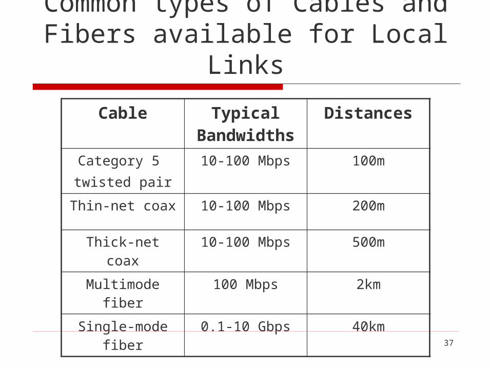
Common types of Cables and Fibers available for Local Links
Cable Typical Bandwidths
Distances
Category 5 twisted pair
10-100 Mbps 100m
Thin-net coax 10-100 Mbps 200m
Thick-net coax 10-100 Mbps 500m
Multimode fiber 100 Mbps 2km
Single-mode fiber 0.1-10 Gbps 40km

38
Category 5 (Cat-5) twisted pair --- it uses a thicker gauge than the twisted pair you find in your home --- is quickly becoming the within-building norm
Because of the difficulty and cost in pulling new cable through a building, every effort is made to make new technologies use existing cable Gigabit Ethernet , for example, has been designed to run
over Cat-5 wiring Fiber is typically used to connect buildings at a site

39
Leased Lines DS (Digital Signals)
DS1 and DS3 (also known as T1 and T3, respectively) are relatively old technologies that were originally defined for copper-based transmission media
DS1 is a widely used standard in telecommunications in North America and Japan to transmit voice and data between devices
DS1 is equal to the aggregation of 24 digital voice circuits of 64 Kbps each, and DS3 is equal to 28 DS1 links (= 28 × 1.544 Mbps)

40
Synchronous Transport Signal (STS) a standard for data transmissions over SONET
(Synchronous Optical Networking) STS-1 is the base link speed STS-N has N times the bandwidth of STS-1 STS-N links are for optical fiber STS-N links are sometimes called OC-N (optical
carrier) links

41
Common bandwidths available from the carriers
Service Bandwidth
DS1 (T1) 1.544 Mbps
DS3 (T3) 44.736 Mbps
STS-1 51.840 Mbps
STS-3 155.250 Mbps
STS-12 622.080 Mbps
STS-24 1.244160 Mbps
STS-48 2.488320 Mbps

Difference between STS and OC STS refers to the electrical transmission on the
devices connected to the link OC refers to the actual optical signal that is
propagated over the fiber Synchronous optical networking
a method for communicating digital information using lasers or light-emitting diodes (LEDs) over optical fiber
42

43
Service Bandwidth
POTS(Plain Old Telephone Service)
28.8-56 Kbps
ISDN 64-128 Kbps
xDSL 128 Kbps-100 Mbps
CATV (Cable TV) 1-40Mbps
Common Services to Connect Home (Last-Mile Links)
44
Plain Old Telephone Service (POTS)
The first option is a conventional modern over POTS
POTS is a term which describes the voice-grade telephone service
The technology is already at its bandwidth limit

Shannon’s Theorem Many works have done in the related areas of signal
processing and information theory How signals degrade over distance? How much data a given signal can effectively carry? The most notable work in this area is Shannon’s theorem
gives an upper bound to the capacity of a link, in terms of bits per second (bps), as a function of the signal-to-noise ratio of the link, measured in decibels (dB)
can be used to determine the data rate at which a modem can be expected to transmit binary data over a voice-grade phone line without suffering from too high an error rate
45
C = B × log2(1 + S/N)

Example assume that a voice-grade phone connection supports a frequency
range of 300 to 3,300 Hz Shannon’s theorem is typically given by the following formula:
C = B × log2(1 + S/N)
where C is the achievable channel capacity measured in hertz B is the bandwidth of the line (3,300 Hz - 300 Hz = 3,000 Hz) S is the average signal power N is the average noise power
46

the signal-to-noise ratio (S/N) is usually expressed in decibels, related as follows:
dB = 10 × log10(S/N)
assuming a typical decibel ratio of 30 dB, this means that S/N = 1,000
thus, we have
C = 3,000 × log2(l001)
which equals approximately 30 Kbps, roughly the limit of a 28.8 Kbps modem
47
C = B × log2(1 + S/N)

Given this fundamental limit, why is it possible for a 56 Kbps modems? reason-1
such rates depend on improved line quality, i.e., a higher signal-to-noise ratio than 30 dB
reason-2 the phone system is changed to have largely
eliminated analog lines that are bandwidth limited to 3,300 Hz
48

49
Integrated Services Digital Network (ISDN)
An ISDN connection includes two 64 Kbps channels one can be used to transmit data another can be used for digitized voice
a device that encodes analog voice into a digital ISDN link is called a CODEC (coder / decoder)
When the voice channel is not in use, it can be combined with the data channel to support up to 128 Kbps of data bandwidth

50
Digital Subscriber Loop or Digital Subscriber Line (DSL or xDSL)
A family of technologies that provide digital data transmission over the wires of a local telephone network High Data Rate Digital Subscriber Line (HDSL) Symmetric Digital Subscriber Line (SDSL) Asymmetric Digital Subscriber Line (ADSL) ISDN Digital Subscriber Line (IDSL) Rate-Adaptive Digital Subscriber Line (RADSL) Very High Speed Digital Subscriber Line (VDSL) Very High Speed Digital Subscriber Line 2 (VDSL2) Symmetric High-speed Digital Subscriber Line (G.SHDSL) Powerline Digital Subscriber Line (PDSL) Uni-DSL (UDSL)

51
ADSL 由於受到傳輸高頻訊號的限制, ADSL需要電信服務提供商端接入設備 (電話局 )和用戶終端 (用戶電話線 )之間的距離不能超過 5km
ADSL設備在傳輸中需要遵循以下標準之一 ITU-T G.992.1 (G.dmt)
G.dmt:全速率,下行 (downstream)8Mbps,上行(upstream)896Kbps
ITU-T G.992.2 (G.lite) G.lite:下行 1.5Mbps,上行 512Kbps
ITU-T G.994.1(G.hs) 可變位元率( VBR)
ANSI T1.413 Issue #2 下行 8Mbps,上行 896Kbps

更快更新的標準 ITU G.992.3/4
ADSL2 下行 12Mbps,上行 1.0Mbps ITU G.992.3/4
Annex J ADSL2 下行 12Mbps,上行 3.5Mbps ITU G.992.5
ADSL2+ 下行 24Mbps,上行 1.0Mbps ITU G.992.5
Annex M ADSL2+ 下行 24Mbps,上行 3.5Mbps 當電信服務提供商的設備端和用戶終端之間距離小於 1.3km時,還可使用速率更高的 VDSL(下行 55.2Mbps,上行19.2Mbps)
52

53
ADSL Wiring
Standard twisted pairConnecting residence
ADSLmodem
CO’s ADSLmodem
Digital connectionTo local network To analog
phoneTo telephoneswitch
Digital connectionTo provider
Telephone central office
Local loopCentraloffice
Subscriberpremises

The line from the subscriber to the central office is called local loop
54
Local loop
Central
office
Subscriber
premises
ADSL Connects the Subscriber to the Central Office via the Local Loop

55
VDSL
Very high data rate digital subscriber line Symmetric
Ranging from 12.96 to 55.2 Mbps
Runs over much shorter distances (1,000 to 4,500 feet) Which means it will not typically reach from the
home to the central office

56
VDSL
The telephone company would have to put VDSL transmission hardware in neighborhoods Fiber to the neighborhood
put VDSL transmission hardware in neighborhoods, with some other technology (e.g., STS-N running over fiber) connecting the neighborhood to the central office

57
STS-N
over fiber
VDSL at 12.96─ 55.2 Mbps
over 1000─ 4500 feet of copper
Central
office
Subscriber
premises
Neighborhood optical
network unit

58
Cable TV (CATV)
Cable moderns are an alternative to the various types of DSL
This technology uses the CATV infrastructure Some subset of the available CATV channels are
made available for transmitting digital data

59
Like ADSL, CATV is used in an asymmetric way Downstream: 40 Mbps / channel Upstream: 20 Mbps / channel Unlike DSL, the bandwidth is shared among all
subscribers in a neighborhood

Wireless Links
Wireless links transmit electromagnetic signals - radio, microwave, infrared, or even visible light - through space, even through vacuum
The availability to exchange signals without physical connectivity is what makes mobile communication devices possible
The further ability to broadcast that signal, and the fact that the hardware and power burden is primarily on the transmitting end, makes wireless communication well-suited to television and radio broadcasting
60

Wireless Links
Because wireless links all share the same wire, the challenge is to share it efficiently, without unduly interfering with each other
Most of this sharing is accomplished by dividing the “wire” along the dimensions of frequency or space Exclusive use of a particular frequency in a particular geographic
area may be allocated to an individual entity such as a corporation
61

Wireless Links
It is feasible to limit the area covered by an electromagnetic signal because such signals weaken, or attenuate, with the distance from their origin
To reduce the area covered by your signal, reduce the power of your transmitter
62

Frequencies allocations are determined by government agencies such as the Federal Communication Commission (FCC) in the United States
Specific bands (frequency ranges) are allocated to certain uses some bands are reserved for government use other bands are reserved for uses such as AM radio, FM
radio, television, satellite communication, and cell phones specific frequencies within these bands are then licensed to
individual organizations for use within certain geographical areas
63

Several frequency bands set aside for "license-exempt" usage - bands in which a license is not needed devices that use license-exempt frequencies are still
subject to certain restrictions 1st restriction: a limit on transmission power
this limits the range of a signal, making it less likely to interfere with another signal
example, a cordless phone might have a range of about 100 feet
2nd restriction: requires use of spread spectrum techniques
64

Spread spectrum spread the signal over a wider frequency band than normal in such
a way as to minimize the impact of interference from other devices originally designed for military use, so these “other devices” were
often attempting to jam ( 蓋台 ) the signal
Spread spectrum techniques frequency hopping spread spectrum (FHSS) direct sequence spread spectrum (DSSS)
65

Frequency hopping transmit the signal over a random sequence of frequencies,
i.e., first transmit at one frequency; then a second, then a third, and so on
the sequence of frequencies is not truly random, but is instead computed algorithmically by a pseudorandom number generator
the receiver uses the same algorithm as the sender - and initializes it with the same seed - and hence is able to hop frequencies in sync with the transmitter to correctly receive the frame
66
Direct sequence add redundancy for greater tolerance of interference each bit of data is represented by multiple bits in the transmitted
signal if some of the transmitted bits are damaged by interference, there is
usually enough redundancy to recover the original bit for each bit the sender wants to transmit, it actually sends the
exclusive-OR of that bit and n random bits as with frequency hopping, the sequence of random bits is
generated by a pseudorandom number generator known to both the sender and the receiver
67

The transmitted values, known as an n-bit chipping code, spread the signal across a frequency band that is n times wider than the frame
68
Example 4-bit chipping sequence

窄頻與展頻之比較

窄頻
特色:高功率,使用頻道愈窄則功率需求愈高 因為頻道很窄,必須靠高功率來確定接收無誤,如
FM 電台發送功率可達兩千瓦 功率愈高,則與隔鄰頻道間的 guard band( 保護
頻帶 ) 須越大 為讓窄頻訊號被接收,它必須比雜訊 (noise
level) 之功率高很多 缺點:很容易被惡意蓋台 (jam) 或干擾
因為頻帶很窄,很容易被其他頻率相同之高功率窄頻訊號所掩蓋


展頻
用比窄頻寬許多的頻道作通訊 例如在 1MHz 窄頻需要 10W 傳送,但若用
20MHz 展頻則只需要 10mW 傳送 較寬的頻道不容易被 jam 或被破壞
窄頻 jamming 只能對展頻的一小部分傳送造成影響,而大部份的資訊都能正確傳輸

展頻的頻道很寬,功率很低 此特色讓一般的接收器認為這只是雜訊,故在
早期展頻訊號的安全性比較高 此安全性讓軍方在 1950 到 1960 年代冷戰時期
採用展頻通訊,因為類似雜訊,展頻可用於戰區而不被敵方傳統接收設備察覺,安全性得以確保

展頻信號的調變方法 利用展頻碼或展頻序列 展頻碼是由虛擬雜訊或擬亂數產生器所產生
展頻調變的作用 增加傳送信號的頻寬
解調方式 接收端使用相同的數位序列解調此展頻信號 通道解碼器將解調信號還原成原始資料

直接序列展頻通訊 (DSSS) DSSS = Direct Sequence Spread
Spectrum 將使用者訊號加以處理
將原來 1 個位元的訊號,利用 10 個以上的位元空間來表示,使得原來高功率、窄頻率的訊號,變成低功率、寬頻率
原先一個位元,展頻後用多少個位元來代表,此數目稱為 Spreading Ration (SR) SR 值越高,愈能抵抗雜訊干擾 SR 值越低,愈可增加使用人數 ( 每人所用頻率較少 )

接收端將傳送訊號還原成原使用者的資料訊號 對非特定的接受器
spread spectrum 所產生的跳動訊號對它而言,只是脈衝雜訊,對整體而言是種較具安全性的通訊技術


DSSS operation flow 原傳送的 data signal
經 DSSS展頻後,即使受到干擾(interference),在接收後可用 pseudo code做 de-spread將整個能量集中,得到原來的 data signal
干擾部份 因為不是用 pseudo code產生,在 de-spread後,仍會散布於整個頻道

跳頻展頻通訊 (FHSS) FHSS = Frequency Hopping Spread Spectrum
每位使用者傳送資料的載波頻率作近似不規則的切換 將頻道劃分為若干個小頻道: f1, f2, f3, f4, ..., fk 傳輸訊號在這些小頻道之間跳躍發送 跳躍順序由『虛擬雜訊序列』 (PNS) 所產生

Frequency
f5
f4
f3
f2
f1
Frame Slot
Time

在同步且同時的情況下,接收兩端以特定型式的窄頻載波 (narrowband) 傳送訊號 FHSS 所產生的跳動訊號對非特定的接受器只是脈衝
雜訊 跳頻訊號須遵守 FCC (Federal
Communications Commission) 的規範,在台灣 必須使用 75 個以上的跳躍頻道 發射功率不可大於 1W ,若加上天線亦不可超過
4W

狹窄頻道間以跳躍模式傳遞訊號 信號透過一系列頻率範圍廣播出去 傳送前,傳送裝置會先偵測頻道 (channel)
若該頻道處於閒置狀態,信號會利用此頻道傳送出去
若該頻道已在使用,傳送端會跳躍 (hops) 到另一個頻道

相隔兩個跳躍頻道所需間隔時間 (dwell time) 的最大值為 400ms ,即每秒至少跳躍2.5次
接收端必須知道傳送端的跳躍程序,且傳送端與接收端必須同步切換頻道才可正常收送資料

License & License-Exempt Frequencies It is these license-exempt frequencies, with their spread
spectrum techniques and limited range, that are used by 802.11 (Wi-Fi), 802.15.1 (Bluetooth), and some flavors of 802.16 (WiMAX)
Different parts of the electromagnetic spectrum have different properties, making some better suited to communication and some less so E.g., some can penetrate buildings and some cannot
84

License & License-Exempt Frequencies
Governments regulate only the prime communication portion: the radio and microwave ranges
85

Among the unregulated spectra are the infrared and visual light ranges, which cannot penetrate walls Infrared is widely used in remote controls for television
and the like increasingly, it is also used in a variety of short-range
data exchange applications, based on standards established by the Infrared Data Association (IrDA)
86

For example, IrDA has defined a standard for "Point & Pay,¨ using infrared to conduct a financial transaction between a handheld device, such
as a mobile phone or PDA a stationary financial terminal such as a cash register
87

Visual light or infrared can also be focused by a laser to provide a high-bandwidth link between two stationary points - even though no mobility is involved - in situations where a wired link is less practical for some reason example, two buildings belonging to the same
organization but separated by a busy highway could communicate with lasers
88

89
2.2 Encoding
Link a physical medium carrying signals (including 1s
and 0s) in the form of electromagnetic waves binary data is encoded in the signal
Network adaptor contain a signaling component that encode bits into
signals at the sending node and decode signals into bits at the receiving node

90
Signals travel between signaling components
Bits flow between adaptors

91

92
Encoding the process of transforming information from one
format into another
Electronic encoding transforms a signal into a form optimized for
transmission or storage, generally done with a codec

93
Encoder a device used to change a signal (such as a
bitstream) or data into a code the code may serve any of a number of purposes
such as compressing information for transmission or storage, encrypting or adding redundancies to the input code, or translating from one code to another
Our problem is to encode bits onto signals

94
Encoding Schemes
Non-Return to Zero (NRZ) The obvious one of mapping data to digitals encode binary data onto electromagnetic signals e.g., 0 as low signal and 1 as high signal

95
The problem with NRZ is that a sequence of several consecutive 1s means that the signal stays high on the link for an extended period of time
Similarly, several consecutive 0s means that the signal stays low for a long time

96
There are two fundamental problems caused by long strings of 1s or 0s Baseline wander:
the receiver keeps an average of the signal it has seen so far, and then uses this average to distinguish between low and high signals The receiver concludes that it has just seen a 0 whenever
the signal is significantly lower than this average, vice versa
Too many consecutive 1s or 0s cause this average to change, making it difficult to detect a significant change

97
The second problem is that frequent transitions from high to low and vice versa are necessary to enable clock recovery
The clock recovery problem is that both the encoding and the decoding processes are driven by a clock—every clock cycle the sender transmits a bit and the receiver recovers a bit
The clocks have to be precisely synchronized Whenever the signal changes, then the receiver
knows it is at a clock cycle boundary, it can resynchronize itself

One approach that address this problem is called NRZI
Non-Return to Zero Inverted (NRZI) make a transition from current signal to encode a
one stay at current signal to encode a zero solves the problem of consecutive 1s but obviously does nothing for consecutive
0s
98

An alternative, called Manchester encoding Manchester
transmit XOR of the NRZ encoded data and the clock
think of the local clock as an internal signal that alternates from low to high; a low/high pair is one clock cycle
99

Manchester 0 being encoded as a low-to-high transition and 1
being encoded as a high-to-low transition because both 0s and 1s result in a transition to the
signal, the clock can be effectively recovered at the receiver
100

101
Encodings

102
Problem of Manchester encoding it doubles the rate at which signal transitions are
made on the link which means that the receiver has half the time to
detect each pulse of the signal the rate at which the signal changes is called the
link’s baud rate in the case of the Manchester encoding, the bit rate
is half the baud rate, so the encoding is considered only 50% efficient

103
if the receiver had been able to keep up with the faster baud rate required by the Manchester encoding in Figure 2.10, then both NRZ and NRZI could have been able to transmit twice as many bits in the same time period

104
Bit Rates and Baud Rates
bit rate and baud rate are not the same thing the Manchester encoding is an example of a
case in which a link’s baud rate is greater than its bit rate
a bit rate greater than the baud rate is also possible this imply that more than one bit is encoded on each
pulse sent over the link

105
ex. suppose you could transmit four distinguished
signals over a link rather than just two on an analog link, for example, these four signals
might corresponding to four different frequencies given four different signals, it is possible to encode
two bits of information on each signal the first signal means 00, the second signal means 01, .. a sender transmit 1000 pulse per second would be able
to send 2.000 bits

106
a final encoding we consider is called 4B/5B attempts to address the inefficiency of the Manchester
encoding without suffering from the problem of having extended durations of high or low signals
4B/5B idea
insert extra bits into the bitstream so as to break up long sequences of 0s or 1s
every 4 bits of data encoded in a 5-bit code that is then transmitted to the receiver, hence the name 4B/5B

5-bit codes selected in the following way no more than one leading 0 no more than two trailing 0s
when sent back-to-back, no pair of 5-bit codes results in more than three consecutive 0s being transmitted
107

108
the resulting 5-bit codes are transmitted using NRZI which explains why the code is only concerned about
consecutive 0s NRZI already solves the problems of consecutive 1s
the 4B/5B encoding results in 80% efficiency

Example of 4B/5B Encoding

The table gives the 5-bit codes that correspond to each of the 16 possible 4-bit data symbols 5 bits are enough to encode 32 different codes, and we are using
only 16 of these for data 16 codes (=1+1+1+7+6) left for other purposes
code 11111 : used when the line is idle code 00000 : used when the line is dead code 00100 : interpreted to mean halt 7 codes are not valid because they violate the "one leading 0,
two trailing 0s," rule 6 codes represent various control symbols, e.g. used in framing
protocols of FDDI
110

111
2.3 Framing
Break sequence of bits into a frame We are focusing on packet-switched networks Blocks of data (frames) are exchanged between
nodes
It is the network adaptor that enables the nodes to exchange frames When node A wishes to transmit a frame to node
B, it tells its adaptor to transmit a frame from the node’s memory

112
This results in a sequence of bits being sent over the link
The adaptor on node B then collects together the sequence of bits arriving on the link and deposits the corresponding frame in B’s memory
Determine where the frame begins and ends is the central challenge faced by the adaptor

113
Bits flow between adaptors and frames flow between hosts

114
Approaches
Byte-Oriented Protocols one of the oldest approaches to framing root in connecting terminals to mainframes view each frame as a collection of bytes
(characters) rather than a collection of bits

examples sentinel-based approaches
Binary Synchronous Communication (BISYNC)
Point-to-Point Protocol (PPP) byte-counting approach
Digital Data Communications Message Protocol (DDCMP)
115

116
Bit-Oriented Protocols views the frame as a collection of bits these bits might come from
some character set, such as ASCII pixel values in an image instructions and operands from an executable file
example High-Level Data Link Control (HDLC)

Clock-Based Framing Synchronous Optical Network (SONET)
117

118
Byte Bit Clock
SONETHDLC
DDCMPPPPBISYNC
Sentinel Count

119
Byte-Oriented Protocol : BISYNC
Binary Synchronous Communication (BISYNC) Developed by IBM in the late 1960s Use sentinel characters to indicate start/end Format
SYN (synchronization) : beginning Data portion: between STX (start of text) and ETX (end
of text) SOH (start of header) : serves much the same purpose
as the STX field

Problem the ETX character might appear in the data portion of the
frame BISYNC overcomes this problem by “escaping” the ETX
character by preceding it with a data-link-escape (DLE) character
this approach is often called character stuffing because extra characters are inserted in the data portion of the frame
CRC (Cyclic Redundancy Check): detect transmission errors
120

121
Byte-Oriented Protocol : PPP Point-to-Point Protocol (PPP) Commonly used to carry Internet Protocol packets over
various sorts of point-to-point links Also uses sentinels and character stuffing Format
Flag (start-of-text): 01111110 Address: default value Control: default value

Protocol: used for demultiplexing, it identifies the high-level protocol such as IP or IPX (Novell)
Payload: size can be negotiated (default is 1,500 bytes)
Checksum: either 2 (by default) or 4 bytes long
122

Several of the field sizes of the PPP frame format are negotiated rather than fixed this negotiation is conducted by a protocol called
Link Control Protocol (LCP) PPP and LCP work in tandem LCP sends control messages encapsulated in PPP
frames and then turns around and changes PPP’s frame format based on the information contained in those control messages
123

124
Byte-Oriented Protocol : DDCMP
Digital Data Communication Message Protocol (DDCMP)
Used in Digital Equipment Corporation’s DECNET
Count: specifies how many bytes are contained in the frame’s body

One danger with this approach a transmission error could corrupt the count field, in
which case the end of the frame would not be correctly detected
should this happen, the receiver will accumulate as many bytes as the bad COUNT field indicates and then use the error detection field to determine that the frame is bad (framing error)
the receiver will then wait until it sees the next SYN character to start collecting the bytes that make up the next frame
125

126
Bit-Oriented Protocol : HDLC
Synchronous Data Link Control (SDLC) protocol developed by IBM is an example of a bit-oriented protocol
SDLC was later standardized by the ISO as the High-Level Data Link Control (HDLC) protocol
Beginning and end of a frame: 01111110

Because this sequence (01111110) might appear anywhere in the body of the frame in fact, the bits 01111110 might cross byte boundaries bit-oriented protocols use the analog of the DLE (data-
link-escape) character, a technique known as bit stuffing
Operation flow of bit stuffing on the sending side
any time five consecutive 1s have been transmitted from the body of the message (i.e., excluding when the sender is trying to transmit the distinguished 01111110 sequence), the sender inserts a 0 before transmitting the next bit
127

on the receiving side should five consecutive 1s arrive, the receiver makes
its decision based on the next bit it sees if the next bit is a 0, it must have been stuffed,
and so the receiver removes it if the next bit is a 1, then one of two things is true
either this is the end-of-frame marker or an error has been introduced into the bitstream
128

by looking at the next bit if it sees a 0 (i.e., 01111110), then it is the
end-of-frame marker if it sees a 1 (i.e., 01111111), then there
must have been an error and the whole frame is discarded, in this case, the receiver has to wait for the next 01111110 before it can start receiving again
129

130
Clock-Based Framing : SONET
Synchronous Optical Network (SONET) first proposed by Bell Communications Research (Bellcore) then developed under the American National Standards Institute
(ANSI) for digital transmission over optical fiber, it has since been adopted by the ITU-T
The dominant standard for long-distance transmission of data over optical networks

STS-1 frame runs at 51.84 Mbps arranged as 9 rows of 90 bytes each the first 3 bytes of each row are overhead the rest is available for data the first 2 bytes of the frame contain a special bit pattern
used for enabling the receiver to determine where the frame starts
131

Frame overhead bits that are added at regular intervals to a digital signal
at the sending end of a digital link and used to provide network functions such as framing, operations, administration, and maintenance
the overhead bytes of a SONET frame are encoded using NRZ
132

133
STS-1 Frame

134
SONET supports multiplexing of multiple low-speed links
A given SONET link runs at one of a finite set of possible rates, ranging from 51.48 Mbps (STS-1) to 2,448.32 (STS-48), and beyond
A single SONET frame can contain subframes for multiple lower-rate channels
Clock-based each frame is 125μs long

135
A SONET frame STS-N frame can be thought of as consisting of N STS-
1 frames 810 bytes long at STS-1 rate 2,430 bytes long at STS-3 rate
The bytes from these frames are interleaved a byte from the first frame is transmitted, then a byte
from the second frame is transmitted, and so on ensure that the bytes in each STS-1 frame are evenly
paced

STS-Nc link (concatenate) the payload from these N STS-1
frames to form a larger STS-N payload
136
Three STS-1 frames multiplexed onto one STS-3c frame

137
2.4 Error Detection
Two basic approaches that can be taken when the recipient of a message detects an error one is to notify the sender that the message was
corrupted so that the sender can retransmit a copy of the message
alternatively, there are some types of error detection algorithms that allow the recipient to reconstruct the correct message even after it has been corrupted; such algorithms rely on error correcting codes

138
Error detection techniques two-dimensional parity check
used by the BISYNC protocol when it is transmitting ASCII characters (CRC is used as the error code when BISYNC is used to transmit EBCDIC)
Cyclic Redundancy Check (CRC) used in nearly all the link-level protocols example : HDLC, DDCMP, CSMA and token ring
protocols
checksum used by several Internet protocols
BISYNC

139
Error Types

140
Error Detection


142
Parity Check

143

144


146
Cyclic Redundancy Check
The theoretical foundation of the cyclic redundancy check is rooted in a branch of mathematics called finite fields
In general, we can provide quite strong error detection capability while sending n redundant bits for an m-bit message, where n << m on an Ethernet, a frame carrying up to 12,000 bits
(1,500 bytes) of data requires only a 32-bit CRC code CRC-32 (n = 32)
such a code will catch the overwhelming majority of errors

147
Add n bits of redundant data to an m-bit message let n << m e.g., n = 32 bits and m = 12,000 bits (1500 bytes)
An (n+1)-bit message as being represented by an n degree polynomial, i.e., a polynomial whose highest order term is xn e.g., in case of n = 7 and MSG=10011010 then
M(x) = x7+x4+x3+x1
Think of a sender and a receiver as exchanging polynomials with each other

148
A sender and receiver have to agree on a divisor polynomial C(x) let n be the degree of some divisor polynomial, e.g.,
C(x) = x3 + x2 + 1, n=3 Module 2 polynomial arithmetic, e.g.
the polynomial x3+1 is divided by x3+x2+1 with the remainder [bitwise exclusive-OR the coefficients of each term]0 ╳ x3+1 ╳ x2+0 ╳ x1+0 ╳ x0 = x2
1001 is divided by 1101 with the remainder 0100

149

150

151

152
Commonly Used and Standardized CRCs

153

154

155
Types of errors can be detected by a C(x) of degree n all single-bit errors, as long as the xn and x0 terms have
nonzero coefficients all double-bit errors, as long as C(x) has a factor with at
least three terms any odd number of errors, as long as C(x) contains the
factor (x +1) any “burst” error (i.e., sequence of consecutive errored
bits) for which the length of the burst is less than n bits (most burst error of larger than n bits can also detected)

156
Checksum

157

158
Internet Checksum Algorithm
Idea sender
adds up all the words that are transmitted transmit the result (checksum) of that sum
receiver performs the same calculation on the received data compares the result with the received checksum
if any transmitted data, including the checksum itself, is corrupted, then the results will not match, so the receiver knows that an error occurred

159
Checksum for Internet protocols consider the data being checksummed as a
sequence of 16-bit integers add them together using 16-bit ones
complement arithmetic take the ones complement of the result that 16-bit number is the checksum

160
Ones complement arithmetic a negative integer -x is represented as the
complement of x, i.e., each bit of x is inverted when adding numbers in ones complement
arithmetic, a carryout from the most significant bit needs to be added to the result

161
example, the addition of -5 and -3 in ones complement arithmetic on 4-bit integers +5 is 0101, so -5 is 1010 +3 is 0011, so -3 is 1100 add 1010 and 1100, we get 0110 add carryout to 0110, we get 0111, which is
the ones complement representation of -8

162
Internet Checksum Algorithmu_shortcksum(u_short *buf, int count){ register u_long sum = 0; while (count--) { sum += *buf++; if (sum & 0xFFFF0000) { /* carry occurred, so wrap around */ sum &= 0xFFFF; sum++; } } return ~(sum & 0xFFFF);}

163
count gives the length of buf measured in 16-bit units
the routine assumes that buf has already been padded with 0s to a 16-bit boundary
the if statement inside the while loop if there is a carry into the top 16 bits of sum, then we
increment sum