(,1 2 1/,1( - united states environmental protection agency acid plants are used primarily to...
TRANSCRIPT

Citation: 36 Fed. Reg. 24876 1971
Content downloaded/printed from HeinOnline (http://heinonline.org)Thu Jul 2 09:31:39 2015
-- Your use of this HeinOnline PDF indicates your acceptance of HeinOnline's Terms and Conditions of the license agreement available at http://heinonline.org/HOL/License
-- The search text of this PDF is generated from uncorrected OCR text.

RULES AND REGULATIONS
STitle 4-PIIYEIEI0 OF
Chapter I-Environmental ProtectionAgency
SUBCHAPTER C-AIR PROGRAMS
PART 60-STANDARDS OF PERFORM-ANCE FOR NEW STATIONARYSOURCESOn August 17. 1971 (36 F.R. 15704)
pursuant to section 111 of the Clean AirAct as amended, the Administratorproposed standards of performance forsteam generators, portland c e m e n tplants, incinerators, nitric acid plants,and sulfuric acid plants. The proposedstandards, applicable to sources the con-struction or modification of which wasInitiated after August 17, 1971, includedemission limits for one or more of fourpollutants (particulate matter, sulfur?dioxide, nitrogen oxides, and sulfuricacid mist) for each source category. Theproposal included requirements for per-formance testing, stack gas monitoring,record keeping and reporting, and pro-cedures by which EPA will provide pre-construction review and determine theapplicability of the standards to specificsources.
Interested parties were afforded anopportunity to participate in the rulemaking by submitting comments. A totalof more than 200 interested parties, in-cluding Federal, State, and local agen-cies, citizens groups, and commercial andindustrial organizations submitted com-ments. Following a review of the pro-posed regulations and consideration ofthe comments, the regulations, includ-ing the appendix, have been revised andare being promulgated today. The prin-cipal revisions are described below:
1. Particulate matter performancetesting procedures have been revised toeliminate the requirement for impingersin the sampling train. Compliance will bebased only on material collected in thedry filter and the probe preceding thefilter. Emission limits have been adjustedas appropriate to reflect the change intest methods. The adjusted standards re-quire the same degree of particulate con-trol as the originally proposed standards.
2. Provisions have been added wherebyalternative test methods can be used todetermine compliance. Any person whoproposes the use of an alternativemethod will be obliged to provide evi-dence that the alternative method isequivalent to the reference method.
3. The definition of modification, as itpertains to increases in production rateand changes of fuels, has been clarified.Increases in production rates up to designcapacity will not be considered a modifi-cation nor will fuel switches if the equip-ment was/originally designed to accom-modate such fuels. These provisions willeliminate inequities where equipment hadbeen put into partial operation prior tothe proposal of the standards.
4. The definition of a new source was,clarifled to include construction which
is completed within an organization aswell as the more common situationswhere the facility is designed and con-structed by a contractor.
5. The provisions regarding requestsfor EPA plan xeview and determinationof construction or modification have beenmodified to emphasize that the submittalof such requests and attendant informa-tion is purely voluntary. Submittal ofsuch a request will not bind the operatorto supply further information; however,lack of sufficient information may pre-vent the Administrator from renderingan opinion. Further provisions have beenadded to the effect that information sub-mitted voluntarily for such plan reviewor determination of applicability will beconsidered confidential, if the owner oroperator requests such confidentiality.
6. Requirements for notifying the Ad-ministrator prior to commencing con-struction have been deleted. As proposed,the provision would have required notifi-cation prior to the signing of a contractfor construction of a new source. Ownersand operators still will be required tonotify the Administrator 30 days prior toinitial operation and to confirm theaction within 15 days after startup.
7. Revisions were incoporated to per-mit compliance testing to be deferred upto 60 days after achieving the maximumproduction rate but no longer than 180days after initial startup. The proposedregulation could have required testingwithin 60 days after startup but definedstartup as the beginning, of routineoperation. Owners or operators will berequired to notify the Administrator atleast 10 days prior to compliance testingso that an EPA observer can be on hand.Procedures have been modified so thatthe equipment will have to be operatedat maximum expected production rate,rather than rated capacity, during com-pliance tests.
8. The criteria for evaluating perform-ance testing results have been simplifiedto eliminate the requirement that allvalues be within 35 percent of the aver-age. Compliance will be based on theaverage of three repetitions conducied inthe specified manner.
9. Provisions were added to requireowners or operators of affected facilitiesto maintain records of compliance tests,monitoring equipment, pertinent anal-yses, feed rates, production rates, etc. for2 years and to make such informationavailable on request to the Administra-tor. Owners or operators will be requiredto summarize the recorded data dailyand to convert recorded data into theapplicable units of the standard.
10. Modifications were made to thevisible emission standards for steamgenerators, cement plants, nitric acidplants, and sulfuric acid plants. TheRingelmann standards have been de-leted; all limits will be based on opacity.In every case, the equivalent opacity willbe at least as stringent as the proposedRingelmann number. In addition, re-quiremehts have been altered for threeof the source cate-gories so that allowableemissions will be less than 10 percentopacity rather than 5 percent or lessopacity. There were many comments
that observers could not accuratlyevaluate emissions of 5 percent opacity.In addition, drafting errors in the pr-oposed visible emision limits for cementkilns and steam generators were cor-rected. Steam generators will be limitedto visible emissions not greater than 20percent opacity and cement tftlns to n tgreater than 10 percent opacity.
11. Specifications for monitoring de-vices were clarified, and directives forcalibration were included. The lnotru-ments are to be calibrated at least oncea day, or more often If specified by themanufacturer. Additional guidance onthe selection and use of such Instrumentswill be provided at a later date.
12. The requirement for sulfur dioxidemonitoring at steam generators wasdeleted for those sources which willachieve the standard by burning low-sul-fur fuel, provided that fuel analysis iconducted and recorded daily. AmericanSociety for Testing and laterlahsampling techniqum are specified forcoal and fuel oil.
13. Provisions were added to the steamgenerator standards to cover those in-stances where mixed fuels are burned.Allowable emissions will be determinedby prorating the heat input of each fuel,however, in the case of sulfur dioxide, theprovisions allow operators the option ofburning low-sulfur fuels (probablynatural gas) as a means of compliance,
14. Steam generators fired with lignitehave been exempted from the nitrogenoxides limit. The revision was made inview of the lack of Information on sometypes of lignite burning. When more In-formation is developed, nitrogen oxidesstandards may be extended to lignitefired steam generators.
15. A provision was added to make Itexplicit that the sulfuric acid plantstandards will not apply to scavengeracid plants. As stated In the backgrounddocument, APTD 0711, which was Issucdat the time the proposed standards werepublished, the standards were not meantto apply to such operations, e.g., wheresulfuric acid plants are used primarilyto control sulfur dioxide or other sulfurcompounds which would otherwise bevented into the atmosphere.
16. The regulation has been revisedto provide that all materials submittedpursuant to these regulations will be di-rected to EPA's Office of General En-forcement.
17. Several other technical changeshave also been made. States and Inter-ested parties are urged to make a carefulreading of these resgulations.
As required by section 111 of the Act,the standards of parformance promul-gated herein "reflect the degree of emils-sion reduction which (taking Into ac-count the cost of achieving such reduc-tion) the Administrator determlnes hasbeen adequately demonstrated". Thestandards of performance are based onstationary source testing conducted bythe Environmental Protection Agencyand/or contractors and on data derlvdfrom various other sources, including theavailable technical literature. In the com-ments on the proposed standards, manyquestions were raised as to cozts and
FEDERAL REGISTER, VOL 36, NO. 247-THURSDAY, DECE.BER 23, 1971
24376

RUILES AND REGULATIONS
demonstrated capablilty of control sys-tems to meet the standards. These com-ments have been evaluated and investi-gated, and it is the Administrator'sjudgment that emission control systemscapable of meeting the standards havebeen adequately demonstrated and thatthe standards promulgated herein areachievable at reasonable costs.
The regulations establishing standardsof performance for steam generators, in-cinerators, cement plants, nitric acidplants, and sulfuric acid plants are here-by promulgated effective on publicationand apply to sources, the construction ormodification of which was commencedafter August 17, 1971.
Dated: December 16, 1971.WLLam D. RucKE msAus,
Administrator,Environmental Protection Agency.
A new Part 60 is added to Chapter I,Title 40, Code of Federal Regulations, asfollows:
Subpart A-General Provisions
Sec.60.1 Applicability.60.2 Definitions.60.3 Abbreviations.60.4 Address.60.5 Determination of construction or
modiftcation.60.6 Review of plans.60.7 lotiflcation and recordkeeping.60.8 Performance tests.60 9 Avalafbility of information.60.10 State authority.
Subpart D-Standards of Performance forFossil Fuel-Fired Steam Generators
60.40 Applicab1Uty and designation of af-fected facility.
60.41 Definitions.60.O2 Standard for particulate matter.60.43 Standard for sulfur dioxide.60.44 Standard for nitrogen oxides.60.45 Emission and fuel monitoring.60.46 Test methods and procedures.
Subpart E-Standards of Performance forInclinerators
60.50 Applicablity and designation of af-fected facility.
60.51 Definitions.60.52 Standard for particulate matter.60.53 Monitoring of operations.60.54 Test methods and procedures.
Subpart F-Standards of Performance forPortland Cement Plants
60.60 Applicability and designation ofaffected facility.
60.61 Definitions.60.62 Standard for particulate matter.60.63 Monitoring of operations.60.61 Test methods and procedures.
Subpart G-Standards of Performance for NitricAcid Plants
60.70 ApplicabIlity and designation of af-fected facility.
60.71 Definitions.60.72 Standard for nitrogen oxides.60.73 Emission monitoring.60.74 Test methods and procedures.
Subpart H-Standards of Performance for SulfuricAcid Plants
60.80 AppUcability and designation of af-fected facility.
60.81 Definitions.
60.82 Standard for sulfur dioxide.60.83 Standard for acid mist60.84 Ermimon monitoring.60.85 Test methods and procedures,
APpam=-Tfssr MrTors
Method 1-Sample and velocity traverses forstationary sources.
Method 2-Dctcrmlnatlon of stack gas veloc-ity and volumetric flow rate (Typo Spitot tube).
Method 3-Gas analysis for carbon dioxide,excess air, and dry molecular weight.
Method 4-Determination of moisture Instack gases.
Method 5-DeterminatIon of particulatoemissions from stationary courccs.
Method 6-Determinatlon of sulfur dioxideemissions from stationary sources.
M Method 7-Determination of nitroen oxidoemissions from stationary rources.
Method 8-Dtermlnatlon of sulfuric acidmist and sulfur dioxide emissionsfrom stationary sources.
Method 9--Visual determination of the opac-lty of emissions from stationarysources.
Auroarry: The provisions of this Part 6OIssued under sections 111, 114, Cle= Air Act;Public Law 91-604, 84 Stat. 1713.
Subpart A-General Provisions
§ 60.1 Applicability.The provisions of this part apply to
the owner or operator of any stationarysource, which contains an affected facil-ity the construction or modification ofwhich is commenced after the date ofpublication in this part of any proposedstandard applicable to such facility.§ 60.2 Definitions.
As used in this part, all terms notdefined herein shall have the meaninggiven them in the Act:
(a) "Act" means the Clean Air Act(42 U.S.C. 1857 et seq., as amended byPublic Law 91-604, 84 Stat. 1676).
(b) "Administrator" means the Ad-ministrator of the Environmental Pro-tection Agency or his authorized repre-sentative.(c) "Standard" means a standard of
performance proposed or promulgatedunder this part
d) "Stationary source" means anybuilding, structure. facility, or installa-tion which emits or may emit any airpollutant.(e) "Affected facility" means, with
reference to a stationary source, any ap-paratus to which a standard Is applicable.
(f) "Owner or operator" means anyperson who owns, leases, operates, con-trols, or supervises an affected facilityor a stationary source of which an af-fected facility is a part.
(g) "Construction" means fabrication,erection, or installation of an affectedfacility.
(h) 'Modification" means any physicalchange in, or change in the method ofoperation of, an affected facility whichincreases the amount of any air pol-lutant (to which a standard applies)emitted by such facility or which resultsin the emission of any air pollutant (towhich a standard applies) not previouslyemitted, except that:
(1) Routine maintennce, repair, andreplacement shall not be consideredphysical changes, and
(2) The following shall not bq consid-ered a change In the method ofop tion:
(i) An increase in the productionrate, if such increase does not exceed theoperating design capacity of the affectedfacility;
(i) An increae in hours of operation;(i1) Use of an alternative fuel or raw
material if. prior to the date any stand-ard under this part becomes applicableto such facility, as provided by § 60.1,the affected facility Is designed to ac-commodate such alternative.use.
(I) "Commenced" means that an own-er or operator has undertaken a con-tinuous pro-ram of construction ormodification or that an owner or opera-tor has entered into a binding agree-meat or contractual obligation to under-take and complete, within a reasonabletime. a continuous proxram of construc-tion or modification.
Wi) "Opacity" means the degree towhich enisions reduce the transmissionof licht and obscure the view of an objectIn the background.
(k) "Nitrozen oxides" means all ox-Ides of nitrogen except nitrous oxide, asmeasured by tes methods set forth inthis part.
(1) "Standard of normal conditions"means 7O Fahrenheit (21.1 ° centi-grade) and 29.92 In. Hg (760 mm. Hg).(m) "Proportional sampling" means
sampling at a rate that produces a con-stant ratio of sampling rate to stack gasflow rate.
(n) 'IsodInetle sampling" meanssampling In which the linear velocity ofthe gas entering the sampling nozzle isequal to that of the undisturbed gasstrearm at the sample point.
(W) "Startup" means the setting inoperation of an affected facility for anypurpose.
§ 60.3 Abbreviations,The abbreviations used In this part
have the following meanings in bothcapital and lower case:B.t.u.-Britt h thermal unitcal.--calorlo(s).c.f.m.-cubo feet per minute.CO--carbon dioxide.g.-gram(s).gr.-grain(s).mg-mflhlgram(o).mm.-milmCter(s).L-ter(o).nm,-nanometer(s), -10-' mete..g.-mcr0-ram(o), 10-4 gram.
Hg.-mercury.in.-nch(ea).- O00.
lb.-pound (a).ml-millUiiter(o).21o.-number.,-percent.1O-nitric oxide.10--nitrC-en dioxide.
110--nitrogen oxidcs=1T--normai cubic meter..f.-atandard cubic feet.
60,--oulfur dioxide.,EO,-ulfuric acid.
SO-ulfur trioxide.
FEDERAL REGISTER, VOL 36, NO. 247-THURSDAY, DECE1,1BER 23, 1971
24S77

24878
ft.--cubic feet.ft.m-square feet.
lm-r-inute(s).br.-hour(s).
§ 60.4 Address.
All applications, requests, submissons.and reports under this part shall be sub-mitted in triplicate and addressed to theEnvironmental Protection Agency, Officeof General Enforcement, Waterside MallSW., Washington, DC 20460.§ 60.5 Determination of construction or
modification.When requested to do so by an owner
or operator, the Administrator will makea determination of whether actions takenor intended to be taken by such owner oroperator constitute construction or modi-fication or the commencement thereofwithin the meaning of this part.
§ 60.6 Review of plans.
(a) When requested to do so by anowner or operator, the Administrator willreview plans for construction or m=difi-cation for the purpose of providingtechnical advice to the owner or operator.
(b) (1) A separate request shall besubmitted for each affected facility.
(2) Each request shall (i) identify thelocation of such affected facility, and (ii)be accompanied by technical informationdescribing the proposed nature, size,design, and method of operation of suchfacility, including Information on anyequipment to be used for measurement orcontrol of emissions.,
(c) Neither a request for plans reviewnor advice furnished by the Administra-tor in response to such request shall (1)relieve an owner or operator of legalresponsibility for compliance with anyprovision of this part or of any applicableState or local requirement, or (2) preventthe Administrator from implementing orenforcing any provision of this part ortaking any other action authorized by theAct.
§ 60.7 Notification and record keeping.
(a) Any owner or operator subject tothe provisions of this part shall furnishthe Administrator written notification asfollows:
(1) A notification of the anticipateddate of initial startup of an affectedfacility not more than 60 days or lessthan 30 days prior to such date.
(2) A notification of the actual dateof initial startup of an affected facilitywithin 15 days after such date.
(b) Any owner or operator subject tothe provisions of this part shall maintainfor a period of 2 years a record of theoccurrence and duration of any startup,shutdown, or malfunction in operation ofany affected facility.
§ 60.8 Performance tests.
(a) Within 60 days after achieving themaximum production rate at which theaffected facility will be operated; but notlater than 180 days after initial startupof such facility and at such other timesas may be required by the Administratorunder section 114 of the Act, the owner
RULES AND REGULATIONS
or operator of such facility shall conductperformance test(s) and furnish the Ad-ministrator a written report of the resultsof such performance test(s).
(b) Performance tests shall be con-ducted and results reported in accord-ance with the test method set forth inthis part or equivalent methods approvedby the Administrator; or where the Ad-ministrator determines that emissIonsfrom the affected facility are not sus-ceptible of being measured by suchmethods, the Administrator shall pre-scribe alternative test procedures fordetermining compliance with the re-quirements of this part.
(c) The owner or operator shall permitthe Administrator to conduct perform-ance tests at any reasonable time, shallcause the affected facility to be operatedfor purposes of such tests under suchconditions as the Administrator shallrpecify based on representative perform-ence of the affected facility, and shallmake available to the Administratorsuch records as may be necessary todetermine such performance.
(d) The owner or operator of anaffected facility shall provide the Ad-ministrator 10 days prior notice of theperformance test to afford the Admin-istrator the opportunity to have an ob-server present.
(e) The owner or operator of anaffected facility shall provide, or cause tobe provided, performance testing facil-ities as follows:
(1) Sampling ports adequate for testmethods applicable to such facility.
(2) Safe sampling platform(s).(3) Safe access to sampling plat-
form (s).(4) Utilities for sampling and testing
equipment.(f) Each performance test shall con-
sist of three repetitions of the applicabletest method. For the purpose of deter-mining compliance with an applicable-standard of performance, the average ofresults of all repetitions shall apply.
§ 60.9 Availability of information.
(a) Emission data provided to, orotherwise obtained by, the Administra-tor in accordance with the provisions 6fthis part shall be available to the public.
(b) Except as provided in paragraph(a) of this section, any records, reports,or information provided to, or otherwiseobtained by, the Administrator in accord-ance with the provisions of this partshall be available to the public, exceptthat (1) upon a showing satisfactory tothe Administrator by any person thatsuch records, reports, or information, orparticular part thereof (other thanemission data), if made public, woulddivulge methods or processes entitled toprotection as trade secrets of such per-son, the Administrator shall considersuch records, reports, or information, orparticular part thereof, confidential inaccordance with the purposes of section1905 of title 18 of the United StatesCode, except that such records, reports,or information, or particular part there-of, may be disclosed to other officers, em-ployees, or authorized representatives of
the United States concerned with caerry-ing out the pro-visons of the Act or vhfnrelevant in any proceeding under thoAct; and (2) Information received by thoAdministrator solely for the purpoz,,x (f§§ 60.5 and 60.6 shall not be dhclo:cdif it is identified by the omer or opert-tor as being a trade saret or cwii-mercial or flnancial Informat on whichsuch owner or operator conlIdei.Aconfidential.§ 60.10 State authority.
The provisions of this part rhPl notbe construed In any manner to precludeany State or political subdivlsion thereoffrom:
(a) Adopting and enforcing tny cmit:-slon standard or limitation applicable toan affected facility, provided that suchemission standard or limitation is notless stringent than the standard appli-cable to such facility.
(b) Requiring the owner or operatorof an affected facility to obtain permits,licenses, or approvals prior to initiatingconstruction, modification, or operationof such facility.
Subpart D-Standards of Porformancofor Fossil-Fuel Fired Steam Gonorators§ 60.40 Applicability and deozgation of
affected facility.The provisions of this subpart are ap-
plicable to each fossil fuel-fired steamgenerating unit of more than 250 mllionB.t.u. per hour heat input, which ls theaffected facility.§ 60.41 Definition-c
As used In this subpart, all terms notdefined herein shall have the meaninggiven them in the Act, and In SubpartA of this part.
(a) "Fossil fuel-fired steam generat-ing unit" means a furnace or boiler uscdIn the process of burning fossil -fuelfor the primary purpozs of producingsteam by heat transfer.
(b) 'Fossil fuel" means natural gas,petroleum, coal and any form of solid,liquid, or gaseous fuel derived fromsuch materials.
(c) "Particulate matter" means anyfinely divided liquid or solid material,other than uncombined water, as meas-ured by Method 5.§ 60.42 Standard for particulate matter,
On and after the date on which thoperformance test required to be con-ducted by § 60.8 is initiated no owneror operator subject to the provisions ofthis part shall discharge or caue thodischarge into the atmosphere of par-ticulate matter which Is:
(a) In excess of 0.10 lb. per millionB.t.u. heat input (0.18 g. per million cal.)maximum 2-hour averago.
(b) Greater than 20 percent opacity,except that 40 percent opacity shall bopermissible for not more than 2 mlnutelin any hour.(c) Where the presence of uneom-
bined water is the only reason for fail-ure to meet the requirements of para-graph (b) of this section such failureshall not be a violation of this section.
FEDERAL REGISTER, VOL 36, NO. 247-THURSDAY, DECEMBErl 23, 1971

§ 60.43 Standard for sulfur dioxide.On and after the date on which the
performance test required to be con-ducted by § 60.8 is initiated no owneror operator subject to the provisionsof this part shall discharge or cause thedischarge into the atmosphere of sulfurdioxide in -xcess of:
(a) 0.80 lb. per million B.t.u. heat in-put (1.4g. per million cal.), maximum 2-hour average, when liquid fossil fuel isburned.
(b) 1.2 lbs. per million B.t.u. heat input(2.2 g. per million cal.), maximum 2-hour average, when solid fossil fuel isburned.
(c) Where different fossil fuels areburned simultaneously in any combina-tion, the applicable standard shall bedetermined by proration. Complianceshall be determined using the followingformula:
y(0.0)+lz(l.2 )
where:x is the percent of total heat input derived
from gaseous fossil fuel and,y is the percent of total heat input derived
from liquid fossil fuel and,z is the percent of total heat Input derived
from solid fossil fuel.
§ 60.44 Standard for nitrogen oxides.On and after the date on which the
performance test required to be con-ducted by § 60.8 is initiated no owner oroperator subject to the provisions of thisparxt shall discharge or cause the dis-charge into the atmosphere of nitrogenoxides in excess of:
(a) 0.20 lb. per million B.t.u. heat in-put (0.36 g. per million cal), maximum2-hour average, expressed as NOz, whengaseous fossil fuel is burned.
(b) 0.30 lb. per million B.t.u. heat in-put (0.54 g. per million cal), maximum2-hour average, expressed as NO:, whenliquid fossil fuel is burned-
(c) 0.70 lb. per million B.t.u. heat in-put (1.26 g. per million cal.), maximum2-hour average, expressed as NO2 whensolid fossil fuel (except lignite) is burned.
(d) When different fossil fuels areburned simultaneously in any combina-tion the applicable standard shall be de-termined by proration. Compliance shallbe determined by using the followingformula:
x(O.20) +y(O.3o) +z(O.7o)
where:x is the percent of total heat input derived
from gaseous fossil fuel and,y is the percent of total heat input derived
from liquid fossil fuel and,z is the percent of total heat input derived
from solid fossil fueL
§ 60.45 Emission and fuel monitoring.(a) There shall be installed, cali-
brated, maintained, and operated, in anyfossil fuel-fired steam generating unitsubject to the provisions of this part,emission monitoring instruments asfollows:
(1) A photoelectric or other typesmoke detector and recorder, except
RULES AND REGULATIONS
where gaseous fuel Is the only fuelburned.
(2) An instrument for continuouslymonitoring and recording sulfur dioxideemissions, except where gaseous fuel isthe only fuel burned, or where compli-ance is achieved through low sulfur fuelsand representative sulfur analysis offuels are conducted daily in accordancewith paragraph (c) or (d) of thi section.
(3) An instrument for continuouslymonitoring and recording emissions ofnitrogen oxides.
(b) Instruments and sampling systemsinstalled and used pursuant to this sec-tion shall be capable of monitoring emis-sion levels within ±20 percent with aconfidence level of 95 percent and shallbe calibrated in accordance with themethod(s) prescribed by the manufac-turer(s) of such instruments; instru-ments shall be subjected to manufactur-ers recommended zero adjustment andcalibration procedures at least once per24-hour operating period unless the man-ufacturer(s) specifies or recommendscalibration at shorter Intervals, In whichcase such specifications or recommenda-tions shall be followed. The applicablemethod specified in the appendix of thispart shall be the reference method.
(c) The sulfur content of solid fuels,as burned, shall be determined in accord-ance with the following methods of theAmerican Society for Testing andMaterials.
(1) Mechanical sampling by MethodD 2234065.
(2) Sample preparation by Method D2013-65.
(3) Sample analysis by Method D271-68.
(d) The sulfur content of liquid fuels,as burned, shall be determined In accord-ance with the American Society for Test-ing and Materials Methods D 1551-68, orD 129-64, orD 1552-64.
(e) The rate of fuel burned for eachfuel shall be measured daily or at shorterintervals and recorded. The heatingvalue and ash content of fuels shall beascertained at least once per week andrecorded. Where the steam generatingunit is used to generate electricity, theaverage electrical output and the mini-mum and maximum hourly generationrate shall be measured and recordeddaily.
(f) The owner or operator of anyfossil fuel-fired steam generating unitsubject to the provisions of this partshall maintain a file of all measurementsrequired by this part. Appropriate meas--urements shall be reduced to the unitsof the applicable standard daily, andgummarized monthly. The record of anysuch measurement(s) and summaryshall be retained for at least 2 years fol-lowing the date of such measurementsand summaries.
§60.46 Test methods and procedures.(a) The provisions of this section are
applicable to performance tests for de-termining emissions of particulate mat-ter, sulfur dioxide, and nitrogen oxidesfrom fossil fuel-fired steam generatingunits.
24879
(b) All performance tests shallbe con-ducted while the affected facility is oper-ating at or above the maximum steamproduction rate at which such facilitywill be operated and while fuels or com-binations of fuels representative ofnormal operation are being burned andunder such other relevant conditions asthe Administrator shall specify basedon representative performance of theaffected facility.
(c) Test methods set forth in theappendix to this part or equivalentmethods approved by the Administratorshall be used as follows:
(1) For each repetition, the averageconcentration of particulate matter shallbe determined by using Method 5.Traversing during sampling by Method 5shall be according to Method 1. Theminmum sampling time shall be 2 hours,and minimum sampling volume shall be60 f t? corrected to standard conditionson a dry basis.
(2) For each repetition, the SO, con-centration shall be determined by usingMethod 6. The sampling site shall be thesame as for determining volumetric flowrate. The sampling point in the ductshall be at the centrold of the crosssection if the cross sectional area Is lessthan 50 ft. ora t a point no closer to thewalls than 3 feet if the cross sectionalarea Is 50 ft! or more. The sample shallbe extracted at a rate proportional to thegas velocity at the sampling point.. Theminimum sampling time shall be 20 min.and minimum sampling volume shall be0.75 ft. corrected to standard conditions.Two samples shall constitute one repeti-tion and shall be taken at 1-hourintervals.
(3) For each repetition the NO. con-centration shall be determined by usingMethod 7. The sampling site and pointshall be the same as for SOt. The sam-pling time shall be 2 hours, and foursamples shall be taken at 30-minuteintervals.
(4) The volumetric flow rate of thetotal effluent shall be determinedby usingMethod 2 and traversing according toMethod 1. Gas analysis shall be Per-formed by Method 3. and moisture con-tent shall be determined by the con- -denser technique of Method 5.
(d) Heat input, expressed in B.t.u. perhour, shall be determined during each 2-hour testing period by suitable fuel flowmeters and shall be confirmed by a ma-terial balance over the steam generationsystem.
(e) For each repetition, emissions, ex-presed in lb./l0" B.t.u. shall be deter-mined by dividing the emlssion rate inlb.!hr. by the heat input. The emissionrate shall be determined by the equation,lb./hr.=Q,<c where, Q,=volumetricflow rate of the total effluent in ft./hr. atstandard conditions, dry basis, as deter-mined in accordance with paragraph (c)(4) of this section.
(1) For particulate matter, c=partic-ulate concentration in lb./ft., at deter-mined in accordance with paragraph (c)(1) of this section. corrected to standardconditions, dry basis.
FEDERAL REGISTER, VOL 36, NO. 247-THURSDAY. DECEJ1,BER 23, 1971

RULES AND REGULATIONS
(2) For SO-, c=SO concentration inlb./ft.8 , as determined in accordance withparagraph (c) (2) of this section, cor-rected to standard conditions, dry basis.
(3) For NO., c=NO, concentration inlb./ft , as determined in accordance withParagraph (c) (3) of this section, cor-rected to standard conditions, dry basis.
Subpart E-Standards of Performancefor Incinerators
§ 60.50 Applicability and designation ofaffected facility.
The provisions of this subpart are ap-plicable to each incinerator of more than50 tons per day charging rate, which isthe affected facility.
§ 60.51 Definitions.As used in this subpart, all terms not
defined herein shall have the meaninggiven them in the Act and in Subpart Aof this part.
(a) "Incinerator" means any furnaceused in the process of burning solid wastefor the primary purpose of reducing thevolume of the waste by removing com-bustible matter.
(b) "Solid waste" means refuse, morethan'50 percent of which is municipaltype waste consisting of a mixture ofpaper, wood, yard wastes, food wastes,plastics, leather, rubber, and other com-bustibles, and noncombustible materialssuch as glass and rock.
(c) "Day" means 24 hours.(d) "Particulate matter" means any
finely divided liquid or solid material,other than uncombined water, as meas-ured by Method 5..§ 60.52 Standard for particulate matter.
On and after the date on which theperformance test required to be con-ducted by § 60.8 is initiated, no owneror operator subject to the provisions ofthis part shall discharge or cause thedischarge into the atmosphere of par-ticulate matter which is in excess of 0.08gr./s.c.f. (0.18 g./N1V) corrected to 12percent CO2, maximum 2-hour average.§ 60.53 Monitoring of operations.
The owner or operator of any in-cinerator subject to the provisions of thispart shall maintain a file of daily burn-lng rates and hours of operation and anyparticulate emission measurements. Theburning rates and hours of operationshall be summarized monthly. Therecord(s) and summary shall be retainedfor at least 2 years following the date ofsuch records and summaries.§ 60.54 Test methods and procedures.
(a) The provisions of this section areapplicable to performance tests for de-termining emissions of particulate matterfrom incinerators.
(b) All performance tests shall beconducted while the affected facility isoperating at or above the maximumrefuse charging rate at which such facil-ity will be operated and the solid wasteburned shall be representative of normaloperation and under such other relevantconditions as the Administrator shall
specify based on representative per-formance of the affected facility.(c) Test methods set forth in the ap-
pendix to this part or equivalent methodsapproved by the Administrator shall beused as follows:'
(1) For each repetition, the averageconcentration of particulate matter shallbe determined by using Method 5. Tra-versing during sampling by Method 5shall be according to Method 1. The mini-mum sampling time shall be 2 hours andthe minimum sampling volume shall be60 ft.3, corrected to standard conditionson a dry basis.
(2) Gas analysis shall be performedusing the integrated sample technique ofMethod 3, and moisture content shall bedeterm'ined by the condenser techniqueof Method 5. If a wet scrubber is used,the gas analysis sample shall reflect fluegas conditions after the scrubber, allow-ing for the effect of carbon dioxide ab-sorption.
(d) For each repetition particulatematter emissions, expressed in gr./s.cf,shall be determined in accordance withparagraph (c) (1) of this section cor-rected to 12 percent CO2 dry basis.
Subpart F--Standards of Performancefor Portland Cement Plants
§ 60.60 Applicability and designation ofaffected facility.
The provisions of the subpart are ap-plicable to the following affected facili-ties in portland cement plants: kiln,clinker cooler, raw mill system, finishmill system, raw mill dryer, raw materialstorage, clinker storage, finished prod-uct storage, conveyor transfer points,bagging and bulk loading and unloadingsystems.§ 60.61 Definitions.
As used in this subpart, all terms notdefined herein shall have the meaninggiven them in the Act and in Subpart Aof this part.
(a) "Portland cement plant" meansany facility manufacturing portland ce-ment by either the wet or dry process.
(b) "Particulate matter" means anyfinely divided liquid or solid material,other than uncombined water, as meas-ured by Method 5.§ 60.62 Standard for particulate matter.
(a) On and after the date on whichthe performance test required to be con-ducted by § 60.8 is initiated no owneror operator subject to the provisions ofthis part shall discharge or cause thedischarge into the atmosphere of par-ticulate matter from the kiln which is:
(1) In excess of 0.30 lb. per ton of feedto the kiln (0.15 Kg. per metric ton),maximum 2-hour average.
(2) Greater than 10 percent opacity,except that where the presence of uncom-bined water is the only reason for failureto meet the requirements for this sub-paragraph, such failure shall not be aviolation of this section.
(b) On and after tl~e date on whichthe performance test required to be con-ducted by § 60.8 is initiated no owner
or operator subject to the provklono- ofthis part shall discharge or cause the dl,-charge into the atmosphere of particulatematter from the clinker cooler which is:
(1) In excess of 0.10 lb. per ton of feedto the kiln (0.050 Kg. per metrc ton)maximum 2-hour average.
(2) 10 percent opacity or greater.(c) On and after the date onwhich the
performance test required to b con-ducted by § 60.8 Is initiated no owneror operator subject to the provisions ofthis part shall discharge or caus o thedischarge into the atmosphere of partic-ulate matter from any affected facilityother than the kiln and clinker coolerwhich is 10 percent opacity or greater.§ 60.63 Monitoring of operationq.
The owner or operator of any portlandcement plant subject to the provislonsof this part shall maintain a file of dailyproduction rates and kiln fecd rates andany particulate emission measurements.The production and feed rates shall besummarized monthly. The record(s) andsummary shall be retained for at least2 years following the date of such records:and summaries.§ 60.61 Test methods and procedurei.
(a) The provisions of this section areapplicable to performance tests for de-termining emissions of particulate mat-ter from portland cement plant kilnsand clinker coolers.
(b) All performance testz shall beconducted while the affected fac ilty tsoperating at or above the maximuvmproduction rate at which such facilitywill be operated and under such otherrelevant conditions as the Administratorshall specify based on representative per-formance of the affected facillt.y.
(c) Test methods set forth In the ap-pendix to this part or equivalent meth-ods approved by the Administrator shallbe used as follows:
(1) For each repetition, the averageconcentration of particulate matter shallbe determined by using Method 5. Tra-versing during sampling by Method 6shall be according to Method 1. The mini-mum sampling time shall be 2 hours vndthe minimum samplLng volume shall be60 ft." corrected to standard condition,on a dry basis.
(2) The volumetric flow rate of thototal effluent shall be determined by us,-ing Method 2 and traversing according toMethod 1. Gas analysis shall be per-formed using the Integrated sample tech-nique of Method 3, and moisture contentshall be determined by the condenertechnique of Method 5.
(d) Total kiln feed (except fuel!), ex-pressed in tons per hour on a dry bas,1,shall be determined during each '-hourtesting period by suitable flow metersand shall be confirmed by a materlalbalance over the production. system.
(e) For each repetition, particulatematter emissions, expressed In lb./ton ofkiln feed shall be determined by dividingthe emission rate in lb./hr by the ldlnfeed. The emission rate shall be deter-mined by the equation, lb./hr.-Q&Xc,
FEDERAL REGISTER, VOL. 36, NO. 247-THUPSDAY, DECEMABER 23, 1971

RULES AND REGULATIONS
where Q,=volumetric flow rate of thetotal effluent in ft./hr. at standard condi-tions, dry basis, as determined in ac-cordance with paragraph (c) (2) of thissection, and, c=particulate concentra-tion in lb./1t., as determined in accord-ance with paragraph (c) (1) of thissection, corrected to standard conditions,dry basis..
Subpart G-Standards of Performancefor Nitric Acid Plants
§ 60.70 Applicability and designation ofaffected facility.
The provisons of this subpart areapplicable to each nitric acid productionunit, which is the affected facility.§ 60.71 Definitions.
As used in this subpart, all terms notdefined herein-shall have the meaninggiven them in the Act and in Subpart Aof, this part.
(a) "Nitric acid production unit"means any facility producing weak nitricacid by either the pressure or atmos-pheric pressure process.
(b) "Weak nitric acid" means acidwhich is 30 to 70 percent in strength.§ 60.72 Standard for nitrogen oxides.
On and after the date on which theperfor;mance test required to be con-ducted by § 60.8 is initiated no owneror operator subject to the provisions ofthis part shall discharge or cause thedischarge into the atmosphere of nitro-gen oxides which are:
(a) In excess of 3 lbs. per ton of acidproduced (1.5 kg. per metric ton),maximum 2-hour average, expressed asNO2.
(b) 10 percent opacity or greater.§ 60.73 Emission monitoring.
(a) There shall be installed, cali-brated, maintained, and operated, in anynitric acid production unit subject tothe provisions of this subpart, an instru-ment for continuously monitoring andrecording emissions of nitrogen oxides.
(b) The instrument and samplingsystem installed and used pursuant tothis section shall be capable of monitor-ing emission levels within ±20 percentwith a confidence level of 95 percent andshall be calibrated in accordance withthe method(s) prescribed by the manu-facturer(s) of such instrument, theinstrument shall be subjected tomanufacturers recommended zero ad-justment and calibration procedures atleast once per 24-hour operating periodunless the manufacturer(s) specifies orrecommends calibration at shorter in-tervals, in which case such specificationsor recommendations shall be followed.The applicable method specified in the
appendix of this part shall be the ref-erence method.
(c) Production rate and hours of op-eration shall be recorded daily.
(d) The owner or operator of anynitric acid production unit subject to theprovisions of this part shall maitaina file of all measurements required bythis subpart. Appropriate measurementsshall be reduced to the units of thestandard daily and summarized monthly.The record of any such measurementand summary shall be retained for atleast 2 years following the date of suchmeasurements and summaries.§ 60.74 Test mcthods and procedures.
(a) The provisions of this section areapplicable to performance tests for de-termining em-sions of nitrogn oxide,from nitric acid production units.
(b) All performance tests shall beconducted while the affected facility isoperating at or above the maximum acidproduction rate at which such facilitywill be operated and under such otherrelevant conditions as the Administra-tor shall specify based on representa-tive performance of the affected facility.
(c) Test methods set forth in the ap-pendix to this part or equivalent methodsas approved by the Administrator shallbe used as follows:
(1) For each repetition the NO. con-centration shall be determined by usingMethod 7. The sampling site shall beselected according to Method 1 and thesampling point shall be the centrold ofthe stack or duct The sampllng timeshall be 2 hours and four samples shalbe taken at 30-minute intervals.
(2) The volumetric flow rate of thetotal eMuent shall be determined byusing Method 2 and traversing accord-ing to Method 1. Gas analyds shall beperformed by using the Integratedsample technique of Method 3, andmoisture content shall be determined byMethod 4.
(d) Acid produced, exprezsed in tonsper hour of 100 percent nitric acid, shallbe determined during each 2-hour test-ing period by suitable flow meters andshall be confirmed by a material bal-ance over the production system
(e) For each repetition, nitrogenosides; emissions, exprezzed in lb./tonof 100 percent nitric acid, shall be de-termined by dividing the emslsion ratoin lb./hr. by the acid produced. Theemission rate shall be determined bythe equation, lb.br.a=Q3Xc, whereO=volumetric flow rate of the efiluentin ft!/br. at standard conditions, drybasis, as determined in accordance withparagraph (c) (2) of this section, andc=NO. concentration in lb./ft?, as de-termined in accordance with paragraph
(c) (1) of this section, correated to stand-ard conditions, dry basis.Subpart H-Standards of Performance
for Sulfuric Acid Plants
§ 60.8D Applicaility and designation ofaffected fhcillty.
The provisions of this subpart are ap-plicable to each sulfuric acid productionunit, which is the affected facility.§ 60.81 Definitions.
As used in ths subpart, all terms notdefined herein shall have the meaninggiven them in the Act and in Subpart Aof this part.
(a) "Sulfuric acid production imit"means any facility producing sulfuricacid by the contact process by burningelemental sulfur, alkylatlon acid, hydro-gen sulfide, organic sulfldeG and mar-captans, or acid sludge, but do-- not in-clude facilities where conversion to sul-furic acid is utilized primarily as a maansof preventing emi-sons to the atmos-phere of sulfur dioide or other sulfurcompounds.
(b) "Acid mlst" means sulfuric acidmist, as measured by test methods setforth in this part,§ 60.82 Standard forsulfur dioxide.
On and after the date on which theperformance test required to be con-ducted by § 60.8 is Initiated no owner oroperator subject to the provisions of thispart shall discharge or cause the dis-charge Into the atmosphere of sulfurdioxide In excess of 4 lbs. per ton of acidproduced (2 kg. per metric ton), maxi-mum 2-hour average.§ 60.83 Standard for acid mist.
On and after the date on which theperformance test required to be con-ducted by § 60.8 is initiated no owner oroperator subject to the provisions of thispart shall discharge or cause the dis-charge into the atmosphere of acid mistwhich Is:
(a) In excess of 0.15 lb. per ton of acidproduced (0.075 kg. per metric ton),maximum 2-hour average, expressed asH 0,.
(b) 10 percent opacity or greater.§ 60.8- Emission monitoring.
(a) There sball be In-stalled, cali-brated, maintained, and operated, in anysulfuric acid production unit subject tothe provisions of this subpart, an in-strument for continuously monitoringand recording emissions of sulfur dioxide.
(b) The Instrument and sampling sys-tem installed and ued pursuant to thisection shall be capable of monitoring
emission levels within t20 percent witha confidence level of 95 percent and shallbe calibrated in accordance wirth the
FEDERAL REGISTER, VOL 36, NO. 247-THUSDAY, DECE!.I1iE 23, 1971
24SSI

RULES AND REGULATIONS
rI M
raa
130)
M) 0
p LL
0 0 o
~20
00
to'
4b- 1. 4-
4-0 0
.0. LU
E03 0 0, .=1 vn 13 In"
SII0 pSi3V3A 0o si~A 8 aN42
110~1 CS')0C o.100 -. 1- . to P
to . C13 $24 P, 'P . Lo
.'.s ; 4 "0 d-01, - 5
1C) 0) 0 ce ~B02 ... A3 a) d-' L
.d 00 0,T1. 0 0i0l 0 M 4)
ICd4CS3 -
0)' 8 .0 9 P4m A ')p C
a'w' 0 .0 ad H_
.. 5 &a~ P' d ! p-~ a -4
1a 0 9 1 Dt
ca 4 . L 42 w IZ 03=1 ..
~30~ 0O o4 Ap'% .5 t4.0 2
90'04- 00)4vQ.4 ;
24882

RULES AND REGULATIONS
43U) 0o a0 0.U) C
36-S.
0 0~ 00 S.S. 4)
o a4'0
'7. -
*6 04)0 ao o
U,00LI.7.S.05> 00 1.5- 33.43
S.I5~ 0o 4)a050 0
4)0U)Ci .5o o.4 0
4)U)
I- ~4.30
43007- CJ.0 00 S.
1- C'0.
0 s.=. C 04-
K.- 0 a=Fs- -
- N* l -4* W) to K'. CO 0) 0 - N M '~ U) tO K'.. CO 0) 0 .- N 1')7-8 1 3- 3 i~t~ N N 04 04
t;
CD
0-0
- 06
00
t CL
>
~0*,
C3o
-4 Ctn0en.
0
0.)
C.)
C
C
to
0)
0
CD
al
0-Cw
S a0
0CD
C E
CC0
toC-
- S
I- U U)taN w0 N NN t N~ ) m) to 4m 4 - to m U
M r, r ~U )t - co co co co U) cn ) %7
q to co caU) U - t) -m 4:, co C. co " N fl 0 - 1 U) t;6U) d* 40 to CO N l d. Co to tr ) t,:) )0)0
q Cl to '? M) to 4= Lo U) co G~ - to m m r- m en, to -
C4-- - 50 C% 913 U) r- '. K'. 00 a ) U) U) 0
- O 3- -M t6 to -::I- - m ) d. -M )U N U. .- . . N . .. . . . K. . . ) )0
c- -l ab N D N ) to Nq ell, Nl m N N - U)
5- NCD )K' ' U )4j - wCO C2"L fM
0.
w o m N 0% w- . C2 U)o toU U .J3 m tD No co U)U NNU)ER-
-: to W - N' K' U )C1 . ~PN COUNK.)U
I
I1. I 0I
!
I.0 I 0 0
I
o I 0 toiI

24884
2.2.2 For rectangular stacks divide thecross section into as many equal rectangularareas as -traverse points, such that the ratioof the length to the width of the elementalareas Is between one and two. Locate thetraverse points at the centrold of each equalarea according to Figure 1-3.
3. References.Determining Dust Concentration in a Gas
Stream, ASME Performance Test Code #27,New York, N.Y., 1957.
Devorkin, Howard, et al., Air PollutionSource Testing Manual, Air Pollution ControlDistrict, Los Angeles, Calif. November 1963.
Methods for Determination of Velocity,Volume, Dust and Mist Content of Gases,Western Precipitation Division of Joy Manu-facturing Co., Lea Angeles, Calif. Bulletin%VP-50, 1968.
Standard Method for Sampling Stacks forParticulate Matter, In: 1971 Book of ASTM%Standards, Part 23, Philadelphia, Pa. 1971,ASTA Designation D-2928-71.
ZTETHOD 2-DETEE=ATION OF STACK GASVELOCITY AND VOLIETRIC FLOW RATE (TYPEB PITOT TUBE)
1. Principle and applicability.
1.1 Principle. Stack gas velocity is deter-mined frm the gas density and from meas-urement of the velocity head using a Type S(Stauschelbe or reverse type) pitot tube.
1.2 Applicability. This method should be
applied only when specified by the test'pro-
RULES AND REGULATIONS
cedures for determining compliance with theNew Source Performance Standards.
2. Apparatus.
2.1 Pitot tube-Type S (Figure 2-1), orequivalent, with a coefficient within :.5 %over the working range.
2.2 Differential pressure gauge--Inclinedmanometer, or equivalent, to measure velo-city head to within 10% of the minimumvalue.
2.3 Temperature gauge--Thermoouple orequivalent attached to the pitot tube tomeasure stack temperature to within 1.5% ofthe minimum absolute stack temperature.
2.4 Pressure gauge-Mercury-iled U-tubemanometer, or equivalent, to measure stackpressure to within 0.1 in. Hg.
2.5 Barometer-To measure atmosphericpressure to within 0.1 In. Hg.
2.6 Gas analyzer-To analyze gas composi-tion for determining molecular weight.
2.7 Pitot tube-Standard type, to call-brate Type S pitot tube.
3. Procedure.3.1 Set up the apparatus as shown in Fig-
ure 2-1. Make sure all connections are tightand leak free. Measure the velocity head andtemperature at the traverse points specifiedby Method 1.
3.2 Measure the static pressure in thestack.
3.3 Determine the stack gas molecularweight by gas analysis and appropriate cal-culations as indicated in Method 3.
TYPE S PITOT
['IFigure 2-i. Pitot tube-manometer assembly.
4. Calibration.
4.1 To calibrate tho pitot tube, mcasturothe velocity head at some point in a flowinggas stream with both a Typo S pitot tube Mda standard typo pitot tube with known co-efficlent. Calibration should be done In thelaboratory and the velocity of the flowing Viostream should be varied over the normalworking range. It is recommended that thecalibration be repeated after usa at each fieldsite.
4.2 Calculate the pitot tuba coefficientusing equation 2-1.
"V p(,. equation 2-1where:
Cpt,,t=Pltot tube coefficient of Type Spitot tube.
Cr,=Pltot tube coefficient of standardtype pitot tube (if unmown, use0.99).
Apstd= Velocity head measured by stand-ard type pitot tube,
Aptot=Veloclty head measured by Typo 0pito tube.
4.3 Compare the coefficients of the Type bpitot tube determined firCt with one leg andthen the other pointed dovmstreza, Use thepitot tube only If the two coofficlnta5 differ byno more than 0.01.
5. Calculations.Use equation 2-2 to caloulato the stack gao
velocity.
Equation 2-2where:
(,W.)y.=Stack gas velocity, feet per econd (t.pc.).
88.ft. / b Ywhen theunita
aroe .
C =Pltot tube coefficent, dimenslonlc I.(T.),.,..'Avcrago abne1uto stack gas temperature,
o.(.'p) ,,.,=Avera-o velocity head of stack gsa, Inchen
H0 (see Fig. 2-2).P.-AbsoIuto stack gas pres-uro, hlclici l1g.M,=Molecular weight of stack gas (wet baqlq),
lb./lb.-molo.
Md=Dry molecular weight of stack gas (fromMethod 3).
B,,=Proportlon by volume of water vapor Inthe gas stream (from Method 4).
Figure 2-2 shows a samplo recording oheetfor velocity traverse data. Use the averageaIn the last two columns of Figure 2-2 to do-termine the average stack gas veloolty fromEquation 2-2.
"Use Equation 2-3 to calculate the stackgas volumetric flow rate.
Q,,=3600 (1-B ()V.A(-T ) P )
Equation 2-3
where:Q.-Volumetrio flow rate, dry basis, standard condi-
tions, It.'/hr.
A=Cros--sectlonal area of racl. ft.'Ttt=Absoluto tomperaturo at sl. adad condItions,
530P R.P,rtAbsoluto prossuro at standard conditlons, MMS
Inches 11g.
FEDERAL REGISTER, VOL. 36, NO. 247-THURSDAY, DECEMBER 23, 1971

RULES AND REGULATIONS
6. References. pling Mcauremnnti. Papcr prentcd at thekAnnual Mecting of the Air Pollution Control
ak T,. S. Mecharl~ .,,nglnee.' Han~d- ,-o., tton, St. ZLouL. Mo.. Juno .-19, 1,70.book, McGraw-Hill Book CO., Inc. New Yok, Standard Mothod for Sampling Stac forN.Y., 1951. Particulato Mattr, In: 1971 Boo% of AS"£ME
Perry, J. ML, Chemical Engineer.' Hand- Standard,, Part 23. Philadelphia, Pa. 1071.book, McGraw-Hill Book Co., Inc., New York, ASTM D=zJgnatlon D-2.23--71.N.Y., 1960. Voannrd, J. X., Elementary Fulid ZA.chan-
Shigehara, R. T., W. P. Todd, and W. S. leC, John Wiley C- Son, Inc., YQ. Yorl:, ZMy.,Smith, Significance of Erros In Stack Sam- 1947.
PLANT
DATE
RUN NO.
STACK DIAMETER, in.
BAROMETRIC PRESSURE, in. Hg.
STATIC PRESSURE IN STACK (PY. in. 1-6.
OPERATORS SCHEMATIC OF STACKCROSS SECTION
Traverse point Velocity head, Stack Temparaturonumber in. HZO V (N/A, 0 F
AVERAGE;
Flgure 2-2. Velocity traverse data.
FEDERAL REGISTER, VOL. 36, NO. 247-THURSDAY, DECEMBER 23, 1971
24SS5

2418S6
MITHOD 3---GAS ANALYSIS FOR CABON DIOXIDE,
MXCESS Ant, AND DRY LIOLECULAR WEIGHT
1. Principle and applicability.1.1 Principle. An integrated or grab gas
sample is extracted from a sampling pointand analyzed for its components using anOrsat analyzer.
1.2 Applicability. This method should beapplied only when specified by the test pro-cedures for determining compliance with theNew Source Performance Standards. The testprocedure will indicate whether a grab sam-pie or an integrated sample is to be used.
2. Apparatus.2.1 Grab sample (Figure 3-1).2.1.1 Probe-Stanless steel or Pyrex
glass, equipped with a filter to remove partic-ulate matter.
2.1.2 Pump--One-way squeeze bulb, orequivalent, to transport gas sample toanalyzer.
I Trade name.
RULES AND REGULATIONS
2.2 Integrated sample (Fi2.2.1 Probe--Stainles st
glass, equipped with a ilterticulate matter.
2.2.2 Air-cooled condenserTo remove any excess molstux
22.3 Needle valve--To a2.2.4 Pump-Lesak-free, d
or equivalent, to pull gas.2.2.5 Rate meter-To n
range from 0 to 0.035 cfm.2.2.6 Flexible bag-Tedlar
with a capacity of 2 to 3 cu.bag in the laboratory before
2.2.7 Pltot tube-Type Sattached to the probe so thflow rate can be regulatedthe stack gas velocity whenIng with time or a samconducted.
2.3 Analysis.2.3.1 Orsat analyzer, or
FLEXIBLE TUBING
Figure 3-1. Grab-sampling train.
QUICK DISCOMECT
Flgur 3-2o Integrated gas - samping trai .
gure 3-2). 3. Procedure.eel or Pyrex 3.1 Grab sampling.to remove par- 3.1.1 Set up the equipment v3 shown in
FIg-u-re 3-1, making sure all conneotions arer or equivalent- leak-free. Place the probe in the otaol: at ar. sampling point and purge the sampling line,djust flow rate. 3.1.2 Dra;w samplo into tho analyz r.Liaphragm type, 3.2 Integrated czpmplint.3.2.1 L vacuato the flexible bag., Sot tip the
neasure a flow equipment as chovtn in FIgure 3-2 with thebg disconnected. Place the probe in the
nt, stack and purge the sampling llne, Conneet.or ea e the bag, making sure that all conneotlon, are
ft. Leak test the tight and that there are no lol.using. 3.2. Sample a, a rate proportional to theor equivalent, stack velocity.
at the sarfpling 3.3 Analysis.proportional .to 3.3.1 Determine the CO, O, and CO cn-velocity 1z vary- cant-atlons as soon as poc-ziblo. M:o u mnypie traverse is panes as are ncc.zary to give const-ant real-
ings. If more than ten passes aro necc na ry,replace the absorbing solution.
equivalent. 3.3.2 For grab sampling, repeat the rsm-piing and analysis until three conscoutivesamples vary no more th.n 0.5 percent byvolume for each component being analysecd.
3.3.3 For integrated sanpling, repeat theTO ANALYZER analysis of the smaple until threa conocu-
tive a nalyses vary no more than 0.2 percentby volume for each component beinganalyzed.
4. Calculation3.4.1 Carbon dioxide. Avemsgo the three con-
secutive runs end report the roult to thenearest 0.1% CO.
4.2 Exces air. Use Equation 3-1 to calcu-late exce-s air, and average the runs. Reportthe result to the nearezt 0.1% exces3 air.
% EA--
(% o-o1N.(% CO)0.264(% N 2 ) - (% 02) +0.5(% CO) "
equation 3-1
where:%EA-Percent oxce-3 air.
0,=Percent oxygen by volume, dry bmsls.%N,=Percent nitrogen by volume, dry
basis.%CO=Percent carbon monoxido by vol-
ume, dry basis.O.2%=Ratlo of oxygen to nitrogen In air
by volume.4.3 Dry molecular weight. Use Equation
3-2 to calculate dry molecular weight andaverage the runs. Report the result to thenearest tenth.
Md=0.44(%C0) +0.32(%O)+0.28(%N+ " CO)
equation 3-2
where:Md=Dry molecular weight, lb./lb-mole.
%CO;-=Percont carbon dioxide by volume,dry basis.
%O.,=Percent oxygen by volume, drybasis.
%N:=Percent nitrogen by volume, drybasis.
O.M4-Molecular weight of carbon dloxidadivided by 100.
0.32= Molecular weight of oxygen dlvldcdby 100.
8 283-Molecular weight of nitrogen endCO divided by 100.
FEDERAL REGISTER, VOL 36, NO. 247-THURSDAY, DECEMBER 23, 1971

RULES AND REGULATIONS
0 -4
: 0II C S IU °
-.
24S8S7
t
0
us
w
0
0.u ,
4-
C-
Ii
~. ~a -,
4----4
B
4--

24888
4.2 Gas volume.
OR (V Pm17.71 P=/T ta\=
1771in. Hg equation 4-2
where:V-0 =Dry gas volume through meter at
standard conditions, cu. ft.Vm =Dry gas volume measured by meter,
cu. ft.Pm =Barometric pressure at the dry gas
meter, inches H1g.Ptd=Pressure at standard conditions, 29.92
inches Hg.Tta=Abhsolute temperature at standard
conditions, 530 ° R.Tm =Absolute temperature at meter (-F+
460), *R.4.3 Moisture content.
B = +B -= ' + (0.025)wo.+V=, mV,,. .-
equation 4-3
where:Bvo=Proportlon by volume of water vapor
in the gas stream, dimensionless.Vv- =Volume of water vapor collected
(standard conditions), cu. ft.V=, =Dry gas volume through meter
(standard conditions), cu. ft.Bw-=ApprXimRate volumetric proportion
of water vapor in the gas streamleaving the impingers, 0.025.
5. lieferences.LAir Pollution Engineering Manual, Daniel-
on, J. A. (ed.), US. DHEIW, PES, NationalCenter for Air Pollution Control, Cincinnati,Ohio, PMS Publication No. 999--AP-40, 1967.
Dovorkin, Howard, et al., Air PollutionSource Testing Manual, Air Pollution Con-trol District, Los Angeles, Calif., November1963.
Moethods for Determination of Velocity,Volume, Dust and Mist Content of Gases,Westrn Precipitation Division of Joy Manu-faturin Co., Los Angeles, Calif., Bulletin"VP-50, 1903.MEOD 5-DnaExRNATIoN or PARTzCULTz
EMISSIONS FaO STATIONARy SOURCES
1. Principle and applicabi ty.1.1 Principle. Particulate matter is with-
drawn isokinetically from the source and itsweight is determined gravimetrically after re-moval of uncombined water.
1.2 Applicability. This method is applica-ble for the determination of particulate emis-sions from stationary sources only whenspecified by the test procedures for determin-ing"compliance with New Source Perform-ance Standards.
2. Apparatus.2.1 Sampling train. The design specifica-
tions of the particulate sampling train usedby EPA (Figure 5-1) are described in APl-0581. Commercial models of this train areavailable.
2.1.1 Nozz e-Stainle- steel (316) withsharp, tapered leading edge.
2.1.2 Probe--Pyrexl glass with a heatingsystem capable of maintaining a minimumgas temperature of 250* F. at the exit endduring sampling to prevent condensationfrom occurring. When length limitations(greater than about 8 ft.) are encountered attemperatures less than 600- F., Incoloy 825 1,or equivalent, may be used. Probes for Sam-pling gas streamr at temperatures in excessof 600° P. must have been approved by theAdministrator.
2.1.3 Pit t tube-Type s, or equivalent,attached to probe to monitor stack gasvelocity.
ITrade name.
RULES AMD REGULATIONS
2.1A Filter Holder-PyrexI glass withheating system capable of maintaining mini-mum temperature of 225- F.
2.1.5 Impingers / Condenser-Four Impin-gers connected in series with glass ball jointfttnggs. The first, third, and fourth Impin-gers are of the Greenburg-Smith design,modified by replacing the tip with a %-inch31 glass tube extending to one-half inchfrom the bottom of the flask. The second im-pinger is of the Greenburg-Smith designwith the standard tip. A condenser may bensed in place of the impingers provided thatthe moisture content of the stack gas canstill be determined.
2.1.6 Metering system-Vacuum gauge,leak-free pump, thermometers capable ofmeasuring temperature to within 5 °
F., drygas meter with 2% accuracy, and relatedequipment, or equivalent, as required tomaintain an Lsokinetic sampling rate and todetermine sample volume.
2.1.7 Barometer-To measure atmospheriopressure to ±0.1 inches Hg.
2.2 Sample recovery.
Figure 5-1. Particu
3.3.2 Desiccant-Drierite, indicating.4. Procedure.4.1 Sampling4.1.1 After selecting the sampling site and
the minimum number of sampling points,determine the stack pressure, temperature,moisture, and range of velocity head.
4.1.2 Preparation of collection train.Weigh to the nearest gram approximately 200g. of silica gel. Label a filter of prdper diam-eter, desiccate 2 for at least 24 hours andweigh to the nearest 0.5 mg. in a room wherethe relative humidity is less than 50%. Place100 ml. of water in each of the first twoImpingers, leave the third impinger empty,and place approximately 200 g. of preweighedsilica gel in the fourth Impinger. Set up thetrain without the probe as in Figure 5-1.Leak check the sampling train at the sam-pling site by plugging up the inlet to the fil-ter holder and pulling a 15 in. Hg vacuum. Aleakage rate not in excess of 0.02 cfm. at avacuum of 15 In. Hg is acceptable. Attachthe probe and adjust the heater to provide agas temperature of about 2500 F. at the probeoutlet. Turn on the filter heating system.Place crushed ice around the Impingers. Add
iTrade name.1 Dry using DrIeriteI at 70 ° F._10' F.
2.2.1 Probe brush-At least as long asprobe.
2.2 2 Glass wash bottle--Two.2.2.3 Glass sample Gtorage containtro,2.2.4 Graduated cylinder-250 ml.2.3 Analysis.2.3.1 Glass weighing dizhes.2.3.2 DesIccator.2.3.3 Analytical balanco--To measuro to
-__0.1 mg.2.3.4 Trip balnce--300 g. capacity, to
measure to ±0.05 g.3. Reagents.3.1 Sampling.3.1.1 Fllters-Glass fibor, MSA 1100 BH I,
or equivalent, numbered for Identificationand prewelghed.
3.1.2 Silica gel-Indicating type, G-10mesh, dried at 175 C. (30' 1.) for 2 hom,
3.1.3 Water.3.1.4 Crushed ice.3.2 Sample recovery.2.2.1 Acetonc-Rearent grade.3.3 Analy3.3.1 Water.
'.P~RIGER TRAIOPTIOIIAL. t7AY BE REPLACEDBY All EQUIVALENT CONDEIISER
LTER HOLDER ITHERIMOME11TER CHECI:/ /"-,VALVE,,VACUU,1
ERS ibE BATHBY-PASS VALVE
VACUUM".GAUGE
iAIN VAVE
.P-TIGHTPUMP
ilaie-saiipllng train.
more Ice during the run to keep the temper-ature of the gascs leaving the 1a.t Impingeras low as posAble and preferably at 701 V,,or lcs. Tempertures above 70 1. may resultin damage to the dry gas motor from eithermoisture condensation or excesivo hent,
4.1.3 Partcv3ate train operation. For eaphrun, record the data required on the examplesheet shown in Figure 5-2. Take readingo ateach sampling point, at least every 5 minutecsl,and when significant chnnges in stack con-ditlons necessitato additional adjutntmentlIn flow rate. To begin sampling, pooltion thenozzle at the first traverse point with thetip pointing directly into the gel stream.Immediately start the prump and adjuit theflow to Isolknetic condition. Sample for itleast 5 minutes at each traveroo pAnt; L m-piing time must be the same for each point.Maintain isokinetio sampling throughout thesampling period. 11omogaphs aro availablewhich aid in the rapid adjustment of thesampling rate without other computatini.APTD-0576 details tho procedure for usingthe e nomograph . Turn off the pump at theconclusion of each run and record the finalreadinga. Remove the probe and nozzo fromthe stack and handlo in accordance with thesample recovery proces descrlbed In seotion4.2.
FEDERAL REGISTER, VOL. 36, NO. 247-THURSDAY, DECEMBER 23, 1971

RULES AND REGULATIONS
$OOIAT2 O ZACOTStCJO
TM%=PG T= ,-uZ E-VT= EU ClZ. C1
O:~U&3 %=5 V='~ V5.cII 2Oniij GA CA
TOTAL # =. ~
CF SVECA A,=O
AM-4G.t
4.2 Sample recovery. Exercise care In mov-Ing the collection train from the test site tothe sample recovery area to minimize theloss of collected sample or the gain ofextraneous particulate matter. Set aside aportion of the acetone used In the samplerecovery as a blank for analysis. Measure thevolume of water from the first three Im-pingers, then discard. Place the samples incontainers as follows:
Container No. 1. Remove the filter fromits holder, place In this container, and seal.
Container No. 2. Place loose particulatematter and acetone vashings from allsample-exposed surfaces prior to the filterin this container and seal. Use a razor blade,brush, or rubber policeman to lose adhering,particles.
Container No. 3. Transfer -the silica gelfrom the fourth Impinger to the original con-tainer and seal. Use a rubber policeman asan aid in removing silica gel from theimpinger.
4.3 Analysis. Riecord the data required onthe example sheet shown in Figure 5-3.Handle each sample container as follows:
C ntainer No. 1. Transfer the filter andany loose particulate matter from the samplecontainer to a tared glass weighing dish.desiccate, and dry to a constant weight. Re-port results to the nearest 0.5 mg.
Container No. 2. Transfer the acetonewashings to a tared beaker and evaporate todryness at ambient temperature and pres-sure. Desiccate and dry to a constant weight.Report results to the nearest 0.5 mg.
Container ZNo. 3. Weigh the spent sillca geland report to the nearest gram.
5. Calibration.*Use methods and equipment w-hich "hvo
been approved by the Adminlstrator tocalibrate the orifice meter. pitot tube, drygas meter. and probe heater. Rec-librateafter each test series.
6. Cakculatiansi.6.1 Average dry gs meter temperature
and average orifice pres-sur drop. See datasheet (Figure 5-2).
6.2 Dry gas volume. Oorrect the camplovolume measured by the dry gas meter tostandard conditions (70* P., 29.92 Inche3 HG)by using Equation 5-1.
VO:.d..Am(T b&-+ 1 3 0 =
P~d) .
, -17.71 -'grNV.t T I/
equation 5-1where:
V=tt=Volumo Of gas armplo through thedry gas meter (standard condl-tions), cti ft.
Vm= Volumo of gas sample through thedry gas meter (meter condi-tions), cu. ft.
T.t.=Absolute temperature at standardconditions, 530* I1
O"ATE. -
SFrl s
SAM5E MISO.
C FACTT_______
FEDERAL REGISTER, VOL 36, NO. 247-THURSDAY, DECEMnEI 23, 1971
1sl= V~AL= tmL
248S9
Tm Avcr m dry gaa meter temperature,°1.
Pt,'Bromctrft pzcuro at the ozificemeter. Inches Hg.
AHAverao prezuro drop careo thasorifice me-ter Inch= H,0.
13.0- Speciflc gravity of mercury.P.,,=Abzo0lUte pr,-suro at standard con-
ditionz, MM.92 inches Hg.
6.3 Volume of ater vapor.
(0.0474 C' M '-).) -
equation 5-2
rwhere:V.,, =Volumo of =ater vapor in the gas
sample (standard conditions).cu. ft.
V,4 Total volume of lIquId collected InImpingem and allica gel (see Fig-ura &-3), ml.
jp=jy2z]DezIty of wate, I g./ml.Z1an.3_Molecu~ar weight of water. 1S M/I
lb.-mole.1.-Ide4l gas constant, 21.3 inches
Hg-cu. ft./Ab.-mo!e-°.T.,,_Ab o1uto tcmp-erture at standard
conditiona, 630" F.P,,=Abzlute pre--ure at standard con-
ditonz, 23.92 Inche Hg.
GA MoLture content.
equation 5-1
~VeVol= of wac In tlha Css ramp~e (iscaaMilLa), Ms I.
=,I, rasdzC 0i: 1, u. M It.0.3 Total partlculato vmight. Determine
tho total partlculate catch from the sum ofthe celghtz on the analyos data sheet(Fiure 5-3).
G.G Concentration.0.0.1 Concentration in gr.Is.L
equation 5-4
e.o,o=at1:a of P-rtfmuata mattcr In si
a~~ssat c at rtrsattert cofluctsi,
of %;z rmp.a tfir=Zsb dry eZ A(-tzrJrd m i.

RULES AND REGULATIONS
PLANT,
DATE
RUN NO...
WEIGHT OF PARTICULATE COLLECTED,
CONTAINER mgNUMBERNUMBER FINAL WEIGHT TARE WEIGHT WEIGHT GAIN
1"
2
TOTAL
VOLUME OF LIQUIDWATER COLLECTED
IMPINGER SILICA GELVOLUME, WEIGHT,
ml 9
FINAL
INITIAL
LIQUID COLLECTED
TOTAL VOLUME COLLECTED g 1
CONVERT WEIGHT OF WATER TO VOLUME BY DIVIDING TOTAL WEIGHTINCREASE BY DENSITY OF WATER. (1 g. ml):
INCREASE, g _ VOLUME WATER. Ml(1 g/mI)
FigureS-3. Analytical data.
6.6.2 Concentration in lb./cu. ft.
(5360 0 . =2.25 o-
where:e.=Concentration of particulate matter in sidek
gas, lb./S.c.f., dry basis.453,C0=Mgflb.
TFv1.(Pr ro)R 4 (P A J'L MIE2 O e. ( +T3_ JA T)D A _ X 10
V=mtd equation 5-5M,.=Total amount of particulate matter collected,ssg.
V.,=Vouinme of gas sample through dry gas meter(standard conditions), cu. ft.
6.7 Isokinetic variation.
1.667min. 0. 0 0 2 6 7 in. Hg-cu. ft. V= AHBee. -R )V1.
-OYV,A,, Equation 5-6
where:I=Percent of irekinplio ntmplig.,
Vlecrtal volume of liquid collected In huplhgf xvand silica gel (See Fig. &-3), ml.
P120Denslty of water, 1 g,/ml,R=Ideal gas constant, 21.q incheo 1g-eu. It,ll.i.
molo-91R.Mnofua= oleculzr weight of water, l lb./lb.-mol,
VmVolurmo of ga simplo through the dry gas vt' r(meter conditlons, cu. it.
Tm-Absoluto average 24 gos meter temperaturO(sceo Figure 6-2), 'It.
PbuBarometrio preure at rampllUg site, luelhr11g.
AII=Averago pressure drop acro the vrtie (ProFI. 5-2), Inches I12u.
T.-Absolute averago stack gas temperaturo (,.mFig. 5-2), R.
0-Total sampling tixnm, min.V.-Staek gas velocity calculated by Methd ,1 21Equation 2-2, ft./ze,"P,-Absolut ,stack gas prc.uro, Inches 11g.
A.=- Cross-sectional area 01 nozzle, eq. It,
6.8 Acceptable results. The fololwingrange sets the limit on acceptable isolnotlosampling results:
If 90%<I < I10%, the results are acceptable,otheFvie, reject the results and ropoaluthe test.
7. Reference.Addendum to Specifications for Incinerator
Testing at Federal Facilities, PHS, NCAPO,Dec. 6, 1967.
Martin, Robert M., Construction Dota ls ofIsokinetlc Source Sampling Equipment, En-vironmental Protection Agency, APTD-0 81.
Rm, Jerome J., Maintonanco, Calibration,and Operation of Isokinotlo Source Sam-pling Equipment, Environmontal ProtcctlonAgency, APTD-0576.
Smith, NV. S., R. T. Shigohara, and W, 1.Todd, A Method of Interpreting Stack Sam-pling Data, Paper presented at the 03d An-nual Meeting of the Air Pollution ControlAssoclation, St. Louis, Mo., Juno 14-10, 1970,
Smith, W. S., et al., Stack Gas SamplhigImproved and Simplified with Now Equip-ment, APCA paper No. 67-119, 1067,
Specifications for Incinerator Testing atFederal Facilities, PHS, NCAPC, 1007.
=HlTUOD e--DvrhtaSINATIONi Or 5 tiLFu vio0ion
-ISSION S MOM STATIONAIY rOUIIMS
1. PrInciplc and applicability.1.1 Principle. A gas sample is extracted
from the sampling point In the stack. Theacid mist, including sulfur trlomldo, Is sepa-rated from the sulfur dioxide. The sulfurdioxide fraction Is measured by the barium-thorn titration method.
1.2 Applicability. This method Is appli-cable for the determalnation of sulfur dionideemissions from stationary sources only whenspecified by the test procedures for deterinin-ing compliance with NoW Source PerformanceStandards.
2. Apparatus.2.1 Sampling. See Figure G-1.2.1.1 Probe-Pyrox glass, approxlmately
5 to 6 mm. ID, with a heating system toprevent condensation and a filtering mediumto remove particulate matter including sul-furic acid mist.
2.1.2 Midget bubbler-Ono, with glasswool packed in top to prevent sulfuric acidmist carryover.
2.1.3 Glass wool.2.1.4 Mlidgot implngor--Thrceo,2.1.5 Drying tubc-Pacl:ed with 0 to 10
mesh Indicating-typo silica gel, or equivalent,to dry the sample.
2.1.6 Valve-Needle valve, or equivalent,to adjust flow rate.
2.1.7 Pump-Leak-free, vacuum type,2.1.8 Rate moter-Rotmeuotor or equiva-
lent, to measure a 0-10 s.o~f.h. flow range.2.1.9 Dry gas meter-Sufficiontly aecourato
to measure the sample volume within 1%,2.1.10 Pitot tube--Typo S, or equivalent,
I Trade names.
FEDERAL REGISTER, VOL 36, NO. 247-THURSDAY, DECEMBER 23, 1971
24890
J

-4
0o
RULES AND REGULATIONS
d" ° I
0
2V
gn 2
.. OA4q:
0
24S91
0 rr~ <d-cc
t~ ~ o c 0zoz
C: c.'0m U~
t 2 -
Q c
,
a a
tu 0 o. Ca
-0i.
Waa
%%a--
g6
01 '
. Oz2 C!
s o-* -
o0 o
C!0
* r
0
C:
00
V 0 '
0
00
del.O 4 0

24892
nitrous oxide, are neasure calorimetricallyusing the phenoldisulfonie acid (PDS)procedure.
1.2 Applicability. This method is applica-ble for the measurement of nitrogen oxidesfrom stationary sources only when specifiedby the test procedures for determining com-pliance with New Source PerformanceStandards. '
2. Apparatus.2.1 Sampling. See Figure 7-1.2.1.1 Probe-Pyrex' glass, heated, with
filter to remove particulate matter. Heatingis unnecessary if the probe remains dry dur-ing the purging period.
2.1.2 Collection flask-Two-liter, Pyrex,'round bottom with short neck and 24/40standard taper opening, protected againstImplosion or breakage.
ITrade name.
RULES AND REGULATIONS
2.1.3 Flask valve-T-bore stopcock con-nected to a 24/40 standard taper joint.
2.1.4 Temperatur gauge--Dial-type ther-mometer, or equivalent, capable of measur-ing 2
° F. intervals from 251 to 125
° F.
2.1.5 Vacuum line--Tubing capable ofwithstanding a vacuum of 3 inches Hg abso-lute pressure, with "T" connection and T-borestopcock, or equivalent.
2.1.6 Pressure gauge-U-tube manometer,36 inches, with 0.1-inch divisions, orequivalent.
2.1.7 Pump-Capable of producing a vac-uum of 3 inches Hg absolute pressure.
2.1.8 Squeeze bulb-One way.2.2. Sample recovery.2.2.1 Pipette or dropper.2.2.2 Glass storage containers-Cushioned
for shipping.
Figure 7-1. Sampling train, flask valve, and flask.
2.2.3 Glass wash bottle.2.3 Analysis.2.3.1 Steam bath.2.3.2 Beakers or casseroles-250 ml., one
for each sample and standard (blank).2.3.3 Volumetric pipettes-1, 2, and 10 ml.2.3.4 Transfer pipette-10 m. with 0.1 mil.
divisions.2.3.5 Volumetric flask-100 ml., one for
each sample, and 1,000 ml. for the standard(blank).
2.3.6 Spectrophotometer-To measure ab-sorbance at 420 nm.
2.3.7 Graduated cylinder-100 ml. with1.0 m. divisions.
2.3.8 Analytical balance-To measure to0.1 Mg.
3. Reagents.3.1 Sampling.3.1.1 Absorbing solution-Add 2.8 ml. of
concentrated HSO, to 1 liter of distilledwater. Mix well and add 6 ml. of 3 percenthydrogen peroxide. Prepare a fresh solutionweekly and do not expose to extreme heat ordirect sunlight.
3.2 Sample recovery.3.2.1 Sodium hydroxide (1N)-Dssolve
40 g. NaOH in distilled water and dilute to 1liter.
3.2.2 Red litmus paper.
3.2.3 Water-Delonized, distilled.3.3 Analysis.3.3.1 Fuming sulfuric acid-15 to 18% by
weight free sulfur trioxide.3.3.2 Phenol-White solid reagent grade.3.3.3 Sulfuric acid-Concentrated reagent
grade.3.3.4 Standard solution-Dssolve 0.5495 g.
potassium nitrate (KNO2 ) in distilled waterand dilute to 1 liter. For the working stand-ard solution, dilute 10 m. of the resultingsolution to 100 ml. with distilled water. Oneml. of the working standard solution is,equivalent to 25 pg. nitrogen dioxide.
3.3.5 Water-Delonized, distilled.3.3.6- Phenoldisulfonic acid solution-
Dissolve 25 g. of pure white phenol n 150 ml.concentrated sulfuric acid on a steam bath.-Cool, add 75 ml. fuming sulfuric acid, andheat at 1000 C. for 2 hours. Store in a dark,stoppered bottle.
4. Procedure.4.1 Sampling.4.1.1 Pipette 25 ml. of absorbing solution
into a sample flask. Insert the flask valvestopper into the flask with the valve n the"purge" position. Assemble the samplingtrain as shown in Figure 7-1 and place theprobe at the sampling point. Turn the flaskvalve and the pump valve to their "evacuate"
positions. Evacuate the fi lat to at lea'zt 3inches Hg absolute preiure. Turn the pumpvalve to its "vent" position and turn off thepump. Check the manometor for any flucttu-ation in the mercury level. If there Is a vil-ble change over the span of one minute,chcch for leaks. Record the initial volume,temperature, and barometric pre:ure, Turnthe flask valve to Its "purge" pemltlon, andthen do the same with the pump valve.Purge the probe and the vacuum tube usingthe squeeze bulb. If condensation occurs inthe probo and flaskh valve area, heat the probeand purge until the cndensation d1sappeara,Then turn the pump valve to its "vent" poel-tion. Turn the flasi: valve to ito "c.amplo"position and allow s mplo to enter tho fla'rlifor about 15 soconds. After collecting thesample, turn the flak valve to Its "purge"position and disconnect the flash from thesampling train. Shalho the fl.sk for 6minutes.
4.2 Sample recovery.4.2.1 Lot the flask tot for a minimum of
16 hours and then shako the contents for 2minutes. Connect the flask to a mereuryfilled U-tube manometer, open the valvefrom the flasl: to the manometer, and recordthe flask pressure and temperature alont,with the barometric proc,suro. Transfer theflask contents to a container for shipmentor to a 250 ml. beaker for analysis. Rinse titeflask with two portions of dlutilled wator(approximately 10 mil.) and add rinse watorto the sample. For a blanI: use 25 ml. of ab-sorbing solution and the same volume of dis-tilled water as used in rinsIng the flash. Priorto shipping or analysis, add sodium hydroc-Ide (lIV) dropwilso into both the sample andthe blank until alkalino to litmus paper(about 25 to 35 drops In each).
4.3 Analysis.4.3.1 If the sample has been shipped Iu
a container, transfer the contents to a 250mi. beaker using a small amount of distilledwater. Evaporate the solution to dryness on asteam bath and then coal. Add 2 ml, phenol-disulfonic acid solution to the dried residueand triturate thoroughly with a glas rod.Make sure the solution contacts all the resi-duo. Add 1 ml. distilled water and four dropsof concentrated sulfurlo acid. Heat the solu-tion on a steam bath for 3 minutes with oc-casional stirring. Cool, add 20 ml. distilledwater, mix well by stirring, and add concen-trated ammonium hydroxide dropwlse withconstant stirring until alkaline to litmuspaper. Transfer the solution to a 100 nl.volumetric flask and wash the beaker threetimes with 4 to 5 ml. portions of distilledwater. Dilute to the mark and mix thor-oughly. If the sample contains solids, trans-fer a portion of the solution to a clean, drycentrifuge tube, and centrifuge, or filter aportion of the solution. Measuro the absorb-ance of each sample at 420 nm, using th0blank solution as a zero. Dilute the sampleand the blank with a suitable amount ofdistilled water if absorbance falls outside therange of calibration.
5. Calibration.5.1 Flask volume. Asemble the flask and
flask valve and fill with water to the atop-cock. Measure the volume of water to - 10mi. Number and record the volume on theflask.
5.2 Spectrophotometer. Add 0.0 to 10.0 ml.of standard solution to a serles of beaors, Toeach beaker add 25 ml. of absorbing solutlonand add sodium hydroxide (1N) dropwsountil alkaline to litmus paper (about 25 to35 drops). Follow the analysis procedure ofsection 4.3 to collect enough data to draw acalibration curve of concentration in pr. NO3per sample versus absorbanco.
6. alculeUatons.6.1 Sample volume.
FEDERAL REGISTER, VOL. 36, NO. 247-THURSDAY, DECEMBER 23, 1971

RULES AND REGULATIONS
V..= p,.. T 1 1 j -5 m -) Equation 7-1
where:V,,=Sample volume at standard condi-
tions (dry basis), mlT,td=Absolute temperature at standard
conditions, .530° 1.St=Pressure at standard conditions,
29.92 inches Hg.V,= Volume of flask and valve, ml.V,= Volume of absorbing solution, 25 ml.
P,_FInal abzoluto pressure of llash,inches Hg.
P1 _Inltlal absolute prcure of f ,inches Hg.
Tr=Fintl absolute temperaturo of fl sk,.R.
T,=Initial.abzoluto temperature of Mfqi..L
6.2 ",ample concentration. Read j'a. INOfor each sample from the plot of ;:,. NO,versus absorbance.
I/ 1 lb._ I_ n oo '.. (6.2X10o_ 'I )(_AI )
where:C=Concentration of NO. as No (dry
basis), lb.fs.cf.m-ss of NO. in gas sample, pg.
V,,=Sample volume at standard condi-tions (dry basis). ml.
7. Beferences.Standard Methods of Chemical Analysis.
6th ed. New York, D. Van Nostrand Co., Inc.,1962, vol. 1, p. 329--330.
Standard Method of Test for Oxides ofNitrogen in Gaseous Combustion Products(Phenoldisulfonic Acid Procedure), In: 1968Book of ASTM Standards, Part 23, Philadel-phia, Pa. 1968, ASTM Designation D-1608-60,p. 725--729.
Jacob, Af. B., The Chemical Analysis of AirPollutants, New York, N.Y., Intersclence Pub-lishers, Inc., 1960, vol. 10, p. 351-356.
rETHOD 8-DETRSfLNATION OF SULFURIC ACIDMUST AND SUIXa DIOXIDE EL ISIONS FROLISTATIONARY SOURCES
1. Principle and applicability.1.1 Principle. A gas sample is extracted
from a sampling point -in the stack and theacid mist including sulfur trioxide is sepa-rated from sulfur dioxide. Both fractions aremeasured separately by the barium-thorntitration method.
1.2 Applicability. This method is applica-ble to determination of sulfuric acid mist(including sulfur trioxide) and sulfur diox-ide from stationary sources only when spe-cified by the test procedures for determining
I equation 7-2
compliance with the New Source Perform-ance Standards.
2. Apparatus.2.1 Sampling. Sea Flgure 8-1. Many of
the design specifications of thla samplingtrain are described In APTD-0581.
2.1.1 Nozzl-Stanlez3 steel (310) withsharp, tapered leading edge.
2.1.2 Probe-Pyrexx glass with a hCatingsystem to prevent visible condensation dur-Ing sampling.
2.1.3 Pitot tube--Type S. or equivalent,attached to probe to monltor stack gasvelocity.
2.1.4 FlIterholder-Pyrex1o gIs.2.1.5 Impingers--Four a3 chown In FJgure
8-1. The first and third are of the Greenburg-Smith design with standard tip. The cecondand fourth are of the Greenburg-Smith de-sign, modified by replacing the standard tipwith a I-Inch ID [;Ia tube extending toone-half inch from the bottom of the Im-pinger flask. Similar collection syStems,which have been approved by the Adminis-trator, may be used.
2.1.6 Metering system-Vacuum gauge.leak-free pump, thermometers capable ofmeasuring temperature to within 5" ., drygas meter with 2% accuracy, and relatedequipment, or equivalent, as required tomaintain an isolinetic rampling rate andto determine snplo volume.
2.1.7 Barometer-To measure atmospherlcpressure to :0.1 inch H.
ITrade name.
Figure 8-1. Sulfurl acid mist sampling train.
2.2 Sample rczrvery.2.2.1 Waah battIcs-Tt7O.2.2.2 Graduated cylinder--250 ml., E03
ml.2-..3 Glas camplo torage contalners.2.2.4 Graduat d cyllnder-2.0 ml.2.3 Analysis.2.3.1 Plpette.--25 ml, 10D ml.2.32 Burette-SO ml.2.3.3 Erlenmeyer fl:s-h:-2390 ml.2.3.A Graduated cylinder-lo mil.2.3.5 Trip b nca--30 g. capacity, to
measure to ±_0.03 g.2.3.G Dropping bottle--to add indictor
solution.3. rcag,-nf3.3.1 Sampling.3.1.1 Filter--Glass fibar, TISA type 11s
BH. or equivalent, of a suitable size to fitIn the flter holder.
3.12 Silica gal-Indicating type, 6-16mesh. dried at 175* C. (350" P.) for 2 hours.
3.1.3 Water-Dalonlzzcd, dl tilled.3.1.A Isopropanol. £O,-Ix Eco ml. of
Isopropanol with 230 ml. of delonized, dL-tilled water.
3.1.5 Hydregen p-roside, 3 '-Dllute 103ml. of 30 hydrogen peroxide to I lUter withdeioized, dltilled watcr.
3.1.0 Cruzhed Ice.3- Sample rcovery.3.2.1 VTater-Donizcd, dl:tised.3.2-2 Icopropanol,E0, .3.3 Analysls.3.3.1 Water-Dlonized, distilled.3.3.2 Iccapropanol.3.3.3 Thorln Indlcator-l-(o-arzonophan-
ylaz)-2-naphthol-3, G-dlaulfonl acid, di-sodium salt (or equivalent). Dissolve 0.23 g.in 100 ml. dltllled raer.
3.3.4 Barium perchlorate (O )-D-solve 1.95 g. of bzrum perehlorate [E-B(CO,)2 3 H,01 In 20.3 ml. dis-tilled water anIdilute to 1 itter rth I-sapropuenol. Standardizewith sulfuric acd.
3.34 Sulfuric acid standard (0.011)-Purchase or cundardLz to _ 0.9021' against0.01 N7 NaOH whlch has previously beenstandardized zaanst primary standard pa-tassium, acid phthalate.
4. Przeldurc.4.1 Sampling.4.1.1 After cclecting the sampling site and
the minimumn numbar of campling points.determine the stach pre--ura, temperature,.moLsture, and range of velocity head.
4.1.2 PreparatIon of colletion train.Place 100 ml. of 80,7 isaropanol in the firztimepnger. 103 ml. of 3% hydrogn peroxida Inboth the s.cond and third Impln.ers, andabout 200 g. of lica el in the fourth inm-pinger. Retain a portion of the reagents foruse as blank solutions. Assemblo the trainwithout the probe a shorn in Figure E-1with the filter be t.cen the first and secondImpIngew. Lrek checl: the sampln traina. the csmplin cito by pluy.,ing the Inlet tothe first Impinger and pulling a 15-Inci Hvacuum. A Iealage rate not in escess of 0.02c.f.m. at a vacuum of 13 inches- Hg is ac-ceptable. Attach, the probe and turn on theprobe heating s:ytem. Adjust the probeheter sotting during sampling to pra-entany viciblo conden-ation. Place crshel Icearound the impln-szs. Add more Ica duringthe run to ap3 tha temperatur of the cassleaving the lat impinger at 70" P. or V=.
4.1.3 Train op=lon. For cech run, re-cord the data required on the eaple sheetsllovn In Figure G-2. Taeho reading-s at, ea-chsampling paint at leas-t evsry 5 minutes andwhen cigiant cbanCges in stack conditIons-nece=Itato additional adjustments in flowrate. To begin smpling. pozstion the noelieat the Rr-st traverse pzInt with the tip paint-ing directly into the Gas stre-am. Start thepump and lmmcdiately zdjus; the flow17 toisoh t nic condtiton. Mint n iso2ineticcampling throughout the sampling perficdNomographa are available which aid In the
FEDERAL REGISTER, VOL 36, NO. 247-THUSDAY, DECE1,10ER 23, 1971
24S93

24894 PIULES AN~D rIEULATIONS
C11 0 -~ CO -3I
I 0g 0 0 ,. -g
0 01
00 4
0 UdO.~~~~ M . 4
0 0 ~0~o.to 0
+ o
2 0 0.o 0 @Si 0 4 I -D
0 o
M 0. E- 02 0V jr
Ol ; 0 -4 r -j
I - P.it: ~ c.
0 c0~
cs ...- 0 4
a, 8~d
0M 0~) 0 9 00
q
0 3 0 2 a
14 P.+ ,tM 0 0 5 0-P. P4 x PU p'~
0 2 0 (; t. 0, k
C3 2J)50 0 0 04042A 4 I- C' 0
V 2
04- ~ ~ ~ ~ P. - . " .:L0-
0 OO+'dL
00 m0tu
0~~ 00 _ _
t2 M0 -f 0 r~a ' t O
W 0 2 _ 0:1
-0 . 1~ wad 1
4I A4 C3~
~~~~ I .. . . . .
bo0 -. p 3:~L.~o'dId
IM".)0 Cg~~ .- 2P~ H R Z.J
k0O:EP .2 g-V , . ': - .5~Q
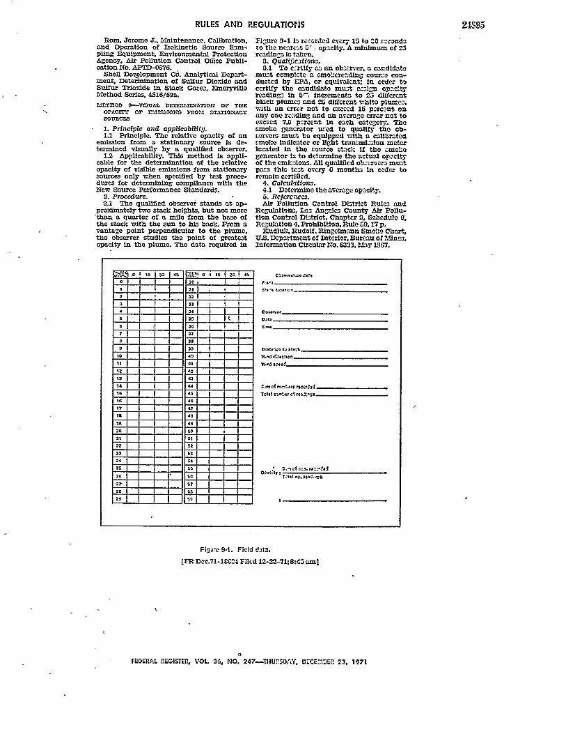
RULES AND REGULATIONS
Rom, Jerome J., Maintenance, Calibration,and Operation of Isokinetic Source Sam-pling Equipment, Environmental ProtectionAgency, Air Pollution Control OMce Publi-cation No. APTD-0576.
Shell Development C6. Analytical Depart-ment, Determination of Sulfur Dloxlde andSulfur Trloxlde In Stack Gases. EmeryvilleMethod Series, 4516/59a.
=I-THOD 9--VSUAL DETEaLIrATION OF THUEOPACfl' Or EMISSIONS 7MO15L STATIONARYSOURCES
1. Principle and applicability.1.1 Principle. The relative opacity of an
emission from a stationary source is de-termined visually by a qualified obzerver.
1.2 Applicability. This method is appli-cable for the determination of the relativeopacity of visible emissions from stationarysources only when specified by test proce-dures for determining compliance with theNew Source Performance Standardp.
2. Procedure.2.1 The qualified observer stands at ap-
proximately two stack heights, but not morethan a quarter of a mile from the base ofthe stack with the sun to his back. From avantage point perpendicular to the plume,the observer studies the point of greatestopacity in the plume. The data required in
Figjure 9-1 I recnrded every 15 to ^O cacondato the ncaret G , opacity. A minimum of 23readin~a Is taken.
3. Qualifications.3.1 To c~rtify a3 an obae-ver. a candidate
must complete a smo1:crcadlng cour-o con-ducted by EPA, or equivalcnt; in order tocertify the candidato must ac.in opacItyredings in ,* increment. to 23 differentblacl: plumes, and 25 different white plume,.with an error not to exccsd 15 parcent ouany one reading and an average error not toexceed 7.3 p=rcent In each category. Thesmohe generator uced to qualify the ob-cervers must be equipped with a calibratedsmol:e indicator or light tra=lon meterlocated in the rourco stack If the smohogenerator Is to determine the actual opacityof the emL-ions. Al qualfed obsarcra mustpacs this teot every 0 months In order toremain certUed.
4. Calculation.4.1 Determine the average opa ty.S. ReferercC3.Air Pollution Control DLItrict Rule and
Regulations, L3 Angeles County Air Pollu-tion Control Dstrict, Chapter 2. Scbedule 6,Regulation 4. Prohibition, Rule 10,17 p.
Kudiul, Rudolf, Pingelmman Smoke Chart,U.S. Department of Interior, Bureau of MInes.Information Circular 1,7o. 8333. ?May 19G7.
E. 0 15 is 45
0
I -2
5
6
78
9
10It
I I S
4
41
12 42 t13 43
14 44
15 45
16 46
17 41
1 40
19 420 5O21 51
22 52
23 63
24 54
25 t520 *" 50
2G 57
2r 52
29 10
1T -
TOlat 0 rotlaO
0 C1o Czto : =
Figare 9-1. Field data.
[FR Doc.71-18G24 Flied 12-22-71;8:45 aml
OFEDERS.L RlEGISTER., VOL 36, NO. 247-THUESAY, 0C E.IEf 23, 1971
24S95