1 - endo 2 - 1.1 linearmech linear actuators linearmech electromechanical linear actuators are...
TRANSCRIPT


- 1 -
1. The Product 1.1 Linearmech linear actuators ..................................................................................................page 2 1.2 Linearmech linear actuators range ........................................................................................page 3 1.3 Manufacturing features ...........................................................................................................page 5 1.4 Linear actuators selection criteria ...........................................................................................page 6 2. Acme screw linear actuators LMR Series LMR 01 DC motor .....................................................................................................................page 8 LMR 02 DC motor .....................................................................................................................page 10 LMR 03 DC motor .....................................................................................................................page 12 3. Acme screw linear actuators ATL Series ATL 02 AC or DC motor ...........................................................................................................page 14 ATL 05 DC motor .....................................................................................................................page 16 ATL 08 DC motor .....................................................................................................................page 18 ATL 10 AC motor .....................................................................................................................page 20 DC motor .....................................................................................................................page 22 ATL 12 AC motor .....................................................................................................................page 24 4. Acme screw linear actuators CLA Series CLA 20 AC or DC motor ...........................................................................................................page 26 CLA 25 AC motor .....................................................................................................................page 28 DC motor .....................................................................................................................page 30 CLA 25 S, CLA 25 M AC or DC motor .............................................................................................page 32 CLA 28 AC or DC motor ...........................................................................................................page 34 CLA 28 T AC or DC motor ...........................................................................................................page 36 5. Acme screw linear actuator LMI 02 DC motor ...............................................................................page 38 6. Acme screw linear actuator LMP 03 DC motor .............................................................................page 39 7. Acme screw linear actuator UAL 0 DC motor ................................................................................page 40 8. Ball screw linear actuators BSA Series BSA 08 DC motor .....................................................................................................................page 42 BSA 10 AC or DC motor ...........................................................................................................page 44 BSA 11 AC or DC motor ...........................................................................................................page 48 BSA 12 AC motor .....................................................................................................................page 52 9. Ball screw linear actuators CLB Series CLB 25 AC or DC motor ...........................................................................................................page 54 CLB 27 AC or DC motor ...........................................................................................................page 58 10. Ball screw linear actuator UBA 0 DC motor ...................................................................................page 60 11. Gearmotors for rotative actuators MR 15 DC motor .....................................................................................................................page 63 MR 31 DC motor .....................................................................................................................page 64 MR 40 FC DC motor .....................................................................................................................page 65 12. General Features 12.1 Ball screws ............................................................................................................................page 66 12.2 Static and dynamic self-locking conditions .............................................................................page 68 12.3 DC motors .............................................................................................................................page 69 12.4 AC motors .............................................................................................................................page 70 13. Stroke end switches and positioning control 13.1 Magnetic stroke end reed switches FCM for linear actuators ATL and BSA Series .................page 72 13.2 Electric stroke end switches FCE for linear actuators ATL and BSA Series .............................page 72 13.3 Electric stroke end switches FC for linear actuators LMR Series .............................................page 73 13.4 Electric stroke end switches and potentiometer FC+POR for linear actuators CLA Series ......page 74 13.5 Encoder GI .............................................................................................................................page 75 13.6 Encoder EH38 .......................................................................................................................page 75 14. Controls and drivers ......................................................................................................................page 76 14.1 LME 01 Electronic overload protection ..................................................................................page 76 14.2 LME 02 Electronic dynamic braking ......................................................................................page 77 14.3 LME 11 Single-actuator programmable driver .......................................................................page 78 14.4 LME 12 Two-actuators programmable driver ........................................................................page 79 15. Installation and Commissioning ..................................................................................................page 80
INDEX

- 2 -
1.1 LINEARMECH LINEAR ACTUATORS
Linearmech electromechanical linear actuators are motorized mechanical cylinders able to transform a rotary movement of a motor into a linear motion.
Able to work under push or pull load. Due to the mechanical resistance of their components, many actuators can support push loads higher than pull loads.
Their main characteristics are the high performance reliability, with or without load, and the low noise level.
Their installation is simple and not expansive: it requires just a front and rear hinging as for standard hydraulic and pneumatic cylinders.
They can effectively replace pneumatic and hydraulic cylinders being able to perform:
- Reliability in push-pull motion
- Accuracy in stopping position
- Position holding under load (self-locking)
- Energy consumption during operation only
- Easy installation; only power and control electrical cables are required
- High safety in load lifting (static self-locking and safety nut available)
- Safe operation even in very high or very low temperature conditions without risk of freezing or fire; electromechanical cylinders do not use air or oil under pressure
The wide range of sizes, stroke lengths, motor types, linear speeds and available accessories makes it easy to use these products not only in new applications but also to replace hydraulic and pneumatic cylinders, improving the solution in terms of performances and economical advantages.
Linearmech S.r.l. Technical Dpt. is available to carry out calculations, technical checks and norm certifications issue according to customer requirements.
The technical catalogue in PDF format and 3D/2D models of standard products selected with a configu-rator can be downloaded on our website www.linearmech.it. For customized products and dimensioned drawings, please contact: [email protected].
Linearmech S.r.l. offers:
§ Complete range of standard electromechanical linear actuators as per catalogue.
The mounting is carried out upon customer’s purchase order. All components are available on stock. This ensure very short delivery time and immediate availability in case of machine stop.
§ Customized electromechanical linear and rotative actuators.
The customization is carried out according to customer specific requirements. It can involve simple modifications of existing models up to the design and execution of completely tailor-made products, exclusively manufactured for a specific customer.
On request, products can be marked with customized label.
Linearmech electro-mechanical actuators are totally manufactured in Italy in the plant located in Anzola dell’Emilia (Bologna). All components used in the production are of Italian manufacture.
As a matter of fact, the entire product can be defined as “Made in Italy”, assuring a constant total quality, checked by professional and skilled personnel.

- 3 -
1.2 LINEARMECH ACTUATORS RANGE
Linearmech linear actuators range consists of two main product groups determined by their different linear drives: - Acme screw linear actuators; - Ball screw linear actuators.
LINEARMECH ELECTROMECHANICAL ACTUATORS
Acme screw LINEAR ACTUATORSDuty cycle
15% on 10 min30% on 10 min
Ball screw LINEAR ACTUATORSDuty cycle
50% on 10 min100% on 10 min
LMR 01 Fmax = 1300 N Vmax = 52 mm/sLMR 02 Fmax = 3000 N Vmax = 40 mm/sLMR 03 Fmax = 6000 N Vmax = 25 mm/s
ATL 02 Fmax = 2000 N Vmax = 48 mm/sATL 05 Fmax = 2500 N Vmax = 32 mm/sATL 08 Fmax = 4000 N Vmax = 150 mm/sATL 10 Fmax = 5000 N Vmax = 150 mm/sATL 12 Fmax = 11000 N Vmax = 93 mm/s
BSA 08 Fmax = 4000 N Vmax = 63 mm/sBSA 10 Fmax = 5000 N Vmax = 63 mm/sBSA 11 Fmax = 5000 N Vmax = 125 mm/sBSA 12 Fmax = 9000 N Vmax = 58 mm/s
CLA 20 Fmax = 2000 N Vmax = 48 mm/sCLA 25 Fmax = 5000 N Vmax = 100 mm/sCLA 25S Fmax = 5000 N Vmax = 100 mm/sCLA 25M Fmax = 5000 N Vmax = 100 mm/sCLA 28 Fmax = 10000 N Vmax = 8 mm/sCLA 28T Fmax = 10000 N Vmax = 8 mm/s
CLB 25 Fmax = 5000 N Vmax = 125 mm/sCLB 27 Fmax = 7000 N Vmax = 58 mm/s
LMI 02 Fmax = 750 N Vmax = 19 mm/sLMP 03 Fmax = 280 N Vmax = 190 mm/sUAL 0 Fmax = 390 N Vmax = 600 mm/s
UBA 0 Fmax = 420 N Vmax = 500 mm/s
GEARMOTORS for rotative actuators
MR 15 Mt = 3 Nm n = 520 rpmMR 31 Mt = 15 Nm n = 185 rpmMR 40FC Mt = 15 Nm n = 185 rpm

- 4 -
LMR SeriesAcme screw linear actuators, 3 sizes available. DC motor.Built-in adjustable stroke end switches activated by self-keeping commutation devices.Load capacity up to 6 000 N, linear speed up to 52 mm/s
ATL SeriesAcme screw linear actuators, 5 sizes available. DC or AC 1-phase or 3-phase motors.Adjustable stroke end magnetic reed switches and external adjustable stroke end electric switches.Load capacity up to 11 000 N, linear speed up to 150 mm/s
CLA SeriesAcme screw linear actuators, 6 sizes available. DC or AC 1-phase or 3-phase motors.Adjustable electric cam-operated stroke end switches fitted in closed box.Rotative potentiometer for positioning control.Load capacity up to 10 000 N, linear speed up to 100 mm/s
LMI 02 Acme screw linear actuator with compact cylindrical shape, small overall dimensions. DC motor. Max load 750 N, linear speed up to 20 mm/s
LMP 03Acme screw linear actuator with motor mounted parallel to actuator axis. DC motor.Max load 280 N, linear speed up to 190 mm/s
UAL 0Acme screw linear actuator, timing belts and pulleys transmission, with parallel motor design. DC motor.Adjustable stroke end magnetic reed switches.Max load 390 N, linear speed up to 600 mm/s
BSA SeriesBall screw linear actuators, 4 sizes available. DC or AC 1-phase or 3-phase motors. Motor brake available.Adjustable stroke end magnetic reed switches and external adjustable stroke end electric switches.Load capacity up to 9 000 N, linear speed up to 125 mm/s
CLB SeriesBall screw linear actuators, 2 sizes available. DC or AC 1-phase or 3-phase motors. Motor brake available.Adjustable electric cam-operated stroke end switches fitted in closed box.Rotative potentiometer for positioning control.Load capacity up to 7 000 N, linear speed up to 125 mm/s
UBA 0 Ball screw linear actuator, timing belts and pulleys transmission with motor mounted parallel to actuator axis.DC motor. Adjustable stroke end magnetic reed switches.Max. load 420 N, linear speed up to 500 mm/s
MR SeriesMotorgears for rotative actuators. DC motor. Bi-directional, incremental encoder with 2 output channelsAdjustable electric cam-operated stroke end switches. Rotative potentiometer single turn 5 kOhm.
1.2 LINEARMECH ACTUATORS RANGE

- 5 -
Linearmech linear actuators are totally manufactured in Italy and assembled in our plant located in Bologna. All materials used in the production are of Italian origin.
Methodical controls are carried out in-line during manufacturing process to monitor the production quality and functional checks are carried out on every finished assembled product to ensure the total quality and reliability of the final product.
Input drives§Worm gear, geometric design for high performances and efficiency. Worm shaft fitted or extracted directly on the electric motor shaft for a more compact and cost effective solution, allowing the integrated electric motor mounting on the actuator housing. Helical wormwheel in bronze EN 1982 – CuSn12-C or in plastic material and high resistance Delrin® 500
§ Timing pulleys UNI ISO 5294:1991 in aluminium for low inertia Timing belts UNI ISO 5296-1:1991
Housing§ Casting in aluminium alloy EN 1706 AC-AISi9T6 machined with CNC machinery to ensure a high precision level.§ Die casting in aluminium EN 1706 AC-AISi11Cu2(Fe) machined in the bearing housing.
Trapezoidal acme screws Tr profile ISO 2901 ... ISO 2904Material: steel C 43 (UNI 7847)Rolled and subjected to straightening process to ensure the regular alignment in operation and avoiding undesirable noises and loss of efficiency.Max pitch error ± 0.5 mm over 300 mm thread length
Bronze nuts Tr profile ISO 2901 ... ISO 2904Material: Bronze EN 1982 – CuAI9 Tr 1-start Bronze EN 1982 CuSn12 Tr 2 or 3 starts Delrin® 500Ball screwsRolled and hardened, manufactured by Servomech SpA S.U.Material: steel 42 CrMo 4 (UNI EN 10083)Precision Class ISO IT 7Max pitch error ± 0.5 mm over 300 mm thread length
Ball nutsManufactured by Servomech SpA S.U.Material: steel 18 NiCrMo 5 (UNI EN 10084)Hardened and groundMicrofinishingMax axial backlash (0.07 ÷ 0.08)Ball nut without play or pre-loaded on request
Push rods§Material: Chrome plated steel ST 52 DIN 2391 - tolerance on outer diameter f7§Anodized aluminium for small size actuators§Push rods in stainless steel AISI 304 on request
Outer protective tubes§ Drawn profiles in aluminium EN AW 6060 T5§Aluminium alloy tubes 6060 UNI 90005/1 anodizing 20 mm§Cold-drawn steel St 52.2 DIN 2391
Front and rear attachments Wide range of options: clevis ends and ball jointsBoth front and rear attachments are provided with self-lubricating bronze bushes to reduce frictions and sticking and to improve the efficiency (not available for small size actuators).
1.3 MANUFACTURING FEATURES

- 6 -
1.4 SELECTION CRITERIA
In order to select the most suitable linear actuator, it is first necessary to analyse the application to determine the required performances and the working conditions.
1. Basic performances required
§ Stroke
§ Push or pull load
§ Linear speed
1.1 The load and the linear speed, if considered separately, determine the required type of linear actuator to be selected; if considered as contemporaneous performances they determine the required power and, therefore, the actuator’s size.
1.2 The stroke length may influence the selection of the actuator’s size only in case of very long stroke lengths and high push loads; in such a case, the buckling resistance of the screw should be checked. For more details and support, please contact our Technical Dpt.
2. Working and duty cycle
The single working cycle and the total actuator’s duty cycle determine the choice of an actuator with acme screw or, alternatively, with ball screw.
The section “Performances and Features” states the duty cycle with max load admitted for each actuator.
The duty cycle, expressed in % over a 10 minutes period, is the percentage of time referred to 10 minu-tes, during which the actuator can operate under the maximum load conditions stated in this catalogue at (-10 ... +40) °C environment temperature.
Generally, the acme screw linear actuators can work with duty cycle of 15% or 30% over 10 minutes (depending on the electric motor type), while the ball screw linear actuators can work with duty cycle of 50% up to 100% (depending on the electric motor type).
For preliminary checks or any doubt concerning the selection, please contact our Technical Dpt.
3. Electric motor type
Depending on the series and the type, linear actuators are available with 12, 24 or 36 V DC motor or with AC 1-phase or 3-phase motor.
Some types of motors are available also with positioning or stopping brake.
The motors available for each actuator are stated in the specific section “Performances and Features” and in the table concerning the motors specifications at the end of this catalogue.

- 7 -
1.4 SELECTION CRITERIA
4. AccessoriesLinearmech linear actuators are supplied with a wide range of accessories as indicated in the specific section “Accessories” for each actuator size:
§ adjustable stroke end limit switches
§incremental bi-directional encoders with 2 output channels
§analogic rotative potentiometer
§ brake motor
§ overload electronic protection
§ dynamic overload mechanical protection
§ many type of front attachments
§rear fixing supports
§ stainless steel push rod
§ electronic dynamic braking device
§ programmable drivers
5. Working environment conditions
The external environment conditions in which the actuator is working are particularly important and shall be considered and evaluated, since they may strongly influence the regular functioning and the lifetime of the linear actuator.
The standard equipment of the linear actuators as well as the stated protection level against water and dust, are sufficient to enable the regular functioning in the main industrial applications.
Nevertheless, we recommend to report particular working environment conditions such as:
§Outside use, without proper auxiliary protections;
§Environment temperature lower than -10 °C or higher than +40 °C;
§Dusty environment and with polluting substances;
§Environments which require strong washing with acid or basic solutions;
§Use with strong external induced vibrations.
Finally, we are convinced that there is always a solution to any problem; what is important is to highlight and to analyze the problem in advance.
Our Technical Dpt. is available to evaluate with you the best technical and economical solution.

- 8 -
LMR 01ACME SCREW LINEAR ACTUATOR
OVERALL DIMENSIONS
STROKE CODE
STROKE [mm]
LENGTHMASS [kg]
Lc [mm] La [mm]
C50 50 140 190 0.85
C100 100 190 290 1.10
C150 150 240 390 1.25
C200 200 290 490 1.40
C250 250 340 590 1.55
C300 300 390 690 1.70
PERFORMANCES AND FEATURES§Pull-Push load up to 1 300 N§Linear speed up to 52 mm/s§Standard stroke lengths: 50, 100, 150, 200, 250, 300 mm (min. stroke limited by FC switches: 50 mm) (for different / longer stroke lengths please contact us)§Aluminium housing and rear attachment§Anodized aluminium push rod – tolerance f8§Aluminium front attachment §12, 24 or 36 V DC motor with electromagnetic noise suppressor (motor features details on page 69)§Duty cycle with max load: 15% over 10 min at (-10 ... +40) °C§Standard motor mounting position as per dimensional drawing (right-hand, code RH)§Standard protection IP65 - Test IP6X according to EN 60529 §12 §13.4-13.6 - Test IPX5 according to EN 60529 §14.2.5 (tests made with not running actuator)§Long-life lubrication, maintenance free
ACCESSORIES§Stainless steel push rod (code SS)§Two adjustable built-in stroke end switches (code FC2)§Two adjustable built-in stroke end switches, switching off the motor (code FC2X)§Extra switch for intermediate position (code FC)§2-channels incremental encoder on motor shaft 1 ppr (code GI 21) 4 ppr (code GI 24) (wiring diagrams on page 75)
Number of pulses for 100 mm stroke
RatioRN2 RN1 RL2 RL1
GI 21 192 383 483 967GI 24 767 1 533 1 933 3 867
Stroke Lc
La = Lc + Stroke
Motor cable length 0.3 m
T
(mot
or w
ith e
ncod
er)
Length Stroke £ 300 mm Stroke > 300 mm
Lc [mm] 90 + Stroke 140 + Stroke
T [mm] 78 + Stroke 128 + Stroke
OPTIONS§Motor mounting position on opposite side (left-hand, code LH)§Fixing attachment turned at 90° (code RPT 90)

- 9 -
LMR 01ACME SCREW LINEAR ACTUATOR
PERFORMANCES with 24 V DC motor(Performances with 12 V DC motor: same load, linear speed 10 % less, electrical consumption 2 times more)
1-start acme screw Tr 12×3
2-starts acme screw Tr 12×6 (P3)
Load [N]
Load [N]
Load [N]
Load [N]
Spe
ed [m
m/s
]S
peed
[mm
/s]
Cur
rent
[A]
Cur
rent
[A]
DC 24 V
DC 24 V
DC 24 V
DC 24 V
Self-locking conditionsInformation about statically self-locking conditions with pull or push load on page 68.
ORDERING CODE EXAMPLE
LMR 01 RL1 C200 CC 24 V FC2
ActuatorSelected
ratioRequired
strokeMotor
Stroke end switches
Accessories Options

- 10 -
LMR 02
STROKE CODE
STROKE [mm]
LENGTH MASS [kg]Lc [mm] La [mm]
C50 50 180 230 2
C100 100 230 330 2.3
C150 150 280 430 2.45
C200 200 330 530 2.6
C250 250 380 630 2.75
C300 300 430 730 2.9
C400 400 580 980 3.2
PERFORMANCES AND FEATURES§Pull-Push load up to 3 000 N§Linear speed up to 41 mm/s§Standard stroke lengths: 50, 100, 150, 200, 250, 300, 400 mm (min. stroke limited by FC switches: 50 mm) (for different / longer stroke lengths please contact us)§Aluminium housing and rear attachment §Chrome-plated steel push rod §Stainless steel AISI 303 front attachment §12, 24 or 36 V DC motor with electromagnetic noise suppressor (motor features details on page 69)§Duty cycle with max. load: 15% over 10 min at (-10 ... +40) °C§Standard motor mounting position as per dimensional drawing (right-hand, code RH)§Standard protection IP65 - Test IP6X according to EN 60529 §12 §13.4-13.6 - Test IPX5 according to EN 60529 §14.2.5 (tests made with not running actuator)§Long-life lubrication, maintenance free
Length Stroke £ 300 mm Stroke > 300 mm
Lc [mm] 130 + Stroke 180 + Stroke
T [mm] 107 + Stroke 157 + Stroke
OPTIONS§Motor mounting position on opposite side (left-hand, code LH)§Fixing attachment turned at 90° (code RPT 90)
ACCESSORIES§Stainless steel push rod (code SS)§Two adjustable built-in stroke end switches (code FC2)§Two adjustable built-in stroke end switches, switching off the motor (code FC2X)§Extra switch for intermediate position (code FC))§2-channels incremental encoder on motor shaft: 1 ppr (code GI 21) 4 ppr (code GI 24) (wiring diagrams on page 75)
Number of pulses for 100 mm stroke
RatioRN2 RN1 RL2 RL1
GI 21 246 492 775 1550GI 24 984 1968 3100 6200
ACME SCREW LINEAR ACTUATOR
OVERALL DIMENSIONS
Stroke Lc
La = Lc + Stroke
Motor cable length 0.3 m
T
(with
enc
oder
)

- 11 -
LMR 02ACME SCREW LINEAR ACTUATOR
ORDERING CODE EXAMPLE
LMR 02 RL1 C200 CC 24 V FC2
ActuatorSelected
ratioRequired
strokeMotor
Stroke end switches
Accessories Options
Self-locking conditionsInformation about statically self-locking conditions with pull or push load on page 68.
1-start acme screw Tr 14×4
2-starts acme screw Tr 14×8 (P4)
PERFORMANCES with 24 V DC motor(Performances with 12 V DC motor: same load, linear speed 10 % less, electrical consumption 2 times more)
Load [N]
Load [N]
Load [N]
Load [N]
Spe
ed [m
m/s
]S
peed
[mm
/s]
Cur
rent
[A]
Cur
rent
[A]
DC 24 V
DC 24 V
DC 24 V
DC 24 V

- 12 -
LMR 03
Ø56
STROKE CODE
STROKE [mm]
LENGTH MASS [kg]Lc [mm] La [mm]
C100 100 230 330 2.6C150 150 280 430 2.9C200 200 330 530 3.2C250 250 380 630 3.5C300 300 430 730 3.8C400 400 580 980 4.7C500 500 680 1180 5.3
PERFORMANCES AND FEATURES§Pull-Push load up to 6 000 N§Linear speed up to 25 mm/s§Standard stroke lengths: 100, 150, 200, 250, 300, 400, 500 mm (min. stroke limited by FC switches: 50 mm) (for different / longer stroke lengths please contact us)§Aluminium housing and rear attachment §Chrome-plated steel push rod – tolerance f7§Stainless steel AISI 303 front attachment §12, 24 or 36 V DC motor with electromagnetic noise suppressor (motor features details on page 69)§Duty cycle with max. load: 15% over 10 min at (-10 ... +40) °C§Standard motor mounting position as per dimensional drawing (right-hand, code RH)§Standard protection IP65 - Test IP6X according to EN 60529 §12 §13.4-13.6 - Test IPX5 according to EN 60529 §14.2.5 (tests made with not running actuator)§Long-life lubrication, maintenance free
ACCESSORIES§Stainless steel push rod (code SS)§Two adjustable built-in stroke end switches (code FC2)§Two adjustable built-in stroke end switches, switching off the motor (code FC2X)§Extra switch for intermediate position (code FC)§2-channels incremental encoder on motor shaft 1 ppr (code GI 21) 4 ppr (code GI 24) (wiring diagrams on page 75)
Number of pulses for 100 mm stroke
RatioRN2 RN1 RL2 RL1
GI 21 325 650 862 1 725GI 24 1 300 2 600 3 450 6 900
Length Stroke £ 300 mm Stroke > 300 mm
Lc [mm] 130 + Stroke 180 + Stroke
T [mm] 113 + Stroke 163 + Stroke
OPTIONS§Motor mounting position on opposite side (left-hand, code LH)§Fixing attachment turned at 90° (code RPT 90)
ACME SCREW LINEAR ACTUATOR
Stroke Lc
La = Lc + Stroke
T
Motor cable length 0.3 m
( mot
or w
ith e
ncod
er)
OVERALL DIMENSIONS

- 13 -
LMR 03ACME SCREW LINEAR ACTUATOR
Self-locking conditionsInformation about statically self-locking conditions with pull or push load on page 68.
ORDERING CODE EXAMPLE
LMR 03 RL1 C200 CC 24 V FC2
ActuatorSelected
ratioRequired
strokeMotor
Stroke end switches
Accessories Options
1-start acme screw Tr 16×4
2-starts acme screw Tr 16×8 (P4)
Load [N]
Load [N]
Load [N]
Load [N]
Spe
ed [m
m/s
]S
peed
[mm
/s]
Cur
rent
[A]
Cur
rent
[A]
DC 24 V
DC 24 V
DC 24 V
PERFORMANCES with 24 V DC motor(Performances with 12 V DC motor: same load, linear speed 10 % less, electrical consumption 2 times more)
DC 24 V

- 14 -
ATL 02
LcT
PERFORMANCES AND FEATURES§ Pull-Push load up to 2 000 N§Linear speed up to: 48 mm/s (DC motor) 30 mm/s (AC motor)§Standard stroke lengths: 100, 150, 200, 300 mm (for different / longer stroke lengths please contact us)§Aluminium alloy housing and rear attachment, with bronze bush §Anodized aluminium outer tube§Anodized aluminium push rod – tolerance h8§Stainless steel AISI 303 front attachment §Motors: (motor features details on page 69 and 70) - 12 or 24 V DC motor with permanent magnets - AC 3-phase or 1-phase motor§Duty cycle with max load: - DC motor max.15% over 10 min at (-10 ... +40) °C - AC motor max.30% over 10 min at (-10 ... +40) °C§Standard motor mounting position as per sketch (right-hand, code RH)
La =Lc + StrokeStroke
STROKE CODE
STROKE[mm]
LENGTH T [mm]
MASS with DC motor [kg]
MASS with AC motor [kg]Lc [mm] La [mm]
C100 100 243 343 225 1.35 3.20
C150 150 293 443 275 1.60 3.45
C200 200 343 543 325 1.85 3.70
C300 300 443 743 425 2.10 3.95
Stroke end reed switches FCM
Motor cable length 0.3 m
Capacitor
Actuator with AC 1-phase or 3-phase motor
Actuator with DC motor
§Standard protection: - with DC motor IP65 Test IP6X according to EN 60529 §12 §13.4-13.6 Test IPX5 according to EN 60529 §14.2.5 - with AC motor IP55 (tests made with not running actuator)§Long-life lubrication, maintenance free
ACCESSORIES§Stainless steel push rod (code SS)§Rear bracket (code SP)§Two adjustable stroke end reed switches (code FCM)§Extra switches for intermediate positions
OPTIONS§Motor mounting position on opposite side (left-hand, code LH)§Fixing attachment turned at 90° (code RPT 90)
Length Stroke £ 300 mm Stroke > 300 mm
Lc [mm] 143 + Stroke 158 + Stroke
T [mm] 125 + Stroke 125 + Stroke
Rear bracket
SP
ACME SCREW LINEAR ACTUATOR
OVERALL DIMENSIONS
Pin

- 15 -
ATL 02
PERFORMANCES with AC 3-phase 50 Hz 230/400 V or 1-phase 50 Hz 230 V motor
Load [N]
Load [N]
Load [N]
Load [N]
1-start acme screw Tr 13.5×3
0.06 kW - 2 pole motor
RATIO LOAD [N] SPEED [mm/s]
RN1 1500 11RL1 2000 5.5
2-starts acme screw Tr 14×8 (P4)
0.06 kW - 2 pole motor
RATIO LOAD [N] SPEED [mm/s]
RN2 1000 30RL2 1100 15
Spe
ed [m
m/s
]S
peed
[mm
/s]
Cur
rent
[A]
Cur
rent
[A]
1-start acme screw Tr 13.5×3
2-starts acme screw Tr 14×8 (P4)
PERFORMANCES with 24 V DC motor(Performances with 12 V DC motor: same load, linear speed 10 % less, electrical consumption 2 times more)
ACME SCREW LINEAR ACTUATOR
Self-locking conditionsInformation about statically self-locking conditions with pull or push load on page 68.
ORDERING CODE EXAMPLE
ATL 02 RL1 C200 CC 24 V FCM
ActuatorSelected
ratioRequired
strokeMotor
Stroke end switches
Accessories Options

- 16 -
ATL 05
PERFORMANCES AND FEATURES§Pull-Push load up to 2 500 N§Linear speed up to 32 mm/s§Standard stroke lengths: 100, 150, 200, 300 mm (for different / longer stroke lengths please contact us)§Aluminium alloy housing and rear attachment, with bronze bush §Anodized aluminium outer tube§Anodized aluminium push rod – tolerance h8§Stainless steel AISI 303 front attachment §12, 24 or 36 V DC motor with electromagnetic noise suppressor (motor features details on page 69)§Duty cycle with max load: 15% over 10 min at (-10 ... +40) °C§Standard motor mounting position as per sketch (right-hand, code RH)
Lc
T
La =Lc + Stroke
Stroke
Motor cable length 0.3 m
Length Stroke £ 300 mm Stroke > 300 mm
Lc [mm] 143 + Stroke 158 + Stroke
T [mm] 125 + Stroke 125 + Stroke
Pin
Rear bracket
SP
§Standard protection IP65 - Test IP6X according to EN 60529 §12 §13.4-13.6 - Test IPX5 according to EN 60529 §14.2.5 (tests made with not running actuator)§Long-life lubrication, maintenance free
ACCESSORIES§Stainless steel push rod (code SS)§Rear bracket (code SP)§Two adjustable stroke end reed switches (code FCM)§Extra switches for intermediate positions
OPTIONS§Motor mounting position on opposite side (left-hand, code LH)§Fixing attachment turned at 90° (code RPT 90)
ACME SCREW LINEAR ACTUATOR
Stroke end reed switches FCM
STROKE CODE
STROKE[mm]
LENGTH T [mm]
MASS [kg]Lc [mm] La [mm]
C100 100 243 343 225 2.00
C150 150 293 443 275 2.25
C200 200 343 543 325 2.50
C300 300 443 743 425 2.75
OVERALL DIMENSIONS

- 17 -
ATL 05
1-start acme screw Tr 13.5×3
2-starts acme screw Tr 14×8 (P4)
Spe
ed [m
m/s
]S
peed
[mm
/s]
Load [N]
Load [N]
Load [N]
Load [N]
Cur
rent
[A]
Cur
rent
[A]
PERFORMANCES with 24 V DC motor(Performances with 12 V DC motor: same load, linear speed 10 % less, electrical consumption 2 times more)
ACME SCREW LINEAR ACTUATOR
Self-locking conditionsInformation about statically self-locking conditions with pull or push load on page 68.
ORDERING CODE EXAMPLE
ATL 05 RL1 C200 CC 24 V FCM
ActuatorSelected
ratioRequired
strokeMotor
Stroke end switches
Accessories Options

- 18 -
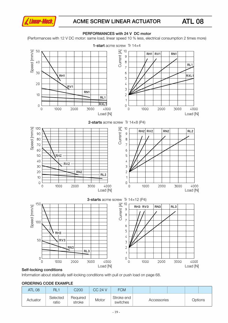
ATL 08
PERFORMANCES AND FEATURES§Pull-Push load up to 4 000 N§Linear speed up to 150 mm/s§Standard stroke lengths: 100, 150, 200, 300, 400, 500 mm (for different / longer stroke lengths please contact us)§Aluminium alloy housing and rear attachment, with bronze bush §Anodized aluminium outer tube§Chrome-plated steel push rod – tolerance f7§Stainless steel AISI 303 front attachment §12, 24 or 36 V DC motor with electromagnetic noise suppressor (motor features details on page 69)§Duty cycle with max. load: 15% over 10 min at (-10 ... +40) °C§Standard motor mounting position as per sketch (right-hand, code RH)§Standard protection IP65 - Test IP6X according to EN 60529 §12 §13.4-13.6 - Test IPX5 according to EN 60529 §14.2.5 (tests made with not running actuator)§Long-life lubrication, maintenance free
Lc
T
La =Lc + Stroke
Stroke
Motor cable length 0.3 m
Pin
Length with FCE with FCM
Lc [mm] 166 + Stroke 220 + Stroke
T [mm] 139 + Stroke 166 + Stroke
Rear bracket
SP
ACCESSORIES§Stainless steel push rod (code SS)§Mechanical overload protection: safety clutch (code FS)§Rear bracket (code SP)§Two adjustable stroke end reed switches (code FCM)§Extra switches for intermediate positions
OPTIONS§Motor mounting position on opposite side (left-hand, code LH)§Fixing attachment turned at 90° (code RPT 90)
ACME SCREW LINEAR ACTUATOR
Stroke end reed switches FCM
STROKE CODE
Actuator without FCM Actuator with FCMT
[mm]MASS
[Kg]STROKE[mm]
LENGTH STROKE[mm]
LENGTHLc [mm] La [mm] Lc [mm] La [mm]
C100 100 266 366 73 293 366 239 3.5
C150 150 316 466 123 343 466 289 3.7
C200 200 366 566 173 393 566 339 3.8
C300 300 466 766 273 493 766 439 4.1
C400 400 566 966 373 593 966 539 4.4
C500 500 666 1166 473 693 1166 639 4.7
OVERALL DIMENSIONS
- 19 -
ATL 08
Load [N]
Load [N]
Load [N]
Load [N]
Load [N]
Load [N]
Spe
ed [m
m/s
]S
peed
[mm
/s]
Spe
ed [m
m/s
]
Cur
rent
[A]
Cur
rent
[A]
Cur
rent
[A]
1-start acme screw Tr 14×4
2-starts acme screw Tr 14×8 (P4)
3-starts acme screw Tr 14×12 (P4)
PERFORMANCES with 24 V DC motor(Performances with 12 V DC motor: same load, linear speed 10 % less, electrical consumption 2 times more)
ACME SCREW LINEAR ACTUATOR
Self-locking conditionsInformation about statically self-locking conditions with pull or push load on page 68.
ORDERING CODE EXAMPLE
ATL 08 RL1 C200 CC 24 V FCM
ActuatorSelected
ratioRequired
strokeMotor
Stroke end switches
Accessories Options

- 20 -
80
FR
ON
T A
TTA
CH
ME
NT
Lc
T
La =Lc + Stroke
Stroke
dept
h 17
(bra
ke m
otor
)
Pin
BALL JOINT
TS
CLEVIS END
FO
ROD END
ROE
FLANGE END
FL
Capacitor
166 + stroke
with FCE 181 + stroke
with FCM 220 + stroke
Length w/o and with FCE with FCM
Lc [mm] 166 + Corsa 220 + Corsa
T [mm] 139 + Corsa 166 + Corsa
Standard head with threaded hollow bore
BA
Rear bracket
SP
144 + Stroke
Stroke end electric switches FCE
89 + Stroke
ACME SCREW LINEAR ACTUATOR ATL 10 AC motor
Stroke end reed switches FCM
FCE cable length 1.5 m
STROKE CODE C100 C150 C200 C300 C400 C500Working stroke length w/o and with FCE [mm] 100 150 200 300 400 500
Working stroke length with FCM [mm] 73 123 173 273 373 473Ø
5.5
(4 b
ores
at 9
0°)
OVERALL DIMENSIONS

- 21 -
PERFORMANCES AND FEATURES§ Push load up to 5 000 N§Pull load up to 4 000 N§Linear speed up to 140 mm/s§Standard stroke lengths: 100, 150, 200, 300, 400, 500 mm (for different / longer stroke lengths please contact us)§Aluminium alloy housing and rear attachment, with bronze bush §Anodized aluminium outer tube§Chrome-plated steel push rod – tolerance f7§Standard head BA or rod end ROE in stainless steel AISI 303 with bronze bush§AC 3-phase or 1-phase motor (motor features details on page 70)§Duty cycle with max load: 30% over 10 min at (-10...+40) °C§Standard protection IP55 (IP54 with brake)§Standard motor mounting position as per sketch (right-hand, code RH)§Long-life lubrication, maintenance free
1-start acme screw Tr 14×4
RATIO0.09 kW - 4 pole motor 0.12 kW - 2 pole motor
LOAD [N] SPEED [mm/s] LOAD [N] SPEED [mm/s]
RH1 1750 23 1250 47
RV1 2620 15 1860 30
RN1 4490 7.5 3230 15
RL1 5000 3.5 5000 7.5
RXL1 5000 2 5000 3.5
2-starts acme screw Tr 14×8 (P4)
RATIO0.09 kW - 4 pole motor 0.12 kW - 2 pole motor
LOAD [N] SPEED [mm/s] LOAD [N] SPEED [mm/s]
RH2 1070 47 790 93
RV2 1620 30 1180 60
RN2 2880 15 2080 30
RL2 4800 7.5 3520 15
3-starts acme screw Tr 14×12 (P4)
RATIO0.09 kW - 4 pole motor 0.12 kW - 2 pole motor
LOAD [N] SPEED [mm/s] LOAD [N] SPEED [mm/s]
RH3 800 70 560 140
RV3 1210 45 860 90
RN3 2190 22 1540 45
RL3 3680 11 2680 22
PERFORMANCES with AC 3-phase 50 Hz 230/400 V or 1-phase 50 Hz 230 V motor
ACCESSORIES§ Different front attachments§Stainless steel push rod (code SS)§Rear bracket (code SP)§Mechanical overload protection, safety clutch (code FS)§Brake motor§Two adjustable stroke end reed switches (code FCM)§Extra switches for intermediate positions§Electromechanical stroke end switch for linear speed up to 30 mm/s (code FCE) (technical data on page 72)
OPTIONS§Motor mounting position on opposite side (left-hand, code LH)§Fixing attachment turned at 90° (code RPT 90)
ACME SCREW LINEAR ACTUATOR ATL 10 AC motor
Self-locking conditionsInformation about statically self-locking conditions with pull or push load on page 68.
ORDERING CODE EXAMPLE
ATL 10 RL1 C200 CA 230/400 V FCM
ActuatorSelected
ratioRequired
strokeMotor
Stroke end switches
Accessories Options

- 22 -
OVERALL DIMENSIONS
Lc
T
La =Lc + Stroke
Stroke
Pin
(bra
ke m
otor
)
(mot
or w
ith e
ncod
er)
Rear bracket
SP
Length w/o and with FCE with FCM
Lc [mm] 166 + Stroke 220 + Stroke
T [mm] 139 + Stroke 166 + Stroke
dept
h 17
144 + Stroke
89 + Stroke
ATL 10 DC motorF
RO
NT
AT
TAC
HM
EN
T
166 + stroke
with FCE 181 + stroke
with FCM 220 + stroke
FCE cable length 1.5 m
STROKE CODE C100 C150 C200 C300 C400 C500Working stroke length w/o and with FCE [mm] 100 150 200 300 400 500
Working stroke length with FCM [mm] 73 123 173 273 373 473Ø
5.5
(4 b
ores
at 9
0°)
ACME SCREW LINEAR ACTUATOR
Standard head with threaded hollow bore
BA
Stroke end electric switches FCE
BALL JOINT
TS
CLEVIS END
FO
ROD END
ROE
FLANGE END
FL
Stroke end reed switches FCM

- 23 -
PERFORMANCES AND FEATURES§ Pull-Push load up to 4 000 N§Linear speed up to 150 mm/s§Standard stroke lengths: 100, 150, 200, 300, 400, 500 mm (for different / longer stroke lengths please contact us)§Aluminium alloy housing and rear attachment, with bronze bush §Anodized aluminium outer tube§Chrome-plated steel push rod – tolerance f7§Standard head BA or rod end ROE in stainless steel AISI 303 with bronze bush§DC 12 or 24 V motor (motor features details on page 69)§Duty cycle with max load: 30% over 10 min at (-10 ... +40) °C§Standard protection IP54§Standard motor mounting position as per sketch (right-hand, code RH)§Long-life lubrication, maintenance free
3-starts acme screw Tr 14×12 (P4)
RATIO LOAD [N] SPEED [mm/s] CURRENT [A]
RH3 310 150 4
RV3 470 96 4
RN3 840 48 4
RL3 1430 24 4
2-starts acme screw Tr 14×8 (P4)
RATIO LOAD [N] SPEED [mm/s] CURRENT [A]
RH2 430 100 4
RV2 650 64 4
RN2 1160 32 4
RL2 1970 16 4
1-start acme screw Tr 14×4
RATIO LOAD [N] SPEED [mm/s] CURRENT [A]
RH1 680 50 4
RV1 1020 32 4
RN1 1770 16 4
RL1 2960 8 4
RXL1 4000 4 4
PERFORMANCES with 24 V DC motor(Performances with 12 V DC motor: same load, linear speed 10 % less, electrical consumption 2 times more)
ACCESSORIES§ Different front attachments§Stainless steel push rod (code SS)§Rear bracket (code SP)§Mechanical overload protection: safety clutch (code FS)§Brakemotor§Bi-directional incremental encoder, 100 ppr with zero set pulse, Push-Pull, 8÷24 Vdc (code EH38)§Two adjustable stroke end reed switches (code FCM)§Extra switches for intermediate positions§Electromechanical stroke end switch for linear speed up to 30 mm/s (code FCE) (technical data on page 72)
OPTIONS§Motor mounting position on opposite side (left-hand, code LH)§Fixing attachment turned at 90° (code RPT 90)
ORDERING CODE EXAMPLE
ATL 10 RL1 C200 CC 24 V FCM
ActuatorSelected
ratioRequired
strokeMotor
Stroke end switches
Accessories Options
ATL 10 DC motorACME SCREW LINEAR ACTUATOR
Self-locking conditionsInformation about statically self-locking conditions with pull or push load on page 68.

- 24 -
ATL 12
OVERALL DIMENSIONS
FR
ON
T A
TTA
CH
ME
NT
Lc
T
La =Lc + Stroke
Stroke
PinCapacitor
Lenght Stroke £ 300 mm Stroke > 300 mm
Lc [mm] 232 + Stroke 247 + Stroke
T [mm] 206 + Stroke 206 + Stroke
Q [mm] 252 267
Ø 6
.5 (4
bor
es a
t 90°
)
dept
h 17
Rear bracket
SP
148 + Stroke
89 + Stroke
ACME SCREW LINEAR ACTUATOR
(bra
ke m
otor
)
Lc =Q + Stroke
Standard head with threaded hollow bore
BA
Stroke end reed switches FCM
FCE cable length 1.5 m
Stroke end electric switches FCE
BALL JOINT
TS
CLEVIS END
FO
ROD END
ROE
FLANGE END
FL

- 25 -
ATL 12
1-start acme screw Tr 18×4
RATIO0.18 kW - 4 pole motor 0.25 kW - 2 pole motor
LOAD[N]
SPEED[mm/s]
LOAD[N]
SPEED[mm/s]
RV1 3130 23 2450 47
RN1 9620 5.5 7320 11
RL1 11000 2.5 11000 5.5
2-starts acme screw Tr 18×8 (P4)
RATIO0.18 kW - 4 pole motor 0.25 kW - 2 pole motor
LOAD[N]
SPEED[mm/s]
LOAD[N]
SPEED[mm/s]
RV2 2070 47 1590 93
RN2 6710 11 4500 22
RL2 10280 5.5 7660 11
PERFORMANCES AND FEATURES§ Push load up to 11 000 N§Pull load up to 8 000 N§Linear speed up to 93 mm/s§Standard stroke lengths: 100, 150, 200, 300, 400, 500, 600, 700, 800 mm (for different /longer stroke lengths please contact us)§Aluminium alloy housing and rear attachment, with bronze bush §Anodized aluminium outer tube§Chrome-plated steel push rod – tolerance f7§Standard front head BA or rod end ROE in stainless steel AISI 303 with bronze bush§AC 3-phase or 1-phase motor (motor features on page 70)§Standard protection IP55 (IP54 with brake)§Duty cycle with max load: 30% over 10 min at (-10 ... +40) °C§Standard motor mounting position as per sketch (right-hand, code RH)§Long-life lubrication, maintenance free
ACCESSORIES§ Different front attachments§Stainless steel push rod (code SS)§Rear bracket (code SP)§Mechanical overload protection: safety clutch (code FS)§Brake motor§Two adjustable stroke end reed switches (code FCM)§Extra switches for intermediate positions§Electro-mechanical stroke end switch for linear speed up to 30 mm/s (code FCE) (technical data on page 72)
OPTIONS§Motor mounting position on opposite side (left-hand, code LH)§Fixing attachment turned at 90° (code RPT 90)
ORDERING CODE EXAMPLE
ATL 12 RL1 C200 CA 230/400 V FCM
ActuatorSelected
ratioRequired
strokeMotor
Stroke end switches
Accessories Options
ACME SCREW LINEAR ACTUATOR
PERFORMANCES with AC 3-phase 50 Hz 230/400 V or 1-phase 50 Hz 230 V motor
Self-locking conditionsInformation about statically self-locking conditions with pull or push load on page 68.

- 26 -
CLA 20
PERFORMANCES AND FEATURES§ Pull-Push load up to 2 000 N§Linear speed up to 48 mm/s (DC motor)§Linear speed up to 30 mm/s (AC motor)§Standard stroke lengths: 100, 150, 200, 250, 300 mm (for different / longer stroke lengths please contact us)§Aluminium alloy housing and rear attachment §Anodized aluminium outer tube§Anodized aluminium push rod – tolerance h8§Rear attachment: - A1 zinc-plated steel - A2 aluminium alloy with bronze bush §Stainless steel AISI 303 front attachment §Motors: (motor features details on page 69 and 70) - 12 or 24 V DC motor with permanent magnets - AC 3-phase or 1-phase motor §Duty cycle with max load: - DC motor max.15% over 10 min at (-10 ... +40) °C - AC motor max.30% over 10 min at (-10 ... +40) °C§Standard protection: - with DC motor IP65 Test IP6X according to EN 60529 §12 §13.4-13.6 Test IPX5 according to EN 60529 §14.2.5 (tests made with not running actuator) - with AC motor IP55
Attachment A1 Attachment A2
Lc Lc
T T
La =Lc + Stroke La =Lc + Stroke
FC switchesand potentiometer
Stroke
Motor cable length 0.3 m
Pin
LengthActuator with
Attachment A1Actuator with
Attachment A2
Lc [mm] 142 + Stroke 150 + Stroke
T [mm] 129 + Stroke 136 + Stroke
Rear bracket
SP
§ Standard motor mounting position as per sketch (right-hand, code RH)§ Long-life lubrication, maintenance free
ACCESSORIES§Stainless steel push rod (code SS)§Rear bracket (code SP) with rear attachment A2§Adjustable electric stroke end switches (code FC2)§Adjustable electric stroke end switches, switching off the motor (not available with AC 3-phase motor) (code FC2X)§Extra switch for intermediate position (code FC)§Rotative potentiometer 5kOhm for positioning control (code POR5K)
NOTE: Extra limit switch and rotative potentiometer cannot be selected together
OPTIONS§Motor mounting position on opposite side (left-hand, code LH)§Fixing attachment turned at 90° (code RPT 90)
ACME SCREW LINEAR ACTUATOR
OVERALL DIMENSIONS

- 27 -
CLA 20
1-start acme screw Tr 13.5×3
0.06 kW - 2 pole motor
RATIOLOAD
[N]SPEED[mm/s]
RN1 1500 11
RL1 2000 5.5
2-starts acme screw Tr 14×8 (P4)
0.06 kW - 2 pole motor
RATIOLOAD
[N]SPEED[mm/s]
RN2 1000 30
RL2 1100 15
Load [N] Load [N]
Spe
ed [m
m/s
]S
peed
[mm
/s]
Cur
rent
[A]
2-starts acme screw Tr 14×8 (P4)
Load [N] Load [N]
Cur
rent
[A]
1-start acme screw Tr 13.5×3
Capacitor
ORDERING CODE EXAMPLE
CLA 20 RL1 C200 CC 24 V FC2 POR 5K
ActuatorSelected
ratioRequired
strokeMotor
Stroke end switches
Accessories Options
ACME SCREW LINEAR ACTUATOR
PERFORMANCES with AC 3-phase 50 Hz 230/400 V or 1-phase 50 Hz 230 V motor
PERFORMANCES with 24 V DC motor(Performances with 12 V DC motor: same load, linear speed 10 % less, electrical consumption 2 times more)
Self-locking conditionsInformation about statically self-locking conditions with pull or push load on page 68.

- 28 -
FR
ON
T A
TTA
CH
ME
NT
Lc Lc
1
2
T T
La =Lc + Stroke La = Lc + Stroke
Stroke
Pin
Capacitor
1. STROKE END SWITCHES BOX AND POTENTIOMETER2. MOTOR SHAFT EXTENSION for: Emergency manual activation Stroke end switches and potentiometer adjustment
(bra
ke m
otor
)
dept
h 17Rear
bracket
SP
Attachment A1 Attachment A2
CLA 25 AC motor
STROKE CODE
Actuator - Attachment A1STROKE
[mm]LENGTH T
[mm]Lc [mm] La [mm]
C100 100 290 390 273
C200 200 390 590 373
C300 300 490 790 473
Actuator - Attachment A2MASS
[Kg]STROKE[mm]
LENGTH T [mm]Lc [mm] La [mm]
100 297 397 280 5.3
200 397 597 380 5.6
300 497 797 480 5.9
Lc = Q + Stroke
Q[mm]
Attachment A1 Attachment A2195 202
ACME SCREW LINEAR ACTUATOR
OVERALL DIMENSIONS
Standard head with threaded hollow bore
BA
BALL JOINT
TS
CLEVIS END
FO
ROD END
ROE

- 29 -
PERFORMANCES AND FEATURES§ Push load up to 5 000 N§Pull load up to 4 000 N§Linear speed up to 93 mm/s§Standard stroke lengths: 100, 150, 200, 250, 300 mm (for different / longer stroke lengths please contact us)§Aluminium alloy housing §Rear attachment: - A1 zinc-plated steel - A2 aluminium alloy with bronze bush §Anodized aluminium outer tube§Chrome-plated steel push rod – tolerance f7§Standard head BA or rod end ROE in stainless steel AISI 303 with bronze bush§AC 3-phase or 1-phase motor (motor features on page 70)§Duty cycle with max load: 30% over 10 min at (-10 ... +40) °C§Standard protection: - with AC motor without brake IP55 - with AC brake-motor IP54§Standard motor mounting position as per sketch (right-hand, code RH)§Long-life lubrication, maintenance free
1-start acme screw Tr 14×4
RATIO0.09 kW - 4 pole motor 0.12 kW - 2 pole motor
LOAD [N]
SPEED [mm/s]
LOAD [N]
SPEED [mm/s]
RH1 1750 23 1250 47
RV1 2620 15 1860 30
RN1 4490 7.5 3230 15
RL1 5000 3.5 5000 7.5
RXL1 5000 2 5000 3.5
2-starts acme screw Tr 14×8 (P4)
RATIO0.09 kW - 4 pole motor 0.12 kW - 2 pole motor
LOAD [N]
SPEED [mm/s]
LOAD [N]
SPEED [mm/s]
RH2 1070 47 790 93
RV2 1620 30 1180 60
RN2 2880 15 2080 30
RL2 4800 7.5 3520 15
ACCESSORIES§ Different front attachments§Stainless steel push rod (code SS)§Rear bracket (code SP) with rear attachment A2§Mechanical overload protection: safety clutch (code FS)§Brake motor§Adjustable electric stroke end switches (code FC2)§Adjustable electric stroke end switches, switching off the motor (not available with AC 3-phase motor) (code FC2X)§Extra switch for intermediate position (code FC)§Rotative potentiometer 5kOhm for positioning control (code POR5K)
NOTE: Extra limit switch and rotative potentiometer cannot be selected together
OPTIONS§Motor mounting position on opposite side (left-hand, code LH)§Fixing attachment turned at 90° (code RPT 90)
CLA 25 AC motor
ORDERING CODE EXAMPLE
CLA 25 RL1 C200 CA 230/400 V FC2 POR 5K
ActuatorSelected
ratioRequired
strokeMotor
Stroke end switches
Accessories Options
ACME SCREW LINEAR ACTUATOR
PERFORMANCES with AC 3-phase 50 Hz 230/400 V or 1-phase 50 Hz 230 V motor
Self-locking conditionsInformation about statically self-locking conditions with pull or push load on page 68.

- 30 -
1
2
Lc LcT T
La =Lc + Stroke La = Lc + StrokeStroke
Pin
dept
h 17
Motor cable length 0.3 m
Rear bracket
SP
Attachment A1 Attachment A2
CLA 25 DC motor
STROKE CODE
Actuator - Attachment A1STROKE
[mm]LENGTH T
[mm]Lc [mm] La [mm]
C100 100 290 390 273
C200 200 390 590 373
C300 300 490 790 473
Actuator - Attachment A2MASS
[Kg]STROKE[mm]
LENGTH T [mm]Lc [mm] La [mm]
100 297 397 280 4.1
200 397 597 380 4.4
300 497 797 480 4.7
FR
ON
T A
TTA
CH
ME
NT
Lc = Q + Stroke
Q[mm]
Attachment A1 Attachment A2195 202
ACME SCREW LINEAR ACTUATOR
OVERALL DIMENSIONS
Standard head with threaded hollow bore
BA
1. STROKE END SWITCHES BOX AND POTENTIOMETER2. MOTOR SHAFT EXTENSION for: Emergency manual activation Stroke end switches and potentiometer adjustment
BALL JOINT
TS
CLEVIS END
FO
ROD END
ROE
Self-locking conditionsInformation about statically self-locking conditions with pull or push load on page 68.

- 31 -
PERFORMANCES AND FEATURES§Pull-Push load up to 4 000 N§Linear speed up to 100 mm/s§Standard stroke lengths: 100, 150, 200, 250, 300 mm (for different / longer stroke lengths please contact us)§Aluminium alloy housing §Rear attachment: - A1 zinc-plated steel - A2 aluminium alloy with bronze bush §Anodized aluminium outer tube§Chrome-plated steel push rod – tolerance f7§Standard head BA or rod end ROE in stainless steel AISI 303 with bronze bush§12, 24 or 36 V DC motor with electromagnetic noise suppressor (motor features details on page 69)§Duty cycle with max load: 15% over 10 min at (-10...+40) °C§Standard protection IP65: Test IP6X according to EN 60529 §12 §13.4-13.6 Test IPX5 according to EN 60529 §14.2.5 (tests made with not running actuator)
Load [N]
Load [N]
Load [N]
Spe
ed [m
m/s
]S
peed
[mm
/s]
Cur
rent
[A]
Cur
rent
[A]
1-start acme screw Tr 14×4
2-starts acme screw Tr 14×8 (P4)
PERFORMANCES with 24 V DC motor(Performances with 12 V DC motor: same load, linear speed 10 % less, electrical consumption 2 times more)
§ Standard motor mounting position as per sketch (right-hand, code RH)§Long-life lubrication, maintenance free
ACCESSORIES§ Different front attachments§Stainless steel push rod (code SS)§Rear bracket (code SP) with rear attachment A2§Mechanical overload protection: safety clutch (code FS)§Adjustable electric stroke end switches (code FC2)§Adjustable electric stroke end switches, switching off the motor (code FC2X) (not available with AC 3-phase motor)§Extra switch for intermediate position (code FC)§Rotative potentiometer 5kOhm for positioning control (code POR5K)NOTE: Extra limit switch and rotative potentiometer cannot be selected together
OPTIONS§Motor mounting position on opposite side (left-hand, code LH)§Fixing attachment turned at 90° (code RPT 90)
CLA 25 DC motor
ORDERING CODE EXAMPLE
CLA 25 RL1 C200 CC 24 V FC2 POR 5K
ActuatorSelected
ratioRequired
strokeMotor
Stroke end switches
Accessories Options
Load [N]
ACME SCREW LINEAR ACTUATOR

- 32 -
CLA 25 S - CLA 25 M
1
2
Lc Lc
T T
La =Lc + Stroke La = Lc + Stroke
Stroke
Pin
Capacitor
( bra
ke m
otor
)
dept
h 17
Attachment A1
Rear bracket
SP
STROKE CODE
Actuator - Attachment A1STROKE
[mm]LENGTH T
[mm]Lc [mm] La [mm]
C300 300 516 816 481
C400 400 616 1016 581
C500 500 716 1216 681
C600 600 816 1416 781
C700 700 916 1616 881
C800 800 1016 1816 981
Actuator - Attachment A2MASS [Kg] DC motor
MASS [Kg]AC motor STROKE
[mm]LENGTH T
[mm]Lc [mm] La [mm]
300 523 823 488 4.8 6.0
400 623 1023 588 5.1 6.3
500 723 1223 688 5.4 6.6
600 823 1423 788 5.7 6.9
700 923 1623 888 6.0 7.2
800 1023 1823 988 6.3 7.5
Lc = Q + Stroke
1. STROKE END SWITCHES BOX AND POTENTIOMETER2. MOTOR SHAFT EXTENSION for: Emergency manual activation Stroke end switches and potentiometer adjustment
Q[mm]
Attachment A1 Attachment A2220 227
FR
ON
T A
TTA
CH
ME
NT
ACME SCREW ACTUATORS
OVERALL DIMENSIONS
Standard head with threaded hollow bore
BAAttachment A2
BALL JOINT
TS
CLEVIS END
FO
ROD END
ROE

- 33 -
2 000
0300 800500 700
600
4 000
6 000
8 000
10 000
400
CLA 25 S - CLA 25 M
CLA 25 S and CLA 25 M are reinforced versions of CLA 25 linear actuator, with stronger linear drive part to improve push load resistance in case of long stroke lengths. For tables and performances graphs with the available ratios please refer to CLA 25 linear actuator.Furthermore, compared to CLA 25 actuator, the anti-turn device (AR) is here available.
CLA 25 Screw Tr 14×4 - Tr 14×8 (P4) Push rod Ø 25 mm
CLA 25 S Screw Tr 16×4 - Tr 16×8 (P4) Push rod Ø 30 mm
CLA 25 M Screw Tr 18×4 - Tr 18×8 (P4) Push rod Ø 30 mm
Load
[N]
Stroke [mm]PERFORMANCES AND FEATURES§ Pull-Push load up to 5 000 N§Linear speed up to 100 mm/s (DC motor)Linear speed up to 90 mm/s (AC motor)§Standard stroke lengths: 300, 400, 500, 600, 700, 800 mm (for different / longer stroke lengths please contact us)§Aluminium alloy housing §Rear attachment: - A1 zinc-plated steel - A2 aluminium alloy with bronze bush §Anodized aluminium outer tube§Chrome-plated steel push rod – tolerance f7§Standard head BA or rod end ROE stainless steel AISI 303 with bronze bush§Motors: - 12, 24 or 36 V DC motor with electromagnetic noise suppressor - AC 3-phase or 1-phase motor (motor features details on page 69, 70)§Duty cycle with max load: DC motor max 15% over 10 min at (-10 ... +40) °C AC motor max 30% over 10 min at (-10 ... +40) °C§Standard protection: - with DC motor IP65 Test IP6X according to EN 60529 §12 §13.4-13.6 Test IPX5 according to EN 60529 §14.2.5 (tests made with not running actuator) - with AC motor without brake IP55 - with AC brake-motor IP54
§Standard motor mounting position as per sketch (right-hand, code RH)§Long-life lubrication, maintenance free
ACCESSORIES§ Different front attachments§Stainless steel push rod (code SS)§Rear bracket (code SP) with rear attachment A2§Mechanical overload protection: safety clutch (code FS)§AC 1-phase or 3-phase brakemotor §Anti-turn device (code AR)§Adjustable electric stroke end switches (code FC2)§Adjustable electric stroke end switches, switching off the motor (code FC2X) (not available with AC 3-phase motor)§Extra switch for intermediate position (code FC)§Rotative potentiometer 5kOhm for positioning control (code POR5K)
NOTE: Extra limit switch and rotative potentiometer cannot be selected together
OPTIONS§Motor mounting position on opposite side (left-hand, code LH)§Fixing attachment turned at 90° (code RPT 90)
Buckling push load diagram
ORDERING CODE EXAMPLE
CLA 25 S RL1 C300 CC 24 V FC2 POR 5K
ActuatorSelected
ratioRequired
strokeMotor
Stroke end switches
Accessories Options
Safety factor = 2
ACME SCREW ACTUATORS
Self-locking conditionsInformation about statically self-locking conditions with pull or push load on page 68.

- 34 -
CLA 28
La = Lc + Stroke
Stroke
PERFORMANCES AND FEATURES§ Pull-Push load up to 10 000 N§Linear speed up to 8 mm/s (DC motor)§Linear speed up 3,7 mm/s (AC motor)§Standard stroke lengths: 200, 300, 400, 500, 600, 700, 800 mm (for different / longer stroke lengths please contact us)§Cast iron housing with integral rear attachment and bronze bush§Anodized aluminium outer tube§Chrome-plated steel push rod – tolerance f7§Stainless steel AISI 303 front attachment BA§Motors: - 12, 24 or 36 V DC motor with electromagnetic noise suppressor - AC 3-phase or 1-phase motor (motor features details on pages 69 and 70)§Duty cycle with max load: DC motor max 15% over 10 min at (-10 ... +40) °C AC motor max 30% over 10 min at (-10 ... +40) °C§Standard protection: with DC motor IP65 - Test IP6X according to EN 60529 §12 §13.4-13.6 - Test IPX5 according to EN 60529 §14.2.5 (tests made with not running actuator) with AC motor without brake IP55 with AC brake-motor IP54
dept
h 17
T
Lc
Length [mm]
Lc [mm] 230 + Stroke
T [mm] 191 + Stroke
Motor cable length 0.3 m
§ Standard motor and first stage gearbox unit mounting position as per sketch (right-hand, code RH)§Long-life lubrication, maintenance free
ACCESSORIES§ Different front attachments§Stainless steel push rod (code SS)§Mechanical overload protection: safety clutch (code FS)§Anti-turn device (code AR)§Adjustable electric stroke end switches (code FC2)§Adjustable electric stroke end switches, switching off the motor (not available with AC 3-phase motor) (code FC2X) §Extra switch for intermediate position (code FC)§Rotative potentiometer 5kOhm for positioning control (code POR5K)
NOTE: Extra limit switch and rotative potentiometer cannot be selected together
OPTIONS§ Motor and first stage gearbox unit mounting position on opposite side (left-hand, code LH)
Bronze bushes
ACME SCREW LINEAR ACTUATOR
OVERALL DIMENSIONS
Standard head with threaded hollow bore
BA

- 35 -
CLA 28F
RO
NT
AT
TAC
HM
EN
T
2-starts acme screw Tr 18×8 (P4)
RATIO0.06 kW - 2 pole motor
LOAD [N] SPEED [mm/s]
RL/RH2 3600 3.7
RL/RV2 5500 2.4
RL/RN2 9600 1.2
Spe
ed [m
m/s
]
Load [kN] Load [kN]
Cur
rent
[A]
ORDERING CODE EXAMPLE
CLA 28 RL1 C800 CC 24 V FC2 POR 5K
ActuatorSelected
ratioRequired
strokeMotor
Stroke end switches
Accessories Options
PERFORMANCES with 24 V DC motor(Performances with 12 V DC motor: same load, linear speed 10 % less, electrical consumption 2 times more)
2-starts acme screw Tr 18×8 (P4)
PERFORMANCES with AC 3-phase 50 Hz 230/400 V or 1-phase 50 Hz 230 V motor
ACME SCREW LINEAR ACTUATOR
BALL JOINT
TS
CLEVIS END
FO
Self-locking conditionsInformation about statically self-locking conditions with pull or push load on page 68.
- 36 -
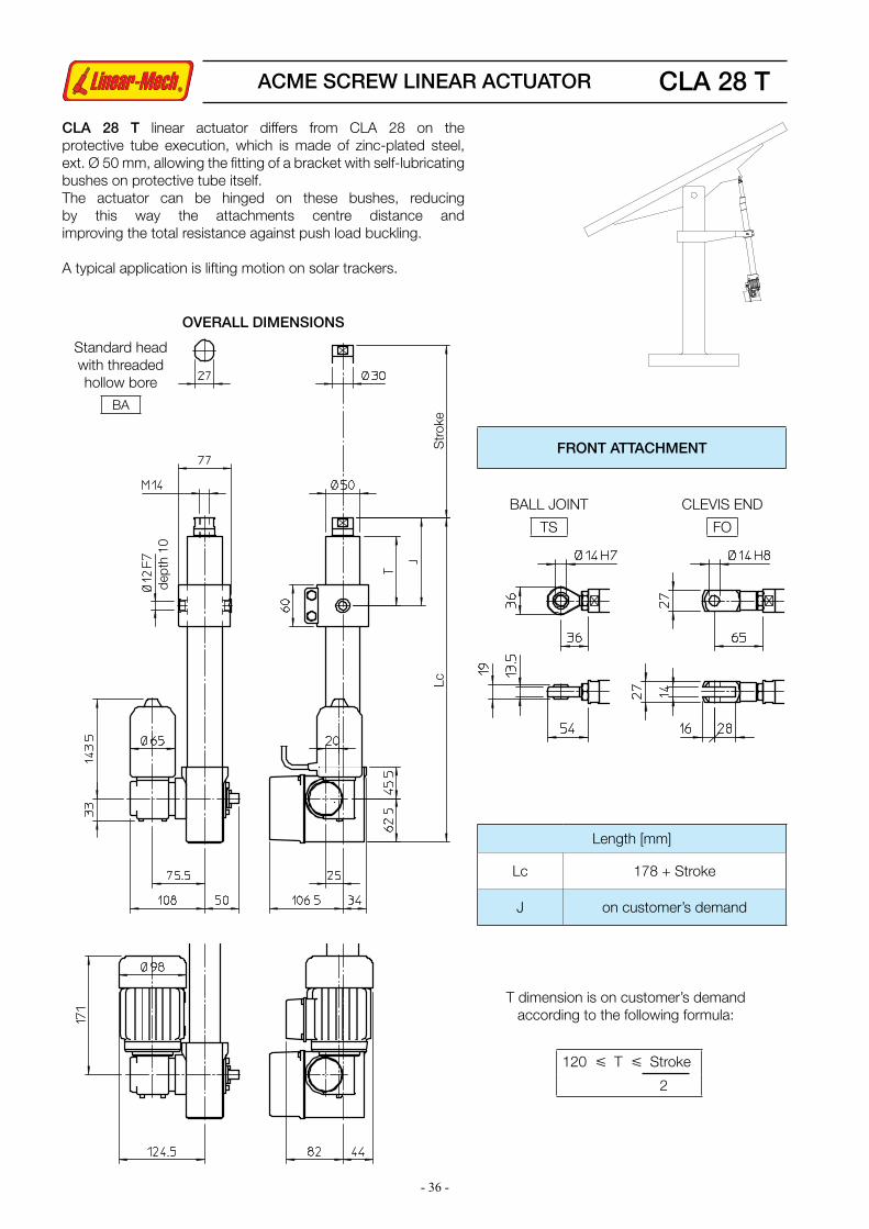
CLA 28 T
CLA 28 T linear actuator differs from CLA 28 on the protective tube execution, which is made of zinc-plated steel, ext. Ø 50 mm, allowing the fitting of a bracket with self-lubricating bushes on protective tube itself.The actuator can be hinged on these bushes, reducing by this way the attachments centre distance and improving the total resistance against push load buckling.
A typical application is lifting motion on solar trackers.
OVERALL DIMENSIONS
FRONT ATTACHMENT
Length [mm]
Lc 178 + Stroke
J on customer’s demand
T dimension is on customer’s demand according to the following formula:
Str
oke
Lc
dept
h 10
120 £ T £ Stroke
2
ACME SCREW LINEAR ACTUATOR
Standard head with threaded hollow bore
BA
BALL JOINT
TS
CLEVIS END
FO

- 37 -
CLA 28 T
PERFORMANCES AND FEATURES§ Pull-Push load up to 10 000 N§Linear speed up to 8 mm/s (DC motor)§Linear speed up to 3,7 mm/s (AC motor)§Standard stroke lengths: 400, 500, 600, 700, 800, 900, 1 000 mm (for different / longer stroke lengths please contact us)§Cast iron housing with integral rear attachment §Zinc-plated steel hinge on outer tube with self-lubricating bushes§Zinc-plated steel outer tube with increased thickness§Chrome-plated steel push rod – tolerance f7§Stainless steel AISI 303 front attachment §Motors: - 12, 24 or 36 V DC motor with electromagnetic noise suppressor - AC 3-phase or 1-phase motor (motor features details on pages 69, 70)§Duty cycle with max load: DC motor max 15% over 10 min at (-10 ... +40) °C AC motor max 30% over 10 min at (-10 ... +40) °C§Standard protection: with DC motor IP65 - Test IP6X according to EN 60529 §12 §13.4-13.6 - Test IPX5 according to EN 60529 §14.2.5 (tests made with not running actuator) with AC motor without brake IP55 with AC brake-motor IP54
§ Standard motor and first stage gearbox unit mounting position as per sketch (right-hand, code RH)§Long-life lubrication, maintenance free
ACCESSORIES§ Different front attachments§Stainless steel push rod (code SS)§Anti-turn device (code AR)§Adjustable electric stroke end switches (code FC2)§Adjustable electric stroke end switches, switching off the motor (code FC2X) (not available with AC 3-phase motor)§Extra switch for intermediate position (code FC)§Rotative potentiometer 5kOhm for positioning control (code POR5K)
NOTE: Extra limit switch and rotative potentiometer cannot be selected together
OPTIONS§ Motor and first stage gearbox unit mounting position on opposite side (left-hand, code LH)§Fixing attachment turned at 90° (code RPT 90)
2-starts acme screw Tr 18×8 (P4)0.06 kW - 2 pole motor
RATIO LOAD [N] SPEED [mm/s]
RL/RH2 3600 3.7RL/RV2 5500 2.4RL/RN2 9600 1.2
PERFORMANCES with 24 V DC motor 2-starts acme screw Tr 18×8 (P4)
Spe
ed [m
m/s
]
Load [kN] Load [kN]
Cur
rent
[A]
Self-locking conditionsInformation about statically self-locking conditions with pull or push load on page 68.
PERFORMANCES with AC 3-phase 50 Hz 230/400 V or 1-phase 50 Hz 230 V motor
ORDERING CODE EXAMPLE
CLA 28 T RL1 C800 CC 24 V FC2 POR 5K
ActuatorSelected
ratioRequired
strokeMotor
Stroke end switches
Accessories Options
ACME SCREW LINEAR ACTUATOR

- 38 -
LMI 02
PERFORMANCES AND FEATURES§ Pull-Push load up to 750 N§Linear speed up to 19 mm/s§Standard stroke lengths: 100, 150, 200, 250, 300 mm§Aluminium rear attachment §Anodized aluminium housing and protective tube §Anodized aluminium push rod §Stainless steel AISI 303 front attachment §12 or 24 V DC motor , standard protection IP54
MOTOR WIRING
OVERALL DIMENSIONS
STROKE CODE
STROKE [mm]
LENGTH MASS [kg]Lc [mm] La [mm] T
C100 100 345 445 329 1.05C150 150 395 545 379 1.30C200 200 445 645 429 1.55C250 250 495 745 479 1.80C300 300 545 845 529 2.05
§Duty cycle with max load: 15% over 10 min at (-10 ... +40) °C§Long-life lubrication, maintenance free
ACCESSORIES§Stainless steel push rod (code SS)§Two adjustable stroke end switches (code FCM)§Extra switches for intermediate position
La =Lc + Stroke
Stroke Lc
T
EXTENDING
BROWN M =BLUE
RETRACTING
Stroke end reed switches FCM
Load [N] Load [N]
Spe
ed [m
m/s
]
Cur
rent
[A]
PERFORMANCES with 24 V DC motor(Performances with 12 V DC motor: same load, linear speed 10 % less, electrical consumption 2 times more)
ORDERING CODE EXAMPLE
LMI 02 RL1 C200 CC 24 V FCM
ActuatorSelected
ratioRequired
strokeMotor
Stroke end switches
Accessories
Motor cable length 0.3 m
ACME SCREW LINEAR ACTUATOR
Self-locking conditionsInformation about statically self-locking conditions with pull or push load on page 68.
- 39 -
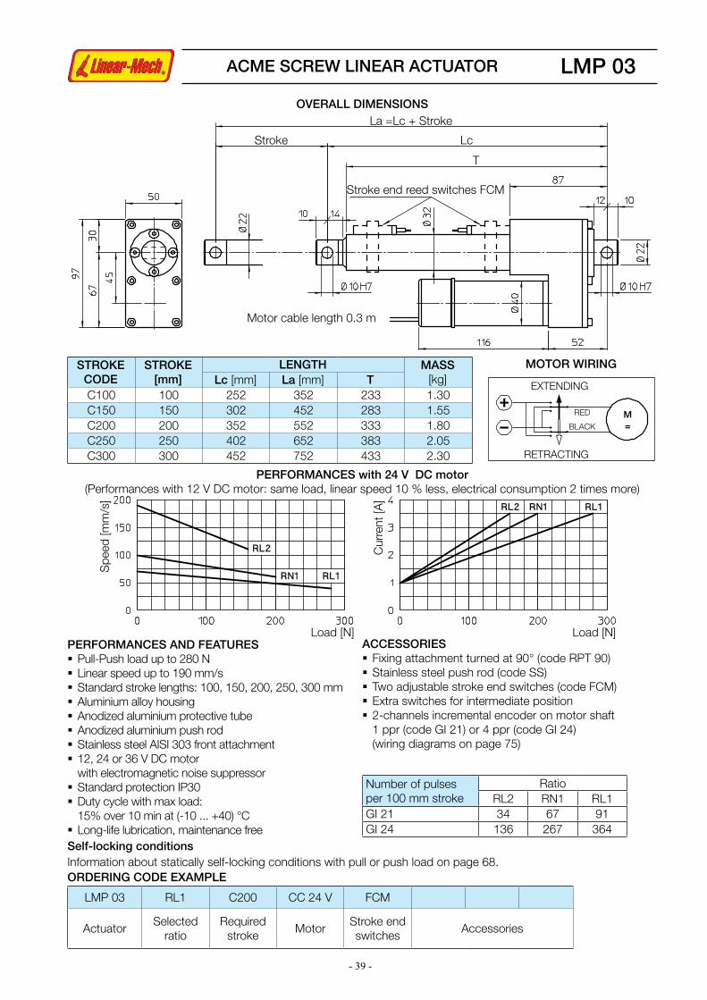
LMP 03
Number of pulses per 100 mm stroke
RatioRL2 RN1 RL1
GI 21 34 67 91GI 24 136 267 364
ACCESSORIES§ Fixing attachment turned at 90° (code RPT 90)§Stainless steel push rod (code SS)§Two adjustable stroke end switches (code FCM)§Extra switches for intermediate position§2-channels incremental encoder on motor shaft 1 ppr (code GI 21) or 4 ppr (code GI 24) (wiring diagrams on page 75)
PERFORMANCES AND FEATURES§ Pull-Push load up to 280 N§Linear speed up to 190 mm/s§Standard stroke lengths: 100, 150, 200, 250, 300 mm§Aluminium alloy housing§Anodized aluminium protective tube §Anodized aluminium push rod §Stainless steel AISI 303 front attachment §12, 24 or 36 V DC motor with electromagnetic noise suppressor§Standard protection IP30§Duty cycle with max load: 15% over 10 min at (-10 ... +40) °C§Long-life lubrication, maintenance free
STROKE CODE
STROKE [mm]
LENGTH MASS [kg]Lc [mm] La [mm] T
C100 100 252 352 233 1.30C150 150 302 452 283 1.55C200 200 352 552 333 1.80C250 250 402 652 383 2.05C300 300 452 752 433 2.30
La =Lc + Stroke
Stroke Lc
T
Motor cable length 0.3 m
MOTOR WIRING
EXTENDING
RED M =BLACK
RETRACTING
Load [N] Load [N]
Spe
ed [m
m/s
]
Cur
rent
[A]
PERFORMANCES with 24 V DC motor(Performances with 12 V DC motor: same load, linear speed 10 % less, electrical consumption 2 times more)
Stroke end reed switches FCM
ORDERING CODE EXAMPLE
LMP 03 RL1 C200 CC 24 V FCM
ActuatorSelected
ratioRequired
strokeMotor
Stroke end switches
Accessories
Self-locking conditionsInformation about statically self-locking conditions with pull or push load on page 68.
ACME SCREW LINEAR ACTUATOR
OVERALL DIMENSIONS
- 40 -
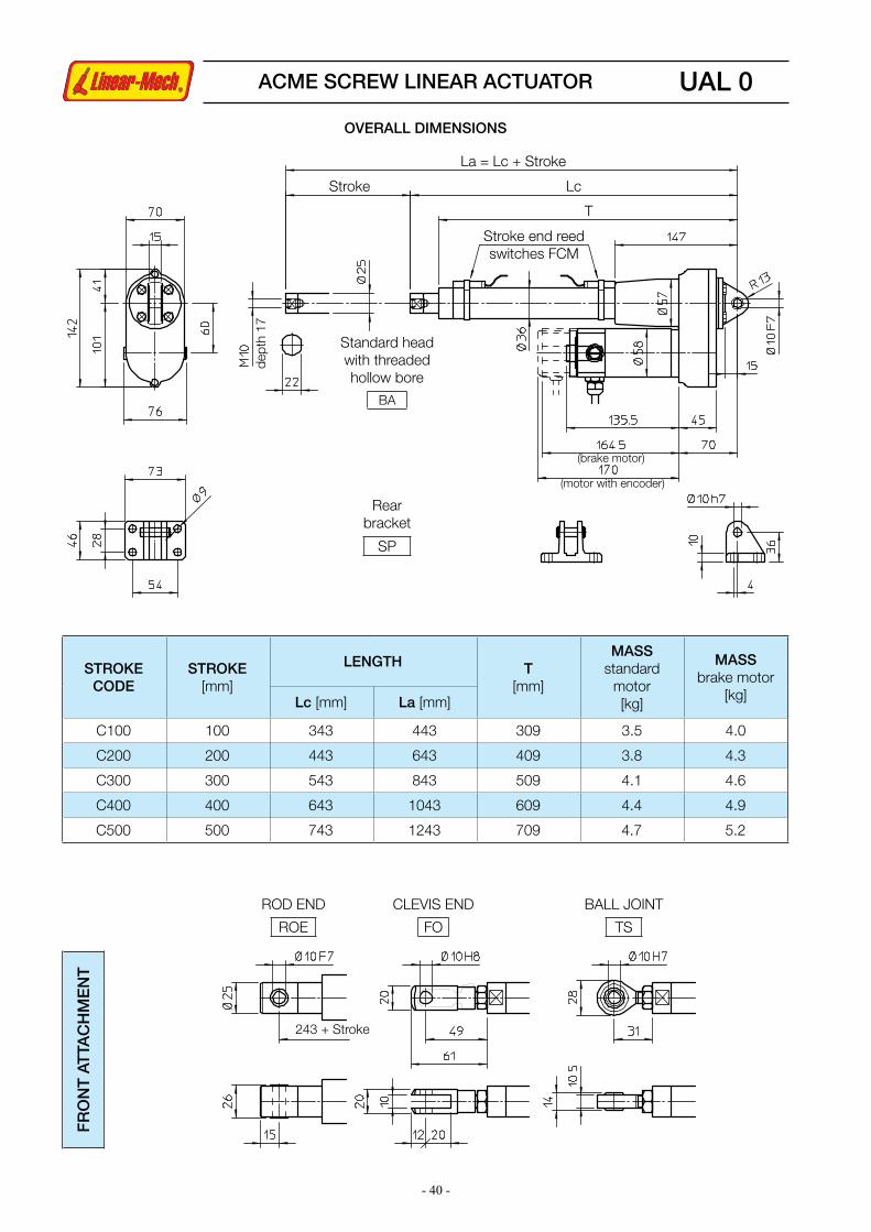
UAL 0F
RO
NT
AT
TAC
HM
EN
T
243 + Stroke
STROKE CODE
STROKE[mm]
LENGTH T [mm]
MASS standard
motor[kg]
MASS brake motor
[kg]Lc [mm] La [mm]
C100 100 343 443 309 3.5 4.0
C200 200 443 643 409 3.8 4.3
C300 300 543 843 509 4.1 4.6
C400 400 643 1043 609 4.4 4.9
C500 500 743 1243 709 4.7 5.2
T
Stroke end reed switches FCM
LcStroke
La = Lc + Stroke
(brake motor)
(motor with encoder)
dept
h 17
Rear bracket
SP
ACME SCREW LINEAR ACTUATOR
OVERALL DIMENSIONS
Standard head with threaded hollow bore
BA
BALL JOINT
TS
CLEVIS END
FO
ROD END
ROE

- 41 -
UAL 0
PERFORMANCES AND FEATURES§ Pull-Push load up to 400 N§Linear speed up to 600 mm/s§Standard stroke lengths: 100, 200, 300, 400, 500 mm (for different / longer stroke lengths please contact us)§Aluminium alloy housing and rear attachment with bronze bush §Anodized aluminium outer tube§Chrome-plated push rod – tolerance f7§Standard head BA or rod end ROE in stainless steel AISI 303 with bronze bush§12 or 24 V DC motor (motor features details on page 69)§Duty cycle with max load: 30% over 10 min at (-10 ... +40) °C§Standard protection IP 54§Long-life lubrication, maintenance free
1-start acme screw Tr 14×4
RATIO LOAD [N] SPEED [mm/s] CURRENT [A]
RV1 210 200 4RN1 390 100 4
2-starts acme screw Tr 14×8 (P4)
RATIO LOAD [N] SPEED [mm/s] CURRENT [A]
RV2 120 400 4RN2 230 200 4
3-starts acme screw Tr 14×12 (P4)
RATIO LOAD [N] SPEED [mm/s] CURRENT [A]
RV3 90 600 4RN3 170 300 4
ACCESSORIES§ Different front attachments§Stainless steel push rod (code SS)§Rear bracket (code SP)§Brake motor§Two adjustable stroke end reed switches (code FCM)§Extra switch for intermediate position §Bi-directional incremental encoder, 100 ppr with zero set pulse, Push-Pull, 8÷24 Vcc (code EH38) (encoder features details on page 75)
OPTIONS§Fixing attachment turned at 90° (code RPT 90)
PERFORMANCES with 24 V DC motor(Performances with 12 V DC motor: same load, linear speed 10 % less, electrical consumption 2 times more)
Self-locking conditionsInformation about statically self-locking conditions with pull or push load on page 68.
ORDERING CODE EXAMPLE
UAL 0 RL1 C200 CC 24 V FCM
ActuatorSelected
ratioRequired
strokeMotor
Stroke end switches
Accessories Options
ACME SCREW LINEAR ACTUATOR

- 42 -
BSA 08BALL SCREW LINEAR ACTUATOR
OVERALL DIMENSIONS
Lc
T
La =Lc + Stroke
Stroke
Motor cable length 0.3 m
Pin
Rear bracket
SP
STROKE CODE
STROKE[mm]
LENGTH T [mm]
MASS [Kg]Lc [mm] La [mm]
C100 100 327 427 296 3.6
C150 150 377 527 346 3.7
C200 200 427 627 396 3.9
C250 250 477 727 446 4.0
C300 300 527 827 496 4.2
C400 400 627 1027 596 4.5
C500 500 727 1227 696 4.8
Stroke end reed switches FCM

- 43 -
BSA 08
PERFORMANCES AND FEATURES§Pull-Push load up to 5 000 N§Linear speed up to 64 mm/s§Standard stroke lengths: 100, 150, 200, 250, 300, 400, 500 mm §Ball screw BS 14 x 5 (technical details on page 66) §Aluminium alloy housing and rear attachment with bronze bush§Anodized aluminium outer tube§Chrome-plated steel push rod – tolerance f7§Stainless steel AISI 303 front attachment with bronze bush §12, 24 or 36 V DC motor with electromagnetic noise suppressor (motor features details on page 69) (BRAKE NOT AVAILABLE)§Duty cycle with max load: 50% over 10 min at (-10 ... +40) °C§Standard motor mounting position as per sketch (right-hand, code RH)
Spe
ed [m
m/s
]
Load [N] Load [N]
Cur
rent
[A]
PERFORMANCES with 24 V DC motor(Performances with 12 V DC motor: same load, linear speed 10 % less, electrical consumption 2 times more)
§Standard protection IP 65 - Test IP6X according to EN 60529 §12 §13.4-13.6 - Test IPX5 according to EN 60529 §14.2.5 (tests made with not running actuator)§Long-life lubrication, maintenance free
ACCESSORIES§Stainless steel push rod (code SS)§Rear bracket (code SP) §Mechanical overload protection: safety clutch (code FS)§Two adjustable stroke end reed switches (code FCM)§Extra switch for intermediate position
OPTIONS§Motor mounting position on opposite side (left-hand, code LH)§Fixing attachment turned at 90° (code RPT 90)
Self-locking conditionsBrake motor not available. Therefore the statically self-locking condition is not achievable.Information about statically self-locking conditions with pull or push load on page 68.
ORDERING CODE EXAMPLE
BSA 08 RL2 C200 CC 24 V FCM
ActuatorSelected
ratioRequired
strokeMotor
Stroke end switches
Accessories Options
BALL SCREW LINEAR ACTUATOR

- 44 -
BALL SCREW LINEAR ACTUATOR BSA 10 AC motor
OVERALL DIMENSIONS
Lc
T
La =Lc + Stroke
Strokede
pth
17
(bra
ke m
otor
)
Pin
Capacitor
Rear bracket
SP
159 + Stroke
Stroke end electric switches FCE
89 + Stroke
Stroke end reed switches FCM
FCE cable length 1.5 m
Self-locking conditionsSelf-locking condition is achievable with brake motor only.Information about statically self-locking conditions with pull or push load on page 68.
STROKE CODE
Actuator - FCE switches Actuator - FCM switchesT
[mm]
MASS [Kg]STROKE
[mm]LENGTH STROKE
[mm]LENGTH standard
motorbrake motorLc [mm] La [mm] Lc [mm] La [mm]
C100 85 281 366 53 313 366 239 4.8 5.3
C150 135 331 466 103 363 466 289 4.9 5.4
C200 185 381 566 153 413 566 339 5.1 5.6
C250 235 431 666 203 463 666 389 5.2 5.7
C300 285 481 766 253 513 766 439 5.4 5.9
C400 385 581 966 353 613 966 539 5.7 6.2
C500 485 681 1166 453 713 1166 639 6.0 6.5
Standard head with threaded hollow bore
BA
80

- 45 -
BALL SCREW LINEAR ACTUATOR BSA 10 AC motorF
RO
NT
AT
TAC
HM
EN
T
196 + Strokewith FCE 211 + Stroke
with FCM 260 + Stroke
Ball screw BS 14 x 5
RATIO
0.09 kW - 4 pole motor 0.12 kW - 2 pole motor
LOAD[N]
SPEED[mm/s]
LOAD[N]
SPEED[mm/s]
RH1 2180 29 1490 58
RV1 3290 19 2300 37
RN1 5000 9 4230 19
RL1 5000 4.5 5000 9
RXL1 5000 2.5 5000 4.5
PERFORMANCES with AC 3-phase 50 Hz 230/400 V or 1-phase 50 Hz 230 V motor
PERFORMANCES AND FEATURES§ Push load up to 5 000 N§Pull load up to 4 000 N§Linear speed up to 58 mm/s§Standard stroke lengths: 100, 150, 200, 250, 300, 400, 500 mm (for different / longer stroke lengths please contact us)§Ball screw BS 14 x 5 (technical details on page 66) §Aluminium alloy housing and rear attachment with bronze bush§Anodized aluminium outer tube§Chrome-plated steel push rod – tolerance f7§Standard head BA or rod end ROE in stainless steel AISI 303 with bronze bush§3-phase or 1-phase motor (motor features details on page 70)§Duty cycle with max load: 100% over 10 min at (-10 ... +40) °C§Standard protection IP 55 (IP 54 with brake)§Standard motor mounting position as per sketch (right-hand, code RH)§Long-life lubrication, maintenance free
ACCESSORIES§ Different front attachments§Stainless steel push rod (code SS)§Rear bracket (code SP) §Mechanical overload protection: safety clutch (code FS)§Brake motor §Two adjustable stroke end reed switches (code FCM)§Extra switch for intermediate position §Electro-mechanical stroke end switch (code FCE) (for linear speed up to 30 mm/s) (technical data on page 72)
OPTIONS§Motor mounting position on opposite side (left-hand, code LH)§Fixing attachment turned at 90° (code RPT 90)
ORDERING CODE EXAMPLE
BSA 10 RL1 C200 CA 230/400 V FCM
ActuatorSelected
ratioRequired
strokeMotor
Stroke end switches
Accessories Options
BALL JOINT
TS
CLEVIS END
FO
ROD END
ROE

- 46 -
BALL SCREW LINEAR ACTUATOR BSA 10 DC motor
OVERALL DIMENSIONS
Lc
T
La =Lc + Stroke
Stroke
Pin
(bra
ke m
otor
)
(mot
or w
ith e
ncod
er)
Rear bracket
SP
dept
h 1
7
159 + Stroke
89 + Stroke
Stroke end reed switches FCM
Stroke end electric switches FCE
Self-locking conditionsSelf-locking condition is achievable with brake motor only.Information about statically self-locking conditions with pull or push load on page 68.
STROKE CODE
Actuator - FCE switches Actuator - FCM switchesT
[mm]
MASS [Kg]STROKE
[mm]LENGTH STROKE
[mm]LENGTH standard
motorbrake motorLc [mm] La [mm] Lc [mm] La [mm]
C100 85 281 366 53 313 366 239 4.8 5.3
C150 135 331 466 103 363 466 289 4.9 5.4
C200 185 381 566 153 413 566 339 5.1 5.6
C250 235 431 666 203 463 666 389 5.2 5.7
C300 285 481 766 253 513 766 439 5.4 5.9
C400 385 581 966 353 613 966 539 5.7 6.2
C500 485 681 1166 453 713 1166 639 6.0 6.5
Standard head with threaded hollow bore
BA
FCE cable length 1.5 m

- 47 -
BALL SCREW LINEAR ACTUATOR BSA 10 DC motor
PERFORMANCES AND FEATURES§ Push load up to 5 000 N§Pull load up to 4 000 N§Linear speed up to 63 mm/s§Standard stroke lengths: 100, 150, 200, 250, 300, 400, 500 mm (for different / longer stroke lengths please contact us)§Ball screw BS 14 x 5 (technical details on page 66) §Aluminium alloy housing and rear attachment with bronze bush§Anodized aluminium outer tube§Chrome-plated steel push rod – tolerance f7§Standard head BA or rod end ROE in stainless steel AISI 303 with bronze bush§12 or 24 V DC motor (motor features details on page 69)§Duty cycle with max load: 100% over 10 min at (-10 ... +40) oC§Standard protection IP 54§Standard motor mounting position as per sketch (right-hand, code RH)§Long-life lubrication, maintenance free
ACCESSORIES§ Different front attachments§Stainless steel push rod (code SS)§Rear bracket (code SP) §Mechanical overload protection: safety clutch (code FS)§Brake motor §Two adjustable stroke end reed switches (code FCM)§Extra switch for intermediate position §Electro-mechanical stroke end switch (code FCE) (for linear speed up to 30 mm/s) (technical data on page 72)§Bi-directional incremental encoder, 100 ppr with zero set pulse, Push-Pull, 8÷24 Vcc (code EH38) (encoder features details on page 75)
OPTIONS§Motor mounting position on opposite side (left-hand, code LH)§Fixing attachment turned at 90° (code RPT 90)
Ball screw BS 14 x 5
RATIOLOAD
[N]SPEED[mm/s]
CURRENT[A]
RH1 800 63 4
RV1 1260 40 4
RN1 2350 20 4
RL1 4130 10 4
RXL1 5000 5 3
PERFORMANCES with 24 V DC motor(Performances with 12 V DC motor: same load, linear speed 10 % less, electrical consumption 2 times more)
ORDERING CODE EXAMPLE
BSA 10 RL1 C200 CC 24 V FCM
ActuatorSelected
ratioRequired
strokeMotor
Stroke end switches
Accessories Options
FR
ON
T A
TTA
CH
ME
NT
196 + Stroke
with FCE 211 + Stroke
with FCM 260 + Stroke
BALL JOINT
TS
CLEVIS END
FO
ROD END
ROE

- 48 -
80
OVERALL DIMENSIONS
Lc
T
La =Lc + Stroke
Strokede
pth1
7
Pin
Capacitor
Rear bracket
SP
Stroke end reed switches FCM
BALL SCREW LINEAR ACTUATOR BSA 11 AC motor
STROKECODE
STROKE[mm]
LENGTH T [mm]
MASS [Kg]Lc [mm] La [mm]
C100 100 343 443 312 5.4
C150 150 393 543 362 5.5
C200 200 443 643 412 5.7
C250 250 493 743 462 5.8
C300 300 543 843 512 6.0
C400 400 643 1043 612 6.3
C500 500 743 1243 712 6.6
Length [mm]
Lc 243 + Stroke
T 212 + Stroke
Self-locking conditionsSelf-locking condition is achievable with brake motor only.Information about statically self-locking conditions with pull or push load on page 68.
(bra
ke m
otor
)
Standard head with threaded hollow bore
BA
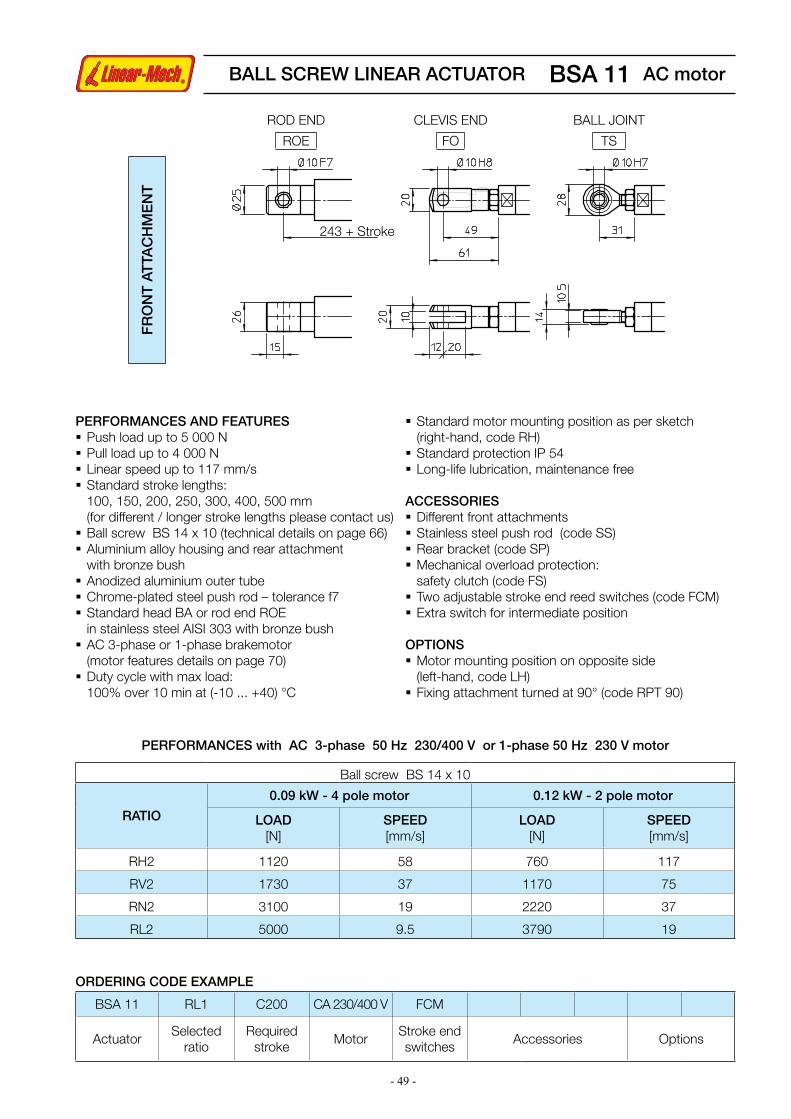
- 49 -
FR
ON
T A
TTA
CH
ME
NT
243 + Stroke
BALL SCREW LINEAR ACTUATOR BSA 11 AC motor
PERFORMANCES with AC 3-phase 50 Hz 230/400 V or 1-phase 50 Hz 230 V motor
PERFORMANCES AND FEATURES§ Push load up to 5 000 N§Pull load up to 4 000 N§Linear speed up to 117 mm/s§Standard stroke lengths: 100, 150, 200, 250, 300, 400, 500 mm (for different / longer stroke lengths please contact us)§Ball screw BS 14 x 10 (technical details on page 66) §Aluminium alloy housing and rear attachment with bronze bush§Anodized aluminium outer tube§Chrome-plated steel push rod – tolerance f7§Standard head BA or rod end ROE in stainless steel AISI 303 with bronze bush§AC 3-phase or 1-phase brakemotor (motor features details on page 70)§Duty cycle with max load: 100% over 10 min at (-10 ... +40) °C
§Standard motor mounting position as per sketch (right-hand, code RH)§Standard protection IP 54§Long-life lubrication, maintenance free
ACCESSORIES§ Different front attachments§Stainless steel push rod (code SS)§Rear bracket (code SP) §Mechanical overload protection: safety clutch (code FS)§Two adjustable stroke end reed switches (code FCM)§Extra switch for intermediate position
OPTIONS§Motor mounting position on opposite side (left-hand, code LH)§Fixing attachment turned at 90° (code RPT 90)
ORDERING CODE EXAMPLE
BSA 11 RL1 C200 CA 230/400 V FCM
ActuatorSelected
ratioRequired
strokeMotor
Stroke end switches
Accessories Options
Ball screw BS 14 x 10
RATIO
0.09 kW - 4 pole motor 0.12 kW - 2 pole motor
LOAD[N]
SPEED[mm/s]
LOAD[N]
SPEED[mm/s]
RH2 1120 58 760 117
RV2 1730 37 1170 75
RN2 3100 19 2220 37
RL2 5000 9.5 3790 19
BALL JOINT
TS
CLEVIS END
FO
ROD END
ROE

- 50 -
OVERALL DIMENSIONS
BALL SCREW LINEAR ACTUATOR BSA 11 DC motor
Lc
T
La =Lc + Stroke
Stroke
Pin
Rear bracket
SP
dept
h 17
Stroke end reed switches FCM
STROKECODE
STROKE[mm]
LENGTH T [mm]
MASS [Kg]Lc [mm] La [mm]
C100 100 343 443 312 4.1
C150 150 393 543 362 4.2
C200 200 443 643 412 4.4
C250 250 493 743 462 4.5
C300 300 543 843 512 4.7
C400 400 643 1043 612 5.0
C500 500 743 1243 712 5.3
Length [mm]
Lc 243 + Stroke
T 212 + Stroke
(bra
ke m
otor
)
Standard head with threaded hollow bore
BA
Self-locking conditionsSelf-locking condition is achievable with brake motor only.Information about statically self-locking conditions with pull or push load on page 68.

- 51 -
BALL SCREW LINEAR ACTUATOR BSA 11 DC motor
PERFORMANCES AND FEATURES§ Push-Pull load up to 5 000 N§Linear speed up to 125 mm/s§Standard stroke lengths: 100, 150, 200, 250, 300, 400, 500 mm (for different / longer stroke lengths please contact us)§Ball screw BS 14 x 10 (technical details on page 66) §Aluminium alloy housing and rear attachment with bronze bush§Anodized aluminium outer tube§Chrome-plated steel push rod – tolerance f7§Standard head BA or rod end ROE in stainless steel AISI 303 with bronze bush§12 or 24 V DC brakemotor (motor features details on page 69)§Duty cycle with max load: 100% over 10 min at (-10 ... +40) °C
§Standard motor mounting position as per sketch (right-hand, code RH)§Standard protection IP 54§Long-life lubrication, maintenance free
ACCESSORIES§ Different front attachments§Stainless steel push rod (code SS)§Rear bracket (code SP) §Mechanical overload protection: safety clutch (code FS)§Two adjustable stroke end reed switches (code FCM)§Extra switch for intermediate position
OPTIONS§Motor mounting position on opposite side (left-hand, code LH)§Fixing attachment turned at 90° (code RPT 90)
ORDERING CODE EXAMPLE
BSA 11 RL1 C200 CC 24 V FCM
ActuatorSelected
ratioRequired
strokeMotor
Stroke end switches
Accessories Options
Ball screw BS 14 x 10
RATIOLOAD
[N]SPEED[mm/s]
CURRENT[A]
RH2 410 125 4
RV2 640 80 4
RN2 1200 40 4
RL2 2100 20 4
PERFORMANCES with 24 V DC motor(Performances with 12 V DC motor: same load, linear speed 10 % less, electrical consumption 2 times more)
FR
ON
T A
TTA
CH
ME
NT
243 + Stroke
BALL JOINT
TS
CLEVIS END
FO
ROD END
ROE

- 52 -
BSA 12BALL SCREW LINEAR ACTUATOR
OVERALL DIMENSIONS
Lc
T
La =Lc + Stroke
Stroke
PinCapacitor
Length Actuator
Lc [mm] 279 + Stroke
T [mm] 238 + Stroke
dept
h 17
Rear bracket
SP
(bra
ke m
otor
)
Stroke end reed switches FCM
STROKECODE
STROKE[mm]
LENGTH T [mm]
MASS [Kg]Lc [mm] La [mm]
C100 100 379 479 338 8.9
C200 200 479 679 438 9.7
C300 300 579 879 538 10.5
C400 400 679 1079 638 11.3
C500 500 779 1279 738 12.1
C600 600 879 1479 838 12.9
C700 700 979 1679 938 13.7
C800 800 1079 1879 1038 14.5
Standard head with threaded hollow bore
BA
Self-locking conditionsSelf-locking condition is achievable with brake motor only.Information about statically self-locking conditions with pull or push load on page 68.

- 53 -
BSA 12F
RO
NT
AT
TAC
HM
EN
T
Ball screw BS 20 x 5
RATIO0.18 kW - 4 pole motor 0.25 kW - 2 pole motor
LOAD[N]
SPEED[mm/s]
LOAD[N]
SPEED[mm/s]
RV1 4300 29 3060 58
RN1 9000 7 9000 14
RL1 9000 3.5 9000 7
ACCESSORIES§ Different front attachments§Stainless steel push rod (code SS)§Rear bracket (code SP) §Mechanical overload protection: safety clutch (code FS)§Two adjustable stroke end reed switches (code FCM)§Extra switch for intermediate position
OPTIONS§Motor mounting position on opposite side (left-hand, code LH)§Fixing attachment turned at 90° (code RPT 90)
PERFORMANCES AND FEATURES§ Push-Pull load up to 9 000 N§Linear speed up to 58 mm/s§Standard stroke lengths: 100, 200, 300, 400, 500, 600, 700, 800 mm§Ball screw BS 20 x 5 (technical details on page 66) §Aluminium alloy housing and rear attachment with bronze bush§Anodized aluminium outer tube§Chrome-plated steel push rod – tolerance f7§Standard head BA or rod end ROE in stainless steel AISI 303 with bronze bush§AC 3-phase or 1-phase brakemotor (motor features details on page 70)§Duty cycle with max load: 100% over 10 min at (-10 ... +40) °C§Standard motor mounting position as per sketch (right-hand, code RH)§Standard protection IP 54§Long-life lubrication, maintenance free
ORDERING CODE EXAMPLE
BSA 12 RL1 C200 CA 230/400 V FCM
ActuatorSelected
ratioRequired
strokeMotor
Stroke end switches
Accessories Options
299 + Stroke
PERFORMANCES with AC 3-phase 50 Hz 230/400 V or 1-phase 50 Hz 230 V motor
BALL SCREW LINEAR ACTUATOR
BALL JOINT
TS
CLEVIS END
FO
ROD END
ROE

- 54 -
1
2
OVERALL DIMENSIONS
Lc Lc
T T
La =Lc + Stroke La = Lc + Stroke
Stroke
Pin
Capacitor
FR
ON
T A
TTA
CH
ME
NT
Rear bracket
SP
Attachment A1 Attachment A2
BALL SCREW LINEAR ACTUATOR CLB 25 AC motor
STROKE CODE
Actuator - Attachment A1 Actuator - Attachment A2 MASS [Kg]STROKE
[mm]LENGTH T
[mm]STROKE
[mm]LENGTH T
[mm]standard
motorbrake motorLc [mm] La [mm] Lc [mm] La [mm]
C100 100 348 448 317 100 355 455 324 5.2 5.7
C150 150 398 548 367 150 405 555 374 5.3 5.8
C200 200 448 648 417 200 455 655 424 5.5 6.0
C250 250 498 748 467 250 505 755 474 5.6 6.1
C300 300 548 848 517 300 555 855 524 5.8 6.3
C400 400 648 1048 617 400 655 1055 624 6.1 6.6
dept
h 17
(bra
ke m
otor
)
Lc = Q + Stroke
1. STROKE END SWITCHES BOX AND POTENTIOMETER2. MOTOR SHAFT EXTENSION for: Emergency manual activation Stroke end switches and potentiometer adjustment
Standard head with threaded hollow bore
BA
Q[mm]
Attachment A1 Attachment A2253 260
BALL JOINT
TS
CLEVIS END
FO
ROD END
ROE

- 55 -
Ball screw BS 14 x 5
RATIO0.09 kW - 4 pole motor 0.12 kW - 2 pole motor
LOAD [N] SPEED [mm/s] LOAD [N] SPEED [mm/s]
RH1 2170 29 1490 58
RV1 3270 19 2300 37
RN1 5000 9.5 4230 19
RL1 5000 4.5 5000 9.5
RXL1 5000 2.5 5000 4.5
Ball screw BS 14 x 10
RATIO0.09 kW - 4 pole motor 0.12 kW - 2 pole motor
LOAD [N] SPEED [mm/s] LOAD [N] SPEED [mm/s]
RH2 1120 58 760 117
RV2 1730 37 1170 75
RN2 3100 19 2220 37
RL2 5000 9.5 3790 19
PERFORMANCES with AC 3-phase 50 Hz 230/400 V or 1-phase 50 Hz 230 V motor
PERFORMANCES AND FEATURES§ Push load up to 5 000 N§Pull load up to 4 000 N§Linear speed up to 117 mm/s§Standard stroke lengths: 100, 150, 200, 250, 300, 400 mm §Ball screw BS 14 x 5 or BS 14 x 10 (technical details on page 66) §Aluminium alloy housing §Anodized aluminium outer tube§Chrome-plated steel push rod – tolerance f7§Rear attachment: - A1: zinc-plated steel rod end with bronze bush - A2: aluminium alloy with bronze bush §Standard head BA or rod end ROE in stainless steel AISI 303 with bronze bush§AC 3-phase or 1-phase motor (motor features details on page 70)§Duty cycle with max load: 100% over 10 min at (-10 ... +40) °C§Standard protection IP 55 (IP 54 with brake)§Standard motor mounting position as per sketch (right-hand, code RH)§Long-life lubrication, maintenance free
ACCESSORIES§ Different front attachments§Stainless steel push rod (code SS) §Rear bracket (code SP) with rear attachment A2§Mechanical overload protection: safety clutch (code FS)§Brakemotor§Adjustable electric stroke end switches (code FC2)§Adjustable electric stroke end switches, switching off the motor (code FC2X) (not available with AC 3-phase motor)§Extra switch for intermediate position (code FC)§Rotative potentiometer 5kOhm for positioning control (code POR5K)
NOTE: Extra limit switch and rotative potentiometer cannot be selected together
OPTIONS§Motor mounting position on opposite side (left-hand, code LH)§Fixing attachment turned at 90° (code RPT 90)
BALL SCREW LINEAR ACTUATOR CLB 25 AC motor
ORDERING CODE EXAMPLE
CLB 25 RL1 C200 CA 230/400 V FC2 POR 5K
ActuatorSelected
ratioRequired
strokeMotor
Stroke end switches
Accessories Options
Self-locking conditionsSelf-locking condition is achievable with brake motor only.Information about statically self-locking conditions with pull or push load on page 68.

- 56 -
1
2
BALL SCREW LINEAR ACTUATOR CLB 25 DC motor
OVERALL DIMENSIONS
Lc LcT T
La =Lc + Stroke La = Lc + StrokeStroke
Pin
dept
h 17
Motor cable length 0.3 m
Rear bracket
SP
Attachment A1 Attachment A2
FR
ON
T A
TTA
CH
ME
NT
STROKE CODE
Actuator - Attachment A1 Actuator - Attachment A2MASS
[Kg]STROKE[mm]
LENGTH T [mm]
STROKE[mm]
LENGTH T [mm]Lc [mm] La [mm] Lc [mm] La [mm]
C100 100 348 448 317 100 355 455 324 5.2
C150 150 398 548 367 150 405 555 374 5.3
C200 200 448 648 417 200 455 655 424 5.5
C250 250 498 748 467 250 505 755 474 5.6
C300 300 548 848 517 300 555 855 524 5.8
C400 400 648 1048 617 400 655 1055 624 6.1
(bra
ke m
otor
)
Lc = Q + Stroke
1. STROKE END SWITCHES BOX AND POTENTIOMETER2. MOTOR SHAFT EXTENSION for: Emergency manual activation Stroke end switches and potentiometer adjustment
Q[mm]
Attachment A1 Attachment A2253 260
Standard head with threaded hollow bore
BA
BALL JOINT
TS
CLEVIS END
FO
ROD END
ROE

- 57 -
PERFORMANCES AND FEATURES§ Push load up to 5 000 N§Pull load up to 4 000 N§Linear speed up to 125 mm/s§Standard stroke lengths: 100, 150, 200, 250, 300, 400 mm §Ball screw BS 14 x 5 or BS 14 x 10 (technical details on page 66) §Aluminium alloy housing §Anodized aluminium outer tube§Chrome-plated steel push rod – tolerance f7§Rear attachment: - A1: zinc-plated steel rod end with bronze bush - A2: aluminium alloy with bronze bush §Standard head BA or rod end ROE in stainless steel AISI 303 with bronze bush§12 or 24 V DC brakemotor (motor features details on page 69)§Duty cycle with max load: 100% over 10 min at (-10 ... +40) °C§Standard protection IP 54§Standard motor mounting position as per sketch (right-hand, code RH)§Long-life lubrication, maintenance free
ACCESSORIES§ Different front attachments§Stainless steel push rod (code SS) §Rear bracket (code SP) with rear attachment A2§Mechanical overload protection: safety clutch (code FS)§Adjustable electric stroke end switches (code FC2)§Adjustable electric stroke end switches, switching off the motor (code FC2X)§Extra switch for intermediate position (code FC)§Rotative potentiometer 5kOhm for positioning control (code POR5K)
NOTE: Extra limit switch and rotative potentiometer cannot be selected together
OPTIONS§Motor mounting position on opposite side (left-hand, code LH)§Fixing attachment turned at 90° (code RPT 90)
BALL SCREW LINEAR ACTUATOR CLB 25 DC motor
Ball screw BS 14 x 5
RATIOLOAD
[N]SPEED[mm/s]
CURRENT[A]
RH1 800 63 4
RV1 1260 40 4
RN1 2350 20 4
RL1 4130 10 4
RXL1 5000 5 3
Ball screw BS 14 x 10
RATIOLOAD
[N]SPEED[mm/s]
CURRENT[A]
RH2 410 125 4
RV2 640 80 4
RN2 1200 40 4
RL2 2100 20 4
PERFORMANCES with 24 V DC motor(Performances with 12 V DC motor: same load, linear speed 10 % less, electrical consumption 2 times more)
ORDERING CODE EXAMPLE
CLB 25 RL1 C200 CC 24 V FC2 POR 5K
ActuatorSelected
ratioRequired
strokeMotor
Stroke end switches
Accessories Options
Self-locking conditionsSelf-locking condition is achievable with brake motor only.Information about statically self-locking conditions with pull or push load on page 68.

- 58 -
CLB 2727
Ø30
M12
FR
ON
T A
TTA
CH
ME
NT
BALL SCREW LINEAR ACTUATOR
1
2
OVERALL DIMENSIONS
Lc Lc
T T
La =Lc + Stroke La = Lc + Stroke
Stroke
Pin
Capacitor
(bra
ke m
otor
)
Rear bracket
SP
Attachment A1 Attachment A2
STROKE CODE
Actuator - Attachment A1 Actuator - Attachment A2 MASS [Kg]STROKE
[mm]LENGTH T
[mm]STROKE
[mm]LENGTH T
[mm]standard
motorbrake motorLc [mm] La [mm] Lc [mm] La [mm]
C100 100 336 436 300 100 343 443 307 5.3 5.8
C150 150 386 536 350 150 393 543 357 5.5 6.0
C200 200 436 636 400 200 443 643 407 5.7 6.2
C300 300 536 836 500 300 543 843 507 6.1 6.6
C400 400 636 1036 600 400 643 1043 607 6.5 7.0
C500 500 736 1236 700 500 743 1243 707 6.9 7.4
dept
h 17
= Q + Stroke
Standard head with threaded hollow bore
BA
1. STROKE END SWITCHES BOX AND POTENTIOMETER2. MOTOR SHAFT EXTENSION for: Emergency manual activation Stroke end switches and potentiometer adjustment
Q[mm]
Attachment A1 Attachment A2239 246
BALL JOINT
TS
CLEVIS END
FO
ROD END
ROE

- 59 -
CLB 27
Ball screw BS 16 x 5
RATIO0.09 kW - 4 pole motor 0.12 kW - 2 pole motor
LOAD[N]
SPEED[mm/s]
LOAD[N]
SPEED[mm/s]
RH1 2160 29 1480 58RV1 3260 19 2300 37RN1 5990 9.5 4170 19RL1 7000 4.5 7000 9.5
PERFORMANCES AND FEATURES§ Push load up to 7 000 N§Pull load up to 4 000 N§Linear speed up to 58 mm/s§Standard stroke lengths: 100, 150, 200, 300, 400, 500 mm §Ball screw BS 16 x 5 (technical details on page 66) §Aluminium alloy housing §Anodized aluminium outer tube§Chrome-plated steel push rod§Rear attachment: - A1: zinc-plated steel rod end with bronze bush - A2: aluminium alloy with bronze bush §Standard head BA or rod end ROE in stainless steel AISI 303 with bronze bush§AC 3-phase or 1-phase motor (motor features details on page 70)§Duty cycle with max load: 100% over 10 min at (-10 ... +40) °C§Standard protection IP 55 (IP 54 with brake)§Standard motor mounting position as per sketch (right-hand, code RH)§Long-life lubrication, maintenance free
ACCESSORIES§ Different front attachments§Stainless steel push rod (code SS) §Rear bracket (code SP) with rear attachment A2§Mechanical overload protection: safety clutch (code FS)§Brakemotor§Adjustable electric stroke end switches (code FC2)§Adjustable electric stroke end switches, switching off the motor (code FC2X) (not available with AC 3-phase motor)§Extra switch for intermediate position (code FC)§Rotative potentiometer 5kOhm for positioning control (code POR5K)
NOTE: Extra limit switch and rotative potentiometer cannot be selected together
OPTIONS§Motor mounting position on opposite side (left-hand, code LH)§Fixing attachment turned at 90° (code RPT 90)
BALL SCREW LINEAR ACTUATOR
PERFORMANCES with AC 3-phase 50 Hz 230/400 V or 1-phase 50 Hz 230 V motor
ORDERING CODE EXAMPLE
CLB 27 RL1 C200 CA 400 V FC2 POR 5K
ActuatorSelected
ratioRequired
strokeMotor
Stroke end switches
Accessories Options
Self-locking conditionsSelf-locking condition is achievable with brake motor only.Information about statically self-locking conditions with pull or push load on page 68.

- 60 -
UBA 0F
RO
NT
AT
TAC
HM
EN
T
281+ Stroke
Length [mm] Actuator
Lc 281 + Stroke
T 249 + Stroke
OVERALL DIMENSIONS
T
LcStroke
La = Lc + Stroke
dept
h 17
Rear bracket
SP
BALL SCREW LINEAR ACTUATOR
Stroke end reed switches FCM
STROKE[mm]
LENGTH T [mm]
MASS [Kg]Lc [mm] La [mm] standard motor brake motor
100 381 481 349 3.7 4.2
200 481 681 449 4.0 4.5
300 581 881 549 4.3 4.8
400 681 1081 649 4.7 5.2
500 781 1281 749 5.0 5.5
(brake motor)
(motor with encoder)
Standard head with threaded hollow bore
BA
BALL JOINT
TS
CLEVIS END
FO
ROD END
ROE

- 61 -
UBA 0
Ball screw BS 14 x 5
RATIOLOAD
[N]SPEED[mm/s]
CURRENT[A]
RV1 210 250 4
RN1 420 125 4
Ball screw BS 14 x 10
RATIOLOAD
[N]SPEED[mm/s]
CURRENT[A]
RV2 110 500 4
RN2 220 250 4
PERFORMANCES with 24 V DC motor(Performances with 12 V DC motor: same load, linear speed 10 % less, electrical consumption 2 times more)
PERFORMANCES AND FEATURES§ Push-Pull load up to 420 N§Linear speed up to 500 mm/s§Standard stroke lengths: 100, 200, 300, 400, 500 mm (for different / longer stroke lengths please contact us)§Ball screw BS 14 x 5 or BS 14 x 10 (technical details on page 66) §Aluminium alloy housing and rear attachment with bronze bush§Anodized aluminium outer tube§Chrome-plated steel push rod – tolerance f7§Standard head BA or rod end ROE in stainless steel AISI 303 with bronze bush§12 or 24 V DC motor (motor features details on page 69)§Duty cycle with max load: 100% over 10 min at (-10 ... +40) °C§Standard protection IP 54§Long-life lubrication, maintenance free
ACCESSORIES§ Different front attachments§Stainless steel push rod (code SS)§Rear bracket (code SP) §Two adjustable stroke end reed switches (code FCM)§Extra switch for intermediate position §Bi-directional incremental encoder, 100 ppr with zero set pulse, Push-Pull, 8÷24 Vcc (code EH38) (encoder features details on page 75)
OPTIONS§Fixing attachment turned at 90° (code RPT 90)
BALL SCREW LINEAR ACTUATOR
ORDERING CODE EXAMPLE
UBA 0 RN1 C200 CC 24 V FCM
ActuatorSelected
ratioRequired
strokeMotor
Stroke end switches
Accessories Options
Self-locking conditionsSelf-locking condition is achievable with brake motor only.Information about statically self-locking conditions with pull or push load on page 68.

- 62 -
11. GEARMOTORS for rotative actuators
MR 15§Output torque 3 Nm§Output flange 56 B14§DC motor 24V or 12V§Bi-directional incremental magnetic encoder 2 channels: GI21 1 ppr GI24 4 ppr
MR 31§ Output torque 15 Nm§Output flange 63 B14§DC motor 24V or 12V§Bi-directional incremental magnetic encoder 2 channels: GI21 1 ppr GI24 4 ppr
MR 40 FC§Output torque 15 Nm§Output flange 63 B14§DC motor 24V or 12V§Built-in stroke end switches to control output shaft rotations§Rotative potentiometer, single turn, 5 kOhm

- 63 -
MR 15GEARMOTORS for rotative actuators
OVERALL DIMENSIONS
(mot
or w
ith e
ncod
er)
Key 3 x 3 x 14
Motor cable length 0.3 m
#4 at 90°
Torque [Nm] Torque [Nm]
Spe
ed [r
pm]
Cur
rent
[A]
PERFORMANCES with 24 V DC motor(Performances with 12 V DC motor: same load, linear speed 10 % less, electrical consumption 2 times more)
PERFORMANCES AND FEATURES§ Max torque up to 3 Nm§Output flange IEC 56B14§Aluminium housing and flange§12 or 24 V DC motor with electromagnetic noise suppressor (motor features details on page 69)§Standard protection IP 65§Standard motor mounting position (right-hand, RH)§Long-life lubrication, maintenance free
OPTIONS§Motor mounting position on opposite side (left-hand, code LH)
ENCODER§2-channels bidirectional magnetic encoder for positioning and/or speed feedback §Encoder mounting directly on the motor shaft§Encoder resolution: 1 ppr (code GI 21) or 4 ppr (code GI 24)§Encoder counting as regards to gearbox shaft:
Number of pulses / 10 output turns
Ratio
RN RL
GI 21 115 290
GI 24 460 1 160
ORDERING CODE EXAMPLE
MR 15 RL CC 24 V GI 21 LH
GearmotorSelected
ratioMotor Encoder Options

- 64 -
MR 31
OVERALL DIMENSIONS
Torque [Nm] Torque [Nm]
Cur
rent
[A]
PERFORMANCES with 24 V DC motor(Performances with 12 V DC motor: same load, linear speed 10 % less, electrical consumption 2 times more)
PERFORMANCES AND FEATURES§ Max torque up to 15 Nm§Output flange IEC 63B14§Aluminium housing and flange§12 or 24 V DC motor with electromagnetic noise suppressor (motor features details on page 69)§ Standard protection IP 65§Standard motor mounting position (right-hand, RH)§Long-life lubrication, maintenance freeOPTIONS§Motor mounting position on opposite side (left-hand, LH)
ENCODER§2-channels bidirectional magnetic encoder for positioning and/or speed feedback §Encoder fitted directly on the motor shaft§Encoder resolution: 1 ppr (code GI 21) or 4 ppr (code GI 24)§Encoder counting as regards the gearbox shaft
Number of impulses / 10 output turns
Ratio
RN RL
GI 21 260 690
GI 24 1 040 2 760
(mot
or w
ith e
ncod
er)
Key 4 x 4 x 16
Motor cable length 0.3 m
#4 at 90°
Spe
ed [
rpm
]
GEARMOTORS for rotative actuators
ORDERING CODE EXAMPLE
MR 31 RL CC 24 V GI 21 LH
GearmotorSelected
ratioMotor Encoder Options

- 65 -
MR 40 FC
POR
Cam 2Cam 1INT 1
INT 2
OVERALL DIMENSIONS
Key 4 x 4 x 16
#4 at 90°
Torque [Nm] Torque [Nm]
Cur
rent
[A]
PERFORMANCES with 24 V DC motor(Performances with 12 V DC motor: same load, linear speed 10 % less, electrical consumption 2 times more)
PERFORMANCES AND FEATURES§ Max. torque up to 15 Nm§Output flange IEC 63B14§Stroke end switches for turns control: min. 20 turns ÷ max. 140 turns §Aluminium housing and flange§12 or 24 V DC motor with electromagnetic noise suppressor (motor features details on page 69)§Standard protection IP 65§Standard motor mounting position (right-hand, RH)§Long-life lubrication, maintenance free
Mot
or c
able
leng
th 0
.3 m
STROKE END SWITCHES§ Electric cam-operated stroke end switches (code FC2) to control the number of output shaft rotations§Adjustable electric stroke end switches switching off the motor (code FC2X) POTENTIOMETER§ Rotative potentiometer 5 kOhm for positioning control (code POR 5k)
INT 1 - stroke end switches output shaft clockwise rotationINT 2 - stroke end switches output shaft anticlockwise rotationCam 1 - stroke end cam clockwise rotationCam 2 - stroke end cam counterclockwise rotationPOR - rotative potentiometer
(Further specifications about stroke end switches and potentiometer at page 74)
Spe
ed [r
pm]
ORDERING CODE EXAMPLE
MR 40 FC RL1 CC 24 V GI 21 POR 5K LH
GearmotorSelected
ratioMotor Accessories Options
GEARMOTORS for rotative actuators

- 66 -
12. GENERAL FEATURES
Actuator Ball screwBall diameter
[mm]Nr of ball circuits
Dynamic load Ca [N]
Static load C0a [N]
BSA 08 BS 14 × 5 3.175 2 4 900 6 200
BSA 10 BS 14 × 5 3.175 2 4 900 6 200
BSA 11 BS 14 × 10 3.175 2 5 300 6 900
CLB 25BS 14 × 5 3.175 2 4 900 6 200
BS 14 × 10 3.175 2 5 300 6 900
CLB 27 BS 16 × 5 3.175 3 7 800 11 400
BSA 12 BS 20 × 5 3.175 3 9 100 15 400
UBA 0BS 14 × 5 3.175 2 4 900 6 200
BS 14 × 10 3.175 2 5 300 6 900
12.1 Ball screws
Rolled ball screw, tolerance class IT7.Screws material: steel 42 CrMo 4 (UNI EN 10083-1) induction hardening treatment for surface hardness 58÷61 HRc Nuts material: steel 18 NiCrMo 5 (UNI EN 10084) hardened and ground, surface hardness 58÷61 HRc, with balls surface microfinishing.Standard axial backlash between screw and nut lower than 0.1 mm.Executions with zero backlash or preloaded available on request.Rolled ball screws and ball nuts are completely made in Italy, in-house manufactured by Servomech SpA S.U, Bologna.
Static and dynamic load according to norm ISO 3408 and DIN 69051

- 67 -
0.51 5 10 50 100
1
5
10
3000.5
1 5 10 50 100
1
5
10
500
0.51 5 10 50 100
1
5
10
0.51 5 10 50 100
1
5
10
BS 14 × 5
BS 16 × 5
BS 14 × 10
BS 20 × 5
12. GENERAL FEATURES
Ball screws LOAD - LIFETIME diagram
L10hL10h= 1000 hL10h= 2000 hL10h= 3000 hL10h= 4000 hL10h= 5000 h
L10hL10h= 1000 hL10h= 2000 hL10h= 3000 hL10h= 4000 hL10h= 5000 h
L10hL10h= 1000 hL10h= 2000 hL10h= 3000 hL10h= 4000 hL10h= 5000 h
L10hL10h= 1000 hL10h= 2000 hL10h= 3000 hL10h= 4000 hL10h= 5000 h
Load
[kN
]Lo
ad [k
N]
Load
[kN
]Lo
ad [k
N]
Speed [mm/s]
Speed [mm/s]
Speed [mm/s]
Speed [mm/s]

- 68 -
A linear actuator is in self-locking condition when:
§ A push or pull load applied on a not running linear actuator does not start the linear movement (statically self-locking).
§ Switching off the motor power supply of a running linear actuator, with push or pull load, the movement stops (dynamically self-locking).
Self-locking conditions are described in the following situations:
1. Totally static self-locking Not running actuator, no load vibration. A push or pull load (up to the maximum permissible) applied on the actuator does not start the linear movement: 1-start acme screw linear actuators.
2. Partially static self-locking Not running actuator, no load vibration. § a push or pull load (up to 70% of the maximum permissible) applied on the actuator does not start the linear movement: 2-starts acme screw linear actuators, ratios RL and RN. § a push or pull load (up to 50% of the maximum permissible) applied on the actuator does not start the linear movement: 2-starts acme screw linear actuators, ratios RV and RH. § a push or pull load (up to 30% of the maximum permissible) applied on the actuator does not start the linear movement: 3-starts acme screw linear actuators.NOTE: for loads higher than the stated ones we suggest to use a brakemotor.
3. Static back-driving Ball screw actuators are basically static back-driving even with applied load values lower than 20% of the maximum value allowed. Therefore, we recommend to use a brakemotor.
For all uncertain self-locking conditions, both static and dynamic, please contact our Technical Dpt.
Stopping accuracy
Switching off the motor power supply, the actuator stopping depends on the following factors:§ actuator efficiency and linear speed;§ motor inertia;§load inertia.
It is important to evaluate the correlation of all these factors to verify the need of a electric braking and, therefore, a load deceleration ramp and/or a brakemotor.
Generally, acme screw linear actuators working at a linear speed up to 15÷20 mm/s do not require auxiliary braking devices. Under high loads in the moving direction or when stopping accuracy and repeatability are required, brakemotor is recommended.
The brake is not available on actuators that fit small DC motors without interchangeable brushes (see page 69). In such cases the stopping accuracy and the static back driving should be improved by our electronic dynamic braking device (see page 77).
For any doubts concerning your application, we recommend you to contact our Technical Dpt. for further proper evaluations.
12.2 Static and Dynamic Self-locking Conditions
12. GENERAL FEATURES

- 69 -
12. GENERAL FEATURES
Motors with interchangeable brushes(actuators ATL 10, UAL 0, BSA 10, BSA 11, UBA 0, CLB 25, CLB 27)
Permanent magnet DC motors, without fan, available with or without brake. Long-life brushes, easy to replace.
Bipolar power supply cable 2 x 1 mm2, 1.5 m length. Motor weight: 1.3 kg.
MOTOR BRAKE: Normally closed holding brake activated by DC electromagnet available on request. Brake separately wired with bipolar cable 2 x 1 mm2, 1 m length.Motor with brake total weight: 1.8 kg.Power supply: 0.4 A a 24 V; 0.85 A a 12 V Braking torque: 0.5 Nm
WARNING! The motor brake is normally closed; to open it, a constant rated voltage power supply is required. With lower voltage, the brake does not open.
Motors with non-interchangeable brushes (linear actuators LMR, ATL, CLA, LMP, LMI Series)
Permanent magnet DC motors, without fan.The brake is not available; the brushes are not interchangeable.Standard motors winding has insulation class B.These motors have open enclosures: the actuator is fitted with proper motor outer protections which allow to reach motor Protection Class IP 65.The performance diagrams concerning actuators with DC motor stated in this catalogue, show the input power variation depending on the load variation. This allows to select power supply / drivers properly.
12.3 DC MOTORS
Actuator with DC motor,RIGHT-HAND mounting
LMR 01 LMR 03 ATL 02 ATL 05 ATL 08 ATL 12 CLA 20 CLA 25
Wire color A red red brown brown brown red brown brownWire color B black black blue blue blue blue blue blue
Actuator with DC motor,LEFT-HAND mounting
LMR 01 LMR 03 ATL 02 ATL 05 ATL 08 ATL 12 CLA 20 CLA 25
Wire color A red red blue blue blue blue blue blueWire color B black brown brown brown brown red brown brown
Motor wires connection – Actuator push rod travelling direction
Wire color A
EXTENDING
RETRACTING
Wire color BM=
Output power 70 WRated current 3.7 A (24 V) 8.4 A (12 V)Peak current 18 A (24 V) 30 A (12 V)
Resistance0.85 Ohm
(24 V)0.23 Ohm
(12 V)Protection class IP 54
Rated speed 3000 rpmRated torque 0.22 NmPeak torque 1.1 Nm
Inductance1.34 mH
(24 V)0.36 mH
(12 V)Insulation class F

- 70 -
12. GENERAL FEATURES
Actuator MotorPower
kWN° of poles
Input voltage Vca
FrequencyHz
Rated current
A
CapacitoruF
ATL 02AC 3-phase 0.06
2230/400
500,7-0,4 -
AC 1-phase 0.06 230 0.68 5
ATL 10
AC 3-phase0.12 2
230/400
50
0,81-0,46 -
0.09 4 0,8-0,45 -
AC 1-phase0.12 2
2302.6 12.5
0.09 4 1.6 12.5
ATL 12
AC 3-phase0.25 2
230/400
50
1,3-0,75 -
0.18 4 1,1-0,66 -
AC 1-phase0.25 2
2302.1 20
0.18 4 1.9 16
CLA 20AC 3-phase 0.06
2230/400
500,7-0,4 -
AC 1-phase 0.06 230 0.68 5
CLA 25 CLA 25S CLA 25M
AC 3-phase0.12 2
230/400
50
0,81-0,46 -
0.09 4 0,8-0,45 -
AC 1-phase0.12 2
2302.6 12.5
0.09 4 1.6 12.5
CLA 28 CLA 28 T
AC 3-phase 0.062
230/40050
0,7-0,4 -
AC 1-phase 0.06 230 0.68 5
BSA 10BSA 11
AC 3-phase0.12 2
230/400
50
0,81-0,46 -
0.09 4 0,8-0,45 -
AC 1-phase0.12 2
2302.6 12.5
0.09 4 1.6 12.5
BSA 12
AC 3-phase0.25 2
230/400
50
1,3-0,75 -
0.18 4 1,17-0,66 -
AC 1-phase0.25 2
2302.1 20
0.18 4 1.9 16
CLB 25 CLB 27
AC 3-phase0.12 2
230/400
50
0,81-0,46 -
0.09 4 0,8-0,45 -
AC 1-phase0.12 2
2302.6 12.5
0.09 4 1.6 12.5
12.4 AC MOTOR
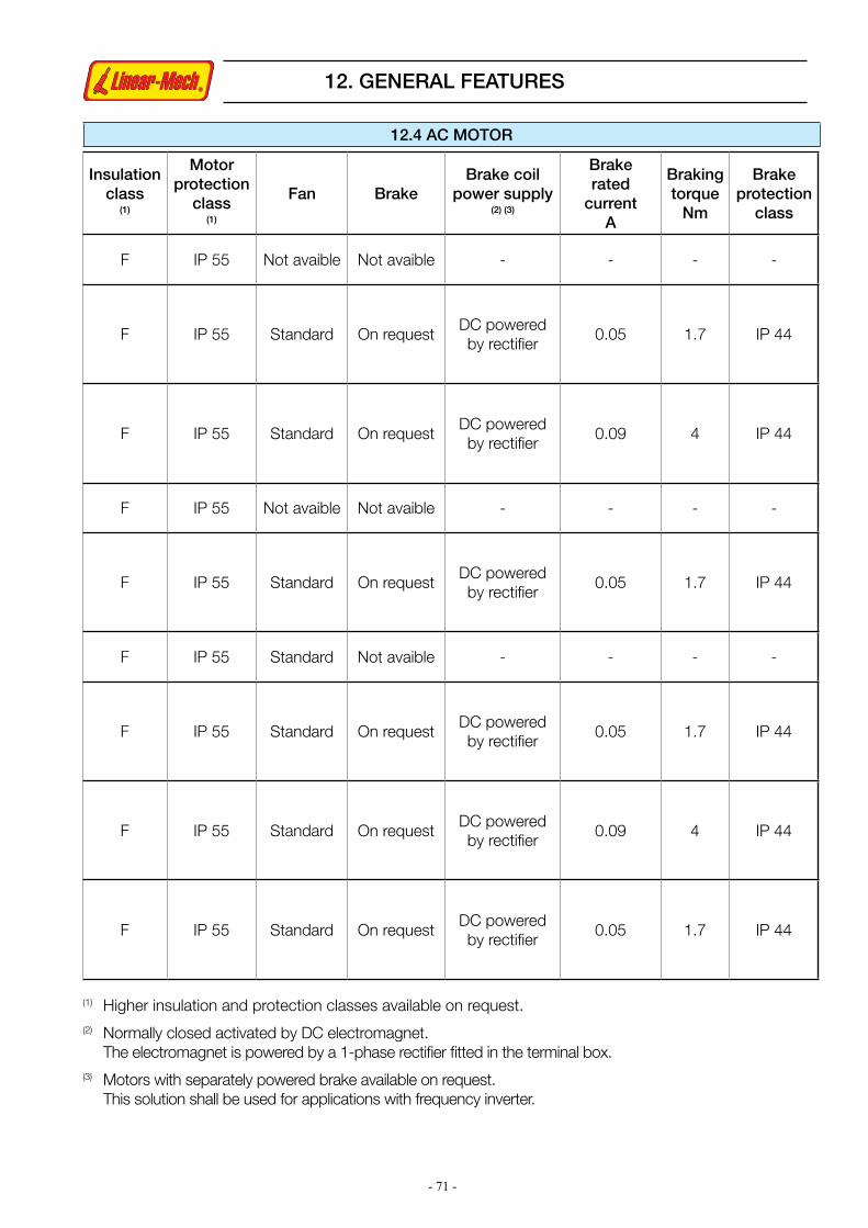
- 71 -
12. GENERAL FEATURES
(1) Higher insulation and protection classes available on request.(2) Normally closed activated by DC electromagnet. The electromagnet is powered by a 1-phase rectifier fitted in the terminal box.(3) Motors with separately powered brake available on request. This solution shall be used for applications with frequency inverter.
Insulationclass
(1)
Motor protection
class (1)
Fan BrakeBrake coil
power supply (2) (3)
Brake rated
current A
Braking torque
Nm
Brake protection
class
F IP 55 Not avaible Not avaible - - - -
F IP 55 Standard On requestDC powered by rectifier
0.05 1.7 IP 44
F IP 55 Standard On requestDC powered by rectifier
0.09 4 IP 44
F IP 55 Not avaible Not avaible - - - -
F IP 55 Standard On requestDC powered by rectifier
0.05 1.7 IP 44
F IP 55 Standard Not avaible - - - -
F IP 55 Standard On requestDC powered by rectifier
0.05 1.7 IP 44
F IP 55 Standard On requestDC powered by rectifier
0.09 4 IP 44
F IP 55 Standard On requestDC powered by rectifier
0.05 1.7 IP 44
12.4 AC MOTOR
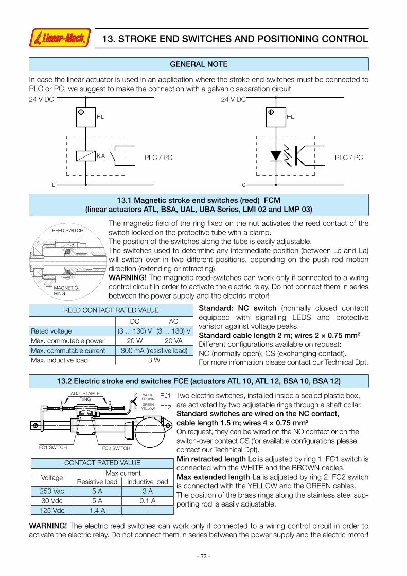
- 72 -
In case the linear actuator is used in an application where the stroke end switches must be connected to PLC or PC, we suggest to make the connection with a galvanic separation circuit.
PLC / PC
24 V DC24 V DC
PLC / PC
GENERAL NOTE
13.1 Magnetic stroke end switches (reed) FCM(linear actuators ATL, BSA, UAL, UBA Series, LMI 02 and LMP 03)
The magnetic field of the ring fixed on the nut activates the reed contact of the switch locked on the protective tube with a clamp. The position of the switches along the tube is easily adjustable.The switches used to determine any intermediate position (between Lc and La) will switch over in two different positions, depending on the push rod motion direction (extending or retracting).WARNING! The magnetic reed-switches can work only if connected to a wiring control circuit in order to activate the electric relay. Do not connect them in series between the power supply and the electric motor!
REED SWITCH
ADJUSTABLE RING
WHITE BROWN
GREEN YELLOW
FC1 SWITCH FC2 SWITCH
MAGNETIC RING
REED CONTACT RATED VALUE
DC ACRated voltage (3 ... 130) V (3 ... 130) VMax. commutable power 20 W 20 VAMax. commutable current 300 mA (resistive load)Max. inductive load 3 W
13.2 Electric stroke end switches FCE (actuators ATL 10, ATL 12, BSA 10, BSA 12)
Two electric switches, installed inside a sealed plastic box, are activated by two adjustable rings through a shaft collar.Standard switches are wired on the NC contact, cable length 1.5 m; wires 4 × 0.75 mm2
On request, they can be wired on the NO contact or on the switch-over contact CS (for available configurations please contact our Technical Dpt).Min retracted length Lc is adjusted by ring 1. FC1 switch is connected with the WHITE and the BROWN cables.Max extended length La is adjusted by ring 2. FC2 switch is connected with the YELLOW and the GREEN cables.The position of the brass rings along the stainless steel sup-porting rod is easily adjustable.
WARNING! The electric reed switches can work only if connected to a wiring control circuit in order to activate the electric relay. Do not connect them in series between the power supply and the electric motor!
Standard: NC switch (normally closed contact) equipped with signalling LEDS and protective varistor against voltage peaks.Standard cable length 2 m; wires 2 × 0.75 mm2
Different configurations available on request:NO (normally open); CS (exchanging contact). For more information please contact our Technical Dpt.
13. STROKE END SWITCHES AND POSITIONING CONTROL
CONTACT RATED VALUE
VoltageMax current
Resistive load Inductive load250 Vac 5 A 3 A30 Vdc 5 A 0.1 A125 Vdc 1.4 A -

- 73 -
STOP
Switch FC1
Cam 1
BLACK (0.75 mm²)M=
RED (0.75 mm²)
Fixing screw
Plastic support Switch FC2
Cam 2Fixing screw
Standard switches have silver-plated contacts, max. current 12 A with resistive load - 6 A with inductive load. Switches with gold-plated contacts, very low contact resistance for low working voltage (if connected to PLC or PC), max. current 0.1 A, available on request.
Following pictures show the switching sequence for switch FC2.
Each of the two micro-switches is fitted in a slot with a cam for switches commutation.A screw allows to lock the assembly in the desired position, adjusting in this way the switching position.The nut with suitable shape makes the cams rotate, so to activate the switches.This cam-operated device provides a stable and self-keeping commutation of the switches.The MIN. RETRACTED LENGTH Lc of the actuator is adjusted and controlled by switch FC1.The MAX. EXTENDED LENGTH La of the actuator is adjusted and controlled by switch FC2.
13.3 Electric stroke end switches FC (linear actuators LMR Series)
STANDARD switch connectionCode FC2: two electric cam-operated switches, wired on contact NC (to be connected into the external control circuit). On request, the switches can be wired on the contact NO or on switch-over contact CS.Code FC2X: two electric cam-operated switches, internally wired between power supply and electric motor, in order to switch off the power supply directly, without relays.
MOTORRED (0.75 mm2)BLACK (0.75 mm2)
FC 1RED (0.22 mm2)WHITE (0.22 mm2)FC 2YELLOW (0.22 mm2)GREEN (0.22 mm2)
POWER SUPPLY
13. STROKE END SWITCHES AND POSITIONING CONTROL
Plastic support

- 74 -
INT 1 - Lc position switchINT 2 - La position switchINT 3 - intermediate position switchCAM 1 - Lc position camCAM 2 - La position camCAM 3 - intermediate position camPOR - rotative potentiometer
INT 2 (1)
HAND CRANCK SHAFT
INT 2
INT 1INT 2INT 1
INT 3POR
CAM 2CAM 1
POR
13.4 Electric cam-operated stroke end switches (linear actuators CLA and CLB Series)
SWITCH RATED VALUES
VoltageMax current
Resistive load Inductive load250 Vac 21 A 12 A30 Vdc 14 A 12 A125 Vdc 0.8 A 0.6 A
CAM 3
CAM 2CAM 1
13.4 Rotative potentiometer for positioning control (linear actuators CLA and CLB Series)
Code FC2: two electric cam-operated switches, wired on contact NC (to be connected into the exter-nal control circuit). On request, the switches can be wired on the contact NO or on the switch-over contact CS. (For available configurations please contact our Technical Dpt).Code FC2X: two electric cam-operated switches, internally wired between power supply and electric motor, in order to switch off the power supply directly, without relays. Available for actuators with Dc or AC 1-phase motor.Code FC2 + FC or FC2X + FC: Stroke end switches FC2 or FC2X with a third switch for any intermediate position. The third switch can be wired on contact NC or NO on request. (For different configurations please contact our Technical Dpt).
Code POR 5k: rotative potentiometer, single turn (340°), 5 kOhm ± 20 %, linearity ± 2 %The rotative potentiometer is an absolute transducer, whose output signal is proportional to the current position of the actuator push rod. Analogic output signal.Standard cable: 4 x 0.25 mm2 + shield, 1.5 m length (for different configurations please contact us).POR 5k standard wiring diagram:
POR Power supply: 0 V dcWHITE
YELLOW
GREEN
BROWNSHIELD
Reference signal: ZERO
Reference signal: RETURN
POR Power supply: + V cc
FC2 + POR 5kFC2X + POR 5k
FC2 + FCFC2X + FC
Lc = actuator retracted length, La = Lc + Stroke – actuator extended length
13. STROKE END SWITCHES AND POSITIONING CONTROL

- 75 -
13.5 Encoder GI (linear actuators LMR 01, LMR02, LMR 03 and LMP03)
5 ÷ 24 Vdc
ChannelAEN
CO
DE
R
GI
current 20 mA
5 wires cable functionblack
0 V
Out 1 (ch.A)
Out 3 (ch.Z)
Out 2 (ch.B)
Shield
+ Vcc
green
yellow
red
blue
current 20 mA
0 V
Channel B
POWER SUPPLY
OUTPUT
13.6 Encoder EH38 (linear actuators ATL 10, UAL 0, BSA 10, UBA 0)
Hall effect, bi-directional, incremental encoderOutput configuration: PUSH-PULLCode GI 21: 2 output channels, 1 pulse per revolutionCode GI 24: 2 output channels, 4 pulses per revolutionCable length: as motor cableProtected against polarity inversionProtected against any incorrect output connectionNOTE: For conductive cables colour, please refer to the wiring diagram in the “Installation Instructions” supplied with the product.
Bi-directional, incremental, optical encoderOutput configuration: PUSH-PULLCode EH38: 2 output channels, 100 pulses per revolution, with zero set pulseCable length: 1.3 mProtected against short circuitProtected against polarity inversionProtected against any incorrect output connectionInput voltage: 8÷24 VccNo load power consumption:100 mA Max. commutable current: 50 mA per channel
NOTE: Safety clutch FS cannot be used with rotative encoder(the position reference would be lost due to its slipping).
13. STROKE END SWITCHES AND POSITIONING CONTROL

- 76 -
LME 01
14.1 LME 01 - Electronic overload protection
14. CONTROLS AND DRIVERS
TECHNICAL DATA
Model 24 V 12 V
Supply voltage [V dc] 24 12
Output voltage [V dc] 24 12
Current threshold range [A] 2 ... 10 4 ... 20
Delay time range [s] 0 ... 1.5
Max. duty cycle 15 % over 10 min
Protection class IP 30
Box material ABS
Box dimensions [mm] 89 × 64 × 30
Connection cables length: 150 mm, with fast-on connectors
ORDERING CODE EXAMPLE
LME 01 24 V ATL 02
Model Actuator connected to LME 01
Actuatorpower supplyand control
24 or 12 V DC
CURRENT THRESHOLD SETTING
DELAY TIME SETTING
BLUE
DC motor 24 or 12 V
BROWN
24 or 12 V DC
BROWNBLUE
LME 01 is an electronic device that protects DC motors against current overloads due to a persistent dynamic overload applied on the actuator.
The electronic protection LME 01 is suitable for all LINEARMECH actuators with DC motor.
LME 01 is connected between electric motor and power supply.
An electronic circuit inside monitors the input current and, as this reaches the preset threshold value, LME 01 cuts it off.
A trimmer enables the threshold current value adjustment within a continuous range.
Protection intervention can be delayed to allow the motor start. This delay time can be set within a continuous range with a trimmer.
Turn off the power supply to reset the device.
The electronic circuit is inside a plastic box with flats for easy mounting.

- 77 -
LME 02
Small size DC motors fitted on many of Linearmech actuators are not available with mechanical brake (operation and/or static brake). There is no accuracy on actuator’s stop position without the mechanical brake on the motor, when switching off the power on motor itself. The uncertainty depends on the speed, the load inertia and other factors such as actuator’s performances and efficiency.Thanks to the new Linearmech LME 02 control is possible to: power supply the actuator with 12 or 24Vdc; manage electromechanical limit switches (FCE, FC2) or magnetic limit sensors (FCM); dynamic braking the actuator when the motor is switched off, by closing in short circuit the motor (slowing down the motor rotor and the load).When the motor is switched off, it is closed in short circuit. This condition, with the actuator in still position, increases the self-locking capacity of the actuator. This is an help to hold the position and the load even when the ratio and the pitch of linear actuator’s screw are non self-locking. When the “Electronic dynamic braking” does not ensure the desired accuracy, it is recommended to use different solutions with brake motors. The “Electronic dynamic braking” is more effective on low speed linear actuators. The effectiveness lowers while speed and efficiency increase (acme screws with more starts or ball screws).Please contact our Technical Dept. for more details.The LME 02 control device can be connected to the actuator according to the following wiring diagrams.
WORKING MODELME 02 device must be fitted between power supply and actuator motor according to the above wiring diagrams. Actuator push rod moves forward (FW) or reverse (REV), depending on power supply polarization on LME02 input pins.Powering on this device the actuator push rod moves. The actuator stops when power supply is switched off or limit switches positions are reached (same running conditions as per actuators with FC2X but with the advantege that switches do not cut off the motor current). In both conditions, the “Electronic dynamic braking” is active. The braking is held even without power supply.The switch FC2X (see pages 73 and 74) is an internal wiring between power supply and electric motor in order to switch off the power supply directly, without relays, when the limit positions are reached.
14. CONTROLS AND DRIVERS
Input pin “P” -> + Vdc FWmovementInput pin “N” -> 0 Vdc
Input pin “P” -> 0 Vdc REVmovementInput pin “N” -> + Vdc
FC2 + Dynamic braking FCM + Dynamic braking
FC2 + Dynamic braking Dynamic braking only
Brown
Brown
Red
Red
Black
Brown
Red or Brown
Blue
White
White
Green
Green
Blue
Black or Blue
Blue
Brown
Yellow
Yellow
Limit - switchInputsShortcircuitedPower
supplyInput
PowersupplyInput
PowersupplyInput
PowersupplyInput
All models
TECHNICAL FEATURES Power supply 12 or 24 Vdc Peak current 15 A
Nominal current 10 A Intervention time 20 ms
14.2 LME 02 - Electronic dynamic braking
P
P
P
P
CLA-CLB
N
N
N
N
M+
M+
M+
M+
Lc+
0.75 mm2
0.25 mm2
0.75 mm2
0.22 mm2
0.75 mm2
0.75 mm2
0.75 mm2
0.25 mm2
0.75 mm2
0.22 mm2
0.25 mm2
0.75 mm2
0.22 mm2
0.75 mm2
0.75 mm2
0.75 mm2
Lc+
Lc+
Lc+
Lc-
Lc-
Lc-
Lc-
La+
La+
La+
La+
La-
La-
La-
La-
M-
M-
M-
M-
ATL-BSALMR0.25 mm2 0.22 mm2

- 78 -
LME 11
LME 11 is a programmable driver for a single actuator with DC motor. It allows to control the linear actuator push rod position and the linear speed, as well as the maximum force. Furthermore, starting-stopping ramp time, max. speed and required push rod position can be set. Two stroke end switches prevent mechanical stop at the end of the stroke. LME 11 allows also to monitor the input current and to cut it off in case of overload during linear motion. Protection intervention and delay time can be set with a trimmer.LME 11 can control a linear actuator with DC motor, two normally closed stroke end switches and a feedback device: rotative potentiometer (single turn, 5 kOhm) or bi-directional encoder or 1-channel pulse generator (PUSH-PULL / OPEN COLLECTOR, max. 1 kHz).The system driver-linear actuator can work in different ways, depending on software parameters value. Generally, the unit is supplied with three different closed loop working modes already stored.
14. CONTROLS AND DRIVERS
14.3 LME 11 - Single actuator programmable driver
Working mode 0The push rod actuator can be set in three different preset positions L (input N) between two software limit positions Lc (SW) and La (SW), within the range limited by two stroke end switches - Lc (FC) and La (FC) positions).The motor supply is activated by the signal CYCLE START+ input N and automatically stopped when the push rod reaches the set position L (input N).
Working mode 1The push rod actuator can be set in any position L between two software limit positions Lc (SW) and La (SW), within the range limited by two stroke end switches - Lc (FC) and La (FC) positions.The motor runs only when the signal CYCLE START+ input N is on (JOG mode).
Working mode 2The push rod actuator can be set in position L defined by an external, analog reference signal (potentiometer or any other device with output 0 ... 5 V dc or 4 ... 20 mA) between two software limit positions Lc (SW) and La (SW), within the range limited by two stroke end switches - Lc (FC) and La (FC) positions);Varying the reference signal level, the actuator motor runs automatically until the push rod reaches the set position.Other working modes can be obtained with a different software.

- 79 -
LME 12
14.4 LME 12 - Two-actuators programmable driver
The synchronization of two actuators is extremely important in those applications requiring the movement of covers, traps or hoods. A non-synchronized movement of the actuators would cause loads and/or deformations on the units. LME 12 driver integrates both control and activation functions allowing the implementation of dedicated software solutions depending on application requirements. LME 12 is a programmable driver for synchronizing two linear actuators with DC motors. LME 12 is a single board which integrates two LME 12 driver units. Each actuator is provided with a microprocessor with its relevant parameters set.Based on the preset parameter values, LME 12 calculates the time related position of the actuator push rod. Startup, it makes the two actuators move simultaneously and, based on to the feedback signals, it monitors the current position of both push rods.
§ Rated input voltage: 24 V dc or 12 V dc§ Input voltage limits: (10 ...30) V dc§Automatic shut-off in case of input voltage lower than preset value (important when the driver is powered by battery) §Protected against input polarity inversion§Max input current:10 A§Automatic shut-off in case a preset temperature value is reached (over-heating protection)§ Emergency input§Movement enabling input§ 3 positioning drive inputs§Analogic input (V or mA)§ Encoder input (max. frequency 1 kHz)§MODBUS communication port§Status output for system functioning monitoring§Signal LEDS§Dimensions LME 11: 144 x 107 x 76 mm§Dimensions LME 12: 116 x 160 x 76 mm§ Fixing on rail DIN-EN 50022
General note about working modes:All software parameter values can be varied using an additional display (available on request) or through MODBUS communication port.
14. CONTROLS AND DRIVERS
LME 11 and LME 12 - Technical features
The system will stop automatically and an error signal will appear in the following two cases:§ the difference between the real position of any of the two push rods and the corresponding calculated position is higher than preset value;§ the difference of the real position between the two push rods is higher than another preset value.Two drivers LME 12 can be connected into a 4-axis system.Working modes: see chapter about LME 11.

- 80 -
15. INSTALLATION AND COMMISSIONING
Transport and HandlingLinearmech electromechanical actuators are very robust products, since they are structurally built with metallic components; nevertheless, motors provided with their protections, stroke end switches and encoders require a particular care and attention in packaging and during transport and handling.Therefore, we recommend to handle the actuators using their supporting points, such as the housing, and not the stroke end devices or motor. Finally, we recommend not to bang the actuators one against the other or against machine surfaces. The electric components of stroke end switches, encoders and motors must be handled with care!StorageDuring storage, electro-mechanical actuators shall be protected against atmospheric agents and dust or other polluters settling on the push rod.We recommend to store the products in environment temperature range within (-10 ... +40) °CInstallationLinear actuators must be installed to work with push or pull axial load only.Lateral and radial loads are not permissible. The front and rear fixing attachments must be aligned!
Ball joint front attachment is recommended in case the alignment of front and rear fixing points cannot be guaranteed. An incorrect installation can cause loss of power, malfunctioning, noise and lubricant leakage. The actuator minimum retracted length (Lc) and maximum extended length (La) are the operation limits.Make sure that the application does not require a stroke length longer than the one fixed by these limits. The use of the actuator exceeding its max. extended length (La) and min. retracted length (Lc) and the pro-vided internal protections, cause collision against the mechanical stops with consequent possible damage of screw and bronze nut. Commissioning and use Linearmech linear actuators are supplied with long-life lubricant and therefore maintenance-free. Before activating the actuator, the following checks must be carried out:§ Verify the motor shaft turning direction (motor wiring connection) and the related push rod travelling direction. Wires connection related to the push rod travelling direction is shown on page 69, in the section concerning electric motors wires connection.§ Verify the stroke end switches position: the minimum limit Lc nor the maximum limit La can be exceeded.§ Make sure that the electric motor and the stroke end switches are connected correctly and that the right voltage is used. During commissioning and tests, do not exceed the working conditions stated for each actuator as allowed duty cycle in % over 10 minutes. Any misuse can cause over-heating and unintentional premature damaging.For further explanations and in case of doubts please contact Linearmech S.r.l.The compliance failure of any recommended and suggested instructions for handling, storage, installation, commissioning and use of the product implies the immediate lost of warranty.