080811 planning and design of l.i.s.s
TRANSCRIPT
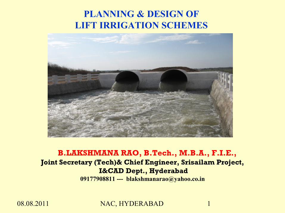
08.08.2011 NAC, HYDERABAD 1
PLANNING & DESIGN OF LIFT IRRIGATION SCHEMES
B.LAKSHMANA RAO, B.Tech., M.B.A., F.I.E.,Joint Secretary (Tech)& Chief Engineer, Srisailam Project,
I&CAD Dept., Hyderabad09177908811 --- [email protected]

08.08.2011 NAC, HYDERABAD 2
PROJECT WISE AYACUT IRRIGATED IN KHARIF 2010-11 and proposed in Rabi 2010-11
Area in acres Area in acres
Sl.No Name of the Project Total Aycut
Ayacut Irrigated in Kharif
Ayacut Proposed for Rabi
Sl.No
Name of the Project
Total Aycut
Ayacut Irrigated in
Kharif
Ayacut Proposed for
Rabi
1 2 3 5 6 1 2 3 5 6
1 Nagarjuna Sagar 2153094 2117000 621000
20Godavari Delta System 1038362 986000 896000
21Krishna Delta System 1335100 1300000 524000
2A.M.R.P (SLBC) 195521 184539 22Yeleru 67614 53000 530003Musi 30000 30000 23Vamshadhara 226199 147000 4Priyadarshini Jurala 107143 116000 68500 24Tarakarama LIS 4563 4563
5R.D.S 87183 30000 10500 25Gundlakamma Project 40000 5000
6Nizamsagar 231339 190000 190000 26Tadipudi LIS 100000 125000 7S.R.S.P-1 956548 632640 887022 27Kovvadakalva 15000 15000 8S.R.S.P-2 160000 75000 28Chagalnadu 35614 20000 9J.C.Rao DLIS 20000 45000 29Pushkara LIS 86094 34127 10Kaddam 68849 68000 34500 30Venkatanagaram 34000 2250 11TBP HLC 313400 80000 31Surampalem 14150 14150
12TBP LLC 151134 168000 39000 32Pennar Delta System 247000 247000 247000
13K.C.Canal 287400 265628 111754 33Somasila Project 176000 176000
14S.R.B.C 183936 123076 30000 Major Irrigation Total 8899334 7342882 4067276
15Telugu Ganga 400110 115000 115000 Medium Irrigation 837518 570215 104655
16Guru Raghavendra 3793 3793 Minor Irrigation 4669650 2350000 65000017Thandava Reservoir 51466 45068 30000 APSIDC 899503 595769 18Narayanapuram Anicut 39178 35898 30000 Grand TOTAL 1.5E+07 10858866 482193119Nagavali 39544 39150 30000

08.08.2011 NAC, HYDERABAD 3WALAMTARI, HYDERABADWALAMTARI, HYDERABAD 33
AYACUT DETAILS UNDER L.I.SCHEMES
PUSHKARA L.I.S. - 1,85,906 Ac TADIPUDI L.I.S. - 68,600 Ac RAJIV SAGAR L.I.S. - 4,00,000 Ac ALISAGAR L.I.S. - 53,793 Ac GUTPAH L.I.S. - 38,793 Ac RAJIV BHIMA L.I.S. - 2,03,000 Ac NETTAMPADU L.I.S - 2,00,000 Ac KALWAKURTHY L.I.S. - 3,40,000 Ac H.N.S.S. L.I.S. - 6,21,000 Ac
08.08.2011 NAC, HYDERABAD 4
Introduction Rain is decentralized and so is the demand but the
supply has not been decentralized
Prevailing situation is widening socio-economic
conditions between regions resulting imbalance.
There are regions situated at higher altitudes to
which gravity is not possible or site conditions at
source do not permit dam / barrage
Lift irrigation schemes gained greater significance
in the changed scenario as provision of conventional
irrigation structures is exhausted.

08.08.2011 NAC, HYDERABAD 5
Dams & Barrages have problems of :Dams & Barrages have problems of :
SubmersionSubmersion Rehabilitation Rehabilitation Land AcquisitionLand Acquisition Environment ClearanceEnvironment Clearance Inter-state disputesInter-state disputes Most important they consume more time for completion. Most important they consume more time for completion.
Major irrigation structures need huge financial support Major irrigation structures need huge financial support and and often the estimated cost gets multiplied due to often the estimated cost gets multiplied due to delay in the completiondelay in the completion. .

08.08.2011 NAC, HYDERABAD 6
Reasons for Opting Lift Schemes Over Gravity SchemesReasons for Opting Lift Schemes Over Gravity Schemes:: In the present circumstances, In the present circumstances, lift irrigation schemes assumed lift irrigation schemes assumed
greater significance and seems to be the only viable solutiongreater significance and seems to be the only viable solution to to meet the aspirations of the upland people for the following reasons :meet the aspirations of the upland people for the following reasons :
Speedy Completion of the SchemeSpeedy Completion of the Scheme Lesser initial CostLesser initial Cost No need of extensive and time investigationNo need of extensive and time investigation Flexibility of Location of Head worksFlexibility of Location of Head works Does not have foundation problemsDoes not have foundation problems Environmental friendlyEnvironmental friendly
Though lift irrigation schemes have some drawbacks and are costly, Though lift irrigation schemes have some drawbacks and are costly, in the prevailing situation, they are inevitable since the situation in the prevailing situation, they are inevitable since the situation demands them in the contemporary irrigation planning, but ought to demands them in the contemporary irrigation planning, but ought to be taken up judiciously.be taken up judiciously.

08.08.2011 NAC, HYDERABAD 7
Limitations of L.I. Scheme Limitations of L.I. Scheme They are costly with respect to benefit cost ratio They are costly with respect to benefit cost ratio
compared to Gravity schemes compared to Gravity schemes Require assured un-interrupted power supply. Always Require assured un-interrupted power supply. Always
dependent on power supplydependent on power supply Require assured flows from the sourceRequire assured flows from the source Recurring cost on power billsRecurring cost on power bills Regular maintenance is required for civil as well as Regular maintenance is required for civil as well as
mechanical works. Any problems in pipes or pumps lead mechanical works. Any problems in pipes or pumps lead to grinding halt to the system to grinding halt to the system
Life of L.I. scheme is shorter than dams & barragesLife of L.I. scheme is shorter than dams & barrages Need periodical replacement of mechanical & electrical Need periodical replacement of mechanical & electrical
components components

08.08.2011 NAC, HYDERABAD 8
Objectives of LI Schemes
Diversion of flood water to upland areas
Supplying water to needy regions located far away
from source
Feeding tanks for future needs
Effective usage of water stored in reservoirs
Optimum utilization of water by supplying designed
quantity
Interlinking of rivers
Transfer of surplus water from reservoirs to the
required regions.

08.08.2011 NAC, HYDERABAD 9
VARIOUS COMPONENTS OF LI SCHEMESVARIOUS COMPONENTS OF LI SCHEMES
I) Civil Structure & Associated components / I) Civil Structure & Associated components / provisionsprovisions
II ) Electro-Mechanical andII ) Electro-Mechanical and
III) Hydro-MechanicalIII) Hydro-Mechanical
08.08.2011 NAC, HYDERABAD 10
I) Civil Structure & Associated components / I) Civil Structure & Associated components / provisionsprovisions
Approach CanalApproach Canal Intake / Sump / Fore bay / Surge poolIntake / Sump / Fore bay / Surge pool Sub structure / sumpSub structure / sump Super structure to accommodate Pumps & MotorsSuper structure to accommodate Pumps & Motors Service / maintenance bayService / maintenance bay Control panel roomControl panel room Dewatering Pumps chamber arrangementDewatering Pumps chamber arrangement
08.08.2011 NAC, HYDERABAD 11
Balancing Reservoirs / tanksBalancing Reservoirs / tanks
Delivery CisternDelivery Cistern
Gravity Canal with CM & CD worksGravity Canal with CM & CD works

08.08.2011 NAC, HYDERABAD 12
II) Electro – MechanicalII) Electro – Mechanical
Pumps & MotorsPumps & Motors Control PanelsControl Panels SCADASCADA TransformersTransformers Dewatering PumpsDewatering Pumps EOT crane for Pumps HOPDV / NRV / EOPDV etc within pump house
08.08.2011 NAC, HYDERABAD 13
III) Hydro – MechanicalIII) Hydro – Mechanical
Pressure mains with design diameter and thickness Pressure mains with design diameter and thickness Surge Protection Devices based on the surge analysisSurge Protection Devices based on the surge analysis Valves such as air valves at regular intervalsValves such as air valves at regular intervals Stop logs & Trash racks Stop logs & Trash racks Manifold to connect for smooth distribution of Manifold to connect for smooth distribution of
discharge from delivery pipes of pumps into pressure discharge from delivery pipes of pumps into pressure mains mains
Semi Portal crane for Stop logs & Trash racks

08.08.2011 NAC, HYDERABAD 14
Pump House for Wet Pit / VT Pump in River Pump House for Wet Pit / VT Pump in River

08.08.2011 NAC, HYDERABAD 15
Planning & Design Of LI Schemes
I. I. Hydrology
II. Alignment
III. Hydraulic Particulars
IV. Pumps – type, number & capacity
V. Intake Sump / Surge pool / Fore bay
VI. Design of Pump House
VII. Pressure mains / Water conductor system
08.08.2011 NAC, HYDERABAD 16
Planning & Design Of LI Schemes
VIII. Surge protection system
IX. Delivery Cistern / Out fall structure
X. SCADA – Supervisory ( Sequential )
Control And Data Acquisition
XI. Canal networking system

08.08.2011 NAC, HYDERABAD 17
HYDROLOGY
Design Discharge shall be computed for :Crop Water requirementSeepage & Evaporation LossesDrinking Water requirementOperation period of Pumps ( Preferably 24 hrs )
Low Water Level shall be :Above bed level of sourceAbove MDDL of reservoirs at river intakeFor pump houses far away from source, conveyance losses shall be deducted from LWL / MDDL of source

08.08.2011 NAC, HYDERABAD 18
SRIPADA YELLAMPALLI RERSERVOIR

08.08.2011 NAC, HYDERABAD 19
AMRP – SURGE POOL
Size : 20mX50mX62m

08.08.2011 NAC, HYDERABAD 20
08.08.2011 NAC, HYDERABAD 21
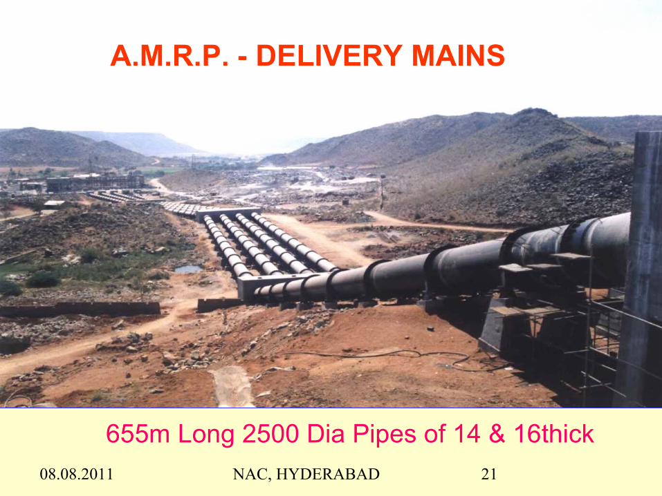
A.M.R.P. - DELIVERY MAINS
655m Long 2500 Dia Pipes of 14 & 16thick

08.08.2011 NAC, HYDERABAD 22

08.08.2011 NAC, HYDERABAD 23
ALI SAGAR L.I.S PUMP HOUSE 3

08.08.2011 NAC, HYDERABAD 24
HANDRI NEVA SUJALA SRAVANTI L.I.S.

08.08.2011 NAC, HYDERABAD 25
ALI SAGAR L.I.S. DELIVERY CISTERN STAGE - I
08.08.2011 NAC, HYDERABAD 26
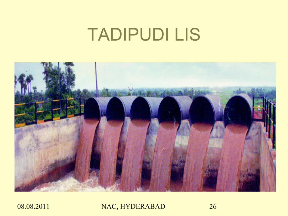
TADIPUDI LIS
08.08.2011 NAC, HYDERABAD 27
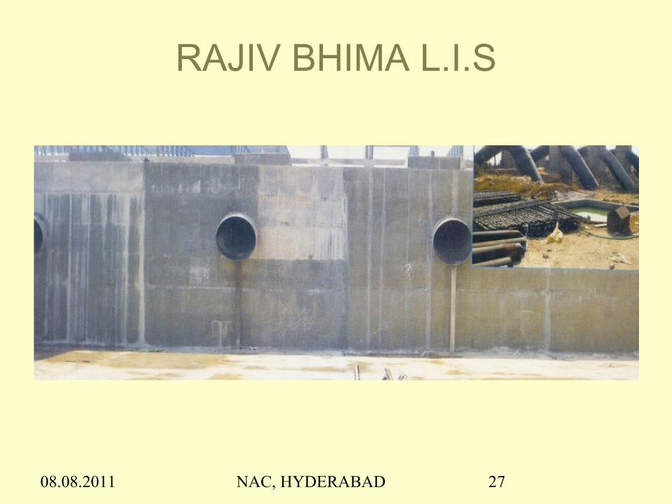
RAJIV BHIMA L.I.S
08.08.2011 NAC, HYDERABAD 28
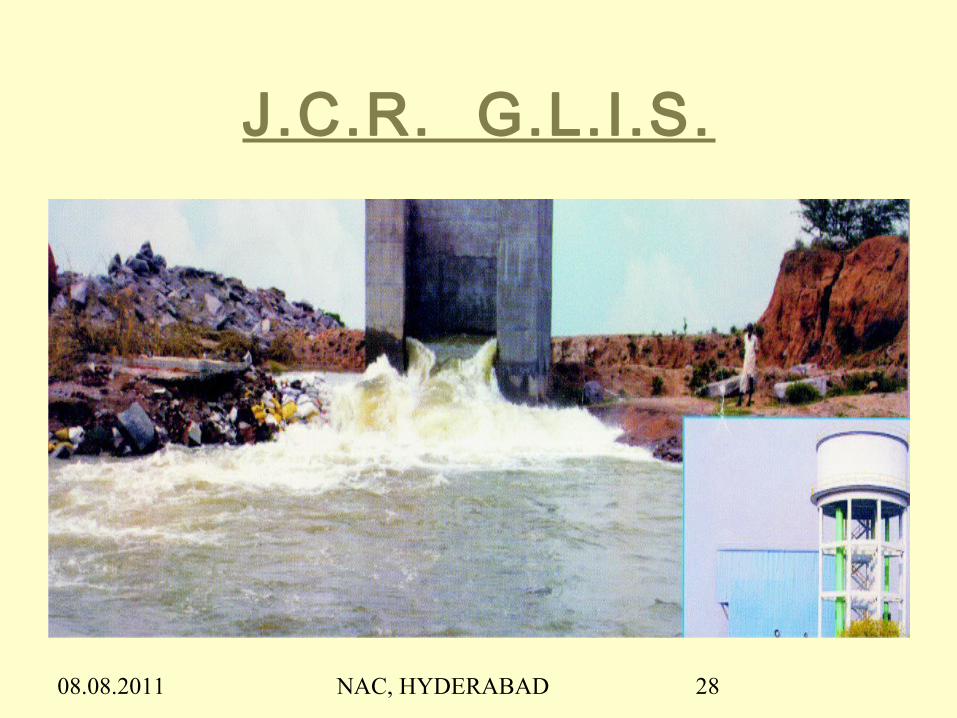
J.C.R. G.L.I.S.
08.08.2011 NAC, HYDERABAD 29
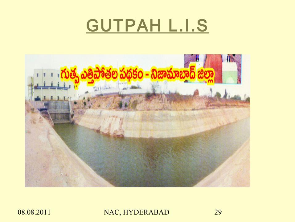
GUTPAH L.I.S

08.08.2011 NAC, HYDERABAD 30
Fixing of LWLFixing of LWL
Whenever pumping is proposed from a reservoir, Whenever pumping is proposed from a reservoir,
LWL shall be above the MDDL, otherwise the LWL shall be above the MDDL, otherwise the
following draw backs will be there :following draw backs will be there :
Encroachment into dead storageEncroachment into dead storage
Has impact on already committed ayacut of projectHas impact on already committed ayacut of project
Reservoir takes extra time to get filled up and Reservoir takes extra time to get filled up and
cannot give water to committed ayacut in time, cannot give water to committed ayacut in time,
during next seasonduring next season
Increases pumping head, pump capacity and also Increases pumping head, pump capacity and also
project costproject cost

08.08.2011 NAC, HYDERABAD 31
ALIGNMENT
The alignment finalisation consists of :
- Fixing of Pump house location in the foreshore
of river / reservoir
- Approach and gravity canal lengths
- Length of Pressure mains
- Utilization of tanks en route the alignment
- Number of Lifts / Pump houses

08.08.2011 NAC, HYDERABAD 32
Fixing of Pump House LocationPump house location shall be located such a way that it needs :
Smaller length of approach canal
Smaller length of approach bridge from TBL Approach Canal and Gravity CanalApproach canal capacity should be 50% more than required for river intake :
Off take point of approach shall not be silt accumulation region as it is the gate way of the LIS
Greater length of gravity canals has to be explored to achieve economy by reducing pipe length.
08.08.2011 NAC, HYDERABAD 33
Length of Pressure mains
Shorter length of Pressure main shall be provided
since length has bearing on cost of the scheme.
If length increases:
•- Pumping head increases there by pump
capacity
•- Pipe thickness increases
•- Surge protection devices required more
•- Capital cost increases

08.08.2011 NAC, HYDERABAD 34
Utilization of Tanks / Balancing Reservoirs ( BR )
Balancing Reservoirs make the scheme economical as well as efficient as : Design discharge of pumps
can be reduced which reduces pump capacity, pipe dia and canal sizes
Flood waters can be stored in the balancing reservoirs for future needs
Better Synchronization of lifts is possible in multiple stages of lifts

08.08.2011 NAC, HYDERABAD 35
Number of Lifts / Pump housesNumber of lifts / pump houses depend on : Length of the canal Total Pumping head required Presence of command en route the canal Capacity and type of proposed pumps
No. Disch LWL Platform Delivery Intake/Gravity Length Pipe Length
Lift ILift IILift III
Fig 1 SCHEMATIC DIAGRAM SHOWING 3 - LIFTS OF CHAGALNADU L.I. SCHEME
CBL +15.00M
+37.00
- 3.0LIFT I
+2.30+2.75
RIV
ER
+18.00AVG.G.L
LWL + 13.50+8.00
+6.50
+18.45
+14.00
+18.80
+22.80
M.F.L +20.80
BED LEVEL OF JACKWELL
-1.00
C.C M20GRADE
Pressure mains
+22.80
Avg. G.L
+8.00
+16.00M
Delivery IBank
FSL +18.00M
LWL + 16.715+16.00M CBL +15.00M
Delivery I
FSL +18.00M
LIFT II
+ 22.60
6.56 cumecs6.56 cumecs6.06 cumecs
+ 23.60m+ 41.30m+ 60.60m
20.00m4540.0m4080.0m
+ 22.80m+ 22.60m+ 46.25m
+ 13.00m+ 16.715m+ 38.795m
200.0m1350.0m525.0m
LWL + 38.795FSL +40.00+41.30CBL +38.53
Delivery II
LIFT III
+ 46.25Delivery III
+60.60
08.08.2011 NAC, HYDERABAD 36
HYDRAULIC PARTICULARSAfter finalising the pump house location, the length of canal,
pressure mains are to be calculated.
HPs of the scheme w.r.t. LWL and FRL of proposed sumps
HPs of approach & gravity canals and pipe alignment.
Total quantity of water required to be lifted in specified
period
Discharge at pump house considering water requirement at
various locations en route the alignment.
If period of water availability in source is less than operation
period of scheme, balancing reservoir ought to be provided.

08.08.2011 NAC, HYDERABAD 37
PUMPS Pumps act as heart of LI Scheme and play important role in
the performance as well as efficiency of the LIS.
Designer should have a comprehensive knowledge on
availability of various types of pumps and their applications
along with their limitations.
Any wrong judgment in selection of pumps may lead to
procurement of unsuitable pumps and the scheme may face
threat of repairs & maintenance along with non-functionality
to the design requirement of the scheme.
Higher capacity increases unnecessarily the capital cost and
power consumption. On the other hand lower capacity will
not deliver design discharge.
08.08.2011 NAC, HYDERABAD 38
Number of Pumps
Number of pumps and pump houses to be proposed
depend on :
Capacity of Pumps
Suction Lift and
Type of pumps

08.08.2011 NAC, HYDERABAD 39
Design Discharge
Total quantity of water to be pumped in the Total quantity of water to be pumped in the specified period shall be computed based on specified period shall be computed based on
1.1. Crop water requirement Crop water requirement 2.2. Seepage & Evaporation Losses Seepage & Evaporation Losses 3.3. Drinking water requirementDrinking water requirement 4.4. Pumping hoursPumping hours

08.08.2011 NAC, HYDERABAD 40
Determination Of Pumping Head
Total pumping head should be arrived with care since Total pumping head should be arrived with care since any any wrong calculation has a bearing on the wrong calculation has a bearing on the performance of the pump.performance of the pump.
Excess head may lead to un-necessary increase in Excess head may lead to un-necessary increase in pump capacity and power consumption pump capacity and power consumption
Lesser head may lead to non-functionality of the pumps Lesser head may lead to non-functionality of the pumps to design efficiency as well as design discharge.to design efficiency as well as design discharge.

08.08.2011 NAC, HYDERABAD 41
Total Pumping Head is obtained on summation Total Pumping Head is obtained on summation ofof
Static head between LWL & delivery level Frictional losses Losses due to exit, entry and bends System resistance losses due to the combined /
operation of pumps and pressure mains

08.08.2011 NAC, HYDERABAD 42
Capacity of Pumps
Capacity of pump can be calculated using formula : Pump capacity in KW = 9.81 Q H / η Pump capacity in HP = 9.81 Q H / 0.746 η( Motor capacity may be 10% to 20% more than pump capacity ) Where Q = Discharge in cumecs
H = Hst + Hf + Hb = Total pumping head in mη = Efficiency of pump

08.08.2011 NAC, HYDERABAD 43
The frictional losses in the pressure main is to be calculated using Hazen-William’s formula :
Hf = L ( 1.778 V / C R0.63 )1.852 Where V = Velocity in pipe ( m/s )
R = Hydraulic Radius (m) = D/4 C = Hazen William’s Coefficient = 130 for PSC pipes
= 130 + 0.17 d ( dia in inches ) for MS pipes with lining
It is desirable to limit the C value to 130 only.
08.08.2011 NAC, HYDERABAD 44
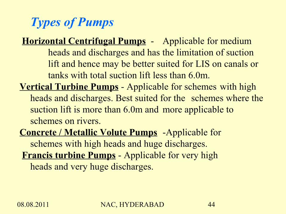
Types of Pumps
Horizontal Centrifugal Pumps - Applicable for medium heads and discharges and has the limitation of suction lift and hence may be better suited for LIS on canals or tanks with total suction lift less than 6.0m.
Vertical Turbine Pumps - Applicable for schemes with high heads and discharges. Best suited for the schemes where the suction lift is more than 6.0m and more applicable to schemes on rivers.
Concrete / Metallic Volute Pumps -Applicable for schemes with high heads and huge discharges.
Francis turbine Pumps - Applicable for very high heads and very huge discharges.

08.08.2011 NAC, HYDERABAD 45
Factors for deciding type Of PumpsFactors for deciding type Of Pumps
Type of pumps to be adopted is governed by :Type of pumps to be adopted is governed by : Hydraulic requirement such as discharge and Hydraulic requirement such as discharge and
total pumping headtotal pumping head Pump house locationPump house location Suction liftSuction lift Total pumping headTotal pumping head Pump capacityPump capacity Manufacturing limitations of respective pumps Manufacturing limitations of respective pumps

08.08.2011 NAC, HYDERABAD 46
Horizontal Centrifugal PumpsHorizontal Centrifugal Pumps
Used for medium head & discharges. Used for medium head & discharges. Useful to lifting from canals or for smaller Useful to lifting from canals or for smaller
discharges.discharges. Have limitation of suction lift. Have limitation of suction lift. Usually the suction lift is not allowed Usually the suction lift is not allowed
more than 6.0 – 6.5m more than 6.0 – 6.5m

08.08.2011 NAC, HYDERABAD 47
Horizontal Centrifugal Pumps
-When Suction lift is less than 6.0m-Applicable for lifting from Canals- For low heads and low discharges

08.08.2011 NAC, HYDERABAD 48
Arrangement of Horizontal Centrifugal Pump House

08.08.2011 NAC, HYDERABAD 49
Vertical Turbine PumpsVertical Turbine Pumps
When the site conditions are not When the site conditions are not favourable for horizontal centrifugal favourable for horizontal centrifugal pumps, i.e., whenever the suction lift is pumps, i.e., whenever the suction lift is more than 6.0m, VT pumps are more more than 6.0m, VT pumps are more suitable. suitable.
Vertical Turbine pumps are most widely Vertical Turbine pumps are most widely used in the LI schemes due to their used in the LI schemes due to their capacity to lift wide ranges of discharges capacity to lift wide ranges of discharges & heads.& heads.

08.08.2011 NAC, HYDERABAD 50
Limitations Of VT Pumps :
They are not preferred for discharges more than 10 cumecs and total head more than 75.0m.
If the head fluctuation is more than 20m, they may not function efficiently with shaft length more than 20.0m, they develop operational & vibration problems.
08.08.2011 NAC, HYDERABAD 51
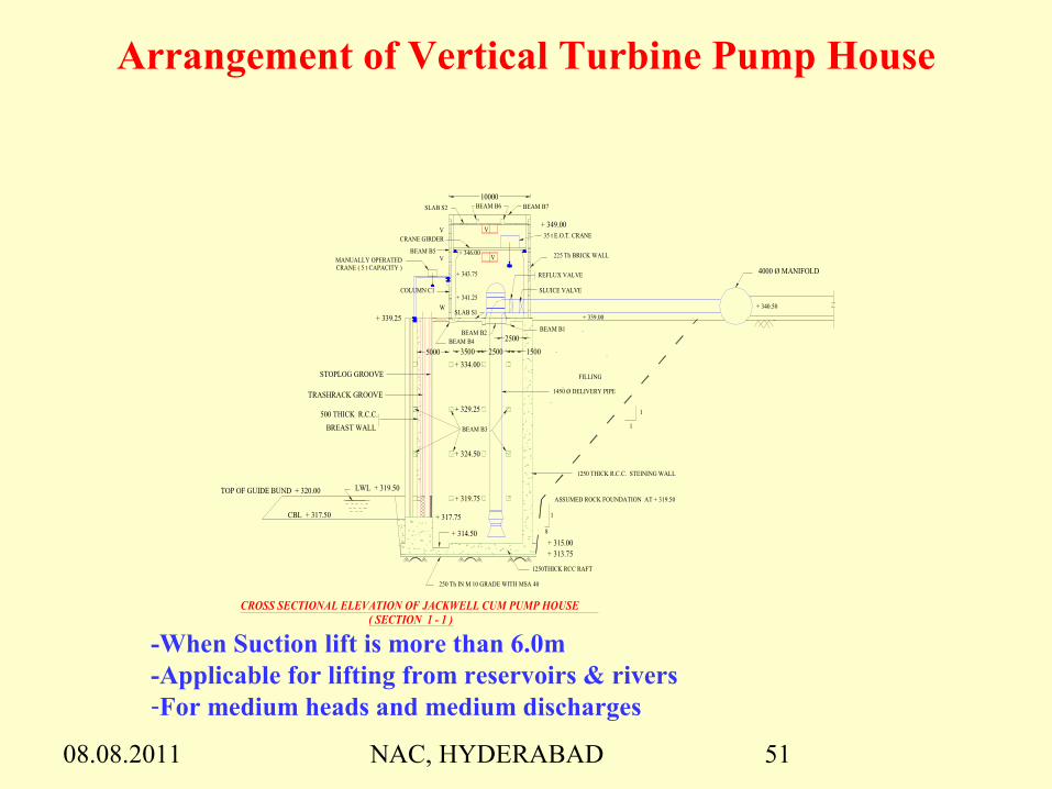
Arrangement of Vertical Turbine Pump House
CRANE GIRDER
1450 Ø DELIVERY PIPE
LWL + 319.50TOP OF GUIDE BUND + 320.00
+ 317.75
+ 314.50
REFLUX VALVE
SLUICE VALVE
8
1
STOPLOG GROOVE
TRASHRACK GROOVE
BREAST WALL
35 t E.O.T. CRANE
+ 341.25
+ 343.75
FILLING
BEAM B3
BEAM B2 BEAM B1
BEAM B4
BEAM B5
BEAM B6 BEAM B7
W
V
V
250 Th IN M 10 GRADE WITH MSA 40
MANUALLY OPERATED CRANE ( 5 t CAPACITY )
+ 339.25
+ 315.00+ 313.75
+ 339.00
+ 349.00
+ 319.75
+ 324.50
+ 329.25
+ 334.00
+ 346.00
+ 340.50
4000 Ø MANIFOLD
CBL + 317.50
2500
5000 3500 2500 1500
CROSS SECTIONAL ELEVATION OF JACKWELL CUM PUMP HOUSE ( SECTION 1 - 1 )
V
V
10000
225 Th BRICK WALL
1
1
ASSUMED ROCK FOUNDATION AT + 319.50
SLAB S1
SLAB S2
COLUMN C1
500 THICK R.C.C.
1250THICK RCC RAFT
1250 THICK R.C.C. STEINING WALL
-When Suction lift is more than 6.0m-Applicable for lifting from reservoirs & rivers-For medium heads and medium discharges

08.08.2011 NAC, HYDERABAD 52
VERTICAL TURBINE PUMPS

08.08.2011 NAC, HYDERABAD 53
Concrete Volute Pumps These pumps are almost similar to dry pit pumps These pumps are almost similar to dry pit pumps
arrangementarrangement Cannot be used for unlimited capacities / huge Cannot be used for unlimited capacities / huge
magnitudes though can be used for capacities more than magnitudes though can be used for capacities more than Vertical turbine pumps.Vertical turbine pumps.
Technically, they are end suction pumps erected vertically Technically, they are end suction pumps erected vertically with extended / lengthy shaft in between pump and motor.with extended / lengthy shaft in between pump and motor.
Useful for discharge of each pump upto 10 cumecs and Useful for discharge of each pump upto 10 cumecs and head is less than 150mhead is less than 150m
Volute Pumps with head more than 50.0m need metallic Volute Pumps with head more than 50.0m need metallic lining of volute and may be imported.lining of volute and may be imported.
Discharge control is not possible and need more power Discharge control is not possible and need more power even for reduced discharge ( unlike Francis turbine )even for reduced discharge ( unlike Francis turbine )

08.08.2011 NAC, HYDERABAD 54
CONCRETE VOLUTE PUMPSApplicable for l i f t ing from reservoirs & rivers
For high heads and high dischargesPump rating may be upto 15.0 MW
When fluctuation of water levels is > 25.0m
08.08.2011 NAC, HYDERABAD 55
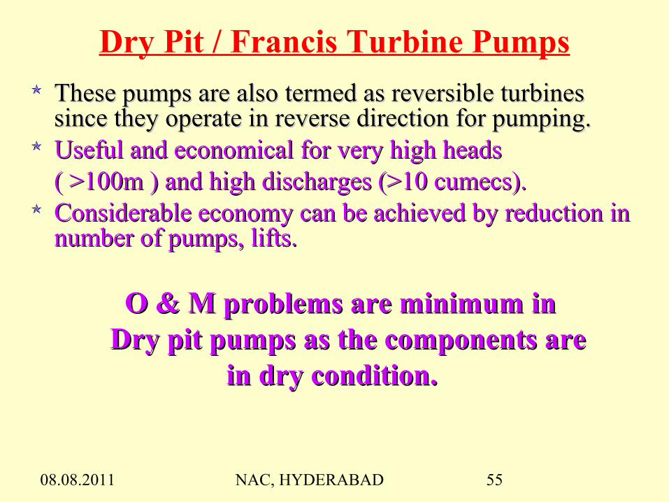
Dry Pit / Francis Turbine Pumps These pumps are also termed as reversible turbines These pumps are also termed as reversible turbines
since they operate in reverse direction for pumping.since they operate in reverse direction for pumping. Useful and economical for very high heads Useful and economical for very high heads
( >100m ) and high discharges (>10 cumecs). ( >100m ) and high discharges (>10 cumecs). Considerable economy can be achieved by reduction in Considerable economy can be achieved by reduction in
number of pumps, lifts.number of pumps, lifts.
O & M problems are minimum in O & M problems are minimum in Dry pit pumps as the components areDry pit pumps as the components are
in dry condition. in dry condition.

08.08.2011 NAC, HYDERABAD 56
These pumps are going to play vital role in the interlinking of rivers where it is required to lift huge quantity of water to very high heads.
Lift requirement of head less than 100m and discharge less than 10 cumecs, adoption ofthese pumps are un-economical for following reasons Require very big pump house Need surge pool (not required for other pumps ) Huge concreting Heavy gantry
These pumps were installed in AMRP to lift 68 cumecs to a head of 102m to irrigate 2.2 lakh acres using 4 pumps of 19 MW(each)
08.08.2011 NAC, HYDERABAD 57
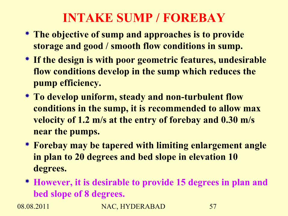
INTAKE SUMP / FOREBAY The objective of sump and approaches is to provide
storage and good / smooth flow conditions in sump. If the design is with poor geometric features, undesirable
flow conditions develop in the sump which reduces the pump efficiency.
To develop uniform, steady and non-turbulent flow conditions in the sump, it is recommended to allow max velocity of 1.2 m/s at the entry of forebay and 0.30 m/s near the pumps.
Forebay may be tapered with limiting enlargement angle in plan to 20 degrees and bed slope in elevation 10 degrees.
However, it is desirable to provide 15 degrees in plan and bed slope of 8 degrees.

08.08.2011 NAC, HYDERABAD 58 1212
0.5D
2D
0. 5D
L = 4 TO 10D
D
0.25DV < 0.3 m/sec
D
0.5D
B ell mouth
L .W.L
S = 1.5D(mini)
dSINGLE P UMP SUMP
0. 75D TO 1D
T
W = 6D + 2T
2/ 3WLe vel floor
D
v < 0. 3m/ secv > 1. 2m/sec
> 20
Down slope> 10°
d
S = 1.5D(mini) 0.5D
D
L .W.L
Bell mouth
0.75 to 1D
>10°
2/3 W
MULTIPLE PUMPS SUMP
C.B.L
Good features of sump design: Whered = Diameter of column assemblyD = Diameter of bowl assemblywhich is usually in the range 1.5dto 1.8dT = Thickness of baffle wall / pierGood features:
• Bell mouth near to sump floor; c = 0.5D.• Flat sump floor.• Width about 2D.• Submergence below LWL not less than 1.5D(mini).• Length of approach shall not be less than 4D and preferably up to 10D in case of single pump sump and 2/3W in case of multiple pumps sump.• Distance of rear wall from pump X = 0.25D in case of single pump sump and 0.75D to 1.0D in case of multiple pumps sump.• In any case, mean velocity of flow approaching bell mouth should be 0.3m/sec or less.

08.08.2011 NAC, HYDERABAD 59
Forebay sides on water side shall be vertical
( atleast upto LWL ) as slopes will cause off
sets at pump house generating vortices.
Jump formation shall be strictly avoided near
pumps as it creates turbulence.
Proposals of intake sump for major LIS shall
be ascertained by physical sump model studies
for fine tuning of the flow conditions and
satisfied, before commencement of execution.
Intake sumps in the river foreshore shall be
provided with controlling arrangement at
entry of forebay also to facilitate maintenance
of the sump, in addition to gates provision in
front of the pumps.

08.08.2011 NAC, HYDERABAD 60
ALI SAGAR- Intake Sump & Pump House

08.08.2011 NAC, HYDERABAD 61
DESIGN OF PUMP HOUSE
Wet Pit Pump House- The pump will be submerged in water. Substructure will be always in water
Ex : Pump house with Vertical turbine pumps.
Dry Pit Pump House- It is also called as reversible turbine. Access can be there to all the components including pumps. Substructure will be without water and in dry condition. Hence maintenance is very easy.
Ex : Francis turbines and Volute Pumps

08.08.2011 NAC, HYDERABAD 62
I) Pump House / Pumping StationI) Pump House / Pumping Station Approach CanalApproach Canal Intake / Sump / Forebay / Surge poolIntake / Sump / Forebay / Surge pool Sub structure / sumpSub structure / sump Super structure to accommodate Pumps & Super structure to accommodate Pumps &
MotorsMotors Service / maintenance bayService / maintenance bay Control panel roomControl panel room Gantry for Pumps, Stop logs & Trash racksGantry for Pumps, Stop logs & Trash racks

08.08.2011 NAC, HYDERABAD 63
Hydraulic Provisions Hydraulic Provisions of VT Pump House Distance between the pump rear wall and the trash rack Distance between the pump rear wall and the trash rack
shall be between 4D to 8D depending upon the percentage shall be between 4D to 8D depending upon the percentage of obstruction through trash rack (Generally it may be 6D) of obstruction through trash rack (Generally it may be 6D)
Breast wall (upto LWL from top) in front of pumps Breast wall (upto LWL from top) in front of pumps improves hydraulic condition and also reduces height of improves hydraulic condition and also reduces height of stoplog & trash racks.stoplog & trash racks.
Pumps shall be located 4.5m (app) away from stiening Pumps shall be located 4.5m (app) away from stiening wall to accommodate non-return valve & butterfly valvewall to accommodate non-return valve & butterfly valve
1m thick RCC piers are generally provided in between 1m thick RCC piers are generally provided in between pumps to support pumps and to accommodate stop logs & pumps to support pumps and to accommodate stop logs & trash rack grooves and also to act as baffle walls in trash rack grooves and also to act as baffle walls in between pumps to improve hydraulic conditions.between pumps to improve hydraulic conditions.
Dewatering / Silt removal pit is to be provided adjacent to Dewatering / Silt removal pit is to be provided adjacent to the stop log groove within the sump for maintenance the stop log groove within the sump for maintenance purposepurpose

08.08.2011 NAC, HYDERABAD 64
Design of Stop logs :
Stop logs for VT pump house may be designed for LWL operation
and may be procured for single vent only.
Stop logs for dry pit pump houses shall be designed for FRL
condition to facilitate maintenance of pumps above LWL also.
Motor Floor Level : In absence of Balancing Reservoir, multiple
lifts with lengthy approach canal need proper drainage system /
escape regulator to avoid inundation of drawing pumping station
during power failure. The motor floor level shall be kept above the
possible inundation level.
Design of Pump House Raft : Raft of dry pit Pump house shall be
designed for uplift pressure of water on fore bay side.
08.08.2011 NAC, HYDERABAD 65
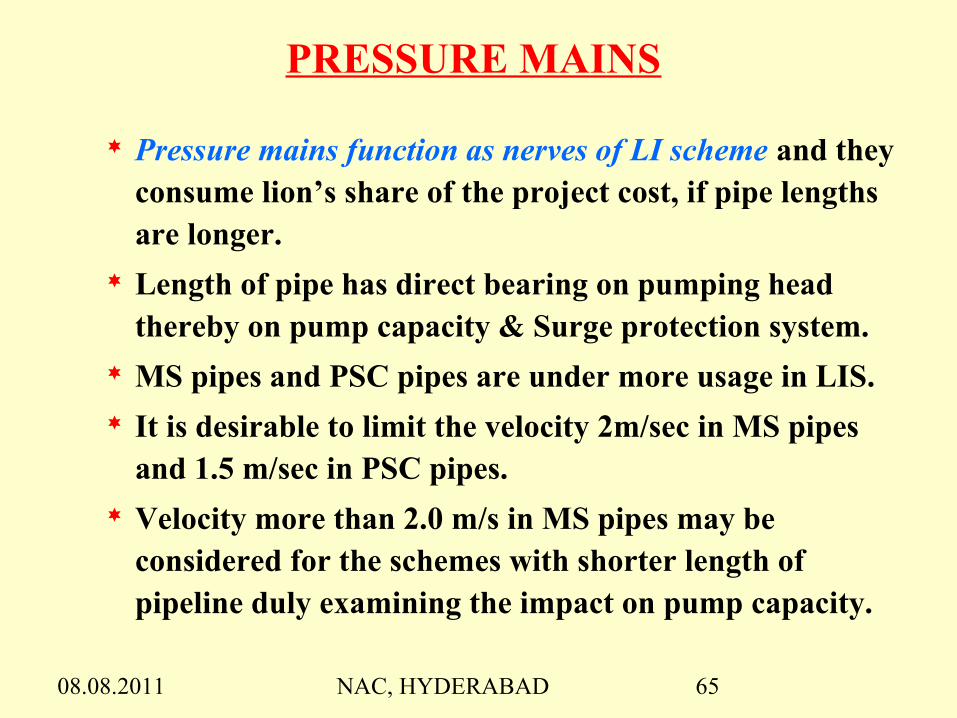
PRESSURE MAINS
Pressure mains function as nerves of LI scheme and they consume lion’s share of the project cost, if pipe lengths are longer.
Length of pipe has direct bearing on pumping head thereby on pump capacity & Surge protection system.
MS pipes and PSC pipes are under more usage in LIS. It is desirable to limit the velocity 2m/sec in MS pipes
and 1.5 m/sec in PSC pipes. Velocity more than 2.0 m/s in MS pipes may be
considered for the schemes with shorter length of pipeline duly examining the impact on pump capacity.
08.08.2011 NAC, HYDERABAD 66
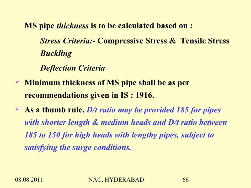
MS pipe thickness is to be calculated based on :
Stress Criteria:- Compressive Stress & Tensile Stress
Buckling
Deflection Criteria
Minimum thickness of MS pipe shall be as per
recommendations given in IS : 1916.
As a thumb rule, D/t ratio may be provided 185 for pipes
with shorter length & medium heads and D/t ratio between
185 to 150 for high heads with lengthy pipes, subject to
satisfying the surge conditions.

08.08.2011 NAC, HYDERABAD 67
Pipe Testing for Thickness
Radiography test
UV Test
Hydraulic Test
Hydraulic test may be 1.5 times design pressure as per codal
provisions and 1.25 times as per AWWA. For shorter length and
smaller heads, the hydraulic test may not be governing for pipe
thickness, however for lengthy pipes with high heads, it has
bearing on the scheme cost and hence shall be careful in adopting.
In GLIS, for 130 KM length with 135m head 14mm and 16mm
are provided for 2500 mm dia & 3000 mm dia respectively. If it is
TWICE, the pipe cost could be 25% more than actual cost.
08.08.2011 NAC, HYDERABAD 68
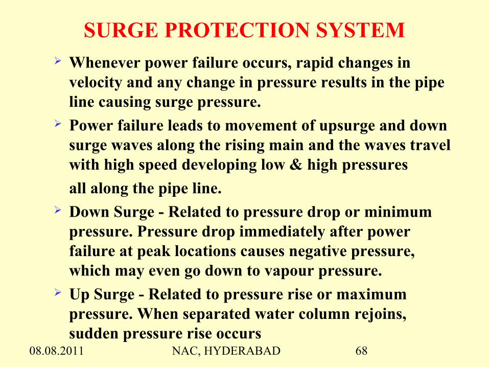
SURGE PROTECTION SYSTEM Whenever power failure occurs, rapid changes in
velocity and any change in pressure results in the pipe line causing surge pressure.
Power failure leads to movement of upsurge and down surge waves along the rising main and the waves travel with high speed developing low & high pressures
all along the pipe line. Down Surge - Related to pressure drop or minimum
pressure. Pressure drop immediately after power failure at peak locations causes negative pressure, which may even go down to vapour pressure.
Up Surge - Related to pressure rise or maximum pressure. When separated water column rejoins, sudden pressure rise occurs

08.08.2011 NAC, HYDERABAD 69
Surge analysis is a very complicated phenomenon and needs thorough analysis of the pipe line profile w.r.t surge heads to assess type and number of surge protection devices to be provided at appropriate locations.
Due attention shall be given to the surge analysis of pipe lines for schemes with high heads and lengthy pipes.
The surge generated can be controlled by providing combination of surge protection devices at various locations.

08.08.2011 NAC, HYDERABAD 70
Surge Protection Devices & Their Function Air Vessel - Controls upsurge and down
surge One way Surge tank - Controls down surge
directly and upsurge indirectly
Two way Surge tank- Controls both down surge and upsurge
ZVV & Surge relief valve - Controls upsurge Air valves / Air cushion Valves - Controls down
surge directly and upsurge indirectly Stand pipe - Controls down surge

08.08.2011 NAC, HYDERABAD 71

08.08.2011 NAC, HYDERABAD 72

08.08.2011 NAC, HYDERABAD 73
08.08.2011 NAC, HYDERABAD 74
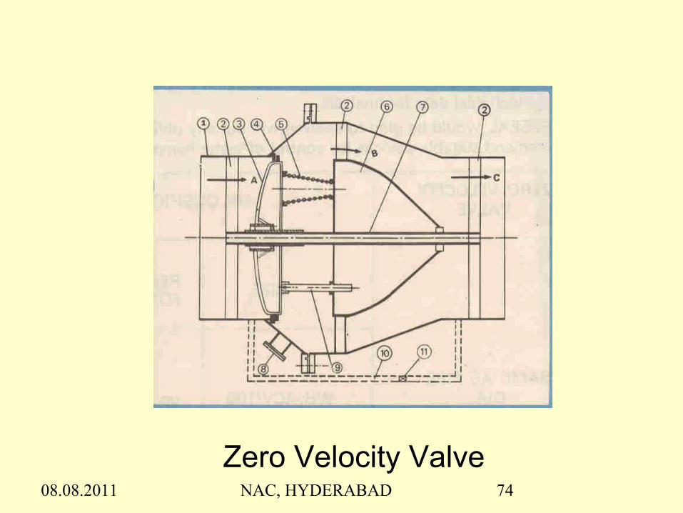
Zero Velocity Valve
08.08.2011 NAC, HYDERABAD 75
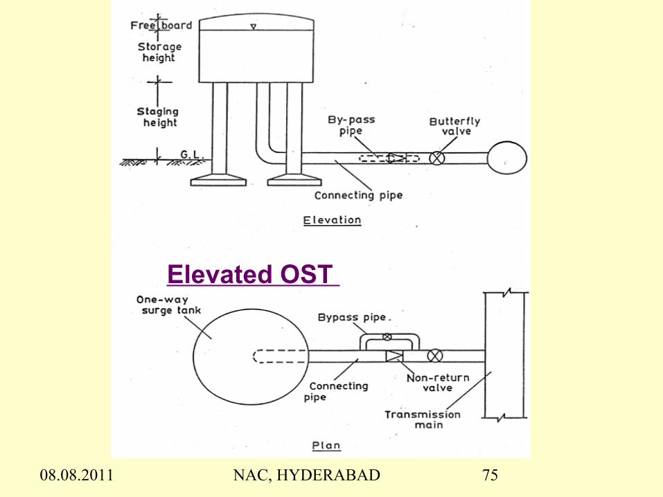
Elevated OST

08.08.2011 NAC, HYDERABAD 76
ONE WAY / TWO WAY SURGE TANKS

08.08.2011 NAC, HYDERABAD 77

08.08.2011 NAC, HYDERABAD 78
Water Hammer ConditionsSurge effect depends on topography / terrain, velocity and pipe
length and is predominant when frictional losses are more.
High Points in the pumping main alignment
Possibility of Water column separation in the main due to sudden power failure
Pipe line gradient is steeper than 1 : 20
Ratio of frictional loss to working head is less than 0.7
Presence of Check valve with slow closing arrangement
Velocity of normal flow exceed 1.0 m/s
08.08.2011 NAC, HYDERABAD 79
DELIVERY CISTERN
Delivery cistern is to be provided to dissipate the
energy of water falling freely from the pressure mains
and delivers into the canals.
Cistern shall be designed as vertical drop.
To have better energy dissipating arrangement, the bed
level of the cistern should always be kept below
the bed level of the leading canal.

08.08.2011 NAC, HYDERABAD 80
Delivery Cistern
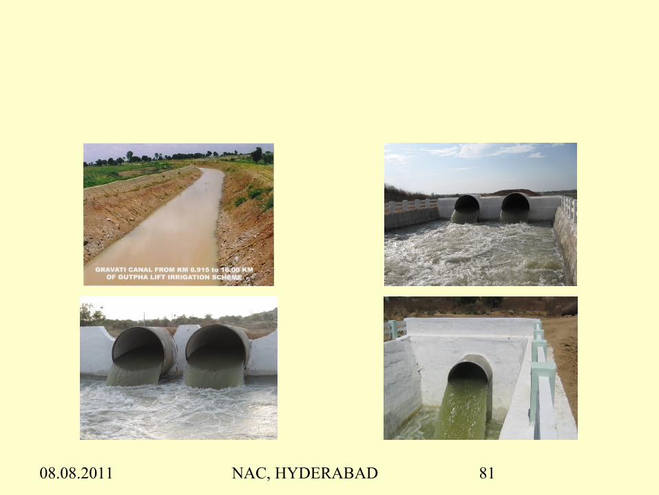
08.08.2011 NAC, HYDERABAD 81
08.08.2011 NAC, HYDERABAD 82
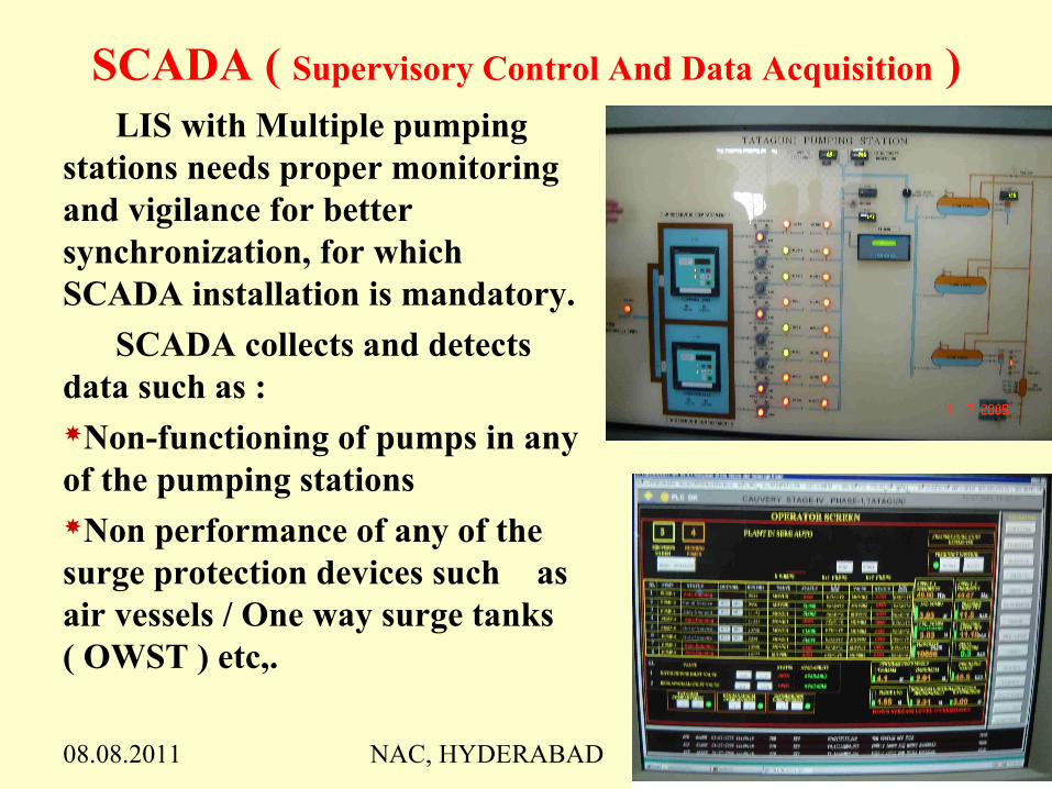
SCADA ( Supervisory Control And Data Acquisition )LIS with Multiple pumping
stations needs proper monitoring and vigilance for better synchronization, for which SCADA installation is mandatory.
SCADA collects and detects data such as :Non-functioning of pumps in any of the pumping stationsNon performance of any of the surge protection devices such as air vessels / One way surge tanks ( OWST ) etc,.

08.08.2011 NAC, HYDERABAD 83
SCADA Records data during operation of the scheme
Monitors inflow and outflow discharges of pumps
SCADA will be controlled at one station monitoring total alignment. Origin of failure of any component of the system enroute the alignment can be detected using SCADA, with the help of which operation of other pumping stations can be controlled.

08.08.2011 NAC, HYDERABAD 84
IMPORTANT ASPECTS IN DESIGN OF L.I.S.Influence of Velocity in Pressure main With increase in velocity of pipe, frictional loss increases
thereby increasing pump capacity along with pipe thickness due to pumping head as well as surge head
For every 0.50 m/s rise in Velocity of pipe, frictional loss rises by 75% to 100% with reduction of dia by 11% to 13% only.
Smaller dia is economical during initial stage of construction but power consumption will be high . Higher dia needs less power but with high initial cost.
Hence, it is desirable to allow higher velocities in shorter length of pipes and lower velocities in lengthy pipes ( particularly when the length of pipe is in KM ) owing to the recurring power consumption annually.

08.08.2011 NAC, HYDERABAD 85
Advantages of Minimum number of Rows More number of pipes with smaller dia leads to
more frictional losses as well as enhanced pumping heads /
pumping capacities and more quantity of steel.
More pipes with smaller dia causes more frictional losses
and initial cost as well as recurring power cost over lesser
no. of pipes with bigger dia with same velocity.
Further, more number of rows need more land acquisition
and CM & CD works.
Hence, it is desirable to provide bigger dia with less
number of rows of pipes, particularly for the schemes with
lengthy pressure mains.
08.08.2011 NAC, HYDERABAD 86
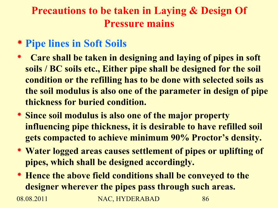
Precautions to be taken in Laying & Design Of Pressure mains
Pipe lines in Soft Soils Care shall be taken in designing and laying of pipes in soft
soils / BC soils etc., Either pipe shall be designed for the soil condition or the refilling has to be done with selected soils as the soil modulus is also one of the parameter in design of pipe thickness for buried condition.
Since soil modulus is also one of the major property influencing pipe thickness, it is desirable to have refilled soil gets compacted to achieve minimum 90% Proctor’s density.
Water logged areas causes settlement of pipes or uplifting of pipes, which shall be designed accordingly.
Hence the above field conditions shall be conveyed to the designer wherever the pipes pass through such areas.

08.08.2011 NAC, HYDERABAD 87
Clearance between Pipes
Clear distance between bigger dia pipes with more than two rows may be min of 5.0m for inspection :When multiple number of rows of pipes are laid and some of the pipes are only in operation, then empty pipes may create instability among the combined trench or when pipes are closely placed.Scour sluices / washouts with projections to flush out the water in pipes get overlapped when pipes are closely placed.It is desirable to have independent thrust blocks to avoid problems during O & M in the vicinity.

08.08.2011 NAC, HYDERABAD 88
If adequate clearance is not provided in water logged areas,
whenever any one of the pipe is empty, imbalance condition
develops which results in settlement or uplifting of pipe.
Handling of heavy / bigger dia pipes need crane for erection
& maintenance which needs 5.0 m ( min ) clearance in
between pipes
Whenever pipe is to be laid adjacent to the existing pipe in
operation, new pipe needs excavation and disturbs existing
pipe trench. Thus weakening the degree of compaction made
to already existing one and resulting imbalance of earth
pressure on existing pipe. If sufficient gap is provided, the
effect can be minimized.

08.08.2011 NAC, HYDERABAD 89
Connection of Pump delivery pipe and Pressure mains
When multiple number of rows of delivery pipes are required to
be connected to a pressure main, a manifold is required. In which
case, the design discharge may be increased by 2.5% for each pump to
account for system resistance losses in manifold.
Types of Manifolds
WYE type – May be useful when one or two delivery pipes need to be
connected to a single pressure main
Cylindrical – When rows of pressure mains is less than no. of pumps
Whenever stand by pump is provided, cylindrical manifold may be
mandatory ( twice the dia but not less than equivalent dia of pressure
mains) as rotation of stand by pump in wye junction is not possible to
satisfy equal discharge in pressure mains.

08.08.2011 NAC, HYDERABAD 90
CONCLUSIONS L.I. schemes are going to play major role in coming days and
due attention shall be given to the planning and design of LIS for better performance and efficiency of schemes.
Alignment shall be so chosen comprising shorter length of approach channel and shorter length of pressure mains. As far as possible, greater length of gravity canal shall be provided for economy in LIS.
Pumps function as heart of LIS and hence attention shall be given in fixing the duty point of the pump. For optimization of the scheme, duty point shall be with respect to level above LWL.
Pumping discharge shall be designed for mean average of crop water requirement wherever intermediate balancing reservoirs are present with pumping stations.
08.08.2011 NAC, HYDERABAD 91
Importance shall be given in design of sump dimensions and arrangement to avoid undesirable flow condition. Physical model studies shall be conducted for LIS and shall be mandatory for river intake lifts.
As the pressure mains act as nerves of LIS, care shall be taken for pipes to be laid in BC soils, water logged area and at crossing of vagus/drains.
Low velocity in pipes may be economical for the schemes with lengthy pressure mains, however higher velocity in pipes may be permitted for schemes with shorter length.
Larger dia with less number of rows may be economical with respect to installation cost as well as running cost.
Adequate clearance shall be maintained between pipes for stability as well as maintenance purpose.
Due attention shall be given to surge parameters which are vital aspects for proper functioning of the pipe line.
LI Scheme comprising multiple pump houses shall be provided with SCADA for observing & monitoring entire system.

08.08.2011 NAC, HYDERABAD 92
AYACUT DETAILS OF L.I.SCHEMES
PUSHKARA L.I.S. - 1,85,906 Ac TADIPUDI L.I.S. - 68,600 Ac RAJIV SAGAR L.I.S. - 4,00,000 Ac ALISAGAR L.I.S. - 53,793 Ac GUTPAH L.I.S. - 38,793 Ac RAJIV BHIMA L.I.S. - 2,03,000 Ac NETTAMPADU L.I.S - 2,00,000 Ac KALWAKURTHY L.I.S. - 3,40,000 Ac H.N.S.S. L.I.S. - 6,21,000 Ac

08.08.2011 NAC, HYDERABAD 93
POWER GENERATION IN A.P.
1 THERMAL 2973 MW
2 HYDRO 3586 MW
3 GAS 999 MW
3 BIO MASS 312 MW
4 WIND 98 MW
5 MINI HYDEL 91 MW
6 SHARE FROM CENTRAL SECTOR 2465 MW
7 OTHERS 182 MW
10706 MW

08.08.2011 NAC, HYDERABAD 94
POWER PLANTS NEARING COMPLETION
1 THERMAL 810 MW
2 HYDRO 474 MW
1284 MW
POWER PLANTS PROPOSED
1 THERMAL 7000 MW
2 OTHERS 2882 MW
9882 MW

08.08.2011 NAC, HYDERABAD 95
Thank You

08.08.2011 NAC, HYDERABAD 96
AMRP LIFT SCHEME(SLBC)

08.08.2011 NAC, HYDERABAD 97
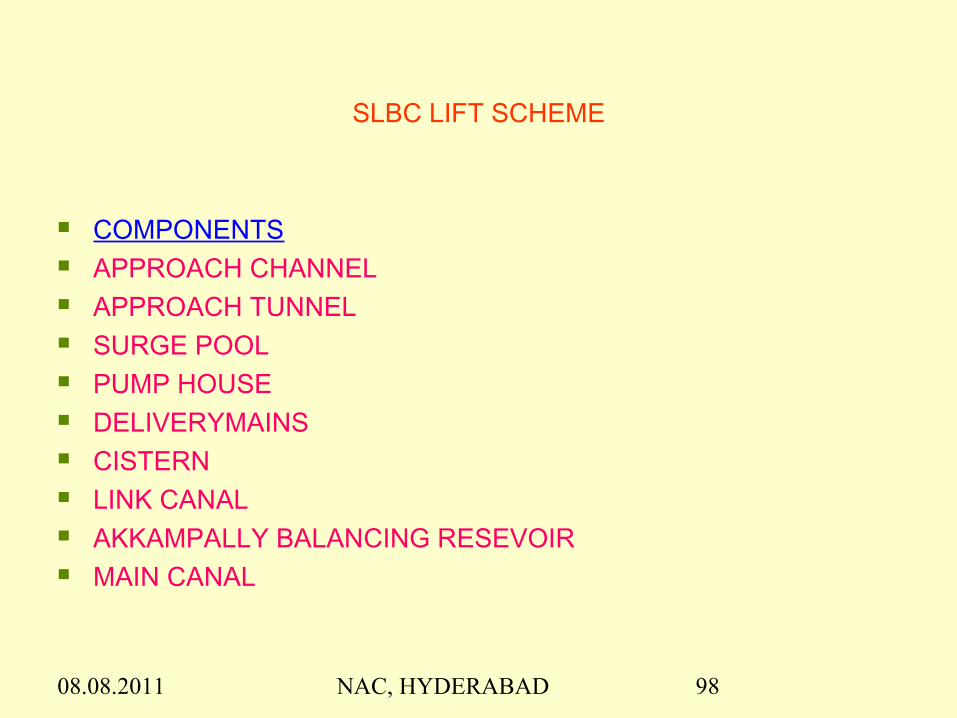
SLBC LIFT SCHEME
Aim : 1) To provide irrigation (ID) to 2.20 lakh acres
2) To provide drinking water to 516 villages
08.08.2011 NAC, HYDERABAD 98
SLBC LIFT SCHEME
COMPONENTS APPROACH CHANNEL APPROACH TUNNEL SURGE POOL PUMP HOUSE DELIVERYMAINS CISTERN LINK CANAL AKKAMPALLY BALANCING RESEVOIR MAIN CANAL
08.08.2011 NAC, HYDERABAD 99
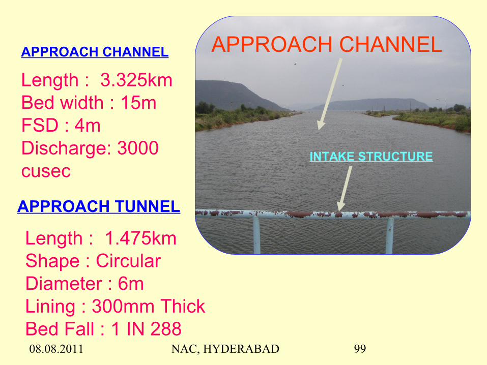
APPROACH CHANNELAPPROACH CHANNEL
Length : 3.325kmBed width : 15mFSD : 4mDischarge: 3000 cusec
APPROACH TUNNEL
Length : 1.475kmShape : CircularDiameter : 6mLining : 300mm ThickBed Fall : 1 IN 288
INTAKE STRUCTURE

08.08.2011 NAC, HYDERABAD 100
SURGEPOOL
Size : 20mX50mX62mBottom Level : +138.00mDraft Tube Gates : 2.60mX5.00mWeight of each gate : 8.07MT
08.08.2011 NAC, HYDERABAD 101
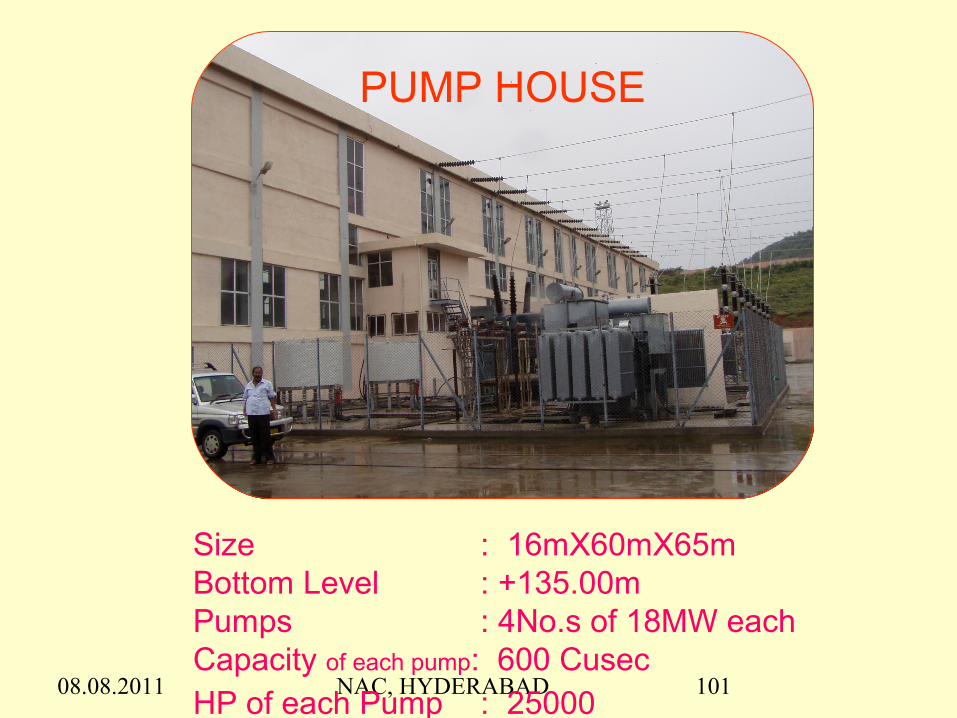
PUMP HOUSE
Size : 16mX60mX65mBottom Level : +135.00mPumps : 4No.s of 18MW eachCapacity of each pump: 600 CusecHP of each Pump : 25000

08.08.2011 NAC, HYDERABAD 102
SLBC LIFT SCHEME
COMPONENTS APPROACH CHANNEL APPROACH TUNNEL SURGE POOL PUMP HOUSE DELIVERYMAINS CISTERN LINK CANAL AKKAMPALLY BALANCING RESEVOIR MAIN CANAL

08.08.2011 NAC, HYDERABAD 103
DELIVERY MAINS
Size : 2.50m dia CircularLength : 655mNo. of rows : 4No.sSteel : IS 2002 Grade-IIIThickness of Plates : 14mm
& 16mm

08.08.2011 NAC, HYDERABAD 104
Cistern Reservoir Bund
Length of Dam : 2.290kmCapacity : 0.28TMCFRL : +247.00mTBL : +249.00m

08.08.2011 NAC, HYDERABAD 105
LINK CANAL
Length of Canal : 9.260 kmDischarge : 2400 CusecBed Width : 2.00 mFSD : 3.00 mBed fall : 1 in 7000

08.08.2011 NAC, HYDERABAD 106
A.M.R.P. Main Canal From Akkampally Balancing Reservoir
Surplus EscapeMain Canal Regulator

08.08.2011 NAC, HYDERABAD 107
H.Ps of Main CanalAt Km 25.000 (Common point)
Discharge: 65.258 Cumec
Bed Width: 19.10 m FSD : 3.10 m CBL @ starting: +230.100 m

08.08.2011 NAC, HYDERABAD 108
SALIENT FEATURES
MDDL : +155.45m Max. Elevation to be pumped :249.00m Maximum Static Head : 96m Minimum Static Head :69m Cost of the Scheme :Rs.1026 Crore Cost of Head works up to Cistern intake :Rs.300 Crore

08.08.2011 NAC, HYDERABAD 109
PUMPS
Type of Pump : Vertical shaft single stage Francis Type Runner
Normal speed : 428.60 RPM Rated Discharge : 16.85 Cumec (600 cusec) Guide vane centre l ine : +142.00m Submergence of GV
central l ine below min. water level : 11.00m Allowable frequency : 50.5Hz to 47.50Hz.

08.08.2011 NAC, HYDERABAD 110
DESIGN OF PUMPS
Capacity of Pump = 9.81XQxHX1.25 KW Efficiency
where Q= Discharge in cumec H= Dynamic Head in m
Capacity of Pump = 9.81X16.85x81X1.25 / 0.92 =18191KW or Say 18MW
These pumps function from 69m static head to 96m static headThe discharge varies with reference to variation in head and frequencyGuide vane opening is to be adjusted as per head and frequencyThough pumps are designed for 18MW , the input is about 15 MW only

08.08.2011 NAC, HYDERABAD 111
MOTORS
Type : Vertical shaft AC motor Speed : 428.60 RPM Power : 18 MW – 11 KV Frequency : 50 Hz Pf (leading) :0.95
08.08.2011 NAC, HYDERABAD 112
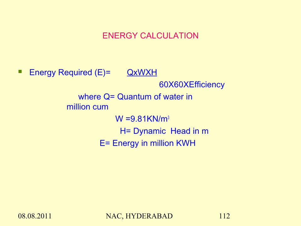
ENERGY CALCULATION
Energy Required (E)= QxWXH 60X60XEfficiency
where Q= Quantum of water in million cum
W =9.81KN/m3
H= Dynamic Head in m E= Energy in million KWH
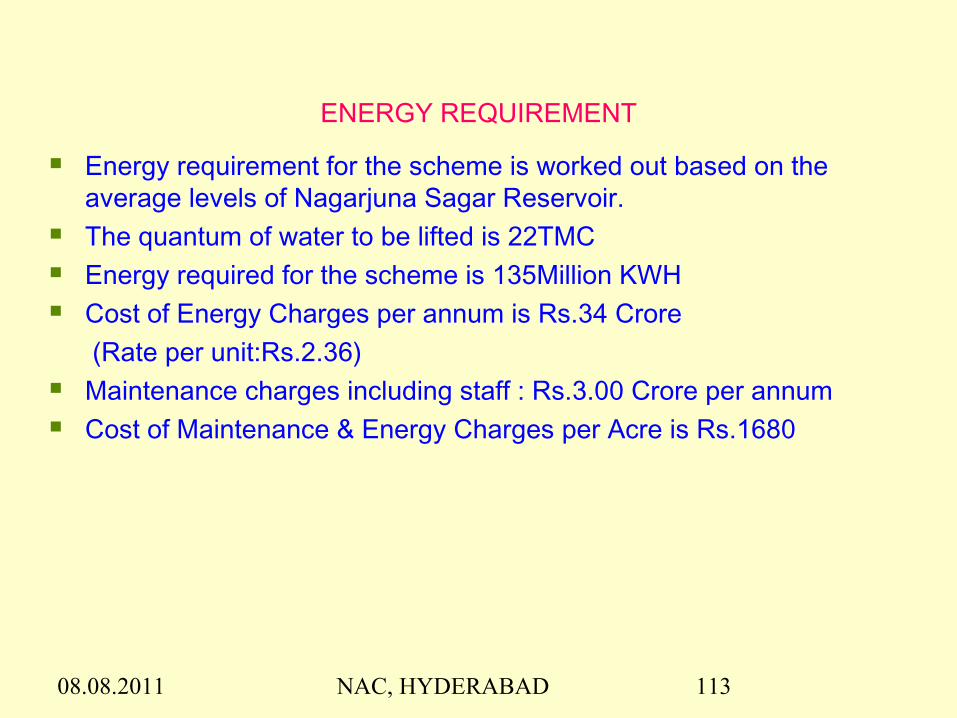
08.08.2011 NAC, HYDERABAD 113
ENERGY REQUIREMENT
Energy requirement for the scheme is worked out based on the average levels of Nagarjuna Sagar Reservoir.
The quantum of water to be lifted is 22TMC Energy required for the scheme is 135Million KWH Cost of Energy Charges per annum is Rs.34 Crore
(Rate per unit:Rs.2.36) Maintenance charges including staff : Rs.3.00 Crore per annum Cost of Maintenance & Energy Charges per Acre is Rs.1680

08.08.2011 NAC, HYDERABAD 114
Thank You