08. eh engine (1).pdf
TRANSCRIPT

8/10/2019 08. EH Engine (1).pdf
http://slidepdf.com/reader/full/08-eh-engine-1pdf 1/15
Page 1
Lotus Service Notes Section EH
ENGINE
SECTION EH
Sub-Section Page
General Description EH.1 3
Maintenance Operations EH.2 7
Engine Removal/Replacement EH.3 11
Special Tools EH.4 13
Engine Management Component Location EH.5 14
Elise S Supplement (1ZZ-FE) EH.6 15
See also Toyota engine repair manual B120T0327J and Toyota 2ZZ-GE engine
supplement C120T0327J

8/10/2019 08. EH Engine (1).pdf
http://slidepdf.com/reader/full/08-eh-engine-1pdf 2/15
Lotus Service Notes Section EH
Page 2
Engine Sections (2ZZ-GE)
From LH side From front
Cylinder head section
Exhaust side Intake side
e226
e227
8/10/2019 08. EH Engine (1).pdf
http://slidepdf.com/reader/full/08-eh-engine-1pdf 3/15
8/10/2019 08. EH Engine (1).pdf
http://slidepdf.com/reader/full/08-eh-engine-1pdf 4/15
Lotus Service Notes Section EH
Page 4
e223
e224
e222

8/10/2019 08. EH Engine (1).pdf
http://slidepdf.com/reader/full/08-eh-engine-1pdf 5/15
Page 5
Lotus Service Notes Section EH
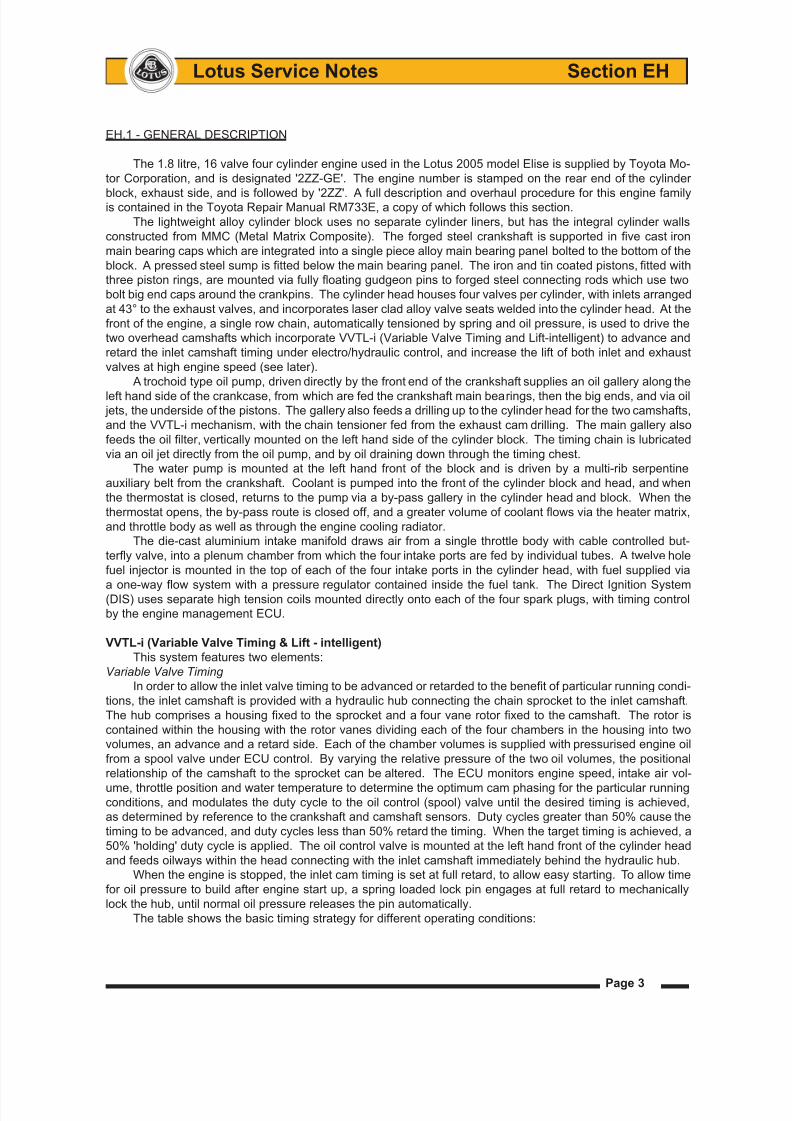
Note that compromises are involved in the programming of inlet cam timing, since advancing the valve
opening point also advances the valve closing point, when the ideal might be to advance the opening and retard
the closing points. For any particular engine running conditions, the timing is adjusted to optimise either the
valve opening point and overlap period, or the valve closing point, whichever provides the most benefit.
The range of inlet cam timing available is from:
Opening 33° BTDC, Closing 15° ABDC )
to; ) with standard (low speed) valve lift
Opening 10° ATDC, Closing 58° ABDC )
or;
Opening 58° BTDC, Closing 54° ABDC }
to; } with high speed valve lift (see below)
Opening 15° BTDC, Closing 97° ABDC }
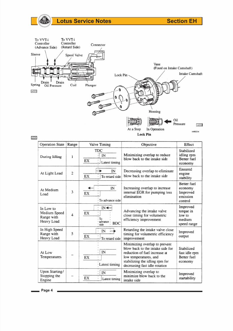
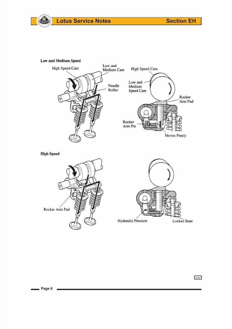
Variable Valve Lift
Both inlet and exhaust camshafts are machined with two cams for each cylinder, a low lift cam and a high
lift cam. Each low lift cam actuates, via a low friction roller, a rocker arm which connects with a pair of inlet or
exhaust valves. The corresponding high lift cam actuates a spring loaded tappet housed within the rocker arm,
and under low speed conditions, has no effect on valve operation due to the clearance between the bottom of
the tappet and the rocker arm.
When engine speed reaches 6,000 rpm at normal running temperature, the ECU operates a spool valve
on the back of the cylinder head to close an oil return line, and raise oil pressure within the rocker pivot shaft
and passages within each rocker. This increased oil pressure is sufficient to overcome the spring loading of a
packer pin contained within each rocker arm, which is then forced between the bottom of the high speed cam
tappet and the rocker arm. Each high lift cam then controls valve operation, with the rocker being lifted clear
of the low speed cam. The higher valve lift for both inlet and exhaust valves in conjunction with the variable
valve timing, provides greater efficiency and power output at high engine speeds.
Standard (low speed) valve lift: - inlet; 7.25 mm
- exhaust; 7.25 mm
High speed valve lift: - inlet; 11.4 mm
- exhaust; 10.0 mm
Note that engine speed is limited to 6,000 rpm until normal running temperature has been attained.
Illustrations overleaf...............................
8/10/2019 08. EH Engine (1).pdf
http://slidepdf.com/reader/full/08-eh-engine-1pdf 6/15
8/10/2019 08. EH Engine (1).pdf
http://slidepdf.com/reader/full/08-eh-engine-1pdf 7/15
Page 7
Lotus Service Notes Section EH
Overhaul Notes
1. Timing Marks
Take care when setting the engine to its 'timing' postion. Crankshaft at TDC, inlet cam pulley mark facing
inwards on centreline, exhaust cam pulley mark facing inwards but ONE TOOTH COUNTERCLOCKWISE
from centreline.
2. Valve Clearances
a) It is unlikely that valve clearances will require adjustment unless components are replaced. A single
forked rocker arm is used to operate a pair of valves, which are shimmed during manufacture for equal
clearance. Routine service clearance checks should be made between the cam and roller follower. Only
if a valve or rocker arm is replaced need the clearance between individual valves and the rocker arm be
measured. Adjustment procedure is detailed in the text.
b) When using the shim adjustment special tool, before removing a shim from a valve stem, ensure that
the oil drain passages on the exhaust side of the head are blocked with paper towel. Shims are easily
dropped and may fall down the drain passages into an oil gallery in the crankcase, requiring engine removal
to retrieve.
3. Stretch Bolts
The cylinder head bolts, big end bolts and main bearing cap bolts are 'stretch' type with an angular tight-
ening procedure. The bolts should be measured to determine their suitability for re-use. Measure length
or diameter as specified in the text. Note that the big end bolts are 8.7 to 8.8 mm standard diameter, with
8.5 mm minimum.
4. Timing Chain Tensioner
The maintenance free timing chain tensioner uses spring tension and engine oil pressure in conjunction
with a non-return ratchet mechanism to maintain chain tension. A pivotted hook on the tensioner body is
provided to aid assembly, by enaging with a pin on the spring plunger to hold the assembly retracted whilst
fitting. After fitment to the timing cover, the engine is then turned backwards so that the chain forces the
plunger into the tensioner body, which action pushes the hook into a disengaged position and allowing
tension to be applied on resumption of normal rotation. The ratchet mechanism prevents subsequent
plunger retraction.
5. Bearing Shell Size Coding
Note that the main bearing shells and big end shells are selective thickness dependent on journal and
housing size. Pistons are one size only. No reboring or crankshaft grinding is permitted.
Main bearing housing size codes are stamped onto the cylinder block, and crankshaft journal size codes
on the crank. If necessary, Plastigage can be used to deterime oil clearance. Big end codes are stamped
only on the connecting rod caps. Service replacement shells will also be marked on the back with the size
code.
6. Knock Sensor
The knock sensor used for Lotus applications is an annular type fitted over an M8 stud, with the retaining
nut tightened to 20 Nm.
EH.2 - MAINTENANCE OPERATIONS
Engine Oil Level Check
The engine oil level should be checked regularly, such as every two or three fuel stops, and the oil level
maintained near the top mark on the dipstick. It is especially important to keep a check on the oil level during
the vehicle’s first 1,000 miles (1,600 km), as both the fuel and oil consumption will be prone to some variance
until the engine components have bedded in.
The best time to check the level is when the oil is warm, such as during a fuel stop. Ensure that the car is
parked on a level surface and that a few minutes have elapsed since stopping the engine to allow oil to drain
back into the sump. If the engine is stopped before reaching normal running temperature, the oil will not drain
back so readily, and the dipstick will display an artificially low reading.

8/10/2019 08. EH Engine (1).pdf
http://slidepdf.com/reader/full/08-eh-engine-1pdf 8/15
Lotus Service Notes Section EH
Page 8
Dipstick: The dipstick is identifiable by its yellow loop handle, and is located at the right hand front of the engine.
Withdraw the dipstick, and wipe with a paper towel. Replace the dipstick, if necessary feeding the blade into
the tube with the fingers, before pressing firmly to ensure that the handle is fully seated. Withdraw the dipstick
again to inspect the oil level, which should lie between the two dimples on the end of the stick.
The oil level should be maintained at the
upper of these two marks in order to provide
optimum engine protection.
Topping Up: If topping up is necessary, un-
screw the oil filler cap from the left hand end of
the cam cover. Add a suitable quantity of the
recommended engine oil (see ‘Recommended
Lubricants’) taking care not to spill any oil onto
engine or electrical components; use a funnel
if necessary.
The difference between high and low
dipstick marks is equivalent to 1.5 litre. Allow
several minutes for the oil to drain through to
the sump before re-checking the oil level.
Do NOT overfill, or lubrication will be degraded and consumption increased as the oil becomes aerated.
Refit the filler cap, turning clockwise until secure.
Engine Oil Change
The use of high quality oil, renewed at the specified intervals, is the key to engine longevity and sustained
performance. Adhere strictly to the engine oil and filter change intervals specified in the Maintenance Sched-
ule.
For access to the engine sump and filter, the engine bay undertray must first be removed. This is most
easily achieved with the vehicle raised on a garage hydaulic lift, or alternatively, parked over an inspection pit.
The drain plug is located at the rear of the sump, and should be removed to drain the sump immediately after
a run when the oil is warm and the impurities are still held in suspension.
WARNING: - Take all suitable precautions to guard against scalding from the hot oil.
Allow the oil to drain completely before cleaning the drain plug, fitting a new sealing washer, and tighten-
ing securely. Refill with the recommended lubricant via the oil filler on the camshaft cover, to the top mark on
the dipstick, allowing several minutes for the oil to drain through to the sump before checking the level. Take
care not to overfill. Refit the oil filler cap securely, and check the oil level again when the engine is fully warm
(see above).
Oil Filter
The canister type oil filter is vertically
mounted at the front of the engine, and is
accessible from beneath after removal of the
engine bay undershield. The filter should be
renewed along with the engine oil, at intervals
specified in the Maintenance Schedule.
WARNING: Take all suitable precautions to
guard against scalding from the hot oil.
Remove the filter by turning in a coun-
terclockwise direction, if necessary using an
oil filter wrench, and dispose of safely.
Ensure that only a Lotus specified filter is fitted, as parts with identical outward appearance can contain
different internal features. Before fitting a new filter, clean the mating face on the engine, and smear the new
seal on the filter with clean oil. Add a small amount of clean engine oil into the filter, screw onto its spigot and
tighten BY HAND sufficiently to make a secure seal, typically 2/3 to 3/4 of a turn after the sealing faces have
made contact. Overtightening using a filter wrench may damage the canister and/or complicate subsequent
OIL FILTER
(Viewed
from
beneath)
OIL FILLER CAP ohs131
DIPSTICK ohs132

8/10/2019 08. EH Engine (1).pdf
http://slidepdf.com/reader/full/08-eh-engine-1pdf 9/15
Page 9
Lotus Service Notes Section EH
removal. Start the engine and check for oil leaks. Re-check the security of the filter, further tightening by hand
if necessary. Check the oil level (see above) when the engine is fully warm.
Oil Coolers
The foregoing oil change procedure does not disturb the oil quantity contained in the twin oil coolers and
associated pipework, but is considered perfectly satisfactory for routine maintenance operations. In instances
of major engine failure where the oil system may be contaminated with metallic debris, all oil cooler l ines should
be thoroughly flushed out and the oil cooler radiators replaced.
If the oil cooler circuit is drained or replaced, the following procedure should be adopted to fill the cooler
system before starting the engine:
1. Attach a tube to the bleed nipple on the sandwich plate between oil filter and engine block, and lead into
a catch tank. Open the bleed nipple.
2. Disconnect the outlet hose from the top of the LH oil cooler, and pour engine oil into the cooler until oil
reaches the bleed nipple (approx. 2.5 litres). Close the bleed nipple, tightening to 8 Nm.
3. Connect the LH cooler outlet hose and tighten to 40 Nm.
4. Add a further 0.7 litres of oil into the engine to accommodate the volume of the return hose between LH
oil cooler and engine.
5. After starting the engine, restrict running to idle speed for a minimum of 5 minutes, to allow the oil cooler
lines to be purged of air. Stop engine and re-check oil level.
Note: For cars fitted with an Accusump pressurised oil storage canister, refer to separate literature.
Oil cooler feed hose
Oil cooler return hose
Sandwich plate
bleed nipple
Oil filter canister
e228

8/10/2019 08. EH Engine (1).pdf
http://slidepdf.com/reader/full/08-eh-engine-1pdf 10/15
Lotus Service Notes Section EH
Page 10
Air Cleaner Element
The air filter should be inspected at intervals dependent on the operating conditions. When the vehicle is
operated in a relatively clean environment, the element should be renewed at intervals specified in the Main-
tenance Schedule, but where a dusty or smog laden atmosphere prevails, or other factors contribute to filter
contamination, more frequent replacement will be required dependent on the level of pollution.
A disposable folded paper type air
cleaner element is fitted in a housing at the
left hand front of the engine bay. For access
to the element, the left hand rear wheel and
wheelarch liner must first be removed. Before
opening the air cleaner housing, the wheelarch
area should be cleaned to reduce the possibil-
ity of filter or housing contamination with road
dirt.
To open the filter housing, release the
two spring clips at the outboard end of the
housing, and hinge open sufficiently to allow
the element to be withdrawn.
Clean the inside of the housing, including the joint faces, taking care not to contaminate the ‘clean’ engine
side of the assembly. Fit the new filter element into position with the shallow side facing the 'clean', engine
side of the housing. Ensure that the hinge lugs at the inboard end of the housing are correctly engaged before
closing the housing and securing with the two spring clips. Refit the wheelarch liner and rear wheel.
Auxiliary Drive Belt
A single multi-rib serpentine type belt is used to transmit drive from the crankshaft to the water pump,
alternator and a.c. compressor, with a slave pulley fitted in place of the power steering pump used in other
applications. A hydraulically damped, spring loaded tensioner arm applies tension to the back of the belt, and
is maintenance free. The belt itself should be inspected for condition at each service interval, and if it exhibits
any evidence of physical damage, cracking, fraying, perishing, abrasion or contamination, it should be replaced.
In the case of oil or coolant contamination, the cause must be identified and rectified, and each of the pulleys
must be thoroughly degreased before the new belt is fitted.
For further details, refer to section CH in the Engine Repair Manual, but note that only a six-sided socket
should be used on the cast boss on the tensioner arm. Due to the manufacturing draft angle of the casting, a
twelve point socket is liable to cause damage.
Spark Plugs
The ignition system uses a distributorless ignition system (DIS) which employs an individual high tension
coil for each of the four spark plugs. Each coil is mounted directly onto its spark plug using an integral connector
and is secured to the cam cover with a single screw. The spark plugs use small diameter centre electrodes made
of iridium for long life and high performance, and require changing only at 54,000 mile (90,000 km) intervals.
For further details, refer to section IG in the Engine Repair Manual.
AIR CLEANER
ELEMENT
ohs146

8/10/2019 08. EH Engine (1).pdf
http://slidepdf.com/reader/full/08-eh-engine-1pdf 11/15
Page 11
Lotus Service Notes Section EH
EH.3 - ENGINE REMOVAL/REPLACEMENT
It is recommended to remove the rear clamshell prior to powertrain removal in order to improve access,
and to reduce the possibility of paint damage. The engine may be removed from above, with or without the
transmission. The following procedure applies to the engine/transmission assembly, but to avoid disturbing
the suspension, refer to sub-section FJ.5 to separate the engine from the transmission before withdrawing the
engine alone.
Fuel Pressure Relief Procedure
This procedure should be used prior to disconnecting any part of the fuel line.
- Pull out the fuel pump fuse (on the left
hand side of the engine bay bulkhead, as
shown), start the engine, and run until it
stops from starvation. Crank the engine
for a further few seconds.
- If the engine is a non-runner, pull out the
fuel pump fuse, and crank the engine
for 20 seconds to minimise residual fuel
pressure.
- Disconnect the battery.
It is recommended first to release the
quick fit connector located to the rear of
the coolant header tank:
- Release the retaining clip securing the
pipe joint to the header tank bracket.
- Slide the orange coloured safety lock to
allow access to the connector release
buttons.
- Surround the pipe joint with a shop towel
to absorb fuel contained in the pipework
before pressing the release buttons and
separating the joint.
WARNING: Be aware of the possibility of full pressure retention in the fuel line caused by a system
fault.
- Before re-making the joint, ensure that the or-
ange safety lock is fitted onto the pipe connector
in the orientation shown in the illustration.
- Push the male pipe end fully into the female
connector until a click is heard. Pull on the pipe
to ensure complete engagement.
- Slide the orange safety lock over the connector
to prevent accidental pressing of the release
buttons.
- Secure the pipe/connector using the pipe clip
on the header tank bracket.
Fuel pump
fuse (20A)
ohs136
Fuel pipe to
Orange engine
safety lock
Fuel pipe
from tank
Release
button
L64

8/10/2019 08. EH Engine (1).pdf
http://slidepdf.com/reader/full/08-eh-engine-1pdf 12/15
Lotus Service Notes Section EH
Page 12
1. Remove the engine bay undertray and diffuser, both rear road wheels and the rear clamshell (see sub-
section BR.7).
2. On a.c. cars, recover refrigerant and disconnect both a.c. hoses from the pipes at the rear of the RH
sill.
From beneath the car:
3. Drain coolant, transmission oil and, if necessary, engine oil. Diconnect the coolant inlet hose from the
thermosat housing and cap both apertures. Disconnect the two oil cooler hoses from the sandwich plate
and cap all ports and hoses.
4. Disconnect the exhaust manifold from the downpipe.
5. Release the gear cable routing clips from beneath the engine. Disconnect the earth braid between chas-
sis and transmission.
6. Release the clutch slave cylinder from the transmission housing and support aside.
7. Release the steady mounting between the front of the engine and the chassis, and between the rear of
the engine and the subframe.
From above:
8. Release the gearchange cables from the transmission by removing the 'R' clips retaining the inner cable
eyes, and the 'C' clips retaining the outer cables.
9. Disconnect the air intake hose between air cleaner and intake plenum, and release the brake servo vacuum
hose from the intake plenum.
10. Disconnect the throttle cable. Disconnect the radiator feed hose and heater feed hose from the rear end of
the cylinder head. Disconnect the heater return hose from the water rail, and the two hoses and electrical
connector from the header tank. Disconnect the re-circ. pump hose to the chassis pipe, and release the
electrical connector. Unplug the engine harness. Release the header tank bracket from the subframe,
and remove the bracket complete with tank and recirc. pump. Release the purge pipe from the throttle
body.
11. Remove the LH driveshaft from the transmission:
Release the top ball joint plinth from the LH hub carrier noting and retaining the camber adjustment shims,
and separate the toe-link ball joint separated from the carrier. The driveshaft inboard joint is retained in
the transmission by a round section circlip. The joint may be removed by applying a shock pull to the C.V.
joint body using a slide hammer with a forked end. Take great care not to damage the output oil seal on
withdrawal.
CAUTION: Do NOT attempt to remove the inboard C.V. joint from the transmission by pulling on the
driveshaft. The balls of the inboard joint are restrained for transit purposes only, by a circlip at the end
of the ball tracks. Applying an extension force to the joint will damage the balls and require joint replace-
ment. Apply pressure only to the outer body of the joint. Do not allow the brake hose to be stetched or
stressed, and support the driveshaft after withdrawal to protect the shaft joints and hub carrier. Cap the
driveshaft aperture in the transmission.
12. Remove the RH driveshaft from the transmission:
Release the top ball joint plinth from the RH hub carrier noting and retaining the camber adjustment shims,
and separate the toe-link ball joint separated from the carrier. The right hand driveshaft incorporates
a bearing for the extension shaft and it is this which retains the shaft in the transmission. Remove the
two bolts ecuring the bearing bracket, and withdraw the complete shaft assembly taking great care not
to damage the ouput oil seal. Do not allow the brake hose to be stetched or stressed, and support the
driveshaft after withdrawal to protect the shaft joints and hub carrier. Cap the driveshaft aperture in the
transmission.

8/10/2019 08. EH Engine (1).pdf
http://slidepdf.com/reader/full/08-eh-engine-1pdf 13/15
Page 13
Lotus Service Notes Section EH
13. Fit two engine lifting brackets T000T1437S to the left hand front and right hand rear of the cylinder head.
Sling support the power unit before releasing the RH and LH engine mounting brackets.
17. Carefully hoist the power unit from the car, whilst monitoring for any remaining connections.
Refit the unit in reverse order to removal with the following notes:
- Before re-fitting a driveshaft, first renew the round section circlip on the end of the left hand inboard joint
spigot shaft, and lubricate the circlip with grease. Also, check the condition of the transmission output seal,
and renew if necessary. Lubricate the lip of the seal with transmission oil, and grease the corresponding
shoulder on the driveshaft (C.V. joint) spigot, to reduce the danger of damaging the seal on assembly.
- Carefully insert the driveshaft into the transmission, with, on the left hand shaft, the two ends of the circlip
positioned lowermost, and rotate the shaft if necessary to engage the splines. Press the inboard joint outer
until a click indicates the engagement of the retaining circlip, if necessary using a brass drift and hammer.
Pull on the body to ensure its security. On the right hand shaft, fit the bolts securing the extension shaft
bearing to the engine mounted bracket, and torque to 64 Nm.
- Refer to section DH for rear suspension assembly details.
- For coolant refilling procedure, refer to section KH.
- For transmission details and gear cable adjustment, refer to section FJ.
EH.4 - SPECIAL TOOLS
The following engine special tools are available under Lotus part number:
Engine Lift Bracket T000T1437S 2 off
Bolt, engine lift bracket T000T1440S 2 off
Oil Filter Wrench T000T1441F 1 off
Valve Clearance Adjuster Set T000T1442F 1 off
Crankshaft Pulley Holding Tool T000T1443F 1 off
Flange Holding Tool T000T1444F 1 off
Engine lifting brackets
e229

8/10/2019 08. EH Engine (1).pdf
http://slidepdf.com/reader/full/08-eh-engine-1pdf 14/15
Lotus Service Notes Section EH
Page 14
EH.5 - ENGINE MANAGEMENT COMPONENT LOCATION
Key to engine management component location drawing
1. Electronic Control Unit (ECU).
2. Multi-function relay unit.
3. Oil control valve for variable valve lift.
4. Camshaft position sensor.
5. Fuel injector.
6. Knock sensor.
7. Oil control valve for variable valve timing.
8. Crankshaft position sensor.
9. Plug top coil.
10. Coolant temperature sensor.
11. Pre-catalyst oxygen sensor.
12. Post-catalyst oxygen sensor.
13. Oil pressure switch.
14. Throttle position sensor.
15. Vacuum solenoid for intake flap valve.
16. Mass airflow sensor.
17. Idle Air Control (IAC) valve (prior '06 M.Y.)
For component replacement procedures, refer to manual B120T0327J. For diagnostic codes, refer to Section
EMP.
1
24
3 5
6
17
7
16
8
15
9
14
13 10
12 11

8/10/2019 08. EH Engine (1).pdf
http://slidepdf.com/reader/full/08-eh-engine-1pdf 15/15
Page 15
Lotus Service Notes Section EH
EH.6 - ELISE S SUPPLEMENT
The Elise S, introduced in May 2006 uses the Toyota '1ZZ-FE' engine instead of the '2ZZ-GE' fitted in the
Elise 111R. The two engines are similar in basic architecture, with the 2ZZ having been derived from the 1ZZ,
and whilst the overhaul procedures are largely common, many of the principal components are different. This
section identifies the main differences between the two engine types.
Valve Mechanism
The 1ZZ uses the same VVT-i 'intelligent' variable intake valve timing system as used on 2ZZ, but without
the intake and exhaust variable valve lift feature. Valve clearance adjustment via selective cam followers rather
than 'top hat' shims. Airbox flap valve programmed to open at 5,000 rpm. Lower rpm limits (see below).
Dimensions
The bore and stroke differ between the two engines, although the capacity difference favours the 2ZZ by
only 2cc. The 1ZZ is more undersquare with dimensions of 79.0 x 91.5mm producing 1794cc (2ZZ: 82.0 x 85.0
= 1796cc). The angle between intake and exhaust valves on the 1ZZ is 10° less at 33°, to permit a compact
cylinder head without the requirement to accommodate variable valve lift. The compression ratio is dropped
from 11.5 to 10.0:1.
Cylinder Block
The open deck alloy cylinder block of the 1ZZ uses dry, thin wall, non-replaceable, cast iron cylinder liners
(2ZZ uses integrated MMC cylinder walls).
Manifolds
The inlet manifold is moulded in plastic to reduce weight and heat transference, and incorporates a resona-
tor feature to optimise gas pulsations for mid-range performance. A unique adaptor is used to link the manifold
to the electronic throttle body which differs from the 2ZZ and other 1ZZ types.
The simplified exhaust manifold and downpipe dispense with the divider plate used on the 2ZZ.
Cooling System
The cooling system is largely unchanged, with all 1ZZ cars using the oil/water heat exchanger and no
front mounted oil coolers. The throttle body is heated as previously, although the feed and return connections
differ in detail and no in-line throttle body thermostat is used.
Technical Data
1ZZ-FE 2ZZ-GE (reference)
Capacity 1794 cc 1796 cc
Bore 79.0 mm 82.0 mm
Stroke 91.5 mm 85.0 mm
Valve control VVT-i VVTL-i
Compression ratio 10.0:1 11.5:1
Compression pressure (250 rpm, normal run temp.) - new 1500 kPa (218 psi) 1400 kPa (203 psi)
- min. 1000 kPa (145 psi) 1000 kPa (145 psi)
Spark plugs - type NGK BKR5EYA-11 NGK IFR6A-11
Denso K16R-U11
- gap 1.0 ± 0.05mm 1.1 mm
Peak power (1999/99/EC) 100 kW (136 PS) 141 kW (192 PS)
@ 6,200 rpm @ 7,800 rpm
Peak torque (1999/99/EC) 172 Nm 181 Nm
@ 4,200 rpm @ 6,800 rpm
Maximum continuous engine speed 6,800 rpm 8,000 rpm
Maximum transient engine speed 7,150 rpm 8,500 rpm
Exhaust emissions (Euro 4 & LEV 1) - CO 0.23 g/km 0.42 g/km
- HC 0.050 g/km 0.078 g/km
- NOx 0.0217 g/km 0.0121 g/km
- HC + NOx 0.0717 g/km 0.07921 g/km - CO2 (combined) 196 g/km 208 g/km