0710_gearsolutions.pdf
DESCRIPTION
Gear Solution Magazine.TRANSCRIPT

Analyzing Bearing
Failure
Insights Into Ultrasonic
Cleaning
Site Safety tooth tipS
Company profile: Surface Combustion, Inc.
JULy 2010
Q&a: TraCe HillLoudon Industries, Inc.
In CollaboratIon wIth


JULY 2010 3
featuresBy Nicholas Bugliarello, Biji George, Don
Giessel, Dan McCurdy, Ron Perkins,
Steve Richardson, and Craig Zimmerman
Different heat treating processes
impart particular qualities
in your gears. In this article
Bodycote provides an in-depth
understanding of the available
options.
Heat Treat Processes for Gears
38
Analyzing Bearing FailureBy Steven Katz
No one wants to experience bearing
failure, but close study of all the factors
involved will allow you to help avoid
the associated costs and downtime in
the future.
24Company Profile: Surface Combustion, Inc.By Russ Willcutt
Founded on the basis of a proprietary
technology, this company has
continued to lead the way in
developing cutting-edge thermal
processes and equipment.
34Insights Into Ultrasonic CleaningBy Ed Sullivan
As is the case with any
manufacturing process, choosing
the right ultrasonic cleaning method
can mean the difference between
wasting time and making money.
26

JULY 2010 5
Departments
Gear Solutions (ISSN 1933 - 7507) is published monthly by Media Solutions, Inc., 266D Yeager Parkway Pelham, AL 35124. Phone (205) 380-1573 Fax (205) 380-1580 International subscrip-tion rates: $72.00 per year. Periodicals Postage Paid at Pelham AL and at addi-tional mailing offices. Printed in the USA. POSTMASTER: Send address changes to Gear Solutions magazine, P.O. Box 1210 Pelham AL 35124. Publications mail agreement No. 41395015 return undeliv-erable Canadian addresses to P.O. Box 503 RPO West Beaver Creek Richmond Hill, ON L4B4R6. Copyright®© 2006 by Media Solutions, Inc. All rights reserved.
No part of this publication may be repro-duced or transmitted in any form or by any means, electronic or mechanical, includ-ing photocopy, recording, or any informa-tion storage-and-retrieval system without permission in writing from the publisher. The views expressed by those not on the staff on Gear Solutions magazine, or who are not specifically employed by Media Solutions, Inc., are purely their own. All "Industry News" material has either been submitted by the subject company or pulled directly from their corporate web site, which is assumed to be cleared for release. Comments and submissions are welcome, and can be submitted to [email protected].
8Trends, data, and developments to keep you aware of what’s happening with your colleagues in the gear-manufacturing industry around the
country and world.
Industry News
53News of products, equipment, and resources from across the manufacturing spectrum that will help propel your company toward success.
Product Showcase
Trace Hill, president
Loudon Industries, Inc. 64Q&A
20One key to implementing a successful safety program is to make sure that it’s as convenient as possible for everyone involved, including those who enforce it.
Site SafetyTerry McDonald
22What is the true definition of “surface finish,” and how can the extremes of roughness be minimized? A deeper understanding will help overcome challenges.
Tooth TipsWilliam Crosher
57MACHINES
60MARKETPLACE
63ADVERTISER
INDEX
American Gear ManufacturersAssociation
In this section the premier supporter of gear manufacturing in the United States and beyond shares news of the organization’s activities, upcoming educational and training opportunities, technical meetings and seminars, standards development, and the actions of AGMA councils and committees.
Letter ................................................................................................. 15Calendar of Events .......................................................................... 16-17Association News ............................................................................ 16-17News (cont.)/Masthead ......................................................................... 18
Resources
JUly 2010 | VolUme 8 / no. 88
There’s a lot to be said for real-world, hands-on experience, especially in manufac-turing. It’s critical to any employee’s professional development, in fact. But there is also a strong argument to be made for developing relationships with academia, which can result in mutually beneficial research and allows a company to stay plugged into the latest technologies and methodologies being taught in college labs and classrooms. Surface Combustion, Inc., realizes the importance of this connection and has identified a number of ways in which to capitalize on it. One involves the aforementioned R&D, and another is an “engineer in training” program in which recent university graduates enter into an intense training period, learning their job from the ground up while also providing the company with fresh perspec-tives. We believe you’ll enjoy learning more about this innovative company in this issue’s profile.
As for our features, Bodycote has provided a team of experts—Nicholas Bugliarello, Biji George, Don Giessel, Dan McCurdy, Ron Perkins, Steve Richardson, and Craig Zimmerman—to address “Heat Treat Processes for Gears.” This is an in-depth and informative article that describes various types of heat-treat technolo-gies so that you’ll be positioned to choose the right approach for your particular application. We are also pleased to continue our longtime collaboration with ASM International's Heat Treating Society, producer of the HTPro eNews online publica-tion (visit www.asminternational.org to subscibe). Steven Katz of Emerson Bearing shares his thoughts on “Analyzing Bearing Failure,” pointing out that understand-ing all the factors involved can help you to avoid unnecessary downtime, and Ed Sullivan provides “Insights Into Ultrasonic Cleaning” that will help you save both time and money at the end of the manufacturing process. In his “Site Safety” column, Terry McDonald ponders ways to simplify safety-related procedures in your production facility—understanding that the easier you make something to accomplish, the more likely people are to get onboard—and William Crosher pro-vides us with a true definition of “surface finish” and how extremes of roughness can be minimized. Trace Hill, president of Loudon Industries, tells the story of how his company came into being, and how solid, longstanding relationships with his customers and vendors alike have helped the company weather the most recent economic downturn—and others before. We all realize the importance of these relationships, of course, but it’s a good thing to be reminded of occasionally.
In closing, we’d like to congratulate the AGMA on the success of its recent Strategic Resources Network (SRN) event held at GE Transportation’s headquar-ters in Erie, Pennsylvania, reported in this issue by Web Communications Manager Mary Ellen Doran. The 50-plus attendees toured the facilities and enjoyed a host of expert speakers: including Ed Hall, Sr., who is general manager of mechani-cal technologies; Bill Hali, senior product manager of GE Off Highway Product Management; Suraj Devadiga, product manager of Wind Gearboxes; and Steve Gerbracht, who is manager of GE Locomotive Systems. Suren Rao—managing director of the Gear Research Institute (GRI) at the Pennsylvania State University—also addressed the gathering, along with Jim Kane of Elwood Quality Steels. The AGMA is already planning upcoming events, which you can read about in upcoming issues of Gear Solutions magazine.
Russ Willcutt, editorGear Solutions [email protected]
(800) 366-2185
6 gearsolutions.com
Published by Media solutions, inc.P. O. BOx 1987 • Pelham, al 35124
(800) 366-2185 • (800) 380-1580 fax
Contributing writersNichOlas BugliarellO
William P. crOsherBiji geOrgeDON giessel
DaN mccurDyTerry mcDONalD
rON PerkiNssTeve richarDsONcraig ZimmermaN
sTeveN kaTZeD sullivaN
David C. CooperPuBlisher
Chad MorrisonassOciaTe PuBlisher
EDITORLetterFrom tHe
Dav id C . C o operPresiDeNT
C had Mor r i s on vice PresiDeNT
Ter e sa C o operOPeraTiONs
eDitoriALRuss Willcutt
eDiTOr
Kassie HugheyassisTaNT
sALesBrad Whisenant
NaTiONal sales maNager
CirCuLAtionTeresa Cooper
maNager
Jamie WillettassisTaNT
Kassie HugheyassisTaNT
ArtJeremy AllenarT DirecTOr
Michele HallgraPhic DesigNer


8 gearsolutions.com
okuma Tech Center and Hartwig Host Sme Chapter
The Houston chapter of the Society for Manufacturing Engineering (SME) held their monthly meeting and enjoyed a facility tour last May at the Okuma Tech Center. SME members and guests attended a presentation by Hartwig, Inc. Team leader Gary Frick and Bryan Newman, THINC product specialist, gave a presentation on the THINC control, illustrating its open architecture and plug-and-work capabilities. Attendees were given the opportunity to see the Okuma machines in action.
Machine demonstrations included the VTM-80Yb, five-axis vertical lathe with “M” tool functions, the Multus B400-W multi-function mill/turn machine and an MU-400 VA 5-axis trunion-style machining center. The highlight of the evening was the automated Okuma oil-coupling cell, which produces API couplings for oil patch and runs with minimal operator intervention.
On hand were representatives from members of Partners in THINC who answered questions from attendees and presented product demonstrations on workholding, industrial lubricants, tooling, and gauging. Bob Waters, tech center coordinator, observed that many of the guests were first-time visitors to the center and that they were exceptionally engaged and took the time to speak with and ask ques-tions of the engineers and operators. SME Member Ed Gordon stated, “It was a most enjoyable learning occasion. Okuma has turned the ‘partnership’ concept into what appears to be a very effective organiza-tion of resources capable of beneficially resolving any customer’s problem or need.”
Okuma America Corporation is the U.S.-based affiliate of Okuma Corporation, a world leader in the development of computer numeric controls (CNC) and machining technology founded in 1898 in Nagoya, Japan. Learn more at [www.okuma.com]. For half a century Hartwig has been focused on helping its customers control their manufacturing destiny and keeping manufacturing in the United States. One of
Companies wishing to submit materials for inclusion in Industry News or Product Showcase should contact Editor Russ Willcutt at [email protected]. Releases accompanied by color images will be given first consideration and are required for Product Showcase.
Trends, Data, and Industry Developments
the largest machine tool and metal cutting distributors in North America, Hartwig owns and operates eight office locations covering 14 states. Visit online at [www.hartwiginc.com].
Solar atmospheres launches new Web SiteOver the past year Solar Atmospheres has developed a new Web site focused on reinforcing its leadership position in the vacuum heat treating industry and further demonstrating its unique capabilities and services in vacuum heat treating, vacuum brazing, vacuum carburizing, ion nitriding, vacuum gas nitriding, annealing, sintering, and many other areas. With the changes in the current economy, technology and the company expansion, Solar was proactive in improving the current site, adding many new features to assist existing and new custom-ers and providing significant information about how their heat treating needs can be addressed.
Goals for the site centered around three areas: 1) to offer greater access to infor-mation about company capabilities and services for those needing heat treating; 2) to facilitate greater interactivity with exist-ing and new customers in order to further improve levels of service and; 3) to provide greater insight into the performance and quality standards.
The company’s heat treating capabilities and service pages highlight the wide range of expertise it can offer companies, and the customized approach Solar Atmospheres takes for every project. The new site will offer a live chat capability to allow a person to communicate quickly with customer ser-vice or technical support personnel. Another feature is a new media section where technical videos, white papers, industry articles, and news are available for viewing or downloading. A “quality” section where visitors can peruse the quality programs, certifications, and policies that help make Solar Atmospheres a leader in the heat treating industry.
Founded in 1983, Solar Atmospheres has a metallurgical testing laboratory, a full-time


JULY 2010 11
corporate metallurgist with 30 years of experi-ence, and a comprehensive R&D engineering department. For more information contact Tim Williams at (215) 721-1502 x548 or [email protected]. Go online to [www.solaratm.com].
new release of romaxDesigner for Transmission DesignDesign engineers are increasingly presented with more challenging scenarios, especially given automotive industry trends towards more efficient, quieter, and higher performing vehicles. The need for confidence in simulation technol-ogy has never been greater. With Romax’s latest release of RomaxDesigner R12.7, it delivers such confidence by offering a more in depth level of analysis than ever before.
The new edition includes advanced capabili-ties such as accounting for thermal expansion, test duty cycles, improved NVH gear whine anal-ysis, and gear root stress prediction, as well as many other features and improvements. When designing transmissions, thermal expansion is a major factor and users can now account for this when using RomaxDesigner which now calcu-lates the thermal expansion for all components, enabling users to visualize how this affects the whole system at the same time as considering clearances, deflections, and preloads. This new capability considers the thermal expansion of shafts and bearings, as well as housings, planet carriers, and other imported finite element com-ponents.
Testing of transmissions is an essential part of the design process, and with RomaxDesigner’s new capability for test duty cycle generation users benefit from massively reduced rig testing times. RomaxDesigner now generates a test duty cycle from road load data with condensed damages. This matches for both gear contact, gear bending, and bearing damages within one single duty cycle, thereby reducing the need for additional testing time. The software can now accurately perform a root stress analysis, predicting root stress due to gear mesh loads and system deflections. A critical gear perfor-mance parameter, users can now calculate this without having to resort to time-consuming and specialized FE analysis. Again, another huge time saving.
As the demand for NVH technology grows Romax have improved the usability and robust-ness of all RomaxDesigner NVH functions, increasing the ease of use for customers.
Another enhancement is the improved third party links and development into time domain based analysis software such as Ansys and integration to other dynamic analysis packages. Romax is also pleased to announce the launch of a new online customer support portal. This will ensure that RomaxDesigner users receive the highest level of technical support from their in-house team of support and application engineers, as
well as a direct link to the developers who work closely on improving the software every day. Visit [www.romaxtech.com] for more information.
new appointments at excel GearExcel Gear, Inc., announces the appointment of Denis Bermingham as the manager of manu-facturing engineering and special projects and William “Bill” Powers as the company’s mar-

12 gearsolutions.com
keting manager. Both appointments were made by company president N.K. “Chinn” Chinnusamy, who noted that they were made as the result of the company’s recent growth and anticipated expansion into new market segments.
Bermingham brings a strong engineering background in metalworking and machine tool building to his new position, as well as an extensive knowledge of metal-lurgy and heat treatment. He will oversee Excel’s manufacturing engineering and special projects, as well as continue the company’s ongoing implementation of lean manufacturing strategies. He brings 30 years of manufacturing and machine tool experience to Excel Gear, having spent the majority of his career at Ingersoll Milling Machine in the manufacturing engineering, assembly, engineering, and prototyping departments. He has a degree in indus-trial technology and will be responsible for the various manufacturing functions at Excel. “I joined Excel Gear to become part of the technical/manufacturing environ-ment here,” he says. “We can offer cus-tomers innovative solutions with excellent quality and value. I’m very excited to be part of this team.”
Powers brings 30 years of experience in the gear and machine tool business to Excel. Formerly an account manager, project manager, and supervisor of cus-tomer training with Ingersoll, as well as other metalworking/automation systems firms, he has handled various sales, mar-keting, and customer relations functions, giving him a well-rounded perspective on the dynamics of the industry. He has a degree in business administration and will oversee all the marketing and business development for Excel.
“Chinn has structured a first-class com-pany at Excel,” he says, “supplying engi-neering-based products, brought to market by a very highly-skilled and dedicated team. All customers receive the highest quality possible, backed by service and application assistance that’s second to none. It’s a great working environment, and I look forward to the challenges of our changing markets.” For more information call (815) 623-3414, e-mail [email protected], or go to [www.excelgear.com].
Bill Powers Denis Bermingham


14 gearsolutions.com
Conference Spotlights precision measurement/inspectionThe Coordinate Metrology Society (CMS) announces that the organization has cho-sen 25 technical white papers to be pre-sented at its annual Coordinate Metrology Systems Conference (CMSC) from July 12-16, 2010, at the Grand Sierra Resort
located in Reno, Nevada. White paper submissions were received from metrol-ogy experts and scientists from research laboratories, universities, and leading manufacturers in North America, Eastern and Western Europe, India, and Japan. Topics to be presented are as diverse as the speaker roster and include aligning
the James Webb Space Telescope, Airbus A320 Aircraft Assembly Line Alignment, and other applications of photogrammetry, articulating arms, laser radar, laser track-ers, 3D scanners, 3D vision systems, and more.
The CMS is also pleased to announce its 2010 keynote speaker, Thomas A. Greenwood, program director of the A350XWB Leading Edge Spar at Spirit AeroSystems, Inc. Additionally, the con-ference will host four workshops covering the Coordinate Metrology Certification Initiative, 3D Imaging, Gage R & R, and GD&T. CMSC 2010 also features an exhibit hall showcasing portable measure-ment systems (PCMMs), software, acces-sories, peripherals, and service providers supplying the needs of the industrial measurement marketplace. More than 35 exhibitors participated at last year's conference, where ideas, concepts, and theory flow freely among the participants. Conference attendees hail from promi-nent science/research laboratories, edu-cational institutions, and industries such as aerospace, satellite, automotive, ship-building, power generation, and general engineering.
The Coordinate Metrology Society is a membership of users, service providers, and OEM manufacturers of close-toler-ance industrial coordinate measurement systems, software, and peripherals. The society gathers each year to gain knowl-edge of the advancements and applica-tions of any measurement system or soft-ware solution that produces and uses 3D coordinate data. The Coordinate Metrology Systems Conference is an annual event sponsored by the Coordinate Metrology Society. Established in 1984, the five-day conference is held each year at a different location, and attracts visitors from around the globe. CMSC has achieved world renown for its comprehensive program of top-shelf white papers and applications presentations given by industry experts from science/research laboratories and leading manufacturing industries. A full listing of the papers, as well as confer-ence registration information, can be found at [www.cmsc.org].

JANUARY 2010 15
American Gear ManufacturersAssociation
AGMA Strategic Resources Network Tour
A sellout crowd descended on Erie, Pennsylvania, on June 9, 2010, for the most recent event of AGMA’s Strategic Resources Network (SRN). Led by Chairman Cory Sanderson—vice president of sales and marketing at Koepfer America, LLC—the 50-plus attendees entered the gates at GE Transportation headquarters for a day of dynamic speakers and a tour of the plant facilities in the areas of wind energy, off-highway vehicles, and locomotives.
SRN attendees were addressed by four speakers from GE. Ed Hall, Sr., gen-eral manager of mechanical technologies, provided an overview of the compa-ny—with its 8,000 employees and $3.8-billion budget—and specifics about the transportation division. He also discussed GE’s Ecomagination© which brings together expertise and technologies from a cross section of GE businesses to work toward new energy-efficient, cleaner solutions for industry. Bill Hali, senior product manager of GE Off Highway Product Management, discussed their 45-year history of electric drive systems and current work in the market of AC drive systems for the mining industry. Suraj Devadiga, product manager of Wind Gearboxes, spoke to the current trends and issues in the wind energy industry. Compared to GE’s long history in other industries, wind energy tech-nology is relatively new to the company, and he discussed the excitement for the future development in the industry. And Steve Gerbracht, manager of GE Locomotive Systems, gave an overview of GE’s 85-year history of building locomotives, also talking about emissions being the biggest factor in today’s locomotive technology development.
Two speakers from outside GE also made presentations. Suren Rao is man-aging director of the Gear Research Institute (GRI) at the Pennsylvania State University. He discussed the current activities of GRI, including the Drivetrain Technology Center at the Applied Research Laboratory (ARL). The ARL is the largest single research activity at Penn State, utilizing over 1,200 faculty and students. Some of their current research deals directly with manufacturing: high strength P/M gears for vehicle transmissions; development of near-net forging for increased bending strength; and evaluation of tooth bending strength due to the “intensive quench” process, DCT. His presentation is avail-able at the GRI Web site [www.gearresearch.org/events.html]. Jim Kane of El-wood Quality Steels discussed the current and new trends in steel consump-tion and the factors that have impacted the market in the last three years to change the face of pricing trends in the industry.
Did you know that Thomas Edison chose Erie as the location for GE to build locomotives, and that they use some of the same buildings today to create their state of the art machines? Attendees learned this and much of the company’s history as they walked through the locomotive plant, which recently celebrated 100 years in existence. GE Transportation is the world’s leading manufacturer of diesel-electric locomotives, and the main producer of signaling and control systems. GE has locomotives operating in more than 60 countries.
Attendees also toured the wind-energy and off-highway production areas. GE has been developing technologies for the wind energy market, and they
Mary Ellen DoranAGMA Web Communications Manager
(703) [email protected]

16 gearsolutions.com
Calendar of EventsWhether you’re looking for technical education, networking opportunities, or a way for your voice to be heard in the standards process, the AGMA has something to offer you. If you would like more information on any of the following events visit www.agma.org or send e-mail to [email protected].
Marine Enclosed Drives Committee Meeting
Sound & Vibration Committee Meeting
Gear Accuracy Committee Meeting
Fine Pitch Committee Meeting
Energy Efficiency Com-mittee Meeting
Metallurgy & MaterialsCommittee Meeting
Mill Gearing Committee Meeting
Energy Efficiency Committee Meeting
July August172015
2114 20
21-22
5-6
WebEx
WebExWebExThis committee evaluates gear materials and heat treatment.
WebExThe committee evaluates special considerations required for helical and herringbone gears used to drive cylindrical grinding mills, kilns, dryers and metal rolling mills.
** Event open to AGMA members only. Not a member? Send e-mail to [email protected].
WebExThis committee evaluates the design, rating, and application of enclosed helical gear drives where the pitchline velocity exceeds 5,000 fpm or pinion speed exceeds 3,600 rpm.
WebExThis committee evaluates sound and vibration specifications and methods as applied to gearing, generally to enclosed gear drives.
Buffalo, NYThis committee continues work on the new revision for AGMA 910-C90 “Formats for Fine-Pitch Gear Specification Data.” The committee will also continue its work on AGMA 916-AXX “Face Gears with Intersect-ing Perpendicular Axes.”
Alexandria Bay, NYAs the U.S. Technical Advisory Group to ISO Working Group 2, the committee is currently developing the U.S. position on the revision of ISO 1328-1 “Definitions and allowable values of deviations relevant to corresponding flanks of gear teeth.” The committee also is working on the new revision of AGMA 2002 and an information sheet on rack tolerances.
build gearboxes at the Erie facility. Their system is designed for a 20-year lifespan, and technologies are moving forward toward achieving greater efficiency. Motorized wheel drive systems are produced in the same facility as the wind gear-boxes, and visitors were able to see the many processes and workflow at the plant.
Attendees had overwhelmingly positive responses after the packed day, and the SRN is already planning next events for the group. If you are interested in attending a future event or would like more information contact AGMA Meet-ings Manager Madelaine Morgan at [email protected].
Special thanks go to Mike Sirik, Dennis Richter, and Harry Hagen at GE Transportation. This tour marks the last event for SRN Chair Cory Sanderson as he turns the reins over to the current committee vice chair. AGMA would like to send special thanks to Cory for his strong leadership in getting the SRN off the ground and to such a dynamic point.
The AGMA Strategic Resources Network (SRN) provides new and upcoming gear industry professionals from within AGMA membership with a dynamic, educational, produc-tive forum to help participants grow both within the indus-try as well as the association. These industry presentations address such topics as leadership, best business practices, AGMA programs, and personal development. Meetings are held several times a year, often in conjunction with facility tours.
The Gear Research Institute, affiliated with ASME and AGMA, is organized to provide and supplement gear-relat-ed technological needs by conducting research and devel-opment, consulting, analysis, and testing. The institute is a leading proponent of cooperative pre-competitive research that also serves individual companies on request. Founded in 1982, The GRI has conducted many programs in important technology areas.
JANUARY 2010 17
Gain basic gear training in three courses: Fundamentals of Gearing, Gear Inspection, and Hobbing. Go to www.agma.org/events-training/detail/online-workforce-education.
Helical Gear Rating Committee Meeting
Mill Gearing Committee Meeting
AGMA EDUCATION EVENT
Technical Division Executive Committee Meeting
Gear Failure Analysis Seminar
Wormgearing Committee Meeting
August September13-15 21-22
14-15 22 28-3024
AGMA’s seminar will allow students to examine various types of gear failure, such as macropitting, micropitting, scuffing, tooth wear and breakage. Possible causes of these failures are presented along with some sug-gested ways to avoid them.
Chicago, ILThe scope of this committee covers all aspects of cylindrical and globoidal wormgearing, including design, rating, application of enclosed drives and inspection.
Chicago, ILThis committee determines strength and durability rating of spur and helical gears. WebEx
The committee evaluates special considerations required for helical and herringbone gears used to drive cylindrical grinding mills, kilns, dryers and metal rolling mills.
Gear Manufacturing and Inspection: Gain a broad understanding of the methods used to manufacture and inspect gears, and how that in-formation can be applied to the design process.Concordville, PA
WebEx
Available Year-RoundOnline
Workforce Education
A&J Engineeringwww.ajeusa.com
Arvin Meritor Commercial Vehicle Systemswww.arvinmeritor.com
Brunkerville Engineering
Carolina Gear & Components Ltd.www.cgc-group.net
Eaton Corporation- Vehicle Groupwww.eaton.com
Essential Power Transmission Pvt. Ltd.www.esenpro.com
GES Tech Groupwww.gestech.net
Global Inspections-NDT, Inc.www.global-ndt.ca
Goldenstate Gear & Machinery, Inc.www.goldenstategear.com
Harrisburg Area Community Collegewww.hacc.eduIowa State Universitywww.iastate.edu
Klingelnberg AGwww.klingelnberg.com
KTR Corporationwww.ktr.com
QuesTek Innovations LLCwww.questek.com
Renk-MAAG GmbHwww.renk-maag.ch
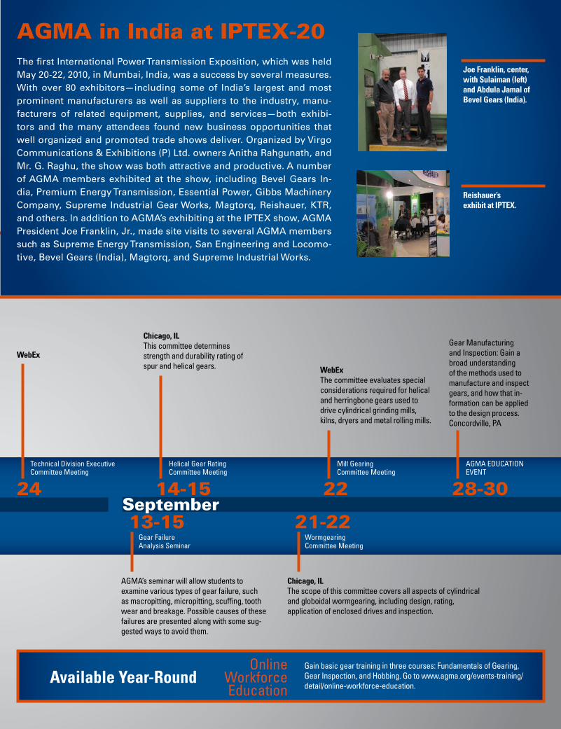
AGMA in India at IPTEX-20The first International Power Transmission Exposition, which was held May 20-22, 2010, in Mumbai, India, was a success by several measures. With over 80 exhibitors—including some of India’s largest and most prominent manufacturers as well as suppliers to the industry, manu-facturers of related equipment, supplies, and services—both exhibi-tors and the many attendees found new business opportunities that well organized and promoted trade shows deliver. Organized by Virgo Communications & Exhibitions (P) Ltd. owners Anitha Rahgunath, and Mr. G. Raghu, the show was both attractive and productive. A number of AGMA members exhibited at the show, including Bevel Gears In-dia, Premium Energy Transmission, Essential Power, Gibbs Machinery Company, Supreme Industrial Gear Works, Magtorq, Reishauer, KTR, and others. In addition to AGMA’s exhibiting at the IPTEX show, AGMA President Joe Franklin, Jr., made site visits to several AGMA members such as Supreme Energy Transmission, San Engineering and Locomo-tive, Bevel Gears (India), Magtorq, and Supreme Industrial Works.
Joe Franklin, center, with Sulaiman (left) and Abdula Jamal of Bevel Gears (India).
Reishauer’s exhibit at IPTEX.

18 gearsolutions.com
AGMA Foundation’s 2010 Annual Campaign Begins
Contact the AGMA500 Montgomery Street, Suite 350Alexandria, VA 22314-1581(703) 684-0211www.agma.org
General requests: [email protected] questions: [email protected] Expo information: [email protected]/Standards information: [email protected] Foundation: [email protected]
Board of DirectorsJim Bregi: President, Doppler Gear Company
Ivan Brems: CEO, Hansen Transmission International
Sharon Haverstock: Executive Vice President, Scot Forge Company
Richard Kuhr: Senior Application Engineer, ABA-PGT, Inc.
Bryan Lammers: Division Manager, Caterpillar, Inc.
Jeffrey Lawton: Vice President, Star Cutter Company
Gary Lehman: President & CEO, Fairfield Manufacturing Co., Inc.
Dana Lynch: President, Cleveland Gear/Columbia Gear
Gordon New: Managing Director, Ronson Gears Pty., Ltd.
Jack Nowlin: President, C-B Gear & Machine, Inc.
Bob Phillips: Senior Vice President, Gleason Cutting Tools Corp.
Roland Ramberg: President & CEO, The Gear Works-Seattle
Kyle Seymour: President & CEO, Xtek, Inc.
AGMA Leadership Executive CommitteeChairman: Dave BallardCorporate Manager, SEW-Eurodrive, Inc.
Chairman, TDEC: Dr. Phil TerryMetallurgist, Lufkin Industries
Chairman Emeritus: Dennis GimpertPresident, Koepfer America, LLC
Treasurer: Matt MondekPresident, Cotta Transmission Company, LLC
Chairman, BMEC: Leslie HennessyVP Strategic Planning & Business Development, Lovejoy, Inc.
StaffJoe T. Franklin, Jr., President Charles Fischer, Vice President Technical Division Jan Potter, Vice President Membership
The AGMA Foundation’s 2010 Annual Campaign will begin soon. Volunteers are making early contact with AGMA mem-bers and other friends to provide updates on the foundation’s activities and extend an invitation for “Campaign Champions” who pledge by August 13, 2010.
“We hope that you will join others in support of your industry, and your foun-dation,” says Joe C. Griffin, CEO and president of Griffin Gear and chair of AGMA Foundation’s 2010 Annual Cam-paign. “The foundation is grateful for all its generous supporters and recognizes them on its Web site and in its displays at Gear Expo and the AGMA/ABMA Annual Meeting.”
The Annual Campaign funds a variety of programs, including the following ex-amples from 2009:
• A grant to AGMA to videotape the “De-tailed Gear Design—Beyond Service Factors” advanced engineering seminar and format the content to be available in modules online with a study guide and “check for learning” tests. The on-line seminar is expected to go live in September of 2010 and will increase the reach of advanced engineering pro-grams to those unable to travel to semi-nar locations.
• A grant to the Gear Research Institute at Penn State to document how to compute transmission-error patterns on tooth working surfaces that are the cause of “ghost” error tones, thereby enabling manufacturing-source diag-nosis of such tones and commensurate accuracy specifications. The book will include a complete description of the proven CNC gear measurement meth-
odology required to accomplish the above, as well as numerous examples of successful implementation of the technology.
Corporate and individual pledges to the campaign can be e-mailed to [email protected], or you may fill out a pledge form at [www.agmafoundation.org]. Become a “Campaign Champion” by pledging on or before August 13!
“Excellence in gearing through the advancement of gear science, standards, and education.”

20 gearsolutions.com
be an ever-evolving project. There are many Web sites that sketch out the bare bones of a proper manual and offer the information free or for a mini-mal fee. If you are creating your first safety manual I strongly urge that you do a little surfing online to find these helpful sites. Their help will actually take hours off the time needed to create a proper manu-al. Don’t forget that many of these sites are govern-ment sponsored, or belong to government agencies, and if you use and reference them it may go a long way toward helping you in the case of an inspection or even a nasty lawsuit. Remember that this is only new to you. Many others in your position have gone
through similar processes, and now you can benefit from what they learned along the way.
4) Create checklists. This may be your biggest time-saver. Every time you have a safety meeting, training session, review or—God forbid—have an accident follow-up, there are certain items that must be cov-ered. It is very difficult if not impossible to remem-ber every item off the top of your head, and very time consuming to have to go through your safety manual in its entirety each time to be sure you cov-ered everything. I therefore suggest that you create short checklists for each of the scenarios that may occur so you can be sure that critical questions are asked and answered. This will really save a lot of time and make your job easier.
I hope these suggestions will help you in some way, and don’t forget that I would really appreciate your input! Any comments you can provide will appear in a future installment of this column.
I’ve been thInkIng about ways that we can simplify our safety systems and pro-cedures. What made me think about this was a conversation I had recently with the owner of a small company concerning his safety program. He was concerned about the amount of time and energy that would be required to maintain the program he’d instituted to protect his employees. This really made me start thinking about alternate ways that can be utilized to reduce the amount of time required by an accident, or even just a violation of the safety procedures adopted in a small shop. Most of the owners or managers of small enterprises that I know of want to do the right thing insofar as a safety program is concerned. Due to the busy nature of their jobs, however, finding the time to research the causes of accidents or to explain the importance of established safety procedures—or even punishing the lack of concern shown when established procedures are not followed—can take an extraordinary amount of their time that could otherwise be used to increase sales or production.So how do we help these small shops that don’t have the resources to employ one
or more individuals to concentrate on the safety program alone? I’ve been giving this a lot of thought lately, and I have come up with a few suggestions. I’d like to solicit any help you can offer, however, so please contact me at the e-mail address listed at the end of this column if you have any input you’d care to share. Here are my suggestions:
1) Use signage. The signs don’t have to be elaborate, or polished. With today’s easy to use computer programs anyone can make signs that make your safety concerns obvious and easy to understand. The key, as I see it, is making sure the sign’s message is clear and that it’s placed in a spot that’s highly visible. The signs should point out the obvious hazard, and the correct way of combating it. Make your signs as concise as possible, because you do not want employees spending lots of time reading it. It’s intended to be a reminder, not a trainer.
2) Provide training. I know, training your people takes valuable time away from the production floor. However, when you consider the time lost when an employee that has not been adequately trained has an accident that results in an injury to themselves or a fellow employee, the amount of time spent on proper safety train-ing is a small loss of production compared to the alternative.
3) Formal safety manual. Again, I know, creating a proper formal safety manual is a time consuming project, and as I have noted in previous columns it is and should
AbouT The AuThor: Terry McDonald is partner and manager of Repair Parts, Inc., and a member and past–chairman of the ANSI B11.11 Subcommittee on Safety Requirements for Construction, Care, and Use of Gear Cutting Equipment. Contact him at (815)
968–4499, rpi@repair–parts–inc.com, or [www.repair–parts–inc.com].
siteSAFETY
One key to implementing a successful safety program is to make sure that it’s as convenient as possible for everyone involved, including those who enforce it!
terryMcDonALDMember of the ANSI Subcommittee on Gear Safety
“Most owners of small
enterprises that I know
want to do the right
thing insofar as a safety
program is concerned,
but they’re already busy
due to their primary
responsibilities.”

22 gearsolutions.com
roughness using five consecutive sampling lengths over the filtered roughness profile. Rq (RMS) represents the root mean square roughness value that is obtained from the deviations of the filtered roughness profile over the evaluation length. Rp is the single highest peak above the centerline of the filtered profile. Pc is the pak count taken over 10mmof the filtered roughness profile. The peak is only read after the profile has passed through both a lower and upper variable preset threshold. The threshold lines are parallel to the centerline.
There is no relationship between gear quality and surface finish in AGMA standards. An AGMA document on gear tooth surface texture (AGMA906A94) is a guide to surface finish. Unfortunately there are still many who do not realize the significance of the surface finish on tooth flanks and believe—quite incorrectly—that it will be a self-correcting condition. Tests have indicated that the rubbing of any two surfaces reduces the initial roughness by no more than 25 percent. Modern-day surface measuring systems consist of a probe that
is powered to move across the involute surface. This probe sends signals to a computerized system that filters and evaluates the topography. The filter selection is critical in obtaining accurate findings. The M1 filter is the filter of choice. The three categories of roughness, waviness, and form can be seen. Some 40 years ago an RC resistor capacitor filter was popular, and it is still in use on older equipment. It is unreliable, however, and results can be distorted.
Another important criteria for accurate results is termed the “cutoff.” Sintered, P/M, and cast iron gears are porous and have a surface with many deep valleys. Gear flank surfaces should be measured in one direction from the tip to the root. The roughness wavelength is generally considered to be 1/20th of the tooth length.
the term “surface texture” is used to describe the deviations from what is considered as a nominally perfectly smooth surface. The term can be further defined as “the repetitive or random deviation of the normal surface that forms the three-dimensional topography of the surface.” The surface roughness does not follow a true geometric pattern; there will always be a wide assortment of peaks and valleys. These surface variations include flaws, waves, roughness, and the direction of the main surface pattern.
In the 7th International Conference of Metrology and Properties of Engineering Surfaces in 1997, gear surface topography can be characterized due to the noise by three parameters that describe the profile undulations. Irrespective of the finishing process the differences are in amplitude, wavelength, and the direction of the undulations. They have a direct correlation with the decibel level. Grinding creates the worst conditions as undulations are produced with the highest amplitude, the longest wavelength, and in a direction almost perpendicular to the path of contact. Conventional honing is used to reduce the amplitude and create a more favorable undulation direction. The surface finish that is determined will also consist of a series of measurements above and below a mean surface line.
In the practice of gearing, the gear’s performance and wear is affected by how extreme the levels of roughness are. With all gear manufacture it is important to minimize these extremes. More than a dozen roughness parameters are specified in ASME B46.1-1995. The arithmetical average of the peak to valley deviations provides the roughness measurement. Compact and battery operated surface instruments of low cost provide the RMS (root mean square average) in microinches. In lubrication the ratio of the fluid film thickness to peak-to-valley surface roughness provides the specific film thickness. In recent times a more popular measurement is Ra, or “Arithmetic Mean Roughness Value.” In other words, the arithmetic average value of the filtered roughness profile that can be determined from the deviations above the centerline and within a specific evaluation length. Rmax (maximum individual peak-to-valley) dimensions obtained from five sampling lengths within the evaluation length. RzDIN is the arithmetic average maximum mean peak-to-valley height of
“The gear’s performance
and wear is affected by
how extreme the levels of
roughness are, and with
all gear manufacture it
is important to minimize
these extremes.”
TOOTHtipS
What is the true definition of “surface finish,”
and how can the extremes of roughness be
minimized? A deeper understanding of this
concept will help overcome challenges.
williamCrosherAuthor, engineer, and former director of the National Conference on Power Transmission
William P. Crosher is former director of the National Conference on Power Transmission, as well as former chairman of the AGMA’s Marketing Council and Enclosed Drive Committee. He was resident engineer-North America for Thyssen Gear Works, and later at Flender Graffenstaden. He is author of the book Design
and Application of the Worm Gear.
AbouT The AuThor:

Gearing Up Your Business
You speak, we listen, and together we develop solutions to your complex
manufacturing challenges. With years of experience in designing and
manufacturing gears, CGC also understands the importance of project
management and logistics, ensuring on-time delivery of high-quality products
made to meet AGMA, ISO, and DIN standards. So give us a call, and we’ll give
you a listen.
330 Pinebush Rd. | Cambridge, Ontario | N1R-1Z6 | Canada
Carolina Gear& Components Ltd.
Capabilities Current Future
Gear Cutting 8m 10m
Gear Gashing 5m 10m
Gear Grinding 1.5m 2.8m
Machine turning 2m 4.5m
P: 519-623-8806 | F: 519-623-4886 | E: [email protected] | www.cgc-group.net

24 gearsolutions.com
COMPANYPROFILE
By Russ Willcutt
COMPANYPROFILE
founded on the basis of a proprietary
technology, this company has continued
to lead the way in developing cutting-edge
thermal processes and equipment.
Surface Combustion, inc.
J
To LeArn more: Call (800) 537-8980, e-mail [email protected], or go to [www.surfacecombustion.com].
erything from atmosphere to vacuum equipment, continuous furnaces, batch furnaces, and all of the han-dling and companion equipment that’s required such as control sys-tems and auxiliary atmosphere gen-erators. Someone can simply tell us what they’d like to do and we can ad-vise them across technology lines,” he says. “That allows us to be very objective, and to make suggestions based on their particular application. Having such a broad range of prod-ucts also helps should one market experience a downturn, since diversi-fication can provide protection from such trends.”
In addition to automotive, Surface Combustion is also involved in off-road, aerospace, and even govern-ment ordnance work such as devel-oping systems for the incineration of chemical weapons. “We also provide equipment that carburizes or through-hardens gears, nuts, bolts, bearings, and the like,” Goodman says. “So that broad range of experience allows us to listen to a customer’s needs and suggest a number of technolo-gies we believe they should consider, complete with a list of pros and cons for each.”
During his three decades with the company, Goodman says that he’s seen many advances being made, es-pecially in the areas of controls, sen-sors, and even the material handling aspects of the systems it designs and manufactures. “The changes that have occurred in things such as robot-ics, carbon control, and the types of insulation that are now available are simply astounding,” he says, “and one of the reasons we’re so plugged in to these advents is this fresh stream of young minds we constantly have flow-ing into the company. It’s just a great way of keeping us at the leading edge of developments in thermal process-ing. We always want to be at least two steps ahead of everybody else so that we can provide our customers with the best value possible.”
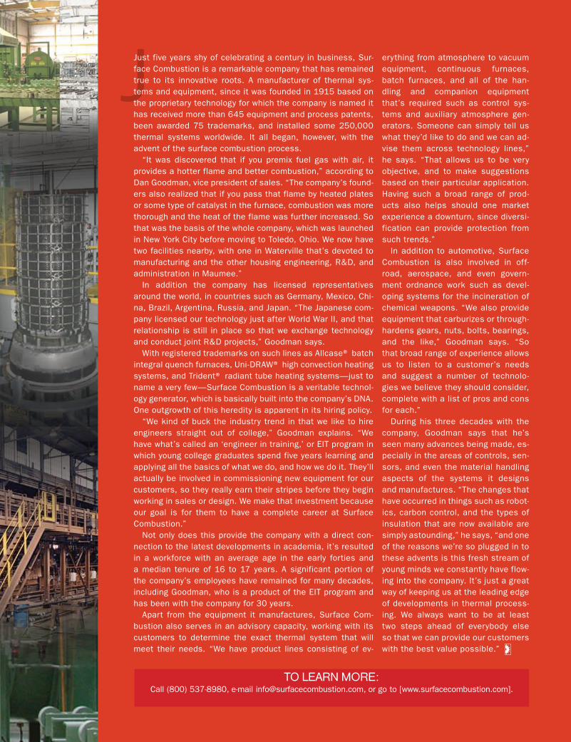
Just five years shy of celebrating a century in business, Sur-face Combustion is a remarkable company that has remained true to its innovative roots. A manufacturer of thermal sys-tems and equipment, since it was founded in 1915 based on the proprietary technology for which the company is named it has received more than 645 equipment and process patents, been awarded 75 trademarks, and installed some 250,000 thermal systems worldwide. It all began, however, with the advent of the surface combustion process.
“It was discovered that if you premix fuel gas with air, it provides a hotter flame and better combustion,” according to Dan Goodman, vice president of sales. “The company’s found-ers also realized that if you pass that flame by heated plates or some type of catalyst in the furnace, combustion was more thorough and the heat of the flame was further increased. So that was the basis of the whole company, which was launched in New York City before moving to Toledo, Ohio. We now have two facilities nearby, with one in Waterville that’s devoted to manufacturing and the other housing engineering, R&D, and administration in Maumee.”
In addition the company has licensed representatives around the world, in countries such as Germany, Mexico, Chi-na, Brazil, Argentina, Russia, and Japan. “The Japanese com-pany licensed our technology just after World War II, and that relationship is still in place so that we exchange technology and conduct joint R&D projects,” Goodman says.
With registered trademarks on such lines as Allcase® batch integral quench furnaces, Uni-DRAW® high convection heating systems, and Trident® radiant tube heating systems—just to name a very few—Surface Combustion is a veritable technol-ogy generator, which is basically built into the company’s DNA. One outgrowth of this heredity is apparent in its hiring policy.
“We kind of buck the industry trend in that we like to hire engineers straight out of college,” Goodman explains. “We have what’s called an ‘engineer in training,’ or EIT program in which young college graduates spend five years learning and applying all the basics of what we do, and how we do it. They’ll actually be involved in commissioning new equipment for our customers, so they really earn their stripes before they begin working in sales or design. We make that investment because our goal is for them to have a complete career at Surface Combustion.”
Not only does this provide the company with a direct con-nection to the latest developments in academia, it’s resulted in a workforce with an average age in the early forties and a median tenure of 16 to 17 years. A significant portion of the company’s employees have remained for many decades, including Goodman, who is a product of the EIT program and has been with the company for 30 years.
Apart from the equipment it manufactures, Surface Com-bustion also serves in an advisory capacity, working with its customers to determine the exact thermal system that will meet their needs. “We have product lines consisting of ev-

By Steven Katz
No one wants to experience bearing failure, but close study of all the factors involved will allow you to help avoid the associated costs and downtime in the future.
analyzing Bearing Failure
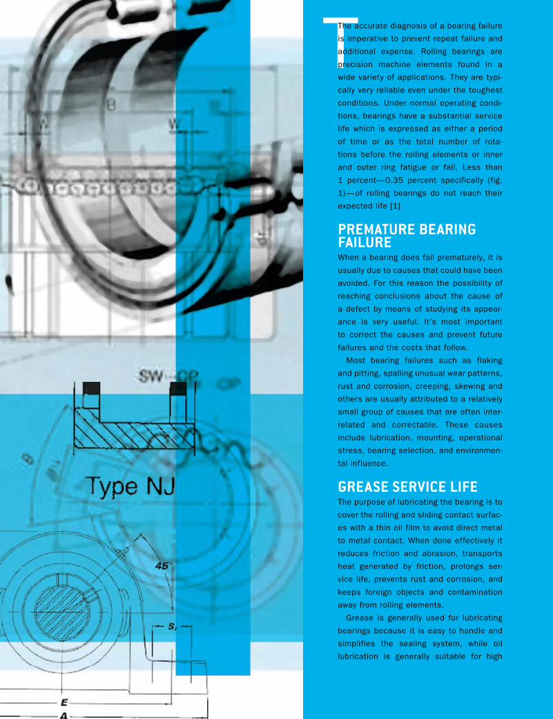
TThe accurate diagnosis of a bearing failure
is imperative to prevent repeat failure and
additional expense. Rolling bearings are
precision machine elements found in a
wide variety of applications. They are typi-
cally very reliable even under the toughest
conditions. Under normal operating condi-
tions, bearings have a substantial service
life which is expressed as either a period
of time or as the total number of rota-
tions before the rolling elements or inner
and outer ring fatigue or fail. Less than
1 percent—0.35 percent specifically (fig.
1)—of rolling bearings do not reach their
expected life [1].
PreMAture beAring FAiLureWhen a bearing does fail prematurely, it is
usually due to causes that could have been
avoided. For this reason the possibility of
reaching conclusions about the cause of
a defect by means of studying its appear-
ance is very useful. It’s most important
to correct the causes and prevent future
failures and the costs that follow.
Most bearing failures such as flaking
and pitting, spalling unusual wear patterns,
rust and corrosion, creeping, skewing and
others are usually attributed to a relatively
small group of causes that are often inter-
related and correctable. These causes
include lubrication, mounting, operational
stress, bearing selection, and environmen-
tal influence.
greAse serviCe LiFeThe purpose of lubricating the bearing is to
cover the rolling and sliding contact surfac-
es with a thin oil film to avoid direct metal
to metal contact. When done effectively it
reduces friction and abrasion, transports
heat generated by friction, prolongs ser-
vice life, prevents rust and corrosion, and
keeps foreign objects and contamination
away from rolling elements.
Grease is generally used for lubricating
bearings because it is easy to handle and
simplifies the sealing system, while oil
lubrication is generally suitable for high

speed or high temperature operations. Generally lubrication fail-
ures occur due to: using the wrong type of lubricant; too little
grease/oil; too much grease/oil; mixing of grease/oil; and con-
tamination of the grease/oil by objects or water.
While we have spoken about a normal bearing service life it is
also important to take into consideration the normal grease ser-
vice life, as the two should be considered together to maximize
bearing life. Grease service life is the time over which proper
Fig. 1: Examples of bearing failure.
28 gearsolutions.com
bearing function is sustained by a particular quantity and cat-
egory of grease. This is especially critical in pump, compressor,
motor, and super-precision applications.
Mounting AnD instALLAtionIt is critical in the mounting and installation process to pay strict
attention to the following:
Use of proper tools and ovens/induction heaters. Use a sleeve
to impact the entire inner ring face of the ring being press fit.
Verify the shaft and housing tolerances. If the fit is too tight
you will create too much preload, and if the fit is too loose you
will create too little preload, which may allow the shaft to rotate
or creep in the bearing. Check for proper diameters, roundness,
and chamfer radius.
Avoid misalignment or shaft deflection. This is especially criti-
cal in mounting bearings that have separable components such
as cylindrical roller bearings where successful load bearing and
optimal life are established or diminished at installation.
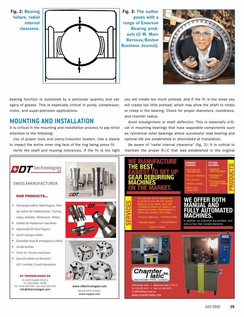
Be aware of “radial internal clearance” (fig. 2): It is critical to
maintain the proper R.I.C that was established in the original
Fig. 2: bearing failure, radial
internal clearance.
Fig. 3: the author poses with a
range of Emerson bearing prod-
ucts (© w. Marc bernsau/boston
business Journal).
Prod
ucts
sErV
IcEs
standard FEaturEs:
• Automatic Air Operated door
• Operator Interface
• PLC controls
• Filtration system
• Work Light inside hood
oPtIonal FEaturEs:
• Additional deburring heads
• Automatic air chucking
• Thermostatically controlled heating element.
Our customer service response time is second to none. We offer contract deburring of your gears, along with rebuilding all makes and models of gear deburring machines. Chamfermatic is a full-service supplier to the industry.
• Contract Deburring
• Machine rebuild
• Grinding wheels
• Carbide Deburrs
• Osborn brushes
WE oFFEr both manual and Fully automatEd machInEs.In addition our machines are portable, and carry a Two Year Limited Warranty.
WE manuFacturE thE bEst, EasIEst to sEt uP gEar dEburrIng machInEs on thE markEt.
7842 Burden Road • Machesney Park, IL 61115 Tel: 815-636-5082 • Fax: [email protected]
www.chamfermatic.com
JULY 2010 29
design. The standard scale in order of
ascending clearance is C2, C0, C3, C4,
and C5. The proper clearance for the
application is critical in that it allows for
the challenges of:
• Lubrication. A proper film of lubricant
must be established between the rolling
elements. Reducing internal clearance
and impeding lubricant flow can lead to
premature failure.
• Shaft fit. It is inevitable that there can be
a reduction in the radial internal clear-
ance when the bearing is press fit.
• Heat. In the normal operation of bear-
ings there is heat produced that cre-
ates thermal expansion of the inner and
outer rings. This can reduce the internal
clearance, which will reduce the optimal
bearing life.
oPerAtionAL stress AnD seLeCtionIt is generally the exception to find a bear-
ing that has been improperly designed
into an application. However, factors with-
in the larger application may change. If
loads become too high, overloading and
early fatigue may follow. If they are too
low, skidding and improper loading of the
rolling elements occur. Early failure will
follow in each situation. Similar issues
arise with improper internal clearance.
The first sign of these issues will be
unusual noises and/or increased tem-
peratures.
Increased temperature. Bearing tem-
perature generally rises with start up and
stabilizes at a temperature slightly lower
than at start up (normally 10 to 40 C high-
er than room temperature). A desirable
bearing temperature is below 100 C.
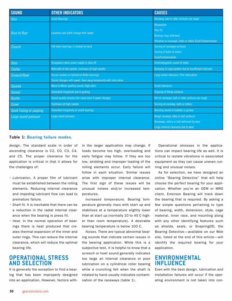
Noises. There are typical abnormal bear-
ing sounds that indicate certain issues in
the bearing application. While this is a
subjective test, it is helpful to know that a
screech or howl sound generally indicates
too large an internal clearance or poor
lubrication on a cylindrical roller bearing
while a crunching felt when the shaft is
rotated by hand usually indicates contami-
nation of the raceways (table 1).
Operational stresses in the applica-
tions can impact bearing life as well. It is
critical to isolate vibrations in associated
equipment as they can cause uneven run-
ning and unusual noises.
As for selection, we have designed an
online “Bearing Detective” that will help
choose the perfect bearing for your appli-
cation. Whether you’re an OEM or MRO
client, Emerson Bearing will track down
the bearing that is required. By asking a
few simple questions pertaining to type
of bearing, width, dimension, style, cage
material, inner race, and mounting along
with any other identifying features such
as shields, seals, or SnapringOD, the
Bearing Detective—available on our Web
site, listed at the end of this article—will
identify the required bearing for your
application.
environMentAL inFLuenCeEven with the best design, lubrication and
installation failures will occur if the oper-
ating environment is not taken into con-
table 1: bearing failure modes.
SOUND OTHER INDICATORS CAUSESHiss Small Bearings Raceway, ball or roller surfaces are rough
Buzz to Roar Loudness and pitch change with speed
Resonation
Poor Fit
Bearing rings deformed
Vibration or raceways, balls or rollers Dust/Contamination
Crunch Felt when bearings is rotated by hand Scoring of raceways surfaces
Scoring of balls or rollers
Dust/Contamination
Hum Disappears when power supply is shut off Electromagnetic sound of motor
Clatter Noticable at low speeds, continous at high speeds Bumping in cage pockets due to insufficient lubricant
Screech/Howl Occurs mainly on Cylindrical Roller bearings
Sound changes with speed. Goes away temporarily with lubrication
Large radial clearance. Poor lubrication
Squeak Metal to Metal spalling sound. High pitch Small clearance.
Squeal Generated irregularly due to grating Slipping of fitting surfaces
Rustle Sound quality remains the same even if speed changes Dirt or raceways, ball or roller surfaces are rough
Growl Continous at high speeds Scoring on raceway, balls or rollers
Quiet Fizzing or popping Generated irregularly on small bearings Bursting sound of bubbles in grease
Large sound pressure Large sound pressure Rough raceway, roller or ball surfaces
Raceways, rollers or ball deformed by wear
Large internal clearance due to wear
30 gearsolutions.com

sideration. While there are many potential
issues the primary ones are:
Dust and dirt, which can aggressively
contaminate a bearing. Great care should
be given to use proper sealing techniques.
Aggressive media or water. Once again,
sealing is primary. The use of specialty
type seals is recommended such as pump
mechanical or labyrinth-style seals that do
not score the shaft.
External heat. The ambient operating
temperature mandates many choices in
radial internal clearance, high temperature
lubricants, intermittent or continuous run-
ning, and others that affect bearing life.
Current passage or electrolytic corrosion.
If current is allowed to flow through the
rolling elements, sparks can create pitting
or fluting on the bearing surfaces. This
should be corrected by creating a bypass
circuit for the current or through the use
of insulation on or within the bearing. This
should be an inherent design consideration
in applications such as wind turbines and
all power generating equipment.
ConCLusionTo sum up our conversation, the first
step in the overall prevention of bearing
failure lies in the consideration of bearing
technologies that are most suitable to the
application with regard to specifications,
recommendations, maintenance strate-
gies, fatigue life, and wear resistance of
the bearing in relation to the application.
That said, premature bearing failure within
a proper application is typically attributed
to one or more of the causes discussed—
lubrication, mounting, operational stress,
and bearing selection or environmental
influence—which can and should be cor-
rected in order to avoid future bearing
failures and additional cost.
reFerenCes:1) FAG Bearing Antriebtechnik 18 from 1979.
2) Barden Corporation. Machine Tool
technical bulletin for Engineering and
Lubrication. 2010.
3) FAG Bearings Corp. Rolling Bearing Damage.
Publ. No. WL 82 102/2 December 1997.
4) Fersa Bearings. Roller Bearings: Failure
Diagnosis. 2009.
5) Koyo Bearing Corp. Rolling Bearings:
Failures, Causes and Countermeasures.
Catalog No. 322E. December 1995.
6) NTN Bearing Corp. Products and Technology.
Care and Maintenance of Bearings. 2009.
about the author:
Steven Katz is the president of Action and Emerson Bearing. Call (800) 225-4587 or visit [www.emersonbearing.com].
JULY 2010 31


By Ed Sullivan
As is the case with any manufacturing process, choosing the right ultrasonic cleaning method can mean the difference between wasting time and making money.
in
sigh
ts int
o U
ltra
sonic
Cleaning
IIf you’re looking for ultrasonic gear-cleaning
equipment, you may begin your search by
logging onto the Internet or poring over spec
sheets in hopes of finding a solution that
best suits your needs. Chances are you may
quickly become mired in a blizzard of techni-
cal terms and specifications about transduc-
ers, frequencies, harmonics, and chemistry
that leave you more confused than informed.
Although the superior benefits of ultrasonic
cleaning may perfectly suit your needs, how
do you unravel the complexities and obscure
language of the technology when all you really
want is a “plug & play” solution?
In the vast majority of cases, the users who
can benefit from ultrasonic cleaning systems
should not need to possess an in-depth
knowledge about the science behind the tech-
nology. Nor should they have to agonize over
choices in product design, accessories, or
the chemistry of cleaning solutions used with
ultrasonic systems.
“Ultrasonic cleaning is a very productive
technology, but I believe that sometimes the
equipment manufacturers are overly enam-
ored with the technical aspects of it, making
decisions more complex than necessary,”
says David Arata, whose experience with the
field of ultrasonics goes back over 40 years.
He warns that while choosing any process
equipment is hardly a no-brainer, it should not
be overlooked that in many instances—par-
ticularly with inexperienced users—it is critical
that the equipment marketer assist that user
in making the best equipment selection.
PLug & PLAy soLutionArata has a U.S. patent as co-inventor of a
unique ultrasonic cleaning generator circuit,
and he has traveled and met with engineers
from around the world to understand their
requirements for precision cleaning. He is
now a marketing and technology executive
with Omegasonics where he supports the test
lab, the facility where new or demanding appli-
cations for ultrasonic equipment are proven
according to specifications that are estab-
lished with prospective customers who are
uncertain about their particular application.
Rather than dazzling such customers in
sigh
ts int
o U
ltra
sonic
Cleaning
with technological information they’ll prob-
ably never need again, Arata’s laboratory
approach calls for thoroughly and accu-
rately determining the customers needs
and expectations, which he feels are vital
to simplifying their selection processes and
making their ultrasonic cleaning solution
truly plug & play friendly.
“We have extensive experience in quite a
few industrial sectors,” he says, “including
aerospace, gear manufacturing, food and
pharmaceuticals, military, and utilities. Yet
in virtually every sector the customer may
have unique or changing production process-
es that must be addressed for them to fully
realize the productivity and quality benefits
of ultrasonic cleaning.”
As examples of diverse working environ-
ments Arata cites U.S. Navy ships that use
a range of portable ultrasonic cleaning units
to maintain and service components of vari-
ous vessel systems. Large and small energy
producers clean hundreds of large and
small parts such as components of hydro-
and gas-powered turbines that depend on
thorough and efficient cleaning to maximize
uptime, and each year more gear manufac-
turers are learning the benefits of this tech-
nology as well.
Traditionally, parts cleaning has been labo-
rious and costly. “The last time we performed
an outage on one of our gas turbines, we
rented a commercial parts cleaning agitation-
type machine,” says Kim Townsend, mainte-
nance foreman for power provider Farmington
Electric. “We would wash the parts for 12 to
14 hours, then take them out and have to
hand clean them. I actually had four guys tied
up for probably a week of eight-hour days,
sitting around the table with little brushes
scrubbing and scrubbing and scrubbing.”
The reason for the extra hand-cleaning was
that the rental machine had not done the job.
The turbine contains a thousand bolts and
several hundred turbine blades, so it was
a very time-consuming process. “Using the
Omegasonics cleaning system, we were able
to get all of the parts cleaned up in a matter
of four days,” he says, “and I only devoted
one person to it.”
“Ultrasonic cleaning is a fairly straight-
forward technology,” Arata adds, “but it is
nevertheless vital that the cleaning system
satisfy user needs, which should be clearly
identified by the sales rep teaming along
with the prospective user.”
QuiCk ConsiDerAtionsWhen proving an application at Omegasonics,
Arata’s associates ask prospective custom-
ers to send sample parts to the test lab so
that the best ultrasonic cleaning system may
be determined. “While one of our models
is likely to fit the need, it is important to
know how clean the parts should be,” Arata
explains. “That consideration will impact the
choice of equipment, the cleaning solution
chemistry, and the method of rinsing and
drying cleaned parts.”
Work time is a critical ingredient of the
evaluation process. In some instances a
part may require immersion in the ultrasonic
cleaner for 10 or 15 minutes. This amount of
time may impact the choice of a larger unit,
or perhaps multiple smaller units that can be
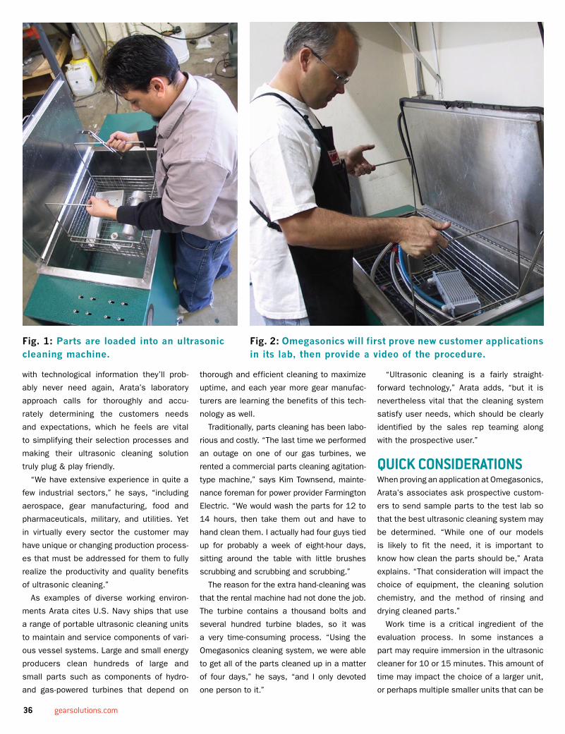
Fig. 2: omegasonics will first prove new customer applications in its lab, then provide a video of the procedure.
Fig. 1: Parts are loaded into an ultrasonic cleaning machine.
36 gearsolutions.com

moved to multiple locations if necessary or
advantageous.
He adds that various models of equipment,
ranging from tabletop models to large indus-
trial washers and restoration systems, feature
built-in portability. “A tabletop model may be
very appropriate for smaller applications or
those when it’s advantageous to move the
cleaner to the proximity where parts are being
serviced,” he says. “I believe we have been
somewhat unique in designing cleaning sys-
tems that facilitate today’s ‘cellular’ manufac-
turing configurations. Even our large models
have wheels, so they may be moved easily if a
process changes configuration or if users wish
to share equipment between locations.”
Arata explains that the selection of cleaning
solution that is added to the ultrasonic bath
water is another variable that is determined by
at the test lab. “When we are proving a specif-
ic customer’s application, we make a cleaning
solution recommendation. The solution can be
supplied directly by us, or in many instances
bought sourced from commercial vendors.
Once the optimum chemistry is decided the
optimum water temperature and ultrasound
transducer frequency range is determined.
Once these factors are determined, the use
of our equipment is literally ‘set it and forget
it’ and requires no other setup than to pull the
cleaner out of the box and plug it in.”
He notes that whenever Omegasonics
proves a customer application at the lab, the
cleaning process and results are recorded on
video. If the customer prefers, the video can
be emailed to them for review or further dis-
cussion. “This is pretty much all the documen-
tation they need to evaluate our recommended
solution,” Arata says. “It also provides anoth-
er demonstration of how the equipment is
truly ‘plug & play.’ But more importantly, the
customer doesn’t have to contend with the
somewhat esoteric technology of ultrasonic
cleaning. They simply push a button to enjoy
its benefits. The technical savvy is completely
transparent to the customer, because all the
necessary hands-on expertise is provided by
us. And that usually makes life a lot easier for
them.”
Fig. 3: Ultrasonic cleaning is a fairly straightforward process, with little training required.
about the author:
Ed Sullivan is a technology writ-er based in Hermosa Beach, California. For more information about Omegasonics contact Frank Pedeflous at (805) 583-0875, [email protected], or [www.omegasonics.com].
JULY 2010 37

By Nicholas Bugliarello, Biji George, Don Giessel, Dan McCurdy, Ron Perkins, Steve Richardson, and Craig Zimmerman
Different heat treating processes—as well as the materials being treated—impart particular qualities in your gears. allow Bodycote to provide a deeper understanding of your options.
f o r G e a r s
HHeat treatment is a critical and
complex element in the manu-
facturing of gears that greatly
impacts how each will perform
in transmitting power or carrying
motion to other components in
an assembly. Heat treatments
optimize the performance and
extend the life of gears in service
by altering their chemical, met-
allurgical, and physical proper-
ties. These properties are deter-
mined by considering the gear’s
geometry, power transmission
requirements, stresses at dif-
ferent points within a gear under
load, load cycling rates, mate-
rial type, mating part designs,
and other operating conditions.
Heat treatments improve physi-
cal properties such as surface
hardness, which imparts wear
resistance to prevent tooth and
bearing surfaces from simply
wearing out. Heat treatments
also improve a gear’s fatigue
life by generating subsurface
compressive stresses to prevent
pitting and deformation from
high contact stresses on gear
teeth. These same compres-
sive stresses prevent fatigue
failures in gear roots from cyclic
tooth bending. Physical proper-
ties such as surface hardness,
core hardness, case depth, duc-
tility, strength, wear resistance
and compressive stress pro-
files can vary greatly depending
on the type of heat treatment
applied. For any given type of
heat treatment the results can
be tailored by modifying pro-
cess parameters such as heat-
ing source, temperatures, cycle
times, atmospheres, quench
media, and tempering cycles
to meet specific application
requirements.
Besides selecting heat treat-
ments that will produce a set
of desired physical properties,
manufacturing engineers want
to minimize distortion of dimen-
sions from treatment such that
final proper fit into a gearbox
can be achieved. Many gears
are machined into an oversized
condition prior to heat treat-
ment so that a planned amount
of grind stock may be removed
after the process in order to
meet dimensional requirements.
By selecting heat treatment
processes where distortion is
reduced, the amount of grind
stock needed may be reduced
to minimize machining on hard-
ened surfaces after heat treat-
ment and thereby reduce the
overall costs of manufacturing.
Removing too much of the outer-
most portion of a case hardened
gear that distorted excessively
will also negatively impact the
fatigue properties and wear life
performance. Some heat treat-
ment processes are designed
to treat the entire surface of a
gear, while others are selective
in nature. Induction hardening
or selective heating may be
employed to harden just the
gear teeth only, which can be
an effective method of reducing
the distortion in a gear. Masking
of journals and keyways may
be employed in case harden-
ing processes to keep them
soft and allow for easier grind
stock removal after heat treat-
ment. Reduction of distortion by
intelligent heat treatment pro-
cess design allows manufactur-
ing engineers to improve the
performance and/or reduce the
overall costs of manufacturing
a gear.
In all cases, gear design engi-
neers understand that heat
treatments play a complex and
vital role in both the ease of
manufacturing and the perfor-
mance of the gears they make.
Today, many options exist for
the heat treatment of gears.
Proper selection and design of
the heat treatment process can
greatly affect performance, ease
of manufacture, and economics
of a component. This paper will
focus on a variety of different
processes and highlight some
benefits and disadvantages of
each.
heAt treAting bAsiCsTo understand heat treating, a
basic knowledge of metallurgy
is needed. Iron, when combined
with small percentages of car-
bon, forms steel. Plain carbon
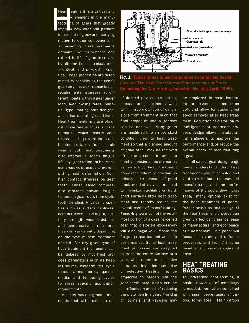
Fig. 1: typical press quench equipment and tooling design (Source: the heat treat Doctor: Fundamentals of Press Quenching by Dan herring, Industrial heating april, 1995).
steels typically contain 1 percent or less
carbon in combination with iron. The
maximum hardness that any plain carbon
steel can achieve during heat treatment is
primarily a function of its carbon content.
Higher carbon content steels are capable
of being hardened to higher hardness val-
ues than lower carbon content steels. To
make alloy steels, small percentages of
other elements such as Cr, Ni, Mo, Si, B,
V, Ti, Al, N, Nb, W, and Cu (to name the
most common) are added to steel. These
alloying elements are added in order to
increase hardenability or enhance specif-
ic properties such as toughness or resis-
tance to softening from heat build-up.
For heat treaters the higher hardenability
allows for slower quenching, which means
distortion can be kept to lower levels in
more highly alloyed steels. Steels can
Fig. 2: two fully automated low pressure carburizing furnace lines (bodycote-livonia, Michigan).
Fig. 3: hardness and compressive stress profiles generated by lPC (compare to fig. 4).
40 gearsolutions.com

be annealed by thermally processing at
a high temperature and slow cooling to
soften it. In this soft and malleable state
it can be machined, formed, hobbed, and
ground easily into a desired shape. What
makes steel industrially important is that
it can be hardened after the material
has been formed or shaped in the soft
state to a desired geometry. By use of
a thermal processing cycle where steel
is heated to austenitizing temperatures
and rapidly quenched, the near-finished
components can be hardened to improve
wear resistance, strength, and hardness.
After quenching to the maximum hard-
ness achievable, which is determined by
the steel’s carbon content, the steel may
then be tempered down to a lower hard-
ness to improve ductility and toughness
at the expense of slightly reducing the
strength, hardness, and wear characteris-
tics of the material.
What actually occurs in steel during
heat treating are phase transformations
as atoms rearrange themselves into dif-
ferent crystal structures. The starting
point of most heat treated parts is an
annealed material. In fact, when purchas-
ing steel it is generally in the annealed
condition. An annealed structure is a com-
bination of primarily ferrite (Fe, pure iron)
and iron carbide (Fe3C, cementite). These
will be in the form of alternating layers of fer-
rite and Fe3C (pearlitic structure), or ferrite
Fig. 4: hardness and compres-sive stress profiles generated by atmosphere carburizing (compare to fig. 3).
JULY 2010 41
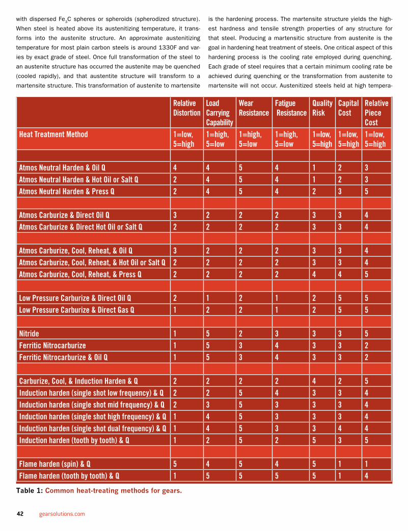
with dispersed Fe3C spheres or spheroids (spherodized structure).
When steel is heated above its austenitizing temperature, it trans-
forms into the austenite structure. An approximate austenitizing
temperature for most plain carbon steels is around 1330F and var-
ies by exact grade of steel. Once full transformation of the steel to
an austenite structure has occurred the austenite may be quenched
(cooled rapidly), and that austentite structure will transform to a
martensite structure. This transformation of austenite to martensite
is the hardening process. The martensite structure yields the high-
est hardness and tensile strength properties of any structure for
that steel. Producing a martensitic structure from austenite is the
goal in hardening heat treatment of steels. One critical aspect of this
hardening process is the cooling rate employed during quenching.
Each grade of steel requires that a certain minimum cooling rate be
achieved during quenching or the transformation from austenite to
martensite will not occur. Austenitized steels held at high tempera-
Relative Distortion
Load Carrying Capability
Wear Resistance
Fatigue Resistance
Quality Risk
Capital Cost
RelativePiece Cost
Heat Treatment Method 1=low, 5=high
1=high, 5=low
1=high, 5=low
1=high, 5=low
1=low, 5=high
1=low, 5=high
1=low, 5=high
Atmos Neutral Harden & Oil Q 4 4 5 4 1 2 3Atmos Neutral Harden & Hot Oil or Salt Q 2 4 5 4 1 2 3Atmos Neutral Harden & Press Q 2 4 5 4 2 3 5 Atmos Carburize & Direct Oil Q 3 2 2 2 3 3 4Atmos Carburize & Direct Hot Oil or Salt Q 2 2 2 2 3 3 4 Atmos Carburize, Cool, Reheat, & Oil Q 3 2 2 2 3 3 4Atmos Carburize, Cool, Reheat, & Hot Oil or Salt Q 2 2 2 2 3 3 4Atmos Carburize, Cool, Reheat, & Press Q 2 2 2 2 4 4 5 Low Pressure Carburize & Direct Oil Q 2 1 2 1 2 5 5Low Pressure Carburize & Direct Gas Q 1 2 2 1 2 5 5 Nitride 1 5 2 3 3 3 5Ferritic Nitrocarburize 1 5 3 4 3 3 2Ferritic Nitrocarburize & Oil Q 1 5 3 4 3 3 2 Carburize, Cool, & Induction Harden & Q 2 2 2 2 4 2 5Induction harden (single shot low frequency) & Q 2 2 5 4 3 3 4Induction harden (single shot mid frequency) & Q 2 3 5 3 3 3 4Induction harden (single shot high frequency) & Q 1 4 5 3 3 3 4Induction harden (single shot dual frequency) & Q 1 4 5 3 3 4 4Induction harden (tooth by tooth) & Q 1 2 5 2 5 3 5 Flame harden (spin) & Q 5 4 5 4 5 1 1Flame harden (tooth by tooth) & Q 1 5 5 5 5 1 4
table 1: Common heat-treating methods for gears.
42 gearsolutions.com

ture and quenched too slowly down to ambient temperature will not
transform from austenite to a martensitic structure. They will instead
revert back a softer mix of ferrite and cementite again.
Table 1 summarizes the methods in common use today for heat
treatment of gears. Each method has its place; some are perfect
for high volumes, while others are practical only on a piece-by-piece
basis. Some improve all metallurgical properties, while others
improve only one or two.
neutrAL hArDeningThere are two general classifications of heat treatments used for
hardening steels: neutral hardening, and case hardening. Neutral
hardening refers to maintaining the carbon potential of the atmo-
sphere at the same percentage as the carbon in the steel during
the hardening cycle. This means that carbon is entering and leav-
ing the surface of the steel at the same rate, and no net gain or
net loss of carbon atoms inside the surface of the steel occurs.
Many gears are neutral hardened, but for the most demanding
applications case hardening processes, such as carburizing and
nitriding, are the preferred methods due to their improved wear
characteristics and mechanical properties.
AtMosPhere CArburizingCarburizing, the most widely used form of surface hardening, is
the process of diffusing carbon into the surface of low carbon
steel at elevated temperatures. This results in a high carbon
case forming just inside the surface of a low carbon component.
During quenching from austenitizing temperatures the austenite
will transform to martensite, and the higher carbon case will have
a high hardness while the lower carbon core material will have a
lower hardness. The goal of this process is to produce a hard,
strong, wear resistant outer surface while retaining a softer, duc-
tile tough core.
When austenite transforms to martensite during quenching,
a volume expansion occurs in the material and it grows. The
volumetric expansion in the case is greater than the volume
expansion in the lower carbon, lower hardness core structure.
This difference in size changes puts the carburized surface of the
part into a state of compression, which makes it stronger. For
example, when a force is applied to a gear tooth, it first has to
overcome these compressive forces before beginning to put the
surface of the tooth in tension. In order to deform this material,
it requires a force that exceeds the combination of overcoming
the compressive stresses present in addition to the normal yield
strength of the material. These compressive stresses caused
by differences in volume expansion rates between the case and
core improves the overall tensile and yield strength of the carbur-
ized case inside a gear tooth. It is these compressive stresses
that resist deformation from high contact stresses present as
gear teeth press and roll against each other. These compressive
stresses also increase fatigue life by helping to prevent cracking
JULY 2010 43

in tooth roots as the teeth are cyclically loaded and unloaded
with bending stresses. The high carbon, high hardness surface
of the carburized case also resists wear and scoring caused by
friction as gear teeth rub and wear against each other.
One can’t discuss heat treating gears without discussing
distortion, which occurs for a variety of reasons. One source is
pre-existing residual stresses present in the material caused by
prior operations such as steelmaking, rolling, forming, forging,
casting, machining, and grinding. As the material begins to heat
up during carburizing, these residual stresses present in the
material relieve and cause the gears to distort if these stresses
were large or non-uniform.
A second source of distortion is high temperature creep dur-
ing processing. Gravity is the enemy of many gear designs dur-
ing thermal processing, especially in carburising, where high
temperatures and long processing times are the norm. At high
temperatures, steel has little strength and can sag and bend
under gravity’s force if sections of a part are not properly sup-
ported or components not stood up or hung perfectly straight.
Spending the extra time to fixture parts correctly and designing
customized fixtures to properly support a gear during exposure
to high temperatures can save many hours of straightening and
machining afterwards. Some part shapes such as long shafts
are best racked in vertical orientations to maintain straightness
Fig. 5: lPC process: carburized case in gear root (left), carburized case in gear tooth (right).
Fig. 6: no presence of intergranular oxidation after lPC process.
Heat Treating Services:
Other Services Include:
Heat Treating Services:• Carburizing, Carbonitriding, Hardening• Marquenching for Distortion Control• Nitriding/Ferritic Nitrocarburizing• Induction Hardening• Gleason Press Quenching• Flame Hardening
Other Services Include:Aluminum Processing • Neutral Salt Bath Hardening • Stress Relieving • Tool Steel Processing • High Temperature Alloy Age Hardening • Long Parts • Stainless Steel Processing • Sub-zero Treating • Metallurgical Consulting • Annealing & Normalizing
ADDITIONAL MANUFACTURING SERVICES AVAILABLE
5701 Mariemont Avenue • Cincinnati OH 45227
Phone (513) 271-3173Fax (513) 271-3510www.steeltreating.com
ISO/TS 16949:2009
ISO 14001:2004
CQI 9 Compliant
44 gearsolutions.com


while other shapes such as rings are
better if laid flat horizontally to maintain
roundness. Selection and experience in
designing heat treatment fixtures can
dramatically affect the results.
A third source of distortion is quench-
ing, which is typically the main offender
in distorting parts during heat treatment.
The ideal quench is the slowest quench
that will uniformly pull heat out of the
part, while still fully transforming the
surface to martensite and achieving the
desired case and core properties. This
sounds easy enough, but in practice it
can be quite difficult given the design
and complex shape of many gears. Due to
variations in customers’ part geometries,
limitations in fixture designs, non-uniform
quench tank agitation, and part-to-part or
part-to-fixture interactions, it is the most
difficult distortion mechanism to resolve
and predict. Even within a single part it’s
possible to have some thinner sections
of a component cool faster than thicker
sections causing one area to transform Fig. 8: Single tooth hardening.
Fig. 7: Dual frequency induction patter (left), single frequency induction patter (right).
46 gearsolutions.com

earlier than another and warp dimensions as the transforma-
tions with their associated volume expansions occur at different
times during a quench.
When distortion occurs to an unacceptable degree, solutions
need to be found. After exhausting all the variations of process-
ing parameters, fixturing methods, quench modifications, and
ensuring parts are free from stress prior to heat treatment,
other options need to be considered. This can be as simple as
a straightening step, or as difficult as re-engineering the part.
Some other methods of heat treating may provide more effec-
tive solutions to reducing distortion as well. Processes such as
press quenching, tooth to tooth induction hardening, vacuum
carburizing with gas quenching, and nitriding are employed when
excessive distortion results during conventional carburizing of
specific gear geometries.
Press QuenChing oF geArsThe art of press quenching while being around for decades
remains somewhat of a mystery to the engineering world, and
even our own heat treating industry. In basic form, gears are car-
burized in large batches, slow cooled, reheated individually, and
then quenched rapidly under some form of restraint to minimize
distortion. The main dimensions that are restrained during press
quenching are the flatness of the gear and the roundness of the
bore in relation to the hub.
The quenching equipment utilized is referred to as a press.
They are either pneumatic or hydraulic in design, depending on
the individual piece of equipment. The press has a lower die
assembly that floats in nature and becomes stationary during
the quench process. The upper die uses a primary and sec-
ondary upper pressure system that has two levels of controls
through an outer and inner cylinder assembly. Depending on the
press being used the maximum die pressure is different.
When the gear is transferred to the press and placed on
the die for quenching, it is restrained through the use of tool-
ing designed specially for the gear being quenched. Oil flow
becomes critical to the success of the pressing operation to
minimize any distortion. The oil flow comes up from the oil
reservoir through the chambers or holes within the lower die
assembly, then circulating up and around the table to the oil flow
rings based on the lower die table. The oil flow can be controlled
through the manipulation of oil flow rings, which are located
underneath the support rings. The oil flow can be restricted or
wide open depending on the gear being quenched. This flow is
regulated through timer controlled valves. The inner cylinder
force is exerted against the rim of the gear to address flatness
while the outer cylinder can be used to apply pressure to the
face of the hub or to apply pressure to expand out an expander
mandrel in the attempt to control the spline or bore sizing.
Whether a plug or an expander is used in a bore depends upon
what is trying to be accomplished. An expander is employed
when the heat treater is trying to expand the tooling out to meet
an intended bore diameter prior to the actually quenching the
part. The intent is to minimize any “out of round” conditions that
may occur. Larger bore diameter gears with thin wall thicknesses
are prime candidates for the use of an expander to prevent
any out of round conditions. A plug is used for holding a bore
dimension. The plug is ground to a size close to the intended
bore diameter. The heat treater is trying to have the bore cool or
shrink uniformly to a certain dimension. A finish grinding opera-
tion of the bore is usually performed after plug quenching.
The focus on gear press quenching should not be on the use
of tooling. It has been taught that the best gear starts with the
gear blank. Addressing the forging operation for the gear blank
is important. In the forging operation, the direction of the grain
pattern is critical such that the part will not have non-uniform
residual stresses present. It is important that the blank also be
normalized or annealed at temperatures that exceed the planned
carburizing temperature by 50 degrees F. It is also important to
ensure that the cycle time at temperature is held for a proper
length of time. Insufficient time or temperature during normalizing
or annealing will result in greater distortion being present during
subsequent heat treatment steps. It is often recommended to
perform a subcritical stress relieving operation after the rough
machining of the gear blank to help minimize distortion in the final
heat treating operation. While not considered absolutely neces-
sary, it does help reduce distortion and improve the final quality
of the part.
Another concern that comes up in gear hardening is the taper-
ing of the bore diameter through the length of the bore. This aris-
es due the sectional changes present in some gears along their
axis. The use of an expander and using various pressures on the
inner cylinder will result in minimizing tapering. Tapering cannot
be eliminated in some gear designs, but it can be minimized.
When designing gears where press quenching is planned, it is
recommended to have the heat treater involved from the design
stage to understand how it will affect the final product. Press
quenching is not the lowest-cost hardening process available,
but it is a competitive process among today’s gear hardening
processes. In many cases press quenching is the only option, as
distortion from conventional carburizing and quenching processes
can be too excessive on some sensitive gear geometries.
LCP/high Pressure gAs QuenChLow Pressure Carburizing (LPC) with high pressure gas quench
is a relatively new carburizing technology that has become more
widely used during the last decade. It has become the popular
choice of carburizing treatment for automotive transmission gears
over the last 10 years with General Motors, Ford, Chrysler, and
many foreign automakers now adopting this process. Many fuel
injectors are currently carburized using this technology. Some
aerospace components are also being low pressure carburized,
JULY 2010 47

with rotorcraft transmission gearing being another early adopter
of LPC.
LPC equipment comes in a variety of forms from different fur-
nace manufacturers that all have different concepts and designs.
In general, the equipment consists of vacuum chambers capable
of heating parts to carburizing temperatures and capable of
injecting small amounts of hydrocarbon gases at low pressure
that act as a carbon source. In addition to the carburizing cells
there are quenching cells where carburized hot loads may be
cooled using high pressures of inert gases to rapidly cool the
parts allowing hardening to occur by transforming austenite to
martensite in the case and core structure. The gas quench cells
are equipped with powerful fans and are capable of injecting
gases typically up to 20 bar positive pressure in conjunction with
heat-exchangers using chilled water to quickly remove heat from
the quenching gases. The most common quenching media is high
pressure nitrogen gas, and the more common carburizing gases
are propane and acetylene. Many furnace manufacturers are
using different gases, however, and blends of gases as carbon
sources and quench gases.
High hardenability alloys are required for LPC and high pres-
sure gas quench. Typical grades of materials used are 8620,
5120, 4118, 17CrNiMo6, 9310, 3310, 8822H, 4822, and 8630.
Lower hardenability plain carbon steels that can be carburized
and oil quenched simply cannot be hardened using a gas quench
because they will not properly transform as cooling rates are too
slow. Even with high hardenability grades some consideration
must be given to core hardness, as the gas quench will produce
lower core hardness compared to oil quenched parts.
A major advantage of LPC is that these same slow cooling rates
during gas quenching translate into low distortion from quench-
ing. Many parts that cannot be successfully oil quenched and
maintain required dimensional tolerances are able to be LPC pro-
cessed with a gas quench and yield acceptable dimensions. By
eliminating the non-uniform cooling of parts associated with liq-
uid quenches that have vapor, boiling, and convective cooling all
taking place simultaneously and replacing it with gas quenches
that have slower cooling rates and are more uniform and purely
convective, distortion can be greatly reduced as gear surfaces are
more uniformly cooled at slower rates. LPC with gas quenching
can sometimes eliminate post-heat treatment straightening or
clamp tempering operations, reduce grind stock allowances and
hard machining, or replace more costly processes such as press
quenching of individual gears.
A second advantage of LPC is cleanliness of the parts after
processing. The finished parts emerge from the furnace very
clean. At times it is almost difficult to identify the heat-treated
and non heat-treated parts. For this reason the heat-treated parts
are slightly discolored, using the discoloration process to identify
the heat-treated parts. In comparison, conventional carburizing
uses oil quenching where the oil will burn onto the surfaces and
finished parts are often dark, sooty, and have oil residue left on
the surfaces.
Another advantage of the LPC process is that it has the capabil-
ity to utilize a higher carbon potential atmosphere during the boost
thus obtaining higher hardness values deeper into the case in
comparison to the conventional carburizing. This higher hardness
deeper into the surface before transitioning to the core imparts
greater compressive stresses to the surface case material and
improves the fatigue properties and resistance to deformation by
high single point rolling contact stresses on gear teeth.
Another advantage of LPC processing over conventional car-
burizing is the depth of case attainable in gear tooth roots.
The pitch to root ratio of the effective case depth after LPC is
remarkably uniform. Oftentimes in conventional carburizing of
gears, the case depth in the roots of teeth may only amount
to half the case depth present at the mid-pitch tooth location.
With LPC processing, the effective case depth present in the
gear roots is nearly equivalent to the case depth present at the
gear tooth midpitch location. This deeper case depth present in
the gear tooth roots enhances fatigue life under tooth bending
conditions and will outperform conventional carburized parts in
this aspect.
Another advantage of LPC is the absence of any inter-granular
oxidation (IGO) on the surface of the part. This saves the gear
manufacturer from grinding off the case to remove the IGO and
saves valuable time and manufacturing costs. Typically .0003”
to .0007” deep IGO will be present on any gears carburized in
conventional endothermic atmosphere furnaces.
The LPC process produces excellent metallurgical and dimen-
sional results which are required for high performance trans-
mission gears. There are many types of gears and products
well-suited for the LPC process and the advantages of this
process have been outlined above. The main disadvantages of
this process are that LPC equipment is capital intensive and
the consumables are expensive. Process engineering, opera-
tion, and maintenance require higher skill levels than traditional
carburizing. There is also a limitation of load sizes that can be
processed as the gas quenching requires that lighter loads be
processed in order to cool them rapidly enough.
gAs nitriDingThe gas nitriding process for case hardening of alloy steels
allows complex configurations to be treated with minimal distor-
tion. This process is performed at low subcritical temperatures
and completely avoids the problems of structural transformations
associated with high temperature austenitizing and quenching of
steel during carburizing. Earlier in this article we detailed the
three causes for distortion in carburizing which included stress
relieving of pre-existing residual stresses, high temperature
creep distortion, and phase transformations upon quenching.
Since there are no phase transformations at low nitriding tempera-
48 gearsolutions.com

tures, there is no distortion from phase changes. There is little
concern for distortion due to high temperature creep at the low
subcritical nitriding temperatures. That leaves only stress relief of
residual stresses as a possible cause of distortion during nitrid-
ing. In order to eliminate this source of distortion a typical manu-
facturing sequence for nitrided gears would be to rough machine,
stress relieve at 50 degrees F above the nitriding temperature,
final machine putting as little stress into the parts as possible,
and then nitride. Nitriding is often performed on finish-machined
components with little distortion and usually requires no post-
heat treatment machining to clean up the tolerances.
The nitriding process basically consists of placing steel surfac-
es at nitriding temperatures in contact with ammonia gas (NH3).
The ammonia dissociates at the steel surface providing atomic
nitrogen which can then diffuse into the gear, react with specific
alloying elements in the steel, and form alloy nitrides which cre-
ates a hardened wear resistant case below the gear’s surface.
There are many benefits of the gas nitriding process. Its pur-
pose is to produce a very hard, wear resistant, load bearing case
in relatively inexpensive alloy steels. The low treatment tempera-
tures keep distortion and growth to a minimum and it is typically
performed on finish-machined parts. This process is very simple
to run and has fewer variables to control than the other case hard-
ening processes discussed earlier. The lack of quenching which
is a major source of variation in carburizing results is not present
in nitriding and allows for better control and greater repeatability.
The nitrided case also is not softened or tempered like carbur-
ized gears, which start to lose hardness at temperatures as low
as 300 degrees F. Nitrided cases will not soften until exposed
to temperatures above 1000 degrees F and can withstand high
service temperatures. Isolated surfaces can be masked from
nitriding and left soft for ease of machining, welding, or other
purposes. The corrosion resistance of some low alloy steels is
also slightly improved by nitriding.
Some limitations of gas nitriding include only being able to
achieve shallow case depths (0.030” max for some materials)
due to the low diffusion temperatures. The nitriding alloy selec-
tions are limited to materials that contain Cr, Mo, V, Ti, W, and Al
alone or in combination. There are occasional problems with spal-
ling of the case if nitriding networks form, but this can be mini-
mized with proper controls. Nitrided stainless steels lose much
of their corrosion resistance by nitriding as chromium becomes
bonded to nitrogen, which breaks down the protective chromium
oxide layer normally present on stainless surfaces.
The gas nitriding process is a readily available heat treatment
process that creates an extremely hard, load bearing wear resis-
tant surface with depths ranging from .005” to .025” depth. It
can be performed on many commonly available alloy steels with
minimal size change and high retention of core mechanical prop-
erties.
JULY 2010 49

inDuCtion hArDening geAr teethInduction heat treating is localized heat
treatment used to increase the fatigue
life, strength, and wear resistance of
a component. Induction hardening is
accomplished by placing the part inside
an alternating magnetic field causing an
electrical current to form at the surface.
Heat is generated as a result of the I2R
losses in the material and allows heat
treaters to selectively austenitize only the
surface material of a component while
leaving the core material untransformed.
Not only is the surface only selectively
heated, but induction allows only those
desired surfaces to be heated while other
surfaces may be left cold. In the case of
gears it is possible to only austenitize the
near surface of a single tooth leaving the
balance of the part cold during process-
ing. The heated gear surface is subse-
quently quenched in either water, oil, or
a polymer based quench to transform the
austenite into martensite thereby increas-
ing hardness in the required area while
leaving the remainder of the component
virtually undisturbed.
Gear Hardening: There are numerous
factors that determine the appropriate
induction hardening process to choose.
Items such as geometry, permeability
of the material, and desired mechanical
properties will dictate processing vari-
ables such as frequency, power density,
and heat time.
There are many frequency selections
to choose from when hardening gears.
The relationship between frequency and
current penetration depth are inversely
proportional. Such that lower frequen-
cies cause the current to form at deeper
depths while higher frequencies generate
heat immediately adjacent to the surface.
Tooth form is a significant factor when
selecting the correct frequency, as high
frequencies will heat the tooth tips first
and low frequencies will heat the roots
first.
Power density and heat time are crucial
to achieving the desired mechanical prop-
erties with the least amount of dimen-
sional movement and associated risk of
cracking. When calculating power densi-
ties a target value of 12 KW/in2 should
be used to minimize total heat penetra-
tion into the component core. Heat time
should always be optimized to achieve full
transformation to austenite at the desired
hardening depth.
Profile Induction Hardening: Profile
induction hardening produces a tough
core with associated tensile stresses and
a hardened surface layer that exhibits
compressive stress in the tips, flanks,
and roots. Extensive product validation
testing has determined that this combina-
tion of stresses best extend the compo-
nent’s fatigue life and wear resistance
over other types of induction hardening
while also producing the least amount of
dimensional movement.
The most common method of obtaining
a profile hardening pattern is to use a
4884 StenStrom road • rockford, IL 61109Phone: 815-874-3948 • fax: 815-874-3817
w w w . r a y c a r g e a r . c o m
• Gears complete to print up to 16 inches in diameter offering AGMA class 12 quality
• Gear grinding services up to 27.8 inches in diameter featuring newer CNC gear grinders
• Quantities of 1 to 100 pcs.
• analytical Gear charts to insure quality
50 gearsolutions.com

“blend” of frequencies to actually heat the
tips, flanks, and roots concurrently. This is
accomplished by simultaneously generat-
ing high and low frequencies and passing
them through the inductor at the same
time. This type of power supply is relatively
new to the market and is referred to as a
“simultaneous dual frequency” generator.
Most of these units allow the technician
to individually adjust the intensity of the
various frequencies seen by the part. This
provides them the flexibility to customize
or sculpt the shape of the pattern to the
specific geometry of the tooth.
Single Tooth Hardening: Single tooth
hardening is primarily used to induction
heat treat gear teeth to improve strength
and wear characteristics. The process
is accomplished by hardening one tooth
root at a time. After each root has been
hardened the system indexes the part to
the next position and the process begins
again. This process is time consuming as
a 55 tooth gear will take 55 hardening
cycles to complete. However, it is primar-
ily used to harden very large, low volume
parts that could not be done using conven-
tional equipment due to the massive power
requirements associated with heating the
entire part at the same time or very large
diameter gears that will not fit inside any
existing carburizing furnaces.
To harden a tooth root the coil rests
in between to adjacent teeth. This con-
figuration hardens the tooth root and the
flank of each adjacent tooth as shown
in fig. 8. This method of hardening pro-
vides strength and wear resistance on the
contact areas of the gear while minimiz-
ing dimensional movement by leaving the
tooth tips unhardened.
ConCLusionA variety of heat treatment techniques
exist for case hardening gears. Heat treat-
ment processes can be tailored to maxi-
mize the life and optimize the performance
of a gear in its service application by tailor-
ing the heat treatment to produce specific
desired properties. Distortion is always a
factor in heat treatment processes, but it
can be controlled and minimized by select-
ing specific processing parameters, being
knowledgeable about fixturing, using dif-
ferent types of case hardening processes,
and taking extra steps to ensure the
gears have minimal stresses present in
them prior to heat treatment that could
be relieved. No one heat treat process is
superior to the other, but ultimately they all
compliment each other. Having an under-
standing of the processes available will
help you choose which process is appropri-
ate for your gear.
about the authors:
Nicholas Bugliarello, Biji George, Don Giessel, Dan McCurdy, Ron Perkins, Steve Richardson, and Craig Zimmerman are with Bodycote. To learn more contact Zimmerman, director of technol-ogy development, at [email protected]. Also go to [www.bodycote.com].
JULY 2010 51

STOR-LOC MODULAR DRAWER SYSTEM880 N. Washington Ave. Kankakee, IL 60901
Toll Free: 1.800.786.7562 • Fax: 1.800.315.8769email: [email protected]
www.storloc.com
Booth# W1492

JULY 2010 53
PrOducTShoWCaSe
new products, equipment, and resources
NtG tool and Cutter Grinder from Star Cutter Armed with NUMROTOplus software, the NTG tool and cutter grinder from Star Cutter is designed for manufacturing and reconditioning end mills, drills, step drills, taps, and form cutters quickly and precisely. NTG’s three-station wheel and manifold changer switches grinding wheels in 10-15 seconds. The high volume auto load/unload system holds up to 288 parts and loads and unloads tools half an inch in diameter by up to eight inches long to an automated tailstock center in 15 seconds or less. Linear motors on two horizontal axes elimi-nate the need for ball screws and reduce the number of mov-ing parts, lowering maintenance costs, and improving surface finishes. And since the loader is integrated in the standard enclosure, the NTG takes up 30 percent less floor space than earlier generation machines. See the NTG at IMTS 2010 booth #N-6924. Also call (847) 649-1450, e-mail [email protected], or visit [www.starcutter.com].
Emuge Corp. introduces the MultiTAP™, the industry’s first high performance tap designed to cut a wide range of mate-rials including carbon steel, steel alloys, stainless steel, aluminum, cast iron, copper, brass, and bronze. MultiTAP is also uniquely designed to produce threads within both 2B and 3B classes of fit, eliminating the guesswork of cal-culating H-limits. Emuge is widely known for manufacturing high performance application-specific taps, thread mills, and end mills for high production output, but the MultiTAP offers job shops and other manufacturers an affordable, high performance tapping solution for a wide variety of common materials and applications. “MultiTAP is the ideal tap for a job shop or a manufacturer who works with short and medium run threading applications across a wide spec-trum of materials,” says Peter Matysiak, president. “It will significantly improve thread quality and boost output while reducing production costs.” Visit www.emuge.com.
General Purpose, High Performance tap from emuge

54 gearsolutions.com
New High-Feed Cutter from Ingersoll
Bevel Gear Grinding Wheels from Gleason
The new Power-Feed+Mini high feed cutter from Ingersoll Cutting Tools features high-speed geome-try with a double-sided, four-edge insert. This inno-vative insert was engineered specifically for high-speed machining to deliver economy, strength, and performance. The robust insert has an exceptionally strong cutting edge. The infusion of proven Power-Feed+ technology into a smaller insert provides high-feed capabilities with higher insert densities in smaller diameter end mills. The cutter bodies incorporate features such as through coolant and are constructed of premium alloy steel materials. When high speed roughing at lighter depths of cut is the challenge, the Power-Feed+Mini is the answer. For more information call (815) 387-6600 or visit [www.ingersoll-imc.com].
Gleason Corporation has broadened its line of bevel gear manufacturing solutions with a new line of high per-formance grinding wheels for bevel gear applications. The new wheels have been developed to Gleason standards, using the latest, most advanced abrasive materials and wheel designs, enabling faster, more aggressive metal removal rates. With the new high-performance series of wheels, bevel gear grind-ing from a solid gear blank becomes an economically viable alternative to the traditional process of rough cut-ting prior to grinding, with significant reductions in equipment and tool costs, setup times, and cycle times. Beyond “grind from solid applica-tions,” the series covers virtually any bevel gear or Curvic® Coupling application, from very small to large diameters, industrial to aircraft pre-cision, low to very aggressive metal removal rates, and all ranges of steels and very hard materials. Visit online at [www.gleason.com].

JULY 2010 55
FANUC CNC America will display advanced CNC control innovations at IMTS 2010 booth #S-8919. The 30i-B Series Control is an upgrade from the 30i-A Series, offering newly enhanced features and functions with advancements in operability and maintainability. The 0i-D/0i-D Mate Control offers newly enhanced features and func-tionality that are powerful, yet cost effective. The new 35i-B Control, based on the cutting-edge 30i-B series, is for transferline machines and ideal for simple high speed drilling and transfer machining. The company’s new five-axis volumet-ric error compensation increases machining accuracy by evaluating the tool location and orientation error throughout the machining volume. This offers significant improvements over axis-only error compensation. Call (888) FANUC US (or 326-8287) e-mail [email protected], or visit www.fanuccnc.com.
FANUC to Unveil CNC Innovations at ImtS
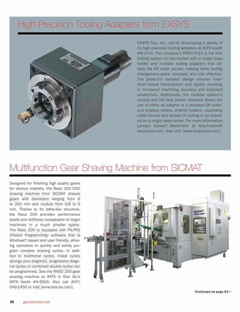
56 gearsolutions.com
EXSYS Tool, Inc., will be showcasing a variety of its high precision tooling adapters at IMTS booth #W-1474. The company’s PRECI-FLEX is the first tooling system on the market with a single base holder and multiple tooling adapters that uti-lizes the ER collet pocket, making lathe tooling changeovers quick, accurate, and cost effective. The product’s compact design ensures maxi-mum torque transmission and rigidity, resulting in increased machining accuracy and improved productivity. Additionally, the modular system’s conical and flat face planar interface allows the use of either an adapter or a standard ER collet, and enables collets, endmill holders, expanding collet chucks and shrinks fit tooling to be mount-ed on a single base holder. For more information contact Stewart Bachmann at [email protected]. Also visit [www.exsys-tool.com].
High Precision tooling Adapters from eXSYS
multifunction Gear Shaving machine from SICmAt
Designed for finishing high quality gears for various markets, the Raso 200 CNC shaving machine from SICMAT shaves gears with diameters ranging from 6 to 200 mm and module from 0,8 to 5 mm. Thanks to its lathe-like structure, the Raso 200 provides performance levels and stiffness comparable to larger machines in a much smaller space. The Raso 200 is equipped with PILPRO (Piloted Programming) software that is Windows®-based and user friendly, allow-ing operators to quickly and safely pro-gram complex shaving cycles. In addi-tion to traditional cycles, mixed cycles (plunge plus diagonal), progressive diago-nal cycles or combined double cycles can be programmed. See the RASO 200 gear shaving machine at IMTS in Star SU’s IMTS booth #N-6924. Also call (847) 649-1450 or visit [www.star-su.com].
Continued on page 62 >

JULY 2010 57
GeAr ACCeSSorIeS, PArTS & TooLInG
FELLOWS Model #10-4/10-2, All Parts Available REF#102Tilt Tables for 10-2/10-4, Qty 2 REF#102FELLOWS Parts Available For All Models REF#103BARBER-COLMAN – PARTS AVAILABLE FOR ALL MODELS REF#103 G&E – PARTS AVAILABLE FOR ALL MODELS REF#103
GeAr hobberS/CuTTerS CnC
LIEBHERR #LC-255 CNC, 6-Axis, 10” Dia, 10” Face, 4 DP, ‘87 REF#103PFAUTER #PE-150, 6-Axis CNC, 6” Dia, 5 DP, 6” Face, Fanuc 18MI REF#103SYKES #H160, 4-Axis CNC Hobber, 6” Dia, All the Features, ‘93 REF#103G&E #60 S-2 CNC Gasher/Hobber REF#103G&E #60SB-2C CNC, Gasher/Hobber REF#103BARBER-COLMAN #16-36, 16” Dia, 4-Axis, 6 DP, 36” Face REF#103LIEBHERR #LC-502 6-Axis CNC Gear Hobber, 20" Diam. Cap., Loading REF#103LIEBHERR #L-652, 5-Axis 26” Dia,27” Face, 2 DP ‘09 REF#103MUIR CNC Gear Hobber, 4-Axis, 118” Dia REF#103LIEBHERR #L-252 3-Axis, 9.8” Dia, recontrolled 2008 REF#103LIEBHERR #ET-1202 CNC - 70” Dia Internal, Single REF#103LIEBHERR #ET-1802 CNC – 98” Dia Internal, 3-Axis REF#103MITSUBISHI GD-20 CNC, 5-Axis, 8” Dia REF#103G&E 120/188, CNC Gasher/Hobber, 188” Dia (5 Meter) REF#103G&E #120GH, CNC, Gasher/Hobber, Twin Stanchion, 1/2 DP, 42” Face, ‘94 REF#103PFAUTER P400H, 5-Axis, 18” Dia, 1 DP, Recontrolled ‘03 REF#103G&E #160GH, CNC, Gasher/Hobber, New ‘07 REF#103G&E #96GH, CNC, Gasher/Hobber, New ‘09 REF#103HAMAI 60SP, CNC 4-Axis, 3.5" OD, 9" Face, 12 DP, New ‘89 REF#103PFAUTER PE 300 AW CNC 6-Axis REF#103
GeAr hobberS/CuTTerS
PFAUTER P1251 Hobbers s/n 25-276 and 25-277 REF#102PFAUTER (1) RS-00 s/n 17593 REF#102BARBER COLEMAN (1) 16-36 multi cycle s/n 4404 REF#102BARBER-COLMAN #16-16, Multi-Cycle, Dual Thread Worm and/or Single Thread Worm REF#103G&E #48H 48” Dia, 18” Face 2 DP, Universal REF#103G&E #48H, 48” Dia, 35” Face, 3 DP, Gooseneck Attachment REF#103LEES BRADNER HH-144 16” Dia, 144” REF#103BARBER-COLMAN #6-16, 6 Multi-Cycle REF#103G&E #36H Differential, Excellent Condition REF#103BARBER-COLMAN #14-30, 14” Dia, 30” Face, 3.5DP REF#103PFAUTER P-251 10” Dia, 9.6” Face, 4 DP REF#103BARBER-COLMAN #14-15, 14” Dia, 15” Face, 1 to 4 Start Worm, Several REF#103BARBER-COLMAN #16-16, 16” Dia, 16” Face, 6DP REF#103
BARBER-COLMAN #16-36, 24” Dia, C-Frame Style, 4 1/8” Bore REF#103BARBER-COLMAN #16-56, 16” Dia, 56” Face, Differential REF#103BARBER-COLMAN #22-15, 22” Dia, 14” Face, Differential REF#103DAVID BROWN, 138” Dia, Face 60”REF#103 G&E #24H Universal Head, Infeed, Tailstock, Differential, ‘50’s REF#103HAMAI #120, 4.8” Dia, 4” Face, 12 DP, ‘70 REF#103LIEBHERR #L-402, 16” Cap, 2-Cut Cycle, Crowning, ‘77 REF#103LIEBHERR #L-650, 26" Dia Cap, 14.5" Face, 2.5 DP, New ‘70’s REF#103MODUL #ZFZW 800, 29.8” Dia, 16.25” Face, 2.5 DP Crowing, 2-Cut REF#103BARBER-COLMAN #1600-36, 16" Dia., 39.5" Face, 6 DP REF#103CHONG QIN #Y3180H, 31.5 Dia., 15" Face, 3 DP REF#103FELLOWS FH-200 Max Diam 7.87" Max Dia Pitch 5.08" REF#103G&E #16H Gear Hobber, 16"Dia REF#103BARBER-COLMAN #3 (6-10), Single & Triple Tread Worm HS REF#103BARBER-COLMAN #6-10, 6” Dia, 10” Face, 16 DP REF#103KOEPFER #140 , 2.75” DIa, 4” Face REF#103 KOEPFER #153B, 5.6” Dia, 5.9” Face REF#103LANSING #GH-50, 50” Dia, 17.75” Face, 2 DP REF#103LIEBHERR #L-252, 9.8” Dia, 7.9” Face, 4.2 DP REF#103MIKRON #79 1.5 Dia, 26 DP REF#103BARBER-COLMAN TYPE T REF#103IUG –Craiova FD-3600 REF#103LIEBHERR #L-401, 15.7” Dia 11” Face, 3DP REF#103G&E #36HS 36”Dia, 14” Face 3 DP REF#103PFAUTER #P-3000, 120” Dia, Single Index REF#103SCHIESS RFW-10-S 55” Dia REF#103SHIBURA HHC-250A Single Index REF#103OVERTON #HD-400, 15.7” Dia, 12” Face, 3 DP, New ‘88 REF#103SCHIESS 1 RF-10, Dia 60” 150” L, .50 DP REF#103G&E #40TWG, 48” Dia, 18” Face, 3 DP REF#103G&E #60S, 72” Dia, 14” Face, 1.25 DP REF#103G&E #72H, 72” Dia, 24” Face, 1 DP REF#103 G&E #96H, 104” Dia, .50 Face, 1.25 DP REF#103PFAUTER #P-630, 25” Dia REF#103 PFAUTER #2500, 100” Dia REF#103TOS FO-16, Max Cut w/support 90” REF#103PFAUTER P250 10” Dia REF#103GE Hobber 200” Dia, 55” Face REF#103GE/Fitchburg Hobber 32” Dia, 72” Face 1.25DP REF#103JF Reinecker 40” Dia 35” Face REF#103LIEBHERR L-160-R 6.5” Dia REF#103MIKRON #102.04 , 4’ Dia, 5” Face REF#103NIHON-Kikai NDH-1200 50” Dia REF#103PFAUTER P-900 36” Dia REF#103SCHIESS RF 40/60S 240” Dia 100” Face REF#103BARBER-COLMAN #25-15 25” Dia, 15” Face, 2.5 DP REF#103CRAVEN Horizontal , 18” Dia and 100” Length REF#103KOEPFER #173B, .6.1” Dia, 7” Face REF#103PFAUTER #P-630R, 25" Max. Spur Dia, 12" Max Rotor Dia. 12" REF#103BARBER-COLMAN 2 1/2 -4, S/N 119, ’62 Hi-Production Spur Gear REF#104BARBER-COLMAN 6-10 SYKES, Triple Thrd w/Lever Operated Collet Assy REF#104BARBER-COLMAN 6-10 B&C Ltd, S/N 8079, Triple Thrd REF#104BARBER-COLMAN 6-10, S/N 4626, ’57 Triple Thrd 3” Hob Slide REF#104BARBER-COLMAN 6-10, S/N 4659R, ’56 Triple Thrd Adj Ctr Assy REF#104BARBER-COLMAN 6-10, S/N 4665, ’57 Fine Pitch Prec Triple Thrd REF#104BARBER-COLMAN 6-10, S/N 4701, ’58 Triple Thrd w/Power Down Feed REF#104BARBER-COLMAN 6-10 M/C, S/N 4755, ’59 Triple Thrd w/MC Conversion REF#104BARBER-COLMAN 6-10 Multicycle, S/N 4778R87, ’60 (’87 Rebuild), Sgl Thrd Hi-Spd REF#104BARBER-COLMAN 6-10 M/C, S/N 4913, ’63 Triple Thrd w/90 Deg Hob Slide REF#104BARBER-COLMAN 6-10 Multicycle, S/N 5055, ’66 Triple Thrd, 800 RPM REF#104BARBER-COLMAN 6-10, S/N 5141, ’67 Triple Thrd w/Prec Hob Shift REF#104BARBER-COLMAN 6-10 Multicycle, S/N 5148, ’68 Triple Thrd, 800 RPM REF#104BARBER-COLMAN 6-10 Multicycle, S/N 5259, ’75 Triple Thrd w/Auto Hob Shift REF#104BARBER-COLMAN 6-10, S/N 5353, ’77 Triple Thrd w/3” Hob Slide, 800 RPM REF#104BARBER-COLMAN 6-10, S/N 5394, ’81 Fine Pitch Triple Thrd w/Dwell & Hob Rev REF#104BARBER-COLMAN 6-16 M/C, S/N 5238, ’70 Triple Thrd, Recon ‘02 REF#104
BARBER-COLMAN 6-10, S/N 5407, ’82 Auto w/PLC Control REF#104BARBER-COLMAN DHM, S/N 105, ’42 Double Thrd REF#104BARBER-COLMAN 14-15, S/N 635R, ’53 Dbl Thrd, Fact Reb REF#104BARBER-COLMAN 14-15, S/N 745, ’55 Dbl Thrd w/Dwell REF#104BARBER-COLMAN 14-15 Dual Fd, S/N 938, ’62 Dbl Thrd, Comp Reco REF#104BARBER-COLMAN 14-15, S/N 1055, ’65 Dbl Thrd w/New Hyd Sys REF#104BARBER-COLMAN 14-15, S/N 1131, ’66 Dbl Thrd w/Hyd Tailctr REF#104BARBER-COLMAN 14-15 Dual Fd, S/N 1261, ’67 Dbl Thrd w/Hyd Live Ctr REF#104BARBER-COLMAN 14-15 Dbl Cut, S/N 1278, ’68 Dbl Thrd w/4-1/8” Bore REF#104BARBER-COLMAN 14-30 Dual Fd, S/N 1371, ’71 4-Thrd w/Sizing Cycle REF#104BARBER-COLMAN 22-15, S/N 923, ’62 Dbl Thrd, Dbl Cut REF#104BARBER-COLMAN 16-11, S/N 184, ’50 Dbl Thrd w/Vert DRO REF#104BARBER-COLMAN AHM, S/N 1896, ’42 Sgl Thrd w/3 Jaw Chuck REF#104BARBER-COLMAN 16-16, S/N 2745, ’51 Sgl Thrd w/90 Deg Hd REF#104BARBER-COLMAN 16-16, S/N 3171, ’53 Dbl Thrd, Spanish Nameplates REF#104BARBER-COLMAN 16-16, S/N 3580, ’59 Dbl Thrd w/Diff & Auto Hobshift REF#104BARBER-COLMAN 16-16 Multicycle, S/N 3641, ’60 Dbl Thrd w/Diff REF#104BARBER-COLMAN 16-16, S/N 3660, ’57 Sgl Thrd REF#104BARBER-COLMAN 16-16, S/N 4136, Dbl Thrd, “C” Style End Brace w/Diff REF#104BARBER-COLMAN 16-16 Multicycle, S/N 4170, Dbl Thrd w/Jump Cut Cycle “C” Style REF#104BARBER-COLMAN 16-16, S/N 4473, ’73 4-Thrd w/Workclamp Cyl “C” Style REF#104BARBER-COLMAN 16-16 Multicycle, S/N 4520, ’75 Dbl Thrd w/Gooseneck Slide REF#104BARBER-COLMAN 16-16 Multicycle, S/N 4631, ’79 “C” Style End Brace, 4W Adj Ctr REF#104BARBER-COLMAN AHM (36”), S/N 1152, ’42 Dbl Thrd REF#104BARBER-COLMAN 16-36, S/N 4090, ’66 Dbl Thrd, “C” Style End Brace REF#104BARBER-COLMAN 16-36 Multicycle, S/N 4232, ’68 Dbl Thrd “C” Style End Brace w/Diff REF#104BARBER-COLMAN 16-56, S/N 3136R84, ’53 (Reb ’84), Dbl Thrd REF#104BARBER-COLMAN 10-20, S/N 6700045890, ’76 Dbl Thrd w/2 Cut Cycle REF#104TOS OFA Series Conventional Gear Hobbers, 12” & 40” Dia REF#105TOS OHA Series Conventional Gear Shapers, 12” & 40” Dia REF#10516-16 Barbara Coleman with differential yr 1970 id 3535 REF#106Jeil model JDP-2 26” dia. Diff & infeed OB Yr1990 ID 3570 REF#106Fitchburg spline & pinion 32” OD, 72” REF#106Liebherr L-301, 12” dia. Yr 1974 id 3465 REF#106
GeAr PInIon hobberS & SPLIne mILLerS
HURTH #KF-32A 15” Dia, 59” Face, ‘67 REF#103GE/Fitchuburg Pinion Hob 32” Dia, 72” Face REF#103MICHIGAN Tool #3237 REF#103SCHIESS 1 RF-10, 60” Dia REF#103WANDERER GF 345 CNC Hobbing /Milling Machine 4-Axis 24" Swing x 240” Length REF#103FITCHBURG Pinion Hobber 42” Dia, 72” Dia REF#103CRAVEN Horizontal, 18” Dia and 100” Length REF#103
GeAr hob & CuTTer ShArPenerS (incl CnC)
ARTER #A-12, 12” Rotary Surface Grinder for Sharpening Sharper Cutters REF#103BARBER-COLMAN #6-5, 6" Dia, 5" Length, Manual Dresser, ‘57 REF#103BARBER-COLMAN 10-12, 10" Dia, 12" Length, Spark Out REF#103FELLOWS #6SB, Helical Cutter Sharpener, 6” Dia, up to 50 Degrees REF#103KAPP #AS-305GT, 1 DP, 28" Grind Length, 10" Diam., Str. & Spiral REF#103KAPP #AS204GT, 10” Dia, Wet Grinding, CBN Wheels, ‘82 REF#103BARBER-COLMAN #3 HS, Hob Sharpener, 4" Max. OD., 4" REF#103BARBER-COLMAN #4-4HRS, Hob Sharpener, 4" Max. OD. 4" REF#103REDRING MODEL #SGH "PREIFORM" SHAVE CUTTER GRINDER/SHARPENER REF#103STAR 6X8 HOB SHARPENER PRECISION GEAR & SPLINE HOBBER REF#103BARBER-COLMAN 2-2 1/2 , 2.5” Dia REF#103KAPP #AST-305B, 27.5” Dia, REF#103KAPP AS-410B REF#103
FEATUREDSUpplierSMidwest gear Corporation — reF #101Phone: 330-425-4419 • Fax: 330-425-8600email: [email protected]: www.mwgear.com
new england gear — reF #102Phone: 860-223-7778 • Fax #:860-223-7776email: [email protected]: www.newenglandgear.com
r. P. Machine enterprises, inc. — reF #103Phone: 704-872-8888 • Fax #:704-872-5777email: [email protected]: www.rpmachine.com
repair Parts, inc. — reF #104Phone: 815-968-4499 • Fax #:815-968-4694email: [email protected] Website: www.repair-parts-inc.com
Havlik international Machinery, inc. — reF #105Phone: 519-624-2100 • Fax: 519-624-6994email: [email protected]: www.havlikinternational.com
gQ Machinery inc.— reF #106Phone: 516.867.4040 • Fax: 516.223.1195email: [email protected]: www.gqmachinery.com
mAChInerYContact Gear Solutions at
800-366-2185 to list your machinery.

58 gearsolutions.com
GLEASON #12 Sharpener, 3-18” Cone REF#103BARBER-COLMAN 2 1/2-2, S/N 16, ’66 Wet w/Auto Feed REF#104BARBER-COLMAN 6-5, S/N 110R, ’55 Wet w/Auto Dress & Sparkout REF#104BARBER-COLMAN 6-5, S/N 396, ’66 Wet w/Auto Dress & Sparkout REF#104BARBER-COLMAN 6-5, S/N 433, ’69 Wet w/Auto Dress & Sparkout REF#104BARBER-COLMAN 10-12, S/N 643R83, Wet w/Auto Dress, PC Control, Fact Reb ‘83 REF#104TOS OHA Series CNC Gear Shapers, 12” & 40” Diameter REF#105 TOS OFA Series CNC Gear Hobbers, 12” & 40” Diameter REF#105
GeAr ShAPerS CnC
36” Shapers, 14” Throat Risers, 53” of Swing, Qty 3 REF#102FELLOWS #10-4/10-2, Qty 150 REF#102HYDROSTROKE #50-8, Qty 2 REF#102HYDROSTROKE #20-8, Qty 5 REF#102HYDROSTROKE #FS630-125, Qty 1 REF#102HYDROSTROKE #FS400-90, Qty 2 REF#102FELLOWS #20-4, Qty 6 REF#102FELLOWS #48-8Z, Qty 1 REF#102FELLOWS #FS-180, 3-5 Axis, 7” Dia, 1.25” Face., 6 DP, New ‘88 REF#103LIEBHERR #WS-1, 4-Axis CNC, 8" OD, 2" Stroke, Fanuc 18MI REF#103LORENZ # LS-180, 4-Axis CNC, 11” OD, 2” Stroke, 5 DP REF#103LORENZ #LS-304 CNC Gear Shaper 5-Axis Heckler & Koch Control REF#103LORENZ #LS-156 CNC Gear Shaper Dia 6” REF#103FELLOWS FS400-125, 16” Dia, 3.5 DP 5” Face REF#103SCHIESS RS-20 S, 12” Stroke, 118” Dia REF#103FELLOWS #10-4 3-Axis (A/B), 10" Dia, 4" Face, 4 DP New .’09 REF#103RP-GS 800 CNC, 4-Axis, Max Dia 31.5”, Face 9”, 2.5 DP REF#103 RP-GS 400 CNC, 6-Axis, Max Dia 15” Face 4”, 3 DP REF#103STANKO /RPM #48-8 Gear Shaper CNC, Fanuc 18 REF#103 FELLOWS #10-4 2-Axis, 10” Dia 4” Face REF#103FELLOWS #20-4 3-Axis 10” Dia, 4” Face REF#103FELLOWS FS400-90 Hydro-stroke Gear Shaper CNC Nominal Pitch 15.7" REF#103RP-GS 1500 CNC, 4-Axis, Max Dia 49.2”, Face 12”, 2 DP REF#103
GeAr ShAPerS
FELLOWS #10-2, (10” Dia), 2” Face REF#102FELLOWS #10-4, (10” Dia), 4” Face REF#102FELLOWS (200) 10-4 / 10-2 Shapers REF#102FELLOWS (1) 50-8 Hydrostroke Shaper s/n 36607 w/ 6 axis 16iMB Fanuc (2009) REF#102FELLOWS (1) 20-8 Hydrostroke Shaper s/n 35932 w/ 6 axis 16iMB Fanuc (2009 REF#102 FELLOWS (1) #7 125A Face Gear Machine REF#102FELLOWS (2) #3 Face Gear Machine REF#102(1) 4ags with adjustable Helical Guide s/n 30634 REF#102(1) #7 125A adjustable Helical Guide REF#102FELLOWS (1) FS630-200 Hydrostroke Shaper s/n 36943 w/ 6 axis 16iMB Fanuc (2009) REF#102FELLOWS (3) Tilt Table 10-4 / 10-2 w/ 4 axis 21i Fanuc Controller (2009) REF#102FELLOWS (2) Swing-away center support for 10-2 / 10-4 REF#102FELLOWS (1) FS630-170 Hydrostroke Shaper s/n 36732 w/ 6 axis 16iMB Fanuc (2009) REF#102FELLOWS (2) FS400-170 Hydrostroke Shaper w/ 6 axis 16iMB Fanuc (2009) REF#102FELLOWS (4) FS400-125 Hydrostroke Shaper w/ 6 axis 16iMB Fanuc (2009) REF#102FELLOWS (1) 20-4 Shaper s/n 35687 w/ 4 axis 21i Fanuc Controller (2009) REF#102FELLOWS (1) 48-8Z Shaper w/ 14” throated riser (53” of swing) REF#102FELLOWS (1) Horizontal Z Shaper s/n 21261 REF#102FELLOWS (1) 4-B Steering Sector Gear Shaper w/ 18iMB 4 axis Fanuc controller s/n 34326 REF#102FELLOWS (1) 36-10 Gear Shaper REF#102FELLOWS (1) 10x6 Horizontal Z Shaper REF#102FELLOWS (1) 36-6 Gear Shaper w/ 13” riser s/n 27364 REF#102FELLOWS (1) 10-4 Shaper w/ 3” riser w/ 4 axis 21i Fanuc Controller (2009) REF#102All Parts for 10-4/10-2 Fellows Gear Shapers REF#102FELLOWS #36-8, 36” Dia, 8” Face REF#103FELLOWS #100-8 100” Dia, 8” Face REF#103FELLOWS #612A, 615A, #645A REF#103FELLOWS #10-4, 10” Dia, 4” Face, 4 DP REF#103FELLOWS #4A Versa, 10” Dia, 3” Face, 4 DP, New ‘70’s REF#103FELLOWS #10-2, 10” Dia, 4” Face, 4 DP REF#103FELLOWS #20-4, 20” Dia, 4” Face, 4 DP, ‘70’s REF#103MAAG #SH-100/140, 57” Dia., 12.6” Face, 2 DP, Internal Attachment REF#103FELLOWS #3-1,/3GS, 3” Max Dia, 1” Face, Pinion Supp, High Precision REF#103FELLOWS #48-6 INTERNAL GEAR SHAPER ONLY,0-72"OD,6" Face REF#103LORENZ #SJV00, 7” Dia, 2” Face, ‘50’s REF#103MAAG #SH-100K 47”/12.6”/1.7 ‘60’s Internal Attachment REF#103
MAAG #SH-150, 57" Dia.12.6" Face REF#103PFAUTER #SH-180 Shobber 7" capacity hobbing, 9.45" cap REF#103FELLOWS #36-6 Max Dia 36” 6” Face, 3 DP REF#103FELLOWS #HORZ Z SHAPER, 10 x 6 Dia 27.6 Face 8.5” REF#103MAAG #SH-75C, 30”/8”/2.5”/’52 REF#103MAAG #SH-600, 235” Dia 36”, 1DP REF#103FELLOWS #4GS & 4AGS, 6” Dia, 2” Face, 4DP, ’68, Ref.# Several REF#103TOS OH-6, Dia 19.7” REF#103FELLOWS #624A, 18” Max Dia, 5” Face REF#103FELLOWS #7, #7A, #715,# 75A, #715, #725A, 7” Dia, 0-12” Risers, Several Avail REF#103MAAG #SH-180-300 , Max Dia 118”/ 16.9” Face REF#103MAAG #SH-350/500, Max Dia 197” REF#103MICHIGAN #18106 SHEAR-SPEED GEAR SHAPER,14" Dia, 6"Face REF#103FELLOWS Model Z Shaper, 5" Stroke, ‘50’s REF#103STAEHELY SHS-605, Gear Shaper REF#103FELLOWS #6, #6A, #61S, From 18”-35” Dia, 0-12” Risers REF#103FELLOWS #8AGS Vertical Gear Shaper, 8” Dia, 2” Face, 6-7 DP REF#103TOS OHA50 CNC 5 20” Dia 5” Face REF#10536-8 Fellows 9” stroke 12” Riser mint yr 1970 REF#106
GeAr DeburrInG/ChAmFerInG/PoInTInG
CROSS #50 Gear Tooth Chamferer, 18” Dia, Single Spindle REF#103CROSS #75 Gear Tooth Chamferer, 10” Dia, 10” Face, ‘52 REF#103REDIN #18, 28” Dia, 2, 3, 4 Spindle, Deburrer/Chamfer, PLC’s, Tilt Table REF#103REDIN #20D, 20” Dia, Twin Spindle, Deburrer/Chamfer REF#103SAMPUTENSILI #SCT-3, Chamf/Deburrer, 14” Dia, 5” Face, ‘82 REF#103SAMPUTENSILI #SM2TA Gear Chamfering Mach, 10” Max Dia, (3) New ‘96 REF#103REDIN #24 CNC Dia 4” Setup Gear Deburring REF#103 CROSS #60 Gear Tooth Chamferer, 10” Dia, Single Spindle REF#103FELLOWS #100-180/60 CNC Max Dia 180”, Single Spindle REF#103CIMTEC #50 Finisher REF#103RPM #GC-500 CNC 20” Dia, Single Spindle REF#103CROSS #54 Gear Deburrer, 30” Dia, 18” Face REF#103RED RING #24 Twin Spindle Dia 4” REF#103CROSS #55 Gear Deburrer, 18” Dia, 1.5 Spindle REF#103GLEASON GTR-250 VG CNC 5-Axis REF#103GRATOMAT #300L REF#103
GeAr honerS
Fassler #K-400 CNC Hone 16" Dia REF#103Fassler K-400A CNC Hone 16” Dia REF#103Kapp #CX120 Coroning 4.7” Dia REF#103Red Ring GHD-12, 12” Dia, 5.5 Stroke REF#103 Red Ring GHG, 12” Dia, 5.5 Stroke REF#103 Kapp #VAC65 Coroning 10” Dia REF#103
GeAr ShAVerS
Red Ring #GCX-24" Shaver, 24” Dia, 33” Stroke REF#103Red Ring #GCU-12, 12” Dia, 5” Stroke REF#103 Red Ring #GCU-8 Shaver. 8” Dia REF#103Red Ring #GCY-12, 12” Dia, 5” Stroke REF#103 Red Ring GCI 24, 12.75” Dia, 5” Stroke REF#103Nachi Raso CNC Shaver, 3-Axis REF#103Michigan #873-24A, 24” Dia, 15” Face, 2 DP REF#103
GeAr GenerATorS, STrAIGhT beVeL
GLEASON #37 Str. Bevel Planer, 6” Dia REF#103GLEASON #54 Str, Bevel Planer, 60” Dia REF#103GLEASON #496 Straight.& Spiral. 7.5” Dia REF#103GLEASON 14, Coniflex Straight Bevel REF#103GLEASON 24A Straight Bevel REF#103GLEASON 725-Revacycle, 6” Dia REF#103GLEASON 726-Revacycle, 5” Dia REF#103GLEASON 2A, 16” Cone REF#103GLEASON #116, 9” Cone, 2.75 Face REF#103GLEASON #104 w/Helical Motion, Coniflex, Straight Bevel REF#103
GeAr GenerATorS, SPIrAL beVeL (hYPoID)
GLEASON #645 Hypoid Generators REF#103
GeAr GrInDerS CnC
HOGLUND, Model #264, CNC Internal Gear Grinder REF#103KAPP #VAS-482 CNC GEAR GRINDER, 11.8" SWING DIA REF#103GLEASON Phoenix 200G Hypoid Grinder CNC REF#103REISHAUER RZ-801 CNC, 31.4” Dia REF#103NILES ZSTZ 06-800 CNC, 31.5” Dia, 11” Face REF#103NILES ZSTZ 08-800 CNC, 32” Dia, 11” Face REF#103
RED RING #SF-500 CNC Int/Ext, 26” Dia, REF#103 GLEASON/TAG – 400 CNC, 16” Dia REF#103HOLFER PROMAT 200 , 7.87” Dia CNC Gear Grinder REF#103
GeAr GrInDerS
#27, #137, and #463 Gleason Hypoid Spiral Bevel gear grinder generating Cams (2 full sets) REF#102Springfield Vertical Grinder, 62" Table, #62AR/2CS, 3.5A Rail Type, 70" Swing REF#102REISHAUER ZA, Gear Grinder, 13" Dia, 6" Face, Strait & Helix REF#103RED RING #SGJ-18, 18” Dia., 9” Face, Internal Attachment, New ‘78 REF#103DETROIT Gear Grinder #GGI-16x3A, Internal Gear Grinding, 16" OD REF#103MAAG SD-32-X REF#103GLEASON #463, 15” Dia REF#103HOFLER BHS H1603-2000, 78.7” Dia REF#103NILES ZSZT-3500, 139” Dia REF#103KAPP VAS #331, Gear Grinder REF#103NILES ZSTZ-1250/5000 49.2Dia REF#103
GeAr rACK mILLerS/ShAPerS
MIKRON #134 Rack Shaper, 17.4" Length, 1.1" Width, 16.9 DP REF#103SYKES VR-72 Vert Rack Shaper, 72" Cut Length, 4DP, 4" Stroke, ‘80 REF#103SYKES VR-60 Vert Rack Shaper, 60” Cut Length, 4DP, Stroke 4” REF#103
GeAr ThreAD & Worm, mILLerS/GrInDerS LEES BRADNER #HT 12x54, Dia 12” /54” REF#103MOREY-SHIELDS THREAD MILLER, Dia 12” REF#103BARBER-COLMAN #10-40, 10" Dia., 40" Length, 4 DP REF#103EXCELLO #31L, External Thread Grinder, 5" OD, 20" Grind Length REF#103EXCELLO #33 Thread Grinder 6” Dia 18” Length REF#103EXCELLO #35 and #35L Thread Grinder, 84" Between Centers REF#103EXCELLO #39 Int. Thread Grinder, 9.5" Max Dia., 10" Max. Swing REF#103HURTH #KF-33A Multi-Purpose Auto-Milling Machine 88” REF#103LEES BRADNER #HT12x102, Extra Large Capacity REF#103J&L AUTOMATIC THREAD GRINDER, 6" X 36", ‘38 REF#103LEES BRADNER #HT 12"x 144" Thread Mill, 12" Dia, REF#103 WALDRICH COBURG WHIRLING, 3” Dia, 118” Length REF#103 LEES BRADNER # LT 8” x 24” 8” Dia REF#103 HOLROYD 5A 24.8 “ Dia REF#103 HECKERT WMW #ZFWVG REF#103 LEES BRADBER WORM MILLER REF#103
GeAr TeSTerS/CheCKerS (incl CnC)
FELLOWS (1) RL-600 Roll Tester s/n 35814 REF#102FELLOWS (1) 24H Lead Checker s/n 32289 REF#102GLEASON (1) #14 Tester s/n 31907 REF#102GLEASON (1) #6 Tester s/n 19316 REF#102FELLOWS (1) 20 M Roller Checker REF#102FELLOWS (1) 20 M w/ 30” Swing Roller Checker REF#102FELLOWS (1) #8 Micaodex s/n 36279 REF#102David Brown #24 Worm Tester REF#103Fellows 12H Gear Tester REF#103Fellows #12M Gear Tester REF#103Fellows 20M Gear Tester REF#103Felows #24 Involute Measuring Instrument REF#103Gleason #4, #6, #13 and #17 Testers REF#103Hofler EMZ-2602 Int/Ext Gear Tester 102” REF#103Klingelnberg #PFSU-1200 Gear Tester REF#103Klingelnberg #PFSU-1600 Gear Tester-2001 REF#103Klingelnberg PWF-250 Tester REF#103Kapp Hob Checker WM 410 REF#103Maag #ES-430 Gear Tester REF#103Maag #SP-130 Lead and Involute Tester REF#103National Broach Gear Tester GSJ-12 REF#103Oerlikon #ST2-004 Soft Tester REF#103Maag #SP-60- Electronic Tester REF#103Parkson #42N Worm Gear Tester REF#103Fellows #24H Tester REF#103Gleason #104 Tester REF#103Vinco Dividing Head Optical Inspection REF#103
mISCeLLAneouS
WARNER & SWAYSEY #4A M-3580 Turret Lathe, 28 1/4 Swing, 80” Centers, 12” Spindle Hole 50/25 Motors, 480/3 Phase, Year 1965 REF#101Springfield Vertical Grinder, 62" Table, #62AR/2CS, 3.5A Rail Type, 70" Swing REF#102GLEASON #529 Quench, 16" Diameter REF#103VERTICAL TURNING LATHES AND MORE - Please Check Our Website To View Our Entire Inventory REF#103TOS SU & SUS Series Conv Lathes REF#105TOS SUA Series CNC Flat-Bed Lathes REF#105


60 gearsolutions.com
GEAR GRINDING SERVICESGear cutting from raw material to finished parts
Ground tooth gears and pinions to 1 D.P. and up to AGMA quality class 13
From 1” Diameter, 64 D.P. to maximum sizes listed Max. Face Max. Size Max. Pitchspur Gears 24” 92” P.d. 1 d.P.
helical Gears 24” 72” P.d. 1 d.P.
spur & helical Gears, crown hobbed 22” 72” P.d. 1 d.P.
internal Gears & splines 8” 100” P.d. 1-1/4 d.P.
Ground Gears, crowned or straight 20.5” 72” P.d. 1 d.P.
herringbone Gears, center Grove 14” 36” P.d. 2 d.P.
2182 E. Aurora Rd., Twinsburg, OH 44087Phone: (330) 425-4419 • Fax: (330) 425-8600
www.mwgear.com • E-mail: [email protected]
We Manufacture Broaches & related
tooling for any Broach Machine
Broach houseMfg., inc.™We Have Used Broaches In Stock
11383 Route 166 • Marion, Il 62959618-993-3530 • Fax:618-997-9158e-mail: [email protected]
Sharpening or reconditioning alSo production Broaching
We Weld Broken & Chipped Broaches
HOB SHARPENING(763) 425-5247
★ THIN FILM COATINGS ★hss & carbide up to 5” dia.
straight Gash,sharpened & inspectedPer aGMa standaRdsQuick Turnaround
KORO SHARPENING SERVICE9530 85th aVenue noRthMaPle GRoVe, Mn 55369

JULY 2010 61
manufacturing excellencethrough quality, integration, materials, maintenance, education, and speed.
mArKetPLACE
technical solutions
aerospace and automotive applications
Hermes Abrasives, Ltd.524 Viking drive • Virginia beach, Va 23452 toll free phone: 800.464.8314Po box 2389 • Virginia beach, Va 23450 toll free fax: 800.243.7637
Multiple start GearGrinding Wheels
• lower grinding forces• new abrasive blends & bonds• lower grinding temperatures• increased porosity for higher
stock removal
Gear honing benefits
• Flank correction• Reduced operating noise• longer service life• correction for distortion from harden-
ing process
Gear Hobbing, Sharpening, and roll Testing machines – rebuilds / retrofits and Spare parts Services
Need spare parts and machine services for your obsolete MIKRON Model 132, 102, A33, or A21 gear hobbers, or A60 Hob Sharpener, or 1R, 2R, 3R Gear Roll Testers?
• Machine trade-in and re-build services• Spare Parts & New Replacement parts for:
Hobbing Spindles ∅8.0 or 10mm, Hob Cutters, Hob Arbors, Centers, Work-holding Collets, Geared Drives, Motors, Change Gears and Phenolic Gears
• Electronics & Controls upgrades & Retrofits: Drive motors, PLC and solid state electronics only –or- new PC based Controller and Servo Drives
• New Rigid High Speed CNC gear hobbers – to cut gears and splines up to 50mm / 2” & 100mm/ 4 “ OD’s, up to 16,000 rpm hob spindle & 5,000 rpm work spindle speeds: ideal for dry Carbide hob cutting.
• Replacement parts for Model 1R & 2R gear roll testers, arbors, master gears or NEW granite bed gear roll tester with WinGear (r) PC based gear roll test controller and analysis software.
For prices and deliveries today Call 1-877-567- GAGE (4243) or email: [email protected]
STOR-LOC MODULAR DRAWER SYSTEM880 N. Washington Ave. Kankakee, IL 60901
Toll Free: 1.800.786.7562 • Fax: 1.800.315.8769email: [email protected]
www.storloc.com
For your MAstEr GEAr & splinE GAGinG nEEds
Call 1-877-567-GaGe (4243) or email: [email protected]
parKer industries incorporated1650 sycamore avenue bohemia, nY 11716tOll Free 1-877-567-GaGet: 631-567-1000 | F: 631-567-1355 | W: parkerind.com
• GEAR CUTTING TOOLS• SHAPER CUTTERS• HOBS-HSS AND CARBIDE• SPECIAL PURPOSE TOOLS• SPLINE GAGES• BROACHES• THREAD MILLING CUTTERS• SPLINE ARBORS• HELICAL GUIDES FOR GEAR
SHAPING MACHINES
• neW! Tool CoaTings-ChoiCe of sTandard and our proprieTary CoaTings
• neW! Tool sharpening and reCondiTioning
• GEAR ROLL TESTERS wITH WinGear™ pC TEST AND evaluatiOn sOFtWare
• MASTER GEARS

62 gearsolutions.com
New NBV Vertical machining Center from mAG
The new NBV vertical machining cen-
ter is as noteworthy for what it doesn’t
have as what it has. Eliminating all
hydraulics, this compact VMC is flush
with modular application flexibility,
including configurations for three-,
four-, and five-axis contouring or five-
axis mill/turn work, integrated CAM
support and program simulation, and
four spindle options ranging up to
42,000 rpm. In addition to its hydrau-
lic-free design, the NBV conserves
energy with a selectable ECO-Mode
power saving feature that automati-
cally levels speed and acceleration
for an ideal balance of cutting per-
formance, energy use, and machine-
component life. Ideal applications
include die/mold, automotive and
aerospace impellers and blisks, med-
ical, and general machining. Control
options for the NBV 400 include
Siemens, Bosch Rexroth, Fanuc
and Heidenhain. The NBV 400 is a
self-contained unit, making for easy
transportation, rigging and setup.
Automation and other processing
options, including MQL/dry machin-
ing, robot load/unload systems and
additional tool-disc magazines, are
easily integrated. Learn more by visit-
ing IMTS booth # E-5515 or going to
[www.mag-ias.com].
< Continued from page 56
JULY 2010 63
advertiserINDEX
COMPANY NAMe.................... PAGe NO.aLd thermal treatment inc. ...................................................11allen adams shaper services .................................................60aWea .......................................................................................55B&r Machine and Gear Corp .................................................21Beavermatic inc ......................................................................41Bourn & Koch ..........................................................................63Broach House Mfg. inc ...........................................................60Carolina Gear & Components, Ltd ..........................................23Chamfermatic inc ....................................................................29Cincinnati Gearing systems ....................................................37Clifford Jacobs Forging Co .....................................................43dt technologies CZ sro ..........................................................29eldec induction Usa ...............................................................40excel Gear ...............................................................................60Gear Manufacturing inc...................................................... 61,62Gear Motions inc .....................................................................60Gleason Corporation ............................................................. iFCHanik Corporation ...................................................................63High Performance Gear inc .....................................................28iMts 2010 ...............................................................................59Hermes abrasives Ltd. ............................................................61innovative rack & Gear Co .....................................................60J L Becker Co .........................................................................40Kisssoft Usa LLC ..................................................................46Klingelnberg GmbH ...................................................................2Koro sharpening service ........................................................60Loudon industries inc ..............................................................51MicroGear................................................................................14Midwest Gear Corp .................................................................60Mitsubishi Heavy industries america inc ...............................BCMound tool Co ........................................................................46National Bronze & Metals inc ..................................................49New england Gear ....................................................................7Overton Chicago Gear ............................................................13P&G Machine & supply Co inc ...............................................61Parker industries .....................................................................61Process equipment Company ................................................10Proto Manufacturing Ltd .........................................................12r P Machine enterprises inc ..............................................32-33raycar Gear & Machine Co.....................................................50repair Parts inc .......................................................................51riverside spline and Gear inc ..............................................9,31sakuni Usa .............................................................................60sandvick Coromant ...............................................................iBCsolar atmospheres ..................................................................45stor-Loc ..............................................................................52,61surface Combustion ...............................................................19the Broach Masters ..................................................................4the Cincinnati steel treating Co ............................................44the Company Corporation ......................................................60tMFM LLC ..............................................................................50toolink engineering ...................................................................1Walker Forge inc .....................................................................44Willman industries ...................................................................49
www.hanikcorp.com
CORPORATION
t
Booth# N6924
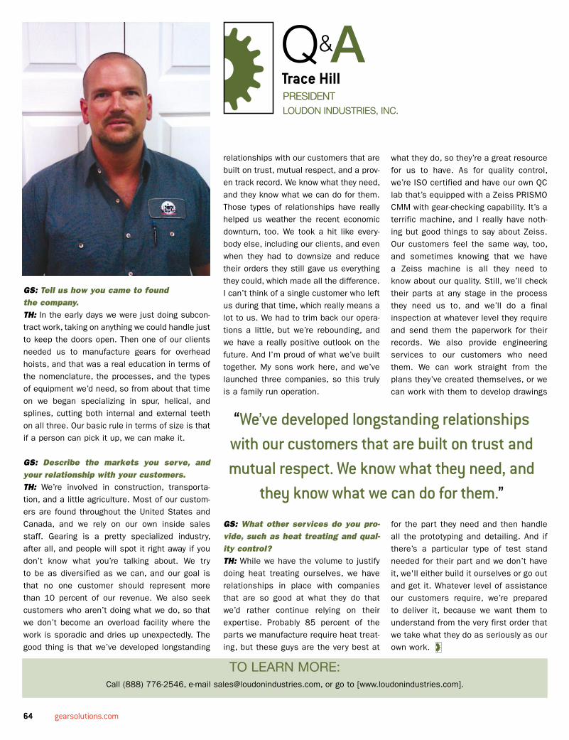
64 gearsolutions.com
GS: Tell us how you came to found the company.TH: In the early days we were just doing subcon-tract work, taking on anything we could handle just to keep the doors open. Then one of our clients needed us to manufacture gears for overhead hoists, and that was a real education in terms of the nomenclature, the processes, and the types of equipment we’d need, so from about that time on we began specializing in spur, helical, and splines, cutting both internal and external teeth on all three. Our basic rule in terms of size is that if a person can pick it up, we can make it.
GS: Describe the markets you serve, and your relationship with your customers. TH: We’re involved in construction, transporta-tion, and a little agriculture. Most of our custom-ers are found throughout the United States and Canada, and we rely on our own inside sales staff. Gearing is a pretty specialized industry, after all, and people will spot it right away if you don’t know what you’re talking about. We try to be as diversified as we can, and our goal is that no one customer should represent more than 10 percent of our revenue. We also seek customers who aren’t doing what we do, so that we don’t become an overload facility where the work is sporadic and dries up unexpectedly. The good thing is that we’ve developed longstanding
PREsIDENTLOuDON INDusTRIEs, INC.
trace hillQ&a
TO LEARN MORE:Call (888) 776-2546, e-mail [email protected], or go to [www.loudonindustries.com].
relationships with our customers that are built on trust, mutual respect, and a prov-en track record. We know what they need, and they know what we can do for them. Those types of relationships have really helped us weather the recent economic downturn, too. We took a hit like every-body else, including our clients, and even when they had to downsize and reduce their orders they still gave us everything they could, which made all the difference. I can’t think of a single customer who left us during that time, which really means a lot to us. We had to trim back our opera-tions a little, but we’re rebounding, and we have a really positive outlook on the future. And I’m proud of what we’ve built together. My sons work here, and we’ve launched three companies, so this truly is a family run operation.
GS: What other services do you pro-vide, such as heat treating and qual-ity control?TH: While we have the volume to justify doing heat treating ourselves, we have relationships in place with companies that are so good at what they do that we’d rather continue relying on their expertise. Probably 85 percent of the parts we manufacture require heat treat-ing, but these guys are the very best at
what they do, so they’re a great resource for us to have. As for quality control, we’re ISO certified and have our own QC lab that’s equipped with a Zeiss PRISMO CMM with gear-checking capability. It’s a terrific machine, and I really have noth-ing but good things to say about Zeiss. Our customers feel the same way, too, and sometimes knowing that we have a Zeiss machine is all they need to know about our quality. Still, we’ll check their parts at any stage in the process they need us to, and we’ll do a final inspection at whatever level they require and send them the paperwork for their records. We also provide engineering services to our customers who need them. We can work straight from the plans they’ve created themselves, or we can work with them to develop drawings
for the part they need and then handle all the prototyping and detailing. And if there’s a particular type of test stand needed for their part and we don’t have it, we'll either build it ourselves or go out and get it. Whatever level of assistance our customers require, we’re prepared to deliver it, because we want them to understand from the very first order that we take what they do as seriously as our own work.
“We’ve developed longstanding relationships with our customers that are built on trust and mutual respect. We know what they need, and
they know what we can do for them.”

