070506 final report milinichik cynthia comcast · ae 482 comcast center cynthia milinichik advisor:...
TRANSCRIPT

Page 1 of 84
FINAL REPORT
A. EXECUTIVE SUMMARY
A.1 BUILDING DESCRIPTION
The Comcast Center is located in downtown Philadelphia, Pennsylvania on John F. Kennedy Boulevard and 17th Street. The 57 story building functions primarily as office space with some retail and restaurant spaces. The structural system consists of a massive concrete core with steel members framing into the core. The floor system is a composite metal deck. The footprint of the Comcast Center tower is approximately 195 feet by 135 feet.
A.2 STRUCTURAL DEPTH SUMMARY
The existing 6 web concrete core can be reduced to a 4 web core and still meet serviceability criteria. Reducing the size of the concrete core introduces several areas of flexibility into the architecture. Three levels of below grade parking will benefit with extra spaces for parking. The mechanical system spaces originally tightly enclosed in concrete have greater flexibility for maintenance work when enclosed by a rated partition wall. The concrete cost was approximately equal to the steel cost for the existing project. The 4 web system offers significant saving by reducing the amount of concrete needed. Reducing the core has a minor effect on the schedule, it will take less time to prepare the forms and rebar however the concrete will require the same amount of time to cure as for the 6 web system.
A.3 SUSTAINABILITY BREADTH #1
Liberty Property Trust uses green design concepts in their buildings to enhance the quality of their spaces. The Comcast Center currently features water reducing plumbing fixtures. At a height of 1001’-6” Philadelphia’s tallest skyscraper would benefit from utilizing wind energy to generate electricity.
A.4 ARCHITECTURE BREADTH #2
The Comcast Center’s vertical transportation system is composed of 35 elevators The 35 elevators that make up the vertical transportation system run on a system called Destination Dispatch. A computer system organizes the information and directs the occupants to their designated elevator. Through technology the number of required elevators can be reduced to increase net rentable space.
A.5 CONSTRUCTION MANAGEMENT BREADTH #3
Even the most detailed and well thought out buildings face constructability and tolerance issues during the construction phase. The Tuned Liquid Column Damper of the Comcast Center, originally a cast-in-place system, was redesigned as a pre-cast system to accommodate the steel erection schedule. A higher percentage of cement than specified was used in the concrete core to account for the chemical reactions invoked by the pumping process. As a result the core is stronger and stiffer than originally designed which will need to be considered when tuning the Tuned Liquid Column Damper.

AE 482 Comcast Center Cynthia Milinichik Advisor: Dr. Lepage Philadelphia, PA Structural 12 Apr. 2007
Page 2 of 84
B. BACKGROUND INFORMATION
B.1 GENERAL BACKGROUND
The Comcast Center is currently under construction in downtown Philadelphia, Pennsylvania and is scheduled to be completed in the Fall of 2007. A recent article in the Philadelphia Business Journal quotes John Gattuso of Liberty Property Trust announcing that the Comcast Center is on schedule. The site of the Comcast Center is defined by John F. Kennedy Boulevard, 17th Street and Arch Street. Upon completion the Comcast Center will be the tallest structure between New York and Chicago at a height of 1001 feet 6 inches (top of roof height). Robert A. M. Stern Architects designed the 57 story building. With an all glass façade the office building will resemble the modern European style skyscraper. A glass box will crown the Comcast Center and will be lit at night for a dramatic addition to the Philadelphia skyline. The office building will also have spaces for a day care, below grade parking garage, fitness center, retail, and a food court. The Comcast Center will function as a much needed focal point for the Philadelphia subway (Maule). The food court, located below grade at the subway level, will be open to the public. The private space will begin at the elevator banks within the concrete core. This boundary will be defined by card access turn styles. Figure B-1 below shows the Pennsylvania Railroad Suburban Station and the Comcast Center.
PHOTOGRAPH COURTESY R. BRADLEY MAULE
FIGURE B-1: THE COMCAST CENTER
WILL FUNCTION AS A FOCAL POINT FOR
PHILADELPHIA’S SUBWAY SYSTEM.

AE 482 Comcast Center Cynthia Milinichik Advisor: Dr. Lepage Philadelphia, PA Structural 12 Apr. 2007
Page 3 of 84
B.1.1 LEED RATING
The developer, Liberty Property Trust, is dedicated to enhancing people’s lives through extraordinary work environments (Liberty). One way Liberty Property trusts achieves this goal is through sustainable design which helps instill a more environment conscience mindset in the building occupants. The Comcast Center occupants will be able to enjoy a 110 foot tall Winter Garden and multiple 3 story stacked atria. The Comcast Center will be the tallest LEED rated building upon completion. The LEED rating will apply only to the core and shell of the building. The tenant spaces are not applying for a LEED rating because this can restrict the tenants’ choice of finishes. For example, in one space the Architect has specified metallic paint, at this time there are no LEED rated metallic paints. Also, all furniture and furnishing need to be free of volatile organic compounds (VOC’s) or they must be off-gassed off-site before they can be installed (Klodarska). Figure B-2 below is a photo of a mock-up of the interior finishes. One of the LEED rated features in the Comcast Center includes waterless urinals which significantly decrease the amount of water used in the office building. The finished floor to ceiling height will be 11 feet to allow for natural light to penetrate deep into the office space and decrease the need for an artificial light source. Glass office partitions run parallel to the façade to allow light through to the core. The Comcast Center promotes public transportation with its below grade connection to South Station.
PHOTOGRAPH COURTESY R. BRADLEY MAULE
FIGURE B-2: MOCK-UP OF OFFICE
FINISHES

AE 482 Comcast Center Cynthia Milinichik Advisor: Dr. Lepage Philadelphia, PA Structural 12 Apr. 2007
Page 4 of 84
B.2 STRUCTURAL SYSTEM BACKGROUND
The structural system of the Comcast Center consists of a concrete core that supports steel framing. Composite metal deck floors are used to minimize the floor depth as well as to allow for larger spans and fewer columns. Figure B-3 below is a typical floor plan.
The footprint of the Comcast Center is approximately 195 feet by 135 feet. The corners of the rectangular floor plate taper inward as the skyscraper approaches the sky, creating a pleasing aesthetic shown below in Figure B-4.
FIGURE B-3: TYPICAL FLOOR FRAMING AT 19
TH FLOOR & 20
TH FLOOR
PHOTOGRAPH COURTESY R. BRADLEY MAULE
FIGURE B-4: IMAGE
DISPLAYING TAPERING
FLOOR PLATE AESTHETIC

AE 482 Comcast Center Cynthia Milinichik Advisor: Dr. Lepage Philadelphia, PA Structural 12 Apr. 2007
Page 5 of 84
B.2.1.1 LATERAL SYSTEM: CONCRETE CORE
The concrete core of the Comcast Center provides lateral force resistance through shear walls. The free standing core does not require and additional lateral bracing from the steel framing. Refer to Figure B-4 below which represents a typical concrete core.
The concrete core can be divided into flange elements and web elements for discussion purposes as indicated in Figure B-2. The flange elements are 4 feet 6 inches at the base and decrease in a stepped fashion as the tower extends upward. Coupling beams connect the shear walls to resist shear loads in the east and west direction. The flange elements resist lateral loads applied to the east and west facades. The web elements along column lines C, D, E, F, G, and H provide lateral resistance for wind loads acting on the north and south facades. A typical elevation of the concrete core is given in Figure B-5 below. Figure B-6 illustrates the typical reinforcing bar arrangement in the concrete core. Figure B-7 below is a photograph by R. Bradley Maule taken in April 2006 of the concrete core. The photo shows the construction sequencing; first the concrete core is formed with the steel framing following behind. A jump formed is used to create the concrete core. The image shows two cranes that are braced against the concrete core during construction. The core functions as an elevator bank and mechanical system storage.
N Flange Element Web Element
FIGURE B-5: TYPICAL CONCRETE CORE PLAN DETAIL FOR FLOORS 3-11

AE 482 Comcast Center Cynthia Milinichik Advisor: Dr. Lepage Philadelphia, PA Structural 12 Apr. 2007
Page 6 of 84
FIGURE B-6: TYPICAL ELEVATION OF CONCRETE
CORE

AE 482 Comcast Center Cynthia Milinichik Advisor: Dr. Lepage Philadelphia, PA Structural 12 Apr. 2007
Page 7 of 84
FIGURE B-8: CONCRETE CORE CONSTRUCTED FIRST,
STEEL ERECTION FOLLOWS
FIGURE B-7: REINFORCEMENT FOR CONCRETE CORE

AE 482 Comcast Center Cynthia Milinichik Advisor: Dr. Lepage Philadelphia, PA Structural 12 Apr. 2007
Page 8 of 84
B.2.1.1.2 FORMWORK FOR CONCRETE CORE
The concrete core was constructed using a German-based jump form system called Peri. Figure B-8 above shows a schematic of the formwork system. Peri’s Automatic Climbing System (ACS) was selected by Madison Concrete because it only required the use of the crane every three days. Each lift requires 730 cubic yards of concrete (Peri).
B.2.1.2 LATERAL SYSTEM: TUNED LIQUID COLUMN DAMPER
In order to meet serviceability requirements the Comcast Center needed supplementary damping (Motioneering). A tuned liquid column damper (TLCD) was the preferred solution over other methods such as an outrigger system (Eisenreich). The TLCD in the Comcast Center is the largest in the world (Motioneering). Figure B-10 illustrates the TLCD designed for the Comcast Center. Typically structures require two perpendicular TLCDs to provide supplemental damping in both directions. The Comcast Center only requires supplemental damping in the most slender axis and therefore has a unique uni-axial TLCD. Over 300,000 gallons of water will fill the TLCD adding 1,300 tons of additional weight to the structural concrete core. Guiding walls illustrated in Figure B-9 below divide the tank in order to increase efficiency by preventing off-axis flow (Motioneering). Damping vanes transmit kinetic energy to the structure creating the damping effect. As the Comcast Center drifts back and forth due to wind loading the TLCD provides supplemental damping. This is achieved through the large mass of water located at the top of the tower which under the effects of inertia experiences a delayed reaction to the motion. For example, as the building sways to the right, the water flows to the left, causing a significantly large force to act on the damping vanes which connect to the structure. As a result the lateral displacement of the building is reduced.
FIGURE B-9: ILLUSTRATION OF THE JUMP
FORM USED TO CREATE THE CONCRETE CORE

AE 482 Comcast Center Cynthia Milinichik Advisor: Dr. Lepage Philadelphia, PA Structural 12 Apr. 2007
Page 9 of 84
B.2.2 FRAMING AND FLOOR SYSTEM
The steel beams frame into the concrete core at embedded plates. The embedded plates are visible in Figure B-11 below. A detail of the embedded plate is featured in Figure B-12. These connections are shear connections only and therefore no moment is transferred from the floor system to the concrete core. The floor slab is a composite metal deck slab typically 3-1/4 inches on 3 inch metal deck as shown below in Figure B-13. Lightweight concrete is used to minimize the weight of the system. Figure B-14 illustrates the typical framing of a typical bay. Forty-five foot long beams spaced 10 feet on center frame into the concrete on one end and a W-shape steel spandrel girder on the other. A section detail of the connection of the composite beam to the concrete core is provided in Figure B-15.
FIGURE B-11: EMBEDDED STEEL PLATES FOR
BEAM TO CONCRETE CORE CONNECTION
FIGURE B-10: TUNED LIQUID COLUMN DAMPER

AE 482 Comcast Center Cynthia Milinichik Advisor: Dr. Lepage Philadelphia, PA Structural 12 Apr. 2007
Page 10 of 84
FIGURE B-12: DETAIL OF TYPICAL
EMBEDDED PLATE
PHOTOGRAPHED BY CYNTHIA MILINICHIK
FIGURE B-13: PHOTOGRAPH OF METAL DECK AND
CONCRETE FLOOR SLAB BEING FINISHED

AE 482 Comcast Center Cynthia Milinichik Advisor: Dr. Lepage Philadelphia, PA Structural 12 Apr. 2007
Page 11 of 84
B.3 LOADS
The estimated gravity loads on the Comcast Center are given below in Table B-1. An office live load of 50 psf with a 20 psf partition load was assumed for analysis procedures in earlier reports. During a telephone discussion with the Structural Engineer it was confirmed that a 20 psf partition load and a 15 psf superimposed dead load were used in gravity load calculations (Eisenreich).
FIGURE B-14: TYPICAL FRAMING OF
TYPICAL BAY
FIGURE B-15: SECTION DETAIL OF COMPOSITE
METAL DECK ON BEAM AT CONCRETE CORE
CONNECTION

AE 482 Comcast Center Cynthia Milinichik Advisor: Dr. Lepage Philadelphia, PA Structural 12 Apr. 2007
Page 12 of 84
Table B-1: Gravity Loads
Live Loads: PSF Comments
Office Live 50
w/ Partitions 20
Elevator Lobby & Corridors above first floor 80
w/ Partitions 20
Corridors above first floor 75
All other Lobbies and Corridors 100
Exit Facilities 100
Retail Areas 100
Kitchen 150
Cafeteria 100
Winter Garden and Atrium 100
Light Storage Area 125
Loading Dock 250 or AASHTO HS20-44
Mechanical Floors 150 or actual weight, whichever is greater
Mechanical / Fan Rooms 75 or actual wt, whichever is greater
Sidewalks 250
Parking Ramp Live 50
Dead Loads: PSF
Office Superimposed Dead 15
Lobby Superimposed Dead 45
Mechanical Superimposed Dead 45
Storage Superimposed Dead 15
Parking Ramp Superimposed Dead 20
B.4 CODES AND CODE REQUIREMENTS
The structural system of the Comcast Center complies with the City of Philadelphia Building Code, latest edition and the Boca Building Code, 1996 (BOCA 96). When designing the model of the Comcast Center for wind tunnel testing both the ASCE 7 requirements and the BOCA 96 requirements were met. ACI was used for concrete design and the National Electric Code was used for electrical design.
C. MAIN DESIGN CHANGE: DESIGNING A MORE EFFICIENT CORE SYSTEM The existing core was analyzed and assessed to determine if it could be reduced in size and still meet necessary serviceability and strength criteria. The main system explored involved the removal of two of the web elements from either side of the concrete core. Two other alternative systems were considered, a steel braced frame system and a concrete core system with thinner web and flange elements.

AE 482 Comcast Center Cynthia Milinichik Advisor: Dr. Lepage Philadelphia, PA Structural 12 Apr. 2007
Page 13 of 84
C.1 PROBLEM BACKGROUND
The lateral load resisting system of the Comcast Center is composed of shear walls that are grouped in the center of the building to form a core. At the base of the structure there are six concrete web elements running north and south. Two of the web elements are 24 inches thick while the other four web elements are 18 inches thick. The web elements are 48 feet long at the base of the structure. The flange elements are 54 inches wide at the base of the structure. The flange elements are rather short in length due to the large openings that permit occupants to enter the elevator banks. Coupling beams are used transfer shear loads through the short flange wall segments. Steel framing and composite metal deck floors make up the remainder of the building. The 57 story office building reaches a height of 1001 feet 6 inches. The footprint of the structure is approximately 195 feet by 135 feet. It was determined in Technical Assignment 1 that wind loads control the lateral load resisting system.
C.2 PROBLEM STATEMENT
The lateral system in a structure must be designed to meet strength, serviceability, durability, cost and schedule criterion. Alternative core dimensions may allow for a more efficient core design. Three alternative core systems were explored and assessed below to determine the advantages and disadvantages of each.
C.3 ALTERNATIVE #1: REMOVAL OF TWO CONCRETE CORE WEB ELEMENTS
C.3.1 PROPOSED SOLUTION
The first alternative system involves removing the two outer flange and web elements. The red-shaded elements in Figure C-1 below indicate the sections removed for the first alternative core system.

AE 482 Comcast Center Cynthia Milinichik Advisor: Dr. Lepage Philadelphia, PA Structural 12 Apr. 2007
Page 14 of 84
C.3.2 EXPECTED OUTCOME
C.3.2.1 EXPECTED ADVANTAGES
Removing these pieces will result in a lighter over all structure and decrease the amount of material used. This will result in a decrease in building material, cost and labor. Removing these sections will result in added marketable floor area which could significantly affect the rate of return for the building.
C.3.2.2 EXPECTED DISADVANTAGES
By removing the two outermost web and flange elements of the lateral system the stiffness of the structure will be decreased significantly. If removing these two elements results in an inadequate stiffness it may be necessary to add material to the inner elements. This can become inefficient but would need to be checked against the financial gain of added floor area.
FIGURE C-1: RED SHADED SHEAR WALLS TO BE REMOVED FROM DESIGN

AE 482 Comcast Center Cynthia Milinichik Advisor: Dr. Lepage Philadelphia, PA Structural 12 Apr. 2007
Page 15 of 84
C.3.3 RESULTS
C.3.3.1 ETABS MODEL INPUT AND RESULTS
Etabs was used to model the existing 6 web concrete core with the goal of matching the period of vibration given in the Wind Tunnel Testing Report Summary. The Structural Engineer also used a similar approach to model the lateral system with Etabs. Only 50 percent of the assumed superimposed dead load of 15 psf and assumed partition load of 20 psf was used to calculate the natural period of vibration. The curtain wall load was assumed to be 15 psf and was later determined to be 11 psf (Eisenreich). For modeling purposes, a 15 psf curtain wall load was used. The gross moment of inertia was used for the concrete shear wall elements. The coupling beams were cracked by 50% (Eisenreich). The purpose of the 6 web Etabs model was to have a basis of comparison for the proposed 4 web system model. The 4 web system period could not be simply compared to the 7.39s period of vibration given in the Wind Tunnel Testing Report because of differing design assumptions and modeling techniques. An example of differing design assumption would be the consideration of the bending capacity of an out of plane wall. It is practical to assume a 10 percent bending capacity of the walls out of plane. For example the 54 inch flange wall would only resist the bending moment with 5.4 inches. Since the Structural Engineer used the gross moment of inertia, 100% of the wall thickness was used to resist moment out of plane. The 4 web system has two 24 inch thick webs and two 30 inch thick webs, giving a total sum of 108 inches. The 6 web core has two 24 inch thick webs and four 18 inch thick webs. The total thickness of the 6 web core is 120 inches. A 1 foot by 45 feet area of net-rentable space is gained through the 4 web system. At an average cost of $40/SF a month for 57 floors the Owner will gain an additional $1.2M a year. The configurations of both systems modeled are illustrated below in Figures C-2 and C-3.

AE 482 Comcast Center Cynthia Milinichik Advisor: Dr. Lepage Philadelphia, PA Structural 12 Apr. 2007
Page 16 of 84
C.3.3.2 NATURAL PERIOD OF VIBRATION
The Etabs models yielded a period of vibration of 8.81s for the proposed 4 web system and 8.49s for the 6 web system. As expected the 6 web system had a lower period of vibration than the 4 web system. The two systems only differ by 3 percent with respect to the natural period of vibration. A preliminary calculation check was performed to check period of vibration with respect to the moment of inertia of the two systems. The 6
FIGURE C-3: DIMENSIONED PLAN VIEW OF THE 4 WEB SYSTEM
FIGURE C-2: DIMENSIONED PLAN VIEW OF THE 6 WEB SYSTEM

AE 482 Comcast Center Cynthia Milinichik Advisor: Dr. Lepage Philadelphia, PA Structural 12 Apr. 2007
Page 17 of 84
web system has a moment of inertia of 471,000 ft^4 in the strong axis whereas the 4 web system has a moment of inertia of 323,000 ft^4 in the strong axis. A larger moment of inertia relates to a stiffer structure which corresponds to a smaller period of vibration. The gross moment of inertia was used in the Etabs model analyzed by the Structural Engineer (Eisenreich). When 70% of the moment of inertia was used to allow for cracking the 6 web system had a natural period of vibration of 9.49s and the 4 web system had a period of 9.87s. In this condition the 4 web system varied only by 4%. The natural period of vibration for Modes 1 through 3 of the modeled 6 and 4 web systems are summarized below in Figure C-4
C.3.3.3 CRITICAL MODES
The axis of concern can be determined by visual inspection. The Comcast Center has a rectangular shape. The 1001 ft tall skyscraper experiences a large amount of wind loads. The wider façade experiences a greater force. To maximize floor plate area the concrete core was oriented along the same axis. The dimensions of the 6 web concrete core are 45 ft by 130 ft. The 45 ft depth of the core must resist the wind loading along the 193 foot façade. This is a considerably small area to resist these forces and as a result this is the critical direction. The Etabs model confirmed this concept, mode one is in the direction perpendicular to the slender axis. Figures C-5, C-6 and C-7 below illustrate the critical modes.
FIGURE C-4: NATURAL PERIOD OF VIBRATION FOR
MODES 1 THROUGH 3 OF THE MODELED SYSTEMS.

AE 482 Comcast Center Cynthia Milinichik Advisor: Dr. Lepage Philadelphia, PA Structural 12 Apr. 2007
Page 18 of 84
C.3.3.4 DRIFT
The total building drift is summarized in Figure C-8 below for both the 6 web and the 4 web system. The 6 web system which represents the existing system has a maximum displacement of 32.1 inches in the Y-direction. The 4 web system only displaces 5.6 inches greater than the 6 web system, therefore reducing the concrete core to 4 webs only increases the drift by 17%. In the X-direction the maximum drift is 5.7 inches for the 6 web system and 9.1 for the four web system. Rotation about the Z-axis is 0.04% of a radian for the 6 web model and 0.06% of a radian for the 4 web model. Reducing the core by 20 feet in the X-direction only increases the rotational displacement by 0.5%.
FIGURE C-5: MODE 1
3-D ETABS MODEL
FIGURE C-6: MODE 2
3-D ETABS MODEL
FIGURE C-7: MODE 3
3-D ETABS MODEL

AE 482 Comcast Center Cynthia Milinichik Advisor: Dr. Lepage Philadelphia, PA Structural 12 Apr. 2007
Page 19 of 84
The maximum story drift occurs between the 57th and 55th floors. The 6 web model experiences a maximum story drift of 0.84 inches in the Y-direction and 0.11 inches in the X-direction. The maximum story drift of the reduced core is only 15% greater in the critical Y-direction. Displacements of 0.97 inches in the Y-direction and 0.22 in the X-direction result from the 4 web configuration. This system is significantly more flexible in the X-direction than the 6 web system as is evident by the 69% increase in story drift in the X-direction. Figure C-9 below summarizes the maximum story drift for the 6 web and 4 web configurations.
C.3.3.5 MOMENT CAPACITY AND FLEXURAL REINFORCING
When the two outer web elements are removed from the 6 web system to form the 4 web, Pier 1 of the 4 web system experiences an 11% increase in moment and Pier 2 experiences a 15% increase. Each web element of the 4 web system is 6 inches thicker than its respective web element of the 6 web system. However the web thickness has a much greater effect on the shear capacity of the wall than on the moment capacity. The moment is primarily resisted by the flanges and the depth of the member. To increase the moment capacity of a section the concrete core can be elongated however, increasing the depth of the section would reduce the amount of net rentable space; therefore a balance must be met to determine the most economical depth. The flexural reinforcing was checked using PCA Columns. The greatest moment was used to determine the required steel ratio. When unfactored loads were considered minimum steel reinforcing would be required. When using factored loads a steel ratio of 0.87% is required. This is much lower than the maximum practical steel ratio of 4% which indicates that strength does not control the design of the core. Instead serviceability criteria such as stiffness and acceleration govern the size of the concrete
FIGURE C-8: TOTAL BUILDING DRIFT FOR 6 WEB AND 4 WEB SYSTEMS
FIGURE C-9: MAXIMUM STORY DRIFT FOR 6 WEB AND 4 WEB SYSTEM

AE 482 Comcast Center Cynthia Milinichik Advisor: Dr. Lepage Philadelphia, PA Structural 12 Apr. 2007
Page 20 of 84
core. Figures C-10 through C-13 below illustrate the moments for both systems caused by wind in each direction. The input used for the PCA Columns calculation can be found in the appendix followed by the output.
FIGURE C-10: MOMENTS IN THE 4 WEB CORE RESULTING FROM FACTORED WIND
LOAD IN THE Y-DIRECTION
FIGURE C-11: MOMENTS IN THE 6 WEB CORE RESULTING FROM FACTORED WIND
LOAD IN THE Y-DIRECTION

AE 482 Comcast Center Cynthia Milinichik Advisor: Dr. Lepage Philadelphia, PA Structural 12 Apr. 2007
Page 21 of 84
FIGURE C-12: MOMENTS IN THE 4 WEB CORE RESULTING FROM FACTORED WIND
LOAD IN THE X-DIRECTION
FIGURE C-13: MOMENTS IN THE 6 WEB CORE RESULTING FROM FACTORED WIND
LOAD IN THE X-DIRECTION
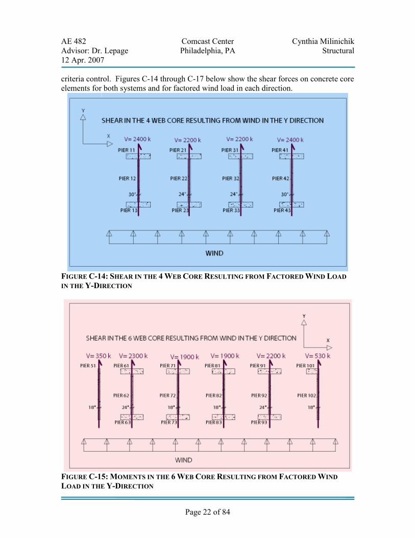
C.3.3.6 SHEAR STRESSES AND SHEAR REINFORCING
The shear stresses experienced by the concrete core due to wind loads are much smaller than the shear capacity of the webs. This characteristic indicates that serviceability
AE 482 Comcast Center Cynthia Milinichik Advisor: Dr. Lepage Philadelphia, PA Structural 12 Apr. 2007
Page 22 of 84
criteria control. Figures C-14 through C-17 below show the shear forces on concrete core elements for both systems and for factored wind load in each direction.
FIGURE C-14: SHEAR IN THE 4 WEB CORE RESULTING FROM FACTORED WIND LOAD
IN THE Y-DIRECTION
FIGURE C-15: MOMENTS IN THE 6 WEB CORE RESULTING FROM FACTORED WIND
LOAD IN THE Y-DIRECTION

AE 482 Comcast Center Cynthia Milinichik Advisor: Dr. Lepage Philadelphia, PA Structural 12 Apr. 2007
Page 23 of 84
FIGURE C-16: MOMENTS IN THE 4 WEB CORE RESULTING FROM FACTORED WIND
LOAD IN THE X-DIRECTION
FIGURE C-17: MOMENTS IN THE 6 WEB CORE RESULTING FROM FACTORED WIND
LOAD IN THE X-DIRECTION
C.3.3.7 EFFECTS ON CONSTRUCTION PROCESS
Reducing the size of the concrete core from a 6 web system to a 4 web system will affect several aspects of the construction process. Currently the concrete core construction is on a 3-day cycle in which the forms are placed, the rebar cages are installed and the concrete is poured and after a period of curing the forms are removed and jacked up. The process of jacking and resetting the forms and installing the rebar takes approximately two days. An entire day is needed to pump the concrete into the forms. The core originally started

AE 482 Comcast Center Cynthia Milinichik Advisor: Dr. Lepage Philadelphia, PA Structural 12 Apr. 2007
Page 24 of 84
out as a 4-day cycle and through experience and overtime the schedule achieved a 3-day cycle. The four web system would likely not be able to reduce the number of days the cycle is at but would reduce the amount of labor required by approximately one third since there are two less elements to form, set, and pour.
C.3.3.8 EFFECTS ON MECHANICAL SYSTEM
Eliminating the two concrete walls that encase the mechanical systems on either side of the building introduces freedoms for the Mechanical system. Currently the mechanical systems are tightly arranged in the concrete core. A rated partition can be used to achieve the required fire rating. A rated gypsum wall board partition could be easily adjusted for any changes in the mechanical system. For instance, if part of the mechanical system needed to be removed and replaced other pieces of equipment may need to be removed in order to do so. This could be very disruptive to the building functions. With a rated partition it may be simpler to remove a section of the wall and repair the wall. Figure C-18 illustrates the tightly arranged mechanical system in the concrete core.
FIGURE C-18: MECHANICAL SYSTEM
TIGHTLY ARRANGED IN CORE

AE 482 Comcast Center Cynthia Milinichik Advisor: Dr. Lepage Philadelphia, PA Structural 12 Apr. 2007
Page 25 of 84
C.3.3.9 SUMMARY AN D CONCLUSION
The existing concrete core of the Comcast Center is composed of I-sections with a total of 6 webs. Two of the web elements are 24 inches thick while the four remaining web elements are 18 inches thick. The proposed system consists of 4 web elements. The outer two webs are 30 inches thick while the inner two web elements are 24 inches. Both structures were modeled in Etabs to solve for the natural period of vibration. The natural period of vibration for the designed building was known however it would have been impractical to compare the 4 web system to this number due to differing design and modeling assumptions. Thus the 6 web system was modeled to try and simulate the designed structure to as close a degree as possible. The natural period of vibration of the proposed 4 web system in the critical mode 1 direction is only 3.5% greater than the modeled 6 web system. Reducing the core from 6 webs to 4 webs significantly softened the building in the mode 2 direction. Four coupling beams were eliminated along with the shear walls causing the period to increase by 16.7%. The Tuned Liquid Column Damper can be adjusted to accommodate these changes in the stiffness of the building to control deflections and accelerations. The flexural and shear reinforcing are required to meet minimal requirements indicating that stiffness controls over strength. The 4 web core is recommended over the 6 web core because of the additional freedoms achieved through it as well as the additional cost savings and increased net rentable area.
C.4 ALTERNATIVE #2: STEEL BRACED FRAME CORE
C.4.1 PROPOSED SOLUTION
The second alternative core system considered the substitution of a steel braced frame core in place of the concrete core. Figure C-20 indicates that the braced frames will be replacing the entire concrete core.

AE 482 Comcast Center Cynthia Milinichik Advisor: Dr. Lepage Philadelphia, PA Structural 12 Apr. 2007
Page 26 of 84
C.4.2 EXPECTED OUTCOME
C.4.2.1 EXPECTED ADVANTAGES
Using a braced steel frame in place of a concrete core will likely decrease construction time since the existing concrete system requires curing time.
C.4.2.2 EXPECTED DISADVANTAGES
Since the braced frame system is not as rigid as the existing concrete system the drift may be greater. The temporary cranes used to erect the existing system were easily braced by the existing concrete core. The steel framed core may not allow for such an easy connection.
C.4.3 RESULTS
A preliminary estimate was made in which it was determined that a steel braced core would not be economical over a concrete core. This decision was based on the consideration of project location, local materials, and opening sizes in the shear walls. These assumptions were later confirmed in a discussion with the Structural Engineer.
FIGURE C-20: STEEL BRACED FRAMES REPLACE THE EXISTING
CONCRETE CORE AS A SECOND ALTERNATIVE

AE 482 Comcast Center Cynthia Milinichik Advisor: Dr. Lepage Philadelphia, PA Structural 12 Apr. 2007
Page 27 of 84
The Structural Engineer indicated that a steel braced frame core was considered but abandoned early in the design process due to the extremely high steel tonnage required (Eisenreich). As a result, the steel braced frame alternative was disregarded and resources were allocated to other areas of this thesis.
C.5 ALTERNATIVE #3: REDUCING THICKNESS OF WEB ELEMENTS AND FLANGE ELEMENTS
C.5.1 PROPOSED SOLUTION
A significant amount of weight can be removed from the concrete core by reducing the thickness of the web and flange elements. This theory will be applied to a 6 web concrete core system.
C.5.2 EXPECTED OUTCOME
C.5.2.1 EXPECTED ADVANTAGES
Reducing the thickness of the flange and web elements of the concrete core will decrease the weight of the structure. Less material will be used which will decrease the cost of the structure. Net rentable space will be gained increasing the Owner’s revenue.
C.5.2.2 EXPECTED DISADVANTAGES
Decreasing the thickness of the concrete core elements may eliminate some of the redundancy built into the structure to avoid progressive collapse.
C.5.3 RESULTS
The reduced 6 web system has 6 web elements all measuring 18 inches in thickness. Both flanges in the reduced 6 web system are decreased by 12 inches. The natural period of vibration was calculated using an Etabs model which was compared to the 6 web model of the existing concrete core. Figure C-21 below summarizes the periods of the two systems. The reduced 6 web system has a Mode 1 period of 9.20s which is 8.5% greater than the period calculated for the 6 web Etabs model of the existing core. The period is within 10% which suggests that this reduced configuration will work for this building. The additional damping required by the system to meet serviceability criteria could be met by adjusting the tuned liquid column damper or increasing the strength of the concrete. Since the benefits of this reduced 6 web system are rather limited as compared to the freedoms of the 4 web system no further criteria were checked for this system. However, keeping a 6 web system would allow for all building life systems to be incased in the concrete core.

AE 482 Comcast Center Cynthia Milinichik Advisor: Dr. Lepage Philadelphia, PA Structural 12 Apr. 2007
Page 28 of 84
A net area of 305 SF will result from the reductions made to the concrete core. This will increase the profits by $8.3M per year. The core will require 12,800 less cubic yards of concrete which will result in significant savings.
C.6 STRUCTURAL DEPTH SUMMARY
Of the three systems assessed in the structural depth; the four web core, steel braced frame core, and the reduced 6 web core, the most economical system is the 4 web core. The steel braced frame system was eliminated in the early design stages because of the extremely large tonnage and cost effective alternative of concrete. The large openings in the core would have created difficulties for the braced frame system. The third alternative investigated the possibilities of making the web and flange elements thinner. Reducing the thickness of these elements resulted in a 7.23% greater period in the mode 1 direction. Since the period increased by less than 10% the reduced 6 web system is still a practical alternative, however further investigation would be required to verify this. The reduced 6 web system would allow for all life systems to be incased in the concrete core. The 4 web system allow for more flexibility in the floor plan. Additional space for parking in the three levels of below grade parking resulted from removing two webs. The mechanical rooms benefit from more flexibility in layout and access when a rated partition is used in place of an 8 inch thick concrete wall. Approximately $950,000 is saved on materials which is enough to purchase the Tuned Liquid Column Damper at the top of the tower. In conclusion, the 4 web system is recommended.
D. BREADTH TOPICS
D.1 SUSTAINABILITY & LEED RATING BREADTH: ENERGY COLLECTION SYSTEMS
D.1.1 PROBLEM BACKGROUND
The Comcast Center has a very large surface which is exposed to a tremendous amount of energy from the sun. Low-E tinted glass makes up the entire façade. The Comcast Center will be just one of the many LEED Rated buildings developed by Liberty Property Trust. The Comcast Center is 1001.5 feet tall and is subject to high wind speeds at the top of the structure.
FIGURE C-21: COMPARISON OF THE NATURAL PERIOD OF
VIBRATION FOR THE MODELED 6 WEB SYSTEM AND THE REDUCED
6 WEB SYSTEM

AE 482 Comcast Center Cynthia Milinichik Advisor: Dr. Lepage Philadelphia, PA Structural 12 Apr. 2007
Page 29 of 84
As conventional energy sources continue on their path to depletion wind energy sources are gaining popularity. Wind, defined as air in motion, carries kinetic energy which can be converted into mechanical or electrical energy. Having little to no impact on the environment, wind energy is considered a green power technology. Unlike certain conventional energy sources, wind power does not pollute the air or produce green house gasses. Wind energy is both renewable and reliable (Tiwari 338).
D.1.2 PROBLEM STATEMENT
A tremendous amount of energy from the sun and the wind reaches the façade of the Comcast Center. If this energy can be collected and stored in an economical way, the Comcast Center could benefit from these green energy technologies.
D.1.3 PROPOSED SOLUTION
The feasibility of adding an energy collecting system to the Comcast Center was assessed. The first system involves placing small wind turbines at the parapet. The small turbines are not visible and generate a large amount of energy. The second system would collect the energy from the façade by using glazing that has photovoltaic (PV) patches between the two panes of glass. The patches can vary in size and would be hardly visible.
D.1.5 EXPECTED OUTCOME
The miniature wind turbines may prove more effective since they do not impact the architecture of the building. Both systems might be necessary to collect enough energy to run the entire building. Using both systems may prove to be more effective in that on a clear sunny day there is no wind but on a cloudy day there is likely much more wind.
D.1.5.1 EXPECTED ADVANTAGE
The energy collected could be used to power the electrical elements of the Comcast Center or supplied to Philadelphia’s electrical grid.
D.1.5.2 EXPECTED DISADVANTAGE
A likely disadvantage of the energy collecting system is the high upfront cost of the system. Since these systems are relatively new, maintenance and repairs on them may cost a significant amount more than a traditional system.

AE 482 Comcast Center Cynthia Milinichik Advisor: Dr. Lepage Philadelphia, PA Structural 12 Apr. 2007
Page 30 of 84
D.1.6 RESULTS
D.1.6.1 WIND TURBINE RESULTS
Various parameters determine whether or not a wind turbine is practical in a certain location. Such parameters include mean wind speed and directional data, variations about the mean in the short span, and daily, seasonal and annual variations. Figure D-1 below lists the average wind speeds in mph experienced in Philadelphia over 61 years. The average wind speeds over the course of a year range from 8.0 mph to 11.3 mph. The average annual wind speed is 9.5 mph.
Figure D-2 below defines the components of horizontal and vertical axis turbines. Some of the common components include a rotor blade, gearbox, generator, and rotor blade. A diagram of the energy extracting stream-tube of a wind turbine is given below in Figure D-3. Figure D-4 depicts principles of aerodynamics and how they relate to a wind turbine.
FIGURE D-2: CONFIGURATIONS OF HORIZONTAL AXIS AND
VERTICAL AXIS WIND TURBINES
FIGURE D-1: NOAA RECORDED MEAN WIND SPEED FOR CITIES IN PENNSYLVANIA

AE 482 Comcast Center Cynthia Milinichik Advisor: Dr. Lepage Philadelphia, PA Structural 12 Apr. 2007
Page 31 of 84
FIGURE D-3: THE ENERGY EXTRACTING STREAM-TUBE OF A WIND TURBINE
FIGURE D-4: PRINCIPLES OF WIND TURBINE AERODYNAMICS LIFT.

AE 482 Comcast Center Cynthia Milinichik Advisor: Dr. Lepage Philadelphia, PA Structural 12 Apr. 2007
Page 32 of 84
D.1.6.1.1 WIND TURBINE BUILDING APPLICATIONS AND EXAMPLES
Several buildings around the world have wind turbines to take advantage of the natural renewable energy of the wind. Bahrain World Trade Center has three wind turbines integrated into the architectural aesthetic. The turbine blades measure 95 feet in diameter. Approximately 11-15% of the building total energy, 1300 MegaWatt hours per year, will be generated by wind energy (Digital Journal). The Bahrain World Trade Center, pictured below in Figure D-5, serves as an example for how much energy can be expected from the current technology. It is not recommended that the Comcast Center incorporate a wind turbine into its architecture, instead the wind turbines proposed for the Comcast Center would not be visible. In Chicago, Mayor Daley announced the installment of wind turbines on top of the Richard J. Daley Center. The Daley Center is 680 feet tall; note that this is two thirds the height of the Comcast Center. The energy generated by the turbines will not go directly into the building system but instead into the city’s power grid. Information regarding the
FIGURE D-5: BAHRAIN WORLD TRADE CENTER

AE 482 Comcast Center Cynthia Milinichik Advisor: Dr. Lepage Philadelphia, PA Structural 12 Apr. 2007
Page 33 of 84
amount of energy that the wind turbines will produce is not available; however it is known that these turbines contribute to Chicago’s goal of having 20% of the city’s energy supplied by renewable sources (PBC Chicago). By incorporating wind turbines into the Comcast Center, Philadelphia could follow in Chicago’s example to aid the advancement of wind energy technology.
D.1.6.1.2 ROOF TOP WIND TURBINE MANUFACTURERS AND PRODUCTS
A Finnish wind turbine manufacturer known as Windside has a unique noiseless wind turbine featured in Figure D-6 below. Unlike other wind turbine configurations, the Windside Turbine spins in even light breezes. Windside manufactures turbines for normal to extremely cold and icy weather conditions. Most turbine manufacturers in the U.S. do not offer turbines that can be placed on rooftops. Windside specifies a line of turbines that can be used for rooftops.
Bill Becker, Professor of Industrial Design at the University of Illinois, designed a wind turbine for urban settings called Aeroturbines. The turbines have been installed on several buildings including the Daley Center in Chicago (PBC Chicago). Aeroturbines have been rated to produce 1-1.8kW in 30 mph winds. The turbines are noise free, safe for birds and low maintenance. The self regulating turbines are able to utilize milti-directional and gusting winds. The approximate cost ranges from $15,000 to $21,000 and are projected to decrease significantly with mass production. Using the Building Area Method defined in the National Electric Code 2005 the Comcast Center uses approximately 11,700 KVA. The building area assumed was 1.2M SF. For estimating purposes 1 KVA was approximated to be 1kW. Philadelphia experiences a
Photograph Courtesy of Windside
FIGURE D-6: WINDSIDE WIND TURBINES

AE 482 Comcast Center Cynthia Milinichik Advisor: Dr. Lepage Philadelphia, PA Structural 12 Apr. 2007
Page 34 of 84
mean wind speed of 9.5mph at a height of 30’ throughout the year. The turbines at the roof level will experience much greater wind speeds. A wind gradient formula was used to determine that the wind speed at 1000’ in Philadelphia is 83 mph. Assuming a linear relationship between the wind speed and the output of the wind turbine yields 2.8 kW per turbine. The size of the turbine and the available area on the roof play a role in the number of practical turbines. Four large cooling towers are situated on the roof. Each turbine is in a cage measuring 5 feet by 5 feet by 10 feet tall. Various layouts were considered to compare the cost and benefit of a certain number of turbines. The summary featured below in Figure D-7 indicated that 38 turbines would produce 106.4kW which is less than 1% of the building’s total estimated energy. Spacing the turbines at every 10 feet on center along the perimeter is a practical upper limit. Half a million dollars would result in 106.4 kW in savings. Compared to the three 95 foot diameter turbines on the Bahrain World Trade Center, these turbines have a very low efficiency. A more accurate calculation could yield a greater percentage of total building energy.
Despite the limited economic gain it is still recommended that the Comcast Center utilize natural renewable wind energy. Through mass production the price of the turbines will decrease significantly. As the new tallest skyscraper in Philadelphia the Comcast Center is a very high profile building. The city had requested that the Construction Manager hirer local contractors to encourage the sense of pride in the city. Investing resources into new technology to benefit the future of renewable energy resources would be in keeping with this concept.
D.1.6.1.3 CURRENTLY RESEARCHED SYSTEMS
Researchers at the University Hong Kong are currently studying a new system of wind turbines that promises to be more cost effective than traditional wind turbines. These mini turbines are made of plastic and are approximately one foot in diameter. The secret to the cost efficiency of this system is mass production and material type to lower the upfront cost of the system. The mini turbines can be linked together in arrays to meet the
FIGURE D-7: SUMMARY OF TURBINE SYSTEM

AE 482 Comcast Center Cynthia Milinichik Advisor: Dr. Lepage Philadelphia, PA Structural 12 Apr. 2007
Page 35 of 84
energy and space requirements of each application (Green). Figure D-8 shows how the mini turbines can be arranged. Since the system is still being studied, and therefore was not available at the time of the design of the Comcast Center, it is not practical to consider this as a solution.
D.1.6.1.4 WIND TURBINE CONCLUSIONS
At 1001 feet the Comcast Center has a unique advantage over other structures in the city. The tower has unlimited access to a natural renewable source of energy. Although wind energy is an old technology, its applications to buildings are still being refined. Over time as wind technology gains popularity it will become much more cost effective. It is recommended that the Comcast Center, as a symbol of Philadelphia, utilize its convenient access to wind energy. Since at the time of construction the technology is not cost effective and the electrical system is already completed, wind turbines could be installed at a later date to supply energy to the city’s grid.
D.1.6.2 PHOTOVOLTAIC CELLS RESULTS AND CONCLUSIONS
To reduce the amount of energy consumed through the transportation process it can be beneficial to use materials from local manufacturers. Furthermore, local manufacturers tend to be aware of the environmental conditions for the area and therefore can produce a better product and provide advice for commonly encounter problems. There are several photovoltaic cell manufacturers near Philadelphia. The closest manufacturer is Advanced Systems Manufacturing, Inc. in Princeton, New Jersey which is only an hour away from Philadelphia. In Pennsylvania, the closest photovoltaic cell manufacturer is 5 hours away in Belle Solar Power Industries, Inc (Source). After closer consideration of the photovoltaic patch system it was determined that there are only a few areas where the photovoltaic cells could be located. The majority of the glass cladding has a reflective quality. Figure D-9 displays the reflective and transparent
FIGURE D-8: PLASTIC MINI WIND
TURBINES CURRENTLY BEING STUDIED

AE 482 Comcast Center Cynthia Milinichik Advisor: Dr. Lepage Philadelphia, PA Structural 12 Apr. 2007
Page 36 of 84
glass types of the façade. If a photovoltaic (PV) patch were to be sandwiched between panes of glass behind the reflective coating the amount of energy that reaches the PV cell would be limited. This would be an inefficient and possibly ineffective system. Situating the PV patch before the reflective coating would significantly affect the architecture. Unless the Architect chose to incorporate this look into the façade of the building the PV patches are not a viable solution. The atrium and main entrance of the Comcast Center along JFK Blvd. is enclosed with transparent glass cladding. The PV patches could be incorporated into this glass façade however there are several reasons this may not work architecturally and functionally. The three level atrium will feature a winter garden full of trees and plants, the PV system would compete for sunlight with this system. To collect a high enough percentage of electricity through the PV patches a certain ratio of the glass façade would be dedicated to this system. Also in the atrium sculptures of people walking will be featured as part of a Philadelphia requirement that 1% of a building cost be dedicated to artwork to benefit the local artists’ community (Maule). The PV patch system could compromise the visibility of the famous artwork. As a result it is not recommended that a PV system be incorporated into the façade without close correspondence with the Architect.
PHOTOGRAPH COURTESY R. BRADLEY MAULE
FIGURE D-9: TRANSPARENT GLASS
ATRIUM VS. REFLECTIVE GLASS TOWER

AE 482 Comcast Center Cynthia Milinichik Advisor: Dr. Lepage Philadelphia, PA Structural 12 Apr. 2007
Page 37 of 84
D.2 CONSTRUCTION MANAGEMENT BREADTH
D.2.1 PROBLEM BACKGROUND
The Comcast Center is located in downtown Philadelphia. The lot is defined by John F. Kennedy Boulevard, Arch Street and 17th Street. The Comcast Center will be the new tallest building between New York and Chicago.
D.2.2 PROBLEM STATEMENT
This urban location limits the space available for the site layout and causes site scheduling to become very critical. The site layout out is also restricted by the limited space. Figures D-10 and D-11 below show an aerial view of the construction site. With the goal of obtaining a LEED Rating, the upfront costs will likely be rather high.
PHOTOGRAPH COURTESY OF GOOGLE MAPS
FIGURE D-10: COMCAST SITE PRIOR TO ANY CONSTRUCTION

AE 482 Comcast Center Cynthia Milinichik Advisor: Dr. Lepage Philadelphia, PA Structural 12 Apr. 2007
Page 38 of 84
D.2.3 PROPOSED SOLUTION
Construction issues will be discussed and assessed in order to get a better understanding of how to make design decisions that facilitate the construction process.
D.2.4 EXPECTED OUTCOME
D.2.4.1 EXPECTED ADVANTAGES
Considering the application of the design is a good practice to adopt which can prevent issues and save money.
D.2.4.2 EXPECTED DISADVANTAGES
Although similar situations may occur on different projects, each project has its own set of conditions which may cause one solution to work in a given situation over another.
D.2.5 RESULTS
D.2.5.1 SCHEDULE INFORMATION
Primavera was used by the Construction Manager to create the schedule. The schedule for the Comcast Center began on January 19th 2004 with Construction Drawing Set and is planned to end February 11th 2008. Work on the foundation began January 18th and the concrete core on October 4, 2005. The structural steel erection started on December 27, 2005.
PHOTOGRAPH COURTESY OF R. BRADLEY MAULE
FIGURE D-11: THE TRAILER PORTION OF THE
CONSTRUCTION SITE AS SEEN FROM STANDING IN THE
TOWER

AE 482 Comcast Center Cynthia Milinichik Advisor: Dr. Lepage Philadelphia, PA Structural 12 Apr. 2007
Page 39 of 84
Critical path items are identified on the schedule by the color red. The concrete core is a part of the critical path for levels B2 through 6. A portion of the schedule is featured below in Figure D-12.
D.2.5.2 COST INFORMATION Due to the massive amount of concrete used to create the concrete core the cost of the concrete for the entire project was close to the cost of the steel. The cost for 12,500 tons of steel was approximately $38,250,000 whereas the cost of the concrete was $26,703,000 for 37,000 yards.
D 2.6 CONSTRUCTION ISSUES
Even the most detailed and well thought out design documents can be subject to revision during the construction process due to tolerance, schedule, and constructability issues. Some of the construction issues L.F. Driscoll encountered while working on the Comcast Center are described below.
FIGURE D-12: PORTION OF CONSTRUCTION SCHEDULE

AE 482 Comcast Center Cynthia Milinichik Advisor: Dr. Lepage Philadelphia, PA Structural 12 Apr. 2007
Page 40 of 84
D.2.6.1 CREEP EFFECTS IN THE CONCRETE CORE
The differing material properties of concrete and steel pose a complicated problem for designers and contractors. Over time concrete experiences a phenomenon known as creep. Creep can be defined as the time-dependant strain occurring under stress. The large gravity forces applied to the concrete core will over time cause the core to shrink at a different rate than the perimeter steel columns. The floor plates are supported by the steel members that connect to columns at the perimeter of the building and frame into the core at the center. As the concrete core shrinks vertically the floor plate will begin to rotate in toward the center possibly causing problems for interior finishes. This phenomenon does not pose any structural threats as it is a very small movement and occurs over a long period of time. A floor plate is graded by two sets of criteria; floor levelness (FL) and floor flatness (FF). Floor levelness is the degree to which a floor is level whereas floor flatness is a measure of how flat the floor is. A floor may be completely flat but not level. This is an important distinction for construction managers and contractors that can greatly impact finishes (Klodarska). To counter the effects of creep on the floor levelness the Structural Engineers calculated an adjustment that would move each floor plate connection up 1/16th inch higher on the concrete core than its connection to the steel perimeter columns. After meeting with L.F. Driscoll onsite, I was informed that the concrete core has already experienced a creep greater than 1/16th inch and the floors are slightly rotated inward. This rotation could affect pre-manufactured finishes such as the movable glass partition walls being installed in the Comcast office spaces since it may be difficult to adjust them
D.2.6.2 TUNED LIQUID COLUMN DAMPER
Constructability is an important factor in a project of this scale. The tuned liquid column damper (TLCD), originally designed as cast-in-place, was re-designed during the construction phase to accommodate the steel erection schedule. The original cast-in-place system would require formwork which would delay the erection of the remaining steel for the crown. The pre-cast system will cut construction time from 4-5 months to 4-5 weeks. The original cast-in-place system would be exposed to high winds and possible extreme temperatures and weather at the top of the 1000 foot tower during the concrete curing process. These conditions can compromise the integrity of the TLCD system. Pre-cast elements are manufactured in a controlled environment granting a greater degree of quality control. A disadvantage of the pre-cast system is the inability to make adjustments for tolerances in construction. The formwork of the original cast-in-place system could be easily adjusted to accommodate tolerances.

AE 482 Comcast Center Cynthia Milinichik Advisor: Dr. Lepage Philadelphia, PA Structural 12 Apr. 2007
Page 41 of 84
Concrete would have been pumped from the base of the tower for the original pre-cast system only requiring the crane for the form work. The pre-cast system will require the use of the crane to lift the pre-cast elements into place. This could affect the steel erection schedule, however the time savings for the pre-cast system is already much greater than the original cast-in-place system. In order to integrate the pre-cast system into the existing cast-in-place concrete core the top of the concrete core was formed with 36 inch deep notches to accommodate the 36 inch deep beams. The notches are illustrated below in Figure D-13.
Typically a pre-cast system would cost significantly less than a cast-in-place system. Some factors that allow for pre-cast systems to offer a more competitive price result from less expensive labor costs, greater quality control through controlled conditions, and greater volume output. However since the design occurred during the construction phase other systems were already designed around the damper creating a lot of restraints for the pre-cast system. As a result the redesigned tuned liquid column damper will cost significantly more than the original however this system reduces the schedule by such a great degree that the extra damper cost does not reflect in the over cost of the building. The cost of the original cast-in-place damper would have been $905,000. The cost of the new system was not known at the time of this report.
PHOTOGRAPH COURTESY R. BRADLEY MAULE
FIGURE D-13: THE 36 INCH NOTCHES AT THE TOP
OF THE CONCRETE CORE ALLOW FOR THE TUNED
LIQUID COLUMN DAMPER TO BE INTEGRATED INTO
THE CONCRETE CORE.

AE 482 Comcast Center Cynthia Milinichik Advisor: Dr. Lepage Philadelphia, PA Structural 12 Apr. 2007
Page 42 of 84
D.2.6.3 CRANE LOCATIONS
The construction of the Comcast Center superstructure began with two cranes, one on Arch Street and one on JFK Blvd. In Figure D-14 below the crane operator is accessing the crane. As the core is topped off and the steel framed floor plate decreases in area the cranes will be taken down and a new crane will be placed in a more advantageous location.
Figure D-15 below is a layout of the existing and future crane locations. The circles illustrate the amount of load that can be handled at a given radius. Once the centrally located crane and derrick are installed the derrick crane will be used to disassemble the two exterior cranes. The crane will be used to erect the pre-cast pieces of the tuned liquid column damper and the steel framing of the crown. The centrally located crane is fastened to the foundation and runs through the concrete core. Removing the two exterior cranes allows for the glass cladding to be installed. Finishes and elevators for the core area in which the central crane is located will have to be postponed until the crane can be removed. This can affect cost and the timing of trades.
PHOTOGRAPH COURTESY R. BRADLEY MAULE
FIGURE D-14: CRANE OPERATOR ACCESSING CRANE

AE 482 Comcast Center Cynthia Milinichik Advisor: Dr. Lepage Philadelphia, PA Structural 12 Apr. 2007
Page 43 of 84
D.2.7 SUMMARY AND CONCLUSIONS
Despite harsh weather conditions such as high winds, freezing temperatures and snow the Construction Manager has been able to maintain the schedule. The Comcast Center is currently at a transition phase between crane locations. The two exterior tower cranes will be replaced by a centrally located crane and a derrick. As a result of the thick flange and web elements of the concrete core the cost of the concrete approaches the cost of the steel. Reducing the size of the concrete core as recommended earlier in this report would reduce cost of the project significantly. Many issues arise during the construction phase regarding application, constructability, tolerances and schedule. The tuned liquid column damper was redesigned in pre-cast to facilitate the steel erection schedule of the crown resulting in significant time and money savings. Studying these issues will result in better design decisions to facilitate the construction process.
FIGURE D-15: EXISTING AND FUTURE CRANE LOCATIONS

AE 482 Comcast Center Cynthia Milinichik Advisor: Dr. Lepage Philadelphia, PA Structural 12 Apr. 2007
Page 44 of 84
D.3 ARCHITECTURE BREADTH
D.3.1 PROBLEM BACKGROUND
The reduction of the concrete core from 6 web elements to 4 web elements suggests changes to the layout of the vertical transportation system. The current design of the elevators consists of 35 elevators. Four elevator banks service different levels of the tower; a high rise bank, a high mid-rise bank, a low mid-rise bank and a low rise bank. Each bank consists of 4 elevators. A system called Destination Dispatch is used to facilitate the flow of vertical traffic at the peak times of the day. Occupants that enter the elevator bank swipe a card with their floor information on it. A software program organizes the data to plan the most efficient trips and directs the occupant to the designated elevator.
D.3.2 PROPOSED SOLUTION
Many factors play a role in the design of the elevator system. Such factors include elevator capacity, elevator dimensions and size, the number of stop, distance traveled, speed of system, and wait time. The large number of factors suggests that there is flexibility in the design. Adjusting these factors could reduce the number of elevators needed.
D.3.3 EXPECTED OUTCOME
D.3.3.1 EXPECTED ADVANTAGES
If one or two elevators can be eliminated than it may be possible to rearrange the stairwell to increase net rentable space. Reducing the number of elevators can significantly impact the cost of the elevator system.
D.3.3.2 EXPECTED DISADVANTAGES
Reducing the number of elevators can eliminate the possibility of redundancy. If an elevator were to be shut down for a period of time for maintenance or a problem the wait time could significantly increase.
D.3.4 ELEVATOR DESIGN RESULTS
According to George Starkosch’s Vertical Transportation Handbook, there are certain limits to the variables of an elevator system. For example, the dimensions of the cab may be adjusted but it is important to keep a wide and shallow cab shape to minimize losses. In an elevator setting it can be assumed that most people will be comfortable with a 3 foot diameter of space around them. During busy conditions people will tend to stand with a 2 foot diameter of space around them. To determine appropriate dimensions of

AE 482 Comcast Center Cynthia Milinichik Advisor: Dr. Lepage Philadelphia, PA Structural 12 Apr. 2007
Page 45 of 84
and elevator cab it can help to use a diagram similar to the one featured below in Figure D-16.
Over the course of history new elevator technologies were discovered. Such systems include the steam-driven hoist, the electric-driven hoist, hydraulic, traction, geared and gearless. The most economical elevator for a given building depends on its occupancy loads, time requirements, size requirements and overall height of the building. Figure D-17 below illustrates the components of a hydraulic elevator.
FIGURE D-16: DIAGRAM OF ELEVATOR OCCUPANT SPACING

AE 482 Comcast Center Cynthia Milinichik Advisor: Dr. Lepage Philadelphia, PA Structural 12 Apr. 2007
Page 46 of 84
According to Ray Hahn of Persohn/Hahn Associates, the Comcast Center experiences its peak time in the morning. The longest interval of time an individual can expect to wait for and elevator is 30 seconds. The average wait that an occupant would experience is approximated by 70% of the interval, yielding 26 seconds for the Comcast Center. The typical capacity of an office building elevator is 3500 lbs. For a larger floor plate they could considered a 4000 lbs elevator capacity. Although using double-deck elevators can save time and increase efficiency, these elevators have large upfront cost which is why the owner rejected that option (Hahn). Approximately 50 studies were performed on the Comcast Center to determine the number of sufficient elevators. This is an unusually large number of studies (Hahn). The results of one study are given below in Figure D-18. These results are not necessarily reflective of the current design.
FIGURE D-17: HYDRAULIC ELEVATOR

AE 482 Comcast Center Cynthia Milinichik Advisor: Dr. Lepage Philadelphia, PA Structural 12 Apr. 2007
Page 47 of 84
D.3.5 SUMMARY AND CONCLUSIONS FOR ELEVATOR SYSTEM
Given the current elevator technology the vertical transportation system of the Comcast Center cannot be decreased at this time. With advancements in elevator technology this goal will be achievable. It would not make sense to adjust the existing elevator system when technology advances; therefore it is recommended to keep the existing design.
E. SUMMARY & CONCLUSIONS Based on the information gather and the results of the analyses the Comcast Center could benefit from a few recommendations. It is to be expected that one design change will impact other areas of the building, which is why each alternative was carefully assessed to determine its effects on the whole building. Increasing the width of each web element by 6 inches and removing the two outer web elements will allow for greater freedoms in the floor plan. The mechanical systems currently tightly arranged in the core will have
STUDY RESULTS
Low Rise Low Mid Rise
No. of Elevators Four (4) No. of Elevators Eight (8)
Floors Served 1, 3 to 12 Floors Served 1,12**,13 to 27
Capacity 3500 lbs. Capacity 4000 lbs.
Speed 700 fpm Speed 800 fpm
Interval 29.6 sec. Interval 22.7 sec.
Handling Capacity 12.2% Handling Capacity 12.6%
Population 1077 Population 1626
Population/Floor (avg) 108 Population/Floor (avg) 108
** 12 is a limited transfer floor in low mid rise bank.
High Mid Rise High Rise
No. of Elevators Eight (8) No. of Elevators Seven (7) *
Floors Served 1, 27** 28 to 43
Floors Served 1, 43**, 44 to 56
Capacity 4000 lbs. Capacity 4000 lbs.
Speed 1200 fpm Speed 1200 fpm
Interval 26.9 sec. Interval 29.4 sec.
Handling Capacity 12.3% Handling Capacity 12.4%
Population 1729 Population 1287
Population/Floor (avg) 108 Population/Floor (avg) 99
FIGURE D-18: ELEVATOR STUDY RESULTS

AE 482 Comcast Center Cynthia Milinichik Advisor: Dr. Lepage Philadelphia, PA Structural 12 Apr. 2007
Page 48 of 84
greater flexibilities. For example a door can be installed in a location that best fits the mechanical layout for maintenance or repair work. With a concrete wall the means of access to the equipment are limited. Eliminating two web elements also introduces freedoms into the below grade parking levels. Additional parking spaces can be incorporated into the garage space. Reducing the concrete to 4 webs increases the net rentable area by 45 SF per floor. The 4 web system analyzed offers greater benefits over the reduced 6 web system. If the owner prefers to have all life systems enclosed in the concrete core than the reduced 6 web system would be a suitable alternative. The steel braced frame alternative was eliminated early in the design phase. In conclusion the most economical lateral system is the 4 web system. As the tallest building in Philadelphia, the Comcast Center has unlimited access to a renewable energy source, wind. It is recommended that small wind turbines be installed on the roof to generate electricity. Wind energy technology as it pertains to buildings is still in its developmental stages, as a result there are rather high initial costs. Through mass production the costs can be decreased. It is recommended that Philadelphia follow Chicago’s example and install wind turbines on the rooftop of the Comcast Center to encourage the advancement of renewable wind energy. During the construction process a design may need to be adjusted to accommodate issues of constructability, tolerances, schedule and local materials and labor. The tuned liquid column damper, which provides supplemental damping, was originally designed as a cast-in-place system. The logistics of the steel framing suggested that a pre-cast system be utilized. The pre-cast system will save a significant amount of time over the cast-in-place system. The concrete mix supplied for the concrete core had a greater cement ratio than specified to account for the chemical changes due to pumping. The resulting concrete core is significantly stiffer than the designed core. The Tuned Liquid Column Damper will need to be tuned to meet the needs of the building. Steel framed buildings with concrete cores are subject to a unique axial shortening issue. As the concrete core is subject to greater and greater stresses over time it experience creep. As a result the concrete core shortens at a different rate than the steel columns. Although measurements can be calculated the actual behavior of the structure is affected by many factors. As a result these issues need to be addressed during the construction phase. It is recommended that these types of issues be studied so that better decisions can be made during the design process to facilitate the construction process. The vertical transportation system of the Comcast Center is comprised of 35 elevators. The amount of elevators required to meet the building vertical transportation needs strongly influences the size of the concrete core. Reducing the amount of elevators required will facilitate the reduction of the concrete core to a 4 web system. The designed elevator system will involve card access turnstiles that direct an individual to a certain elevator. The elevator banks are designed to only service certain levels of the building to further expedite transportation. Advancements in elevator technology can be utilized to reduce the size and quantity of the elevators required.

AE 482 Comcast Center Cynthia Milinichik Advisor: Dr. Lepage Philadelphia, PA Structural 12 Apr. 2007
Page 49 of 84
F. ACKNOWLEDGEMENTS I’d like to sincerely thank everyone that helped me with my Senior Thesis Project. Without their assistance I wouldn’t have been able to learn as much as I did. With the Comcast Center under construction this was an especially busy time for the project team. I greatly appreciate the efforts of the project team to answer my question during this extremely busy time. I also received a great deal of assistance from the AE Faculty during my year long study. From questions about software programs to overall thesis perspective and everything in between, the AE faculty was more than willing to offer their time. I would also like to thank my family who supported me during my entire education here at Penn State. A special thank you goes to my sister, April, who rearranged her schedule to venture into the city and tour the Comcast Center with me. The following is a list of individuals I’d like to thank: Project Team: Jim Verzella, Vice President, L. F. Driscoll Joe Klodarska, Project Manager, L. F. Driscoll Stephan Eisenreich, Project Engineer, Thornton Tomasetti Ray Hahn, CEO, Persohn/Hahn Associates Faculty: Dr. Andres Lepage, Advisor, AE Faculty Professor M. Kevin Parfitt, AE Faculty Professor Robert Holland, AE Faculty Dr. David Riley, AE Faculty AE Department Faculty and Staff Photographer/Historian R. Bradley Maule, Phillyskyline

AE 482 Comcast Center Cynthia Milinichik Advisor: Dr. Lepage Philadelphia, PA Structural 12 Apr. 2007
Page 50 of 84
G. REFERENCES Aerotecture International, Inc. “Aeroturbines.” 2007. 12 Apr. 2007.
<http://www.aerotecture.com/index.html>
Baker, William et all. “Trump International Hotel and Tower.” Concrete International. July 2006: 28-32.
Eisenreich, Stephan, Project Engineer, Thornton Tomasetti. Telephone Interview. 1 Feb. 2007. Digital Journal. “World’s First Building-Integrated Wind Turbine.” 26 Mar. 2007.
11 Apr. 2007. < http://www.digitaljournal.com/article/149643/World_s_First _Building_Integrated_Wind_Turbines>
Green Options. “Sustainable Revolutions: New, Small Wind Turbines Make Big
Impact.” Green Options LLC. 20 Mar. 2007. 8 Apr. 2007. <http://www.green options.com/blog/2007/03/20/sustainable_revolutions_new_small_wind_turbines _make_big_impact>
Hahn, Ray, Chief Executive Officer, Persohn/Hahn Associates. Telephone Interview. 27 Feb. 2007.
Klodarska, Joseph A., Project Manager, L. F. Driscoll Co. Personal Interview.
13 Mar. 2007
Kostelni, Natalie. “Tallest Building on Track.” Philadelphia Business Journal. 23 Mar. 2007. 26 Mar. 2007. <http://philadelphia.bizjournals.com/philadelphia/
stories/2007/03/26/story1.html?b=1174881600^1435926> Maule, R. Bradley. Personal Interview. 13 Mar. 2007 Motioneering. “Our Portfolio.” 1 Apr. 2007.
<http://www.motioneering.ca/Public/Buildings.aspx>

AE 482 Comcast Center Cynthia Milinichik Advisor: Dr. Lepage Philadelphia, PA Structural 12 Apr. 2007
Page 51 of 84
Peri. “Skyscrapers: Comcast Center, Philadelphia, Pennsylvania.” Feb 2003. 3 Apr. 2007. <http://www.peri.de/ww/en/pub/projects.cfm/fuseaction/show reference/reference_ID/1018>
Philly Skyline. “Comcast Center under Construction.” 12 Apr. 2007.
<http://www.phillyskyline.com/bldgs/comcast/i2.htm> Public Building Commission of Chicago. “Mayor Daley Announces 2006 Environmental
Action Agenda.” 19 Apr. 2006. 31 Dec. 2006. <http://pbcchicago.com/subhtml/press/pr_wind_turbines.asp
Simiu, Emil and Robert H Scanlan. Wind Effects on Structures. 2nd ed.
New York: Wiley, 1986 Source for Renewable Energy, The. Momentum Technologies LLC. 2006. 8 Apr. 2007.
<http://energy.sourceguides.com/businesses/byGeo/US/byP/solar/pvC/byB/mfg/b yS/byS.shtml>
Strakosch, George R. Vertical Transportation Handbook. 3rd ed. New York:
Wiley, 1998. Tiwari, G. N., and M. K. Ghosal. Renewable Energy Resources: Basic Principles and
Applications. Harrow, U.K. Alpha Science International Ltd., 2005.
Verzella, James E., Vice President, L. F. Driscoll Co. Personal Interview. 13 Mar. 2007