07 + 4wd gm 1500 5” kit
TRANSCRIPT
Thank you for choosing Rough Country for your suspension needs. We appreciate your business!!
Rough Country recommends a certified technician install this system. In addition to these instructions, professional knowl-edge of disassemble/reassembly procedures as well as post installation checks must be known. Attempts to install this sys-tem without this knowledge and expertise may jeopardize the integrity and/or operating safety of the vehicle.
Please read instructions before beginning installation. Check the kit hardware. Be sure you have all needed parts and know where they go.
PRODUCT USE INFORMATION
As a general rule, the taller a vehicle is, the easier it will roll. Seat belts and shoulder harnesses should be worn at all times. Avoid situations where a side rollover may occur.
Generally, braking performance and capability are decreased when larger/heavier tires and wheels are used. Take this into consideration while driving. Do not add, alter, or fabricate any factory or after-market parts to increase vehicle height over the intended height of the Rough Country product purchased. Mixing component brands is not recommended.
Rough Country makes no claims regarding lifting devices and excludes any and all implied claims. We will not be responsi-ble for any product that is altered. We will be happy to answer any questions concerning the design, function, and correct use of our products.
This kit will not fit vehicles equipped with electric steering.
This kit is packaged as a leveling kit—raising the front 5” and the rear 3 1/2”. If you desire a different look or if the vehicle has a tool box or added weight in the rear, please consult with your sales representative about an add-a-leaf option. Due to differences in manufacturing, dimension and inflated measurements, tire and wheel combinations should be test fit prior to installation. For this application we recommend a 18” or larger wheel not to exceed 9” in width. When using a 18” wheel backspacing should be maximum of 5.5” and a minimum 5.0” . With a 20” or larger wheel backspacing should be a maximum of 6.0” and a min of 5.5”. Additionally a quality tire of radial design is recommended, not exceeding 33” tall and 12.5” wide. Please note that use of a 33” x 12.5” tire may require modification to the front valance. Important note: For-alignment purposes, it may be necessary to trim/shorten the tie rod end to allow the front end alignment to be set properly. Please alert your alignment specialist of this possibility. Optional kicker Bars Part #1262 are available for this kit. Please contact you local Rough Country Dealer for infor-mation.
NOTICE TO DEALER AND VEHICLE OWNER
Any vehicle equipped with any Rough Country product should have a “Warning to Driver” decal installed on the inside of the windshield or on the vehicle’s dash. The decal should act as a constant reminder for whoever is operating the vehicle of its unique handling characteristics.
INSTALLING DEALER - it is your responsibility to install the warning decal and forward these installation instructions on to the vehicle owner for review. These instructions should be kept in the vehicle for its service life.
We hope installing your Rough Country lift kit is a positive experience. Please note that variations in construction and assembly in the vehicle manufacturing process will virtually ensure that some parts may seem difficult to install. Addi-tionally, the current trend in manufacturing of vehicles re-sults in a frame that is highly flexible and may shift slightly on disassembly prior to installation. The use of pry bars and tapered punches for alignment is considered normal and usually does not indicate a faulty product. However, if you are uncertain about some aspect of the installation process, please feel free to call our tech support department at 800-222-7023. We do not recommend that you modify the Rough Country parts in any way as this will void any warranty expressed or implied.
92126200
07 + 4WD GM 1500 5” KIT

Rear Blocks & U-bolts
Rear Shocks
Fr Sway Bar Drops (2)
Axle Spacers
(2)
Knuckles (2) Fr Strut Spacers (2)
Skid Plate
Fr Brake Line Brackets (2) Fr Cross Member
Rear Cross Member
Diff Drop Brackets
Rear Brake Line Bracket
1264Box1 Front Cross Member Rear Cross Member
1264Box2 Sway Bar Bracket (2) Fr Brake Line Bracket (2) Rear Brake Line Bracket Front Skid Plate Dr Diff Bracket Pass Diff Bracket Axle Spacers (2) Performance 2.2 Shock (2) Hardware Bag For Front Cross Member 5/8” X 4 1/2” Bolt (2) 5/8” Nuts (2) 5/8” Flat Washers (4) For Rear Cross Member 5/8” x 5 1/2”Bolt (2) 5/8” Lock Nuts (2) 5/8” Flat Washers (4) For Front CV Axle Spacers 10mm x 65mm Allen Hd Bolt (12) For Driver Side Diff. Drop Bracket 12mm x 35mm Bolt (2) 12mm Flange Nut (2) 12mm Washer (2)
This kit is packaged in 4 boxes. Please confirm that you have all the needed parts and know where they go prior to begin-ning installation.
KIT COMPONENTS
1261Box 1 Rear Block (2) 9/16” x 2.5” x 12” Sq U-Blt (4) 9/16 U-Bolt Bag: 9/16” Lock Nut (8) 9/16” Washer (8) Front Strut Spacer (2) Strut Spacer Hardware Bag: 3/8” x1.25” Self Clinch Blt (6) 3/8” Nut (6) 3/8” Lock Washer (6) 1264Box3 Dr Knuckle Pass Knuckle
Hardware Bags Contents Cont. For Pas Side Differential Brkt 12mm x 45mm Bolt (2) 12mm Flange Nut (2) 12mm Washer (2) For Lwr Strut to Ctrl Arm Mt 10mm x 55mm Bolt (4) 10mm Lock Nuts (4) 10mm Washers (8) For Sway Bar Bracket 10mm x 35mm Bolt (4) 10mm Lock Nuts (4) 10mm Lock Washer (4) 10mm Washers (8) For Frt and Rr Brake Line Brkts 5/16” x 3/4” Bolt (4) 5/16” Nylon Lock Nut (4) 5/16” Washer (8) For Skid Plate Installation 3/8” x 1” Bolt (4) 3/8” Lock Washer (4) 3/8” Flat Washer (4) Shock Bushing Bag Bushings (4) Shock Sleeve (4)
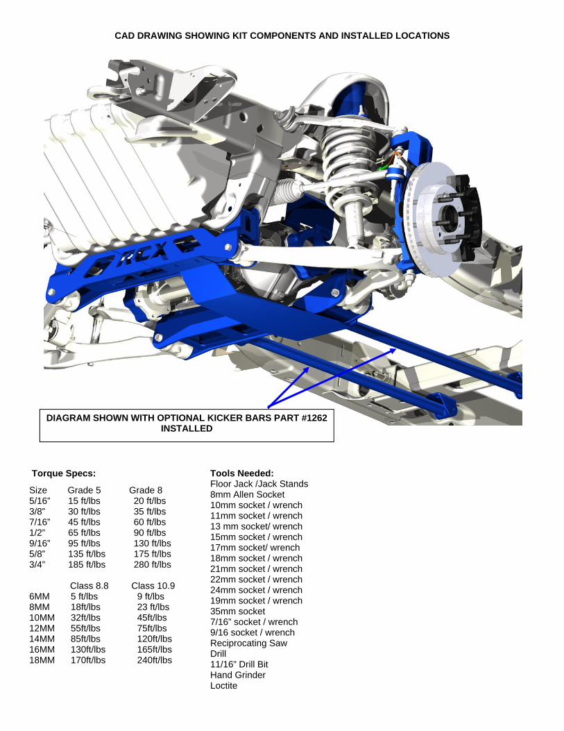
DIAGRAM SHOWN WITH OPTIONAL KICKER BARS PART #1262 INSTALLED
CAD DRAWING SHOWING KIT COMPONENTS AND INSTALLED LOCATIONS
Torque Specs:
Size Grade 5 Grade 8 5/16” 15 ft/lbs 20 ft/lbs 3/8” 30 ft/lbs 35 ft/lbs 7/16” 45 ft/lbs 60 ft/lbs 1/2” 65 ft/lbs 90 ft/lbs 9/16” 95 ft/lbs 130 ft/lbs 5/8” 135 ft/lbs 175 ft/lbs 3/4” 185 ft/lbs 280 ft/lbs Class 8.8 Class 10.9 6MM 5 ft/lbs 9 ft/lbs 8MM 18ft/lbs 23 ft/lbs 10MM 32ft/lbs 45ft/lbs 12MM 55ft/lbs 75ft/lbs 14MM 85ft/lbs 120ft/lbs 16MM 130ft/lbs 165ft/lbs 18MM 170ft/lbs 240ft/lbs
Tools Needed: Floor Jack /Jack Stands 8mm Allen Socket 10mm socket / wrench 11mm socket / wrench 13 mm socket/ wrench 15mm socket / wrench 17mm socket/ wrench 18mm socket / wrench 21mm socket / wrench 22mm socket / wrench 24mm socket / wrench 19mm socket / wrench 35mm socket 7/16” socket / wrench 9/16 socket / wrench Reciprocating Saw Drill 11/16” Drill Bit Hand Grinder Loctite
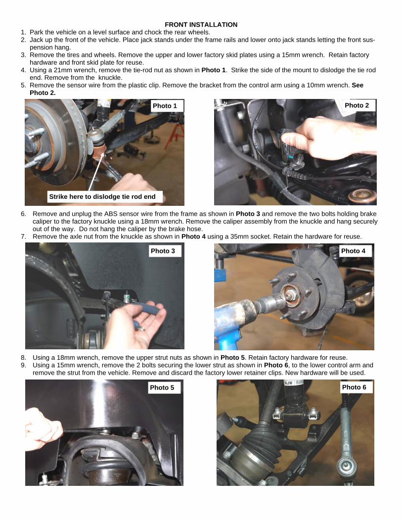
FRONT INSTALLATION 1. Park the vehicle on a level surface and chock the rear wheels. 2. Jack up the front of the vehicle. Place jack stands under the frame rails and lower onto jack stands letting the front sus-
pension hang. 3. Remove the tires and wheels. Remove the upper and lower factory skid plates using a 15mm wrench. Retain factory
hardware and front skid plate for reuse. 4. Using a 21mm wrench, remove the tie-rod nut as shown in Photo 1. Strike the side of the mount to dislodge the tie rod
end. Remove from the knuckle. 5. Remove the sensor wire from the plastic clip. Remove the bracket from the control arm using a 10mm wrench. See
Photo 2.
6. Remove and unplug the ABS sensor wire from the frame as shown in Photo 3 and remove the two bolts holding brake caliper to the factory knuckle using a 18mm wrench. Remove the caliper assembly from the knuckle and hang securely out of the way. Do not hang the caliper by the brake hose.
7. Remove the axle nut from the knuckle as shown in Photo 4 using a 35mm socket. Retain the hardware for reuse.
8. Using a 18mm wrench, remove the upper strut nuts as shown in Photo 5. Retain factory hardware for reuse. 9. Using a 15mm wrench, remove the 2 bolts securing the lower strut as shown in Photo 6, to the lower control arm and
remove the strut from the vehicle. Remove and discard the factory lower retainer clips. New hardware will be used.
Photo 3
Photo 6
Photo 1 Photo 2
Strike here to dislodge tie rod end
Photo 5
Photo 4

10. Remove the sway bar & end links from the lower control arm as shown in Photo 7 using a 15mm wrench. 11. Remove the sway bar from the frame as shown in Photo 8 using a 10mm wrench. Retain all hardware for reuse.
12. Using a 15mm wrench, remove the 6 axle shaft bolts from the differential and remove from the knuckle. Repeat on op-posite side.
13. Remove the upper and lower ball joint from knuckle using a 18mm wrench and 24mm on the lower. Upper shown in Photo 9. Strike the knuckle as shown to dislodge the ball joint. Separate the upper control and lower control arm from the knuckle and remove the knuckle and the lower control arms from the vehicle.
14. Make an alignment mark to show relationship between driveshaft and differential input flange. Using a 11mm wrench, remove the four drive shaft bolts. See Photo 10. Retain hardware for reuse.
15. Place a floor jack under the differential assembly to provide support for following steps.
16. Unplug the electrical connector on differential as shown in Photo 11. 17. Unplug the differential vent hose shown in Photo 12.
Photo 11 Photo 12
Diff Vent Hose
Photo 9 Photo 10
Photo 7 Photo 8
Electrical Plug

18. Remove the four rear cross member bolts and remove the rear cross member brace as shown in Photo 13 using a 18mm wrench.
19. Using a 18mm socket remove the 4 differential bolts (2 each side) securing the differential to the frame. See Photo 14. Retain the hardware for reuse.
20. Slowly lower differential assembly to the ground. 21. Trim the lower control arm mount on the frame as shown in Photo 15. Trim only enough to allow for installation of new
front RCX cross member. 22. Install the front cross member as shown in Photo 16 with the supplied 5/8” x 4 1/2” bolts, nuts /washers. Do not tighten
at this time.
23. On the drivers side rear lower control arm pocket, measure over 3/4” from the edge of the hole on the rear frame where the cross member was removed in step 10 and mark area to be cut as shown in Photo 17. Please note the area needs to be cleaned of any oil, grease and/or undercoating. These coatings can be flammable.
24. Cut area with reciprocating saw as shown in Photo 18.
Photo 13
Cut here
Photo 14
Photo 15 Photo 16
Photo 17 Photo 21
CUT TO MAKE ROOM FOR DIFFERENTIAL

25. After the cross member has been trimmed, grind the edges smooth using a hand grinder, and apply paint to raw metal. 26. Install the Passenger differential drop bracket (open side to center of truck) with the supplied 12mm flange nuts. See
Photo 19. 27. Install the Driver side differential drop bracket (open side to center of truck) with the notch at the bottom to allow
clearance for the differential axle shaft flange using the supplied 12mm x 35mm bolts & washers. Do not tighten. 28. Raise the differential back into place and install on the drivers side drop brackets with the supplied 12mm flange nut and
the factory bolts. See Photo 20. 29. Install the differential to the passenger side drop brackets with the factory nuts and the supplied 12mm x 45mm bolts &
washer on the head of the bolt. The stock nuts/ large washers must be reused to make sure the differential stays located in the drop bracket.
30. Tighten the diff drop brackets (65ft. lbs) to the frame and the differential to the diff drop brackets using a 18mm wrench . 31. Install the rear cross member in the factory location using the supplied 5/8” x 5 1/2” bolts, nuts/ washers as shown in
Photo 21. Do not tighten at this time. 32. Reinstall the lower control arms in the cross member brackets with the factory hardware. Do not tighten at this time. 33. Install the supplied 3/8” studs on the strut spacer using 9/16” wrench & 3/8” nuts to lock the stud in place. See Photo
22. The stud should clinch with about 35-45 ft/lbs of torque. Do not over torque the nut.
34. Install the strut spacer on top of the factory strut as shown in Photo 23 with the stock hardware. Tighten using a 18mm wrench.
Photo 19
PASSENGER SIDE SHOWN DRIVER SIDE SHOWN
Photo 23
Photo 20
Photo 22 Photo 21

35. Trim tie rod ends as per instructions on last page and install on the knuckle. Tighten using a 21mm wrench. 36. Install the strut in the upper strut tower using the supplied 3/8” nuts, washers & lock washers. Tighten using a 9/16”
wrench. 37. Install the lower part of the strut in the factory location on the lower control arm with the supplied 10mm x 55mm bolts,
nuts /washers. Tighten using a 17mm” wrench. 38. On the factory knuckles, remove the bearing assembly using a 15mm wrench and install in the new knuckle. Tighten
hardware. See Photo 24. 39. Install the knuckles on the lower ball joint with the factory hardware and tighten using a 18mm wrench 40. Position the axle shafts in the knuckle and tighten the factory nut using a 35mm socket. Torque to 155 ft-lbs. 41. Install the CV spacer as shown in Photo 25 between the shaft and the differential. Secure with the supplied 10mm x
65mm allen bolts using 8mm allen socket. Use Loctite on the bolt threads and torque to 45ft. Lbs using a crossing pattern.
42. Install the sway bar drop brackets with the 10mm x 35mm bolts, lock washers, and flat washers using a 17mm wrench. Tighten hardware. See Photo 26.
43. Install the sway bar on the sway bar drop brackets with the stock bolts and supplied 10mm nuts & washers. Tighten using a 17mm wrench. See Photo 27.
44. Reinstall the drive shaft on the differential with the stock hardware using a 11mm wrench. Note clocking marked during disassembly.
45. Install the skid plate as shown in Photo 28 with the supplied four 3/8” x 1” bolts, flat washers and lock washers on the front and rear cross member. Tighten using a 9/16 wrench. Tighten cross member hardware using a 24mm wrench.
46. Using the supplied template on last page of instructions as a guide, mark and drill the lower control arm using a 11/16” drill bit to relocate the sway bar end link. See Photo 29. After drilling, install the sway bar end link with the stock hardware and tighten.
Photo 24 Photo 25
Photo 27
Photo 29
Photo 26
Photo 28

47. The brake shroud must be trimmed to allow the caliper to reinstalled, Mark the dust shroud as shown in Photo 30 and trim. Reinstall the brake caliper on the knuckle with the factory hardware and tighten.
48. Slightly pull down on the diff vent hose and reinstall on the differential. See Photo 31. It may be necessary to loosen the diff vent hose from the wire loom to allow for enough slack to reconnect to the axle.
49. Reconnect the electrical connection on the axle that was removed in Step 16.
50. Remove the brake line bracket from the upper control arm mount as shown in Photo 32 using a 13mm wrench. 51. Install the supplied brake line relocation bracket on the upper control arm mount with the stock hardware. Slightly pull
down on the brake line assembly and reinstall on the drop bracket with the supplied 5/16” x 3/4” bolts, nuts /washers using a 7/16 wrench. See Photo 33. Reconnect the ABS wire that was disconnected in Step 6.
52. Remove the brake line clip from the brake line using a flat head screw driver as shown in Photo 34 and trim as shown in Photo 35. Reinstall the modified bracket on the stock control arm with the stock hardware.
53. If the optional kicker bars were purchased with this kit, install at this time per the instructions included with that kit. 54. Reinstall the factory upper skid plate with the factory hardware. 55. Install the tires and wheels. Jack up the front of the vehicle and remove the jack stands. 56. Lower the vehicle to the ground.
Photo 30 Photo 31
Photo 33
Photo 34 Photo 35
Photo 32
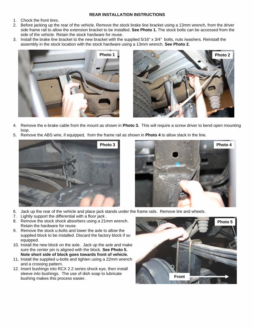
1. Chock the front tires. 2. Before jacking up the rear of the vehicle. Remove the stock brake line bracket using a 13mm wrench, from the driver
side frame rail to allow the extension bracket to be installed. See Photo 1. The stock bolts can be accessed from the side of the vehicle. Retain the stock hardware for reuse.
3. Install the brake line bracket to the new bracket with the supplied 5/16” x 3/4” bolts, nuts /washers. Reinstall the assembly in the stock location with the stock hardware using a 13mm wrench. See Photo 2.
4. Remove the e-brake cable from the mount as shown in Photo 3. This will require a screw driver to bend open mounting loop.
5. Remove the ABS wire, if equipped, from the frame rail as shown in Photo 4 to allow slack in the line.
6. Jack up the rear of the vehicle and place jack stands under the frame rails. Remove tire and wheels. 7. Lightly support the differential with a floor jack . 8. Remove the stock shock absorbers using a 21mm wrench.
Retain the hardware for reuse. 9. Remove the stock u-bolts and lower the axle to allow the
supplied block to be installed. Discard the factory block if so equipped.
10. Install the new block on the axle. Jack up the axle and make sure the center pin is aligned with the block. See Photo 5. Note short side of block goes towards front of vehicle.
11. Install the supplied u-bolts and tighten using a 22mm wrench and a crossing pattern.
12. Insert bushings into RCX 2.2 series shock eye, then install sleeve into bushings. The use of dish soap to lubricate bushing makes this process easier.
REAR INSTALLATION INSTRUCTIONS
Photo 1
Photo 3 Photo 4
?
Photo 2
Photo 5
Front

13. Install the supplied Rough Country 2.2 Series Performance Shock Absorbers in the factory location with factory hardware. Tighten using a 21mm wrench. See Photo 6. Note that these shocks are designed to run piston down as shown.
14. Reconnect the ABS lines to the plastic retaining clip at the bottom of each frame rail. The connector will not be reattached to the top of the frame. Reroute the lines as needed to gain proper slack.
15. Re-install tires and wheels. 16. Remove jack stands and lower vehicle to ground. 17. Place shock decals on shock absorbers and window decal on
vehicle.
TEMPLATE FOR SWAY BAR RELOCATION
Cut out template and position template on lower control arm as shown in Step 45.. Drill with a 11/16 drill bit and relocate the sway bar end links into the new location.
Photo 6

POST INSTALLATION INSTRUCTIONS
1. Check all fasteners for proper torque. Check to ensure for adequate clearance between all rotating, mobile, fixed, and heated members. Verify clearance between exhaust and brake lines, fuel lines, fuel tank, floor boards and wiring har-ness. Check steering gear for clearance. Test and inspect brake system.
2. Perform steering sweep to ensure front brake hoses have adequate slack and do not contact any rotating, mobile or heated members. Inspect rear brake hoses at full extension for adequate slack. Failure to perform hose check/ replace-ment may result in component failure.
3. On some vehicles the front lower skirting will need to be trimmed if using certain wheel /tire combinations and with heavy offset wheels. Trim only as needed.
4. Activate four wheel drive system and check front hubs for engagement. 5. Have a qualified alignment center align the vehicle immediately. Realign to factory specifications. The following are the
recommended specifications: Caster in degrees 4.5 +-1.0 Camber in degrees 0.0—.3 Toe In in degrees 0.1 +-.2 Important note: For alignment purposes, please refer to the instructions above. The inner & outer tie rod ends may need to be trimmed to allow the front end alignment to be set properly. Please alert your alignment specialist of this possibility. 6. Perform head light check and adjustment to proper settings. 7. Check and retighten wheels at 50 miles and again at 500 miles. 8. All kit components must be retightened at 500 miles and then every three thousand miles after installation. Periodically
check all hardware for tightness. 9. Install “Warning to Driver” decal on sun visor Note: Installation of larger tires will require speedometer recalibration.
Thank you for choosing Rough Country for all of your suspension needs.
INSTRUCTIONS FOR TRIMMING TIE ROD ENDS. 1. Disassemble the tie rod from the tie rod ends 2. Measure over 3/8” and mark. 3. Cut the tie rods / tie rod sleeves as shown below to allow the vehicle to be realigned. 4. Smooth any rough edges. 5. Reassemble the cut assembly