06411 mini nucleating bubble engine team members steven nathenson joseph pawelski joaquin pelaez...
TRANSCRIPT

06411 Mini Nucleating Bubble Engine
Team MembersTeam Members
Steven NathensonSteven Nathenson
Joseph PawelskiJoseph Pawelski
Joaquin PelaezJoaquin Pelaez
Andrew PionessaAndrew Pionessa
Brian ThomsonBrian Thomson
Team CoordinatorTeam Coordinator
Dr. WalterDr. Walter
Team MentorsTeam Mentors
Dr. CrassidisDr. Crassidis
Dr. KandlikarDr. Kandlikar
AcknowledgementsAcknowledgements
Steve and Rob in the Machine ShopSteve and Rob in the Machine Shop
Multidisciplinary Engineering Senior DesignMultidisciplinary Engineering Senior Design

Project OverviewProject DescriptionProject Description
– Creation of a mini device that transmits bubble Creation of a mini device that transmits bubble growth into usable motion growth into usable motion
– Current MEMS devices use piezoelectric Current MEMS devices use piezoelectric membrane to convert bubble nucleation to electric.membrane to convert bubble nucleation to electric.
– The project focuses on a larger device in order to The project focuses on a larger device in order to complete the analysis.complete the analysis.
– Periodic bubble nucleation is produced a Periodic bubble nucleation is produced a modulated power supply putting a current through modulated power supply putting a current through a coiled filament.a coiled filament.

Customer Specifications– Keep the design within a 1 foot cube Keep the design within a 1 foot cube – Maintain a budget of $500Maintain a budget of $500– Dimensions within a mm scaleDimensions within a mm scale– Benchmark efficiency of engineBenchmark efficiency of engine– Bubble visualization with high speed cameraBubble visualization with high speed camera– Develop mathematical modelsDevelop mathematical models– Run time of at least 20 secondsRun time of at least 20 seconds– Frequency of at least 5 to 10 Hz.Frequency of at least 5 to 10 Hz.

Risk Assessment
– Engine parts could be too unique and smallEngine parts could be too unique and small• May result in going over budgetMay result in going over budget• May result in lack of timeMay result in lack of time
– The engine design may be to similar to The engine design may be to similar to current MEMS devices if a piston or piston current MEMS devices if a piston or piston like design is not utilizedlike design is not utilized
– Bubbles may be too small to move the Bubbles may be too small to move the piston a significant amount for testingpiston a significant amount for testing

Gantt Chart

Attribute Option 1 Option 2 Option 3 Option 4 Option 5 Option 6
Engine Type Buoyant pistonPartially
Submergedpiston
Submergedcantilever beam
Non-submergedcantilever beam
Rotary w/ ndent
Rotary w/Volumechange
Liquid TypeDe-ionized
waterAlcohol Other ------------- ------------ ------------
Impact Plate Resistant wire Protective plate Other ------------- ------------ ------------
Power SupplyDC power
supplyDC battery AC power supply ------------- ------------ ------------
Heating Element
Straight wire Square wire Circular wire Concentric wire Metal plate ------------
Control System
Stampcontroller
ASIC chipOther
programmable chip------------- ------------ ------------
Cooling System
None Fluid reservoir Heat exchanger ------------- ------------ ------------
Movement Causality
Bubble ImpactBoiling &
Condensation----------------- ------------- ------------ ------------
Electrical System
Pulse widthModulator
(PWM)
AC circuitdesign
DC circuit design ------------- ------------ ------------
Morphological Chart

Concept Feasibility Relative
weight Concept
1 Concept
3 Concept
4 Concept
5 Concept
6 Be Portable 0.079 3 3 3 3 3 Utilize a miniature heating element
0.096 3 3 3 3 3
Be Under Budget 0.011 3 2 2 1 1 Utilize a power supply or a battery
0.073 3 3 3 3 3
Produce a mechanical oscillation
0.084 3 3 3 1 1
Create a millimeter sized engine
0.079 3 2 2 2 2
Protect the heating element
0.118 3 3 3 3 3
Control bubble growth via a control system
0.112 3 3 3 3 3
The liquid reservoir should be cooled
0 3 3 3 3 3
Theoretically prove engine design
0.107 3 3 3 1 1
Create a working engine 0.096 3 2 2 1 1 Test the engine 0.084 3 3 3 3 3 Create a lightweight design
0.062 3 3 3 3 3
Alleviate friction between piston and casing
0.082 3 4 4 4 4
Raw score ---------- 3.249 3.145 3.145 2.656 2.656 Normalized score ---------- 1 0.968 0.968 0.817 0.817
Weighted Average Analysis

Detailed DesignMaterial SelectionMaterial Selection• Piston CasingPiston Casing
– Boroscilicate Glass (Pyrex)Boroscilicate Glass (Pyrex)– Stock part at McMaster - CarrStock part at McMaster - Carr– Machining - glass department is able to cutMachining - glass department is able to cut
• Piston BasePiston Base– Glass Mica Ceramic – high temp Glass Mica Ceramic – high temp – Machining - Mechanical engineering machine shopMachining - Mechanical engineering machine shop
• PistonPiston– Low Density Polyethylene (LDPE)Low Density Polyethylene (LDPE)– Less dense than waterLess dense than water– Core center to promote floatationCore center to promote floatation– Machining - Mechanical Engineering machine shopMachining - Mechanical Engineering machine shop
• ElectrodesElectrodes– Copper Wire - Stock item at McMaster-CarrCopper Wire - Stock item at McMaster-Carr
• Heater ElementHeater Element– Option 1Option 1
• Platinum wire and soldered electrodesPlatinum wire and soldered electrodes– Option 2Option 2
• Manufactured heating elements provided by Dr. KandlikarManufactured heating elements provided by Dr. Kandlikar
Pyrex Glass Casing
Ceramic Mica Base
LDPE Piston
Platinum Wire
Copper Electrodes

Budget
$500$500– PistonPiston– CasingCasing– BaseBase– Heater Heater – Electrical ControlsElectrical Controls
Part # Name Description Quantity Unit Cost Total Cost
1 PistonLow density Polyethelyne, 0.25" OD ± 0.018" x 8 ft., McMaster Carr
#8754K12 8 $0.67 $5.36
2 CasingPyrex tubing, 0.375" ± 0.012" x 0.218" ± 0.028" x 1 ft., McMaster Carr
#8729K33 1 $4.16 $4.163 Base Glass Mica Ceramics, 1/2" OD x 3", McMaster Carr #8499K618 1 $26.35 $26.354 Electrodes Copper wire - .032" (78 ft) (8873K17) Mcmaster-Carr 1 $3.13 $3.135 Heating Element Platinum Wire, 0.008" OD x 0.16437" 1 $0.00 $0.00
$39
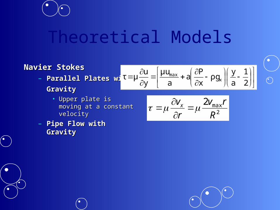
Theoretical Models
Navier StokesNavier Stokes– Parallel Plates with Parallel Plates with
GravityGravity • Upper plate is moving at a Upper plate is moving at a
constant velocityconstant velocity
– Pipe Flow with GravityPipe Flow with Gravity 2
max2
R
rv
r
vx
2
1
a
yρg
x
Pa
a
μu
y
uμτ x
max

Theoretical ModelsSystem ModelsSystem Models
– Factors taken into accountFactors taken into account
– Two model types Two model types • Based upon geometrical relationshipsBased upon geometrical relationships• Based directly off of the Navier-Stokes equationsBased directly off of the Navier-Stokes equations
– 5 total models5 total models• Some neglected forces shown to be insignificantSome neglected forces shown to be insignificant• Some include all forces of the systemSome include all forces of the system
– Verification ModelVerification Model• Simplified version of the modelsSimplified version of the models

B1
B2K1
xp Mp Piston
Mw Water
Systems Model 1Systems Model 1– Second order Second order
approximationapproximation– Negligible forces are Negligible forces are
removed removed – Water displacement is Water displacement is
knownknown– Water moves proportional Water moves proportional
to the displacement of the to the displacement of the bubblebubble
Theoretical Models
B1
B2
B4
xp
xw
mp
mw
B3
K1
Water
Piston
Systems Model 2Systems Model 2– First order approximationFirst order approximation– Neglects the viscous Neglects the viscous
shear force due to the air shear force due to the air on the pistonon the piston
– Water moves proportional Water moves proportional to the displacement of the to the displacement of the bubblebubble
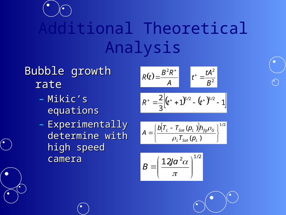
Additional Theoretical Analysis
Bubble growth rateBubble growth rate– Mikic’s equationsMikic’s equations– Experimentally Experimentally
determine with high determine with high speed cameraspeed camera
A
RBtR
2
113
2 2/32/3 ttR
2
2
B
tAt
2/1212
Ja
B
2/1
)(
)(
LSatL
GfgLSatL
pT
hpTTbA

Additional Theoretical Analysis
• Heat TransferHeat Transfer– Transient heat Transient heat
conductionconduction– Semi-infinite solidSemi-infinite solid– For 12 ms pulse, 10 For 12 ms pulse, 10
V and between 2 and V and between 2 and 5 A were applied to 5 A were applied to the entire circuit the entire circuit
– Power = 20 to 50 WPower = 20 to 50 W
t
xerfc
k
xq
t
x
k
tq
TtxT oo
*2**4exp
***2
,"2
2
1
"
x
qo”
T ∞ = 25 C
T s = 400 C
WPower 495.101

Electrical System Requirements
SpecificationsSpecifications– Supply pulse signal with adjustable amplitude, duty cycle, Supply pulse signal with adjustable amplitude, duty cycle,
and frequencyand frequency– Signal must be output continuouslySignal must be output continuously– 100, 72, and 60 W signal for 10, 20 and 30 ms pulse 100, 72, and 60 W signal for 10, 20 and 30 ms pulse – Implement component protection as well as operator Implement component protection as well as operator
protectionprotection– Design for small load resistance (~0.5 Ω)Design for small load resistance (~0.5 Ω)– Flexible for different loadsFlexible for different loads

Final Electrical Design
M1
Vin
0 0
Load
G1
S1
D1
D2
D4
V 5Vdd
0
D3G2
G4
G3S2
Vin
0
V 6Vdd
0
S4
S3
Load
0
M2
0
V 7
Vdd
Load
M3
M4
Vin
0 0
I
PL, VL
PL, VL
I
I
PL, VL
(a) Single NMOS (b) Single PMOS (c) Combined
22 TGSD VVk
I Current for saturation condition
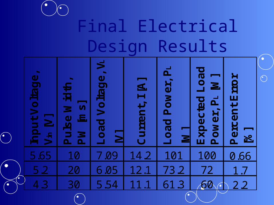
Final Electrical Design ResultsIn
pu
t V
olt
ag
e,
Vin
[V
]
Pu
lse
Wid
th,
PW
[m
s]
Lo
ad
Vo
lta
ge
, V L
[V]
Cu
rre
nt,
I [
A]
Lo
ad
Po
we
r, P
L
[W]
Ex
pe
cte
d L
oa
d
Po
we
r, P
L [
W]
Pe
rce
nt
Err
or
[%]
5.65 10 7.09 14.2 101 100 0.665.2 20 6.05 12.1 73.2 72 1.74.3 30 5.54 11.1 61.3 60 2.2
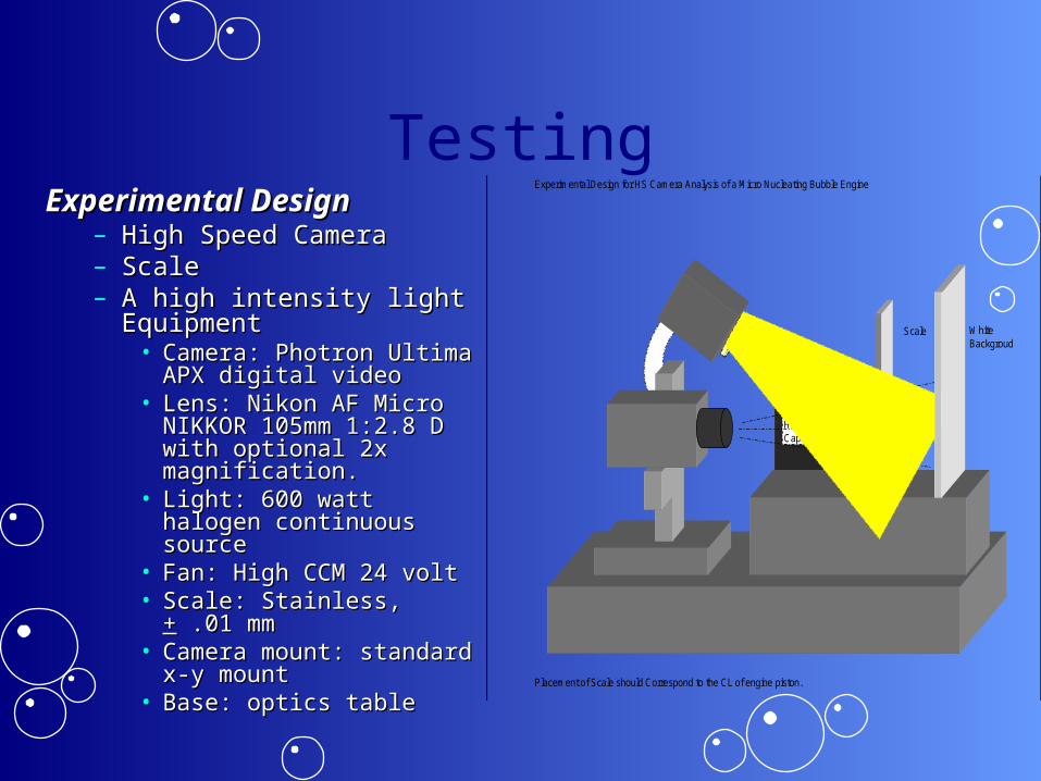
TestingExperimental DesignExperimental Design
– High Speed Camera High Speed Camera – ScaleScale– A high intensity light A high intensity light
EquipmentEquipment• Camera: Photron Ultima Camera: Photron Ultima
APX digital videoAPX digital video• Lens: Nikon AF Micro Lens: Nikon AF Micro
NIKKOR 105mm 1:2.8 D NIKKOR 105mm 1:2.8 D with optional 2x with optional 2x magnification.magnification.
• Light: 600 watt halogen Light: 600 watt halogen continuous sourcecontinuous source
• Fan: High CCM 24 voltFan: High CCM 24 volt• Scale: Stainless, Scale: Stainless, ++ .01 mm .01 mm• Camera mount: standard Camera mount: standard
x-y mountx-y mount• Base: optics tableBase: optics table
Experimental Design for HS Camera Analysis of a Micro Nucleating Bubble Engine
Placement of Scale should Correspond to the CL of engine piston.
High Capacity Fan
Scale
X-Y axis
HS camera
Base
BubbleEngine
WhiteBackgroud
High OutputLight Source

Testing
Wave HeaterWave Heater Coil HeaterCoil Heater

Customer Specifications
• Keep the design within a 1 foot cube Keep the design within a 1 foot cube – Completed: The power supply was reduced in size to maintain Completed: The power supply was reduced in size to maintain
this size requirementthis size requirement• Maintain a budget of $500Maintain a budget of $500
– Used less than $200Used less than $200• Dimensions within a mm scaleDimensions within a mm scale
– The inside diameter of ~5.5 mmThe inside diameter of ~5.5 mm– The height of the piston is 25.4 mmThe height of the piston is 25.4 mm
• Benchmark efficiency of engineBenchmark efficiency of engine– The efficiency has been benchmarked at .07%The efficiency has been benchmarked at .07%
• Bubble visualization with high speed cameraBubble visualization with high speed camera– Video has been takenVideo has been taken
• Develop mathematical modelsDevelop mathematical models• Run time of at least 20 secondsRun time of at least 20 seconds
– Greater than 20 secondsGreater than 20 seconds• Frequency of at least 5 to 10 Hz.Frequency of at least 5 to 10 Hz.
– Approximately 20 Hz.Approximately 20 Hz.

Results
Max displacement of 7 mm Max displacement : 5 mm
Efficiency:

Results