06.06 deaerators
TRANSCRIPT
8/12/2019 06.06 Deaerators
http://slidepdf.com/reader/full/0606-deaerators 1/4
Dairy Processing Handbook/Chapter 6.6 149
Deaerators
Air and gases in milk Milk always contains greater or lesser amounts of air and gases. Thevolume of air in milk in the udder is determined by the air content of thecow’s bloodstream. The oxygen (O
2 ) content is low, being chemically bound
to the hæmoglobin in the blood, while the carbon dioxide (CO2 ) content ishigh because the blood carries large volumes of CO
2 from the cells to the
lungs. The total volume of air in milk in the udder can be from around 4,5 to6 %, of which O
2 constitutes about 0,1 %, N
2 (nitrogen) about 1 % and CO
2
3,5 to 4,9 %.Milk is exposed to air in several ways during milking. Atmospheric
oxygen dissolves in the milk, while CO2is released from it. Part of the air
does not dissolve in the milk but remains in a finely dispersed form, oftenadhering to the fat.
After milking and collection in a churn or cooling tank, the milk maycontain 5,5 to 7,0 % air by volume, with 6 % as an average figure (see Table6.6.1).
The equilibrium that prevails between those three states of aggregation is
determined by temperature and atmospheric pressure. When thetemperature rises, during pasteurisation for instance, dissolved air goesfrom solution to dispersion. It is the dispersed air that causes problems inmilk treatment.
Air in milk occurs in three states:1 Dispersed2 Dissolved3 Chemically bound
Dispersed air causes problems.
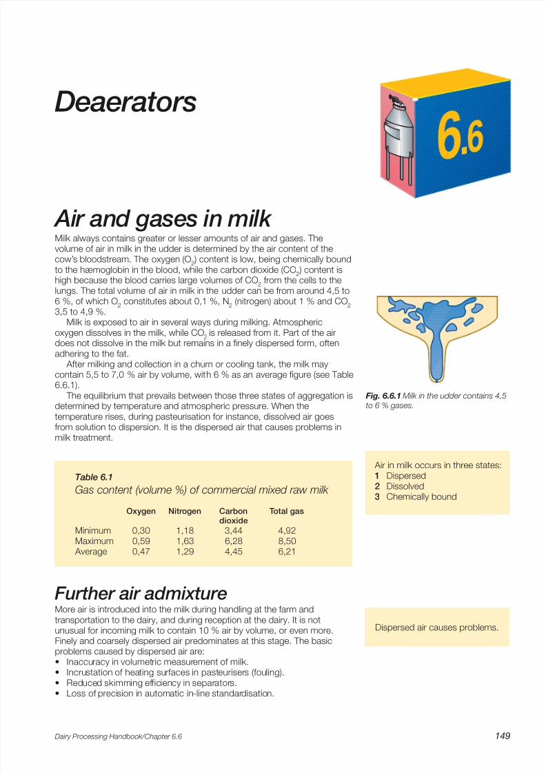
Fig. 6.6.1 Milk in the udder contains 4,5
to 6 % gases.
Table 6.1
Gas content (volume %) of commercial mixed raw milk
Oxygen Nitrogen Carbon Total gasdioxide
Minimum 0,30 1,18 3,44 4,92
Maximum 0,59 1,63 6,28 8,50 Average 0,47 1,29 4,45 6,21
Further air admixtureMore air is introduced into the milk during handling at the farm andtransportation to the dairy, and during reception at the dairy. It is notunusual for incoming milk to contain 10 % air by volume, or even more.Finely and coarsely dispersed air predominates at this stage. The basicproblems caused by dispersed air are:• Inaccuracy in volumetric measurement of milk.• Incrustation of heating surfaces in pasteurisers (fouling).• Reduced skimming efficiency in separators.• Loss of precision in automatic in-line standardisation.
8/12/2019 06.06 Deaerators
http://slidepdf.com/reader/full/0606-deaerators 2/4
Dairy Processing Handbook/Chapter 6.6150
ABC 123
L i t r e s
6 7 8
5 4 3 2 1 9 • Concentration of air in cream, causing– inaccurate in-line fat standardisation,– incrustation of cream heaters,– 'pre-churning' resulting in
- loss of yield in butter production,- adhesion of free fat to the tops of packages.
• Reduction of the stability of cultured milk products (expulsion of whey). Various methods of deaeration are therefore used to avoid jeopardisingproduction and the quality of the products.
Air elimination at collectionWhen milk is collected in road tankers, from churns or bulk cooling tanks,the milk from each farm is normally measured by a volumeter. To optimisemeasuring accuracy, the milk should be passed through an air eliminator just before being measured. Most tankers are therefore provided with an aireliminator through which the farmer’s milk must pass before beingmeasured and pumped aboard the tanker.
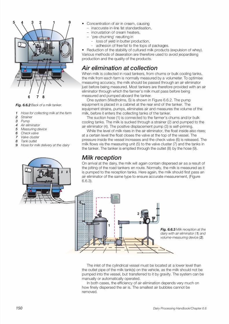
One system (Wedholms, S) is shown in Figure 6.6.2. The pumpequipment is placed in a cabinet at the rear end of the tanker. Theequipment strains, pumps, eliminates air and measures the volume of the
milk, before it enters the collecting tanks of the tanker. The suction hose (1) is connected to the farmer’s churns and/or bulk
cooling tanks. The milk is sucked through a strainer (2) and pumped to theair eliminator (4). The positive displacement pump (3) is self-priming.
While the level of milk rises in the air eliminator, the float inside also rises;at a certain level the float closes the valve at the top of the vessel. Thepressure inside the vessel increases and the check valve (6) is released. Themilk flows via the measuring unit (5) to the valve cluster (7) and the tanks inthe tanker. The tanker is emptied through the outlet (8) by the hose (9).
Milk receptionOn arrival at the dairy, the milk will again contain dispersed air as a result of the jolting of the road tankers en route. Normally, the milk is measured as itis pumped to the reception tanks. Here again, the milk should first pass anair eliminator of the same type to ensure accurate measurement, (Figure6.6.3).
Fig. 6.6.2 Back of a milk tanker.
1 Hose for collecting milk at the farm 2 Strainer
3 Pump
4 Air eliminator 5 Measuring device
6 Check valve7 Valve cluster
8 Tank outlet
9 Hose for milk delivery at the dairy
The inlet of the cylindrical vessel must be located at a lower level thanthe outlet pipe of the milk tank(s) on the vehicle, as the milk should not bepumped into the vessel, but transferred to it by gravity. The system can bemanually or automatically operated.
In both cases, the efficiency of air elimination depends very much onhow finely dispersed the air is. The smallest air bubbles cannot beremoved.
ABC 123
L i t r e s
L i t r e s
2
1
Fig. 6.6.3 Milk reception at thedairy with air eliminator ( 1 ) and
volume-measuring device ( 2 ).

8/12/2019 06.06 Deaerators
http://slidepdf.com/reader/full/0606-deaerators 3/4
Dairy Processing Handbook/Chapter 6.6 151
Vacuum treatment Vacuum deaeration has been used successfully to expel dissolved air andfinely dispersed air bubbles from milk. Pre-heated milk is fed to anexpansion vessel, (Figure 6.6.4), in which the vacuum is adjusted to a levelequivalent to a boiling point about 7 to 8 °C below the pre-heatingtemperature. If the milk enters the vessel at 68 °C, the temperature willimmediately drop to 68 – 8 = 60 °C. The drop in pressure expels the
dissolved air, which boils off, together with a certain amount of the milk. The vapour passes a built-in condenser in the vessel, condenses, and
runs back into the milk, while the boiled-off air, together with non-condensable gases (certain off-flavours) is removed from the vessel by thevacuum pump.
For production of yoghurt the vacuum vessel is not provided with acondenser, as milk intended for yoghurt is often also slightly (15 – 20 %)concentrated. Condensation of vapour is arranged separately.
Deaeration in the milk treatment lineWhole milk is supplied to the pasteuriser and heated to 68 °C. It thenproceeds to the expansion vessel for vacuum treatment. To optimise the
efficiency, the milk enters the vacuum chamber tangentially through a wideinlet, which results in exposure of a thin film on the wall. Expansion of thevapour flashed off from the milk at the inlet accelerates the flow of milk down the wall.
On the way down towards the outlet, which is also located tangentially,the velocity decreases. The feed and discharge capacities are thusidentical. The deaerated milk, now at a temperature of 60 °C, is separated,standardised and homogenised before returning to the pasteuriser for finalheat treatment.
With a separator integrated in the processing line, a flow controller mustbe placed before the separator to maintain a constant flow through thedearator. In this case, the homogeniser must be provided with a circulatingloop. In a process line without a separator, the homogeniser (without a
circulation loop) will maintain the constant flow through the deaerator.
Fig. 6.6.4 Flow of milk and air in
the vacuum deaerator with built-in condenser.
1 Built-in condenser
2 Tangential milk inlet 3 Milk outlet with level control system
Fig. 6.6.5 Milk treatment plant with deaerator.
1 Pasteuriser
2 Deaerator 3 Flow controller
4 Separator
5 Standardisation unit
6 Homogeniser 7 Holding tube8 Booster pump
9 Vacuum pump
2
1
3
Coolingwater
Vacuum
FC
1
2
3
4
5
6
7
8
9
Milk CreamVacuumCooling mediaHeating media

8/12/2019 06.06 Deaerators
http://slidepdf.com/reader/full/0606-deaerators 4/4
Dairy Processing Handbook/Chapter 6.6152