05 engineering and design
DESCRIPTION
k valuesTRANSCRIPT
7
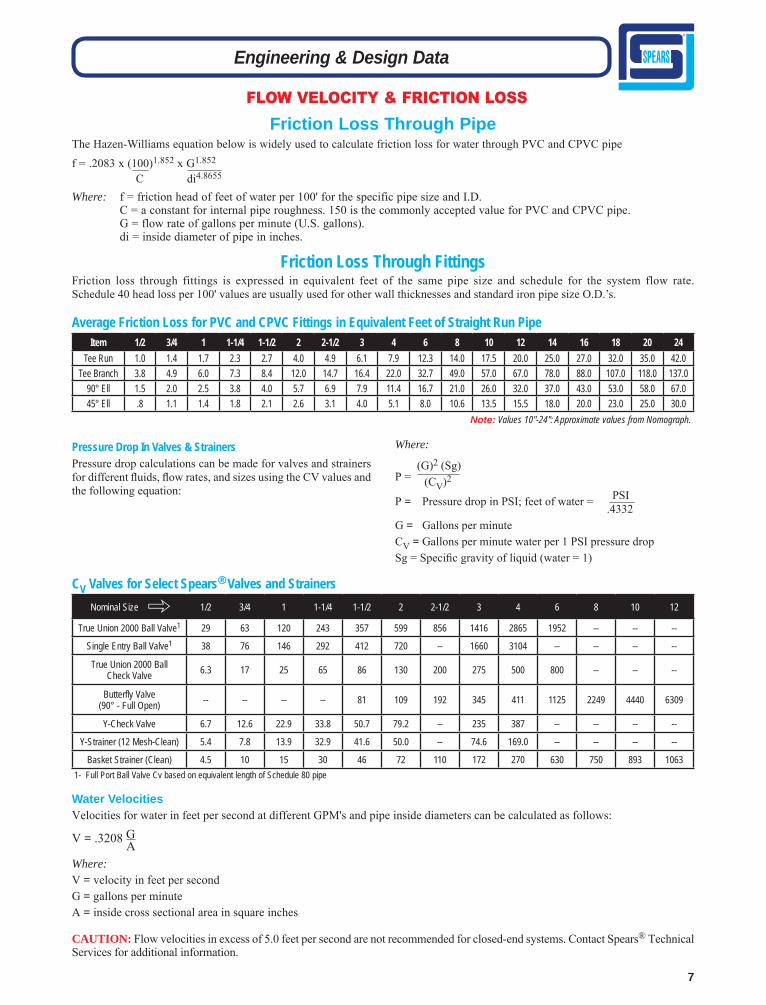
Water VelocitiesVelocities for water in feet per second at different GPM's and pipe inside diameters can be calculated as follows:
Where: V = velocity in feet per secondG = gallons per minuteA = inside cross sectional area in square inches
CAUTION: Flow velocities in excess of 5.0 feet per second are not recommended for closed-end systems. Contact Spears® Technical Services for additional information.
Engineering & Design Data
FLOW VELOCITY & FRICTION LOSS
Friction Loss Through FittingsFriction loss through fittings is expressed in equivalent feet of the same pipe size and schedule for the system flow rate. Schedule 40 head loss per 100' values are usually used for other wall thicknesses and standard iron pipe size O.D.’s.
Item 1/2 3/4 1 1-1/4 1-1/2 2 2-1/2 3 4 6 8 10 12 14 16 18 20 24Tee Run 1.0 1.4 1.7 2.3 2.7 4.0 4.9 6.1 7.9 12.3 14.0 17.5 20.0 25.0 27.0 32.0 35.0 42.0
Tee Branch 3.8 4.9 6.0 7.3 8.4 12.0 14.7 16.4 22.0 32.7 49.0 57.0 67.0 78.0 88.0 107.0 118.0 137.090° Ell 1.5 2.0 2.5 3.8 4.0 5.7 6.9 7.9 11.4 16.7 21.0 26.0 32.0 37.0 43.0 53.0 58.0 67.045° Ell .8 1.1 1.4 1.8 2.1 2.6 3.1 4.0 5.1 8.0 10.6 13.5 15.5 18.0 20.0 23.0 25.0 30.0
Average Friction Loss for PVC and CPVC Fittings in Equivalent Feet of Straight Run Pipe
Note: Values 10"-24": Approximate values from Nomograph.
CV Valves for Select Spears® Valves and Strainers
Pressure Drop In Valves & StrainersPressure drop calculations can be made for valves and strainers for different fl uids, fl ow rates, and sizes using the CV values and the following equation:
Where:
P = Pressure drop in PSI; feet of water = PSI .4332G = Gallons per minuteCV = Gallons per minute water per 1 PSI pressure dropSg = Specifi c gravity of liquid (water = 1)
P = (G)2 (Sg)
(CV)2
V = .3208 G A
Friction Loss Through PipeThe Hazen-Williams equation below is widely used to calculate friction loss for water through PVC and CPVC pipe
f = .2083 x (100)1.852 x G1.852
C di4.8655
Where: f = friction head of feet of water per 100' for the specific pipe size and I.D. C = a constant for internal pipe roughness. 150 is the commonly accepted value for PVC and CPVC pipe. G = flow rate of gallons per minute (U.S. gallons). di = inside diameter of pipe in inches.
Nominal Size 1/2 3/4 1 1-1/4 1-1/2 2 2-1/2 3 4 6 8 10 12
True Union 2000 Ball Valve1 29 63 120 243 357 599 856 1416 2865 1952 -- -- --
Single Entry Ball Valve1 38 76 146 292 412 720 -- 1660 3104 -- -- -- --
True Union 2000 Ball Check Valve 6.3 17 25 65 86 130 200 275 500 800 -- -- --
Butterfly Valve(90° - Full Open) -- -- -- -- 81 109 192 345 411 1125 2249 4440 6309
Y-Check Valve 6.7 12.6 22.9 33.8 50.7 79.2 -- 235 387 -- -- -- --
Y-Strainer (12 Mesh-Clean) 5.4 7.8 13.9 32.9 41.6 50.0 -- 74.6 169.0 -- -- -- --
Basket Strainer (Clean) 4.5 10 15 30 46 72 110 172 270 630 750 893 1063
"
1- Full Port Ball Valve Cv based on equivalent length of Schedule 80 pipe
8
Engineering & Design Data
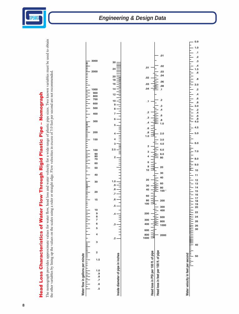
Hea
d Lo
ss C
hara
cter
isti
cs o
f W
ater
Flo
w T
hrou
gh R
igid
Pla
stic
Pip
e –
Nom
ogra
phTh
e no
mog
raph
pro
vide
s app
roxi
mat
e va
lues
for w
ater
fl ow
, hea
d lo
ss a
nd w
ater
vel
ocity
for a
wid
e ra
nge
of p
last
ic p
ipe
size
s. Tw
o kn
own
varia
bles
mus
t be
used
to o
btai
n th
e ot
her v
aria
bles
by
linin
g up
the
valu
es o
n th
e sc
ales
usin
g a
rule
r or s
traig
ht e
dge.
Flo
w v
eloc
ities
in e
xces
s of 5
.0 fe
et p
er se
cond
are
not
reco
mm
ende
d.
9
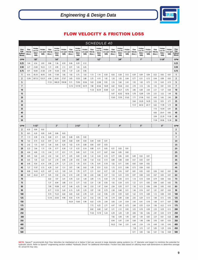
NOTE: Spears® recommends that Flow Velocities be maintained at or below 5 feet per second in large diameter piping systems (i.e. 6" diameter and larger) to minimize the potential for hydraulic shock. Refer to Spears® engineering section entitled "Hydraulic Shock" for additional information. Friction loss data based on utilizing mean wall dimensions to determine average ID; actual ID may vary.
FLOW VELOCITY & FRICTION LOSS
Engineering & Design Data
GPM 1-1/2" 2" 2-1/2" 3" 4" 5" 6" GPM2 0.32 0.04 0.02 2 5 0.81 0.20 0.09 0.49 0.06 0.03 5 7 1.13 0.38 0.16 0.68 0.11 0.05 0.48 0.05 0.02 7
10 1.62 0.73 0.32 0.97 0.21 0.09 0.68 0.09 0.04 0.44 0.03 0.01 10 15 2.42 1.55 0.67 1.46 0.45 0.20 1.02 0.19 0.08 0.66 0.07 0.03 15 20 3.23 2.64 1.15 1.95 0.77 0.34 1.37 0.33 0.14 0.88 0.11 0.05 0.51 0.03 0.01 20 25 4.04 4.00 1.73 2.44 1.17 0.51 1.71 0.49 0.21 1.10 0.17 0.07 0.64 0.05 0.02 25 30 4.85 5.60 2.43 2.92 1.64 0.71 2.05 0.69 0.30 1.32 0.24 0.10 0.77 0.06 0.03 0.49 0.02 0.01 30 35 5.65 7.45 3.23 3.41 2.18 0.94 2.39 0.92 0.40 1.54 0.32 0.14 0.89 0.08 0.04 0.57 0.03 0.01 35 40 6.46 9.54 4.14 3.90 2.79 1.21 2.73 1.18 0.51 1.76 0.41 0.18 1.02 0.11 0.05 0.65 0.04 0.02 40 45 7.27 11.87 5.15 4.39 3.47 1.51 3.07 1.46 0.63 1.99 0.51 0.22 1.15 0.13 0.06 0.73 0.04 0.02 45 50 8.08 14.43 6.25 4.87 4.22 1.83 3.41 1.78 0.77 2.21 0.61 0.27 1.28 0.16 0.07 0.81 0.05 0.02 0.56 0.02 0.01 50 60 9.69 20.22 8.77 5.85 5.92 2.56 4.10 2.49 1.08 2.65 0.86 0.37 1.53 0.23 0.10 0.97 0.08 0.03 0.67 0.03 0.01 60 70 6.82 7.87 3.41 4.78 3.32 1.44 3.09 1.15 0.50 1.79 0.30 0.13 1.14 0.10 0.04 0.79 0.04 0.02 70 75 7.31 8.94 3.88 5.12 3.77 1.63 3.31 1.30 0.56 1.92 0.34 0.15 1.22 0.11 0.05 0.84 0.05 0.02 75 80 7.80 10.08 4.37 5.46 4.25 1.84 3.53 1.47 0.64 2.04 0.39 0.17 1.30 0.13 0.06 0.90 0.05 0.02 80 90 8.77 12.53 5.43 6.15 5.28 2.29 3.97 1.82 0.79 2.30 0.48 0.21 1.46 0.16 0.07 1.01 0.07 0.03 90 100 9.74 15.23 6.60 6.83 6.42 2.78 4.41 2.22 0.96 2.55 0.59 0.25 1.62 0.19 0.08 1.12 0.08 0.03 100 125 12.18 23.03 9.98 8.54 9.70 4.21 5.52 3.35 1.45 3.19 0.89 0.38 2.03 0.29 0.13 1.40 0.12 0.05 125 150 10.24 13.60 5.90 6.62 4.70 2.04 3.83 1.24 0.54 2.43 0.41 0.18 1.68 0.17 0.07 150 175 7.72 6.25 2.71 4.47 1.65 0.72 2.84 0.55 0.24 1.96 0.22 0.10 175 200 8.82 8.00 3.47 5.11 2.12 0.92 3.25 0.70 0.30 2.25 0.29 0.12 200 250 11.03 12.10 5.24 6.39 3.20 1.39 4.06 1.06 0.46 2.81 0.43 0.19 250 300 7.66 4.49 1.95 4.87 1.49 0.65 3.37 0.61 0.26 300 350 8.94 5.97 2.59 5.68 1.98 0.86 3.93 0.81 0.35 350 400 10.22 7.64 3.31 6.49 2.54 1.10 4.49 1.03 0.45 400 450 7.30 3.15 1.37 5.05 1.29 0.56 450 500 8.11 3.83 1.66 5.61 1.56 0.68 500
SCHEDULE 40
Flow Rate
(Gallons/ Minute)
Flow Velocity (ft/sec.)
Friction Loss (Ft.Water/ 100ft)
Friction Loss (psi/
100ft)
Flow Velocity (ft/sec.)
Friction Loss (Ft.Water/ 100ft)
Friction Loss (psi/
100ft)
Flow Velocity (ft/sec.)
Friction Loss (Ft.Water/ 100ft)
Friction Loss (psi/
100ft)
Flow Velocity (ft/sec.)
Friction Loss (Ft.Water/ 100ft)
Friction Loss (psi/
100ft)
Flow Velocity (ft/sec.)
Friction Loss (Ft.Water/ 100ft)
Friction Loss (psi/
100ft)
Flow Velocity (ft/sec.)
Friction Loss (Ft.Water/ 100ft)
Friction Loss (psi/
100ft)
Flow Velocity (ft/sec.)
Friction Loss (Ft.Water/ 100ft)
Friction Loss (psi/
100ft)
Flow Rate
(Gallons/ Minute)
GPM 1/8" 1/4" 3/8" 1/2" 3/4" 1" 1-1/4" GPM0.25 1.64 6.54 2.83 0.86 1.36 0.59 0.46 0.29 0.12 0.25 0.50 3.27 23.60 10.23 1.72 4.90 2.12 0.91 1.04 0.45 0.50 0.75 4.91 50.00 21.68 2.59 10.38 4.50 1.37 2.20 0.96 0.75
1 6.55 85.18 36.93 3.45 17.68 7.66 1.82 3.75 1.63 1.13 1.16 0.50 0.63 0.28 0.12 0.39 0.09 0.04 0.22 0.02 0.01 1 2 13.09 307.52 133.31 6.90 63.82 27.67 3.65 13.55 5.88 2.25 4.19 1.82 1.26 1.03 0.44 0.77 0.31 0.13 0.44 0.08 0.03 2 5 17.25 348.29 150.98 9.11 73.96 32.06 5.63 22.88 9.92 3.16 5.60 2.43 1.93 1.69 0.73 1.10 0.43 0.19 5 7 12.76 137.93 59.79 7.88 42.66 18.49 4.42 10.44 4.53 2.70 3.14 1.36 1.55 0.81 0.35 7
10 11.26 82.59 35.80 6.31 20.21 8.76 3.86 6.08 2.64 2.21 1.57 0.68 10 15 9.47 42.82 18.56 5.78 12.89 5.59 3.31 3.32 1.44 15 20 12.63 72.95 31.63 7.71 21.96 9.52 4.42 5.65 2.45 20 25 9.64 33.20 14.39 5.52 8.55 3.71 25 30 11.57 46.54 20.17 6.62 11.98 5.19 30 35 7.73 15.94 6.91 35 40 8.83 20.41 8.85 40 45 9.94 25.39 11.00 45 50 11.04 30.86 13.38 50

10
NOTE: Spears® recommends that Flow Velocities be maintained at or below 5 feet per second in large diameter piping systems (i.e. 6" diameter and larger) to minimize the potential for hydraulic shock. Refer to Spears® engineering section entitled "Hydraulic Shock" for additional information. Friction loss data based on utilizing mean wall dimensions to determine average ID; actual ID may vary.
FLOW VELOCITY & FRICTION LOSS
Engineering & Design Data
SCHEDULE 40Flow Rate
(Gallons/ Minute)
Flow Velocity (ft/sec.)
Friction Loss (Ft.Water/ 100ft)
Friction Loss (psi/
100ft)
Flow Velocity (ft/sec.)
Friction Loss (Ft.Water/ 100ft)
Friction Loss (psi/
100ft)
Flow Velocity (ft/sec.)
Friction Loss (Ft.Water/ 100ft)
Friction Loss (psi/
100ft)
Flow Velocity (ft/sec.)
Friction Loss (Ft.Water/ 100ft)
Friction Loss (psi/
100ft)
Flow Velocity (ft/sec.)
Friction Loss (Ft.Water/ 100ft)
Friction Loss (psi/
100ft)
Flow Velocity (ft/sec.)
Friction Loss (Ft.Water/ 100ft)
Friction Loss (psi/
100ft)
Flow Velocity (ft/sec.)
Friction Loss (Ft.Water/ 100ft)
Friction Loss (psi/
100ft)
Flow Velocity (ft/sec.)
Friction Loss (Ft.Water/ 100ft)
Friction Loss (psi/
100ft)
Flow Rate
(Gallons/ Minute)
GPM 8" 10" 12” 14” 16” 18” 20” 24” GPM100 0.65 0.02 0.01 100 125 0.81 0.03 0.01 125 150 0.97 0.04 0.02 150 175 1.13 0.06 0.03 175 200 1.29 0.08 0.03 0.82 0.02 0.01 200 250 1.62 0.11 0.05 1.03 0.04 0.02 250 300 1.94 0.16 0.07 1.23 0.05 0.02 300 350 2.27 0.21 0.09 1.44 0.07 0.03 1.01 0.03 0.01 350 400 2.59 0.27 0.12 1.64 0.09 0.04 1.16 0.04 0.02 0.96 0.02 0.01 0.73 0.01 0.01 400 450 2.91 0.34 0.15 1.85 0.11 0.05 1.30 0.05 0.02 1.08 0.03 0.01 0.82 0.02 0.01 450 500 3.24 0.41 0.18 2.05 0.14 0.06 1.44 0.06 0.02 1.19 0.04 0.02 0.91 0.02 0.01 500 750 4.85 0.87 0.38 3.08 0.29 0.12 2.17 0.12 0.05 1.79 0.08 0.03 1.37 0.04 0.02 1.08 0.02 0.01 750 1000 6.47 1.48 0.64 4.10 0.49 0.21 2.89 0.21 0.09 2.39 0.13 0.06 1.83 0.07 0.03 1.45 0.04 0.02 1.16 0.02 0.01 1000 1250 5.13 0.74 0.32 3.61 0.31 0.14 2.99 0.20 0.09 2.29 0.10 0.04 1.81 0.06 0.03 1.45 0.03 0.01 1250 1500 6.15 1.03 0.45 4.33 0.44 0.19 3.58 0.28 0.12 2.74 0.14 0.06 2.17 0.08 0.04 1.74 0.05 0.02 1.21 0.02 0.01 1500 2000 5.78 0.75 0.33 4.78 0.47 0.20 3.66 0.25 0.11 2.89 0.14 0.06 2.32 0.08 0.04 1.61 0.03 0.01 2000 2500 7.22 1.13 0.49 5.97 0.71 0.31 4.57 0.37 0.16 3.61 0.21 0.09 2.91 0.12 0.05 2.01 0.05 0.02 2500 3000 7.17 1.00 0.43 5.49 0.52 0.23 4.34 0.29 0.13 3.49 0.17 0.08 2.41 0.07 0.03 3000 3500 6.40 0.70 0.30 5.06 0.39 0.17 4.07 0.23 0.10 2.81 0.09 0.04 3500 4000 5.78 0.50 0.22 4.65 0.30 0.13 3.21 0.12 0.05 4000 4500 6.50 0.62 0.27 5.23 0.37 0.16 3.62 0.15 0.06 4500 5000 5.81 0.45 0.19 4.02 0.18 0.08 5000 5500 6.39 0.53 0.23 4.42 0.22 0.09 5500 6000 6.97 0.63 0.27 4.82 0.25 0.11 6000 7000 5.62 0.34 0.15 7000 7500 6.03 0.39 0.17 7500 8000 6.43 0.43 0.19 8000 8500 6.83 0.49 0.21 8500

11
FLOW VELOCITY & FRICTION LOSS
Engineering & Design Data
NOTE: Spears® recommends that Flow Velocities be maintained at or below 5 feet per second in large diameter piping systems (i.e. 6" diameter and larger) to minimize the potential for hydraulic shock. Refer to Spears® engineering section entitled "Hydraulic Shock" for additional information. Friction loss data based on utilizing mean wall dimensions to determine average ID; actual ID may vary.
GPM 1-1/2" 2" 2-1/2" 3" 4" 5" 6" GPM1 0.19 0.01 0.01 0.11 0.00 0.00 0.08 0.00 0.00 0.05 0.00 0.00 1 2 0.38 0.05 0.02 0.22 0.02 0.01 0.16 0.01 0.00 0.10 0.00 0.00 2 5 0.96 0.29 0.13 0.56 0.08 0.04 0.39 0.03 0.01 0.25 0.01 0.01 5 7 1.34 0.54 0.24 0.78 0.15 0.07 0.55 0.06 0.03 0.35 0.02 0.01 7
10 1.92 1.05 0.46 1.12 0.30 0.13 0.78 0.12 0.05 0.50 0.04 0.02 10 15 2.87 2.23 0.97 1.67 0.63 0.27 1.17 0.26 0.11 0.75 0.09 0.04 15 20 3.83 3.80 1.65 2.23 1.07 0.47 1.56 0.45 0.19 1.00 0.15 0.07 0.57 0.04 0.02 20 25 4.79 5.74 2.49 2.79 1.63 0.70 1.95 0.68 0.29 1.24 0.23 0.10 0.71 0.06 0.03 25 30 5.75 8.04 3.49 3.35 2.28 0.99 2.34 0.95 0.41 1.49 0.32 0.14 0.85 0.08 0.04 0.54 0.03 0.01 30 35 6.71 10.70 4.64 3.91 3.03 1.31 2.73 1.26 0.55 1.74 0.43 0.18 1.00 0.11 0.05 0.63 0.04 0.02 35 40 7.66 13.71 5.94 4.46 3.88 1.68 3.11 1.62 0.70 1.99 0.54 0.24 1.14 0.14 0.06 0.72 0.05 0.02 40 45 8.62 17.05 7.39 5.02 4.83 2.09 3.50 2.01 0.87 2.24 0.68 0.29 1.28 0.17 0.08 0.81 0.06 0.02 45 50 9.58 20.72 8.98 5.58 5.87 2.54 3.89 2.45 1.06 2.49 0.82 0.36 1.42 0.21 0.09 0.90 0.07 0.03 0.63 0.03 0.01 50 60 11.50 29.04 12.59 6.69 8.22 3.56 4.67 3.43 1.49 2.99 1.15 0.50 1.71 0.30 0.13 1.08 0.10 0.04 0.75 0.04 0.02 60 70 13.41 38.64 16.75 7.81 10.94 4.74 5.45 4.56 1.98 3.48 1.54 0.67 1.99 0.39 0.17 1.26 0.13 0.06 0.88 0.05 0.02 70 75 14.37 43.90 19.03 8.37 12.43 5.39 5.84 5.18 2.25 3.73 1.74 0.76 2.14 0.45 0.19 1.35 0.15 0.06 0.94 0.06 0.03 75 80 15.33 49.48 21.45 8.93 14.01 6.07 6.23 5.84 2.53 3.98 1.97 0.85 2.28 0.51 0.22 1.44 0.16 0.07 1.00 0.07 0.03 80 90 17.24 61.54 26.68 10.04 17.42 7.55 7.01 7.26 3.15 4.48 2.45 1.06 2.56 0.63 0.27 1.62 0.20 0.09 1.13 0.09 0.04 90
100 19.16 74.80 32.42 11.16 21.18 9.18 7.79 8.83 3.83 4.98 2.97 1.29 2.85 0.76 0.33 1.80 0.25 0.11 1.25 0.10 0.04 100 125 23.95 113.07 49.02 13.95 32.02 13.88 9.73 13.34 5.78 6.22 4.49 1.95 3.56 1.16 0.50 2.24 0.38 0.16 1.57 0.16 0.07 125 150 28.74 158.49 68.71 16.74 44.88 19.45 11.68 18.70 8.11 7.47 6.30 2.73 4.27 1.62 0.70 2.69 0.53 0.23 1.88 0.22 0.10 150 175 19.53 59.70 25.88 13.63 24.88 10.79 8.71 8.38 3.63 4.98 2.16 0.93 3.14 0.70 0.30 2.19 0.29 0.13 175 200 22.32 76.45 33.14 15.57 31.86 13.81 9.96 10.73 4.65 5.70 2.76 1.20 3.59 0.90 0.39 2.51 0.37 0.16 200 250 27.90 115.58 50.10 19.47 48.17 20.88 12.44 16.22 7.03 7.12 4.17 1.81 4.49 1.36 0.59 3.13 0.57 0.25 250 300 23.36 67.52 29.27 14.93 22.74 9.86 8.55 5.85 2.54 5.39 1.90 0.83 3.76 0.79 0.34 300 350 9.97 7.78 3.37 6.29 2.53 1.10 4.38 1.05 0.46 350 400 11.39 9.96 4.32 7.18 3.24 1.41 5.01 1.35 0.59 400 450 12.82 12.39 5.37 8.08 4.04 1.75 5.64 1.68 0.73 450 500 8.98 4.90 2.13 6.26 2.04 0.89 500
SCHEDULE 80Flow Rate
(Gallons/ Minute)
Flow Velocity (ft/sec.)
Friction Loss (Ft.Water/ 100ft)
Friction Loss (psi/
100ft)
Flow Velocity (ft/sec.)
Friction Loss (Ft.Water/ 100ft)
Friction Loss (psi/
100ft)
Flow Velocity (ft/sec.)
Friction Loss (Ft.Water/ 100ft)
Friction Loss (psi/
100ft)
Flow Velocity (ft/sec.)
Friction Loss (Ft.Water/ 100ft)
Friction Loss (psi/
100ft)
Flow Velocity (ft/sec.)
Friction Loss (Ft.Water/ 100ft)
Friction Loss (psi/
100ft)
Flow Velocity (ft/sec.)
Friction Loss (Ft.Water/ 100ft)
Friction Loss (psi/
100ft)
Flow Velocity (ft/sec.)
Friction Loss (Ft.Water/ 100ft)
Friction Loss (psi/
100ft)
Flow Rate
(Gallons/ Minute)
GPM 1/8" 1/4" 3/8" 1/2" 3/4" 1" 1-1/4" GPM0.25 2.67 21.47 9.31 1.29 3.57 1.55 0.63 0.63 0.27 0.25 0.50 5.35 77.52 33.60 2.59 12.88 5.58 1.25 2.27 0.98 0.50 0.75 8.02 164.25 71.20 3.88 27.29 11.83 1.88 4.80 2.08 0.75
1 10.69 279.84 121.31 5.17 46.49 20.15 2.51 8.18 3.55 1.48 2.24 0.97 0.78 0.48 0.21 0.47 0.14 0.06 0.26 0.03 0.01 1 2 21.39 1010.21 437.93 10.35 167.84 72.76 5.01 29.54 12.81 2.96 8.08 3.50 1.56 1.73 0.75 0.93 0.49 0.21 0.52 0.12 0.05 2 5 25.87 915.95 397.07 12.53 161.23 69.89 7.39 44.12 19.12 3.91 9.45 4.10 2.33 2.67 1.16 1.30 0.64 0.28 5 7 17.54 300.66 130.34 10.35 82.27 35.66 5.48 17.62 7.64 3.26 4.98 2.16 1.81 1.20 0.52 7
10 14.78 159.26 69.04 7.82 34.11 14.79 4.66 9.65 4.18 2.59 2.32 1.00 10 15 11.74 72.27 31.33 6.99 20.44 8.86 3.89 4.91 2.13 15 20 15.65 123.13 53.38 9.33 34.82 15.09 5.18 8.36 3.62 20 25 11.66 52.64 22.82 6.48 12.64 5.48 25 30 13.99 73.78 31.98 7.77 17.71 7.68 30 35 16.32 98.16 42.55 9.07 23.56 10.21 35 40 18.65 125.70 54.49 10.37 30.17 13.08 40 45 11.66 37.53 16.27 45 50 12.96 45.62 19.77 50 60 15.55 63.94 27.72 60 70 18.14 85.06 36.87 70 75 19.43 96.66 41.90 75 80 20.73 108.93 47.22 80

12
Engineering & Design Data
FLOW VELOCITY & FRICTION LOSS
NOTE: Spears® recommends that Flow Velocities be maintained at or below 5 feet per second in large diameter piping systems (i.e. 6" diameter and larger) to minimize the potential for hydraulic shock. Refer to Spears® engineering section entitled "Hydraulic Shock" for additional information. Friction loss data based on utilizing mean wall dimensions to determine average ID; actual ID may vary.
SCHEDULE 80Flow Rate
(Gallons/ Minute)
Flow Velocity (ft/sec.)
Friction Loss (Ft.Water/ 100ft)
Friction Loss (psi/
100ft)
Flow Velocity (ft/sec.)
Friction Loss (Ft.Water/ 100ft)
Friction Loss (psi/
100ft)
Flow Velocity (ft/sec.)
Friction Loss (Ft.Water/ 100ft)
Friction Loss (psi/
100ft)
Flow Velocity (ft/sec.)
Friction Loss (Ft.Water/ 100ft)
Friction Loss (psi/
100ft)
Flow Velocity (ft/sec.)
Friction Loss (Ft.Water/ 100ft)
Friction Loss (psi/
100ft)
Flow Velocity (ft/sec.)
Friction Loss (Ft.Water/ 100ft)
Friction Loss (psi/
100ft)
Flow Velocity (ft/sec.)
Friction Loss (Ft.Water/ 100ft)
Friction Loss (psi/
100ft)
Flow Velocity (ft/sec.)
Friction Loss (Ft.Water/ 100ft)
Friction Loss (psi/
100ft)
Flow Rate
(Gallons/ Minute)
GPM 8" 10" 12" 14" 16" 18" 20” 24” GPM125 0.89 0.04 0.02 125 150 1.07 0.06 0.02 150 175 1.25 0.07 0.03 175 200 1.43 0.10 0.04 0.91 0.03 0.01 200 250 1.78 0.14 0.06 1.13 0.05 0.02 250 300 2.14 0.20 0.09 1.36 0.07 0.03 300 350 2.50 0.27 0.12 1.59 0.09 0.04 1.12 0.04 0.02 350 400 2.85 0.34 0.15 1.81 0.11 0.05 1.28 0.05 0.02 1.06 0.03 0.01 0.81 0.02 0.01 400 450 3.21 0.43 0.19 2.04 0.14 0.06 1.44 0.06 0.03 1.19 0.04 0.02 0.91 0.02 0.01 450 500 3.57 0.52 0.23 2.27 0.17 0.07 1.60 0.07 0.03 1.33 0.05 0.02 1.01 0.02 0.01 500 750 5.35 1.10 0.48 3.40 0.36 0.16 2.40 0.16 0.07 1.99 0.10 0.04 1.52 0.05 0.02 1.19 0.03 0.01 750 1000 7.13 1.87 0.81 4.53 0.62 0.27 3.20 0.27 0.12 2.65 0.17 0.07 2.02 0.09 0.04 1.59 0.05 0.02 1.29 0.03 0.01 1000 1250 5.66 0.94 0.41 4.00 0.40 0.17 3.31 0.25 0.11 2.53 0.13 0.06 1.99 0.07 0.03 1.61 0.04 0.02 1250 1500 6.80 1.32 0.57 4.80 0.57 0.24 3.98 0.36 0.15 3.03 0.18 0.08 2.39 0.10 0.04 1.93 0.06 0.03 1.34 0.03 0.01 1500 2000 6.40 0.96 0.42 5.30 0.61 0.26 4.04 0.31 0.14 3.18 0.18 0.08 2.57 0.10 0.05 1.78 0.04 0.02 2000 2500 6.63 0.92 0.40 5.05 0.48 0.21 3.98 0.27 0.12 3.22 0.16 0.07 2.23 0.06 0.03 2500 3000 7.95 1.29 0.56 6.06 0.67 0.29 4.78 0.37 0.16 3.86 0.22 0.10 2.67 0.09 0.04 3000 3500 7.07 0.89 0.38 5.57 0.50 0.22 4.50 0.30 0.13 3.12 0.12 0.05 3500 4000 6.37 0.64 0.28 5.15 0.38 0.16 3.56 0.15 0.07 4000 4500 7.16 0.79 0.34 5.79 0.47 0.20 4.01 0.19 0.08 4500 5000 6.43 0.57 0.25 4.45 0.23 0.10 5000 5500 7.08 0.68 0.30 4.90 0.28 0.12 5500 6000 7.72 0.80 0.35 5.34 0.33 0.14 6000 7000 6.23 0.44 0.19 7000 7500 6.68 0.49 0.21 7500 8000 7.12 0.56 0.24 8000 8500 7.57 0.62 0.27 8500

13
Engineering & Design Data
FLOW VELOCITY & FRICTION LOSS
NOTE: Spears® recommends that Flow Velocities be maintained at or below 5 feet per second in large diameter piping systems (i.e. 6" diameter and larger) to minimize the potential for hydraulic shock. Refer to Spears® engineering section entitled "Hydraulic Shock" for additional information. Friction loss data based on utilizing mean wall dimensions to determine average ID; actual ID may vary.
SCHEDULE 120Flow Rate
(Gallons/ Minute)
Flow Velocity (ft/sec.)
Friction Loss (Ft.Water/ 100ft)
Friction Loss (psi/
100ft)
Flow Velocity (ft/sec.)
Friction Loss (Ft.Water/ 100ft)
Friction Loss (psi/
100ft)
Flow Velocity (ft/sec.)
Friction Loss (Ft.Water/ 100ft)
Friction Loss (psi/
100ft)
Flow Velocity (ft/sec.)
Friction Loss (Ft.Water/ 100ft)
Friction Loss (psi/
100ft)
Flow Velocity (ft/sec.)
Friction Loss (Ft.Water/ 100ft)
Friction Loss (psi/
100ft)
Flow Velocity (ft/sec.)
Friction Loss (Ft.Water/ 100ft)
Friction Loss (psi/
100ft)
Flow Velocity (ft/sec.)
Friction Loss (Ft.Water/ 100ft)
Friction Loss (psi/
100ft)
Flow Velocity (ft/sec.)
Friction Loss (Ft.Water/ 100ft)
Friction Loss (psi/
100ft)
Flow Rate
(Gallons/ Minute)
GPM 1/2" 3/4" 1" 1-1/4" 1-1/2" 2" 2-1/2" 3" GPM
1 1.77 3.50 1.52 0.86 0.60 0.26 0.51 0.17 0.07 0.28 0.04 0.02 0.20 0.02 0.01 0.12 0.00 0.00 0.08 0.00 0.00 0.05 0.00 0.00 1
2 3.54 12.62 5.47 1.72 2.16 0.94 1.03 0.62 0.27 0.56 0.14 0.06 0.40 0.06 0.03 0.24 0.02 0.01 0.16 0.01 0.00 0.11 0.00 0.00 2
5 8.86 68.86 29.85 4.29 11.78 5.11 2.57 3.40 1.47 1.41 0.78 0.34 1.01 0.35 0.15 0.60 0.10 0.04 0.41 0.04 0.02 0.27 0.01 0.01 5
7 12.41 128.41 55.67 6.00 21.97 9.52 3.60 6.33 2.75 1.97 1.46 0.63 1.41 0.65 0.28 0.84 0.18 0.08 0.57 0.07 0.03 0.38 0.03 0.01 7
10 17.72 248.59 107.76 8.58 42.53 18.43 5.15 12.26 5.31 2.82 2.83 1.23 2.02 1.26 0.54 1.20 0.36 0.15 0.82 0.14 0.06 0.54 0.05 0.02 10
15 4" 12.87 90.11 39.06 7.72 25.98 11.26 4.23 6.00 2.60 3.03 2.66 1.15 1.80 0.75 0.33 1.22 0.29 0.13 0.81 0.11 0.05 15
20 0.64 0.05 0.02 17.16 153.52 66.55 10.30 44.25 19.18 5.64 10.23 4.43 4.04 4.54 1.97 2.40 1.28 0.56 1.63 0.50 0.22 1.07 0.18 0.08 20
25 0.80 0.08 0.03 12.87 66.90 29.00 7.05 15.46 6.70 5.04 6.86 2.97 3.00 1.94 0.84 2.04 0.76 0.33 1.34 0.27 0.12 25
30 0.96 0.11 0.05 15.45 93.77 40.65 8.46 21.67 9.39 6.05 9.61 4.17 3.60 2.72 1.18 2.45 1.06 0.46 1.61 0.38 0.17 30
35 1.12 0.14 0.06 18.02 124.75 54.08 9.87 28.83 12.50 7.06 12.79 5.54 4.20 3.61 1.57 2.85 1.41 0.61 1.88 0.51 0.22 35
40 1.28 0.19 0.08 20.60 159.75 69.25 11.28 36.92 16.01 8.07 16.37 7.10 4.80 4.63 2.01 3.26 1.80 0.78 2.15 0.65 0.28 40
45 1.44 0.23 0.10 5" 12.69 45.92 19.91 9.08 20.37 8.83 5.40 5.76 2.50 3.67 2.24 0.97 2.42 0.81 0.35 45
50 1.60 0.28 0.12 0.69 0.04 0.02 14.09 55.82 24.20 10.09 24.75 10.73 6.00 7.00 3.03 4.08 2.73 1.18 2.69 0.99 0.43 50
60 1.92 0.39 0.17 0.83 0.05 0.02 16.91 78.24 33.92 12.11 34.70 15.04 7.20 9.81 4.25 4.89 3.82 1.66 3.22 1.39 0.60 60
70 2.24 0.52 0.23 0.97 0.07 0.03 19.73 104.09 45.12 14.12 46.16 20.01 8.40 13.05 5.66 5.71 5.09 2.21 3.76 1.84 0.80 70
75 2.40 0.59 0.26 1.04 0.08 0.03 21.14 118.27 51.27 15.13 52.45 22.74 9.00 14.82 6.43 6.11 5.78 2.51 4.03 2.10 0.91 75
80 2.56 0.67 0.29 1.11 0.09 0.04 22.55 133.29 57.78 16.14 59.11 25.62 9.60 16.71 7.24 6.52 6.51 2.82 4.30 2.36 1.02 80
90 2.88 0.83 0.36 1.25 0.11 0.05 25.37 165.78 71.87 18.16 73.52 31.87 10.81 20.78 9.01 7.34 8.10 3.51 4.84 2.94 1.27 90
100 3.20 1.01 0.44 1.38 0.13 0.06 6" 20.18 89.36 38.74 12.01 25.26 10.95 8.15 9.85 4.27 5.37 3.57 1.55 100
125 4.00 1.53 0.66 1.73 0.20 0.09 0.99 0.05 0.02 25.22 135.09 58.56 15.01 38.18 16.55 10.19 14.89 6.45 6.72 5.40 2.34 125
150 4.80 2.14 0.93 2.08 0.28 0.12 1.19 0.07 0.03 30.26 189.35 82.08 18.01 53.52 23.20 12.23 20.87 9.05 8.06 7.57 3.28 150
175 5.60 2.85 1.24 2.42 0.37 0.16 1.38 0.10 0.04 21.01 71.20 30.86 14.27 27.76 12.04 9.40 10.07 4.36 175
200 6.40 3.65 1.58 2.77 0.48 0.21 1.58 0.12 0.05 24.01 91.17 39.52 16.30 35.55 15.41 10.75 12.89 5.59 200
250 8.00 5.52 2.39 3.46 0.72 0.31 1.98 0.18 0.08 30.01 137.83 59.75 20.38 53.75 23.30 13.43 19.49 8.45 250
300 9.60 7.74 3.36 4.15 1.01 0.44 2.37 0.26 0.11 300
350 11.20 10.30 4.46 4.84 1.34 0.58 2.77 0.34 0.15 350
400 12.80 13.19 5.72 5.54 1.72 0.74 3.16 0.44 0.19 400
450 14.40 16.40 7.11 6.23 2.14 0.93 3.56 0.55 0.24 450
500 6.92 2.60 1.13 3.95 0.67 0.29 500
750 10.38 5.50 2.38 5.93 1.14 0.61 750
1,000 13.84 9.37 4.06 7.91 2.40 1.04 1,000
1,250 9.88 3.63 1.57 1,250
1,500 11.86 5.09 2.21 1,500
2,000 15.81 8.67 3.76 2,000

14
Engineering & Design Data
FLOW VELOCITY & FRICTION LOSS
NOTE: Spears® recommends that Flow Velocities be maintained at or below 5 feet per second in large diameter piping systems (i.e. 6" diameter and larger) to minimize the potential for hydraulic shock. Refer to Spears® engineering section entitled "Hydraulic Shock" for additional information. Friction loss data based on utilizing mean wall dimensions to determine average ID; actual ID may vary.
SDR 11
Flow Rate
(Gallons/ Minute)
Velocity Feet Per
Second
Head Loss Feet of
Water Per 100 Ft.
Pressure Loss PSI
Per 100 Ft.
Velocity Feet Per
Second
Head Loss Feet of
Water Per 100 Ft.
Pressure Loss PSI
Per 100 Ft.
Velocity FeetPer
Second
Head Loss Feet of
Water Per 100 Ft.
Pressure Loss PSI
Per 100 Ft.
Velocity Feet Per
Second
Head Loss Feet of
Water Per 100 Ft.
Pressure Loss PSI
Per 100 Ft.
Velocity Feet Per
Second
Head Loss Feet of
Water Per 100 Ft.
Pressure Loss PSI
Per 100 Ft.
Velocity Feet Per
Second
Head Loss Feet of
Water Per 100 Ft.
Pressure Loss PSI
Per 100 Ft.
Flow Rate
(Gallons/ Minute)
GPM 1⁄2" 3 ⁄4" 1" 1-1⁄4" 1-1⁄2" 2" GPM
1 1.71 3.19 1.38 0.80 0.50 0.22 0.48 0.15 0.06 1
2 3.42 11.53 5.00 1.60 1.82 0.79 0.96 0.53 0.23 2
3 5.13 24.43 10.59 2.40 3.85 1.67 1.44 1.12 0.49 3
4 6.83 41.62 18.04 3.20 6.55 2.84 1.93 1.91 0.83 4
5 8.54 62.91 27.27 4.00 9.91 4.29 2.41 2.89 1.25 5
6 10.25 88.18 38.23 4.79 13.89 6.02 2.89 4.05 1.76 6
7 11.96 117.32 50.86 5.59 18.47 8.01 3.37 5.39 2.34 7
8 13.67 150.23 65.13 6.39 23.66 10.26 3.85 6.90 2.99 8
9 15.38 186.85 81.00 7.19 29.42 12.76 4.33 8.58 3.72 9
10 17.08 227.11 98.45 7.99 35.76 15.50 4.82 10.43 4.52 3.23 3.94 1.71 2.31 1.75 0.76 1.35 0.49 0.21 10
15 11.99 75.78 32.85 7.22 22.11 9.58 4.84 8.35 3.62 3.47 3.71 1.61 2.03 1.03 0.45 15
20 15.98 129.11 55.97 9.63 37.67 16.33 6.46 14.23 6.17 4.63 6.33 2.74 2.70 1.76 0.76 20
25 12.04 56.94 24.69 8.07 21.51 9.33 5.78 9.56 4.15 3.38 2.66 1.15 25
30 14.45 79.82 34.60 9.68 30.15 13.07 6.94 13.40 5.81 4.05 3.73 1.62 30
35 16.86 106.19 46.03 11.30 40.11 17.39 8.09 17.83 7.73 4.73 4.96 2.15 35
40 12.91 51.37 22.27 9.25 22.83 9.90 5.40 6.35 2.75 40
45 14.52 63.89 27.70 10.41 28.40 12.31 6.08 7.89 3.42 45
50 16.14 77.66 33.66 11.56 34.52 14.96 6.75 9.60 4.16 50
55 17.75 92.65 40.16 12.72 41.18 17.85 7.43 11.45 4.96 55
60 13.88 48.38 20.97 8.10 13.45 5.83 60
70 16.19 64.37 27.90 9.46 17.89 7.76 70
80 10.61 22.91 9.93 80
90 12.16 28.50 12.35 90
100 13.51 34.64 15.02 100
125 16.89 52.37 22.70 125
15
Engineering & Design Data
FLOW VELOCITY & FRICTION LOSS
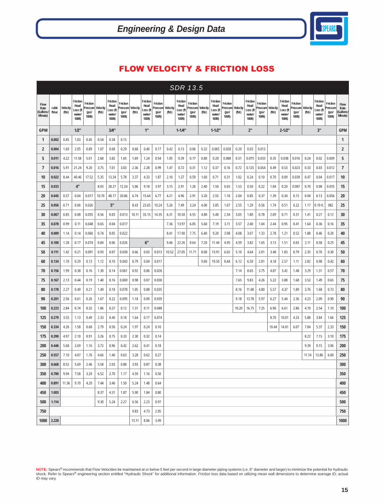
NOTE: Spears® recommends that Flow Velocities be maintained at or below 5 feet per second in large diameter piping systems (i.e. 6" diameter and larger) to minimize the potential for hydraulic shock. Refer to Spears® engineering section entitled "Hydraulic Shock" for additional information. Friction loss data based on utilizing mean wall dimensions to determine average ID; actual ID may vary.
SDR 13.5
Flow Rate
(Gallons/ Minute)
cubic ft/sec
Velocity (ft/s)
Friction Head
Loss (ft water/ 100ft)
Friction Pressure
(psi/ 100ft)
Velocity (ft/s)
Friction Head
Loss (ft water/ 100ft)
Friction Pressure
(psi/ 100ft)
Velocity (ft/s)
Friction Head
Loss (ft water/ 100ft)
Friction Pressure
(psi/ 100ft)
Velocity (ft/s)
Friction Head
Loss (ft water/ 100ft)
Friction Pressure
(psi/ 100ft)
Velocity (ft/s)
Friction Head
Loss (ft water/ 100ft)
Friction Pressure
(psi/ 100ft)
Velocity (ft/s)
Friction Head
Loss (ft water/ 100ft)
Friction Pressure
(psi/ 100ft)
Velocity (ft/s)
Friction Head
Loss (ft water/ 100ft)
Friction Pressure
(psi/ 100ft)
Velocity (ft/s)
Friction Head
Loss (ft water/ 100ft)
Friction Pressure
(psi/ 100ft)
Flow Rate
(Gallons/ Minute)
GPM 1/2" 3/4" 1" 1-1/4" 1-1/2" 2" 2-1/2" 3" GPM
1 0.002 0.85 1.03 0.45 0.54 0.34 0.15 1
2 0.004 1.69 2.05 0.89 1.07 0.68 0.29 0.68 0.40 0.17 0.42 0.13 0.06 0.32 0.065 0.028 0.20 0.03 0.013 2
5 0.011 4.22 11.58 5.01 2.68 3.82 1.65 1.69 1.24 0.54 1.05 0.39 0.17 0.80 0.20 0.088 0.51 0.075 0.033 0.35 0.038 0.016 0.24 0.02 0.009 5
7 0.016 5.91 21.24 9.20 3.75 7.01 3.03 2.36 2.28 0.99 1.47 0.72 0.31 1.12 0.37 0.16 0.72 0.125 0.054 0.49 0.53 0.023 0.33 0.03 0.012 7
10 0.022 8.44 40.46 17.52 5.35 13.34 5.78 3.37 4.33 1.87 2.10 1.37 0.59 1.60 0.71 0.31 1.02 0.24 0.10 0.70 0.09 0.039 0.47 0.04 0.017 10
15 0.033 4" 8.03 28.27 12.24 5.06 9.18 3.97 3.15 2.91 1.26 2.40 1.50 0.65 1.53 0.50 0.22 1.04 0.20 0.087 0.70 0.08 0.035 15
20 0.045 0.57 0.04 0.017 10.70 48.17 20.86 6.74 15.64 6.77 4.21 4.96 2.91 3.20 2.55 1.10 2.04 0.85 0.37 1.39 0.34 0.15 0.94 0.13 0.056 20
25 0.056 0.71 0.06 0.026 5" 8.43 23.65 10.24 5.26 7.49 3.24 4.00 3.85 1.67 2.55 1.29 0.56 1.74 0.51 0.22 1.17 0.19 0. 082 25
30 0.067 0.85 0.08 0.035 0.56 0.03 0.013 10.11 33.15 14.35 6.31 10.50 4.55 4.80 5.40 2.34 3.05 1.80 0.78 2.09 0.71 0.31 1.41 0.27 0.12 30
35 0.078 0.99 0.11 0.048 0.65 0.04 0.017 7.36 13.97 6.05 5.60 7.19 3.11 3.57 2.40 1.04 2.44 0.95 0.41 1.64 0.36 0.16 35
40 0.089 1.14 0.14 0.060 0.74 0.05 0.022 8.41 17.90 7.75 6.40 9.20 3.98 4.08 3.07 1.33 2.78 1.21 0.52 1.88 0.46 0.20 40
45 0.100 1.28 0.17 0.074 0.84 0.06 0.026 6" 9.46 22.26 9.64 7.20 11.44 4.95 4.59 3.82 1.65 3.13 1.51 0.65 2.11 0.58 0.25 45
50 0.111 1.42 0.21 0.091 0.93 0.07 0.030 0.66 0.03 0.013 10.52 27.05 11.71 8.00 13.91 6.02 5.10 4.64 2.01 3.48 1.83 0.79 2.35 0.70 0.30 50
60 0.134 1.70 0.29 0.13 1.12 0.10 0.043 0.79 0.04 0.017 9.60 19.50 8.44 6.12 6.50 2.81 4.18 2.57 1.11 2.82 0.98 0.42 60
70 0.156 1.99 0.38 0.16 1.30 0.14 0.061 0.92 0.06 0.026 7.14 8.65 3.75 4.87 3.42 1.48 3.29 1.31 0.57 70
75 0.167 2.13 0.44 0.19 1.40 0.16 0.069 0.98 0.07 0.030 7.65 9.83 4.26 5.22 3.88 1.68 3.52 1.49 0.65 75
80 0.178 2.27 0.49 0.21 1.49 0.18 0.078 1.05 0.08 0.035 8.16 11.08 4.80 5.57 4.37 1.89 3.76 1.68 0.73 80
90 0.201 2.56 0.61 0.26 1.67 0.22 0.095 1.18 0.09 0.039 9.18 13.78 5.97 6.27 5.44 2.36 4.23 2.09 0.90 90
100 0.223 2.84 0.74 0.32 1.86 0.27 0.12 1.31 0.11 0.048 10.20 16.75 7.25 6.96 6.61 2.86 4.70 2.54 1.10 100
125 0.279 3.55 1.13 0.49 2.33 0.40 0.18 1.64 0.17 0.074 8.70 10.01 4.33 5.88 3.84 1.66 125
150 0.334 4.26 1.58 0.68 2.79 0.56 0.24 1.97 0.24 0.10 10.44 14.01 6.07 7.04 5.37 2.33 150
175 0.390 4.97 2.10 0.91 3.26 0.75 0.33 2.30 0.32 0.14 8.22 7.15 3.10 175
200 0.446 5.68 2.69 1.16 3.72 0.96 0.42 2.62 0.41 0.18 9.39 9.15 3.96 200
250 0.557 7.10 4.07 1.76 4.66 1.46 0.63 3.28 0.62 0.27 11.74 13.86 6.00 250
300 0.668 8.52 5.69 2.46 5.58 2.03 0.88 3.93 0.87 0.38 300
350 0.780 9.94 7.58 3.29 6.52 2.70 1.17 4.59 1.16 0.50 350
400 0.891 11.36 9.70 4.20 7.44 3.46 1.50 5.24 1.48 0.64 400
450 1.003 8.37 4.31 1.87 5.90 1.84 0.80 450
500 1.114 9.30 5.24 2.27 6.56 2.23 0.97 500
750 9.83 4.73 2.05 750
1000 2.228 13.11 8.06 3.49 1000
16
Engineering & Design Data
FLOW VELOCITY & FRICTION LOSS
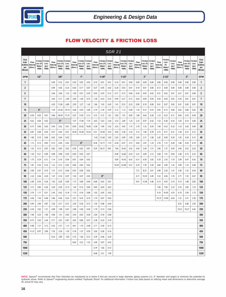
SDR 21
Flow Rate
(Gallons per
Minute)
Flow Velocity (ft/sec.)
Friction Loss (Ft.
Water/ 100ft)
Friction Loss (psi/
100ft)
Flow Velocity (ft/sec.)
Friction Loss (Ft.
Water/ 100ft)
Friction Loss (psi/
100ft)
Flow Velocity (ft/sec.)
Friction Loss (Ft.
Water/ 100ft)
Friction Loss (psi/
100ft)
Flow Velocity (ft/sec.)
Friction Loss (Ft.
Water/ 100ft)
Friction Loss (psi/
100ft)
Flow Velocity (ft/sec.)
Friction Loss (Ft.
Water/ 100ft)
Friction Loss (psi/
100ft)
Flow Velocity (ft/sec.)
Friction Loss (Ft.
Water/ 100ft)
Friction Loss (psi/
100ft)
Flow Velocity (ft/sec.)
Friction Loss (Ft.
Water/ 100ft)
Friction Loss (psi/
100ft)
Flow Velocity (ft/sec.)
Friction Loss (Ft.
Water/ 100ft)
Friction Loss (psi/
100ft)
Flow Rate
(Gallons per
Minute)
GPM 1/2" 3/4" 1" 1-1/4" 1-1/2" 2" 2-1/2" 3" GPM
1 0.49 0.16 0.07 0.30 0.05 0.02 0.19 0.01 0.01 0.14 0.01 0.00 0.09 0.00 0.00 0.06 0.00 0.00 0.04 0.00 0.00 1
2 0.99 0.56 0.24 0.60 0.17 0.07 0.37 0.05 0.02 0.28 0.03 0.01 0.18 0.01 0.00 0.12 0.00 0.00 0.08 0.00 0.00 2
5 2.46 3.06 1.33 1.49 0.91 0.39 0.93 0.29 0.12 0.71 0.15 0.06 0.45 0.05 0.02 0.31 0.02 0.01 0.21 0.01 0.00 5
7 3.45 5.71 2.48 2.09 1.69 0.73 1.30 0.53 0.23 0.99 0.27 0.12 0.63 0.09 0.04 0.43 0.04 0.02 0.29 0.01 0.01 7
10 4.93 11.06 4.80 2.99 3.27 1.42 1.86 1.03 0.45 1.41 0.53 0.23 0.90 0.18 0.08 0.61 0.07 0.03 0.41 0.03 0.01 10
15 4" 7.39 23.44 10.16 4.48 6.93 3.00 2.79 2.18 0.95 2.12 1.12 0.49 1.35 0.37 0.16 0.92 0.15 0.06 0.62 0.06 0.02 15
20 0.50 0.03 0.01 9.86 39.94 17.31 5.97 11.81 5.12 3.72 3.72 1.61 2.83 1.91 0.83 1.80 0.64 0.28 1.23 0.25 0.11 0.83 0.10 0.04 20
25 0.62 0.04 0.02 5" 7.47 17.85 7.74 4.65 5.63 2.44 3.53 2.89 1.25 2.25 0.97 0.42 1.53 0.38 0.16 1.03 0.14 0.06 25
30 0.75 0.06 0.03 0.49 0.02 0.01 8.96 25.02 10.85 5.58 7.89 3.42 4.24 4.05 1.75 2.70 1.35 0.59 1.84 0.53 0.23 1.24 0.20 0.09 30
35 0.87 0.08 0.03 0.57 0.03 0.01 10.45 33.28 14.43 6.51 10.49 4.55 4.94 5.38 2.33 3.15 1.80 0.78 2.15 0.71 0.31 1.44 0.27 0.12 35
40 1.00 0.10 0.04 0.65 0.04 0.02 7.43 13.44 5.83 5.65 6.89 2.99 3.60 2.31 1.00 2.45 0.90 0.39 1.65 0.34 0.15 40
45 1.12 0.13 0.05 0.73 0.04 0.02 6" 8.36 16.71 7.25 6.36 8.57 3.72 4.05 2.87 1.24 2.76 1.12 0.49 1.86 0.43 0.19 45
50 1.25 0.15 0.07 0.82 0.05 0.02 0.58 0.02 0.01 9.29 20.31 8.81 7.06 10.42 4.52 4.50 3.49 1.51 3.06 1.37 0.59 2.06 0.52 0.23 50
60 1.50 0.21 0.09 0.98 0.08 0.03 0.69 0.03 0.01 8.48 14.60 6.33 5.41 4.89 2.12 3.68 1.91 0.83 2.48 0.73 0.32 60
70 1.75 0.29 0.12 1.14 0.10 0.04 0.81 0.04 0.02 9.89 19.43 8.42 6.31 6.50 2.82 4.29 2.55 1.10 2.89 0.97 0.42 70
75 1.87 0.32 0.14 1.22 0.12 0.05 0.86 0.05 0.02 10.59 22.08 9.57 6.76 7.39 3.20 4.60 2.89 1.25 3.09 1.10 0.48 75
80 2.00 0.37 0.16 1.31 0.13 0.06 0.92 0.06 0.02 7.21 8.32 3.61 4.90 3.26 1.41 3.30 1.25 0.54 80
90 2.24 0.46 0.20 1.47 0.16 0.07 1.04 0.07 0.03 8" 8.11 10.35 4.49 5.52 4.06 1.76 3.71 1.55 0.67 90
100 2.49 0.55 0.24 1.63 0.20 0.09 1.15 0.08 0.04 0.68 0.02 0.01 9.01 12.58 5.46 6.13 4.93 2.14 4.13 1.88 0.82 100
125 3.12 0.84 0.36 2.04 0.30 0.13 1.44 0.13 0.06 0.85 0.04 0.02 7.66 7.46 3.23 5.16 2.85 1.23 125
150 3.74 1.17 0.51 2.45 0.42 0.18 1.73 0.18 0.08 1.02 0.05 0.02 9.19 10.45 4.53 6.19 3.99 1.73 150
175 4.36 1.56 0.68 2.86 0.56 0.24 2.01 0.24 0.10 1.19 0.07 0.03 10.73 13.90 6.03 7.22 5.31 2.30 175
200 4.99 2.00 0.87 3.26 0.71 0.31 2.30 0.30 0.13 1.36 0.08 0.04 8.25 6.80 2.95 200
250 6.24 3.02 1.31 4.08 1.08 0.47 2.88 0.46 0.20 1.70 0.13 0.06 10.31 10.27 4.45 250
300 7.48 4.23 1.84 4.90 1.51 0.65 3.45 0.65 0.28 2.04 0.18 0.08 300
350 8.73 5.63 2.44 5.71 2.01 0.87 4.03 0.86 0.37 2.38 0.24 0.10 350
400 9.98 7.21 3.13 6.53 2.57 1.12 4.61 1.10 0.48 2.71 0.30 0.13 400
450 11.22 8.97 3.89 7.35 3.20 1.39 5.18 1.37 0.59 3.05 0.38 0.16 450
500 8.16 3.89 1.69 5.76 1.66 0.72 3.39 0.46 0.20 500
750 8.64 3.52 1.53 5.09 0.97 0.42 750
1000 6.79 1.66 0.72 1000
1250 8.48 2.51 1.09 1250
NOTE: Spears® recommends that Flow Velocities be maintained at or below 5 feet per second in large diameter piping systems (i.e. 6" diameter and larger) to minimize the potential for hydraulic shock. Refer to Spears® engineering section entitled "Hydraulic Shock" for additional information. Friction loss data based on utilizing mean wall dimensions to determine average ID; actual ID may vary.

17
Engineering & Design Data
FLOW VELOCITY & FRICTION LOSS
NOTE: Spears® recommends that Flow Velocities be maintained at or below 5 feet per second in large diameter piping systems (i.e. 6" diameter and larger) to minimize the potential for hydraulic shock. Refer to Spears® engineering section entitled "Hydraulic Shock" for additional information. Friction loss data based on utilizing mean wall dimensions to determine average ID; actual ID may vary.
SDR 26 Flow Rate
(Gallons per
Minute)
Flow Velocity (ft/sec.)
Friction Loss (Ft.
Water/ 100ft)
Friction Loss (psi/
100ft)
Flow Velocity (ft/sec.)
Friction Loss (Ft.
Water/ 100ft)
Friction Loss (psi/
100ft)
Flow Velocity (ft/sec.)
Friction Loss (Ft.
Water/ 100ft)
Friction Loss (psi/
100ft)
Flow Velocity (ft/sec.)
Friction Loss (Ft.
Water/ 100ft)
Friction Loss (psi/
100ft)
Flow Velocity (ft/sec.)
Friction Loss (Ft.
Water/ 100ft)
Friction Loss (psi/
100ft)
Flow Velocity (ft/sec.)
Friction Loss (Ft.
Water/ 100ft)
Friction Loss (psi/
100ft)
Flow Velocity (ft/sec.)
Friction Loss (Ft.
Water/ 100ft)
Friction Loss (psi/
100ft)
Flow Velocity (ft/sec.)
Friction Loss (Ft.
Water/ 100ft)
Friction Loss (psi/
100ft)
Flow Velocity (ft/sec.)
Friction Loss (Ft.
Water/ 100ft)
Friction Loss (psi/
100ft)
Flow Rate
(Gallons per
Minute)
GPM 1" 1-1/4" 1-1/2" 2" 2-1/2" 3" 4" 5" 6" GPM
1 0.30 0.04 0.02 0.18 0.01 0.01 0.14 0.01 0.00 0.09 0.00 0.00 0.06 0.00 0.00 0.04 0.00 0.00 1 2 0.59 0.16 0.07 0.36 0.05 0.02 0.27 0.02 0.01 0.17 0.01 0.00 0.12 0.00 0.00 0.08 0.00 0.00 2 5 1.48 0.88 0.38 0.89 0.26 0.11 0.68 0.13 0.06 0.43 0.04 0.02 0.29 0.02 0.01 0.20 0.01 0.00 5 7 2.07 1.65 0.71 1.25 0.48 0.21 0.95 0.25 0.11 0.61 0.08 0.04 0.41 0.03 0.01 0.28 0.01 0.01 7
10 2.96 3.19 1.38 1.79 0.94 0.41 1.36 0.48 0.21 0.86 0.16 0.07 0.59 0.06 0.03 0.40 0.02 0.01 10 15 4.44 6.76 2.93 2.68 1.98 0.86 2.04 1.02 0.44 1.30 0.34 0.15 0.88 0.13 0.06 0.59 0.05 0.02 15 20 5.91 11.52 4.99 3.57 3.38 1.46 2.72 1.73 0.75 1.73 0.58 0.25 1.18 0.23 0.10 0.79 0.09 0.04 0.48 0.03 0.01 20 25 7.39 17.41 7.55 4.47 5.10 2.21 3.40 2.62 1.14 2.16 0.87 0.38 1.47 0.34 0.15 0.99 0.13 0.06 0.60 0.04 0.02 25 30 8.87 24.40 10.58 5.36 7.15 3.10 4.07 3.67 1.59 2.59 1.23 0.53 1.76 0.48 0.21 1.19 0.18 0.08 0.72 0.05 0.02 0.47 0.02 0.01 30 35 10.35 32.46 14.07 6.25 9.52 4.13 4.75 4.89 2.12 3.03 1.63 0.71 2.06 0.64 0.28 1.39 0.24 0.11 0.84 0.07 0.03 0.55 0.03 0.01 35 40 11.83 41.57 18.02 7.14 12.19 5.28 5.43 6.26 2.71 3.46 2.09 0.90 2.35 0.82 0.35 1.58 0.31 0.14 0.96 0.09 0.04 0.63 0.03 0.01 40 45 8.04 15.16 6.57 6.11 7.78 3.37 3.89 2.60 1.13 2.65 1.02 0.44 1.78 0.39 0.17 1.08 0.11 0.05 0.70 0.04 0.02 45 50 8.93 18.43 7.99 6.79 9.46 4.10 4.32 3.16 1.37 2.94 1.24 0.54 1.98 0.47 0.20 1.19 0.14 0.06 0.78 0.05 0.02 0.55 0.02 0.01 50 60 10.72 25.83 11.20 8.15 13.26 5.75 5.19 4.42 1.92 3.53 1.73 0.75 2.38 0.66 0.29 1.43 0.19 0.08 0.94 0.07 0.03 0.66 0.03 0.01 60 70 9.51 17.64 7.65 6.05 5.88 2.55 4.12 2.30 1.00 2.77 0.88 0.38 1.67 0.26 0.11 1.10 0.09 0.04 0.77 0.04 0.02 70 75 10.19 20.05 8.69 6.49 6.69 2.90 4.41 2.62 1.13 2.97 1.00 0.43 1.79 0.29 0.13 1.17 0.10 0.05 0.83 0.04 0.02 75 80 10.87 22.59 9.79 6.92 7.54 3.27 4.70 2.95 1.28 3.17 1.13 0.49 1.91 0.33 0.14 1.25 0.12 0.05 0.88 0.05 0.02 80 90 8" 12.22 28.10 12.18 7.78 9.37 4.06 5.29 3.67 1.59 3.57 1.40 0.61 2.15 0.41 0.18 1.41 0.15 0.06 0.99 0.06 0.03 90
100 0.65 0.02 0.01 13.58 34.16 14.81 8.65 11.39 4.94 5.88 4.46 1.93 3.96 1.71 0.74 2.39 0.50 0.22 1.56 0.18 0.08 1.10 0.08 0.03 100 125 0.81 0.03 0.01 10.81 17.22 7.47 7.35 6.74 2.92 4.95 2.58 1.12 2.99 0.75 0.33 1.96 0.27 0.12 1.38 0.11 0.05 125 150 0.98 0.04 0.02 8.82 9.45 4.10 5.94 3.62 1.57 3.58 1.06 0.46 2.35 0.38 0.16 1.65 0.16 0.07 150 175 1.14 0.06 0.03 10" 10.29 12.57 5.45 6.93 4.81 2.09 4.18 1.41 0.61 2.74 0.50 0.22 1.93 0.21 0.09 175 200 1.30 0.08 0.03 0.84 0.03 0.01 7.92 6.16 2.67 4.78 1.80 0.78 3.13 0.64 0.28 2.21 0.27 0.12 200 250 1.63 0.11 0.05 1.05 0.04 0.02 9.91 9.31 4.04 5.97 2.72 1.18 3.91 0.97 0.42 2.76 0.42 0.18 250 300 1.95 0.16 0.07 1.26 0.06 0.02 12" 11.89 13.06 5.66 7.17 3.81 1.65 4.69 1.36 0.59 3.31 0.58 0.25 300350 2.28 0.21 0.09 1.47 0.07 0.03 1.04 0.03 0.01 14" 16" 8.36 5.07 2.20 5.48 1.81 0.79 3.86 0.77 0.34 350 400 2.60 0.27 0.12 1.68 0.09 0.04 1.19 0.04 0.02 0.99 0.03 0.01 0.76 0.01 0.01 9.56 6.50 2.82 6.26 2.32 1.01 4.41 0.99 0.43 400 450 2.93 0.34 0.15 1.88 0.12 0.05 1.34 0.05 0.02 1.11 0.03 0.01 0.85 0.02 0.01 10.75 8.08 3.50 7.04 2.89 1.25 4.96 1.23 0.53 450 500 3.25 0.41 0.18 2.09 0.14 0.06 1.49 0.06 0.03 1.23 0.04 0.02 0.95 0.02 0.01 18" 7.82 3.51 1.52 5.52 1.50 0.65 500 750 4.88 0.88 0.38 3.14 0.30 0.13 2.23 0.13 0.06 1.85 0.08 0.04 1.42 0.04 0.02 1.12 0.02 0.01 20" 8.27 3.17 1.38 750 1000 6.51 1.50 0.65 4.19 0.51 0.22 2.98 0.22 0.10 2.47 0.14 0.06 1.89 0.07 0.03 1.49 0.04 0.02 1.21 0.03 0.01 11.03 5.41 2.34 1000 1250 8.13 2.26 0.98 5.23 0.78 0.34 3.72 0.34 0.15 3.09 0.21 0.09 2.36 0.11 0.05 1.87 0.06 0.03 1.51 0.04 0.02 24" 1250 1500 9.76 3.17 1.38 6.28 1.09 0.47 4.47 0.47 0.21 3.70 0.30 0.13 2.84 0.16 0.07 2.24 0.09 0.04 1.81 0.05 0.02 1.26 0.02 0.01 1500 2000 8.38 1.85 0.80 5.95 0.81 0.35 4.94 0.51 0.22 3.78 0.27 0.12 2.99 0.15 0.07 2.42 0.09 0.04 1.68 0.04 0.02 2000 2500 7.44 1.22 0.53 6.17 0.77 0.34 4.73 0.40 0.18 3.73 0.23 0.10 3.02 0.14 0.06 2.10 0.06 0.02 2500 3000 7.41 1.08 0.47 5.67 0.57 0.25 4.48 0.32 0.14 3.63 0.19 0.08 2.52 0.08 0.03 3000 3500 6.62 0.75 0.33 5.23 0.42 0.18 4.23 0.25 0.11 2.94 0.10 0.05 3500 4000 5.97 0.54 0.24 4.84 0.33 0.14 3.36 0.13 0.06 4000 4500 6.72 0.68 0.29 5.44 0.41 0.18 3.78 0.17 0.07 4500 5000 6.05 0.49 0.21 4.20 0.20 0.09 5000 5500 6.65 0.59 0.25 4.62 0.24 0.10 5500 6000 7.26 0.69 0.30 5.04 0.28 0.12 6000 7000 5.88 0.38 0.16 7000 7500 6.30 0.43 0.19 7500 8000 6.72 0.48 0.21 8000 8500 7.14 0.54 0.24 8500

18
Engineering & Design Data
FLOW VELOCITY & FRICTION LOSS
NOTE: Spears® recommends that Flow Velocities be maintained at or below 5 feet per second in large diameter piping systems (i.e. 6" diameter and larger) to minimize the potential for hydraulic shock. Refer to Spears® engineering section entitled "Hydraulic Shock" for additional information. Friction loss data based on utilizing mean wall dimensions to determine average ID; actual ID may vary.
SDR 32.5 Flow Rate (Gallons
per Minute)
Flow Velocity (ft/
sec.)
Friction Loss (Ft.
Water/ 100ft)
Friction Loss (psi/
100ft)
Flow Velocity (ft/
sec.)
Friction Loss (Ft.
Water/ 100ft)
Friction Loss (psi/
100ft)
Flow Velocity (ft/
sec.)
Friction Loss (Ft.
Water/ 100ft)
Friction Loss (psi/
100ft)
Flow Velocity (ft/
sec.)
Friction Loss (Ft.
Water/ 100ft)
Friction Loss (psi/
100ft)
Flow Velocity (ft/
sec.)
Friction Loss (Ft.
Water/ 100ft)
Friction Loss (psi/
100ft)
Flow Velocity (ft/
sec.)
Friction Loss (Ft.
Water/ 100ft)
Friction Loss (psi/
100ft)
Flow Velocity (ft/
sec.)
Friction Loss (Ft.
Water/ 100ft)
Friction Loss (psi/
100ft)
Flow Rate (Gallons
perMinute)
GPM 6" 8" 10" 12" 14" 16" 18" GPM 20 0.21 0.00 0.00 0.13 0.00 0.00 0.08 0.00 0.00 0.06 0.00 0.00 0.05 0.00 0.00 0.04 0.00 0.00 0.03 0.00 0.00 20 40 0.43 0.02 0.01 0.25 0.00 0.00 0.16 0.00 0.00 0.11 0.00 0.00 0.10 0.00 0.00 0.07 0.00 0.00 0.06 0.00 0.00 40 60 0.64 0.02 0.01 0.38 0.00 0.00 0.24 0.00 0.00 0.17 0.00 0.00 0.14 0.00 0.00 0.11 0.00 0.00 0.09 0.00 0.00 60 80 0.85 0.05 0.02 0.50 0.02 0.01 0.32 0.00 0.00 0.23 0.00 0.00 0.19 0.00 0.00 0.15 0.00 0.00 0.12 0.00 0.00 80 100 1.06 0.07 0.03 0.63 0.02 0.01 0.40 0.00 0.00 0.29 0.00 0.00 0.24 0.00 0.00 0.18 0.00 0.00 0.14 0.00 0.00 100 150 1.60 0.14 0.06 0.94 0.05 0.02 0.61 0.02 0.01 0.43 0.00 0.00 0.36 0.00 0.00 0.27 0.00 0.00 0.22 0.00 0.00 150 200 2.13 0.25 0.11 1.26 0.07 0.03 0.81 0.02 0.01 0.57 0.00 0.00 0.48 0.00 0.00 0.36 0.00 0.00 0.29 0.00 0.00 200 250 2.66 0.37 0.16 1.57 0.12 0.05 1.01 0.05 0.02 0.72 0.02 0.01 0.60 0.00 0.00 0.46 0.00 0.00 0.36 0.00 0.00 250 300 3.19 0.53 0.23 1.88 0.14 0.06 1.21 0.05 0.02 0.86 0.02 0.01 0.71 0.02 0.01 0.55 0.00 0.00 0.43 0.00 0.00 300350 3.72 0.72 0.31 2.20 0.21 0.09 1.41 0.07 0.03 1.01 0.02 0.01 0.83 0.02 0.01 0.64 0.00 0.00 0.50 0.00 0.00 350 400 4.26 0.90 0.39 2.51 0.25 0.11 1.62 0.09 0.04 1.15 0.05 0.02 0.95 0.02 0.01 0.73 0.02 0.01 0.58 0.00 0.00 400 450 4.79 1.13 0.49 2.82 0.32 0.14 1.82 0.12 0.05 1.29 0.05 0.02 1.07 0.02 0.01 0.82 0.02 0.01 0.65 0.00 0.00 450 500 5.32 1.36 0.59 3.14 0.37 0.16 2.02 0.14 0.06 1.44 0.05 0.02 1.19 0.05 0.02 0.91 0.02 0.01 0.72 0.00 0.00 500 550 5.85 1.64 0.71 3.45 0.46 0.20 2.22 0.16 0.07 1.58 0.07 0.03 1.31 0.05 0.02 1.00 0.02 0.01 0.79 0.02 0.01 550600 6.38 1.91 0.83 3.77 0.53 0.23 2.42 0.18 0.08 1.72 0.07 0.03 1.43 0.05 0.02 1.09 0.02 0.01 0.86 0.02 0.01 600650 6.91 2.24 0.97 4.08 0.62 0.27 2.63 0.21 0.09 1.87 0.09 0.04 1.55 0.07 0.03 1.19 0.02 0.01 0.94 0.02 0.01 650700 7.45 2.56 1.11 4.39 0.72 0.31 2.83 0.25 0.11 2.01 0.12 0.05 1.67 0.07 0.03 1.28 0.05 0.02 1.01 0.02 0.01 700750 7.98 2.91 1.26 4.71 0.81 0.35 3.03 0.28 0.12 2.15 0.12 0.05 1.79 0.07 0.03 1.37 0.05 0.02 1.08 0.02 0.01 750 800 8.51 3.28 1.42 5.02 0.90 0.39 3.23 0.30 0.13 2.30 0.14 0.06 1.91 0.09 0.04 1.46 0.05 0.02 1.15 0.02 0.01 800850 9.04 3.67 1.59 5.33 1.01 0.44 3.43 0.35 0.15 2.44 0.16 0.07 2.02 0.09 0.04 1.55 0.05 0.02 1.22 0.02 0.01 850900 5.65 1.13 0.49 3.64 0.39 0.17 2.59 0.16 0.07 2.14 0.12 0.05 1.64 0.05 0.02 1.30 0.02 0.01 900950 5.96 1.25 0.54 3.84 0.44 0.19 2.73 0.18 0.08 2.26 0.12 0.05 1.73 0.07 0.03 1.37 0.05 0.02 9501000 6.28 1.36 0.59 4.04 0.46 0.20 2.87 0.21 0.09 2.38 0.14 0.06 1.82 0.07 0.03 1.44 0.05 0.02 1000 1050 6.59 1.50 0.65 4.24 0.51 0.22 3.02 0.23 0.10 2.50 0.14 0.06 1.92 0.07 0.03 `1.51 0.05 0.02 10501100 6.90 1.64 0.71 4.45 0.55 0.24 3.16 0.25 0.11 2.62 0.16 0.07 2.01 0.09 0.04 1.59 0.05 0.02 11001150 4.65 0.60 0.26 3.30 0.25 0.11 2.74 0.16 0.07 2.10 0.09 0.04 1.66 0.05 0.02 11501200 4.85 0.67 0.29 3.45 0.28 0.12 2.86 0.18 0.08 2.19 0.09 0.04 1.73 0.05 0.02 12001250 5.05 0.72 0.31 3.59 0.30 0.13 2.98 0.21 0.09 2.28 0.09 0.04 1.80 0.07 0.03 1250 1300 5.25 0.76 0.33 3.73 0.32 0.14 3.10 0.21 0.09 2.37 0.12 0.05 1.87 0.07 0.03 13001350 5.46 0.83 0.36 3.88 0.35 0.15 3.22 0.23 0.10 2.46 0.12 0.05 1.95 0.07 0.03 13501400 5.66 0.88 0.38 4.02 0.39 0.17 3.33 0.23 0.10 2.55 0.12 0.05 2.02 0.07 0.03 14001450 5.86 0.95 0.41 4.17 0.42 0.18 3.45 0.25 0.11 2.64 0.14 0.06 2.09 0.07 0.03 14501500 6.06 0.99 0.43 4.31 0.44 0.19 3.57 0.28 0.12 2.74 0.14 0.06 2.16 0.09 0.04 1500 1600 6.47 1.13 0.49 4.60 0.48 0.21 3.81 0.30 0.13 2.92 0.16 0.07 2.31 0.09 0.04 16001700 6.87 1.25 0.54 4.88 0.55 0.24 4.05 0.35 0.15 3.10 0.18 0.08 2.45 0.09 0.04 17001800 5.17 0.60 0.26 4.29 0.39 0.17 3.28 0.21 0.09 2.59 0.12 0.05 18001900 5.46 0.67 0.29 4.53 0.42 0.18 3.47 0.23 0.10 2.74 0.12 0.05 19002000 5.74 0.74 0.32 4.76 0.46 0.20 3.65 0.25 0.11 2.88 0.14 0.06 2000 2100 6.03 0.81 0.35 5.00 0.51 0.22 3.83 0.28 0.12 3.03 0.16 0.07 21002200 6.32 0.88 0.38 5.24 0.55 0.24 4.01 0.30 0.13 3.17 0.16 0.07 22002300 6.61 0.97 0.42 5.48 0.60 0.26 4.20 0.32 0.14 3.31 0.18 0.08 23002400 6.89 1.04 0.45 5.72 0.65 0.28 4.38 0.35 0.15 3.46 0.18 0.08 24002500 7.18 1.11 0.48 5.95 0.72 0.31 4.56 0.37 0.16 3.60 0.21 0.09 25002600 7.47 1.20 0.52 6.19 0.76 0.33 4.74 0.39 0.17 3.75 0.23 0.10 26002700 7.76 1.29 0.56 6.43 0.81 0.35 4.92 0.44 0.19 3.89 0.23 0.10 27002800 8.04 1.38 0.60 6.67 0.88 0.38 5.11 0.46 0.20 4.04 0.25 0.11 28002900 8.33 1.48 0.64 6.91 0.92 0.40 5.29 0.48 0.21 4.18 0.28 0.12 29003000 8.62 1.57 0.68 7.15 0.99 0.43 5.47 0.51 0.22 4.32 0.30 0.13 3000 3100 8.90 1.66 0.72 7.38 1.06 0.46 5.65 0.55 0.24 4.47 0.30 0.13 31003200 9.19 1.78 0.77 7.62 1.13 0.49 5.84 0.58 0.25 4.61 0.32 0.14 32003300 7.86 1.18 0.51 6.02 0.62 0.27 4.76 0.35 0.15 33003400 8.10 1.25 0.54 6.20 0.65 0.28 4.90 0.37 0.16 34003500 8.34 1.31 0.57 6.38 0.69 0.30 5.04 0.39 0.17 35003600 8.57 1.38 0.60 6.57 0.74 0.32 5.19 0.42 0.18 36003700 8.81 1.45 0.63 6.75 0.76 0.33 5.33 0.44 0.19 37003800 6.93 0.81 0.35 5.48 0.46 0.20 38003900 7.11 0.85 0.37 5.62 0.48 0.21 39004000 7.30 0.88 0.38 5.76 0.51 0.22 4000 4100 7.48 0.92 0.40 5.91 0.53 0.23 4100 4200 7.66 0.97 0.42 6.05 0.55 0.24 42004300 6.20 0.58 0.25 43004400 6.34 0.60 0.26 44004500 6.49 0.62 0.27 45004600 6.63 0.65 0.28 46004700 6.77 0.67 0.29 4700

19
FLOW VELOCITY & FRICTION LOSS
Engineering & Design Data
SDR 41
Flow Rate (Gallons per
Minute)
Flow Velocity (ft/
sec.)
Friction Loss (Ft.
Water/ 100ft)
Friction Loss
(psi/ 100ft)
Flow Velocity (ft/
sec.)
Friction Loss (Ft.
Water/ 100ft)
Friction Loss
(psi/ 100ft)
Flow Velocity (ft/
sec.)
Friction Loss (Ft.
Water/ 100ft)
Friction Loss
(psi/ 100ft)
Flow Rate (Gallons per
Minute)
GPM 18" GPM
750 1.05 0.02 0.01 750
1000 1.40 0.04 0.02 20" 1000
1250 1.75 0.05 0.02 1.42 0.03 0.01 24" 1250
1500 2.10 0.08 0.03 1.70 0.05 0.02 1.18 0.02 0.01 1500
2000 2.81 0.13 0.06 2.27 0.08 0.03 1.58 0.03 0.01 2000
2500 3.51 0.20 0.08 2.84 0.12 0.05 1.97 0.05 0.02 2500
3000 4.21 0.27 0.12 3.41 0.16 0.07 2.37 0.07 0.03 3000
3500 4.91 0.36 0.16 3.98 0.22 0.09 2.76 0.09 0.04 3500
4000 5.61 0.47 0.20 4.55 0.28 0.12 3.16 0.12 0.05 4000
4500 6.31 0.58 0.25 5.11 0.35 0.15 3.55 0.14 0.06 4500
5000 5.68 0.42 0.18 3.95 0.17 0.08 5000
5500 6.25 0.50 0.22 4.34 0.21 0.09 5500
6000 6.82 0.59 0.26 4.73 0.24 0.11 6000
7000 5.52 0.32 0.14 7000
7500 5.92 0.37 0.16 7500
8000 6.31 0.42 0.18 8000
8500 6.71 0.47 0.20 8500
NOTE: Spears® recommends that Flow Velocities be maintained at or below 5 feet per second in large diameter piping systems (i.e. 6" diameter and larger) to minimize the potential for hydraulic shock. Refer to Spears® engineering section entitled "Hydraulic Shock" for additional information. Friction loss data based on utilizing mean wall dimensions to determine average ID; actual ID may vary.
20
Engineering & Design Data
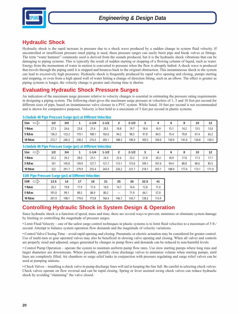
Hydraulic ShockHydraulic shock is the rapid increase in pressure due to a shock wave produced by a sudden change in system fluid velocity. If uncontrolled or insufficient pressure rated piping is used, these pressure surges can easily burst pipe and break valves or fittings. The term “water hammer” commonly used is derived from the sounds produced, but it is the hydraulic shock vibrations that can be damaging to piping systems. This is typically the result of sudden starting or stopping of a flowing column of liquid, such as water. Energy from the momentum of water in motion is converted to pressure when the flow is abruptly halted. A shock wave is produced that travels through the piping until it is stopped and bounces back to the original obstruction. This instantaneous shock to the system can lead to excessively high pressures. Hydraulic shock is frequently produced by rapid valve opening and closing, pumps starting and stopping, or even from a high speed wall of water hitting a change of direction fitting, such as an elbow. The effect is greater as piping systems is longer, the velocity change is greater and closing time is shorter.
Evaluating Hydraulic Shock Pressure SurgesAn indication of the maximum surge pressure relative to velocity changes is essential in estimating the pressure rating requirements in designing a piping system. The following chart gives the maximum surge pressure at velocities of 1, 5 and 10 feet per second for different sizes of pipe, based on instantaneous valve closure in a PVC system. While listed, 10 feet per second is not recommended and is shown for comparative purposes. Velocity is best held to a maximum of 5 feet per second in plastic systems.
Schedule 40 Pipe Pressure Surge (psi) at Different VelocitiesSize 1/2 3/4 1 1-1/4 1-1/2 2 2-1/2 3 4 6 8 10 12
1 ft/sec 27.3 24.6 23.8 21.6 20.5 18.8 19.7 18.4 16.9 15.1 14.2 13.5 13.0
5 ft/Sec 136.3 123.2 119.1 108.1 102.6 94.2 98.5 91.8 84.5 75.4 70.8 67.4 65.2
10 ft/sec 272.7 246.3 238.2 216.3 205.1 188.3 196.9 183.5 169.0 150.9 141.6 134.8 130.5
Schedule 80 Pipe Pressure Surge (psi) at Different VelocitiesSize 1/2 3/4 1 1-1/4 1-1/2 2 2-1/2 3 4 6 8 10 12
1 ft/sec 32.2 29.2 28.0 25.5 24.3 22.6 23.2 21.8 20.3 18.9 17.8 17.3 17.1
5 ft/Sec 161 145.8 139.9 127.7 121.7 113.1 115.8 109.1 101.6 94.4 88.8 86.6 85.5
10 ft/sec 322 291.7 279.9 255.4 243.4 226.2 231.7 218.1 203.1 188.9 177.6 173.1 171.0
SDR Pipe Pressure Surge (psi) at Different VelocitiesSDR 13.5 14 17 18 21 25 26 32.5 41
1 ft/sec 20.2 19.8 17.9 17.4 16.0 14.7 14.4 12.8 11.4
5 ft/Sec 101.0 99.1 89.5 86.9 80.2 --- 71.9 64.1 57.0
10 ft/sec 201.9 198.1 179.0 173.8 160.4 146.7 143.7 128.2 113.9
Controlling Hydraulic Shock in System Design & OperationSince hydraulic shock is a function of speed, mass and time, there are several ways to prevent, minimize or eliminate system damage by limiting or controlling the magnitude of pressure surges.• Limit Fluid Velocity – one of the safest surge control techniques in plastic systems is to limit fluid velocities to a maximum of 5 ft./ second. Attempt to balance system operation flow demands and the magnitude of velocity variations.• Control Valve Closing Time – avoid rapid opening and closing. Pneumatic or electric actuation may be considered for greater control. Use of multi-turn or gear operated valves may also be beneficial in slowing valve opening and closing. When all valves and controls are properly sized and adjusted, surges generated by changes in pump flows and demands can be reduced to non-harmful levels.• Control Pump Operation – operate the system to maintain uniform pump flow rates. Use slow starting pumps where long runs and larger diameters are downstream. Where possible, partially close discharge valves to minimize volume when starting pumps, until lines are completely filled. Air chambers or surge relief tanks in conjunction with pressure regulating and surge relief valves can be used at pumping stations. • Check Valves – installing a check valve in pump discharge lines will aid in keeping the line full. Be careful in selecting check valves. Check valves operate on flow reversal and can be rapid closing. Spring or lever assisted swing check valves can reduce hydraulic shock by avoiding “slamming” the valve closed.
""
"

21
Thermal Expansion & Contraction Piping systems expand and contract with changes in temperature. Thermoplastic piping expands and contracts more than metallic piping when subjected to temperature changes – as much as ten times that of steel. The effects of thermal expansion and contrac-tion must be considered during the design phase, particularly for systems involving long runs, hot water lines, hot drain lines, and piping systems exposed to environmental temperature extremes. Installation versus working temperature or summer to winter extremes must be considered and addressed with appropriate system design to prevent damage to the piping system.
120
160
140
180
200
100
80
60
40
20
0
2200 1/16 1/8 3/16 1/4 5/16 3/8 7/16 1/2 9/16 5/8 11/16 3/4 13/16 7/8 15/16 1 1-1/16 1-1/8 1-3/16 1-1/4
1120SPEARS® PVC
4120SPEARS® CPVC
2110SPEARS® CLEAR™ PVC
Change in Length (inches) of a 10' Length of Pipe
0.100 0.20 0.30 0.40 0.50 0.60 0.70 0.80 0.90 1.00 1.10 1.20
Highly important is the change in length of plastic pipe with temperature variation. This fact should always be considered when installing pipe lines and allowances made accordingly.
Tem
pera
ture
Ris
e or
Dro
p, ˚F
The data furnished herein is based on information furnished by manufacturers of the raw material. This information may be considered as a basis for recommendation, but not as a guarantee. Materials should be tested under actual service to determine suitability for a particular purpose.
The degree of movement (change in length) generated as the result of temperature changes, must be calculated based on the type of piping material and the anticipated temperature changes of the system. The rate of expansion does not vary with pipe size. This movement must then be compensated for by the con-struction of appropriate sized expansion loops, offsets, bends or the installation of expansion joints. This absorbs the stresses generated, minimizing damage to the piping.
The following chart depicts the amount of linear movement (change in length, inches) experienced in a 10 ft length of pipe when exposed to various temperature changes.
Engineering & Design Data

22
Calculating Linear Movement Caused by Thermal ExpansionThe change in length caused by thermal expansion or contraction can be calculated as follows:
∆L = 12 yl (∆T)
Where:∆L = expansion or contraction in inchesy = Coeffi cient of linear expansion of piping material selected l = length of piping run in feet∆T = (T1 - T2) temperature change °F Where:T1 = maximum system temperature of system andT2 = system temperature
Coefficient of Linear Expansion (y) of Various Spears®
Piping Products (in/in/°F) per ASTM D 696
Pipe Material yPVC Pressure Pipe (all schedules & SDR’s) and PVC Duct 2.9 x 10⁻⁵ CPVC Schedule 40 & Schedule 80 Pressure Pipe 3.2 x 10⁻⁵
CPVC Duct 3.2 x 10⁻⁵
CTS CPVC Plumbing Pipe 3.2 x 10⁻⁵
Clear PVC Schedule 40 & Schedule 80 Pipe 4.1 x 10⁻⁵
Spears® Low Extractable UPW Pipe 3.9 x 10⁻⁵
Example 2: 100 foot straight run of 2" Schedule 80 CPVC pipe operating temperature 180°F; installed at 80°F∆L = 12 yl (∆T) Where:∆L = linear expansion or contraction in inchesy = 3.2 x 10⁻⁵ in/in/°Fl = 100 ft∆T = 100°F (180°F - 80°F)∆L = 12 in/ft x 0.000032 in/in/ft x 100ft x 100°F∆L = 3.84"In this example the piping would expand approximately 4" in length over a 100 ft straight run once the operating temperature of 180°F was obtained.
Compensating for Movement Caused byThermal Expansion/ContractionThermal expansion/ contraction are usually absorbed by the sys-tem at changes of direction. Long, straight runs are more suscep-tible to measurable movement with changes in temperature and the installation of an expansion joints, expansion loops or offsets is required. This will allow the system to absorb expansion/con-traction forces without damage.Once the change in length (∆L) has been determined, the length of an offset, expansion loop, or bend can be calculated as follows:
ℓ = 3ED (∆L) 2SWhere:ℓ = Length of expansion loop in inchesE = Modulus of elasticityD = Average outside diameter of pipe∆L = Change in length of pipe due to temperature changeS = Working stress at max. temperature∆L = 12 in/ft x 0.000029 in/in/ft x 100 ft x 41°F∆L = 1.43"
Example 1: Calculate the change in length for a 100 foot straight run of 2" Schedule 80 PVC pipe operating at a temperature of 73°F; installed at 32°F.∆L = 12 yl (∆T)Where:∆L = linear expansion or contraction in inches y = 2.9 x 10⁻⁵ in/in/°Fl = 100ft∆T = 41°F (73°F – 32°F)l = Length of expansion loop in inchesE = Modulus of elasticityD = Average outside diameter of pipe∆L = Change in length of pipe due to temperature changeS = Working stress at max. temperature∆L = 12 in/ft x 0.000029 in/in/ft x 100 ft x 41°F∆L = 1.43"In this example the piping would expand approximately 1-1/2" in length over a 100 ft straight run once the operating temperature of 73°F was obtained.
Loop Offset Bend
2/5
6" min.
6" min.1/5
1/2
1/4
1/4 Change of Direction
Long Pipe Run
Engineering & Design Data

23
Hangers or guides should only be placed in the loop, offset, or change of direction as indicated above, and must not compress or restrict the pipe from axial movement. Piping supports should restrict lateral movement and should direct axial movement into the expansion loop configuration. Do not restrain “change in direction” configurations by butting up against joists, studs, walls or other structures. Use only solvent-cemented connections on straight pipe lengths in combination with 90° elbows to construct the expansion loop, offset or bend. The use of threaded components to construct the loop configuration is not recommended. Expansion loops, offsets, and bends should be installed as nearly as possible at the midpoint between anchors. Concentrated loads such as valves should not be installed in the developed length. Calculated sup-port guide spacing distances for offsets and bends must not exceed recommended hanger support pacing for the maximum anticipated temperature. If that occurs, the distance between anchors will have
Thermal StressCompressive stress in piping restrained from expanding can damage the piping system and in some cases damage hangers and supports. The amount of stress generated is dependent on the pipe material’s coefficient of thermal expansion and its ten-sile modulus using the following equation:S = Ey∆TWhere:S = stress induced in the pipeE = Modulus of Elasticity at maximum system temperature y = Coefficient of thermal expansion∆T = total temperature change of the systemThe stress induced must not exceed the pipe material maximum allowable working stress (fiber stress). Increases in temperature will reduce the allowable stress as shown the table.Example: 100 foot straight run of 2" Schedule 80 CPVC pipe operating temperature 180°F; installed at 80°F:∆L = 12 yl (∆T) Where:∆L = linear expansion or contraction in inchesy = 3.2 x 10⁻⁵ in/in/°Fl = 100ft∆T = 100°F (180°F - 80°F)∆L = 12 in/ft x 0.000032 in/in/ft x 100 ft x 100°F∆L = 3.84"The piping would expand approximately 4" in length in a 100 ft straight runThe equation for determining induced stress can then be used:S = Ey∆TWhere:S = stress induced in the pipeE = Modulus of Elasticity at 180°F = 214,000
y = Coefficient of thermal expansion = 3.2 x 10⁻⁵ in./in./°F∆T = total temperature change of the system = 100°FS = 214,000 x .000032 x 100S = 685 psiFrom chart, maximum allowable stress for CPVC at 180°F is 500 psi; Stress generated from this expansion in a restrained piping system exceeds the maximum allowable stress and will result in failure of the piping, unless compensation is made for thermal expansion.
Engineering & Design Data
to be reduced until the support guide spacing distance is equal to or less than the maximum recommended support spacing distance for the appropriate pipe size at the temperature used.Example: 2" Schedule 80 CPVC pipe operating temperature 180°F; installed at 80°F where ∆L = 4.08"ℓ = 3ED (∆L) 2Sℓ = 3 x 360,000 x 2.375 x 4.08 2 x 500ℓ = 102.29"2/5 ℓ = 40.92"1/5 ℓ = 20.46"
Temp (°F)Maximum Allowable
Working (Fiber) Stress, psi
Tensile Modulus of Elasticity, psi
PVC
73 2,000 400,00080 1,760 396,000 90 1,500 375,000 100 1,240 354,000 110 1,020 333,000 120 800 312,000130 620 291,000140 440 270,000
CPVC
73 2,000 364,00090 1,820 349,000 100 1,640 339,000 110 1,500 328,000 120 1,300 316,000 140 1,000 290,000160 750 262,000180 500 214,000200 400 135,000
Maximum Allowable Working (Fiber) Stress and Tensile Modulus at Various Temperatures
2/5
6" min.
6" min.
1/5
Hanger or Guide
20.45"
102.29"40.92"

24
Thrust BlockingThrust blocking prevents pipe movement when a pressure system is activated and pressurized. Thrust blocking is required at all points of change of direction in the pipe line. Most blocking is done where a fitting, valve, or hydrant is installed. There may be times when side blocking is necessary because of curvature occurring without the use of fittings. Usually good compacted backfill will provide the necessary anchor for side thrust. Concrete blocking is the most commonly recommended method of blocking. Concrete is placed directly on the fitting against the line of thrust. The concrete must also pour against undisturbed earth. The size of the blocking will vary with the size of pipe, working pressure exerted, type of fitting, degree of flow direction change, and the soil conditions. PVC and CPVC pipe are flexible and may pulsate under pressure variations. This does not harm the pipe or that part which is enclosed in concrete. It may cause wear at the interface of the concrete block and the backfill. For this reason, pipe and fittings should be wrapped with a one mill or heavier plastic sheeting prior to being embedded in concrete to prevent any possible damage.
THRUST BLOCKING – Water under pressure exerts thrust forces in piping systems. Thrust blocking should be provided, as necessary, to prevent movement of pipe or appurtenances in response to thrust.
Types Of Thrust Blocking:
If thrusts due to high pressure are expected, anchor valves as below. At vertical bends anchor to resist outward thrusts.
1. Thru line connection, tee 2. Thru line connection, cross used as tee 3. Direction change, elbow 4. Change line size, reducer 5. Direction change, tee used as elbow 6. Direction change, cross used as elbow 7. Direction change 8. Thru line connection, wye 9. Valve anchor10. Direction change vertical, bend anchor11. End Caps (above or below ground)
Thrust Blocking Is Required Wherever The Pipeline:* Changes direction (e.g., tees, bends, elbows and crosses)* Changes size at its reducers* Stops, as at dead ends* Valves and hydrants, at which thrust develops when closed.
Size And Type Of Thrust Blocking Depends On:* Maximum system pressure* Pipe size* Type and size of fittings or appurtenance* Line profile (horizontal or vertical bends)* Soil type
See additional information under Installation Gasketed Pipe
Engineering & Design Data

25
Engineering & Design Data
1 psi = 2.036 inches of mercury* SDR Pipe carries the same collapse ratings for all sizes due to the wall thickness/O.D. ratio
Critical Collapse PressuresThe Critical Collapse Pressure is directly related to the pipe wall thickness and represents the maximum allowable external load. External loads can result from conditions such as buried pipe soil loads; underwater applications; vacuum service; and pipe installed on pump suction lines. The actual external load being applied to the pipe is the difference between the external pressure and the internal pressure. As a result, a pressurized pipe can withstand a greater external load than an empty pipe.
Critical Collapse Pressure Rating of Various PVC and CPVC Pipe & Duct @ 73°F with No Safety Factor in PSI (Inches of Water)
Size(in.) Duct SDR 41 SDR 26 SDR 21 SCH 40 SCH 80 SCH 120
2 N/A 17* (470)
74* (2,048)
126* (3,487)
316 (8,746)
939 (25,989)
1309 (36,230)
2-1/2 N/A 17* (470)
74* (2,048)
126* (3,487)
451 (12,483)
975 (26,986)
1309 (36,230)
3 N/A 17* (470)
74* (2,048)
126* (3,487)
307 (8,497)
722 (19,983)
1128 (31,221)
3-1/2 N/A 17* (470)
74* (2,048)
126* (3,487)
217 (6,006)
578 (15,998) N/A
4 N/A 17* (470)
74* (2,048)
126* (3,487)
190 (5,259)
451 (12,482)
1128 (31,221)
5 N/A 17* (470)
74* (2,048)
126* (3,487)
117 (3,238)
361 (10,000) N/A
6 N/A (470)
17* (2,048)
74* (3,487)
126* (2,491)
90 (9,493)
343 (19,983) 722
6 x 1/8 5.2 (144) N/A N/A N/A N/A N/A N/A
6 x 3/16 0.7 (426) N/A N/A N/A N/A N/A N/A
8 10.0 (193)
17* (470)
74* (2,048)
126* (3,487)
58 (1,605)
235 (6,504) N/A
10 5.4 (100)
17* (470)
74* (2,048)
126* (3,487)
49 (1,605)
217 (6,504) N/A
12 3.0 (60)
17* (470)
74* (2,048)
126* (3,487)
42 (1,162)
199 (5,508) N/A
14 2.5 (45)
17* (470)
74* (2,048)
126* (3,487)
40 (1,107)
194 (5,369) N/A
16 1.6 (30)
17* (470)
74* (2,048)
126* (3,487)
40 (1,107)
181 (5,010) N/A
18 1.0 (26)
17* (470)
74* (2,048)
126* (3,487)
33(913)
162 (4,484) N/A
20 1.3 (28)
17* (470)
74* (2,048)
126* (3,487)
28 (775)
157 (4,346) N/A
24 1.0 (20)
17* (470)
74* (2,048)
126* (3,487)
25(692)
150 (4,152) N/A
De-Rating Factors
Standard temperature de-rating factors must be applied for use at elevated temperatures (see following Temperature Limitations sec-tion). Multiply the collapse pressure rating @ 73°F from the chart by the appropriate material de-rating factor.Solvent-cemented connections are preferred over threaded or flanged joining in vacuum applications to reduce potential for leaks.
Appropriate temperature de-rating factors must be applied at tem-peratures other than 73°F based on the material selected.Multiply the collapse pressure rating of the selected pipe at 73°F, by the appropriate de-rating factor to determine the collapse pressure rating of the pipe at the elevated temperature chosen.
PVC & CPVCThe maximum operating temperature for PVC pipe is 140°F and the maximum operating pressure for CPVC pipe is 200°F. As tem-peratures increase, impact strength typically increases while tensile strength and pipe stiffness decrease resulting in reduced applicable pressure ratings. Physical properties of PVC and CPVC pipe are generally specified at 73°F per applicable ASTM material test standards. The maximum allowable pressure at elevated tempera-tures is determined by multiplying the 73°F pressure rating by the applicable material de-rating factor for the elevated use temperature shown in the following chart:
Temperature Limitations
WeatherabilityWhen standard rigid PVC or CPVC pipe is exposed to UV radiation from sunlight the following conditions have been noted:• A color change, slight increase in tensile strength, slight increase in modulus of tensile elasticity, and a slight decrease in impact strength may occur.• Material directly exposed to UV radiation results in extremely shallow penetration depths (frequently less than 0.001 inch).• The effects of UV exposure do not continue when exposure to UV is terminated.• The effects of UV exposure do not penetrate even thin shields such as paint coatings, or wrapping.It is recommended that PVC and CPVC piping products exposed to the direct affects of sunlight be painted with a light colored acrylic or latex paint that is chemically compatible with the PVC/CPVC products. Check with paint manufacture for compatibility. Oil-based paints should NOT be used.Additional consideration should be given to the affects of expan-sion/contraction caused by heat absorption from sunlight in outdoor applications.
PVC Pipe CPVC Pipe
Temp (°F)
Working De-Rating
FactorTemp (°F)
Working De-Rating
Factor73 1.00 73-80 1.0080 0.88 90 0.9190 0.75 100 0.82
100 0.62 110 0.72110 0.51 120 0.65120 0.40 130 0.57130 0.31 140 0.50140 0.22 150 0.42--- --- 160 0.40--- --- 170 0.29--- --- 180 0.25--- --- 200 0.20