05. autodesk revit & parametric...
TRANSCRIPT
Design Computing
05. Autodesk Revit & Parametric Modeling
4/2/2015Digital Design I | HOM3034 | Spring 2015 | Every Thursday 2:00 p.m. – 5:50 pm
Jin Kook Lee, Ph.D. 02-2220-2645 | [email protected] Professor, Space & Design IT Lab.Department of Interior Architecture Design, Hanyang University
+

What to do today: 1 Revit file of CHE Bldg. & several screenshot jpg files
Lecture: 1) Review, 2) BIM & Parametric Modeling Demos
Lab Exercises: A CHE Building Modeling using Revit
1. Lab Exercise 1: Wall Object – Exterior and Interior wall in Revit and its property “screen shot”
2. Lab Exercise 2: Door & Window Object – Door/Window in Revit and its property “screen shot”
3. Lab Exercise 3: Stair Object and others – Components in Revit “screen shot”
4. Lab Exercise 4: Space Object – Room in Revit and its property “screen shot”
5.
Lab Exercise 5: Floor Object – Floor in Revit and its property “myName_LE5_L5.rvt”
6. Lab Exercise 6: Section view “screen shot”
7. Lab Exercise 7: Building Elevation – How to create an entire building floors in elevation view “screen shot”
8. Lab Exercise 8: Editing each floor (Elaborated) “myName_LE7_CHE_bldg.rvt”
Preview: Various BIM Applications
9. Lab Exercise 9: Schedule – Room schedule in Revit “screen shot”
10. Lab Exercise 10: Exporting Revit model – Geometry models & IFC “FBX file and IFC file” from your CHE bldg.
Floor Plan CAD file from floor plan views, 3D CAD file from 3D views, etc.


Review: BIM & Design Visualization
Still “designers” people need 3d visualization
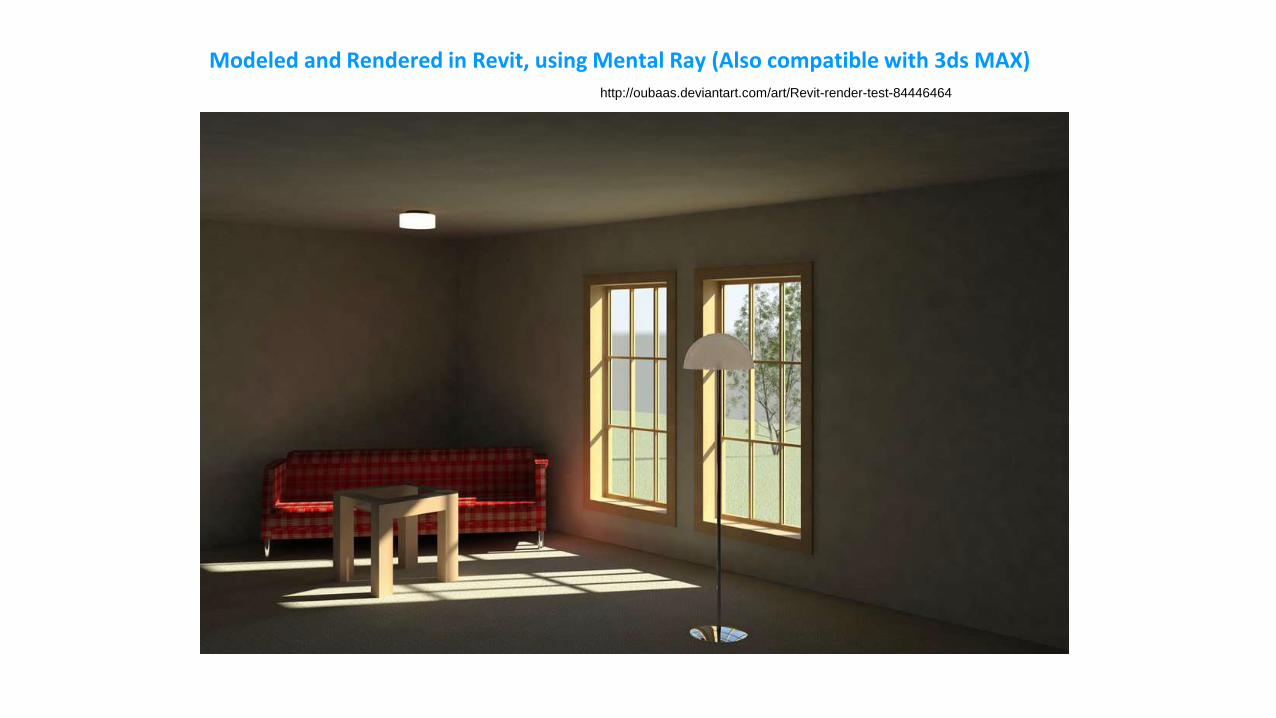
Modeled and Rendered in Revit, using Mental Ray (Also compatible with 3ds MAX)http://oubaas.deviantart.com/art/Revit-render-test-84446464

http://www.revitcity.com/forum_files/26537_banking_hall_1.jpg
Modeled and Rendered in Revit, using Mental Ray (Also compatible with 3ds MAX)

Recommended: Use Revit & MAX for better photo-realistic rendering images
Revit:
MAX:

Rendered by Mental Ray on Revit – Photo-realistic rendering
http://grevity.blogspot.kr/2011/09/beam-me-up-scotty.html

Rendered by Mental Ray on Revit – Photo-realistic rendering
http://grevity.blogspot.kr/2011/09/beam-me-up-scotty.html

http://grevity.blogspot.kr/2011/09/beam-me-up-scotty.html


Review: Autodesk HomeStyler.com
- A web-based parametric modeling tool (& Mobile-based)
- Login using Google Account, and design your room

Autodesk HomeStyler – www.homestyler.com

Autodesk HomeStyler – www.homestyler.com

CAD vs. BIM
- Export your design in .DWG, and .RVT in HomeStyler.com
- Comparison between .DWG file and .RVT

HomeStyler Model is
not a simple CAD
but a simple BIM
This is a “Door” object
Not a rectangle geometry
File – Save As:
JPG, DWG, RVT

AutoCAD DWG file
Object: “Polylines block”
Properties:
Color, Layer, Linetype,
Position X, Y, Z…
Revit RVT file
Object: “Double-Panel Door”
Properties:
Sill height, Frame Type, Material,
Finish, Head height…
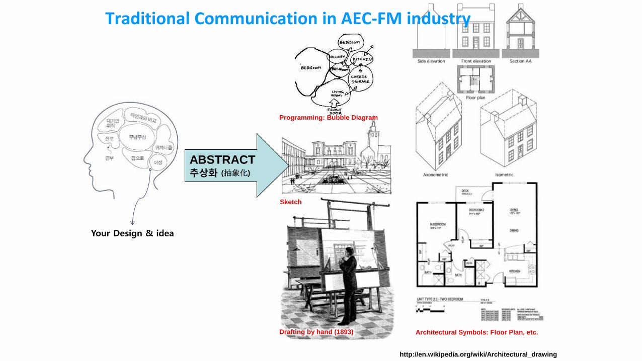
Your Design & idea
http://en.wikipedia.org/wiki/Architectural_drawing
ABSTRACT추상화 (抽象化)
Programming: Bubble Diagram
Sketch
Drafting by hand (1893) Architectural Symbols: Floor Plan, etc.
Traditional Communication in AEC-FM industry

Let computers do this abstract, visualization, symbolization, etc.
AutoCAD
- This is a geometric line object
- Only geometric properties
- Computer does NOT know this is
a “Door”
- Only “drawing” & “visualization”
- Any CAD tools can draw this wall,
using Rhino, 3ds Max, SketchUP,
even by this PowerPoint
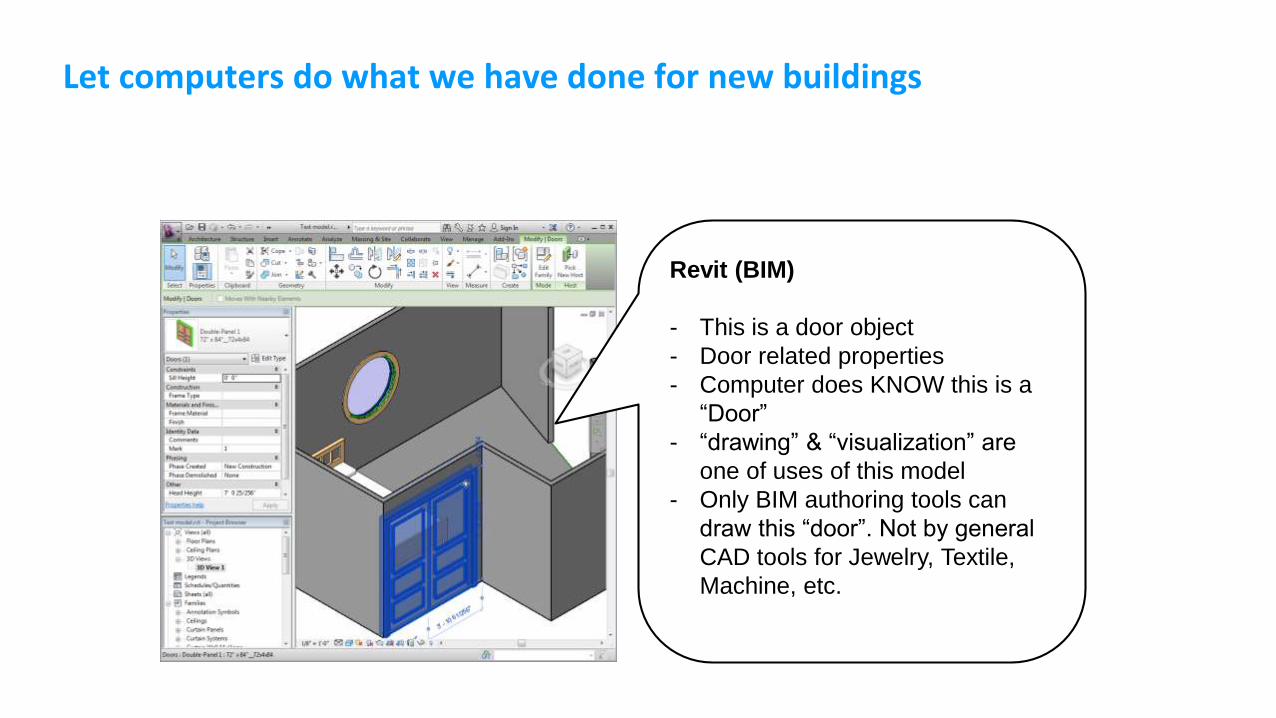
Let computers do what we have done for new buildings
Revit (BIM)
- This is a door object
- Door related properties
- Computer does KNOW this is a
“Door”
- “drawing” & “visualization” are
one of uses of this model
- Only BIM authoring tools can
draw this “door”. Not by general
CAD tools for Jewelry, Textile,
Machine, etc.

Conventional Design Computing
Drafting
Modeling
Rendering
Animation
… Visualizations
Focusing on geometric shapes
Let computers do what we have drawn

New direction of Design Computing: Information Modeling
Focusing on information
Let computers do what we have done

Review: Solid Modeling in Revit

Basic 3d geometric modeling supported by Revit

Basic 3d geometric modeling supported by Revit
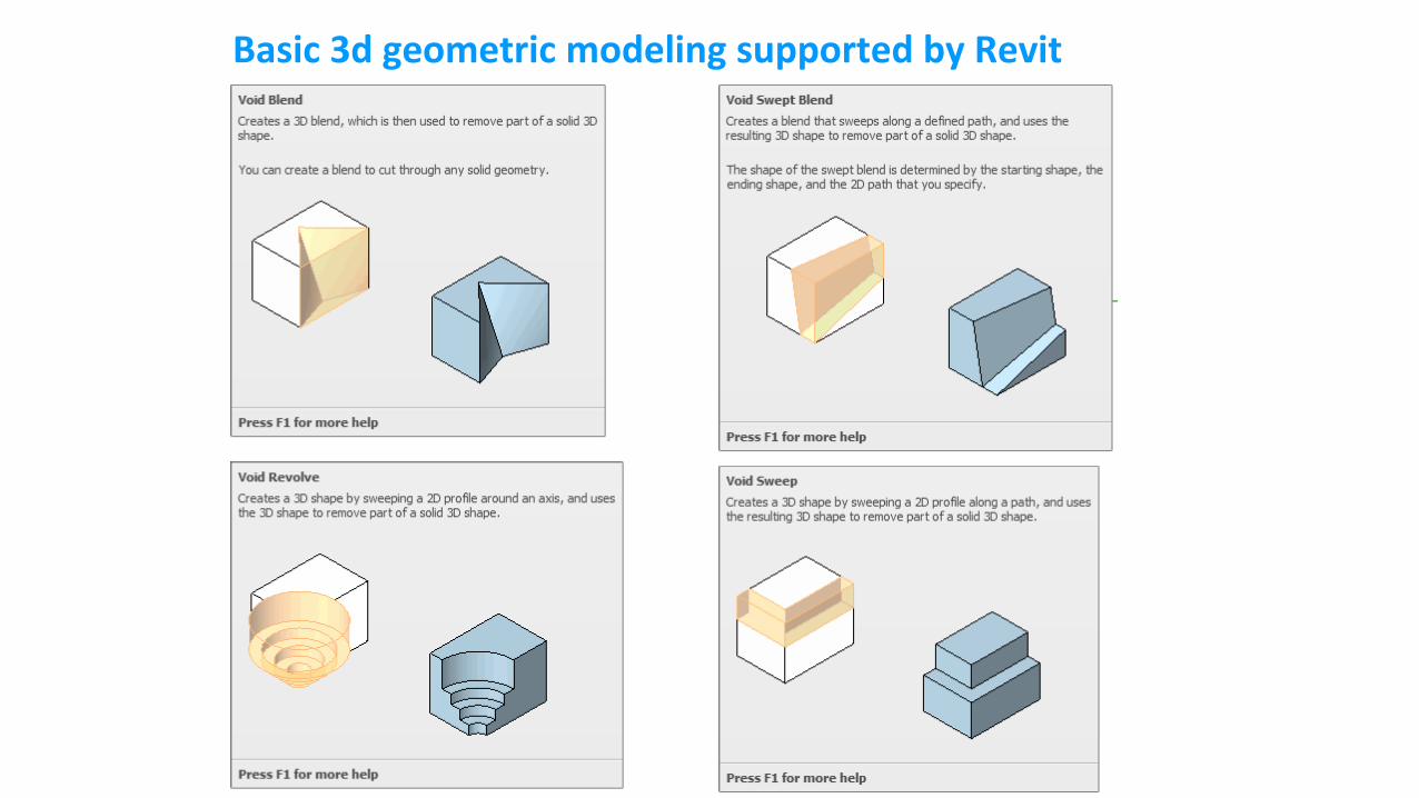
Basic 3d geometric modeling supported by Revit

Review: Parametric Modeling

Parametric & Feature-based Modeling
Features are defined to be parametric shapes associated with attributes
such as intrinsic geometric parameters (length, width, depth etc.), position and orientation, geometric
tolerances, material properties, and references to other features.
Features also provide access to related production processes and resource models. Thus, features
have a semantically higher level than primitive closed regular sets. Features are generally expected to
form a basis for linking CAD with downstream manufacturing applications, and also for organizing
databases for design data reuse.

Parametric Modeling
Parametric modeling uses parameters to define a model (dimensions, for example). Examples of
parameters are: dimensions used to create model features, material density, formulas to describe swept
features, imported data (that describe a reference surface, for example). The parameter may be
modified later, and the model will update to reflect the modification. Typically, there is a relationship
between parts, assemblies, and drawings. A part consists of multiple features, and an assembly
consists of multiple parts. Drawings can be made from either parts or assemblies.
Related to parameters, but slightly different are Constraints. Constraints are relationships between
entities that make up a particular shape. For a window, the sides might be defined as being parallel, and
of the same length. Parametric modeling is obvious and intuitive. But for the first three decades of CAD
this was not the case. Modification meant re-draw, or add a new cut or protrusion on top of old ones.
Dimensions on engineering drawings were created, instead of shown. Parametric modeling is very
powerful, but requires more skill in model creation. Parametric modeling also lends itself to data re-use.
Refer to Wikipedia
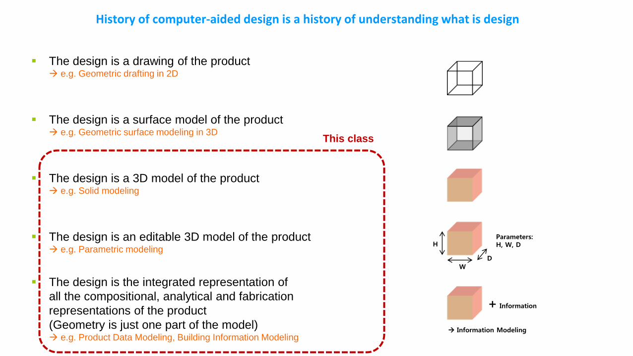
History of computer-aided design is a history of understanding what is design
The design is a drawing of the product e.g. Geometric drafting in 2D
The design is a surface model of the product e.g. Geometric surface modeling in 3D
The design is a 3D model of the product e.g. Solid modeling
The design is an editable 3D model of the product e.g. Parametric modeling
The design is the integrated representation of
all the compositional, analytical and fabrication
representations of the product
(Geometry is just one part of the model) e.g. Product Data Modeling, Building Information Modeling
H
W
D
Parameters:H, W, D
+ Information
Information Modeling
This class


Non-uniform Design of Buildings


Free-form 3d shapes
Parametric Modeling (Parametric Design)
Feature-based modeling (Section profile + Path = Sweeping, Blend
sweep…)

Non-uniform Design, Parametric Design, and BIM
Inevitable trend in recent AEC-FM industry


Case Study: Gansam Architects and Partners
신사동 페이토빌딩, 해군안보전시관, 프라자호텔 리모델링
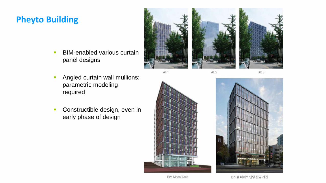
Pheyto Building
BIM-enabled various curtain
panel designs
Angled curtain wall mullions:
parametric modeling
required
Constructible design, even in
early phase of design

Republic of Korea Navy
2009.08 Design Competition model

Republic of Korea Navy: Design Process
Maya (obj/iges file)
Rhino (sat file)
Revit
Mass surface panel design by Revit:
- Parametric modeling
- Pre-fabricated exterior panels

Remodeling project:Plaza Hotel
Before
After
Under the construction
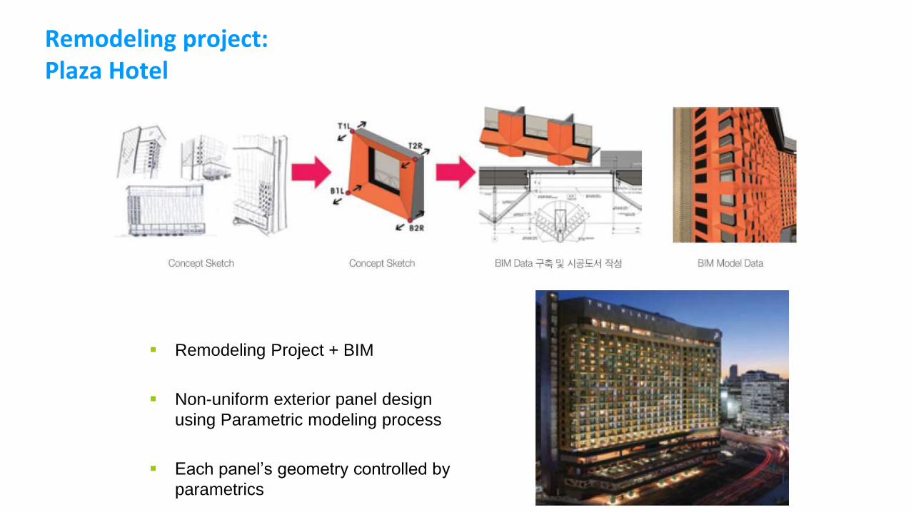
Remodeling project:Plaza Hotel
Remodeling Project + BIM
Non-uniform exterior panel design
using Parametric modeling process
Each panel’s geometry controlled by
parametrics

Remodeling project:Plaza Hotel


A (Free) Parametric Design Tool: Autodesk Vasari

Autodesk Vasari, free software as of 2014 (Search Google “Autodesk Vasari Project” and download)
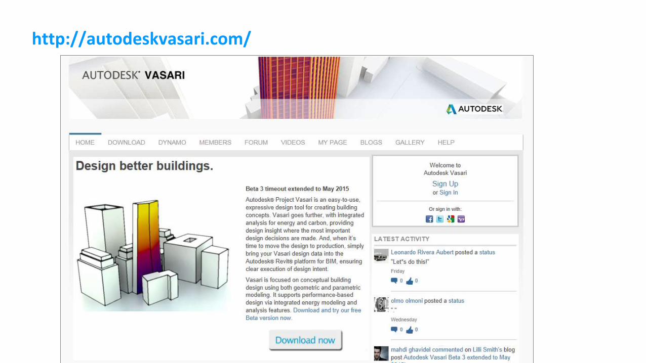
http://autodeskvasari.com/

Vasari User Interface (almost same to Revit)
Ribbon Interface
Dynamic Interface
Contextual interface which is based on helping meet the user needs

Mere example

Mass modeling

Parametric Design using Autodesk Vasari
- Curtain Panel Modeling
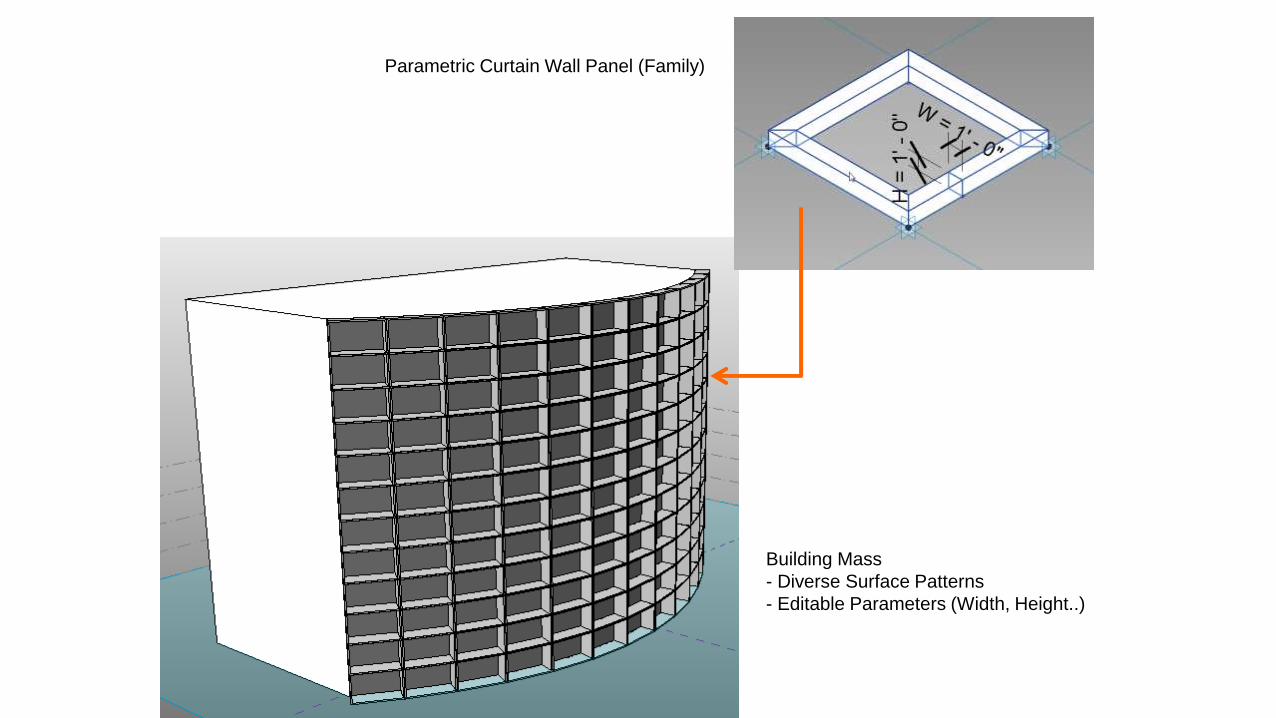
Parametric Curtain Wall Panel (Family)
Building Mass
- Diverse Surface Patterns
- Editable Parameters (Width, Height..)

Parametric Curtain Wall Panel (Family)
Building Surface
- Editable Surface Geometry
- Editable Curtain Panel Parameters


Curtain Wall Panel System

Curtain Wall Systems
Seoul City Hall, 2012
Non-uniform surface
Panelized curtain wall system

Design models vs. As built pictures (Seoul City Hall)
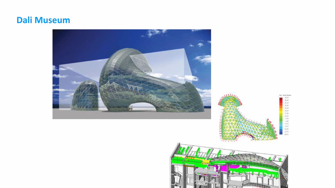
Dali Museum
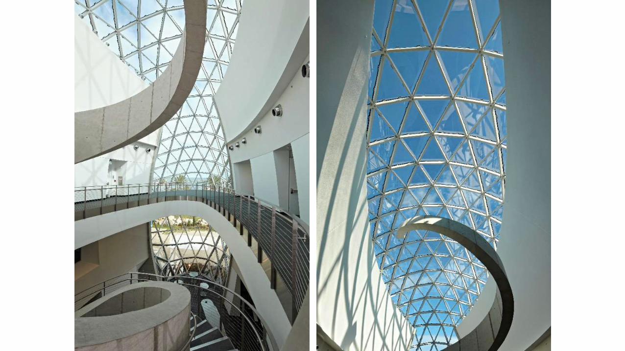

Curtain Wall Panel Design Example by 3ds Max
Architectural Organic, Non-uniform, Freeform
For updating design, always edit geometry: Vertex, Edge, Polygons, etc.
3ds Max does NOT know what are they – no parametric system. Just complex surfaces.
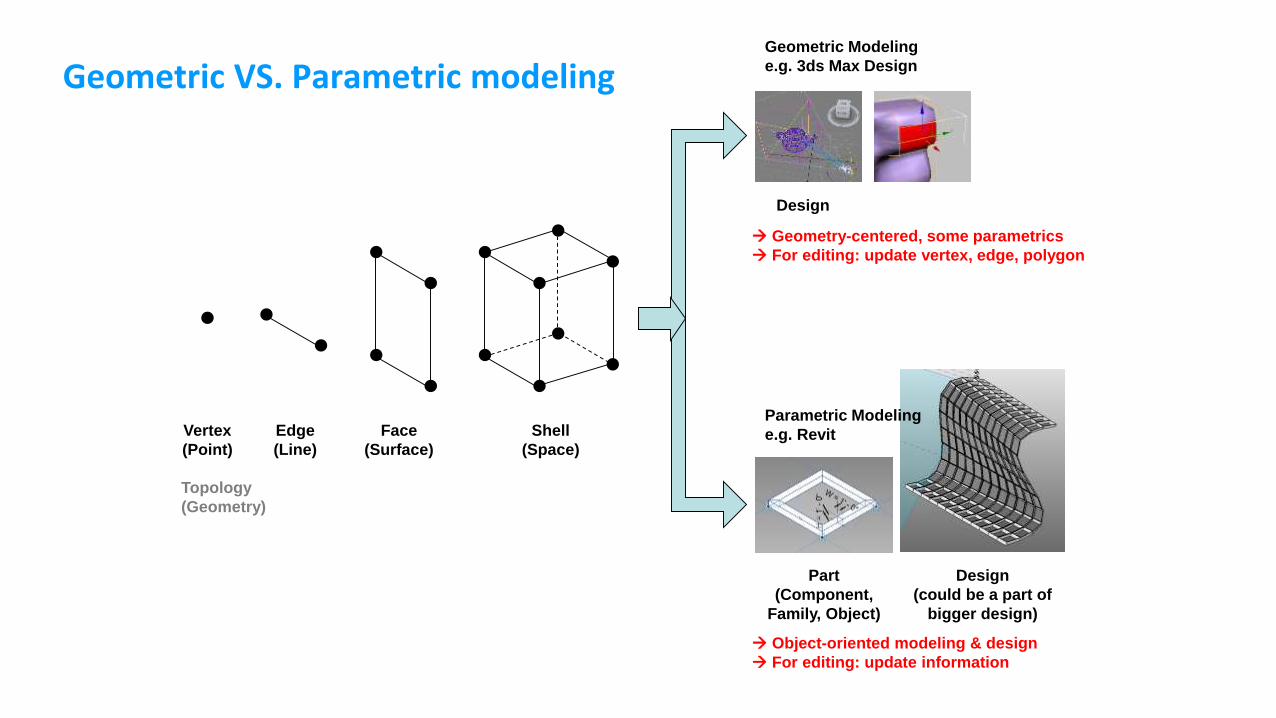
Geometric VS. Parametric modeling
Vertex
(Point)
Edge
(Line)
Face
(Surface)
Shell
(Space)
Geometric Modeling
e.g. 3ds Max Design
Design
Parametric Modeling
e.g. Revit
Part
(Component,
Family, Object)
Design
(could be a part of
bigger design)
Geometry-centered, some parametrics
For editing: update vertex, edge, polygon
Object-oriented modeling & design
For editing: update information
Topology
(Geometry)
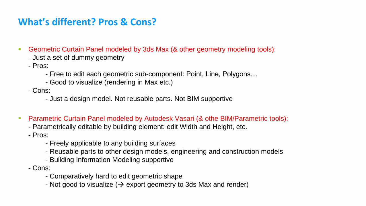
What’s different? Pros & Cons?
Geometric Curtain Panel modeled by 3ds Max (& other geometry modeling tools):
- Just a set of dummy geometry
- Pros:
- Free to edit each geometric sub-component: Point, Line, Polygons…
- Good to visualize (rendering in Max etc.)
- Cons:
- Just a design model. Not reusable parts. Not BIM supportive
Parametric Curtain Panel modeled by Autodesk Vasari (& othe BIM/Parametric tools):
- Parametrically editable by building element: edit Width and Height, etc.
- Pros:
- Freely applicable to any building surfaces
- Reusable parts to other design models, engineering and construction models
- Building Information Modeling supportive
- Cons:
- Comparatively hard to edit geometric shape
- Not good to visualize ( export geometry to 3ds Max and render)


Parametric Modeling Demo in Bentley Architecture
– Curtain Wall example 2

Example. Kawneer 2800 TRUSSWALL
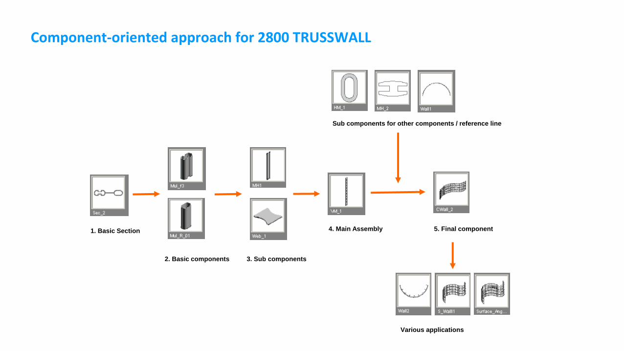
Component-oriented approach for 2800 TRUSSWALL
1. Basic Section
2. Basic components 3. Sub components
4. Main Assembly
Sub components for other components / reference line
5. Final component
Various applications

Constraints of basic mullion assembly
1. Height of Vertical Mullion Component Assembly
2. Same Height constraint for rear mullion
3. Array of Web
following Mullion Height
& their distance

Constraints of curved arc angle / distance
3. Mullion’s Horizontal Distance
ML_1 = 4’ 00” = ML_2 = ML_3 ……
2. Angle of Path line & point
A_1 = 350 = A_2 = A_3 ……
1. In case of A_1 = 360 degree
2. In case of ML_1 = 3’
Array distances were changed
simultaneously4. Array distance of Mullions
As same as ML_1
1. Angle of Mullion to path
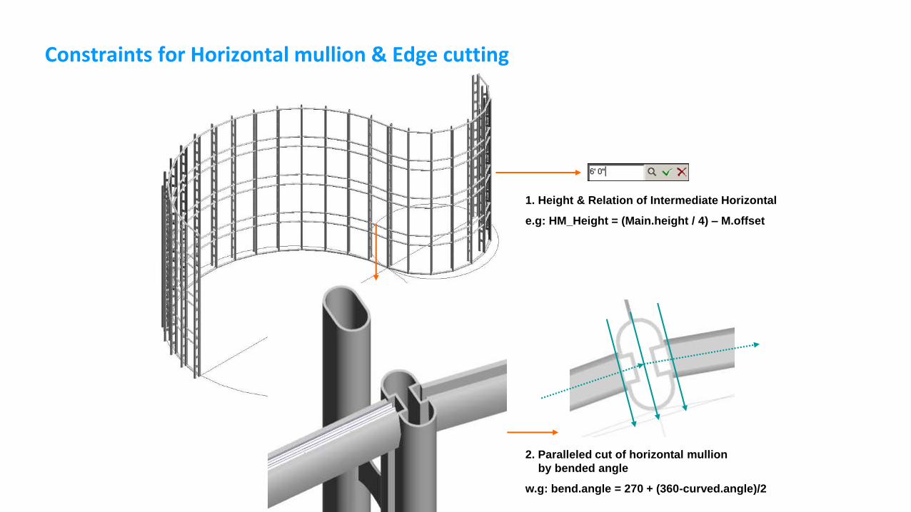
Constraints for Horizontal mullion & Edge cutting
1. Height & Relation of Intermediate Horizontal
e.g: HM_Height = (Main.height / 4) – M.offset
2. Paralleled cut of horizontal mullion
by bended angle
w.g: bend.angle = 270 + (360-curved.angle)/2

Center point of arc
C
A
B
Length:
a = b = c = d
Angle:
A = B
C = B/2 = A/2
Curtain wall path
a b
c
d
Horizontal Mullion

Center point of arc
C’
A’
Length:
a’ = b’ = d’
Angle:
A’ = B’
C’ = B’/2 = A’/2
a’b’
B’d’

Center point of arc
C”
A”
Length:
a” = b” = d”
Angle:
A” = B”
C” = B”/2 = A”/2
a”
b”
B”
d”

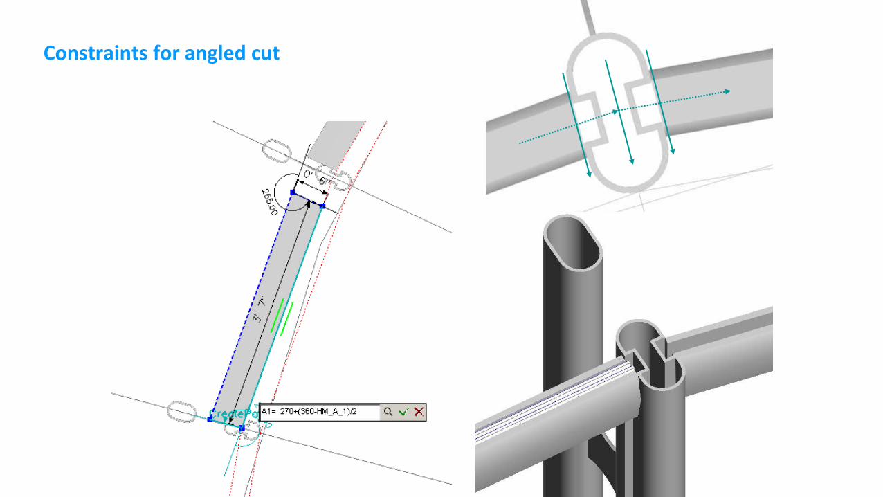
Constraints for angled cut
C
A
ab
B
d
A1
A2
L1
HM_A1
A2 = 540-A1
A1 = 270+(360-HM_A1)/2
Constraints for angled cut
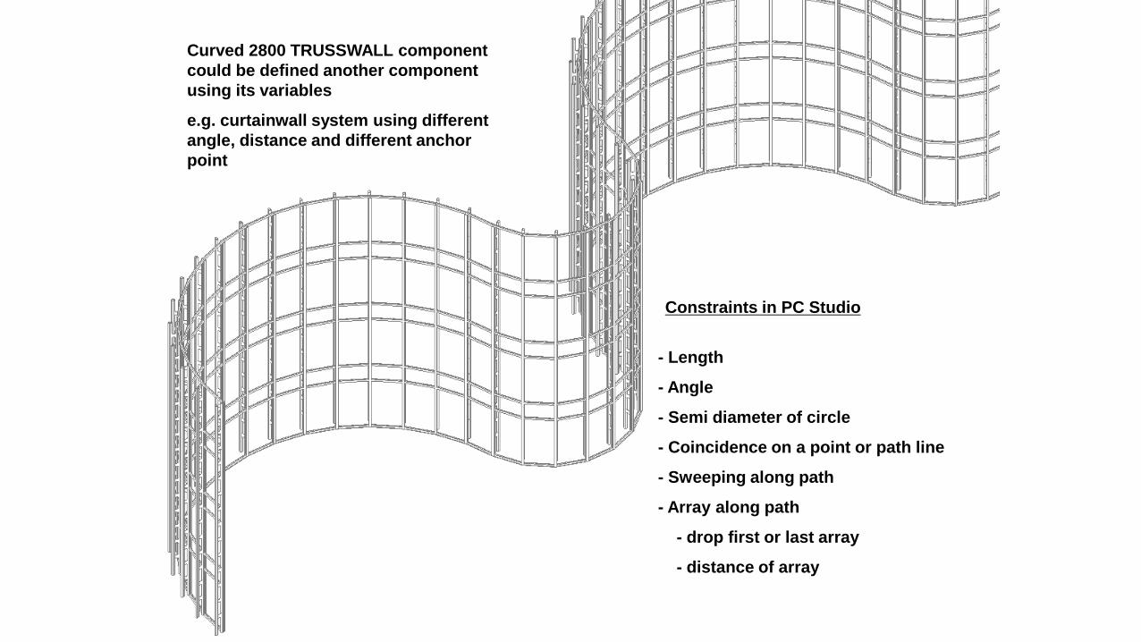
Curved 2800 TRUSSWALL component
could be defined another component
using its variables
e.g. curtainwall system using different
angle, distance and different anchor
point
- Length
- Angle
- Semi diameter of circle
- Coincidence on a point or path line
- Sweeping along path
- Array along path
- drop first or last array
- distance of array
Constraints in PC Studio
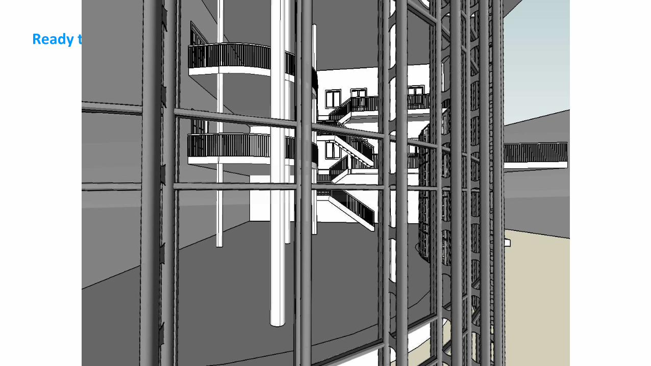
Ready to use in BA’s User defined object dialog box


BIM & Design Applications
We do design using Revit. What’s next?

법원청사건물 IFC모델
Space Program Review
Circulation & Security Rule Checking
Preliminary Energy Analysis
Preliminary Cost Estimation
- General spatial validation
- Compare to the program
- Area by Floor, Occupants, etc
- ANSI/BOMA based area calc
- Reusable Excel reporting
- PACES-based Cost DB
- GSA CH specific cost data
- Location-based cost data, etc
- Checking over 180 rules
- Evaluates thousands of paths
- Reporting problematic paths
- Reporting valid paths
- PDF reporting with images
조지아텍에서 연구, 개발한BIM기반 설계 품질 리뷰 및검증 도구GT-GSA Modules
- Creating energy zones
- Creating windows / shadings
- Analysis by rotated-direction
- Export to Energy Plus
- Reporting several results
다른 설계품질 검토항목에확대 적용 가능

Advanced spatial validation
Space Program Review
Using CAD: Typical area calculation (Net Area)
Using BIM:
- Net Area
- ANSI/BOMA area
- Usable area
- Rentable area
- Circulation factor
- ……

Circulation checking
All circulation between Space A and B: zero or many cases.
A circulation path has:
- Metric distance
- Spatial depth
- Number of turn
- Horizontal/vertical circulation
- Area of circulation spaces, number of windows, area of windows, height…


Lab Exercises

Next Class
Track 2: Theories in 3d graphics & tool
Design Visualization:
- Renderers: Vray & Mental Ray
Track 4: 3d Graphics Lab
SketchUP & 3dsMAX