03.2- uml overview
TRANSCRIPT
بسم هللا الرحمن الرحيم
Introduction to
Unified Modeling Language (UML)
Prepared By:
Eng.\ Tarig Ahmed Khalid, M.Sc., PMP, CEC, CBAP
1.1 Object Oriented Analysis (OOA):
a. Object Structure Analysis:
Concerned with object types and their associations.
b. Object Behavior Analysis:
Concerned with what happens to the objects over time.
1. Object Oriented Analysis & Design

1.2 Object Oriented Design (OOD):
a. Object Structure Design:
Concerned with classes and inheritance.
b. Object Behavior Design:
Concerned with the design of methods and messaging.

Overview:
The Unified Modeling Language (UML) is a language
for specifying, visualizing, constructing, and
documenting the artifacts of software systems, as well
as for business modeling and other non-software
systems.
The UML represents a collection of the best
engineering practices that have proven successful in the
modeling of large and complex systems.
2. Unified Modeling Language
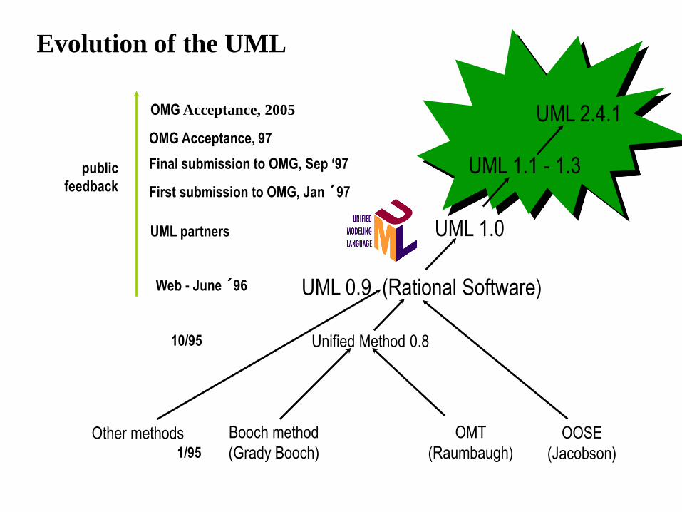
Evolution of the UML
Booch method
(Grady Booch)
OMT
(Raumbaugh)
Unified Method 0.8 10/95
OOSE
(Jacobson)
Other methods
UML 0.9 (Rational Software) Web - June ´96
public
feedback
Final submission to OMG, Sep ‘97
First submission to OMG, Jan ´97
UML 1.1 - 1.3
OMG Acceptance, 97
UML 2.4.1
UML 1.0 UML partners
1/95
OMG Acceptance, 2005
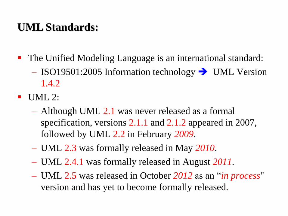
UML Standards:
The Unified Modeling Language is an international standard:
– ISO19501:2005 Information technology UML Version
1.4.2
UML 2:
– Although UML 2.1 was never released as a formal
specification, versions 2.1.1 and 2.1.2 appeared in 2007,
followed by UML 2.2 in February 2009.
– UML 2.3 was formally released in May 2010.
– UML 2.4.1 was formally released in August 2011.
– UML 2.5 was released in October 2012 as an “in process"
version and has yet to become formally released.
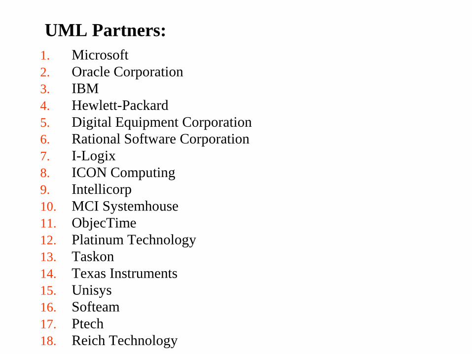
UML Partners:
1. Microsoft
2. Oracle Corporation
3. IBM
4. Hewlett-Packard
5. Digital Equipment Corporation
6. Rational Software Corporation
7. I-Logix
8. ICON Computing
9. Intellicorp
10. MCI Systemhouse
11. ObjecTime
12. Platinum Technology
13. Taskon
14. Texas Instruments
15. Unisys
16. Softeam
17. Ptech
18. Reich Technology

3. UML Diagrams
A diagram is a view into a model:
– Presented from the aspect of a particular stakeholder
– Provides a partial representation of the system
– Is semantically consistent with other views
In the UML, there are 9+ standard diagrams:
– Static views:
1. Structural Diagrams
2. Implementation
– Dynamic views:
1. Behavioral
2. Interaction
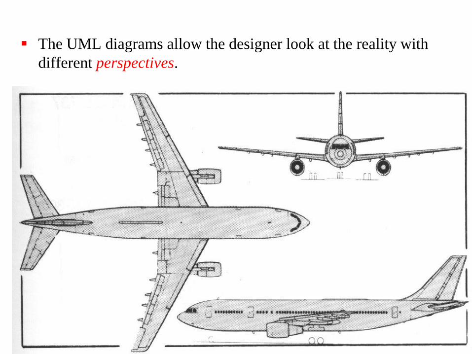
The UML diagrams allow the designer look at the reality with
different perspectives.
Features of the UML:
In terms of the views of a model, the UML
defines the following graphical diagrams:
1. Structure Diagrams
2. Behavior Diagrams
3. Interaction Diagrams
4. Implementation Diagrams

3.1 Structural Diagrams
1. Use Case Diagram
2. Class Diagram
3. Object Diagram
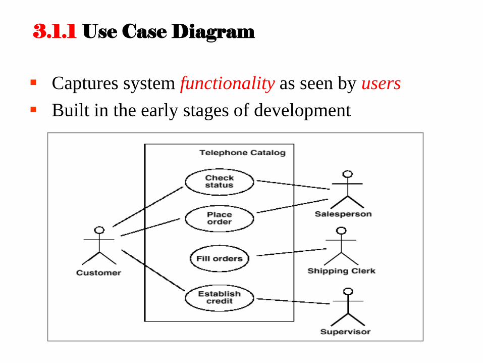
3.1.1 Use Case Diagram
Captures system functionality as seen by users
Built in the early stages of development

3.1.2 Class Diagram
Captures the vocabulary of a system
Built and refined throughout development
Purpose:
– Name and model concepts in the system
– Specify collaborations
Developed by analysts, designers, and implementers

Captures the vocabulary of a system
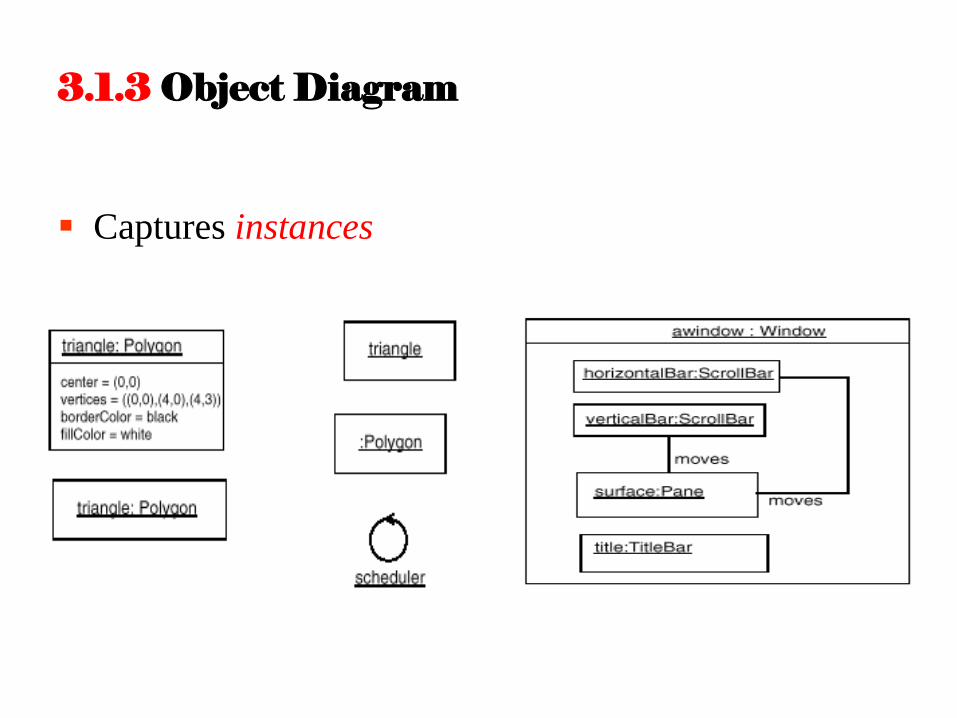
3.1.3 Object Diagram
Captures instances

Shows instances
Built during analysis and design
Purpose:
– Illustrate data/object structures
– Specify snapshots
Developed by analysts, designers, and implementers
1. State-chart Diagram
2. Activity Diagram
3.2 Behavior Diagrams
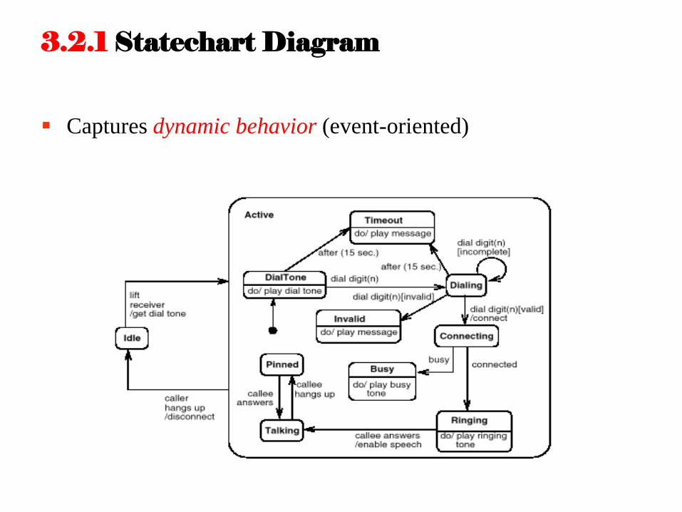
3.2.1 Statechart Diagram
Captures dynamic behavior (event-oriented)
Captures dynamic behavior (event-oriented)
Purpose:
– Model object lifecycle
– Model reactive objects (user interfaces, devices, etc.)
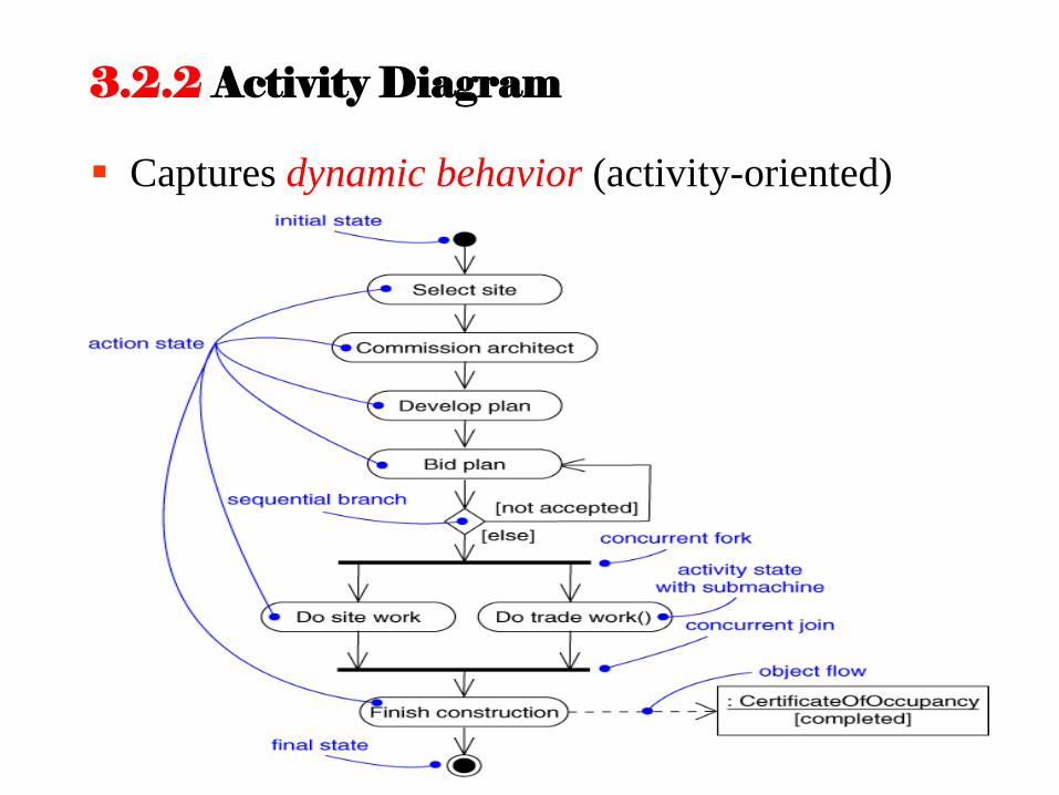
3.2.2 Activity Diagram
Captures dynamic behavior (activity-oriented)

Captures dynamic behavior (activity- oriented)
Purpose:
– Model business workflows
– Model operations
1. Sequence Diagram
2. Collaboration Diagram
3.3 Interaction Diagrams
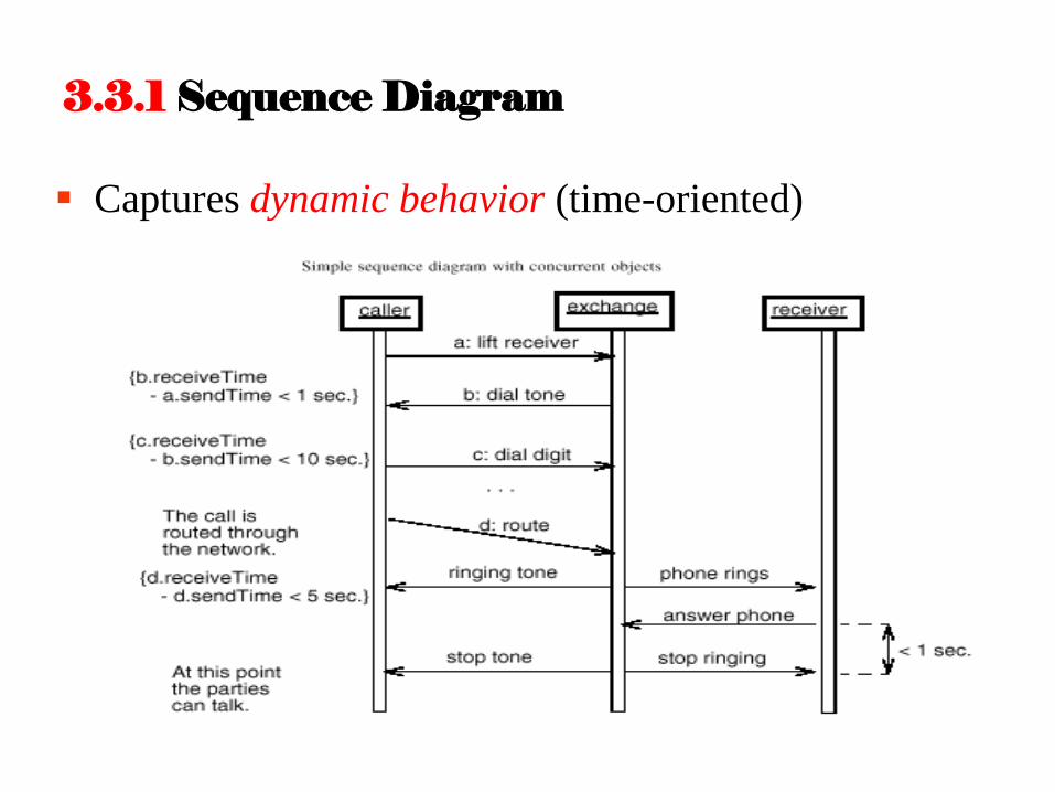
3.3.1 Sequence Diagram
Captures dynamic behavior (time-oriented)
Captures dynamic behavior (time-oriented)
Purpose:
– Model flow of control
– Illustrate typical scenarios

3.3.2 Collaboration Diagram
Captures dynamic behavior (message-oriented)
Captures dynamic behavior (message-oriented)
Purpose
– Model flow of control
– Illustrate coordination of object structure and control
1. Component Diagram
2. Deployment Diagram
3.4 Implementation Diagrams
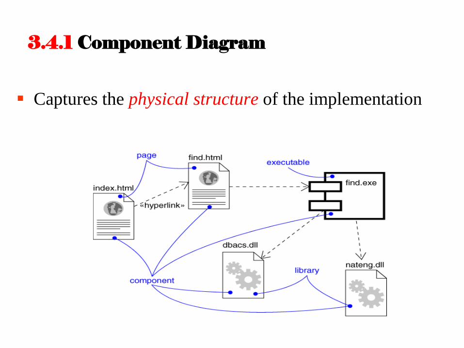
3.4.1 Component Diagram
Captures the physical structure of the implementation
Captures the physical structure of the implementation
Built as part of architectural specification
Purpose:
– Organize source code
– Construct an executable release
– Specify a physical database
Developed by architects and programmers
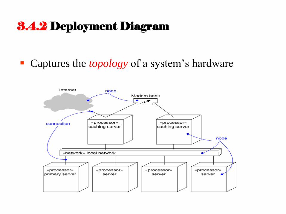
3.4.2 Deployment Diagram
Captures the topology of a system’s hardware

Captures the topology of a system’s hardware
Built as part of architectural specification
Purpose:
– Specify the distribution of components
– Identify performance bottlenecks
Developed by architects, networking engineers, and system engineers
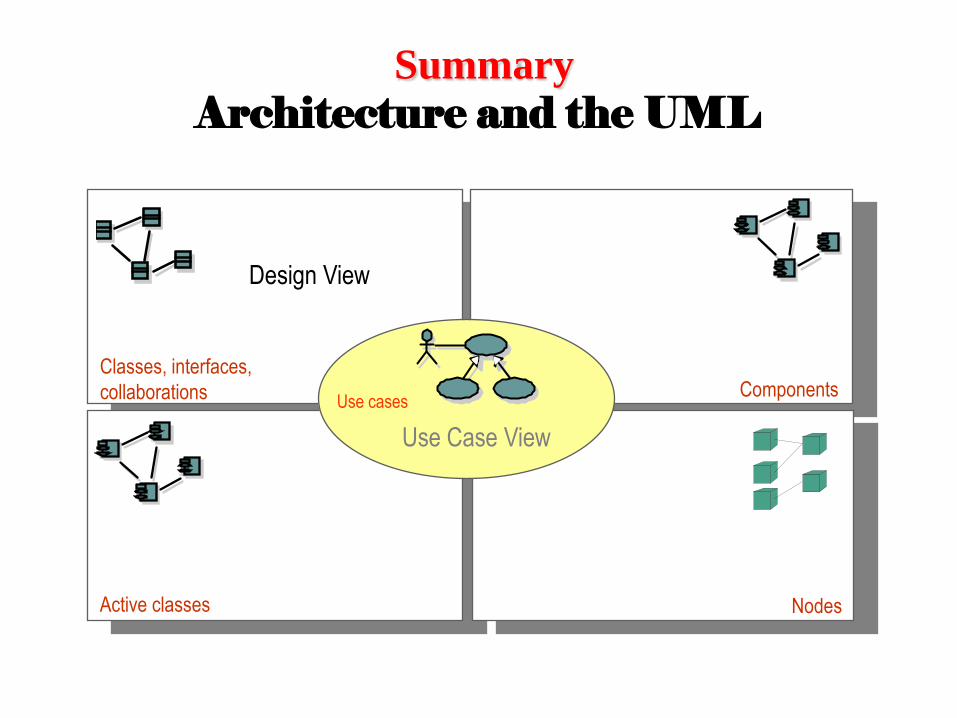
Summary
Architecture and the UML
Design View Implementation View
Process View
Components Classes, interfaces,
collaborations
Active classes
Deployment View
Nodes
Use Case View
Use cases
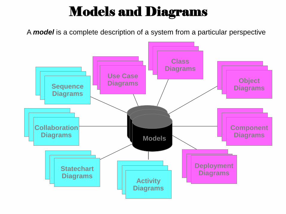
Models and Diagrams
Use Case Diagrams Use Case
Diagrams Use Case Diagrams
Scenario Diagrams Scenario
Diagrams Collaboration Diagrams
State Diagrams State
Diagrams Component Diagrams
Component Diagrams Component
Diagrams Deployment
Diagrams
State Diagrams State
Diagrams Object Diagrams
Scenario Diagrams Scenario
Diagrams Statechart Diagrams
Use Case Diagrams Use Case
Diagrams Sequence Diagrams
State Diagrams State
Diagrams Class Diagrams
Activity Diagrams
A model is a complete description of a system from a particular perspective
Models
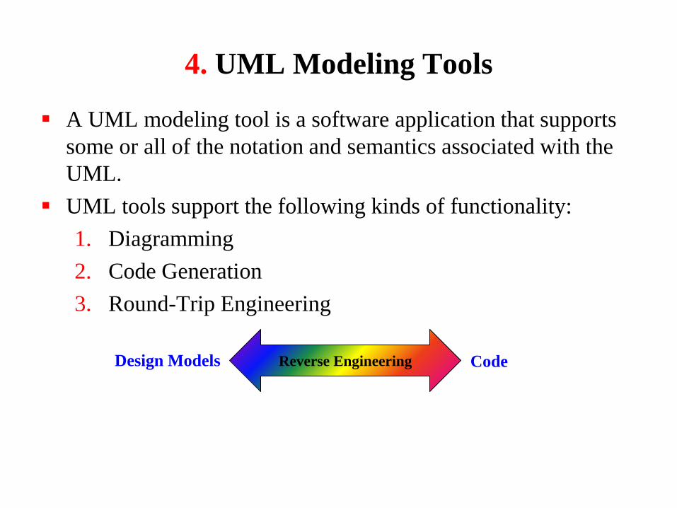
4. UML Modeling Tools
A UML modeling tool is a software application that supports
some or all of the notation and semantics associated with the
UML.
UML tools support the following kinds of functionality:
1. Diagramming
2. Code Generation
3. Round-Trip Engineering
Code Design Models Reverse Engineering
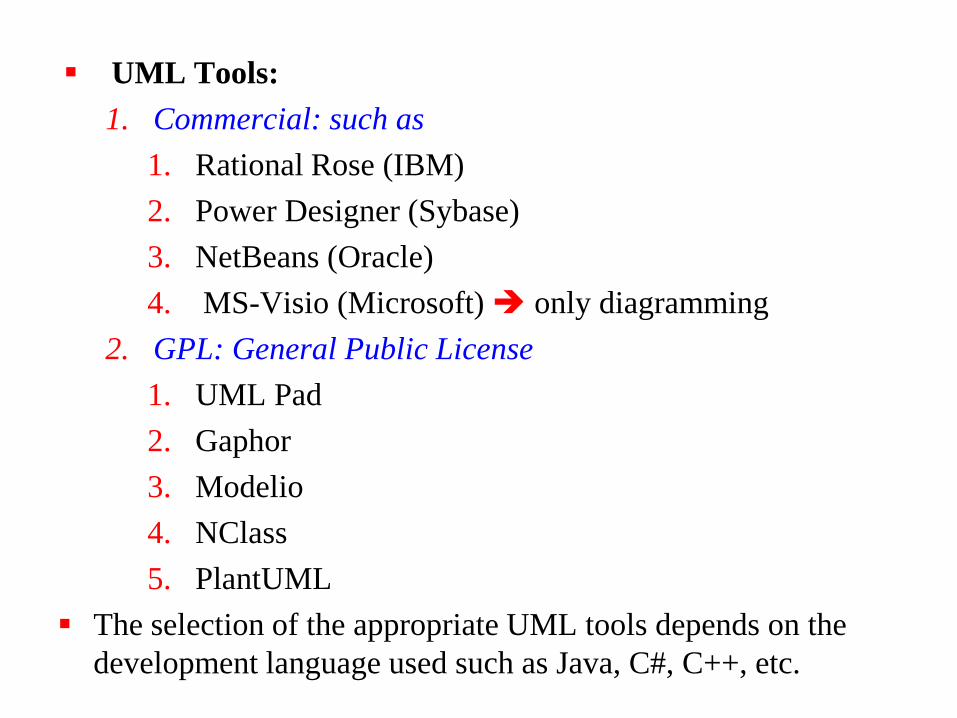
UML Tools:
1. Commercial: such as
1. Rational Rose (IBM)
2. Power Designer (Sybase)
3. NetBeans (Oracle)
4. MS-Visio (Microsoft) only diagramming
2. GPL: General Public License
1. UML Pad
2. Gaphor
3. Modelio
4. NClass
5. PlantUML
The selection of the appropriate UML tools depends on the
development language used such as Java, C#, C++, etc.