03 radiance primer
TRANSCRIPT
Radiance Primer
Giulio Antonutto & Andrew McNeil
Table of Contents
Radiance Overview 1
Radiance Flowchart 1
Scene Input 2
Geometry 2
Materials 5
Combining Materials and Geometry 8
oconv 9
Simulation 10
rpict 10
rtrace 16
rvu 17
ximage 18
Post-Processing 19
Radiance Primer i
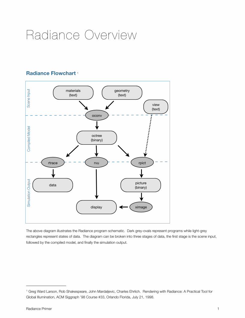
Radiance Overview
Radiance Flowchart 1
The above diagram illustrates the Radiance program schematic. Dark grey-ovals represent programs while light-grey
rectangles represent states of data. The diagram can be broken into three stages of data, the first stage is the scene input,
followed by the compiled model, and finally the simulation output.
Radiance Primer 1
1 Greg Ward Larson, Rob Shakespeare, John Mardaljevic, Charles Ehrlich. Rendering with Radiance: A Practical Tool for
Global Illumination, ACM Siggraph ’98 Course #33, Orlando Florida, July 21, 1998.
materials(text)
geometry(text)
octree(binary)
picture(binary)
display
data
oconv
rtrace rvu rpict
ximage
view(text)
Sce
ne In
put
Com
pile
d M
odel
Sim
ulat
ion
Out
put
Scene Input
GeometryIn most cases you will generate your geometry in a CAD program and then translate it to Radiance format. However it is
important to understand how surface geometry is specified in the Radiance format to be able to use Radiance to its fullest
extent.
Radiance scene geometry is specified in the following format:
modifier type namem a1 a2 a3 ... am0n a1 a2 a3 ... an
For a geometry primitive the modifier is the name of the material that is applied to the surface. Type is the type of surface
(polygon, sphere, cone, etc.). Name is an identifier that is given to the surface (this can be arbitrary).
The next three lines contain arguments that define the surface. This is where coordinates and sizes are entered according to
the surface template. Each line will begin with an integer that defines the number of arguments on the line. Most arguments
are placed on the third line of the geometry definition. The second line is always ‘0’ with no arguments.
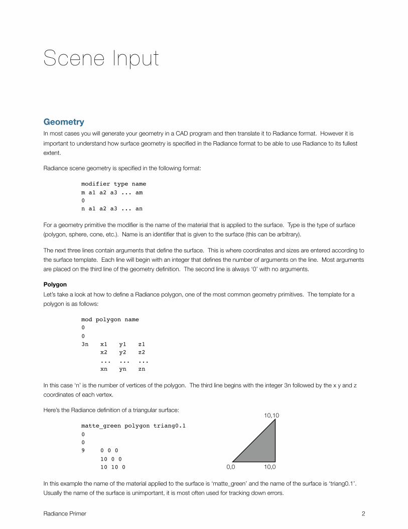
Polygon
Let’s take a look at how to define a Radiance polygon, one of the most common geometry primitives. The template for a
polygon is as follows:
mod polygon name003n x1 y1 z1 x2 y2 z2 ... ... ... xn yn zn
In this case ‘n’ is the number of vertices of the polygon. The third line begins with the integer 3n followed by the x y and z
coordinates of each vertex.
Here’s the Radiance definition of a triangular surface:
matte_green polygon triang0.1009 0 0 0 10 0 0 10 10 0
In this example the name of the material applied to the surface is ‘matte_green’ and the name of the surface is ‘triang0.1’.
Usually the name of the surface is unimportant, it is most often used for tracking down errors.
Radiance Primer 2
0,0 10,0
10,10
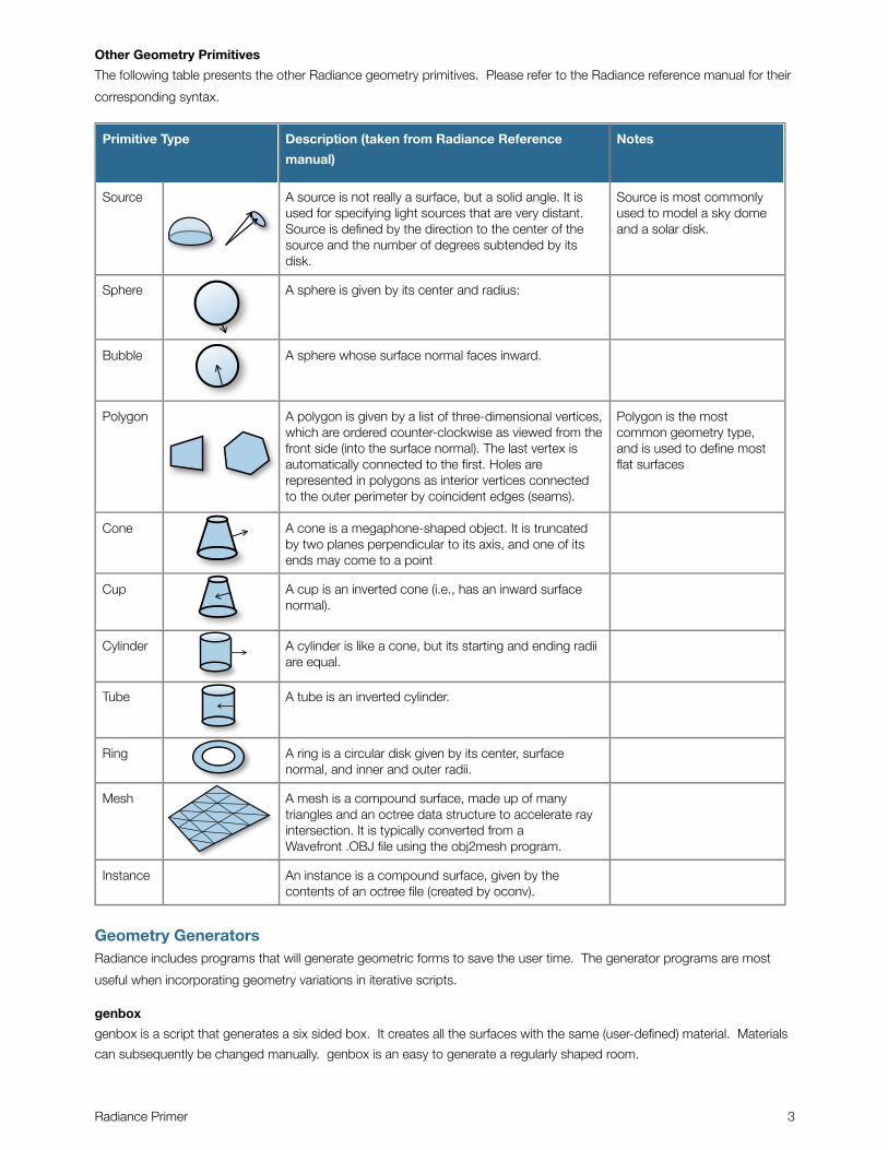
Other Geometry Primitives
The following table presents the other Radiance geometry primitives. Please refer to the Radiance reference manual for their
corresponding syntax.
Primitive Type Description (taken from Radiance Reference
manual)
Notes
Source A source is not really a surface, but a solid angle. It is used for specifying light sources that are very distant. Source is defined by the direction to the center of the source and the number of degrees subtended by its disk.
Source is most commonly used to model a sky dome and a solar disk.
Sphere A sphere is given by its center and radius:
Bubble A sphere whose surface normal faces inward.
Polygon A polygon is given by a list of three-dimensional vertices, which are ordered counter-clockwise as viewed from the front side (into the surface normal). The last vertex is automatically connected to the first. Holes are represented in polygons as interior vertices connected to the outer perimeter by coincident edges (seams).
Polygon is the most common geometry type, and is used to define most flat surfaces
Cone A cone is a megaphone-shaped object. It is truncated by two planes perpendicular to its axis, and one of its ends may come to a point
Cup A cup is an inverted cone (i.e., has an inward surface normal).
Cylinder A cylinder is like a cone, but its starting and ending radii are equal.
Tube A tube is an inverted cylinder.
Ring A ring is a circular disk given by its center, surface normal, and inner and outer radii.
Mesh A mesh is a compound surface, made up of many triangles and an octree data structure to accelerate ray intersection. It is typically converted from a Wavefront .OBJ file using the obj2mesh program.
Instance An instance is a compound surface, given by the contents of an octree file (created by oconv).
Geometry GeneratorsRadiance includes programs that will generate geometric forms to save the user time. The generator programs are most
useful when incorporating geometry variations in iterative scripts.
genbox
genbox is a script that generates a six sided box. It creates all the surfaces with the same (user-defined) material. Materials
can subsequently be changed manually. genbox is an easy to generate a regularly shaped room.
Radiance Primer 3
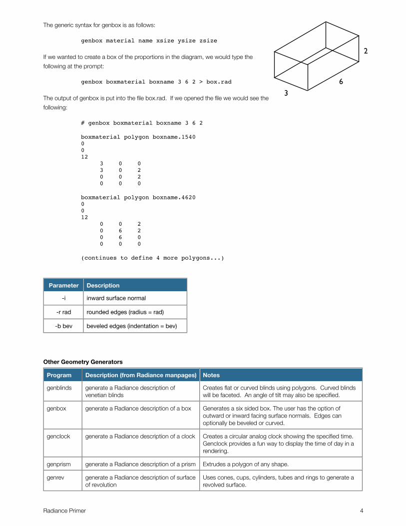
The generic syntax for genbox is as follows:
genbox material name xsize ysize zsize
If we wanted to create a box of the proportions in the diagram, we would type the
following at the prompt:
genbox boxmaterial boxname 3 6 2 > box.rad
The output of genbox is put into the file box.rad. If we opened the file we would see the
following:
# genbox boxmaterial boxname 3 6 2
boxmaterial polygon boxname.15400012 3 0 0 3 0 2 0 0 2 0 0 0
boxmaterial polygon boxname.46200012 0 0 2 0 6 2 0 6 0 0 0 0
(continues to define 4 more polygons...)
Parameter Description
-i inward surface normal
-r rad rounded edges (radius = rad)
-b bev beveled edges (indentation = bev)
Other Geometry Generators
Program Description (from Radiance manpages) Notes
genblinds generate a Radiance description of venetian blinds
Creates flat or curved blinds using polygons. Curved blinds will be faceted. An angle of tilt may also be specified.
genbox generate a Radiance description of a box Generates a six sided box. The user has the option of outward or inward facing surface normals. Edges can optionally be beveled or curved.
genclock generate a Radiance description of a clock Creates a circular analog clock showing the specified time. Genclock provides a fun way to display the time of day in a rendering.
genprism generate a Radiance description of a prism Extrudes a polygon of any shape.
genrev generate a Radiance description of surface of revolution
Uses cones, cups, cylinders, tubes and rings to generate a revolved surface.
Radiance Primer 4
6
2
3
Program Description (from Radiance manpages) Notes
gensky generate a Radiance description of the sky The most frequently used of all the gen programs, gensky will produce a sky with a CIE luminance distribution.
gensurf generate a Radiance or Wavefront description of a curved surface
creates a triangulated surface based on parametric equations.
genworm generate a Radiance description of a functional worm
uses cones cylinders and spheres to create a worm based on parametric equation input.
MaterialsUnlike geometry, which will typically be produced in CAD and translated to Radiance, materials are typically specified by
hand in Radiance.
Materials are specified in the following format:
modifier type namem a1 a2 a3 ... am0n a1 a2 a3 ... an
Primitive is the type of material that is being defined. Primitive types include plastic, metal, light, glass, trans etc... We will
get into more detail of the material types later.
Modifier is the name of a previously defined element that modifies this material. In most cases ‘void’ is used in place of a
modifier for material definitions. However if a pattern or texture is applied to a material, the name of the pattern or texture will
be the modifier.
‘name’ is a name assigned to the material. The material name will be used later as the modifier for a geometry primitive.
The next three lines contain arguments that define the materials. Each line begins with and integer which defines the
number of arguments on the line. Most arguments are placed on the third line of the material definition.
Plastic
We’ll start by looking at the most commonly used material, plastic. Plastic is a material with highlights that are unaffected by
the color of the material. Imagine a red plastic ball under a spotlight, the specular reflection of the spotlight will be the color
of the light. Plastic is specified as follows:
mod plastic name005 red green blue specularity roughness
To specify a matte green surface, one might use the following parameters:
void plastic matte_green005 .2 .6 .25 0 0
The material matte green has the RGB reflectance 0.2, 0.6, 0.25, has a specular reflectance of zero and a roughness of 0.
Other Material Primitives
The following table contains commonly used Radiance materials. For a complete list of materials, and material specifications
please refer to the radiance reference manual.
Radiance Primer 5
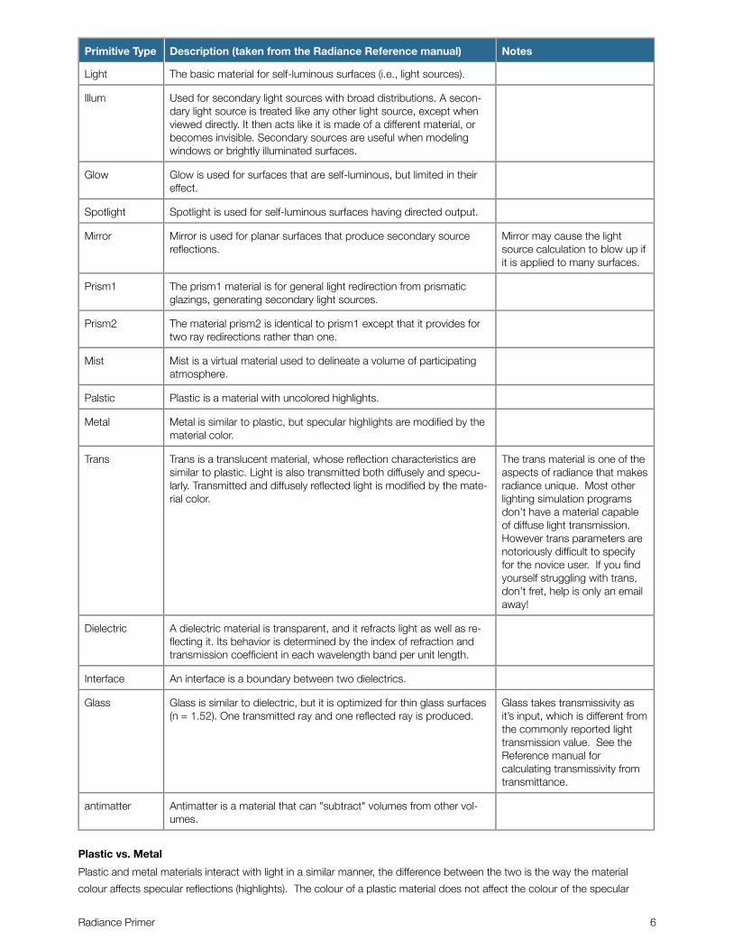
Primitive Type Description (taken from the Radiance Reference manual) Notes
Light The basic material for self-luminous surfaces (i.e., light sources).
Illum Used for secondary light sources with broad distributions. A secon-dary light source is treated like any other light source, except when viewed directly. It then acts like it is made of a different material, or becomes invisible. Secondary sources are useful when modeling windows or brightly illuminated surfaces.
Glow Glow is used for surfaces that are self-luminous, but limited in their effect.
Spotlight Spotlight is used for self-luminous surfaces having directed output.
Mirror Mirror is used for planar surfaces that produce secondary source reflections.
Mirror may cause the light source calculation to blow up if it is applied to many surfaces.
Prism1 The prism1 material is for general light redirection from prismatic glazings, generating secondary light sources.
Prism2 The material prism2 is identical to prism1 except that it provides for two ray redirections rather than one.
Mist Mist is a virtual material used to delineate a volume of participating atmosphere.
Palstic Plastic is a material with uncolored highlights.
Metal Metal is similar to plastic, but specular highlights are modified by the material color.
Trans Trans is a translucent material, whose reflection characteristics are similar to plastic. Light is also transmitted both diffusely and specu-larly. Transmitted and diffusely reflected light is modified by the mate-rial color.
The trans material is one of the aspects of radiance that makes radiance unique. Most other lighting simulation programs don’t have a material capable of diffuse light transmission. However trans parameters are notoriously difficult to specify for the novice user. If you find yourself struggling with trans, don’t fret, help is only an email away!
Dielectric A dielectric material is transparent, and it refracts light as well as re-flecting it. Its behavior is determined by the index of refraction and transmission coefficient in each wavelength band per unit length.
Interface An interface is a boundary between two dielectrics.
Glass Glass is similar to dielectric, but it is optimized for thin glass surfaces (n = 1.52). One transmitted ray and one reflected ray is produced.
Glass takes transmissivity as it’s input, which is different from the commonly reported light transmission value. See the Reference manual for calculating transmissivity from transmittance.
antimatter Antimatter is a material that can "subtract" volumes from other vol-umes.
Plastic vs. Metal
Plastic and metal materials interact with light in a similar manner, the difference between the two is the way the material
colour affects specular reflections (highlights). The colour of a plastic material does not affect the colour of the specular
Radiance Primer 6
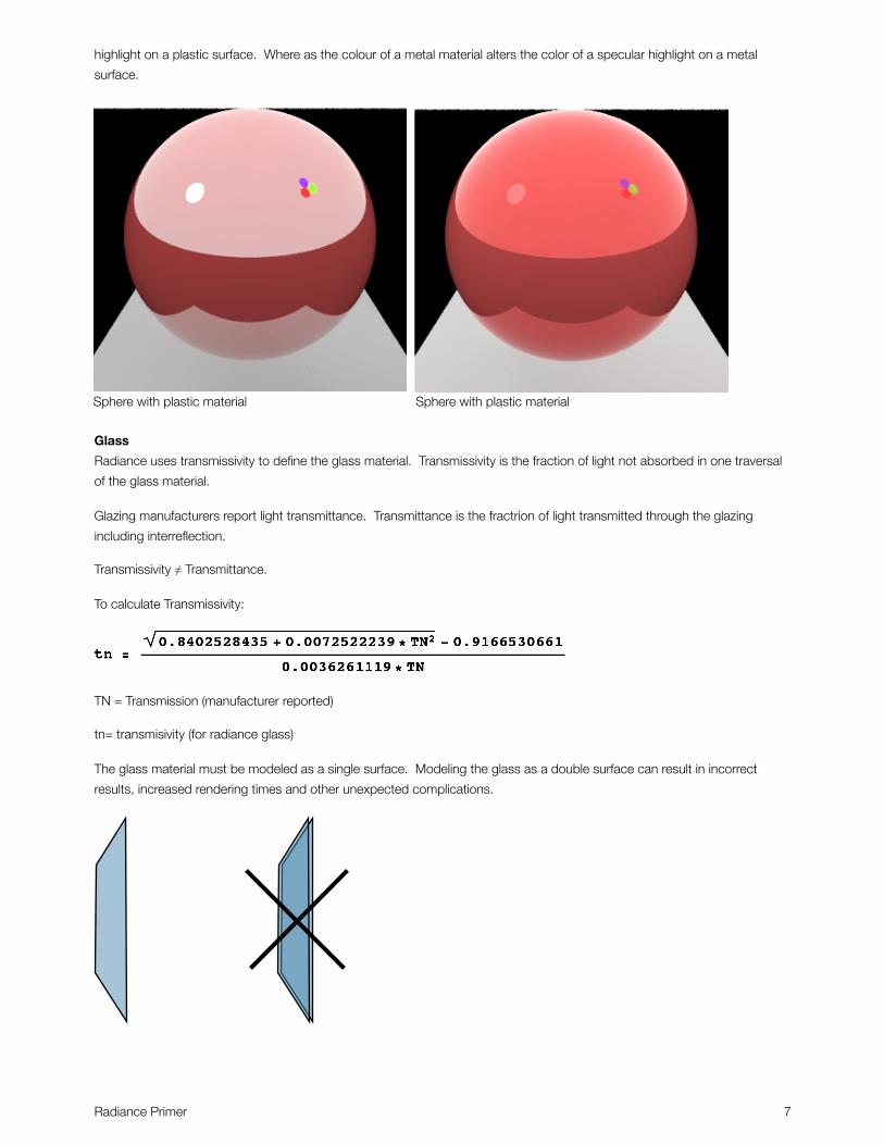
highlight on a plastic surface. Where as the colour of a metal material alters the color of a specular highlight on a metal
surface.
Sphere with plastic material Sphere with plastic material
Glass
Radiance uses transmissivity to define the glass material. Transmissivity is the fraction of light not absorbed in one traversal
of the glass material.
Glazing manufacturers report light transmittance. Transmittance is the fractrion of light transmitted through the glazing
including interreflection.
Transmissivity ≠ Transmittance.
To calculate Transmissivity:
TN = Transmission (manufacturer reported)
tn= transmisivity (for radiance glass)
The glass material must be modeled as a single surface. Modeling the glass as a double surface can result in incorrect
results, increased rendering times and other unexpected complications.
Radiance Primer 7
Combining Materials and GeometryNow let’s look at combining the material ‘matte_green’ with the triangle ‘triang0.1’. Material definitions must always precede
the objects they modify. So we put the material first, followed by the geometry.
void plastic matte_green005 .2 .6 .25 0 0
matte_green polygon triang0.1009 0 0 0 10 0 0 10 10 0
See how the material name becomes the of the geometry primitive? The modifier for the definition matte_green is void,
however if a texture or pattern were to be applied to the plastic, the modifier would become the name of the texture or
pattern.
If the above were put into a file it would be ready to be compiled into a binary octree using oconv.
objviewTo display geometry before we are ready for a simulation we can use objview. objview compiles the geometry and materials
along with some light sources into a temporary octree file and starts an rvu window to render the scene. objview does all
this without user input, so we don’t need to know anything about oconv or rvu however we will cover them in more detail
later.
The generic syntax for objview is as follows:
objview matfile.rad object1.rad object2.rad...
Where matfile.rad contains the material definitions and object.rad contains objects. We can mix the materials and objects
into a single file as long as the material definition precedes the geometry that uses it.
For example if we put the following into a file ‘bluewall.rad’
void plastic matte_blue005 .4 .45 .7 0 0
matte_blue polygon wall_10012 0 0 0 2 14 0 2 14 9 0 0 9
We could then type:
objview bluewall.rad
And a render window would pop up (you must have an X11 window server running for this to work).
Radiance Primer 8
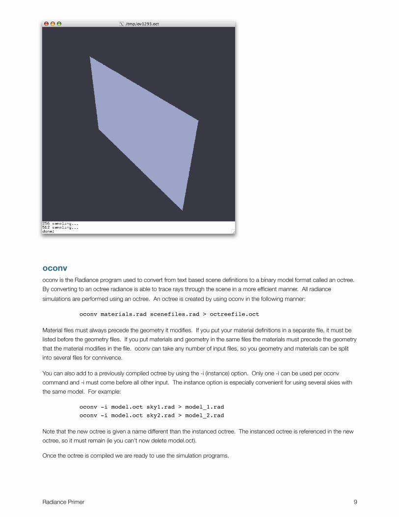
oconvoconv is the Radiance program used to convert from text based scene definitions to a binary model format called an octree.
By converting to an octree radiance is able to trace rays through the scene in a more efficient manner. All radiance
simulations are performed using an octree. An octree is created by using oconv in the following manner:
oconv materials.rad scenefiles.rad > octreefile.oct
Material files must always precede the geometry it modifies. If you put your material definitions in a separate file, it must be
listed before the geometry files. If you put materials and geometry in the same files the materials must precede the geometry
that the material modifies in the file. oconv can take any number of input files, so you geometry and materials can be split
into several files for connivence.
You can also add to a previously complied octree by using the -i (instance) option. Only one -i can be used per oconv
command and -i must come before all other input. The instance option is especially convenient for using several skies with
the same model. For example:
oconv -i model.oct sky1.rad > model_1.radoconv -i model.oct sky2.rad > model_2.rad
Note that the new octree is given a name different than the instanced octree. The instanced octree is referenced in the new
octree, so it must remain (ie you can’t now delete model.oct).
Once the octree is compiled we are ready to use the simulation programs.
Radiance Primer 9
Simulation
rpictThe program rpict is used to generate renderings. The program is invoked as follows:
rpict [options] model.oct > image.pic
Options for rpict can be broken into four categories:
• View Options
• Ambient Simulation Parameters
• Direct Simulation Parameters
• Other options
Ambient CalculationThe ambient calculation is used to describe the calculation of inter reflected light. For an explanation of how the ambient
calculation works, see the book Rendering with Radiance.
Ambient calculation parameters are an important part of the radiance programs. They ambient calculation is what takes a
majority of the time in a radiance simulation, the ambient parameters allow the user to adjust the accuracy and duration of a
radiance simulation. Setting the ambient parameters is not straight forward. Some parameters might increase time
drastically while only increasing accuracy slightly and vice versa. The “right” parameters vary depending on the model
characteristics. Even an experienced radiance user may find it difficult to choose the optimal ambient parameters for his/her
simulation.
The ambient parameters are generally the same for all the radiance simulation programs (rtrace, rpict and rvu). The
following table contains the most commonly used of these parameters.
Ambient options
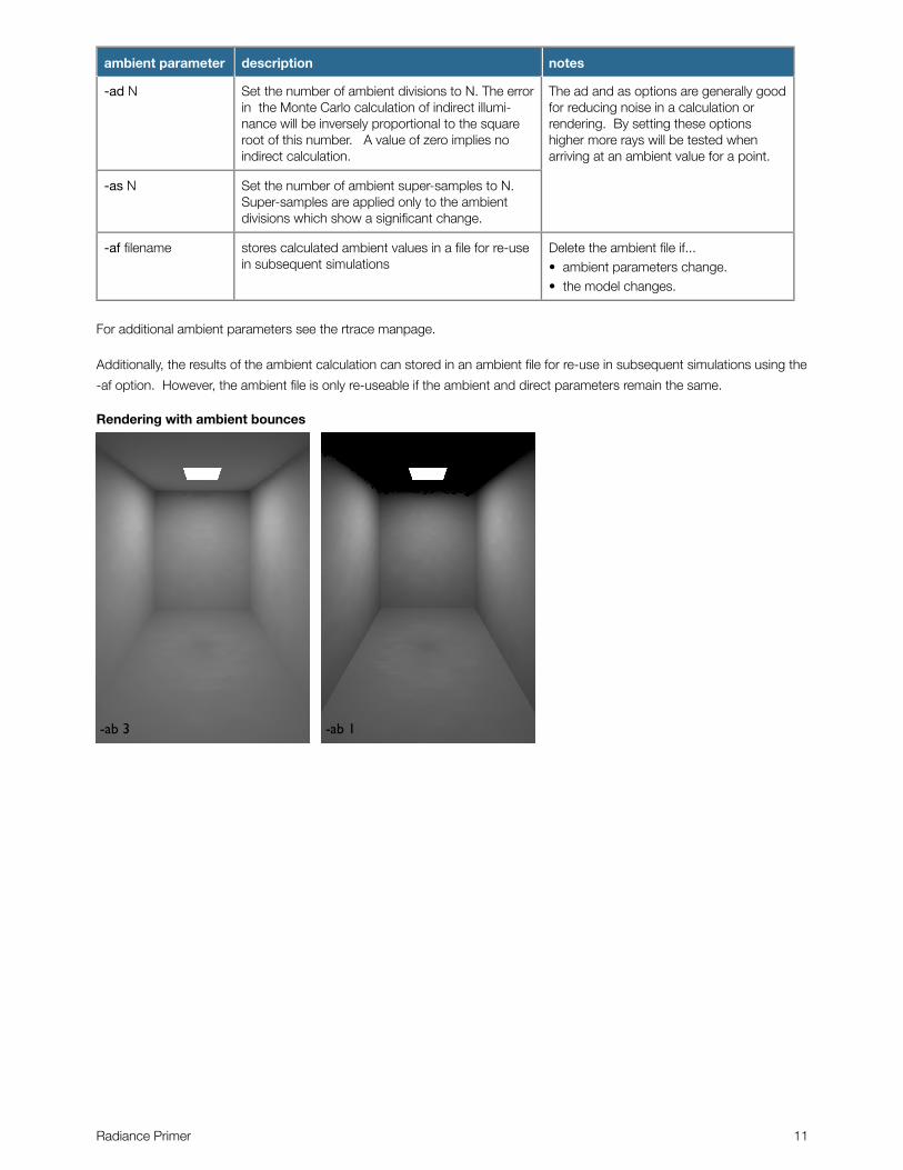
ambient parameter description notes
-ab N Set the number of ambient bounces to N. This is the maximum number of diffuse bounces com-puted by the indirect calculation. A value of zero implies no indirect calculation.
The number of ambient bounces is the most straight forward of the ambient parameters. It can be set based on the number of reflections typically required by the light to reach the task plus one or two extra for inter reflection within the space.
-ar res Set the ambient resolution to res. This number will determine the maximum density of ambient values used in interpolation. Error will start to in-crease on surfaces spaced closer than the scene size divided by the ambient resolution. The maximum ambient value density is the scene size times the ambient accuracy (see the -aa op-tion below) divided by the ambient resolution.
The ambient resolution generally sets the distance between ambient calculations.
Radiance Primer 10
ambient parameter description notes
-ad N Set the number of ambient divisions to N. The error in the Monte Carlo calculation of indirect illumi-nance will be inversely proportional to the square root of this number. A value of zero implies no indirect calculation.
The ad and as options are generally good for reducing noise in a calculation or rendering. By setting these options higher more rays will be tested when arriving at an ambient value for a point.
-as N Set the number of ambient super-samples to N. Super-samples are applied only to the ambient divisions which show a significant change.
-af filename stores calculated ambient values in a file for re-use in subsequent simulations
Delete the ambient file if...• ambient parameters change.• the model changes.
For additional ambient parameters see the rtrace manpage.
Additionally, the results of the ambient calculation can stored in an ambient file for re-use in subsequent simulations using the
-af option. However, the ambient file is only re-useable if the ambient and direct parameters remain the same.
Rendering with ambient bounces
-ab 3 -ab 1
Radiance Primer 11
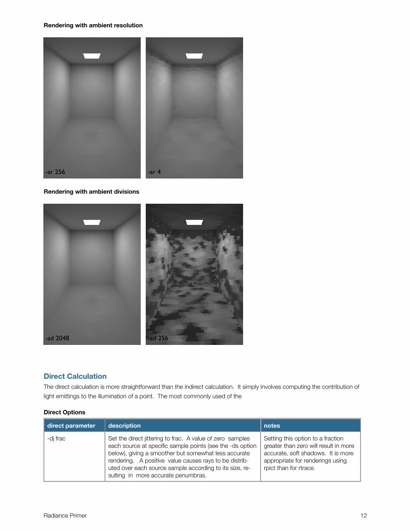
Rendering with ambient resolution
-ar 256 -ar 4
Rendering with ambient divisions
-ad 2048 -ad 256
Direct CalculationThe direct calculation is more straightforward than the indirect calculation. It simply involves computing the contribution of
light emittings to the illumination of a point. The most commonly used of the
Direct Options
direct parameter description notes
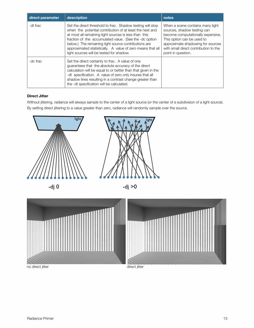
-dj frac Set the direct jittering to frac. A value of zero samples each source at specific sample points (see the -ds option below), giving a smoother but somewhat less accurate rendering. A positive value causes rays to be distrib-uted over each source sample according to its size, re-sulting in more accurate penumbras.
Setting this option to a fraction greater than zero will result in more accurate, soft shadows. It is more appropriate for renderings using rpict than for rtrace.
Radiance Primer 12
direct parameter description notes
-dt frac Set the direct threshold to frac. Shadow testing will stop when the potential contribution of at least the next and at most all remaining light sources is less than this fraction of the accumulated value. (See the -dc option below.) The remaining light source contributions are approximated statistically. A value of zero means that all light sources will be tested for shadow.
When a scene contains many light sources, shadow testing can become computationally expensive. This option can be used to approximate shadowing for sources with small direct contribution to the point in question.
-dc frac Set the direct certainty to frac. A value of one guarantees that the absolute accuracy of the direct calculation will be equal to or better than that given in the -dt specification. A value of zero only insures that all shadow lines resulting in a contrast change greater than the -dt specification will be calculated.
Direct Jitter
Without jittering, radiance will always sample to the center of a light source (or the center of a subdivision of a light source).
By setting direct jittering to a value greater than zero, radiance will randomly sample over the source.
-dj 0 -dj >0
light light
no direct jitter direct jitter
Radiance Primer 13
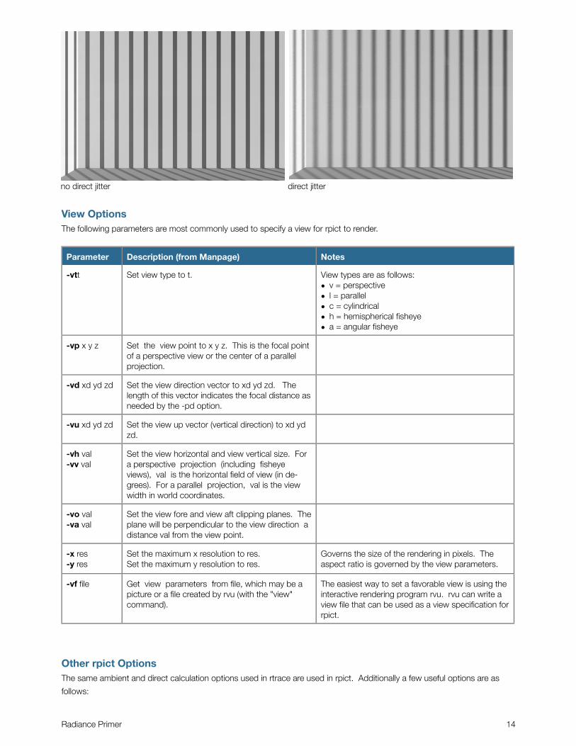
no direct jitter direct jitter
View OptionsThe following parameters are most commonly used to specify a view for rpict to render.
Parameter Description (from Manpage) Notes
-vtt Set view type to t. View types are as follows:• v = perspective• l = parallel• c = cylindrical• h = hemispherical fisheye• a = angular fisheye
-vp x y z Set the view point to x y z. This is the focal point of a perspective view or the center of a parallel projection.
-vd xd yd zd Set the view direction vector to xd yd zd. The length of this vector indicates the focal distance as needed by the -pd option.
-vu xd yd zd Set the view up vector (vertical direction) to xd yd zd.
-vh val -vv val
Set the view horizontal and view vertical size. For a perspective projection (including fisheye views), val is the horizontal field of view (in de-grees). For a parallel projection, val is the view width in world coordinates.
-vo val-va val
Set the view fore and view aft clipping planes. The plane will be perpendicular to the view direction a distance val from the view point.
-x res-y res
Set the maximum x resolution to res.Set the maximum y resolution to res.
Governs the size of the rendering in pixels. The aspect ratio is governed by the view parameters.
-vf file Get view parameters from file, which may be a picture or a file created by rvu (with the "view" command).
The easiest way to set a favorable view is using the interactive rendering program rvu. rvu can write a view file that can be used as a view specification for rpict.
Other rpict OptionsThe same ambient and direct calculation options used in rtrace are used in rpict. Additionally a few useful options are as
follows:
Radiance Primer 14
Parameter Description (from Manpage) Notes
-i Boolean switch to compute irradiance rather than radiance values.
This option is useful for creating iluminance
falsecolor and countour images.
-x res -y res sets output image size in pixels
-t sec Set the time between progress reports to sec. this option is useful for keeping tabs of the progress
of the rendering.
For a complete list of rpict options see the manpage.
rpict syntax revisited
generic syntax:
rpict [options] model.oct > image.pic
for example:
rpict -ab 3 -vf view.vf model.oct > image.picrpict -ab 2 -ar 256 -vf view.vf -af model.amb mo.oct > img1.picrpict -vth -vp 0 0 0 -vd 0 0 1 -vu 0 1 0 -ab 1 mo.oct > img2.pic
Radiance Primer 15
rtraceThe rtrace program is used to calculate radiance and irradiance, the output is typically an RGB numerical value. The input to
rtrace is coordinates of a point and a vector direction or a list of points and directions. Input is taken from the standard
input, which means it is either piped from another program to rtrace or read from a file using the ‘<’ operator. Input should
be in the following format:
xorg yorg zorg xdir ydir zdir
To read origin and direction from a file, the following syntax is used:
rtrace [options] model.oct < input.dat > output.dat
Rtrace will calculate the radiance looking from the point in the given direction. The RGB irradiance can be converted to
luminance using the following equation:
luminance = 47.4*R_rad + 120*G_rad + 11.6*B_rad
Options for rtrace can be broken into the following categories:
• Ambient Simulation Parameters
• Direct Simulation Parameters
• Other options
The ambient and direct simulation parameters are the same as those used by rpict.
Parameter Description (from Manpage) Notes
-o
specifies output for example:
v : value
p : point of intersection
-I
calculates irradiance interpreting input and
direction as the location and orientation of a
measurement point.
-i calculates irradiance instead of radiance
The desired output of radiance is specified using the -o option. the default is to output the RGB radiance/irradiance.
Alternatively, origin, direction, intersection, surface normal at intersection and many other options can be output. See the
rtrace manual page for other output options.
Irradiance Calculation
When the option -I (capitol I) is used to calculate irradance, the coordinate is interpreted as a measurement point and the
direction as the measurement orientation. One could imagine placing an illuminance meter at the given coordinates and
facing it in the given direction to take a reading. This option is useful for calculation illuminance within a space.
rtrace -I [other options] model.oct < input.dat > output.dat
illuminance = 47.4*R_irrad + 120*G_irrad + 11.6*B_irrad
When the option -i (lowercase i) is used to calculate irradiance, a ray is cast from the given point in the given direction.
Where the ray intersects a surface, an irradiance calculation is performed.
Radiance Primer 16
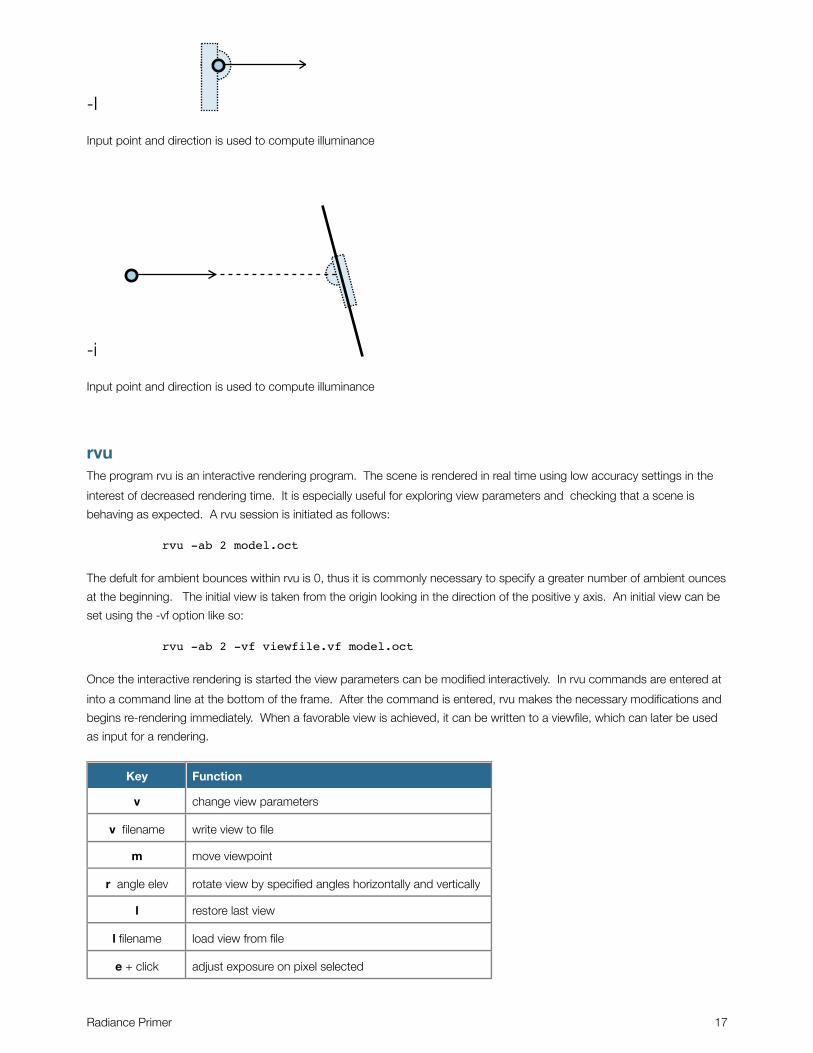
-I
Input point and direction is used to compute illuminance
-i
Input point and direction is used to compute illuminance
rvuThe program rvu is an interactive rendering program. The scene is rendered in real time using low accuracy settings in the
interest of decreased rendering time. It is especially useful for exploring view parameters and checking that a scene is
behaving as expected. A rvu session is initiated as follows:
rvu -ab 2 model.oct
The defult for ambient bounces within rvu is 0, thus it is commonly necessary to specify a greater number of ambient ounces
at the beginning. The initial view is taken from the origin looking in the direction of the positive y axis. An initial view can be
set using the -vf option like so:
rvu -ab 2 -vf viewfile.vf model.oct
Once the interactive rendering is started the view parameters can be modified interactively. In rvu commands are entered at
into a command line at the bottom of the frame. After the command is entered, rvu makes the necessary modifications and
begins re-rendering immediately. When a favorable view is achieved, it can be written to a viewfile, which can later be used
as input for a rendering.
Key Function
v change view parameters
v filename write view to file
m move viewpoint
r angle elev rotate view by specified angles horizontally and vertically
l restore last view
l filename load view from file
e + click adjust exposure on pixel selected
Radiance Primer 17
Key Function
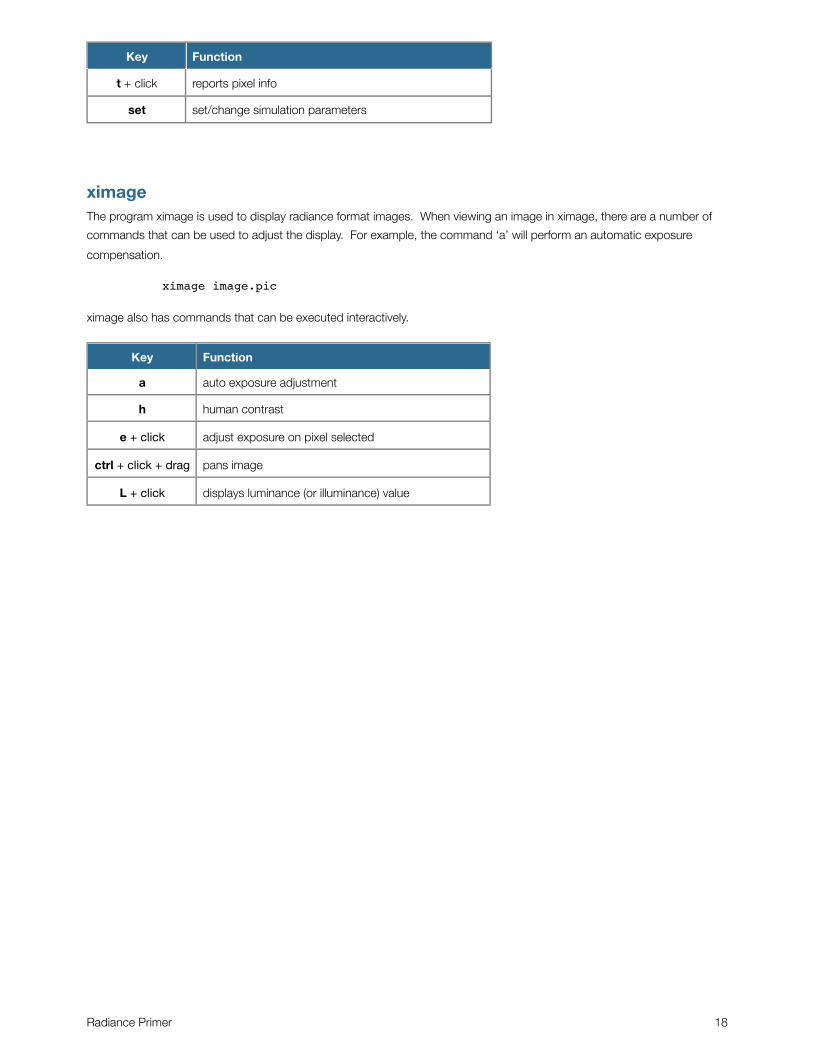
t + click reports pixel info
set set/change simulation parameters
ximageThe program ximage is used to display radiance format images. When viewing an image in ximage, there are a number of
commands that can be used to adjust the display. For example, the command ‘a’ will perform an automatic exposure
compensation.
ximage image.pic
ximage also has commands that can be executed interactively.
Key Function
a auto exposure adjustment
h human contrast
e + click adjust exposure on pixel selected
ctrl + click + drag pans image
L + click displays luminance (or illuminance) value
Radiance Primer 18
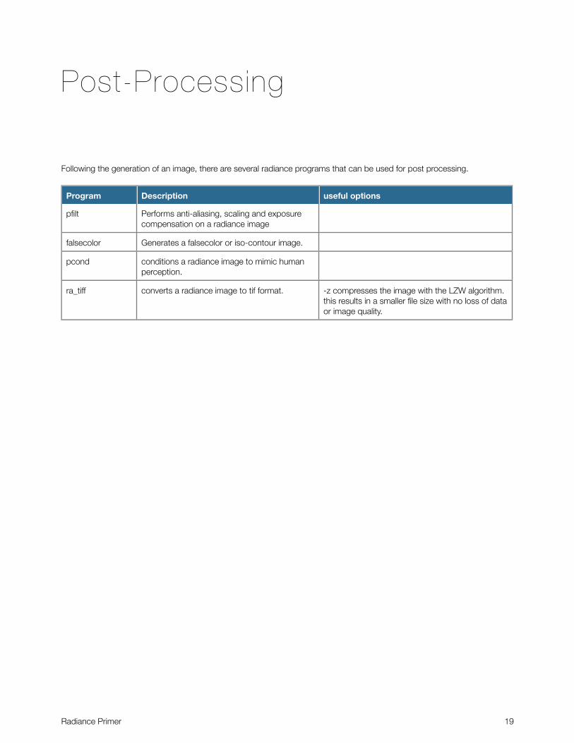
Post-Processing
Following the generation of an image, there are several radiance programs that can be used for post processing.
Program Description useful options
pfilt Performs anti-aliasing, scaling and exposure compensation on a radiance image
falsecolor Generates a falsecolor or iso-contour image.
pcond conditions a radiance image to mimic human perception.
ra_tiff converts a radiance image to tif format. -z compresses the image with the LZW algorithm. this results in a smaller file size with no loss of data or image quality.
Radiance Primer 19