02_v5_gpsfordesigner_ws_2_030402
DESCRIPTION
WorShop_2TRANSCRIPT
WS2-1
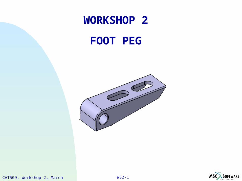
WORKSHOP 2
FOOT PEG
CAT509, Workshop 2, March 2002

WS2-2CAT509, Workshop 2, March 2002

WS2-3CAT509, Workshop 2, March 2002
Problem Description A new All Terrain Vehicle (ATV) is being designed to carry two people – a driver and a
passenger. An area of concern is the Foot Peg for the passenger on the ATV. The Foot Peg needs to be small due to limited space on the ATV yet able to handle the force of the passenger during the ride.
Analyze the Foot Peg as an aluminum part in the preliminary design phase to check for part failure in a static condition.
WORKSHOP 2 - FOOT PEG
WS2-4CAT509, Workshop 2, March 2002
Suggested Exercise Steps
1. Open the existing CATIA part in the Part Design workbench.
2. Apply aluminum material properties to the part.
3. Create a new CATIA analysis document (.CATAnalysis).
4. Apply the restraint condition.
5. Apply the load condition.
6. Compute the analysis.
7. Visualize the analysis results.
8. Save the analysis document.
WORKSHOP 2 - FOOT PEG
WS2-5CAT509, Workshop 2, March 2002
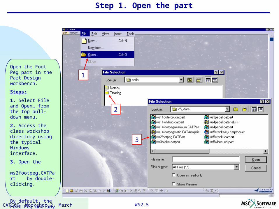
Open the Foot Peg part in the Part Design workbench.
Steps:
1. Select File and Open… from the top pull-down menu.
2. Access the class workshop directory using the typical Windows interface.
3. Open the ws2footpeg.CATPart by double-clicking.
By default, the Foot Peg and any other CATPart document is opened in Part Design workbench.
Step 1. Open the part
1
2
3
WS2-6CAT509, Workshop 2, March 2002
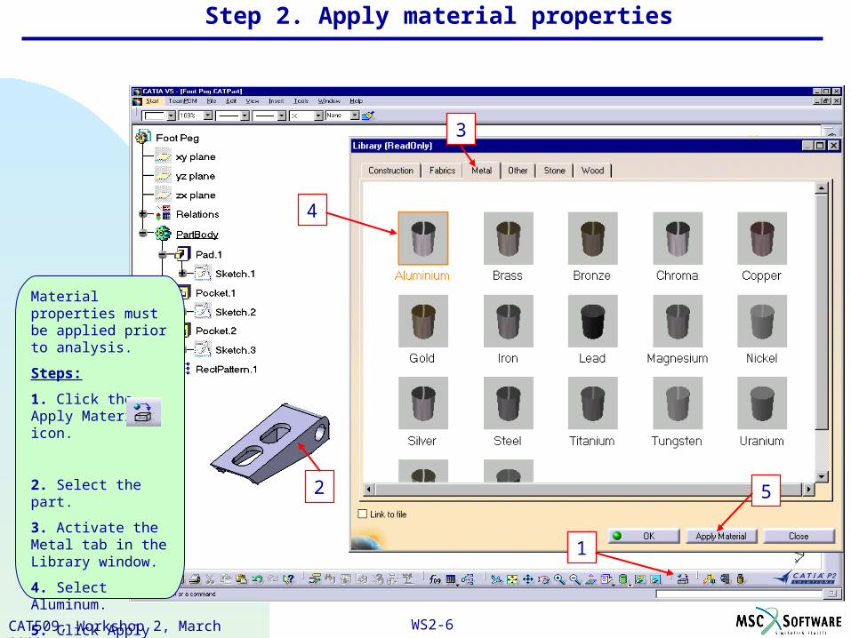
Material properties must be applied prior to analysis.
Steps:
1. Click the Apply Material icon.
2. Select the part.
3. Activate the Metal tab in the Library window.
4. Select Aluminum.
5. Click Apply Material button…OK.
1
2 5
3
4
Step 2. Apply material properties
WS2-7CAT509, Workshop 2, March 2002
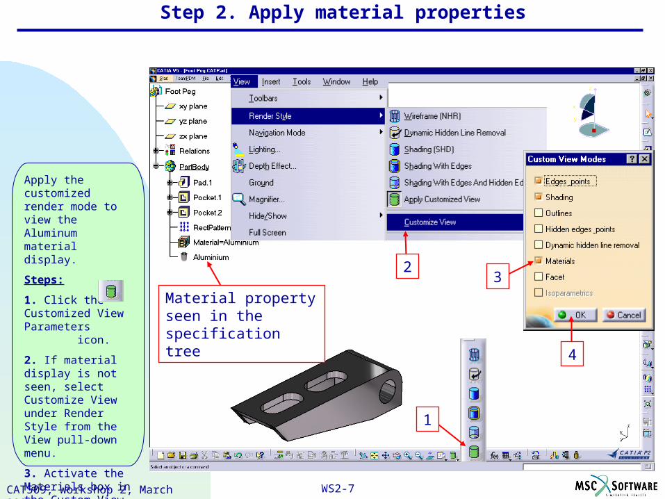
Apply the customized render mode to view the Aluminum material display.
Steps:
1. Click the Customized View Parameters icon.
2. If material display is not seen, select Customize View under Render Style from the View pull-down menu.
3. Activate the Materials box in the Custom View Modes definition window.
4. Click OK.
Step 2. Apply material properties
1
2Material property seen in the specification tree
23
4
WS2-8CAT509, Workshop 2, March 2002
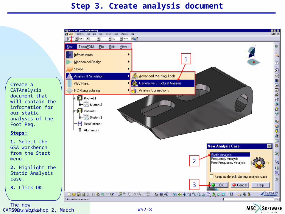
Create a CATAnalysis document that will contain the information for our static analysis of the Foot Peg.
Steps:
1. Select the GSA workbench from the Start menu.
2. Highlight the Static Analysis case.
3. Click OK.
The new CATAnalysis document is now active in the GSA workbench.
2
3
Step 3. Create analysis document
1
WS2-9CAT509, Workshop 2, March 2002
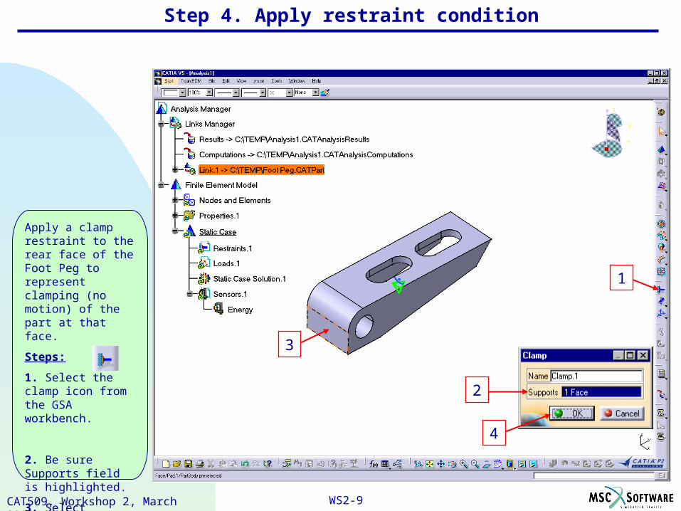
Apply a clamp restraint to the rear face of the Foot Peg to represent clamping (no motion) of the part at that face.
Steps:
1. Select the clamp icon from the GSA workbench.
2. Be sure Supports field is highlighted.
3. Select geometry to clamp (rear face).
4. Click OK.
1
Step 4. Apply restraint condition
2
4
3

WS2-10CAT509, Workshop 2, March 2002
The clamp restraint is created and seen in the specification tree.
Symbols appear on the part showing the clamp restraint applied to the rear surface of the Foot Peg.
Clamp symbols
Clamp created
Step 4. Apply restraint condition
WS2-11CAT509, Workshop 2, March 2002
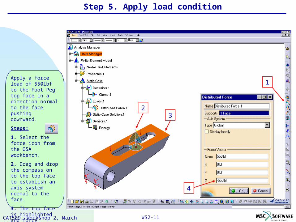
Apply a force load of 550lbf to the Foot Peg top face in a direction normal to the face pushing downward.
Steps:
1. Select the force icon from the GSA workbench.
2. Drag and drop the compass on to the top face to establish an axis system normal to the face.
3. The top face is highlighted and force vectors shown.
4. Key in value -550lbf for the Z vector…OK.
Step 5. Apply load condition
1
23
4

WS2-12CAT509, Workshop 2, March 2002
The force load is created and seen in the specification tree.
The force load is applied to the top face in a downward direction as shown by the vector arrows.
Hint: Drag and drop the compass back to its normal position away from the part after use.
Force created
Force direction arrows
Step 5. Apply load condition
WS2-13CAT509, Workshop 2, March 2002
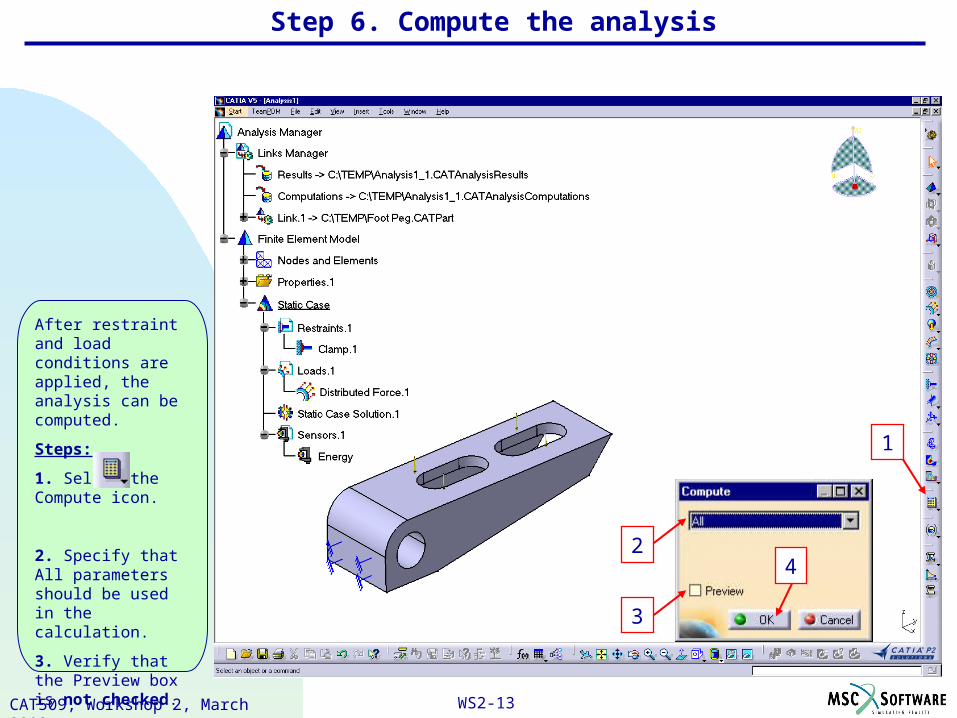
After restraint and load conditions are applied, the analysis can be computed.
Steps:
1. Select the Compute icon.
2. Specify that All parameters should be used in the calculation.
3. Verify that the Preview box is not checked.
4. Click OK.
Step 6. Compute the analysis
42
1
3
WS2-14CAT509, Workshop 2, March 2002
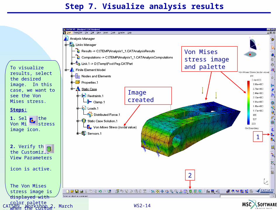
To visualize results, select the desired image. In this case, we want to see the Von Mises stress.
Steps:
1. Select the Von Mises stress image icon.
2. Verify that the Customized View Parameters icon is active.
The Von Mises stress image is displayed with color palette when the custom view mode is active.
Von Mises stress image and palette
Image created
Step 7. Visualize analysis results
1
2

WS2-15CAT509, Workshop 2, March 2002
For detailed results, query the maximum Von Mises stress values for the analysis.
Steps:
1. Select the Informations icon.
2. Select the Von Mises stress image if necessary.
The information window shows the minimum and maximum Von Mises stress values as well as the material yield strength of aluminum.
From this initial analysis the part will not fail
Max Von Mises stress is lower than material yield strength
Step 7. Visualize analysis results
1
2
WS2-16CAT509, Workshop 2, March 2002
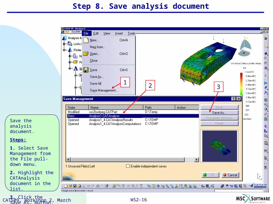
Save the analysis document.
Steps:
1. Select Save Management from the File pull-down menu.
2. Highlight the CATAnalysis document in the list.
3. Click the Save As… button.
13
Step 8. Save analysis document
2

WS2-17CAT509, Workshop 2, March 2002
Steps:
4. Select the directory path.
5. Key in Foot Peg Static for the analysis document name.
6. Click Save.
7. Notice the new name and Action “Save” for the analysis document.
8. Click OK to execute the noted Actions.
4
5
8
Step 8. Save analysis document
6
7

WS2-18CAT509, Workshop 2, March 2002