020-1209-00a matrix multi-touch user guideassets.techedu.com › assets › 1 › 26 ›...
TRANSCRIPT

Matrix MultiTouchUser Guide

Copyright © 1 Feb 2013 by Planar Systems, Inc. All rights reserved.Contents of this publication may not be reproduced in any form without permission of Planar Systems, Inc.
Trademark Credits Windows™ is a trademark of Microsoft Corp.All other companies are trademarks or registered trademarks of their respective companies.
DisclaimerThe information contained in this document is subject to change without notice. Planar Systems, Inc. makes no warranty of any kind with regard to this material. While every precaution has been taken in the preparation of this manual, the Company shall not be liable for errors or omissions contained herein or for incidental or consequential damages in connection with the furnishing, performance, or use of this material.
Warranty and Service PlansPlanar warranty and service plans will help you maximize your investment by providing great support, display uptime, and performance optimization. From post-sale technical support to a full suite of depot services, our services are performed by trained Planar employees. When you purchase a Planar product, you get more than a display, you get the service and support you need to maximize your investment. To find the latest warranty and service information regarding your Planar product, please visit http://www.planarcontrolroom.com/support
RoHS Compliance StatementThe Matrix MultiTouch display is fully RoHS compliant.
Part Number: 020-1209-00A

Matrix MultiTouch User Guide i
Table of ContentsIntroduction . . . . . . . . . . . . . . . . . . . . . . . . . . . . . . . . . . . . . . . . . . . . . . . . . . . . . . . . . . . . . . . . . . . . . . . . . . . . . . . . . . . . . . .1
The ERO Advantage . . . . . . . . . . . . . . . . . . . . . . . . . . . . . . . . . . . . . . . . . . . . . . . . . . . . . . . . . . . . . . . . . . . . . . . . . . . . . .1
Modular Protective Touch Surface . . . . . . . . . . . . . . . . . . . . . . . . . . . . . . . . . . . . . . . . . . . . . . . . . . . . . . . . . . . . . . . .2
Ultra-Slim Profile . . . . . . . . . . . . . . . . . . . . . . . . . . . . . . . . . . . . . . . . . . . . . . . . . . . . . . . . . . . . . . . . . . . . . . . . . . . . . . . . .2
Easy Installation and Configuration . . . . . . . . . . . . . . . . . . . . . . . . . . . . . . . . . . . . . . . . . . . . . . . . . . . . . . . . . . . . . . .2
Tools/Equipment List . . . . . . . . . . . . . . . . . . . . . . . . . . . . . . . . . . . . . . . . . . . . . . . . . . . . . . . . . . . . . . . . . . . . . . . . . . . . . .3
Unpacking and Checking Sheet Metal Contents . . . . . . . . . . . . . . . . . . . . . . . . . . . . . . . . . . . . . . . . . . . . . . . . . . .3
Unpacking and Checking Sensor Contents . . . . . . . . . . . . . . . . . . . . . . . . . . . . . . . . . . . . . . . . . . . . . . . . . . . . . . . .5
Accessory Box . . . . . . . . . . . . . . . . . . . . . . . . . . . . . . . . . . . . . . . . . . . . . . . . . . . . . . . . . . . . . . . . . . . . . . . . . . . . . . . . . . . .6
Assembling the Sensor Frame . . . . . . . . . . . . . . . . . . . . . . . . . . . . . . . . . . . . . . . . . . . . . . . . . . . . . . . . . . . . . . . . . . . . .7
Installing the Assembly Inspection Tool . . . . . . . . . . . . . . . . . . . . . . . . . . . . . . . . . . . . . . . . . . . . . . . . . . . . . . . . . 11
Assembling the Sheet Metal Frame . . . . . . . . . . . . . . . . . . . . . . . . . . . . . . . . . . . . . . . . . . . . . . . . . . . . . . . . . . . . . . 13
Testing the Sensor Frame Assembly . . . . . . . . . . . . . . . . . . . . . . . . . . . . . . . . . . . . . . . . . . . . . . . . . . . . . . . . . . . . . 15
Troubleshooting Issues With the Assembly Inspect Tool Software . . . . . . . . . . . . . . . . . . . . . . . . . . . . . . . . 17
Installing the MultiTouch Driver Software . . . . . . . . . . . . . . . . . . . . . . . . . . . . . . . . . . . . . . . . . . . . . . . . . . . . . . . 19
Specifications . . . . . . . . . . . . . . . . . . . . . . . . . . . . . . . . . . . . . . . . . . . . . . . . . . . . . . . . . . . . . . . . . . . . . . . . . . . . . . . . . . . . 22
Sensor Assembly Drawing . . . . . . . . . . . . . . . . . . . . . . . . . . . . . . . . . . . . . . . . . . . . . . . . . . . . . . . . . . . . . . . . . . . . . . . 23
Contact Information . . . . . . . . . . . . . . . . . . . . . . . . . . . . . . . . . . . . . . . . . . . . . . . . . . . . . . . . . . . . . . . . . . . . . . . . . . . . . 24

Table of Contents
ii Matrix MultiTouch User Guide

Matrix MultiTouch User Guide 1
IntroductionFor customers looking for a large, interactive display in public spaces or collaboration environments, Planar's Clarity™ Matrix MultiTouch Video Wall System provides an ultra-slim profile, high-impact interactive video wall. Planar’s Clarity Matrix MultiTouch utilizes a touch sensor frame around the edge of the video wall allowing multiple users to touch and use gestures to interact with content on the video wall. Clarity Matrix MultiTouch utilizes Planar's ERO™ (Extended Ruggedness and Optics™) technology to provide a modular, near seamless touch surface that protects the LCD screens.
Clarity Matrix MultiTouch incorporates the latest touch technology to enable up to 32 touch points simultaneously across the video wall. This allows multiple touches or common gesture recognition by a single user but allows for multiple people to interact with the video wall and not affect other users, making it the premier solution for customers looking to expand their collaboration capabilities in visualization or conference room applications.
Not only does the Clarity Matrix MultiTouch provide simultaneous touches but it provides a better touch experience with pinpoint accuracy, prevents false touch points, and is capable of creating large video wall sizes up to a 300” diagonal.
Caution: Windows 7 does not support more than one touch monitor. If you are planning to drive the Matrix displays at native resolution with multiple outputs, you will want to select a graphics card that can treat the desktop as one monitor on the Windows Operating System. The touch screen will only be able to interface and work with the primary monitor. Professional cards such as Nvidia Quadro, AMD Firepro and Datapath are examples of cards that support the capability of having multiple outputs but that treat the entire desktop as one.
The ERO AdvantageClarity Matrix with ERO features a glass front to provide increased ruggedness and optical performance for applications in public spaces or interactive touch. The glass surface is optically bonded to the front of the LCD with a proprietary construction and assembly technique to maintain the narrow bezel spacing and creating a continuous surface when tiled together in a video wall. Clarity Matrix with ERO also provides improved optical performance by providing additional ambient light rejection and increased contrast.
Without ERO With ERO
Planar's ERO technology features an optically-bonded glass front for increased ruggedness and optical performance

Modular Protective Touch Surface
2 Matrix MultiTouch User Guide
Modular Protective Touch SurfaceOther implementations of touch systems for LCD video walls have required a large piece of glass in front of the LCD to protect and provide a touchable surface. This glass can be cumbersome for installation, transport, and servicing of large video walls. The modular design of the Clarity Matrix with ERO provides a near seamless touch surface while ensuring ease of installation and serviceability, less parallax error, and superior optical properties.
Ultra-Slim ProfileClarity Matrix MultiTouch features an ultra-slim profile with Planar’s EasyAxis™ Mounting System. The EasyAxis Mounting System also enables fine adjustments to achieve perfect panel-to-panel alignment, creating a continuous touch surface.
Easy Installation and ConfigurationClarity Matrix MultiTouch is available in 2 x 2 and 3 x 3 standard video wall configurations. Custom configurations up to 300” diagonal are available as a special order item. Both standard and custom configurations are available in 6 or 32 touch point options. This modular system is easy to install and includes everything needed to add multi-touch capabilities to the video wall and is installed and calibrated during the installation.
Modular design created continuous touch surface

Tools/Equipment List
Matrix MultiTouch User Guide 3
Tools/Equipment ListDepending on your installation, you may need one or more of the following:
• At least two people to hang the assembled sensor frame pieces
• 2.5mm Hex screwdriver
• #1 Phillips screwdriver
Unpacking and Checking Sheet Metal ContentsThe following items are included in the sheet metal box.
Part Description Quantity Picture
Side mounts (L,R)* For each LCD in the left and right outer column of the video wall. Note that the mount is the same for each side.
2 x 2 wall: 43 x 3 wall: 6*Custom configurations may contain a different number of side pieces.
Side covers (L, R) For each LCD in the left and right outer column of the video wall.
2 x 2 wall: 43 x 3 wall: 6*Custom configurations may contain a different number of side pieces.
Note: The side covers look similar to the top/bottom covers.

Unpacking and Checking Sheet Metal Contents
4 Matrix MultiTouch User Guide
Top/bottom mounts For each LCD in the top and bottom rows of the video wall.
2 x 2 wall: 43 x 3 wall: 6*Custom configurations may contain a different number of side pieces.
Top/bottom covers For each LCD in the top and bottom rows of the video wall.
2 x 2 wall: 43 x 3 wall: 6*Custom configurations may contain a different number of side pieces.
Touch sensor mount clips
2 x 2 wall: 163 x 3 wall: 24*Custom configurations will contain two per mount
M4 screws Hex head black screws used to secure clips and mounts.
1 per clipMount - number varies based on size of wallTop and bottom covers - number varies based on size of wall4 per corner covers
Part Description Quantity Picture

Unpacking and Checking Sensor Contents
Matrix MultiTouch User Guide 5
Unpacking and Checking Sensor ContentsThe following items are included in the shipping box.
Part Description Quantity Picture
Side piecesRight (RE Y1, RE Y2)
Left (RE Y1, RE Y2)
2 x 2 wall: 43 x 3 wall: 6*Custom configurations may contain a different number of side pieces.
m3 x 10mm panhead Phillips screws
per side piece: 3per top piece: 5per bottom piece: 5
Top pieces(EM X1, EM X2)
Bottom pieces(EM X1, EM X2)
2 x 2 wall: 43 x 3 wall: 6

Accessory Box
6 Matrix MultiTouch User Guide
Accessory BoxThe following items are included in the accessory box.
Part Description Number Picture
Ribbon cable/Sensor connector
Cable attached to sensor. Extras are included in the box.
Depends on configuration
Power cable 1
Power adapter 1
USB cable Used to connect to the computer which has the Assembly Inspection Tool software installed, which is used to test the sensors.
1

Assembling the Sensor Frame
Matrix MultiTouch User Guide 7
Assembling the Sensor Frame
Caution: It is important that the video wall is flat and square so the LCD is not blocking the sensors from “seeing” across the surface of the video wall. We recommend that you spend extra time and attention to detail related to the alignment and squareness of the video wall prior to installing the touch sensors.
For ease of installation, we suggest that you assemble all of the sensor frame pieces before installing it on the wall. The process is fairly simple. Each frame piece that matches will have a corresponding number at one end. For example, two pieces will show 01 at the end of a piece. These two pieces both showing 01 should be connected.
Caution: Windows 7 does not support more than one touch monitor. If you are planning to drive the Matrix displays at native resolution with multiple outputs, you will want to select a graphics card that can treat the desktop as one monitor on the Windows Operating System. The touch screen will only be able to interface and work with the primary monitor. Professional cards such as Nvidia Quadro, AMD Firepro and Datapath are examples of cards that support the capability of having multiple outputs but that treat the entire desktop as one.
1 Once you unpack all of the sensor pieces, find the pieces that have a corner connection bar. Each piece will only have one side with this metal connection bar.

Assembling the Sensor Frame
8 Matrix MultiTouch User Guide
2 Place the corner pieces on the floor in the general layout of your wall. For example, if you have a 1 x 3 Portrait installation, line up the corner pieces as they would fit on the LCD wall.
3 Then find the corresponding pieces that attach to each corner piece. In the previous example, the corner piece is on the left side, labeled with 01. The top piece shown in the picture is also labeled 01. This is the corresponding piece. The example below shows two corner pieces that need to be connected.
4 Connect all corner pieces with the corresponding pieces.
5 Secure the pieces that have been connected by screwing in two m3 x 10mm screws.
6 Where there are gaps in the sensor assembly, look for the remaining pieces that correspond to each other. Again, match 02 with 02, 03 with 03, etc.

Assembling the Sensor Frame
Matrix MultiTouch User Guide 9
7 Secure the pieces that have been connected by screwing in three m3 x 10mm screws.
8 Once all side pieces are connected, then connect the ribbon cables between the pieces.

Assembling the Sensor Frame
10 Matrix MultiTouch User Guide
9 Once all pieces are secured with screws, and the ribbon cables connected, the sensor assembly should have the same shape and size as the LCD video wall onto which it will be mounted. Below is an example of an assembled sensor frame for a 1 x 3 Portrait video wall.

Installing the Assembly Inspection Tool
Matrix MultiTouch User Guide 11
Installing the Assembly Inspection Tool
In order to test the functionality of the sensor assembly, you first need to install the Multi touch Platform software (found on the enclosed CD-ROM) and then the Assembly Inspection Tool software (found on the enclosed USB drive).
1 Double click the pq_ait icon to install the software.
2 Click Install on the first window to continue.

Installing the Assembly Inspection Tool
12 Matrix MultiTouch User Guide
3 The following window appears as the installation is in process.
4 When the installation is finished, click the Next button to continue.
5 Click Finish on the final window to close the installation.

Assembling the Sheet Metal Frame
Matrix MultiTouch User Guide 13
Assembling the Sheet Metal Frame
1 Attach side mounts to each LCD using three M4 screws
2 Attach top and bottom mounts to each LCD using five M4 screws.
3 Using a straight edge ruler, align the fronts of the mounts so they are even with the front of the glass on the LCD.
Note: It is OK for the mounts to be slightly in front of the glass on the LCD. However, you do not want the mount to be behind the glass!

Assembling the Sheet Metal Frame
14 Matrix MultiTouch User Guide
4 Using at least two people, carefully lift up the assembled sensor frame and align it with the LCD panels.
5 As two people continue to hold the frame, have one person attach the sensor to the mount using the mount clips and M4 hardware to attach the covers.
6 In order to attach the mount clip, first turn it so it is perpendicular with the frame. Then move it into the slot.
7 Once it is in the slot, turn the mount clip so it is parallel with the frame.
8 When all of the clips are in place, verify the alignment of the sensor frame to the LCD panels.
9 Loosely attach the covers to the mounts using the M4 screws.
Caution: Don’t attach the corners until all of the sides, top and bottom covers are installed.
10 Using M4 screws, loosely attach the four corner covers.
11 Verify alignment one more time and then tighten all of the cover screws.

Testing the Sensor Frame Assembly
Matrix MultiTouch User Guide 15
Testing the Sensor Frame Assembly
The Assembly Inspect Tool software allows you to test the sensor assembly to make sure all of the sensors are working.
Caution: We highly suggest testing the sensor frame before you install it on wall because it will be easier to troubleshoot and fix issues.
1 Double click on the Assembly Inspection Tool icon to open the program.
2 If your computer is connected to the sensor assembly correctly, you will see a window similar to the following.
Test button
Show Ambient
The serials number of overlay
Main interface

Testing the Sensor Frame Assembly
16 Matrix MultiTouch User Guide
3 If you are connected using the G3P, you will see Back Side and Front Side buttons. You can switch back and forth between the front and back using these buttons.
4 After pressing the Test button, if your sensor assembly is working correctly, you’ll see the following message: “CONGRATULATIONS Test Passed.”

Troubleshooting Issues With the Assembly Inspect Tool Software
Matrix MultiTouch User Guide 17
5 When you choose “Show Ambient Light,” the intensity of the ambient light will be dynamically shown on the main interface.
Troubleshooting Issues With the Assembly Inspect Tool SoftwareBelow are some possible issues that might occur as you are installing and testing your sensor assembly.
Issue: After pressing the Test button, a red square appears in the bottom of the left corner and the following message appears in the top left corner: “WARNING! Segments connection error.”
Possible Cause: It is possible that the two boards in the bottom left are not connected.
Solution: Check the corner and make sure it is connected to your sensor assembly.

Troubleshooting Issues With the Assembly Inspect Tool Software
18 Matrix MultiTouch User Guide
Issue: After pressing the Test button, a single board turns red and the following alert message appears: “WARNING! Component not functioning.”
Possible Cause: The board might not be working. Contact Planar’s Technical Support for more information.
Issue: After pressing the Test button, the following alert message appears: “WARNING! Ambient light too strong.”
Possible Cause: The ambient light could be too strong.
Solution: Direct sunlight or other indoor light can cause interference with the touch sensor. Try repositioning the lighting around the video wall or block light coming from direct sunlight.

Installing the MultiTouch Driver Software
Matrix MultiTouch User Guide 19
Installing the MultiTouch Driver Software
1 Insert the driver CD into the computer which will be attached to the sensor assembly.
2 Copy the driver software onto the computer’s hard drive.
3 Then double click on the .exe file to start the software installation.
4 The following window appears. Click Next to continue.

Installing the MultiTouch Driver Software
20 Matrix MultiTouch User Guide
5 Click Install to start the installation.
6 You will see a window similar to the following during installation.

Installing the MultiTouch Driver Software
Matrix MultiTouch User Guide 21
7 When the installation is complete, click Next to continue.
8 Select one of the radio buttons shown above and then click Finish.

Specifications
22 Matrix MultiTouch User Guide
SpecificationsTouch Options MT6- 6 Simultaneous Touch Points
MT32- 32 Simultaneous Touch Points
Standard Configurations 2 x 2 and 3 x 3 MX46HD-L, 2 x 2 and 3 x 3 MX55L
Custom Configurations Height < 10 ft. (3 m)Width + Height < 33 ft. (10 m)
Portrait or LandscapeLX46, MX46HD, MX55, HX60
Connectivity to Source USB 2.0
Power for Touch System 100-240V AC, 50-60Hz (110V/220V typical)
Operating Voltage 5.0V typical
Operating Current 1500 mA typical
Peak Current 3000 mA maximum
Power Consumption 24W typical
Response Time 7-12 ms
LED Pitch 5.4 mm
OS Compatibility Windows 7, Windows XP, Mac OS X

Sensor Assembly Drawing
Matrix MultiTouch User Guide 23
Sensor Assembly Drawing
�����
����
��
��
�����
���
���
�����
���
��
����
����
����
� ��
����
����
�
�����
����
���
����
����
�
���
���
����
���
���
����
����
���
!��
��"��
���
!����
����
��
��
�����
���
���
�����
����
��
���
����
���
����
!��
��"��
���
�����
����
��
��
���
����
��
����
���
����
!��
��"��
���
����
� �
���
���
���
� �
���
����
�
Contact Information
24 Matrix MultiTouch User Guide
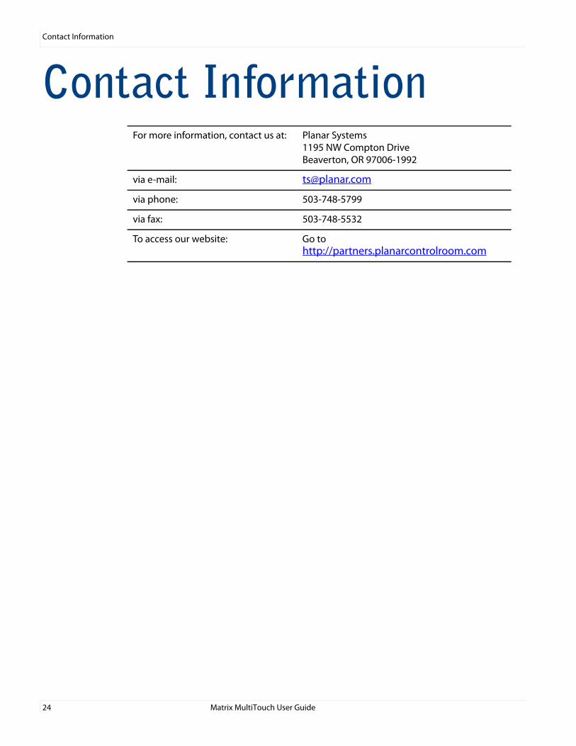
Contact InformationFor more information, contact us at: Planar Systems
1195 NW Compton DriveBeaverton, OR 97006-1992
via e-mail: [email protected]
via phone: 503-748-5799
via fax: 503-748-5532
To access our website: Go to http://partners.planarcontrolroom.com