02 - vertical milling in the home workshop
TRANSCRIPT

ARNe -_3 THROP VERTI MLLING IN THE
ME 0 K OP
l1J.J.J.1.illlillJ 1III111111 !11111111111111111111111 I1111I1111111 blllLJ..l.W.J..W..W.WJ..W.LL.Ll.W...I.LW.I..l.W.l..I.J.l.I..l.lJI

»
::IJ
G)
C
(J
)
a:J o o CJ)
"

Argus Books Argus House Bounda ry W ay Hemel Hempstead Hertfordshire HP2 7ST Eng la nd
First published 1977 Second im pression 1979 Sec ond edi ti o n 1984 Rep rin ted 1986, 1988, 1989, 1990, 1991. 1993
© A rg us Books Ltd 1977
All r ights reserved . No part of this publication m ay be reprod uced in any fo rm by print. photography, microfilm or any othe r means wi thout written permission from the publisher.
ISB N 0 852 42 843 x
Photot ypesetting by Perf o rm ance Typesetting, Milton Key nes
Printed and bound in G reat Br itain by Biddies Ltd . Guil d fo rd and Kin g 's Lynn
CONTENTS
Chapter One
Chapter Tw o
Chapter Three
Chap te r Four
Chapter Five
EVOLUTION OF THE VERTICAL MILLER 12 Early history of indu strial machines: mill ing in the early sma ll lathes: mi lling attachments for lat hes ci rca 19 20s: E.T, W estbury's experimental machine 1964: the Dare-Westbury machine 1968: curre ntly avail able sma ll machines and attachments,
MILLING FLAT SURFACES 27 Surfaces paralle l to table: simple fixed-radius f1 ycutt ers: var iab le-radius bor ing head flycutting: multiple -tooth face mills: work holding: mult ip lepass mi ll ing: surfaces square w it h table : using side of endmill.
SLITTING AND CUTTING 35 Use of slitting saw for cutting through machinery component bosses : eccentric sheaves and straps : mar ine type big ends of connecting rods.
KEYWAY CUTTING 37 Endmill ing round ended 'feath er' keyways : keyways on taper shafts : use of disc tvoe cutters for plain sunken keyways : \Noodru ff keyways: making Woodruff cutters in the home workshop : table of suggested sizes of \N oodruff keys and kevvvavs fo r model engineers,
FLUTING COMPONENTS OTHER THAN TOOLS 43 Correct form of flutes ir loco connecting and cou pling rods: mounting rods against anglepla te for flu ti ng : parallel flutes: taper flutes: preferred type of cutting too l.
Chapte r Six
Chapter Seven
Chapter Eight
Chapter Nine
Chapte r Ten
Chapter Eleven
BORING 45 Dealing with parts too large to swing in lathe: trepanning large ho les.
'J IG- BORING' 46 Using the miller as a measuring machine : drilling holes at one setting of work and precise cent res: eng ine beam: back-lash precautions: tri p gea r component : mu lti-ho le boiler plates.
PROFILING 49 Curves on parts too large for lathe: loco frames : smokebox castings : machine pad bolts: loco con nec ting rod s and coupling rod s.
END-ROUNDING 52 Use of hardened f ilin g gu ides deprecated: mounting work on rot ary table: sta ndard size guide plugs: anti-slip precau tio ns: direction of feed for exte rnal and i nte rnal surfaces.
DIVIDING HEADS 54 Simple ungeared div iding heads : using change w hee ls as index plates: examples of d ividing w ork : hexagons. squares. dog clutch teeth : avoiding odd numbers: the Myford worm-geared dividing head : avoiding back-lash erro rs : packing block for bringing to lathe centre height: universal steady stand fo r Myford head: three further dividing heads.
DIVIDING HEA DS AND GEAR-CUTT IN G 62 Limitations to strai ght spu r gears : sim ple head : M yford worm -geared head: tooth cutt ing on integral pi nion : use of home made I lvcut ters: Brown & Sharpe disc type cutters : selectio n of cutter to suit numb er of teet h : cutting a large coa rse tooth gear: anti-slip back-up devices ,
Chapt er Tw elve
Chapter Thirt een
Chapter Fourt een
Chapter Fifteen
Chapter Sixteen
DIVI DING HEADS AND TOOL MAK ING 66 Fluting taps : example 5-flute Acme tap : producing a small fine tooth milling cutter w ith ball end : use of table stop blocks: combination of rotary tabl e with ma in table movement: large 60 deg ree counte rsink fluting .
DIVIDING HEADS AND GRAD UATED SCALES 71 Cutti ng graduation marks: use of rotary 'engraving' cutters : use of non-r otating plani ng type tools : use of table stops to contro l line lengths: graduating cyli ndr ica l scales: gradua ting flat angular scales : checking correct way of figuring when stamping scales ,
CUTTER SPE EDS FOR VERTICAL MILLERS 74 Speeds affect ti me occupied on job: speeds too high may cause excessive cutter wear and chatter : rigidi ty of work, cutter and mac hine inferior as a rule to indust rial condi t ions, dry cutting instead of lubricated : Table III gives speeds for cutters in different kinds of tasks : machine speeds may not alwa ys be suitable.
WORK -HOLDING WITH D IFFICULT SHAPES 78 Comparison with full scale engi neering : use of chucking pieces on components : thin components and use of adhesives: advisability of making fixtures fo r difficul t pieces : three-s ided angleplates.
CHUCKS FOR MILLING CUTTERS 81 Never use taper shank tools or chucks without drawbar: chucks for screw ed shank self -tightening collets : Clarkson chuck : Dsborn Titanic chuck: Chucks for tee -headed locking cutters: Clare chucks : use of small end mills and D-bits withou t locking features : ph ilosophy of ' throw - aw ay ' cutters.

List of Illustrations
Fig. 1 Ab w ood mi llin g attac hment of the 1920s 13 2 E. T. W estb ury 's mill ing machine 14 3 Dore-W estbu ry machine 15 4 Dare-W estbury M k II machine 16 5 Rodney attachm ent 17 6 Rodney mach in e 18 7 Am olco attach men t 19 8 Amol co machine 20 9 M ent or mach ine 2 1
10 M aximat attachment 23 1 1 Astra mach ine 2 12 Tw in machi ne 22 13 Senior machine 26 14 Set of three fl ycutt ers 2 8 15 Flycutt ing a bracket 28 16 Flycutti ng connecting rod ends 29 17 Flycutting tapered bar mat eria l 29 18 Flycutting cy linde r soleplate 30 19 Facem il l 3 20 M illing f lywheel joint face 31 21 Mi ll ing crosshe ad slide 32 22 M ill ing bear ing jaw s in bedpl ate 33 23 Slitting boss of cast ing 35
4 Milli ng feath er kevw av 3 7 25 M illing feath er keyway on tap ered shaft 38 26 Mil ling keyway wi th slitting saw 39 27 Set of four Woodruff keyway cutters 39 28 M ill ing W oodruff kevwav 4 1
29 Fluting locomo tive connect ing rod 4 4 30 Draw ing of steam hook (lever) 4 7 3 1 Photograph of steam hook 48 32 Profiling pad bo lt 50 33 Profil ing coupling rods 50 34 End-rounding wi th rotary tabl e 53 35 Cutting teeth in dog clutch par t 5 5 36 Draw ing of steady stand for Myford div id ing head 56 37 Steady in use on a gear cutti ng opera tic 58 38 Thro p divid ing head 58 39 Thom as versat ile divid ing head 59 40 Kibbey/M .E.S. dividlnq head 60 4 1 Close-up of f lycut ter and pinion 63 4 2 Gearcu tt ing w ith Brown & Sharpe cutter 63 4 3 Fly cutt ing 10 d.p, gearwh eel. front view 64 44 Flycutt ing 10 d.p. gearw hee l. rear view 6 5 45 Flut ing A cm e thread tap 66 46 Cutt ing teeth of ball-end cu tt er 67 47 Close-up of ball-end cu tte r 68 48 Gashin g f lutes in large countersinking tool 69 49 Rear v iew showing steady stand in use 70 50 Cylindrical machine component being grad uated 72 5 1 Close -up of prev ious operat ion 72 52 Graduating part -ci rcul ar arcua te scal e on fl at surfa ce 73 53 Tape -he ld workpiece being flyc ut 79 54 Hern inpwav three-sided anglep late 79 55 Tw o of the th ree sizes of Herninqwav ang leplates 80 56 Clare mi ll ing chuck 82 57 Clarkson mi ll ing chuck 82 58 Osborn mill ing chuc k 83
Preface In th e engineering industry the vert ical miller is very widely used . no t only for batch product lorrbu t also for tool ma king and the 'one -off' jobs which are so common in general eng inee ring. In the home workshop. w her e most jobs are 'one-off' the versatility of th e machine makes it an import ant comp anion to the lathe. Thi s book des crib es many of the infinitely wide range of operations wh ich can be done. and all those described are illustrated by photographs so that understanding of the methods is assured . These cove r work on parts of model locomot ives. stationary engines machinery . cutt ing too ls. gea rs, clutches, etc. Full informat ion is given o n the machine accessories wh ich are requi red, suc h as var ious types of cutters and t he chucks needed for their mounting on the machi ne spind le. The use of cheap home-made cutt ers is shown and encouraged. Guidance is also give n on the work-holding dev ices such as clamps. packings, vices. angle plates, dividing heads. rotary table s, and w hich of these are needed for part icular kinds of work .

CHAPTER 1
Evolution of the Vertical Miller
The horizontal mi lling machine evo lved natura lly fr om the lathe in t he fi rst or seco nd decade of the nine tee nt h century. Eli W hitney (U.S.A.) is said to have had one in use about 18 18. and in Tools for the Job the lat e LTC. Rolt recount ed how the yo ung engineer James Nasmyth {later to become famous as the inventor of the stea m ham mer and ot her app liances l fixed one up and milled the fla ts on hundreds of tiny hexagon nuts for a model of a Maudslay marine engine. w hile working fo r Henry Ma udslay . Draw ings of the ear ly horizont al millers show suc h a resemb lance to the la thes of that period that almost certainly they were in fact lathes w hich had been adapt ed to mil ling. The cutters we re really f iles. made by the fi le makers of the t im es, using the 'handcu tt ing ' methods (really a hamm er and a spec ia l chisel) w hic h we re the only pract ice available at that time.
The evolut ion of the vertica l miller came natural ly afte r the ho rizontal machi ne. I have not found any reliable refe rence to a date by w hic h the vert ical miller had appeared in industry , thoug h this must have been we ll before 1900 .
W hen model eng ineering sta rted to beco me an esta bl ished hobby at the turn of the century quite a variety of sma ll
12
lathes we re provided by di fferent makers. and the great ver sat ili ty of the lathe created in itself a tendency to make the lathe do every opera tion that arose . This wa s enhan ced by the fact that ma ny modellers were working men with very litt le cash to spend on their hobby. Many we re the inge nious attachments devised to enable the lathe to carry out work it had never been intended to do . Such makers as Drummond Brothe rs modified their lathes with tee-slotted boring tables to help in this work . and even bro ught out the famous ro und-bed lathe. wh ich although intended for a cut -price market. also had bu ilt into it the abi lity to do a lot more than just simple turning . But as the years wen t by it became ever more appa rent something better was needed for mi lling operations . No ne of the small mille rs produced by the mac hine tool industry we re oriented towards the home workshop,
Then in the 1920s the Abwcod Tool and Engi neering Co. produced an exce llent vertical mi lling at tachmen t fo r mounting on smal l lathes. especia lly the popula r 3t in. flat bed Drummond . though adjustable features made it applicable to othe r lat hes too . It had a No. 1 Morse tape r arbor which fitted in to the lathe
[},'\
j:ig . t Abv/ood milling attachment of the 19205
13

spindl e. and bevel gears with keywa yed shafts took the drive up to the vert ica l cutt er spind le. w hic h had a No. 1 Morse interna l taper. A ll the gears w ere equa l rat io mit re beve ls. so the cutter rotated at the sam e speed as th e lathe spindle . and all the six speeds of the lathe were usable. The w ork wa s mounted on the lathe bo ring table. and power feeding in one direction came from the lathe screwcutt ing gear. A phot ograph of this uni t set up on a Myford Super 7 is show n in Fig. 1. It wa s unfortuna tely a low -vol ume. labou r intensive uni t w it h vee slides needing hand scrapi ng . but w as sell ing in 19 30 for 7 guin eas. about a quar ter of the cost of
the Drummond lathe. A lt hough out of producti on for ma ny years now . it was in i ts time a co urage ous effo rt . but belonged to the age w hen most home lathes were driven by fla t belt fro m a tread le or cou ntarshaft. and the cost of electric motors made th e in dependen t mo tor drive uneconom ic in home hobb y appli cations.
Bu t th e need for a handy vertica l mil ling ma chine had been recogn ised. and in the ear ly 1960s that very good friend of model engineers. Edgar T. W estbury . com plete d an expe r imenta l m achi ne. wh ich he desc ribed w it h drawings and pho tog rap hs in the Model Eng ineer during 19 64 . That too wa s a very labour
Fig. 2 E.T. Westbury 's
milling machine
ig, 3 Dore-Westbury machine
intensive machine w ith vee slides, and the main cast ings w ere m uch too big to be machi ned in th e average home workshop. A t that time he w as una ble to find any engi neering fir m wi lli ng to take it over and manufacture it. or even to do the machining on a contract basis at such a price as it was thought model engi neers would be wl llinq to pay.
Three years later I found myself with the opportunity to tak e a fresh loo k at th is design, which he had di scussed w ith me during the experimental pe riod. I evolved a new set of d rawings for a sim ilar machi ne, but using flat slideways more economically constructed. a reducti on gear for low er bottom speeds, hollow spindl e for a drawbar. and othe r changes
intended to make econom ies or improve the pe rformance . This new design was discussed w ith Edgar. w ho agreed to the use of the name 'Dore-Westburv ' , the machine to be sold as a kit of sem ifi nished components by my existing firm Dore Engineering, I was abl e to place the machining of the componen ts w ith a number of firms alread y know n to me . and the fi rst sets of materials began to go out to custo mers early in 1968. Since that t im e many hundreds of sets have bee n distributed . all over the wo rld . and are still being made in ever grea te r quant iti es by M o d e l En g i ne e r i n g S erv i ce s. o f Chesterf ield . w ho too k i t over from me in 19 7 1, w hen I wa nted , on acco unt of age , to reduce my comm itmen ts ,
Castings to the original design are, however, st ill available from Waking Prec is io n M odels of 16 Dovecot Park . Aberdour. Fife. Scot land KY3 OTA . and a machine fro m these is show n in Fig. 2. The Dare-W estbu ry mac hine is depicted in Fig. 3 and the sim ilarity be tween them wi ll be at once appa rent. Du ring its ent ire life the Dar e-Westbury has been undergoing sma ll improvements. and the present supplie rs have now dec ided that t he m od i f i c a t i o n s a re s u ff ic ie n t ly stabilised for the present version to be ti t led the M ark II model. From now on all machines supplied w ill be of this form. though st ill subject to certain optional vari ations which customers w ill be able to select as they wi sh.
The more importan t changes include an increase in the quill travel from 2i in. to 4-1- in . Ext ra pull ey steps with a new type of belt extend the speed rang e sligh t ly fro m 32 to 1880 r.p.m. w ith more intermediates. provid ing for boring head fl ycutting on large radii right th rough to keyw ay cutt ing with 1/ 16 in. cutters. The reduct ion gear system now fi tted has helical gears w hich run in an oil-bath.
14 15

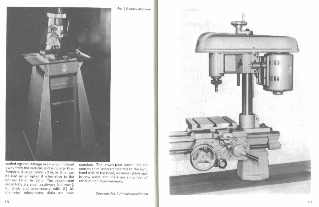
Fig. 6 Rodney ma chine
sealed against leakage even w hen incli ned away from the vertical, and is Quieter th an former ly. A large r table , 20 in. by 6 in., can be had as an optiona l al terna tive to the normal 16 in. by 5t in. The column and cros s tube are steel. as always, but now t in. thick and enormously st iff . 2t in. diameter m icrom eter d ials are now
standard. The down-feed w orm has for convenience been transferred to the right hand side of the head, a coa rser pitch rack is now used . and ther e are a number of oth er minor improvements.
Opposite, Fig. 7 Amolco attachment
18 19

Although colleges and commercial workshops wil l probably wish to use the all -over be lt guard, it may be debata ble if th e co st of this is justified fo r the so lit ary mature m ode l le r alo ne in hi s home workshop. An alternative belt gua rd wh ich covers the spi nd le pulley only and do es not impede belt chang ing so mu ch is ava ilable and is shown on the M ark II machine in Fig. 4 .
No do ubt the most importan t improvement is the (optional) provision of pow er feed fo r the long movement of the table. A small motor with a 4-step pul ley and enc lose d w orm reduction gear provides feed rates of .5 . .62 . .85 and 1.1 inches pe r mi nute.
A num ber of attachm ents similar in general concept , though much different in de ta il. to the old Abwood . have come on
Fig. 8 A mateo machine
<, Fig . 9 Menror machine, now superseded by th e
FB2 and Maximal attachment
the rn a rk e t in recent year s . Tew M achlnerv produce t he .Rodney' to su it th e Mvford M L7 and Super 7 lathes. and :hi s is marketed by Myfords. It is shown in Fig. 5 and the complete vertica l m iller ba sed on this attachment is th at shown in Fig. 6 .
Another attachment, t he 'A mo lco is supplied by N. M ole & Co. Ltd . and appears in Fig. 7 This has its own motor and attaches to t he top of the lath e bed also. It is made as a complete ma chi ne. snown in Fig. 8.
Fig. , t A stra machin e
2 1 20

Fig. 12 Twin machine
Elliot machine Equipment supp lied a continental mac hine, th e 'M entor' wh ich was available both in bench and floor mounted forms. The bench machine is shown in Fig. 9. They also have the 'M aximal' attach ment to suit the lat he of the same nam e, which f it s on the back of the lath e bed and has independen t motor drive (Fig, 10 ). This is also avai lable as a floor m achi ne, the FB2.
Ot her complete machin es inclu de the 'Astra' suppli ed by Scot Urquhart, w hich is really a horizont al miller w it h an ext ra ver tical spindle with it s own motor. Made in several sizes, the smal l one is show n in Fig. 11.
Twin Engin eering Co. introduced a bench machine il lus trated in Fig. 12 and also a floor mounted machi ne of sim ilar size but slig htly di fferent desi gn.
Fina lly the old established firm of Tom Senior Ltd . now produce their type E
mach ine w hich is f loor mounted and shown in Fig, 13.
So it will be seen that there are now many machines and attachme nt s which are of suit ab le dimensions for inclusion in t he l i m it ed sp a c e o f m o s t home w orkshop s. It would be useless to give any deta ils of prices in a book of this kin d, as such information would probably be incorrect by t he time the boo k was printed, and readers are therefor e recom mended to enquire of the various adve rt isers.
A summary of the leading particulars of all these machines etc. is given in Tab le 1 but again specificat ions are ame nded by makers as t ime goes by, and it can be no more tha n a general guide .
A brief w ord must be said about fore ign mac hin es. part icularly those coming from Far Eastern countries. I t wo uld appear there are several facto ries producing mac hine tool s and acce ssories. Some appear to be quite good, but others are definitely not good, and I do hav e personal experience of some of these. I have not had the chance to see one of the mill ing machines work ing, but those I have inspect ed in exh ibi t ions have some che ap and nasty feat ures, although the mai n items suc h as spind les, bear ings , and slideways m ay be excellent. Some of the machines are more suitable for com mercial factorie s th an home workshops but there are others of mo dest dimensions. To anyone contemplat ing buying one of these one can on ly suggest that a close inspect ion shou ld be made by a kno w ledgeab le engineer , and that a working demon str at ion should be requested, of th e actua l machine which is to be bought.
Fig. 10 Maximar ettscbrnent
22 23

TA
BL
E 1
Ma
ch
ine
or
Ma
ke
or
su
pp
lie
r a
tta
ch
me
nt
Tab
le s
ize
Sp
ind
le s
pe
ed
s
Sp
ind
le n
ose
C
om
me
nts
Wo
kin
g P
reci
sio
n W
est
bu
ry'
14 x
6
6 5
0.
11 2
0.
18 5
0.
2 M
Tp1
1l~
U
n-m
ac
hin
ed c
ast
ing
s M
one
ls C
o.
Ltd
. b
en
ch m
ach
ine
31 5
0
Myf
orn
th
read
o
nly
su
pp
lied
16
Do
ve
cot
Par
k ki
t of
pa
rts.
H
ead
sw
ive
ls.
Ab
srd
ou
r. F
ifp..
Sco
tla
nd
M o
del !
'ng
ine
eri
ng
'D
ora
Wp.
~tb
llry·
1
6 x
5 ~
3 4~
.90
. 1
88
2
Ml
plus
N
ow
su
pe
rse
de
d S
ervi
ces
. b
en
ch m
ach
ine
30
4.
79
0.
16
50
My
ford
th
read
by
Mk.
11
6. K
enn
et V
ale
, ki
t uf
pa
rts
Bro
ckw
ell
. D
o re
W e
stb
ury
1
6 x
5t
32
-18
80
2 M
T p
lus
Co
mp
lete
kit
of
pa
rts
. C
hes
lJou1
ielrt
. M
k.l
l (2
0 x
6
My
ford
th
read
A
ll m
ac
hin
ing
do n
e b
en
ch
ma
chi
ne
op
tio
n]
tha
t w
oul
d b
e d
iffi
cult
kit
of
pa
rts.
in
ho
me
wo
rksh
op
. H
ead
sw
ive
ls.
Tew
M a
Ch
iner
y lt
d.
'Ro
dn
ey
' F
or M
y/o
rd
Dri
ven
from
2
MT
plu
s R
igid
he
ad.
M a
no
r W
ork
s a
tta c
hm
en
t.
M L
7 a
nrt
la
the
spin
dle
Myf
ord
th
read
C
hur
ch S
I. 5
77
lat h
es.
Co
gg
cnh
oc
, 'R
od
ne
y p
lus'
1
5 x
4±
32
0,
45
0, 6
1 0
, 2
M T
p lu~
R
igid
he
ad.
No
rth
am
pto
n.
flo
or
rna
chin
c.
8 5
0.1
04
0,1
49
0,
Myf
ord
th
rea
d 2
19
0.
2 7
50
N.
Mu
le &
Cu
. Lt
d.
'Am
olc
o
For
My
furd
M
utu
r d
riv
e.
2 M
T p
lus
Rig
id h
ead
. 5
. Tu
lpil
s I
line
. i:t
1l8
<:l
lII
Ulf
l l.
& A
oxf
or d
4
spe
ed
s, 3
25
M
yfu
rd t
hre
ad
W
Hl t
",d
. HH
rtS
. ta
thes
. to
16
00
Oen
ch m
iller
. 15
x 6
3
25
-1 6
00
2 M
Tp
ill s
R
igid
hea
d.
Myf
ord
thre
ad
I AB
I F
1 (
co
nti
nu
ed
)
Ma
klllH
su
pp
lte
r
M ll
ch
in e
or
att
ach
m e
nt
Ta
ble
siz
t! S
p in
dle
spe
ed
s S
pin
dle
no
se
Co
mm
en
ts
Cllio
lt M
nc:
hlne
'M
en
tor
20
t x{
3 5
0 ,6
40
. 7 8
0.
2M
T
Sw
ive
lling
he
ad
.
F.'1
,Jip
men
t. rt
lHch
il1p.
14
50
U.L
C. H
nllH
H,
B.1
nch
and
ViC
lu ,i
HH
rl,
L on
don
. N
W 1
0 6
NY
flo
or.
F
S2
M a
xim
at
atta
ch m
e n
t nr
24
t x
6 1
20
-20
00
(six
) 2
MT
S
wiv
elli
ng h
aad
flo
or
ma
chin
e
Sco
t U
rqu
ha
rt L
td..
3
17. 3
/:~
,1 ,
Ear
lsfi
eld
Rn
.. 'A
str
a'
be
nch
anr
t 13
x 4~
62
0.9
00
. 12
00
. 1
8 5
0 2
MT
M
oto
rise
d h
ead
.
Ea
rlsf
ie ld
. fl
oo
r
l on
do
n S
W1
8 3
00
Il1
sch
in()
l';
Ho
r. w
ith
ver
t.
hea
d.
Tw
i ll
en!'!
.Co.
ee
lxto
n W
ay.
'Tw
in'
be
nc
h m
ac
hin
e
20
x 6
52
0. se
o.
16
50.2
88
0
2 M
T p
lus
Myf
ord
thre
ad
Rig
id h
ea
d.
Ho
lyw
ell
ind
. E
st.
W a
tfor
u. H
art
s.
and
flo
or
ma
chin
e.
20
x 6
3
80
, 6
40
. 1
100
. 1
90
0.
2M
T p
lus
Myf
ord
th
read
S
wiv
el h
ead
.
31 0
0
To
m S
en
ior.
Ltd
.,
A tl
as
W o
rks.
'Se
nio
r ty
pe
E'
lIo
or
ma
chin
e.
25
x 4
t 4
80.
9 5
0.
164
0, 2
76
0 2
MT
S
wiv
el
head
Hig
hto
wn
He
igh
ts.
Live
rse
dge
. W
est
Yor
ks.
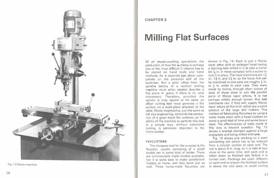
Fig. 13 Senior machine
CHAPTER 2
Milling Flat Surfaces
Of all m et al-w orking operations the production of true flat surfaces is perhaps one of the mo st di fficult if rel iance has to be placed on hand too ls and ha nd methods. for it depends jus t about compl et ely on the persona l sk i ll o f the workman. But a poi nt offse t from the spi nd le cent re of a ve rt ica l mill ing machine must when rotated describe a fla t plane in space i f there is no axia l movement. Therefore. provided the spind le is truly square to the tab le. an offset cutting tool must generate a flat surface on a w ork-piece att ached to the tabl e. Model engineering, just the same as full size eng ineering. demands the production of a great many flat surfaces. so the ability of the machine to perform th is task in a simple way, without expensive tooling , is extremely important to the home worker.
FlYC UTTERS The cheapest tool for the purpose is the
flycutter. usua ltv consist ing of a small toolbit set in some kind of holder. There are commercially made holders avai lable. but i t is quite easy to make satisfactory holders at home. and they serve jus t as well Three home-made flycutters are
shown in Fig. 14. Each is jus t a Morse tape r arbo r w ith an enlarged head having a slanti ng hole dr illed in i t to take a cutt er bit (t in. in these samples) with a screw to lock i t in place. The head d iameters are 1t in.. q . in. and 2t in. so th e face s that can be mac hined at one pass are roughly tin. to 1- in . wider in each case. They w ere made by boring through short pieces of steel of these sizes to suit the parallel parts of Morse taper arbor s. It is not perhap s widely enough known that tool merchants can. if th ey will , supply M orse taper arbors of this kind. w hich are a stock product of the large dri ll makers. This method of fabricat ing flycutt ers by using a ready made arbor wi th a head Loct ited on saves a good deal of time and some heavy st eel. The effectiveness of to ols made in this way is beyond question . Fig. 15 shows a bracket clamp ed aga inst a large angleplate and being milled with one.
Fig. 16 shows one working on a steel connecting rod which has to be reduced from a circular section at each end. The rod is about 9 in. lon g. so it is held in two vices at the same time. and each end is taken down to fin ished size before it is tumed over. Packings are used . different at each end to ensure the finished -surface is above the vice jaws, to avoid cutting
27 26

Fig. ' 4 Set of three flycutters
int o them , and the se pack ings en sure the Ow ning two vi ces alike m ay at fi rst rod is at the right att itu de fo r keep ing t he tho ugh t see m somethi ng of a luxury , bu t mi l led surfaces para l le l to the ax is , as so on as lon g art icles have to be deal t
Fig. '5 Fly cu tt ing a bracket
Fig . 16 Flycutting connecting rod ends
with the benefit s are at once apparen t. reduced to a tapered sec tio n to cu t up into Ano ther flycutt ing operation is shown wedge blo cks for connec t in g ro ds or the
in Fig. 17 where a steel bar is be ing type in th e previous picture. These wedge
Fig. 17 Flycutting tapered bar material
29 28
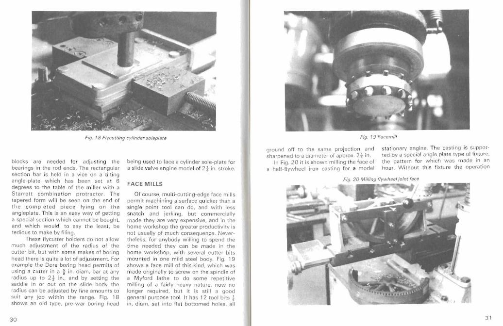
Fig. 18 Flycu tt ing cylinder soleplate
bloc ks are needed for adjust ing the beari ngs in the rod ends. The rec tangular sect ion bar is held in a vice on a tilti n ang le-p late which has been set at 6 degrees to the table of th e mil ler with a St ar rett com bin atio n p ro trac to r. Th e tapered form w il l be seen on th e end of t he co m p l et ed piec e ly in g on th e anglep late. This is an easy w ay of getti ng a speci al sect ion which cannot be bought, and wh ich would, to say the least. be tedious to make by fi ling.
These flycutter holders do not allo w much adjustme nt of the radius of the cutte r bi t, but w it h some ma kes of boring head there is quite a lot of adjustme nt . For exam ple the Dare boring head permits of usi ng a cutt er in a fi n, dia m. ba r at any rad ius up to 2t in., and by sett ing the saddle in or out on the slide body the radius can be adjusted by fine amo unts to suit any job w ithin the range. Fig. 18 shows an old type, pre-war bo ring head
being used to face a cy linder sole-p late fo r a slide valve engine model of 2t in. stroke.
FACE MILLS
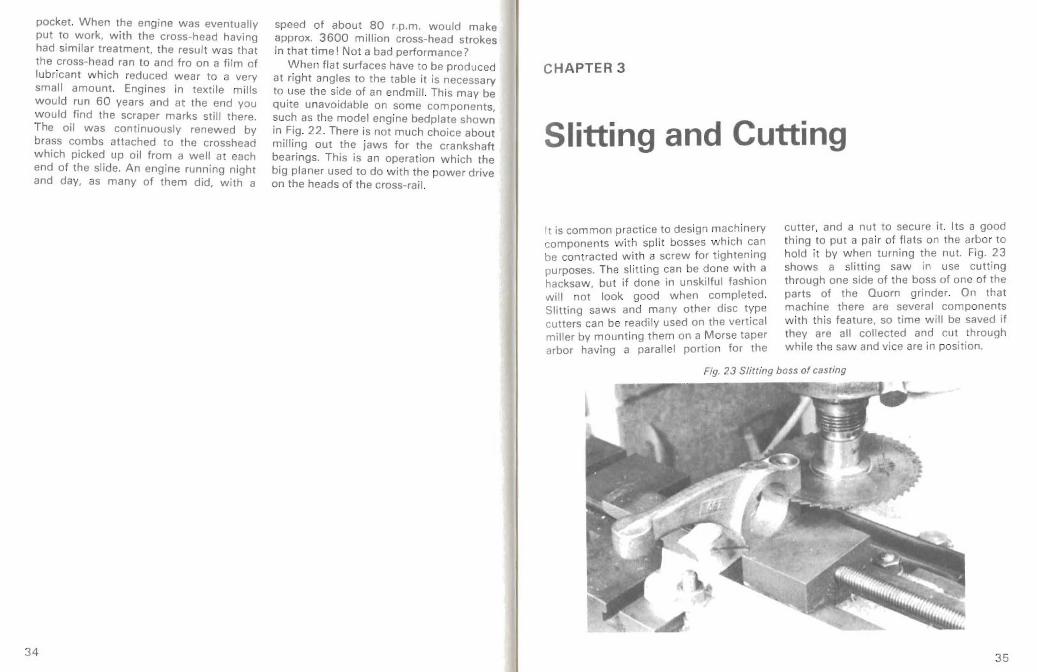
Of cou rse, mu lt i-cutt ing-edge face mi lls perm it mac hining a surface quicke r tha n a single point tool can do, and with less snatch and jerki ng, but com mercia lly made they are very expens ive , and in the home workshop th e greate r productivity is not usually of much conseq uence. Nevertheless, for anybod y w ill ing to spend the time needed they can be made in the home w orkshop , w ith several cutte r bi ts mounted in one mild steel body . Fig. 19 show s a face m il l of this kind , which was made originally to screw on the spind le of a Myford lathe to do some repeti tive mi lling of a fa irly heavy nature, now no longer required, but it is sti ll a good general pu rpose too l. It has 12 tool bits :lin. diam . set into flat bottomed holes, all
Fig. 19 Facemill
stationary engi ne. The cast ing is suppor
sharpened to a diameter of approx. 2t in. ted by a spec ial angle plate typ e of fixture,
In Fig. 20 it is shown mill ing the face of
ground off to th e same pro jec tio n. and
the patte rn for w hich w as made in an hour. W ithout this f ixture the ope rat ion a half -flywhee l iron cast ing for a model
31 30

Fig . 2 ' Milling crosshead slide
would be some w ha t diff ic u lt. If th cas ting w as held in a vice on the table the point of cutting would be a long way from the ho ld ing point. and mo vem en t of the cast ing under the pressu re of cutti ng wou ld be no t easy to prevent. Vibratio n and chat ter w ou ld be more likely. It very often happens that the only wa y to ge t a satis fac to ry jo b is to make som e equip ment specia lly for it. This is no t usuall y wasteful. especia lly jf a duplicate component is ever requi red. bu t the equipme nt is usually found adaptable for some other job later. Doing metal cutting by 'knifeand-fork' methods can Soon lead to disaster. The other half of the w heel cast ing. with the cast- in teeth for the barring 'rack', can be seen in the bott om half of the picture. The w heel is 9f in. diameter and has 96 teet h.
Broad f lat surfaces can be. and sometimes have to be, produced by Success ive
paralle l passes w it h an end mi ll m uch narrower th an the face requ ired . Apar t from taking mor e time than a too l w ith a wide sweep. m inute ridges tend to be left w here the passes overlap. and these m ay have to be removed lat er by fil ing or scrapin g. So w hile this method is feasible the f lyc utter or bo ring head is be tte r w here there is room to use it, and the cutter bits are cheape r than endm ill s and easily sharpened like any lathe too l.
However. an example of work wh ere a sma ll Cutte r and successive passes mus t be used is shown in Fig. 2 1 w here a flat bedplat e slide for the crosshead on a mode l sta t ionary engi ne is be ing milled. The surface being cut is in a recess tin. deep and the Corners cannot be dea lt w it h by a tool cutt ing the full Width. as the radius left wou ld be too great. Not e the stop bar bo lted to the table. Accura tely squared w ith the table it provides not only
correc t location for the casti ng (wh ich was follo wed by others) but also insurance against slipp ing .
In the fu ll sized engi nes these slides we re always planed, and every enginebuild ing shop had planers for thi s kind of wo rk. In the one wh ere I w ork ed there we re several of diHere nt sizes. and the arqest, built by Joshua Buckton of Leeds. auld plane any cast ing up to 20 ft. long.
12 ft. wide and 12 ft. high . It w as said at tha t time to be the largest in Yorksh ire . and certainly it often did cast ings for other firms. Cutti ng could be done in both directions of the tab le travel at equal speeds. or in one direction with a qui ck return the other wa y. Each of the four too lheads had pow er operat ion independent of tab le movement, so that cross-p laning cou ld be done through bearing recesses . etc. One of the pictures show s this operation on a model being do ne by mill ing. Each
head could also be swive lled so that ang ula r faces could be planed also .
After the planing of crosshead slides they we re tackled by the fillers and scraped to a portable surf ace plate. This was coa ted sparing ly with a mixture of lamp black and oil. slid to and fro on the slide . li ft ed off. and then all the black marks scraped away. The surfa ce plate w as then put on aga in and a fresh lot of marks mad e. w hich in turn w ere scraped away. This work went on for many hours, indeed on a big slide tw o men cou ld spend two or th ree days. For such work the surface plate wo uld be so large th at two men cou ld not lift it withou t the use of the shop crane. Eventually afte r a long t ime the finish obta ined wou ld be rega rded as acceptab le. It then consisted of a very large number of extremely shal low depressions betw een the marks . and each of these proved to be an oi l
Fig . 22 Milling bearing jaws in bedp la te
33
32
pocket. When the engine was eventually pu t to work, with the cross-head having had similar treatment. the resu lt was that the cross -head ran to and fro on a film of lubr ican t which reduced wea r to a very small amount. Engines in textile mil ls would run 60 years and at the end you would find the scraper marks still there . The oil was continuously renewed by brass combs attached to the crosshead which picked up oil from a well at each end of the slide . An eng ine running night and day. as many of them did . with a
speed of about 80 r.p.m. would make approx. 3600 million cross-head strokes in that time! No t a bad performance?
When flat surfaces have to be produced at rig ht ang les to the table it is necessary to use the side of an endm ill . Th is may be quite unavoidable on some components, such as the model eng ine bedplate shown in Fig. 22. There is not much choice about milling out the jaws for the crankshaft bearings. This is an operation wh ich the big planer used to do with the power drive on the heads of the cross -rail.
CH APT ER 3
Slitting and Cutting
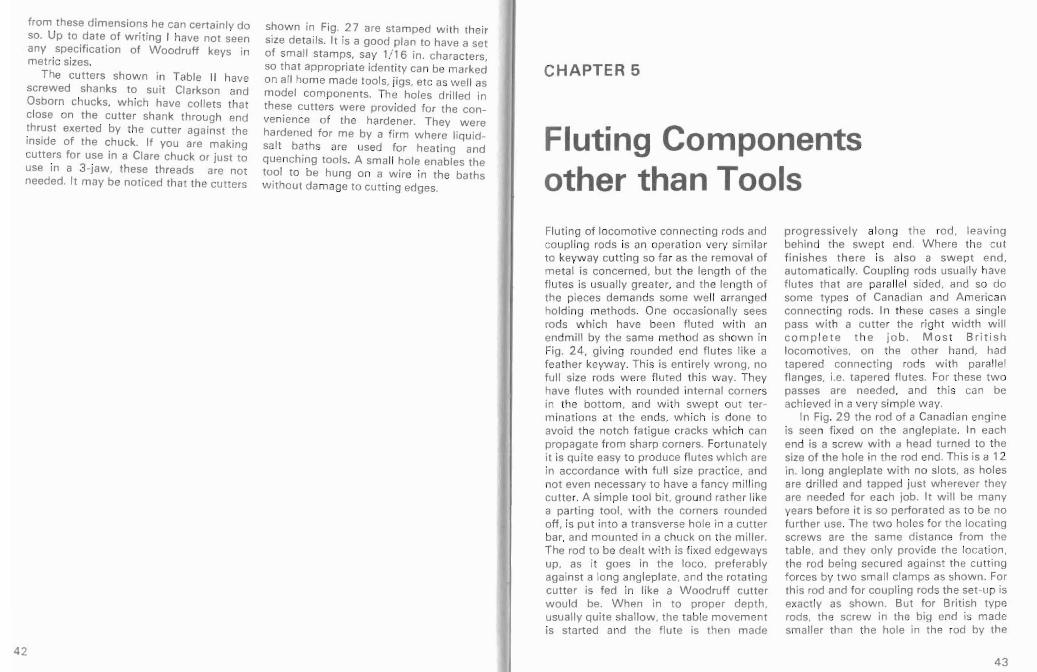
It is common practice to des ign mac hinery components with spli t bosses w hich can be contracted with a screw for tightening purposes. The slitting can be do ne with a hacksaw. bu t if done in unskilful fashion will not look good when completed . Slitting saws and many other disc type cutters can be readi ly used on the vertical miller by mounting them on a Mo rse taper arbor having a parallel portion for the
cutter, and a nut to secure it . Its a good thing to put a pair of flats on the arbo r to hold it by when turning the nut. Fig. 23 shows a slitting saw in use cutti ng through one side of the boss of one of the parts of the Quorn grinder. On that machine there are several components w ith this feature, so time will be saved if they are all col lected and cut th rough while the saw and vice are in position.
Fig. 23 Slitting boss of casting
35 34

M any other jobs of simila r nature w il l come to mind, such as engi ne eccent ric sheaves, and especia lly eccent ric straps . wh ich can be cast in one piece and then cut thr oug h, leaving two surfaces that need only a to uch with a fi le to rem ov e
burrs to enable them at once to be bolted together. Not on ly are castings involved but also parts made from bar material. Ma rin e type connecting rod ends are an example. and this method can also be used for producing bearings in halves.
CHAPT ER 4
Keyway Cutting
Keys and keyways are a very commo n feature of machi nery and naturally of models too. The common round-e nded keyway. for a ' feather' key . is easily produced on a parallel shaft by holding the shaft in the vice and using a small end mill , or two -f lute 'slot-drill' . Fig. 24 show s the setup for this ope ration.
Various parts of car and motor cycl e
engines. gearboxes, and other machinery components in the past have had whee ls mount ed on tapered shafts wi th the keyways foll owing the slope of the taper. Modellin g one of these wou ld involve fo llo wi ng the same proce du re. One way in wh ich this can be done is shown in Fig. 2 5. The vice holdi ng the shaft is set on a tilting angleplate so th at the top of the
Fig. 24 M illing Ieether keywa y
37 36

Fig. 25 Milling fe ather ke yway on tap ered shal t
tapered pa rt comes pa ralle l w it h the m achine tab le. The shaft show n in the pictu re is a sim ple on e and quite short . and could have been just t ilted in the vice in a set-up like t hat of Fig. 24. But a long shaft might well fo ul th e table at it s low er end so the elevation which the anglepl ate gi ves could in such a case prove essent ial.
Sma ll endm ills are rather f rail to ols at best and liable to easy breakage . The di sc ty pe cutter is more rob ust and a collecti on of these acquired either as the need fo r one crops up , or bought cheaply seco ndhand, is w ort h while . Of course th e disc cu tte r canno t always go close to a shou lder on the shaft , and copying a pro totype may in some cases rule it out . For th e w ork do ne in t he hom e workshop there is no need to insist on the relatively expe nsive side -and-face cutters, (those with teet h on the faces as w ell as th e pe riphery ) because the sli tting saw , w ith teeth only on the periphery, w il l do qu ite wel l. These are m ade in a very great variety of
thicknesses , and are always comi ng on the surp lus m arket at low prices. One of t hese is shown in Fig. 2 6 m illi ng an ord inary sunken keyw ay, th e shaf t bei ng held in a vice wi th enough overhang to avoid t he cutter tou ching the vice.
WOODRUFF KEYS
The Woodruff key is on e w ide ly used in ind ustry. This is in effect a slic e off a round ba r, cut in ha lf and set in to the shaft in a recess m ade by a sma ll d iam eter slitting saw . Th is is rath er an oversimplif ied des cr iption, but it wi ll serve we ll enoug h as an introduct ion to the W oodruff key for thos e in ho me w o rks h op s w i t hou t indust r ia l ex perience. Seriou sly . th e W ood ruff key. w hich I think was of A m erican or ig in, has som e very real advan tag es for th e m ass pr oducti on industry, and some of thes e are of just as gr eat impo rt ance in the home workshop and the fi eld of light engineering.
Fig. 2 6 M illing keyway w ith sli tt ing saw
For a sta rt the key itself can be parted ac curacy f ro m t he b ri ght ba r. The off fro m a piece of round mi ld steel or thi ckness needs careful contro l, but if it silver steel. So its d iam eter is sett led w ith com es off a b it too t hick i t can be rubbed
Fig. 27 Set 01four W oodruff keyw ay cutters
38 3 9

teet h can be cu t in two ope rations using an ordinary end mi ll ; the re is no need for angu lar cu tters. as t he d iagra m on the opposite page indicates. The num ber of teeth is no t importa nt, but six is a co nven ient numb er for small cutters . It is possible to file the teeth if you do not have access to a div iding head. as the spacing is not at all critical , but it's a little more difficult . Fig. 27 shows a batch of cutters made to the sizes in Table II and Fig. 28 shows a keyway being cut . There seems to be no place where sizes of Woodruff keys and cutters are disp layed for model engi neers . Machinery 's Handbook giv es sizes wh ich are used in industry. but the sheer range of sizes is i tself confusing, and of cou rse t he tables are libe rally sprin kled wit h to lerances that model lers cou ld neither follow no r wa nt . I have therefore picked ou t a few sizes wh ich I think wi ll serve ou r pu rpo se. and as we don 't have to provide interchangeability in our products, if anybody w ant s to depa rt a bit
41
Fig. 28 Milling Woodruff keyw ay
the diametra l line of the shaft. the n th e cutt er is fed in by a predetermined amount.
The resulting keyw ay is deep enough to give the key a good ho ld, so that i t cannot roll over, and yet the shaft is no t unduly wea kened. Norm ally th e top of the key is just clear of the keyway in the wheel or lever wh ich is being secu red , its purpose bei ng to provide eit her tor qu e or angular locat ion, and some mea ns such as a grub screw may have to be used to preve nt endwise movement.
W oodruff cutters are not very cheap, but they can easily be made in the home workshop, from silver steel. The process is really qu ite simple. A blank can be turned, mak ing a shank to sui t some sta nda rd collet. then with the shank held in the colle t the working part of the cutte r can be turned to it s diameter, and th ickness. The sides sho uld be very sligh tly undercut by setting a kni fetool a little off square. Using a sim ple un-geared dividi ng head the
key is ma de, with an integral shank of preferably some sta nda rd di ame ter w hich can be run true in a collet on the mi ller. So the shape of the keyw ay pro fi le - and its w idt h - is settled by t he cutter form. The cutti ng par t of the cutter is set in line w ith
2
TABLE II
3 F~ x20 B.S.F. FOR
CLARKSON Be. OSBORN CHUCKS.
WOODRUFF KEY S & KE.YWAYS CUTTERS A B C D E F G ~ I
'10 9 '030 44 -(6 '073 '037 '10 0 ~6 .% 140 '/ 0 4 '03 7 '/04 '037.6 3-'8 %2 '172 '/23 '053 -/ 29 '045 ~ ~ 2 -203 '155 '053 -1 87 '060 2
G~
down on a flat file . It needs to be cu t in two on a line w hich is nearly a dia me ter, but the cut edge can readily be filed to br ing it to f ina l shape . The keyw ay is made by a simple cutter like a slitt ing saw, of the same diameter as the bar from wh ich the
40
from these dimensions he can certai nly do so. Up to date of w riting I have not seen any spec ifica tion of W oodruff keys in met ric sizes.
The cutters shown in Table II have screwed shanks to suit Clarkson and Osbo rn chucks, wh ich have colle ts that close on the cutter shan k through end th rust exerted by the cutter agai nst the inside of the chuck. If you are making cutters for use in a Clare chuck or just to use in a 3 -jaw . these thr eads are not needed. It may be noticed that the cutters
shown in Fig. 27 are stamped w ith thei r size de tai ls. It is a goo d plan to have a set of small stamps. say 1/1 6 in. characters. so that appropriate identity can be marked on all hom e made tools. jigs. etc as we ll as model compo nents. The holes dr il led in these cu tte rs were provided fo r the convenien ce of the hardener . They were harde ned for me by a f irm where liquid salt bath s are used fo r heat ing and quenching tools. A sma ll hole enables the tool to be hung on a w ire in the bat hs w ithout damage to cutt ing edg es.
CH APTER 5
Fluting Components other than Tools Fluti ng of locomotive con necti ng rods and coupli ng rods is an operation very sim ilar to keyway cu tting so fa r as the removal of me ta l is concerned. bu t the length of the flutes is usually greater, and the lengt h of the pieces deman ds som e w ell arrange ho lding methods. One occasiona lly sees rods which have been f luted w ith an endmi ll by the same metho d as show n in Fig. 24. giving rou nded end flute s like a feath er keyway. Thi s is ent irely wrong . no full size rods w ere fluted this w ay. They have flutes w ith rounded internal corne rs in the bot tom. and wi th swept out t erminatio ns at the ends, which is done to avo id the notch fatigue cracks w hich can propagate from sharp corners. Fortunately it is qui te easy to produce flutes which are in accordance with full size pract ice. and not even necessary to have a fancy m ill ing cutler. A simp le tool bit , gro und rather like a partin g too l. wi th the corners rounded off. is put into a transverse ho le in a cu tler bar, and mounted in a chuck on the mil ler. The rod to be dealt with is fixed edgeways up , as it goes in the loco. prefe rably against a long ang leplate . and the rotat ing cutle r is fed in like a W ood ruff cutler wou ld be. Wh en in to proper depth. usually quite shallow, the table movement is started and the f lute is then made
p rogressive ly along th e rod, leaving behind the swe pt end . Where the cut fini sh es there is also a swept end, automatica lly. Coup ling rods usually have flutes that are parallel sided, and so do some types of Canadian and American con nec ting rod s. In these cases a single pass with a cutle r the right w idt h w ill c om p lete t h e jo b. Mo st Br i t i sh locomotives. on the ot her hand , had tape red con nec ting rods wi th parallel f langes . l.e. tapered flutes. For these tw o passes are needed. and th is can be achieved in a very simpl e w ay.
In Fig. 2 9 the rod of a Canadi an engine is seen fixed on the angleplate. In each end is a screw with a head tu rned to the size of the ho le in the rod end. This is a 12 in. long angl eplate wi th no slots. as hol es are drilled and tappe d just w herever they are needed for each job. It w ill be many years before i t is so perforated as to be no fur ther use. The two holes for the locating screws are the same distance from the table. and they only provide the locati on . the rod being secured against the cu tting forc es by two sma ll clamps as shown. For this rod and for coupling rods the set -up is exac tly as shown. But for British type rods . the screw in the big end is made smaller than the hole in the rod by the
42 43

Fig. 29 Fluting locomotive conn ec ting rod
amou nt of the taper (at the hole centres) and for the f irst operation the rod can be allowed to dro p down on the screw whi le the fi rst cut is taken. Then for the second cut the rod is lift ed up as far as the screw w ill let i t go . and re-c tarnp ed. and a second cut taken, The rod w ill now finish w ith a taper flu te and two parallel flanges.
Th is f luti ng is a very simple ope rat ion . The angleplate is extreme ly rigid. The mach ine in the picture is happily provided wi th a t in. w ide keyw ay along the centre of the table. only t in. deep . but a i- in.
square bar can be dropped into it. That enables fixtures to be instantly lined up w ith th e tab le movemen t . inc lud ing dividing heads as we ll as ang lep lates. The thrust of the cutte r in this example tends to move the ang leplate awa y from the bar . but it is secured w ith tw o good bo lts in t he t ab le slots. no t v isi b le i n t he photograph. It should not be forgott en that locomotive rods w hich are flu ted at all must be done on both sides. but wi th a set- up li ke this the job is so simp le it w ou ld be a pity not to have it right.
CHAPTER 6
Boring
It is not uncommon to have bor e holes in components w hic h are much too large to sw ing around in the lathes that are found in mo st home workshops. But there is no need in many cases to resort to hand too ls. even for holes w here great accuracy is not needed. The vert ical mil ler can be used for boring (w ith a trepanning tool in a bo ring head) such th ings as fire-hole doors in bo iler plates. bosses on castings such as long levers. and many other ob jec ts. In order to rnot ori se a shaper I had to bore a hole through t in. of cast iron to mo unt a worm reduction gearbox . and this had to be a true round hole. It was done by fix ing the cast ing (15 in. long in one direct ion from the centre of the
ho le) on the mil ler tabl e and using a cutt er in a boring head. W ith the w orm- actuat ed dow n feed. and the bot tom speed of the Dare-Westbury machine. 34t rpm. an excellen t hole wa s obtained four inches diame ter. W ithout these facil i t ies the work wou ld have been sent out to some engineering firm. The ampler space on the tables of mil ling machines. compared w ith w hat one can get on a lathe saddl e w ith an angle plate . makes the miller invaluable for w ork of this kind and of cour se by do ing externa l tu rnin g w ith a boring head one can dea l w ith male registers as we ll as hol es. This is a simp le operat ion too; one just turns the cutt ing tool inw ard instead of outw ard.
44 45
47
.J. /6
-+--II-- -005
.l +
a6+
,..,38
posit ion by using the table cross-screw to provide the amount off th e main line. W hen all the ho les are fin ished the beam can be tu rned over and the bosses mill ed on the other side .
Th e beam engine cast ing is just one example of how t his sort of task can be handled. Fig. 30 is a draw ing of a component of th e t rip gea r of a model steam engine. and the holes w hich have to be drilled are in posi t ion s w hich w ou ld not be easily att ained by the co m mon markingout and centr e punching proces s. Fig. 31 shows one of th e finishe d pieces w it h one only part-ma de, to show the me thod adopted. One inch diameter bar wa s used . as that gives th e outside profile needed. Set true in th e fo ur- jaw chuck it was bore d 9/ 16 in., the n set out of true by .047 in. and the ho le re-bored to the same sett ing . Next it was set well off centre to dril l the No. 38 drill hole. Th e correct setting was established by measurements
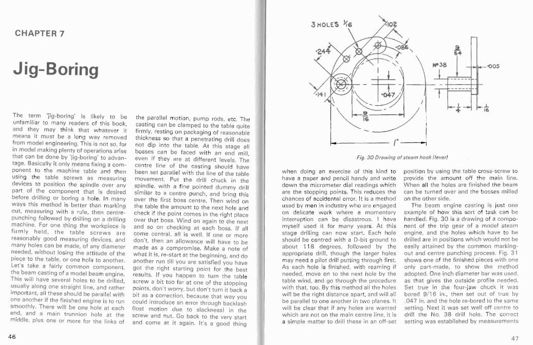
Fig. 3 0 Drawing of stea m hook (lever)
r - I
. ~--" =::--
...,."
t - I
\ I ~ ~: ~ ~: 7
w hen do ing an exercise of this kind to have a paper and pencil handy and w rite dow n the micrometer dial readings w hich are th e stopp ing points. This reduces the chances of acciden tal error. It is a method used by men in industry w ho are engaged on delicate w ork w here a momentary in terru pti on ca n be disastrou s. I have my self used it for many year s. A t th is stag e drillin g can now sta rt . Each hol e should be centred w it h a D-bi l groun d to about 1 18 degrees, foll ow ed by the app ropriate dri ll. thoug h th e larger holes may need a pilot dr ill put t ing through first . As each hole is finished. w ith reami ng if needed, move on to the next hole by the table wi nd. and go th rough the procedu re with th at. too. By this meth od all the holes w il l be the right distance apar t , and w ill all be paralle l to one another in tw o plane s. It w ill be clear th at if any holes are wanted which are not on the main centre line, it is a simp le mat ter to drill these in an off-set
the parall el motion, pump rods, etc. The casti ng can be clamped to the table qu i te firmly, rest ing on packaging of reason able thic kness so that a penetrati ng drill do es not dip in to the table. A t th is stage all bosses can be faced w ith an end mill , even if they are at differen t levels. The centre lin e of the cast ing should have been set paralle l w ith the line of the table movement . Put the drill chuck in the spind le. w ith a f ine pointed du mmy dri ll sim ilar to a ce ntre punch. and br ing this over the first boss cen tre . Then wind on th e table the amou nt to t he next hole and check if the point com es in the right place over that boss. W ind on again to th e next and so on check ing at each boss. If all come cen tra l. all is wel l. If one or mo re don't. then an allow ance w il l have to be made as a co mprom ise. Ma ke a note of wha t i t is. re-start at the beginning, and do another run t ill you are satisf ied you have got t he rig ht starti ng point for the best results. If you happen to tu rn the ta ble screw a bi t too far at one of the stopping points, do n't worry, but do n' t turn it back a bit as a correct ion , because th at way you cou ld introduce an error thro ug h back lash (lost motion due to slackness) in the screw and nut. Go back to the very start and come at it again. It's a good thing
CHAPTER 7
J ig-Boring
The ter m 'j ig-boring' is likely to be unfa miliar to many readers of this boo k, and they may thi nk that w hateve r it mean s it must be a long way removed from model engineering. This is no t so, for in model making plenty of operations arise th at can be don e by 'jig-boring ' to adva ntage. Basicall y it only means fixi ng a com ponen t to t he mach ine tab le and th en using the tab le screw s as measuring dev ices to posit ion the spindle over any part of th e com ponen t that is desired before dr illing or boring a hole. In many ways t his meth od is better than marking out, measu ring wi t h a rule, then centrepu nch ing fo llowed by drill ing on a drilling machine. For one thing th e wo rkp iece is f i rm ly held , t he t ab le screws are reasonably goo d measuri ng devices, and man y ho les can be made, of any diameter needed. without losing the att i tude of the piece to the table, or one hole to another. Let's take a fairly com mon componen t, the beam cast ing of a model beam eng ine . This will have severa l holes to be dri lled , usual ly along one straight line. and rather importan t. all these shou ld be parallel wi th one another if the finished engi ne is to run smoothly. There will be one ho le at each end , and a main trunnion ho le at the middle, plus one or more for the links of
46
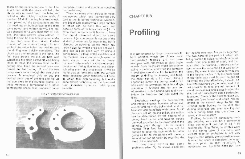
taken off the outside surface of the 1 in. bri ght bar. With the piece st il l held. the chuck w as removed from the lath e and bolted on the m illing mach ine table. A number 3 8 dr ill . running in a tru e chuck. then 'picked up' the exist ing hol e and the dial readin gs on both screws of the table w ere noted {and w ri tten down !' The drill was chan ged for a very short st iff 1/ 16 in. drill . the table screw s were ro tated . to bri ng the first 1/16 in. hol e pos it ion under it and tha t hole then dr illed. Further rota tion of th e screws brought in turn each of the other holes into pos it ion and the drill ing wa s quickly completed. The chuck was then returned to the lathe. The fi rst boss around the No. 38 hole was turned and the piece parted off. care being taken to leave the shallow boss on the part ing side. Then the second bos s w as turned. another part ing off . and the two components w ere th rough that part of the process. It remained only to cut the desired piece out of the ring and file up the two ends to the rounded profile. By these methods a com ponent of a rather compli cated shape w as produced und er
complete control and exactly as specifi ed on the drawing.
There are many other art ic les in model engi neering wh ich lend themselves very w ell to the jig-boring technique. Locomot ive boiler tube plates w ith a large num ber of holes can be do ne this w ay. and because some of the holes may be t in. or even mo re in di ameter it is vita l to have th e m et al c lam ped do w n to avoid personal injury. as copper is not one of the kindest of materials for machining. But if clampe d on packings on the miller. any large holes for w hich dr ills are not available can st ill be dealt w ith by using a boring head. If a large drill is available. and th e machine has a low enough speed to avoid chatter. there w ill be no 'threecornered' holes made to cause embarrassment w hen f itting flue tubes and silversoldering them at a later stage. It w ill be fo und that as familiari ty w ith the vert ical mi ller develops. other exam ples wi ll arise in w hich this high-soun di ng but really qui te simple technique can fr om ind ust rial p ract ice. benefits.
be bo rrowed w i th great
Fig. 3 1 Photograph of steam hook
•••
CHAPTER 8
Profiling
It is not unusual for large components to have po rti ons w hich are ci rcular arcs , Loco m o t ive f r am es ar e co m mo n examples. w it h cut-aw ays to clear bogie wheels. Such pieces are m uch too large to sw ing in the lathe. and wh ile the bandsaw if available can do a lot to relieve the tedium of drilling. hacksaw ing and f iling. the miller can do a lot more. Using a trepanning cutt er in a boring head it can take aw ay the unwant ed metal in a single operat ion to finished size on any arc. A lte rnatively w it h a bor ing typ e tool it can follow the bandsaw and just avoid th e fi ling.
Smokebox cast ings for locomotives and tract ion eng ines. how ever, oft en have circular arcs to fit the boiler shell. and the bandsaw can be nohelp with these. But if they are set up on th e mi ller. the radius can be deter mined by the sett ing of a bo ring head cutt er. and trave rse across the wo rk provided by th e downfeed of the spindl e. eve n though th is is usuall y manual. That feed lengt h may not be enough to cover the face width, but aft er going as far as the spindle w il l move. a second cut can be taken by resetting th e head of the mach ine .
I n m ac h i nery de t a i l s t h e same problems arise. Fig. 32 shows a pad bo lt
for locking tw o machine parts together. The two parts of the pad bolt w hich are being pro fil ed to suit a rou nd column we re made fro m one piece of steel. and cut apart afte r th e profiling. A gro ove can be seen w here the separating cut wa s to be taken. The cutt er in the bor ing bar w as set to the fini shed radius. Only the cross-feed of the table was used (to put the cut on bi t by bit) th e other slide being locked. The tool w as t raversed by the down feed. It is no t possible to tak e the full am ount of metal removal in a single pass in a job like this, but w ith successive cuts a perfect job is assured. Sim ilarly the holes for such pad bol ts are 'part holes' and could not be dril led in the second stage to full size w ithout gui de bus hes for the dril l. But drill ing undersize and then open ing out with a bo ring head gets there just t he same, a bit less qu ickly.
Prof iling locomotive connec ting rods and coupling rods can be a somew hat t iring operat ion if one has to do it by sawi ng and filing. Trying to do this w ork on the bo ring table of the lathe wi th vert ica l slide or angleplate is not very happy eith er. Usually the cross-slide travel is mu ch too short to comp lete the length i n one pass. so that re - sett ing is necessary. and the lathe does not have
48 49

the in-feed faci lities needed. Gene rally with a vertical slide the poi nt at w hich cutt ing is be ing done at the ends of a long rod is a very long w ay from th e place where the slide is secured, so that apart from 'spring' of th e piece there is danger of slipp ing taking pla ce with dis astr ous results. Com pare such attempts w ith the
Fig. 32 Profiling pad bolt
Fig. 33 Profiling coupling rods
set-up sho w n in Fig . 33. w here a pair of coup ling rods . w ith 'chucking pieces' o f extra me ta l at each end , are clamp ed on packings in a safe and rigid set-up. Generally th e di amet er of end m ill used can be arranged to give the right radi us where the body of the rod jo ins the boss es.
50 51
CHAPTER 9
End-Rounding
In model work, as in ful l sized machinery, many comp onents such as crank webs, connect ing and cou pling rods , machine links, etc. have to have rounded end s. These can be produced by fili ng, and the use of hardenerd steel collars and roller s for gu ides has oft en been recommended in Model Engineer to help the not-sa-good f ile r to achieve a good appe arance. Even wi th these, this kind of filing demands a skill wh ich many modellers jus t do not have (and wi ll never acqu ire, for wa nt of pract ice, if nothing else) so for that reason alone it is not a good method. But it is also rathe r seve re on fi les, w hich are now qui te expensive too ls, and unlikely ever to get cheaper.
So w here there is a vert ica l miller available, w hy not do the job th e rig ht w ay. as it wou ld be done in com mercia l engineering ? It means invest ing in a rotary tabl e. but these can be bought in kit form as we ll as comp le te ready for use. and if mach ined and assembled by the home worker himself. are not terribly expensive. Presum ing that the component has a round hole at one end . a plug is needed in the table so as to locate by that hole. I have a sm all ro tary table w ith a t W hit. ho le in the cent re and have a number of plugs of standard sizes to fi t tha t. Bu t
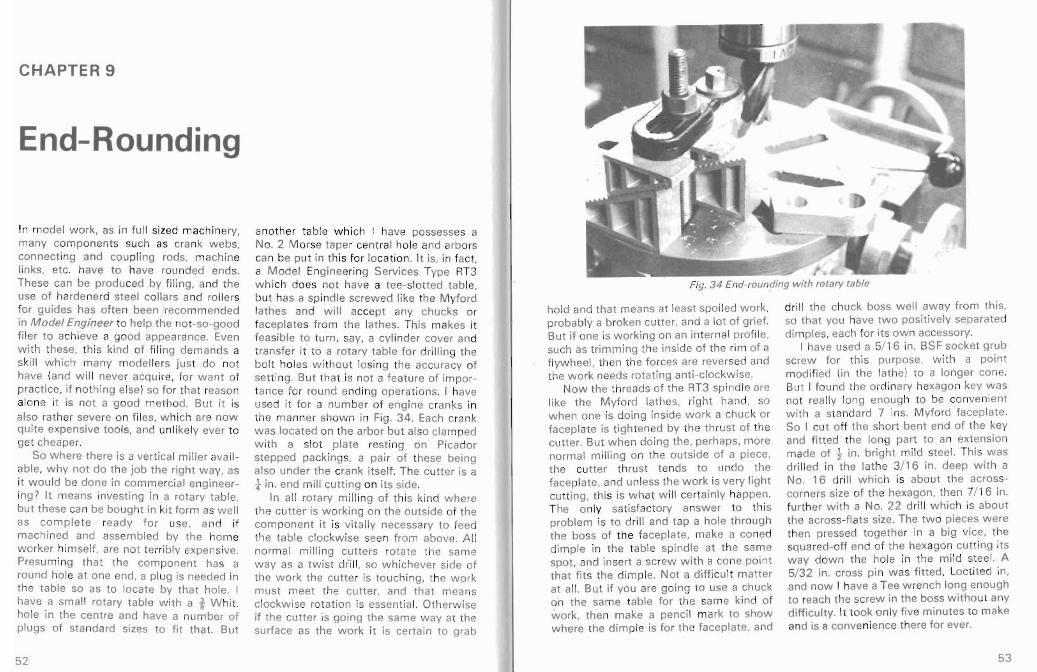
another table wh ich I have poss esses a No. 2 M orse tape r centra l hole and arbor s can be put in this for locat ion. It is. in fact , a Model Engineering Services Type RT3 wh ich does not have a tee-slott ed table, but has a spindle screwed lik e the Myford lathes and will accept any chucks or faceplates from the lathes. This makes it feasible to turn , say, a cy linder cover and transfe r it to a rotary tab le fo r dri l ling the bo lt hol es wi thout losing the accur acy of setti ng , Bu t that is not a featu re of importance for round ending operat ions. I have used it for a numb er of engi ne cranks in the manner show n in Fig. 34. Each crank was located on the arbor but also cla mped w ith a slot plate resti ng on Picado r stepped packings, a pair of these being also unde r the crank itself. The cutter is a t in. end mill cutt ing on its side .
In all ro tary mil ling of this kin d w here the cutter is work ing on the outs ide of the component it is vitally necessary to feed the table clockwise seen from abov e. All no rma l milling cu tt ers rot ate the same w ay as a twist dfl ll, so wh ichever side of the work the cutte r is touching, the w ork mu st meet the cut te r. and that means clockwise rotation is essenti al. Oth erwise if the cutter is goi ng the same w ay at the surface as the work i t is certa in to grab
hold and tha t means at least spo iled work. probably a broken cutt er. and a lot of grief. But if one is w orki ng on an intern al profile, such as trimming the ins ide of the rim of a flywh eel. then the forces are reversed and the w ork needs rotat ing ant i-clockwise.
Now the threads of th e RT3 spi nd le are like the Myford lathes. righ t hand , so wh en one is do ing inside work a chuck or faceplate is t ight ened by the thrust of th e cutter. But w hen do ing the. perhaps, more norm al mill ing on the outs ide of a piece, the cutt er th rust tends to undo the faceplate. and unless the work is very light cutti ng. this is w hat w ill certainly happen. The only sat isfactory answer to thi s problem is to drill and tap a hole through the bo ss of the faceplate. make a coned dimp le in th e table spindle at the sam e spot, and insert a screw with a co ne point that fit s the dimple. Not a diffi cult mat ter at all. But if you are going to use a chuck on the sam e table for the sam e kind of work, the n make a penci l mark to show wh ere the dim ple is for the faceplate, and
Fig. 34 End-roundinq with rotary table
dri ll the chuck boss w ell aw ay from th is, so that you have two posit ive ly sepa rated dimp les, each for i ts own accessory .
I have used a 5/ 16 in. BSF sock et grub screw for this purpo se. with a po int modified (in the lathe) to a longer cone. Bu t I fo und the ordinary hexagon key w as not really long enough to be conveni ent with a standard 7 ins. Myford faceplate. So I cut off th e shor t bent end of the key and fi tt ed the long part to an extension made of 1 in. brigh t mi ld steel. This was dril led in the lathe 3/ 16 in. deep w it h a No. 16 drill wh ich is about the acro sscorne rs size of th e hexagon, then 7/ 16 in. further w it h a No. 22 drill wh ich is about the across-f lats size. The two pieces w ere then pressed together in a big vice , the squared-o ff end of the hexagon cutt ing i ts way down the hole in the mild steel. A 5/32 in. cross pin w as fitted. Loctited in, and now I have a Tee w renc h long enou gh to reach the screw in the boss without any difficulty. It took on ly fiv e minutes to make and is a convenience there for ever.
52 53

CHAPTER 10
Dividing Heads
For many products the use of a divid ing head is an absolute necessity. M any home workers, especia lly those w it hout any engineering experience, rega rd them as mos t myst eriou s devic es. almost bordering on the occ ult, and say wi thout really thinking, 'Oh. I cou ld never use one of those !' . We ll , a dividing head is really no more than a headstock w ith a spind le on w hich the wo rk is mounted, w ith some means of turn ing it through positive angular amou nts , and holding it there wh en each movement has been made. Nat urally th ere are many types of div iding head and over the years many designs have appeared in M odel Engineer for heads w hich can be made in the home w o rksho p. A g r ea t dea l o f qu i t e sat isfactory work can be done w it h a sim ple head of the type shown in Fig. 3 5. On the spindle, provision is made for mounting a lathe change w heel. A springloaded plunger with a conical poi nt drops into th e gap between tw o teeth of the w heel, and then the spindle is locked by a screw bearing on a pad inside the ma in bearing. I t is advisable not to rely on the plu nger hol d ing the spi ndl e against rotat ion when screw ing on chucks of w hen fixi ng a component on an arbor by means of a nut. If the spind le turns, the
teeth of the change w heel may be badly dama ged. In fact w hen do ing th is sort of f ixing I alw ays diseng age the plunger, then if the screw pad does not hold. no damage is done .
By selec ti ng a suit able change w hee l it is pos sib le to get quite a lot of divisions very easily. For example a 60 toot h w heel w ill give 2. 3 , 4 . 5. 6. 10 . 12 . 15. 20 or 30 divisions. It w ill not give 8. but a 40 tooth w heel w ill do so. W hen doing dividing w ith this kind of device it is a good thin g to have a bit of chalk handy and mark the appropriate toot h gaps w here the plunge r is go ing to have to drop in, before start ing cutting, to avoi d incorrect sett ings w hich wou ld spoi l the w ork. Ma ny examp les of machinery parts to w hic h a simple head of this kind can be usefully applied cou ld be given. Such it ems as crankc ase drain or filler plugs wh ich need hexagons. square ends on shafts, tools like taps, reamers. pa ralle l fl at s fo r sp anne rs on round art icles, all th ese can be formed so very easily with an end mil l, w ith less phy sical effort than fil ing, and w it h an accu racy w hich enhances the appearance of the arti cle even if dimensional accuracy as such is not important.
But there are examp les w here accuracy is fairly importa nt, and on e w hich cou ld
hardly be don e at all w it h hand tools is shown in Fig. 3 5. This is one half member of a dog clutch . The 12 teeth are bei ng cut with a slitting saw w hich passes across the work right on the centre line. After each cut . the locking screw was eased . the plung er lifted out, th e w heel turned five teeth . and the plunger dropped in again. The spindle was then locked and the next too th gap cut. Really a very simple procedure. Now on the other ha lf member of the clutc h the teeth have to have pa rallel sides, and the gaps themselves are taper sided. This just involves sett ing the cutt er with its bott om edge above the cent re line by half the thi ckn ess of the teeth left upstanding in the first half. The same procedu re of cutti ng right across is fo llow ed. and afte r six passes the job is complete. It is feasible. if yo u are wi lling to take the trouble. to make a clutch w ith all tooth sides tapered. so that the two halves are ident ical. If maxim um
stre ngth w as needed to transmi t a lot of pow er this mig ht have to be done. but it is a good dea l mo re difficu lt and would rarely be w orth the trouble. Unless yo u are using a we ll-es tablished desi gn for wh ich draw ings are available. it is advisable to layout the tooth design on the draw ing boa rd, preferably at an en larged scale. to verify the thickness of cutters w hic h w ill produce the desired result. They may be the same thickness fo r bo th halves. bu t maybe not . it depe nds on the thickness of tooth selected. It is also a goo d thing to avoid an odd number of tee th. bec ause the curve of the cutt er w hen going through one side may be chewing into the metal whi ch has to be left intact on the opposite side to mak e the tooth. If your des ign can arrange for an even number of teeth this risk w ill be eliminated. Anot her point is to chec k that th e desired number of teeth can really be s ecured wi th the dividing head you int end to use.
Fig. 3 5 Cutt ing teet h in dog clutch part
55 54

I PIN %x4 I STEADY STAND
I have found in using the Myford head that it is a convenience to be able to set it at lath e centre heigh t when fixed on the boring table. If one wants to drill cylinde r covers and similar work the radius of th e row of holes can be readily obtained by the cross slide screw and the measuremen t is direct. So I have a packing block of the right thi ckness whi ch I can place under it for th is purpose.
There is one minor cr it icism of th e Myford head which is never theless important from a pra ctical point of view. The single bolt wh ich holds it to a machine
57
w orm gea red dividi ng head . When moving from one position to the next. always turn the worm the same wa y, never go bac k. If by chance you overshoot t he rig ht hole . of course you have to t urn back. but go we ll bac k. way beyo nd the hole you want by a good margin . the n come up to it afr esh. If you fail to do this you wi ll have an erro r in your dividing and a scrapped work-piece. Our old enem y 'back- lash' wi ll see to that. But it' s easy enough to avoid th is kind of disaster. Th ere is provided on the head a most impo rtant aid to correct counting of the number of holes needed w hen turning the worm. Two brass blades are fitted around the worm shaft . above the divis ion plate, and these can be moved relat ive to one anot her, by loosening a screw, and set to em brace th e num ber of holes needed. Than afte r lockin g w it h the screwdriver, they make a mask to show just where the plu nger should be dropped in. After each movement you rotate them ti ll one blade comes against the plunge r, and yo u are then ready (afte r doi ng the cutting of cou rse) fo r the next move. In this part of the procedure the two blades move together as if t hey were one piece of metal.
Opposite, Fig. 36 Drawing of steady stand for M yford dividing head
The Myford dividing head is an exce llent piece of equ ipment, w ith a very w ide range of divisions. The main spi ndle has a 60 tooth worm wheel on it. and a singlestart worm meshes with that. Concent ric with the worm there is provis ion for mounting a mult i-holed division plate which remains stationary and does not rotate w it h the wo rm . On the worm spindle is f itted an arm carrying a springloaded plunger wh ich has a po int of paral lel shape that ente rs holes in the divi sion plate. This arm is slotted and can be set to such a radius as w ill br ing the plunge r in the right place for any of the row s of ho les that are already drilled in the plate . Having set the arm. if one tu rns the worm one w hole turn and drops the plunger bac k into the same hole from w hich it star ted , the main spi ndle w ill have rotat ed one sixt ieth of a turn. But if one moves t he w orm and arm f ive comp let e tu rns befo re dropping in, the ma in spindle will have turned one twelfth of a tu rn. Basically. that is all there is to getting any desired number of divisions. Hav ing got the right division plate on the head one moves the arm so many turns, plus if necessary, a certa in number of holes extra to the comp lete turns. A chart supplied wit h the head giv es all the avail able combinat ions. In order to accomplish all divisions up to 100 it is necessary to have 4 plates . but two of these are needed on ly for some rather out landish numbers with which few model engineers w ill ever have to deal , so the two normal plates w il l serve. almost everything. There is on e point of practi cal imp ortance in using a
M YFO RD DIVIDING HEAD
:0I
9 ...1.." I~ 3 2.
-Ic 3 " . /
STE A DY STAND fO R
MYFOR 0 Dlv'O'G HEAD
i 11. )( 3 4 4
1. 16
~..j)(6
~li-
0 • ~,
;5'
56

Fig. 37 Steady in use on a gear cutt ing operation
Fig. 38 Author 's design for simple dividing head
tab le or vert ica l slide , etc . does on occasion come a long way from the poi nt whe re cu tt ing is being done . and accordi ng ly there is danger of the work being spo ilt by the head slipping. To ove rcome this I have made up a steady stand from mi ld stee l bar materia l wh ich bol ts on th tab le of the mill er, and clamps on the 1 in. overarm bar of the head. The stand has a vertic al t in. bar set into a flat base with slot for a table bo lt. A tw o-w ay cla mp slides on thi s vert ical bar, and another t in. bar passes through it horizontally. A t the end of this is a two-plate clamp
ripping the t in. bar, w ith provision also
for gripp ing the 1 in. bar of the head. The various clamp s can be moved separately and make a pretty universal fi tt ing. The wh ole thing is shown in use in Fig. 37 . Th is f itting of my design is no t on the ma rket , but it has proved so useful to me that I am giv ing a working drawing of it in Fig. 36 and anybody who likes can make a unit fo r himsel f.
OTHER DIVIDI NG HEADS
Since the last edition of this book was printed thr ee new dividin g heads have appeared on the market. The first. of my
Fig. 39 The George H. Thom as Versatile Dividing Head
\\
5958
own desi gn, replaces that shown in Fig . 35, lon g out of production after the maker died sever al years ago. It is essentially similar wi th detail improvements. It has a ta ilstoc k for support ing long slende r piece s, and a pai r of raising blocks which bring the cent re height up to just ove r 3 t in. and thereby allow fo r rotat ing work up to the size of the 7" diameter Myford faceplate. It is shown in Fig. 38 .
The second type is a much more elabo ra t e a n d v er sa ti le appliance de signed by Mr Geo . Tho mas, and suppl ied, like the f irst one, by N.S. & A. Hem ingway, 30 Links View , Half Acre, Rochdal e. In this head a 24-ho le division p late prov ides for simple dividing w ith those factors associat ed w ith 24. A 40 tooth worm w heel and w orm can also be engaged, w ith a si x- row dri l led - ha l division plate, giving mu ch finer di visions. This plate can be rotated by a subsidiary worm, thereby permi tting very high
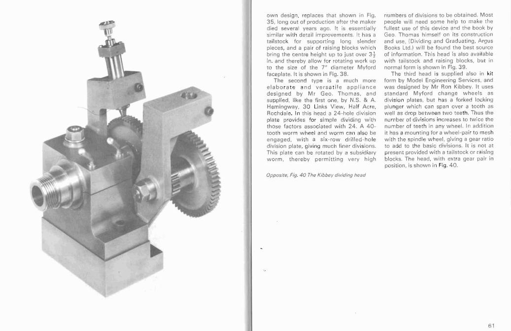
Opposite, Fig. 40 The Kibbey dividing head
numbers of divisions to be obtained. Most peop le will need some help to make the fullest use of this device and the book by Geo . Thomas himse lf on its construct ion and use, (Dividing and Graduat ing , Argus Books Ltd.) will be fou nd the best source of information. Th is head is also ava ilabl e with tai lstock and raising blocks, but in normal for m is shown in Fig. 39 .
The third head is supplied also in kit form by Model Enginee ring Serv ices. and was designed by Mr Ron Kibbey. It uses sta ndard Myford cha ng e whee ls as division plates, but has a fork ed lock ing plu nger which can span over a tooth as we ll as drop be tween tw o teeth. Thus the num ber of divi sions increases to tw ice the number of teeth in any w heel. In addition it has a mount ing for a w hee l-pa ir to mesh w ith the spindle w heel. giving a gear ratio to add to the basic divisions. It is not at present prov ided with a tailstock or raising blocks. The head, w ith ext ra gea r pair in pos itio n, is show n in Fig. 40 .
6 1

CHAPTER 11
Dividing Heads and, Gearcutting The availabi lity of a divid ing h ea~ is again essentia l for doing gearcutti ng on the mill ing mach ine. Of cou rse the re are types of gears one just cannot do, bu t ordinary spur gears can be done perfectly wel l for mod el engineering purposes. wh ere nei the r high speeds. extre me silence, nor high rates of pow er tr ansm ission are demanded. The design of gear s is a subject outside the scope of this book, which is intended to deal with workshop ope rat ions. but there are plenty of sources of informa t ion on gear design . The simp le type of div iding head already illu strated w ill serve very w ell if the gears to be cut have such a num ber of teeth as the indexing cha nge w heels can deal wi th. Bu t if the number requ ired cannot be got from exist ing wh eels, then a more complex head such as the Myfo rd. w ill be needed. Fig. 37 shows th is in use cutting the teeth of a pin ion w hich are integral with the shaft. The blank was turne d to t in. dia meter on the part to be held and this was gripped in the sta nda rd Myford t in. coll et. w hi le the other end of th e com po nent being centred wa s supported by a 60 degree centre in the ove rarm f itt ing. This picture show s the steady bracket descr ibed in the last chapter in use. The cutter is a simple flycutt er in a boring bar
held for conven ience in a boring head. It is shown in close-up in Fig. 41 . The prof ile w as established by grinding to suit a whee l of the sam e pitch w ith slight ly mo re teeth. The variat ion is so small as to be of no importance. especial ly as the pinion rotates at only a low speed.
But if several gears are to be made. and especia lly if duplicates may be w anted lat er, it can be w orth while to invest in one or more prope r disc type gear cutt ers of wha t is now universally known as the 'Brow n & Sharpe' type, because they we re deve lop ed by the famous fir m of Brown & Sharpe in U.S.A. many years ago. They are of course now made by Britis h firm s as w ell. and by others all ove r the w orld . to an accu racy of in ternational stand ards. far be tter than anything that is needed fo r model engineering, and are prope rly back ed off as w ell as being made f rom high speed ste el. No single cutt er will properly deal with all number of tee th, so they are made in sets. ea c~ cutter dea ling wi th a limited range . and each bea rs an ident ify ing number. The range runs as fo llows: No.1 135 to a rack No.5 21 to 25 No. 2 5 5 to 134 No. 6 17 to 20 No.335 t05 No.7 14 to 16 No. 4 26 to 34 No.8 12 and 13
I III
Fig. 4 1 Close-up of fl ycu t ter and pin ion
Fig. 42 Gearcutting with Brown & Sharpe cutter
63 62
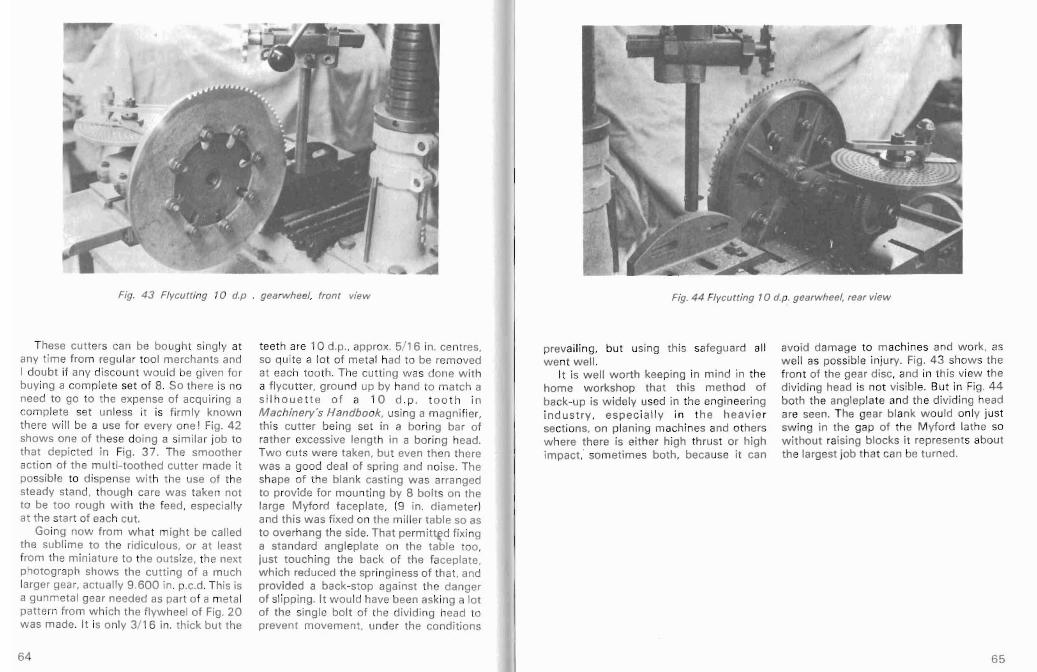
Fig. 43 Flyc utting 10 d.p
These cutters can be bought singly at any tim e from regular tool merchants and I doubt if any discount w ould be giv en for buying a complete set of 8. So there is no need to go to the expense of acquiring a complete set unless it is fir mly kno w n there w il l be a use for every one ! Fig. 4 2 shows one of these doing a similar job to that depicted in Fig. 37 . The smoother action of the mul t i-tooth ed cu tter made it possib le to dispense with the use of the steady stand. though care was taken not to be too rough wi th the feed. espe cially at th e start of each cut.
Going now from w hat might be called the sublime to the ridiculous. or at least from th e miniature to the outsize . the next photograph shows the cutting of a much larger gear. act ually 9 .600 in. p.c.d. This is a gu nmetal gear needed as par t of a metal pattern from w hic h the flyw heel of Fig. 20 was made. It is only 3/1 6 in. thick but the
. gearwheel, fron t view
teet h are 10 d.p.. approx. 5/ 16 in. cent res. so qu ite a lot of metal had to be removed at each too th. The cutting w as do ne wi th a flvcut ter. ground up by hand to match a s i l ho u e tte of a 10 d .p . t o o t h i n M achinery's Handbook. using a m agnifier, this cutter bein g set in a boring bar of rather excessive length in a bo ring head. Two cuts w ere taken, bu t even then there w as a good deal of spring and noise. The shape of the bla nk casting wa s arranged to provide for mo untin g by 8 bo lt s on the large Myford faceplate. (9 in. diamete r! and th is wa s fi xed on the miller table so as to overhang the side. Tha t permittgd fixing a standard ang leplate on the table too. just to uchi ng the back of the faceplate, which reduced the springiness of that. and provided a back -s top against the danger of slipping. It w ould have been asking a lot of the single bolt of the dividing head to prevent movem ent, und er the co ndit ions
Fig. 44 Flycutt ing 10 d.p . gearwheel, rear view
prevailing. but using this safeguard all w ent w ell.
It is well worth keepi ng in mind in th e home w orkshop th at th is method of back-up is wi dely used in the engineeri ng in d ustry . espe c ial ly i n t he heav ie r sect ions, on planing machines and others w here there is either high thrust or high im pact,' sometimes both, because it can
avo id damage to machines and work. as w ell as possible injury. Fig. 43 show s the front of the gear disc. and in this view the divid ing head is not visibl e. But in Fig. 44 bo th th e angleplate and the dividing head are seen. The gear blank w ould only just swing in the gap of the M yford lath e so w ithout raising block s it repres ents about the largest job that can be turned .
65 64

CHAPTER 12
Dividing Heads and Tool Making There are many occasions in tool making rough and ready methods just w ill not do. w hen dividi ng is nec essary. Multiple and as in the next example the physical edged cutt ing too ls like taps. reamers, di fficulty of getting at the metal that has milli ng cutters, cou nte rsinks. etc. all really to be taken aw ay mo re or less sett les that need dividing devices to produce the best mechan ica l divi ding must be employed . results, even though some of the simple Fig. 4 5 show s the fl uti ng of a long-thread cutters can we ll be made by f iling or Acme tap which is held in a collet in the free hand gr inding. However, the form of spindle of a simple dividing head, using the teeth or flutes sometimes sett les that change w heels for the divid ing. In order to
Fig. 45 Flu ting Acm e thread tap
obtain the maximum swa rf clea rance this Another example of the use of the tap has five flutes. The head has no dividing head, th is t im e cou pled w ith the tailstock so the outboard end of the tap is use of a small rotary tab le, is shown in rested on a pair of Picador bloc ks and the Figs. 46 and 47 . The wo rkpiece to be
clamp rests on anoth er pai r. These are produced was a fine tooth mill ing cutter very usefu l acce ssories for mi lli ng opera with a roun d end for routing or hand
tions. Of course each tim e that a flute is m illing on the light alloy cy linder head of a completed the clam p has to be released car eng ine. The commercial ly avai lab le
before the work can be rotated to the cutters for use in elect ric drills had such position for the next flute. A suitable coarse teeth that once they touched the tailstcck. w ere it available, would obv iate surface of the alloy they we re uncontrollthe need for th is. The 5 flu tes are obtained able and pulled sideways so vio lent ly that
by mo ving 12 teeth at a ti me on a 60 damage to the cylinder head was almost a tooth wh eel. The cutte r being used is a ce rt ain ty. So as fine pitch cut ters
com mercial tap-f lut ing cutte r picked up appea red to be not purchasable it was
cheaply at a sale. These cutters are made decided to make one. The bla nk, of a
w it h a som ewhat lo p- sided roun ded carbon steel similar to silver steel but
prof ile speci ficall y for this duty, but if it somew hat low er in carbon, wa s made to
had not been available, a flycutt er w oul d hold in a collet and w as give n a small
have been gro und up to the profile of a recess in the end for the flut ing cu tte r to simil ar tap. The prof ile is not desperately run into. The div idi ng head , with a 50 im por tant and a small error wou ld not to oth change w heel an its spindle . was
mounted on a stee l plate so that the end matt er.
Fig. 4 6 Cut ting teeth of ball -end cu tter
66 67

Fig. 4 7 Close-up of ball-end cutter
of the wo rk-piece w as beyond the centre table traversed along br inging the cutte r of the rotary table by half its diameter. In int o operation cutting along th e cy lindrica l other w ords , the centre of the ball end port ion. When the table was arrested by was over the centre of the rotary tab le. the te mporary stop block, the rotary table The axis of the work w as on the rot atio n wa s turned by means of it s w orm, so the cent re. This is not app arent fro m th e dovetail cutt er continued cutting round pho tog raph, but w as an essent ial feature the ball end of the work. W hen the culler of the set-up. A stop block wa s clamped ran into the recess, the feed w as reversed to the underside of the milling mach ine fi rst wi th the rotary table, then wit h the table with a toolmaker 's clamp, visi ble in main table, back to the start ing point , t he pho to g raph , to l im i t the ta bl e w here the cu tt er w as clear of the w ork movement positive ly to this posit ion. In sha nk , The d ivid ing head was then the other direct ion the movement of the indexed one tooth on the w heel. and atable brough t the cutt er to a part of the new cut st arte d, Eventua lly all 50 cutstoo l shank sm alle r than the diameter at we re comp leted as shown in Fig. 4 7. the bottom of the flu tes so that indexing The working ' diameter of this tool is fcould be done w ith th e cutte r in the clear. in. and tlgere are 50 perfect teeth. The too l The cutter used w as a carbon steel one w as hardened and tem pered, and w hen made originally for producing locom ot ive put to use in an electric dri ll was found to lubricator ratchet whee ls, w it h a 60 be ent ire ly sat isfac tory, It worked com degree single angle. W ith the axis of the pletel y chatt er-free, wi th no ten dency towork parallel to the table a cut was run away, and in spite of its fine and started at the requ ired full depth, and the shallo w teeth , removed metal at a very
Fig. 48 Gashing fl ut es in large countersinking tool
grati fyin g rate. The w ork on the ports in this w as to use a vertical slide. There was the alloy head wa s comp leted to the great qu ite a lot of me ta l to be taken out of the satisfaction of the user, leaving a beautiful 25 flutes in this decided ly tough steel , and smooth surfa ce for the gas flo w . as usua l the cutt ing wa s a long wa y from
An other example of cutting tool making the anchorage point, so the steady stand is show n in Figs. 48 and 4 9. A large 60 was brought into use at the back of the degree countersink w as need ed for a head, as it proved too diff icul t to set it at com mercial operation on steel tubes, the the same side as the cutter. Howe ver, it tool being about 2 -!- in. diamete r. It wa s served quite w ell in that posit ion and made with an interna l fo rm ident ical w it h t here w as never any suggest ion of the Myford lathe spindles from a carb on insecurity. ma nga nese ch rom e all oy of known The main gashes fo r the flutes w ere identity, so that subs equent hardening taken out first, w ith two cuts dow n each coul d be done w ithout risk of failure in a flu te. Then the head wa s t il ted to a new co mmerc ia l es t ab li shm en t wit h angl e and another series of cuts take n to knowledge of th is steel. In the pictu re it is accomplish the rel ief. Because of the show n moun ted on the Myford divid ing coni cal shap e of the work the vert ical slid e head hav ing th e f lut es cut wi th a specia l had to have it s base set at an angle to the angle fo rm disc type cutt er. Beca use of miller table. A ll these appa rently comth e peculiar angl es w hich are involved it plicated settings had to be established was necessary to be able to set the head experi mentally (though possib ly w ith a lot with it s axis at an inclinat ion to the table, of effort they mig ht have been calculated) and it proved that the simp lest way to do to give the desired for m of the cutt ing
69 68
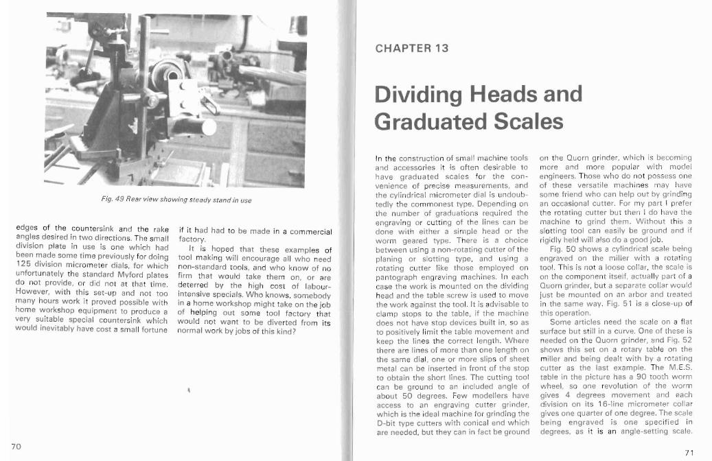
Fig. 49 Rear view showing s teady stand in use
edges of the countersink and the rake angles desired in two direct ions. The small division plate in use is one wh ich had been made some time previously for doing 12 5 div isio n m icrometer dial s. for w hich unfo rtunatel y the standard Myford plates do not provide , or did not at that t ime. How ever, w ith th is set -up and not too many hours w ork it proved possible with home workshop equipment to produce a very suitable specia l countersink w hich would inev itably have cost a small fortune
if it had had to be made in a com mercial factory.
It is hoped that these exampl es of too l making wi ll encourage al l who need non-standard too ls, and wh o know of no firm th at w ould take them on, or are deterred by the high cost of labou rintensive specials. Who kn ows, somebody in a home workshop might take on the job of hel ping out some tool fact ory that w ould not wa nt to be diverted from its normal w ork by job s of this kind?
CHAPTER 13
Dividing Heads and Graduated Scales In the construction of sma ll machine tools and access ories it is ofte n desirable to have gradua ted sca les for the co nvenience of precise measurements, and the cy lindr ical micrometer dia l is undoubtedly the com mo nest type . Dependi ng on the number of graduations required the eng rav ing or cutt ing of the lines can be done w ith eit her a simp le head or the worm geared type. There is a choice between usin g a non-rotati ng cutte r of the pla ning or slott ing type, and using a rotat ing cutt er like those employed on pantograph engraving machines. In each case the work is mounted on the d ividing head and the table screw is used to move the work against the too l. It is advisable to clamp stops to the table . if the mac hine does not have stop devices built in . so as to positively limit the table movement an keep the lines the correct length. W here there are lines of more than one length on the same di al, one or more slip s of sheet metal can be inserted in front of the stop to obtain the short lines . The cu tting tool can be gro und to an included angle of about 50 degrees, Few modelle rs have access to an engraving cutter gr inder. which is the ideal machine for grinding the D-bit type cutters with conica l end w hich are neede d. but they can in fact be ground
on the Quorn grinder. w hic h is becom ing more and more popular wi th model engi neers. Those w ho do not possess one of these versatile mac hines may have some friend w ho can help ou t by grinding an occasiona l cutter. For my par t I prefer the rotating cutter bu t then I do have the machine to grind them. W ithout this a slotting tool can easily be ground and if rigid ly held w ill also do a good job,
Fig. 50 shows a cy lindrica l scale being eng raved on the mill er w ith a rot at ing too l. This is not a loose co llar, the scale is on the co mponent itself. act ually par t of a Quo rn grinde r, but a separate co llar wou ld just be mount ed on an arbor and treated in the same way. Fig. 51 is a close-up of th is operation,
Some art icles need the sca le on a flat surface but sti ll in a curve, One of these is needed on the Ouorn gri nder, and Fig, 52 shows this set on a rotary tab le on the miller and being dealt with by a rot at ing cutte r as the last example. The M. E.S. table in the pict ure has a 90 tooth worm w heel. so one revolut ion of the worm gives 4 degrees movement and each division on its 16- line micrometer collar gives one quarter of one degree, The scale being eng raved is one sp ec ified in degrees, as it is an angle-setting scale.
71 70
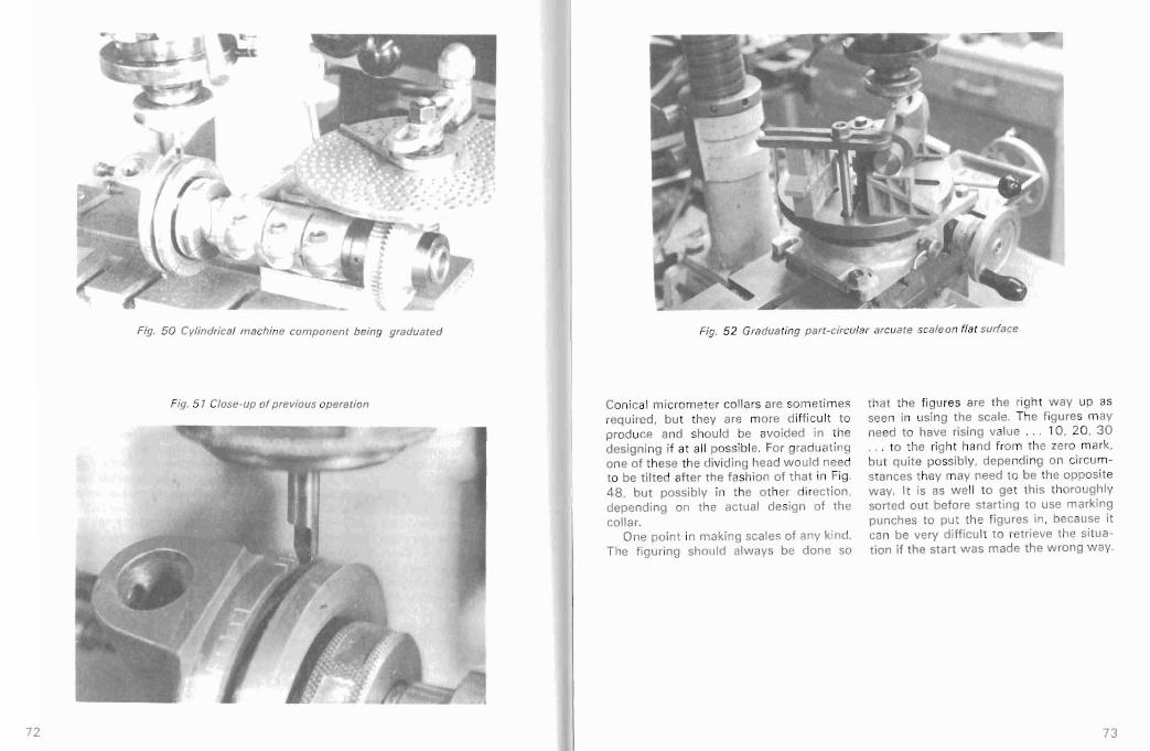
Fig. 50 Cylindrical machine com ponent being graduate d
Fig. 5 T Close-up of previous operation
Fig. 52 Graduating part- circular arcuat e scale on fla t surface
Conical mi crome ter collars are sometimes requ ired , but they are more diff icult to prod uce and should be avoided in the designing if at all possible. For graduat ing one of these the dividing head would need to be t ilted after the fashion of th at in Fig , 48. but poss ib ly in the other direction. depending on the actua l design of the co llar.
One po int in ma king scales of any kind. The fig uring should always be done so
that the figures are the right w ay up as seen in using the scale . The f igures may need to have rising value . . . 10 , 20 , 30 . . . to the right hand from the zero mark, but quite possib ly, depe nd ing on circumstances they may need to be the opposite way. It is as w ell to get this thoroughly sorted out before starting to use ma rking punches to put the figures in. because it can be very di fficu lt to retrieve the situation if the start was made the wrong wa y.
73 72

CHAPTER 14
Cutter Speeds for Vertical Milling In gene ral I a~ afraid model engineers do not have very clear ideas about how fast they should run their lath es, dri l ls or mi lling machines. To run too slowly extends the w orking time unnecessarily, but to run too fast will soo n blunt a cutter and may also cause poor w ork finish through cha tter. The wear on mil ling cutters (apart from flyc uttersl is quite importa nt because of the trouble of sharpening t hem , and broken cut ters can be qu ite an expe nse. The pri nciples w hich govern the speeds of cutting metal in othe r mac hines such as the lathe and dri ll can be taken as a useful guide, in the sense that any speed which an a part icular materia l w ill blunt a lathe tool or drill wil l likewise blunt a mill ing cutter. But on the vertical miller there are other problems too. Generally t he point of cutting is much furth er from the supp ort than that of the lathe tool. It wi ll also be a long wa y co mparatively from the spind le bearings. The work may be much further from the slideways than it wou ld be from the bed of the lathe. The cutt ing tool is normally unsupport ed at it s cutting end, and it s own elasticity is added to that of the chuck, spindle , work, etc . So speeds which might be feasible on the lathe may well be fou nd much too hig h on the mi ller.
As an example, turni ng back to Fig. 20 wi ll show how eleva ted the surfac e of the w ork is f rom the table slides, and in th is exam ple low speed s were essential to obtain a reasonably goo d finis h.
The rates of feed and dept h of cut w hich are commonp lace on industrial machines are quite out of order in the home workshop. Not only are industria l machines heavy and rigid, so are the wo rk holding dev ices, and the work it self is much more robust and rigid. Also, and th is app lies particu larly when cu tting stee l, these machines can usually flood the cutter with coolant , taking away the heat generated in the cutt ing ope ration, and that is no t norm ally possible on machines in the home wo rkshop. So Table III has been compiled to give som e gu idance in the kind of opera t ions which have been described in the boo k. It is based on using speeds w hich wi ll conserve the sharpness of the cutters like ly to be used. For f lycu tters, commercially made endrni lls . and Brown and Sharpe gear cutters, the tools themselves wil l be properly hardened high speed stee l. For the Woodruff cutters it is based on these being home made cutters produced from carbon stee l or 'silver' st eel (w hich is a carbon stee l with about 1.2% carbon and no alloy) . More than one
article in Model Engineer in years past has described methods for maki ng gea r cutters of the Brow n and Sharpe type. and I hav e some of these myself, made from plain carbon steel of abo ut 1% carbon . Such cutters must be run mo re slow ly than the high speed steel cutters of com mercial make, but it is possi ble that a w ide r var iety of tools w il l in fut ure be made in the home w orkshops, as a bett er understa nding of too l making and th e con t ribution w hich the vert ical miller can pro vid e com es to be recogn ised . The cutting speeds to be used with such tools w ill need to be arranged to sui t the tool materi als and the w ork they are doing.
The proper mou nt ing of tools in the
miller is a matter of grea t importance. Reference has already been made to too ls which screw di rect ly on the spind le nose , and anothe r chapter in this boo k w ill give descriptions of the milling chucks w hic h are currently availab le.
It will be foun d that some of the millers at present on offer have spee d ranges wh ich do not go low enough to match the bottom end of the recommended speeds on Table II I. This is un fort unate, bu t it is a fact of life, and one mu st do the best one can w it h it, even it it means occasional ly borrow ing the use of a friend 's machine. Naturally it w ill t end to in flu ence the decision w hen thinking of pu rchasing a machine.
74 75
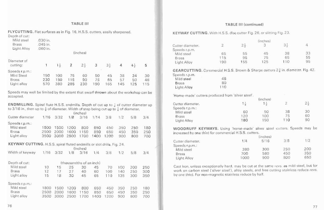
TABLE III
FLYCUTIING . Flat surfa ces as in Fig. 16, H.S.S. cutters, easily sharpened. Dep th of cut :
Mild steel .0 30 in. Brass .0 4 5 in. Light A lloy .0 60 in.
(inches)
Diameter of cu tt ing : 1 I t 2 2 l 2 3 31 4 4 t 5
Speeds r.p.rn.: Mi ld Stee l 150 100 75 60 50 45 38 34 30 Brass 2 30 150 115 90 75 6 5 57 50 46 Light alloy 57 0 3 80 28 5 230 190 165 14 5 125 115
Speeds may well be limited by the extent that sw arf thrown about the workshop can be accepted.
ENDMILLING . Sp iral flute H.S.S. endmill s. Dept h of cut up to ~ of cutter d iame ter up to 3/16 in., then up to -i- o f diame ter. Wid th of step being cut up to } o f d iameter.
(inches) Cutt er diameter 1/1 6 3/32 1/8 3/16 1/ 14 3/8 1/2 5/8 3/4
Speeds r.p.m .: M ild steel 18 00 15 00 1200 800 65 0 450 3 50 2 50 180 Brass 2500 2000 1600 11 50 850 650 450 350 250 Light alloy 3500 3000 2 500 1700 140 0 120 0 900 800 70 0
KEYWAY CUTIING . H.S.S. spiral flu ted endmill s or slot dr ills. Fig. 24 . (inches)
W idth of keyway 1/ 16 3/ 32 1/8 3/ 16 1/4 3/8 1/2 5/8 3/4
Depth of cut: (thousandths of an inch) Mi ld steel 10 15 25 30 4 5 70 100 200 2 50 Brass 12 17 27 40 60 10 0 140 250 300 Light alloy 15 18 30 45 65 1 10 13 5 300 3 50
Speeds r.p.rn.: M ild steel 1800 1500 1200 800 65 0 450 350 250 180 Brass 2500 2000 1600 11 50 850 650 450 350 250 Light alloy 3500 3000 2500 17 00 1400 1200 900 800 700
TABLE III (continued)
KEYW AY CUTIING. With H.S.S. disc cutter Fig. 26, or slitt ing Fig. 23 .
(inc hes) Cutter diameter. 2 2t 3 3 '2 4 Speeds r.p.m.
Mild stee l 65 55 45 38 33 Bras s 1 15 9 5 75 65 55 Light Al loy 190 15 5 125 110 95
GEARCUTIING. Commerc ial H.S.S. Brown & Sharpe cutters 2~ in. diameter. Fig. 42 . Speed s r.p.rn.
M ild steel 48 Brass 80 Light A lloy 11 0
'Home-made' cutters prod uced from 'silver steel' , (inches)
Cut ter diameter, 1t 12t 2 2}
Speeds r.p.m.: M ild steel 60 50 38 30 Brass 120 100 75 60 Light A llo y 180 150 110 90
WOODRUFF KEYWAYS. Using 'home-made' silver steel cu tters, Speeds may be increased by one third for co mmerc ial H,S.S. cu tters.
(inc hes) Cutter diameter. 1/4 5/ 16 3/8 1/2 Speeds r.p.rn.:
M ild steel 380 300 250 200 Brass 70 0 580 450 3 50 Light All oy 1000 900 800 650
Cast iron, un less excep tiona lly hard, may be cu t at the same revs . as mi ld stee l, but for work on carb on stee l ('silver steel'). alloy steels, and free CU ll ing sta in less reduce revs. by one third. For non -magnetic stain less reduce by half.
77 76

CHAPTER 15
Work-holding with Difficult Shapes Problems do arise from time to time regarding the meth ods of holding work in the m illing machine. In fu ll sca le engi neer ing th ese problem s are not nearly so acute as compon ents are more solid and clam ps can be app lied w ith out crus hing the pieces. Often wi th model parts it is di ff icu lt to ge t a hold sufficien t ly fi rm ly withou t more or less mutilat ing the piece. One method I often use bo th for cast ings and bar materia l is to arrange fo r an accurate chuc king piece to be left on the co mpone nt unti l a ll operati ons are co m plete and th en to remove th is. Generally this p iece is made to suit one of ' the M yford collets, from t in. diam eter dow nw ards, since the co lle ts do hold the part w it h great accuracy, and after turn ing operations it can be tra nsferred to the miller w ith the coll et placed in a di viding head; even if no indexing has to be done , the head acts as a very effec tive vice.
Some times thin components prese nt prob le ms in ho ld ing on the m ill ing mach ine. If one side is already fl at one can use do ub le-side d sticky tape, available from drawing off ice supply shops and some stat ioners. If tw o or three strips can be used , an astonishing ly firm grip can be obtained, w hich w ill stand up to shea r forces induced by m illing. I have also in an
industrial p lant stu ck down metal which had to be tooled all th e w ay across th e piece, on a fal se base w ith woodw ork er's glue and a sheet of new spaper. Afte r the operation s are completed a f ine chisel is knocked in between the parts and the paper tears w ithin its thick ness, so th e pieces come apa rt with some paper st icking to each . This can th en be washed off w it h hot w ater. There is not hing very orig inal abo ut this, of course, it is an ageold pat ter nrnakers' meth od of produc ing a patt ern wh ich has eve ntua lly to be in halves , but it is a sound me thod not nea rly so well known as it sho uld be. Fig. 53 shows a light alloy cast ing being faced rig ht across w ith a flycutter, th e cas ting being stuck to the table wi th sticky tape and no th ing else.
How ever, the var io us examples give n throughout th e book shou ld serve to show how to undert ake a really wide range of jobs . A t the risk of seemi ng repe ti tive I would agai n st ress th at it is often worth w hile to make a ji g fo r holding or locat ing th e work , just to make sure i t can be held fi rmly enough without damage in the rig ht attitude. The kind of jigs and f ixt ures needed in modelling seldo m involve mo r than a few mi nutes or perhaps an hour to make, and if this safegua rds the compo-
Fig. 53 Tape-held w orkpiece being fly cut
Fig. 54 Three-face ang leplate used to align vee-blocks
79 78

Fig. 55 Three-face anglepla tes used as main packing
nent , as w ell as the tool s and machin e. it an g l e p l a t es , wh i c h ar e sent out is time we ll spent. If a duplicate compo unmachined in lig ht alloy, are in three nent is ever needed that w i ll be produce d sizes very convenient for use in home expedit iously w ithout risk too. workshops and can easily be faced up on
the M yford lathe bo ring table or faceplate. A ngleplates Fig. 54 show s one of them set across a A new type of anglepl ate has been mil ler tabl e to locate the tw o vee-block s in int roduced by Hemingw ay. This has three w hich th e w ork is rest ing. Fig. 55 show s faces machined at 90 degrees to one another pai r used as main packing s w ith ano the r. I have found over many years Picado r stepped blocks on top to give the that cast- in slot s in ang lep lates never last bi t of heigh t adjustment for the clam p seem to be in the righ t place for any job, plates. So many sizes are ava ilab le by and it seems bet ter to just drill a hole selecting di ffer ent atti tudes of the se blocks wh ere i t happens to be needed. These tha t they are very useful indeed.
CHAPTER 16
Milling Chucks for Safe Cutter Holding
The newcomer to vert ical milli ng m ay wo nde r w hy there should be any need for special chucks for milling cutters, and especially w hen he sees that these are fair ly expensive accessories. may be tem pted to make do w ithout one. But first of all it is nece ssary to realise th at the forces acti ng upon mil ling cutters in use are generally quite diff erent from those act ing on dr il ls in a dri ll ing mach ine or lathe. The drill is usually subjected, except at the mo ment of complet e penet ration , to axial fo rces on ly, whi ch press it mo re and more firmly in to the Morse taper hole in the spindle. Even if it is held in a drill chuck and has a para llel shank, t he same thing applies.
But th e milling cutt er is subjected to
transverse for ces, across th e axis, and unless it is screw ed on the spindle, these forces have a co mponen t wh ich is pressing against the inside of the Morse tap er hole, and thereby try ing to cause the cutter to slide out of the spindle . Each ti me the spindle rota te s the pres sure is transferred to the opposite side of the hol e. and this waggles the tool out of the spind le. So fi rst of all , any tool mounted by a taper shank, whether it is a chuck or a solid endm ill w ith taper shank, MUST be
provided w ith a drawbar through the spindle to stop th is ten dency to w ork out.
For cutt ing tools w hich in operat ion produce no end forces that precaution is suff icient. But all the spiral fl uted endmills and slot dr ills do generate end forc es, tending to screw them out of the holding device. (Strict ly speaking this app lies to cutt ers w ith righ t hand rotat ion, like a drill, and right hand f luting , also like a drill. But as it w ould be remarkable for any others, tho ugh manufactured, to be fou nd in a home wo rkshop , the others can we ll be disregar ded.) So spiral fluted cutters w ill t ry to work ou t of a chuck, if parallel shanked, and must be fo rcibly prevented. It is not good enough to ho ld th em in a thre e-jaw lathe chuck, especially since most of th ese exert mo re pressure at the in ner end than th e out er, through wear exist ing in the jaw slides, in eff ect givi ng them a slight tape r.
This is w here the specially des igned mill ing chuck com es into its ow n. There are tw o basic types, but each is arranged to grip the cutter firmly on its paral lel shank by a split coll et clo sed by a screw thread forcin g the collet into a conica l part of the chuck. In addition one typ e uses cutt ers formed with a specia l shaped end ,
81 80

Fig. 5 6 Clare milling chuck
and the ot her type uses cu tt ers w it h a collet is no t only retained in the chuck sho rt screw th read at the end of the body by all internal ly screw ed cap w hich shank. The first of these, the Clare, has a fits on the body , but is also closed on the rect angular end fo r the cu tt er, and this shank by it. The co llet screw s into another end is undercut by m illing. After passing it th read in the cap, which ensures that it through a rectangular slot in the co llet, the loosens when requi red, a small spanner cutter is turned through a smail angle, so being prov ided by the makers for this the part not und ercut overhangs the end purpose. This type of chu ck w ill in fact of the collet, and cannot slide out. The hold cu tters w hich do not have the 'tee'
Fig. 5 7 Clarkson milling chuck Fig. 58 Osborn mill ing chuck
end, and have jus t a plai n rou nd shank, hand w ithout th e use of a spanner. There though of cou rse the security feature is is provision w ith each of these for using then non-existent . But for small cutt ers 't hrow -aw ay' cutters, w hich are made and light duty it w ill serve very we ll. cheaply in sizes up to :l- in. These have a
The other type of chuck, made both by plain shank. unsc rewed, of t in . diameter Clarkson and Osborn , uses only a screwed w hate ver the size of th e cutt ing portion. shan k typ e of cutt er and cannot be used w hich has a sma ll f lat in one place . They excep t w ith this. Th e screw th read on th e are set in an adaptor w ith a small screw at shan k, w hen subjected to the torque the side, w hic h bears on the flat , and this necessary to dr ive th e cu tte r, prov ides the is suffic ient to prevent their working out of force to clos e the collet and th ereby gr ip the chuck. The idea of th ese cutt ers is tha t the tool shank. A cent re device inside the they are made so cheaply that in a combody engag es w ith the cen tre dimple in mercial eng ineering shop it wi ll co st more the end of the cutter to reduce fr ic tion to re-sharpen one th an to replace it by a forces that w ou ld hamper rotat ion of the new one . Whe ther or not that is really true
cutte r. The Cla rkson chuck needs a will depend on the par t icular establish
spanner, provided w it h th e to ol. to release ment in w hich they are being used, bu t in the co llet for chang ing cutters. T he the home worksho p, if the re is a Quam Osborn e uses a finer thread on the grinder. it will be feasible t o re-sharpen secur ing sleeve . toget her wi th some lost them at a worthwhile cost in time and motion provisions. and can be released by t rouble, for a w hile , until a certain amount
82 83
of shortening has taken place . All the cutte rs with screwed ends to
suit the Clarkson and Osborn chucks have Whitworth form threads 20 per inch irrespective of diameter. On t in . shanks this conforms to B.S.W. and on t in . shanks to B.S.F. fo r both of which dies can be readil y obtained . But fo r other diameters, if one needs to make a special cutter in the home workshop. screwing a shank 20 threads per inc h is not a difficult task. Making the specia l ends for the Clare cutlers is not quite so easy in my view. but the Clare chuck has the advantages of a sho rt overhang and a sm aller diameter of body, This is part icularly useful when holding wo rk in a 3 or 4- jaw chuck on a dividing head, when some times i t is difficult to clear the chuck jaws. But all
these chucks can be fu lly recommended as being good precision tools which provide complete security against cutte rs working out in use. If an accident of tha t kind happens due to not having a security chuck. a spoiled component is certa in, a broken Culler is possible. and I have seen this happen on a numbe r of occasions, So do be w arned , and don' t think the cost of a proper chuck is too high to face.
Pho tographs of the three chucks mentioned are shown in Figs. 56 , 57 and 58. The Clarkson Autolock chuck shown here, as we ll as in pictures in the tex t, is f itt ed w ith a damping ring . After the chuck is f ixed in the Morse taper, this ring can be screwed up to cont act the end of the mach ine spindle, giv ing extra support aga inst vibration.
84
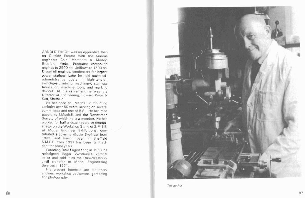
ARNO LD THROP wa s an apprentice the n an Outside Erector w ith the famous engineers Cole. Marchent & Morley. Brad ford. Yorks. Produc ts: compound engines to 2 50 0 hp , Uniflows to 1500 hp. Diesel oi l engines, condensers for largest pow er stations. Later he held technica ladm inist rat ive po sts in high- tensio n swi tchqear. mi ning machin ery . stainless fabricat ion. mac hine tools, and marking devices. A t his ret ireme nt he was th e Dir ector of Engineering, Edw ard Pryor & Son. Sheffield.
He has been an I.Me ch .E. in mo unting seniori ty over 50 years, serv ing on several committ ees and one of B.S.1. He has read papers to I.Mech.E. and the Newcomen Socie ty of w hich he is a mem ber. He has worked for half a dozen years as demonstrator on the W orkshop Stand of S.M. E.E. at M od el Engineer Exhibit io ns, contributed art icles to Model Engineer from 1932, and having been in Sheff ield S.M .E.E. from 193 7 has been its President fo r. some year s.
Founding Dore Engineering in 19 63 . he redesigned Edgar Westbury 's vertic al mille r and sold i t as the Dore-Westbury unti l tra nsfe r to Model Engin eering Services in 19 7 1.
His present interests are sta tionary eng ines. wo rkshop equ ipment , gardening and phot ography.
The author
86 87

Index
Abwood milling attachment 12 Amo lco m i ll i n g atta c h m en t a nd
machine 21 A ngleplates 80 Angleplate used as backstop 27 , 29 Arbors for sli tt ing saw s and disc cutters 3 5 As tra milling machin e 22
Boring operations 45 Bori ng heads 30
Chuc ks, Clare, Clarkson, Osborn 82Clutch teeth 55 Connecting rods 43 Crosshead slides , engine bedp late 30
Divid ing heads . de scr iption an d principle 54
Plain typ e. change wheel indexing 55
Myford w orm-geared type 57 Use of div ision plat es 57 Use of locating blades 57 Packing block for centre height 57 Steady stand for extra rigidity 56
Dividing head s and gear-cutting 62 Plain type 62 Pin ion cutt ing 62 Large gear cutting 64
Dividing heads and graduated scale s 71 Planing/slott ing and rotating too ls 71 Table stop s and line length co ntrol 7 1 Cutting/engraving cy lindrical scale 72 Cutt ing/engraving flat arcuate scale 73 Con ical micrometer dials 73 Markin g fig ures of scales right way 73
Divid ing heads and tool-m aking 66 Fluting screwing tap 66 Cutt ing f ine tooth mil ling cutter 6 7 Cutting large counter sink 69 Specia l division pla te. 2 5 hole 70
D-b it fo r hol e cen tri ng to start dri lls 47 Dor e-W estbury mill ing machin e 14
End-roundi ng : Fil ing coll ars and rollers 52 Using rotary tab le 52 Fittings for rot ary table 52 Rounding engine cranks 52 Direc tion of table rotation 52 Lock ing pre cauti on s fo r ex te rna l
work 53 Engine bedpl ate bearing jaw s 33 Engine cyli nder solepla te 30 Evolut ion of ver t ical mi ller 12
Flut ing operat ion s. locom ot ive rods, cor rec t f lut e form 4 4
Rods for Briti sh engines 43 Rods for Canadian and Am erican
engines 43
89 88

Flywheel (in halves) joint face 3 1
Gear cutt ing 62 Grinder for engraving cutlers and o
bits 7 1
Identi fication of cutte rs etc . by mark ing when made 42
J ig-boring : Meas uring by table screws 46 Wri tten record of measurem ent s 47 Example of beam for model eng ine 47 Trip gear lever of model eng ine Boiler tube pla tes Avoidance of back-l ash erro rs
J igs for milli ng opera t ions
Keyways for pla in sunk keys: Endmilling feather keyways on
shahs Keyways on taper shafts wi th
angleplate Disc cutter milling of keyways
Locti t ing for permanent assembly Long com ponents, holding problems
Machine specifica tions. tab le of M axim at milling attachment
48 48 46 78
plain 37
t ilti ng 38 41
27 38 . 49
24 22
Me ntor mi lli ng ma chine 22 Mill ing cutters. mu lti -tooth:
Early (19 th century ) 'fil e-cut' cutters 12
Facemills 30 Endm ills 38 Slitting saws Disc cutters
3 5 40
Woodruff cutt ers 40 Brown & Sharpe cutters 62 Tap flut ing cutters 67
Ang le cutt ers 69 M illing cutters, single toot h :
Flycutters Connecti ng rod flut ing cutt er
2 7 43
Profi led gear tooth cutters 62 Engraving cutters 71
Milling operations: Flat surfaces parallel
to table 32
Flat surface s square to table 34
Slitt ing and cut ti ng 35 Com ponent f lut ing 43
Tool fluting End rounding Gear- cutti ng
67 52 62
Keywaying 39 W oodruff keys and
keyw ays Bor ing J ig-boring
38 45 46
9 1 90

Profili ng 49 Engraving 71
Myford-Rodn ey milli ng attachment and mach ine 21
Myford collets 62 Myford dividing head 57
Profiling : Circular arcs 49 Locomotive frame s 49 Smokebox and cy linder saddles 49 Pad-bolts 49
Sma l l ar cs d er ived f rom cu rve o f endmills 51
Quo rn grinder for tool sharpe ning 83 Quorn gri nder , parts of 35 ,71
Rotary tab les 52 Rotary tabl e. M.E.S. 52
Senior milling machine 22 Security of mill ing cutters :
Forces act ing upon drills and cutters 8 1 Use of drawbars in machine spindles 81 Positive lock ing of screwed cutters in
chucks 82 Posit ive locking of Tee cutters in
chucks 82 Slitting and cutting operations 35 Speeds of milling cutte rs 74
Tapered sections 29 Throw-away' cutte rs 83 Twin mil ling mach ine 22
Vic es. use of tw o tog ethe r 27
Westbury, Edgar T. 14 Westbury mill ing machine 14 Woodruff keys and keyw ays 38 Work holding fo r difficu lt shapes:
Use of chucking pieces later discarded 78
Sticky tape for thin art icles 78 Glue and paper for thin articles 78 Specia lly made jigs for di ff icult
shapes 78
92 93

",on't let
e" the pressure's on 4" MODEL
ENGINEER
24 issues U.K. £36.00 24 issues Europe £4lI.90 24 issues Sterling Overseas £53.30
Airmail rates given lin request.
If you would like to subscribe to MODEL ENGINEER your remittance and delivery details should be sent to:
ASP Q UCCIi S IW/ I' Hou se
RcdJ;;1I Surrey
RHIIQS
I II I ~ II II ' I I ~ 11 ~ 11 1 111 1 1 1 1 1 1 1 1 1 , 1 ~ 11 1 ~ 1 WilliWOR HO PRACTICESERIES 3 9525 00 117696 6
1. Hardening. Tempering and 8. heet Meta! Work 15. Workholding in the i.athe Heat Treatment R.E. Wakeford Tubal Cain Tubal din
2. vertical Milling in the Homo 9. Soldering and Brazing
Tubal Cain 16 . Electric Motor"
V.1. Cox Workshop Arnold Throp
J . Screwcutting in the Lathe Milflin Cleeve
4. Foundrywork tor the Amateur B.T. Aspin
5. Milling Operations in the Lathe Tubal Cain
6. Measu ring and Ma rking Meta/~
10. Saws ami SawlI1g Ian Bradley
1 I . Electroplating I. Poyner
12. onn« is» ,md Dies Tubdl Cain
I J . Workshop Drawing Tubal Cain
17. Gears and Gear Cutting I. Law
18. B""ic Benchwork Les Oldridge
19. Spring De'ign and 1\t.mutocture Tubal ain
20 . Mt't,l/work and Machining Hint and Tip« Ian Bradley
Ivan LdW 14 . Mak ing mall Workshop 21. Adhes ives and Sea lants 7. The Art of Welding Tools David Lamm as
W.A. Vause S. Bray
2. Vertical Milling in the Hom W orksho The increasing appearance of vertic, I mil lin g machines in model engineers' and other small workshops has brought the versati lit y of thi s type of machine to the notice of a large and growing group of pot ntial users, but until the fi rst edition of the book wa s published in 197 7 there was little easily avai lable guidance for the average amateur or small user. This third, revi sed ed ition incl udes descriptions of many of the very w ide range of operations possible, wi th photograph ed examples, plus informat ion on machines, acce sories, cutters, chucks, r quirements and methods of work-holdi ng.
Arnold Throp enjoyed a long and successful engine ring care r start ing with very larg steam and oil engines and including high tension sw itchgear, mining machinery and machine tool s. He has a hieved over 55 years' membership of the Institute of M echanical Engineers.
ISBN 0-8 5242-843-X
I I IIII II1 I£6.50 net UK 9 78 085 2 428 436