02 ct equipment next
DESCRIPTION
coil tubingTRANSCRIPT
Introduction to Coiled Tubing
Module 02 – Coiled Tubing Equipment
Copyright 2009, NExT, All rights reserved
1

Contents
Types of units
Components of a Coiled Tubing Unit
- Hydraulic Power unit
- Control Cabin / Console
- Tubing Reel
Copyright 2009, NExT, All rights reserved
- Tubing Reel
- Injector Head
- Well Control
- Lifting Equipment
Specialty items
Summary
2

The past – circa 1967
Copyright 2009, NExT, All rights reserved
3

CTU – Paved Road
Copyright 2009, NExT, All rights reserved
4
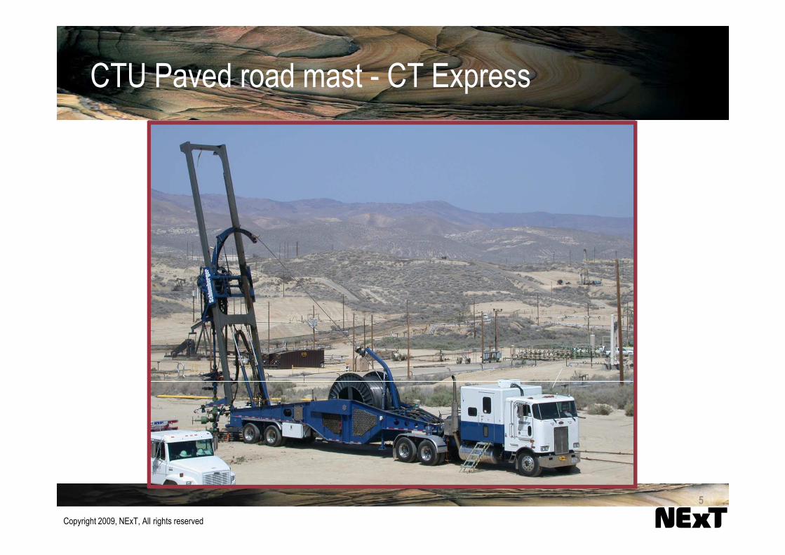
CTU Paved road mast - CT Express
Copyright 2009, NExT, All rights reserved
5

CTU – Single Chassis
Copyright 2009, NExT, All rights reserved
Bob-Tail CTU
6

CTU – Off Road Mobile Mast
Copyright 2009, NExT, All rights reserved
Trailer mounted mast unit for arctic and desert operations 7

CTU – Skid Mounted
Copyright 2009, NExT, All rights reserved
Skid mounted for land or offshore operations
8

CTU – Barge Mounted
Copyright 2009, NExT, All rights reserved
Nigerian barge unitLake Maracaibo
9

CTU – Jacking Barge
Copyright 2009, NExT, All rights reserved
Gulf of Mexico jacking barge
10

Hydraulic Power unitHydraulic Power unit
Control Cabin / ConsoleControl Cabin / Console
Tubing ReelTubing Reel
Injector HeadInjector Head
Pressure controlPressure control
Coiled Tubing Unit Components
Copyright 2009, NExT, All rights reserved
Pressure controlPressure control
Lifting EquipmentLifting Equipment
11

Hydraulic power unit / Power Pack
� Diesel or electric motors
� Drive hydraulic pumps to power
individual systems
� Open/Closed loop systems
Accumulators for the BOPs
Copyright 2009, NExT, All rights reserved
� Accumulators for the BOPs
12

Control Cabins
Primary Control Center for the CT
unit
� CT Controls
� BOP Controls
Monitoring Recording equipment
Copyright 2009, NExT, All rights reserved
� Monitoring Recording equipment
13

Hydraulic unit controls
System gauges Principal gauges
EMERGENCY
STRIPPERBLEED
PRESSURE BLEEDSTRIPPER #2PRESSURE
INSIDE TRACTIONSUPPLY PRESSURE
CHARGEPRESSURE
PRIORITYPRESSURE
SYSTEMAIR PRESSURE
DEPTH SYSTEMBOP SYSTEMPRESSURE
INSIDE TRACTION
BOP PRESSURE STRIPPER #1PRESSURE
STRIPPER SYSTEMPRESSURE
STRIPPER SYSTEMPRESSURE
BLIND RAM NEUTRALSHEAR RAM
INSIDE TRACTIONPRESSURE DRAIN
OUTSIDE TENSIONINJECTOR
CLOSE OPEN
WELLHEAD PRESSURE CIRCULATING PRESSURE
TUBING WEIGHT INDICATOR
Copyright 2009, NExT, All rights reserved
Injector head and spooling controls
EMERGENCYTRACTION SUPPLY
TOP TRACTION
MIDDLE TRACTION
BOTTOM TRACTION
STRIPPER#1
STRIPPER#2
STRIPPERPRESSURE ADJUST
INSIDE TRACTION
PRESSURE ADJUST
BOP SUPPLYON
OFF
CLOSE OPEN CLOSE OPEN
CLOSE OPEN CLOSE OPEN
BLIND RAM
RETRACT PACK
NEUTRAL
RETRACT PACK
NEUTRAL
PIPE RAM
SHEAR RAM
SLIP RAM
CLOSE OPEN
AUX BOP
BOP
REEL BRAKEPRESSURE
REEL CONTROLLEVELWINDARM
LEVELWINDOVERRIDE
REEL PRESSURE ADJUST
INJECTORPRESSURE ADJUST
INJECTORCONTROL
IN
OUT
ON OFF
ON OFFINJECTOR2 SPEED
HIGH LOW ON OFF
REEL BRAKE
ON OFF
ON OFF
INJECTOR TOPTRACTION CYL.
INJECTOR MIDDLETRACTION CYL.
INJECTOR BOTTOMTRACTION CYL.
INJECTOR CONTROLPILOT PRESSURE
INJECTOR MOTORPRESSURE
REEL PRESSURE
ENGINESTOP
EMERGENCYSTOP
AIR HORN
INJECTOR SLOWSPEED CONTROL
INJECTOR LUBE REEL LUBE
SchlumbergerDowell
THROTTLE
14

Electrical over Hydraulic controls
Eliminate pressure risk
Eliminate wellbore fluid risk
No hydraulic leaks inside work area
Improved ergonomics (A/C and
noise)
Copyright 2009, NExT, All rights reserved
noise)
Self diagnosis
Process control
All variables recorded
15
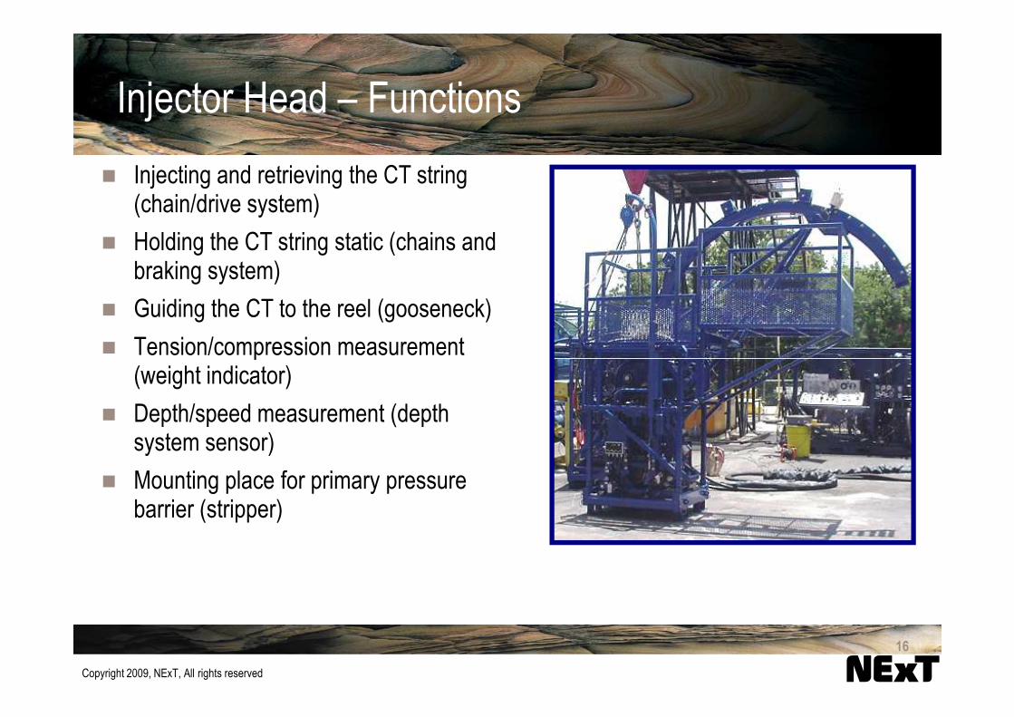
Injector Head – Functions
� Injecting and retrieving the CT string (chain/drive system)
� Holding the CT string static (chains and braking system)
� Guiding the CT to the reel (gooseneck)
� Tension/compression measurement
Copyright 2009, NExT, All rights reserved
� Tension/compression measurement (weight indicator)
� Depth/speed measurement (depth system sensor)
� Mounting place for primary pressure barrier (stripper)
16

Chain System – Hydra-Rig
Typical chain system includes:
1
2
Copyright 2009, NExT, All rights reserved
Typical chain system includes:
� Drive sprocket/system (1)
� Inside tensioners (2)
� Outside tensioners (3)
� Lower idling sprocket (4)
33
4
2
17

Injector Chains - HydraRig
Chain link pins
Copyright 2009, NExT, All rights reserved
Gripper blockRoller
bearing
Chain link plateand split pin
18
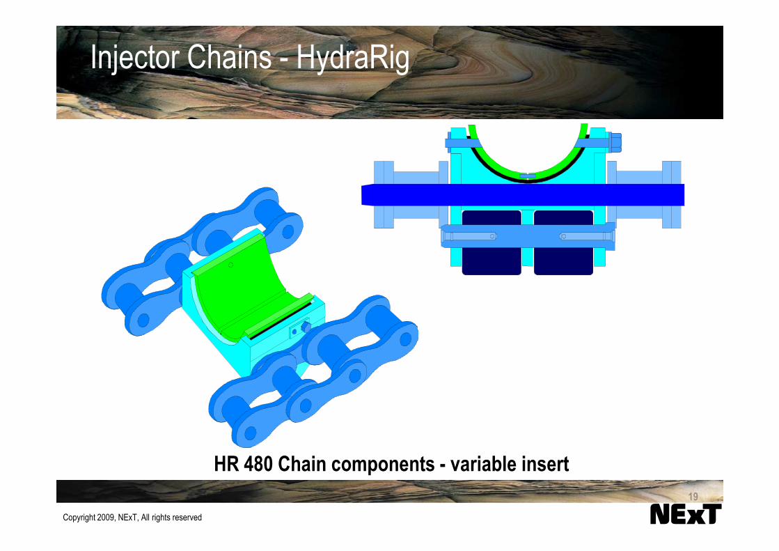
Injector Chains - HydraRig
Copyright 2009, NExT, All rights reserved
HR 480 Chain components - variable insert
19

Injector Chains - DRECO
Copyright 2009, NExT, All rights reserved
Blocks open Blocks closed
20

Injector Head – Typical Specifications
HR 260 HR 440 HR 480 HR-560
Capacities
Min. tubing size 1 1-1/4 1-1/2 1-1/2
Max. tubing size 1-3/4 2-3/8 3-1/2 2-3/8
Max. pulling force
- open loop(lbf.) 40,000 40,000 80,000 60,000
- closed loop(lbf.) 60,000 60,000 100,000 60,000
Copyright 2009, NExT, All rights reserved
- closed loop(lbf.) 60,000 60,000 100,000 60,000
Max. snubbing force (lbf.) 10,000 20,000 40,000 26,000
Max. running speed (fpm) 200 240 150 200
Dimensions
Length (in.) 53 55 64 55
Width (in.) 34 52 64 58
Height (in.) 65 80 109 89
Weight (lbm) 3,400 7,800 12,650 8,900
21

Injector head Guide Arch - Gooseneck
API Recommendations
Tubing Size Radius
(in.) (in.)
1-1/4 48 to 72
1-1/2 48 to 72
1-3/4 72 to 96
Copyright 2009, NExT, All rights reserved
1-3/4 72 to 96
2 72 to 96
2-3/8 90 to 120
2-7/8 90 to 120
3-1/2 96 to 120
22

Injector head Weight Indicator Sensor
Front sensor Rear sensor
Copyright 2009, NExT, All rights reserved
HR 480 dual weight indicator sensors
sensor
23
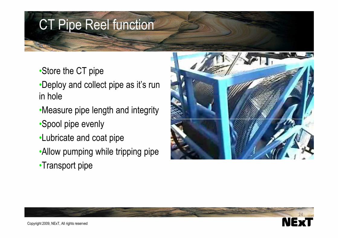
CT Pipe Reel function
•Store the CT pipe
•Deploy and collect pipe as it’s run
in hole
•Measure pipe length and integrity
•Spool pipe evenly
Copyright 2009, NExT, All rights reserved
•Spool pipe evenly
•Lubricate and coat pipe
•Allow pumping while tripping pipe
•Transport pipe
24
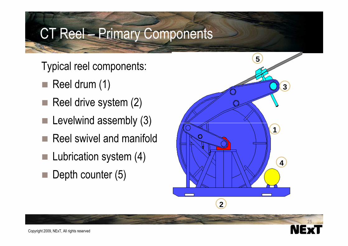
CT Reel – Primary Components
Typical reel components:
� Reel drum (1)
� Reel drive system (2)
� Levelwind assembly (3)
3
5
Copyright 2009, NExT, All rights reserved
� Levelwind assembly (3)
� Reel swivel and manifold
� Lubrication system (4)
� Depth counter (5)
1
2
4
25

CT Reel Manifold detail
Copyright 2009, NExT, All rights reserved
26

CT Reel – Completion pipe spooler
Copyright 2009, NExT, All rights reserved
Completion spool (3-1/2-in. CT) with custom built spooler27

CT Well Control Equipment
•Next Module
Copyright 2009, NExT, All rights reserved
28

CT Specialty Equipment
•Jacking Frames
Used to support the injector head
without a crane
•Towers
Used to support long lubricator rig
ups
Copyright 2009, NExT, All rights reserved
ups
•Lifting Frames
Used offshore on floating vessels
Motion compensator
29
Summary
Fit for purpose and operational constraints
Main components
- Hydraulic Power unit
- Control Cabin / Console
Copyright 2009, NExT, All rights reserved
- Control Cabin / Console
- Tubing Reel
- Injector Head
- Pressure control
- Lifting Equipment
30

Questions?
Copyright 2009, NExT, All rights reserved
31