01aintroduction with knobology.pptx.compressed · if the bursa communicates with the joint, ... ac...
TRANSCRIPT

1
Musculoskeletal Sonography Imaging Fundamentals and Systematic Scan Protocols
presented by Randy E. Moore , DC, RDMS RMSK
General Musculoskeletal Imaging, Inc.
No relevant financial relationships
2
knobology, a newly coined term that describes the relationship of instrument
controls to their function
Ultrasound… The New Standard of Care
Musculoskeletal sonography has become the �standard of care� in physical medicine for diagnostic exam and guided interventions.
Ultrasound has the unique and exceptional capability to reveal the �current physiologic state��of the
musculoskeletal anatomy. Placing the ultrasound probe on the patient
immediately displays
the entire physiologic spectrum from active inflammation to resolved fibrosis.
The pre-requisite to identifying pathology, and utilizing ultrasound for injection guidance, is developing the skill to
accurately and efficiently identify normal musculoskeletal anatomy on ultrasound examination. REM

3
Basic Concepts for MSK �Knobology�
Image Optimization
Image Orientation
3 Steps to Successful Imaging
Normal Musculoskeletal Anatomy
Artifacts in MSK
What kind of imaging is this anyway ? … (this is all the ultrasound physics I cover…don�t worry. ☺
Real-Time A series of frames or pictures displayed in rapid sequence
Pulse – Echo Sound pulses produced with time interval between to receive an echo
B – Mode �Brightness � Mode Proportional to amplitude of … returning echo

4
Which Probe ?? !
High Frequency For Superficial
Structures
Low Frequency For
Deeper Structures
7 - 15 MHZ Probes
3 – 5 MHZ Probes
Image Optimization
First !... Select the appropriate PRESET
Pre-programmed settings established to adjust the more intricate grayscale parameters of the image.
Relieves you of the burden of becoming
a sonographer .

5
Image Optimization �There�s so many buttons� !
Accurate and reproducible image production begins with initially visualizing the acoustic bony landmarks.
All navigation to… and identification of… anatomy
starts with the bright…hyperechoic cortical bone.
Image Optimization What to do if the boney landmarks are not seen 1. Increase the depth setting.
Typically occurs with larger patients or deep structures.

6
Image Optimization Stay focused…
2 . Move focal points to area of interest . This will be area of highest resolution.
Image Optimization Don�t Freq-out ! …
3. Decrease Probe Frequency Increased penetration…BUT…diminished resolution

7
Image Optimization
1. Increase the depth setting: Bony landmark 1st ! 2 . Focal points at area of interest: Highest Rez 3. Decrease Probe Frequency: Increase penetration
Image Optimization
Additional settings to consider. TGC�s aka…Depth Sensitive Controls
Increase or decrease brightness at specific depth

8
Image Optimization Additional settings to consider.
Overall Gain Control Increase or decrease brightness at all depths simultaneously
Make only minor changes
3 Steps to Successful Imaging The Solution…
A SYSTEMATIC… STANDARDIZED approach .
All newcomers to this imaging modality have the universal concern of how long it will take to
become proficient ,and how to read the images !
9
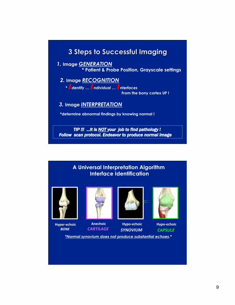
3 Steps to Successful Imaging
1. Image GENERATION
* Patient & Probe Position, Grayscale settings
2. Image RECOGNITION
* I dentify … I ndividual … I nterfaces From the bony cortex UP !
3. Image INTERPRETATION *determine abnormal findings by knowing normal !
TIP !!! …It is NOT your job to find pathology ! Follow scan protocol. Endeavor to produce normal image
*Normal synovium does not produce substantial echoes.*
Hyper-echoicBONE
AnechoicCARTILAGE
Hypo-echoic
SYNOVIUM Hypo-echoic
CAPSULE
A Universal Interpretation Algorithm Interface Identification

10
Image Orientation
Keeping It Straight Proximal or Distal ? Medial or Lateral ?
Long Axis/Longitudinal Views Left side of the image is CEPHALAD
Short Axis/Transverse Views Left side of the image is PATIENT RIGHT
Note: Use bony landmarks !
SAX
Image Orientation Probe placement relative to AXIAL spine
Proximal
Distal
LAX
Left Right
SAX

11
Image Orientation Long Axis/LAX
LONGITUDINAL Supra-patellar LONGITUDINAL Infra-Patellar
Patella Patella
Distal Proximal Distal Proximal
Image Orientation Short Axis/SAX
RIGHT SHOULDER SHORT AXIS
GT
SAX Left Right
SAX
Left Right Right

12
Image Orientation �One View… Is No View�
Accepted protocol is to obtain both long
and short axis views of most all musculoskeletal structures…
To completely visualize the anatomy
in multiple planes.
Normal Sonographic Appearance
Bony Cortex Hyaline Cartilage Skeletal Muscle
Ligaments Tendons
Peripheral Nerves Bursae
Fibro Cartilage

13
Sonographic �Signature� GRAYSCALE IMAGING
All musculoskeletal anatomy has a normal Grayscale appearance on ultrasound.
A �starting point� on a linear scale.
Up the scale
HYPER - echoic
Brighter
Down the scale
HYPO - echoic
Darker
Normal Sonographic Appearance Bony Cortex
Latin = external rind or bark Highly echogenic/bright
Smooth and Intact
14
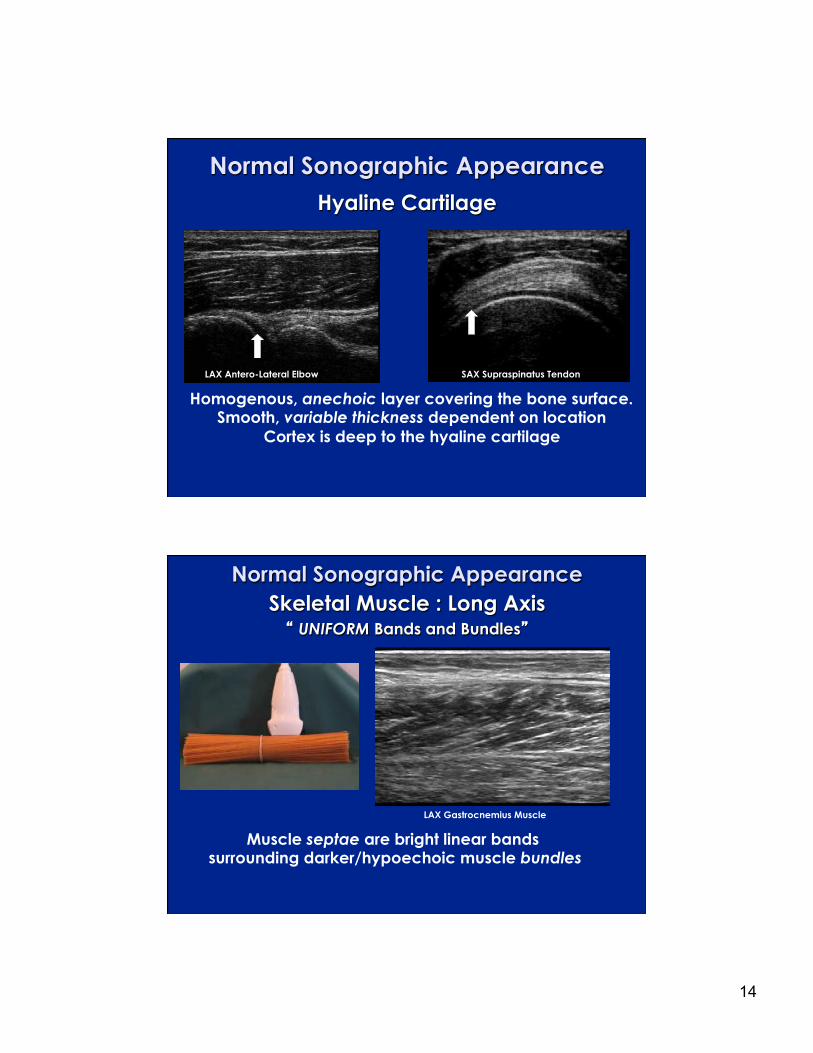
Normal Sonographic Appearance Hyaline Cartilage
Homogenous, anechoic layer covering the bone surface. Smooth, variable thickness dependent on location
Cortex is deep to the hyaline cartilage
LAX Antero-Lateral Elbow SAX Supraspinatus Tendon
Normal Sonographic Appearance Skeletal Muscle : Long Axis ��UNIFORM Bands and Bundles�
Muscle septae are bright linear bands surrounding darker/hypoechoic muscle bundles
LAX Gastrocnemius Muscle

15
Normal Sonographic Appearance
Skeletal Muscle : Short Axis
Muscle appears �speckled� echoes with bright curvilinear lines.
SAX Quadriceps Muscle
Normal Sonographic Appearance Ligaments : Long Axis
Attach Bone to Bone
Less collagen gives ligaments inconsistent brightness Use bony landmarks, and a hypoechoic
echogenicity of ligament vs. tendon
Tibia Fib
Tal
Femur
Medial Collateral Ligament
Anterior Talo-Fibular Ligament

16
Normal Sonographic Appearance Tendons : Long Axis
Parallel fibers are brighter than ligaments… due to collagen density. A consistent, bright appearance
*Hyperechoic…Fibrous…Echotexture
Tendons attach muscle to bone.
LAX Biceps Tendon
Normal Sonographic Appearance The Tendon �Footprint�
Two visual criteria for normal tendon attachment 1. Conformity 2. Uniformity
As the tendon tapers to a bony attachment. Collagen in Sharpey�s fibers mineralize, and penetrate into bone at a perpendicular angle to the ultrasound beam.
SAX Subscapularis Tendon

17
Normal Sonographic Appearance
The Tendon �Footprint� Two visual criteria for normal tendon attachment
1.Conformity of the tendon to the bone 2. Uniformity of the linear anechoic footprint
Normal Sonographic Appearance Tendons : Short Axis
WELL-DEFINED, hyper-echoic, with a dense pattern A �bristle-like� appearance
SAX Achilles Tendon SAX Patellar Tendon

18
Normal Sonographic Appearance Peripheral Nerve : Long Axis
Less bright/echogenic than tendons Parallel hyper-echoic lines with dark separations
Often adjacent to anechoic vascular bundle
�Railroad track� …or �collection of rods�
LAX Median Nerve
Normal Sonographic Appearance
Peripheral Nerve : Short Axis
Individual fibers present multiple, punctate foci . �Starry Night� or �Honeycomb�
appearance

19
Normal Sonographic Appearance
Bursae 1. A �POTENTIAL SPACE�, normally not visible
(With the exception of the Suprapatellar bursa)
2. Anechoic/black line, less than 2mm thick
3.Surrounded by hyper-echoic peribursal fat
4. If the bursa communicates with the joint,
it is compressible ,and fluid is forced into the joint.
Normal Sonographic Appearance
Bursae
A black or anechoic (without echoes) interface measuring less than 2mm is considered
�within normal limits�
Humerus
Acr
Humerus
Acr

20
Normal Sonographic Appearance Fibro cartilage
Triangular in appearance. Homogenous (no anechoic areas)
TMJ
Shoulder AC Joint
Hip Knee
TFCC Wrist
Artifacts in MSK
Anisotropy (An/Iso/Tropy)
An = Without
Iso = Equal
Tropy= Properties
To NOT have equal properties…characteristics… or appearances on…
ALL axes or orientations

21
Anisotropy is.. The property of being directionally dependent
Produced when the probe angle is NOT perpendicular with the structure being evaluated
Incorrect “angle of insonation” Primarily seen when scanning tendons, and
most common artifact in MSK ultrasound
Artifacts in MSK
Anisotropy is.. • The property of being directionally dependent
All depends on �how you look at it �
What do you see ?
A Frog ?... Or A Horse ? ?
Tip: Use only enough �toggle� and �heel-toe�
probe movement to minimize artifact
WITHOUT LOSING BONY LANDMARKS !

22
Artifacts in MSK Acoustic Shadowing
Foreign Body Localization Posterior Shadowing
Surgical Hardware �Comet tail�
Artifacts in MSK Reverberation
White Arrow = Multiple, equally spaced, linear echoes deep to needle
23
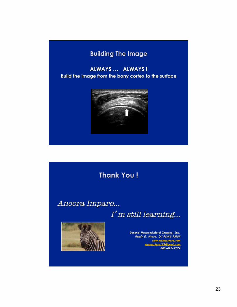
Building The Image
ALWAYS … ALWAYS ! Build the image from the bony cortex to the surface
Thank You !
Ancora Imparo…
I�m still learning…
General Musculoskeletal Imaging, Inc. Randy E. Moore, DC RDMS RMSK
www.mskmasters.com [email protected]
888-415-7774