0)12(&- 34(514)67&8+6)1*6#549:6&*,*2=
TRANSCRIPT

!"
!"#$$!%&'()*+,&-.!-&/&0)12(&-"
34(514)67&8+6)1*6#549:6&;*,*<4=&>2=<*#?@@:A<&B:64=&#$%&'"()*$'+$&'","-$)*$'+$""""./0-"123","4)23""""56/4"#0&$7$)","/-0&$7$)"
Abstract The Problem
Currently, there are three main issues with audio effect pedals that drastically limit their use and convenience—pedal price, computing power, and effect variability. The largest problems for the average at-home user are the cost and effect variability as it is extremely pricey to purchase multiple audio effect units and single units typically only contains one effect. The current market for at-home audio effects is defined by two different types of technology—individual pedals, also known as stomp boxes, and multi-effect boards. An individual pedal allows a user to take the audio output of either a guitar or another instrument and pass this as the input to the pedal. The effect pedal then processes the audio feed and passes out some form of modified signal for amplification. However, one of the major issues surrounding these pedals is that each pedal normally contains a single effect, which does not allow for a wide sound variety. The complexity of effects can be increased by hooking together several of the pedals to create an “effects-chain”, but this method becomes extremely pricey for an average user as each pedal costs $50 on the low end and can range into thousands of dollars depending on the complexity of the unit and its effect. Similarly, the second type of technology is an effects board, which allows the user to hook-up several different effects within a single unit, but once again they are extremely pricey and limited in the number of effects they can actually link together. Another major issue surrounding the audio-effects market is the complexity of an effect and the computing power required to implement the effect. It is necessary for real-time processing when dealing with audio effects so that the user is not able to detect any sort of delay between their playing and the output from the effect unit. Therefore, these pedals need to have fast processing ability and once again, this is one of the main reasons why the pedals and audio-effects boards are so expensive.
The Solution
The need for cheaper and more available audio-effect pedals is very relevant in pop culture and in order to address this problem, we would like to utilize the android market. By creating an application that allows user to simply use their tablet or phone as a multi-effect board processor we will be able to drastically cut-down on the price of these systems. There were over 150 million smart phones sold in the fourth quarter of 2011, and the Android platform dominated the market with 50.9% of the sales [1]. With the decreasing price of these devices, their sales will continue to grow and thus provide an extremely large market for this application. Therefore, we will be able utilize a device that many individuals already own, and thus make an extremely desirable application. The TapBoard project is brand new in relation to Android devices and there are currently no comparable products on the market for this operating system. Recently, applications have been

8"
developed for the iPhone and iPad that allow these devices to be turned into multi-effect pedals. An example of one of these applications is the AmpliTube iRig, which allows for amplification and effect processing of guitar and bass signals [2]. Again, this has not been performed on the Android platform and the TapBoard will be one of the first applications of its kind for this operating system.
GUI Design and Development
Initial Design
As with most applications on the market, the graphical user-interface is imperative for high
performance and overall user satisfaction. The design of our user-interface went through many
different versions and iterations throughout the course of the semester. The original
development began with a simple discussion of user-needs which ultimately led to the both the
final application design and data flow.
The overall goal of project was to create an application that allowed users to create a pedal-
effect train for guitars and basses. The original design centered on a user’s ability to choose
pedals, add them to the effect train, change pedal parameters, and select a processing button
allowing for real-time processing of the input signal.
"
Figure 1: Initial Whiteboard Design
9"
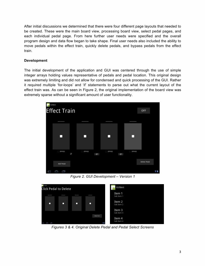
After initial discussions we determined that there were four different page layouts that needed to
be created. These were the main board view, processing board view, select pedal pages, and
each individual pedal page. From here further user needs were specified and the overall
program design and data flow began to take shape. Final user needs also included the ability to
move pedals within the effect train, quickly delete pedals, and bypass pedals from the effect
train.
Development
The initial development of the application and GUI was centered through the use of simple
integer arrays holding values representative of pedals and pedal location. This original design
was extremely limiting and did not allow for condensed and quick processing of the GUI. Rather
it required multiple ‘for-loops’ and ‘if’ statements to parse out what the current layout of the
effect train was. As can be seen in Figure 2, the original implementation of the board view was
extremely sparse without a significant amount of user functionality.
Figure 2. GUI Development – Version 1
Figures 3 & 4. Original Delete Pedal and Pedal Select Screens

:"
It is noticeable that initially the effect train has separate buttons for adding and deleting a pedal,
each of which led to completely different activities within the application. The original design
also lacked the ability to switch between pedals or bypass them from the current effect train.
Therefore, the initial display was extremely limiting in both functionality and appearance.
However, the initial design still held important value and information within it. It became
apparent that one of the major difficulties within the GUI design process is the passing of a large
number of parameters between each activity. We also realized that another difficult aspect of
this process was figuring out to seamlessly incorporate different sections of code, programmed
by different individuals, into the latest version of the application. Using this knowledge we set
out to design the next version of the program and GUI.
The final design can be seen Figures 5, 6, and 7 and implements a far more enjoyable user
experience.
"
Figure 5: Final Board View Design
&
Figure 6: Sample Pedal View

;"
"
Figure 7: Select Pedal Page
As noted above, one of the most difficult things about GUI implementation is the passing of
parameters between activities and making sure that the interface updates properly upon every
change. The new interface that was designed has many different images, buttons, seek bars,
and text that need to consistently be updated and changed as user interact with the application.
Therefore, we created a Pedal class, which would hold all of the necessary information relevant
to each pedal and then we could simply create an effect train array of pedals. Each pedal holds
the pedal name, its location within the array, its numerical value, its grey image name, a
Boolean of whether or not the pedal is bypassed, and the three different parameters of the
pedal. This was extremely useful in the design of the GUI as it allowed for a centralized location
for accessing the different aspects of each pedal. Therefore, we were able to simplify the
activities and create an application with only three main pages: the board view, pedal pages,
and select pedal page.
The update process for each GUI activity was optimized throughout many different versions.
Originally, each pedal had its function when it was called. However, this caused the code to be
extremely verbose and not very efficient. Therefore, as mentioned above, we added the
numerical pedal value to the pedal class, allowing each pedal to be passed and analyzed using
simple integer case statements. This allowed for greatly optimized code, as there were no
longer redundant functions calling the same code with slightly different parameters. In the final
version, the main method for updating the pedal array along with the bypass values and switch
pedal buttons utilized an update pedal function. This was called after all changes of the GUI and
traversed through the pedal array updating images and buttons accordingly. The final design
implemented many different layouts including linear layouts, relative layouts, scroll views, and
table row layouts.

<"
One final hurdle that needed to be overcome was combining the GUI and properly interacting
with the playing and processing threads. In order to do this, handler messages were passed
between the playing and thread with the main activity allowing for simultaneous updates of the
interface.
Future Work
There are many more things to be implemented within the final GUI design and development.
One of the simpler tasks will be to implement a splash screen with a product logo before the
application begins. Another important aspect of the interface will be to add a help screen
explaining all aspects of the program and how to use the different interfaces. On top this, a
settings page will be added allowing users to change the GUI to their liking (allowing for
messages to pop up before deleting a pedal, double click pedal deletions instead of long holds,
etc.). Similarly, we will need to implement a pedal train bank that allows users to store pedals
and effects that they like so that they will not need to create the train every time they open the
program. One final important step will be to adapt the GUI so that it properly displays on all
screen sizes.
Hardware Implementation
In order to simultaneously collect input from a guitar and send output to either speakers or an amplifier, we designed an adapter that utilized the four connections on the 1/8” audio jack on the device. Figure 8 shows the pinout of the device’s audio jack, along with a wiring diagram of our adapter and a picture of the prototype we built.
Pin Pin Name Description
1 Audio Channel Left
2 Audio Channel Right
3 Common Gnd
4 Mic & Control Input
Figure 8. Pin Assignment, Wiring Diagram, and Prototype

="
We used a male TRRS 1/8” jack to connect to the device, a female TRS 1/8” jack to connect the output speakers, and a female !” TRS jack to connect the guitar. The !” guitar input is wired to the mic pin on the 1/8” TRRS jack, and the left and right 1/8” speaker outputs on the TRS jack are wired to the left and right 1/8” outputs on the TRRS jack. Though this works as a solution, a pre-amp on the guitar input might provide a cleaner signal. We utilized a simple negative feedback op-amp preamp circuit as shown below in Figure 9. This is not currently a part of our hardware due to grounding issues between the preamp and tablet, but future work might include reincorporating the preamp in our setup.
Figure 9. Preamp circuit diagram
When we tried using USB audio input and output (described in the following section), we used a Behringer Guitar Link USB Interface with a built in preamp to connect our guitar to the device and output speakers. This was not included in our final demonstration.
Audio I/O The software implementation of audio input and output support consists of two main components, which are sampling the input from the guitar for processing, and writing samples of processed audio to be played. On the Android device there are potentially multiple ways to do this. When utilizing the audio jack for input and output, Android has classes that provide an API for accessing and outputting audio samples. Android also has classes that provide an interface for transferring data via USB connections. However, each of these methods of data transfer was problematic in our attempts to achieve pseudo real-time processing. Android’s limitations and our workarounds and solutions are described in the optimization section. Figure 10 shows the audio input, processing, and output signal flow as implemented in our project demonstration.

>"
Figure10. Audio I/O and processing flow
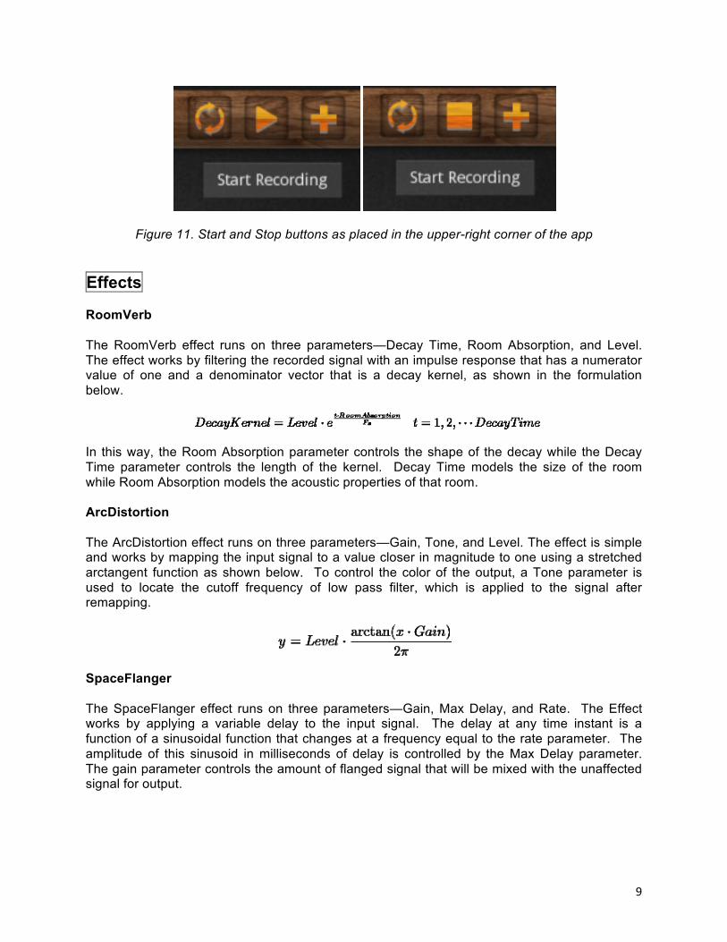
Our current implementation allows the user to record ten seconds of input, process that input with up to four effects, and then playback the processed signal as the output. We were unable to implement real-time processing due to Android constraints, which determined our current input and output approach. We use the AudioRecord Android class to sample the mono input signal at a sampling rate of 16 kHz in 16 bit encoding. The AudioRecord class cannot read input sample by sample, but must fill up a buffer of samples. The minimum size of this buffer is based on the sampling rate, encoding, and number of channels of input, and the minimum buffer size is one reason that pseudo real time processing is impossible on Android devices at this time. Because an entire buffer must be filled before we can access the raw audio data, the input latency has a theoretical minimum of the buffer size divided by the sampling rate. The minimum input latency on current Android devices ranges in the hundreds of milliseconds. The Android audio output class AudioTrack handles playback of raw audio samples. AudioTrack works in a similar way to AudioRecord, in that the programmer must specify the sampling rate, encoding, number of channels, and buffer size to output. We output audio using the same parameters as input: 16 kHz sampling rate, 16 bit encoding, and mono signal. The AudioTrack player introduces more latency into the system on the scale of hundreds of milliseconds. We use a multithreaded approach to recording, processing, and playing back recorded audio. When the user hits the record button, a new thread is created to record up to ten seconds of audio. This audio data is stored in a buffer of shorts, and the thread is closed when either the user stops the recording or ten seconds of recording has elapsed. When the user has selected pedals, the audio can be processed by hitting the process button. A new processing thread is created and blocks the user from hitting the play button while processing, and the thread is closed when processing completes. The user can then hit the play button, which creates a thread that plays back the audio and closes when the audio is finished playing. While playing, the play button becomes a stop button and the user can stop the audio by pressing it. Figure 11 shows the placement of these buttons in our app.
?"
Figure 11. Start and Stop buttons as placed in the upper-right corner of the app
Effects RoomVerb
The RoomVerb effect runs on three parameters—Decay Time, Room Absorption, and Level. The effect works by filtering the recorded signal with an impulse response that has a numerator value of one and a denominator vector that is a decay kernel, as shown in the formulation below.
In this way, the Room Absorption parameter controls the shape of the decay while the Decay Time parameter controls the length of the kernel. Decay Time models the size of the room while Room Absorption models the acoustic properties of that room.
ArcDistortion
The ArcDistortion effect runs on three parameters—Gain, Tone, and Level. The effect is simple and works by mapping the input signal to a value closer in magnitude to one using a stretched arctangent function as shown below. To control the color of the output, a Tone parameter is used to locate the cutoff frequency of low pass filter, which is applied to the signal after remapping.
SpaceFlanger
The SpaceFlanger effect runs on three parameters—Gain, Max Delay, and Rate. The Effect works by applying a variable delay to the input signal. The delay at any time instant is a function of a sinusoidal function that changes at a frequency equal to the rate parameter. The amplitude of this sinusoid in milliseconds of delay is controlled by the Max Delay parameter. The gain parameter controls the amount of flanged signal that will be mixed with the unaffected signal for output.

!@"
AutoWah
The AutoWah effect is a simple equalization effect with a single band-pass filter. It is used to boost around a specific center frequency, where the center frequency can either be a user-controlled parameter or determined mathematically from the level of the input signal. The center frequency can be swept across the frequency spectrum to create a vocal sound. We can implement this again using IIR band-pass filter design techniques. Since it will be difficult to play guitar and adjust the center frequency on an Android device at the same time, the center frequency will not be a user-controlled parameter. Instead, it will be controlled by a low pass version of the input signal. The intensity (or boost of the filter) will be a user-controlled parameter. TapDelay
The TapDelay effect runs on three parameters—Delay Time, Gain, and Level. The effect works by applying an IIR filter of an order based on the Delay Time parameter in samples. The impulse response of the IIR filter used has a numerator coefficient of one and a denominator vector that is made of a single impulse of height one for the zero-ith coefficient and a single impulse of height equal to the Gain parameter for the final coefficient. A block diagram for the signal can be seen in Figure 12.
Figure 12. Block Diagram for the TapDelay effect
Optimization Audio Input/Output We tried multiple methods of obtaining audio input and output in our attempts to create a virtually real time system. After determining that the latency in Android’s audio I/O API’s was too high to simulate real time, we tried to access the audio hardware directly by using the PortAudio C library. Since this would be native code accessing hardware directly instead of running on a virtual machine, we hoped that we could minimize the input and output latencies to five or fewer milliseconds in each direction. In theory this still might work, but we were unable to compile the PortAudio library files to be compatible with Android. When trying to compile using the PortAudio libraries, the NDK builder would return an error stating that the library file (libportaudio.a) was incompatible. Research has suggested there might be a way to compile PortAudio for the ARM processors used by Android devices instead of x86, but no conclusive evidence or testing was found and we were unable to successfully compile it. Next, we discovered an article by an employee from Collabora who integrated PulseAudio, a sound server, into the Android operating system. PulseAudio controls audio data communication between the Linux kernel and applications, as shown in Figure 13. According to his results, the change reduced the latency in audio output from 176 to 20 milliseconds. Due to the facts that none of us have experience in rooting a device, re-imaging an operating system,

!!"
or dealing with software just above the kernel level, and 20 milliseconds in one direction is still high for our application, we decided not to implement this solution.
Figure 13. PulseAudio layer
Another potential solution is to use a USB interface for guitar input and output. We purchased a Behringer Guitar Link USB Interface, which has a built in guitar preamp for easily connecting a guitar to a computer. Android includes APIs for USB connection and transfer, allowing the device to act as a USB host as shown in Figure 14. This involves instantiating a UsbManager, obtaining the device information using the UsbDevice class, setting up the appropriate UsbInterface, and setting up the correct UsbEndpoint, which is used to communicate with the USB interface. There are four types of USB endpoints, and one of them communicates isochronously, meaning at fixed intervals. Android does not provide support for isochronous USB connections using the java APIs, meaning we could not successfully communicate between the tablet and the USB interface. We plan to use native code to implement isochronous USB communication in the near future.
Figure 14. Android device as USB host
Effect Algorithms
The first step taken toward optimization was the creation of a java-based filter function that operates similar to the filter function implemented in MATLAB. The inputs to the function are an array of a coefficients, an array of b coefficients, and an input vector. The function returns the output vector and performs the operations in a Direct Form II fashion, illustrated in Figure 15.

!8"
Figure 15. Direct Form II Filter
The next round of optimization was done in an effect specific fashion. We were able to optimize both the RoomVerb and TapDelay effects such that their runtimes were reduced by well over a factor of two. In the original carnation of the TapDelay effect, we used IIR filter with a single b coefficient of one and an a vector that contained two impulses—a value of one for the first value of the vector and a value equal to the gain factor for the second impulse. This required us to compute the convolution of the entire recorded signal and the two impulse echo kernel, which has a length of echo time multiplied by the sample rate. Since most of the multiplies and sums that are done using this method are done with zero, we were able to replace this bulky operation with a single line of code:
output[i] = input[i] + GAIN * output[i-delay_time]
This method reduces the computational complexity from O(recorded signal length * kernel length) to O(recorded signal length). For the RoomVerb effect the method of optimization is much more ad hoc. Since the RoomVerb involves the convolution of a very long vector with the entire piece, we were able to reduce the computation by skipping every other sample of the impulse response and only summing over even samples. This results in a reduction in complexity by a factor of two.
Feedback
We received generally positive feedback from students and faculty at both our in-class presentation and public demonstration. The graphics and user interface were described as “easy to use,” and “realistic.” People both familiar with guitar and new to guitar commented that the processed sounds were not as good as some high quality effect pedals, but were still good enough to be used for practice and some live performances. One criticism was we had to process the audio to play it back, even if not applying effects, but we have fixed this. We received feedback from Professor Stern regarding the reverb pedal processing time. He helped us figure out a new way to compute the output using difference equations instead of room response convolution. We plan to implement this new algorithm in the near future.

!9"
Schedule
Mark Loh
Adam Kriegel
Kevin Elfenbein
March 4 – March 18 • Define Graphical User Interface specifications
• Effect design • Matlab
Implementations
• Effect design • Audio I/O using
Android APIs
March 18 – April 1 • GUI software • Communicate with
Jordan regarding graphics
• Matlab Implementations
• Test effects and modify parameters
• Matlab implementations
• Compile and run PortAudio on Android
April 1 – April 15 • GUI software • Incorporate
graphics
• Port effects to Java implementations
• Research Audio I/O USB devices
• PulseAudio for Android research
• USB guitar interface I/O
April 15 – April 29 • Finish GUI software
• Test GUI • Audio I/O
hardware • Final Presentation
• Finish java effects • Test effects using
voice and guitar • Final Presentation
• Non real-time audio I/O using Android APIs
• Audio I/O hardware
• Final Presentation

!:"
References
1. Brownlow, Mark. "Smartphone Sales and Statistics." Email Marketing Reports. Feb. 2012. Web. 19 Feb. 2012. <http://www.email-marketing-reports.com/wireless-mobile/smartphone-statistics.htm>.
2. "AmpliTube IRig - Apple Store (U.S.)." Official Apple Store. Apple, 2012. Web. 19 Feb. 2012. <http://store.apple.com/us/product/H2169VC/A>.
3. Source Audio Technical Papers a. Tomarakos, John, and Dan Ledger. "Using The Low Cost, High Performance
ADSP-21065L Digital Signal Processor For Digital Audio Applications." Analog Devices DSP Applications (1998).
b. Chidlaw, Robert. “Multiwave Distortion Technology.” Source Audio LLC. 4. Caputi, Mauro J. "Developing Real-Time Digital Audio Effects for Electric Guitar." IEEE.
IEEE, 1998. Web. 19 Feb. 2012. <http://ewh.ieee.org/soc/es/Nov1998/01/BEGIN.HTM>. 5. "GM Arts - Guitar Effects." GM Arts - Home. Web. 19 Feb. 2012.
<http://www.gmarts.org/index.php?go=221>. 6. Dattorro, Jon. “Effect Design Part 1: Reverberator and Other Filters.” CCRMA, Stanford
University. 7. Dattorro, Jon. “Effect Design Part 2: Delay Line Modulation and Chorus.” CCRMA,
Stanford University. 8. Smith, Julius. “Making Virtual Electric Guitars and Associated Effects Using Faust.”
REALSIMPLE Project. CCRMA at Stanford, 2010. Web. 09 May 2012. <https://ccrma.stanford.edu/realsimple/faust_strings/Adding_Wah_Pedal.html>
9. “Digital Audio Effects.” Lecture, CM0268. Cardiff University. Web. 09 May 2012. <http://www.cs.cf.ac.uk/Dave/CM0268/PDF/10_CM0268_Audio_FX.pdf>
10. Raghavan, Arun. “PulseAudio vs. AudioFlinger: Fight!” Collabora, 2012. Web. 09 May 2012. <http://arunraghavan.net/2012/01/pulseaudio-vs-audioflinger-fight/>
11. PortAudio. Web. 09 May 2012. <http://www.portaudio.com/> 12. "Android Developers." Android Developers. Google, 2012. Web. 09 May 2012.
<http://developer.android.com/index.html>. 13. "Creating Objects." The Java Tutorials. Oracle, 2012. Web. 09 May 2012.
<http://docs.oracle.com/javase/tutorial/java/javaOO/objectcreation.html>. 14. Martin. "How To: Create a Splash Screen." Android Development. 14 Oct. 2009. Web.
09 May 2012. <http://www.droidnova.com/how-to-create-a-splash-screen,561.html>. 15. Metter, Koa. "Create a Custom-Styled UI Slider (SeekBar) in Android." What's Brewing
in the Mobile World? Mokasocial, 17 Feb. 2011. Web. 09 May 2012. <http://www.mokasocial.com/2011/02/create-a-custom-styled-ui-slider-seekbar-in-android/>.
16. "Stack Overflow Questions." Stack Overflow. Web. 2012. <http://stackoverflow.com/questions>.