01 rn20081en12gln1 radio resource administration mo
DESCRIPTION
NSN RadioTRANSCRIPT

Template for NTC Training documents written with Word 97
Training DocumentBSSPAR 12: Chapter 01
V.3 © Nokia Siemens Networks 1 (44)

Radio Resource Administration
The information in this document is subject to change without notice and describes only the product defined in the introduction of this documentation. This document is intended for the use of Nokia Networks' customers only for the purposes of the agreement under which the document is submitted, and no part of it may be reproduced or transmitted in any form or means without the prior written permission of Nokia Networks. The document has been prepared to be used by professional and properly trained personnel, and the customer assumes full responsibility when using it. Nokia Networks welcomes customer comments as part of the process of continuous development and improvement of the documentation.
The information or statements given in this document concerning the suitability, capacity, or performance of the mentioned hardware or software products cannot be considered binding but shall be defined in the agreement made between Nokia Networks and the customer. However, Nokia Networks has made all reasonable efforts to ensure that the instructions contained in the document are adequate and free of material errors and omissions. Nokia Networks will, if necessary, explain issues which may not be covered by the document.
Nokia Networks' liability for any errors in the document is limited to the documentary correction of errors. Nokia Networks WILL NOT BE RESPONSIBLE IN ANY EVENT FOR ERRORS IN THIS DOCUMENT OR FOR ANY DAMAGES, INCIDENTAL OR CONSEQUENTIAL (INCLUDING MONETARY LOSSES), that might arise from the use of this document or the information in it.
This document and the product it describes are considered protected by copyright according to the applicable laws.
NOKIA logo is a registered trademark of Nokia Corporation.
Other product names mentioned in this document may be trademarks of their respective companies, and they are mentioned for identification purposes only.
Copyright © Nokia Networks Oy 2012. All rights reserved.
2 (44) © Nokia Siemens Networks

Radio Resource Administration
Contents
1 Radio Resource Administration..................................41.1 Module Objectives..........................................................41.2 Fundamental Parameters...............................................41.3 Radio Channel Configuration..........................................41.3.1 GSM Frame Structure.....................................................41.3.2 GSM Channels................................................................61.3.3 Signalling Capacity Estimation......................................251.4 Extended Cell................................................................281.4.1 Implementation.............................................................281.4.2 Cell Selection and Handover........................................301.4.3 Base Station Identity Code...........................................311.4.4 Training Sequence Code..............................................321.5 Frequency Administration.............................................331.5.1 Overview.......................................................................331.5.2 Base Band Hopping......................................................371.5.3 RF Hopping...................................................................381.5.4 Change of Frequency Plan...........................................42
© Nokia Siemens Networks 3 (44)
Radio Resource Administration
1 Radio Resource Administration
4.2 Module Objectives
At the end of the module the participant will be able to:
Give an overview about the TDMA frame structure
Describe the logical channels, their mapping to TDMA frames and their parameters
Demonstrate, how the signalling capacity effect the mapping of the logical channels
Give an overview about the use of extended cells
Describe the purpose of the Base Station Identity Code and the Training Sequence Code
Explain the use of FDMA and frequency reuse
Discuss the parameter settings required for base band and RF frequency hopping
4.3 Fundamental Parameters
4.4 Radio Channel Configuration
4.4.1 GSM Frame Structure
4.4.1.1 TDMA Frame Structure
As mentioned already, GSM uses as multiple access technology not only FDMA, but also TDMA, i.e. physical channels are separated from each other by time. This means that for the radio path between the antennas of a MS and a BTS, every channel has a specific time period on a frequency during which it can act. The transmitters generate electromagnetic impulses – called bursts – and modulate the user data only at a dedicated time slot period. Each burst lasts 0.577 ms (exactly 15/26 ms) and thus eight bursts last 4.615 ms. there are different kinds
4 (44) © Nokia Siemens Networks

Radio Resource Administration
of bursts for different purposes. The contents of the burst can vary, but the time duration of each one is always the same.
In GSM, each 200 kHz frequency carrier is organised in eight TDMA channels, which are either user as traffic channels or as signalling channels. These eight channels have their own "slots" related to the time for transmitting or receiving data. Therefore, every physical channel has the „right“to act every eighth time slot. Such an organisation of eight time slots is called TDMA frame. This is the smallest and the basic unit of the TDMA frame structure. It is shown by Fig. 1-1.
Fig. 1-1: Basic TDMA Structure
4.4.1.2 Multi, Hyper and Super Frame
Other higher level frames are needed for the GSM channel organisation. With the TDMA frame alone, it would be very difficult and not efficient to map logical channels to physical ones. To allow a more complex organisation of data transmission on physical channels, larger frame structures have been introduced.
Multi frames: Three different types of multiframes are defined.26 multi frames contains 26 TDMA frames. Therefore it lasts 120 ms. 26 multi frames carry TCH, SACCH and FACCH data. 51-multiframes comprise 51 TDMA frames. They are used to carry logical channels for signalling and control, i.e. BCH, CCCH, SDCCH, and SACCH. The duration of such a multi frame is 235 ms. 52-multiframes have been specified for GPRS. GPRS is discussed by a separate chapter.
Super frames: 51 multi frames and 26 multi frames start at the same TDMA frame only every 51 * 26 TDMA frame period, i.e. every 6.12 s. This defines a super frame.
© Nokia Siemens Networks 5 (44)

Radio Resource Administration
Hyper frames: This is the longest recurrent time period structure in GSM. It is a multiple of 2048 super frames, and thus repeats itself only after 3 h 28 min 53.76 s. The TDMA frame number is linked with the hyper frame. The first TDMA frame of a hyper frame has number zero. With each new TDMA frame, the TDMA frame number is incremented by one. The last TDMA frame of a hyper frame has number 2715647. Then a new hyper frame begins, and the first TDMA frame is numbered again with zero. As mentioned already, the TDMA frame number is used for frequency hopping algorithms. Furthermore it is an input for the ciphering algorithm on the radio interface. The higher level frames are summarized by Fig. 1-2.
Fig. 1-2: Multi, super and hyper frame
4.4.2 GSM Channels
Two types of channels have been defined in GSM, logical and physical ones.
Logical Channels: A wide range of signalling information and data has to be exchanged between the MS and the BSS. Signalling and control is required in different situations. For example, some signalling messages are used to control a dedicated radio link between the MS and the BSS. Timing advance data, power control commands, measurement reports etc. are transmitted for this purpose. These signalling and control messages are transmitted over one logical channel, which is called Slow Associated Control Channel. Another logical channel is used to transport „first contact “information and allows the MS to access the mobile communication network. This logical channel is called Random Access
6 (44) © Nokia Siemens Networks
Radio Resource Administration
Channel. A set of logical channels has been defined in GSM. Each logical channel is used to transport a well defined type of information.
Physical Channels: Physical channels provide the means to transport higher layer information. In GSM physical channels are characterised among others by the absolute radio frequency carrier number (ARFCN), the timeslot number (TS), and the frequency hopping algorithm.
Logical Channels are mapped into physical channels, i.e. a single physical channel can be used to transport the information bits of several logical channel. The GSM standard describes how the mapping of logical channel information into physical channels is done. An overview about the GSM channel organisation is given by Fig. 1-3.
Fig. 1-3: GSM channel organisation
4.4.2.1 Logical Channels
In GSM there are different types of logical channels, which are mapped into physical channels in the radio path. Logical channels comprise of common channels and dedicated channels. Common channels are those that are used for broadcasting different information to MSs and setting up of signalling channels between the MSC/VLR and the MS. Common control channels are divided into Broadcast Channels (BCH) and Common Control Channels (CCCH). Signalling channels between the MSC/VLR and a specific MS are dedicated control channels
© Nokia Siemens Networks 7 (44)

Radio Resource Administration
(DCCH). Traffic channels (TCH) are also dedicated ones as each channel is dedicated to one user only to carry speech or data.
Not all currently specified logical channels are discussed here, but only those nowadays used in GSM for circuit switched services.
Broadcast Channels
Broadcast channels are downlink point-to-multipoint channels. They contain general information about the network and the broadcasting cell. There are four types of broadcast channels:
1) Frequency Correction Channel (FCCH)
The FCCH enables a MS to find the carrier that contains the broadcast transmission. A specific burst has been developed for the FCCH, called FCCH burst. The MS scans for this burst after it has been switched on since it has no information which frequency to use.
2) Synchronisation Channel (SCH)
The SCH is used for time synchronisation. The MS learns when exactly modulated bits arrive at its receiver. This is achieved by a burst with a long training sequence, which has explicitly designed for the SCH. The SCH also contains the Base Station Identity Code BSIC (see section 4.3 Fundamental Parameters) and a reduced TDMA frame number. The BSIC is needed to identify the cell, which signal strength is measured by the mobile. The TDMA frame number is required for speech encryption purpose.
3) Broadcast Control Channel (BCCH)
The BCCH contains detailed network and cell specific information such as:
a) Frequencies used in the particular cell and neighbouring cells.
b) Frequency hopping sequence to be used by the MS.
c) Channel combination. This informs the MS about the mapping method used in the particular cell. The possible methods are discussed in the following.
d) Paging groups. Normally in one cell, there is more than one paging channel. To prevent a MS from listening to all these for a paging message, the paging channels are divided in such a way that only a group of MSs Listen to a particular paging channel. These are referred to as paging groups. Paging is discussed further in the following.
e) Information on surrounding cells. A MS has to know what are the cells surrounding the present cell and what frequencies are being broadcast on them. This is necessary if e.g. the user initiates a conversation in the current cell, and then decides to move on. The MS
8 (44) © Nokia Siemens Networks

Radio Resource Administration
has to measure the signal strength and quality of the surrounding cells and to report this information to the BSC.
4) Cell Broadcast Channel (CBCH)
This channel is used to broadcast user information, e.g. about traffic, weather etc., by short messages. It is not used for signalling.
Common Control Channels
Common Control Channels comprise the second set of logical channels. They are used to set up a point to point connection. There are three types of common control channels:
1) Paging Channel (PCH)
The PCH is a downlink channel, which is broadcast by a BTS in the case of a mobile terminated call.
2) Random Access Channel (RACH)
The RACH is in use in the uplink direction only and the first point to point channel of the common control channels. It is used by the MS in order to initiate a transaction, or for a response to a PCH.
3) Access Grant Channel (AGCH)
The AGCH is the answer to the RACH. It is used to assign to a MS a Stand-alone Dedicated Control Channel (SDCCH). It is a downlink point to point channel.
4) Notification Channel (NCH)
This logical channel is used in the downlink direction only. It informs MSs about voice group and voice broadcast calls.
Dedicated Control Channels
Dedicated Control Channels compose the third group of channels. Again, there are three dedicated channels. They are used for call set up, sending measurement reports and handover. They all are bi-directional and point-to-point channels.
1) Stand Alone Dedicated Control Channel (SDCCH)
The SDCCH is used for system signalling: call set up, authentication, location update, and assignment of traffic channels and transmission of short messages.
2) Slow Associated Control Channel (SACCH)
A SACCH is associated with each SDCCH and traffic channel (TCH). It transmits measurement reports and is also used for power control, time alignment, and in some cases to transmit short messages.
3)
© Nokia Siemens Networks 9 (44)

Radio Resource Administration
Fast Associated Control Channel (FACCH)
The FACCH is used for additional signalling on traffic channel resources, for instance when a handover is required. Hereby it replaces 20 ms of speech and therefore it is said to work in "frame stealing" mode. A summary about all logical channels is given by Fig. 1-4.
Fig. 1-4: Logical channels
10 (44) © Nokia Siemens Networks

Radio Resource Administration
Traffic Channels
Traffic Channels are logical channels that transfer user speech or data, which can be either in the form of Half Rate HR (5.6 kbits/s), Full Rate FR (13 kbits/s), or Enhanced Full Rate EFR (12.2 kbit/s) traffic. The speech coding in EFR is different to that used for normal full rate traffic. It gives better speech quality at about the same bit rate as normal full rate coding. Traffic channels can transmit both speech and data and are bi-directional channels.
Adaptive MultiMate AMR speech coding has been defined in the GSM/EDGE radio access network both for full rate traffic channels (with data rates ranging from 12.2 down to 4.75 kbit/s) and half rate traffic channels (with data rates ranging from 7.95 down to 4.75 kbit/s). Please note, that traffic channels associated with speech codec’s can only be used, if both MS and network support the speech codec. The different kinds of speech coding are discussed in a separate chapter.
Also data transmission is possible on traffic channels. Traffic channels allow data transmission rates of 9.6, 4.8 and 2.4 kbit/s. But what is e.g. the difference between TCH/F2.4 and TCH/H2.4? In both cases, the net data rate is 2.4 kbit/s, i.e. 4.8 kbit/s user data is transmitted. But the channel coding is different for the two channels. Channel coding includes the addition of redundancy. In the full rate channel TCH/F2.4, more redundancy is added than in the half rate channel TCH/H.2.4. In the full rate channel, the data rate including channel coding is 22.8 kbit/s, i.e. for each user bit 5 redundancy bits are added. In the TCH/H2.4, the data rate including channel coding is 11.4 kbit/s. The traffic channels are summarized by Fig. 1-5.
© Nokia Siemens Networks 11 (44)

Radio Resource Administration
4.4.2.2 Fig. 1-5: Traffic channels Physical Channel Configuration
Signalling and control information as well as user data have to be transmitted via the radio interface. The channel organisation describes, how the content of different logical channels is organised (= mapped) on physical channel resources. The channel organisation is described with the multi frames.
Traffic Channel Configuration
Traffic channels (TCH) can be only found on 26 multi frames. Their organisation can be seen in Fig. 1-6. In the upper part, you can see the transmission of a full rate traffic channel, such as TCH/FR. Within a 26 multi frame, the content of the traffic channel is transmitted always except in TDMA frame 13 and 26. In TDMA frame 13, the content of a Slow Associated Control Channel SACCH/T is transmitted (the designation SACCH/T is used for SACCH content transmitted on a TCH). This channel is required for radio link management, and it carries timing advance and power control information in the downlink direction. In the uplink direction, it is used to transmit measurement reports. One SACCH/T message is transmitted via four normal bursts. As one SACCH/T burst can be transmitted in one 26 multi frame, four 26 multi frames (= 480 s) are required to send one SACCH/T message from transmitter to receiver. If additional signalling is required – for instance during a handover process – FACCH signalling can be done on TCH
12 (44) © Nokia Siemens Networks

Radio Resource Administration
resources. The last TDMA frame within a 26 multi frame is set to „idle“. No transmission takes place here, and the MS has enough time to decode the BSIC of one of the neighbouring cells.
In the lower part of the figure, you can see the channel organisation when half rate traffic channels are used. As can be seen, for one user data transmission takes place in every second TDMA frame only. Half rate allows more subscribers to be served in one cell, but with a lower data rate and quality.
Fig. 1-6: Traffic channel mapping
Signalling Channel Configuration
Signalling and control channel information is organised on 51 multi frames. Only the SACCH/T and the FACCH are located on 26 multi frames. The following channel organisations on a 51 multi frame have been specified.
1) BCCH + SDCCH/4 + SACCH/C4
2) BCCH + CCCH/9 and SDCCH/8 + SACCH/C4
3) BCCH + SDCCH/4 + SACCH/C4 and SDCCH/8 + SACCH/C4
1) BCCH + SDCCH/4 + SACCH/C4
© Nokia Siemens Networks 13 (44)

Radio Resource Administration
In Fig. 1-7 the BCCH + SDCCH/4 + SACCH/C4 channel combination can be seen. There is a difference between uplink and downlink. In the downlink direction, a time multiplexing of FCCH, SCH, BCCH, CCCH data etc. takes place. If a MS request channel resources, the BSC can allocate dedicated signalling resources to it. Up to four MS can be served simultaneously. Four TDMA frames are used to send SDCCH messages to one MS and to transmit SDCCH messages to the network (in the uplink direction). The physical link is managed with the help of the SACCH/C (the designation SACCH/C is used for SACCH content transmitted on a control channel). Four consecutive TDMA frames are used to transmit SACCH messages. There are only 8 TDMA frames available for SACCH data transfer, i.e. only two MSs can get radio link management messages by one 51 multi frame. In order to serve up to 4 dedicated signalling connections, a SACCH radio block can be used by a MS only every second 51 multi frame. In the uplink direction it is also specified, which resources can be used by a MS for random access.
The channel combination is used for cells with a maximum of up to 2 TRXs. The signalling information is transmitted on timeslot 0 of every TDMA frame.
Fig. 1-7: Signalling channel mapping (BCCH + SDCCH/4 + SACCH/C4)
14 (44) © Nokia Siemens Networks

Radio Resource Administration
2) BCCH + CCCH/9 and SDCCH/8 + SACCH/C4
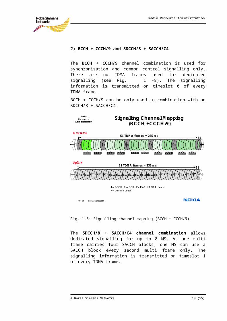
The BCCH + CCCH/9 channel combination is used for synchronisation and common control signalling only. There are no TDMA frames used for dedicated signalling (see Fig. 1-8). The signalling information is transmitted on timeslot 0 of every TDMA frame.
BCCH + CCCH/9 can be only used in combination with an SDCCH/8 + SACCH/C4.
Fig. 1-8: Signalling channel mapping (BCCH + CCCH/9)
The SDCCH/8 + SACCH/C4 channel combination allows dedicated signalling for up to 8 MS. As one multi frame carries four SACCH blocks, one MS can use a SACCH block every second multi frame only. The signalling information is transmitted on timeslot 1 of every TDMA frame.
© Nokia Siemens Networks 15 (44)

Radio Resource Administration
Fig. 1-9: Signalling channel mapping (SDCCH/8 + SACCH/C4)
The combination BCCH + CCCH/9 and SDCCH/8 + SACCH/C4 requires 3 to 4 TRXs in the cell. It is called also separate structure.
3) BCCH + SDCCH/4 + SACCH/C4 and SDCCH/8 + SACCH/C4
This is a combination of 1) and the second part of 2).
BCCH + SDCCH/4 + SACCH/C4 are transmitted on timeslot 0, SDCCH/8 + SACCH/C4 again on time slot 1 of every TDMA frame. This combination is called hybrid channel structure and requires 3 to 4 TRXs in the cell.
A carrier called C0 is used to transmit a burst in every timeslot in the downlink direction. This allows a MS to find a cell when performing level measurements. Dummy bursts are transmitted, if there is no data to be send. In timeslot 0 of the C0, there must be either the channel combination BCCH + SDCCH/4 + SACCH/C4 or BCCH + CCCH/9. In other words, only in the first timeslot of a TDMA frame of the C0, FCCH, SCH and BCCH channels can be found. If the hybrid or separate channel structure is used, on timeslot 1 of the C0 there is the SDCCH/8 + SACCH/C4 channel combination.
16 (44) © Nokia Siemens Networks

Radio Resource Administration
Setting of the channel configuration
The channel configuration used for a TDMA timeslot is set by the parameter channel Type (CH0-CH7)(RTSL)(TCHF,TCHH,TCHD, ERACH,NOTUSED,SDCCH,MBCCH,MBCCHC,MBCCB,SDCCB,MPBCCH)(TCHF). The possible settings are listed by .
Fig. 1-10: Channel mapping (parameter setting)
Dynamic SDCCH Allocation
This optional feature allows using free TCHs for SDCCH traffic, if all static SDCCHs are occupied. In this case the system will turn a TSL configured for TCH use into a SDCCH TSL. When these additional SDCCH radio resources are no longer needed, they are immediately configured back for TCH use. Thus the maximum number of TCHs available for user traffic is depending on the actual need for SDCCH resources.
Dynamic SDCCH allocation is useful especially, if signalling traffic dominates the network. This can happen, e.g. at airports, where location updates can produce sudden short time SDCCH traffic peaks. This can now be handled without any need to configure extra permanent SDCCH capacity.
The SDCCH capacity required depends on many factors, e.g. the number of cells per location area. With increasing number less location updates take place, i.e. the SDCCH traffic goes down. When doing SDCCH capacity estimations, one must consider also the limited
© Nokia Siemens Networks 17 (44)

Radio Resource Administration
capability of the BSC signalling unit, which can handle a maximum of 384 SDCCHs. typical examples are discussed in the following.
Dynamic SDCCH resources can be configured only when a SDCCH is allocated for immediate assignment. Therefore during a SDCCH handover this is not allowed. Already existing dynamic SDCCHs, however, can be used in handovers. For the allocation of dynamic SDCCHs the following restrictions have to be taken into account.
The SDCCH is configured to a TRX, which has least number of SDCCHs or no SDCCHs yet at all.
The SDCCH is configured to a TRX, which has least number of occupied channels.
If between different types of TCHs must be selected, then the preference order is: first HR, then FR and finally DR TCH.
In intelligent underlay overlay networks, dynamic SDCCHs are supported by regular TRXs only. A timeslot of least uplink interference should be selected.
If FACCH call set up is activated (discussed in the following), in situations of SDCCH congestion, the MS can be assigned to a TCH from the CCCH at the time of immediate assignment. If both FACCH call set up and dynamic SDCCH allocation are activated, usually the latter has higher priority. FACCH call set up is performed, however, in the following cases.
The configuration of any dynamic SDCCH resource in the BTS is not possible
All TCH resources of the BTS are just in use
Dynamic SDCCH allocation is summarized by .
18 (44) © Nokia Siemens Networks
Radio Resource Administration
Fig. 1-11: Dynamic SDCCH allocation
FACCH Call Set Up
This procedure can be used as an alternative to dynamic SDCCH allocation. If the MS requests a TCH, but no SDCCH is available, the MS is assigned a TCH from the CCCH instead of an SDCCH. For call set up signalling, the FACCH is used instead of the SDCCH.
For FACCH call set the parameter newEstabCausesSupport (NECI)(SEG)(Y/N)(N) has to be set to Y. Additionally, one must enabled FACCH ordinary call set up, FACCH emergency call set up and FACCH call reestablishment by setting the parameters ordinaryCallOnFacch (EOF)(BSC)(Y/N)(N), emerCallOnFacch (EEF) (BSC)(Y/N)(N) and reestablishOnFacch (ERF)(BSC)(Y/N)(N) to Y. Also the FACH Call Set Up can be enabled for certain establishment causes only. FACCH call set up is summarized by Fig. 1-12.
© Nokia Siemens Networks 19 (44)

Radio Resource Administration
Fig. 1-12: FACCH call set up
20 (44) © Nokia Siemens Networks

Radio Resource Administration
4.4.2.3 Logical Channel Parameters
To configure the PCH, RACH and AGCH, further parameters must be set.
PCH Parameters
Paging is performed when an incoming call or short message is directed to an MS. The MSC initiated the paging within the location area where the MS is registered. The paging message contains the subscriber identity (IMSI/TMSI) which allows the MS to recognise the incoming call or short message. 2 to 4 MSs can be paged by one paging message. There are counters in the VLR both for successful and failed paging messages, which can be read off by traffic measurements.
The parameter noOfMultiframesBetweenPaging (MFR)(SEG)(2..9)(4) defines, how often paging messages are sent to MSs belonging to the same paging group. A MS needs to listen only to the paging group it belongs to (discontinuous reception). This make the MS spend less power, but on the other side the call assignment time longer. If on average it takes 2 paging messages to page a MS, it will take from about 1 to 4 seconds for the transaction to be completed.
Experimental results from live networks show that usually 3 paging attempts are sufficient to ensure that the paging message reaches the MS. Thus a paging message is sent several times. The repetition procedure is defined by the MSC parameters Repaging Interval (INT)(MSC)(50..100) and Repaging Attempts (AT)(MSC)(0..5). The first defines the time interval (in ms) between consecutive paging attempts, the second the number of such repetitions.
The repaging internal must be configured such that there is enough time for the previous paging messages been sent or deleted by the BSS. This is to avoid overlap of messages that are sent over the same channel in the air interface (paging block). Average page time information for a certain cell can be collected in the traffic measurement report (in the MSC).
During the paging and call establishment procedure, if no SDCCH is available, the BSC will command the MS to stay in idle mode for a certain period (wait indication). During that time the MS will not respond to any paging messages. The PCH parameters should be defined so that no repaging attempts are lost during this period (i.e. the repaging interval should be a few seconds longer than the wait indication time).
The paging messages sent by the MSC are stored by the BTS in the so-called page group buffer and then are send to the MS according the setting of noOfMultiframesBetweenPaging. If this parameter is set to a high value (up to 9 multi frames), and the buffer is full, a page message has to wait a lot of time, until it can be transmitted over the air (up to about 8 s), which makes it useless for the MS. Thus paging messages
© Nokia Siemens Networks 21 (44)

Radio Resource Administration
are deleted from the buffer not only in case of insufficient space, but also if a defined maximum delay is exceeded. The buffer space is 8 Abis paging messages per page group. The PCH parameters are summarized by Fig. 1-13.
Fig. 1-13: PCH parameters
RACH Parameters
The configuration of RACH takes two parameters. These describe how the MS gets access to a cell by sending the channel request message.
MaxNumberRetransmission (RET) (SEG) (1,2,4,7) (4) defines, how often the MS is allowed to send a channel request message to the BTS. If the channel request fails maxNumberRetransmission + 1 times, the MS radio resource entity starts the timer T3126. As soon this expires, the procedure is aborted.
numberOfSlotsSpreadTrans (SLO)(SEG)(3..12,14,16,20,25,32,50)(10) describes the time interval, after which the MS can send a channel request again. After sending a channel request message, the MS must scan all CCCH timeslots for a specific time to determine whether the network is granting dedicated signalling resources (SDCCH + SACCH) to it. Only when this time has been expired and no signalling resources were allocated to it, the MS is allowed to retransmit the channel request message. The waiting period (in RACH slots) is given by
22 (44) © Nokia Siemens Networks

Radio Resource Administration
t = S + random [0,… numberOfSlotsSpreadTrans – 1]
S depends again on numberOfSlotsSpreadTrans and on the
signalling channel mapping (CCCH combined with SDCCH in one multi frame or not). The RACH parameters are summarized by Fig. 1-14.
numberOfSlotsSpreadTrans
S (CCCH combined with SDCCH)
S (CCCH not combined with SDCCH)
3,8,14,50 55 41
4,9,16 76 52
5,10,20 109 58
6,11,25 163 86
7,12,32 217 115
Fig. 1-14: RACH parameters
© Nokia Siemens Networks 23 (44)

Radio Resource Administration
AGCH Parameter
On the downlink, CCCH blocks are used for the PCH or AGCH. Capacity may be reserved for AGCH. The remaining blocks are shared between PCH and AGCH.
For the AGCH, a certain number of CCCH blocks per multi frame can reserved with the parameter noOfBlocksForAccessGrant (AG)(SEG) (0..7 or 1..7 or 0..2)(1). The possible values depend on the signalling channel mapping: 0…7 if BCCH and SDCCH are not combined, 1..7 if the CBCH is used in the non combined configuration, and 0..2 if BCCH and SDCCH are combined.
If the parameter is set to 0, AGCH messages have higher priority than PCH messages. Otherwise PCH messages have higher priority. Thus capacity can be shared dynamically between the PCH and AGCH, which is important especially for the combined BCCH-SDCCH mapping.
The parameter effects directly the number of blocks available for one paging groups according
N = (number of CCCH blocks - noOfBlocksForAccessGrant) * noOfMultiframesBetweenPaging
The AGCH parameters are summarized by Fig. 1-15.
Fig. 1-15: AGCH parameters
24 (44) © Nokia Siemens Networks

Radio Resource Administration
4.4.3 Signalling Capacity Estimation
4.4.3.1 Erlang B Formula
In the following some examples are given, how to estimate the required signalling capacity. All these are based on the Erlang B formula. It is given as table in Fig. 1-16.
Fig. 1-16: Erlang B table
4.4.3.2 Paging Example
The following examples demonstrates, how to estimate the number of mobiles, which can be paged. A combined CCCH / SDCCH configuration is considered, for which 1 CCCH block is reserved for the AGCH. It is adopted, that 3 MSs are paged by one paging message, and that 2 such messages are required for one MS. The estimation is summarized by Fig. 1-17.
© Nokia Siemens Networks 25 (44)

Radio Resource Administration
Fig. 1-17: Paging example
4.4.3.3 Call Establishment & Location Update Example
This example demonstrates, how to determine the possible signalling channel configuration. A cell with 325 subscribers is adopted. Each subscriber performs one call once in a hour and one location update once in 2 hours. The calculations are summarized by Fig. 1-18.
26 (44) © Nokia Siemens Networks

Radio Resource Administration
Fig. 1-18: Call set up & location update example
4.4.3.4 Example including SMS
The same cell and the same subscribers are considers as just before, but now an additional SMS traffic of 1 mErl per subscriber is adopted. The results are summarized by Fig. 1-19.
© Nokia Siemens Networks 27 (44)

Radio Resource Administration
Fig. 1-19: Example Including SMS
4.5 Extended Cell
4.5.1 Implementation
In GSM the maximum radius of an cell is 35 km. In some cases, e.g. in large rural areas, on the sea, such a cell may be too small compared to the required coverage. (Radio propagation has to be considered)
In Nokia, the solution for the extended cell depends on the used type of BTS.
With second Generation BTS the maximum radius is up to 100 KM. The solution is based on double Timeslots.
With Talk family BTS the extended cell feature increases the cell radius to up to 70 km.
Other type of BTS currently don’t support the extended cell concept.
The implementation of the extended cell for talk family is based on one BCCH, but two TRXs. One TRX serves the normal, the other the
28 (44) © Nokia Siemens Networks

Radio Resource Administration
extended area. The TRX serving the normal area (N-TRX) is configured as usual with BCCH/SDCCH and TCHs. The TRX serving the extended area (E-TRX) does not have a BCCH, but is configured with RACH/SDCCH and TCHs. The two TRXs use different frequencies except for timeslot 0 of the E-TRX. This is tuned to the BCCH frequency in order to get RACH-bursts from the extended area.
The timing of the E-TRX receiver is delayed so that it can serve the area beyond 35 km. The timing of the transmitters is the same for both the N-TRX and E-TRX. If more capacity is needed, either in the normal area or the extended one, more TRXs can be added as usual. The only limitation for this is coming from BTS side.
The radius of the extended cell is defined in km by the parameter radius Extension (EXT)(BTS)(0..67)(0). The default setting indicates an ordinary cell. The type of TRX is defined by the parameter eTrxInd (ETRX)(TRX)(N/E)(N). Extended cell implementation is summarized by Fig. 1-20.
Fig. 1-20: Extended cell (implementation)
© Nokia Siemens Networks 29 (44)

Radio Resource Administration
4.5.2 Cell Selection and Handover
Here only the modifications of these procedures by the extended cell are discussed. Cell selection itself is discussed in chapter Idle Mode Operation, handover in chapter Handover Control and Adjacencies.
In idle mode the MS can camp on either the normal or extended cell. The camping to the extended area can occur even if the MS is in the normal cell area, and vice versa. When the MS tries to make a call, it sends a RACH burst. If the MS has been camped on the wrong area, it will change it. This cell change is based on the failure of the RACH burst and the cell reselection based on path loss criterion C1.
If the MS-BTS distance process is enabled (see chapter Handover Control and Adjacencies, section Imperative Handover - Handover due to Distance MS - BTS), handover from the normal to the extended cell and vice versa because of the distance between MS and BTS is possible. The distance is determined on the basis of the timing advanced. If the MS is in the normal cell, and the distance exceeds the threshold defined by maxMSDistanceHOThreshold (MAX)(HOC) (0..63)(63), handover to the extended cell is triggered. If the MS is in the extended cell, and the distance falls below the threshold defined by maxMSDistanceHOThreshold (MIN)(HOC)(0..63)(2), handover to the normal cell is triggered.
Of course criteria like the signal level or quality can trigger a handover between normal and extended cell as well. In this cases it is important to know as well, whether an adjacent cell is a normal or an extended one. This can be defined by the parameter hoTargetArea (HOTA)(ADJC) (0..3)(0). The modifications of cell selection and handover by the extended cell feature are summarized by Fig. 1-21.
The use of Extended Cell for UltraSite can significantly improve the coverage range of a network. This feature is in a future software release.
30 (44) © Nokia Siemens Networks

Radio Resource Administration
Fig. 1-21: Extended cell (cell selection, handover)
4.5.3 Base Station Identity Code
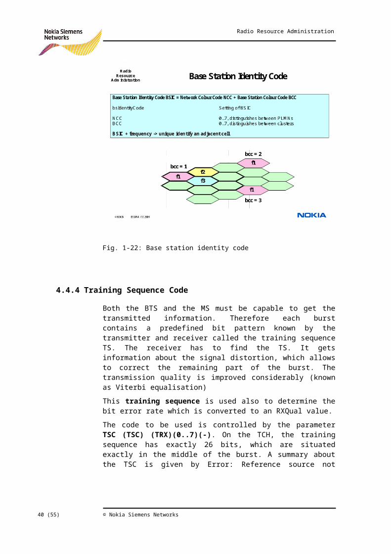
Within a location area, each cell uniquely is identified by the 16 bit long cell identity CI. In dedicated mode the MS identifies cells in its surroundings, however, with the shorter base station identity code BSIC. It can be found in the SCH (Synchronisation Channel) and consists of two parts, each consisting of 3 bits. The network colour code NCC discriminates different PLMNs, while the base station colour code BCC different clusters (see also the following section). Thus the latter enables to distinguish between BTSs transmitting on the same frequency. Frequency and the BSIC give an unique identity for an adjacent cell, which is used e.g. in the measurement reports sent to the BSC. The frequency channel allocation is described by section Error:Reference source not found Error: Reference source not found.
The BCC is set by the parameter BTS Colour Code (BCC)(SEG)(0..7)(-), the NCC is set by the parameter NetworkColourCode (NCC)(SEG)(0..7)(-). The corresponding parameter in the ADJC object (when this cell is defined as neighbour) is updated if the parameters are changed.
© Nokia Siemens Networks 31 (44)

Radio Resource Administration
Fig. 1-22: Base station identity code
4.5.4 Training Sequence Code
Both the BTS and the MS must be capable to get the transmitted information. Therefore each burst contains a predefined bit pattern known by the transmitter and receiver called the training sequence TS. The receiver has to find the TS. It gets information about the signal distortion, which allows to correct the remaining part of the burst. The transmission quality is improved considerably (known as Viterbi equalisation)
This training sequence is used also to determine the bit error rate which is converted to an RXQual value.
The code to be used is controlled by the parameter TSC (TSC) (TRX)(0..7)(-). On the TCH, the training sequence has exactly 26 bits, which are situated exactly in the middle of the burst. A summary about the TSC is given by Error: Reference source not found. The TSC had to be the same as the BCC value. Now it is possible to set a different TSC for non BCCH TRXs.
32 (44) © Nokia Siemens Networks

Radio Resource Administration
Fig. 1-23: Training Sequence Code
4.6 Frequency Administration
4.6.1 Overview
4.6.1.1 Frequency Division Multiple Access
GSM is a FDMA / TDMA system, i.e. physical channels are defined both by frequency and timeslot. Furthermore, GSM is a FDD system, i.e. for uplink and downlink different frequencies are used.
Different frequency ranges are available for GSM, as shown by the following table.
GSM System UL / MHz DL / MHz
800 824-849 869-894
900 (primary) 890-915 935-960
© Nokia Siemens Networks 33 (44)

Radio Resource Administration
900 (extended) 880-915 925-960
1800 1710-1785 1805-1880
1900 1850-1910 1930-1990
Please note, that in Nokia the extended band has a range from 880-890, 925-935 MHz.
Each frequency range is divided into carriers of 200 KHz. These carriers are numbered and are identified by the absolute radio frequency carrier number ARFCN as shown by Error: Reference source not found. Each ARFCN corresponds to a carrier pair (1 for uplink and 1 for downlink).
Fig. 1-24: Frequency division multiple access
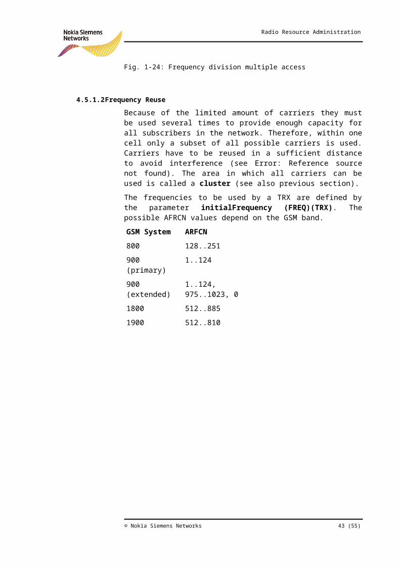
4.6.1.2 Frequency Reuse
Because of the limited amount of carriers they must be used several times to provide enough capacity for all subscribers in the network. Therefore, within one cell only a subset of all possible carriers is used. Carriers have to be reused in a sufficient distance to avoid interference (see Error: Reference source not found). The area in which all carriers can be used is called a cluster (see also previous section).
The frequencies to be used by a TRX are defined by the parameter initialFrequency (FREQ)(TRX). The possible AFRCN values depend on the GSM band.
34 (44) © Nokia Siemens Networks

Radio Resource Administration
GSM System ARFCN
800 128..251
900 (primary) 1..124
900 (extended) 1..124, 975..1023, 0
1800 512..885
1900 512..810
Fig. 1-25: Frequency reuse
4.6.1.3 Frequency Information for MS
The MS must know which carriers are used within the serving (for TCH) and the adjacent cells (for reporting neighbours). In idle mode, it listens to the BCCH, where it gets the BCCH Allocation (BA) list, the BCCH frequencies of neighbours. The MS will only measure these frequencies in order to find a better cell. The BA list to be broadcast can contain BCCH frequencies of those cells that are defined as adjacent cells or ARFCNs from a double BCCH allocation list defined independently in the BSC. This is controlled by the parameter idleStateBCCHAllocation (IDLE)(SEG)(0..255)(0). Up to 255 lists may be defined per BSC. Taking the default setting (i.e. value = 0) the ARFCNs of the defined neighbours is broadcast. Otherwise the parameter identifies one double BCCH allocation list . The ARFCNs of the double BCCH allocation list are set
© Nokia Siemens Networks 35 (44)

Radio Resource Administration
by the parameter bCCHAllocationList ()(BA). This parameter does not have a short name.
Each list can have a maximum of 32 ARFCN values (that is as well the maximum number of GSM neighbours that can be defined for one cell). If one of the features "Common BCCH" or "ISHO support in BSC" is enabled, the maximum is 31. If both features are active, the maximum is 30. The BCCH Allocation Frequency List is selected by the parameter bCCHAllocation-id on BSC level. Its value range is 1…255.
In dedicated mode the MS gets the frequency information about the BCCH carriers of neighbours to be measured on the SACCH. Again the BCCH frequency list is taken from the initialFrequency lists of the adjacent cells or the same double BCCH allocation list as in idle mode may be used. The parameter measurementBCCHAllocation (ACT)(SEG)(ADJ,IDLE) (ADJ) defines that.
Fig. 1-26: Frequency information for MS
4.6.1.4 Principle of Frequency Hopping
Frequency hopping denotes the feature where the frequency is changed from TDMA to TDMA frame. Thereby several frequencies can be used during a connection. This reduces the effects of frequency selective fading and interference. It results in a hopping gain (that means frequency hopping makes ongoing connections more stable, less sensible to air interface specific problems). The hopping gain depends on the number of used frequencies. Usually the hopping gain increases
36 (44) © Nokia Siemens Networks

Radio Resource Administration
with the number of frequencies to hop over. The standard allows the usage of 63 Frequencies for one connection.
There are two techniques to implement frequency hopping: base band and radio frequency hopping (sometimes called synthesized hopping). The kind of frequency hopping is controlled by the parameter btsIsHopping (HOP)(BTS)(BB,RF,N)(-) per BTS. BB corresponds to base band and RF to radio frequency hopping. Setting the parameter to N frequency hopping is not active (see Error: Reference source notfound)
Fig. 1-27: Principles of frequency hopping
4.6.2 Base Band Hopping
With base band hopping the individual TRXs do not change the frequency. Instead the data for one user is moved from one TRX to another. This technique requires distribution of the base band signal streams between the transceivers of one BTS.
There are two hopping sequence numbers required, one for timeslot 0 and one for the other timeslots. Timeslot 0 of the BCCH TRX must not hop. The information sent on the BCCH timeslot has to be on a fixed frequency. On all other TRXs (one TRX gives one frequency) the traffic using timeslot 0 may hop (but the number of frequencies to hop over is
© Nokia Siemens Networks 37 (44)

Radio Resource Administration
reduced by one compared to timeslots 1-7). The hopping sequence for timeslot 0 of non BCCH TRXs is set by the parameter hoppingSequenceNumber (HSN1)(BTS) (0..63)(0). The setting 0 indicates cyclic hopping, all other values indicate pseudorandom hopping. The hopping sequence for all other timeslots is defined by hoppingSequenceNumber (HSN2)(BTS) (0..63)(0). Base band hopping is summarized by Fig. 1-28.
Fig. 1-28: Base band hopping
4.6.3 RF Hopping
4.6.3.1 Standard Technique
In case of RF hopping, the TRXs may change their frequency with each TDMA frame. One TRX will carry the bursts for one user. The TRX carrying the BCCH cannot change its frequency. Therefore with RF hopping all channels on the BCCH TRX do not hop (will work on constant BCCH frequency). So RF hopping offers hopping (all timeslots on non BCCH TRX) and not hopping resources (timeslot 1-7 on BCCH TRX). Depending on the frequency plan and traffic (carried load) these resources have a different quality.
38 (44) © Nokia Siemens Networks

Radio Resource Administration
With RF hopping the number of frequencies used for hopping is not limited by the number of TRXs in the cell. RF hopping allows the use of up to 63 frequencies. Thus RF usually offers a better hopping gain. The frequencies are defined in form of a mobile allocation list, which is set by the parameter mobileAllocationList ()(MA). This parameter does not have a short name. Up to 255 such lists can be defined per BSC. The list which shall be used in one BTS is indicated by the parameter usedMobileAllocation (MAL)(BTS)(0..255)(0). In case of the setting 0 the BTS is detached from any mobile allocation list. The hopping sequence is set in the same way as for base band hopping. For RF hopping, however, only one hopping sequence number is required, which is valid for all the hopping TRXs. The standard RF hopping is summarized by Fig. 1-29.
Fig. 1-29: RF hopping (standard technique)
4.6.3.2 Freeform RF Hopping
Let us consider a 3-sector site, with 4 TRXs for each sector. If we do base band hopping 4 frequencies are required per sector. To avoid frequency collisions between the sectors we need 12 frequencies for the site.
In standard RF hopping we also need (at least) 12 frequencies. In each sector the BCCH TRX does not hop, so there are 3 TRXs with fixed frequencies. The other TRXs are hopping. TRXs in one sector and neighbouring sectors should work at any given time on different
© Nokia Siemens Networks 39 (44)
Radio Resource Administration
frequencies requiring (at least) 9 frequencies. Each sector gets its own MA list containing (at least) 3 frequencies.
With freeform hopping also (at least) 12 frequencies are needed for that side. But now 3 BCCH frequencies (one per sector, BCCH TRX) and at least 9 hopping frequencies (one per TCH TRX, 1 MA list for the site) are needed. All sectors will share the hopping frequencies resulting in an increased hopping gain. Every sector has to use the same hopping sequence number and also the same frame number (i.e. they must be frame synchronized). Then collisions can be avoided, if every sector has a different starting point for the hopping sequence. In our example the first sector must start with frequency 0, the next one with frequency 3, and the last one with frequency 6. Then for every TRX 9 hopping frequencies are available without increasing the total number of frequencies.
The starting point of the hopping sequence can be controlled by the so-called mobile allocation index offset MAIO. This is done by the parameter maioOffset (MO)(BTS)(0..62)(0). In case of the setting 0 the feature is not used. The freeform hopping is summarized by Fig. 1-30.
Fig. 1-30: RF hopping (freeform hopping)
4.6.3.3 Flexible MAIO Management
Often it is necessary to use frequency channels with consecutive ARFCN values. In this case the freeform hopping still is not adequate, as
40 (44) © Nokia Siemens Networks

Radio Resource Administration
its avoid co-channel interference, but no adjacent channel interference. This problem can be solved with a MAIO increasing with constant step size from one TRX to the next one. In our example we start with the first hopping TRX of sector 1 (TRX 2), which gets a MAIO of 0. TRX 3 gets a MAIO = 2, TRX 4 a MAIO = 4 and so on. The last hopping TRX of sector 3 (TRX 12) gets a MAIO = 16. One can see, that this scheme requires twice as much frequencies than the original example (the number of frequencies has to contain at least 2 times the number of frequencies as number of TCH TRXs in that site).
The setting of such a scheme is realized by the additional parameter maioStep (BMS)(BTS)(0..62)(1). In our example it is set to 2. The maioOffset parameter now has to be set to 0, 6 and 12 for sector 1, 2 and 3, respectively. Flexible MAIO management is summarized by Fig.1-31.
Fig. 1-31: RF hopping (flexible MAIO management)
By avoiding both co-channel and adjacent channel interference automatically, flexible MAIO management also makes frequency planning easier. When using the simple freeform hopping, different MA lists with discrete ARFCN values must be defined carefully to overcome both kinds of interference. A complex frequency plan is required, as usually one list cannot be reused for every cell.
Flexible MAIO management allows the use of a MA list with consecutive ARFCN values. Often one and the same list can be used for every cell,
© Nokia Siemens Networks 41 (44)

Radio Resource Administration
i.e. a reuse = 1 is possible (see Fig. 1-32).
Fig. 1-32: RF hopping (tight frequency reuse)
4.6.4 Change of Frequency Plan
If new cells or frequency channels are added to the network, a substantial change of the frequency plan might be required. This must be done without remarkable degradation of the performance for the user, i.e. overnight.
The usual way to change the frequency plan is to lock each TRX individually, change its configuration, and to unlock it again, using Nokia NetAct. For a large network, however, this can take too much time.
The feature "Change of Frequency Plan" allows downloading to the background database a new frequency plan, either from Nokia NetAct or the local MML interface, without changing the current plan. If an error occurs during this process, the download can be repeated without disturbing the performance of the network.
After successful download the new plan is activated quickly, so that the network is disturbed only a short time in comparison to the usual technique. The BSC keeps a backup of the old plan. It can be reactivated quickly on demand.
42 (44) © Nokia Siemens Networks
Radio Resource Administration
The following parameters can be changed by the download: BSIC, TSC, frequencies, frequency hopping settings and also TRX settings for intelligent underlay overlay.
Typical background parameters are:
BTS parameters:
Background Network Colour Code
Background BTS Colour Code
Background BTS Hopping Mode
Background Underlay BTS Hopping Mode
Background Hopping Sequence Number 1
Background Hopping Sequence Number 2
Background Underlay Hopping Sequence Number
Background MA Frequency list
Background Underlay MA Frequency list
Background MAIO Offset
Background Underlay MAIO Offset
Background MAIO Step
Background Underlay MAIO Step
Adjacent Cell parameters:
Background Network Colour Code
Background BTS Colour Code
Background Frequency Number of BCCH
TRX parameters:
Background Frequency
Background Optimum RX Level Uplink
Background TRX Frequency Type
Background Location Area Code of Interfering Cell 1 .. 10
Background Cell Identification of Interfering Cell 1 .. 10
Background Level Adjustment of Interfering Cell 1 .. 10
Background C/I estimation weight parameter for Interfering Cell 1 .. 10
Background C/I estimation type for Interfering Cell 1 .. 10
Background direct access level (IUO) –109…-47 dBm
© Nokia Siemens Networks 43 (44)

Radio Resource Administration
Fig. 1-33: Frequency Plan Changing
44 (44) © Nokia Siemens Networks