01 im2063rev01 - eng - lincoln electric
TRANSCRIPT

IM2063 10/2017 REV01
NA-5S
OPERATOR’S MANUAL
ENGLISH
THE LINCOLN ELECTRIC COMPANY 22801 St. Clair Ave., Cleveland Ohio 44117-1199 USA
www.lincolnelectric.eu
English English I
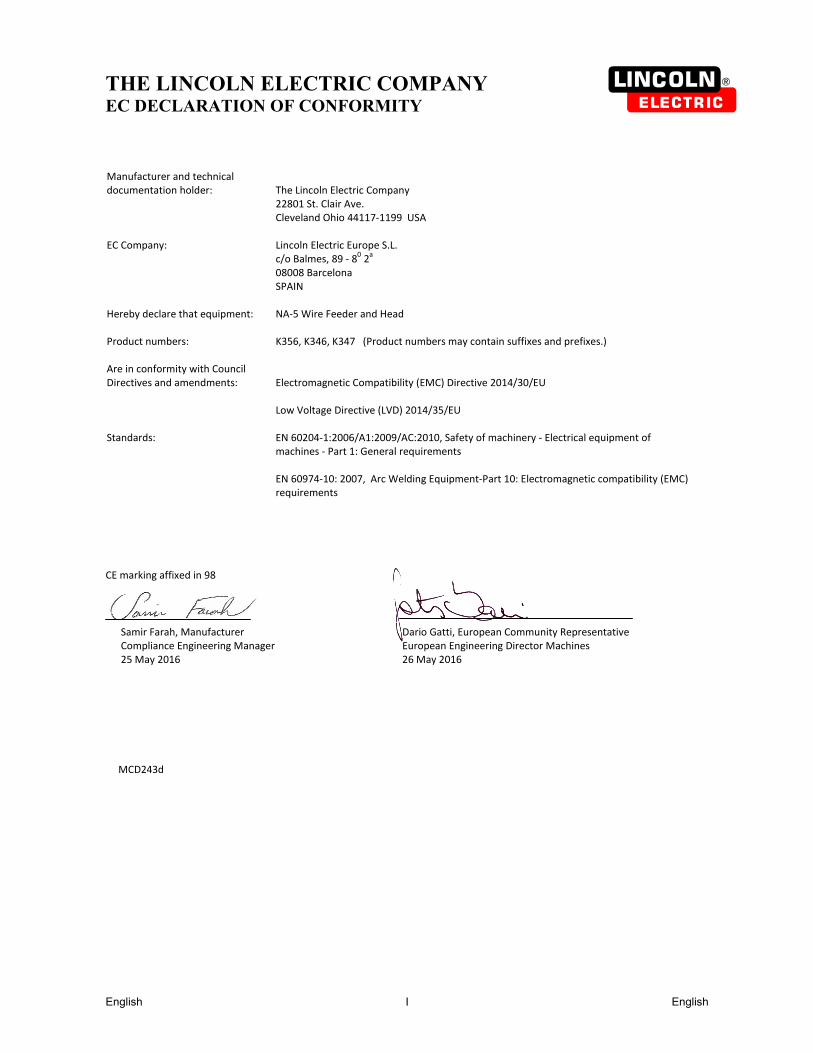
THE LINCOLN ELECTRIC COMPANY
EC DECLARATION OF CONFORMITY Manufacturer and technical documentation holder:
The Lincoln Electric Company 22801 St. Clair Ave. Cleveland Ohio 44117‐1199 USA
EC Company:
Lincoln Electric Europe S.L. c/o Balmes, 89 ‐ 8
0 2
a
08008 Barcelona SPAIN
Hereby declare that equipment: Product numbers:
NA‐5 Wire Feeder and Head K356, K346, K347 (Product numbers may contain suffixes and prefixes.)
Are in conformity with Council Directives and amendments:
Electromagnetic Compatibility (EMC) Directive 2014/30/EU Low Voltage Directive (LVD) 2014/35/EU
Standards: EN 60204‐1:2006/A1:2009/AC:2010, Safety of machinery ‐ Electrical equipment of machines ‐ Part 1: General requirements EN 60974‐10: 2007, Arc Welding Equipment‐Part 10: Electromagnetic compatibility (EMC) requirements
CE marking affixed in 98
Samir Farah, Manufacturer Dario Gatti, European Community Representative Compliance Engineering Manager European Engineering Director Machines 25 May 2016
26 May 2016
MCD243d

English English II
12/05
THANKS! For having chosen the QUALITY of the Lincoln Electric products. Please Examine Package and Equipment for Damage. Claims for material damaged in shipment must be notified
immediately to the dealer. For future reference record in the table below your equipment identification information. Model Name, Code &
Serial Number can be found on the machine rating plate.
Model Name:
………………...…………………………….…………………………………………………………………………………………..Code & Serial number:
………………….……………………………………………….. …………………………………………………….……………..
Date & Where Purchased:
…………………………………………………………………... ……………………….…………………………………………..
ENGLISH INDEX Electromagnetic Compatibility (EMC) ....................................................................... Errore. Il segnalibro non è definito. Safety .................................................................................................................................................................................. 4 Mechanical Installation ........................................................................................................................................................ 6 Electrical Installation ......................................................................................................................................................... 21 Operatoring Instruction ...................................................................................................................................................... 32 Maintenance ...................................................................................................................................................................... 45 WEEE ................................................................................................................................................................................ 47 Spare Parts ............................................................................................................... Errore. Il segnalibro non è definito.

Electromagnetic Compatibility (EMC) 01/11
This machine has been designed in accordance with all relevant directives and standards. However, it may still generate electromagnetic disturbances that can affect other systems like telecommunications (telephone, radio, and television) or other safety systems. These disturbances can cause safety problems in the affected systems. Read and understand this section to eliminate or reduce the amount of electromagnetic disturbance generated by this machine.
This machine has been designed to operate in an industrial area. To operate in a domestic area it is necessary to observe particular precautions to eliminate possible electromagnetic disturbances. The operator must install and operate this equipment as described in this manual. If any electromagnetic disturbances are detected the operator must put in place corrective actions to eliminate these disturbances with, if necessary, assistance from
Lincoln Electric. Before installing the machine, the operator must check the work area for any devices that may malfunction because of electromagnetic disturbances. Consider the following. Input and output cables, control cables, and telephone cables that are in or adjacent to the work area and the machine. Radio and/or television transmitters and receivers. Computers or computer controlled equipment. Safety and control equipment for industrial processes. Equipment for calibration and measurement. Personal medical devices like pacemakers and hearing aids. Check the electromagnetic immunity for equipment operating in or near the work area. The operator must be sure that all
equipment in the area is compatible. This may require additional protection measures. The dimensions of the work area to consider will depend on the construction of the area and other activities that are taking
place. Consider the following guidelines to reduce electromagnetic emissions from the machine. Connect the machine to the input supply according to this manual. If disturbances occur if may be necessary to take
additional precautions such as filtering the input supply. The output cables should be kept as short as possible and should be positioned together. If possible connect the work
piece to ground in order to reduce the electromagnetic emissions. The operator must check that connecting the work piece to ground does not cause problems or unsafe operating conditions for personnel and equipment.
Shielding of cables in the work area can reduce electromagnetic emissions. This may be necessary for special applications.
WARNING EMC classification of this product is class A in accordance with electromagnetic compatibility standard EN 60974-10 and therefore the product is designed to be used in an industrial environment only.
WARNING The Class A equipment is not intended for use in residential locations where the electrical power is provided by the public low-voltage supply system. There can be potential difficulties in ensuring electromagnetic compatibility in those locations, due to conducted as well as radio-frequency disturbances.
English English 4
Safety 11/04
WARNING This equipment must be used by qualified personnel. Be sure that all installation, operation, maintenance and repair procedures are performed only by qualified person. Read and understand this manual before operating this equipment. Failure to follow the instructions in this manual could cause serious personal injury, loss of life, or damage to this equipment. Read and understand the following explanations of the warning symbols. Lincoln Electric is not responsible for damages caused by improper installation, improper care or abnormal operation.
WARNING: This symbol indicates that instructions must be followed to avoid serious personal injury, loss of life, or damage to this equipment. Protect yourself and others from possible serious injury or death.
READ AND UNDERSTAND INSTRUCTIONS: Read and understand this manual before operating this equipment. Arc welding can be hazardous. Failure to follow the instructions in this manual could cause serious personal injury, loss of life, or damage to this equipment.
ELECTRIC SHOCK CAN KILL: Welding equipment generates high voltages. Do not touch the electrode, work clamp, or connected work pieces when this equipment is on. Insulate yourself from the electrode, work clamp, and connected work pieces.
ELECTRICALLY POWERED EQUIPMENT: Turn off input power using the disconnect switch at the fuse box before working on this equipment. Ground this equipment in accordance with local electrical regulations.
ELECTRICALLY POWERED EQUIPMENT: Regularly inspect the input, electrode, and work clamp cables. If any insulation damage exists replace the cable immediately. Do not place the electrode holder directly on the welding table or any other surface in contact with the work clamp to avoid the risk of accidental arc ignition.
ELECTRIC AND MAGNETIC FIELDS MAY BE DANGEROUS: Electric current flowing through any conductor creates electric and magnetic fields (EMF). EMF fields may interfere with some pacemakers, and welders having a pacemaker shall consult their physician before operating this equipment.
CE COMPLIANCE: This equipment complies with the European Community Directives.
FUMES AND GASES CAN BE DANGEROUS: Welding may produce fumes and gases hazardous to health. Avoid breathing these fumes and gases. To avoid these dangers the operator must use enough ventilation or exhaust to keep fumes and gases away from the breathing zone.
ARC RAYS CAN BURN: Use a shield with the proper filter and cover plates to protect your eyes from sparks and the rays of the arc when welding or observing. Use suitable clothing made from durable flame-resistant material to protect you skin and that of your helpers. Protect other nearby personnel with suitable, non-flammable screening and warn them not to watch the arc nor expose themselves to the arc.
WELDING SPARKS CAN CAUSE FIRE OR EXPLOSION: Remove fire hazards from the welding area and have a fire extinguisher readily available. Welding sparks and hot materials from the welding process can easily go through small cracks and openings to adjacent areas. Do not weld on any tanks, drums, containers, or material until the proper steps have been taken to insure that no flammable or toxic vapors will be present. Never operate this equipment when flammable gases, vapors or liquid combustibles are present.
WELDED MATERIALS CAN BURN: Welding generates a large amount of heat. Hot surfaces and materials in work area can cause serious burns. Use gloves and pliers when touching or moving materials in the work area.
SAFETY MARK: This equipment is suitable for supplying power for welding operations carried out in an environment with increased hazard of electric shock.
English English 5
CYLINDER MAY EXPLODE IF DAMAGED: Use only compressed gas cylinders containing the correct shielding gas for the process used and properly operating regulators designed for the gas and pressure used. Always keep cylinders in an upright position securely chained to a fixed support. Do not move or transport gas cylinders with the protection cap removed. Do not allow the electrode, electrode holder, work clamp or any other electrically live part to touch a gas cylinder. Gas cylinders must be located away from areas where they may be subjected to physical damage or the welding process including sparks and heat sources.
NOISE APPEARES DURING WELDING CAN BE HARMFUL: Welding arc can cause noise with high level of 85dB for 8-hour week day. Welders operating welding machines are obligated to wear the proper ear protectors /appendix No. 2 for the Decree of the Secretary of Labor and Social Policy from 17.06 1998 – Dz.U. No. 79 pos. 513/. According to the Decree the Secretary of Health and Social Welfare from 09.07.1996 /Dz.U. No. 68 pos. 194/, employers are obligated to carry examinations and measurements of health harmful factors. MOVING PARTS ARE DANGEROUS: There are moving mechanical parts in this machine, which can cause serious injury. Keep your hands, body and clothing away from those parts during machine starting, operating and servicing.
EQUIPMENT WEIGHT OVER 30kg: Move this equipment with care and with the help of another person. Lifting may be dangerous for your physical health.
English English 6
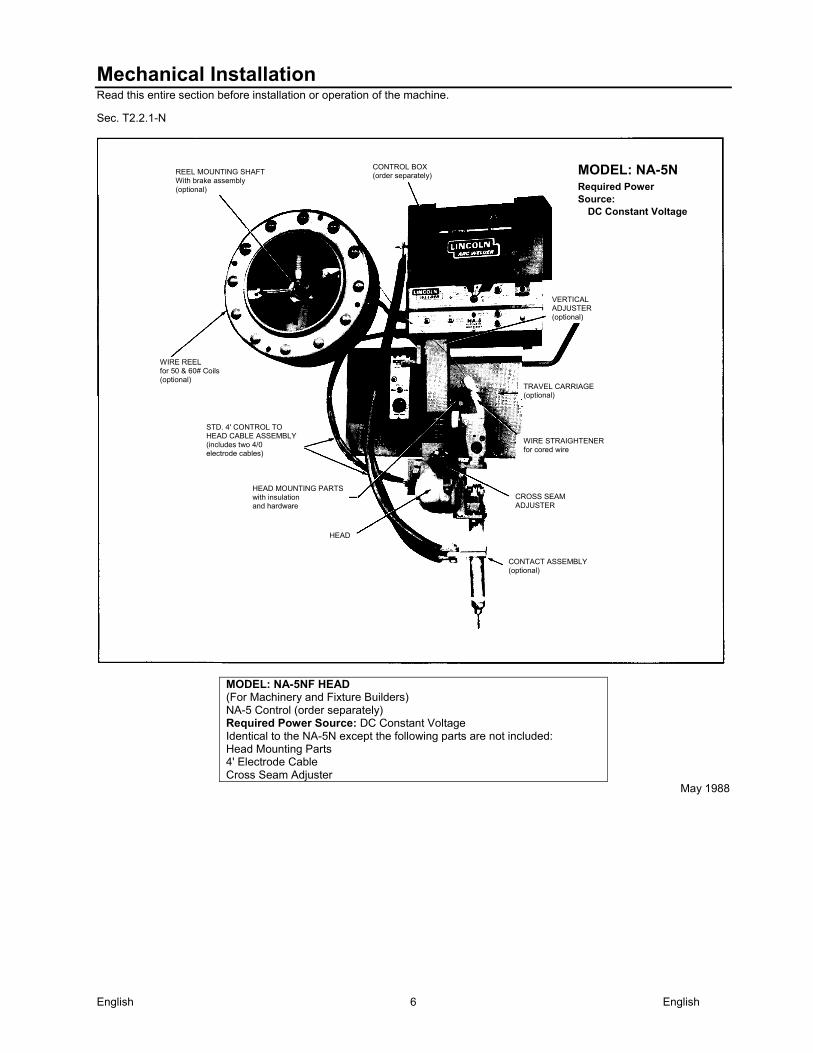
Mechanical Installation Read this entire section before installation or operation of the machine.
Sec. T2.2.1-N
MODEL: NA-5NF HEAD (For Machinery and Fixture Builders) NA-5 Control (order separately) Required Power Source: DC Constant Voltage Identical to the NA-5N except the following parts are not included: Head Mounting Parts 4' Electrode Cable Cross Seam Adjuster
May 1988
REEL MOUNTING SHAFT With brake assembly (optional)
WIRE REEL for 50 & 60# Coils (optional)
CONTROL BOX (order separately)
VERTICAL ADJUSTER (optional)
TRAVEL CARRIAGE (optional)
WIRE STRAIGHTENER for cored wire
CROSS SEAM ADJUSTER
CONTACT ASSEMBLY (optional)
HEAD
HEAD MOUNTING PARTS with insulation and hardware
STD. 4' CONTROL TO HEAD CABLE ASSEMBLY (includes two 4/0 electrode cables)
MODEL: NA-5NRequired Power Source:
DC Constant Voltage
English English 7
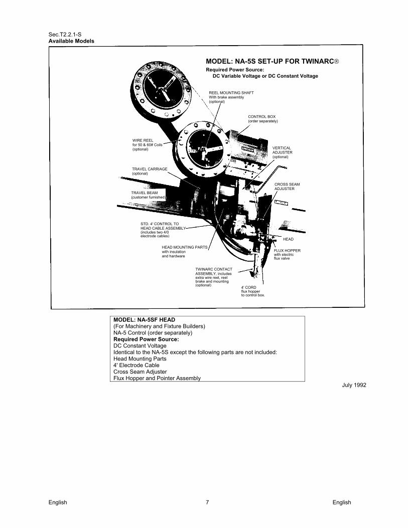
Sec.T2.2.1-S Available Models
MODEL: NA-5SF HEAD (For Machinery and Fixture Builders) NA-5 Control (order separately) Required Power Source: DC Constant Voltage Identical to the NA-5S except the following parts are not included: Head Mounting Parts 4' Electrode Cable Cross Seam Adjuster Flux Hopper and Pointer Assembly
July 1992
MODEL: NA-5S SET-UP FOR TWINARCRequired Power Source:
DC Variable Voltage or DC Constant Voltage
REEL MOUNTING SHAFT With brake assembly (optional)
CONTROL BOX (order separately)
CROSS SEAM ADJUSTER
VERTICAL ADJUSTER (optional)
HEAD
WIRE REEL for 50 & 60# Coils (optional)
TRAVEL CARRIAGE (optional)
STD. 4' CONTROL TO HEAD CABLE ASSEMBLY (includes two 4/0 electrode cables)
HEAD MOUNTING PARTS with insulation and hardware
TWINARC CONTACT ASSEMBLY, includes extra wire reel, reel brake and mounting (optional)
4' CORD flux hopper to control box.
FLUX HOPPER with electric flux valve
TRAVEL BEAM (customer furnished)
English English 8
As Shipped
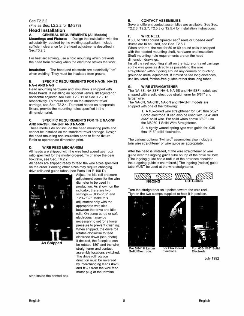
Sec.T2.2.2 (File as Sec. L2.2.2 for IM-278) Head Installation A. GENERAL REQUIREMENTS (All Models) Mountings and Fixtures — Design the installation with the adjustability required by the welding application. Include sufficient clearance for the head adjustments described in Sec.T3.2.3. For best arc striking, use a rigid mounting which prevents the head from moving when the electrode strikes the work. Insulation — The head and electrode are electrically “hot” when welding. They must be insulated from ground. B. SPECIFIC REQUIREMENTS FOR NA-3N, NA-3S, NA-4 AND NA-5 Head mounting hardware and insulation is shipped with these heads. If installing an optional vertical lift adjuster or horizontal adjuster, see Sec. T2.2.11 or Sec. T2.2.12 respectively. To mount heads on the standard travel carriage, see Sec. T2.2.4. To mount heads on a separate fixture, provide the mounting holes specified in the dimension print. C. SPECIFIC REQUIREMENTS FOR THE NA-3NF AND NA-3SF, NA-5NF AND NA-5SF These models do not include the head mounting parts and cannot be installed on the standard travel carriage. Design the head mounting and insulation parts to fit the fixture. Refer to appropriate dimension print. D. WlRE FEED MECHANISM All heads are shipped with the wire feed speed gear box ratio specified for the model ordered. To change the gear box ratio, see Sec. T6.2.2. All heads are shipped ready to feed the wire sizes specified on the order. Feeding other sizes may require changing drive rolls and guide tubes (see Parts List P-100-D).
Adjust the idle roll pressure adjustment screw for the wire diameter to be used in production. As shown on the indicator, there are two settings — .035-3/32" and .120-7/32". Make this adjustment only with the appropriate wire size between the drive and idle rolls. On some cored or soft electrodes it may be necessary to set for a lower pressure to prevent crushing. When shipped, the drive roll rotates clockwise to feed electrode down (see photo). If desired, the faceplate can be rotated 180° and the wire straightener and contact assembly locations switched. The drive roll rotation direction must be reversed by interchanging leads #626 and #627 from the wire feed motor plug at the terminal
strip inside the control box.
E. CONTACT ASSEMBLIES Several different contact assemblies are available. See Sec. T2.2.6, T2.2.7, T2.5.3 or T2.5.4 for installation instructions. F. WlRE REEL If 300 to 1000 pound Speed-Feed® reels or Speed-Feed®
drums are to be used, see Sec. T2.5.7. When ordered, the reel for 50 or 60 pound coils is shipped with the needed mounting shaft, hardware and insulation. Shaft mounting hole requirements are on the head dimension drawings. Install the reel mounting shaft on the fixture or travel carriage so the wire goes as directly as possible to the wire straightener without going around any corners or touching grounded metal equipment. If it must be fed long distances, use insulated, friction-free guides rather than long tubes. G. WlRE STRAIGHTENER The NA-3S, NA-3SF, NA-4, NA-5S and NA-5SF models are shipped with a solid electrode straightener for 5/64'' and larger wire. The NA-3N, NA-3NF, NA-5N and NA-5NF models are shipped with one of the following:
1. A flux-cored wire straightener for .045 thru 5/32'' Cored electrode. It can also be used with 5/64" and 3/32" solid wire. For solid wires above 3/32", use the M8269-1 Solid Wire Straightener.
2. A tightly wound spring type wire guide for .035 thru 1/16" solid electrodes.
The various optional Twinarc® assemblies also include a twin wire straightener or wire guide as appropriate. After the head is installed, fit the wire straightener or wire guide over the ingoing guide tube on top of the drive roll box. (The ingoing guide has a radius at the entrance shoulder — the outgoing guide is chamfered.) The ingoing (radius) guide tube MUST be used at the wire straightener.
Turn the straightener so it points toward the wire reel. Tighten the two clamps supplied to hold it in position.
July 1992
OUTGOINGINGOING
For 5/64" & LargerSolid Electrode.
For Flux Cored Electrode.
For .035-1/16" SolidElectrode.
English English 9
Sec. T2.2.3
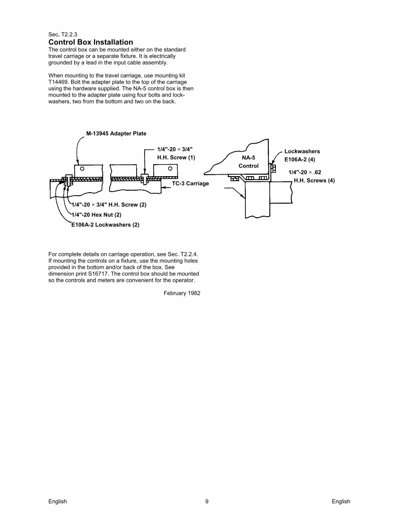
Control Box Installation The control box can be mounted either on the standard travel carriage or a separate fixture. It is electrically grounded by a lead in the input cable assembly. When mounting to the travel carriage, use mounting kit T14469. Bolt the adapter plate to the top of the carriage using the hardware supplied. The NA-5 control box is then mounted to the adapter plate using four bolts and lock-washers, two from the bottom and two on the back.
For complete details on carriage operation, see Sec. T2.2.4. If mounting the controls on a fixture, use the mounting holes provided in the bottom and/or back of the box. See dimension print S16717. The control box should be mounted so the controls and meters are convenient for the operator.
February 1982
M-13945 Adapter Plate
1/4"-20 × 3/4"
H.H. Screw (1) NA-5
Control
Lockwashers
E106A-2 (4)
1/4"-20 × .62
H.H. Screws (4) TC-3 Carriage
1/4"-20 × 3/4" H.H. Screw (2)
1/4"-20 Hex Nut (2)
E106A-2 Lockwashers (2)
English English 10
Sec. T2.2.4-C (File as Sec. L2.2.4-C for IM-278)
K325 Travel Carriage Installation (Codes Above 8000) The carriage is available in two versions: a Standard Carriage for normal loads and a High Capacity (HC) Carriage for heavy loads. The units are convertible from standard to high capacity or from high capacity to standard by changing bearings and a few spacers. The maximum equipment to be used with each type of carriage is shown in the following tables. K325 STANDARD CARRIAGE (Carriage bearing width .472)
Single Wire Operation Twin Wire Operation 1. Single head and
control 2. Single wire reel 3. Vertical adjuster 4. Horizontal adjuster 5. Flux hopper 6. 75 lbs. of auxiliary
equipment centrally located over carriage
1. Single head and control
2. Two wire reels 3. Vertical adjuster 4. Horizontal adjuster 5. Flux hopper 6. No auxiliary
equipment
K325HC HIGH CAPACITY CARRIAGE (Carriage bearing width .866)
Multiple Arc Operation Tandem Twinarc
1. Two heads and controls
2. Two wire reels
3. Vertical adjuster
4. Horizontal adjuster
5. Flux hopper 6. 150 lbs. of
auxiliary equipment centrally located over carriage
1. Three heads and controls
2. Three wire reels
3. Vertical adjuster
4. Horizontal adjuster
5. Flux hopper
6. No auxiliary equipment
1. Two heads and controls
2. Four wire reels centrally located over carriage
3. Vertical adjuster
4. Horizontal adjuster
5. Flux hopper
6. No auxiliary equipment.
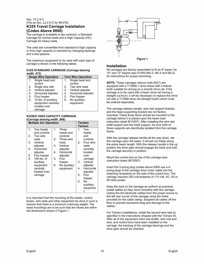
It is important that the mounting of the heads, control boxes, wire reels and other equipment be done in such a manner that there is a minimum overhung weight. The head mountings are to be such that the heads are within the dimensions shown in Figure 1.
Figure 1
Installation All carriages are factory assembled to fit an 8" beam; for 10'' and 12" beams see G1458 (NA-3, NA-4 and NA-5) for instructions for proper shimming. NOTE: These carriages (above code 8427) are equipped with a T13586-1 drive wheel with a helical tooth suitable for driving on a smooth drive rail. If the carriage is to be used with a beam drive rail having a straight cut knurl, it will be necessary to replace the drive roll with a T13586 drive roll (straight tooth) which must be ordered separately. The carriage release handle, wire reel support bracket, and the head supporting bracket are not factory mounted. These three items should be mounted to the carriage before it is placed upon the beam (see instruction sheet M13297). After installing the wire reel shaft support and the head support, be sure both of these supports are electrically isolated from the carriage frame. With the carriage release handle all the way down, set the carriage upon the beam. It should run freely along the entire beam length. With the release handle in the up position the drive gear should engage the track and hold the carriage securely in position. Mount the control box on top of the camage (see instruction sheet (M13297). Insert the 3-prong plug (codes above 8300 use a 4- prong plug) of the carriage drive motor cable into the matching receptacle on the side of the control box. The carriage requires 250 volt-amperes of 115 volt, AC, 50 or 60 hertz power. Keep the load on the carriage as uniform as practical. Install cables so they move smoothly with the carriage. Clamp the 4/0 electrode cables from the power source to the left rear corner of the carriage using the holes provided for the cable clamp. Suspend all cables off the floor to prevent excessive drag and damage to the cables. For Twinarc installations, install the second wire reel as specified in the instructions shipped with the Twinarc kit. After all of the equipment (wire reel shafts, wire reel and wire, and control box) have been installed on the carriage, the tracking of the carriage bearings and the drive gear should be checked.
19"
English English 11
Sec. T2.2.4-C (Continued) The carriage drive unit is properly shimmed at the factory so that the face of the driving gear is flat against a .88 thick beam flange when the release handle is in the up position. If the flange is other than .88 thick the shims under the gear box mounting brackets will have to be changed per Figure 2.
Carriage Bearing Tracking The bearing tracking can be checked by placing a strip of white paper along the area over which each set of bearings ride. Disengage the release handle and move the carriage over these paper strips. If the carriage has been properly installed, the trace on each paper should show a uniform trace left by the bearing face.
February 1982
Sec. T2.2.4-C (Continued) (File as Sec. L2.2.4-C for IM-278) The out-of-squareness between the carriage and the beam can be corrected by shimming the lower bearing assembly bar:
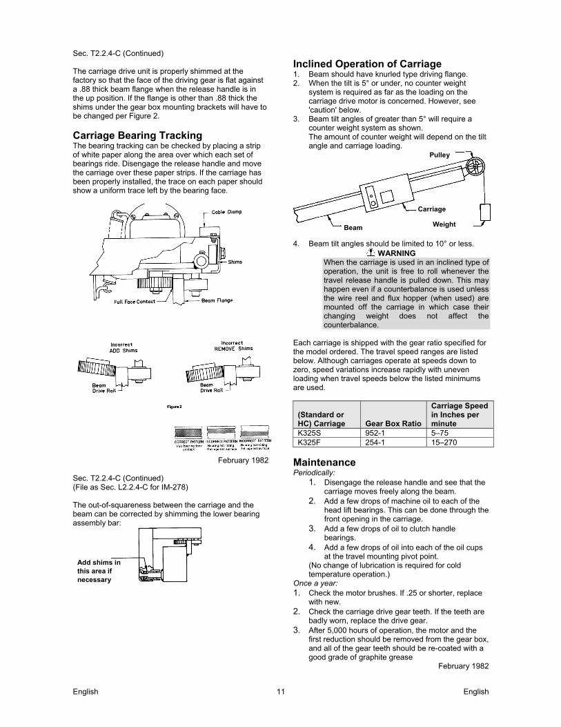
Inclined Operation of Carriage 1. Beam should have knurled type driving flange. 2. When the tilt is 5° or under, no counter weight
system is required as far as the loading on the carriage drive motor is concerned. However, see 'caution' below.
3. Beam tilt angles of greater than 5° will require a counter weight system as shown. The amount of counter weight will depend on the tilt angle and carriage loading.
4. Beam tilt angles should be limited to 10° or less.
WARNING When the carriage is used in an inclined type of operation, the unit is free to roll whenever the travel release handle is pulled down. This may happen even if a counterbalance is used unless the wire reel and flux hopper (when used) are mounted off the carriage in which case their changing weight does not affect the counterbalance.
Each carriage is shipped with the gear ratio specified for the model ordered. The travel speed ranges are listed below. Although carriages operate at speeds down to zero, speed variations increase rapidly with uneven loading when travel speeds below the listed minimums are used.
(Standard or HC) Carriage Gear Box Ratio
Carriage Speed in Inches per minute
K325S 952-1 5–75 K325F 254-1 15–270
Maintenance Periodically:
1. Disengage the release handle and see that the carriage moves freely along the beam.
2. Add a few drops of machine oil to each of the head lift bearings. This can be done through the front opening in the carriage.
3. Add a few drops of oil to clutch handle bearings.
4. Add a few drops of oil into each of the oil cups at the travel mounting pivot point.
(No change of lubrication is required for cold temperature operation.)
Once a year: 1. Check the motor brushes. If .25 or shorter, replace
with new. 2. Check the carriage drive gear teeth. If the teeth are
badly worn, replace the drive gear. 3. After 5,000 hours of operation, the motor and the
first reduction should be removed from the gear box, and all of the gear teeth should be re-coated with a good grade of graphite grease
February 1982
Add shims in this area if necessary
Pulley
Beam
Carriage
Weight
English English 12
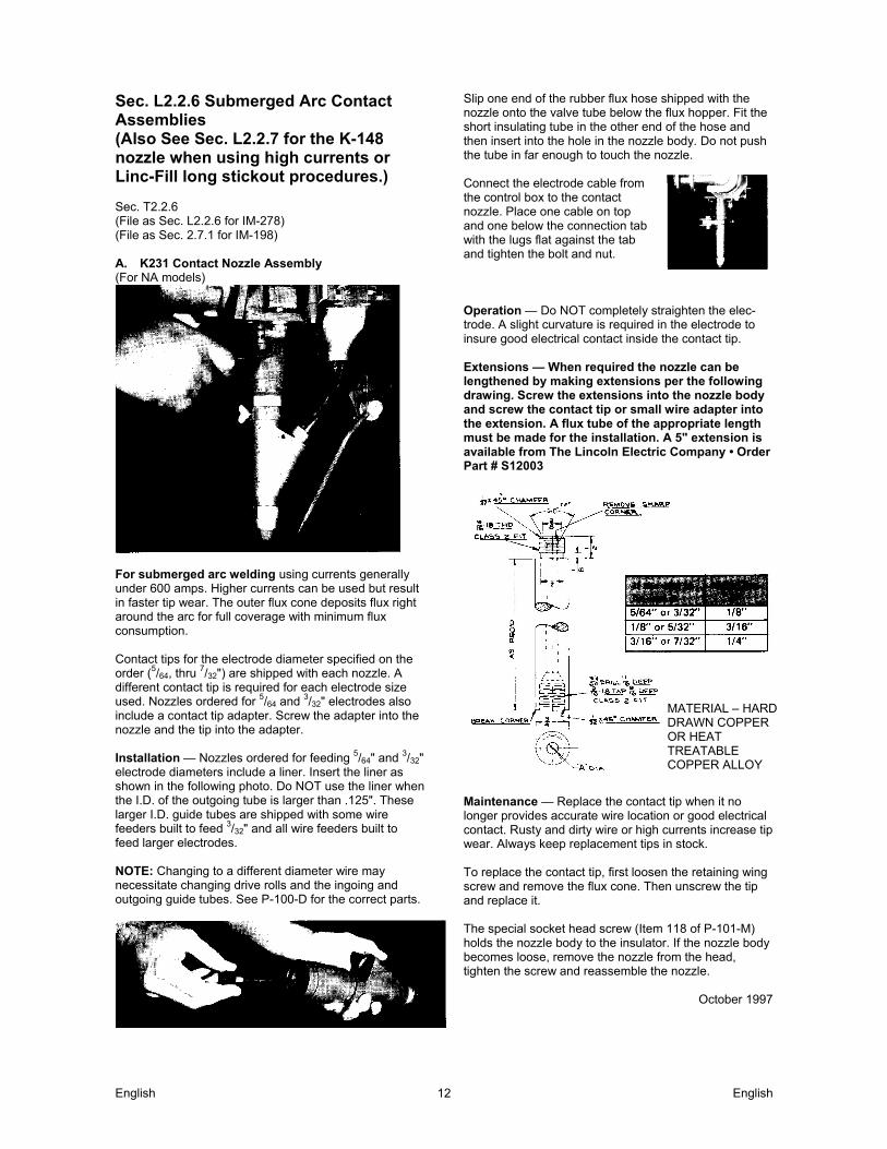
Sec. L2.2.6 Submerged Arc Contact Assemblies (Also See Sec. L2.2.7 for the K-148 nozzle when using high currents or Linc-Fill long stickout procedures.) Sec. T2.2.6 (File as Sec. L2.2.6 for IM-278) (File as Sec. 2.7.1 for IM-198) A. K231 Contact Nozzle Assembly (For NA models)
For submerged arc welding using currents generally under 600 amps. Higher currents can be used but result in faster tip wear. The outer flux cone deposits flux right around the arc for full coverage with minimum flux consumption. Contact tips for the electrode diameter specified on the order (5/64, thru 7/32") are shipped with each nozzle. A different contact tip is required for each electrode size used. Nozzles ordered for 5/64 and 3/32" electrodes also include a contact tip adapter. Screw the adapter into the nozzle and the tip into the adapter. Installation — Nozzles ordered for feeding 5/64" and 3/32" electrode diameters include a liner. Insert the liner as shown in the following photo. Do NOT use the liner when the I.D. of the outgoing tube is larger than .125". These larger I.D. guide tubes are shipped with some wire feeders built to feed 3/32" and all wire feeders built to feed larger electrodes. NOTE: Changing to a different diameter wire may necessitate changing drive rolls and the ingoing and outgoing guide tubes. See P-100-D for the correct parts.
Slip one end of the rubber flux hose shipped with the nozzle onto the valve tube below the flux hopper. Fit the short insulating tube in the other end of the hose and then insert into the hole in the nozzle body. Do not push the tube in far enough to touch the nozzle. Connect the electrode cable from the control box to the contact nozzle. Place one cable on top and one below the connection tab with the lugs flat against the tab and tighten the bolt and nut. Operation — Do NOT completely straighten the elec- trode. A slight curvature is required in the electrode to insure good electrical contact inside the contact tip. Extensions — When required the nozzle can be lengthened by making extensions per the following drawing. Screw the extensions into the nozzle body and screw the contact tip or small wire adapter into the extension. A flux tube of the appropriate length must be made for the installation. A 5" extension is available from The Lincoln Electric Company • Order Part # S12003
Maintenance — Replace the contact tip when it no longer provides accurate wire location or good electrical contact. Rusty and dirty wire or high currents increase tip wear. Always keep replacement tips in stock. To replace the contact tip, first loosen the retaining wing screw and remove the flux cone. Then unscrew the tip and replace it. The special socket head screw (Item 118 of P-101-M) holds the nozzle body to the insulator. If the nozzle body becomes loose, remove the nozzle from the head, tighten the screw and reassemble the nozzle.
October 1997
MATERIAL – HARD DRAWN COPPER OR HEAT TREATABLE COPPER ALLOY
English English 13
B. K226 Contact Jaw Assembly (For Models NA-3, NA-4 and NA-5)
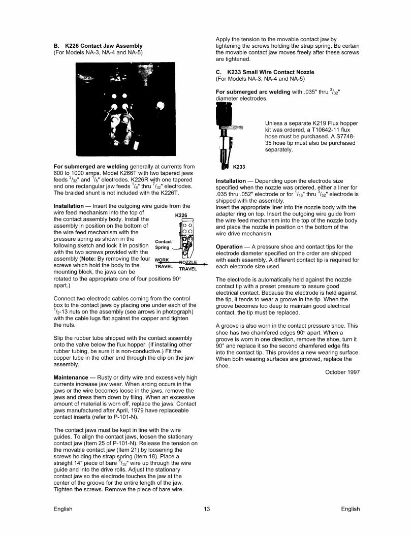
For submerged are welding generally at currents from 600 to 1000 amps. Model K266T with two tapered jaws feeds 3/32" and 1/8" electrodes. K226R with one tapered and one rectangular jaw feeds 1/8" thru 7/32" electrodes. The braided shunt is not included with the K226T. lnstallation — Insert the outgoing wire guide from the wire feed mechanism into the top of the contact assembly body. Install the assembly in position on the bottom of the wire feed mechanism with the pressure spring as shown in the following sketch and lock it in position with the two screws provided with the assembly (Note: By removing the four screws which hold the body to the mounting block, the jaws can be rotated to the appropriate one of four positions 90 apart.) Connect two electrode cables coming from the control box to the contact jaws by placing one under each of the 1/2-13 nuts on the assembly (see arrows in photograph) with the cable lugs flat against the copper and tighten the nuts. Slip the rubber tube shipped with the contact assembly onto the valve below the flux hopper. (If installing other rubber tubing, be sure it is non-conductive.) Fit the copper tube in the other end through the clip on the jaw assembly. Maintenance — Rusty or dirty wire and excessively high currents increase jaw wear. When arcing occurs in the jaws or the wire becomes loose in the jaws, remove the jaws and dress them down by filing. When an excessive amount of material is worn off, replace the jaws. Contact jaws manufactured after April, 1979 have replaceable contact inserts (refer to P-101-N). The contact jaws must be kept in line with the wire guides. To align the contact jaws, loosen the stationary contact jaw (Item 25 of P-101-N). Release the tension on the movable contact jaw (ltem 21) by loosening the screws holding the strap spring (Item 18). Place a straight 14" piece of bare 5/32" wire up through the wire guide and into the drive rolls. Adjust the stationary contact jaw so the electrode touches the jaw at the center of the groove for the entire length of the jaw. Tighten the screws. Remove the piece of bare wire.
Apply the tension to the movable contact jaw by tightening the screws holding the strap spring. Be certain the movable contact jaw moves freely after these screws are tightened. C. K233 Small Wire Contact Nozzle (For Models NA-3, NA-4 and NA-5) For submerged arc welding with .035" thru 3/32" diameter electrodes.
Unless a separate K219 Flux hopper kit was ordered, a T10642-11 flux hose must be purchased. A S7748-35 hose tip must also be purchased separately.
lnstallation — Depending upon the electrode size specified when the nozzle was ordered, either a liner for .035 thru .052" electrode or for 1/16" thru 3/32" electrode is shipped with the assembly. lnsert the appropriate liner into the nozzle body with the adapter ring on top. Insert the outgoing wire guide from the wire feed mechanism into the top of the nozzle body and place the nozzle in position on the bottom of the wire drive mechanism. Operation — A pressure shoe and contact tips for the electrode diameter specified on the order are shipped with each assembly. A different contact tip is required for each electrode size used. The electrode is automatically held against the nozzle contact tip with a preset pressure to assure good electrical contact. Because the electrode is held against the tip, it tends to wear a groove in the tip. When the groove becomes too deep to maintain good electrical contact, the tip must be replaced. A groove is also worn in the contact pressure shoe. This shoe has two chamfered edges 90 apart. When a groove is worn in one direction, remove the shoe, turn it 90° and replace it so the second chamfered edge fits into the contact tip. This provides a new wearing surface. When both wearing surfaces are grooved, replace the shoe.
October 1997
K226
Contact Spring
NOZZLE
TRAVELTRAVEL
WORK
K233
English English 14
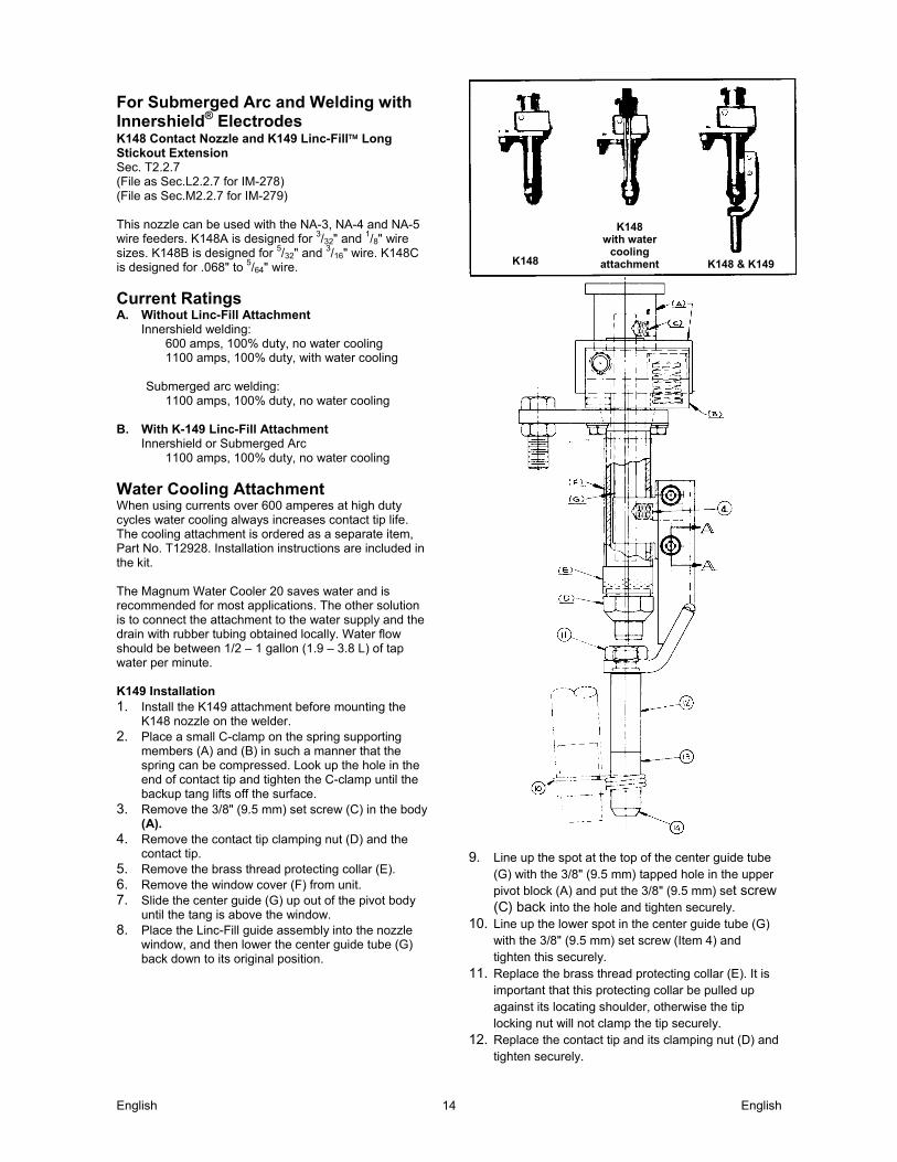
For Submerged Arc and Welding with Innershield® Electrodes K148 Contact Nozzle and K149 Linc-Fill Long Stickout Extension Sec. T2.2.7 (File as Sec.L2.2.7 for IM-278) (File as Sec.M2.2.7 for IM-279) This nozzle can be used with the NA-3, NA-4 and NA-5 wire feeders. K148A is designed for 3/32" and 1/8" wire sizes. K148B is designed for 5/32" and 3/16" wire. K148C is designed for .068" to 5/64" wire.
Current Ratings A. Without Linc-Fill Attachment
Innershield welding: 600 amps, 100% duty, no water cooling 1100 amps, 100% duty, with water cooling
Submerged arc welding:
1100 amps, 100% duty, no water cooling B. With K-149 Linc-Fill Attachment
Innershield or Submerged Arc 1100 amps, 100% duty, no water cooling
Water Cooling Attachment When using currents over 600 amperes at high duty cycles water cooling always increases contact tip life. The cooling attachment is ordered as a separate item, Part No. T12928. Installation instructions are included in the kit. The Magnum Water Cooler 20 saves water and is recommended for most applications. The other solution is to connect the attachment to the water supply and the drain with rubber tubing obtained locally. Water flow should be between 1/2 – 1 gallon (1.9 – 3.8 L) of tap water per minute. K149 Installation 1. Install the K149 attachment before mounting the
K148 nozzle on the welder. 2. Place a small C-clamp on the spring supporting
members (A) and (B) in such a manner that the spring can be compressed. Look up the hole in the end of contact tip and tighten the C-clamp until the backup tang lifts off the surface.
3. Remove the 3/8" (9.5 mm) set screw (C) in the body (A).
4. Remove the contact tip clamping nut (D) and the contact tip.
5. Remove the brass thread protecting collar (E). 6. Remove the window cover (F) from unit. 7. Slide the center guide (G) up out of the pivot body
until the tang is above the window. 8. Place the Linc-Fill guide assembly into the nozzle
window, and then lower the center guide tube (G) back down to its original position.
9. Line up the spot at the top of the center guide tube
(G) with the 3/8" (9.5 mm) tapped hole in the upper pivot block (A) and put the 3/8" (9.5 mm) set screw (C) back into the hole and tighten securely.
10. Line up the lower spot in the center guide tube (G) with the 3/8" (9.5 mm) set screw (Item 4) and tighten this securely.
11. Replace the brass thread protecting collar (E). It is important that this protecting collar be pulled up against its locating shoulder, otherwise the tip locking nut will not clamp the tip securely.
12. Replace the contact tip and its clamping nut (D) and tighten securely.
K148
K148 with water
cooling attachment K148 & K149

English English 15
13. Assemble the proper combination of extension guides (Items 12, 13 and 14) with locking nut (Item 11) for the welding procedure to be used.
14. If Submerged Arc welding is being used, screw the flux hose clamp (Item 10) onto the extension housing.
K148 Nozzle Installation To install the nozzle on the head, insert the outgoing wire guide from the head into the nozzle assembly. Place the combined assembly in position on the bottom of the wire feed roll box. Clamp it in place using the two clamps supplied with the head. Before pulling the clamps up tight the nozzle must be positioned relative to the travel direction as shown in Figure 1. This position is set so accidental contact between the work and the nozzle will not compress the contact pressure spring. If positioned otherwise, such accidental contact may cause arcing inside the contact tip. After the nozzle is positioned in the proper relationship with the travel direction, the connector tab for the electrode cables can be moved to any of four positions 90° apart. To change the tab, remove the two 1/4-20 hex head screws. Tap the connector tab to loosen it from the tapered collar on the nozzle body. Turn the tab to the desired position. Replace and tighten the 1/4-20 screws.
Figure1
Operation The same contact tip, S13763, is used for 3/32" (2.4 mm) through 3/16" (4.8 mm) diameter electrodes. S16388 is used for .062 (1.6 mm) and 5/64" (2.0 mm) electrode. Loading of Wire Straighten the start end of the coil for at least eight inches, pass the end down through the appropriate wire straightener. Inch the wire through the wire feeder and the nozzle. When using .062 (1.6 mm) or 5/64" (2.0 mm) Innershield electrode with a K148-C nozzle, make sure that the wire is in the “vee” groove of the pressure tang. Idle roll pressure settings should be made per marks on the idle roll arm, except for the smaller diameter electrodes. For the .062 (1.6 mm) and 5/64" (2.0 mm) wire sizes, back off on the idle roll pressure so that there is little or no flattening of the wire. Because the electrode is held against one point of the contact tip, it wears a groove at that point. When the groove is about one half the diameter of the electrode, rotate the contact tip to a new position per the instructions below. Careful positioning of the contact tip
will provide four to six wear spots depending upon the electrode size. When welding with the small diameter electrodes, it will be necessary to change contact position more frequently since the amount of tip wear that can be tolerated is much less. The tang should never be allowed to touch the I.D. of the contact tip. To do so will allow welding current to go through the tang, causing electrical wear and overheating of the tang and contact tip. If the groove is allowed to wear until the tang touches the I.D. of the contact tip, welding current passes through the tang. This causes electrical wear and overheating of the tang and contact tip.
To rotate the tip, clip the end of the electrode and inch it up until it is free of the contact tip. Loosen the locking nut about one-half turn and pull the nozzle body to relieve the pressure of the tang against the inside of the contact tip hole. At this moment rotate the tip the proper amount and then retighten the locking nut. To install a new contact tip proceed as follows: 1. Clip the end of the electrode and inch it up until it is
free of the tip. 2. Remove the contact tip locking nut. 3. Relieve the spring pressure of the contact tip
against the steel tang in the hole of the contact tip. To do this, push the nozzle body so the steel tang is approximately centered in the 3/8" (9.5 mm) hole in the contact tip. Under these conditions the contact tip can be easily removed from the nozzle body.
4. A. Before installing the new tip, make sure the threads and the bottom surface of the nozzle are clean and bright. These surfaces are current carrying areas and must be clean.
4. B. Push the nozzle body to one side and insert the new contact tip.
5. A. Check the locking ring threads making sure they are free of any foreign material. A small application of high temperature anti-sieze compound on these threads insures a longer thread life of the two mating parts. Suggested anti-sieze compounds are Graphite grease per Lincoln specifications E-2067 and “Anti-Sieze and Lub. Compound” made by Never Seez Compound Corporation, 2910A. 18th Ave., Broad-view, Illinois.
5. B. Replace the locking ring and tighten securely.
6. Check the contact tip to be certain it is tight in the nozzle body. If the tip is not tight, arcing will take
NOZZLE PIVOT
CONTACT PRESSURE SPRING
CONNECTOR TAB
NOZZLE
TRAVEL
TRAVEL WORK
Contact tip
ElectrodeTang
New Time to rotate Too late
or
English English 16
place between the tip contact surface and the nozzle contact surface which will damage the nozzle body.
April 1988 Sec. T2.2.8 (File as Sec.L2.2.8 for IM-278)
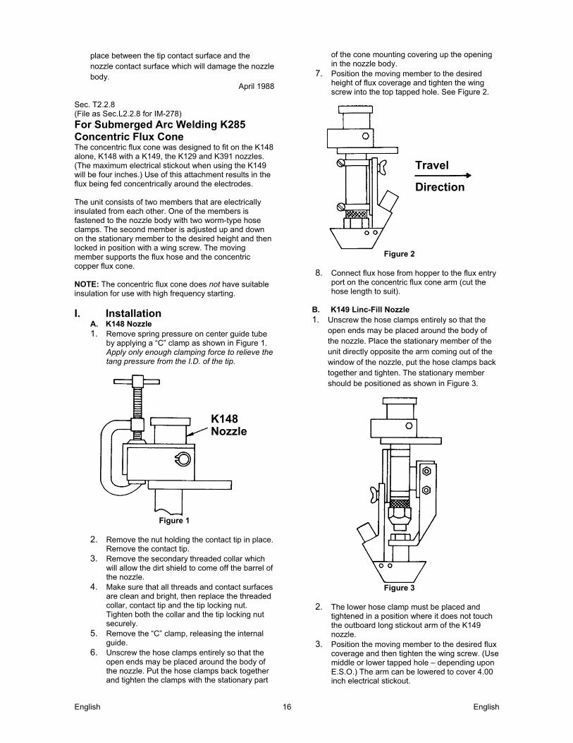
For Submerged Arc Welding K285 Concentric Flux Cone The concentric flux cone was designed to fit on the K148 alone, K148 with a K149, the K129 and K391 nozzles. (The maximum electrical stickout when using the K149 will be four inches.) Use of this attachment results in the flux being fed concentrically around the electrodes. The unit consists of two members that are electrically insulated from each other. One of the members is fastened to the nozzle body with two worm-type hose clamps. The second member is adjusted up and down on the stationary member to the desired height and then locked in position with a wing screw. The moving member supports the flux hose and the concentric copper flux cone. NOTE: The concentric flux cone does not have suitable insulation for use with high frequency starting.
I. Installation A. K148 Nozzle 1. Remove spring pressure on center guide tube
by applying a “C” clamp as shown in Figure 1. Apply only enough clamping force to relieve the tang pressure from the I.D. of the tip.
Figure 1
2. Remove the nut holding the contact tip in place.
Remove the contact tip. 3. Remove the secondary threaded collar which
will allow the dirt shield to come off the barrel of the nozzle.
4. Make sure that all threads and contact surfaces are clean and bright, then replace the threaded collar, contact tip and the tip locking nut. Tighten both the collar and the tip locking nut securely.
5. Remove the “C” clamp, releasing the internal guide.
6. Unscrew the hose clamps entirely so that the open ends may be placed around the body of the nozzle. Put the hose clamps back together and tighten the clamps with the stationary part
of the cone mounting covering up the opening in the nozzle body.
7. Position the moving member to the desired height of flux coverage and tighten the wing screw into the top tapped hole. See Figure 2.
Figure 2
8. Connect flux hose from hopper to the flux entry
port on the concentric flux cone arm (cut the hose length to suit).
B. K149 Linc-Fill Nozzle 1. Unscrew the hose clamps entirely so that the
open ends may be placed around the body of the nozzle. Place the stationary member of the unit directly opposite the arm coming out of the window of the nozzle, put the hose clamps back together and tighten. The stationary member should be positioned as shown in Figure 3.
Figure 3
2. The lower hose clamp must be placed and
tightened in a position where it does not touch the outboard long stickout arm of the K149 nozzle.
3. Position the moving member to the desired flux coverage and then tighten the wing screw. (Use middle or lower tapped hole – depending upon E.S.O.) The arm can be lowered to cover 4.00 inch electrical stickout.
Travel
Direction
K148Nozzle
English English 17
4. Connect flux hose from hopper to the flux entry
port on the concentric flux cone arm (cut the hose length to suit).
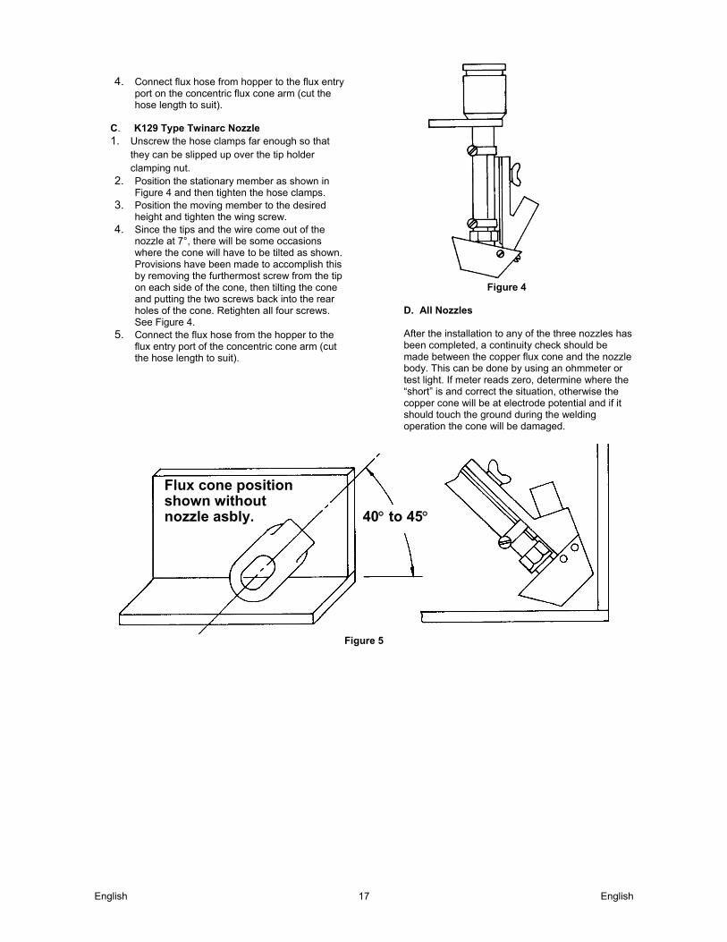
C. K129 Type Twinarc Nozzle 1. Unscrew the hose clamps far enough so that
they can be slipped up over the tip holder clamping nut.
2. Position the stationary member as shown in Figure 4 and then tighten the hose clamps.
3. Position the moving member to the desired height and tighten the wing screw.
4. Since the tips and the wire come out of the nozzle at 7°, there will be some occasions where the cone will have to be tilted as shown. Provisions have been made to accomplish this by removing the furthermost screw from the tip on each side of the cone, then tilting the cone and putting the two screws back into the rear holes of the cone. Retighten all four screws. See Figure 4.
5. Connect the flux hose from the hopper to the flux entry port of the concentric cone arm (cut the hose length to suit).
Figure 4
D. All Nozzles After the installation to any of the three nozzles has been completed, a continuity check should be made between the copper flux cone and the nozzle body. This can be done by using an ohmmeter or test light. If meter reads zero, determine where the “short” is and correct the situation, otherwise the copper cone will be at electrode potential and if it should touch the ground during the welding operation the cone will be damaged.
Figure 5
Flux cone position shown without nozzle asbly. 40 to 45

English English 18
Sec. T2.2.8, L2.2.8 and 2.7.8 (Continued)
II. General Operating Comments
A. Nozzle positions for Horizontal Fillets 1. K148 or K148 with K149.
After the concentric flux unit has been fastened to the nozzle body (per Section I, A or B), set the nozzle to the proper electrode angle dictated by the procedure. Loosen the two hold down clamps which fasten the nozzle to the face plate, rotate the entire nozzle assembly approximately 40 to 45 and then retighten the clamps. Inch the electrode out of the nozzle to the proper E.S.O. Position the wire into the joint configuration, then slide the concentric cone down so that it is approximately .12 of an inch away from the vertical and the horizontal surfaces to be welded. Tighten the wing screw. See Figure 5.
2. K129. After mounting the concentric cone to the nozzle (per Section I, C) set the head and nozzle for the proper electrode angle per procedural requirements. Inch the electrode out of the tips to the proper E.S.O. Place the nozzle into the welding position. Loosen the clamps and rotate the concentric flux cone unit approximately 40 to 45°. Retighten the clamps.Loosen wing screw, allowing the cone assembly to slide down within .12 of an inch of touching the piece to be welded. See Figure 5.
B. Flux Hopper Mounting for Horizontal Fillets For horizontal fillet welding the flux hopper will not function properly if it is fastened to the face plate of the NA-3 or NA-5. The hopper should be mounted directly above the flux entry of the concentric flux cone unit. Flux hose angles should be no greater than 35 from the vertical plane to insure good flux flow from hopper to cone.
C. Usage On Deep Narrow Grooved Welds For narrow deep groove welding it may be necessary to remove the copper cone from the moving arm.
February 1982
English English 19
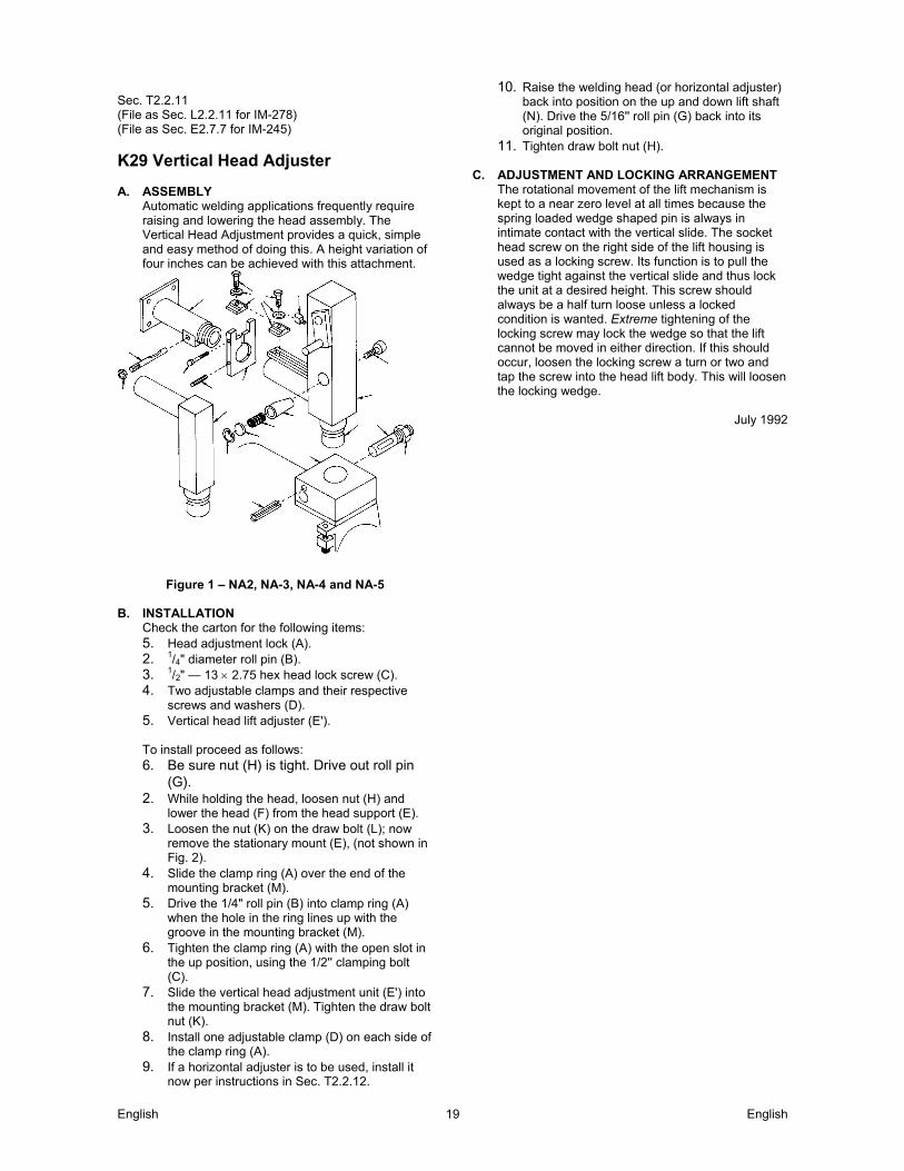
Sec. T2.2.11 (File as Sec. L2.2.11 for IM-278) (File as Sec. E2.7.7 for IM-245)
K29 Vertical Head Adjuster A. ASSEMBLY
Automatic welding applications frequently require raising and lowering the head assembly. The Vertical Head Adjustment provides a quick, simple and easy method of doing this. A height variation of four inches can be achieved with this attachment.
Figure 1 – NA2, NA-3, NA-4 and NA-5
B. INSTALLATION
Check the carton for the following items: 5. Head adjustment lock (A). 2. 1/4" diameter roll pin (B). 3. 1/2" — 13 2.75 hex head lock screw (C). 4. Two adjustable clamps and their respective
screws and washers (D). 5. Vertical head lift adjuster (E').
To install proceed as follows: 6. Be sure nut (H) is tight. Drive out roll pin
(G). 2. While holding the head, loosen nut (H) and
lower the head (F) from the head support (E). 3. Loosen the nut (K) on the draw bolt (L); now
remove the stationary mount (E), (not shown in Fig. 2).
4. Slide the clamp ring (A) over the end of the mounting bracket (M).
5. Drive the 1/4" roll pin (B) into clamp ring (A) when the hole in the ring lines up with the groove in the mounting bracket (M).
6. Tighten the clamp ring (A) with the open slot in the up position, using the 1/2'' clamping bolt (C).
7. Slide the vertical head adjustment unit (E') into the mounting bracket (M). Tighten the draw bolt nut (K).
8. Install one adjustable clamp (D) on each side of the clamp ring (A).
9. If a horizontal adjuster is to be used, install it now per instructions in Sec. T2.2.12.
10. Raise the welding head (or horizontal adjuster) back into position on the up and down lift shaft (N). Drive the 5/16'' roll pin (G) back into its original position.
11. Tighten draw bolt nut (H). C. ADJUSTMENT AND LOCKING ARRANGEMENT
The rotational movement of the lift mechanism is kept to a near zero level at all times because the spring loaded wedge shaped pin is always in intimate contact with the vertical slide. The socket head screw on the right side of the lift housing is used as a locking screw. Its function is to pull the wedge tight against the vertical slide and thus lock the unit at a desired height. This screw should always be a half turn loose unless a locked condition is wanted. Extreme tightening of the locking screw may lock the wedge so that the lift cannot be moved in either direction. If this should occur, loosen the locking screw a turn or two and tap the screw into the head lift body. This will loosen the locking wedge.
July 1992
English English 20
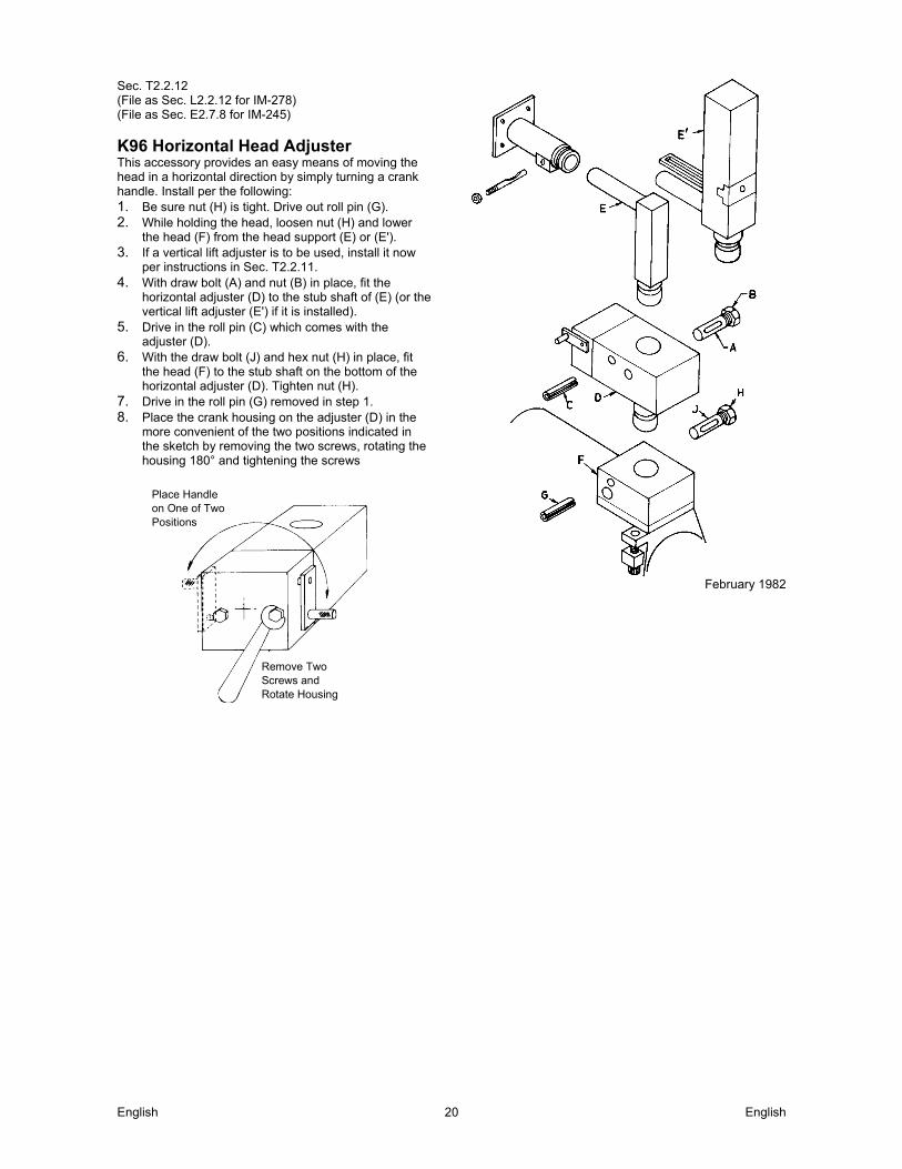
Sec. T2.2.12 (File as Sec. L2.2.12 for IM-278) (File as Sec. E2.7.8 for IM-245)
K96 Horizontal Head Adjuster This accessory provides an easy means of moving the head in a horizontal direction by simply turning a crank handle. Install per the following: 1. Be sure nut (H) is tight. Drive out roll pin (G). 2. While holding the head, loosen nut (H) and lower
the head (F) from the head support (E) or (E'). 3. If a vertical lift adjuster is to be used, install it now
per instructions in Sec. T2.2.11. 4. With draw bolt (A) and nut (B) in place, fit the
horizontal adjuster (D) to the stub shaft of (E) (or the vertical lift adjuster (E') if it is installed).
5. Drive in the roll pin (C) which comes with the adjuster (D).
6. With the draw bolt (J) and hex nut (H) in place, fit the head (F) to the stub shaft on the bottom of the horizontal adjuster (D). Tighten nut (H).
7. Drive in the roll pin (G) removed in step 1. 8. Place the crank housing on the adjuster (D) in the
more convenient of the two positions indicated in the sketch by removing the two screws, rotating the housing 180° and tightening the screws
February 1982
Place Handle on One of Two Positions
Remove Two Screws and Rotate Housing
English English 21
Electrical Installation Sec. T2.3.1
Wiring the Equipment
WARNING ELECTRIC SHOCK CAN KILL: Have an electrician install and
service this equipment. Turn the input power off at the fuse
box before working on equipment. Do not touch electrically hot parts.
A. INPUT POWER REQUIRED The only power required for operation of the control is 115 volts AC, 50 or 60 Hz. All power sources covered in Sec. T2.3.4 provide the required power. If there is no connection diagram available for a particular power source, the power source is not suitable for use with the NA-5. B. CONNECTION OF HEAD TO CONTROLS All heads include a 4-foot motor and motor tachometer cable. Insert the plugs on these cables into the matching receptacles on the side of the control box. If the control box is to be mounted so the 4-foot cables are not sufficient, install a K335 or K338 Control to Head Extension cable of the length ordered (up to 30 feet). The K335, for the NA-5S head, includes motor, tachometer and flux hopper lead extensions with polarized plugs on each end and electrode cables. The K338 for the NA-5N, NF, and SF heads, is the same as the K335 without the flux hopper lead extension. The NA-5N and NA-5S also include two 4-foot lengths of electrode cable. Bolt the terminals of one end of the cable pair to the wire contact assembly and the terminals of the other end to the electrode leads to the K215 Power Source to Control cable assembly. Properly insulate the bolted connection. When the K335 or K338 extension cables are used between the controls and heads, the 4-foot lengths of electrode cable are not used. If currents or duty cycle higher than 1000 amperes at 80% duty cycle will be used, add additional electrode cable per Table 1. The “F” models do not include the 4-foot lengths of electrode cable as standard. If not using a K335 or K338, for the NA-5NF or NA-5SF order an appropriate length of the needed electrode cable. Connect it between the wire contact assembly and the K215 cable assembly as described above. TABLE 1 80% Duty Cycle Below 1000 amps Two 4/0 1000 to 1300 amps Three 4/0 1300 to 1500 amps Four 4/0
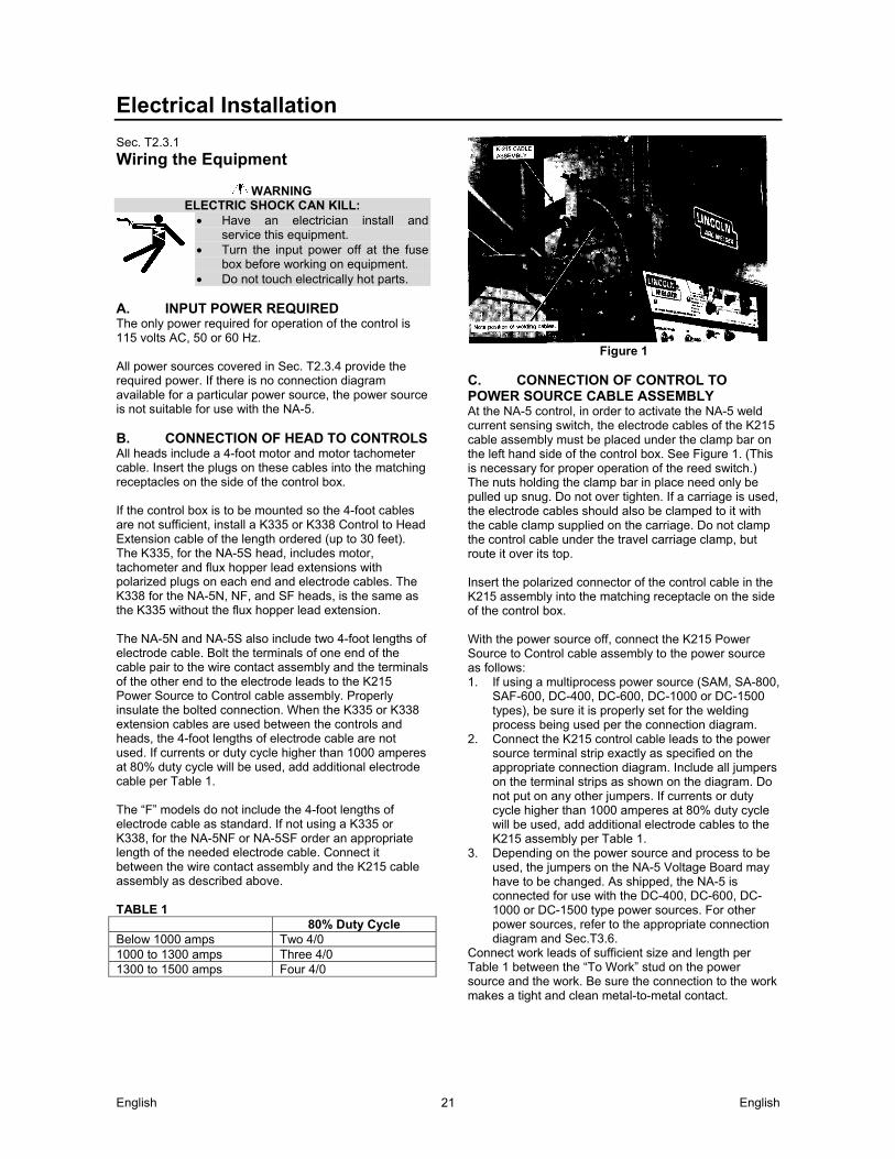
Figure 1
C. CONNECTION OF CONTROL TO POWER SOURCE CABLE ASSEMBLY At the NA-5 control, in order to activate the NA-5 weld current sensing switch, the electrode cables of the K215 cable assembly must be placed under the clamp bar on the left hand side of the control box. See Figure 1. (This is necessary for proper operation of the reed switch.) The nuts holding the clamp bar in place need only be pulled up snug. Do not over tighten. If a carriage is used, the electrode cables should also be clamped to it with the cable clamp supplied on the carriage. Do not clamp the control cable under the travel carriage clamp, but route it over its top. Insert the polarized connector of the control cable in the K215 assembly into the matching receptacle on the side of the control box. With the power source off, connect the K215 Power Source to Control cable assembly to the power source as follows: 1. If using a multiprocess power source (SAM, SA-800,
SAF-600, DC-400, DC-600, DC-1000 or DC-1500 types), be sure it is properly set for the welding process being used per the connection diagram.
2. Connect the K215 control cable leads to the power source terminal strip exactly as specified on the appropriate connection diagram. Include all jumpers on the terminal strips as shown on the diagram. Do not put on any other jumpers. If currents or duty cycle higher than 1000 amperes at 80% duty cycle will be used, add additional electrode cables to the K215 assembly per Table 1.
3. Depending on the power source and process to be used, the jumpers on the NA-5 Voltage Board may have to be changed. As shipped, the NA-5 is connected for use with the DC-400, DC-600, DC-1000 or DC-1500 type power sources. For other power sources, refer to the appropriate connection diagram and Sec.T3.6.
Connect work leads of sufficient size and length per Table 1 between the “To Work” stud on the power source and the work. Be sure the connection to the work makes a tight and clean metal-to-metal contact.
English English 22
Sec. T2.3.1 (Continued) D. ELECTRODE POLARITY Polarity is changed by operating the polarity switch on the power source if so equipped or by interchanging the welding leads on the power source output studs. IMPORTANT: WHEN CHANGING POLARITY ON IN- STALLATIONS USING THE DISCONTINUED K224 SOLID-STATE REMOTE CONTROL: Turn generator off and allow it to come to a complete stop before changing polarity. The polarity switch on the solid-state remote field control and the power source polarity must be set to the same polarity. Failure to do so will result in blowing the fuse in the solid-state remote field control and loss of generator output. The polarity of the NA-5 control circuit is shipped connected for electrode positive. If electrode negative is required, two leads inside the NA-5 control must be reversed. Proceed as follows: Turn off the input power to the NA-5 control box by turning off the welding power source. Open the control box door and locate the terminal strips mounted on the back of the box in the lower left hand corner. On the right end of the lower terminal strip, interchange the black and white leads going to the terminals marked (+) and (–). The black lead (No. 67) must be connected to the same polarity as the electrode welding lead, i.e. if the electrode is positive, connect the black lead to the (+) terminal on the terminal strip. The white lead (No. 21) is connected to the opposite polarity terminal. E. TRAVEL MECHANISM 115 volt AC power to drive the standard Lincoln travel carriage or for starting and stopping other travel mechanisms is obtained from a receptacle on the control box. This is a 4-prong receptacle connected to leads #531, #532, #25, and a grounding lead. Leads 531 and 532 are 115 volts AC. Leads #25 and #531 are 115 volts AC with #25 connected through the wire feeder travel switching circut for manual or automatic starting and stopping. (See Sec. T2.2.4-C for completed details on the K325 Travel Carriage.) F. ARC AND TRAVEL STARTING AND STOPPING Various sequences for starting and stopping the arc and travel are possible with standard machines or optional features. The choice of sequences depends upon the specific requirements of the procedures and application. See Sec. T3.5.2 for a description of these sequences and the needed reconnection instructions. G. SPEEDMETER CALIBRATION The jumper on the NA-5 Speedmeter board, located on the backside of the NA-5 door behind the digital speedmeter, is factory shipped connected to Pin “95” which is correct for a 95/1 NA-5 head ratio using the S12514 drive roll. For NA-5 heads with other ratios or drive rolls, the jumper must be reconnected per chart below:
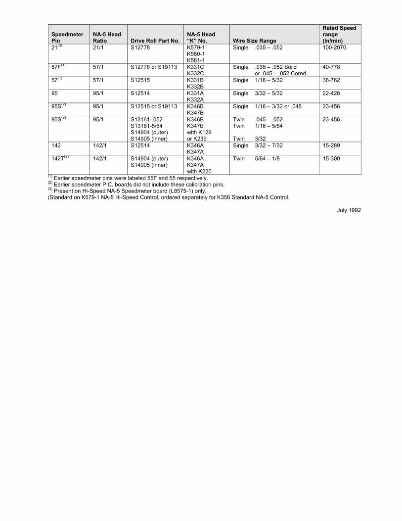
Speedmeter Pin
NA-5 Head Ratio Drive Roll Part No.
NA-5 Head “K” No. Wire Size Range
Rated Speed range (ln/min)
21(3) 21/1 S12778 K579-1 K580-1 K581-1
Single .035 – .052 100-2070
57F(1) 57/1 S12778 or S19113 K331C K332C
Single .035 – .052 Soild or .045 – .052 Cored
40-778
57(1) 57/1 S12515 K331B K332B
Single 1/16 – 5/32 38-762
95 95/1 S12514 K331A K332A
Single 3/32 – 5/32 22-428
95S(2) 95/1 S12515 or S19113 K346B K347B
Single 1/16 – 3/32 or .045 23-456
95S(2) 95/1 S13161-.052 S13161-5/64 S14904 (outer) S14905 (inner)
K346B K347B with K129 or K239
Twin .045 – .052 Twin 1/16 – 5/64 Twin 3/32
23-456
142 142/1 S12514 K346A K347A
Single 3/32 – 7/32 15-289
142T(2) 142/1 S14904 (outer) S14905 (inner)
K346A K347A with K225
Twin 5/64 – 1/8 15-300
(1) Earlier speedmeter pins were labeled 55F and 55 respectively. (2) Earlier speedmeter P.C. boards did not include these calibration pins. (3) Present on Hi-Speed NA-5 Speedmeter board (L8575-1) only. (Standard on K579-1 NA-5 Hi-Speed Control, ordered separately for K356 Standard NA-5 Control.
July 1992

Sec. T2.3.4-A
Connection of NA-5 (All) to a DC-600 CONNECTIONS MUST BE MADE EXACTLY AS SHOWN BELOW. FOR ANY OTHER USE OF POWER SOURCE, DISCONNECT ALL NA-5 LEADS AND CABLES.
NOTE: Above diagram shows electrode connected positive. To change polarity, turn power off, reverse the electrode and work cables at the power source and position the switch on power source to proper polarity. Refer to NA-5 operating manual for required NA-5 Control Box polarity connections.
Notes: N.A. On earlier DC-600’ s, #67 terminal was also on the terminal strip. N.B. Welding cables must be of proper capacity for the current and duty cycle of immediate and future applications.
N.C. Extend lead #21 using #14 or larger insulated wire physically suitable for the installation. An S16586-[] remote voltage sensing work lead is available for this purpose. Connect it directly to the work piece keeping it separate from the welding work cable connection to the work piece. For convenience, this extended #21 lead should be taped along the welding work cable.
N.D. Tape up bolted connection.
N.E. Connect the NA-5 control cable grounding lead to the frame terminal marked near the power source terminal strip. The power source must be properly grounded.
N.F. If using an older K215 control cable: Connect lead #75 to #75 on terminal strip, connect lead #76 to #76 on terminal strip, connect lead #77 to #77 on terminal strip. N.G. The jumpers on the NA-5 Voltage Board must be connected as follows: Connect red jumper to pin “ S” .
Connect white jumper to pin “ B” .
N.H. Connect a jumpers from “ N” to “ P” . There is no NPS terminal strip on DC-600 codes above 8200. N.J. For proper NA-5 operation, the electrode cables must be snugged under the clamp bar on the left side of the NA-5 Control Box. M13968
DC-600 - POWER SOURCE SETTINGS
ALL CODES: TURN OFF INPUT POWER
Adjust the Power Source: DC-600: 1. Connect electrode cables to terminal of desired
polarity. 2. Set toggle switch to same polarity as the electrode
cable connection. 3. Set toggle switch to “Remote”. 4. Set mode switch to the desired position for the
process to be used.
DC-600 CODES 8046 – 8200:
For Sub Arc:
1. Set mode switch to CV Sub Arc. 2. White lead on Control P.C. Board is
connected to Pin “ M” . For all Open Arc Processes Except NR-203 Electrodes:
1. Set mode switch to CV Innershield. 2. White lead on Control P.C. Board is
connected to Pin “ M” .
For NR-203 Electrodes:
1. Set mode switch to CV Innershield. 2. White lead on Control P.C. Board is
connected to Pin “ I” .
DC-600 CODES 800 – 8045:
For Sub Arc:
1. Set modes switch to CV Sub Arc. 2. White lead on Control P.C. Board is connected to
Pin “ M” and blue lead is connected to “ W” . For all Open Arc Processes Except NR-302 and NR-203 Electrodes:
1. Set mode switch to CV Innershield.
2. White lead on Control P.C. Board is connected to Pin “ M” and blue lead is connected to “ W” .
For NR-203 and NR-302 Electrodes:
1. Set mode switch to CV Innershield. 2. White lead on Control P.C. Board is
connected to Pin “ I” and blue lead is connected to “ S” .
DC-600 CODES ABOVE 8200:
For Sub Arc:
1. Set mode switch to CV Sub Arc.
For all Open Arc Processes:
1. Set mode switch to CV Innershield.
POWER SOURCE CONTROL CABLE N.G.
TO NA-5 INPUT CABLE PLUG
N.E.
N.A.
N.H.
NEGATIVE POSITIVE
N.C.&N.D.
N.D. & N.J.
BOLT TO CABLES FROM NA-
5 WIRE CONTACT
ASSEMBLY.
CONNECT TO WORK FOR OPTIMUM PERFORMANCE WITH THE NA-5, DC-600’S WITH CODES 8288 AND ABOVE ARE PREFERRED.FOR ADDITIONAL INSTALLLATION INSTRUCTIONS, SEE NA-5 OPERATION MANUL.
N.F.
N.B.
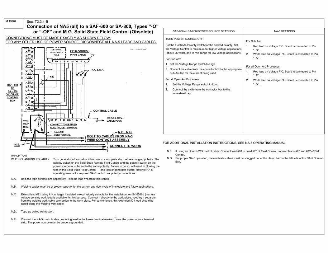
Sec. T2.3.4-B
Connection of NA5 (all) to a SAF-600 or SA-800, Types “-O” or “-OF” and M.G. Solid State Field Control (Obsolete) CONNECTIONS MUST BE MADE EXACTLY AS SHOWN BELOW. FOR ANY OTHER USE OF POWER SOURCE, DISCONNECT ALL NA-5 LEADS AND CABLES.
IMPORTANT WHEN CHANGING POLARITY: Turn generator off and allow it to come to a complete stop before changing polarity. The
polarity switch on the Solid-State Remote Field Control and the polarity switch on the power source must be set to the same polarity. Failure to do so, will result in blowing the fuse in the Solid-State Field Control – and loss of generator output. Refer to NA-5 operating manual for required NA-5 control box polarity connections.
N.A. Bolt and tape connections separately. Tape up lead #75 from field control.
N.B. Welding cables must be of proper capacity for the current and duty cycle of immediate and future applications.
N.C Extend lead #21 using #14 or larger insulated wire physically suitable for the installation. An S-16586-[ ] remote voltage-sensing work lead is available for this purpose. Connect it directly to the work piece, keeping it separate from the welding work cable connection to the work piece. For convenience, this extended #21 lead should be taped along the welding work cable.
N.D. Tape up bolted connection.
N.E. Connect the NA-5 control cable grounding lead to the frame terminal marked near the power source terminal strip. The power source must be properly grounded.
SAF-600 or SA-800 POWER SOURCE SETTINGS NA-5 SETTINGS
TURN POWER SOURCE OFF.
Set the Electrode Polarity switch for the desired polarity. Set the Voltage Control to maximum for higher voltage applications (above 25 volts), and to mid-range for low voltage applications.
For Sub Arc:
1. Set the Voltage Range switch to High.
2. Connect the cable from the contactor box to the appropriate Sub Arc tap for the current being used.
For all Open Arc Processes:
1. Set the Voltage Range switch to Low.
2. Connect the cable from the contactor box to the Innershield tap.
For Sub Arc:
1. Red lead on Voltage P.C. Board is connected to Pin “ S” .
2. White lead on Voltage P.C. Board is connected to Pin “ A” .
For all Open Arc Processes:
1. Red lead on Voltage P.C. Board is connected to Pin “ F” .
2. White lead on Voltage P.C. Board is connected to Pin “ A” .
FOR ADDITIONAL INSTALLATION INSTRUCTIONS, SEE NA-5 OPERATING MANUAL
N.F. If using an older K-215 control cable: Connect lead #76 to Lead #76 of Field Control, connect leads #75 and #77 of Field Control.
N.G. For proper NA-5 operation, the electrode cables must be snugged under the clamp bar on the left side of the NA-5 Control Box.
M 13984
FIELD CONTROL
INPUT CABLE
N.A. & N.F.
CONTROL CABLE
TO NA-5 INPUT CABLE PLUG
N.D., N.G.
CONNECT TO WORK
BOLT TO CABLES FROM NA-5WIRE CONTACT ASSEMBLY
OPTIONAL
SOLID STATE
FIELD
CONTROL
SAF - 600 OR
SA – 800 "O" OR "OF"
CONTROL BOX
N.E
AUTO.
EQUIP.
TERM. CONNECT TO DESIRED ELECTRODE TERMINAL
N.C. & N.D.
WORK TERMINAL
N.B
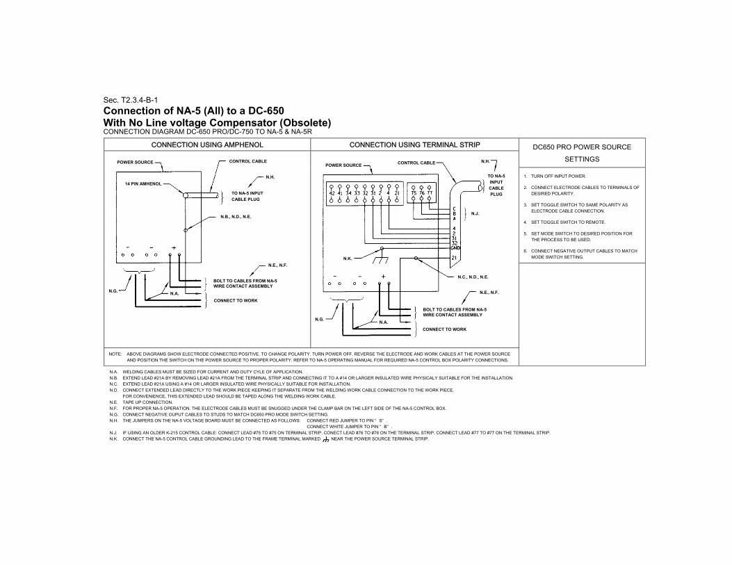
Sec. T2.3.4-B-1
Connection of NA-5 (All) to a DC-650 With No Line voltage Compensator (Obsolete) CONNECTION DIAGRAM DC-650 PRO/DC-750 TO NA-5 & NA-5R
CONNECTION USING AMPHENOL CONNECTION USING TERMINAL STRIP DC650 PRO POWER SOURCE SETTINGS
1. TURN OFF INPUT POWER.
2. CONNECT ELECTRODE CABLES TO TERMINALS OF DESIRED POLARITY.
3. SET TOGGLE SWITCH TO SAME POLARITY AS ELECTRODE CABLE CONNECTION.
4. SET TOGGLE SWITCH TO REMOTE.
5. SET MODE SWITCH TO DESIRED POSITION FOR THE PROCESS TO BE USED.
6. CONNECT NEGATIVE OUTPUT CABLES TO MATCH MODE SWITCH SETTING.
NOTE: ABOVE DIAGRAMS SHOW ELECTRODE CONNECTED POSITIVE. TO CHANGE POLARITY. TURN POWER OFF. REVERSE THE ELECTRODE AND WORK CABLES AT THE POWER SOURCE AND POSITION THE SWITCH ON THE POWER SOURCE TO PROPER POLARITY. REFER TO NA-5 OPERATING MANUAL FOR REQUIRED NA-5 CONTROL BOX POLARITY CONNECTIONS.
N.A. WELDING CABLES MUST BE SIZED FOR CURRENT AND DUTY CYLE OF APPLICATION. N.B. EXTEND LEAD #21A BY REMOVING LEAD #21A FROM THE TERMINAL STRIP AND CONNECTING IT TO A #14 OR LARGER INSULATED WIRE PHYSICALY SUITABLE FOR THE INSTALLATION. N.C. EXTEND LEAD #21A USING A #14 OR LARGER INSULATED WIRE PHYSICALLY SUITABLE FOR INSTALLATION. N.D. CONNECT EXTENDED LEAD DIRECTLY TO THE WORK PIECE KEEPING IT SEPARATE FROM THE WELDING WORK CABLE CONNECTION TO THE WORK PIECE.
FOR CONVENIENCE, THIS EXTENDED LEAD SHOULD BE TAPED ALONG THE WELDING WORK CABLE. N.E. TAPE UP CONNECTION. N.F. FOR PROPER NA-5 OPERATION. THE ELECTRODE CABLES MUST BE SNUGGED UNDER THE CLAMP BAR ON THE LEFT SIDE OF THE NA-5 CONTROL BOX. N.G. CONNECT NEGATIVE OUPUT CABLES TO STUDS TO MATCH DC650 PRO MODE SWITCH SETTING. N.H. THE JUMPERS ON THE NA-5 VOLTAGE BOARD MUST BE CONNECTED AS FOLLOWS: CONNECT RED JUMPER TO PIN “ S” .
CONNECT WHITE JUMPER TO PIN “ B” . N.J. IF USING AN OLDER K-215 CONTROL CABLE: CONNECT LEAD #75 TO #75 ON TERMINAL STRIP, CONECT LEAD #76 TO #76 ON THE TERMINAL STRIP, CONNECT LEAD #77 TO #77 ON THE TERMINAL STRIP. N.K. CONNECT THE NA-5 CONTROL CABLE GROUNDING LEAD TO THE FRAME TERMINAL MARKED NEAR THE POWER SOURCE TERMINAL STRIP.
N.B., N.D., N.E.
TO NA-5 INPUT
CABLE PLUG
CONTROL CABLE POWER SOURCE
N.E., N.F.
N.G.
BOLT TO CABLES FROM NA-5 WIRE CONTACT ASSEMBLY
CONNECT TO WORK
POWER SOURCE CONTROL CABLE
TO NA-5
INPUT
CABLE
PLUG
BOLT TO CABLES FROM NA-5 WIRE CONTACT ASSEMBLY
CONNECT TO WORK
N.G. N.A.
N.K.
N.J.
N.H.
N.C., N.D., N.E.
N.E., N.F.
14 PIN AMHENOL
N.H.
N.A.

Sec. T2.3.4-C
Connection of NA-5 (All) to R3S-400, -600 or -800 With no line voltage Compensator (Obsolete) CONNECTIONS MUST BE MADE EXACTLY AS SHOWN BELOW. FOR ANY OTHER USE OF POWER SOURCE, DISCONNECT ALL NA-5 LEADS AND CABLES
NOTE: Above diagram shows electrode connected positive. To change polarity, turn power off, reverse the
electrode and work cables at the power source and position the switch on power source to proper polarity. Refer to NA-5 operating manual for required NA-5 control box polarity connections.
N.A. Add jumper from #75 to #76, using insulated copper wire.
N.B. Welding cables must be of proper capacity for the current and duty cycle of immediate and future applications.
N.C. Extend lead #21 using #14 or larger insulated wire physically suitable for the installation. An S-16586-[ ] remote voltage-sensing work lead is available for this purpose. Connect it directly to the work piece, keeping it separate from the welding work cable connection to the work piece. For convenience, this extended #21 lead should be taped along the welding work cable.
N.D. Tape up bolted connection.
N.E. Connect the NA-5 control cable grounding lead to the frame terminal marked , near the power source terminal strip. The power source must be properly grounded.
R3S POWER SOURCE SETTINGS NA-5 SETTINGS
TURN POWER SOURCE OFF.
For all processes: 1. Connect electrode cable to terminal of desired polarity. 2. Set the Polarity Switch to the same polarity as the electrode
cable connection. 3. Set toggle switch to Remote. 4. Install voltage triangle in a position as close as possible to the
desired arc voltage.
For Sub Arc:
1. Red lead on Voltage P.C. Board is connected to Pin “S”.
2. White lead on Voltage P.C. Board is connected to Pin “A”.
For all Open Arc Processes:
1. Red lead on Voltage P.C. Board is connected to Pin “F”.
2. White lead on Voltage P.C. Board is connected to Pin “A”.
FOR ADDITIONAL INSTALLATION INSTRUCTIONS, SEE NA-5 OPERATING MANUAL
N.F. If using an older K-215 control cable: Connect lead #75 to #75 on terminal strip, connect lead #76 to #77 on terminal strip, connect lead #77 to #76 on terminal strip, and add jumper per N.A.
N.G. On earlier R3S machines, #67 and #1 terminals were also on the terminal strip.
N.H. The upper terminal strip (#75, #76, #77) was not present on early R3S machines. Those machines are not compatible with the NA-5, since there can be no adjustment of voltage by the NA-5.
N.J. For proper NA-5 operation, the electrode cables must be snugged under the clamp bar on the left side of the NA-5 Control Box.
M13985
CONTROL CABLE
TO NA-5 INPUT
CABLE PLUG
POWER SOURCE
N.H.
N.A.
N.G.
N.B.
N.F.
NEGATIVE POSITIVE N.D. & N.J.
BOLT TO CABLES FROM NA-5
WIRE CONTACT ASSEMBLY.
CONNECT TO WORK
N.E.
N.C. & N.D.
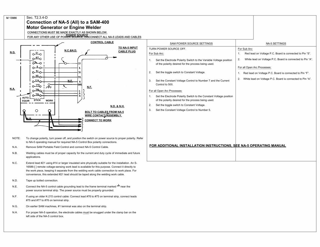
NOTE: To change polarity, turn power off, and position the switch on power source to proper polarity. Refer
to NA-5 operating manual for required NA-5 Control Box polarity connections.
N.A. Remove SAM Portable Field Control and connect NA-5 Control Cable.
N.B. Welding cables must be of proper capacity for the current and duty cycle of immediate and future applications.
N.C. Extend lead #21 using #14 or larger insulated wire physically suitable for the installation. An S-16586-[ ] remote voltage-sensing work lead is available for this purpose. Connect it directly to the work piece, keeping it separate from the welding work cable connection to work place. For convenience, this extended #21 lead should be taped along the welding work cable.
N.D. Tape up bolted connection.
N.E. Connect the NA-5 control cable grounding lead to the frame terminal marked near the power source terminal strip. The power source must be properly grounded.
N.F. If using an older K-215 control cable: Connect lead #76 to #75 on terminal strip, connect leads #75 and #77 to #76 on terminal strip.
N.G. On earlier SAM machines, #1 terminal was also on the terminal strip.
N.H. For proper NA-5 operation, the electrode cables must be snugged under the clamp bar on the left side of the NA-5 control box.
M 13986 Sec. T2.3.4-D
Connection of NA-5 (All) to a SAM-400 Motor Generator or Engine Welder CONNECTIONS MUST BE MADE EXACTLY AS SHOWN BELOW. FOR ANY OTHER USE OF POWER SOURCE, DISCONNECT ALL NA-5 LEADS AND CABLES
SAM POWER SOURCE SETTINGS NA-5 SETTINGS
TURN POWER SOURCE OFF. For Sub Arc:
1. Set the Electrode Polarity Switch to the Variable Voltage position of the polarity desired for the process being used.
2. Set the toggle switch to Constant Voltage.
3. Set the Constant Voltage Control to Number 7 and the Current Control to 500.
For all Open Arc Processes:
1. Set the Electrode Polarity Switch to the Constant Voltage position of the polarity desired for the process being used.
2. Set the toggle switch to Constant Voltage.
3. Set the Constant Voltage Control to Number 5.
For Sub Arc: 1. Red lead on Voltage P.C. Board is connected to Pin “S”.
2. White lead on Voltage P.C. Board is connected to Pin “A”.
For all Open Arc Processes;
1. Red lead on Voltage P.C. Board is connected to Pin “F”.
2. White lead on Voltage P.C. Board is connected to Pin “A”.
FOR ADDITIONAL INSTALLATION INSTRUCTIONS, SEE NA-5 OPERATING MANUAL
CONTROL CABLE
TO NA-5 INPUT
CABLE PLUG
POWER SOURCE
N.G.
N.D. & N.H.
BOLT TO CABLES FROM NA-5 WIRE CONTACT ASSEMBLY.
CONNECT TO WORK
N.A.
N.B.
N.C.&N.D.
N.F.
N.E.
AUTO. EQUIR STICK WORK
NOTE: To change polarity, turn power off, and position the switch on power source to proper polarity. Refer to NA-5 operating manual for required NA-5 Control Box polarity connections.
N.A. Remove SAM Portable Field Control and connect NA-5 Control Cable.
N.B. Welding cables must be of proper capacity for the current and duty cycle of immediate and future applications.
N.C. Extend lead #21 using #14 or larger insulated wire physically suitable for the installation. An S-16586-[ ] remote voltage-sensing work lead is available for this purpose. Connect it directly to the work piece, keeping it separate from the welding work cable connection to the work piece. For convenience, this extended #21 lead should be taped along the welding work cable.
N.D. Tape up bolted connection.
N.E. Connect the NA-5 control cable grounding lead to the frame terminal marked , near the power source terminal strip. The power source must be properly grounded.
N.F. If using an older K-215 control cable: Connect lead #76 to #75 on terminal strip, connect leads #75 and #77 to #76 on terminal strip.
N.G. On earlier SAM machines, #1 terminal was also on the terminal strip.
N.H. For proper NA-5 operation, the electrode cables must be snugged under the clamp bar on the left side of the NA-5 control box.
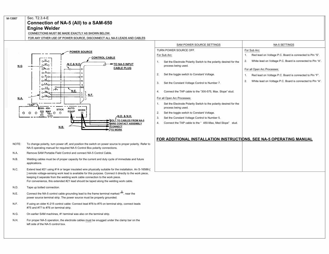
M-13987 Sec. T2.3.4-E
Connection of NA-5 (All) to a SAM-650 Engine Welder CONNECTIONS MUST BE MADE EXACTLY AS SHOWN BELOW. FOR ANY OTHER USE OF POWER SOURCE, DISCONNECT ALL NA-5 LEADS AND CABLES
SAM POWER SOURCE SETTINGS NA-5 SETTINGS
TURN POWER SOURCE OFF. For Sub Arc:
1. Set the Electrode Polarity Switch to the polarity desired for the process being used.
2. Set the toggle switch to Constant Voltage.
3. Set the Constant Voltage Control to Number 7.
4. Connect the TAP cable to the “300-575, Max. Slope” stud.
For all Open Arc Processes:
1. Set the Electrode Polarity Switch to the polarity desired for the process being used.
2. Set the toggle switch to Constant Voltage.
3. Set the Constant Voltage Control to Number 5.
4. Connect the TAP cable to the “ 450-Max, Med Slope” stud.
For Sub Arc: 1. Red lead on Voltage P.C. Board is connected to Pin “S”.
2. White lead on Voltage P.C. Board is connected to Pin “A”.
For all Open Arc Processes;
1. Red lead on Voltage P.C. Board is connected to Pin “F”.
2. White lead on Voltage P.C. Board is connected to Pin “A”.
FOR ADDITIONAL INSTALLATION INSTRUCTIONS, SEE NA-5 OPERATING MANUAL
CONTROL CABLE
TO NA-5 INPUT
CABLE PLUG
POWER SOURCE
N.G
N.D. & N.H.
BOLT TO CABLES FROM NA-5 WIRE CONTACT ASSEMBLY CONNECT TO WORK
N.A.
N.B.
N.C.& N.D.
N.F.
N.E.
AUTO. EQUIP
STICK WORK
"TAP"
MAX SLOPE
MED SLOPE
450-MAX
300-575
Sec. T2.3.4-F
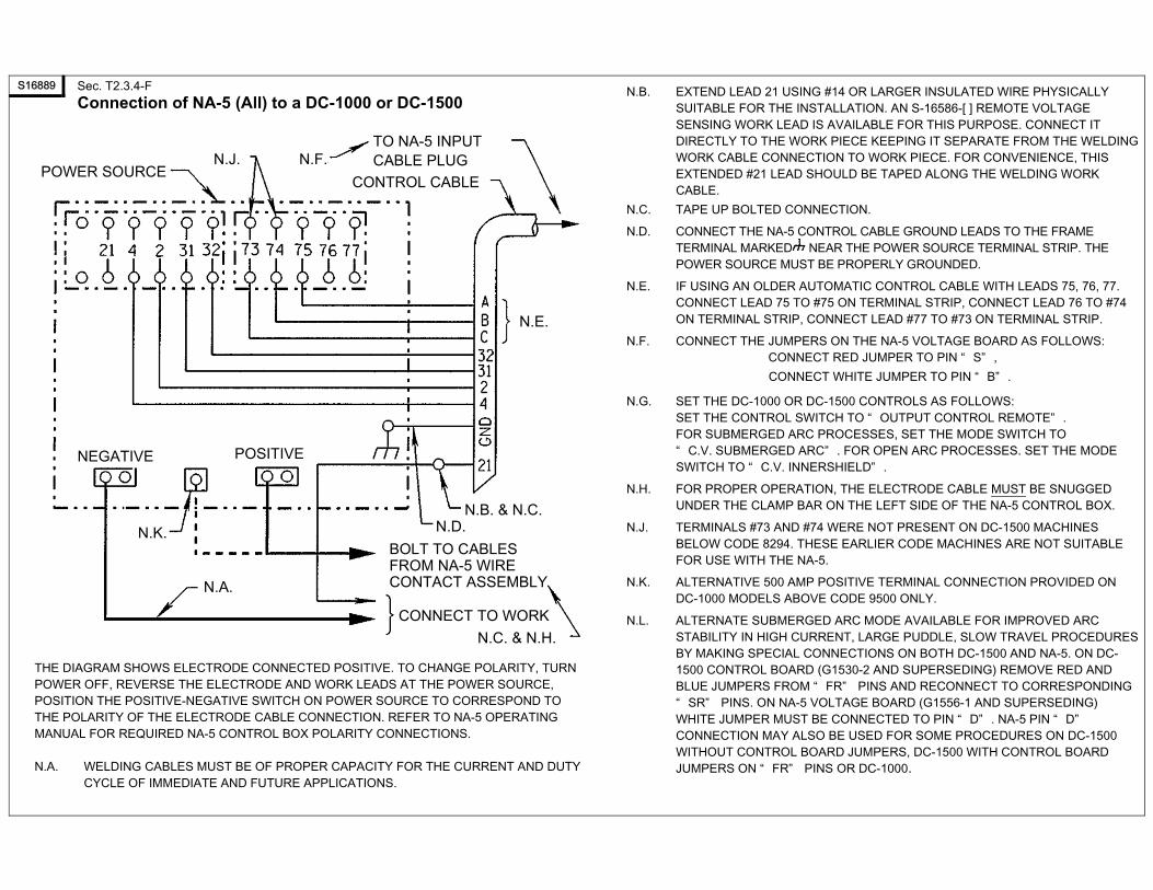
Connection of NA-5 (All) to a DC-1000 or DC-1500
THE DIAGRAM SHOWS ELECTRODE CONNECTED POSITIVE. TO CHANGE POLARITY, TURN POWER OFF, REVERSE THE ELECTRODE AND WORK LEADS AT THE POWER SOURCE, POSITION THE POSITIVE-NEGATIVE SWITCH ON POWER SOURCE TO CORRESPOND TO THE POLARITY OF THE ELECTRODE CABLE CONNECTION. REFER TO NA-5 OPERATING MANUAL FOR REQUIRED NA-5 CONTROL BOX POLARITY CONNECTIONS.
N.A. WELDING CABLES MUST BE OF PROPER CAPACITY FOR THE CURRENT AND DUTY CYCLE OF IMMEDIATE AND FUTURE APPLICATIONS.
N.B. EXTEND LEAD 21 USING #14 OR LARGER INSULATED WIRE PHYSICALLY SUITABLE FOR THE INSTALLATION. AN S-16586-[ ] REMOTE VOLTAGE SENSING WORK LEAD IS AVAILABLE FOR THIS PURPOSE. CONNECT IT DIRECTLY TO THE WORK PIECE KEEPING IT SEPARATE FROM THE WELDING WORK CABLE CONNECTION TO WORK PIECE. FOR CONVENIENCE, THIS EXTENDED #21 LEAD SHOULD BE TAPED ALONG THE WELDING WORK CABLE.
N.C. TAPE UP BOLTED CONNECTION.
N.D. CONNECT THE NA-5 CONTROL CABLE GROUND LEADS TO THE FRAME TERMINAL MARKED NEAR THE POWER SOURCE TERMINAL STRIP. THE POWER SOURCE MUST BE PROPERLY GROUNDED.
N.E. IF USING AN OLDER AUTOMATIC CONTROL CABLE WITH LEADS 75, 76, 77. CONNECT LEAD 75 TO #75 ON TERMINAL STRIP, CONNECT LEAD 76 TO #74 ON TERMINAL STRIP, CONNECT LEAD #77 TO #73 ON TERMINAL STRIP.
N.F. CONNECT THE JUMPERS ON THE NA-5 VOLTAGE BOARD AS FOLLOWS: CONNECT RED JUMPER TO PIN “ S” ,
CONNECT WHITE JUMPER TO PIN “ B” .
N.G. SET THE DC-1000 OR DC-1500 CONTROLS AS FOLLOWS: SET THE CONTROL SWITCH TO “ OUTPUT CONTROL REMOTE” . FOR SUBMERGED ARC PROCESSES, SET THE MODE SWITCH TO “ C.V. SUBMERGED ARC” . FOR OPEN ARC PROCESSES. SET THE MODE SWITCH TO “ C.V. INNERSHIELD” .
N.H. FOR PROPER OPERATION, THE ELECTRODE CABLE MUST BE SNUGGED UNDER THE CLAMP BAR ON THE LEFT SIDE OF THE NA-5 CONTROL BOX.
N.J. TERMINALS #73 AND #74 WERE NOT PRESENT ON DC-1500 MACHINES BELOW CODE 8294. THESE EARLIER CODE MACHINES ARE NOT SUITABLE FOR USE WITH THE NA-5.
N.K. ALTERNATIVE 500 AMP POSITIVE TERMINAL CONNECTION PROVIDED ON DC-1000 MODELS ABOVE CODE 9500 ONLY.
N.L. ALTERNATE SUBMERGED ARC MODE AVAILABLE FOR IMPROVED ARC STABILITY IN HIGH CURRENT, LARGE PUDDLE, SLOW TRAVEL PROCEDURES BY MAKING SPECIAL CONNECTIONS ON BOTH DC-1500 AND NA-5. ON DC-1500 CONTROL BOARD (G1530-2 AND SUPERSEDING) REMOVE RED AND BLUE JUMPERS FROM “ FR” PINS AND RECONNECT TO CORRESPONDING “ SR” PINS. ON NA-5 VOLTAGE BOARD (G1556-1 AND SUPERSEDING) WHITE JUMPER MUST BE CONNECTED TO PIN “ D” . NA-5 PIN “ D” CONNECTION MAY ALSO BE USED FOR SOME PROCEDURES ON DC-1500 WITHOUT CONTROL BOARD JUMPERS, DC-1500 WITH CONTROL BOARD JUMPERS ON “ FR” PINS OR DC-1000.
S16889
POWER SOURCE
TO NA-5 INPUT CABLE PLUG
CONTROL CABLE
N.F. N.J.
N.E.
N.B. & N.C.N.D.
POSITIVE NEGATIVE
N.A.
N.K. BOLT TO CABLES FROM NA-5 WIRE CONTACT ASSEMBLY
CONNECT TO WORK
N.C. & N.H.
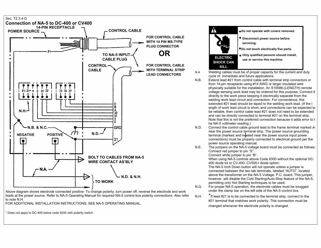
Sec. T2.3.4-G
Connection of NA-5 to DC-400 or CV400
Above diagram shows electrode connected positive. To change polarity, turn power off, reverse the electrode and work leads at the power source. Refer to NA-5 Operating Manual for required NA-5 control box polarity connections. Also refer to note N.H. FOR ADDITIONAL INSTALLATION INSTRUCTIONS, SEE NA-5 OPERATING MANUAL.
* Does not apply to DC-400 below code 9200 with polarity switch.
N.A Welding cables must be of proper capacity for the current and duty cycle of immediate and future applications. N.B. Extend lead #21 from control cable with terminal strip connectors or from 14-pin receptacle using #14 AWG or larger insulated wire physically suitable for the installation. An S16586-(LENGTH) remote voltage sensing work lead may be ordered for this purpose. Connect it directly to the work piece keeping it electrically separate from the welding work lead circuit and connection. For convenience, this extended #21 lead should be taped to the welding work lead. (If the l ength of work lead circuit is short, and connections can be expected to be reliable, then control cable lead #21 does not need to be extended and can be directly connected to terminal #21 on the terminal strip. Note that this is not the preferred connection because it adds error to t he NA-5 voltmeter reading.) N.D. Connect the control cable ground lead to the frame terminal marked near the power source terminal strip. The power source grounding terminal (marked and located near the power source input power connections) must be properly connected to electrical ground per the power source operating manual. N.E. The jumpers on the NA-5 voltage board must be connected as follows: Connect red jumper to pin “S”. Connect white jumper to pin “B”. When using NA-5 controls above Code 8300 without the optional DC- 400 diode kit or CV-400. CV500-I diode option: The NA-5 Inch Down button will not operate unless a jumper is connected between the two tab terminals, labeled “AUTO”, located above the transformer on the NA-5 Voltage. P.C. board. This jumper, however, will disable the Cold Starting/Auto-Stop feature of the NA-5, permitting only Hot Starting techniques to be used. N.G. For proper NA-5 operation, the electrode cables must be snugged under the clamp bar on the left side of the NA-5 control box.
N.H. *If lead #21 is to be connected to the terminal strip, connect to the #21 terminal that matches work polarity. This connection must be
changed whenever the electrode polarity is changed.
14-PIN RECEPTACLE CONTROL CABLE
FOR CONTROL CABLE WITH 14 PIN MS-TYPE PLUG CONNECTOR
FOR CONTROL CABLE WITH TERMINAL STRIP LEAD CONNECTORS
TO NA-5 INPUT CABLE PLUG
CONTROL CABLE
POWER SOURCE
BOLT TO CABLES FROM NA-5 WIRE CONTACT AS’BLY
N.D. & N.H. TO WORK
N.D.
N.A.
N.B. & N.C.
N.H.
NEGATIVE POSITIVE
OR
Do not operate with covers removed.
Disconnect power source before
servicing.
Do not touch electrically five parts.
Only qualified persons should install,
use or service this machine.
WARNING
ELECTRIC SHOCK CAN
KILL
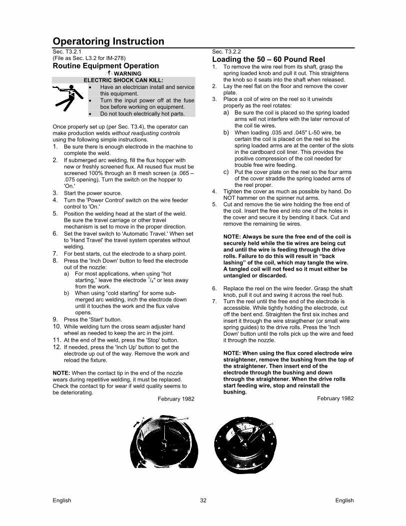
English English 32
Operatoring Instruction Sec. T3.2.1 (File as Sec. L3.2 for IM-278)
Routine Equipment Operation WARNING
ELECTRIC SHOCK CAN KILL: Have an electrician install and service
this equipment. Turn the input power off at the fuse
box before working on equipment. Do not touch electrically hot parts.
Once properly set up (per Sec. T3.4), the operator can make production welds without readjusting controls using the following simple instructions. 1. Be sure there is enough electrode in the machine to
complete the weld. 2. If submerged arc welding, fill the flux hopper with
new or freshly screened flux. All reused flux must be screened 100% through an 8 mesh screen (a .065 – .075 opening). Turn the switch on the hopper to 'On.'
3. Start the power source. 4. Turn the 'Power Control' switch on the wire feeder
control to 'On.' 5. Position the welding head at the start of the weld.
Be sure the travel carriage or other travel mechanism is set to move in the proper direction.
6. Set the travel switch to 'Automatic Travel.' When set to 'Hand Travel' the travel system operates without welding.
7. For best starts, cut the electrode to a sharp point. 8. Press the 'Inch Down' button to feed the electrode
out of the nozzle: a) For most applications, when using “hot
starting,” leave the electrode 1/4" or less away from the work.
b) When using “cold starting” for some sub- merged arc welding, inch the electrode down until it touches the work and the flux valve opens.
9. Press the 'Start' button. 10. While welding turn the cross seam adjuster hand
wheel as needed to keep the arc in the joint. 11. At the end of the weld, press the 'Stop' button. 12. If needed, press the 'Inch Up' button to get the
electrode up out of the way. Remove the work and reload the fixture.
NOTE: When the contact tip in the end of the nozzle wears during repetitive welding, it must be replaced. Check the contact tip for wear if weld quality seems to be deteriorating.
February 1982
Sec. T3.2.2
Loading the 50 – 60 Pound Reel 1. To remove the wire reel from its shaft, grasp the
spring loaded knob and pull it out. This straightens the knob so it seats into the shaft when released.
2. Lay the reel flat on the floor and remove the cover plate.
3. Place a coil of wire on the reel so it unwinds properly as the reel rotates: a) Be sure the coil is placed so the spring loaded
arms will not interfere with the later removal of the coil tie wires.
b) When loading .035 and .045" L-50 wire, be certain the coil is placed on the reel so the spring loaded arms are at the center of the slots in the cardboard coil liner. This provides the positive compression of the coil needed for trouble free wire feeding.
c) Put the cover plate on the reel so the four arms of the cover straddle the spring loaded arms of the reel proper.
4. Tighten the cover as much as possible by hand. Do NOT hammer on the spinner nut arms.
5. Cut and remove the tie wire holding the free end of the coil. Insert the free end into one of the holes in the cover and secure it by bending it back. Cut and remove the remaining tie wires.
NOTE: Always be sure the free end of the coil is securely held while the tie wires are being cut and until the wire is feeding through the drive rolls. Failure to do this will result in “back lashing” of the coil, which may tangle the wire. A tangled coil will not feed so it must either be untangled or discarded.
6. Replace the reel on the wire feeder. Grasp the shaft
knob, pull it out and swing it across the reel hub. 7. Turn the reel until the free end of the electrode is
accessible. While tightly holding the electrode, cut off the bent end. Straighten the first six inches and insert it through the wire straigthener (or small wire spring guides) to the drive rolls. Press the 'Inch Down' button until the rolls pick up the wire and feed it through the nozzle.
NOTE: When using the flux cored electrode wire straightener, remove the bushing from the top of the straightener. Then insert end of the electrode through the bushing and down through the straightener. When the drive rolls start feeding wire, stop and reinstall the bushing.
February 1982
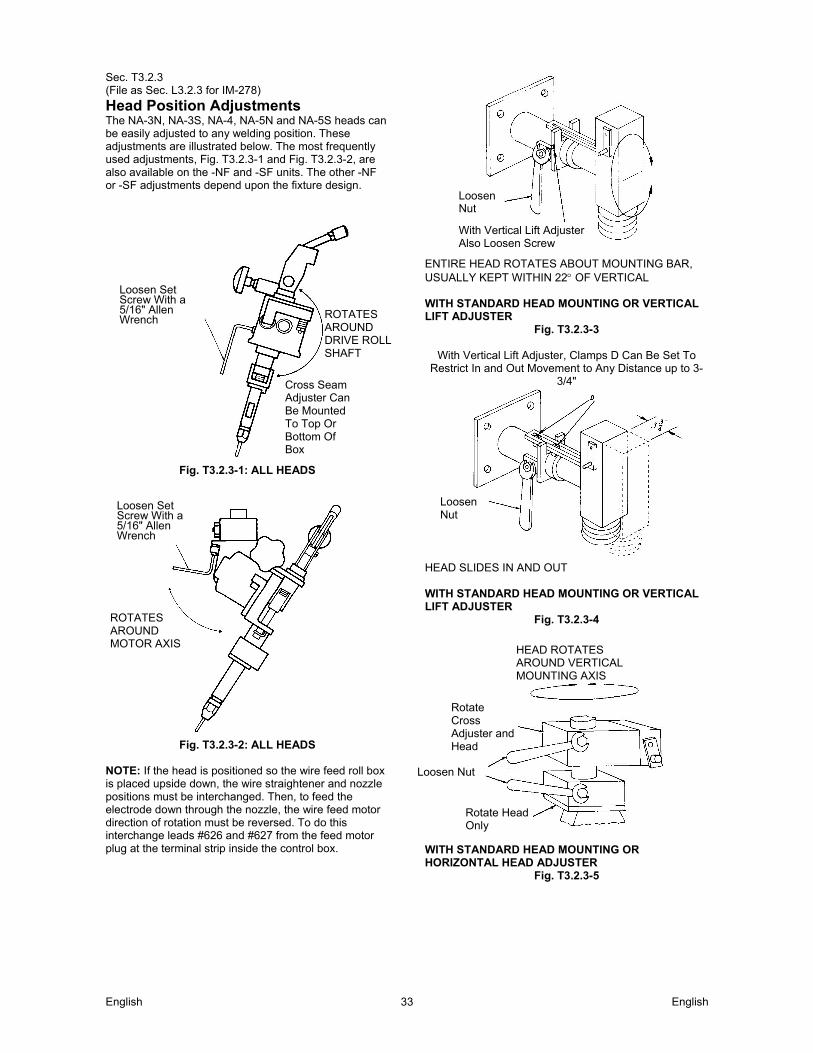
English English 33
Sec. T3.2.3 (File as Sec. L3.2.3 for IM-278)
Head Position Adjustments The NA-3N, NA-3S, NA-4, NA-5N and NA-5S heads can be easily adjusted to any welding position. These adjustments are illustrated below. The most frequently used adjustments, Fig. T3.2.3-1 and Fig. T3.2.3-2, are also available on the -NF and -SF units. The other -NF or -SF adjustments depend upon the fixture design.
Fig. T3.2.3-1: ALL HEADS
Fig. T3.2.3-2: ALL HEADS
NOTE: If the head is positioned so the wire feed roll box is placed upside down, the wire straightener and nozzle positions must be interchanged. Then, to feed the electrode down through the nozzle, the wire feed motor direction of rotation must be reversed. To do this interchange leads #626 and #627 from the feed motor plug at the terminal strip inside the control box.
ENTIRE HEAD ROTATES ABOUT MOUNTING BAR, USUALLY KEPT WITHIN 22 OF VERTICAL WITH STANDARD HEAD MOUNTING OR VERTICAL LIFT ADJUSTER
Fig. T3.2.3-3
With Vertical Lift Adjuster, Clamps D Can Be Set To Restrict In and Out Movement to Any Distance up to 3-
3/4"
HEAD SLIDES IN AND OUT WITH STANDARD HEAD MOUNTING OR VERTICAL LIFT ADJUSTER
Fig. T3.2.3-4
WITH STANDARD HEAD MOUNTING OR HORIZONTAL HEAD ADJUSTER
Fig. T3.2.3-5
Loosen Set Screw With a 5/16" Allen Wrench ROTATES
AROUND DRIVE ROLL SHAFT
Cross Seam Adjuster Can Be Mounted To Top Or Bottom Of Box
Loosen Set Screw With a 5/16" Allen Wrench
ROTATES AROUND MOTOR AXIS
Loosen Nut
With Vertical Lift Adjuster Also Loosen Screw
Loosen Nut
HEAD ROTATES AROUND VERTICAL MOUNTING AXIS
Rotate Cross Adjuster and Head
Loosen Nut
Rotate Head Only
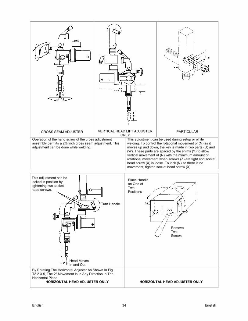
English English 34
CROSS SEAM ADJUSTER
VERTICAL HEAD LIFT ADJUSTER ONLY
PARTICULAR
Operation of the hand screw of the cross adjustment assembly permits a 2½ inch cross seam adjustment. This adjustment can be done while welding.
This adjustment can be used during setup or while welding. To control the rotational movement of (N) as it moves up and down, the key is made in two parts (U) and (W). These parts are spaced by the shims (Y) to allow vertical movement of (N) with the minimum amount of rotational movement when screws (Z) are tight and socket head screw (X) is loose. To lock (N) so there is no movement, tighten socket head screw (X)
By Rotating The Horizontal Adjuster As Shown In Fig. T3.2.3-5, The 2" Movement Is In Any Direction In The Horizontal Plane.
HORIZONTAL HEAD ADJUSTER ONLY
HORIZONTAL HEAD ADJUSTER ONLY
This adjustment can be locked in position by tightening two socket head screws.
Turn Handle
Head Moves In and Out
Place Handle on One of Two Positions
Remove Two Screws
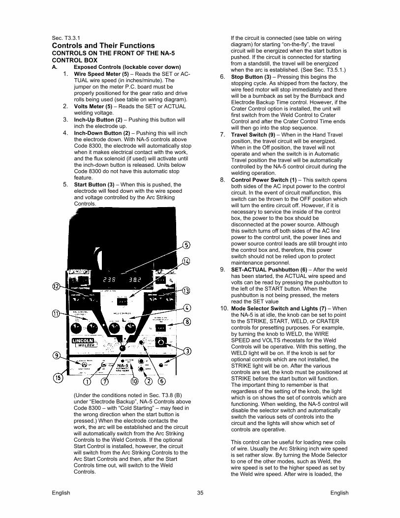
English English 35
Sec. T3.3.1
Controls and Their Functions CONTROLS ON THE FRONT OF THE NA-5 CONTROL BOX A. Exposed Controls (lockable cover down)
1. Wire Speed Meter (5) – Reads the SET or AC- TUAL wire speed (in inches/minute). The jumper on the meter P.C. board must be properly positioned for the gear ratio and drive rolls being used (see table on wiring diagram).
2. Volts Meter (5) – Reads the SET or ACTUAL welding voltage.
3. Inch-Up Button (2) – Pushing this button will inch the electrode up.
4. Inch-Down Button (2) – Pushing this will inch the electrode down. With NA-5 controls above Code 8300, the electrode will automatically stop when it makes electrical contact with the work, and the flux solenoid (if used) will activate until the inch-down button is released. Units below Code 8300 do not have this automatic stop feature.
5. Start Button (3) – When this is pushed, the electrode will feed down with the wire speed and voltage controlled by the Arc Striking Controls.
(Under the conditions noted in Sec. T3.8 (B) under “Electrode Backup”, NA-5 Controls above Code 8300 – with “Cold Starting” – may feed in the wrong direction when the start button is pressed.) When the electrode contacts the work, the arc will be established and the circuit will automatically switch from the Arc Striking Controls to the Weld Controls. If the optional Start Control is installed, however, the circuit will switch from the Arc Striking Controls to the Arc Start Controls and then, after the Start Controls time out, will switch to the Weld Controls.
If the circuit is connected (see table on wiring diagram) for starting “on-the-fly”, the travel circuit will be energized when the start button is pushed. If the circuit is connected for starting from a standstill, the travel will be energized when the arc is established. (See Sec. T3.5.1.)
6. Stop Button (3) – Pressing this begins the stopping cycle. As shipped from the factory, the wire feed motor will stop immediately and there will be a burnback as set by the Burnback and Electrode Backup Time control. However, if the Crater Control option is installed, the unit will first switch from the Weld Control to Crater Control and after the Crater Control Time ends will then go into the stop sequence.
7. Travel Switch (9) – When in the Hand Travel position, the travel circuit will be energized. When in the Off position, the travel will not operate and when the switch is in Automatic Travel position the travel will be automatically controlled by the NA-5 control circuit during the welding operation.
8. Control Power Switch (1) – This switch opens both sides of the AC input power to the control circuit. In the event of circuit malfunction, this switch can be thrown to the OFF position which will turn the entire circuit off. However, if it is necessary to service the inside of the control box, the power to the box should be disconnected at the power source. Although this switch turns off both sides of the AC line power to the control unit, the power lines and power source control leads are still brought into the control box and, therefore, this power switch should not be relied upon to protect maintenance personnel.
9. SET-ACTUAL Pushbutton (6) – After the weld has been started, the ACTUAL wire speed and volts can be read by pressing the pushbutton to the left of the START button. When the pushbutton is not being pressed, the meters read the SET value
10. Mode Selector Switch and Lights (7) – When the NA-5 is at idle, the knob can be set to point to the STRIKE, START, WELD, or CRATER controls for presetting purposes. For example, by turning the knob to WELD, the WIRE SPEED and VOLTS rheostats for the Weld Controls will be operative. With this setting, the WELD light will be on. If the knob is set for optional controls which are not installed, the STRIKE light will be on. After the various controls are set, the knob must be positioned at STRIKE before the start button will function. The important thing to remember is that regardless of the setting of the knob, the light which is on shows the set of controls which are functioning. When welding, the NA-5 control will disable the selector switch and automatically switch the various sets of controls into the circuit and the lights will show which set of controls are operative.
This control can be useful for loading new coils of wire. Usually the Arc Striking inch wire speed is set rather slow. By turning the Mode Selector to one of the other modes, such as Weld, the wire speed is set to the higher speed as set by the Weld wire speed. After wire is loaded, the
English English 36
Mode Switch is set back to Strike. 11. Electrode 'HOT' Light (10) – This light comes
on when the start button is pressed and the electrode circuit is electrically hot. It will stay on until the control signals the power source output to be off.
12. Circuit Breaker (15) – Protects the circuit from severe wire feed overloads or short circuit conditions.
B. Controls Under the Lockable Security Cover
1. Arc Striking Controls (11) – There are two controls in this mode. The Inch Wire Speed rheostat sets the wire speed during idle and after the NA-5 is energized by the Start circuit until welding current begins to flow. The Volts potentiometer controls the power source output voltage before the arc strikes. (The Volts potentiometer is not effective on R3S machines.) Proper setting of both of these controls is very important in order to have the best arc striking.
2. Weld Controls (4) – The Wire Speed and Volts potentiometers control the welding procedure.
3. Burnback and Electrode Back Up Time (8) – This control determines the length of time of burnback delay after the stop circuit is energized. Depending on the connections on the logic board, it may also determine the length of time the wire feed motor reverses after the stop button is pushed before it stops. The NA-5 as shipped from the factory is connected to stop the wire feed motor immediately with adjustable burnback delay when the stop button is pushed. The time delay control, therefore, should be adjusted to just the point where there is no sticking of the electrode in the crater at the end of the weld. If the circuit is connected so the wire reverses at the end of the weld, the distance the wire reverses after the welding arc goes out is controlled by the time setting and the Inch Wire Speed. The higher the Inch Wire Speed setting, the faster the wire reverses. If the wire does not back up far enough at the end of the weld, increase the time setting and/or turn the Inch Wire Speed to a higher setting. However, the inch speed should be set for best arc striking and the backup distance controlled by the time setting. If other modes of burnback and electrode backup are desired, refer to Sec. T3.5.2.
Burnback voltage and wire speed will be at the settings of the previous mode until the arc goes out.
4. Start Controls (12) (Optional) – On some
applications and procedures it is desirable to weld at a different wire speed and voltage at the start of a weld for a short period of time before swiching to the weld wire speed and volts. When the optional Start Controls are installed this can be done. The start wire speed and voltage can be higher or lower than the weld values and are completely independent of other control settings. Setting the start time to 0.00 seconds will bypass the start mode controls during the welding cycle.
Install the optional Start Controls per the nstructions included with the kit. Note that the same kit can be used for either Start Controls or Crater Controls and proper function depends on correct installation.
Although the timer can be set for 9.99 seconds, the majority of applications will require only 0.25 to 2.00 seconds. A good rule to follow for the Initial settings of the Start Controls is to set them at the same settings as the Weld Controls wire speed and voltage. The time delay can be set for about one second. After the first test weld, the controls can be re-adjusted as desired.
5. Weld Timer (14) (Optional) – With this option,
the weld duration is set by the Weld Time control. The control starts timing when the Weld Controls become operative and energizes the stop circuit when it reaches its set time. Install the optional Weld Timer module per the instructions included with the kit. Setting the weld time for zero seconds will bypass the weld mode control settings during the welding cycle.
6. Crater Controls (13) (Optional) – On some applications and procedures it is desirable to weld at a different wire speed and voltage at the finish of a weld for a short period of time for crater filling purposes. The optional Crater Controls has been designed for this purpose and allows higher or lower values than when welding. Setting the Crater time to 0.00 seconds will give zero crater-fill time; however, the crater settings will be active during Burnback time until the arc goes out.
Install the optional Crater Controls per the instructions included with the kit. Note that the same kit can be used for either Start Controls or Crater Controls and proper function depends on correct installation.
Although the timer can be set for 9.99 seconds, The majority of applications will require only 0.25 to 2.00 seconds. A good rule to follow for the initial settings of the Crater Controls is to set them at the same settings as the Weld Controls wire speed and voltage. The time delay can be set for about one second. After the first test weld, the controls can then be readjusted as desired.
February 1982
English English 37
Set-Up Instructions
WARNING ELECTRIC SHOCK CAN KILL: Have an electrician install and
service this equipment. Turn the input power off at the fuse
box before working on equipment. Do not touch electrically hot parts.
1. If using a multiprocess power source (SAM, SAF,
SA, DC-400, DC-600, DC-1000 or DC-1500 type), make connections and settings per the power source connection diagram for the process being used. See Sec.T2.3.4.
AUTO TAB When using the NA-5 with a DC-400 power source, the “Auto Tab” jumper on the NA5 voltage P.C. board must be connected in order for the inch down circuit to function. When the “Auto Tab” jumper is connected, the Cold Starting feature of the NA5 is disabled, and only the Hot Starting technique can be used. If the Cold Starting technique is to be used, the optional K826 Diode Kit must be installed on the DC-400.
2. Set the power source and NA-5 circuit polarity per information on Electrode Polarity in Sec. T2.3.
3. Depending upon the procedures and applications, decide: a) The means of arc striking and whether to start
the travel with the 'Start' button or the arc. b) Whether the initial bead size or penetration
requires use of the optional Start Controls. See Sec. T3.5 for descriptions of these various starting sequences and the rewiring needed to accomplish them.
4. Depending upon the procedures and applications:
a) Select the arc and travel stopping sequence. See Sec. T3.5.2 for a description of these various stopping sequences and the rewiring needed to accomplish them.
b) Decide if control of the ending bead size or crater filling requires use of optional Crater Controls. See Sec. T3.5.2.
5. Set the head position relative to the work as
required for the fixture, application, and procedures. See Sec. T3.2.3.
6. Rotate the wire straightener, if used, until the top of the straightener faces the wire reel. This is required for smooth feeding of the electrode into the straightener.
7. Refer to the instructions for the wire contact assembly being used. See Sec. T2.2.6, T2.2.7, T2.5.3 or T2.5.4.
8. The mount for standard 50 and 60 pound electrode coils includes a two-position brake assembly. Generally the brake should be at the inner position (nearest to the wire reel shaft) for wire feed speeds below 400"/ min. It should be at the outer position for faster wire speeds. To adjust the brake position, remove the wire reel. Pull the cotter pin that holds the brake shoe to the arm, move the shoe, and replace the cotter pin. Do not bend the cotter pin – it is held in place by a friction fit.
9. Load the wire reel per Section T3.2.2 or install the Speed-Feed drum or reel per Section T2.5.7-A or -B.
10. Straighten the first six inches of electrode and push it through the wire straightener to the drive rolls. To use the cored wire straightener, remove the knurled nut at the top, feed the wire through the nut, down into the straightener, and into the drive rolls. Screw the nut back onto the straightener. Feed wire through the nozzle tip and adjust the straightener for optimum straightness. With wire contact assemblies, except the K231, adjust until the electrode is straight as it comes out of the nozzle. Do not completely straighten the wire when using a K231 contact nozzle because the nozzle relies on a small curvature of the electrode for proper electrical contact within the contact tip.
11. Set the travel speed as specified by the procedures. With the wire feeder travel switch set to 'Hand Travel', the travel runs without welding permitting accurate measurement of travel speed. When using a Lincoln travel carriage, adjust the speed with the rheostat and the direction with the toggle switch on the carriage control panel.
12. Connect the work lead to the work or a suitable piece of scrap. Clip the end of the electrode to a sharp point.
13. Preset the Start (if used), Weld, and Crater (if used) Controls to the wire speed and voltage specified in the procedure.
14. Make several test welds, readjusting the controls in the following order: a) Set the Arc Striking, Inch Wire Speed, and
Volts Controls for optimum arc striking. The optimum strike control settings for most processes will be typically 4 - 5 volts higher than the Weld Mode Voltage Setting and 40 - 50% of the Weld Mode Wire Feed Speed Setting (possibly lower if cold starting is used).
b) If striking is still not satisfactory, refer to Sec. T3.5.2 for information on wire feed motor acceleration.
c) If installed, adjust the “Start Controls” to set the welding procedures for the time set on the timer to provide the bead size, penetration, or other factor as needed for the application (refer to Sec.T3.5.1).
d) If installed, adjust the “Crater Controls” to set the welding procedures for the set time after the stop button is pressed to provide the bead size or fill the crater as needed for the application (refer to Sec. T3.2.2).
e) Set the “Burnback Time” to provide the stopping characteristics needed.
April 1988
English English 38
Sec. T3.5.1
Starting and Stopping Sequences Means of Arc Striking A. All NA-5 codes utilize “hot start” arc striking
which operates as follows: 1. With the electrode not touching the work, press
the 'Start' button. 2. The electrically “hot” electrode inches down as
set by the 'Inch Wire Speed' control. 3. When it makes electrical contact with the work,
the arc strikes and the circuit automatically switches from 'Strike' settings to 'Weld' (or Start, if used) settings.
B. NA-5 models above Code 8300 offer both “hot
start” arc striking, as described above, or “cold start” arc striking which operates as follows: 1. Press the Inch Down button until the tip of the
electrode touches the work, automatically stops, and the flux (if used) is automatically dispensed. NOTE: If Inch Speed is set too high, the electrode may stop with too much force on its tip resulting in possibly poor starting.
2. The arc establishes when the 'Start' button is pressed and the circuit automatically switches to Weld (or start, if used) settings. Should the arc not start immediately, the wire will retract slightly until the arc is established and then feed down in the normal manner.
Use either the standard “on-the-fly” travel starting or rewire the controls for “standstill” travel starting per Sec. T3.5.2 below.
C. Optional 'Start Controls'
1. Recommended for applications where penetration, bead size, and other weld characteristics must be carefully controlled at the start.
2. The starting sequence is as described above except, when the arc strikes, the machine welds at the wire speed and voltage set by the 'Start Controls' panel until the time set on the thumbwheel switch elapses. The circuit then automatically switches to 'Weld Controls' wire speed and voltage. Actual settings depend upon the application requirements.
3. Setting the start time to 0.00 seconds will bypass the Start Mode controls durng the weld cycle.
D. Available options for applications with
particularly difficult starting 1. K238 High Frequency Generator - See Sec.
T2.5.8. 2. K237 Linc-Fill Starting Relay - See Sec.
T2.5.12.
Sec. T3.5.2
Setting Travel Starting and Stopping Standard machines can be connected for a variety of starting and stopping sequences. STARTING SEQUENCES A. “On-the-Fly” Travel Starting
When shipped, all models are connected for “On-the-Fly” travel starting. The sequence follows:
1. With the electrode NOT touching the work, press the 'Start' button. This starts both the wire feed and travel motors.
2. When the electrically “hot” electrode touches the work to start the arc, there is relative motion between the end of the electrode and the work. This “scratching” type contact helps assure consistent arc striking.
This sequence is recommended for most welding, including: 1. Roundabouts and any other weld which ends at
its starting point. A K337 Weld Timer Module to control the welding cycle duration can be installed.
2. Welds started on a run-out tab. 3. For improved arc striking on any application.
B. “Standstill” Travel Starting
All models can be reconnected so the travel remains at a standstill until the arc starts. “Standstill” travel starting is used when the electrode must be started at a precise location. For consistent arc striking with “Standstill” travel starting, always clip the end of the electrode to a sharp point before starting.
C. Stopping Sequences
As shipped, the travel stops when the 'Stop' button is pressed producing a smaller crater area. When the end overlaps the beginning of the weld, reconnecting to stop the travel later in the sequence spreads the crater over a longer area.
D. Reconnecting the Travel Starting and/or
Stopping Sequence: to change the travel sequence, turn off all input power to the NA-5 control box. Open the control box. The logic board is mounted on the back of the box in the upper right hand corner. To change the travel circuit for the various modes of starting and stopping, follow the information on the table of the wiring diagram for the NA-5 being used. Table T.3.5 at the end of this seciton also shows information on reconfiguring the travel sequences.
E. Wire Feed Motor Acceleration The NA-5 has two
different speeds of controlled wire feed motor acceleration. As shipped, the unit is connected for fast acceleration which is best for most applications. To change to the slower acceleration, turn off all input power to the NA-5 control box. Open the control box. Locate the 'Control' P.C. Board mounted on the back of the box in the lower right hand corner and change the jumper plug from the 'F' pin to the 'S' pin.

English English 39
F. Burnback and Electrode Back-Up
The primary consideration in setting the arc stopping sequence is to prevent the electrode from sticking in the puddle. This is easily done with the machine as shipped. The standard sequence when the optional 'Crater Controls' are not used follows:
1. Press the 'Stop' button. 2. The wire feed motor stops and the Burnback
time delay starts. 3. The arc continues to burn the electrode back
from the puddle until the arc goes out or the time set on the thumbwheel switch elapses. This control should be set for just enough burnback time to prevent crater sticking.
There are two other ways this circuit can be connected. One will cause the wire to retract* with a contactor drop out delay at the end of the weld, and the second will cause the wire to retract* during burnback time and there will be no contactor drop out delay at the end of the weld. If either one of these alternate methods of stopping the weld is desired, the connections on the logic board can be easily changed. To change the stopping sequence, turn the input AC power off at the power source, remove the screw holding the inner panel and swing the panel open. Change the connections (older models) or switch positions (newer models) on the logic board as follows: WHEN THE “STOP” BUTTON IS PRESSED: 1. Feed motor stops and electrode burns back
with contactor delay (standard)
For older models For newer modelsǂ lead 693 to pin 3 lead 690 to pin 4
Switch #2
2. Feed motor inches up and electrode burns back
with contactor delay For older models For newer modelsǂ lead 693 to pin 1 lead 690 to pin 4
Switch #2
3. Feed motor inches up and contactor opens (no burnback)
For older models For newer modelsǂ lead 693 to pin 1 lead 690 to pin 2
Switch #2 G. Optional 'Crater Controls'
Recommended for applications where the ending bead size must be controlled, the crater must be filled, including roundabouts, and other welds where the end overlaps the start. When the 'Stop' button is pressed, the machine welds at the wire speed and voltage set by the 'Crater Controls' until the time set on the thumbwheel switch elapses. The circuit then automatically switches to the arc stopping sequence described above. NOTE: Setting crater time to 0.00 seconds will give zero crater fill time; however, the crater settings will be active during burnback time until the arc goes out. *Wire will retract at Weld Mode Speed (or Crater Mode Speed, if installed) until the arc goes out, then retract at Strike Mode Speed for remainder of burnback time.
February 1996
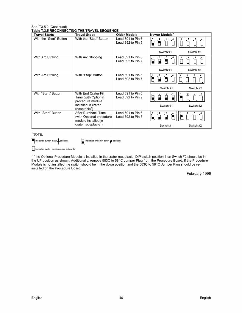
English English 40
Sec. T3.5.2 (Continued) Table T.3.5 RECONNECTING THE TRAVEL SEQUENCE
Travel Starts Travel Stops Older Models Newer Models1 With the “Start” Button With the “Stop” Button Lead 691 to Pin 6
Lead 692 to Pin 5
With Arc Striking With Arc Stopping Lead 691 to Pin 6 Lead 692 to Pin 7
With Arc Striking With “Stop” Button Lead 691 to Pin 5 Lead 692 to Pin 7
With “Start” Button With End Crater Fill Time (with Optional procedure module installed in crater receptacle1)
Lead 691 to Pin 6 Lead 692 to Pin 9
With “Start” Button After Burnback Time (with Optional procedure module installed in crater receptacle1)
Lead 691 to Pin 6 Lead 692 to Pin 8
1NOTE:
Indicates switch in up position Indicates switch in down position
Indicates switch position does not matter
1If the Optional Procedure Module is installed in the crater receptacle, DIP switch position 1 on Switch #2 should be in the UP position as shown. Additionally, remove 583C to 584C Jumper Plug from the Procedure Board. If the Procedure Module is not installed the switch should be in the down position and the 583C to 584C Jumper Plug should be re-installed on the Procedure Board.
February 1996
Switch #1 Switch #2
Switch #1 Switch #2
Switch #1 Switch #2
Switch #1 Switch #2
Switch #1 Switch #2
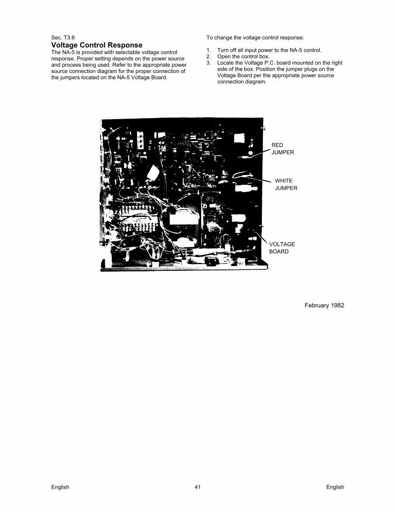
English English 41
Sec. T3.6
Voltage Control Response The NA-5 is provided with selectable voltage control response. Proper setting depends on the power source and process being used. Refer to the appropriate power source connection diagram for the proper connection of the jumpers located on the NA-5 Voltage Board.
To change the voltage control response: 1. Turn off all input power to the NA-5 control. 2. Open the control box. 3. Locate the Voltage P.C. board mounted on the right
side of the box. Position the jumper plugs on the Voltage Board per the appropriate power source connection diagram.
February 1982
RED JUMPER
WHITE JUMPER
VOLTAGE BOARD
Sec. T3.7
Automatic Shutdown If the NA-5 voltage control is unable to supply the 'SET' value of arc voltage while welding, the automatic shutdown circuit will activate. This protection circuit immediately returns the NA-5 control to idle state within a few seconds after the arc voltage discrepancy occurs. Typical causes for the activation of this protective shutdown circuit are as follows: 1. 'SET' value of arc voltage is outside the power source
range. 2. Power source voltage control not set for 'REMOTE'. 3. Misconnection of NA-5 control cable leads to power
source. 4. Incorrect weld polarity connections, or settings, at NA-5
or power source. 5. Lost connection of NA-5 voltage sensing leads (#67 and
#21) between arc and voltage control, or a blown 1/8 amp fuse on voltage P.C. boards built since 1983.
With NA-5 units above Code 8300, the conditions of (4) and (5) above would result in the wrong wire feed direction when the weld is started. (See Sec. T3.8.) In the case of full range control power sources, such as the DC-600, this protective shutdown circuit could prevent welding under the conditions of (3), (4) and (5) above by holding the power source output at minimum, possibly providing too low of a power source output to even establish an arc, or causing the field fuse to blow because of rapid field reversals with NA-5 controls above Code 8300. (See Sec. T3.8.) Although out of range shutdown can occur with all power sources when working with very low or very high arc voltages, it is most likely to occur when using the R3S models with the somewhat limited voltage range of the various taps. For instance, if the R3S-400 triangle tap setting is for 31 volts, the range of control from the remote circuit is approximately 7 volts, i.e., 27½ to 34½ volts at nominal input voltage. If the NA-5 controls are set for 29 volts and the input voltage to the R3S goes up, it may not be possible for the NA-5 control circuit to hold the 29 volts so the welding will shut down. By changing to the 27 volt triangle setting, the range will be approximately 23½ to 30½ volts and at high input voltage there will be sufficient control to hold the SET arc voltage. On these machines, if the NA-5 stops welding, follow this procedure: A. Move the NA-5 voltage set point 2 volts lower than the
desired procedure and make a test weld. 1. If the NA-5 still shuts down, go to Step (B) below. 2. If the NA-5 keeps welding, change the R3S triangle
setting to the next higher voltage and reset the NA-5 set point to the desired procedure. The R3S is now set properly unless there is a significant change in input voltage. Skip the following step.
B. Move the NA-5 voltage set point 2 volts higher than the
desired procedure and make a test weld. 1. If the NA-5 now keeps welding, change the R3S
triangle setting to the next lower voltage and reset the NA-5 set point to the desired procedure. The R3S is now set properly unless there is a significant change in input voltage.
2. If the NA-5 still shuts down, refer to the following paragraph and the other possible causes previously listed.
In some cases, it is also possible to hold the 'ACTUAL' button pressed while starting the arc. Before the NA-5 shuts down, the actual arc voltage can be read on the digital meter. Comparing this reading to the 'SET' reading will tell what change in the range controls of the power source are required so it can supply the desired voltage. Should the meter read zero, check the NA-5 sensing leads (#21 and #67) connections. Should the meter read a minus (–) voltage, the polarity connections or settings at the NA-5 or power source are wrong. This same general procedure can be used on other power sources. For example, if the NA-5 keeps shutting down and the other possible causes have been checked, adjust the SET voltage higher and/or lower than the desired voltage. If the NA-5 continues to weld at one of these voltages, it can then be determined what change in the range controls of the power source are required so it can supply the desired voltage.
July 1983

English English 43
Sec. T3.8
Cold Start Circuitry NA-5 controls above Code 8300 contain circuitry added to the Voltage P.C. board to facilitate the “cold starting” features of these units.* This circuitry senses the voltage present between the electrode and work, via leads #67 and #21, and permits normal wire feed if this voltage exceeds typically about 6.5 volts DC. However, if this voltage level is not exceeded, or drops below typically about 3.5 volts DC, the Auto Stop activates while inching down or electrode backup occurs if the arc start circuit has been initiated. *Units below Code 8300 can be provided with the cold start circuitry by replacing the old code L-6257 Voltage board with the new G-1556 Voltage board. This new board will mount and connect in the same manner as the old board, except the third harness connector (previously connected to a jumper plug) must be connected to the lower receptacle of the new Voltage board. NOTE: HI-FREQ starting cannot be used with converted units below Code 8300. A. Auto Stop
When the inch down button is pressed, a low level DC voltage signal is applied between the electrode and work which permits the wire to inch down normally. When the electrode makes electrical contact with the work, it shorts out this signal causing the wire feed to automatically stop and the flux solenoid to activate until the inch down button is released. Inch up will not be affected by this circuit. This voltage signal is supplied by the 24 volt transformer on the NA-5 Voltage P.C. board only when the inch down button is pressed. The level of the signal appearing between the electrode and work will be dependent on the impedance present across these points, including the power source output stud impedance. If this impedance is less than 500 ohms the applied signal level may be too low to permit the electrode to inch down.
B. Electrode Backup
If while starting or welding the electrode stubs or shorts to work, the resulting loss of arc voltage will cause the electrode to momentarily back up until the arc voltage is re-established, then change back to normal feed direction. NOTE: The “cold starting” circuitry will cause the NA-5 to feed in the wrong direction when the start button is pressed if the 'ACTUAL' arc voltage, as read on the NA-5 voltmeter, does not exceed typically about 6.5 volts. Usual causes for this situation are:
1. No wire loaded through the NA-5 head and
nozzle assembly (except when using the K148 nozzle).
2. No power source weld cable connection to the NA-5 head or work.
3. Incorrect electrode polarity connections at the NA-5 or power source.
4. Little or no output voltage from the power source.
5. An open #67 or #21 voltage sensing lead to the NA-5 control box, or a blown 1/8 amp fuse on
voltage P.C. boards built since 1983. July 1983

English English 44
Sec. T3.9
Security of Weld Procedure Settings There are two means provided to prevent or limit unauthorized readjustment of the NA-5 voltage and wire feed speed controls once set to the desired procedure. 1. The security panel of the NA-5 can be locked to
prevent access to the control knobs. 2. The control range of the procedure control knobs
can be limited to either about 3% or about 15% of the full range control by installing a knob rotation stop screw to any or all of the control knobs. This stop screw is installed in the following manner: a) Turn off the input power to the NA-5. b) Loosen each knob set screw and remove all
knobs, including the rotary selector switch knob.
c) Remove the felt seal and square spacer tube mounted behind each control knob.
d) Open the control box and disconnect, then remove, the procedure control P.C. board assembly and its panel insulation.
e) Install a ½" long, pan or round head, #4 sheet metal screw into the .10" dia. hole, located beneath each square hole, so the head is on the back side of the panel (inside the control box).
f) Remount the P.C. board assembly and its panel insulation, then reconnect the P.C. board and close and secure the control box.
g) Remount the rotary selector switch knob, and replace each square spacer tube and felt seal so the #4 screw protrudes between the tube and the felt seal.
h) Turn on the NA-5 input power and set the desired procedure by rotating the shafts of the controls.
i) Carefully replace each control knob so the #4 screw inserts into the center of the shorter length channel on the back of the knob for about 3% of the total range of control or into the center of the longer length channel for about 15% of the total range of control.
j) With finger pressure on the knob against the felt seal, carefully retighten the set screw of each knob.
NOTE: Steps (h) thru (j) will have to be repeated if it is desired to change the procedure settings to values outside the selected 3% or 15% control range limit.
February 1982

English English 45
Maintenance Sec. T6.2
Mechanical Maintenance WARNING
ELECTRIC SHOCK CAN KILL: Have an electrician install and
service this equipment. Turn the input power off at the fuse
box before working on equipment. Do not touch electrically hot parts.
Sec. T6.2.1
Wire Drive Gearbox Once a year recoat all gears with a non-fluid type lubricant (Lincoln Spec. E2322). For access to the gears in one chamber, remove the adapter plate and motor assembly. To lubricate the gears in the other chamber, remove one of the pipe plugs and feed grease in contact with the bevel gear teeth while rotating the output shaft until all teeth are lubricated.
February 1982 Sec.T6.2.2
Changing Wire Size and Wire Feed Gear Ratios
Gear Ratio
Feed Speed Range
(in/mm)
Max. Wire Size
Cored Wire Solid Wire
21:1 100 – 2070 .052 .052 57:1 38 – 762 3/32 1/16 95:1 22 – 428 5/32 1/8
142:1 15 – 289 5/32 7/32 Four wire size conversion kits are available to convert wire feeder for different size or type electrodes. The kits include drive rolls and guide tubes for the wire specified:
3/32 – 7/32 Solid or Cored T13724-A 1/16 – 3/32 Solid or Cored T13724-B
.035 – .052 Solid T13724-C .045 – .052 Cored T13724-D
To have proper wire speed calibration, the proper combinations must be used. See section F.5, or NA-5 wiring diagram for proper pin settings on the wire speed meter PC board. Four gear ratios are available — 21:1, 57:1, 95:1 and 142:1. To change the gear ratio, replace the motor pinion and the first reduction gear per the following instructions: (Refer to P-100-C and P-135-C.) 1. Remove the four round head screws which mount
the motor adapter plate to the gearbox. Remove the motor and adapter plate from the gearbox.
2. Take the two longer screws removed in Step (a) and screw one into each of the tapped holes located in the face of the fiber input gear (Item 13). Insert the screws through the full thickness of the gear and, using a screwdriver wedged between the screws to prevent rotation, remove the hex nut (Item 10) which holds the gear to the shaft. Remove the flat washer (Item 11).
3. Pull the gear from the shaft using the screws as a pulling device.
4. Be certain the woodruff key (Item 5) is properly located on the shaft. Turn the adapter plate mounting screws into the new fiber gear from the stenciled side and place the gear on the shaft. Replace the flat washer, tighten the hex nut, and remove the adapter plate mounting screws from the gear.
5. After noting the relation of the adapter plate with the motor leads, remove the adapter plate from the motor. Support the pinion properly and, with the proper size punch, drive the roll pin which holds the pinion out of the shaft. Pull the pinion off. Install the new pinion and replace the roll pin. Replace the adapter plate in its original location.
6. Cover the teeth of the motor pinion and the input gear with a non-fluid type lubricant (Lincoln Spec. E2322). This can be scooped from the cavity of the gear case.
7. Reassemble the motor on the gearbox being certain the gears mesh properly and the adapter plate locating bead is in its cavity. Replace and tighten the four screws and the lockwashers removed in Step (1).
8. Jumper on wire speed meter P.C. board must be properly positioned for the gear ratio and drive rolls being used. (See table on wiring diagram.)
July 1983 Sec. T6.2.3
Wire Drive Mechanism Drive mechanisms for three wire size ranges are available - .035 thru .052", 1/16 thru 3/32" and 3/32 thru 7/32". If changing to wire sizes outside the range, change the drive rolls and the incoming and outgoing guide tubes. Also change the gear ratio (Sec. T6.2.2) if necessary. The electrode is driven by gripping between the grooved drive rolls and a spring loaded idle roll. Replace the drive rolls when they become worn. The drive rolls for .045 – .052 cored electrode 1/16" and larger diameter electrodes have two sets of teeth so they can be reversed once before they must be replaced.
February 1982 Sec. T6.2.4
Wire Straighteners 1. For Solid Electrode
Periodically inspect the slide bushing at the top of the straightener and the ingoing wire guide at the bottom of the straightener for signs of wire milling. If necessary, rotate the guide to present an unworn surface. To reverse the slide bushing for a fresh wear surface, remove the cross adjustment screw and turn the bushing over.
2. For Flux Cored Electrode Severe wear to the “V” groove in the curved arm of the straightener can result in wire wander at the arc. Periodically check the groove and replace the arm when badly worn. Also replace the ingoing guide at the top of the straightener if it shows signs of milling the wire.
February 1982
English English 46
Sec. T6.3
Electrical Maintenance Sec. T6.3.1
Control Box Every three months inspect the control box. If needed, blow dirt out using low pressure air. No other maintenance should be required.
February 1982 Sec. T6.3.2
Circuit Protection The circuit breaker mounted at the bottom left hand corner of the control box protects the control circuit from short circuit conditions and from severe wire feed overloads. If it opens, determine and correct the cause of the overload. To reset the circuit breaker, push the button. If a complete or partial short occurs in the field circuit or if there is a defect on the Power P.C. board, a 1/2 amp slow-blow type fuse will blow on early model machines, or a PTC Resettable Fuse will open on later model machines. This field circuit protection is mounted on the Power P.C. board inside the control box. Before replacing the fuse or allowing the PTC Resettable Fuse to reset and restoring power to the machine, check the motor field for a shorted condition. Normal field resistance is approximately 700 ohms. With NA-5 controls above Code 8300, the field circuit protection may also open due to frequent motor field reversals from application problems affecting the “cold” starting circuit, such as the power source output being too low to establish an arc, or the welding procedure causing frequent electrode-to-puddle shorting. (Refer to Sec. T3.7.) The power supply for the electronic circuitry is protected by a 1/2 ampere slow-blow type fuse. It is located on the Power P.C. board inside the control box. The 1/8 amp fast-blow fuse, on the Voltage P.C. boards built since 1983, protects the NA-5 circuitry from damage which may result from a ground, or case, faulted control lead. If this fuse blows, the NA-5 arc voltage sensing lead circuit will be opened (see Section T3.7), and the NA-5 Troubleshooting Guide should be consulted to detect and clear the fault.
September 1998 Sec. T6.3.3
Ground Fault Fuse Protection A 1/8 amp fast-blow fuse is located on the NA-5 Voltage board. This fuse will protect the NA-5 circuitry from damage resulting from a ground, or case faulted control lead when arc voltage potential exists between ground and the NA-5 circuit common (#510). Such a condition typically exists when the NA-5 polarity connections are set for electrode negative.
April 1988
Customer Assistance Policy The business of The Lincoln Electric Company is manufacturing and selling high quality welding equipment, consumables, and cutting equipment. Our challenge is to meet the needs of our customers and to exceed their expectations. On occasion, purchasers may ask Lincoln Electric for advice or information about their use of our products. We respond to our customers based on the best information in our possession at that time. Lincoln Electric is not in a position to warrant or guarantee such advice, and assumes no liability, with respect to such information or advice. We expressly disclaim any warranty of any kind, including any warranty of fitness for any customer’s particular purpose, with respect to such information or advice. As a matter of practical consideration, we also cannot assume any respon- sibility for updating or correcting any such information or advice once it has been given, nor does the provision of information or advice create, expand or alter any warranty with respect to the sale of our products Lincoln Electric is a responsive manufacturer, but the selection and use of specific products sold by Lincoln Electric is solely within the control of, and remains the sole responsibility of the customer. Many variables beyond the control of Lincoln Electric affect the results obtained in applying these types of fabrication methods and service requirements. Subject to Change – This information is accurate to the best of our knowledge at the time of printing. Please refer to www.lincolnelectric.com for any updated information.

English English 47
WEEE 07/06
En
glis
h
Do not dispose of electrical equipment together with normal waste! In observance of European Directive 2012/19/EC on Waste Electrical and Electronic Equipment (WEEE) and its implementation in accordance with national law, electrical equipment that has reached the end of its life must be collected separately and returned to an environmentally compatible recycling facility. As the owner of the equipment, you should get information on approved collection systems from our local representative. By applying this European Directive you will protect the environment and human health!
Spare Parts 12/05
For Spare Parts references visit the Web page: https://www.lincolnelectric.com/LEExtranet/EPC/
Authorized Service Shops Location 09/16
The purchaser must contact a Lincoln Authorized Service Facility (LASF) about any defect claimed under Lincoln's warranty period.
Contact your local Lincoln Sales Representative for assistance in locating a LASF or go to www.lincolnelectric.com/en-gb/Support/Locator.