· sinclair ant typ freq range ant series config-enviro rating freq split pattern pim rating conn...
TRANSCRIPT


Sinc
lair
Ant
Ty
pFr
eq
Ran
geA
nt
Serie
sC
onfig
-En
viro
R
atin
gFr
eq
Split
Patte
rnPI
M
Rat
ing
Con
n(
Elec
El
evTu
ne
Freq
Mou
nt-
Gai
n-
Mis
c.
Opt
ions
Stur
ctFi
nish
-Sp
ec
Ass
embl
y)
Prot
o
Envi
ronm
enta
l Rat
ing
PIM
Rat
ing
Elec
tric
al E
leva
tion
X=P
roto
type
S=Si
ncla
irS
=Sta
ndar
d du
tyL=
Enh
ance
d P
IM ra
ting
Dnn
=Ele
ctric
al d
ownt
ilt in
Mis
cella
neuo
s O
ptio
nsH
=Hea
vy d
uty
S=S
tand
ard
PIM
ratin
gde
gree
s w
here
nn
= (0
0 - 1
0)B
C=
Bird
cap
Ant
enna
Typ
eU
=Ultr
a du
tyU
nn=E
lect
rical
upt
ilt in
Cx=
Whe
re x
= (0
- 99
) des
igna
ting
cabl
e le
ngth
C=C
ollin
ear o
mni
degr
ees
whe
re n
n =
(00
- 10)
(in fe
et) i
f oth
er th
an s
tand
ard.
Thi
s co
de m
ust n
otD
= E
xpos
ed d
ipol
eC
onfig
urat
ion
been
use
d fo
r ord
erin
g ju
mpe
r cab
les.
E=E
nclo
sed
dipo
le2=
Dua
l bay
. Sin
gle
inpu
t cab
leC
onne
ctor
Gai
nC
G=
Coa
st g
uard
G=G
roun
d pl
ane
4=Fo
ur b
ay. S
ingl
e in
put c
able
BF=
BN
C fe
mal
eG
3 =
3 dB
HP
= H
igh-
pow
er v
ersi
on (s
peci
al a
ssem
bly:
sho
uld
I=In
-bui
ldin
gD
=Dua
l arr
ay. T
wo
sepa
rate
inpu
t cab
les
BM
=BN
C fe
mal
eG
5 =
5 dB
be a
ssig
ned
an E
-num
ber i
nste
ad?)
M=M
obile
L=Lo
w p
rofil
eD
F=7/
16 D
IN fe
mal
eG
6 =
6 dB
IC=
Inte
grat
ed ic
e-gu
ard
vers
ion
(spe
cial
ass
embl
y:P
=Sin
gle
pola
rity
pane
lM
=Mar
ine
vers
ion
(gen
. 156
-162
.5 M
Hz)
DM
=7/1
6 D
IN m
ale
G8
= 8
dBsh
ould
be
assi
gned
an
E-n
umbe
r ins
tead
?)R
=Rad
ome-
encl
, yag
i/l.p
./etc
.Q
=Qua
d ar
ray.
Fou
r sep
arat
e in
put c
able
sN
F=N
fem
ale
LM=
Less
mas
tT=
Tran
spor
t, lo
w p
rofil
e (e
xcal
)R
=Rad
ome
NM
=N m
ale
LS=
Inte
grat
ed li
ghte
ning
spi
ke v
ersi
onV
=Cor
ner o
r circ
ular
refle
ctor
T=Tr
iple
arr
ay. T
hree
sep
arat
e in
put c
able
sS
F=S
MA
fem
ale
Stru
ctur
eLV
= Lo
w-V
SW
R v
ersi
on (N
ote:
spe
cial
ass
embl
y:X
=Dua
l pol
arity
"sla
nt 4
5" p
anel
X=
Cro
ss P
olar
ized
(Pan
nel A
nten
na)
SM
=SM
A m
ale
shou
ld b
e as
sign
ed a
n E
-num
ber i
nste
ad?)
Y=Y
agi
C=
Circ
ular
ly P
olar
ized
(Pan
nel A
nten
na)
TF=T
NC
fem
ale
W =
Wel
ded
SS
C=
Sta
nele
ss S
teel
Cla
mps
V=
Ver
tical
ly P
olar
ized
(Pan
nel A
nten
na)
TM=T
NC
mal
eU
F=U
HF
fem
ale
Freq
. Ran
ge (M
Hz)
UM
=UH
F m
ale
Fini
shin
g O
ptio
ns1=
0 - 1
00A
BK
= C
olor
fini
sh –
bla
ck a
nodi
zing
2=10
0 - 2
99A
BU
= C
olor
fini
sh -
blue
ano
dizi
ng3=
300
- 599
Freq
uenc
y Sp
litA
GO
= C
olor
fini
sh -
gold
ano
dizi
ng4=
600
- 999
FX=N
o fre
quen
cy s
plits
exi
st o
r ant
icip
ated
Patte
rn o
r Wav
elen
gth
CC
C=
Chr
omat
e C
onve
rsio
n C
oatin
g5=
1000
- 20
00Fn
=Whe
re n
=(1-
99) d
esig
natin
g th
e fre
q. s
plit
code
nn=A
zim
uth
beam
wid
th in
deg
rees
whe
re n
n=(3
0-99
).C
GO
= C
olor
fini
sh -
gold
chr
omat
e6=
2400
- 25
00T1
=Tet
ra b
and
1. C
over
s at
leas
t 380
-400
MH
zP
anel
s an
d ot
her s
ecto
red
ant's
onl
y.E
BK
= C
olor
fini
sh –
bla
ck e
poxy
pai
nt8=
4900
- 50
00T2
=Tet
ra b
and
2. C
over
s at
leas
t 410
-430
MH
zP
2=1/
2 W
(fix
ed-p
atte
rn e
xpos
ed d
ipol
es a
nd w
hips
onl
yE
BU
= C
olor
fini
sh –
blu
e ep
oxy
pain
tTB
=Cov
ers
both
Tet
ra b
ands
, 380
-430
MH
zP
3=3/
8 W
(fix
ed-p
atte
rn e
xpos
ed d
ipol
es o
nly
EW
H=
Col
or fi
nish
– w
hite
epo
xy p
aint
P4=
1/4
W (f
ixed
-pat
tern
exp
osed
dip
oles
onl
yE
GR
= C
olor
fini
sh –
gra
y ep
oxy
pain
tA
nten
na S
erie
sP
5=5/
8 W
(mob
ile w
hip
ante
nnas
onl
y)M
AB
K=
Col
or fi
nish
- Mili
tary
type
III b
lack
ano
dizi
ng01
=gro
und
plan
e (1
01, 2
01, 3
01, 4
01)
28=c
orne
r ref
lect
or (2
28)
PA
=Fie
ld a
djus
tabl
e pa
ttern
, or b
eam
wid
thP
BK
= C
olor
fini
sh –
bla
ck p
olyu
reth
ane
pain
t02
=cor
ner r
efle
ctor
(302
, 402
)29
=coi
l col
linea
r om
ni (2
29, 3
29)
PC
=Circ
ular
pol
ariz
edP
BU
= C
olor
fini
sh –
blu
e po
lyur
etha
ne p
aint
03=3
ele
men
t yag
i (20
3, 3
03)
30=t
etra
pan
el (3
30)
PS
=Cro
ss p
olar
ized
, or S
lant
PW
H=
Col
or fi
nish
– w
hite
pol
yure
than
e pa
int
06=6
ele
men
t yag
i (20
6, 4
06)
32=2
pha
sor e
lem
ent,
3 dB
d ga
inP
GR
= C
olor
fini
sh –
gra
y po
lyur
etha
ne p
aint
07=7
ele
men
t yag
i (30
7)33
=pha
sor c
ollin
ear o
mni
(233
)P
SB
= C
olor
fini
sh –
sha
dow
bro
nze
pain
t10
=1-b
ay e
xpos
ed d
ipol
e (2
10, 3
10)
35=2
-bay
exp
osed
dip
ole
(235
, 335
)TB
K=
Col
or fi
nish
- bl
ack
teflo
n11
=2-b
ay e
nclo
sed
dipo
le (4
11)
38=o
mni
(238
)Tu
ne F
requ
ency
TWH
= C
olor
fini
sh –
whi
te te
flon
12=2
-bay
exp
osed
dip
ole
(212
, 312
)40
=dat
a an
tenn
a (4
40)
F0=U
ntun
ed. T
o be
tune
d by
the
Cus
tom
er.
TBU
= C
olor
fini
sh –
blu
e te
flon
14=4
-bay
exp
osed
dip
ole
(214
, 314
)41
=dat
a an
tenn
a (4
41)
Ff=W
here
f =
(030
0 - 9
995)
, des
igna
ting
the
cent
re fr
eque
ncy
TGR
= C
olor
fini
sh –
gra
y te
flon
14=4
-bay
enc
lose
d di
pole
(414
)50
=yag
i (25
0, 3
50)
(1/2
MH
z in
crem
ents
) in
MH
z w
ith 1
dec
imal
poi
nt. E
xam
ple:
CW
H=
Rad
ome
mat
eria
l col
or –
whi
te15
=yag
i (41
5)60
=rad
afle
ctor
(260
, 360
, 460
)Fo
r a S
C22
9 an
tenn
a or
dere
d w
ith c
entre
freq
uenc
y of
138
.5C
GR
= R
adom
e m
ater
ial c
olor
– g
ray
17=l
ow-g
ain
omni
-dire
ctio
nal (
217)
69=c
ollin
ear o
mni
(369
)M
Hz,
the
"Ff"
desi
gnat
or w
ill b
e: F
1385
18=8
-bay
exp
osed
dip
ole
(218
, 318
)70
=cel
lula
r/pan
el (4
70)
Spec
ial A
ssem
bly
Iden
tifie
r19
=9-b
ay e
nclo
sed
dipo
le (4
19)
72=c
ivil
avia
tion
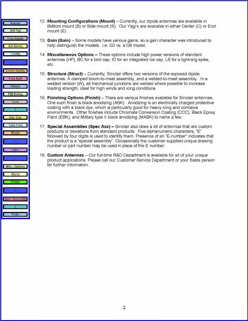
Mou
ntin
g C
onfig
urat
ion
Five
alp
hanu
mer
ic c
hara
cter
s, "E
" fol
low
ed b
y20
=col
linea
r om
ni (3
20, 4
20)
79=
9 dB
d ga
in, 7
pha
sor c
ollin
ear o
mni
B=B
otto
m m
ount
(a.k
.a. T
op M
ount
).fo
ur d
igits
. Pre
senc
e of
an
"E-n
umbe
r" in
dica
tes
21=e
xcal
iber
mob
iles
(221
, 321
)80
=pha
sor c
ollin
ear o
mni
(480
)C
=Cen
tre m
ount
that
the
prod
uct i
s a
"spe
cial
ass
embl
y".
21=c
ollin
ear o
mni
(421
)81
=cor
pora
te fe
ed c
ollin
ear o
mni
(481
)E
=End
mou
ntO
ccas
iona
lly th
e cu
stom
er s
uppl
ied
uniq
ue22
=2-b
ay e
xpos
ed d
ipol
e (2
22)
82=m
obile
1/2
wav
eI=
Inve
rted
draw
ing
num
ber o
r par
t num
ber m
ay b
e us
ed in
23=c
oil c
ollin
ear o
mni
(323
)83
=mob
ile 5
/8w
ave
S=S
ide
mou
ntpl
ace
of th
e E
num
ber.
See
"Spe
cial
Ass
embl
ies"
24=4
-bay
exp
. dip
ole
(224
)88
=pha
sor c
ollin
ear o
mni
(488
)U
=Uni
vers
al (C
ould
be
mou
nted
in m
ore
than
one
of t
hefo
r det
ails
.25
=mar
ine
omni
(225
)89
=sho
rt ph
asor
col
linea
r om
ni (4
89)
abov
e-m
entio
ned
conf
igur
atio
n, d
epen
ding
on
the
type
of
This
por
tion
of th
e na
me
will
(of c
ours
e) b
e26
=eco
nom
y ya
gi90
=wid
e-ba
nd c
ollin
ear o
mni
(490
)an
tenn
a).
omitt
ed fo
r all
stan
dard
/sto
cked
and
sta
ndar
d/27
=cor
ner r
efle
ctor
(227
)97
=pha
sor c
ollin
ear o
mni
(497
)no
n-st
ocke
d pr
oduc
ts00
=exc
alib
er m
obile
s (5
00)
Issu
ed D
ate:
06-
28-2
007
R
evis
ion
3

RM2(AA-W)(BB)(X)(Y)(C) Non-Expandable Receiver Multicoupler (100-299 MHz)
Option Code
(C) Output Connector Option
B
* note that input connectors are always N female
(Y) Power Supply Option
12345678910
(X) Amplifier Option
SGVGHP
(BB) Number of Receiver Multicoupler Channels
0204081216
(AA-W) Preselector Option (BW - Frequency Sub-band):
01-101-201-301-419-532-602-2
00-009-9
NO PRESELECTOR ORDEREDCustom Preselector
Description
1 MHz BW / 220-222 MHz19 MHz BW / 118-137 MHz32 MHz BW / 118-150 MHz2.5 MHz BW / 150-160 MHz
16 Channels
1 MHz BW / 138-150 MHz1 MHz BW / 150-160 MHz1 MHz BW / 160-174 MHz
2 Channels4 Channels8 Channels12 Channels
GasFet Amplifier118-137 GaAsFet Option225-400 GaAsFet OptionPerformance OBA Amp
220 VAC CE
Silicon Amplifier
220 VAC option
12 VDC termination block220 VAC & 24 DC Stdby option
115 VAC220 VAC12 VDC
BNC Female
24 VDC48 VDC115 VAC CE
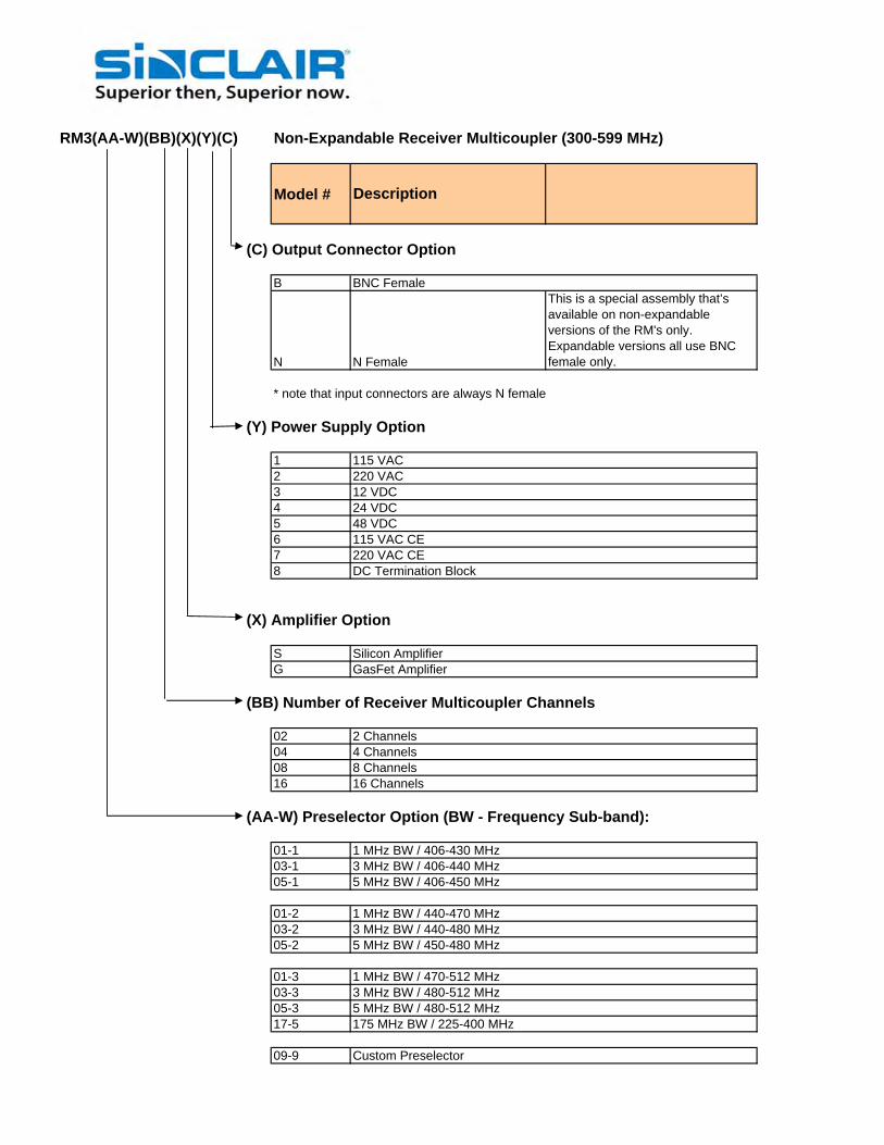
RM3(AA-W)(BB)(X)(Y)(C) Non-Expandable Receiver Multicoupler (300-599 MHz)
Model #
(C) Output Connector Option
B
N
This is a special assembly that’s available on non-expandable versions of the RM's only. Expandable versions all use BNC female only.
* note that input connectors are always N female
(Y) Power Supply Option
12345678
(X) Amplifier Option
SG
(BB) Number of Receiver Multicoupler Channels
02040816
(AA-W) Preselector Option (BW - Frequency Sub-band):
01-103-105-1
01-203-205-2
01-303-305-317-5
09-9 Custom Preselector
1 MHz BW / 470-512 MHz3 MHz BW / 480-512 MHz5 MHz BW / 480-512 MHz175 MHz BW / 225-400 MHz
5 MHz BW / 406-450 MHz
1 MHz BW / 440-470 MHz3 MHz BW / 440-480 MHz5 MHz BW / 450-480 MHz
8 Channels16 Channels
1 MHz BW / 406-430 MHz3 MHz BW / 406-440 MHz
Silicon AmplifierGasFet Amplifier
2 Channels4 Channels
12 VDC24 VDC48 VDC115 VAC CE220 VAC CEDC Termination Block
Description
N Female
BNC Female
115 VAC220 VAC

RM4(AA-W)E(BB)(X)(Y)(C) Expandable/Non-Expanbable Rx Multicoupler (600-999 MHz)
Model # Configuration # / Part Number
(C) Output Connector Option
B
N
This is a special assembly that’s available on non-expandable versions of the RM's only. Expandable versions all use BNC female only.
* note that input connectors are always N female
(Y) Power Supply Option
123456789
(X) Amplifier Option
G
(BB) Number of Receiver Multicoupler Channels
02040816* 12 channel not available, must use 16 with termiation loads
E Expandable Unit (available only for more than 20 channels)
(AA-W) Preselector Option (BW - Frequency Sub-band):
15-115-215-315-410-109-9 Custom Preselector
15 MHz BW / 821-849 MHz15 MHz BW / 850-865MHz15 MHz BW / 865-880 MHz9.6 MHz BW / 896-901 MHz
4 Channels8 Channels16 Channels
15 MHz BW / 806-821 MHz
DC Termination BlockLess Power Supply
GasFet Amplifier
2 Channels
24 VDC48 VDC115 VAC CE220 VAC CE
BNC Female
115 VAC220 VAC12 VDC
Description
N Female

TM3(AA-W)(D)(BB)(X)(Y)(C) Non-Expandable TTA Multicoupler (300-599 MHz)
Model #
(C) Output Connector Option
BN
* note that input connectors are always N female
(Y) Power Supply Option
1234567
(X) Amplifier Option
SG
(BB) Number of Receiver Multicoupler Channels
02040816
(D) Tower Mounted Unit Configuration OptionABC
(AA-W) Preselector Option (BW - Frequency Sub-band):
01-103-105-1
01-203-205-2
01-303-305-309-9
1 MHz BW / 470-512 MHz3 MHz BW / 480-512 MHz5 MHz BW / 480-512 MHzCustom Preselector
Description
1 MHz BW / 440-470 MHz3 MHz BW / 440-480 MHz5 MHz BW / 450-480 MHz
Redundant aplifier with relay bypass configuration
1 MHz BW / 406-430 MHz3 MHz BW / 406-440 MHz5 MHz BW / 406-450 MHz
8 Channels16 Channels
Standard Single Amplifier configurationSingle Amplifier with relay bypass configuration
Silicon AmplifierGasFet Amplifier
2 Channels4 Channels
12 VDC24 VDC48 VDC115 VAC CE
BNC FemaleN Female
115 VAC220 VAC
220 VAC CE

TM4(AA-W)(D)(BB)(X)(Y)(C) Non-Expanbable TTA (806-880 MHz)
Model #
(C) Output Connector Option
BN
* note that input connectors are always N female
(Y) Power Supply Option
1234567
(X) Amplifier Option
G
(BB) Number of Receiver Multicoupler Channels
02040816Note: add the E if an expandable version - blank if not expandable
(D) Tower Mounted Unit Configuration OptionABC
(AA-W) Preselector Option (BW - Frequency Sub-band):
15-115-215-315-409-9
15 MHz BW / 821-849 MHz15 MHz BW / 850-865MHz15 MHz BW / 865-880 MHzCustom Preselector
Standard Single Amplifier configurationSingle Amplifier with relay bypass configurationRedundant aplifier with relay bypass configuration
15 MHz BW / 806-821 MHz
2 Channels4 Channels8 Channels16 Channels
GasFet Amplifier
220 VAC CE115 VAC CE48 VDC24 VDC12 VDC220 VAC115 VAC
N FemaleBNC Female
Description
Low Band, Aviation, and VHF Product Catalogue
Table of Contents
Page
Region United States Europe, Middle East and Africa Caribbean and Latin America Canada and rest of the world
Telephone USA: 1 800 263 3275 International: +44 (0) 1223 42 03 03 International: +1 905 726 7676 Canada: 1 800 263 3275International: +1 905 727 0165
E-mail [email protected] [email protected] [email protected] [email protected]
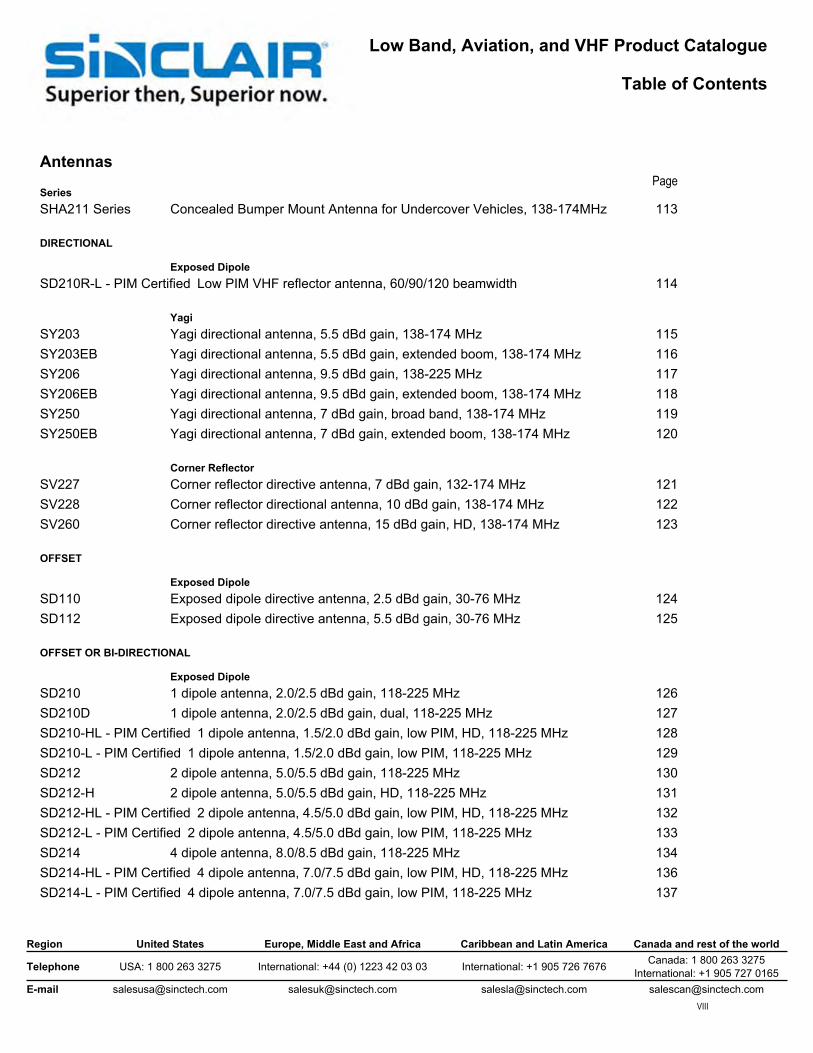
Antennas
SeriesSHA211 Series Concealed Bumper Mount Antenna for Undercover Vehicles, 138-174MHz 113
DIRECTIONAL
Exposed DipoleSD210R-L - PIM Certified Low PIM VHF reflector antenna, 60/90/120 beamwidth 114
YagiSY203 Yagi directional antenna, 5.5 dBd gain, 138-174 MHz 115SY203EB Yagi directional antenna, 5.5 dBd gain, extended boom, 138-174 MHz 116SY206 Yagi directional antenna, 9.5 dBd gain, 138-225 MHz 117SY206EB Yagi directional antenna, 9.5 dBd gain, extended boom, 138-174 MHz 118SY250 Yagi directional antenna, 7 dBd gain, broad band, 138-174 MHz 119SY250EB Yagi directional antenna, 7 dBd gain, extended boom, 138-174 MHz 120
Corner ReflectorSV227 Corner reflector directive antenna, 7 dBd gain, 132-174 MHz 121SV228 Corner reflector directional antenna, 10 dBd gain, 138-174 MHz 122SV260 Corner reflector directive antenna, 15 dBd gain, HD, 138-174 MHz 123
OFFSET
Exposed DipoleSD110 Exposed dipole directive antenna, 2.5 dBd gain, 30-76 MHz 124SD112 Exposed dipole directive antenna, 5.5 dBd gain, 30-76 MHz 125
OFFSET OR BI-DIRECTIONAL
Exposed DipoleSD210 1 dipole antenna, 2.0/2.5 dBd gain, 118-225 MHz 126SD210D 1 dipole antenna, 2.0/2.5 dBd gain, dual, 118-225 MHz 127SD210-HL - PIM Certified 1 dipole antenna, 1.5/2.0 dBd gain, low PIM, HD, 118-225 MHz 128SD210-L - PIM Certified 1 dipole antenna, 1.5/2.0 dBd gain, low PIM, 118-225 MHz 129SD212 2 dipole antenna, 5.0/5.5 dBd gain, 118-225 MHz 130SD212-H 2 dipole antenna, 5.0/5.5 dBd gain, HD, 118-225 MHz 131SD212-HL - PIM Certified 2 dipole antenna, 4.5/5.0 dBd gain, low PIM, HD, 118-225 MHz 132SD212-L - PIM Certified 2 dipole antenna, 4.5/5.0 dBd gain, low PIM, 118-225 MHz 133SD214 4 dipole antenna, 8.0/8.5 dBd gain, 118-225 MHz 134SD214-HL - PIM Certified 4 dipole antenna, 7.0/7.5 dBd gain, low PIM, HD, 118-225 MHz 136SD214-L - PIM Certified 4 dipole antenna, 7.0/7.5 dBd gain, low PIM, 118-225 MHz 137

Low Band, Aviation, and VHF Product Catalogue
Table of Contents
Page
Region United States Europe, Middle East and Africa Caribbean and Latin America Canada and rest of the world
Telephone USA: 1 800 263 3275 International: +44 (0) 1223 42 03 03 International: +1 905 726 7676 Canada: 1 800 263 3275International: +1 905 727 0165
E-mail [email protected] [email protected] [email protected] [email protected]
Antennas, continued
OFFSET OR BI-DIRECTIONAL, continued
Series Exposed Dipole, continuedSD218 8 dipole antenna, 11.0/11.5 dBd gain, 118-225 MHz 138SD218-L - PIM Certified 8 dipole antenna, 9.5/10 dBd gain, low PIM, 118-225 MHz 139
OMNI OR BI-DIRECTIONAL, ADJUSTABLE
Exposed DipoleSD235 Exposed dipole antenna array, 3/5.5 dBd gain, field adjustable, 118-174 MHz 140SD2352 Exposed dipole antenna array, 6/8.5 dBd gain, field adjustable, 118-174 MHz 141SD235D Exposed dipole array, 3/5.5 dBd gain, dual, 108-174 MHz 142SD235-H Exposed dipole antenna array, 3/5.5 dBd gain, HD, field adj., 118-138 MHz 143
OMNI OR OFFSET, ADJUSTABLE
Exposed DipoleSD222 Exposed dipole antenna, 3/6 dBd gain, field adjustable, 132-174 MHZ 144SD224 Exposed dipole antenna, 6/9 dBd gain, field adjustable, 132-174 MHz 145
OMNI-DIRECTIONAL
CollinearSC225M Collinear omni antenna, 0 dBd gain, 130-174 MHz 146SC225M-H Collinear omni antenna, 0 dBd gain, HD, 130-174 MHz 147SC229 Collinear omni antenna, 6 dBd gain, 138-225 MHz 148SC229-L - PIM Certified Collinear omni antenna, 6 dBd gain, low PIM, 138-174 MHz 149SC233 Collinear omni antenna, 3 dBd gain, 138-174 MHz 150SC272 Collinear omni antenna, 0 dBd gain, 118-137 MHz 151SC281-HL - PIM Certified Collinear omni antenna, 5 dBd gain, low PIM, HD, 138-174 MHz 152
Ground PlaneSG101 Ground plane omni antenna, 0 dBd gain, 30-88 MHz 153SG201 Ground plane omni antenna, 0 dBd gain, 118-174 MHz 154SG217 Ground plane omni antenna, 2.5 dBd gain, 118-174 MHz 155SG238 Ground plane omni antenna, 0 dBd gain, 118-174 MHz 156SG238-H Ground plane omni antenna, 0 dBd gain, HD, 118-174 MHz 157
Mobile/TransitST121R Mobile omnidirectional antenna, 0 dBd gain, low profile, 25-50 MHz 158ST221 Mobile omni antenna, 0 dBd gain, low profile, 138-222 MHz 159

Low Band, Aviation, and VHF Product Catalogue
Table of Contents
Page
Region United States Europe, Middle East and Africa Caribbean and Latin America Canada and rest of the world
Telephone USA: 1 800 263 3275 International: +44 (0) 1223 42 03 03 International: +1 905 726 7676 Canada: 1 800 263 3275International: +1 905 727 0165
E-mail [email protected] [email protected] [email protected] [email protected]
Antennas, continued
OMNI-DIRECTIONAL, continued
Series Mobile/Transit, continuedST221R Mobile omni antenna, 0 dBd gain, radome, 132-174 MHz 160SVB- Low Band Mobile omni antenna, 0 dBd gain, 27-30 MHz 161SVB- VHF Mobile omni antenna 162SVT- VHF Mobile omni antenna 163
AviationSC6172D Aviation band antenna, 1 dBi gain, dual feed, HD, 118-137 MHz 164SC6175D Aviation band antenna, 1 dBd gain, dual feed, HD, 118-137 & 225-400 MHz 165SC6185 Aviation band antenna, 0.9-2.9 dBd gain, HD, 225-400 MHz 166
Transmitter Combiners
CS2 VHF Combiner, cavity-ferrite, 8.5" 1/4 wave, 125W load 167TC2 Hybrid-Ferrite Transmitter Combiner 169TJ2 Cavity-Ferrite Transmitter Combiner, 7" Cans 170
Receiver Multicouplers
RM2 VHF Bipolar Receiver Mulitcoupler 171
Duplexers
MR2222 4 Cavity Extremely Compact VHF Mobile Duplexer 172MR2332 6 Cavity Extremely Compact High Isolation Mobile Duplexer 173MR254 4 Cavity Compact VHF Mobile Duplexer 174MR256 6 Cavity Compact VHF Mobile Duplexer 175P201 4 Cavity High Selectivity Bandpass Duplexer 176Q201G Q-Circuit 6 Cavity Base Station Duplexer 177Q202G Four Cavity Q-Circuit Base Station Duplexer 178Q2220 4 Cavity Res-Lok Q-Circuit VHF Duplexer 179Q2222 4 Cavity Compact Res-Lok Q-Circuit Duplexer 180Q2330 6 Cavity Res-Lok Q-Circuit VHF Duplexer 181

Low Band, Aviation, and VHF Product Catalogue
Table of Contents
Page
Region United States Europe, Middle East and Africa Caribbean and Latin America Canada and rest of the world
Telephone USA: 1 800 263 3275 International: +44 (0) 1223 42 03 03 International: +1 905 726 7676 Canada: 1 800 263 3275International: +1 905 727 0165
E-mail [email protected] [email protected] [email protected] [email protected]
Cavity Filters
SeriesFP20107 High-Q Bandpass Cavity Filter, Single 7" Can 182FP20207 Bandpass Cavity Filter, Two 7" Cans, 118-230 MHz 183FQ20107 Q Circuit Cavity Filter, Single 7" Can 184FR20107 Notch Cavity Filter, Single 7" Can 185
Preselector Filters
FP20401 Compact Surface Mounted 1 MHz Preselector 186FP20402 Preselector, UHF 130-170MHz, High Performance, N Male 187PH2040 Highly Versatile Res-Lok 1 or 2 MHz Preselector 188
Expandable Multicouplers
C2017P C Series Pass-Thru Expandable Multicoupler, 7" Cans 189C2027 C Series Pass-Reject Expandable Multicoupler, 7" Cans 190C2027P C Series Pass-Thru Expandable Multicoupler, 7" Cans 191C2034 Res-Lok Pass-Reject Expandable Multicoupler, 118-174 MHz 192C2037 C Series Pass-Reject Expandable Multicoupler, 7" Cans 193
Hybrid Couplers
HH1 Hybrid Coupler, 66-100 MHz 194HH2 Hybrid Coupler, 132-174 Band 195
Isolators and Circulators
I1 Compact, rugged Isolator/Circulator, 66-100 MHz 196I2 Compact Rugged Isolator/Circulator, 132-174 MHz 197
Intermod Supression Panels
PC2 Rack Mounted Ferrite Intermod Suppression Panel 199

VHF, UHF, 800 MHz, 1710-2500 MHz Product Catalogue
Table of Contents
Page
Region United States Europe, Middle East and Africa Caribbean and Latin America Canada and rest of the world
Telephone USA: 1 800 263 3275 International: +44 (0) 1223 42 03 03 International: +1 905 726 7676 Canada: 1 800 263 3275International: +1 905 727 0165
E-mail [email protected] [email protected] [email protected] [email protected]
Crossband Coupler
SeriesFX2300 series Multi-Service Cross-Band Coupler, 138-174/380-512MHz 201FX2400 series Multi-Service Cross-Band Coupler, 138-174/746-960MHz 202

AntennasLow Band, Aviation, and VHF Antennas
SHA211 Series
Concealed Bumper Mount Antenna for Undercover Vehicles, 138-174MHz• Completely hidden-does not need any existing vehicle antennas• Available in field tunable narrow band version or broadband version depending on the vehicle• Easy installation and tuning for optimum performance and durability• Applicable for both covert and overt law enforcement vehicles
Model DescriptionSHA211-SF1SNM Concealed Bumper Mount Antenna for Undercover Vehicles, 138-150MHzSHA211-SF2SNM Concealed Bumper Mount Antenna for Undercover Vehicles, 150-174MHz
The specifications listed below represent the entire product series.For specifications on a specific model, visit our web site at www.sinctech.com or view our CD catalogue.
Electrical SpecificationsBandwidth MHz 3Frequency Range MHz 138 to 174Gain (nominal) dBd (dBi) unity (2.1)Impedance Ω 50Input VSWR (max) 2:1Average power input (max) W 50
Mechanical SpecificationsLength/ Height in (mm) 28 (711)Shipping dimensions in (mm) 9x14x5 (229x356x127)Weight lbs (kg) 2 (0.9)Connector N (male)
Environmental SpecificationsTemperature range °F (°C) -40 to +140 (-40 to +60)
Ordering InformationPlease contact Sinclair CSR for your requirement on dual antennas(one in the front bumper and one in the rear)
Region United States Europe, Middle East and Africa Caribbean and Latin America Canada and rest of the world
Telephone USA: 1 800 263 3275 International: +44 (0) 1223 42 03 03 International: +1 905 726 7676 Canada: 1 800 263 3275International: +1 905 727 0165
E-mail [email protected] [email protected] [email protected] [email protected] Specification Sheet SHA211 Series Dated: 10-09-09
Sinclair’s commitment to product leadership may result in improvement or change to this productCopyright © Sinclair TechnologiesAN.ALV.1/87 Page 113/202
www.
sinct
ech.
com

AntennasLow Band, Aviation, and VHF Antennas
SD210R-L - PIM Certified Series
Low PIM VHF reflector antenna, 60/90/120 beamwidth• 60, 90, or 120 degrees horizontal beamwidth available for VHF simulcast applications• One, two or four bay stacked dipoles available for different gains• Broadband operation, covering 138-174 MHz full band• Unique design for low passive intermodulation
Model DescriptionSD210R-SF2P120LDF(D00S) Low PIM VHF reflector antenna, 120 degrees
beamwidth, 138-174MHzSD210R-SF2P60LDF(D00S) Low PIM VHF reflector antenna, 60 degrees
beamwidth, 138-174MHzSD210R-SF2P90LDF(D00S) Low PIM VHF reflector antenna, 90 degrees
beamwidth, 138-174MHz
The specifications listed below represent the entire product series.For specifications on a specific model, visit our web site at www.sinctech.com or view our CD catalogue.
Electrical SpecificationsBandwidth MHz 36Frequency Range MHz 138 to 174Polarization verticalGain (nominal) dBd (dBi) 12.5 (14.6)Impedance Ω 50Lightning protection DC groundPassive intermod. (2x20W, 3rd ord.) dBc -150Pattern DirectionalInput VSWR (max) 1.5:1Horizontal beamwidth degrees 60Vertical beamwidth degrees 18Front to back ratio dB 25Average power input (max) W 300
Mechanical SpecificationsLength/ Height in (mm) 240 (6096)Width in (mm) 92 (2337)Depth in (mm) 47 (1194)Weight lbs (kg) 161 (73.1)Actual Shipping weight lbs (kg) 246 (111.7)Connector 7/16 DIN (female)Weight iced lbs (kg) 457 (207.5)Base pipe diameter in (mm) 2.4 (60)Mounting information #6B clamps recommended. Order separately.
Environmental SpecificationsRated wind velocity (1/2" radial ice) mph (km/h) 85 (137)Rated wind velocity (no ice) mph (km/h) 105 (169)
Ordering InformationPlease contact Sinclair CSR to order mounting clamps.
Region United States Europe, Middle East and Africa Caribbean and Latin America Canada and rest of the world
Telephone USA: 1 800 263 3275 International: +44 (0) 1223 42 03 03 International: +1 905 726 7676 Canada: 1 800 263 3275International: +1 905 727 0165
E-mail [email protected] [email protected] [email protected] [email protected] Specification Sheet SD210R-L - PIM Certified Dated: 10-09-09
Sinclair’s commitment to product leadership may result in improvement or change to this productCopyright © Sinclair TechnologiesAN.ALV.2/87 Page 114/202
www.
sinct
ech.
com
AntennasLow Band, Aviation, and VHF Antennas
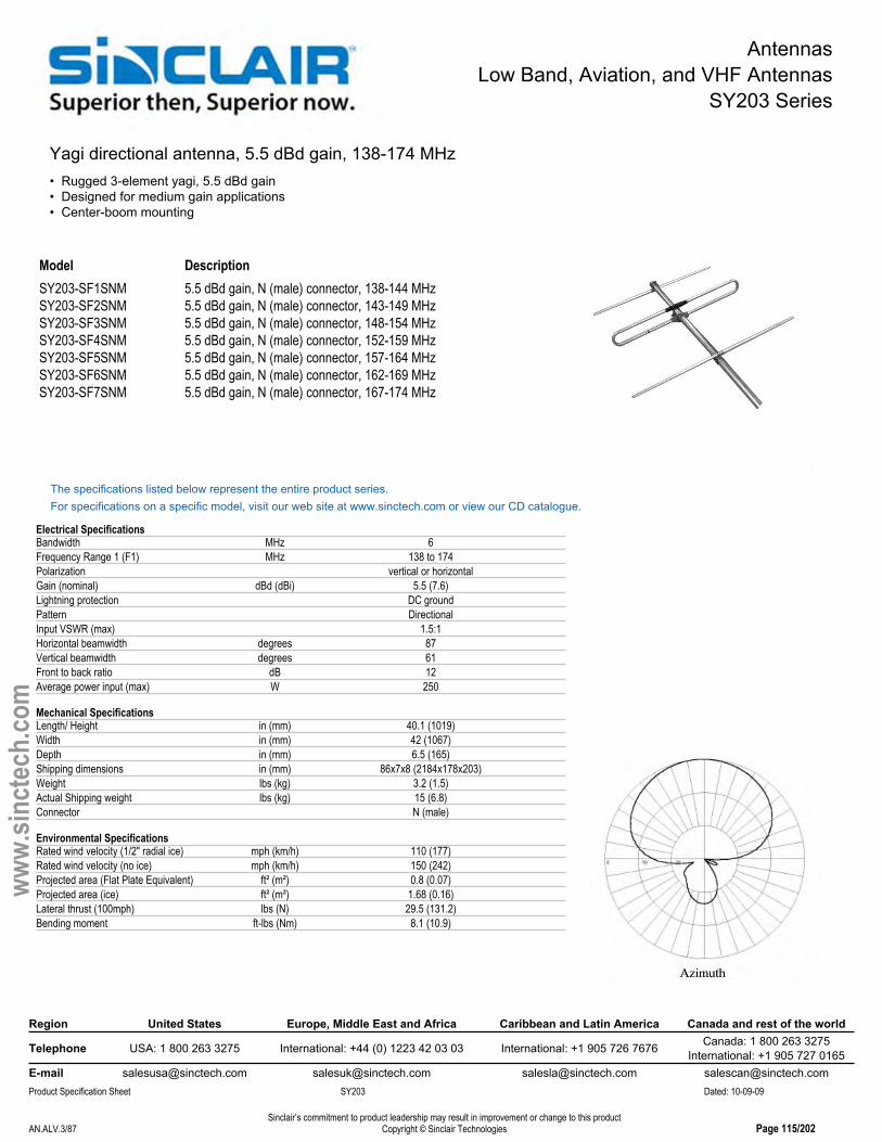
SY203 Series
Yagi directional antenna, 5.5 dBd gain, 138-174 MHz• Rugged 3-element yagi, 5.5 dBd gain• Designed for medium gain applications• Center-boom mounting
Model DescriptionSY203-SF1SNM 5.5 dBd gain, N (male) connector, 138-144 MHzSY203-SF2SNM 5.5 dBd gain, N (male) connector, 143-149 MHzSY203-SF3SNM 5.5 dBd gain, N (male) connector, 148-154 MHzSY203-SF4SNM 5.5 dBd gain, N (male) connector, 152-159 MHzSY203-SF5SNM 5.5 dBd gain, N (male) connector, 157-164 MHzSY203-SF6SNM 5.5 dBd gain, N (male) connector, 162-169 MHzSY203-SF7SNM 5.5 dBd gain, N (male) connector, 167-174 MHz
The specifications listed below represent the entire product series.For specifications on a specific model, visit our web site at www.sinctech.com or view our CD catalogue.
Electrical SpecificationsBandwidth MHz 6Frequency Range 1 (F1) MHz 138 to 174Polarization vertical or horizontalGain (nominal) dBd (dBi) 5.5 (7.6)Lightning protection DC groundPattern DirectionalInput VSWR (max) 1.5:1Horizontal beamwidth degrees 87Vertical beamwidth degrees 61Front to back ratio dB 12Average power input (max) W 250
Mechanical SpecificationsLength/ Height in (mm) 40.1 (1019)Width in (mm) 42 (1067)Depth in (mm) 6.5 (165)Shipping dimensions in (mm) 86x7x8 (2184x178x203)Weight lbs (kg) 3.2 (1.5)Actual Shipping weight lbs (kg) 15 (6.8)Connector N (male)
Environmental SpecificationsRated wind velocity (1/2" radial ice) mph (km/h) 110 (177)Rated wind velocity (no ice) mph (km/h) 150 (242)Projected area (Flat Plate Equivalent) ft² (m²) 0.8 (0.07)Projected area (ice) ft² (m²) 1.68 (0.16)Lateral thrust (100mph) lbs (N) 29.5 (131.2)Bending moment ft-lbs (Nm) 8.1 (10.9)
Region United States Europe, Middle East and Africa Caribbean and Latin America Canada and rest of the world
Telephone USA: 1 800 263 3275 International: +44 (0) 1223 42 03 03 International: +1 905 726 7676 Canada: 1 800 263 3275International: +1 905 727 0165
E-mail [email protected] [email protected] [email protected] [email protected] Specification Sheet SY203 Dated: 10-09-09
Sinclair’s commitment to product leadership may result in improvement or change to this productCopyright © Sinclair TechnologiesAN.ALV.3/87 Page 115/202
www.
sinct
ech.
com
AntennasLow Band, Aviation, and VHF Antennas
SY203EB Series
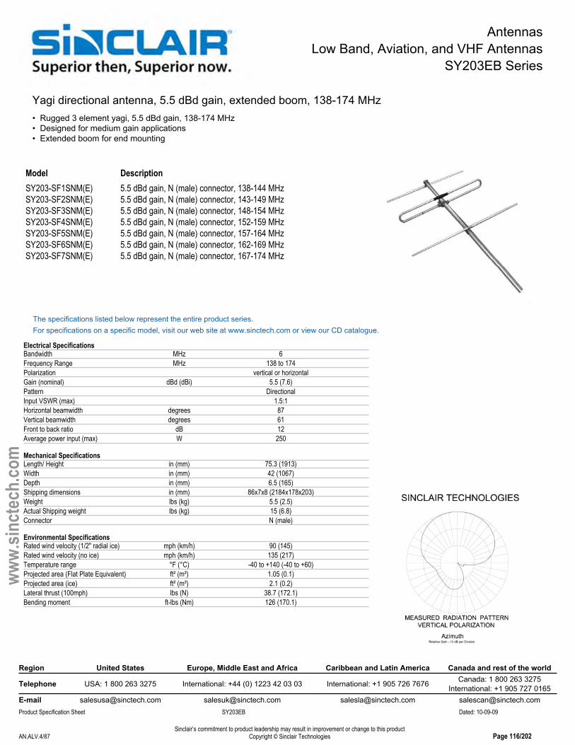
Yagi directional antenna, 5.5 dBd gain, extended boom, 138-174 MHz• Rugged 3 element yagi, 5.5 dBd gain, 138-174 MHz• Designed for medium gain applications• Extended boom for end mounting
Model DescriptionSY203-SF1SNM(E) 5.5 dBd gain, N (male) connector, 138-144 MHzSY203-SF2SNM(E) 5.5 dBd gain, N (male) connector, 143-149 MHzSY203-SF3SNM(E) 5.5 dBd gain, N (male) connector, 148-154 MHzSY203-SF4SNM(E) 5.5 dBd gain, N (male) connector, 152-159 MHzSY203-SF5SNM(E) 5.5 dBd gain, N (male) connector, 157-164 MHzSY203-SF6SNM(E) 5.5 dBd gain, N (male) connector, 162-169 MHzSY203-SF7SNM(E) 5.5 dBd gain, N (male) connector, 167-174 MHz
The specifications listed below represent the entire product series.For specifications on a specific model, visit our web site at www.sinctech.com or view our CD catalogue.
Electrical SpecificationsBandwidth MHz 6Frequency Range MHz 138 to 174Polarization vertical or horizontalGain (nominal) dBd (dBi) 5.5 (7.6)Pattern DirectionalInput VSWR (max) 1.5:1Horizontal beamwidth degrees 87Vertical beamwidth degrees 61Front to back ratio dB 12Average power input (max) W 250
Mechanical SpecificationsLength/ Height in (mm) 75.3 (1913)Width in (mm) 42 (1067)Depth in (mm) 6.5 (165)Shipping dimensions in (mm) 86x7x8 (2184x178x203)Weight lbs (kg) 5.5 (2.5)Actual Shipping weight lbs (kg) 15 (6.8)Connector N (male)
Environmental SpecificationsRated wind velocity (1/2" radial ice) mph (km/h) 90 (145)Rated wind velocity (no ice) mph (km/h) 135 (217)Temperature range °F (°C) -40 to +140 (-40 to +60)Projected area (Flat Plate Equivalent) ft² (m²) 1.05 (0.1)Projected area (ice) ft² (m²) 2.1 (0.2)Lateral thrust (100mph) lbs (N) 38.7 (172.1)Bending moment ft-lbs (Nm) 126 (170.1)
Region United States Europe, Middle East and Africa Caribbean and Latin America Canada and rest of the world
Telephone USA: 1 800 263 3275 International: +44 (0) 1223 42 03 03 International: +1 905 726 7676 Canada: 1 800 263 3275International: +1 905 727 0165
E-mail [email protected] [email protected] [email protected] [email protected] Specification Sheet SY203EB Dated: 10-09-09
Sinclair’s commitment to product leadership may result in improvement or change to this productCopyright © Sinclair TechnologiesAN.ALV.4/87 Page 116/202
www.
sinct
ech.
com

AntennasLow Band, Aviation, and VHF Antennas
SY206 Series
Yagi directional antenna, 9.5 dBd gain, 138-225 MHz• Six element yagi• Outstanding durability and performance• DC ground potential for lightning protection
Model DescriptionSY206-SF1SNM Yagi directional antenna, 9.5 dBd gain, 148-152 MHzSY206-SF2SNM Yagi directional antenna, 9.5 dBd gain, 152-159 MHzSY206-SF3SNM Yagi directional antenna, 9.5 dBd gain, 157-164 MHzSY206-SF4SNM Yagi directional antenna, 9.5 dBd gain, 162-169 MHzSY206-SF5SNM Yagi directional antenna, 9.5 dBd gain, 167-174 MHzSY206-SF6SNM Yagi directional antenna, 9.5 dBd gain, 138-143 MHzSY206-SF7SNM Yagi directional antenna, 9.5 dBd gain, 143-148 MHz
The specifications listed below represent the entire product series.For specifications on a specific model, visit our web site at www.sinctech.com or view our CD catalogue.
Electrical SpecificationsBandwidth MHz 4Frequency Range 1 (F1) MHz 138 to 225Polarization vertical or horizontalGain (nominal) dBd (dBi) 9.5 (11.6)Lightning protection DC groundPattern DirectionalInput VSWR (max) 1.5:1Horizontal beamwidth degrees 56Vertical beamwidth degrees 46Front to back ratio dB 17Average power input (max) W 175
Mechanical SpecificationsLength/ Height in (mm) 80.9 (2055)Width in (mm) 42.2 (1071)Depth in (mm) 5.8 (146)Shipping dimensions in (mm) 84.8x48x6 (2154x1219x152)Weight lbs (kg) 12.5 (5.7)Actual Shipping weight lbs (kg) 41 (18.6)Connector N (male)Weight iced lbs (kg) 34.4 (15.6)Base pipe diameter in (mm) 1.5 (38)Mounting hardware #1 Clamp
Environmental SpecificationsRated wind velocity (1/2" radial ice) mph (km/h) 85 (137)Rated wind velocity (no ice) mph (km/h) 145 (233)Temperature range °F (°C) -40 to +140 (-40 to +60)
Region United States Europe, Middle East and Africa Caribbean and Latin America Canada and rest of the world
Telephone USA: 1 800 263 3275 International: +44 (0) 1223 42 03 03 International: +1 905 726 7676 Canada: 1 800 263 3275International: +1 905 727 0165
E-mail [email protected] [email protected] [email protected] [email protected] Specification Sheet SY206 Dated: 10-09-09
Sinclair’s commitment to product leadership may result in improvement or change to this productCopyright © Sinclair TechnologiesAN.ALV.5/87 Page 117/202
www.
sinct
ech.
com

AntennasLow Band, Aviation, and VHF Antennas
SY206EB Series
Yagi directional antenna, 9.5 dBd gain, extended boom, 138-174 MHz• Six element extended boom yagi• Outstanding durability and performance• DC grounded for lightning protection
Model DescriptionSY206-SF10SNM(E2272) 8 dBd gain, N (male) connector, 108-118 MHzSY206-SF1SNM(E) 9.5 dBd gain, N (male) connector, 148-152 MHzSY206-SF2SNM(E) 9.5 dBd gain, N (male) connector, 152-159 MHzSY206-SF3SNM(E) 9.5 dBd gain, N (male) connector, 157-164 MHzSY206-SF4SNM(E) 9.5 dBd gain, N (male) connector, 162-169 MHzSY206-SF5SNM(E) 9.5 dBd gain, N (male) connector, 167-174 MHzSY206-SF6SNM(E) 9.5 dBd gain, N (male) connector, 138-143 MHzSY206-SF7SNM(E) 9.5 dBd gain, N (male) connector, 143-148 MHzSY2066-HF9SNM(E-HT-ABK) 6 Yagi array, 15.5 dBd gain, heated elements,
Ext. boom 130-136 MHz
The specifications listed below represent the entire product series.For specifications on a specific model, visit our web site at www.sinctech.com or view our CD catalogue.
Electrical SpecificationsFrequency Range MHz 138 to 174Polarization vertical or horizontalGain (nominal) dBd (dBi) 9.5 (11.6)Lightning protection DC groundPattern DirectionalInput VSWR (max) 1.5:1Horizontal beamwidth degrees 56Vertical beamwidth degrees 46Front to back ratio dB 17Average power input (max) W 250
Mechanical SpecificationsLength/ Height in (mm) 113.4 (2880)Width in (mm) 42 (1067)Depth in (mm) 6.1 (155)Shipping dimensions in (mm) 124.8x48x6 (3170x1219x152)Weight lbs (kg) 12.5 (5.7)Actual Shipping weight lbs (kg) 45 (20.4)Connector N (male)Weight iced lbs (kg) 43.5 (19.7)
Environmental SpecificationsRated wind velocity (1/2" radial ice) mph (km/h) 85 (137)Rated wind velocity (no ice) mph (km/h) 130 (209)Temperature range °F (°C) -40 to +140 (-40 to +60)Projected area (Flat Plate Equivalent) ft² (m²) 1.92 (0.18)Projected area (ice) ft² (m²) 3.75 (0.35)Lateral thrust (100mph) lbs (N) 72 (320.3)
Region United States Europe, Middle East and Africa Caribbean and Latin America Canada and rest of the world
Telephone USA: 1 800 263 3275 International: +44 (0) 1223 42 03 03 International: +1 905 726 7676 Canada: 1 800 263 3275International: +1 905 727 0165
E-mail [email protected] [email protected] [email protected] [email protected] Specification Sheet SY206EB Dated: 10-09-09
Sinclair’s commitment to product leadership may result in improvement or change to this productCopyright © Sinclair TechnologiesAN.ALV.6/87 Page 118/202
www.
sinct
ech.
com

AntennasLow Band, Aviation, and VHF Antennas
SY250 Series
Yagi directional antenna, 7 dBd gain, broad band, 138-174 MHz• Extremely wide bandwidth makes these antennas an excellent stocking item• Specially designed for applications requiring extra broadband operation• Suitable for applications in icing and hoarfrost conditions
Model DescriptionSY250-SFXSNM 7 dBd gain, N (male) connector, 138-174 MHz
The specifications listed below represent the entire product series.For specifications on a specific model, visit our web site at www.sinctech.com or view our CD catalogue.
Electrical SpecificationsBandwidth MHz 36Frequency Range MHz 138 to 174Polarization vertical or horizontalGain (nominal) dBd (dBi) 7 (9.1)Lightning protection DC groundPattern DirectionalInput VSWR (max) 2:1Horizontal beamwidth degrees 80Vertical beamwidth degrees 60Front to back ratio dB 10
Mechanical SpecificationsLength/ Height in (mm) 80 (2032)Shipping dimensions in (mm) 111x7x44 (2819x178x1118)Weight lbs (kg) 12 (5.4)Actual Shipping weight lbs (kg) 45 (20.4)Connector N (male)Mounting hardware #1 Clamp
Environmental SpecificationsRated wind velocity (1/2" radial ice) mph (km/h) 85 (137)Rated wind velocity (no ice) mph (km/h) 100 (161)Projected area (Flat Plate Equivalent) ft² (m²) 1.45 (0.13)Lateral thrust (100mph) lbs (N) 87 (387)Torsional moment ft-lbs (Nm) 184 (248.4)
Region United States Europe, Middle East and Africa Caribbean and Latin America Canada and rest of the world
Telephone USA: 1 800 263 3275 International: +44 (0) 1223 42 03 03 International: +1 905 726 7676 Canada: 1 800 263 3275International: +1 905 727 0165
E-mail [email protected] [email protected] [email protected] [email protected] Specification Sheet SY250 Dated: 10-09-09
Sinclair’s commitment to product leadership may result in improvement or change to this productCopyright © Sinclair TechnologiesAN.ALV.7/87 Page 119/202
www.
sinct
ech.
com

AntennasLow Band, Aviation, and VHF Antennas
SY250EB Series
Yagi directional antenna, 7 dBd gain, extended boom, 138-174 MHz• Extremely wide bandwidth makes these antennas an excellent stocking item• Specially designed for applications requiring extra broadband operation• Designed for icing and hoarfrost conditions
Model DescriptionSY250-SFXSNM(E) 7 dBd gain, Extended boom, N (male) connector, 138-174 MHz
The specifications listed below represent the entire product series.For specifications on a specific model, visit our web site at www.sinctech.com or view our CD catalogue.
Electrical SpecificationsBandwidth MHz 36Frequency Range MHz 138 to 174Polarization vertical or horizontalGain (nominal) dBd (dBi) 7 (9.1)Lightning protection DC groundPattern DirectionalInput VSWR (max) 2:1Horizontal beamwidth degrees 80Vertical beamwidth degrees 60Front to back ratio dB 10
Mechanical SpecificationsLength/ Height in (mm) 108 (2743)Shipping dimensions in (mm) 111x7x44 (2819x178x1118)Weight lbs (kg) 12 (5.4)Actual Shipping weight lbs (kg) 55 (25)Connector N (male)
Environmental SpecificationsRated wind velocity (1/2" radial ice) mph (km/h) 85 (137)Rated wind velocity (no ice) mph (km/h) 100 (161)Projected area (Flat Plate Equivalent) ft² (m²) 1.5 (0.14)Lateral thrust (100mph) lbs (N) 87 (387)Torsional moment ft-lbs (Nm) 184 (248.4)
Region United States Europe, Middle East and Africa Caribbean and Latin America Canada and rest of the world
Telephone USA: 1 800 263 3275 International: +44 (0) 1223 42 03 03 International: +1 905 726 7676 Canada: 1 800 263 3275International: +1 905 727 0165
E-mail [email protected] [email protected] [email protected] [email protected] Specification Sheet SY250EB Dated: 10-09-09
Sinclair’s commitment to product leadership may result in improvement or change to this productCopyright © Sinclair TechnologiesAN.ALV.8/87 Page 120/202
www.
sinct
ech.
com

AntennasLow Band, Aviation, and VHF Antennas
SV227 Series
Corner reflector directive antenna, 7 dBd gain, 132-174 MHz• Folded dipole feed permits operation in severe conditions• High power and heavy duty models available• VSWR will not exceed 2.0:1 even with 0.5 in. of radial ice
Model DescriptionSV227-SF1SNM 7 dBd gain, N (male) connector, 130-150 MHzSV227-SF2SNM 7 dBd gain, N (male) connector, 148-174 MHz
The specifications listed below represent the entire product series.For specifications on a specific model, visit our web site at www.sinctech.com or view our CD catalogue.
Electrical SpecificationsFrequency Range MHz 132 to 174Polarization vertical or horizontalGain (nominal) dBd (dBi) 7 (9.1)Lightning protection DC groundPattern DirectionalInput VSWR (max) 1.5:1Horizontal beamwidth degrees 67Vertical beamwidth degrees 75Front to back ratio dB 30Average power input (max) W 250
Mechanical SpecificationsLength/ Height in (mm) 55.3 (1405)Width in (mm) 85 (2159)Depth in (mm) 60 (1524)Shipping dimensions in (mm) 120x7x17 (3048x178x432)Weight lbs (kg) 14 (6.4)Actual Shipping weight lbs (kg) 75 (34.1)Connector N (male)Weight iced lbs (kg) 119 (54)Radiating element material aluminumMounting hardware #4 clamp
Environmental SpecificationsRated wind velocity (1/2" radial ice) mph (km/h) 90 (145)Rated wind velocity (no ice) mph (km/h) 130 (209)Temperature range °F (°C) -40 to +140 (-40 to +60)Projected area (Flat Plate Equivalent) ft² (m²) 9.3 (0.86)
Ordering InformationFor the standard duty units, please specify which sub-band you require:F1- 130-150 MHz; F2- 148-174 MHz
Region United States Europe, Middle East and Africa Caribbean and Latin America Canada and rest of the world
Telephone USA: 1 800 263 3275 International: +44 (0) 1223 42 03 03 International: +1 905 726 7676 Canada: 1 800 263 3275International: +1 905 727 0165
E-mail [email protected] [email protected] [email protected] [email protected] Specification Sheet SV227 Dated: 10-09-09
Sinclair’s commitment to product leadership may result in improvement or change to this productCopyright © Sinclair TechnologiesAN.ALV.9/87 Page 121/202
www.
sinct
ech.
com
AntennasLow Band, Aviation, and VHF Antennas
SV228 Series
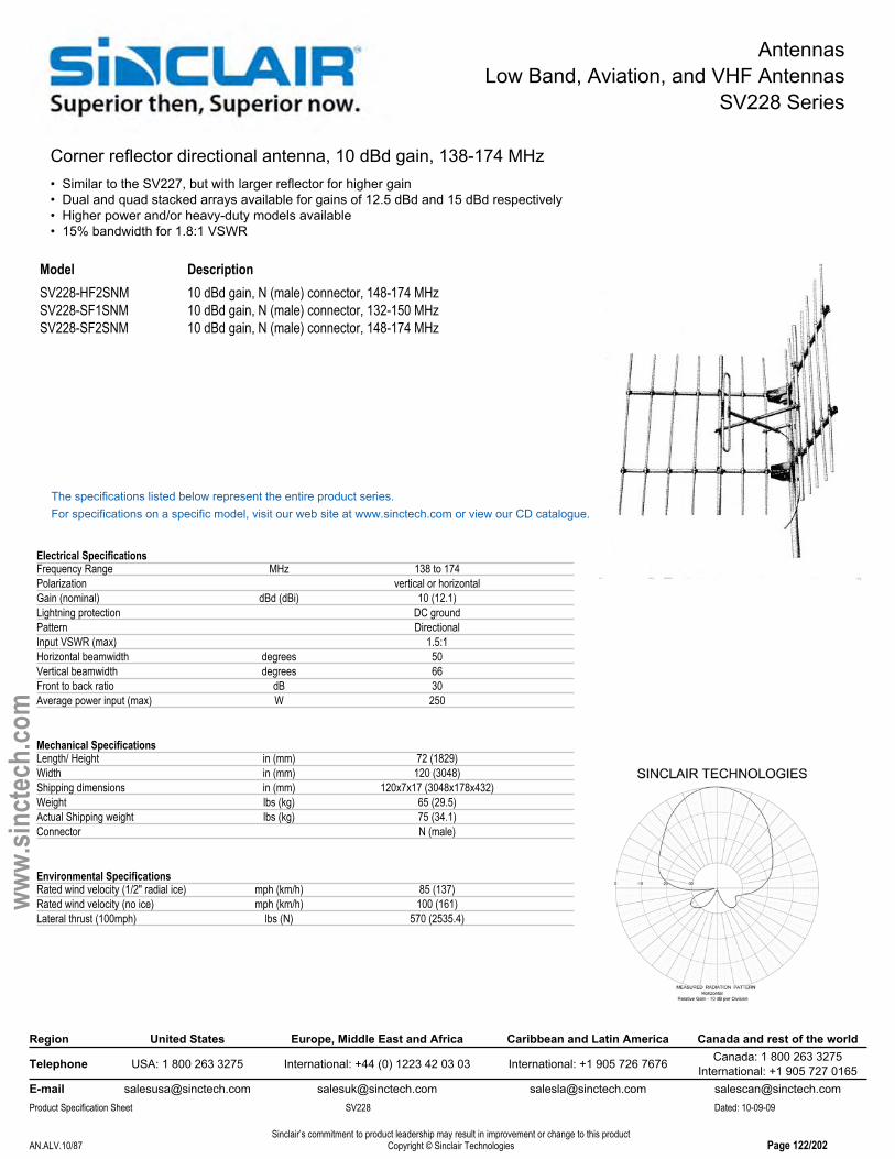
Corner reflector directional antenna, 10 dBd gain, 138-174 MHz• Similar to the SV227, but with larger reflector for higher gain• Dual and quad stacked arrays available for gains of 12.5 dBd and 15 dBd respectively• Higher power and/or heavy-duty models available• 15% bandwidth for 1.8:1 VSWR
Model DescriptionSV228-HF2SNM 10 dBd gain, N (male) connector, 148-174 MHzSV228-SF1SNM 10 dBd gain, N (male) connector, 132-150 MHzSV228-SF2SNM 10 dBd gain, N (male) connector, 148-174 MHz
The specifications listed below represent the entire product series.For specifications on a specific model, visit our web site at www.sinctech.com or view our CD catalogue.
Electrical SpecificationsFrequency Range MHz 138 to 174Polarization vertical or horizontalGain (nominal) dBd (dBi) 10 (12.1)Lightning protection DC groundPattern DirectionalInput VSWR (max) 1.5:1Horizontal beamwidth degrees 50Vertical beamwidth degrees 66Front to back ratio dB 30Average power input (max) W 250
Mechanical SpecificationsLength/ Height in (mm) 72 (1829)Width in (mm) 120 (3048)Shipping dimensions in (mm) 120x7x17 (3048x178x432)Weight lbs (kg) 65 (29.5)Actual Shipping weight lbs (kg) 75 (34.1)Connector N (male)
Environmental SpecificationsRated wind velocity (1/2" radial ice) mph (km/h) 85 (137)Rated wind velocity (no ice) mph (km/h) 100 (161)Lateral thrust (100mph) lbs (N) 570 (2535.4)
Region United States Europe, Middle East and Africa Caribbean and Latin America Canada and rest of the world
Telephone USA: 1 800 263 3275 International: +44 (0) 1223 42 03 03 International: +1 905 726 7676 Canada: 1 800 263 3275International: +1 905 727 0165
E-mail [email protected] [email protected] [email protected] [email protected] Specification Sheet SV228 Dated: 10-09-09
Sinclair’s commitment to product leadership may result in improvement or change to this productCopyright © Sinclair TechnologiesAN.ALV.10/87 Page 122/202
www.
sinct
ech.
com

AntennasLow Band, Aviation, and VHF Antennas
SV260 Series
Corner reflector directive antenna, 15 dBd gain, HD, 138-174 MHz• Parabolic cylinder reflector operating in the 138-174 MHz frequency range• Practical for a variety of different applications• Available only by special order
Model Description
The specifications listed below represent the entire product series.For specifications on a specific model, visit our web site at www.sinctech.com or view our CD catalogue.
Electrical SpecificationsFrequency Range MHz 138 to 174Polarization vertical or horizontalGain (nominal) dBd (dBi) 15 (17.1)Lightning protection DC groundPattern DirectionalInput VSWR (max) 1.5:1Average power input (max) W 250
Mechanical SpecificationsLength/ Height in (mm) 216 (5486)Width in (mm) 108 (2743)Depth in (mm) 54 (1372)Shipping dimensions in (mm) 47x9x43 (1194x229x1092)Weight lbs (kg) 185 (84)Actual Shipping weight lbs (kg) 50 (22.7)Connector N (male)Radiating element material aluminumMounting hardware #4 clamp
Environmental SpecificationsRated wind velocity (1/2" radial ice) mph (km/h) 85 (137)Rated wind velocity (no ice) mph (km/h) 100 (161)Temperature range °F (°C) -22 to +140 (-30 to +60)
Ordering InformationPlease specify center frequency upon order. This Antenna has a 5% bandwidth at 1.5:1 VSWR.
Region United States Europe, Middle East and Africa Caribbean and Latin America Canada and rest of the world
Telephone USA: 1 800 263 3275 International: +44 (0) 1223 42 03 03 International: +1 905 726 7676 Canada: 1 800 263 3275International: +1 905 727 0165
E-mail [email protected] [email protected] [email protected] [email protected] Specification Sheet SV260 Dated: 10-09-09
Sinclair’s commitment to product leadership may result in improvement or change to this productCopyright © Sinclair TechnologiesAN.ALV.11/87 Page 123/202
www.
sinct
ech.
com

AntennasLow Band, Aviation, and VHF Antennas
SD110 Series
Exposed dipole directive antenna, 2.5 dBd gain, 30-76 MHz• Covers 30-76 MHz in 0.5 MHz Increments, this antenna has a 10% BW at 1.5:1 VSWR.• 2.5 dBd gain, offset pattern (1/8 wave)• 100 mph wind velocity• 300 Watts power handling
Model DescriptionSD110-SFXPASNM 2.5 dBd gain, N (male) connector, 30-76 MHz
The specifications listed below represent the entire product series.For specifications on a specific model, visit our web site at www.sinctech.com or view our CD catalogue.
Electrical SpecificationsFrequency Range MHz 30 to 76Polarization verticalGain (nominal) dBd (dBi) 2.5 (4.6)Lightning protection DC groundPattern OffsetInput VSWR (max) 1.5:1Vertical beamwidth degrees 68Average power input (max) W 300
Mechanical SpecificationsLength/ Height in (mm) 190 (4826)Shipping dimensions in (mm) 195x4x55 (4953x102x1397)Weight lbs (kg) 25 (11.4)Actual Shipping weight lbs (kg) 45 (20.4)Connector N (male)
Environmental SpecificationsRated wind velocity (1/2" radial ice) mph (km/h) 85 (137)Rated wind velocity (no ice) mph (km/h) 100 (161)Lateral thrust (100mph) lbs (N) 200 (889.6)
Region United States Europe, Middle East and Africa Caribbean and Latin America Canada and rest of the world
Telephone USA: 1 800 263 3275 International: +44 (0) 1223 42 03 03 International: +1 905 726 7676 Canada: 1 800 263 3275International: +1 905 727 0165
E-mail [email protected] [email protected] [email protected] [email protected] Specification Sheet SD110 Dated: 10-09-09
Sinclair’s commitment to product leadership may result in improvement or change to this productCopyright © Sinclair TechnologiesAN.ALV.12/87 Page 124/202
www.
sinct
ech.
com
AntennasLow Band, Aviation, and VHF Antennas
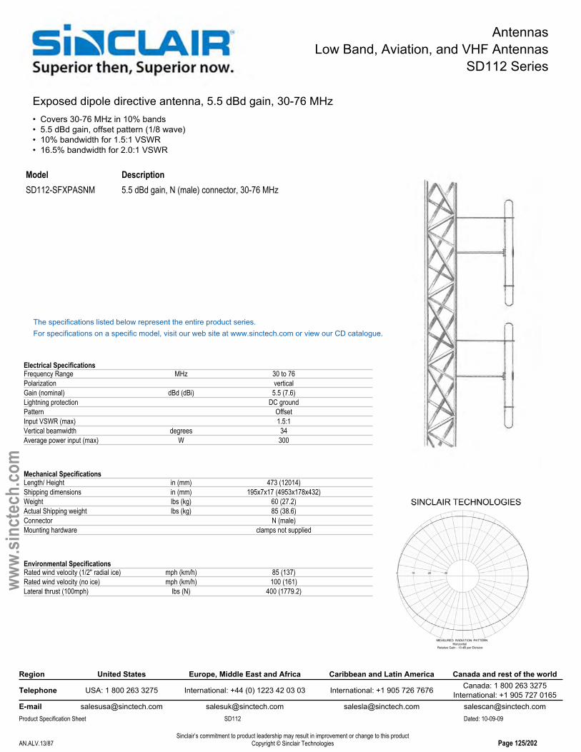
SD112 Series
Exposed dipole directive antenna, 5.5 dBd gain, 30-76 MHz• Covers 30-76 MHz in 10% bands• 5.5 dBd gain, offset pattern (1/8 wave)• 10% bandwidth for 1.5:1 VSWR• 16.5% bandwidth for 2.0:1 VSWR
Model DescriptionSD112-SFXPASNM 5.5 dBd gain, N (male) connector, 30-76 MHz
The specifications listed below represent the entire product series.For specifications on a specific model, visit our web site at www.sinctech.com or view our CD catalogue.
Electrical SpecificationsFrequency Range MHz 30 to 76Polarization verticalGain (nominal) dBd (dBi) 5.5 (7.6)Lightning protection DC groundPattern OffsetInput VSWR (max) 1.5:1Vertical beamwidth degrees 34Average power input (max) W 300
Mechanical SpecificationsLength/ Height in (mm) 473 (12014)Shipping dimensions in (mm) 195x7x17 (4953x178x432)Weight lbs (kg) 60 (27.2)Actual Shipping weight lbs (kg) 85 (38.6)Connector N (male)Mounting hardware clamps not supplied
Environmental SpecificationsRated wind velocity (1/2" radial ice) mph (km/h) 85 (137)Rated wind velocity (no ice) mph (km/h) 100 (161)Lateral thrust (100mph) lbs (N) 400 (1779.2)
Region United States Europe, Middle East and Africa Caribbean and Latin America Canada and rest of the world
Telephone USA: 1 800 263 3275 International: +44 (0) 1223 42 03 03 International: +1 905 726 7676 Canada: 1 800 263 3275International: +1 905 727 0165
E-mail [email protected] [email protected] [email protected] [email protected] Specification Sheet SD112 Dated: 10-09-09
Sinclair’s commitment to product leadership may result in improvement or change to this productCopyright © Sinclair TechnologiesAN.ALV.13/87 Page 125/202
www.
sinct
ech.
com

AntennasLow Band, Aviation, and VHF Antennas
SD210 Series
1 dipole antenna, 2.0/2.5 dBd gain, 118-225 MHz• Covers 118-225 MHz in 3 band splits• 2.0 dBd gain in elliptical (bi-directional) pattern (1/2 wave), 2.5 dBd gain in offset pattern (1/4 wave)• 228 mph/ 367 kph survival wind rating• Recommend using an SMK-125-A3 side mounting kit
Model DescriptionSD210-HF1P4SNM(D0B) 1 dipole antenna, 2 dBd gain, offset, 118-138 MHzSD210-HF2P2SNM 2.0 dBd gain, elliptical, N (male) connector, 138-174 MHzSD210-SF1P2SNM 2.0 dBd gain, elliptical, N (male) connector, 118-138 MHzSD210-SF1P4SNM 2.5 dBd gain, offset, N (male) connector, 118-138 MHzSD210-SF2P2SNM 2.0 dBd gain, elliptical, N (male) connector, 138-174 MHzSD210-SF2P4SNM 2.5 dBd gain, offset, N (male) connector, 138-174 MHzSD210-SF2PASNM 2.0/2.5 dBd gain, field adjustable, N (male) connector, 138-174 MHz
The specifications listed below represent the entire product series.For specifications on a specific model, visit our web site at www.sinctech.com or view our CD catalogue.
Electrical SpecificationsFrequency Range MHz 118 to 174Polarization verticalGain (nominal) dBd (dBi) 2.5 (4.6)Lightning protection DC groundPattern Offset or Bi-directionalInput VSWR (max) 1.5:1Horizontal beamwidth degrees 210Vertical beamwidth degrees 68Average power input (max) W 200
Mechanical SpecificationsLength/ Height in (mm) 60 (1524)Width in (mm) 21 (533)Depth in (mm) 3 (76)Shipping dimensions in (mm) 63x4x42 (1600x102x1067)Weight lbs (kg) 8.3 (3.8)Actual Shipping weight lbs (kg) 15 (6.8)Connector N (male)Base pipe diameter in (mm) 1.9 (48)Base pipe mounting length in (mm) 24 (610)Mounting hardware Clamps not supplied.
Environmental SpecificationsRated wind velocity (1/2" radial ice) mph (km/h) 85 (137)Rated wind velocity (no ice) mph (km/h) 175 (282)Projected area (Flat Plate Equivalent) ft² (m²) 0.89 (0.08)Projected area (ice) ft² (m²) 1.6 (0.15)Lateral thrust (100mph) lbs (N) 55 (244.6)
Ordering InformationSpecify required frequency, pattern and connector option when ordering.2 x #130 clamps recommended (not included).Recommend using an SMK-125-A3 side mounting kit
Region United States Europe, Middle East and Africa Caribbean and Latin America Canada and rest of the world
Telephone USA: 1 800 263 3275 International: +44 (0) 1223 42 03 03 International: +1 905 726 7676 Canada: 1 800 263 3275International: +1 905 727 0165
E-mail [email protected] [email protected] [email protected] [email protected] Specification Sheet SD210 Dated: 10-09-09
Sinclair’s commitment to product leadership may result in improvement or change to this productCopyright © Sinclair TechnologiesAN.ALV.14/87 Page 126/202
www.
sinct
ech.
com

AntennasLow Band, Aviation, and VHF Antennas
SD210D Series
1 dipole antenna, 2.0/2.5 dBd gain, dual, 118-225 MHz• Covers 118-225 MHz in 3 band splits• 2.0dBd gain, elliptical (bi-directional) pattern (1/2w ave), 2.5dBd gain, offset pattern (1/4 wave)• 200W power handling
Model DescriptionSD210D-SF2P2SNM 1 dipole antenna, 2.0 dBd gain, dual, elliptical, 138-174 MHzSD210D-SF2P4SNM 2.5 dBd gain, dual, offset, 138-174 MHz
The specifications listed below represent the entire product series.For specifications on a specific model, visit our web site at www.sinctech.com or view our CD catalogue.
Electrical SpecificationsBandwidth MHz 36Frequency Range MHz 118 to 225Polarization verticalLightning protection DC groundPattern Offset or Bi-directionalInput VSWR (max) 1.5:1Horizontal beamwidth degrees 210Vertical beamwidth degrees 68Average power input (max) W 200Isolation (typ) dB 35
Mechanical SpecificationsLength/ Height in (mm) 192 (4877)Width in (mm) 23 (584)Depth in (mm) 3 (76)Weight lbs (kg) 8.3 (3.8)Connector N (male)Base pipe diameter in (mm) 1.9 (48)Base pipe mounting length in (mm) 24 (610)Mounting hardware clamps not supplied
Environmental SpecificationsRated wind velocity (1/2" radial ice) mph (km/h) 115 (185)Rated wind velocity (no ice) mph (km/h) 175 (282)Projected area (Flat Plate Equivalent) ft² (m²) 0.9 (0.08)Projected area (ice) ft² (m²) 1.6 (0.15)Lateral thrust (100mph) lbs (N) 55 (244.6)
Ordering InformationSpecify frequency band of operation.
Region United States Europe, Middle East and Africa Caribbean and Latin America Canada and rest of the world
Telephone USA: 1 800 263 3275 International: +44 (0) 1223 42 03 03 International: +1 905 726 7676 Canada: 1 800 263 3275International: +1 905 727 0165
E-mail [email protected] [email protected] [email protected] [email protected] Specification Sheet SD210D Dated: 10-09-09
Sinclair’s commitment to product leadership may result in improvement or change to this productCopyright © Sinclair TechnologiesAN.ALV.15/87 Page 127/202
www.
sinct
ech.
com

AntennasLow Band, Aviation, and VHF Antennas
SD210-HL - PIM Certified Series
1 dipole antenna, 1.5/2.0 dBd gain, low PIM, HD, 118-225 MHz• Industry-leading -150 dBc PIM rating, covers 118-225 MHz in 3 band splits• 1.5 dBd gain at elliptical (bi-directional) pattern (1/2 wave) and offset pattern (1/4 wave)• Heavy duty: 255 mph/346 kph rated wind velocity
Standard SD210-L model shown.
Model DescriptionSD210-HF1P2LDF 1.5 dBd gain, 7/16 DIN (female) connector, 118-138 MHzSD210-HF1P4LDF 2.0 dBd gain, offset, 7/16 DIN (female), 118-138 MHzSD210-HF2P2LDF 1.5 dBd gain, elliptical, 7/16 DIN (female) connector, 138-174 MHzSD210-HF2P4LDF 2.0 dBd gain, offset, 7/16 DIN (female) connector, 138-174 MHzSD210-HF3P2LDF 1.5 dBd gain, elliptical, 7/16 DIN (female) connector, 190-225 MHzSD210-HF3P2LDF(D00B) 1.5 dBd gain, elliptical, 7/16 DIN (female) connector, 190-225 MHzSD210-HF3P4LDF 2.0 dBd gain, offset, 7/16 DIN (female) connector, 190-225 MHzSD210-HF3P4LDF(D00B) 2.0 dBd gain, offset, 7/16 DIN (female) connector, 190-225 MHz
The specifications listed below represent the entire product series.For specifications on a specific model, visit our web site at www.sinctech.com or view our CD catalogue.
Electrical SpecificationsFrequency Range MHz 118 to 225Polarization verticalGain (nominal) dBd (dBi) 2 (4.1)Lightning protection DC groundPassive intermod. (2x20W, 3rd ord.) dBc -150Pattern Offset or Bi-directionalInput VSWR (max) 1.5:1Vertical beamwidth degrees 68Average power input (max) W 200
Mechanical SpecificationsLength/ Height in (mm) 60 (1524)Width in (mm) 24.1 (612)Depth in (mm) 3.5 (89)Shipping dimensions in (mm) 63x4x42 (1600x102x1067)Weight lbs (kg) 13.3 (6)Actual Shipping weight lbs (kg) 20 (9.1)Connector 7/16 DIN (female)Weight iced lbs (kg) 49 (22.2)Base pipe diameter in (mm) 1.9 (48)Mounting hardware Clamps not supplied
Environmental SpecificationsRated wind velocity (1/2" radial ice) mph (km/h) 125 (201)Rated wind velocity (no ice) mph (km/h) 230 (370)Projected area (Flat Plate Equivalent) ft² (m²) 1.16 (0.11)Projected area (ice) ft² (m²) 2.73 (0.25)Lateral thrust (100mph) lbs (N) 36.5 (162.4)
Ordering InformationSpecify frequency band of operation and pattern when ordering.
Region United States Europe, Middle East and Africa Caribbean and Latin America Canada and rest of the world
Telephone USA: 1 800 263 3275 International: +44 (0) 1223 42 03 03 International: +1 905 726 7676 Canada: 1 800 263 3275International: +1 905 727 0165
E-mail [email protected] [email protected] [email protected] [email protected] Specification Sheet SD210-HL - PIM Certified Dated: 10-09-09
Sinclair’s commitment to product leadership may result in improvement or change to this productCopyright © Sinclair TechnologiesAN.ALV.16/87 Page 128/202
www.
sinct
ech.
com
AntennasLow Band, Aviation, and VHF Antennas
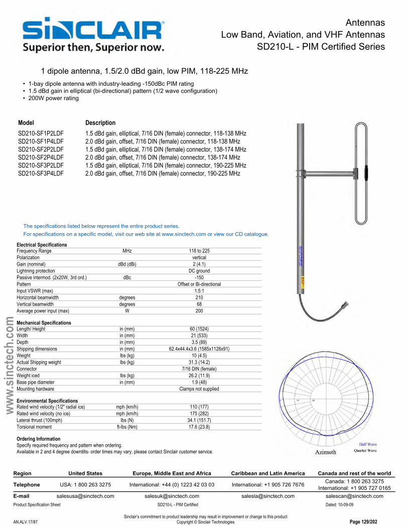
SD210-L - PIM Certified Series
1 dipole antenna, 1.5/2.0 dBd gain, low PIM, 118-225 MHz• 1-bay dipole antenna with industry-leading -150dBc PIM rating• 1.5 dBd gain in elliptical (bi-directional) pattern (1/2 wave configuration)• 200W power rating
Model DescriptionSD210-SF1P2LDF 1.5 dBd gain, elliptical, 7/16 DIN (female) connector, 118-138 MHzSD210-SF1P4LDF 2.0 dBd gain, offset, 7/16 DIN (female) connector, 118-138 MHzSD210-SF2P2LDF 1.5 dBd gain, elliptical, 7/16 DIN (female) connector, 138-174 MHzSD210-SF2P4LDF 2.0 dBd gain, offset, 7/16 DIN (female) connector, 138-174 MHzSD210-SF3P2LDF 1.5 dBd gain, elliptical, 7/16 DIN (female) connector, 190-225 MHzSD210-SF3P4LDF 2.0 dBd gain, offset, 7/16 DIN (female) connector, 190-225 MHz
The specifications listed below represent the entire product series.For specifications on a specific model, visit our web site at www.sinctech.com or view our CD catalogue.
Electrical SpecificationsFrequency Range MHz 118 to 225Polarization verticalGain (nominal) dBd (dBi) 2 (4.1)Lightning protection DC groundPassive intermod. (2x20W, 3rd ord.) dBc -150Pattern Offset or Bi-directionalInput VSWR (max) 1.5:1Horizontal beamwidth degrees 210Vertical beamwidth degrees 68Average power input (max) W 200
Mechanical SpecificationsLength/ Height in (mm) 60 (1524)Width in (mm) 21 (533)Depth in (mm) 3.5 (89)Shipping dimensions in (mm) 62.4x44.4x3.6 (1585x1128x91)Weight lbs (kg) 10 (4.5)Actual Shipping weight lbs (kg) 31.3 (14.2)Connector 7/16 DIN (female)Weight iced lbs (kg) 26.2 (11.9)Base pipe diameter in (mm) 1.9 (48)Mounting hardware Clamps not supplied
Environmental SpecificationsRated wind velocity (1/2" radial ice) mph (km/h) 110 (177)Rated wind velocity (no ice) mph (km/h) 175 (282)Lateral thrust (100mph) lbs (N) 34.1 (151.7)Torsional moment ft-lbs (Nm) 17.6 (23.8)
Ordering InformationSpecify required frequency and pattern when ordering.Available in 2 and 4 degree downtilts- order times may vary, please contact Sinclair customer service.
Region United States Europe, Middle East and Africa Caribbean and Latin America Canada and rest of the world
Telephone USA: 1 800 263 3275 International: +44 (0) 1223 42 03 03 International: +1 905 726 7676 Canada: 1 800 263 3275International: +1 905 727 0165
E-mail [email protected] [email protected] [email protected] [email protected] Specification Sheet SD210-L - PIM Certified Dated: 10-09-09
Sinclair’s commitment to product leadership may result in improvement or change to this productCopyright © Sinclair TechnologiesAN.ALV.17/87 Page 129/202
www.
sinct
ech.
com

AntennasLow Band, Aviation, and VHF Antennas
SD212 Series
2 dipole antenna, 5.0/5.5 dBd gain, 118-225 MHz• Covers 118-225 MHz in 3 band splits• 5.0 dBd gain at elliptical (bi-directional) pattern (1/2 wave), 5.5 dBd gain at offset pattern (1/4 wave)• 250W power handling• Recommend using an SMK-125-A3 side mounting kit
1/4 wave shown
Model DescriptionSD212-SF1P2SNM 5.0 dBd gain, elliptical, N (male) connector, 118-138 MHzSD212-SF1P4SNM 5.5 dBd gain, offset, N (male) connector, 118-138 MHzSD212-SF2P2SNM 5.0 dBd gain, elliptical, N (male) connector, 138-174 MHzSD212-SF2P4SNM 5.5 dBd gain, offset, N (male) connector, 138-174 MHzSD212-SF2PASNM 5.0/5.5 dBd gain, field adjustable, N (male) connector, 138-174 MHzSD212-SF3P2SNM(D00B) 5.0 dBd gain, elliptical, N (male) connector, 216-225 MHzSD212-SF3P4SNM(D00B) 5.5 dBd gain, elliptical, N (male) connector, 216-225 MHz
The specifications listed below represent the entire product series.For specifications on a specific model, visit our web site at www.sinctech.com or view our CD catalogue.
Electrical SpecificationsPolarization verticalLightning protection DC groundPattern Offset or Bi-directionalInput VSWR (max) 1.5:1Horizontal beamwidth degrees 210Vertical beamwidth degrees 34Average power input (max) W 300
Mechanical SpecificationsLength/ Height in (mm) 120 (3048)Width in (mm) 23 (584)Depth in (mm) 3 (76)Shipping dimensions in (mm) 124x4x44 (3150x102x1118)Weight lbs (kg) 16 (7.3)Actual Shipping weight lbs (kg) 40 (18.2)Connector N (male)Base pipe diameter in (mm) 1.9 (48)Base pipe mounting length in (mm) 36 (914)Mounting hardware clamps not supplied
Environmental SpecificationsRated wind velocity (1/2" radial ice) mph (km/h) 105 (169)Rated wind velocity (no ice) mph (km/h) 140 (225)Tip deflection degrees 5.3Projected area (Flat Plate Equivalent) ft² (m²) 2.1 (0.2)Projected area (ice) ft² (m²) 3.71 (0.34)Lateral thrust (100mph) lbs (N) 77 (342.5)Torsional moment ft-lbs (Nm) 83 (112.1)
Ordering InformationSpecify required frequency, pattern and connector option when ordering.2 x #130 clamps recommended (not included).Recommend using an SMK-125-A3 side mounting kit
Region United States Europe, Middle East and Africa Caribbean and Latin America Canada and rest of the world
Telephone USA: 1 800 263 3275 International: +44 (0) 1223 42 03 03 International: +1 905 726 7676 Canada: 1 800 263 3275International: +1 905 727 0165
E-mail [email protected] [email protected] [email protected] [email protected] Specification Sheet SD212 Dated: 10-09-09
Sinclair’s commitment to product leadership may result in improvement or change to this productCopyright © Sinclair TechnologiesAN.ALV.18/87 Page 130/202
www.
sinct
ech.
com

AntennasLow Band, Aviation, and VHF Antennas
SD212-H Series
2 dipole antenna, 5.0/5.5 dBd gain, HD, 118-225 MHz• Covers 118-225 MHz in 3 band splits• 5.0 dBd gain at elliptical (bi-directional) pattern (1/2 wave), 5.5 dBd gain at offset pattern (1/4 wave)• 300W power handling
Model DescriptionSD212-HF2P2SNM(D00B) 5.0 dBd gain, N (male) connector, 138-174 MHzSD212-HF2P4SNM(D00B) 5.5 dBd gain, N (male) connector, 138-174 MHz
The specifications listed below represent the entire product series.For specifications on a specific model, visit our web site at www.sinctech.com or view our CD catalogue.
Electrical SpecificationsBandwidth MHz 36Frequency Range MHz 118 to 225Polarization verticalGain (nominal) dBd (dBi) 5.5 (7.6)Electrical tilt (available) 0, 2, 4Lightning protection DC groundPattern Offset or Bi-directionalInput VSWR (max) 1.5:1Horizontal beamwidth degrees 210Vertical beamwidth degrees 34Average power input (max) W 300
Mechanical SpecificationsLength/ Height in (mm) 120 (3048)Width in (mm) 42.6 (1082)Depth in (mm) 4 (102)Shipping dimensions in (mm) 125x46x4.5 (3175x1168x114)Weight lbs (kg) 41 (18.6)Actual Shipping weight lbs (kg) 68 (30.9)Connector N (male)Base pipe diameter in (mm) 2.9 (74)Mounting hardware clamps not supplied
Environmental SpecificationsRated wind velocity (1/2" radial ice) mph (km/h) 105 (169)Rated wind velocity (no ice) mph (km/h) 156 (251)Projected area (Flat Plate Equivalent) ft² (m²) 2.8 (0.26)Projected area (ice) ft² (m²) 7.5 (0.7)
Ordering InformationSpecify required frequency and pattern when ordering.Available in 2 and 4 degree downtilts- order times may vary, please contact Sinclair customer service
Region United States Europe, Middle East and Africa Caribbean and Latin America Canada and rest of the world
Telephone USA: 1 800 263 3275 International: +44 (0) 1223 42 03 03 International: +1 905 726 7676 Canada: 1 800 263 3275International: +1 905 727 0165
E-mail [email protected] [email protected] [email protected] [email protected] Specification Sheet SD212-H Dated: 10-09-09
Sinclair’s commitment to product leadership may result in improvement or change to this productCopyright © Sinclair TechnologiesAN.ALV.19/87 Page 131/202
www.
sinct
ech.
com

AntennasLow Band, Aviation, and VHF Antennas
SD212-HL - PIM Certified Series
2 dipole antenna, 4.5/5.0 dBd gain, low PIM, HD, 118-225 MHz• Industry-leading -150 dBc PIM rating, covers 118-225 MHz in 3 band splits• 4.5 dBd gain at elliptical (bi-directional) pattern (1/2 wave), 5.0 dBd gain at offset pattern (1/4 wave)• 300W power handling
Standard SD212-L model shown.
Model DescriptionSD212-HF1P2LDF 4.5 dBd gain, elliptical, 7/16 DIN (female) connector, 118-138 MHzSD212-HF1P4LDF 5.0 dBd gain, offset, 7/16 DIN (female) connector, 118-138 MHzSD212-HF2P2LDF(D00B) 4.5 dBd gain, elliptical, 7/16 DIN (female) connector, 138-174 MHzSD212-HF2P2LNM(D00B) 4.5 dBd gain, elliptical, N (male) connector, 138-174 MHzSD212-HF2P4LDF(D00B) 5.0 dBd gain, offset, HD, 7/16 DIN (female) connector, 138-174 MHzSD212-HF3P2LDF 4.5 dBd gain, elliptical, 7/16 DIN (female) connector, 190-225 MHzSD212-HF3P4LDF 5.0 dBd gain, offset, 7/16 DIN (female) connector, 190-225 MHz
The specifications listed below represent the entire product series.For specifications on a specific model, visit our web site at www.sinctech.com or view our CD catalogue.
Electrical SpecificationsFrequency Range MHz 118 to 225Polarization verticalGain (nominal) dBd (dBi) 5 (7.1)Lightning protection DC groundPassive intermod. (2x20W, 3rd ord.) dBc -150Pattern Offset or Bi-directionalInput VSWR (max) 1.5:1Horizontal beamwidth degrees 210Vertical beamwidth degrees 36Average power input (max) W 200
Mechanical SpecificationsLength/ Height in (mm) 120 (3048)Width in (mm) 27.3 (694)Depth in (mm) 5.8 (148)Weight lbs (kg) 41 (18.6)Actual Shipping weight lbs (kg) 208 (94.4)Connector 7/16 DIN (female)Base pipe diameter in (mm) 4 (102)Mounting hardware Clamps not supplied
Environmental SpecificationsRated wind velocity (1/2" radial ice) mph (km/h) 105 (169)Rated wind velocity (no ice) mph (km/h) 156 (251)Projected area (Flat Plate Equivalent) ft² (m²) 1 (0.09)Projected area (ice) ft² (m²) 2.37 (0.22)Lateral thrust (100mph) lbs (N) 253 (1125.3)Torsional moment ft-lbs (Nm) 78 (105.3)
Ordering InformationSpecify required frequency and pattern when ordering.
Region United States Europe, Middle East and Africa Caribbean and Latin America Canada and rest of the world
Telephone USA: 1 800 263 3275 International: +44 (0) 1223 42 03 03 International: +1 905 726 7676 Canada: 1 800 263 3275International: +1 905 727 0165
E-mail [email protected] [email protected] [email protected] [email protected] Specification Sheet SD212-HL - PIM Certified Dated: 10-09-09
Sinclair’s commitment to product leadership may result in improvement or change to this productCopyright © Sinclair TechnologiesAN.ALV.20/87 Page 132/202
www.
sinct
ech.
com
AntennasLow Band, Aviation, and VHF Antennas
SD212-L - PIM Certified Series
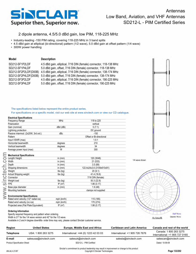
2 dipole antenna, 4.5/5.0 dBd gain, low PIM, 118-225 MHz• Industry-leading -150 PIM rating, covering 118-225 MHz in 3 band splits• 4.5 dBd gain at elliptical (bi-directional) pattern (1/2 wave), 5.0 dBd gain at offset pattern (1/4 wave)• 300W power handling
1/4 wave shown
Model DescriptionSD212-SF1P2LDF 4.5 dBd gain, elliptical, 7/16 DIN (female) connector, 118-138 MHzSD212-SF1P4LDF 5.0 dBd gain, offset, 7/16 DIN (female) connector, 118-138 MHzSD212-SF2P2LDF(D00B) 4.5 dBd gain, elliptical, 7/16 DIN (female) connector, 138-174 MHzSD212-SF2P4LDF(D00B) 5.0 dBd gain, offset, 7/16 DIN (female) connector, 138-174 MHzSD212-SF3P2LDF 4.5 dBd gain, elliptical, 7/16 DIN (female) connector, 190-225 MHzSD212-SF3P4LDF 5.0 dBd gain, offset, 7/16 DIN (female) connector, 190-225 MHz
The specifications listed below represent the entire product series.For specifications on a specific model, visit our web site at www.sinctech.com or view our CD catalogue.
Electrical SpecificationsFrequency Range MHz 118 to 225Polarization verticalGain (nominal) dBd (dBi) 5 (7.1)Lightning protection DC groundPassive intermod. (2x20W, 3rd ord.) dBc -150Pattern Offset or Bi-directionalInput VSWR (max) 1.5:1Horizontal beamwidth degrees 210Vertical beamwidth degrees 34Average power input (max) W 300
Mechanical SpecificationsLength/ Height in (mm) 120 (3048)Width in (mm) 21 (533)Depth in (mm) 3.5 (89)Shipping dimensions in (mm) 122.4x24x3.6 (3109x610x91)Weight lbs (kg) 20 (9.1)Actual Shipping weight lbs (kg) 41.4 (18.8)Connector 7/16 DIN (female)Weight iced lbs (kg) 50.3 (22.8)FPE ft² (m²) 1.86 (0.17)Base pipe diameter in (mm) 1.9 (48)Mounting hardware clamps not supplied
Environmental SpecificationsRated wind velocity (1/2" radial ice) mph (km/h) 115 (185)Rated wind velocity (no ice) mph (km/h) 170 (274)Projected area (Flat Plate Equivalent) ft² (m²) 1.86 (0.17)
Ordering InformationSpecify required frequency and pattern when ordering.Width is 21" for the 1/4 wave version and 42" for the 1/2 wave.Available in 2 and 4 degree downtilts- order time may vary, please contact Sinclair customer service.
Region United States Europe, Middle East and Africa Caribbean and Latin America Canada and rest of the world
Telephone USA: 1 800 263 3275 International: +44 (0) 1223 42 03 03 International: +1 905 726 7676 Canada: 1 800 263 3275International: +1 905 727 0165
E-mail [email protected] [email protected] [email protected] [email protected] Specification Sheet SD212-L - PIM Certified Dated: 10-09-09
Sinclair’s commitment to product leadership may result in improvement or change to this productCopyright © Sinclair TechnologiesAN.ALV.21/87 Page 133/202
www.
sinct
ech.
com
AntennasLow Band, Aviation, and VHF Antennas
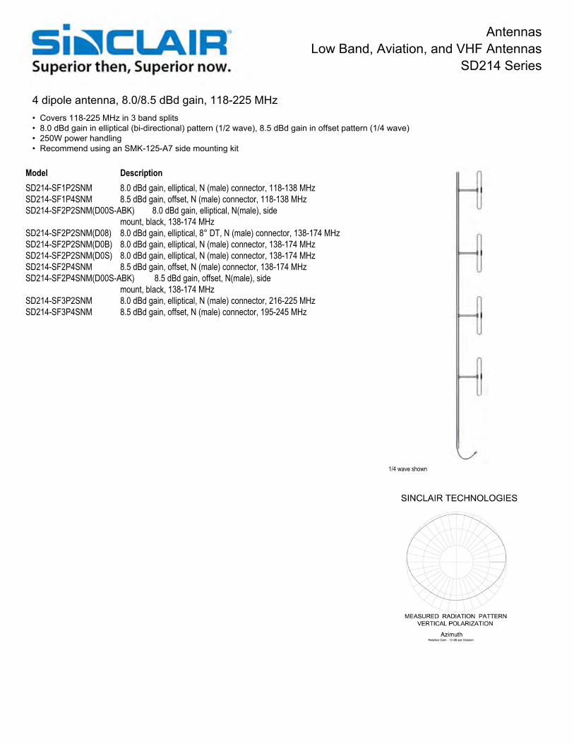
SD214 Series
4 dipole antenna, 8.0/8.5 dBd gain, 118-225 MHz• Covers 118-225 MHz in 3 band splits• 8.0 dBd gain in elliptical (bi-directional) pattern (1/2 wave), 8.5 dBd gain in offset pattern (1/4 wave)• 250W power handling• Recommend using an SMK-125-A7 side mounting kit
1/4 wave shown
Model DescriptionSD214-SF1P2SNM 8.0 dBd gain, elliptical, N (male) connector, 118-138 MHzSD214-SF1P4SNM 8.5 dBd gain, offset, N (male) connector, 118-138 MHzSD214-SF2P2SNM(D00S-ABK) 8.0 dBd gain, elliptical, N(male), side
mount, black, 138-174 MHzSD214-SF2P2SNM(D08) 8.0 dBd gain, elliptical, 8° DT, N (male) connector, 138-174 MHzSD214-SF2P2SNM(D0B) 8.0 dBd gain, elliptical, N (male) connector, 138-174 MHzSD214-SF2P2SNM(D0S) 8.0 dBd gain, elliptical, N (male) connector, 138-174 MHzSD214-SF2P4SNM 8.5 dBd gain, offset, N (male) connector, 138-174 MHzSD214-SF2P4SNM(D00S-ABK) 8.5 dBd gain, offset, N(male), side
mount, black, 138-174 MHzSD214-SF3P2SNM 8.0 dBd gain, elliptical, N (male) connector, 216-225 MHzSD214-SF3P4SNM 8.5 dBd gain, offset, N (male) connector, 195-245 MHz

AntennasLow Band, Aviation, and VHF Antennas
SD214 Series
Region United States Europe, Middle East and Africa Caribbean and Latin America Canada and rest of the world
Telephone USA: 1 800 263 3275 International: +44 (0) 1223 42 03 03 International: +1 905 726 7676 Canada: 1 800 263 3275International: +1 905 727 0165
E-mail [email protected] [email protected] [email protected] [email protected] Specification Sheet SD214 Dated: 10-09-09
Sinclair’s commitment to product leadership may result in improvement or change to this productCopyright © Sinclair TechnologiesAN.ALV.23/87 Page 135/202
www.
sinct
ech.
com
The specifications listed below represent the entire product series.For specifications on a specific model, visit our web site at www.sinctech.com or view our CD catalogue.
Electrical SpecificationsFrequency Range MHz 118 to 225Polarization verticalGain (nominal) dBd (dBi) 8.5 (10.6)Lightning protection DC groundPattern Offset or Bi-directionalInput VSWR (max) 1.5:1Horizontal beamwidth degrees 210Vertical beamwidth degrees 17Average power input (max) W 300
Mechanical SpecificationsLength/ Height in (mm) 240 (6096)Width in (mm) 23 (584)Depth in (mm) 4 (102)Shipping dimensions in (mm) 247x44x6 (6274x1118x152)Weight lbs (kg) 45.5 (20.7)Actual Shipping weight lbs (kg) 125 (56.8)Connector N (male)Base pipe diameter in (mm) 2.4 (60)Base pipe mounting length in (mm) 72 (1829)Mounting hardware clamps not supplied
Environmental SpecificationsRated wind velocity (1/2" radial ice) mph (km/h) 90 (145)Rated wind velocity (no ice) mph (km/h) 130 (209)Projected area (Flat Plate Equivalent) ft² (m²) 4.51 (0.42)Projected area (ice) ft² (m²) 7.51 (0.7)Lateral thrust (100mph) lbs (N) 152 (676.1)
Ordering InformationRecommend using an SMK-125-A7 side mounting kit
Region United States Europe, Middle East and Africa Caribbean and Latin America Canada and rest of the world
Telephone USA: 1 800 263 3275 International: +44 (0) 1223 42 03 03 International: +1 905 726 7676 Canada: 1 800 263 3275International: +1 905 727 0165
E-mail [email protected] [email protected] [email protected] [email protected] Specification Sheet SD214 Dated: 10-09-09
Sinclair’s commitment to product leadership may result in improvement or change to this productCopyright © Sinclair TechnologiesAN.ALV.23/87 Page 135/202
www.
sinct
ech.
com

AntennasLow Band, Aviation, and VHF Antennas
SD214-HL - PIM Certified Series
4 dipole antenna, 7.0/7.5 dBd gain, low PIM, HD, 118-225 MHz• Industry-leading -150dBc PIM rating, covering 118-225 MHz in 3 band splits• 7.0 dBd gain in bi-directional pattern (1/2 wave), and 7.5 dBd gain in the offset pattern (1/4 wave)• Heavy duty version with 300W power handling
Standard SD214-L model shown.
Model DescriptionSD214-HF1P2LDF 7.0 dBd gain, elliptical, 7/16 DIN (female) connector, 118-138 MHzSD214-HF1P4LDF 7.5 dBd gain, offset, 7/16 DIN (female) connector, 118-138 MHzSD214-HF2P2LDF 7.0 dBd gain, elliptical, 7/16 DIN (female) connector, 138-174 MHzSD214-HF2P3LDF(D00S-LSABK) 7.2 dBd gain, bidirectional, 7/16 connector,
lightning spike, black, 138-174 MHzSD214-HF2P4LDF 7.5 dBd gain, offset, 7/16 DIN (female) connector, 138-174 MHzSD214-HF2P4LDF(D00S-LSABK) 7.5 dBd gain, offset, 7/16 DIN (female),
lightning spike, black, 138-174 MHzSD214-HF3P2LDF 7.0 dBd gain, elliptical, 7/16 DIN (female) connector, 190-225 MHzSD214-HF3P4LDF 7.5 dBd gain, offset, 7/16 DIN (female) connector, 190-225 MHz
The specifications listed below represent the entire product series.For specifications on a specific model, visit our web site at www.sinctech.com or view our CD catalogue.
Electrical SpecificationsFrequency Range MHz 118 to 225Polarization verticalGain (nominal) dBd (dBi) 7 (9.1)Lightning protection DC groundPassive intermod. (2x20W, 3rd ord.) dBc -150Pattern Offset or Bi-directionalInput VSWR (max) 1.5:1Vertical beamwidth degrees 18Average power input (max) W 300
Mechanical SpecificationsLength/ Height in (mm) 240 (6096)Width in (mm) 25.8 (655)Depth in (mm) 5.8 (147)Shipping dimensions in (mm) 247x44x6 (6274x1118x152)Weight lbs (kg) 95 (43.1)Actual Shipping weight lbs (kg) 150 (68.1)Connector 7/16 DIN (female)Weight iced lbs (kg) 291 (132.1)Base pipe diameter in (mm) 4 (102)Mounting hardware Clamps not supplied
Environmental SpecificationsRated wind velocity (1/2" radial ice) mph (km/h) 115 (185)Rated wind velocity (no ice) mph (km/h) 175 (282)Projected area (Flat Plate Equivalent) ft² (m²) 5.57 (0.52)Projected area (ice) ft² (m²) 17.04 (1.58)Lateral thrust (100mph) lbs (N) 214 (951.9)
Ordering InformationSpecify required frequency and pattern when ordering.
Region United States Europe, Middle East and Africa Caribbean and Latin America Canada and rest of the world
Telephone USA: 1 800 263 3275 International: +44 (0) 1223 42 03 03 International: +1 905 726 7676 Canada: 1 800 263 3275International: +1 905 727 0165
E-mail [email protected] [email protected] [email protected] [email protected] Specification Sheet SD214-HL - PIM Certified Dated: 10-09-09
Sinclair’s commitment to product leadership may result in improvement or change to this productCopyright © Sinclair TechnologiesAN.ALV.24/87 Page 136/202
www.
sinct
ech.
com

AntennasLow Band, Aviation, and VHF Antennas
SD214-L - PIM Certified Series
4 dipole antenna, 7.0/7.5 dBd gain, low PIM, 118-225 MHz• Industry-leading -150 dBc PIM rating, covering 118-225 MHz in 3 band splits• 7.0 dBd gain in elliptical (bi-directional) pattern (1/2 wave), 7.5 dBd gain in offset pattern (1/4 wave)• 300W power handling
1/4 wave shown
Model DescriptionSD214-SF1P2LDF 7.0 dBd gain, elliptical, 7/16 DIN (female) connector, 118-138 MHzSD214-SF1P4LDF 7.5 dBd gain, offset, 7/16 DIN (female) connector, 118-138 MHzSD214-SF2P2LDF 7.0 dBd gain, elliptical, 7/16 DIN (female) connector, 138-174 MHzSD214-SF2P4LDF 7.5 dBd gain, offset, 7/16 DIN (female) connector, 138-174 MHzSD214-SF3P2LDF 7.0 dBd gain, elliptical, 7/16 DIN (female) connector, 190-225 MHzSD214-SF3P4LDF 7.5 dBd gain, offset, 7/16 DIN (female) connector, 190-225 MHz
The specifications listed below represent the entire product series.For specifications on a specific model, visit our web site at www.sinctech.com or view our CD catalogue.
Electrical SpecificationsBandwidth MHz 36Frequency Range MHz 118 to 225Polarization verticalGain (nominal) dBd (dBi) 7.5 (9.6)Electrical tilt (available) 0, 2 or 4Lightning protection DC groundPassive intermod. (2x20W, 3rd ord.) dBc -150Pattern Offset or Bi-directionalInput VSWR (max) 1.5:1Horizontal beamwidth degrees 210Vertical beamwidth degrees 18Average power input (max) W 300
Mechanical SpecificationsLength/ Height in (mm) 240 (6096)Width in (mm) 42 (1067)Depth in (mm) 3.5 (89)Shipping dimensions in (mm) 247x44x6.5 (6274x1118x165)Weight lbs (kg) 63.4 (28.8)Actual Shipping weight lbs (kg) 85 (38.6)Connector 7/16 DIN (female)Weight iced lbs (kg) 137.3 (62.3)FPE ft² (m²) 4.25 (0.39)Base pipe diameter in (mm) 2.4 (60)Mounting hardware clamps not supplied
Environmental SpecificationsRated wind velocity (1/2" radial ice) mph (km/h) 90 (145)
Ordering InformationSpecify required frequency and pattern when ordering.2 x #130 clamps recommended (not included).2 and 4 degree downtilts available- order times may vary, please contact Sinclair customer service.
Region United States Europe, Middle East and Africa Caribbean and Latin America Canada and rest of the world
Telephone USA: 1 800 263 3275 International: +44 (0) 1223 42 03 03 International: +1 905 726 7676 Canada: 1 800 263 3275International: +1 905 727 0165
E-mail [email protected] [email protected] [email protected] [email protected] Specification Sheet SD214-L - PIM Certified Dated: 10-09-09
Sinclair’s commitment to product leadership may result in improvement or change to this productCopyright © Sinclair TechnologiesAN.ALV.25/87 Page 137/202
www.
sinct
ech.
com

AntennasLow Band, Aviation, and VHF Antennas
SD218 Series
8 dipole antenna, 11.0/11.5 dBd gain, 118-225 MHz• 11 dBd gain in elliptical (bi-directional) pattern (1/2 wave), 11.5 dBd gain in offset pattern (1/4 wave)• 118-225 MHz at a VSWR of 1.5:1 or better
1/2 wave shown
Model DescriptionSD218-SF1P2SNM 11 dBd gain, elliptical, N (male) connector, 118-138 MHzSD218-SF1P4SNM 11.5 dBd gain, offset, N (male) connector, 118-138 MHzSD218-SF2P2SNM 11 dBd gain, elliptical, N (male) connector, 138-174 MHzSD218-SF2P4SNM 11.5 dBd gain, offset, N (male) connector, 138-174 MHz
The specifications listed below represent the entire product series.For specifications on a specific model, visit our web site at www.sinctech.com or view our CD catalogue.
Electrical SpecificationsFrequency Range MHz 118 to 225Polarization verticalGain (nominal) dBd (dBi) 11.5 (13.6)Lightning protection DC groundPattern Offset or Bi-directionalInput VSWR (max) 1.5:1Horizontal beamwidth degrees 210Vertical beamwidth degrees 8Average power input (max) W 300
Mechanical SpecificationsLength/ Height in (mm) 480 (12192)Width in (mm) 23 (584)Depth in (mm) 4 (102)Shipping dimensions in (mm) 300x24x7.2 (7620x610x183)Weight lbs (kg) 91 (41.3)Actual Shipping weight lbs (kg) 200 (90.8)Connector N (male)Base pipe diameter in (mm) 2.4 (60)Base pipe mounting length in (mm) 72 (1829)Mounting hardware clamps not supplied
Environmental SpecificationsRated wind velocity (1/2" radial ice) mph (km/h) 90 (145)Rated wind velocity (no ice) mph (km/h) 130 (209)Projected area (Flat Plate Equivalent) ft² (m²) 8 (0.74)Projected area (ice) ft² (m²) 13.7 (1.27)Lateral thrust (100mph) lbs (N) 304 (1352.2)
Ordering InformationSpecify frequency band of operation and connector.Clamps not included.
Region United States Europe, Middle East and Africa Caribbean and Latin America Canada and rest of the world
Telephone USA: 1 800 263 3275 International: +44 (0) 1223 42 03 03 International: +1 905 726 7676 Canada: 1 800 263 3275International: +1 905 727 0165
E-mail [email protected] [email protected] [email protected] [email protected] Specification Sheet SD218 Dated: 10-09-09
Sinclair’s commitment to product leadership may result in improvement or change to this productCopyright © Sinclair TechnologiesAN.ALV.26/87 Page 138/202
www.
sinct
ech.
com

AntennasLow Band, Aviation, and VHF Antennas
SD218-L - PIM Certified Series
8 dipole antenna, 9.5/10 dBd gain, low PIM, 118-225 MHz• 9.5 dBd gain in elliptical (bi-directional) pattern (1/2 wave), 10 dBd gain in offset pattern (1/4 wave)• Low PIM rating at -150dBc
1/2 wave shown
Model DescriptionSD218-SF1P2LDF 9.5 dBd gain, elliptical, N (male) connector, 118-138 MHzSD218-SF1P4LDF 10 dBd gain, offset, N (male) connector, 118-138 MHzSD218-SF2P2LDF 9.5 dBd gain, elliptical, 138-174 MHzSD218-SF2P4LDF 10 dBd gain, offset, 138-174 MHz
The specifications listed below represent the entire product series.For specifications on a specific model, visit our web site at www.sinctech.com or view our CD catalogue.
Electrical SpecificationsBandwidth MHz 36Frequency Range MHz 118 to 225Polarization verticalGain (nominal) dBd (dBi) 10 (12.1)Lightning protection DC groundPassive intermod. (2x20W, 3rd ord.) dBc -150Pattern Offset or Bi-directionalInput VSWR (max) 1.5:1Vertical beamwidth degrees 9Average power input (max) W 300
Mechanical SpecificationsLength/ Height in (mm) 404 (10262)Width in (mm) 26 (660)Depth in (mm) 2.9 (74)Shipping dimensions in (mm) 300x24x7.2 (7620x610x183)Weight lbs (kg) 90 (40.9)Actual Shipping weight lbs (kg) 200 (90.8)Connector N (male)FPE ft² (m²) 8.4 (0.78)Base pipe diameter in (mm) 2.4 (60)Base pipe mounting length in (mm) 72 (1829)Mounting hardware clamps not supplied
Environmental SpecificationsRated wind velocity (1/2" radial ice) mph (km/h) 115 (185)Rated wind velocity (no ice) mph (km/h) 170 (274)Projected area (Flat Plate Equivalent) ft² (m²) 8 (0.74)
Ordering InformationSpecify frequency band of operation and pattern.Clamps not included. Recommend qty 2- Clamp#130
Region United States Europe, Middle East and Africa Caribbean and Latin America Canada and rest of the world
Telephone USA: 1 800 263 3275 International: +44 (0) 1223 42 03 03 International: +1 905 726 7676 Canada: 1 800 263 3275International: +1 905 727 0165
E-mail [email protected] [email protected] [email protected] [email protected] Specification Sheet SD218-L - PIM Certified Dated: 10-09-09
Sinclair’s commitment to product leadership may result in improvement or change to this productCopyright © Sinclair TechnologiesAN.ALV.27/87 Page 139/202
www.
sinct
ech.
com
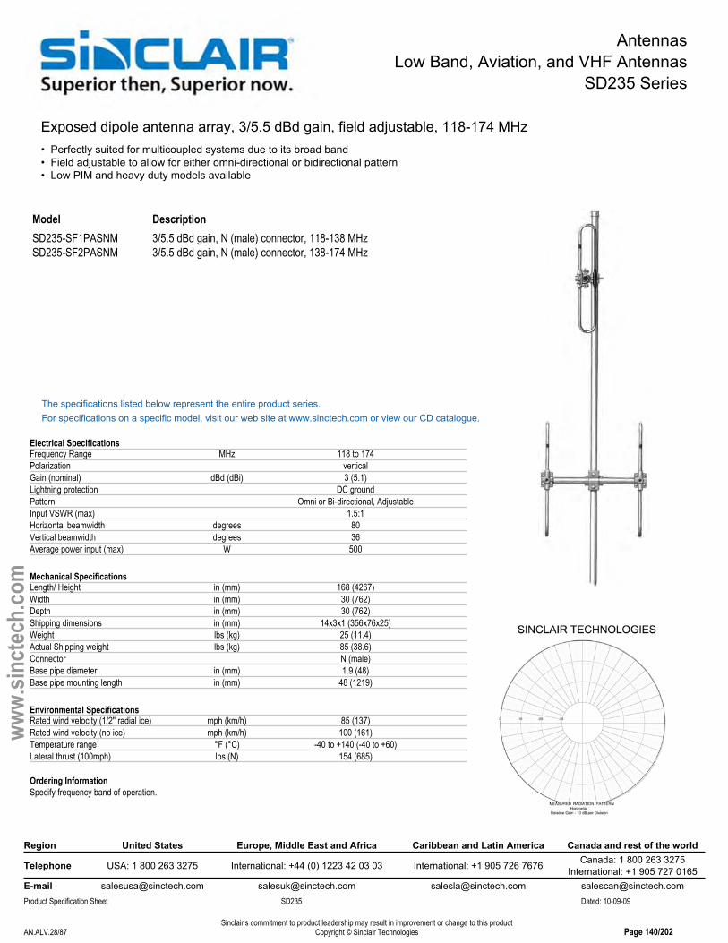
AntennasLow Band, Aviation, and VHF Antennas
SD235 Series
Exposed dipole antenna array, 3/5.5 dBd gain, field adjustable, 118-174 MHz• Perfectly suited for multicoupled systems due to its broad band• Field adjustable to allow for either omni-directional or bidirectional pattern• Low PIM and heavy duty models available
Model DescriptionSD235-SF1PASNM 3/5.5 dBd gain, N (male) connector, 118-138 MHzSD235-SF2PASNM 3/5.5 dBd gain, N (male) connector, 138-174 MHz
The specifications listed below represent the entire product series.For specifications on a specific model, visit our web site at www.sinctech.com or view our CD catalogue.
Electrical SpecificationsFrequency Range MHz 118 to 174Polarization verticalGain (nominal) dBd (dBi) 3 (5.1)Lightning protection DC groundPattern Omni or Bi-directional, AdjustableInput VSWR (max) 1.5:1Horizontal beamwidth degrees 80Vertical beamwidth degrees 36Average power input (max) W 500
Mechanical SpecificationsLength/ Height in (mm) 168 (4267)Width in (mm) 30 (762)Depth in (mm) 30 (762)Shipping dimensions in (mm) 14x3x1 (356x76x25)Weight lbs (kg) 25 (11.4)Actual Shipping weight lbs (kg) 85 (38.6)Connector N (male)Base pipe diameter in (mm) 1.9 (48)Base pipe mounting length in (mm) 48 (1219)
Environmental SpecificationsRated wind velocity (1/2" radial ice) mph (km/h) 85 (137)Rated wind velocity (no ice) mph (km/h) 100 (161)Temperature range °F (°C) -40 to +140 (-40 to +60)Lateral thrust (100mph) lbs (N) 154 (685)
Ordering InformationSpecify frequency band of operation.
Region United States Europe, Middle East and Africa Caribbean and Latin America Canada and rest of the world
Telephone USA: 1 800 263 3275 International: +44 (0) 1223 42 03 03 International: +1 905 726 7676 Canada: 1 800 263 3275International: +1 905 727 0165
E-mail [email protected] [email protected] [email protected] [email protected] Specification Sheet SD235 Dated: 10-09-09
Sinclair’s commitment to product leadership may result in improvement or change to this productCopyright © Sinclair TechnologiesAN.ALV.28/87 Page 140/202
www.
sinct
ech.
com

AntennasLow Band, Aviation, and VHF Antennas
SD2352 Series
Exposed dipole antenna array, 6/8.5 dBd gain, field adjustable, 118-174 MHz• Perfectly suited for multicoupled systems due to its broad band operation• Higher gain achieved with double array• Site specific hardware needed for this antenna
Model DescriptionSD2352-HF2PASDF(D00B-LSABK) 6/8.5 dBd gain, 7/16 DIN (female), HD,
lightning spike, black, 138-174 MHzSD2352-SF2PASNM 6/8.5 dBd gain, field adjustable, N (male) connector, 138-174 MHz
The specifications listed below represent the entire product series.For specifications on a specific model, visit our web site at www.sinctech.com or view our CD catalogue.
Electrical SpecificationsFrequency Range MHz 118 to 174Polarization verticalLightning protection DC groundPattern Omni or Bi-directional, AdjustableInput VSWR (max) 1.5:1Horizontal beamwidth degrees 80Vertical beamwidth degrees 16Average power input (max) W 300
Mechanical SpecificationsLength/ Height in (mm) 240 (6096)Width in (mm) 30 (762)Depth in (mm) 30 (762)Shipping dimensions in (mm) 20.2x3.6x1 (513x91x25)Weight lbs (kg) 76 (34.5)Actual Shipping weight lbs (kg) 165 (74.9)Connector N (male)Base pipe diameter in (mm) 2.9 (73)Base pipe mounting length in (mm) 60 (1524)
Environmental SpecificationsRated wind velocity (1/2" radial ice) mph (km/h) 85 (137)Rated wind velocity (no ice) mph (km/h) 100 (161)Projected area (Flat Plate Equivalent) ft² (m²) 5.6 (0.52)Projected area (ice) ft² (m²) 9.59 (0.89)Lateral thrust (100mph) lbs (N) 303 (1347.7)Bending moment ft-lbs (Nm) 2307 (3114.5)
Ordering InformationSpecify frequency band of operation.Clamps not included.
Region United States Europe, Middle East and Africa Caribbean and Latin America Canada and rest of the world
Telephone USA: 1 800 263 3275 International: +44 (0) 1223 42 03 03 International: +1 905 726 7676 Canada: 1 800 263 3275International: +1 905 727 0165
E-mail [email protected] [email protected] [email protected] [email protected] Specification Sheet SD2352 Dated: 10-09-09
Sinclair’s commitment to product leadership may result in improvement or change to this productCopyright © Sinclair TechnologiesAN.ALV.29/87 Page 141/202
www.
sinct
ech.
com

AntennasLow Band, Aviation, and VHF Antennas
SD235D Series
Exposed dipole array, 3/5.5 dBd gain, dual, 108-174 MHz• A dual antenna perfectly suited for multicoupled systems due to its broad band• Omni-directional or bi-directional pattern easily changed in the field• Low PIM and heavy duty models available
Model DescriptionSD235D-SF2PASNM 3/5.5 dBd gain, Dual, N (male) connector, 138-174 MHz
The specifications listed below represent the entire product series.For specifications on a specific model, visit our web site at www.sinctech.com or view our CD catalogue.
Electrical SpecificationsFrequency Range MHz 108 to 174Polarization verticalLightning protection DC groundIsolation between sections (nom) dB 30Pattern Omni or Bi-directional, AdjustableInput VSWR (max) 1.5:1Vertical beamwidth degrees 34Average power input (max) W 500
Mechanical SpecificationsLength/ Height in (mm) 240 (6096)Width in (mm) 35.5 (902)Depth in (mm) 35.5 (902)Shipping dimensions in (mm) 42x13x35 (1067x330x889)Weight lbs (kg) 90 (40.9)Actual Shipping weight lbs (kg) 165 (74.9)Connector N (male)Base pipe diameter in (mm) 2.9 (73)Mounting hardware clamps not supplied
Environmental SpecificationsRated wind velocity (1/2" radial ice) mph (km/h) 95 (153)Rated wind velocity (no ice) mph (km/h) 125 (201)Temperature range °F (°C) -40 to +140 (-40 to +60)Projected area (Flat Plate Equivalent) ft² (m²) 5.6 (0.52)Projected area (ice) ft² (m²) 9.6 (0.89)Lateral thrust (100mph) lbs (N) 235 (1045.3)Bending moment ft-lbs (Nm) 2307 (3114.5)
Ordering InformationSite specific mounting hardware is necessary with the SD235-2. Please consult Sinclair to determine suitable clamps for your application.Specify frequency band of operation.
Region United States Europe, Middle East and Africa Caribbean and Latin America Canada and rest of the world
Telephone USA: 1 800 263 3275 International: +44 (0) 1223 42 03 03 International: +1 905 726 7676 Canada: 1 800 263 3275International: +1 905 727 0165
E-mail [email protected] [email protected] [email protected] [email protected] Specification Sheet SD235D Dated: 10-09-09
Sinclair’s commitment to product leadership may result in improvement or change to this productCopyright © Sinclair TechnologiesAN.ALV.30/87 Page 142/202
www.
sinct
ech.
com
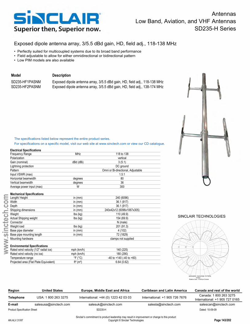
AntennasLow Band, Aviation, and VHF Antennas
SD235-H Series
Exposed dipole antenna array, 3/5.5 dBd gain, HD, field adj., 118-138 MHz• Perfectly suited for multicoupled systems due to its broad band performance• Field adjustable to allow for either omnidirectional or bidirectional pattern• Low PIM models are also available
Model DescriptionSD235-HF1PASNM Exposed dipole antenna array, 3/5.5 dBd gain, HD, field adj., 118-138 MHzSD235-HF2PASNM Exposed dipole antenna array, 3/5.5 dBd gain, HD, field adj., 138-174 MHz
The specifications listed below represent the entire product series.For specifications on a specific model, visit our web site at www.sinctech.com or view our CD catalogue.
Electrical SpecificationsFrequency Range MHz 118 to 138Polarization verticalGain (nominal) dBd (dBi) 3 (5.1)Lightning protection DC groundPattern Omni or Bi-directional, AdjustableInput VSWR (max) 1.5:1Horizontal beamwidth degrees 80Vertical beamwidth degrees 36Average power input (max) W 300
Mechanical SpecificationsLength/ Height in (mm) 240 (6096)Width in (mm) 36.1 (917)Depth in (mm) 36.1 (917)Shipping dimensions in (mm) 240x42x12 (6096x1067x305)Weight lbs (kg) 110 (49.9)Actual Shipping weight lbs (kg) 154 (69.9)Connector N (male)Weight iced lbs (kg) 201 (91.3)Base pipe diameter in (mm) 4 (102)Base pipe mounting length in (mm) 72 (1829)Mounting hardware clamps not supplied
Environmental SpecificationsRated wind velocity (1/2" radial ice) mph (km/h) 140 (225)Rated wind velocity (no ice) mph (km/h) 180 (290)Temperature range °F (°C) -40 to +140 (-40 to +60)Projected area (Flat Plate Equivalent) ft² (m²) 6.64 (0.62)
Region United States Europe, Middle East and Africa Caribbean and Latin America Canada and rest of the world
Telephone USA: 1 800 263 3275 International: +44 (0) 1223 42 03 03 International: +1 905 726 7676 Canada: 1 800 263 3275International: +1 905 727 0165
E-mail [email protected] [email protected] [email protected] [email protected] Specification Sheet SD235-H Dated: 10-09-09
Sinclair’s commitment to product leadership may result in improvement or change to this productCopyright © Sinclair TechnologiesAN.ALV.31/87 Page 143/202
www.
sinct
ech.
com

AntennasLow Band, Aviation, and VHF Antennas
SD222 Series
Exposed dipole antenna, 3/6 dBd gain, field adjustable, 132-174 MHZ• External harness allows field-adjustment for omni-directional or offset coverage• 3 dBd in omni-directional configuration, 6 dBd in offset configuration• 10 MHz bandwidth, covering 132-174 MHz band in 7 band splits
Model DescriptionSD222-SF1PASNM 3/6 dBd gain, N (male) connector, 132-142 MHzSD222-SF2PASNM 3/6 dBd gain, N (male) connector, 137-147 MHzSD222-SF3PASNM 3/6 dBd gain, N (male) connector, 142-152 MHzSD222-SF4PASNM 3/6 dBd gain, N (male) connector, 147-157 MHzSD222-SF5PASNM 3/6 dBd gain, N (male) connector, 152-162 MHzSD222-SF6PASNM 3/6 dBd gain, N (male) connector, 158-168 MHzSD222-SF7PASNM 3/6 dBd gain, N (male) connector, 164-174 MHz
The specifications listed below represent the entire product series.For specifications on a specific model, visit our web site at www.sinctech.com or view our CD catalogue.
Electrical SpecificationsBandwidth MHz 10Frequency Range MHz 132 to 174Polarization verticalLightning protection DC groundPattern Omni or Offset, AdjustableInput VSWR (max) 1.5:1Horizontal beamwidth degrees 170Vertical beamwidth degrees 34Average power input (max) W 300
Mechanical SpecificationsLength/ Height in (mm) 114 (2896)Width in (mm) 12 (305)Depth in (mm) 4 (102)Shipping dimensions in (mm) 118x5x15 (2997x127x381)Weight lbs (kg) 17 (7.7)Actual Shipping weight lbs (kg) 25 (11.4)Connector N (male)Base pipe diameter in (mm) 1.5 (38)Base pipe mounting length in (mm) 15 (381)Mounting hardware #120 clamp
Environmental SpecificationsRated wind velocity (1/2" radial ice) mph (km/h) 80 (129)Rated wind velocity (no ice) mph (km/h) 120 (193)Temperature range °F (°C) -40 to +140 (-40 to +60)Projected area (Flat Plate Equivalent) ft² (m²) 1.13 (0.1)Projected area (ice) ft² (m²) 2.45 (0.23)
Ordering InformationSpecify required frequency band when ordering.#120 clamps are provided.
Region United States Europe, Middle East and Africa Caribbean and Latin America Canada and rest of the world
Telephone USA: 1 800 263 3275 International: +44 (0) 1223 42 03 03 International: +1 905 726 7676 Canada: 1 800 263 3275International: +1 905 727 0165
E-mail [email protected] [email protected] [email protected] [email protected] Specification Sheet SD222 Dated: 10-09-09
Sinclair’s commitment to product leadership may result in improvement or change to this productCopyright © Sinclair TechnologiesAN.ALV.32/87 Page 144/202
www.
sinct
ech.
com

AntennasLow Band, Aviation, and VHF Antennas
SD224 Series
Exposed dipole antenna, 6/9 dBd gain, field adjustable, 132-174 MHz• External harness allows field adjustment for omni-directional or offset coverage• 6 dBd in omni-directional configuration, 9 dBd in offset configuration• 10 MHz bandwidth, covering 132-174 MHz in 8 band splits
Model DescriptionSD224-SF1PASNM 6/9 dBd gain, N (male) connector, 132-142 MHzSD224-SF2PASNM 6/9 dBd gain, N (male) connector, 137-147 MHzSD224-SF3PASNM 6/9 dBd gain, N (male) connector, 142-152 MHzSD224-SF4PASNM 6/9 dBd gain, N (male) connector, 147-157 MHzSD224-SF5PASNM 6/9 dBd gain, N (male) connector, 152-162 MHzSD224-SF6PASNM 6/9 dBd gain, N (male) connector, 158-168 MHzSD224-SF7PASNM 6/9 dBd gain, N (male) connector, 163-174 MHzSD224-SF9PASNM 6/9 dBd gain, N (male) connector, 128-138 MHz
The specifications listed below represent the entire product series.For specifications on a specific model, visit our web site at www.sinctech.com or view our CD catalogue.
Electrical SpecificationsBandwidth MHz 10Frequency Range MHz 132 to 174Polarization verticalImpedance Ω 50Lightning protection DC groundPattern Omni or Offset, AdjustableInput VSWR (max) 1.5:1Horizontal beamwidth degrees 170Vertical beamwidth degrees 16Average power input (max) W 300
Mechanical SpecificationsLength/ Height in (mm) 216 (5486)Width in (mm) 14 (356)Depth in (mm) 4 (102)Shipping dimensions in (mm) 120x24x6 (3048x610x152)Weight lbs (kg) 35 (15.9)Actual Shipping weight lbs (kg) 55 (25)Connector N (male)Base pipe diameter in (mm) 1.5 (38)Base pipe mounting length in (mm) 26 (660)Mounting hardware #130 clamp
Environmental SpecificationsRated wind velocity (1/2" radial ice) mph (km/h) 75 (121)Rated wind velocity (no ice) mph (km/h) 105 (169)Temperature range °F (°C) -40 to +140 (-40 to +60)Projected area (Flat Plate Equivalent) ft² (m²) 2.6 (0.24)
Ordering InformationSpecify required frequency band when ordering.#130 clamps are provided.
Region United States Europe, Middle East and Africa Caribbean and Latin America Canada and rest of the world
Telephone USA: 1 800 263 3275 International: +44 (0) 1223 42 03 03 International: +1 905 726 7676 Canada: 1 800 263 3275International: +1 905 727 0165
E-mail [email protected] [email protected] [email protected] [email protected] Specification Sheet SD224 Dated: 10-09-09
Sinclair’s commitment to product leadership may result in improvement or change to this productCopyright © Sinclair TechnologiesAN.ALV.33/87 Page 145/202
www.
sinct
ech.
com

AntennasLow Band, Aviation, and VHF Antennas
SC225M Series
Collinear omni antenna, 0 dBd gain, 130-174 MHz• lightweight collinear Omni antenna• PVC radome• Light weight
Model DescriptionSC225M-SF1SNM 0 dBd gain, N (male) connector, 130-139 MHzSC225M-SF2SNM 0 dBd gain, N (male) connector, 138-148 MHzSC225M-SF3SNM 0 dBd gain, N (male) connector, 147-157 MHzSC225M-SF4SNM 0 dBd gain, N (male) connector, 156-166 MHzSC225M-SF5SNM 0 dBd gain, N (male) connector, 164-174 MHz
The specifications listed below represent the entire product series.For specifications on a specific model, visit our web site at www.sinctech.com or view our CD catalogue.
Electrical SpecificationsBandwidth MHz 10Frequency Range MHz 130 to 174Polarization verticalGain (nominal) dBd (dBi) unity (2.1)Electrical tilt (available) 0Impedance Ω 50Lightning protection DC groundPattern Omni-directionalInput VSWR (max) 1.5:1Vertical beamwidth degrees 80Average power input (max) W 250
Mechanical SpecificationsWidth in (mm) 2.5 (64)Depth in (mm) 2.5 (64)Shipping dimensions in (mm) 73x5x6 (1854x127x152)Weight lbs (kg) 7 (3.2)Actual Shipping weight lbs (kg) 15 (6.8)Length in (mm) 65.5 (1664)Connector N (male)Mounting hardware #5 clamp
Environmental SpecificationsRated wind velocity (1/2" radial ice) mph (km/h) 85 (137)Rated wind velocity (no ice) mph (km/h) 120 (193)Temperature range °F (°C) -40 to +140 (-40 to +60)Projected area (Flat Plate Equivalent) ft² (m²) 0.56 (0.05)Projected area (ice) ft² (m²) 0.86 (0.08)
Ordering InformationSpecify frequency band of operation and environmental rating option.
Region United States Europe, Middle East and Africa Caribbean and Latin America Canada and rest of the world
Telephone USA: 1 800 263 3275 International: +44 (0) 1223 42 03 03 International: +1 905 726 7676 Canada: 1 800 263 3275International: +1 905 727 0165
E-mail [email protected] [email protected] [email protected] [email protected] Specification Sheet SC225M Dated: 10-09-09
Sinclair’s commitment to product leadership may result in improvement or change to this productCopyright © Sinclair TechnologiesAN.ALV.34/87 Page 146/202
www.
sinct
ech.
com

AntennasLow Band, Aviation, and VHF Antennas
SC225M-H Series
Collinear omni antenna, 0 dBd gain, HD, 130-174 MHz• Collinear Omni antenna• Heavy-duty fiberglass radome• Light weight
Model DescriptionSC225M-HF1SNF 0 dBd gain, N (female) connector, 130-139 MHzSC225M-HF2SNF 0 dBd gain, N (female) connector, 138- 148 MHzSC225M-HF3SNF 0 dBd gain, N (female) connector, 147-157 MHzSC225M-HF4SNF 0 dBd gain, N (female) connector, 156-166 MHzSC225M-HF5SNF 0 dBd gain, N (female) connector, 164-174 MHz
The specifications listed below represent the entire product series.For specifications on a specific model, visit our web site at www.sinctech.com or view our CD catalogue.
Electrical SpecificationsBandwidth MHz 10Frequency Range MHz 130 to 174Polarization verticalGain (nominal) dBd (dBi) unity (2.1)Electrical tilt (available) 0 degreesImpedance Ω 50Lightning protection DC groundPattern Omni-directionalInput VSWR (max) 1.5:1Vertical beamwidth degrees 80Average power input (max) W 250
Mechanical SpecificationsWidth in (mm) 2.5 (64)Shipping dimensions in (mm) 73x5x6 (1854x127x152)Weight lbs (kg) 7 (3.2)Actual Shipping weight lbs (kg) 20 (9.1)Length in (mm) 65.5 (1664)Connector N (female)Mounting hardware #5 clamp
Environmental SpecificationsRated wind velocity (1/2" radial ice) mph (km/h) 125 (201)Rated wind velocity (no ice) mph (km/h) 175 (282)Temperature range °F (°C) -40 to +158 (-40 to +70)Projected area (Flat Plate Equivalent) ft² (m²) 0.6 (0.06)Projected area (ice) ft² (m²) 0.9 (0.08)Lateral thrust (100mph) lbs (N) 26 (115.6)
Ordering InformationSpecify frequency band of operation.
Region United States Europe, Middle East and Africa Caribbean and Latin America Canada and rest of the world
Telephone USA: 1 800 263 3275 International: +44 (0) 1223 42 03 03 International: +1 905 726 7676 Canada: 1 800 263 3275International: +1 905 727 0165
E-mail [email protected] [email protected] [email protected] [email protected] Specification Sheet SC225M-H Dated: 10-09-09
Sinclair’s commitment to product leadership may result in improvement or change to this productCopyright © Sinclair TechnologiesAN.ALV.35/87 Page 147/202
www.
sinct
ech.
com
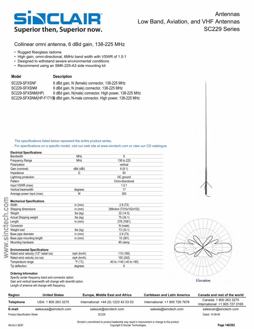
AntennasLow Band, Aviation, and VHF Antennas
SC229 Series
Collinear omni antenna, 6 dBd gain, 138-225 MHz• Rugged fiberglass radome• High gain, omni-directional, 6MHz band width with VSWR of 1.5:1• Designed to withstand severe environmental conditions• Recommend using an SMK-225-A3 side mounting kit
Model DescriptionSC229-SFXSNF 6 dBd gain, N (female) connector, 138-225 MHzSC229-SFXSNM 6 dBd gain, N (male) connector, 138-225 MHzSC229-SFXSNM(HP) 6 dBd gain, N(male) connector, High power, 138-225 MHzSC229-SFXSNM(HP-F1710)6 dBd gain, N-male connector, High power, 138-225 MHz
The specifications listed below represent the entire product series.For specifications on a specific model, visit our web site at www.sinctech.com or view our CD catalogue.
Electrical SpecificationsBandwidth MHz 6Frequency Range MHz 138 to 225Polarization verticalGain (nominal) dBd (dBi) 6 (8.1)Impedance Ω 50Lightning protection DC groundPattern Omni-directionalInput VSWR (max) 1.5:1Vertical beamwidth degrees 17Average power input (max) W 300
Mechanical SpecificationsWidth in (mm) 2.9 (73)Shipping dimensions in (mm) 288x4x4 (7315x102x102)Weight lbs (kg) 32 (14.5)Actual Shipping weight lbs (kg) 75 (34.1)Length in (mm) 278 (7061)Connector N (male)Weight iced lbs (kg) 73 (33.1)Base pipe diameter in (mm) 2.9 (73)Base pipe mounting length in (mm) 15 (381)Mounting hardware #5 clamp
Environmental SpecificationsRated wind velocity (1/2" radial ice) mph (km/h) 115 (185)Rated wind velocity (no ice) mph (km/h) 150 (242)Temperature range °F (°C) -40 to +140 (-40 to +60)Tip deflection degrees 6
Ordering InformationSpecify center frequency band and connector option.Gain and vertical beamwidth will change with downtilt option.Length of antenna will change with frequency.
Region United States Europe, Middle East and Africa Caribbean and Latin America Canada and rest of the world
Telephone USA: 1 800 263 3275 International: +44 (0) 1223 42 03 03 International: +1 905 726 7676 Canada: 1 800 263 3275International: +1 905 727 0165
E-mail [email protected] [email protected] [email protected] [email protected] Specification Sheet SC229 Dated: 10-09-09
Sinclair’s commitment to product leadership may result in improvement or change to this productCopyright © Sinclair TechnologiesAN.ALV.36/87 Page 148/202
www.
sinct
ech.
com

AntennasLow Band, Aviation, and VHF Antennas
SC229-L - PIM Certified Series
Collinear omni antenna, 6 dBd gain, low PIM, 138-174 MHz• Designed to withstand severe environmental conditions• Fiberglass radome with built in lighting protection• Provides excellent coverage and durability
Model DescriptionSC229-SFXLDF 6 dBd gain, 7/16 DIN (female) connector, 138-225 MHz
The specifications listed below represent the entire product series.For specifications on a specific model, visit our web site at www.sinctech.com or view our CD catalogue.
Electrical SpecificationsFrequency Range MHz 138 to 174Polarization verticalGain (nominal) dBd (dBi) 6 (8.1)Impedance Ω 50Lightning protection DC groundPassive intermod. (2x20W, 3rd ord.) dBc -150Pattern Omni-directionalInput VSWR (max) 1.5:1Vertical beamwidth degrees 17Average power input (max) W 300
Mechanical SpecificationsWidth in (mm) 3 (76)Shipping dimensions in (mm) 248x4x4 (6299x102x102)Weight lbs (kg) 32 (14.5)Actual Shipping weight lbs (kg) 75 (34.1)Length in (mm) 238 (6045)Connector 7/16 DIN (female)Weight iced lbs (kg) 73 (33.1)Base pipe diameter in (mm) 2.9 (73)Base pipe mounting length in (mm) 24 (610)Mounting hardware #5 clamp
Environmental SpecificationsRated wind velocity (1/2" radial ice) mph (km/h) 115 (185)Rated wind velocity (no ice) mph (km/h) 150 (242)Temperature range °F (°C) -40 to +140 (-40 to +60)Tip deflection degrees 6
Ordering InformationSpecify center of frequency band and connector option.Gain and vertical beamwidth will change with downtilt option.Length of antenna will change with frequency.
Region United States Europe, Middle East and Africa Caribbean and Latin America Canada and rest of the world
Telephone USA: 1 800 263 3275 International: +44 (0) 1223 42 03 03 International: +1 905 726 7676 Canada: 1 800 263 3275International: +1 905 727 0165
E-mail [email protected] [email protected] [email protected] [email protected] Specification Sheet SC229-L - PIM Certified Dated: 10-09-09
Sinclair’s commitment to product leadership may result in improvement or change to this productCopyright © Sinclair TechnologiesAN.ALV.37/87 Page 149/202
www.
sinct
ech.
com

AntennasLow Band, Aviation, and VHF Antennas
SC233 Series
Collinear omni antenna, 3 dBd gain, 138-174 MHz• Low cost antenna• Designed to withstand harsh environments• Excellent horizontal coverage
Model DescriptionSC233-SFXSNM 3 dBd gain, N (male) connector, 138-174 MHzSC233M-SFXSUM 3 dBd gain, UHF (male) connector, 156-162.5 MHz
The specifications listed below represent the entire product series.For specifications on a specific model, visit our web site at www.sinctech.com or view our CD catalogue.
Electrical SpecificationsBandwidth MHz 2Frequency Range MHz 138 to 174Polarization verticalGain (nominal) dBd (dBi) 3 (5.1)Impedance Ω 50Lightning protection DC groundPattern Omni-directionalInput VSWR (max) 1.5:1Vertical beamwidth degrees 35Average power input (max) W 60
Mechanical SpecificationsWidth in (mm) 1.5 (38)Depth in (mm) 1.5 (38)Shipping dimensions in (mm) 157x4x4 (3988x102x102)Weight lbs (kg) 3.5 (1.6)Actual Shipping weight lbs (kg) 20 (9.1)Length in (mm) 145 (3683)Connector N (male)Weight iced lbs (kg) 15 (6.8)Base pipe diameter in (mm) 0.9 (22)Base pipe mounting length in (mm) 14 (356)Mounting hardware #135B clamp
Environmental SpecificationsRated wind velocity (1/2" radial ice) mph (km/h) 85 (137)Rated wind velocity (no ice) mph (km/h) 115 (185)Temperature range °F (°C) -40 to +140 (-40 to +60)
Ordering InformationSpecify frequency band of operation.
Region United States Europe, Middle East and Africa Caribbean and Latin America Canada and rest of the world
Telephone USA: 1 800 263 3275 International: +44 (0) 1223 42 03 03 International: +1 905 726 7676 Canada: 1 800 263 3275International: +1 905 727 0165
E-mail [email protected] [email protected] [email protected] [email protected] Specification Sheet SC233 Dated: 10-09-09
Sinclair’s commitment to product leadership may result in improvement or change to this productCopyright © Sinclair TechnologiesAN.ALV.38/87 Page 150/202
www.
sinct
ech.
com

AntennasLow Band, Aviation, and VHF Antennas
SC272 Series
Collinear omni antenna, 0 dBd gain, 118-137 MHz• Designed for marine service under extreme conditions• Available in a PVC radome• Light weight
Model DescriptionSC272-SF1SNF 0 dBd gain, N (female) connector, 118-137 MHz
The specifications listed below represent the entire product series.For specifications on a specific model, visit our web site at www.sinctech.com or view our CD catalogue.
Electrical SpecificationsBandwidth MHz 18Frequency Range MHz 118 to 137Polarization verticalGain (nominal) dBd (dBi) unity (2.1)Lightning protection DC groundPattern Omni-directionalInput VSWR (max) 2:1Vertical beamwidth degrees 85Average power input (max) W 250
Mechanical SpecificationsWidth in (mm) 2.5 (64)Depth in (mm) 2.5 (64)Shipping dimensions in (mm) 75x4x4 (1905x102x102)Weight lbs (kg) 6.1 (2.8)Actual Shipping weight lbs (kg) 25 (11.4)Length in (mm) 65.5 (1664)Connector N (female)Weight iced lbs (kg) 12 (5.4)
Environmental SpecificationsRated wind velocity (1/2" radial ice) mph (km/h) 115 (185)Rated wind velocity (no ice) mph (km/h) 135 (217)Temperature range °F (°C) -40 to +140 (-40 to +60)Tip deflection degrees 3.8Projected area (Flat Plate Equivalent) ft² (m²) 0.56 (0.05)Projected area (ice) ft² (m²) 0.86 (0.08)Lateral thrust (100mph) lbs (N) 23 (102.3)
Region United States Europe, Middle East and Africa Caribbean and Latin America Canada and rest of the world
Telephone USA: 1 800 263 3275 International: +44 (0) 1223 42 03 03 International: +1 905 726 7676 Canada: 1 800 263 3275International: +1 905 727 0165
E-mail [email protected] [email protected] [email protected] [email protected] Specification Sheet SC272 Dated: 10-09-09
Sinclair’s commitment to product leadership may result in improvement or change to this productCopyright © Sinclair TechnologiesAN.ALV.39/87 Page 151/202
www.
sinct
ech.
com

AntennasLow Band, Aviation, and VHF Antennas
SC281-HL - PIM Certified Series
Collinear omni antenna, 5 dBd gain, low PIM, HD, 138-174 MHz• Wide band, covers 20 MHz in each band split- true omni pattern• 500W power handling with extremely low PIM: -150 dBc (2x20W carriers)• Recommend using the SMK-345-A7 side mounting kit.
Model DescriptionSC281-HF2LDF 5 dBd gain, 7/16 DIN (female) connector, 138-158 MHzSC281-HF3LDF 5 dBd gain, 7/16 DIN (female) connector, 148-168 MHzSC281-HF4LDF 5 dBd gain, 7/16 DIN (female) connector, 156-174 MHz
The specifications listed below represent the entire product series.For specifications on a specific model, visit our web site at www.sinctech.com or view our CD catalogue.
Electrical SpecificationsBandwidth MHz 20Frequency Range MHz 138 to 174Polarization verticalGain (nominal) dBd (dBi) 5 (7.1)Electrical tilt (available) 0,2,4Impedance Ω 50Null fill % 20Lightning protection DC groundPassive intermod. (2x20W, 3rd ord.) dBc -150Pattern Omni-directionalInput VSWR (max) 1.5:1Vertical beamwidth degrees 18Average power input (max) W 500
Mechanical SpecificationsWidth in (mm) 5 (127)Shipping dimensions in (mm) 264x6x6 (6706x152x152)Weight lbs (kg) 79 (35.9)Actual Shipping weight lbs (kg) 150 (68.1)Length in (mm) 251 (6375)Connector 7/16 DIN (female)Weight iced lbs (kg) 142 (64.5)Base pipe diameter in (mm) 5 (127)Base pipe mounting length in (mm) 30 (762)Mounting hardware clamps not supplied
Environmental SpecificationsRated wind velocity (1/2" radial ice) mph (km/h) 150 (242)
Ordering InformationSpecify frequency band of operation.Recommend using the SMK-345-A7 side mounting kit.
Region United States Europe, Middle East and Africa Caribbean and Latin America Canada and rest of the world
Telephone USA: 1 800 263 3275 International: +44 (0) 1223 42 03 03 International: +1 905 726 7676 Canada: 1 800 263 3275International: +1 905 727 0165
E-mail [email protected] [email protected] [email protected] [email protected] Specification Sheet SC281-HL - PIM Certified Dated: 10-09-09
Sinclair’s commitment to product leadership may result in improvement or change to this productCopyright © Sinclair TechnologiesAN.ALV.40/87 Page 152/202
www.
sinct
ech.
com

AntennasLow Band, Aviation, and VHF Antennas
SG101 Series
Ground plane omni antenna, 0 dBd gain, 30-88 MHz• 3-6.2% bandwidth• Designed for severe climatic conditions• Dependable performance
Model DescriptionSG101-SFXPASNM 0 dBd gain, Field adjustable, N (male) connector, 30-50 MHzSG101-SFXSNM 0 dBd gain, N (male) connector, 30-88 MHz
The specifications listed below represent the entire product series.For specifications on a specific model, visit our web site at www.sinctech.com or view our CD catalogue.
Electrical SpecificationsFrequency Range MHz 30 to 88Polarization verticalGain (nominal) dBd (dBi) unity (2.1)Lightning protection DC groundPattern Omni-directionalInput VSWR (max) 1.5:1Vertical beamwidth degrees 87Average power input (max) W 450
Mechanical SpecificationsLength/ Height in (mm) 115 (2921)Width in (mm) 201 (5105)Depth in (mm) 201 (5105)Shipping dimensions in (mm) 118x5x15 (2997x127x381)Weight lbs (kg) 35 (15.9)Actual Shipping weight lbs (kg) 25 (11.4)Length in (mm) 115 (2921)Connector N (male)Base pipe diameter in (mm) 1.9 (48)Base pipe mounting length in (mm) 36 (914)Mounting hardware #120 clamp
Environmental SpecificationsRated wind velocity (1/2" radial ice) mph (km/h) 85 (137)Rated wind velocity (no ice) mph (km/h) 100 (161)Temperature range °F (°C) -22 to +140 (-30 to +60)Projected area (ice) ft² (m²) 5 (0.46)Lateral thrust (100mph) lbs (N) 108 (480.4)
Region United States Europe, Middle East and Africa Caribbean and Latin America Canada and rest of the world
Telephone USA: 1 800 263 3275 International: +44 (0) 1223 42 03 03 International: +1 905 726 7676 Canada: 1 800 263 3275International: +1 905 727 0165
E-mail [email protected] [email protected] [email protected] [email protected] Specification Sheet SG101 Dated: 10-09-09
Sinclair’s commitment to product leadership may result in improvement or change to this productCopyright © Sinclair TechnologiesAN.ALV.41/87 Page 153/202
www.
sinct
ech.
com

AntennasLow Band, Aviation, and VHF Antennas
SG201 Series
Ground plane omni antenna, 0 dBd gain, 118-174 MHz• Wide band omni-directional ground plane antenna with unity gain• Easily field adjustable• Aluminum construction throughout
Model DescriptionSG201-SF1SNF 0 dBd gain, N female connector, 118-138 MHzSG201-SF1SNM 0 dBd gain, N male connector, 118-136 MHzSG201-SF2SNF 0 dBd gain, N female connector, 130-150 MHzSG201-SF2SNM 0 dBd gain, N male connector, 130-150 MHzSG201-SF3SNF 0 dBd gain, N female connector, 148-174 MHzSG201-SF3SNM 0 dBd gain, N male connector, 148-174 MHz
The specifications listed below represent the entire product series.For specifications on a specific model, visit our web site at www.sinctech.com or view our CD catalogue.
Electrical SpecificationsFrequency Range MHz 118 to 174Polarization verticalGain (nominal) dBd (dBi) unity (2.1)Lightning protection DC groundPattern Omni-directionalInput VSWR (max) 1.5:1Vertical beamwidth degrees 75Average power input (max) W 250
Mechanical SpecificationsLength/ Height in (mm) 64 (1626)Width in (mm) 56 (1422)Depth in (mm) 56 (1422)Shipping dimensions in (mm) 73x5x6 (1854x127x152)Weight lbs (kg) 8 (3.6)Actual Shipping weight lbs (kg) 15 (6.8)Connector N (male)Base pipe diameter in (mm) 1.5 (38)Base pipe mounting length in (mm) 12 (305)Mounting hardware #135 clamp
Environmental SpecificationsRated wind velocity (1/2" radial ice) mph (km/h) 85 (137)Rated wind velocity (no ice) mph (km/h) 130 (209)Temperature range °F (°C) -22 to +140 (-30 to +60)Projected area (Flat Plate Equivalent) ft² (m²) 1.47 (0.14)Projected area (ice) ft² (m²) 2.48 (0.23)Lateral thrust (100mph) lbs (N) 24.2 (107.6)
Ordering InformationN-female connector available upon request.Please specify connector and frequency band of operation.
Region United States Europe, Middle East and Africa Caribbean and Latin America Canada and rest of the world
Telephone USA: 1 800 263 3275 International: +44 (0) 1223 42 03 03 International: +1 905 726 7676 Canada: 1 800 263 3275International: +1 905 727 0165
E-mail [email protected] [email protected] [email protected] [email protected] Specification Sheet SG201 Dated: 10-09-09
Sinclair’s commitment to product leadership may result in improvement or change to this productCopyright © Sinclair TechnologiesAN.ALV.42/87 Page 154/202
www.
sinct
ech.
com

AntennasLow Band, Aviation, and VHF Antennas
SG217 Series
Ground plane omni antenna, 2.5 dBd gain, 118-174 MHz• Field adjustable• Omni-directional radiation pattern and 2.5 dBd gain• Excellent antenna to stock for re-use or re-sale
Model DescriptionSG217-SF1SNM 2.5 dBd gain, N (male) connector, 118-138 MHzSG217-SF1SUF 2.5 dBd gain, UHF (female) connector, 118-138 MHzSG217-SF2SNM 2.5 dBd gain, N (male) connector, 138-174 MHzSG217-SF2SUF 2.5 dBd gain, UHF (female) connector, 138-174 MHz
The specifications listed below represent the entire product series.For specifications on a specific model, visit our web site at www.sinctech.com or view our CD catalogue.
Electrical SpecificationsFrequency Range MHz 118 to 174Polarization verticalGain (nominal) dBd (dBi) 2.5 (4.6)Lightning protection DC groundPattern Omni-directionalInput VSWR (max) 1.5:1Vertical beamwidth degrees 40Average power input (max) W 250
Mechanical SpecificationsLength/ Height in (mm) 128 (3251)Width in (mm) 58 (1473)Shipping dimensions in (mm) 73x5x6 (1854x127x152)Weight lbs (kg) 6.5 (3)Actual Shipping weight lbs (kg) 15 (6.8)Connector N (male)Base pipe diameter in (mm) 1.5 (38)Mounting hardware #135 clamp
Environmental SpecificationsRated wind velocity (1/2" radial ice) mph (km/h) 85 (137)Rated wind velocity (no ice) mph (km/h) 125 (201)Temperature range °F (°C) -22 to +140 (-30 to +60)Projected area (Flat Plate Equivalent) ft² (m²) 1.22 (0.11)Projected area (ice) ft² (m²) 2.24 (0.21)Lateral thrust (100mph) lbs (N) 65 (289.1)Bending moment ft-lbs (Nm) 224 (302.4)
Ordering InformationUHF-Female connector also available upon request.Please specify connector and order of frequency upon request.
Region United States Europe, Middle East and Africa Caribbean and Latin America Canada and rest of the world
Telephone USA: 1 800 263 3275 International: +44 (0) 1223 42 03 03 International: +1 905 726 7676 Canada: 1 800 263 3275International: +1 905 727 0165
E-mail [email protected] [email protected] [email protected] [email protected] Specification Sheet SG217 Dated: 10-09-09
Sinclair’s commitment to product leadership may result in improvement or change to this productCopyright © Sinclair TechnologiesAN.ALV.43/87 Page 155/202
www.
sinct
ech.
com

AntennasLow Band, Aviation, and VHF Antennas
SG238 Series
Ground plane omni antenna, 0 dBd gain, 118-174 MHz• Broadband omni-directional antenna for ground-to-air applications• Constructed of selected aluminum alloy and stainless steel• A heavy-duty version is also available
Model DescriptionSG238-SF1SNM 0 dBd gain, N (male) connector, 118-136 MHzSG238-SF2SNM 0 dBd gain, N (male) connector, 136-160 MHzSG238-SF3SNM 0 dBd gain, N (male) connector, 150-174 MHz
The specifications listed below represent the entire product series.For specifications on a specific model, visit our web site at www.sinctech.com or view our CD catalogue.
Electrical SpecificationsFrequency Range MHz 118 to 174Polarization verticalGain (nominal) dBd (dBi) unity (2.1)Lightning protection DC groundPattern Omni-directionalInput VSWR (max) 2:1Vertical beamwidth degrees 71Average power input (max) W 250
Mechanical SpecificationsLength/ Height in (mm) 67 (1702)Width in (mm) 26.5 (673)Shipping dimensions in (mm) 73x5x6 (1854x127x152)Weight lbs (kg) 15 (6.8)Actual Shipping weight lbs (kg) 21.5 (9.8)Connector N (male)Base pipe diameter in (mm) 1.5 (38)Base pipe mounting length in (mm) 15 (381)
Environmental SpecificationsRated wind velocity (1/2" radial ice) mph (km/h) 110 (177)Rated wind velocity (no ice) mph (km/h) 125 (201)Temperature range °F (°C) -40 to +140 (-40 to +60)Projected area (ice) ft² (m²) 1.98 (0.18)Lateral thrust (100mph) lbs (N) 65 (289.1)
Ordering InformationSpecify frequency band of operation.
Region United States Europe, Middle East and Africa Caribbean and Latin America Canada and rest of the world
Telephone USA: 1 800 263 3275 International: +44 (0) 1223 42 03 03 International: +1 905 726 7676 Canada: 1 800 263 3275International: +1 905 727 0165
E-mail [email protected] [email protected] [email protected] [email protected] Specification Sheet SG238 Dated: 10-09-09
Sinclair’s commitment to product leadership may result in improvement or change to this productCopyright © Sinclair TechnologiesAN.ALV.44/87 Page 156/202
www.
sinct
ech.
com

AntennasLow Band, Aviation, and VHF Antennas
SG238-H Series
Ground plane omni antenna, 0 dBd gain, HD, 118-174 MHz• Broadband omni-directional antenna for ground-to-air applications• Constructed of selected aluminum alloy and stainless steel• Heavy duty version
Model DescriptionSG238-HF1SNM 0 dBd gain, N (male) connector, 118-136 MHzSG238-HF2SNM 0 dBd gain, N (male) connector, 136-160 MHzSG238-HF3SNM 0 dBd gain, N (male) connector, 150-174 MHz
The specifications listed below represent the entire product series.For specifications on a specific model, visit our web site at www.sinctech.com or view our CD catalogue.
Electrical SpecificationsFrequency Range MHz 118 to 174Polarization verticalGain (nominal) dBd (dBi) unity (2.1)Lightning protection DC groundPattern Omni-directionalInput VSWR (max) 2:1Vertical beamwidth degrees 71Average power input (max) W 250
Mechanical SpecificationsLength/ Height in (mm) 67 (1702)Width in (mm) 26.5 (673)Shipping dimensions in (mm) 86x7x8 (2184x178x203)Weight lbs (kg) 21.2 (9.6)Actual Shipping weight lbs (kg) 25 (11.4)Connector N (male)Base pipe diameter in (mm) 1.5 (38)Base pipe mounting length in (mm) 15 (381)
Environmental SpecificationsRated wind velocity (1/2" radial ice) mph (km/h) 115 (185)Rated wind velocity (no ice) mph (km/h) 195 (314)Temperature range °F (°C) -40 to +140 (-40 to +60)Projected area (ice) ft² (m²) 2 (0.19)Lateral thrust (100mph) lbs (N) 30.7 (136.4)
Ordering InformationSpecify frequency of operation.
Region United States Europe, Middle East and Africa Caribbean and Latin America Canada and rest of the world
Telephone USA: 1 800 263 3275 International: +44 (0) 1223 42 03 03 International: +1 905 726 7676 Canada: 1 800 263 3275International: +1 905 727 0165
E-mail [email protected] [email protected] [email protected] [email protected] Specification Sheet SG238-H Dated: 10-09-09
Sinclair’s commitment to product leadership may result in improvement or change to this productCopyright © Sinclair TechnologiesAN.ALV.45/87 Page 157/202
www.
sinct
ech.
com
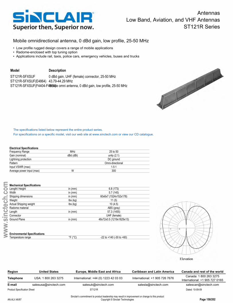
AntennasLow Band, Aviation, and VHF Antennas
ST121R Series
Mobile omnidirectional antenna, 0 dBd gain, low profile, 25-50 MHz• Low profile rugged design covers a range of mobile applications• Radome-enclosed with top tuning option• Applications include rail, taxis, police cars, emergency vehicles, buses and trucks
Model DescriptionST121R-SFXSUF 0 dBd gain, UHF (female) connector, 25-50 MHzST121R-SFXSUF(E4864) 43.79-44.29 MHzST121R-SFXSUF(F4404-F4864)Mobile omni antenna, 0 dBd gain, low profile, 25-50 MHz
The specifications listed below represent the entire product series.For specifications on a specific model, visit our web site at www.sinctech.com or view our CD catalogue.
Electrical SpecificationsFrequency Range MHz 25 to 50Gain (nominal) dBd (dBi) unity (2.1)Lightning protection DC groundPattern Omni-directionalInput VSWR (max) 1.5:1Average power input (max) W 300
Mechanical SpecificationsLength/ Height in (mm) 6.8 (173)Width in (mm) 5.7 (145)Shipping dimensions in (mm) 60x6x7 (1524x152x178)Weight lbs (kg) 11 (5)Actual Shipping weight lbs (kg) 10 (4.5)Radome material ABS (gray)Length in (mm) 57.3 (1455)Connector UHF (female)Ground Plane in (mm) 48x72x0.5 (1219x1829x13)
Environmental SpecificationsTemperature range °F (°C) -22 to +140 (-30 to +60)
Region United States Europe, Middle East and Africa Caribbean and Latin America Canada and rest of the world
Telephone USA: 1 800 263 3275 International: +44 (0) 1223 42 03 03 International: +1 905 726 7676 Canada: 1 800 263 3275International: +1 905 727 0165
E-mail [email protected] [email protected] [email protected] [email protected] Specification Sheet ST121R Dated: 10-09-09
Sinclair’s commitment to product leadership may result in improvement or change to this productCopyright © Sinclair TechnologiesAN.ALV.46/87 Page 158/202
www.
sinct
ech.
com

AntennasLow Band, Aviation, and VHF Antennas
ST221 Series
Mobile omni antenna, 0 dBd gain, low profile, 138-222 MHz• Low profile for a wide range of mobile applications• Cast aluminum• 2.5 MHz bandwidth• Applications include: trains, taxis, police cars, emergency vehicles, buses and trucks
Model DescriptionST221-SF1SNF(FXXXX) 0 dBd gain, N-female connector, 138-163 MHzST221-SF1SUF(FXXXX) 0 dBd gain, UHF- female connector, 138-163 MHzST221-SF2SNF(FXXXX) 0 dBd gain, N-female connector, 162-174 MHzST221-SF2SUF(FXXXX) 0 dBd gain, UHF-female connector, 162-174 MHzST221-SF3SNF 220-222 MHzST221-SF3SUF 220-222 MHz
The specifications listed below represent the entire product series.For specifications on a specific model, visit our web site at www.sinctech.com or view our CD catalogue.
Electrical SpecificationsBandwidth MHz 2.5Frequency Range MHz 138 to 222Polarization verticalGain (nominal) dBd (dBi) unity (2.1)Impedance Ω 50Lightning protection DC groundPattern Omni-directionalInput VSWR (max) 1.5:1Average power input (max) W 300
Mechanical SpecificationsLength/ Height in (mm) 4 (102)Width in (mm) 2.2 (56)Depth in (mm) 24.5 (622)Shipping dimensions in (mm) 26x6x4in ()Weight lbs (kg) 6 (2.7)Actual Shipping weight lbs (kg) 7 (3.2)Connector UHF (female)Mounting hardware Supplied
Environmental SpecificationsTemperature range °F (°C) -22 to +140 (-30 to +60)
Ordering InformationSpecify exact frequency.Specify connector type - UHF-female or N-female
Region United States Europe, Middle East and Africa Caribbean and Latin America Canada and rest of the world
Telephone USA: 1 800 263 3275 International: +44 (0) 1223 42 03 03 International: +1 905 726 7676 Canada: 1 800 263 3275International: +1 905 727 0165
E-mail [email protected] [email protected] [email protected] [email protected] Specification Sheet ST221 Dated: 10-09-09
Sinclair’s commitment to product leadership may result in improvement or change to this productCopyright © Sinclair TechnologiesAN.ALV.47/87 Page 159/202
www.
sinct
ech.
com
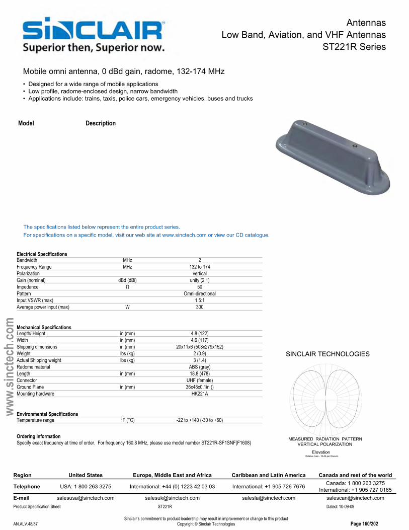
AntennasLow Band, Aviation, and VHF Antennas
ST221R Series
Mobile omni antenna, 0 dBd gain, radome, 132-174 MHz• Designed for a wide range of mobile applications• Low profile, radome-enclosed design, narrow bandwidth• Applications include: trains, taxis, police cars, emergency vehicles, buses and trucks
Model Description
The specifications listed below represent the entire product series.For specifications on a specific model, visit our web site at www.sinctech.com or view our CD catalogue.
Electrical SpecificationsBandwidth MHz 2Frequency Range MHz 132 to 174Polarization verticalGain (nominal) dBd (dBi) unity (2.1)Impedance Ω 50Pattern Omni-directionalInput VSWR (max) 1.5:1Average power input (max) W 300
Mechanical SpecificationsLength/ Height in (mm) 4.8 (122)Width in (mm) 4.6 (117)Shipping dimensions in (mm) 20x11x6 (508x279x152)Weight lbs (kg) 2 (0.9)Actual Shipping weight lbs (kg) 3 (1.4)Radome material ABS (gray)Length in (mm) 18.8 (478)Connector UHF (female)Ground Plane in (mm) 36x48x0.1in ()Mounting hardware HK221A
Environmental SpecificationsTemperature range °F (°C) -22 to +140 (-30 to +60)
Ordering InformationSpecify exact frequency at time of order. For frequency 160.8 MHz, please use model number ST221R-SF1SNF(F1608)
Region United States Europe, Middle East and Africa Caribbean and Latin America Canada and rest of the world
Telephone USA: 1 800 263 3275 International: +44 (0) 1223 42 03 03 International: +1 905 726 7676 Canada: 1 800 263 3275International: +1 905 727 0165
E-mail [email protected] [email protected] [email protected] [email protected] Specification Sheet ST221R Dated: 10-09-09
Sinclair’s commitment to product leadership may result in improvement or change to this productCopyright © Sinclair TechnologiesAN.ALV.48/87 Page 160/202
www.
sinct
ech.
com
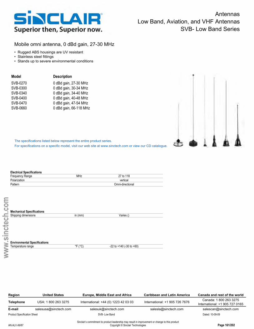
AntennasLow Band, Aviation, and VHF Antennas
SVB- Low Band Series
Mobile omni antenna, 0 dBd gain, 27-30 MHz• Rugged ABS housings are UV resistant• Stainless steel fittings• Stands up to severe environmental conditions
Model DescriptionSVB-0270 0 dBd gain, 27-30 MHzSVB-0300 0 dBd gain, 30-34 MHzSVB-0340 0 dBd gain, 34-40 MHzSVB-0400 0 dBd gain, 40-48 MHzSVB-0470 0 dBd gain, 47-54 MHzSVB-0660 0 dBd gain, 66-118 MHz
The specifications listed below represent the entire product series.For specifications on a specific model, visit our web site at www.sinctech.com or view our CD catalogue.
Electrical SpecificationsFrequency Range MHz 27 to 118Polarization verticalPattern Omni-directional
Mechanical SpecificationsShipping dimensions in (mm) Varies ()
Environmental SpecificationsTemperature range °F (°C) -22 to +140 (-30 to +60)
Region United States Europe, Middle East and Africa Caribbean and Latin America Canada and rest of the world
Telephone USA: 1 800 263 3275 International: +44 (0) 1223 42 03 03 International: +1 905 726 7676 Canada: 1 800 263 3275International: +1 905 727 0165
E-mail [email protected] [email protected] [email protected] [email protected] Specification Sheet SVB- Low Band Dated: 10-09-09
Sinclair’s commitment to product leadership may result in improvement or change to this productCopyright © Sinclair TechnologiesAN.ALV.49/87 Page 161/202
www.
sinct
ech.
com

AntennasLow Band, Aviation, and VHF Antennas
SVB- VHF Series
Mobile omni antenna• Rugged ABS housings are UV resistant• Stainless steel fittings• Stands up to severe environmental conditions
Model DescriptionSVB-1383 3 dBd gain, 138-174 MHzSVB-1482 2 dBd gain, 1/2 wave, 132-174 MHzSVB-1560 0 dBd gain, 1/4 wave, 138-174 MHzSVB-2202 2 dBd gain, 1/2 wave, 200-250 MHzSVB-2203 3 dBd gain, 5/8 wave, 200-250 MHz
The specifications listed below represent the entire product series.For specifications on a specific model, visit our web site at www.sinctech.com or view our CD catalogue.
Electrical SpecificationsFrequency Range MHz 138 to 174Polarization verticalPattern Omni-directionalAverage power input (max) W 100
Mechanical SpecificationsShipping dimensions in (mm) Varies ()
Environmental SpecificationsTemperature range °F (°C) -22 to +140 (-30 to +60)
Region United States Europe, Middle East and Africa Caribbean and Latin America Canada and rest of the world
Telephone USA: 1 800 263 3275 International: +44 (0) 1223 42 03 03 International: +1 905 726 7676 Canada: 1 800 263 3275International: +1 905 727 0165
E-mail [email protected] [email protected] [email protected] [email protected] Specification Sheet SVB- VHF Dated: 10-09-09
Sinclair’s commitment to product leadership may result in improvement or change to this productCopyright © Sinclair TechnologiesAN.ALV.50/87 Page 162/202
www.
sinct
ech.
com
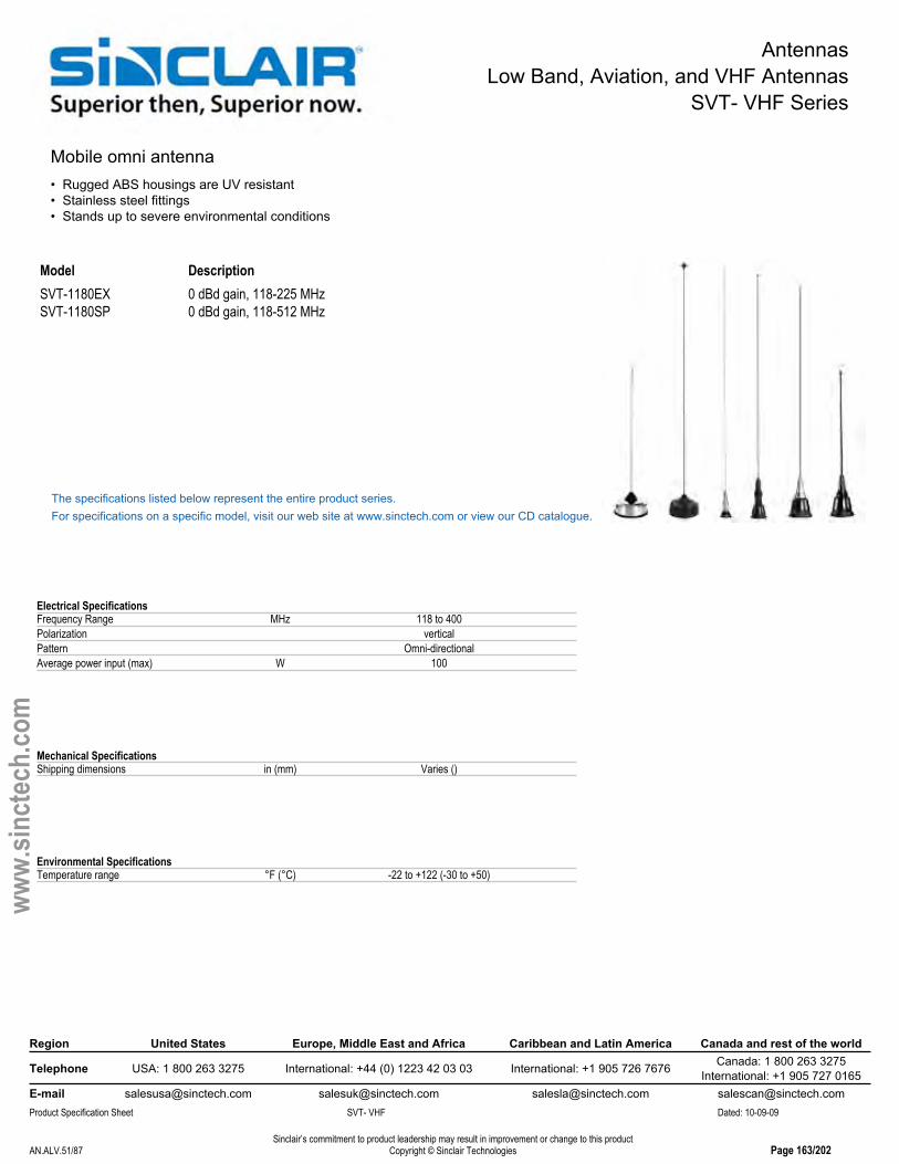
AntennasLow Band, Aviation, and VHF Antennas
SVT- VHF Series
Mobile omni antenna• Rugged ABS housings are UV resistant• Stainless steel fittings• Stands up to severe environmental conditions
Model DescriptionSVT-1180EX 0 dBd gain, 118-225 MHzSVT-1180SP 0 dBd gain, 118-512 MHz
The specifications listed below represent the entire product series.For specifications on a specific model, visit our web site at www.sinctech.com or view our CD catalogue.
Electrical SpecificationsFrequency Range MHz 118 to 400Polarization verticalPattern Omni-directionalAverage power input (max) W 100
Mechanical SpecificationsShipping dimensions in (mm) Varies ()
Environmental SpecificationsTemperature range °F (°C) -22 to +122 (-30 to +50)
Region United States Europe, Middle East and Africa Caribbean and Latin America Canada and rest of the world
Telephone USA: 1 800 263 3275 International: +44 (0) 1223 42 03 03 International: +1 905 726 7676 Canada: 1 800 263 3275International: +1 905 727 0165
E-mail [email protected] [email protected] [email protected] [email protected] Specification Sheet SVT- VHF Dated: 10-09-09
Sinclair’s commitment to product leadership may result in improvement or change to this productCopyright © Sinclair TechnologiesAN.ALV.51/87 Page 163/202
www.
sinct
ech.
com

AntennasLow Band, Aviation, and VHF Antennas
SC6172D Series
Aviation band antenna, 1 dBi gain, dual feed, HD, 118-137 MHz• Ideal for severe weather conditions at airports• Available with bird resistant cap and 3 ft. extension cable• For single feed version, model number is SC6172(E2712)
Model DescriptionSC6172(E2712) 1 dBi gain, single feed cable, N (female) connector, 118-137 MHzSC6172(E3818) 1 dBi, dual feed, 3' feed cable, 118-137 MHzSC6172D 1 dBi gain, dual feed, N (female) connector, 118-137 MHz
The specifications listed below represent the entire product series.For specifications on a specific model, visit our web site at www.sinctech.com or view our CD catalogue.
Electrical SpecificationsFrequency Range MHz 118 to 137Polarization verticalGain (nominal) dBd (dBi) -1.2 (0.9)Lightning protection DC groundPattern Omni-directionalInput VSWR (max) 2:1Vertical beamwidth degrees 75Average power input (max) W 100
Mechanical SpecificationsWidth in (mm) 3.5 (89)Shipping dimensions in (mm) 160x5x5 (4064x127x127)Weight lbs (kg) 38 (17.3)Actual Shipping weight lbs (kg) 65 (29.5)Length in (mm) 149.3 (3791)Connector N (female)Weight iced lbs (kg) 165 (74.9)Base pipe diameter in (mm) 4 (102)
Environmental SpecificationsRated wind velocity (1/2" radial ice) mph (km/h) 150 (242)Rated wind velocity (no ice) mph (km/h) 220 (354)Temperature range °F (°C) -40 to +140 (-40 to +60)Tip deflection degrees 0.6Projected area (Flat Plate Equivalent) ft² (m²) 2.42 (0.22)Projected area (ice) ft² (m²) 4.62 (0.43)Lateral thrust (100mph) lbs (N) 96 (427)Bending moment ft-lbs (Nm) 550 (742.5)
Region United States Europe, Middle East and Africa Caribbean and Latin America Canada and rest of the world
Telephone USA: 1 800 263 3275 International: +44 (0) 1223 42 03 03 International: +1 905 726 7676 Canada: 1 800 263 3275International: +1 905 727 0165
E-mail [email protected] [email protected] [email protected] [email protected] Specification Sheet SC6172D Dated: 10-09-09
Sinclair’s commitment to product leadership may result in improvement or change to this productCopyright © Sinclair TechnologiesAN.ALV.52/87 Page 164/202
www.
sinct
ech.
com

AntennasLow Band, Aviation, and VHF Antennas
SC6175D Series
Aviation band antenna, 1 dBd gain, dual feed, HD, 118-137 & 225-400 MHz• Ideal for severe weather conditions at airports• Available in dual band configuration only• Available with bird resistant cap and 3 ft. extension cable
Model DescriptionSC6175D 1 dBd gain, dual, N (female) connector, 118-137 & 225-400 MHz
The specifications listed below represent the entire product series.For specifications on a specific model, visit our web site at www.sinctech.com or view our CD catalogue.
Electrical SpecificationsFrequency Range MHz 118 to 400Polarization verticalGain (nominal) dBd (dBi) 1 (3.1)Impedance Ω 50Pattern Omni-directionalInput VSWR (max) 2:1Vertical beamwidth degrees 85Average power input (max) W 100
Mechanical SpecificationsWidth in (mm) 3.4 (87)Shipping dimensions in (mm) 110x5x5 (2794x127x127)Weight lbs (kg) 27.5 (12.5)Actual Shipping weight lbs (kg) 35 (15.9)Length in (mm) 98.5 (2502)Connector N (female)
Environmental SpecificationsTemperature range °F (°C) -40 to +158 (-40 to +70)
Region United States Europe, Middle East and Africa Caribbean and Latin America Canada and rest of the world
Telephone USA: 1 800 263 3275 International: +44 (0) 1223 42 03 03 International: +1 905 726 7676 Canada: 1 800 263 3275International: +1 905 727 0165
E-mail [email protected] [email protected] [email protected] [email protected] Specification Sheet SC6175D Dated: 10-09-09
Sinclair’s commitment to product leadership may result in improvement or change to this productCopyright © Sinclair TechnologiesAN.ALV.53/87 Page 165/202
www.
sinct
ech.
com

AntennasLow Band, Aviation, and VHF Antennas
SC6185 Series
Aviation band antenna, 0.9-2.9 dBd gain, HD, 225-400 MHz• Ideal for severe weather conditions at airports• Available in single antenna model only• Available with bird resistant cap and 3 ft. extension cable
Model DescriptionSC6185 3 dBd gain, HD, N (male) connector, 225-400 MHz
The specifications listed below represent the entire product series.For specifications on a specific model, visit our web site at www.sinctech.com or view our CD catalogue.
Electrical SpecificationsFrequency Range MHz 225 to 400Polarization verticalGain (nominal) dBd (dBi) 0.9 (3)Electrical tilt (available) 2-6Lightning protection DC groundPattern Omni-directionalInput VSWR (max) 2.5:1Vertical beamwidth degrees 30Average power input (max) W 100
Mechanical SpecificationsWidth in (mm) 4 (102)Depth in (mm) 4 (102)Shipping dimensions in (mm) 90x6x6 (2286x152x152)Weight lbs (kg) 24.5 (11.1)Actual Shipping weight lbs (kg) 36 (16.3)Length in (mm) 76 (1930)Connector N (male)Weight iced lbs (kg) 39.5 (17.9)Base pipe diameter in (mm) 4 (102)Base pipe mounting length in (mm) 10 (254)
Environmental SpecificationsRated wind velocity (1/2" radial ice) mph (km/h) 225 (362)Rated wind velocity (no ice) mph (km/h) 275 (443)Temperature range °F (°C) -40 to +140 (-40 to +60)Tip deflection degrees 0.1Projected area (Flat Plate Equivalent) ft² (m²) 1.22 (0.11)
Region United States Europe, Middle East and Africa Caribbean and Latin America Canada and rest of the world
Telephone USA: 1 800 263 3275 International: +44 (0) 1223 42 03 03 International: +1 905 726 7676 Canada: 1 800 263 3275International: +1 905 727 0165
E-mail [email protected] [email protected] [email protected] [email protected] Specification Sheet SC6185 Dated: 10-09-09
Sinclair’s commitment to product leadership may result in improvement or change to this productCopyright © Sinclair TechnologiesAN.ALV.54/87 Page 166/202
www.
sinct
ech.
com

Transmitter CombinersLow Band, Aviation, and VHF Transmitter Combiners
CS2 Series
VHF Combiner, cavity-ferrite, 8.5" 1/4 wave, 125W load• Available in 2 to 6 channel 132-174 MHz configurations• Low loss dual isolator with -30 dB BNC sampler port per channel• Very high Q 8 1/2" bandpass cavity filter fits vertically side by side in 19" rack
Model DescriptionCS2211-1C VHF Single 8.5" 1/4 wave, Tx channel with cable, 132-150 MHzCS2211-1S VHF Single 8.5" 1/4 wave, Tx channel with SC, 132-150 MHzCS2211-2C VHF Single 8.5" 1/4 wave, Tx channel with cable, 150-174 MHzCS2211-2S VHF Single 8.5" 1/4 wave, Tx channel with SC, 150-174 MHzCS2211F(DF) VHF Combiner, cavity-ferrite, 8.5" 1/4 wave, 1-channel, rack, 125W loadCS2211F(NF) VHF Combiner, cavity-ferrite, 8.5" 1/4 wave, 1-channel, rack, 125W loadCS2212 VHF Combiner, cavity-ferrite, 8.5" 1/4 wave, 2-channel, 125W loadCS2212F(DF) VHF Combiner, cavity-ferrite, 8.5" 1/4 wave, 2-channel, rack, 125W loadCS2212F(NF) VHF Combiner, cavity-ferrite, 8.5" 1/4 wave, 2-channel, rack, 125W loadCS2213 VHF Combiner, cavity-ferrite, 8.5" 1/4 wave, 3-channel, 125W loadCS2213F(DF) VHF Combiner, cavity-ferrite, 8.5" 1/4 wave, 3-channel, rack, 125W loadCS2213F(NF) VHF Combiner, cavity-ferrite, 8.5" 1/4 wave, 3-channel, rack, 125W load

Transmitter CombinersLow Band, Aviation, and VHF Transmitter Combiners
CS2 Series
Region United States Europe, Middle East and Africa Caribbean and Latin America Canada and rest of the world
Telephone USA: 1 800 263 3275 International: +44 (0) 1223 42 03 03 International: +1 905 726 7676 Canada: 1 800 263 3275International: +1 905 727 0165
E-mail [email protected] [email protected] [email protected] [email protected] Specification Sheet CS2 Dated: 10-09-09
Sinclair’s commitment to product leadership may result in improvement or change to this productCopyright © Sinclair TechnologiesAN.ALV.56/87 Page 168/202
www.
sinct
ech.
com
CS2214 VHF Combiner, cavity-ferrite, 8.5" 1/4 wave, 4-channel, 125W loadCS2214F(DF) VHF Combiner, cavity-ferrite, 8.5" 1/4 wave, 4-channel, rack, 125W loadCS2214F(NF) VHF Combiner, cavity-ferrite, 8.5" 1/4 wave, 4-channel, rack, 125W load
The specifications listed below represent the entire product series.For specifications on a specific model, visit our web site at www.sinctech.com or view our CD catalogue.
Electrical SpecificationsFrequency Range MHz 132 to 174Input VSWR (max) 1.25:1Average power input (max) W 125Isolation Tx to Tx dB 70Cavity electrical length 1/4
Mechanical SpecificationsCavity width or diameter in (mm) 8.5 (216)Input connector N (female)Output connector N (female)Outer conductor material aluminumFinish Black
Environmental SpecificationsTemperature range °F (°C) -22 to +140 (-30 to +60)
Region United States Europe, Middle East and Africa Caribbean and Latin America Canada and rest of the world
Telephone USA: 1 800 263 3275 International: +44 (0) 1223 42 03 03 International: +1 905 726 7676 Canada: 1 800 263 3275International: +1 905 727 0165
E-mail [email protected] [email protected] [email protected] [email protected] Specification Sheet CS2 Dated: 10-09-09
Sinclair’s commitment to product leadership may result in improvement or change to this productCopyright © Sinclair TechnologiesAN.ALV.56/87 Page 168/202
www.
sinct
ech.
com
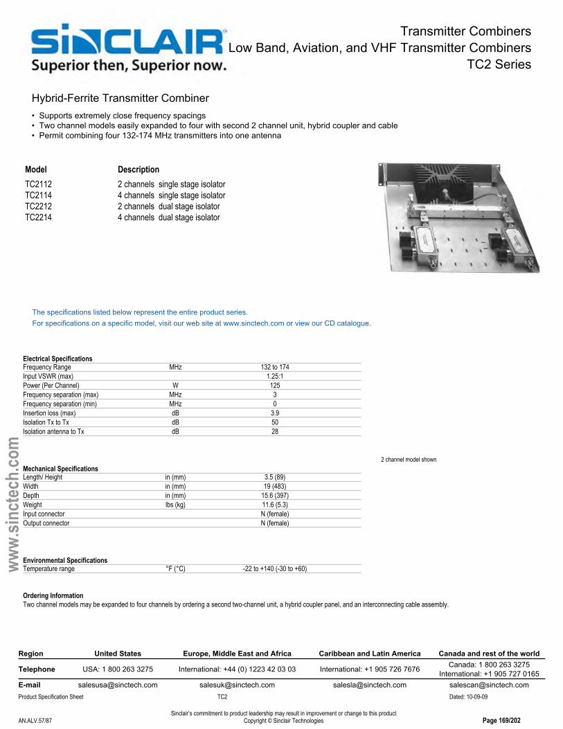
Transmitter CombinersLow Band, Aviation, and VHF Transmitter Combiners
TC2 Series
Hybrid-Ferrite Transmitter Combiner• Supports extremely close frequency spacings• Two channel models easily expanded to four with second 2 channel unit, hybrid coupler and cable• Permit combining four 132-174 MHz transmitters into one antenna
2 channel model shown
Model DescriptionTC2112 2 channels single stage isolatorTC2114 4 channels single stage isolatorTC2212 2 channels dual stage isolatorTC2214 4 channels dual stage isolator
The specifications listed below represent the entire product series.For specifications on a specific model, visit our web site at www.sinctech.com or view our CD catalogue.
Electrical SpecificationsFrequency Range MHz 132 to 174Input VSWR (max) 1.25:1Power (Per Channel) W 125Frequency separation (max) MHz 3Frequency separation (min) MHz 0Insertion loss (max) dB 3.9Isolation Tx to Tx dB 50Isolation antenna to Tx dB 28
Mechanical SpecificationsLength/ Height in (mm) 3.5 (89)Width in (mm) 19 (483)Depth in (mm) 15.6 (397)Weight lbs (kg) 11.6 (5.3)Input connector N (female)Output connector N (female)
Environmental SpecificationsTemperature range °F (°C) -22 to +140 (-30 to +60)
Ordering InformationTwo channel models may be expanded to four channels by ordering a second two-channel unit, a hybrid coupler panel, and an interconnecting cable assembly.
Region United States Europe, Middle East and Africa Caribbean and Latin America Canada and rest of the world
Telephone USA: 1 800 263 3275 International: +44 (0) 1223 42 03 03 International: +1 905 726 7676 Canada: 1 800 263 3275International: +1 905 727 0165
E-mail [email protected] [email protected] [email protected] [email protected] Specification Sheet TC2 Dated: 10-09-09
Sinclair’s commitment to product leadership may result in improvement or change to this productCopyright © Sinclair TechnologiesAN.ALV.57/87 Page 169/202
www.
sinct
ech.
com

Transmitter CombinersLow Band, Aviation, and VHF Transmitter Combiners
TJ2 Series
Cavity-Ferrite Transmitter Combiner, 7" Cans• Available in 2 to 5 channel 132-174 MHz configurations• Low loss single or dual isolator per channel• Uses high Q bandpass cavity filters
Model DescriptionTJ2112 2 channels single stage isolatorsTJ2113 3 channels single stage isolatorsTJ2114 4 channels single stage isolatorsTJ2115 5 channels single stage isolatorsTJ2212 2 channels dual stage isolatorsTJ2213 3 channels dual stage isolatorsTJ2214 4 channels dual stage isolatorsTJ2215 5 channels dual stage isolators
The specifications listed below represent the entire product series.For specifications on a specific model, visit our web site at www.sinctech.com or view our CD catalogue.
Electrical SpecificationsFrequency Range MHz 138 to 174Input VSWR (max) 1.25:1Power (Per Channel) W 125Frequency separation (min) MHz 0.15Insertion loss (max) dB 3.2Isolation Tx to Tx dB 70Isolation antenna to Tx dB 60Output VSWR 2:1Number of channels 2
Mechanical SpecificationsLength/ Height in (mm) 30.5 (775)Width in (mm) 19 (483)Depth in (mm) 7.5 (191)Weight lbs (kg) 17 (7.7)Cavity width or diameter in (mm) 7 (178)Number of cavities 2Input connector N (female)Output connector N (female)Outer conductor material aluminumFinish chemical conversion
Environmental SpecificationsTemperature range °F (°C) -22 to +140 (-30 to +60)
Region United States Europe, Middle East and Africa Caribbean and Latin America Canada and rest of the world
Telephone USA: 1 800 263 3275 International: +44 (0) 1223 42 03 03 International: +1 905 726 7676 Canada: 1 800 263 3275International: +1 905 727 0165
E-mail [email protected] [email protected] [email protected] [email protected] Specification Sheet TJ2 Dated: 10-09-09
Sinclair’s commitment to product leadership may result in improvement or change to this productCopyright © Sinclair TechnologiesAN.ALV.58/87 Page 170/202
www.
sinct
ech.
com

Receiver MulticouplersLow Band, Aviation, and VHF Receiver Multicouplers
RM2 Series
VHF Bipolar Receiver Mulitcoupler• Connect 2 to 16 receivers to a single antenna• Power supply options include 115/230 VAC and 12/24/48 VDC• Standard 1 MHz preselector with 40 dB attenuation 4.5 MHz away from band center
4 channel model shown
Model DescriptionRM201-102S1B VHF Bipolar Receive MulticouplerRM201-104G1B 1 MHz bandwidth, 138-150 MHz, 4 channels, 115 VAC power
supply, BNC-female outputsRM201-104S2B VHF Bipolar Receive MulticouplerRM201-108S1B 1 MHz bandwidth, 138-150 MHz, 8 channels, 115 VAC power
supply, BNC-female outputsRM201-112S1B 1 MHz bandwidth, 138-150 MHz, 12 channels, 115 VAC power
supply, BNC-female outputsRM201-216S1B VHF Bipolar Receive Multicoupler
The specifications listed below represent the entire product series.For specifications on a specific model, visit our web site at www.sinctech.com or view our CD catalogue.
Electrical SpecificationsBandwidth MHz 1Frequency Range MHz 138 to 174Input VSWR (max) 1.5:1Isolation Rx to Rx dB 25Output VSWR 1.5:1System gain (min) dB 1Noise figure (amplifier (typ)) dB 1.6Noise figure (system (typ)) dB 4.7Third order intercept - amplifier dBm 391 dB Compression point dBm 26
Mechanical SpecificationsLength/ Height in (mm) 1.8 (45)Width in (mm) 19 (483)Depth in (mm) 10 (254)Shipping dimensions in (mm) 23x18x4 (584x457x102)Weight lbs (kg) 5 (2.3)Actual Shipping weight lbs (kg) 10 (4.5)Input connector N (female)Output connector BNC (female)
Environmental SpecificationsTemperature range °F (°C) -22 to +140 (-30 to +60)
Region United States Europe, Middle East and Africa Caribbean and Latin America Canada and rest of the world
Telephone USA: 1 800 263 3275 International: +44 (0) 1223 42 03 03 International: +1 905 726 7676 Canada: 1 800 263 3275International: +1 905 727 0165
E-mail [email protected] [email protected] [email protected] [email protected] Specification Sheet RM2 Dated: 10-09-09
Sinclair’s commitment to product leadership may result in improvement or change to this productCopyright © Sinclair TechnologiesAN.ALV.59/87 Page 171/202
www.
sinct
ech.
com

DuplexersLow Band, Aviation, and VHF Duplexers
MR2222 Series
4 Cavity Extremely Compact VHF Mobile Duplexer• Compact four cavity mobile duplexer series• Low-loss internal components and copper center conductors deliver superior performance• Ideal for use in applications where space is extremely limited
Model DescriptionMR2222B-1-1 5 MHz separations, 138-155 MHzMR2222B-1-2 10 MHz separations, 138-155 MHzMR2222B-2-1 5 MHz separations, 150-174 MHzMR2222B-2-2 10 MHz separation, 150-174 MHz
The specifications listed below represent the entire product series.For specifications on a specific model, visit our web site at www.sinctech.com or view our CD catalogue.
Electrical SpecificationsFrequency Range MHz 138 to 174Isolation (min) dB 50Impedance Ω 50Input VSWR (max) 1.5:1Average power input (max) W 50Insertion loss (max) dB 1.5
Mechanical SpecificationsConnectors BNC- femaleLength/ Height in (mm) 1.3 (32)Width in (mm) 4.3 (109)Depth in (mm) 4.1 (103)Shipping dimensions in (mm) 13x9x3 (330x229x76)Weight lbs (kg) 1 (0.5)Actual Shipping weight lbs (kg) 2 (0.9)Finish chemical conversion
Environmental SpecificationsTemperature range °F (°C) -22 to +140 (-30 to +60)
Ordering InformationVariations on connectors, mounting and cavity configurations available on special order.Can be re-tuned within the sub-band (typically 10 MHz) for which the unit was designed.
Region United States Europe, Middle East and Africa Caribbean and Latin America Canada and rest of the world
Telephone USA: 1 800 263 3275 International: +44 (0) 1223 42 03 03 International: +1 905 726 7676 Canada: 1 800 263 3275International: +1 905 727 0165
E-mail [email protected] [email protected] [email protected] [email protected] Specification Sheet MR2222 Dated: 10-09-09
Sinclair’s commitment to product leadership may result in improvement or change to this productCopyright © Sinclair TechnologiesAN.ALV.60/87 Page 172/202
www.
sinct
ech.
com

DuplexersLow Band, Aviation, and VHF Duplexers
MR2332 Series
6 Cavity Extremely Compact High Isolation Mobile Duplexer• Compact six cavity mobile duplexer series• Low-loss internal components and copper center conductors deliver superior performance
Model DescriptionMR2332B-1-1 5 MHz separations, 148-160 MHzMR2332B-1-2 7 MHz separations, 148-160 MHzMR2332B-2-1 5 MHz separations, 160-174 MHzMR2332B-2-2 7 MHz seperations, 160-174 MHz
The specifications listed below represent the entire product series.For specifications on a specific model, visit our web site at www.sinctech.com or view our CD catalogue.
Electrical SpecificationsFrequency Range MHz 138 to 174Isolation (min) dB 70Input VSWR (max) 1.5:1Average power input (max) W 50Insertion loss (max) dB 1.8
Mechanical SpecificationsConnectors BNC (female)Length/ Height in (mm) 1.3 (32)Width in (mm) 6.3 (159)Depth in (mm) 4.1 (103)Shipping dimensions in (mm) 13x9x3 (330x229x76)Weight lbs (kg) 1.5 (0.7)Actual Shipping weight lbs (kg) 2 (0.9)Finish chemical conversion
Environmental SpecificationsTemperature range °F (°C) -22 to +140 (-30 to +60)
Ordering InformationInsertion loss and isolation measured at 4.5 MHz SeparationVariations on connectors, mounting and cavity configurations available on special orderCan be re-tuned within the sub-band (typically 10 MHz) for which the unit was designed
Region United States Europe, Middle East and Africa Caribbean and Latin America Canada and rest of the world
Telephone USA: 1 800 263 3275 International: +44 (0) 1223 42 03 03 International: +1 905 726 7676 Canada: 1 800 263 3275International: +1 905 727 0165
E-mail [email protected] [email protected] [email protected] [email protected] Specification Sheet MR2332 Dated: 10-09-09
Sinclair’s commitment to product leadership may result in improvement or change to this productCopyright © Sinclair TechnologiesAN.ALV.61/87 Page 173/202
www.
sinct
ech.
com

DuplexersLow Band, Aviation, and VHF Duplexers
MR254 Series
4 Cavity Compact VHF Mobile Duplexer• Utilizes four rugged, temperature compensated helical resonators• Enclosure is made of lightweight but rugged aluminum extrusion• 50 Watts with 60 dB Tx to Rx isolation
Model DescriptionMR254B-1 BNC connector, 136-148 MHzMR254B-2 BNC connector, 148-160 MHzMR254B-3 BNC connector, 160-174 MHz, MR254N-1 N connector, 136-148 MHzMR254N-2 N connector, 148-160 MHzMR254N-3 N connector, 160-174 MHz
The specifications listed below represent the entire product series.For specifications on a specific model, visit our web site at www.sinctech.com or view our CD catalogue.
Electrical SpecificationsFrequency Range MHz 136 to 174Frequency separation range MHz 4.5 min / 10 maxIsolation (min) dB 60Impedance Ω 50Input VSWR (max) 1.5:1Average power input (max) W 50Insertion loss (max) dB 1.2
Mechanical SpecificationsLength/ Height in (mm) 1.3 (33)Width in (mm) 4.1 (105)Depth in (mm) 7 (178)Shipping dimensions in (mm) 13x9x3 (330x229x76)Weight lbs (kg) 1.4 (0.6)Actual Shipping weight lbs (kg) 2 (0.9)Finish chemical conversion
Environmental SpecificationsTemperature range °F (°C) -22 to +140 (-30 to +60)
Ordering InformationComes with pre-set separation of 5 MHz (if ordered untuned). Standard separations between 4.5 to 10 MHz are available. Custom separations also available. Specify connector type whenordering - female BNC, N or UHF. Available in frequency sub-bands of 136-148, 148-160 and 160-174 MHz.Specify required frequency range and connector when ordering.
Region United States Europe, Middle East and Africa Caribbean and Latin America Canada and rest of the world
Telephone USA: 1 800 263 3275 International: +44 (0) 1223 42 03 03 International: +1 905 726 7676 Canada: 1 800 263 3275International: +1 905 727 0165
E-mail [email protected] [email protected] [email protected] [email protected] Specification Sheet MR254 Dated: 10-09-09
Sinclair’s commitment to product leadership may result in improvement or change to this productCopyright © Sinclair TechnologiesAN.ALV.62/87 Page 174/202
www.
sinct
ech.
com
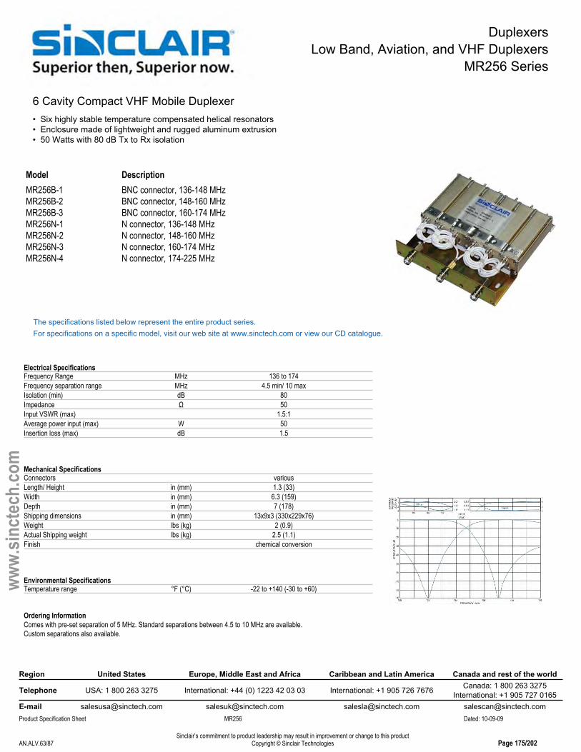
DuplexersLow Band, Aviation, and VHF Duplexers
MR256 Series
6 Cavity Compact VHF Mobile Duplexer• Six highly stable temperature compensated helical resonators• Enclosure made of lightweight and rugged aluminum extrusion• 50 Watts with 80 dB Tx to Rx isolation
Model DescriptionMR256B-1 BNC connector, 136-148 MHzMR256B-2 BNC connector, 148-160 MHzMR256B-3 BNC connector, 160-174 MHzMR256N-1 N connector, 136-148 MHzMR256N-2 N connector, 148-160 MHzMR256N-3 N connector, 160-174 MHzMR256N-4 N connector, 174-225 MHz
The specifications listed below represent the entire product series.For specifications on a specific model, visit our web site at www.sinctech.com or view our CD catalogue.
Electrical SpecificationsFrequency Range MHz 136 to 174Frequency separation range MHz 4.5 min/ 10 maxIsolation (min) dB 80Impedance Ω 50Input VSWR (max) 1.5:1Average power input (max) W 50Insertion loss (max) dB 1.5
Mechanical SpecificationsConnectors variousLength/ Height in (mm) 1.3 (33)Width in (mm) 6.3 (159)Depth in (mm) 7 (178)Shipping dimensions in (mm) 13x9x3 (330x229x76)Weight lbs (kg) 2 (0.9)Actual Shipping weight lbs (kg) 2.5 (1.1)Finish chemical conversion
Environmental SpecificationsTemperature range °F (°C) -22 to +140 (-30 to +60)
Ordering InformationComes with pre-set separation of 5 MHz. Standard separations between 4.5 to 10 MHz are available.Custom separations also available.
Region United States Europe, Middle East and Africa Caribbean and Latin America Canada and rest of the world
Telephone USA: 1 800 263 3275 International: +44 (0) 1223 42 03 03 International: +1 905 726 7676 Canada: 1 800 263 3275International: +1 905 727 0165
E-mail [email protected] [email protected] [email protected] [email protected] Specification Sheet MR256 Dated: 10-09-09
Sinclair’s commitment to product leadership may result in improvement or change to this productCopyright © Sinclair TechnologiesAN.ALV.63/87 Page 175/202
www.
sinct
ech.
com

DuplexersLow Band, Aviation, and VHF Duplexers
P201 Series
4 Cavity High Selectivity Bandpass Duplexer• Easily field-tunable with rotatable loops for selectivity settings• Available in rack-mounted or cabinet configurations• Extremely small frequency drift - typically 0.5 ppm/degree C
Model DescriptionP201GR-1 132-150 MHzP201GR-2 148-174 MHz
The specifications listed below represent the entire product series.For specifications on a specific model, visit our web site at www.sinctech.com or view our CD catalogue.
Electrical SpecificationsFrequency Range MHz 132 to 174Isolation (min) dB 55Impedance Ω 50Input VSWR (max) 1.5:1Average power input (max) W 400Frequency separation MHz 3Insertion loss (max) dB 1.2
Mechanical SpecificationsConnectors N (female)Length/ Height in (mm) 33 (838)Width in (mm) 19 (483)Depth in (mm) 15 (381)Shipping dimensions in (mm) 20x19x38 (508x483x965)Weight lbs (kg) 55 (25)Actual Shipping weight lbs (kg) 60 (27.2)Finish chemical conversion
Environmental SpecificationsTemperature range °F (°C) -40 to +140 (-40 to +60)
Region United States Europe, Middle East and Africa Caribbean and Latin America Canada and rest of the world
Telephone USA: 1 800 263 3275 International: +44 (0) 1223 42 03 03 International: +1 905 726 7676 Canada: 1 800 263 3275International: +1 905 727 0165
E-mail [email protected] [email protected] [email protected] [email protected] Specification Sheet P201 Dated: 10-09-09
Sinclair’s commitment to product leadership may result in improvement or change to this productCopyright © Sinclair TechnologiesAN.ALV.64/87 Page 176/202
www.
sinct
ech.
com
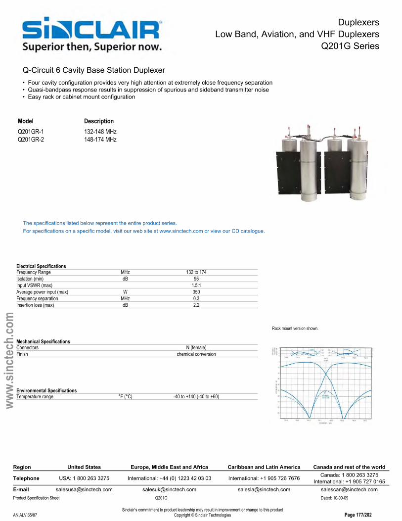
DuplexersLow Band, Aviation, and VHF Duplexers
Q201G Series
Q-Circuit 6 Cavity Base Station Duplexer• Four cavity configuration provides very high attention at extremely close frequency separation• Quasi-bandpass response results in suppression of spurious and sideband transmitter noise• Easy rack or cabinet mount configuration
Rack mount version shown.
Model DescriptionQ201GR-1 132-148 MHzQ201GR-2 148-174 MHz
The specifications listed below represent the entire product series.For specifications on a specific model, visit our web site at www.sinctech.com or view our CD catalogue.
Electrical SpecificationsFrequency Range MHz 132 to 174Isolation (min) dB 95Input VSWR (max) 1.5:1Average power input (max) W 350Frequency separation MHz 0.3Insertion loss (max) dB 2.2
Mechanical SpecificationsConnectors N (female)Finish chemical conversion
Environmental SpecificationsTemperature range °F (°C) -40 to +140 (-40 to +60)
Region United States Europe, Middle East and Africa Caribbean and Latin America Canada and rest of the world
Telephone USA: 1 800 263 3275 International: +44 (0) 1223 42 03 03 International: +1 905 726 7676 Canada: 1 800 263 3275International: +1 905 727 0165
E-mail [email protected] [email protected] [email protected] [email protected] Specification Sheet Q201G Dated: 10-09-09
Sinclair’s commitment to product leadership may result in improvement or change to this productCopyright © Sinclair TechnologiesAN.ALV.65/87 Page 177/202
www.
sinct
ech.
com

DuplexersLow Band, Aviation, and VHF Duplexers
Q202G Series
Four Cavity Q-Circuit Base Station Duplexer • Four cavity configuration provides very high attention at extremely close frequency separation• Quasi-bandpass response results in suppression of spurious and sideband transmitter noise• Easy cabinet mount configuration
Model DescriptionQ202GC-1 132-148 MHz, N connector, stand alone cabinetQ202GC-2 148- 174 MHz, N connector, stand alone cabinetQ202GC-UHF-1 138-148 MHz, UHF connector, stand alone cabinetQ202GC-UHF-2 148-174 MHz, UHF connector, stand alone cabinetQ202GR-1 132-148 MHz, N connector, rack mountQ202GR-2 148-174 MHz, N connector, rack mount
The specifications listed below represent the entire product series.For specifications on a specific model, visit our web site at www.sinctech.com or view our CD catalogue.
Electrical SpecificationsFrequency Range MHz 132 to 174Isolation (min) dB 80Impedance Ω 50Input VSWR (max) 1.5:1Average power input (max) W 350Frequency separation (min) MHz 0.5Insertion loss (max) dB 1.5
Mechanical SpecificationsConnectors N (female)Length/ Height in (mm) 40.4 (1026)Width in (mm) 18 (457)Depth in (mm) 22 (559)Shipping dimensions in (mm) 22x22x43 (559x559x1092)Weight lbs (kg) 132 (59.9)Actual Shipping weight lbs (kg) 75 (34.1)Finish chemical conversion
Environmental SpecificationsTemperature range °F (°C) -22 to +140 (-30 to +60)
Region United States Europe, Middle East and Africa Caribbean and Latin America Canada and rest of the world
Telephone USA: 1 800 263 3275 International: +44 (0) 1223 42 03 03 International: +1 905 726 7676 Canada: 1 800 263 3275International: +1 905 727 0165
E-mail [email protected] [email protected] [email protected] [email protected] Specification Sheet Q202G Dated: 10-09-09
Sinclair’s commitment to product leadership may result in improvement or change to this productCopyright © Sinclair TechnologiesAN.ALV.66/87 Page 178/202
www.
sinct
ech.
com
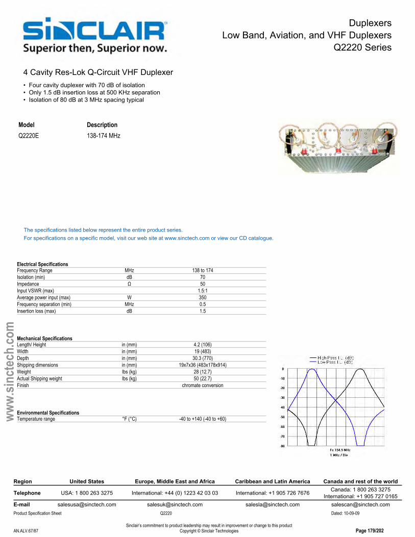
DuplexersLow Band, Aviation, and VHF Duplexers
Q2220 Series
4 Cavity Res-Lok Q-Circuit VHF Duplexer• Four cavity duplexer with 70 dB of isolation• Only 1.5 dB insertion loss at 500 KHz separation• Isolation of 80 dB at 3 MHz spacing typical
Model DescriptionQ2220E 138-174 MHz
The specifications listed below represent the entire product series.For specifications on a specific model, visit our web site at www.sinctech.com or view our CD catalogue.
Electrical SpecificationsFrequency Range MHz 138 to 174Isolation (min) dB 70Impedance Ω 50Input VSWR (max) 1.5:1Average power input (max) W 350Frequency separation (min) MHz 0.5Insertion loss (max) dB 1.5
Mechanical SpecificationsLength/ Height in (mm) 4.2 (106)Width in (mm) 19 (483)Depth in (mm) 30.3 (770)Shipping dimensions in (mm) 19x7x36 (483x178x914)Weight lbs (kg) 28 (12.7)Actual Shipping weight lbs (kg) 50 (22.7)Finish chromate conversion
Environmental SpecificationsTemperature range °F (°C) -40 to +140 (-40 to +60)
Region United States Europe, Middle East and Africa Caribbean and Latin America Canada and rest of the world
Telephone USA: 1 800 263 3275 International: +44 (0) 1223 42 03 03 International: +1 905 726 7676 Canada: 1 800 263 3275International: +1 905 727 0165
E-mail [email protected] [email protected] [email protected] [email protected] Specification Sheet Q2220 Dated: 10-09-09
Sinclair’s commitment to product leadership may result in improvement or change to this productCopyright © Sinclair TechnologiesAN.ALV.67/87 Page 179/202
www.
sinct
ech.
com
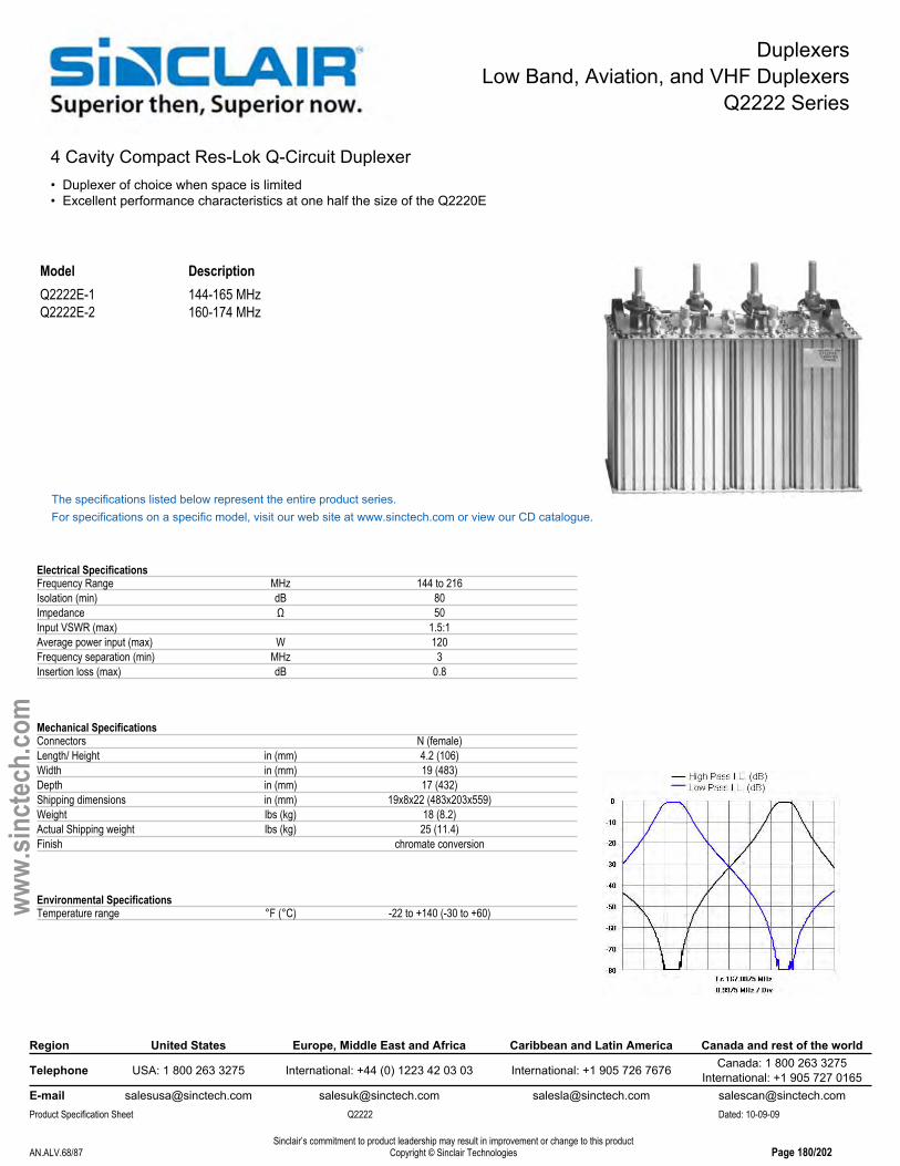
DuplexersLow Band, Aviation, and VHF Duplexers
Q2222 Series
4 Cavity Compact Res-Lok Q-Circuit Duplexer• Duplexer of choice when space is limited• Excellent performance characteristics at one half the size of the Q2220E
Model DescriptionQ2222E-1 144-165 MHzQ2222E-2 160-174 MHz
The specifications listed below represent the entire product series.For specifications on a specific model, visit our web site at www.sinctech.com or view our CD catalogue.
Electrical SpecificationsFrequency Range MHz 144 to 216Isolation (min) dB 80Impedance Ω 50Input VSWR (max) 1.5:1Average power input (max) W 120Frequency separation (min) MHz 3Insertion loss (max) dB 0.8
Mechanical SpecificationsConnectors N (female)Length/ Height in (mm) 4.2 (106)Width in (mm) 19 (483)Depth in (mm) 17 (432)Shipping dimensions in (mm) 19x8x22 (483x203x559)Weight lbs (kg) 18 (8.2)Actual Shipping weight lbs (kg) 25 (11.4)Finish chromate conversion
Environmental SpecificationsTemperature range °F (°C) -22 to +140 (-30 to +60)
Region United States Europe, Middle East and Africa Caribbean and Latin America Canada and rest of the world
Telephone USA: 1 800 263 3275 International: +44 (0) 1223 42 03 03 International: +1 905 726 7676 Canada: 1 800 263 3275International: +1 905 727 0165
E-mail [email protected] [email protected] [email protected] [email protected] Specification Sheet Q2222 Dated: 10-09-09
Sinclair’s commitment to product leadership may result in improvement or change to this productCopyright © Sinclair TechnologiesAN.ALV.68/87 Page 180/202
www.
sinct
ech.
com

DuplexersLow Band, Aviation, and VHF Duplexers
Q2330 Series
6 Cavity Res-Lok Q-Circuit VHF Duplexer• Six-cavity duplexer provides 85 dB isolation• Res-Lok design reduces inter-cavity cabling and losses• Provides up to 85 dB isolation at frequency separation of 500 KHz with 2 dB IL
Model DescriptionQ2330E 138-174 MHz
The specifications listed below represent the entire product series.For specifications on a specific model, visit our web site at www.sinctech.com or view our CD catalogue.
Electrical SpecificationsFrequency Range MHz 138 to 174Isolation (min) dB 85Impedance Ω 50Pass bandwidth MHz 0.5Input VSWR (max) 1.5:1Average power input (max) W 350Frequency separation MHz 0.5Insertion loss (max) dB 1.5
Mechanical SpecificationsConnectors N (female)Length/ Height in (mm) 8.4 (213)Width in (mm) 19 (483)Depth in (mm) 30.3 (770)Shipping dimensions in (mm) 19x7x36 (483x178x914)Weight lbs (kg) 45 (20.4)Actual Shipping weight lbs (kg) 50 (22.7)Finish chromate conversion
Environmental SpecificationsTemperature range °F (°C) -40 to +140 (-40 to +60)
Region United States Europe, Middle East and Africa Caribbean and Latin America Canada and rest of the world
Telephone USA: 1 800 263 3275 International: +44 (0) 1223 42 03 03 International: +1 905 726 7676 Canada: 1 800 263 3275International: +1 905 727 0165
E-mail [email protected] [email protected] [email protected] [email protected] Specification Sheet Q2330 Dated: 10-09-09
Sinclair’s commitment to product leadership may result in improvement or change to this productCopyright © Sinclair TechnologiesAN.ALV.69/87 Page 181/202
www.
sinct
ech.
com
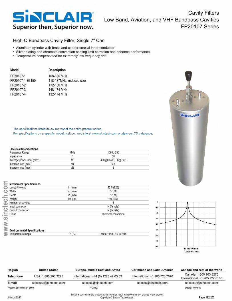
Cavity FiltersLow Band, Aviation, and VHF Bandpass Cavities
FP20107 Series
High-Q Bandpass Cavity Filter, Single 7" Can• Aluminum cylinder with brass and copper coaxial inner conductor• Silver plating and chromate conversion coating limit corrosion and enhance performance• Temperature compensated for extremely low frequency drift
Model DescriptionFP20107-1 108-136 MHzFP20107-1-E3150 118-137MHz, reduced sizeFP20107-2 132-150 MHzFP20107-3 148-174 MHzFP20107-4 132-174 MHz
The specifications listed below represent the entire product series.For specifications on a specific model, visit our web site at www.sinctech.com or view our CD catalogue.
Electrical SpecificationsFrequency Range MHz 108 to 230Impedance Ω 50Average power input (max) W [email protected] dB, 90@ 3dBInsertion loss (min) dB 0.5Insertion loss (max) dB 3
Mechanical SpecificationsLength/ Height in (mm) 32.5 (826)Width in (mm) 7 (178)Depth in (mm) 7 (178)Weight lbs (kg) 10 (4.5)Number of cavities 1Input connector N (female)Output connector N (female)Finish chemical conversion
Environmental SpecificationsTemperature range °F (°C) -40 to +140 (-40 to +60)
Region United States Europe, Middle East and Africa Caribbean and Latin America Canada and rest of the world
Telephone USA: 1 800 263 3275 International: +44 (0) 1223 42 03 03 International: +1 905 726 7676 Canada: 1 800 263 3275International: +1 905 727 0165
E-mail [email protected] [email protected] [email protected] [email protected] Specification Sheet FP20107 Dated: 10-09-09
Sinclair’s commitment to product leadership may result in improvement or change to this productCopyright © Sinclair TechnologiesAN.ALV.70/87 Page 182/202
www.
sinct
ech.
com
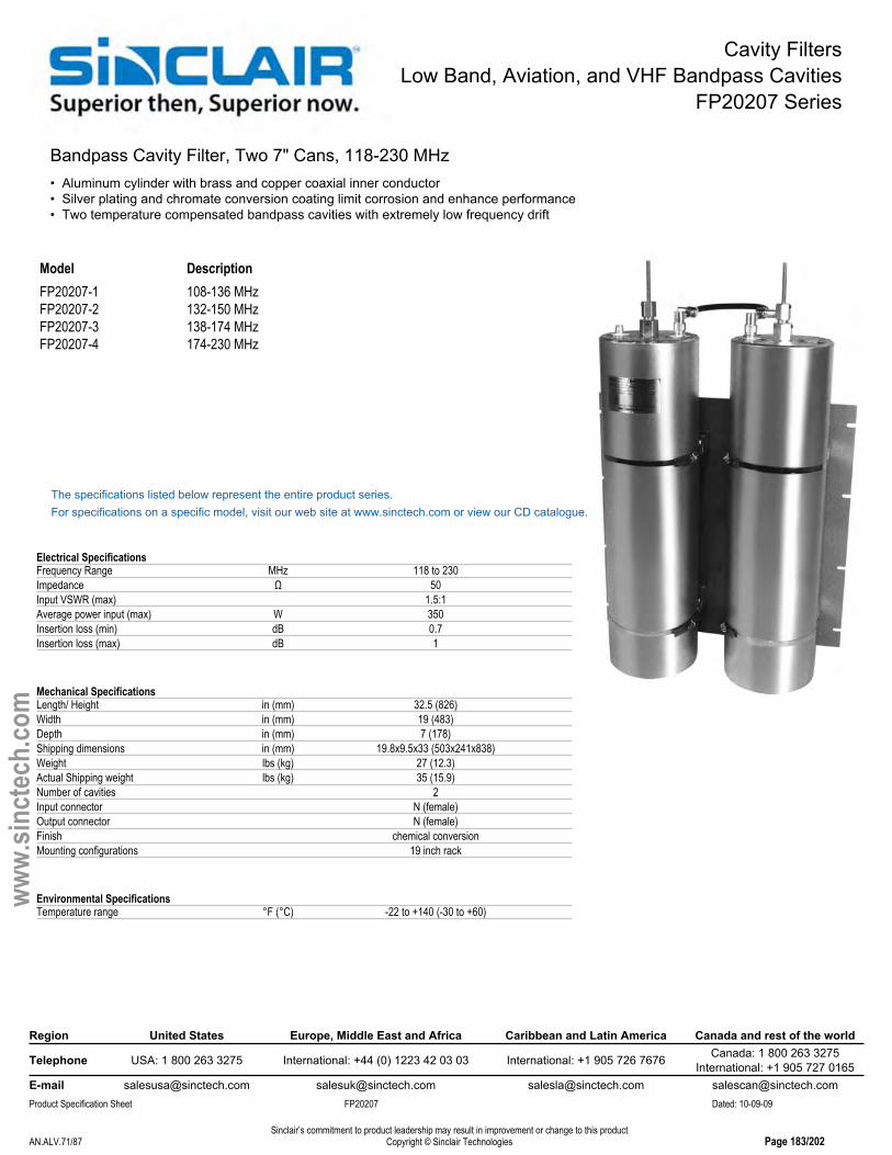
Cavity FiltersLow Band, Aviation, and VHF Bandpass Cavities
FP20207 Series
Bandpass Cavity Filter, Two 7" Cans, 118-230 MHz• Aluminum cylinder with brass and copper coaxial inner conductor• Silver plating and chromate conversion coating limit corrosion and enhance performance• Two temperature compensated bandpass cavities with extremely low frequency drift
Model DescriptionFP20207-1 108-136 MHzFP20207-2 132-150 MHzFP20207-3 138-174 MHzFP20207-4 174-230 MHz
The specifications listed below represent the entire product series.For specifications on a specific model, visit our web site at www.sinctech.com or view our CD catalogue.
Electrical SpecificationsFrequency Range MHz 118 to 230Impedance Ω 50Input VSWR (max) 1.5:1Average power input (max) W 350Insertion loss (min) dB 0.7Insertion loss (max) dB 1
Mechanical SpecificationsLength/ Height in (mm) 32.5 (826)Width in (mm) 19 (483)Depth in (mm) 7 (178)Shipping dimensions in (mm) 19.8x9.5x33 (503x241x838)Weight lbs (kg) 27 (12.3)Actual Shipping weight lbs (kg) 35 (15.9)Number of cavities 2Input connector N (female)Output connector N (female)Finish chemical conversionMounting configurations 19 inch rack
Environmental SpecificationsTemperature range °F (°C) -22 to +140 (-30 to +60)
Region United States Europe, Middle East and Africa Caribbean and Latin America Canada and rest of the world
Telephone USA: 1 800 263 3275 International: +44 (0) 1223 42 03 03 International: +1 905 726 7676 Canada: 1 800 263 3275International: +1 905 727 0165
E-mail [email protected] [email protected] [email protected] [email protected] Specification Sheet FP20207 Dated: 10-09-09
Sinclair’s commitment to product leadership may result in improvement or change to this productCopyright © Sinclair TechnologiesAN.ALV.71/87 Page 183/202
www.
sinct
ech.
com

Cavity FiltersLow Band, Aviation, and VHF Q-Circuit Cavities
FQ20107 Series
Q Circuit Cavity Filter, Single 7" Can• Aluminum cylinder with brass and copper coaxial inner conductor• Silver plating and chromate conversion coating limit corrosion and enhance performance• Temperature compensated for extremely low frequency drift
Model DescriptionFQ20107-1 118-132 MHzFQ20107-2 132-150 MHzFQ20107-3 150-174 MHz
The specifications listed below represent the entire product series.For specifications on a specific model, visit our web site at www.sinctech.com or view our CD catalogue.
Electrical SpecificationsFrequency Range MHz 118 to 174Impedance Ω 50Input VSWR (max) 1.5:1Average power input (max) W 350
Mechanical SpecificationsWidth in (mm) 7 (178)Depth in (mm) 7 (178)Shipping dimensions in (mm) 36x9x9 (914x229x229)Actual Shipping weight lbs (kg) 10 (4.5)Number of cavities 1Input connector N (female)Output connector N (female)
Environmental SpecificationsTemperature range °F (°C) -40 to +140 (-40 to +60)
Region United States Europe, Middle East and Africa Caribbean and Latin America Canada and rest of the world
Telephone USA: 1 800 263 3275 International: +44 (0) 1223 42 03 03 International: +1 905 726 7676 Canada: 1 800 263 3275International: +1 905 727 0165
E-mail [email protected] [email protected] [email protected] [email protected] Specification Sheet FQ20107 Dated: 10-09-09
Sinclair’s commitment to product leadership may result in improvement or change to this productCopyright © Sinclair TechnologiesAN.ALV.72/87 Page 184/202
www.
sinct
ech.
com
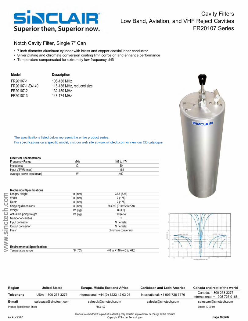
Cavity FiltersLow Band, Aviation, and VHF Reject Cavities
FR20107 Series
Notch Cavity Filter, Single 7" Can• 7 inch diameter aluminum cylinder with brass and copper coaxial inner conductor• Silver plating and chromate conversion coating limit corrosion and enhance performance• Temperature compensated for extremely low frequency drift
Model DescriptionFR20107-1 108-136 MHzFR20107-1-E4149 118-136 MHz, reduced sizeFR20107-2 132-150 MHzFR20107-3 148-174 MHz
The specifications listed below represent the entire product series.For specifications on a specific model, visit our web site at www.sinctech.com or view our CD catalogue.
Electrical SpecificationsFrequency Range MHz 108 to 174Impedance Ω 50Input VSWR (max) 1.5:1Average power input (max) W 400
Mechanical SpecificationsLength/ Height in (mm) 32.5 (826)Width in (mm) 7 (178)Depth in (mm) 7 (178)Shipping dimensions in (mm) 36x9x9 (914x229x229)Weight lbs (kg) 8 (3.6)Actual Shipping weight lbs (kg) 10 (4.5)Number of cavities 1Input connector N (female)Output connector N (female)Finish chromate conversion
Environmental SpecificationsTemperature range °F (°C) -40 to +140 (-40 to +60)
Region United States Europe, Middle East and Africa Caribbean and Latin America Canada and rest of the world
Telephone USA: 1 800 263 3275 International: +44 (0) 1223 42 03 03 International: +1 905 726 7676 Canada: 1 800 263 3275International: +1 905 727 0165
E-mail [email protected] [email protected] [email protected] [email protected] Specification Sheet FR20107 Dated: 10-09-09
Sinclair’s commitment to product leadership may result in improvement or change to this productCopyright © Sinclair TechnologiesAN.ALV.73/87 Page 185/202
www.
sinct
ech.
com
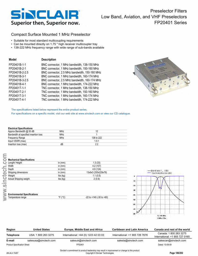
Preselector FiltersLow Band, Aviation, and VHF Preselectors
FP20401 Series
Compact Surface Mounted 1 MHz Preselector• Suitable for most standard multicoupling requirements• Can be mounted directly on 1.75 " high receiver multicoupler tray• 138-222 MHz frequency range with wide range of sub-bands available
Model DescriptionFP20401B-1-1 BNC connector, 1 MHz bandwidth, 138-150 MHzFP20401B-2-1 BNC connector, 1 MHz bandwidth, 150-160 MHzFP20401B-2-2.5 BNC connector, 2.5 MHz bandwidth, 150-160 MHzFP20401B-3-1 BNC connector, 1 MHz bandwidth, 160-174 MHzFP20401B-3-2.5 BNC connector, 2.5 MHz bandwidth, 160-174 MHzFP20401B-4-1 BNC connector, 1 MHz bandwidth, 174-222 MHzFP20401T-1-1 TNC connector, 1 MHz bandwidth, 138-150 MHzFP20401T-2-1 TNC connector, 1 MHz bandwidth, 150-160 MHzFP20401T-3-1 TNC connector, 1 MHz bandwidth, 160-174 MHzFP20401T-4-1 TNC connector, 1 MHz bandwidth, 174-222 MHz
The specifications listed below represent the entire product series.For specifications on a specific model, visit our web site at www.sinctech.com or view our CD catalogue.
Electrical SpecificationsApprox Bandwidth @ 50 dB MHz 12Bandwidth at specified insertion loss MHz 1Frequency Range MHz 138 to 222Input VSWR (max) 1.5:1Insertion loss (max) dB 2.2
Mechanical SpecificationsLength/ Height in (mm) 1.3 (33)Width in (mm) 4.2 (107)Depth in (mm) 4.9 (124)Shipping dimensions in (mm) 13x9x3 (330x229x76)Weight lbs (kg) 1.1 (0.5)Actual Shipping weight lbs (kg) 2 (0.9)
Environmental SpecificationsTemperature range °F (°C) -22 to +140 (-30 to +60)
Region United States Europe, Middle East and Africa Caribbean and Latin America Canada and rest of the world
Telephone USA: 1 800 263 3275 International: +44 (0) 1223 42 03 03 International: +1 905 726 7676 Canada: 1 800 263 3275International: +1 905 727 0165
E-mail [email protected] [email protected] [email protected] [email protected] Specification Sheet FP20401 Dated: 10-09-09
Sinclair’s commitment to product leadership may result in improvement or change to this productCopyright © Sinclair TechnologiesAN.ALV.74/87 Page 186/202
www.
sinct
ech.
com

Preselector FiltersLow Band, Aviation, and VHF Preselectors
FP20402 Series
Preselector, UHF 130-170MHz, High Performance, N Male• Extremely high selectivity, high performance design• Very compact, low profile VHF preselector for 130-170MHz• Easy to tune with very high temperature stability
Model DescriptionFP20402N-1-0.5 0.5 MHz BW, N-Female connector, 130-150 MHzFP20402N-1-1 1 MHz BW, N-female connector, 130-150 MHzFP20402N-1-2 2 MHZ BW, N-female connector, 130-150 MHzFP20402N-2-0.5 0.5 MHz BW, N-female connector, 150-170 MHzFP20402N-2-1 1 MHz BW, N-female connector, 150-170 MHzFP20402N-2-2 2 MHZ BW, N-Female connector, 150-170MHz
The specifications listed below represent the entire product series.For specifications on a specific model, visit our web site at www.sinctech.com or view our CD catalogue.
Electrical SpecificationsApprox Bandwidth @ 50 dB MHz 5.5Frequency Range MHz 130 to 174Input VSWR (max) 1.5:1Insertion loss (max) dB 2
Mechanical SpecificationsLength/ Height in (mm) 3.5 (89)Width in (mm) 19 (483)Depth in (mm) 17 (432)Weight lbs (kg) 9 (4.1)Number of cavities 4Input connector N (female)Output connector N (female)Mounting configurations 19 inch rack
Environmental SpecificationsTemperature range °F (°C) -22 to +140 (-30 to +60)
Region United States Europe, Middle East and Africa Caribbean and Latin America Canada and rest of the world
Telephone USA: 1 800 263 3275 International: +44 (0) 1223 42 03 03 International: +1 905 726 7676 Canada: 1 800 263 3275International: +1 905 727 0165
E-mail [email protected] [email protected] [email protected] [email protected] Specification Sheet FP20402 Dated: 10-09-09
Sinclair’s commitment to product leadership may result in improvement or change to this productCopyright © Sinclair TechnologiesAN.ALV.75/87 Page 187/202
www.
sinct
ech.
com

Preselector FiltersLow Band, Aviation, and VHF Preselectors
PH2040 Series
Highly Versatile Res-Lok 1 or 2 MHz Preselector• Rack, wall and floor mounting options - can also be used as transmitter filter• Res-Lok construction reduces inter-cavity cabling• Covers the 137-174 MHz frequency band
Model DescriptionPH2040E-1 1 MHz BW, 138-174 MHzPH2040E-2 2 MHz BW, 138-174 MHz
The specifications listed below represent the entire product series.For specifications on a specific model, visit our web site at www.sinctech.com or view our CD catalogue.
Electrical SpecificationsBandwidth at specified insertion loss MHz 1Frequency Range MHz 137 to 174Input VSWR (max) 1.5:1Average power input (max) W 400
Mechanical SpecificationsLength/ Height in (mm) 31.5 (800)Width in (mm) 19 (483)Depth in (mm) 4.3 (109)Shipping dimensions in (mm) 19x7x38 (483x178x965)Weight lbs (kg) 26 (11.8)Actual Shipping weight lbs (kg) 50 (22.7)Input connector N (female)Output connector N (female)Mounting configurations 19 inch rack
Environmental SpecificationsTemperature range °F (°C) -22 to +140 (-30 to +60)
Region United States Europe, Middle East and Africa Caribbean and Latin America Canada and rest of the world
Telephone USA: 1 800 263 3275 International: +44 (0) 1223 42 03 03 International: +1 905 726 7676 Canada: 1 800 263 3275International: +1 905 727 0165
E-mail [email protected] [email protected] [email protected] [email protected] Specification Sheet PH2040 Dated: 10-09-09
Sinclair’s commitment to product leadership may result in improvement or change to this productCopyright © Sinclair TechnologiesAN.ALV.76/87 Page 188/202
www.
sinct
ech.
com

Expandable MulticouplersLow Band, Aviation, and VHF Exp. Multicouplers
C2017P Series
C Series Pass-Thru Expandable Multicoupler, 7" Cans• One FP bandpass and one FS pass-through cavity filter• More cost effective solution for installations undergoing very few frequency changes• Supports 75 KHz spacings with 2.5 to 2.8 dB insertion loss (no isolator)
Model DescriptionC2017P-3 148-174 MHz
The specifications listed below represent the entire product series.For specifications on a specific model, visit our web site at www.sinctech.com or view our CD catalogue.
Electrical SpecificationsFrequency Range MHz 132 to 174Input VSWR (max) 1.5:1Frequency separation (min) MHz 0.08
Mechanical SpecificationsNet Weight lbs (kg) 31 (14.1)Length/ Height in (mm) 32.5 (826)Width in (mm) 19 (483)Depth in (mm) 7.5 (191)Shipping dimensions in (mm) 10x20x34 (254x508x864)Actual Shipping weight lbs (kg) 40 (18.2)Input connector N (female)Output connector N (female)
Environmental SpecificationsTemperature range °F (°C) -40 to +140 (-40 to +60)
Ordering InformationChart insertion losses are nominal settings and do not include bridging losses and losses due to the inclusion of other equipment.
Region United States Europe, Middle East and Africa Caribbean and Latin America Canada and rest of the world
Telephone USA: 1 800 263 3275 International: +44 (0) 1223 42 03 03 International: +1 905 726 7676 Canada: 1 800 263 3275International: +1 905 727 0165
E-mail [email protected] [email protected] [email protected] [email protected] Specification Sheet C2017P Dated: 10-09-09
Sinclair’s commitment to product leadership may result in improvement or change to this productCopyright © Sinclair TechnologiesAN.ALV.77/87 Page 189/202
www.
sinct
ech.
com
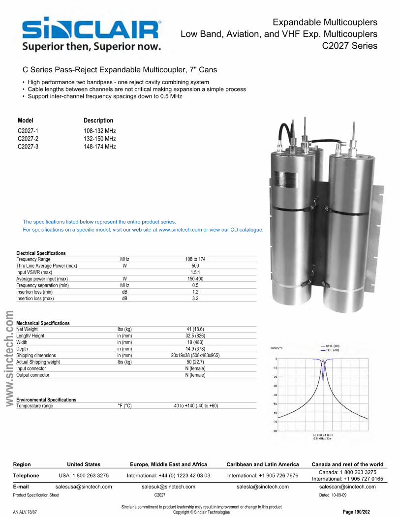
Expandable MulticouplersLow Band, Aviation, and VHF Exp. Multicouplers
C2027 Series
C Series Pass-Reject Expandable Multicoupler, 7" Cans• High performance two bandpass - one reject cavity combining system• Cable lengths between channels are not critical making expansion a simple process• Support inter-channel frequency spacings down to 0.5 MHz
Model DescriptionC2027-1 108-132 MHzC2027-2 132-150 MHzC2027-3 148-174 MHz
The specifications listed below represent the entire product series.For specifications on a specific model, visit our web site at www.sinctech.com or view our CD catalogue.
Electrical SpecificationsFrequency Range MHz 108 to 174Thru Line Average Power (max) W 500Input VSWR (max) 1.5:1Average power input (max) W 150-400Frequency separation (min) MHz 0.5Insertion loss (min) dB 1.2Insertion loss (max) dB 3.2
Mechanical SpecificationsNet Weight lbs (kg) 41 (18.6)Length/ Height in (mm) 32.5 (826)Width in (mm) 19 (483)Depth in (mm) 14.9 (378)Shipping dimensions in (mm) 20x19x38 (508x483x965)Actual Shipping weight lbs (kg) 50 (22.7)Input connector N (female)Output connector N (female)
Environmental SpecificationsTemperature range °F (°C) -40 to +140 (-40 to +60)
Region United States Europe, Middle East and Africa Caribbean and Latin America Canada and rest of the world
Telephone USA: 1 800 263 3275 International: +44 (0) 1223 42 03 03 International: +1 905 726 7676 Canada: 1 800 263 3275International: +1 905 727 0165
E-mail [email protected] [email protected] [email protected] [email protected] Specification Sheet C2027 Dated: 10-09-09
Sinclair’s commitment to product leadership may result in improvement or change to this productCopyright © Sinclair TechnologiesAN.ALV.78/87 Page 190/202
www.
sinct
ech.
com
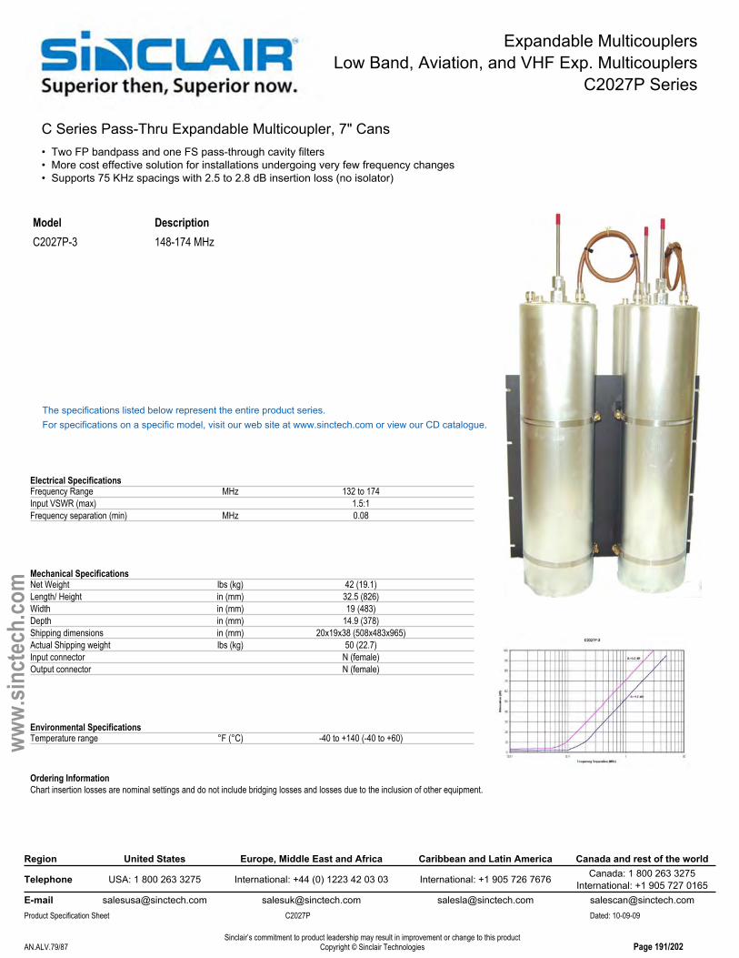
Expandable MulticouplersLow Band, Aviation, and VHF Exp. Multicouplers
C2027P Series
C Series Pass-Thru Expandable Multicoupler, 7" Cans• Two FP bandpass and one FS pass-through cavity filters• More cost effective solution for installations undergoing very few frequency changes• Supports 75 KHz spacings with 2.5 to 2.8 dB insertion loss (no isolator)
Model DescriptionC2027P-3 148-174 MHz
The specifications listed below represent the entire product series.For specifications on a specific model, visit our web site at www.sinctech.com or view our CD catalogue.
Electrical SpecificationsFrequency Range MHz 132 to 174Input VSWR (max) 1.5:1Frequency separation (min) MHz 0.08
Mechanical SpecificationsNet Weight lbs (kg) 42 (19.1)Length/ Height in (mm) 32.5 (826)Width in (mm) 19 (483)Depth in (mm) 14.9 (378)Shipping dimensions in (mm) 20x19x38 (508x483x965)Actual Shipping weight lbs (kg) 50 (22.7)Input connector N (female)Output connector N (female)
Environmental SpecificationsTemperature range °F (°C) -40 to +140 (-40 to +60)
Ordering InformationChart insertion losses are nominal settings and do not include bridging losses and losses due to the inclusion of other equipment.
Region United States Europe, Middle East and Africa Caribbean and Latin America Canada and rest of the world
Telephone USA: 1 800 263 3275 International: +44 (0) 1223 42 03 03 International: +1 905 726 7676 Canada: 1 800 263 3275International: +1 905 727 0165
E-mail [email protected] [email protected] [email protected] [email protected] Specification Sheet C2027P Dated: 10-09-09
Sinclair’s commitment to product leadership may result in improvement or change to this productCopyright © Sinclair TechnologiesAN.ALV.79/87 Page 191/202
www.
sinct
ech.
com

Expandable MulticouplersLow Band, Aviation, and VHF Exp. Multicouplers
C2034 Series
Res-Lok Pass-Reject Expandable Multicoupler, 118-174 MHz• Compact high-performance three bandpass and one reject cavity multicoupling system• Cable lengths between channels are not critical making expansion a simple process• Support inter-channel frequency spacings down to 1 MHz
Model DescriptionC2034-1-1.6 118-136 MHz, 1.6 dB ILC2034-1-3.1 118-136 MHz, 3.1 dB ILC2034-2-1.6 136-155 MHz, 1.6 dB ILC2034-2-3.1 136-155 MHz, 3.1 dB ILC2034-3-1.6 155-174 MHz, 1.6 dB ILC2034-3-3.1 155-174 MHz, 3.1 dB IL
The specifications listed below represent the entire product series.For specifications on a specific model, visit our web site at www.sinctech.com or view our CD catalogue.
Electrical SpecificationsFrequency Range MHz 118 to 174Thru Line Average Power (max) W 1300Input VSWR (max) 1.5:1Average power input (max) W 210-400Frequency separation (min) MHz 1
Mechanical SpecificationsNet Weight lbs (kg) 36 (16.3)Length/ Height in (mm) 38 (965)Width in (mm) 19 (483)Depth in (mm) 4.2 (106)Shipping dimensions in (mm) 19x7x42 (483x178x1067)Actual Shipping weight lbs (kg) 50 (22.7)Input connector N (female)Output connector N (female)
Environmental SpecificationsTemperature range °F (°C) -40 to +140 (-40 to +60)
Region United States Europe, Middle East and Africa Caribbean and Latin America Canada and rest of the world
Telephone USA: 1 800 263 3275 International: +44 (0) 1223 42 03 03 International: +1 905 726 7676 Canada: 1 800 263 3275International: +1 905 727 0165
E-mail [email protected] [email protected] [email protected] [email protected] Specification Sheet C2034 Dated: 10-09-09
Sinclair’s commitment to product leadership may result in improvement or change to this productCopyright © Sinclair TechnologiesAN.ALV.80/87 Page 192/202
www.
sinct
ech.
com
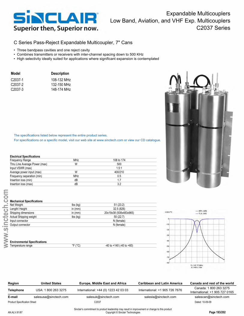
Expandable MulticouplersLow Band, Aviation, and VHF Exp. Multicouplers
C2037 Series
C Series Pass-Reject Expandable Multicoupler, 7" Cans• Three bandpass cavities and one reject cavity• Combines transmitters or receivers with inter-channel spacing down to 500 KHz• High selectivity ideally suited for applications where significant expansion is contemplated
Model DescriptionC2037-1 108-132 MHzC2037-2 132-150 MHzC2037-3 148-174 MHz
The specifications listed below represent the entire product series.For specifications on a specific model, visit our web site at www.sinctech.com or view our CD catalogue.
Electrical SpecificationsFrequency Range MHz 108 to 174Thru Line Average Power (max) W 500Input VSWR (max) 1.5:1Average power input (max) W 400/210Frequency separation (min) MHz 0.5Insertion loss (min) dB 1.7Insertion loss (max) dB 3.2
Mechanical SpecificationsNet Weight lbs (kg) 51 (23.2)Length/ Height in (mm) 32.5 (826)Shipping dimensions in (mm) 20x19x38 (508x483x965)Actual Shipping weight lbs (kg) 50 (22.7)Input connector N (female)Output connector N (female)
Environmental SpecificationsTemperature range °F (°C) -40 to +140 (-40 to +60)
Region United States Europe, Middle East and Africa Caribbean and Latin America Canada and rest of the world
Telephone USA: 1 800 263 3275 International: +44 (0) 1223 42 03 03 International: +1 905 726 7676 Canada: 1 800 263 3275International: +1 905 727 0165
E-mail [email protected] [email protected] [email protected] [email protected] Specification Sheet C2037 Dated: 10-09-09
Sinclair’s commitment to product leadership may result in improvement or change to this productCopyright © Sinclair TechnologiesAN.ALV.81/87 Page 193/202
www.
sinct
ech.
com

Hybrid CouplersLow Band, Aviation, and VHF Hybrid Couplers
HH1 Series
Hybrid Coupler, 66-100 MHz• Rugged N female / N male design• Max insertion loss of 3.3 dB per port• VSWR less than 1.25 for T1 to T2 ports
Note: Picture shown is an HH-2140
Model DescriptionHH1140 66-100 MHz
The specifications listed below represent the entire product series.For specifications on a specific model, visit our web site at www.sinctech.com or view our CD catalogue.
Electrical SpecificationsFrequency Range MHz 66 to 100Isolation (min) dB 45VSWR 1.25:1Power Rating W 350Insertion loss (max) dB 3.3
Mechanical SpecificationsConnectors N-male and N-femaleLength/ Height in (mm) 1.2 (30)Width in (mm) 14 (356)Depth in (mm) 1.4 (36)Shipping dimensions in (mm) 26x6x4 (660x152x102)Actual Shipping weight lbs (kg) 3 (1.4)
Environmental SpecificationsTemperature range °F (°C) -22 to +140 (-30 to +60)
Ordering InformationT1 to T2 inputs N Male- Load and antenna termination N Female.Specify operating frequencies.HH-1140 specs shown at series level.
Region United States Europe, Middle East and Africa Caribbean and Latin America Canada and rest of the world
Telephone USA: 1 800 263 3275 International: +44 (0) 1223 42 03 03 International: +1 905 726 7676 Canada: 1 800 263 3275International: +1 905 727 0165
E-mail [email protected] [email protected] [email protected] [email protected] Specification Sheet HH1 Dated: 10-09-09
Sinclair’s commitment to product leadership may result in improvement or change to this productCopyright © Sinclair TechnologiesAN.ALV.82/87 Page 194/202
www.
sinct
ech.
com

Hybrid CouplersLow Band, Aviation, and VHF Hybrid Couplers
HH2 Series
Hybrid Coupler, 132-174 Band• Rugged N Female / N Male design• Max insertion loss of 3.3 dB per port• VSWR less than 1.25 for T1 to T2 ports
Note: HH2140 shown
Model DescriptionHH2140 132-174 MHz
The specifications listed below represent the entire product series.For specifications on a specific model, visit our web site at www.sinctech.com or view our CD catalogue.
Electrical SpecificationsFrequency Range MHz 132 to 174Isolation (min) dB 45VSWR 1.25:1Power Rating W 350Insertion loss (max) dB 3.3
Mechanical SpecificationsConnectors N-male and N-femaleLength/ Height in (mm) 1.2 (30)Width in (mm) 16 (406)Depth in (mm) 1.4 (36)Shipping dimensions in (mm) 26x4x6 (660x102x152)Actual Shipping weight lbs (kg) 3 (1.4)
Environmental SpecificationsTemperature range °F (°C) -22 to +140 (-30 to +60)
Ordering InformationT1 to T2 inputs N Male- Load and antenna termination N Female.Specify operating frequencies.HH-2140 specs shown at series level.
Region United States Europe, Middle East and Africa Caribbean and Latin America Canada and rest of the world
Telephone USA: 1 800 263 3275 International: +44 (0) 1223 42 03 03 International: +1 905 726 7676 Canada: 1 800 263 3275International: +1 905 727 0165
E-mail [email protected] [email protected] [email protected] [email protected] Specification Sheet HH2 Dated: 10-09-09
Sinclair’s commitment to product leadership may result in improvement or change to this productCopyright © Sinclair TechnologiesAN.ALV.83/87 Page 195/202
www.
sinct
ech.
com

Isolators and CirculatorsLow Band, Aviation, and VHF Isolator & Circulators
I1 Series
Compact, rugged Isolator/Circulator, 66-100 MHz • Carefully temperature compensated• Low insertion loss• Highly reliable design with top quality sub-components
Model DescriptionI1110A Circulator, single, 66-100 MHzI1111A Isolator, single, 15 watt load, 66-100 MHzI1113A Isolator, single, 60 watt load, 66-100 MHz
The specifications listed below represent the entire product series.For specifications on a specific model, visit our web site at www.sinctech.com or view our CD catalogue.
Electrical SpecificationsBandwidth MHz 2Frequency Range MHz 60 to 100Isolation (min) dB 25VSWR 1.25:1Power Input W 100Insertion loss (typ) dB 0.7Insertion loss (max) dB 1Isolation (typ) dB 35
Mechanical SpecificationsConnectors N (female)Length/ Height in (mm) 3 (76)Width in (mm) 3 (76)Depth in (mm) 1.4 (36)Shipping dimensions in (mm) 13x9x3 (330x229x76)Actual Shipping weight lbs (kg) 2.5 (1.1)
Environmental SpecificationsTemperature range °F (°C) -22 to +140 (-30 to +60)
Region United States Europe, Middle East and Africa Caribbean and Latin America Canada and rest of the world
Telephone USA: 1 800 263 3275 International: +44 (0) 1223 42 03 03 International: +1 905 726 7676 Canada: 1 800 263 3275International: +1 905 727 0165
E-mail [email protected] [email protected] [email protected] [email protected] Specification Sheet I1 Dated: 10-09-09
Sinclair’s commitment to product leadership may result in improvement or change to this productCopyright © Sinclair TechnologiesAN.ALV.84/87 Page 196/202
www.
sinct
ech.
com

Isolators and CirculatorsLow Band, Aviation, and VHF Isolator & Circulators
I2 Series
Compact Rugged Isolator/Circulator, 132-174 MHz• Carefully temperature compensated• Low insertion loss• Highly reliable design with top quality sub-components
Model DescriptionI2110A Circulator, single, 132-174 MHzI2111A Isolator, single, 15 watt load, 132-174 MHzI2111T-1 Isolator, single, 15 watt load, tunable, 132-158 MHzI2111T-2 Isolator, single, 15 watt load, tunable, 145-165 MHzI2111T-3 Isolator, single, 15 watt load, tunable, 154-174 MHzI2112T-1 Isolator, single, 30 watt load, tunable, 138-158 MHzI2112T-2 Isolator, single, 30 watt load, tunable, 145-165 MHzI2112T-3 Isolator, single, 30 watt load, tunable, 154-174 MHzI2113A Isolator, single, 60 watt load, 132-174 MHzI2113T-1 Isolator, single, 60 watt load, tunable, 138-158 MHzI2113T-2 Isolator, single, 60 watt load, tunable, 145-165 MHzI2113T-3 Isolator, single, 60 watt load, tunable, 154-174 MHz

Isolators and CirculatorsLow Band, Aviation, and VHF Isolator & Circulators
I2 Series
Region United States Europe, Middle East and Africa Caribbean and Latin America Canada and rest of the world
Telephone USA: 1 800 263 3275 International: +44 (0) 1223 42 03 03 International: +1 905 726 7676 Canada: 1 800 263 3275International: +1 905 727 0165
E-mail [email protected] [email protected] [email protected] [email protected] Specification Sheet I2 Dated: 10-09-09
Sinclair’s commitment to product leadership may result in improvement or change to this productCopyright © Sinclair TechnologiesAN.ALV.86/87 Page 198/202
www.
sinct
ech.
com
I2210A Circulator, dual, 132-174 MHzI2213A Isolator, dual, 15 watt + 60 watt load, 132-174 MHz
The specifications listed below represent the entire product series.For specifications on a specific model, visit our web site at www.sinctech.com or view our CD catalogue.
Electrical SpecificationsBandwidth MHz 5Frequency Range MHz 132 to 174Isolation (min) dB 25VSWR 1.25:1Power Input W 125Insertion loss (typ) dB 0.4Insertion loss (max) dB 0.6Isolation (typ) dB 35
Mechanical SpecificationsConnectors N (female)Length/ Height in (mm) 2.5 (64)Width in (mm) 2.5 (64)Shipping dimensions in (mm) 13x9x3 (330x229x76)Weight lbs (kg) 1.1 (0.5)Actual Shipping weight lbs (kg) 2 (0.9)
Environmental SpecificationsTemperature range °F (°C) -22 to +140 (-30 to +60)
Ordering InformationHeight, width, depth and weight excludes connectors and loads
Region United States Europe, Middle East and Africa Caribbean and Latin America Canada and rest of the world
Telephone USA: 1 800 263 3275 International: +44 (0) 1223 42 03 03 International: +1 905 726 7676 Canada: 1 800 263 3275International: +1 905 727 0165
E-mail [email protected] [email protected] [email protected] [email protected] Specification Sheet I2 Dated: 10-09-09
Sinclair’s commitment to product leadership may result in improvement or change to this productCopyright © Sinclair TechnologiesAN.ALV.86/87 Page 198/202
www.
sinct
ech.
com

Intermod Supression PanelsLow Band, Aviation, and VHF IM Suppression Pannels
PC2 Series
Rack Mounted Ferrite Intermod Suppression Panel• High performance single or dual stage isolators provide 35 dB or 75 dB of isolation• Covers 132-174 MHz band and comes with built-in harmonic filters• Compact design shipped precisely tuned to customer specified frequency
Model DescriptionPC2213 dual stage isolator with 60 Watt load, 132-174 MHzPC2214 dual stage isolator, 125 W load, 132-174 MHz
The specifications listed below represent the entire product series.For specifications on a specific model, visit our web site at www.sinctech.com or view our CD catalogue.
Electrical SpecificationsBandwidth MHz 5Frequency Range MHz 132 to 174VSWR 1.25:1Average power input (max) W 125
Mechanical SpecificationsLength/ Height in (mm) 3.5 (89)Width in (mm) 19 (483)Depth in (mm) 9.1 (232)Shipping dimensions in (mm) 26x19x7 (660x483x178)Actual Shipping weight lbs (kg) 20 (9.1)
Environmental SpecificationsTemperature range °F (°C) -22 to +140 (-30 to +60)
Region United States Europe, Middle East and Africa Caribbean and Latin America Canada and rest of the world
Telephone USA: 1 800 263 3275 International: +44 (0) 1223 42 03 03 International: +1 905 726 7676 Canada: 1 800 263 3275International: +1 905 727 0165
E-mail [email protected] [email protected] [email protected] [email protected] Specification Sheet PC2 Dated: 10-09-09
Sinclair’s commitment to product leadership may result in improvement or change to this productCopyright © Sinclair TechnologiesAN.ALV.87/87 Page 199/202
www.
sinct
ech.
com

Crossband CouplerVHF/ UHF Crossband Couplers
FX2300 series
Multi-Service Cross-Band Coupler, 138-174/380-512MHz• Wide pass bands allow the combination/separation of any 138-174MHz with 380-512MHz signals• Add a new VHF BDA or repeater to an existing UHF DAS• Enable sharing of feedlines and antennas• High power handling for multi-service applications
Model DescriptionFX2300NF Multi-Service Cross-Band Coupler, 138-174/380-512MHz
The specifications listed below represent the entire product series.For specifications on a specific model, visit our web site at www.sinctech.com or view our CD catalogue.
Electrical SpecificationsFrequency Band (Low Pass) MHz 138 to 174Frequency band (High Pass) MHz 380 to 512Pass band insertion loss (Low pass) dB 0.4Pass band insertion loss (High pass) dB 0.4Power handling (Low pass) W 200Power handling (High pass) W 200Input/ Output Impedance Ω 50VSWR 1.5:1Isolation (typ) dB 40
Mechanical SpecificationsDimensions (L x W x H) in (mm) 4.7x2.4x1.5 (119x61x38)Connectors N female
Environmental SpecificationsTemperature range °F (°C) -40 to +140 (-40 to +60)
Region United States Europe, Middle East and Africa Caribbean and Latin America Canada and rest of the world
Telephone USA: 1 800 263 3275 International: +44 (0) 1223 42 03 03 International: +1 905 726 7676 Canada: 1 800 263 3275International: +1 905 727 0165
E-mail [email protected] [email protected] [email protected] [email protected] Specification Sheet FX2300 series Dated: 10-09-09
Sinclair’s commitment to product leadership may result in improvement or change to this productCopyright © Sinclair TechnologiesCBC.CBC.1/2 Page 201/202
www.
sinct
ech.
com

Crossband CouplerVHF/ 800 MHz Crossband Couplers
FX2400 series
Multi-Service Cross-Band Coupler, 138-174/746-960MHz• Wide pass bands allow the combination/separation of any 138-174MHz with 746-960MHz signals• Add a new VHF BDA or repeater to an existing 700MHz public safety band, 800MHz, 900MHz DAS• Enable sharing of feedlines and antennas• High power handling for multi-service applications
Model DescriptionFX2400NF Multi-Service Cross-Band Coupler, 138-174/746-960MHz
The specifications listed below represent the entire product series.For specifications on a specific model, visit our web site at www.sinctech.com or view our CD catalogue.
Electrical SpecificationsFrequency Band (Low Pass) MHz 138 to 174Frequency band (High Pass) MHz 746 to 960Pass band insertion loss (Low pass) dB 0.4Pass band insertion loss (High pass) dB 0.4Power handling (Low pass) W 200Power handling (High pass) W 200Input/ Output Impedance Ω 50VSWR 1.5:1Isolation (typ) dB 40
Mechanical SpecificationsDimensions (L x W x H) in (mm) 4.7x2.4x1.5 (119x61x38)Connectors N female
Environmental SpecificationsTemperature range °F (°C) -40 to +140 (-40 to +60)
Region United States Europe, Middle East and Africa Caribbean and Latin America Canada and rest of the world
Telephone USA: 1 800 263 3275 International: +44 (0) 1223 42 03 03 International: +1 905 726 7676 Canada: 1 800 263 3275International: +1 905 727 0165
E-mail [email protected] [email protected] [email protected] [email protected] Specification Sheet FX2400 series Dated: 10-09-09
Sinclair’s commitment to product leadership may result in improvement or change to this productCopyright © Sinclair TechnologiesCBC.CBC.2/2 Page 202/202
www.
sinct
ech.
com

Clamp Selection Guide
11/27/2007 Rev. 4
Sinclair Antenna Models* ** Round 60° 90° wall, pole
SC229, SC320 5 2 147, 6A 15B, 113A 15C, 111 17A, 136SC225-M, SC225-HF 5 2 5, 15 15B, 113A 15C, 111 17AS, 136SC233, SC233M 135B 2 130 15B, 113A 15C, 111 17AS, 136SC281. 2 6CSC323, SC323-HF 130 2 5 15B, 113A 15C, 111 17A, 136SC329-HF, SC369, SC323-HF 120 2 130, 5 15B, 113A 15C, 111 17AS, 136SC381-HF 2 6CSC420, SC481, SC488, SC489 130 2 5 15B, 113A 15C, 111 17A, 136SC432, SC432D-HF, 432T 2 6A, 147 15B, 113A 15C, 111 17A, 136SC479 2 6A, 147 15B, 113A 15C, 111 17A, 136SC497-HF 147 2 6B,
SD110A, SD112-SF, (3 Clamps <35.5 MHz) 2 17,33,120,130 35, 45 122 17A, 136SD210, SD210D, SD212 2 5, 15, 120, 134, 125U 15B, 113A, 125U 15C, 111, 125U 17A, 136SD210-HF 130 2SD212-HF 2 6A, 15 15B, 113A 15C, 111 17A, 136SD212D-HF 2 6BSD212T-HF 2 6ESD214, SD2352, 2 5, 15, 134, 125U 15B, 113A, 125U 15C, 111, 125U 17A, 136SD214-HF 2 6BSD218-SF, SD218-SF 4 5, 15 15B, 113A, 125U 15C, 111, 125U 17A, 136SD222-SF, SD224-SF 120 2 5, 130 15B, 113A 15C, 111 17AS, 17ASD235-SF 15 2 5, 130, 15, 125U 15B, 113A 15C, 111 17A, 136SD235-HF 2 15, 6A 15B, 113A 15C, 111 17A, 136SD235D 2 5, 15, 130 15B, 113A 15C, 111 17A, 136SD2352-HF, SD235D-HF 2 6BSD310-HF, SD312-HF, SD314-HF 2 5, 130, 15, 125U 15B, 113A, 125U 15C, 111, 125U 17A, 136SD318-HF 2 5, 130, 15, 125U 15B, 113A, 125U 15C, 111, 125U 17A, 136SD335 2 5, 130, 15, 125U 15B, 113A, 125U 15C, 111, 125U 17A, 136SD335-HF 2 5, 15, 125U 15B, 113A, 125U 15C, 111, 125U 17A, 136
Tower Leg or Support Pipe
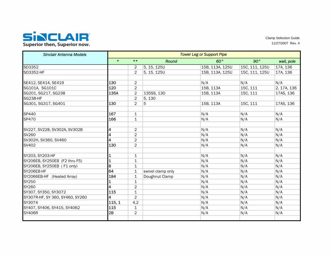
Clamp Selection Guide11/27/2007 Rev. 4
Sinclair Antenna Models* ** Round 60° 90° wall, pole
SD3352 2 5, 15, 125U 15B, 113A, 125U 15C, 111, 125U 17A, 136SD3352-HF 2 5, 15, 125U 15B, 113A, 125U 15C, 111, 125U 17A, 136
SE412, SE414, SE419 130 2 N/A N/A N/ASG101A, SG101C 120 2 15B, 113A 15C, 111 2, 17A, 136SG201, SG217, SG238 135A 2 135SS, 130 15B, 113A 15C, 111 17AS, 136SG238-HF 2 5, 130SG301, SG317, SG401 130 2 5 15B, 113A 15C, 111 17AS, 136
SP440 167 1 N/A N/A N/ASP470 166 1 N/A N/A N/A
SV227, SV228, SV302A, SV302B 4 2 N/A N/A N/ASV260 4 2 N/A N/A N/ASV302H, SV360, SV460 4 2 N/A N/A N/ASV402 130 2 N/A N/A N/A
SY203, SY203-HF 1 1 N/A N/A N/ASY206EB, SY250EB (F2 thru F5) 1 1 N/A N/A N/ASY206EB, SY250EB ( F1 only) 8 1 N/A N/A N/ASY206EB-HF 64 1 swivel clamp only N/A N/A N/ASY2066EB-HF (Heated Array) 184 1 Doughnut Clamp N/A N/A N/ASY250 1 1 N/A N/A N/ASY260 4 2 N/A N/A N/ASY307, SY350, SY3072 115 1 N/A N/A N/ASY307R-HF, SY 360, SY460, SY260 4 2 N/A N/A N/ASY3074 115, 1 4,2 N/A N/A N/ASY407, SY406, SY415, SY4062 115 1 N/A N/A N/ASY406R 2B 2 N/A N/A N/A
Tower Leg or Support Pipe

I

II

III

IV
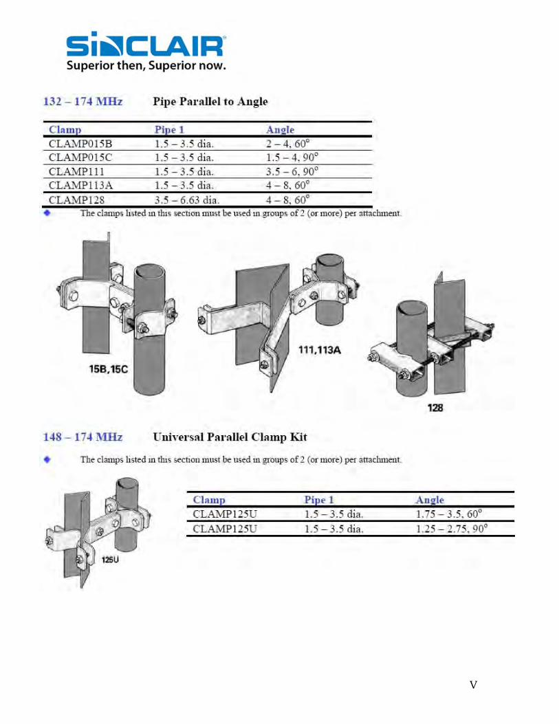
V

VI

VII
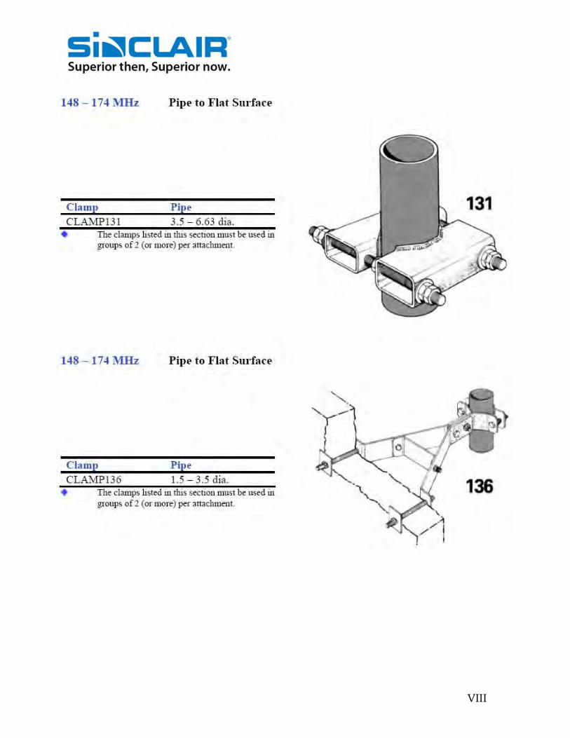
VIII
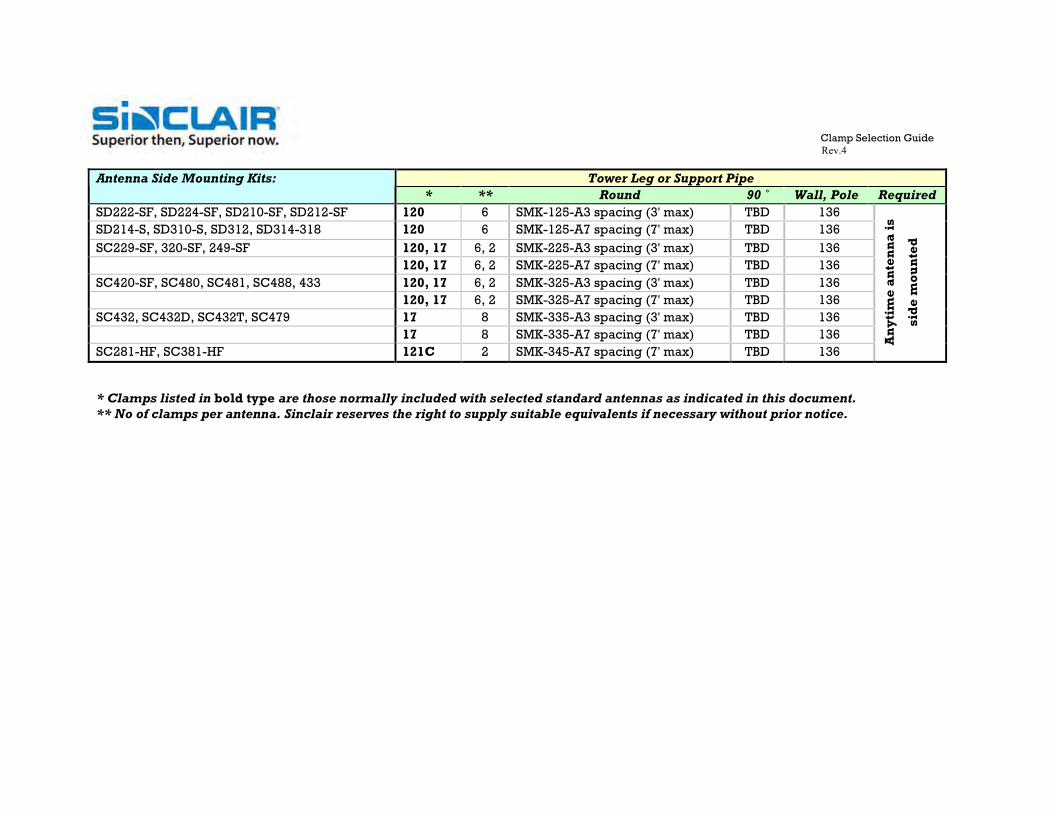
Clamp Selection Guide Rev.4
Tower Leg or Support Pipe Antenna Side Mounting Kits:
* ** Round 90 ˚ Wall, Pole Required SD222-SF, SD224-SF, SD210-SF, SD212-SF 120 6 SMK-125-A3 spacing (3' max) TBD 136 SD214-S, SD310-S, SD312, SD314-318 120 6 SMK-125-A7 spacing (7' max) TBD 136 SC229-SF, 320-SF, 249-SF 120, 17 6, 2 SMK-225-A3 spacing (3' max) TBD 136 120, 17 6, 2 SMK-225-A7 spacing (7' max) TBD 136 SC420-SF, SC480, SC481, SC488, 433 120, 17 6, 2 SMK-325-A3 spacing (3' max) TBD 136 120, 17 6, 2 SMK-325-A7 spacing (7' max) TBD 136 SC432, SC432D, SC432T, SC479 17 8 SMK-335-A3 spacing (3' max) TBD 136 17 8 SMK-335-A7 spacing (7' max) TBD 136 SC281-HF, SC381-HF 121C 2 SMK-345-A7 spacing (7' max) TBD 136
An
ytim
e an
ten
na
is
sid
e m
oun
ted
* Clamps listed in bold type are those normally included with selected standard antennas as indicated in this document. ** No of clamps per antenna. Sinclair reserves the right to supply suitable equivalents if necessary without prior notice.

IX

X
ITEM NO. DESCRIPTION QTY.1 UPPER SUPPORT ASSEMBLY (103”) 1 2 LOWER SUPPORT PIPE, 104” LG. 2 3 120 CLAMP ASSEMBLY 6 4 #17 CLAMP ASSEMBLY 2
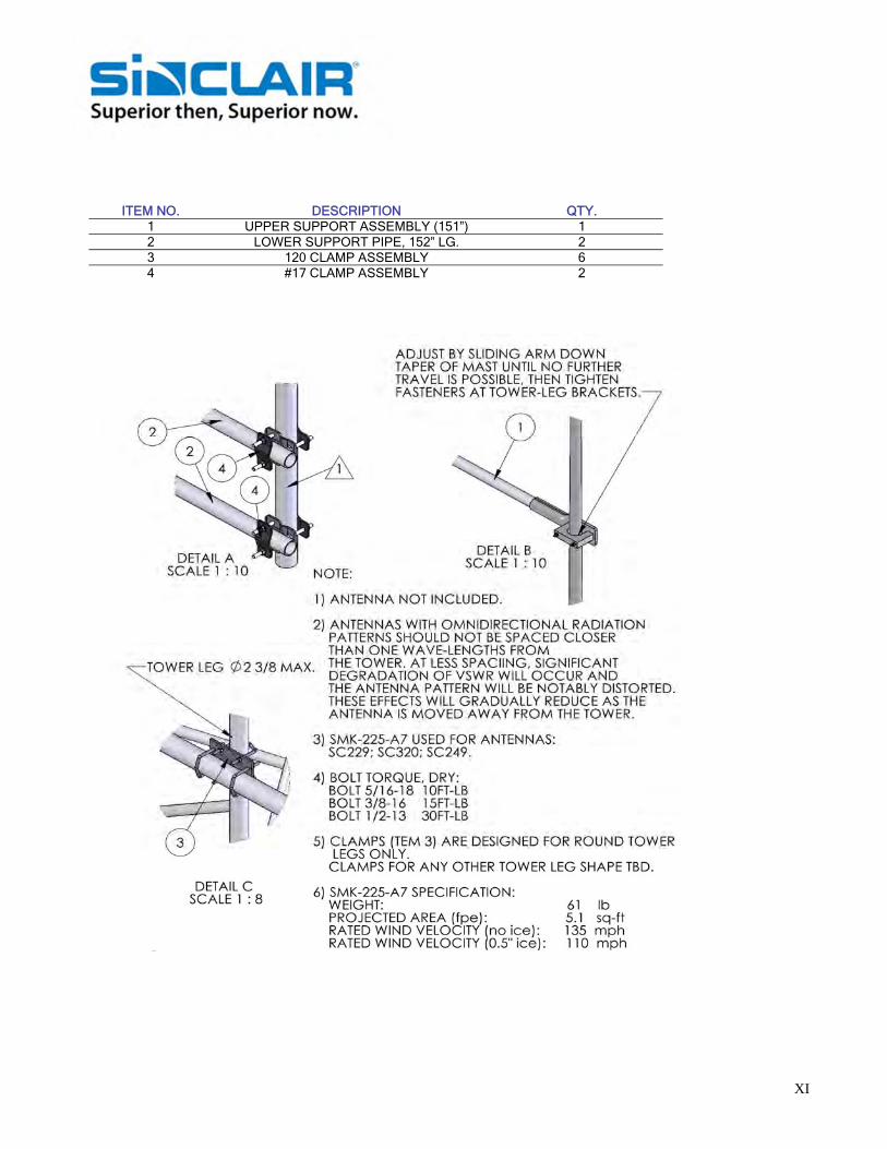
XI
ITEM NO. DESCRIPTION QTY.1 UPPER SUPPORT ASSEMBLY (151”) 1 2 LOWER SUPPORT PIPE, 152” LG. 2 3 120 CLAMP ASSEMBLY 6 4 #17 CLAMP ASSEMBLY 2

XII

XIII
ITEM NO. DESCRIPTION QTY.1 UPPER SUPPORT ASSEMBLY (103”) 1 2 #17 CLAMP ASSEMBLY 8 3 LOWER SUPPORT PIPE, 104” LG. 2

XIV

XV

XVI
ITEM NO. DESCRIPTION QTY.1 ALUM. PIPE, 68” LG. 2 2 120 CLAMP ASSEMBLY 6

XVII
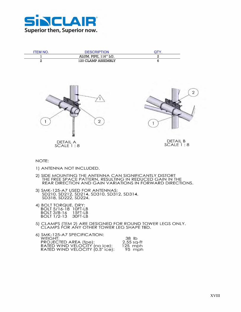
XVIII
ITEM NO. DESCRIPTION QTY.
1 ALUM. PIPE, 116” LG. 2 2 120 CLAMP ASSEMBLY 6

XIX

XX
ITEM NO. DESCRIPTION QTY.
1 #17 CLAMP ASSEMBLY 8 2 SUPPORT 1 3 ADAPTOR, U-CLAMP 1 4 UPPER SUPPORT PIPE 1 5 5/16-18 x 2.50" HX.HD. BOLT SS 2 6 5/16-18 x 6.50" HX.HD. BOLT SS 2 7 NUT # 5/16-18 , SS 4 8 LOCK WASHER 5/16, SS 4 9 PLAIN WASHER, 5/16, SS 4
10 LOWER SUPPORT 2

XXI

XXII
ITEM NO. DESCRIPTION QTY.
1 LOWER SUPPORT 2 2 UPPER SUPPORT 1 3 UPPER SUPPORT, CLAMP 1 4 121C, CLAMP 2 5 BOLT 3/8-16 x 3.5, GR 2, HDG 2 6 LOCK WASHER, 3/8 HDG 2 7 NUT# 3/8-126, OV-SIZE, HD 2

XXIII
MO-32 MO-ST MAB XCR
Mobile Parts and Hardware B-NUT Brass nut and ‘O’ ring for M series mounts B-NUT38 Brass nut and ‘O’ ring for W series mounts BHB Hinged trunk lid bracket, black BMAB Pkg. of 5, ball and set screw for BSFT-118, black BMMB-34 Mirror bracket, ¾” hole, black BMMB-38 Mirror bracket, ⅜” hole, black BMN Black mount nut for ¼” wave antenna BTGB-34 Trunk groove, ‘L’ bracket, ¾” hole, black BTGB-38 Trunk groove, ‘L’ bracket, ⅜” hole, black C-NUT Chrome mount nut for ¼” wave antenna HB Hinged trunk lid bracket, chrome MO-32 Pkg. of 12 10-32 x 3/16 set screw MO-32B Pkg. of 12 10-32 x 3/16 set screw, black MO-ST Pkg. of 12, 10 x 5/8 self tap screw MO-TL Pkg. of 12, 10-32 x 5/16 set screw M8-32 Pkg. of 12, 8-32 x 3/16 set screw MAB Pkg. of 5, ball and set screw for SFT-118 MANUT Brass nut and ‘O’ ring for MATM series mounts MMB-34 Mirror bracket, ¾”, hole, chrome MMB-38 Mirror bracket, ⅜”, hole, chrome MMGSK Pkg. 6, seal gaskets fit around ¾” mount nut MRC Chrome rain cap for 1 1/8” – 18 mounts MXGSK Pkg. of 6, seal gaskets fit around ⅜” snap-in-mounts NGP-GSK Pkg. of 3, 2- ¼” diameter seal gaskets for XNGP flange mount O RING Pkg. of 6, ‘0’ ring for ¾” or ⅜” mounts PL-34 Pkg. of 6, ¾” plastic hole plug PL-38 Pkg. of 6, 3/8” plastic hole plug TGB-34 Trunk groove, ‘L’ bracket, ¾” hole, stainless TGB-38 Trunk groove, ‘L’ bracket, ⅜” hole, stainless X-NUT Brass nut and ‘O’ ring for X series mounts XCR Contact replacement kit for X series snap-in mount Cable and Connectors RG-58 RG-58A/U cable, 95% shield RG-58A/U-500 500’ RG-58A/U cable, 95% shield, boxed RG-58A/U-1000 1000’ RG-58A/U cable, 95% shield, boxed RG-58U RG-58/U solid conductor cable, 95% shield RG-58U-500 500’ RG-58/U cable, 95% shield, boxed RG58U-1000 1000’ RG-58/U cable, 95% shield, boxed RG-213 RG-213 cable, 95% shield MBNC BNC crimp-on connector for RG-58U MCN-58 ‘N’connector for RG-58 type cable MCPL9 Pkg. of 5, crimp-on, PL259 for RG-58/U MTNC TNC crimp-on connector for RG-58/U
MRC C-NUT BMN
TGB-38 BTGB-34 BTGB-38
MBNC
MUHF MCPL9
MMB-38
MPL9
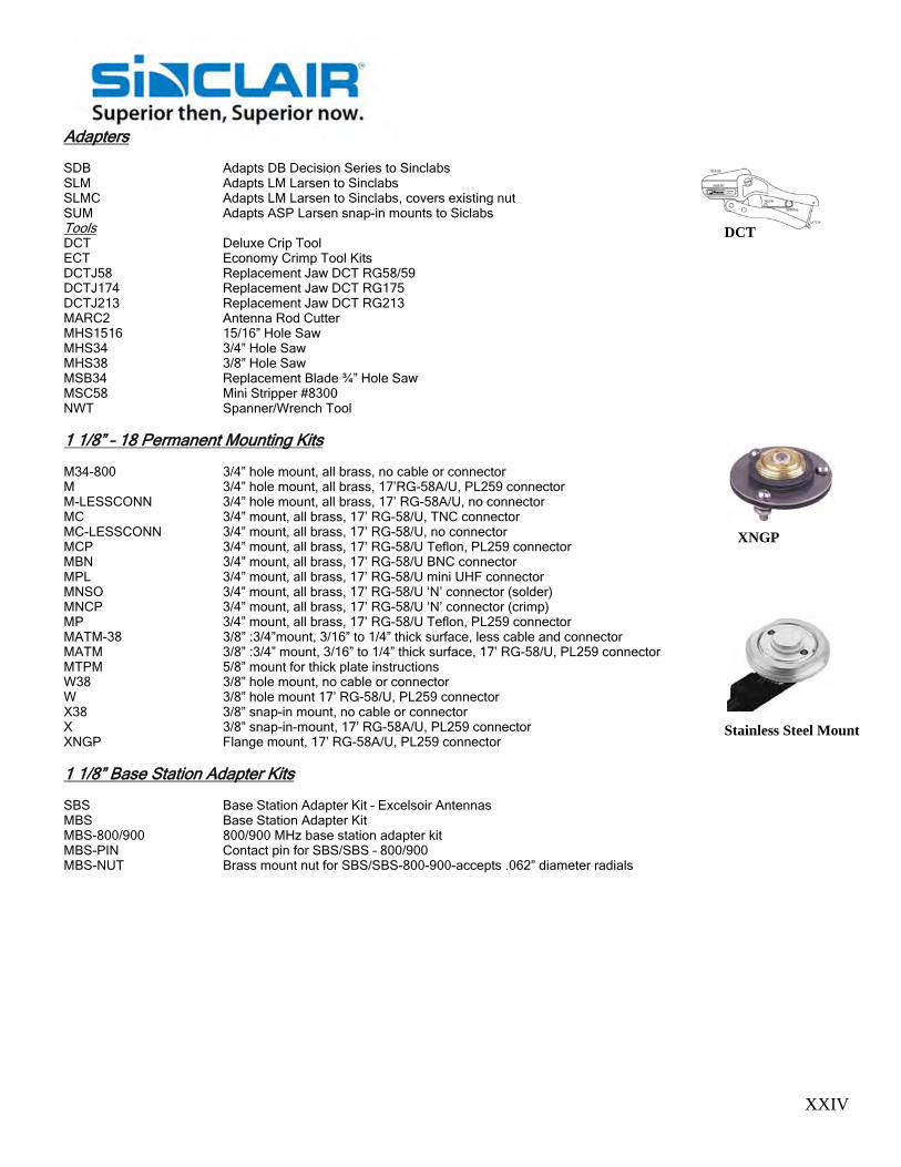
XXIV
Adapters SDB Adapts DB Decision Series to Sinclabs SLM Adapts LM Larsen to Sinclabs SLMC Adapts LM Larsen to Sinclabs, covers existing nut SUM Adapts ASP Larsen snap-in mounts to Siclabs Tools DCT Deluxe Crip Tool ECT Economy Crimp Tool Kits DCTJ58 Replacement Jaw DCT RG58/59 DCTJ174 Replacement Jaw DCT RG175 DCTJ213 Replacement Jaw DCT RG213 MARC2 Antenna Rod Cutter MHS1516 15/16” Hole Saw MHS34 3/4” Hole Saw MHS38 3/8” Hole Saw MSB34 Replacement Blade ¾” Hole Saw MSC58 Mini Stripper #8300 NWT Spanner/Wrench Tool 1 1/8” – 18 Permanent Mounting Kits M34-800 3/4” hole mount, all brass, no cable or connector M 3/4” hole mount, all brass, 17’RG-58A/U, PL259 connector M-LESSCONN 3/4” hole mount, all brass, 17’ RG-58A/U, no connector MC 3/4” mount, all brass, 17’ RG-58/U, TNC connector MC-LESSCONN 3/4” mount, all brass, 17’ RG-58/U, no connector MCP 3/4” mount, all brass, 17’ RG-58/U Teflon, PL259 connector MBN 3/4” mount, all brass, 17’ RG-58/U BNC connector MPL 3/4” mount, all brass, 17’ RG-58/U mini UHF connector MNSO 3/4” mount, all brass, 17’ RG-58/U ‘N’ connector (solder) MNCP 3/4” mount, all brass, 17’ RG-58/U ‘N’ connector (crimp) MP 3/4” mount, all brass, 17’ RG-58/U Teflon, PL259 connector MATM-38 3/8” :3/4”mount, 3/16” to 1/4” thick surface, less cable and connector MATM 3/8” :3/4” mount, 3/16” to 1/4” thick surface, 17’ RG-58/U, PL259 connector MTPM 5/8” mount for thick plate instructions W38 3/8” hole mount, no cable or connector W 3/8” hole mount 17’ RG-58/U, PL259 connector X38 3/8” snap-in mount, no cable or connector X 3/8” snap-in-mount, 17’ RG-58A/U, PL259 connector XNGP Flange mount, 17’ RG-58A/U, PL259 connector 1 1/8” Base Station Adapter Kits SBS Base Station Adapter Kit – Excelsoir Antennas MBS Base Station Adapter Kit MBS-800/900 800/900 MHz base station adapter kit MBS-PIN Contact pin for SBS/SBS – 800/900 MBS-NUT Brass mount nut for SBS/SBS-800-900-accepts .062” diameter radials
XNGP
Stainless Steel Mount
DCT

XXV
1 1/8” -18 Temporary Mounting Kits 3/ 1/4” Diameter Magnetic Mounts G Complete with 12’ RG-58A/U PL259 connector GC Complete with 12’ RG-58/U, TNC connector GBN Complete with 12’ RG-58/U, BNC connector GPL Complete with 12’ RG-58/U, mini UHF connector RBG Complete with 12” RG-58A/U, PL259 connector, rubber boot, black RBGBN Complete with 12” RG-58/U, BNC connector, rubber boot, black RBGPL Complete with 12’ RG-58/U, mini UHF connector, rubber boot, black RBGP Complete with 12” RG-58/U, Teflon PL259 connector, rubber boot, black RBGN Complete with 12’ RG-58/U, “N connector, rubber boot, black RG Complete with 12’ RG-58A/U, PL259 connector, rubber boot RGC Complete with 12’ RG-58/U, TNC connector, rubber boot RGBN Complete with 12’ RG-58/U, BNC connector, rubber boot RGPL Complete with 12’ RG-58/U, mini UHF connector, rubber boot RGP Complete with 12’ RG-58/U, Teflon PL259 connector, rubber boot RGN Complete with 12’ RG-58/U, ‘N’ connector, rubber boot G-EX Low Profile, c/w 12’ RG-58A/U, PL259 connector GC-EX Low Profile, c/w 12’ RG-58/U, TNC connector GBN-EX Low Profile, c/w 12’ RG-58/U, BNC connector GPL-EX Low Profile, c/w 12’ RG-58/U, mini UHF connector GP-EX Low Profile, c/w 12’ RG, Teflon PL259 connector GN-EX Low Profile, c/w 12’ RG-58/U ‘N’ connector BG-EX Low Profile, c/w 12’ RG-58A/U, PL259 connector, black BGC-EX Low Profile, c/w 12’ RG-58/U, TNC connector, black BGBN-EX Low Profile, c/w 12’ RG-58/U, BNC connector, black BGPL-EX Low Profile, c/w 12’ RG-58/U, mini connector, black BGP-EX Low Profile, c/w 12’ RG-58/U, Teflon PL259 connector BGN-EX Low Profile, c/w 12’ RG-58/U, ‘N’ connector, black 2 3/8” Diameter Magnetic Mounts BGM Complete with 12’ RG-58A/U, PL259 connector, black BGMC Complete with 12’ RG-58/U, TNC connector, black BGMBN Complete with 12’ RG-58/U, BNC connector, black BGMPL Complete with 12’ RG-58/U, mini UHF connector, black BGMP Complete with 12’ RG-58/U, Teflon PL259 connector, black BGMN Complete with 12’ RG-58/U, ‘N’ connector, black GM Complete with 12’ RG-58A/U, PL259 connector GMC Complete with 12’ RG-58/U, TNC connector GMBN Complete with 12’ RG-58/U, BNC Connector GMPL Complete with 12’ RG-58/U, mini UHF connector GMP Complete with 12’ RG-58/U, Teflon PL259 connector GMN Complete with 12’ RG-58, ‘N’ connector Trunk Lid Mounts TTT Mount only, no cable or connector T 17’ RG58A/U, PL259 TC 17’ RG58/U, TNC connector TBN 17’ RG58/U, BNC connector TPL 17’ RG58/U, mini UHF connector TN 17’ RG58/U ‘N’ connector TP 17’ RG58/U, Teflon PL259 connector
G Series
RGB Mount
GM Series
RG Series
T Series

XXVI
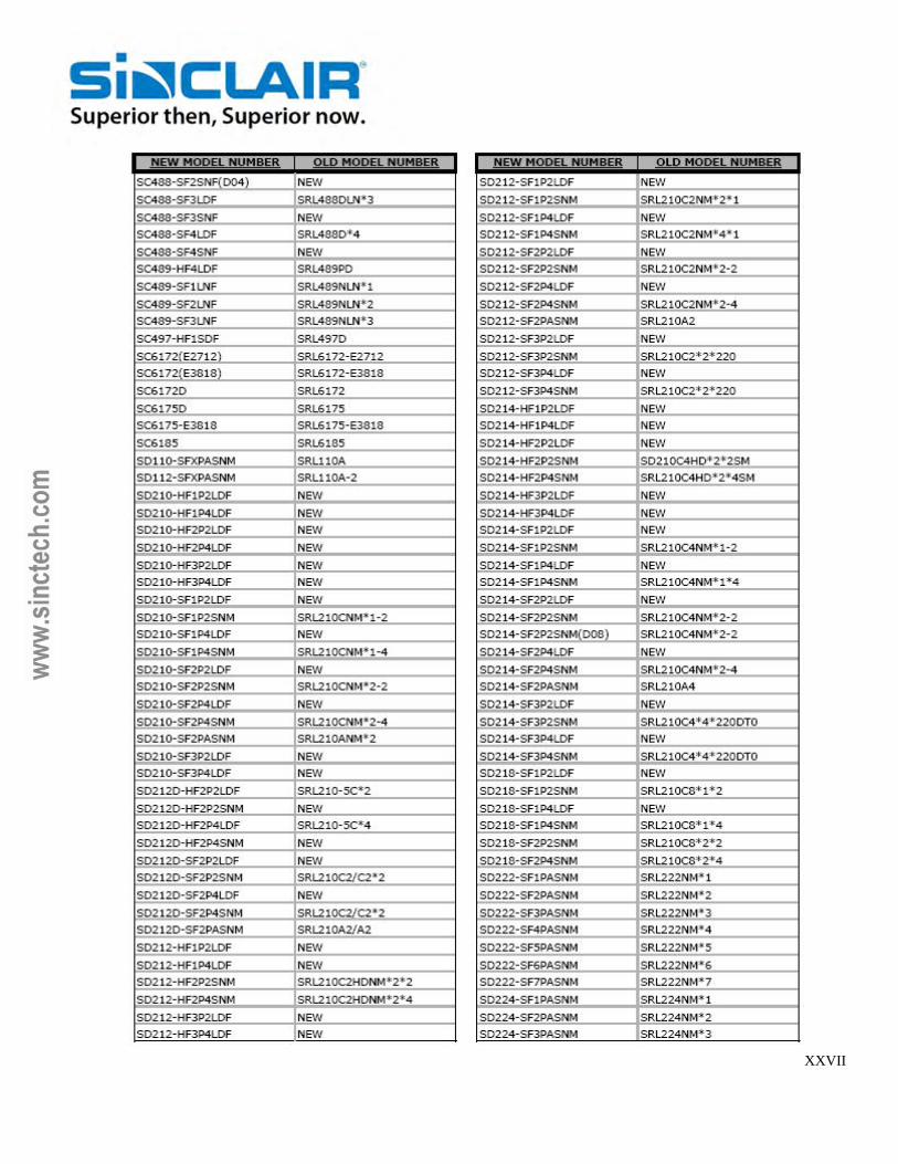
XXVII
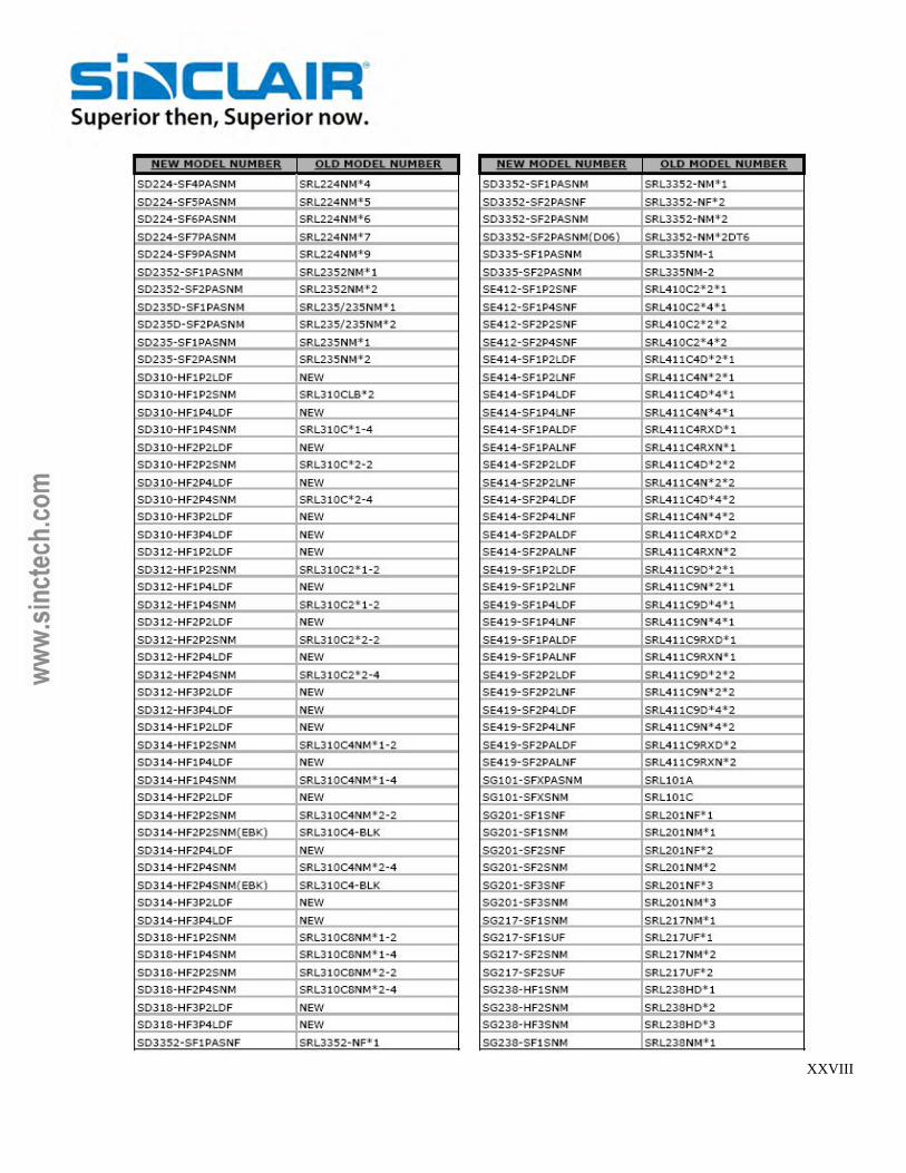
XXVIII

XXIX

XXX

XXXI

XXXII

SINCLAIR TECHNOLOGIES INC. – TERMS AND CONDITIONS OF SALE
“INCOTERMS” shall mean the international rules for the interpretation of
trade terms of the International Chamber of Commerce as in force at the
date when the contract for the sale and purchase of the Products is made.
“The Products” shall mean any products or services supplied by the
Supplier.
“The Purchaser” shall mean the person, firm or company purchasing the
products or services supplied by the Supplier.
“The Supplier” shall mean Sinclair Technologies Inc.
1. Basis of Sale
1.1 The Supplier shall sell and the Purchaser shall purchase the
Products in accordance with an accepted written quotation from
the Supplier or an accepted written purchase order from the
Purchaser. In each case the relevant sale and purchase contract
shall be subject to these terms and conditions, which shall
govern the contract to the exclusion of any other terms and
conditions subject to which any such quotation is accepted or
purported to be accepted, or any such order is made or
purported to be made by the Purchaser.
1.2 No variation to these terms and conditions shall be binding
unless agreed in writing between the authorized representatives
of the parties.
1.3 The Supplier’s employees or agents are not entitled to give or
make any undertakings, representations or warranties
concerning the Products other than as set out in current
standard specifications of the Supplier or as specifically
authorized by an officer of the Supplier in writing.
2. Orders and Specifications
2.1 All purchase orders should be directed to the Supplier at its
above address giving all information necessary to process the
Purchaser’s order and the Purchaser will be responsible to the
Supplier for ensuring the accuracy of the terms of any order
submitted by the Purchaser.
2.2 No order submitted by the Purchaser shall be deemed to be
accepted by the Supplier unless and until confirmed in writing by
the Supplier’s authorized representative by way of
acknowledgement of order.
2.3 If the Products are to be manufactured or any process is to be
applied to the Products by the Supplier in accordance with a
specification submitted by the Purchaser, the Purchaser shall
indemnify the Supplier against all loss, damages, costs and
expenses awarded against or incurred by the Supplier in
connection with or paid or agreed to be paid by the Supplier in
settlement of any claim for infringement of any patent, copyright,
design, trade mark or other industrial or intellectual property
rights of any other person which results from the Supplier’s use
of the Purchaser’s specification.
2.4 The Supplier reserves the right to make any changes in the
specification of the Products which are required to conform with
any applicable safety or other statutory requirements or which
do not materially affect their quality or performance.
2.5
2.5.1 No order which has been accepted by the Supplier may
be cancelled by the Purchaser except with the Supplier’s written
agreement and on terms that the Purchaser shall indemnify the
Supplier in full against all loss (including loss of profit), costs
(including costs of all labour and materials used), damages,
charges and expenses incurred by the Supplier as a result of
cancellation and sales applicable. In the case of specially
engineered or customized Products the full amount will be
charged.
2.5.2 Changes to acknowledged orders will only be accepted
upon terms that protect the Supplier against loss.
3. Price
3.1 The price of the Products shall be the Supplier’s quoted price or,
where no price has been quoted (or a quoted price is no longer
valid), the price listed in the Supplier’s published price list
current at the date of acceptance of the order less any agreed
discount currently applicable to the Purchaser. All prices quoted
are valid unless otherwise specified in the quotation for 30 days
only or until earlier acceptance by the Purchaser, after which
they may be altered by the Supplier without giving notice to the
Purchaser.
4. Payment Terms
4.1 All orders are subject to credit approval before acceptance.
Time of payment shall be of the essence of the contract. Interest
of 2% per month will be charged on all overdue accounts (both
before and after judgement).
Prices do not include sales or value added taxes for which the
Purchaser will be responsible.
Unless otherwise agreed, payment will be cash in advance prior
to shipment. Shipments will be made on open account only after
approval by our Credit Department. Where open account is
approved, Terms are net 30 days from date of invoice.
4.2 Terms may be subject to change without notice to the Purchaser
to reflect any increase in the cost to the Supplier due to any
factor beyond the Supplier’s control (such as without limitation
any foreign exchange fluctuation, currency regulation, alteration
of duties or significant increase in the costs of labour, materials
or other costs of manufacture).
5. Shipment/Carriage
5.1 All shipments are FOB Supplier’s premises. Carriage, insurance
and freight charges are collect and for the Purchaser’s account
unless otherwise specified. If carrier is unspecified, Supplier is
not responsible for selecting the cheapest or fastest routing.
Claims for shortages, other than loss in transit, must be made
within thirty (30) days of shipment from Supplier’s premises.
6. Claims for Damage or Loss in Transit
6.1 Claims for damage or loss incurred in transit must be made
immediately by the Purchaser against the carrier. Though the
Supplier has no liability, if requested, the Supplier will assist in
the Purchaser’s claim against the carrier provided the Purchaser
indemnifies the Supplier against any loss or expense incurred by
the Supplier in so doing.
7. Delays
7.1 Dates for delivery of the Products are approximate only and the
Supplier shall not be liable for any delay howsoever caused.
Time shall not be of the essence in respect of delivery.
7.2 The Supplier shall not be liable for inability to fulfil contractual
obligations when the causes thereof are due to act of God,
explosion, storm or lightning damage, flood, tempest, fire or
accident, war, riot, sabotage, terrorist acts, acts of government,
import or export regulations or embargoes, strikes, lock outs or
other industrial actions or trade disputes, difficulties in obtaining
raw materials, labour, fuel, parts or machinery, power failure or
breakdown in machinery or any other act or matter beyond the
Supplier’s reasonable control.
7.3 Where Products are to be delivered in instalments, each delivery
shall constitute a separate contract and failure by the Supplier to
deliver any one or more of the instalments in accordance with
these terms and conditions or any claim by the Purchaser in
respect of any one or more instalment shall not entitle the
Purchaser to treat the contract as a whole as repudiated.
7.4 If the Supplier fails to deliver the Products for any reason other
than any cause beyond the Supplier’s reasonable control or
default by the Purchaser, any liability of the Supplier shall be
limited to the excess (if any) of the cost to the Purchaser (in the
cheapest available market) of similar products to replace those
not delivered over the price of the Supplier’s Products.
8. Title
8.1 Notwithstanding delivery and the passing of risk in the Products,
or any other provisions of these terms and conditions, title and
property in the Products shall not pass to the Purchaser until the
Supplier has received in cash or cleared funds payment in full of
the price of the Products and all other products agreed to be
sold by the Supplier to the Purchaser for which payment is then
due.
8.2 Until property and title has passed the Purchaser shall keep the
Products properly insured to their full value.
8.3 Until such time as title and property in the Products passes to
the Purchaser (and provided the Products are still in existence
and have not been resold), the Supplier shall be entitled at any
time to require the Purchaser to deliver up the Products to the
Supplier and, if the Purchaser fails to do so forthwith, to enter on
the Purchaser’s premises or those of any third party where the
Products are stored and take all appropriate steps to repossess
them.
8.4 The Purchaser shall not be entitled to pledge or in any way
charge by way of security for any indebtedness any of the
Products which remain the Supplier’s property.
9. Repairs
9.1 Authorization must be obtained before returning any material for
repair. Items not covered under warranty provisions will be
subject to a minimum service charge.
10. Limited Warranty
10.1 Supplier’s antenna Products are warranted against defects in
materials and workmanship under normal use and service for a
period of five years from date of shipment for all mechanical and
electrical performance rating with the exception of low passive
intermodulation (“PIM”) rated antennas for which the PIM rating
is warranted for two years from date of shipment. Antenna PIM
ratings may be affected over time by exposure to harsh
environmental conditions. Supplier’s filter Products and systems
are warranted against defects in material and workmanship
under normal use and service for a period of two years from
date of shipment. This limited warranty does not extend to any
Products that have been subject to misuse, neglect, accident,
improper installation or application, nor shall it extend to
Products which have been repaired or altered outside Supplier’s
factory. In the event of a defect covered by this limited warranty,
Supplier’s sole obligation and Purchaser’s sole remedy shall be
that Supplier, upon receipt of the defective Product, shall either
repair or replace, at its option, the defective Product and return it
to the Purchaser. Supplier shall not be liable under any
circumstances for any special, indirect consequential, incidental,
punitive or exemplary damages arising out of or in any way
connected with its lost profits, loss of use, lost data or for any
damages or sums paid by Purchaser to third parties, even if
Supplier has been advised of the possibility of such damages.
The foregoing limitation of liability shall apply whether any claim
is based upon principles of contract, warranty, negligence or
other tort, breach of any statutory duty, principles of indemnity or
contribution, the failure of any limited or exclusive remedy to
achieve its essential purpose, or otherwise. Supplier is not
liable for replacement of any product damaged by lightning, wind
or any other act of God or other event beyond the Supplier’s
reasonable control. No Product may be accepted for
replacement or repair without written prior authorization from
Supplier. All shipping charges on returned Product are the
Purchaser’s responsibility and must be prepaid. Product
replacement or repair is subject to an examination by Supplier
concluding that the Product was defective at the time of
manufacture. Except for the limited warranty set out above,
10.2 For the avoidance of doubt the Supplier shall be under no
Supplier does not make, and hereby expressly disclaims, any and
all other express and implied warranties, including, but not limited
to warranties of merchantability, fitness for a particular purpose
and any and all warranties arising from trade practice, custom or
any other legal theory.
11. Insolvency of Purchaser
11.1 This clause applies if:-
11.1.1 The Purchaser makes any voluntary arrangement with its
creditors or becomes subject to an administration order or
(being an individual or firm) becomes bankrupt or (being a
company) goes into liquidation (otherwise than for the
purposes of amalgamation or reconstruction); or
11.1.2 An encumbrancer takes possession, or a receiver or
administrative receiver is appointed, of any of the property
or assets of the Purchaser; or
11.1.3 The Purchaser ceases, or threatens to cease to carry on
business; or
11.1.4 The Supplier reasonably apprehends that any of the
events mentioned above is about to occur in relation to
the Purchaser and notifies the Purchaser accordingly.
11.2 If this clause applies then, without prejudice to any right or remedy
available to the Supplier, the Supplier shall be entitled to cancel
the contract or suspend any further deliveries under the contract
without any liability to the Purchaser, and if the Products have
been delivered but not paid for the price shall become immediately
due and payable notwithstanding any previous agreement or
arrangement to the contrary.
12. Third Party Intellectual Property Rights - Indemnity
12.1 The Supplier shall indemnify the Purchaser against any claims for
infringement of any third party intellectual property rights arising
from the Products or the use of any of the Products; provided,
however, that the Supplier shall in no event be liable for damages
or loss of a consequential nature, including loss of profit. This
indemnity shall not apply to any infringement based on
compliance with specifications or instructions of the Purchaser or
on any use of the Products not stipulated in the contract or on any
use of the Products in association or combination with equipment
not supplied by the Supplier. This indemnity is further conditional
upon the Purchaser giving to the Supplier the earliest possible
written notice of any claim being made or action threatened or
brought against the Purchaser, conditional upon the Purchaser not
having made any admission which might be prejudicial to such
claim or action and upon the Purchaser permitting the Supplier at
the Supplier’s own expense to conduct any ensuing litigation and
all negotiations for a settlement of the claim. The Supplier shall be
entitled to modify or replace any infringing items so that they
become non-infringing. The Purchaser shall be obliged to take
such steps as the Supplier may reasonably request, and to use its
best endeavours, to mitigate the effect of any claim.
13. General
13.1 If any provision of these terms and conditions is held by any
competent authority to be invalid or unenforceable in whole or in
part the validity of the other provisions of these terms and
conditions and the remainder of the provision in question shall not
be affected thereby.
13.2 Please supply Supplier correct shipping information including
address and postal code with your order and indicate your
preference for transportation and insurance.
13.3 When ordering, give operating frequencies to the nearest kHz
(Example: 456.272MHz). Components are tuned and tested at
exact specified operating frequencies, as required. Your order
cannot be properly processed without this information.
13.4 The contract shall be governed by the laws of Ontario, Canada
and each party hereby submits to the non-exclusive jurisdiction of
the Ontario courts.
Oct.’07
10