sims /t: - scholarspace.manoa.hawaii.edu · the water level originally anticipated was about +3...
TRANSCRIPT
"---
~===-•~======~,~======~ -----1
-----~
' !
I Y-0 ~iMI;"~D f '-----; · p;i:TNB=-S~if /
' 0
~OC,t>.TION ,
---------1 I TAK;MASA !' , 1 NTcF-NP-TiONP-L-, / \Nv.
!/------·· -.._.._j OJ I .
' SIMS I ·" .J I {!- I"< • ' / ·----:--·---( o:- fi-AWAII /1 I!! /t: _____ / - ~ I . ,2 ( ·----:r _\/) ' ' () -~
·. 0 ll -- . [) /o )-.. - '0 _;;r f! /:;:
/ ' I-.·-"! .;;: i"' f- ·- "'- u! ' ( ----o_ ,
.' '([_ ~-------/
L... ...J ~ I ) ~-1----~ ~-~-- '
"""' ~W....:s.s:
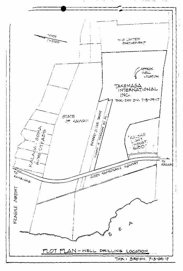
i'LOT flAN- ~'JeLL. D~ILLiNG. LOC.t:>TIO~
..... ~
......... State of Hawau DEI'><RTMENT OF LAND • NATURAL RESO\IliCES DIVISION OF WATER AND LAND DEVELOPMENT /.
DRILLER'S R JRT / ~------------~--
STAT! OOWALO Form 71(1)
Date of re~;,r.i,/,d..i~f£(. W~~~son ~~:gcr~~:ION t;>e;~NI:> ..... 0.' ~H.Ii.CA. ... A. OWNER ~.!J>P\.ii,I'IHii"'••'Y.~AME \<.Accl(D \U.\<ATII>tt) Wt.\,.1,;*\ ISLAND .H/I.~U B. GENERAL LOCATION . l4AkOKC. .... .... ....... . ..... . C. DRILLING COMPANY R.iC..'-\l>ll,.t)!,Qit) "t>R.I '-.\-\1-)C,. .. Go , D. TYPE OF RIG 3t. L. DRILLING COMPLETED .. 1/S~
:ro~'ES DRILLER~t>,.,£.:E
_ mbnth year
E. ELEVATION, msl: Top of drilling platform !> €.:a 1_ . _ ft. Bench mark a~_mJf.hod used to deter"ll£1! Height of drilling platform above ground surface -~- ft. elevation: ~----.5:"'-~lo. ... 8£o ...... f~'-?-~---
F. HOLE SIZE: 2.D ________________ inch dia. to S'8.Co .. ft. below drilling platform. "Sull..VIl~i llf.O inch dia. to ft. below drilling platform.
........ _____ inch dia. to ft. below drilling pl'!!form. G. CASING INSTALLED: f_ ~---- in. I.D. x ~4\--. in. wall solid section to . ...S..£..1----- ft. below drilling platform.
\ 2.,. ___ in. I.D. x Y""'\ in. wall perforated section to .. SB.Z.. ... ft. below drilling platform. Type of perforation L..o_ \.;:n/.'lii: fL.
H. ANNULUS: Grouted ___ 0 ....... ft. to .. L? .. _..-ft. below drilling platform. Gravel packed .. k. ft. to !)J .. __ O ft. below drilling platform.
I. PERMANENT PUMP INSTALLATION, Pump type, make, serial no. Capacity g.p.m. Motor type, H.P., .voltage, r.p.m. Depth of pump intake setting ft. below ... which elevation is ft. Depth of bottom of airline ft. below which elevation is ft.
HYDROLOGY I I / J. INITIAL WATER LEVEL S'~'S'tt. below drilling platform. Date of measurement. 1J{ ·~ 7 K. INITIAL CHLORIDE, '14.0 .. ppm, total depth of well 5"'7 0 ft. below drilnng platform7/J '85.. ... .... .
mpllng Date/
L. ~~~PING~'rJ,]s ~ 7
.. .. Reference point/,~;~> "f'Jt,/r/r(,.. wh~h elevation is-5'!.7.2 .. ~ ft.
Start water f~~el ---~ lA.-1-... +------ ..... ft below R. P. Start wale~ level -~"1._?_.,..__.. ft. below R. P. End water level .. S .. t.r"'t_,_ ~ ........ ft. below R. P. End water level __ ~-'-~-~--~ .. ·.·. ___ ft. below R. P. Depth of well sB_b . ft. below R. P. Depth of well __ ..,) ___ 8-_G:,___ _ __ ft. below R. P.
Elapsed Rate Draw· Cl- Temp. Elapsed Rate Draw· Cl- Temp.
(J __ Timet~o_u,) !Jr!. _,=;~ ~4/ F Q Timei~our~-- ~- ~~}r~ ~~-)t· F
• •' ··q···..,····r • C to Z:: 43<f .. to 2.. to 3 S";t~ " 'f ~J ... to 3 .... to +.5 1.~ /,... " "14[ to.
• • SUBSURFACE FORMATION
M. DRILLER'S LQG,
Depth, ft. .CL. to ~0 ...
.1.1 ... to 7£ . JC. .... to <tO ... 9l ...... toiJ'B .IJ9. ... to q~ 'x~ to~~ l':t«! ... toi!J. .~ .. l'i.b .... to .. ZlEL .. to ..... 2.-'IC.. .. to .2..50.. 2SLto ZJL
N. REMARKS,
Water Level Rock Description & Remarks ft.
.. ~!'.C.~ .. ~· .. ~~t . I:L~ ........ ~:~.!U<'l ~0~~~';' ............................... (>UY 8(D~eru:.wr
g~g~~ =~~laf'l9
.. -.i~~~f2AY . ,..,1$11 ~ ... tAt ..
Water Level Depth. ft. Rock Description & Remarks ft.
2+'- to 2,'10. Cl I'UliL!'S .R~ .. Z'l.L t~. k0 E~ (1I)(J(.. '-.!?At
31..' . to .70. /.· 'tl/>iS) ~ 'Jtb 3'11 t ~··· '13tM.Of£L .......... ~··
39L .... to4L::>.. ..IUJ:<.!iOJ .~ ... ~ 4i.itl ... to .1,~ C>.uPr~ ~M
4.3L ... to4S0 , ~~.····.· ... ·.·.·····.········~ ~lo .. to'!'li ~ . .. ... ... 'f 55'·'·· :~m P~C ~ rr ~·· .. tb"~fl2 . R .· l.lb&l( ···· ~¥ 281 "fo 56lz o~o·~§ ··· £if<}·
FOR OFFICIAL USE . FOR DRILLER'S USE
Job Name 'KII~C:K~:/
INSTRUCTIONS: Send three(3) copies to, Mana_g_er-Chief Engineer, _Division of Water and Land Development, P. 0. Box 373, Honolulu, Hawatt 96809. REFERENCES: Chapter 178) entitled "Artesian Wells, Generally," HRS, as amended by Act 123 SLH 19 0. Honolulu Board of Water Supply, "Rules and Regulations Provldmg for the Protection, Development and Conservation of Water Resources." Sec't 8·105(j) ... Powers, Outtes and Functions of the Board," Charter of the City and County of Honolulu, 1959.
Latitude \'i ' 4 l 4'1 Longitude l 6. f..; ~ OU c.4 Well No. 41 '.,[) ·OI Job No. LQOJ .....

' . I
~SrlAND RESOURCES, L TO .csdurce Management With lmaginatic
Water • Land • Energy
STEPHEN P BOWLES TEl..EPHONE Prt!sident 885-4759
KALOKO IRRIGATION WELL #1 4\ 1..0- ~~ '.
FINAL REPORT
SEPTEMBER 1985
P.O. Box 1656 • Kamuela, Hawaii 96743
! I '
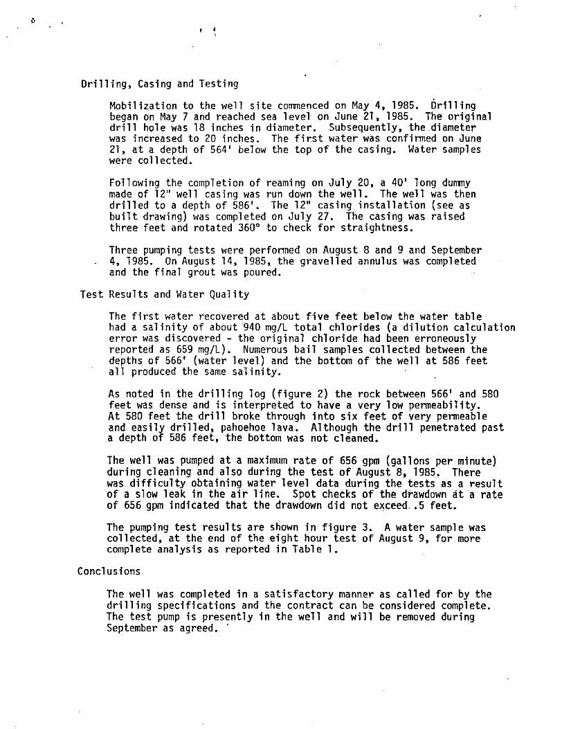
Drilling, Casing and Testing
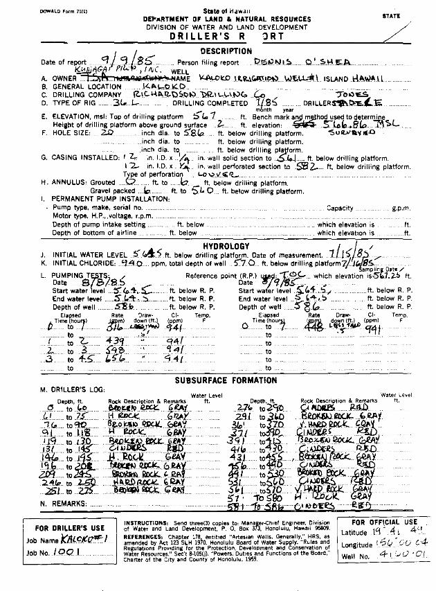
Mobilization to the well site commenced on May 4, 1985. Drilling began on May 7 and reached sea level on June 21, 1985. The original drill hole was 18 inches in diameter. Subsequently, the diameter was increased to 20 inches. The first water was confirmed on June 21, at a depth of 564' below the top of the casing. Water samples were collected.
Following the completion of reaming on July 20, a 40' long dummy made of 12" well casing was run down the well. The well was then drilled to a depth of 586'. The 12" casing installation (see as built drawing) was completed on July 27. The casing was raised three feet and rotated 360° to check for straightness.
Three pumping tests were performed on August 8 and 9 and September 4, 1985. On August 14, 1985, the gravelled annulus was completed and the final grout was poured.
Test Results and Water Quality
The first water recovered at about five feet below the water table had a salinity of about 940 mg/L total chlorides (a dilution calculation error was discovered - the original chloride had been erroneously reported as 659 mg/L). Numerous bail samples collected between the depths of 566' (water level) and the bottom of the well at 586 feet all produced the same salinity.
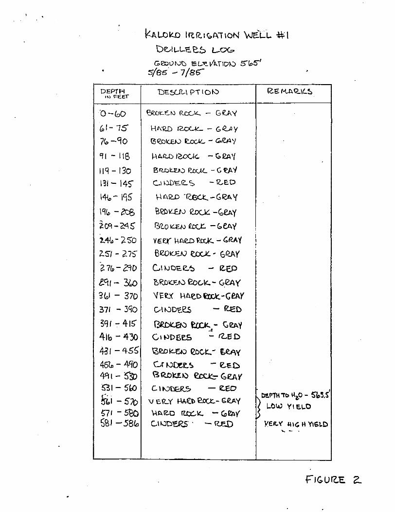
As noted in the drilling log (figure 2) the rock between 566' and 580 feet was dense and is interpreted to have a very low permeability. At 580 feet the drill broke through into six feet of very permeable and easily drilled, pahoehoe lava. Although the drill penetrated past a depth of 586 feet, the bottom was not cleaned.
The well was pumped at a maximum rate of 656 gpm (gallons per minute) during cleaning and also during the test of August 8, 1985. There was difficulty obtaining water level data during the tests as a result of a slow leak in the air line. Spot checks of the drawdown at a rate of 656 gpm indicated that the drawdown did not exceed .• 5 feet.
The pumping test results are shown in figure 3. A water sample was collected, at the end of the eight hour test of August 9, for more complete analysis as reported in Table 1.
Conclusions
The well was completed in a satisfactory manner as called for by the drilling specifications and the contract can be considered complete. The test pump is presently in the well and will be removed during September as agreed. ·
•
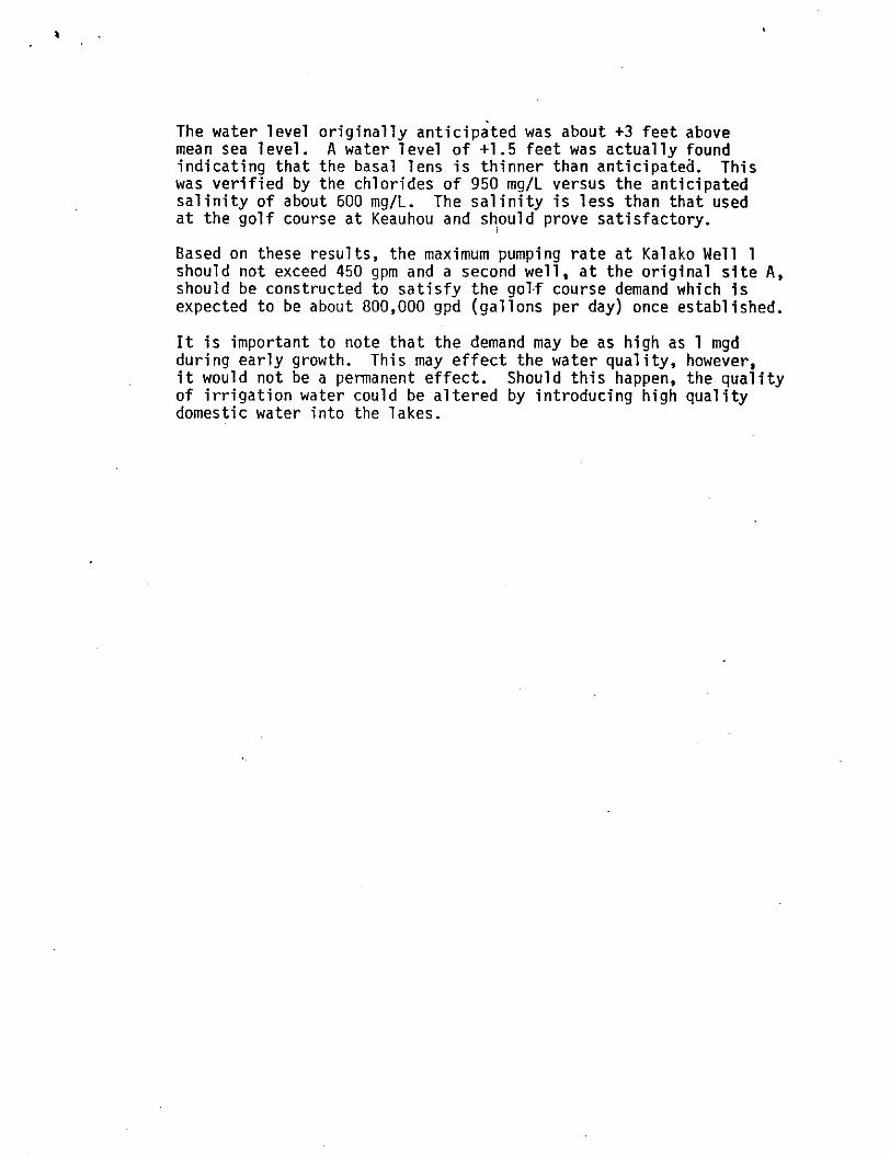
The water level originally anticipated was about +3 feet above mean sea level. A water level of +1.5 feet was actually found indicating that the basal lens is thinner than anticipateo. This was verified by the chlorides of 950 mg/L versus the anticipated salinity of about 600 mg/L. The salinity is less than that used at the golf course at Keauhou and should prove satisfactory.
' Based on these results, the maximum pumping rate at Kalako Well 1 should not exceed 450 gpm and a second well, at the original site A, should be constructed to satisfy the golf course demand which is expected to be about 800,000 gpd (gallons per day) once established.
It is important to note that the demand may be as high as 1 mgd during early growth. This may effect the water quality, however, it would not be a permanent effect. Should this happen, the quality of irrigation water could be altered by introducing high quality domestic water into the lakes.

S:io t: .
S""B~
T ~ r'
KALDK.O "IQ.R..\G.~--~~0"' WELL 1.
~
... ~.,
"' !. ..
'• ... A
...... A
b
... b.
A .. • ... .. .... • ... ...
.... .. !> ... .....
A f: . •
AS a\)IL.I q/1/85"
... l. .. A
""' t...t..
.... 1'>.
" "'
II. A
Al
!>A
.. , A
A
A .. ....
~~.~ A
A
A
I Z "LD. 'OLAt-:l~ C.A.~I IVG f.\. ~"1-'Z COIZ.I"E::N A'ST M
~· vJp.,u,_ 11-\IC.It..Nt:.SS
5.1\NO
~-::!:>.: 101>.1:. IC. ET@ S'loO I
· \,lt'ITf".~ L'l:.v'E.L @.E.L.~v'~IOP-+ 1.6' '51-lvTI£f:.. ~~~
L,...F:.-+--=- 1:\ ~4 2. CCIO'E.IV A ~IM
I
•
DEPT I-'! 1t-:~ ~EEl
n-eoo G,l-75
7<o -90
'II - liS
llq -130
1~1- 145" 14{.,- 195
19~-~
i C'l - '2."\ s 1."1-lD - ;2. so 2-SJ- 2.7~
n~o- cw ectt- ?:ko %,1- 370
371 - 3'iO
3'H- 41~ 41to- 430
~t-455
467,- 4-Cj'O
4-<11- 5~ 91-5~ , .... 57,1-57()
':;71 - 5Bo SSt -58/a
kA.LOk.O I!C.RI(:.P.IICN 'v-Ji'LL ~I D~IL-\...i:, ~t:> L-oG
Geol)tvt) SL:t:. V~IID10 5"!o5"' '5(8!5 - 7 /8b >
DE~\ PIIDIV R.e: M.AIC..IL~
e:Ro~::-!C. IV ReG k.. - G 0. '(
Hl\'12.[) f2.c<...K_ - & r<...A y
t3t<oi(.EJ,) ~ - G.fZA'I
1-\AI'U) I~'- - c, 12A 'I B Q.l:)U'J-:l R.t(,U .. - G 'e.A 'I C..l ;.).i)'EJC.. s -12..-E.D
\-\ A'W .I(S(..t. - G ~(:A\(
R~ILEN e.tx..lC. -(;,e.Ay
l?n.o ~<:.UJ ~ - c,. eA 'I '
VEQ" kAe.D ~- C.RA'{ I I I '
13fWKFJV ~ • f:Jrc.AY I r
GIIJDE.e..~ - IZ.-E.P
'&RDIC.~r0 eoc..K..- G.esw
\fi'~X H~e.D~-GeAY
G-I~D'C.e.5 - R-et>
~ ~- C.12A'{ _. Ctt.lDB~ - IZ..ED
t3ea~ eoc~.:..- tRAY Gr 10Det.~ - IZ..e.D ~ROUt;) ~ <:.eAY
C I tVDER.-7 -e..eo v E.R..Y W.('b e.oc.t:.- Gf?..AY
ti'E.I'lll ib +\z.O - S'b5.S LOW Yl E.I..O
\-\ ~ re.o rtcx:.. "- - (,~y'
C..ll..:l'D~ . -IU:..[) YER.Y 'I IG H Ylti~D ~- .
I

700
~(,(X) 2
t5w al lf40o j)
2 ~100 4
-
-
-
-0 loo 1-
100 -
0
'
;
)(.ALDKO \~R..I~TIOI'-1 WE..LL=tt I ?ut-\f'l~ -n: .. 'bls
1'· ~q·- ..
• w ' <D
c.J'} .... - --\
it. \ lJ
\ I • •
6""-t
I I I I I 11:00 IZ.N I:CJO ~:co 3:00
II ME IIJ 1-lOVR-6
Jcro~
-
<.? :r. ']
~ 900 ° ~
0 ..J :r I.J
800
A.OGO~T "1,1'185" '5EP!HIBE t. 4,1 '18 6"
T/Hf ~ C.L ~--+~vr t ~""' ( "'5'~
R,All;. ~ ('I'M) l>< 1.-)
e:oo ·+48 941
'i:oo " '!41
lo:"" " 1+1 44£1 "141 4-tS HI
woo II HI ·n~ .,, .. ~ 439 4\1
tZ.N " ,1-1 43'1 'I'll
i l:oo Ill ···: '141 4-3'1 'I off
z:co \1 'l+l; "'I'l '141 i;-n:P -It
~:00 " ·;I I, 43~ 'HI
4-3..! .. '!1..2.
'* f>A MF\..f. F'Ott. A""'I-YSI!. l>l "fAts!-~ I FIGVR-E 3
sPB8~

1 lllE:WER ANALYTICAL LABO'" 1\ T0111ES a r_;-~~piirlinonl of Brewer Chemical Corpor 1
r 0 UOX 552 PAPAIKOU, HAWAII9Ci761 PHONE: ~o ...... -1271
LABORATORY ANALYSIS REPORT
r 0 : ---""'"w'""'r:.::L:.::s:..::o::.::N'-''-=o.:.:KA::.:.::Mc:..O:::...:.T::::.oe..:&:::...:A:.:.s::::s:.::o:.:.c:..:IA::..:..:'l:..:.E:..:· s=------ATTN:
/IDDfiESS: P 0 BOX 3530 l'<l'!l'iNl::
HONOLULU. HAWAII 9G8ll
SAMPLES OF: Irrigation Wate'r - Kaloko Golf Course
JI)U NO. J ~fiH
08-2G-85 DATE
PAGE _.=1_ OF
MR. DENNIS 'SCIU
cc: MR. STEPHEN BOWLES
s /1M P L ED 8 Y: __ _,S"-'t e"-'ph en D"'o,w_,_l c'"• s"------ SAM p L1 N G DATE : --'0""8c::-:-'!0'-"9c:-_,8"'5----T I ME: 1430
1
n E CE IPT DATE: 0 R-l9-R5 TIME: ___ ____!,0!..5:8'-"4'-"5~-----------__;,---
DATE SAMPLE ANALYZED 08/19-21/HG
TIME SAMPLE ANALYZED
SAMPLE TYPE .
SAMPLE DESCRIPTION KALOKO
Well No. 1
UNITS
Total Kjeluahl Ni troger mg/L 0.06
'. Phosohorus mgLL 0. 153 . Pota~sium mtdL 28
Calcium mg/L 25
Magnesium mg/L 72
Sodium mg/L * 409
. Total Dissolved Solids mg/L 1980
•.
QII -- 8.02
Chlorides mg/L * 950
-Salinity ppt 2.0
Cooduclivil;t umhos/cl' 1 325
Total Hardness mg/LCaC 13 359
[by Calculation] IA.BLE 1 -
~80RATORY REMARKS: Samples analyzed according to "Methods for Chemical Analysis of Water and Wastes". U.S.
·ci,nnrnental Protection Agency, March, 1976. and/or "Mf.crobf.ological Methods for Monitoring the
:2r o nme n t" , U. S • En vi ronme n t al Pro t e c.~t~i~on~A!1g~e,n"'c"-'y'-"''-'A"'u"'g"u'-'s!.!t:.J,~l'-'9CI.7.28J.•---=--=-~.s;.,;;;:---,~~c:c---
* neanalyzed {lj'"'Jt'~:;.,.:;-;:;;.;

,--------1
/ ! . I : I I ' Y-0 LIMI,-;;D
~--~ ~L. ~TNEI'-s~_'r __ _
. '
--,_-.y ~-- '
' I I
I____ ;_.., . -
I
I '
............
...... ~.
DOWALD P'erm JUll - _ ( }_ illllllgiPn•w•n 1
DEP!owiTMENT OF LAND &. NATURAL RESOUII~ES DIVISION OF WATER AND LAND DEVELOPMENT
- C: ' \'Ill L L E R 'S R E P 0 R T
DESCRIPTION Date of report Eg,S:~ ~4'alJ ; ~.Jon filing report l),f,,ji(J!SI, If, P<:?IV£1£5.
IT ATE
A. OWNERkUfl!!fOfl/tlrOf'./NC.· ~f~~ 1!111,4110 IRiliMflOI!.I!.IEkl- *""- ISLAND /::/AI;lA/1
~: ~~~Li~~~ ~~CAT~~· '.:~~::.lJ.eLL:·pR,\.I..I..IN<:\································zMPGJ<.Yoi'J·~ D. TYPE oF RIG WuRUs. 36.1- .. DRILLING coMPLETED .N£lil.''l,L~DRILLER, MLJ..E.S .. .FRANO!S?ll!
month ytlar E. ELEVATION, msl: Top of drilling platform 5~.3 _________ ...... ft. Bench mark ~d met~2d used to determine
Height of drilling platform above ground surface _/~ __ $' __ ft. elevation: ..:£~_, __ ,'f ........ S.t.IJ?I!EY.t?.R . F. HOLE SIZE, ..... .20 inch dia. to ... ~.. ft. below drilling platform .
. .LR..... inch dia. to .,5'dl .. ft. below drilling platform . ....... - __ in~h dia. to!4 ____ .. _.... ft. ~low d~illing pla~orm. . .
G. CASING INSTALLED: __ /R.. .. tn. 1.0. x __ -u.'J(_ ___ tn. wall sohd sectton to _5i'C!. .... ft. below dnlllng platform. /l.l ... in. 1.0. x ---'-~---- in. wall perforated section to . .541 ..... -- ft. below drilling platform.
Type of perforation M.4CIYIA'£ . 1-<:>ui.le/<.E.Ll...... ... . . ..... H. ANNULUS: Grouted ........ t? ____ .. ft. to ____ :'Y'?.? __ 7 _fi..j)elow drilling platform.
Gravel packed --~"-------- ft. to •. ;:i" • .f/_"1'. .. ft. below drilling platform.
1. ~~:~A~;:.T:.~~~~r%~T:0LLATIO%'<JTAfJB.J..UB/.e Capacity g. p.m. Motor type, H.P., .voltage, r.p.m ...................................................... . Depth of pump intake setting ft. below .. which elevation is ft . Depth of bottom of airline . ft. below which elevation is ft.
HYDROLOGY J. INITIAL WATER LEV!;~, .;f"f/, S.ft. below drilling platforj)l. Date of measurement. A/(14{ 2£ /t'Jt$ K. INITIAL CHLORIDE• :/.£'£.5 ppm, total depth of well . ..4/ ... ft. below d!~·ll"n~ platform ~,5
T()~ I= Sampll~ B,ate
L. ~~:PI~CZ,~2";• 6" jftf'.-5 . Reference point 6~;:·> usi9 • .';::'~" ~ ~~~s"levation is..:>%<'· Sf' ft. Start water level £fz .S ..... . ft. below R. P. Start water level frt. S . .. ft. below R. P. End water level ___ . .J:J"'L., .. ...S ____ ......... ft. below R. P. End water level .;;)_¥/.r __ $ .. ft. below R. P. Depth of well . ..5%/ •. t2 .ft. below R. P. Depth of well .s'ILt2.. . ......... ft. below R. P.
Ela~ed Rate Draw- Cl- Temp, Elapsed Rate Draw- Cl- Temp.
_d_i_r~~~\~o-~-~--- _!/b_ ~:~t_-> Ji;~ ~ d~.~{~ou~ (~ d:w/'~.') ~ F
./.. . to ... ,g. . . .Y4:'. ~~ f3L - to ,;4. . to .... ~... .5.:i:' . • .. L fj,-31 - to 3 .. to . .Y /iZO... #/ . ..i$1) - to
~ to to
M. DRILLER'S LOG, Water Level Water Level
p"··.::·'f$ J1)~~.t~~ ft
. 9-5. to ft?... ~R£0 £1i4'.0.£'('
Depth, ft. !!,~~ Description & Remarks ft. $15 to .. 39~ Affl/Ae"&.~c~Y. ..
. iii' to 1.3::' .... ~/(l)&;;u.,<fi/JY. 1&2. to /45.... /?tf/2 1!/ht?liiL. . ....... .
... 16S .. to J'l.-5.. #UIJ I?A::K -6Mf l..f.5.. to ;v/L .. EWlKE.N,f,O/!K~!ihlll
_,;?/0 .. to~- /(;II(/) 8fXc6/MII . ~ .. to ..... !.:>. .. .£1.1iba.!l £4!/{ cO/UJI -.~ .. to ;3&? ... .IIAKJJ~ -6~( . E:fk'to ,!Jiril, ..&6i/,{E/V~c ~jl .~ .. to $15.. ./{gl) tlN/21!1( N. REMARKS,
.JI'if' to .. ~. -~~'0./?a/:-.<i!?A-J' ....... ·.· -~--to-~ . Wah.~-.:U'4L_
. t'.12 ... to -¥~ .... IW Jl:J1K- (!/II( At ~@to~ $&>GIV~cC1/?A)' .'I 'IS to &/5. JHRP 1/Zi: co <1RIIY.. ... . -~ to~... tfElJ 6'~-R ....... . .J;zS. to 51/ &60.K6f.&~r,~€4r .6¥/..S
to to to .
FOR DRILLER'S USE
Job Name KIJL-CI(:() JobNo. H~
INSTRUCTIONS: Send three(3) copies to: Manager-Chief Engineer, _Division of Water and Land Development, P. 0. Box 373, Honolulu, Hawan 96809. REFERENCES: Chapter 178.~, entitled "Artesian Wells, Generally," HRS, as amended by Act 123 SLH 1910. Honolulu Board of Water Supply, "Rules and Reculations Providing for the Protection, Development and Conservation of Water Resources." Sec't 8-105(j). "Powers, Duties and Functions of the Board," Charter of the City and County of Honolulu, 1959.
FOR OFFICIAL USE Latitude I q_~ _ _4_1 -3D·
.. ' Longitude I.,(.) p_o 1 :?-Well No. 4 I L> l.J ·0 i.

i ...
STEPHEN P BOWLES Pr~sidenl
ISLAND RESOURCES, LTD Resource Management With Imaginal
Water • Land • Energy
Rl f? :~ :? n"::ls ~ :··..::{ t.: • .J \:.; l"-:::J \.J \, · __ -:::! 1; :: ~ lj . ~
-' <.'
KALOKO IRRIGATION WELL #2 4\ '..110· o-;.....
FINAL REPORT
February 1986
With Comments About Kaloko Well !l
P.O. Box 1656 • Kamuela, Hawaii 96743
cs
TELEPHONE 885-4759
:

DRILLING, CASING AND TESTING:
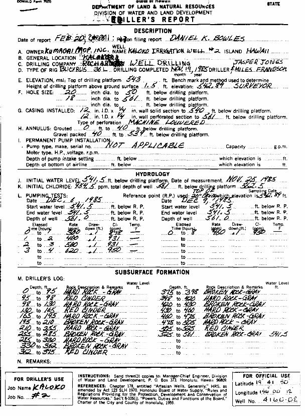
Mobilization to the well site commenced on October 7, 1985. Drilling began on october 17, 1985 and terminated at a depth of 566' (elevation -23') on November 18, 1985. The drill hole diameter was 18 inches. The first water was confirmed at a depth of 541.5 feet.
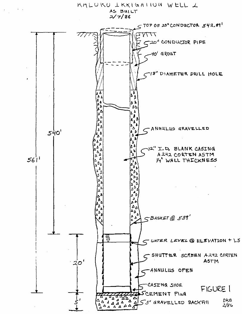
A 40' long dummy of 12" well casing was lowered to the bottom of the bore hole on November 21, 1985. The 12" casing installation (see as-built drawing) was completed on November 27, 1985. The casing was raised 3 feet and rotated 360 degrees to check for straightness and suspended 5 feet off the bottom. Gravel was placed in the well from 566' to 562' and a 1 foot plug of grout was poured to bring the final depth to 561'.
Two pumping tests were performed on December 6 and 9, 1985. On January 8, 1986, the gravelled annulus was completed and a final 40 feet of grout poured.
TEST RESULTS AND WATER QUALITY
The first water taken at a depth of about 8 feet below the water table showed a salinity of about 800 mg/1 chlorides. Subsequent sampling during drilling showed that the chlorides jumped up rapidly to about 950 mg/1.
The rock below water was very permeable and relatively yield (figure 2). Test results indicated that the yield exceeds that of Kaloko #1.
uniform in Kaloko #2
On December 6, 1985, a 4-1/2 hour pumping test was run to determine the yield and salinity at various pumping rates from 300 gpm to a maximum of 650 gpm (figure 3). A second 7-hour test, on December 9, was conducted at an average pumping rate of 450 gpm to simulate the design pumping rate. The detectable drawdown from air line measurements did not exceed 0.15 feet at 450 gpm.
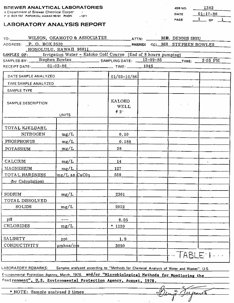
As noted in figure 3 (pump test of 12/9/85) the salinity analysis showed a range of chlorides from 931 to .985 mg/1. The fluctuation of salinity is of little significance and is probably caused by minor variations in pumping rate. The field analysis of 3:00 pm was 970 mg/1 and is the same water subsequently analyzed by the c. Brewer laboratory as 1120 mg/1.
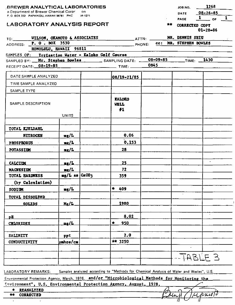
At this high salinity level, there apparently are some variations between field and laboratory technique. The analysis of the sample taken to the laboratory raised a serious question of potential sodium toxicity (see Table 1). A request was made of the lab to recheck the samples of Kaloko #1 and Kaloko #2 water. The corrected and reanalyzed samples are reported in Tables 2, 3 and 4. Table 4 represents the most accurate comparison of water quality from Kaloko #1 and Kaloko #2.

CONCLUSIONS:
The Kaloko 12 was completed in a satisfactory manner as called for by the drilling specifications and the contract can be considered complete. The sites (Kaloko #1 and Kaloko #2) have been cleaned up, the well heads tack-welded shut and painted. Demobilization of both sites is now complete.
The water level in both wells stands at elevation +1.5' and the water quality (Table 4) is essentially identical. It is recommended that the pumping rate for each well not exceed 450 to ~00 gpm, and that the pump intake for each well be set at elevation -10'.
561 1
K 1-\ L U I"'- U J. K K. l <Jl 1-\ I IV l'i W 1:: l L J_ A:;. l3tJ.Il.. T ;:J./7/26
---------
-----
. :2,.0 I
s' +
PIPS
18" DIAM!::Tl:R Pl!Jt.L liOLI::.
A NtHt.LU.S GiRAVl:.\..\...E.D
1:Z.:' I. D. 6\.AN'K. CASING. A .l.'l2 C..O ll."t~~ ASIM Y'i' INA Lt. nu:c...\<.N e..ss
{3A51<E.T@ .5 .31 I
WATE.R LEV/!:L@ 10-L.'~"VATlON + ),5
5\-\UTiaR SC.R!!:IiiN A-..:l.'t.:Z. ~ORTC.N
A5rM
ANNULUS OPEN
F"IGUe.E I

Kt\LO\<J) Wr:. LL ~2. DRILLE-R":> 1-0C:>
t:EPTl-l OE'SC..R..I PTIO t>j '" l"~l!:T
O-Cf5 H A R..D ROC.\£.. - c;, IZ.A Y
9s-- qs IC... ED C..I!I)CE.R..
9B -130 HAR.D Rot.K. -C. RAt
130-lro5' IU. D C. I 1-.l DEft.
liaS- 1'15" 1-\t.Q.D R.CC..K- G It~'(
\Cl.S'-Z,.IC BRo'c:.li~ IU:a. • (;.RII.y'
l.ID- 255 \4~~D ROc.'l.- (;RAY
c.s-s-za~ Bm't.E.Il ~- 't.A v ~85'-310 H 0. "-. D R..c(.l(.. - ~ fi.A '(
3~0 -.3/o~ 81Z0 1C. W ~ex./( - G r<..A Y
!l .. i. -37~ tED C.lt.)OfR_
375"-~a \3RoK.CN Rea.·,f!AY
31'8 -420 RP.R..D ~Ct-\C. ·Gk.At
~-+30 BRC't..~ Ra:..K.· GeAY'
-1-~- 4l.O 1-\ ~ 1'1..'0 RO<,..I£.. - 6(.)1 y
4r.o- 47!'" BlGol'~ R!X:.J(. - C.eA y 475"- 9::15 HAec> e.txJ,L.. - 'ru,y
5"o5' - 5l.S IC..E. D '-IIJ r;e/2..5
SZ.'5- S~(, ~~ 1(, F..N R.ecJl..- G.~IIY
-

~00
50o
40o
?,oo
2.00
/CO
Kt..LOk.O W E.LL ~..: p u ~-~. F>, "'" .,. E:. -;;·r~
GPM
• ·• I ' "\('
/ ~<(, I ' • \'e I
,a~ ~-I ,; •
' ' ....
Cf;oo to:oo 11:00 It!.~"' 1:00 "TtME IN HOL.l.e5
TE.ST 6F 12/'1/$5"
•
TIME(Hd RC.TE (c,pM) CL (11G{L)
e:oo 450 '177
9:oo u 'l31
IO'.CO • '185'
11:00 I q3q
12. NOO/J " q47
~ 1:oo \1 'IH
z.:oo II Cf!J5'
t- '3 :DO • S~@3:o5'
q70 * t-1:DO
i I I
I I
z:.oo
lOCO
'95"0
es-o .
l="IGUR..E 3
Sf'S 81..
' '
BnEWER ANALYTICAL LABORATORIES a O~partment of Brewer Chemical Corpo' P 0 BOX 552 PAPAIKOU, HAWAII 96781 PHON ··1271
LABORATORY ANALYSIS REPORT
JOB NO.
DATE
PAGE
1382
01-17-86 _:_1_ OF
TO: ____ W~IL~S~O~N~O~KA=:!:M~O~T~O~&~A~S.::S.:::O:.::C:.=IA:.:..=.T:.::E:.::S~----A TTN: MR. DENNIS SHIU
ADDRESS: P. 0. BOX 3530 HONOLULU HAWAII 96811
!1~ cc: MR STEPHEN BOWLES
SAMPLES OF: Irrigation Water - Kaloko Golf Course [End of 8 hours pumping)
SAMPLED BY: Stephen Bowles SAMPLING DATE: 12 09-85 TIME: 3·05 PM
RECEIPT DATE: 01 03 86 1046 - TIME:
DATE SAMPLE ANALYZED 01/03-16/86
TIME SAMPLE ANALYZED
SAMPLE TYPE
SAMPLE DESCRIPTION KALOKO WELL
# 2' UNITS
TOTAL KJELDAHL
NITROGEN mg/L 0.10
PHOSPHORUS m~r/L 0.188
POTASSIHM m~r/L 28
CALCIUM m~r/L 14
MAGNESIUM m,./L 127
TOTAL HARDNESS m~r/L as raco., 558
lhv Calculation\
SODIUM m<r/L 2301
TOTAL DISSOLVED
SOLIDS mg/L 2022
pH --- 8.05 CHLORIDES m!r/L * 1120
SALINITY nnt 1.9
CONDUCTIVITY I umhos/c In 3050
1
--TABLE-I---LABORATORY REMARKS: Samples analyzed according to ''Methods for Chemical Analysis of Water and Wastes", U.S.
Envoronmental Proteciion Agency. March, 1976. and/or "Microbiological Methods for Monitoring the >nvironment", U.S. Environmental Protection Agency, August, 1978.
* NOTE: Sample analyzed 2 times

OREWE;R ANALYTICAL LABORATORIES JOB NO. 1382 a 8epartment of Brewer Chemical Corpo m DATE 01·1&·86
PAGE 1 OF 1 0 Q_ BOX 552 PAPAIKOU, HAWAII 96781 PHOt 4-1271
LABORATORY ANALYSIS REPORT ** CORRICT!D COPY 01·28•86
ATTN: HR. DII:RliJIS SHilJ
PHONE: ee: HR. STEPBER BOWLES
To: ____ WI___::_.:LS:_.::_ON.c.!.-, -'OICAMOT"--:_.::__o'--"&"--As::.cs::.coc:..:..::IA:.....:.TE:::.s=--------AooRess: P. o. BOX 3530
HONOLULU, HAWAII 96811 SAMPLES OF: Irdgatioa Water • Italoko Golf Course (End of 8 hours piDiping)
SAMPLED BY: Mr. Stephen Bow1u SAMPLING DATE: 12·09•85 TIME: 3:05 PM RECEIPT DATE : 01·03•86 TIME 1046 :
DATE SAMPLE ANALYZED 01/03·16/86
TIME SAMPLE ANALYZED
SAMPLE TYPE I
ltAI.OltO I i
SAMPLE DESCRIPTION WELL #2
UNITS
' I TOTAL D!tDAIIL
RITROGEif rag/L 0.10 PBOSPBOlUS •g/L 0.188
POTASSitll rav./L 28
CALC I til mg/L 14
MAGN!SIDK •g/L 127
TOTAJ. BA!UlN!SS m11./L as caco .. 558
(bv c.1 .. "1' .. ,\
SODillf rav./L ** 498 TOTAJ. DISSOLVED ..
SOLIDS ra11./L 2022
pH ... A.O'l
CBLOIUDES • .,JL * ll20
SALINI'rY DDt 1.9
CONDUCTIVITY ..s.. 1/ca 10'i0
lt:\BLE ') ~
LABORATORY REMARKS: Samples analyzed according to "Methods for Chemical Analysis of Water and Wastes". U.S.
_[~vironmental Protection Agency. March. 1976. and/or "Microbiological Methods
•nvironment" U.S. Environmental Protection A enc Au ust 1978. * UAHALTZID
.BREVV.ER ANALYTICAL LABORATORIES a,Department of Brewer Chemical Corpr on P. 0. BOX 552 PAPAIKOU, HAWAII 9fl781 PHC ri-4-1271
LABORATORY ANALYSIS REPORT
TO: ______ ~Wl~LS~O~K~,~~~~~O~&~A=S=SOC~IA==TE==S ____________ _ ADDRESS: P. 0 • BOX 3530
HONOLULU HAWAII 96811
SAMPLES OF: Irrigation Water • Ealoko Golf Course
ATTN:
PHONE: cc:
JOB NO. 1268
DATE 08-26-8.5
PAGE 1 OF
** CORRECTED COPY 01-28-86
HR. DENlllS SBIU HR. STEPHEN BOWLES
SAMPLED BY: Mr. Stapball Sowle• SAMPLING DATE: ----"0'-"8.:::.:•0,_,9'-'•'-"8"'-5---TIM E: 1430
RECEIPT DATE : 08•19·85 TIME : 0845
DATE SAMPLE ANALYZED 08/19-21/85
TIME SAMPLE ANALYZED
SAMPLE TYPE
IW.OICO SAMPLE DESCRIPTION WILL
11
UNITS
TOTAL J::JELDAHL
NIT !toeD rag/L 0.06
PROSPBOilUS •RIL 0.153
POTASSIIIl ru/L 28
.. u ......... IHIL 25
KAGJfiSIUM •11./L 72 TOTAL IIAlDRISS •s/L •• CaCOJ 359
(by CalclllatiOD)
SOD I Ill •s/L * 409
TOTAL DISSOLVED
s KR/L 1980
pll 8.02
,..,.y, m11./L * 950
SALINITY ppt 2.0
CONDUCTIVITY )Jraho•/cra ** 3250
-~A'6LE. 3 LABORATORY REMARKS: Samples analyzed according to "Methods for Chemical Analysis of Water and Wastes", U.S.
* REANALYZED ** COilUCTED
1

BnEWER ANALYTICAL LABQr~TORIES a Oepartrnent of Brewer Chemical Corpo' P. 0. BOX 552 PAPAIKOU, HAWAII 96781 PHONE. ,-1271
LABORATORY ANALYSIS REPORT
JOB NO.
OATE
PAGE
1434 01-28•86
_ _:l_ OF
TO: WILSOif, OKAMOTO & ASSOCIATES ATTN: HR. DENNIS SHIV ADDRESS: P. 0. BOX 3530 PHONE: cc I HR. ST!PREK BOWLES
HONOLULU· HAWAII 96811 SAMPLES OF: Irrigation Water ~ laloko Well #1 & #2 SAMPLED BY: Mr. Stephen Bovlea SAMPLING DATE: _________ TIME:
1
RECEIPT DATE: 01•23•86 TIME: ---~11~0:!.!0!...._ ______ ,...--_____ _
DATESAM~LEANALYZED 01/23•24/SE 01/23•24/86 TIME SAMPLE ANALYZED
SAMPLE TYPE
SAMPLE DESCRIPTION JW.Ola) J:AtOm WELL .WELL
#1 #2 UNITS 12/0!J/85
SOD I !If mJZ./L 242 293
CONDUCTIVITY b.boa/cm ]210 ,,on
CHLORIDE .._/L 910 905 -
RESAMPLIS • NO CHARGES
.=TABL~-4
. ABORATORY REMARKS: Samples analyzed according to "Methods for Chemical Analysis of Water and Wastes", U.S .
c,v"onmental Protection Agency. March. 1976. and/or "Microbiological Methods
Environment", U.S. Environmental Protection Agency. August. 1978. for Monitoring the
-