© siemens ag 2009 monitoring and control devices 7 · siemens lv 1 · 2009 7 7/2 introduction...
TRANSCRIPT
Siemens LV 1 · 2009
77/2 Introduction
SIMOCODE 3UF Motor Management and Control Devices
7/6 SIMOCODE pro 3UF7 motor management and control devices
7/16 3UF18 current transformers for overload protection
LOGO! Logic Modules1)
7/17 General data7/18 LOGO! Modular basic versions7/19 LOGO! Modular pure versions7/20 LOGO! Modular expansion modules7/21 LOGO! CM EIB/KNX
communication modules7/22 AS-Interface connections for LOGO!7/23 AccessoriesCh.11 LOGO! Power7/24 LOGO! Contact7/25 LOGO! Software
3RP, 3RT19 Timing Relays7/26 3RP15 timing relays
in industrial enclosure, 22.5 mm7/32 3RP20 timing relays, 45 mm7/36 3RT19 16, 3RT19 26 timing relays
for mounting onto contactors
Monitoring Relays3UG Monitoring Relays for Electrical and Additional Measurements
7/38 Line monitoring7/42 Voltage monitoring7/44 Current monitoring7/46 Power factor and active current monitoring
Residual Current Monitoring:7/48 - Residual current monitoring relays7/50 - Summation current transformers
Insulation Monitoring:7/51 - For ungrounded AC networks7/52 - For ungrounded DC networks
Level Monitoring: 7/53 - Level monitoring relays7/55 - Level monitoring sensors7/56 Speed monitoring
3RS10, 3RS11 Temperature Monitoring Relays7/58 Relays, analogically adjustable, for 1 sensor7/61 Relays, digitally adjustable, for 1 sensor7/64 Relays, digitally adjustable for up to 3 sensors
3RN1 Thermistor Motor Protection7/66 For PTC sensors
3TK28 Safety Relays7/70 General data7/71 With electronic enabling circuits7/75 With relay enabling circuits7/80 With contactor relay enabling circuits7/82 With special functions
3RK3 Modular Safety System7/84 General data7/85 Modules7/87 Accessories
Interface Converters 7/88 3RS17 interface converters
1) See Catalog ST 70 · 2009 "Products for Totally Integrated Automation and Micro Automation".
Monitoring andControl Devices
LV1_09_Gesamt_EN.book Seite 1 Mittwoch, 11. Februar 2009 3:54 15
© Siemens AG 2009

Monitoring and Control Devices
Introduction
7/2 Siemens LV 1 · 2009
7
■ Overview
The advantages at a glance
Type PageSIMOCODE 3UF motor management and control devicesSIMOCODE pro 3UF7 • Compact, modular design
• Unique flexibility in terms of functionality and hardware configuration
• Wide functional range from the distributed I/O system to the autonomous motor management system
• All control functions from the direct-on-line starter to the pole-changing switch with reversing contactor
• All motor sizes• Integration in all PROFIBUS-capable automation systems• Application in low-voltage controlgear for motor control
centers in the process industry• Increases plant availability• Saves costs during construction, commissioning and
operation of the plant• Extensive data of the motor feeder available everywhere on
the PROFIBUS• All protection, monitoring and control functions for the motor
feeder in a single system
3UF7 7/6
3UF18 current transformers for overload protection
• Protection transformer for activating overload relays or for use with SIMOCODE 3UF
• Ensures proportional current transfer up to a multiple of the primary rated current
3UF18 7/16
LOGO! logic modulesLOGO! logic modules • Compact, user-friendly and low-cost solution for simple
control tasks• Universal:
- Building installation and wiring (lighting, shutters, awnings, doors, access control, barriers, ventilation systems ...)
- Control cabinet installation- Machine and device construction (pumps, small presses,
compressors, hydraulic lifts, conveyors ...) - Special controls for conservatories and greenhouses- Signal preprocessing for other controllers
• Flexible expansion depending on the application
LOGO! Modular basic versions • With display, pushbuttons and an interface for connecting expansion units
6ED1 052-1 7/18
LOGO! Modular pure versions • Without display and pushbuttons but with an interface for connecting expansion units
6ED1 052-2 7/19
LOGO! Modular expansion modules • For connection to LOGO! Modular basic versions with digital inputs and outputs or analog inputs and outputs
6ED1 055-1 7/20
LOGO! Modular communication modules • For integrating LOGO! in an instabus KNX EIB system or as an AS-Interface slave
6BK1 700,3RK1 400
7/21,7/22
LOGO! Power • Power supply for converting the mains voltage of 100 ... 240 V AC into an operational voltage of 24 V DC or 12 V DC
6EP1 3 Ch. 11
LOGO! Contact • Switching module for switching resistive loads and motors directly
6ED1 057-4 7/24
LOGO! Software • For switchgear program generation on the PC 6ED1 058 7/25
3RP, 3RT19 timing relays3RP15 timing relays in industrial enclosure, 22.5 mm
• Low-cost solution with monofunctions such as response delay, off-delay, clock-pulse, wye-delta function and multifunction
3RP15 7/26
• Wide range voltage designs
3RP20 timing relay, 45 mm • The solution for small mounting depths 3RP20 7/32• The low mounting height reduces the tier spacing
3RT19 16, 3RP19 26 timing relays for mounting onto contactors
• Saves space because the relay is mounted onto the contactor
3RT1916, 3RT19 26
7/36
• Wiring advantages thanks to direct contacting to the contactor
3UF7 3RP156ED1 052
LV1_09_Gesamt_EN.book Seite 2 Mittwoch, 11. Februar 2009 3:54 15
© Siemens AG 2009

Monitoring and Control Devices
Introduction
7/3Siemens LV 1 · 2009
77
The advantages at a glance
Type Page
3UG monitoring relays for electrical and additional measurementsLine monitoringPhase sequence • Low-cost solution for monitoring the phase sequence 3UG45 11 7/38
Phase sequence, phase failure, phase unbalance • Wide voltage range from 160 ... 690 V 3UG45 12 7/38
Phase sequence, phase failure, phase unbalance and undervoltage
• Analogically adjustable• Wide voltage range from 160 ... 690 V
3UG45 13 7/38
• Digitally adjustable with LCDfor indication of ACTUAL value and device status
• Wide voltage range from 160 ... 690 V
3UG46 14 7/38
Phase sequence, phase failure, phase unbalance over limit values, overvoltage and undervoltage
• Digitally adjustable with LCDfor indication of ACTUAL value and device status
• Wide voltage range from 160 ... 690 V
3UG46 15 7/38
Phase sequence, phase and N conductor failure, phase unbalance over limit values, overvoltage and undervoltage
3UG46 16 7/38
Automatic correction of the direction of rotation in case of wrong phase sequence, phase failure, phase unbalance, overvoltage and undervoltage
3UG46 17 7/38
Automatic correction of the direction of rotation in case of wrong phase sequence, phase and N conductor failure, phase unbalance, overvoltage and undervoltage
3UG46 18 7/38
Voltage monitoringVoltage monitoring with internal power supply for overvoltage and undervoltage
• Digitally adjustable with LCDfor indication of ACTUAL value and device status
• Wide measuring ranges• Version for wide voltage range
3UG46 33 7/42
Voltage monitoring with auxiliary voltage for overvoltage and undervoltage
3UG46 31,3UG46 32
7/42
Current monitoringCurrent monitoring with auxiliary voltage for overshoot and undershoot
• Digitally adjustable with LCDfor indication of ACTUAL value and device status
• Wide measuring ranges• Version for wide voltage range
3UG46 21,3UG46 22
7/44
Power factor and active current monitoring (motor load monitoring)Power factor and active current monitoring with internal power supply for overshoot, undershoot or window monitoring
• For load monitoring over the entire torque range• Digitally adjustable with LCD
for indication of ACTUAL value and device status• Wide voltage range from 90 ... 690 V
3UG46 41 7/46
Residual current monitoringResidual current monitoring relays • Digitally adjustable with LCD
for indication of ACTUAL value and device status• Adjustable threshold values for warning and disconnection• For plant monitoring• Wide voltage range from 90 ... 690 V
3UG46 24 7/48
Summation current transformers • For detection of fault currents in machines and plants 3UL22 7/50
Insulation monitoringMonitoring of the insulation resistance for ungrounded AC or DC networks from 1 ... 110 kΩ
• Test button 3UG30 81, 3UG30 82
7/51, 7/52• With or without memory• Switchable measuring range
Level monitoringFill level and resistance • As single-step or two-step controls for inlet or outlet monitor-
ing of conducting liquids or as resistance threshold switch3UG45 01 7/53
• Adjustable, wide range from 2 ... 200 kΩ• UNDER/OVER adjustable
Level monitoring sensors • Wire, rod or bow electrodes 3UG32 7/55
Speed monitoringSpeed monitoring for overshoot, undershoot or window monitoring
• Digitally adjustable with LCD for indication of ACTUAL value and device status
• Wide measuring ranges• Version for wide voltage range• Together with a sensor for monitoring continuous pulses• With or without memory• Adjustable delay times
3UG46 51 7/56
3UG45 11 3UG46 16 3UG46 33
LV1_09_Gesamt_EN.book Seite 3 Mittwoch, 11. Februar 2009 3:54 15
© Siemens AG 2009

Monitoring and Control Devices
Introduction
7/4 Siemens LV 1 · 2009
7
The advantages at a glance
Type Page
3RS10, 3RS11 temperature monitoring relaysFor monitoring the temperatures of solids, liquids, and gasesRelays, analog adjustable, for 1 sensor • Separate versions for overshoot and undershoot 3RS10,
3RS117/58
• For simple monitoring tasks• For PT100 or thermoelements J and K• Variable hysteresis
Relays, digitally adjustable, for 1 sensor • For two- or three-point closed-loop controls 3RS10, 3RS11, 3RS20,3RS21
7/58• For monitoring heat generation plants• For PT100/1000, KTY83/84, NTC or thermoelements
type J, K, T, E, N, R, S, B
Relays, digitally adjustable for up to 3 sensors • For simultaneously monitoring several sensors 3RS10 7/64• Especially suited for monitoring motor winding temperatures• For PT100/1000, KTY83/84, NTC
3RN1 thermistor motor protectionFor PTC sensors • Relays for monitoring motor winding temperatures with type
A PTC sensors3RN1 7/66
• Integrated with ATEX approval• Closed-circuit principle• Depending on the version: With short-circuit and open-circuit
detection, protection against voltage failure, manual/auto/remote RESET, 1 CO, 1 NO + 1 NC, 2 CO, 1 NO + 1 CO or 2 CO hard gold-plating
3TK28 safety relaysWith electronic enabling circuits • Permanent function checking
• No wear because switched electronically• High switching frequency• Long electrical endurance• Evaluation of solid-state sensors• Sensor lead up to max. 2000 m• Cascading possible• Insensitive to vibrations and dirt• Compact design, low weight• Approved for the world market
3TK28 4 7/71
With relay enabling circuits • Compact design• Floating safe outputs• Also suitable for press and punch controls• Can be used up to an ambient temperature of max. 70 °C
3TK28 2, 3TK28 3
7/75
With contactor relay enabling circuits • Enabling circuits, floating• AC-15/DC-13 switching capacity• Protective separation• Long mechanical and electrical endurance• Certified as a complete unit• Fault minimization and cost reduction through factory wiring• Low installation costs
3TK28 5 7/80
With special functions • Floating safe outputs• Signaling outputs for status and diagnostic signals• Safe standstill monitoring
3TK28 1 7/82
3TK283RN13RS10
,
LV1_09_Gesamt_EN.book Seite 4 Mittwoch, 11. Februar 2009 3:54 15
© Siemens AG 2009

Monitoring and Control Devices
Introduction
7/5Siemens LV 1 · 2009
77
■ Options
On the following pages you will find selection tables for monitor-ing and control devices.
"Increased safety" type of protection EEx e/d according to ATEX directive 94/9/EC
The communication-capable, modularly designed SIMOCODE pro motor management system (SIRIUS Motor Man-agement and Control Devices) protects motors of types of pro-tection EEx e and EEx d in potentially explosive areas.
ATEX approval for operation in areas subject to explosion hazard
The SIRIUS 3RN1 thermistor motor protection relay for PTC sen-sors is certified according to ATEX Ex II (2) G and GD for gases and dust.
The SIRIUS SIMOCODE pro 3UF7 motor management system is certified for the protection of motors in areas subject to explosion hazard according to• ATEX Ex I (M2); equipment group I, category M2 (mining) • ATEX Ex II (2) GD; equipment group II, category 2 in area GD.
See "Appendix" --> "Standards and approvals" --> "Type over-view of approved devices for potentially explosive areas (ATEX explosion protection)".
The advantages at a glance
Type Page3RK3 modular safety systemsFreely configurable, modular safety relays • More functionality and flexibility through freely configurable
safety logic• For all safety applications thanks to compliance with the
highest safety requirements (Category 4 according to EN 954-1, Performance Level e according to ISO 13849-1 or SIL3 according to IEC 62061)
• Can be used globally• Modular hardware configuration• Parameterization by means of software instead of wiring• Removable terminals for greater plant availability
3RK3 7/84
3RS17 interface convertersConverters for standard signals and non-standard variables
• All terminals protected against polarity reversing and over-voltage up to 30 V
• For electrical isolation and conversion of analog signals
• Short-circuit resistant outputs• From 6.2 mm width• Switchable multi-range converters• Versions with manual/automatic switch for setpoint selection• Versions for conversion of analog variables into frequency
3RS17 7/88
3RS173RK3
Screw terminals
Spring-type terminals
The terminals are indicated in the selection and ordering data by orange backgrounds.
LV1_09_Gesamt_EN.book Seite 5 Mittwoch, 11. Februar 2009 3:54 15
© Siemens AG 2009

SIMOCODE 3UF Motor Management and Control Devices
SIMOCODE pro 3UF7 motor management and control devices
7/6 Siemens LV 1 · 2009
7
■ Overview
SIMOCODE pro V with current/voltage measuring module, expansion modules and operator panel with display
SIMOCODE pro is a flexible, modular motor management sys-tem for motors with constant speeds in the low-voltage perfor-mance range. It optimizes the connection between I&C and motor feeder, increases plant availability and allows significant savings to be made for startup, operation and maintenance of a system.
When SIMOCODE pro is installed in the low-voltage switch-board, it is the intelligent interface between the higher-level au-tomation system and the motor feeder and includes the following:• Multifunctional, solid-state full motor protection which is inde-
pendent of the automation system• Integrated control functions instead of hardware for the motor
control• Detailed operating, service and diagnostics data• Open communication through PROFIBUS DP, the standard for
fieldbus systems
SIMOCODE ES is the software package for SIMOCODE pro parameterization, start-up and diagnostics.
■ Benefits
General customer benefits• Integrating the whole motor feeder into the process control by
means of a bus significantly reduces the wiring outlay be-tween the motor feeder and PLC
• Decentralization of the automated processes by means of configurable control and monitoring functions in the feeder saves resources in the automation system and ensures full functionality and protection of the feeder even if the I&C or bus system fails
• The acquisition and monitoring of operational, service and di-agnostics data in the feeder and process control system in-creases plant availability as well as maintenance and service-friendliness
• The high degree of modularity allows users to perfectly imple-ment their plant-specific requirements for each motor feeder
• The SIMOCODE pro system offers functionally graded and space-saving solutions for each customer application
• The replacement of the control circuit hardware with inte-grated control functions decreases the number of hardware components and wiring required and in this way limits stock keeping costs and potential wiring errors
• The use of solid-state full motor protection permits better utili-zation of the motors and ensures long-term stability of the trip-ping characteristic and reliable tripping even after years of service
Multifunctional, solid-state full motor protection for rated motor currents up to 820 A
SIMOCODE pro offers comprehensive protection of the motor feeder by means of a combination of different, multi-step and de-layable protection and monitoring functions:• Inverse-time delayed solid-state overload protection
(Class 5 ... 40)• Thermistor motor protection• Phase failure / unbalance protection• Stall protection• Monitoring of adjustable limit values for the motor current• Voltage and power monitoring• Monitoring of the power factor (motor idling/load shedding)• Ground-fault monitoring • Temperature monitoring, e. g. over PT100/PT1000• Monitoring of operating hours, downtime and number of starts
etc.
Recording of measuring curves
SIMOCODE pro can record measuring curves and therefore is able, for example, to present the progression of motor current during motor start-up.
Flexible motor control implemented with integrated control functions (instead of comprehensive hardware interlocks)
Many predefined motor control functions have already been in-tegrated into SIMOCODE pro, including all necessary logic op-erations and interlocks:• Overload relays• Direct-on-line and reversing starters• Star/delta starters (also with direction reversal)• Two speeds, motors with separate windings (pole-changing
switch); also with direction reversal • Two speeds, motors with separate Dahlander windings (also
with direction reversal) • Positioner actuation • Solenoid valve actuation • Actuation of a circuit breaker• Soft starter actuation (also with direction reversal)
These control functions are predefined in SIMOCODE pro and can be freely assigned to the inputs and outputs of the device (including PROFIBUS DP).
These predefined control functions can also be flexibly adapted to each customized configuration of a motor feeder by means of freely configurable logic modules (truth tables, counters, timers, edge evaluation ...) and with the help of standard functions (power failure monitoring, emergency start, external faults ...), without additional auxiliary relays being necessary in the control circuit.
SIMOCODE pro makes a lot of additional hardware and wiring in the control circuit unnecessary which results in a high level of standardization of the motor feeder in terms of its design and cir-cuit diagrams.
LV1_09_Gesamt_EN.book Seite 6 Mittwoch, 11. Februar 2009 3:54 15
© Siemens AG 2009

SIMOCODE 3UF Motor Management and Control Devices
SIMOCODE pro 3UF7motor management and control devices
7/7Siemens LV 1 · 2009
77
Detailed operational, service and diagnostics data
SIMOCODE pro makes different operational, service and diag-nostics data available and helps to detect potential faults in time and to prevent them by means of preventative measures. In the event of a malfunction, a fault can be diagnosed, localized and rectified very quickly – there are no or very short downtimes.
Operating data• Motor switching state derived from the current flow in the main
circuit• All phase currents• All phase voltages• Active power, apparent power and power factor• Phase unbalance and phase sequence• Time to trip• Motor temperature• Remaining cooling time etc.
Service data• Motor operating hours• Motor stop times• Number of motor starts• Number of overload trips• Consumed power• Internal comments stored in the device etc.
Diagnostics data• Numerous detailed early warning and fault messages• Internal device fault logging with time stamp• Time stamping of freely selectable status, alarm or fault mes-
sages etc.
Communication
SIMOCODE pro is equipped with an integral PROFIBUS DP in-terface (SUB-D or terminal connection) and can therefore re-place all individual wiring (including marshalling racks), which would usually be required for exchanging data with the higher-level automation system, with a single 2-wire cable.
SIMOCODE pro supports among other things: • Baud rates up to 12 Mbit/s • Automatic baud rate detection• Communication with up to 3 masters• Time synchronization over PROFIBUS (SIMATIC S7)• Time stamp with high timing precision (SIMATIC S7)• Cyclic services (DPV0) and acyclic services (DPV1)• DPV1 communication after the Y-Link etc.
Communication: • For SIMOCODE pro motor management and control devices
with communication function see page 7/8 onwards.• For accessories, see page 7/11.• For more information see Chapter 12 "Planning and Configu-
ration with SIRIUS".
SIMOCODE pro combines all the necessary functions for the motor feeder in a compact system.
*�-%.
%%�1
2
�3� �3�
4�4�4�
�5�
�3� �3�
%
�6�
���� �� �� 7����� �� ��
!"#�$89��!
7 ��������� ���0��� �
8��� ���
#�����������
�$�#7#�(���
7���� ���� �+�
!���� �����������:�/�����;����������;������� ����� ����<<<=
����� �����:�� <���������0>������ ,��0=
7��� �� �����:����������;���/� �;���0����� �����
> ����� �������=
- ���������/�
"�����
LV1_09_Gesamt_EN.book Seite 7 Mittwoch, 11. Februar 2009 3:54 15
© Siemens AG 2009

SIMOCODE 3UF Motor Management and Control Devices
SIMOCODE pro 3UF7 motor management and control devices
7/8 Siemens LV 1 · 2009
7
■ Application
SIMOCODE pro is often used for automated processes where plant downtimes are very expensive (e. g. steel or cement indus-try) and where it is important to prevent plant downtimes through detailed operational, service and diagnostics data or to localize the fault very quickly in the event of a fault.
SIMOCODE pro is modular and space-saving and suited espe-cially for operation in motor control centers in the process indus-try and for power plant technology.
Applications
Protection and control of motors• In hazardous areas for types of protection
EEx e/d according to ATEX directive 94/9/EC see "Appendix" --> "Standards and approvals" --> "Type over-view of approved devices for explosion-protected areas (ATEX Explosion Protection)".
• With heavy starting (paper, cement, metal and water industries)
• In high-availability plants (chemical, oil, raw material process-ing industry, power plants)
Industries
Today, SIMOCODE pro is mainly used in the chemical (incl. oil and gas), steel, water, paper, pharmaceutical, cement, and glass industry. It is also used for applications in power plants and large diamond, gold and platinum mines. Based on the ex-perience made with the predecessor system SIMOCODE-DP, SIMOCODE pro has been tailored even more specifically to the requirements of these industries.
An essential requirement in these industries is the availability of the motors and thus the availability of the whole process. Plant downtimes caused by faults frequently result in high costs. For this reason, it is very important to detect potential faults early on and to initiate targeted countermeasures. SIMOCODE pro offers users an up-to-date motor management system based on years of experience.
■ Selection and ordering data
Version Current setting
Width DT Screw terminals PU (UNIT, SET, M)
PS* PG Weight per PU approx.
Order No. Price per PUA mm kg
SIMOCODE pro
3UF7 000-1A.00-0
SIMOCODE pro C, basic units 1PROFIBUS DP interface, 12 Mbit/s, RS 4854 I/3 O freely assignable, input for thermistor connection, monostable relay outputs,rated control supply voltage Us:
• 24 V DC A 3UF7 000-1AB00-0 1 1 unit 131 0.350
• 110 ... 240 V AC/DC A 3UF7 000-1AU00-0 1 1 unit 131 0.350
3UF7 010-1A.00-0
SIMOCODE pro V, basic units 2PROFIBUS DP interface, 12 Mbit/s, RS 4854 I/3 O freely assignable, input for thermistor connection, monostable relay outputs,can be expanded with expansion modules,rated control supply voltage Us:
• 24 V DC A 3UF7 010-1AB00-0 1 1 unit 131 0.350
• 110 ... 240 V AC/DC A 3UF7 010-1AU00-0 1 1 unit 131 0.350
3UF7 100-1AA00-0
Current measuring modules
Straight-throughtransformers
0.3 ... 3 45 A 3UF7 100-1AA00-0 1 1 unit 131 0.1002.4 ... 25 45 A 3UF7 101-1AA00-0 1 1 unit 131 0.150
10 ... 100 55 A 3UF7 102-1AA00-0 1 1 unit 131 0.35020 ... 200 120 A 3UF7 103-1AA00-0 1 1 unit 131 0.600
Busbar connections 20 ... 200 120 A 3UF7 103-1BA00-0 1 1 unit 131 1.00063 ... 630 145 A 3UF7 104-1BA00-0 1 1 unit 131 1.750
* You can order this quantity or a multiple thereof.
LV1_09_Gesamt_EN.book Seite 8 Mittwoch, 11. Februar 2009 3:54 15
© Siemens AG 2009

SIMOCODE 3UF Motor Management and Control Devices
SIMOCODE pro 3UF7motor management and control devices
7/9Siemens LV 1 · 2009
77
* You can order this quantity or a multiple thereof.
SIMOCODE pro
3UF7 110-1AA00-0
Current/voltage measuring modules
Voltage measuring up to 690 V if required in connection with a decoupling module
Straight-throughtransformers
0.3 ... 3 45 A 3UF7 110-1AA00-0 1 1 unit 131 0.1502.4 ... 25 45 A 3UF7 111-1AA00-0 1 1 unit 131 0.200
10 ... 100 55 A 3UF7 112-1AA00-0 1 1 unit 131 0.40020 ... 200 120 A 3UF7 113-1AA00-0 1 1 unit 131 0.700
Busbar connections 20 ... 200 120 A 3UF7 113-1BA00-0 1 1 unit 131 1.00063 ... 630 145 A 3UF7 114-1BA00-0 1 1 unit 131 1.750
3UF7 150-1AA00-0
Decoupling modulesFor connecting upstream from a current/voltage measuring module on the system interface when using voltage detection in non-earthed networks
A 3UF7 150-1AA00-0 1 1 unit 131 0.150
3UF7 200-1AA00-0
Operator panelsInstallation in control cabinet door or front plate, for plugging into basic unit, 10 LEDs for status indica-tion and user-assignable buttons for controlling the motor
A 3UF7 200-1AA00-0 1 1 unit 131 0.100
3UF7 210-1AA00-0
Operator panels with display for SIMOCODE pro V1)
Installation in control cabinet door or front plate, for plugging into basic unit 2, 7 LEDs for status indica-tion and user-assignable buttons for controlling the motor, multilingual display, e. g. for indication of measured values, status information or fault messages
} 3UF7 210-1AA00-0 1 1 unit 131 0.150
Version Current setting
Width DT Screw terminals PU (UNIT, SET, M)
PS* PG Weight per PU approx.
Order No. Price per PUA mm kg
1) Only possible with basic unit 2, product version E03 and higher (from 12/2006).
LV1_09_Gesamt_EN.book Seite 9 Mittwoch, 11. Februar 2009 3:54 15
© Siemens AG 2009
SIMOCODE 3UF Motor Management and Control Devices
SIMOCODE pro 3UF7 motor management and control devices
7/10 Siemens LV 1 · 2009
7
Version DT Screw terminals PU (UNIT, SET, M)
PS* PG Weight per PU approx.
Order No. Price per PU kg
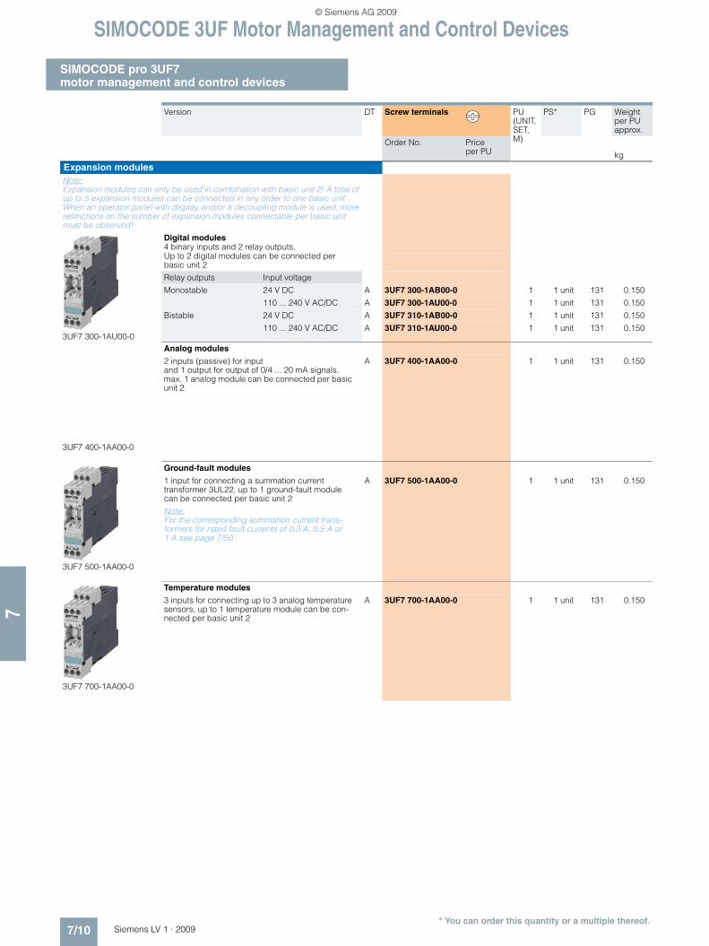
Expansion modulesNote:Expansion modules can only be used in combination with basic unit 2! A total of up to 5 expansion modules can be connected in any order to one basic unit. When an operator panel with display and/or a decoupling module is used, more restrictions on the number of expansion modules connectable per basic unit must be observed!
3UF7 300-1AU00-0
Digital modules4 binary inputs and 2 relay outputs, Up to 2 digital modules can be connected per basic unit 2
Relay outputs Input voltage
Monostable 24 V DC A 3UF7 300-1AB00-0 1 1 unit 131 0.150
110 ... 240 V AC/DC A 3UF7 300-1AU00-0 1 1 unit 131 0.150
Bistable 24 V DC A 3UF7 310-1AB00-0 1 1 unit 131 0.150
110 ... 240 V AC/DC A 3UF7 310-1AU00-0 1 1 unit 131 0.150
3UF7 400-1AA00-0
Analog modules
2 inputs (passive) for input and 1 output for output of 0/4 ... 20 mA signals, max. 1 analog module can be connected per basic unit 2
A 3UF7 400-1AA00-0 1 1 unit 131 0.150
3UF7 500-1AA00-0
Ground-fault modules
1 input for connecting a summation current transformer 3UL22, up to 1 ground-fault module can be connected per basic unit 2
Note: For the corresponding summation current trans-formers for rated fault currents of 0.3 A, 0.5 A or 1 A see page 7/50.
A 3UF7 500-1AA00-0 1 1 unit 131 0.150
3UF7 700-1AA00-0
Temperature modules
3 inputs for connecting up to 3 analog temperature sensors, up to 1 temperature module can be con-nected per basic unit 2
A 3UF7 700-1AA00-0 1 1 unit 131 0.150
* You can order this quantity or a multiple thereof.
LV1_09_Gesamt_EN.book Seite 10 Mittwoch, 11. Februar 2009 3:54 15
© Siemens AG 2009

SIMOCODE 3UF Motor Management and Control Devices
SIMOCODE pro 3UF7motor management and control devices
7/11Siemens LV 1 · 2009
77
■ Accessories
Version DT Order No. Price per PU
PU (UNIT, SET, M)
PS* PG Weight per PU approx.
kg
Connection cables (essential accessory)
3UF7 932-0AA00-0
Connection cablesIn different lengths for connecting basic unit, cur-rent measuring module, current/voltage measuring module, operator panel or expansion modules or decoupling module:
• Length 0.025 m (flat)Note: Only suitable for connecting basic unit 2 to its expansion modules or for connecting expan-sion modules to each other; only when the front plates finish at the same height!
A 3UF7 930-0AA00-0 1 1 unit 131 0.010
• Length 0.1 m (flat) A 3UF7 931-0AA00-0 1 1 unit 131 0.010• Length 0.3 m (flat) A 3UF7 935-0AA00-0 1 1 unit 131 0.020• Length 0.5 m (flat) A 3UF7 932-0AA00-0 1 1 unit 131 0.020
• Length 0.5 m (round) A 3UF7 932-0BA00-0 1 1 unit 131 0.050• Length 1.0 m (round) A 3UF7 937-0BA00-0 1 1 unit 131 0.100• Length 2.5 m (round) A 3UF7 933-0BA00-0 1 1 unit 131 0.150
PC cables and adapters
3UF7 940-0AA00-0
For PC/PG communication with SIMOCODE prothrough the system interface, for connecting to the serial interface of the PC/PG
A 3UF7 940-0AA00-0 1 1 unit 131 0.150
USB/serial adaptersTo connect an RS 232 PC cable to the USB port of a PC, we recommend using modular safety system 3RK3, soft starter 3RW44, ET 200S/ECOFAST/ET 200pro motor starter, AS-i safety monitor, AS-i analyzer in conjunction with SIMOCODE pro 3UF7
B 3UF7 946-0AA00-0 1 1 unit 131 0.150
Memory modules
3UF7 900-0AA00-0
The memory module enables the complete param-eter assignment of a system to be saved and transferred to a new system, e. g. when a device is replaced, without the need for additional aids or detailed knowledge of the the system interface
A 3UF7 900-0AA00-0 1 1 unit 131 0.010
Interface covers
3UF7 950-0AA00-0
For system interface A 3UF7 950-0AA00-0 1 5 units 131 0.100
Addressing plugs
3UF7 910-0AA00-0
For assigning the PROFIBUS addresses without using a PC/PG On SIMOCODE pro through the system interface
A 3UF7 910-0AA00-0 1 1 unit 131 0.030
Door adapters
3UF7 920-0AA00-0
For external connection of the system interfaceOutside, for example, a control cabinet
A 3UF7 920-0AA00-0 1 1 unit 131 0.030
Adapters for operator panel
3UF7 922-0AA00-0
The adapter enables the smaller 3UF7 20 operator panel from SIMOCODE pro to be used in a front panel cutout in which previously, e. g. after a change of system, a larger 3UF5 2 operator panel from SIMOCODE-DP had been used; degree of protection IP54
A 3UF7 922-0AA00-0 1 1 unit 131 0.150
* You can order this quantity or a multiple thereof.
LV1_09_Gesamt_EN.book Seite 11 Mittwoch, 11. Februar 2009 3:54 15
© Siemens AG 2009
SIMOCODE 3UF Motor Management and Control Devices
SIMOCODE pro 3UF7 motor management and control devices
7/12 Siemens LV 1 · 2009
7
Version DT Order No. Price per PU
PU (UNIT, SET, M)
PS* PG Weight per PU approx.
kg
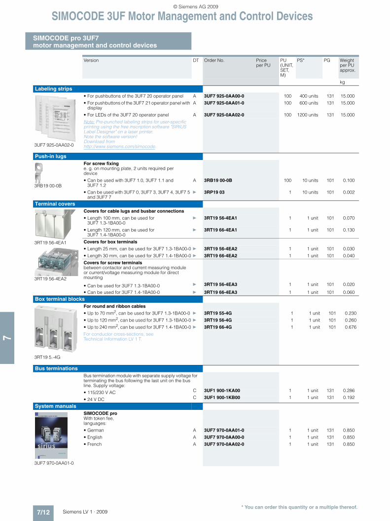
Labeling strips
3UF7 925-0AA02-0
• For pushbuttons of the 3UF7 20 operator panel A 3UF7 925-0AA00-0 100 400 units 131 15.000
• For pushbuttons of the 3UF7 21 operator panel with display
A 3UF7 925-0AA01-0 100 600 units 131 15.000
• For LEDs of the 3UF7 20 operator panel A 3UF7 925-0AA02-0 100 1200 units 131 15.000
Note: Pre-punched labeling strips for user-specific printing using the free inscription software "SIRIUS Label Designer" on a laser printer. Note the software version! Download from http://www.siemens.com/simocode.
Push-in lugs
3RB19 00-0B
For screw fixinge. g. on mounting plate, 2 units required per device
• Can be used with 3UF7 1.0, 3UF7 1.1 and 3UF7 1.2
A 3RB19 00-0B 100 10 units 101 0.100
• Can be used with 3UF7 0, 3UF7 3, 3UF7 4, 3UF7 5 and 3UF7 7
} 3RP19 03 1 10 units 101 0.002
Terminal covers
3RT19 56-4EA1
3RT19 56-4EA2
Covers for cable lugs and busbar connections
• Length 100 mm, can be used for 3UF7 1.3-1BA00-0
} 3RT19 56-4EA1 1 1 unit 101 0.070
• Length 120 mm, can be used for 3UF7 1.4-1BA00-0
} 3RT19 66-4EA1 1 1 unit 101 0.130
Covers for box terminals
• Length 25 mm, can be used for 3UF7 1.3-1BA00-0 } 3RT19 56-4EA2 1 1 unit 101 0.030
• Length 30 mm, can be used for 3UF7 1.4-1BA00-0 } 3RT19 66-4EA2 1 1 unit 101 0.040
Covers for screw terminalsbetween contactor and current measuring module or current/voltage measuring module for direct mounting
• Can be used for 3UF7 1.3-1BA00-0 } 3RT19 56-4EA3 1 1 unit 101 0.020
• Can be used for 3UF7 1.4-1BA00-0 } 3RT19 66-4EA3 1 1 unit 101 0.060
Box terminal blocks
3RT19 5.-4G
For round and ribbon cables
• Up to 70 mm2, can be used for 3UF7 1.3-1BA00-0 } 3RT19 55-4G 1 1 unit 101 0.230
• Up to 120 mm2, can be used for 3UF7 1.3-1BA00-0 } 3RT19 56-4G 1 1 unit 101 0.260
• Up to 240 mm2, can be used for 3UF7 1.4-1BA00-0 } 3RT19 66-4G 1 1 unit 101 0.676
For conductor cross-sections, see Technical Information LV 1 T.
Bus terminationsBus termination module with separate supply voltage for terminating the bus following the last unit on the bus line. Supply voltage:
• 115/230 V AC C 3UF1 900-1KA00 1 1 unit 131 0.286
• 24 V DC C 3UF1 900-1KB00 1 1 unit 131 0.192
System manuals
3UF7 970-0AA01-0
SIMOCODE proWith token fee, languages:
• German A 3UF7 970-0AA01-0 1 1 unit 131 0.850
• English A 3UF7 970-0AA00-0 1 1 unit 131 0.850
• French A 3UF7 970-0AA02-0 1 1 unit 131 0.850
* You can order this quantity or a multiple thereof.
LV1_09_Gesamt_EN.book Seite 12 Mittwoch, 11. Februar 2009 3:54 15
© Siemens AG 2009

SIMOCODE 3UF Motor Management and Control Devices
SIMOCODE pro 3UF7motor management and control devices
7/13Siemens LV 1 · 2009
77
Version DT Order No. Price per PU
PU (UNIT, SET, M)
PS* PG Weight per PU approx.
kg
PCS 7 function block library for SIMOCODE pro
3UF7 982-0AA00-0
For integrating SIMOCODE pro into the PCS 7 process control system
• PCS 7 function block library for SIMOCODE pro, V6.0Scope of supply: AS modules and faceplates for integrating SIMOCODE pro into the PCS 7 process control system, for PCS 7 Version V6.0 engineering software for one engineering station (single license) including runtime software for execution of the AS module in an automation system (single license), English/French/German,Type of delivery: CD incl. electronic documentation
A 3UF7 982-0AA00-0 1 1 unit 131 0.240
• PCS 7 function block library for SIMOCODE pro, V6.1Scope of supply: AS modules and faceplates for integrating SIMOCODE pro into the PCS 7 process control system, for PCS 7 Version V6.1 engineering software for one engineering station (single license) including runtime software for execution of the AS module in an automation system (single license), English/French/German,Type of delivery: CD incl. electronic documentation
A 3UF7 982-0AA02-0 1 1 unit 131 0.240
• PCS 7 SIMOCODE pro function block library, V7.0 Scope of supply:AS modules and faceplates for integrating SIMOCODE pro into the PCS 7 process control system,for PCS 7 Version V7.0engineering software for one engineering station (single license) including runtime software for execution of the AS module in an automation system (single license), English/French/German,Type of delivery: CD incl. electronic documentation
A 3UF7 982-0AA10-0 1 1 unit 131 0.240
• AS modules for integrating SIMOCODE pro in the PCS 7 process control systemfor PCS 7-Version V6.xRuntime software for execution of the AS module in an automation system (single license), Type of delivery: license without software and documentation
A 3UF7 982-0AA01-0 1 1 unit 131 0.001
• AS modules for integrating SIMOCODE pro in the PCS 7 process control systemfor PCS 7-Version V7.xRuntime software for execution of the AS module in an automation system (single license), Type of delivery: license without software and documentation
A 3UF7 982-0AA11-0 1 1 unit 131 0.001
• Upgrade for the PCS 7 function block library SIMOCODE pro, V6.0 or V6.1 on Version SIMOCODE pro V7.0For integrating SIMOCODE pro into the PCS 7 process control system,for PCS 7 Version V7.0 (single license), English/French/German, Type of delivery: CD incl. electronic documentation
A 3UF7 982-0AA13-0 1 1 unit 131 0.240
* You can order this quantity or a multiple thereof.
LV1_09_Gesamt_EN.book Seite 13 Mittwoch, 11. Februar 2009 3:54 15
© Siemens AG 2009

SIMOCODE 3UF Motor Management and Control Devices
SIMOCODE pro 3UF7 motor management and control devices
7/14 Siemens LV 1 · 2009
7
Version DT Order No. Price per PU
PU (UNIT, SET, M)
PS* PG Weight per PU approx.
kg
SIMOCODE ES 2007 Basic
3ZS1 312-4CC10-0YA5
Floating license for one userE-SW, software and documentation on CD, 3 languages (English/French/German), communication through the system interface
• License key on USB stick, Class A } 3ZS1 312-4CC10-0YA5 1 1 unit 131 0.230
• License key download, Class A } 3ZS1 312-4CE10-0YB5 1 1 unit 131 0.001
SIMOCODE ES 2007 StandardFloating license for one userE-SW, software and documentation on CD, 3 languages (English/French/German), communication through the system interface
• License key on USB stick, Class A } 3ZS1 312-5CC10-0YA5 1 1 unit 131 0.230
• License key download, Class A } 3ZS1 312-5CE10-0YB5 1 1 unit 131 0.001
Upgrade for SIMOCODE ES 2004 and laterFloating license for one user,E-SW, software and documentation on CD, license key on USB stick, Class A, 3 languages (English/French/German), communication through the system interface
} 3ZS1 312-5CC10-0YE5 1 1 unit 131 0.230
Powerpack for SIMOCODE ES 2007 BasicFloating license for one user,E-SW, software and documentation on CD, license key on USB stick, Class A, 3 languages (English/French/German), communication through the system interface
} 3ZS1 312-5CC10-0YD5 1 1 unit 131 0.230
Software Update Service For 1 year with automatic extension, assuming the current software version is in use, E-SW, software and documentation on CD, communication through the system interface
} 3ZS1 312-5CC10-0YL5 1 1 unit 131 0.230
SIMOCODE ES 2007 PremiumFloating license for one userE-SW, software and documentation on CD, 3 languages (English/French/German), communication through PROFIBUS or the system interface
• License key on USB stick, Class A } 3ZS1 312-6CC10-0YA5 1 1 unit 131 0.230
• License key download, Class A } 3ZS1 312-6CE10-0YB5 1 1 unit 131 0.001
Upgrade for SIMOCODE ES 2004 and laterFloating license for one user,E-SW, software and documentation on CD, license key on USB stick, Class A, 3 languages (English/French/German), communication through PROFIBUS of the system interface
} 3ZS1 312-6CC10-0YE5 1 1 unit 131 0.230
Powerpack for SIMOCODE ES 2007 Standard Floating license for one user,E-SW, software and documentation on CD, license key on USB stick, Class A, 3 languages (English/French/German), communication through PROFIBUS or the system interface
} 3ZS1 312-6CC10-0YD5 1 1 unit 131 0.230
Software Update Service For 1 year with automatic extension, assuming the current software version is in use, E-SW, software and documentation on CD, communication through PROFIBUS or the system interface
} 3ZS1 312-6CC10-0YL5 1 1 unit 131 0.230
* You can order this quantity or a multiple thereof.
LV1_09_Gesamt_EN.book Seite 14 Mittwoch, 11. Februar 2009 3:54 15
© Siemens AG 2009

SIMOCODE 3UF Motor Management and Control Devices
SIMOCODE pro 3UF7motor management and control devices
7/15Siemens LV 1 · 2009
77
■ More information
Important ordering notes
SIMOCODE pro is a modularly designed motor management system which is subdivided into two device series with different functional scopes:• SIMOCODE pro C,
as a compact system for direct-on-line starters and reversing starters
• SIMOCODE pro V,as a variable system with all control functions and with the possibility of expanding the inputs, outputs and functions of the system at will using expansion modules.
✓ Possible
-- Not available
Note:When an operator panel with display and/or a decoupling mod-ule is used, restrictions on the number of expansion modules connectable per basic unit must be observed see Technical Information LV 1 T!
System manual
For selection of equipment and for configuring, it is recom-mended that the 3UF7 970-0AA0.-0 system manual is consulted.
InternetYou can find further information on the Internet at: http://www.siemens.com/simocode
Expansion possibilities SIMOCODE pro C, Basic Unit 1
SIMOCODE pro V, Basic Unit 2
Operator panels ✓ ✓
Operator panels with display -- ✓
Current measuring modules ✓ ✓
Current/voltage measuring modules
-- ✓
Decoupling modules -- ✓
Expansion modules:
• Digital modules (max. 2)
• Analog module (max. 1)
• Ground-fault module (max. 1)
• Temperature module (max. 1)
--
--
--
--
✓
✓
✓
✓
LV1_09_Gesamt_EN.book Seite 15 Mittwoch, 11. Februar 2009 3:54 15
© Siemens AG 2009

SIMOCODE 3UF Motor Management and Control Devices
3UF18 current transformersfor overload protection
7/16 Siemens LV 1 · 2009
7
■ Overview
The 3UF18 current transformers are protection transformers and are used for actuating overload relays. Current transformers are designed to ensure proportional current transfer up to a part of
the primary rated current. The 3UF18 current transformers con-vert the maximum current of the corresponding primary perating range into the standard signal of 1 A secondary.
■ Selection and ordering data
1) For the protection of EEx e motors the following setting ranges are applicable:3UF18 43-1BA00, 0.25 A ... 1.25 A3UF18 43-2AA00, 1.25 A ... 6.3 A3UF18 43-2BA00, 2.5 A ... 12.5 A
■ Accessories
Mounting type Primary operating range
DT Screw terminals PU (UNIT, SET, M)
PS* PG Weight per PU approx.
A Order No. Price per PU kg
For stand-alone installation
3UF18 43
Screw fixing and snap-on mounting onto 35 mm standard mount-ing rail
0.25 … 2.51) C 3UF18 43-1BA00 1 1 unit 131 0.4881.25 … 12.51) C 3UF18 43-2AA00 1 1 unit 131 0.4852.5 … 251) C 3UF18 43-2BA00 1 1 unit 131 0.49012.5 … 50 C 3UF18 45-2CA00 1 1 unit 131 0.69416 … 65 C 3UF18 47-2DA00 1 1 unit 131 1.18225 … 100 C 3UF18 48-2EA00 1 1 unit 131 1.232
For mounting onto contactors and stand-alone installation
3UF18 68
Screw fixing 32 … 130 C 3UF18 50-3AA00 1 1 unit 131 1.74550 … 200 C 3UF18 52-3BA00 1 1 unit 131 1.89063 … 250 C 3UF18 54-3CA00 1 1 unit 131 3.618100 … 400 C 3UF18 56-3DA00 1 1 unit 131 3.851125 … 500 C 3UF18 57-3EA00 1 1 unit 131 4.138160 … 630 C 3UF18 68-3FA00 1 1 unit 131 7.782205 … 820 C 3UF18 68-3GA00 1 1 unit 131 8.920
For contactor type DT
Order No. Price per PU
PU (UNIT, SET, M)
PS* PG Weight per PU approx.
kgTerminal covers
3TX7 466-0A
For transformer/contactor combinations and stand-alone installation for trans-former (cover required per connection side)
3UF18 45 D 3TX7 446-0A 1 unit 101 0.0063UF18 48 D 3TX7 466-0A 1 1 unit 101 0.0353UF18 50, 3UF18 52 D 3TX7 506-0A 1 1 unit 101 0.0413UF18 54 to 3UF18 57 D 3TX7 536-0A 1 2 units 101 0.1123UF18 68-3FA00 B 3TX7 686-0A 1 1 unit 101 0.4103UF18 68-3GA00 B 3TX7 696-0A 1 1 unit 101 0.410
For covering the screw terminal for direct mounting on contactor (cover required per contactor/trans-former combination)
3UF18 48 D 3TX7 466-0B 1 1 unit 101 0.0133UF18 50, 3UF18 52 D 3TX7 506-0B 1 1 unit 101 0.0193UF18 54 to 3UF18 57 D 3TX7 536-0B 1 1 unit 101 0.0573UF18 68-3FA00 C 3TX7 686-0B 1 1 unit 101 0.0853UF18 68-3GA00 C 3TX7 696-0B 1 1 unit 101 0.102
* You can order this quantity or a multiple thereof.
LV1_09_Gesamt_EN.book Seite 16 Mittwoch, 11. Februar 2009 3:54 15
© Siemens AG 2009

LOGO! Logic Modules
General data
7/17Siemens LV 1 · 2009
77
■ Overview
• The compact, user-friendly, and low-cost solution for simple control tasks
• Compact, user-friendly, can be used universally without accessories
• All in one: The display and operator panel are integrated• 4-line LOGO! TD text display can be connected directly to all
LOGO! basic versions• 39 different functions can be linked at a press of a button or
with PC software; up to 200 times in total• Functions can be changed simply using buttons;
no complicated rewiring
Catalog ST 70:
Information on LOGO! can also be found in the catalog ST 70:
http://www.siemens.com/automation/salesmaterial-as/catalog/en/st70k1ad.pdf
■ Application
The LOGO! logic module is the user-friendly, low-cost solution for simple control tasks.
LOGO! is universally applicable, e. g.:• Building installation and wiring (lighting, shutters, awnings,
doors, access control, barriers, ventilation systems ...)• Control cabinet installation• Machine and device construction (pumps, small presses, com-
pressors, hydraulic lifts, conveyors ...)• Special controls for conservatories and greenhouses• Signal preprocessing for other controllers
The LOGO! Modular logic modules can be expanded easily for each application.
Marine approvals
American Bureau of Shipping, Bureau Veritas, Det Norske Veritas, Germanischer Lloyd, Lloyds Register of Shipping; Polski Rejestr Statków
LV1_09_Gesamt_EN.book Seite 17 Mittwoch, 11. Februar 2009 3:54 15
© Siemens AG 2009
LOGO! Logic Modules
LOGO! Modular basic versions
7/18 Siemens LV 1 · 2009
7
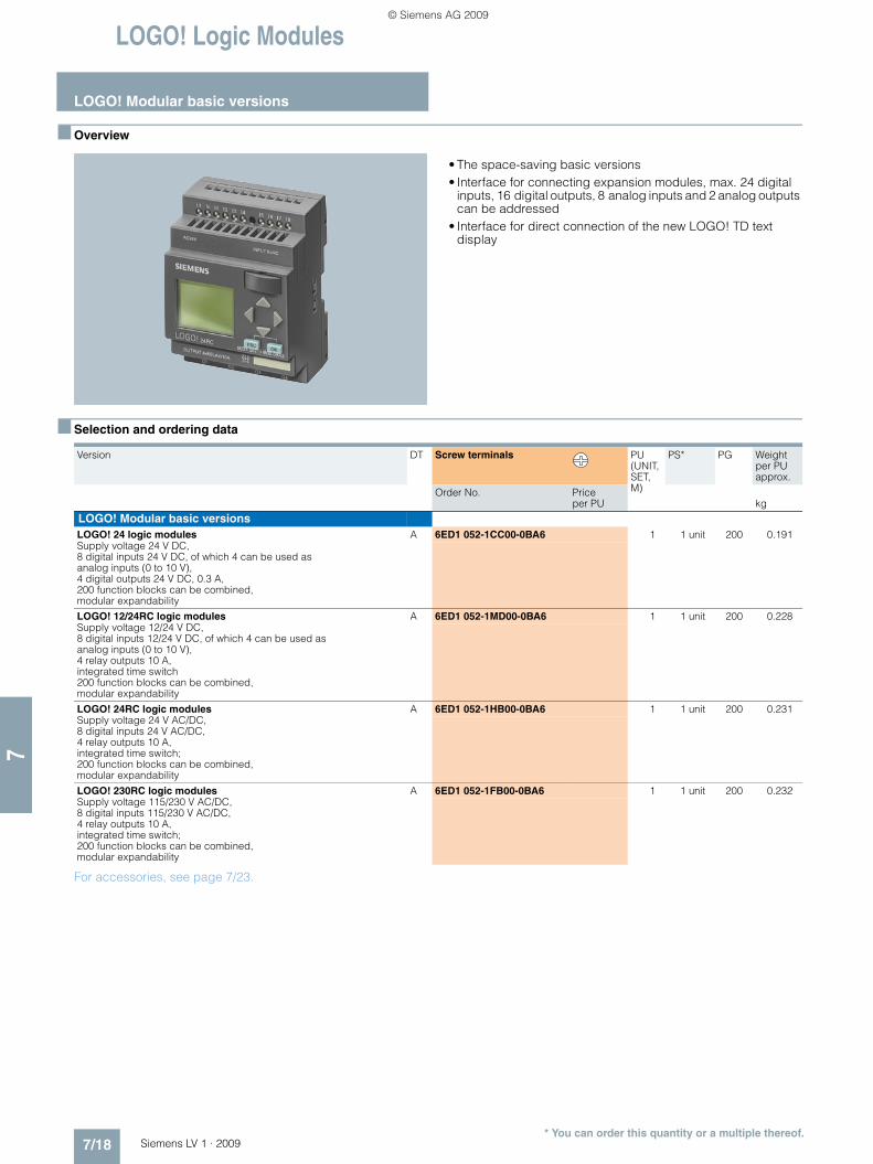
■ Overview
• The space-saving basic versions• Interface for connecting expansion modules, max. 24 digital
inputs, 16 digital outputs, 8 analog inputs and 2 analog outputs can be addressed
• Interface for direct connection of the new LOGO! TD text display
■ Selection and ordering data
For accessories, see page 7/23.
Version DT Screw terminals PU (UNIT, SET, M)
PS* PG Weight per PU approx.
Order No. Price per PU kg
LOGO! Modular basic versionsLOGO! 24 logic modules A 6ED1 052-1CC00-0BA6 1 1 unit 200 0.191Supply voltage 24 V DC, 8 digital inputs 24 V DC, of which 4 can be used as analog inputs (0 to 10 V), 4 digital outputs 24 V DC, 0.3 A, 200 function blocks can be combined,modular expandability
LOGO! 12/24RC logic modules A 6ED1 052-1MD00-0BA6 1 1 unit 200 0.228Supply voltage 12/24 V DC, 8 digital inputs 12/24 V DC, of which 4 can be used as analog inputs (0 to 10 V), 4 relay outputs 10 A, integrated time switch200 function blocks can be combined,modular expandability
LOGO! 24RC logic modules A 6ED1 052-1HB00-0BA6 1 1 unit 200 0.231Supply voltage 24 V AC/DC, 8 digital inputs 24 V AC/DC, 4 relay outputs 10 A, integrated time switch;200 function blocks can be combined,modular expandability
LOGO! 230RC logic modules A 6ED1 052-1FB00-0BA6 1 1 unit 200 0.232Supply voltage 115/230 V AC/DC, 8 digital inputs 115/230 V AC/DC, 4 relay outputs 10 A, integrated time switch;200 function blocks can be combined,modular expandability
* You can order this quantity or a multiple thereof.
LV1_09_Gesamt_EN.book Seite 18 Mittwoch, 11. Februar 2009 3:54 15
© Siemens AG 2009

LOGO! Logic Modules
LOGO! Modular pure versions
7/19Siemens LV 1 · 2009
77
■ Overview
• The cost-optimized basic versions• Interface for connecting expansion modules, max. 24 digital
inputs, 16 digital outputs, 8 analog inputs and 2 analog outputs can be addressed
• Interface for direct connection of the new LOGO! TD text display
■ Selection and ordering data
For accessories, see page 7/23.
Version DT Screw terminals PU (UNIT, SET, M)
PS* PG Weight per PU approx.
Order No. Price per PU kg
LOGO! Modular pure versionsLOGO! 24o logic modules A 6ED1 052-2CC00-0BA6 1 1 unit 200 0.175Supply voltage 24 V DC, 8 digital inputs 24 V DC, of which 4 can be used as analog inputs (0 to 10 V), 4 digital outputs 24 V DC, 0.3 A, without display and keyboard;200 function blocks can be combined,modular expandability
LOGO! 12/24RCo logic modules A 6ED1 052-2MD00-0BA6 1 1 unit 200 0.213Supply voltage 12/24 V DC, 8 digital inputs 12/24 V DC, of which 4 can be used as analog inputs (0 to 10 V), 4 relay outputs 10 A, integrated time switchwithout display and keyboard;200 function blocks can be combined,modular expandability
LOGO! 24RCo logic modules A 6ED1 052-2HB00-0BA6 1 1 unit 200 0.220Supply voltage 24 V AC/DC, 8 digital inputs 24 V AC/DC, 4 relay outputs 10 A, integrated time switch;without display and keyboard;200 function blocks can be combined,modular expandability
LOGO! 230RCo logic modules A 6ED1 052-2FB00-0BA6 1 1 unit 200 0.217Supply voltage 115/230 V AC/DC, 8 digital inputs 115/230 V AC/DC, 4 relay outputs 10 A, integrated time switch; without display and keyboard;200 function blocks can be combined,modular expandability
* You can order this quantity or a multiple thereof.
LV1_09_Gesamt_EN.book Seite 19 Mittwoch, 11. Februar 2009 3:54 15
© Siemens AG 2009

LOGO! Logic Modules
LOGO! Modular expansion modules
7/20 Siemens LV 1 · 2009
7
■ Overview
• Expansion modules for connection to LOGO! Modular• With digital inputs and outputs, analog inputs or analog outputs
■ Selection and ordering data
For accessories, see page 7/23.
Version DT Screw terminals PU (UNIT, SET, M)
PS* PG Weight per PU approx.
Order No. Price
per PU kg
LOGO! Modular expansion modulesLOGO! DM8 24 A 6ED1 055-1CB00-0BA0 1 1 unit 200 0.122Supply voltage 24 V DC, 4 digital inputs 24 V DC, 4 digital outputs 24 V DC, 0.3 A
LOGO! DM16 24 A 6ED1 055-1CB10-0BA0 1 1 unit 200 0.122Supply voltage 24 V DC, 8 digital inputs 24 V DC, 8 digital outputs 24 V DC, 0.3 A
LOGO! DM8 12/24R A 6ED1 055-1MB00-0BA1 1 1 unit 200 0.157Supply voltage 12/24 V DC, 4 digital inputs 12/24 V DC, 4 relay outputs 5 A
LOGO! DM8 24R A 6ED1 055-1HB00-0BA0 1 1 unit 200 0.158Supply voltage 24 V AC/DC, 4 digital inputs 24 V AC/DC, 4 relay outputs 5 A
LOGO! DM16 24R A 6ED1 055-1NB10-0BA0 1 1 unit 200 0.159Supply voltage 24 V DC, 8 digital inputs 24 V DC, 8 relay outputs 5 A
LOGO! DM8 230R A 6ED1 055-1FB00-0BA1 1 1 unit 200 0.159Supply voltage 115/230 V AC/DC, 4 digital inputs 115/230 V AC/DC, 4 relay outputs 5 A
LOGO! DM16 230R A 6ED1 055-1FB10-0BA0 1 1 unit 200 0.159Supply voltage 115/230 V AC/DC, 8 digital inputs 115/230 V AC/DC, 8 relay outputs 5 A
LOGO! AM2 A 6ED1 055-1MA00-0BA0 1 1 unit 200 0.119Supply voltage 12/24 V DC, 2 analog inputs 0 to 10 V or 0 to 20 mA, 10 bit resolution
LOGO! AM2 PT 100 A 6ED1 055-1MD00-0BA0 1 1 unit 200 0.120Supply voltage 12/24 V DC, 2 analog inputs Pt100, temperature range -50 °C to 200 °C
LOGO! AM2 AQ 6ED1 055-1MM00-0BA1Supply voltage 24 V DC, 2 analog outputs 0 to 10 V or 0/4 to 20 mA
* You can order this quantity or a multiple thereof.
LV1_09_Gesamt_EN.book Seite 20 Mittwoch, 11. Februar 2009 3:54 15
© Siemens AG 2009

LOGO! Logic Modules
LOGO! CM EIB/KNX communication modules
7/21Siemens LV 1 · 2009
77
■ Overview
• Expansion module for the LOGO! basic versions• For communication between LOGO! master and external EIB
components via EIB
■ Application
The CM EIB/KNX communication module allows communication between the LOGO! master and external EIB components via EIB. This module can be used to integrate LOGO! in an EIB system.
■ Selection and ordering data
For accessories, see page 7/23.
Version DT Screw terminals PU (UNIT, SET, M)
PS* PG Weight per PU approx.
Order No. Price per PU kg
LOGO! CM EIB/KNX communication modulesFor connection to EIB, supply voltage 24 V DC B 6BK1 700-0BA00-0AA1 1 1 unit 475 0.107
* You can order this quantity or a multiple thereof.
LV1_09_Gesamt_EN.book Seite 21 Mittwoch, 11. Februar 2009 3:54 15
© Siemens AG 2009

LOGO! Logic Modules
AS-Interface connections for LOGO!
7/22 Siemens LV 1 · 2009
7
■ Overview
Every LOGO! can now be connected to the AS-Interface system
Using the AS-Interface connection for LOGO!, an intelligent slave can be integrated in the AS-Interface system. With the modular interface it becomes possible to integrate the different basic units in the system according to their functionality. Simi-larly, functionalities can be quickly and easily adapted to new requirements by exchanging the basic unit.
The interface module provides four inputs and four outputs on the system. These I/Os do not actually exist in hardware terms, however, but are only virtually present through the interface on the bus.
■ Selection and ordering data
For accessories, see page 7/23.
Version DT Screw terminals PU (UNIT, SET, M)
PS* PG Weight per PU approx.
Order No. Price per PU kg
AS-Interface connections for LOGO!Four virtual inputs, four virtual outputs A 3RK1 400-0CE10-0AA2 1 1 unit 121 0.107
* You can order this quantity or a multiple thereof.
LV1_09_Gesamt_EN.book Seite 22 Mittwoch, 11. Februar 2009 3:54 15
© Siemens AG 2009

LOGO! Logic Modules
Accessories
7/23Siemens LV 1 · 2009
77
■ Selection and ordering data
Version DT Order No. Price per PU
PU (UNIT, SET, M)
PS* PG Weight per PU approx.
kg
LOGO! TD text displaysLOGO! TD text displays A 6ED1 055-4MH00-0BA0 1 1 unit 200 0.2704-line TD text display, for connection to all LOGO! Modular basic versions, degree of protection IP65, including connection cable
LOGO! manualsLOGO! manuals• German A 6ED1 050-1AA00-0AE7 1 1 unit 200 0.450• English A 6ED1 050-1AA00-0BE7 1 1 unit 200 0.401• French B 6ED1 050-1AA00-0CE7 1 1 unit 200 0.400• Spanish B 6ED1 050-1AA00-0DE7 1 1 unit 200 0.406• Italian B 6ED1 050-1AA00-0EE7 1 1 unit 200 0.402• Chinese B 6ED1 050-1AA00-0KE7 1 1 unit 200 0.402
LOGO! cardsLOGO! memory cards A 6ED1 056-1DA00-0BA0 1 1 unit 200 0.004For copying, with know-how protection
LOGO! battery cards A 6ED1 056-6XA00-0BA0 1 1 unit 200 0.004For adding a 2-year buffer to the integrated real-time clock
LOGO! memory/battery cards A 6ED1 056-7DA00-0BA0 1 1 unit 200 0.004Combination of memory and additional 2-year buffer for the integrated real-time clock
LOGO! cablesLOGO! PC cables A 6ED1 057-1AA00-0BA0 1 1 unit 200 0.176For transferring programs between LOGO! and PC
LOGO! USB PC cables A 6ED1 057-1AA01-0BA0 1 1 unit 200 0.160For transferring programs between LOGO! and PC,drivers on CD-Rom
LOGO! modem cables A 6ED1 057-1CA00-0BA0 1 1 unit 200 0.176Adapter cable for analog modem communication
Front panel assembly kitsFront panel assembly kits• Width: 4 MW C 6AG1 057-1AA00-0AA0 1 1 unit 470 0.150• Width: 4 MW, with pushbuttons D 6AG1 057-1AA00-0AA3 1 1 unit 470 0.150• Width: 8 MW C 6AG1 057-1AA00-0AA1 1 1 unit 470 0.170• Width: 8 MW, with pushbuttons D 6AG1 057-1AA00-0AA2 1 1 unit 470 0.170
LOGO! News BoxLOGO! News Box, 12/24 VContains LOGO! 12/24RC, LOGO! USB PC cable, LOGO! Soft Comfort V6.0, manual, screwdriver, information material• German A 6ED1 057-3BA00-0AA5 1 1 unit 2Z0 2.400• English A 6ED1 057-3BA00-0BA5 1 1 unit 2Z0 2.400
LOGO! News Box, 230 VContains LOGO! 230RC, LOGO! USB PC cable,LOGO! Soft Comfort V6.0,manual, screwdriver, information material• German A 6ED1 057-3AA02-0AA0 1 1 unit 2Z0 2.400• English A 6ED1 057-3AA02-0BA0 1 1 unit 2Z0 2.400
LOGO! TD News Box, 12/24 VContains LOGO! 12/24RCo, LOGO! TD, LOGO! USB PC cable,LOGO! Soft Comfort V6.0,manual, screwdriver, information material• German A 6ED1 057-3BA10-0AA0 1 1 unit 2Z0 2.700• English A 6ED1 057-3BA10-0BA0 1 1 unit 2Z0 2.700
* You can order this quantity or a multiple thereof.
LV1_09_Gesamt_EN.book Seite 23 Mittwoch, 11. Februar 2009 3:54 15
© Siemens AG 2009

LOGO! Logic Modules
LOGO! Contact
7/24 Siemens LV 1 · 2009
7
■ Overview
• Switching module for switching resistive loads and motors directly
■ Application
LOGO! Contact is a switching module for direct switching of resistive loads up (to 20 A) and motors (up to 4 kW). LOGO! Contact operates hum-free without noise pollution.
LOGO! Contact is universally applicable:• Buildings/electrical installations• Industry and commerce
■ Selection and ordering data
Version DT Screw terminals PU (UNIT, SET, M)
PS* PG Weight per PU approx.
Order No. Price per PU kg
LOGO! ContactSwitching module for direct switching of resistive loads up to 20 A and motors up to 4 kW• Switching voltage 24 V A 6ED1 057-4CA00-0AA0 1 1 unit 200 0.160• Switching voltage 230 V A 6ED1 057-4EA00-0AA0 1 1 unit 200 0.160
* You can order this quantity or a multiple thereof.
LV1_09_Gesamt_EN.book Seite 24 Mittwoch, 11. Februar 2009 3:54 15
© Siemens AG 2009
LOGO! Logic Modules
LOGO! Software
7/25Siemens LV 1 · 2009
77
■ Overview
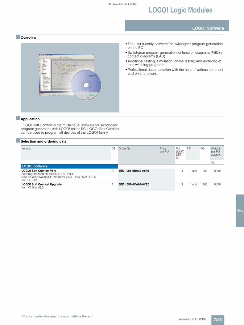
• The user-friendly software for switchgear program generation on the PC
• Switchgear program generation for function diagrams (FBD) or contact diagrams (LAD)
• Additional testing, simulation, online testing and archiving of the switching programs
• Professional documentation with the help of various comment and print functions
■ Application
LOGO! Soft Comfort is the multilingual software for switchgear program generation with LOGO! on the PC. LOGO! Soft Comfort can be used to program all devices of the LOGO! family.
■ Selection and ordering data
Version DT Order No. Price
per PUPU (UNIT, SET, M)
PS* PG Weight per PU approx.
kg
LOGO! SoftwareLOGO! Soft Comfort V6.0 A 6ED1 058-0BA02-0YA0 1 1 unit 200 0.001For programming on the PC in LAD/FBD; runs on Windows 98 SE, Windows Vista, Linux, MAC OS X; on CD-ROM
LOGO! Soft Comfort Upgrade A 6ED1 058-0CA02-0YE0 1 1 unit 200 0.001from V1.0 to V6.0
* You can order this quantity or a multiple thereof.
LV1_09_Gesamt_EN.book Seite 25 Mittwoch, 11. Februar 2009 3:54 15
© Siemens AG 2009

3RP, 3RT19 Timing Relays
3RP15 timing relaysin industrial enclosure, 22.5 mm
7/26 Siemens LV 1 · 2009
7
■ Overview
Standards
The timing relays comply with: • EN 60721-3-3 "Environmental conditions"• EN 61812-1
"Specified time relays for industrial use"• EN 61000-6-2 and EN 61000-6-4
"Electromagnetic compatibility"• EN 60947-5-1;
"Low-voltage switchgear and controlgear – Electromechanical control circuit devices"
Accessories
Push-in lugs for screw fixing
Sealable cover
Label set for marking the multifunction relay
■ Application
Timing relays are used in control, starting, and protective circuits for all switching operations involving time delays. They guaran-tee a high level of functionality and a high repeat accuracy of timer settings.
Enclosure version
All timing relays are suitable for snap-on mounting onto TH 35 standard mounting rails according to EN 60715 or for screw fixing.
���������� ���������� �������� ���
���������� ������ �������������������� ����������������
����������
������� ������ ��
���� ������ � ������
!������������������������ ��
!������������������������
LV1_09_Gesamt_EN.book Seite 26 Mittwoch, 11. Februar 2009 3:54 15
© Siemens AG 2009

3RP, 3RT19 Timing Relays
3RP15 timing relaysin industrial enclosure, 22.5 mm
7/27Siemens LV 1 · 2009
77
■ Selection and ordering data
Solid-state timing relays for general use in control systems and mechanical engineering with:• 1 changeover contact or 2 changeover contacts
• Single or selectable time setting ranges• Switch position indication by LED• Voltage indication by LED
1) With switch position ∞, no timing. For test purposes (ON/OFF function) on site. Relay is constantly on when activated, or relay remains constantly off when activated. Depending on which function is set.
2) Operating range 0.7 to 1.1 x Us.3) Positively driven: NO and NC are never closed simultaneously; contact
gap ≥ 0.5 mm is ensured, minimum make-break capacity 12 V, 3 mA.
4) The changeover contacts are actuated simultaneously, as a result of which only 8 functions are selectable (no wye-delta, no instantaneous contact).
5) Operating range 0.8 to 1.1 x Us.
Version Time setting range tadjustable by rotary switch to
Rated control supply voltage Us
DT Screw terminals PU (UNIT, SET, M)
PS* PG Weight per PU approx.
AC 50/60 Hz DC Order No. Price per PU
V V kg3RP15 05 timing relays, multifunction, 15 time setting ranges
3RP15 05-1BP30
The functions can be adjusted by means of rotary switches. Insert labels can be used to adjust different functions of the 3RP15 05 timing relay clearly and unmistakably. The corresponding labels can be ordered as an accessory. The same potential must be applied to terminals A. and B. For functions see 3RP19 01 label set, page 7/31.
With LED and
1 CO contact, 8 functions
0.05 ... 1 s0.15 ... 3 s0.5 ... 10 s1.5 ... 30 s0.05 ... 1 min 5 ... 100 s0.15 ... 3 min 0.5 ... 10 min 1.5 ... 30 min 0.05 ... 1 h 5 ... 100 min 0.15 ... 3 h 0.5 ... 10 h 1.5 ... 30 h 5 ... 100 h ∞ 1)
-- 12 A 3RP15 05-1AA40 1 1 unit 101 0.12524/100 ... 127 24 } 3RP15 05-1AQ30 1 1 unit 101 0.14024/200 ... 240 24 } 3RP15 05-1AP30 1 1 unit 101 0.14124 ... 2405) 24 ... 2402) } 3RP15 05-1AW30 1 1 unit 101 0.136
2 CO contacts, 16 functions
24/100 ... 127 24 } 3RP15 05-1BQ30 1 1 unit 101 0.16224/200 ... 240 24 } 3RP15 05-1BP30 1 1 unit 101 0.16124 ... 2405) 24 ... 2402) } 3RP15 05-1BW30 1 1 unit 101 0.168400 ... 440 - A 3RP15 05-1BT20 1 1 unit 101 0.169
2 CO contacts, positively driven and hard gold-plated. 8 functions3)4)
24 ... 240 24 ... 240 } 3RP15 05-1RW30 1 1 unit 101 0.169
3RP15 1. timing relays, ON-delay, 1 time setting range
3RP15 11-1AP30
With LED and1 CO contact
0.5 ... 10 s 24/100 ... 127 24 } 3RP15 11-1AQ30 1 1 unit 101 0.10824/200 ... 240 24 } 3RP15 11-1AP30 1 1 unit 101 0.108
1.5 ... 30 s 24/100 ... 127 24 } 3RP15 12-1AQ30 1 1 unit 101 0.10724/200 ... 240 24 } 3RP15 12-1AP30 1 1 unit 101 0.104
5 ... 100 s 24/100 ... 127 24 } 3RP15 13-1AQ30 1 1 unit 101 0.10724/200 ... 240 24 } 3RP15 13-1AP30 1 1 unit 101 0.108
3RP15 25 timing relays, ON-delay, 15 time setting ranges
3RP15 25-1BW30
With LED and
1 CO contact 0.05 ... 1 s0.15 ... 3 s0.5 ... 10 s1.5 ... 30 s0.05 ... 1 min 5 ... 100 s0.15 ... 3 min 0.5 ... 10 min 1.5 ... 30 min 0.05 ... 1 h 5 ... 100 min 0.15 ... 3 h 0.5 ... 10 h 1.5 ... 30 h 5 ... 100 h ∞ 1)
24/100 ... 127 24 } 3RP15 25-1AQ30 1 1 unit 101 0.10924/200 ... 240 24 } 3RP15 25-1AP30 1 1 unit 101 0.104
2 CO contacts 42 ... 48/60 42 ... 48/ 605)
A 3RP15 25-1BR30 1 1 unit 101 0.152
24/100 ... 127 24 } 3RP15 25-1BQ30 1 1 unit 101 0.15224/200 ... 240 24 } 3RP15 25-1BP30 1 1 unit 101 0.15524 ... 2405) 24 ... 2402) } 3RP15 25-1BW30 1 1 unit 101 0.159
3RP15 27 timing relays, ON-delay, two-wire design, 4 time setting ranges
3RP15 27-1EM30
1 NO contact (semiconductor)
0.05 ... 1 s0.2 ... 4 s1.5 ... 30 s12 ... 240 s
24 ... 66 24...665) A 3RP15 27-1EC30 1 1 unit 101 0.09990 ... 240 90...2405) } 3RP15 27-1EM30 1 1 unit 101 0.100
* You can order this quantity or a multiple thereof.
LV1_09_Gesamt_EN.book Seite 27 Mittwoch, 11. Februar 2009 3:54 15
© Siemens AG 2009

3RP, 3RT19 Timing Relays
3RP15 timing relaysin industrial enclosure, 22.5 mm
7/28 Siemens LV 1 · 2009
7
Solid-state timing relays for general use in control systems and mechanical engineering with• 1 changeover contact or 2 changeover contacts
• Single or selectable time setting ranges• Switch position indication by LED• Voltage indication by LED
1) With switch position ∞, no timing. For test purposes (ON/OFF function) on site. Relay is constantly on when activated, or relay remains constantly off when activated. Depending on which function is set.
2) Operating range 0.7 to 1.1 x Us.3) Positively driven: NO and NC are never closed simultaneously; contact
gap ≥ 0.5 mm is ensured, minimum make-break capacity 12 V, 3 mA.
4) The changeover contacts are actuated simultaneously, as a result of which only 8 functions are selectable (no wye-delta, no instantaneous contact).
5) Operating range 0.8 to 1.1 x Us.
Version Time setting range tadjustable by rotary switch to
Rated control supply voltage Us
DT Spring-type terminals
PU (UNIT, SET, M)
PS* PG Weight per PU approx.
AC 50/60 Hz DC Order No. Price per PU
V V kg3RP15 05 timing relays, multifunction, 15 time setting ranges
3RP15 05-2BP30
The functions can be adjusted by means of rotary switches. Insert labels can be used to adjust different functions of the 3RP15 05 timing relay clearly and unmistakably. The corresponding labels can be ordered as an accessory. The same potential must be applied to terminals A. and B. For functions see 3RP19 01 label set, page 7/31.
With LED and
1 CO contact, 8 functions
0.05 ... 1 s0.15 ... 3 s0.5 ... 10 s1.5 ... 30 s0.05 ... 1 min 5 ... 100 s0.15 ... 3 min 0.5 ... 10 min 1.5 ... 30 min 0.05 ... 1 h 5 ... 100 min 0.15 ... 3 h 0.5 ... 10 h 1.5 ... 30 h 5 ... 100 h ∞ 1)
24/100 ... 127 24 C 3RP15 05-2AQ30 1 1 unit 101 0.12524/200 ... 240 24 A 3RP15 05-2AP30 1 1 unit 101 0.12624 ... 2405) 24 ... 2402) A 3RP15 05-2AW30 1 1 unit 101 0.132
2 CO contacts, 16 functions
24/100 ... 127 24 A 3RP15 05-2BQ30 1 1 unit 101 0.14224/200 ... 240 24 A 3RP15 05-2BP30 1 1 unit 101 0.13724 ... 2405) 24 ... 2402) A 3RP15 05-2BW30 1 1 unit 101 0.143
2 CO contacts, positively driven and hard gold-plated. 8 functions3)4)
24 ... 240 24 ... 240 A 3RP15 05-2RW30 1 1 unit 101 0.143
3RP15 1. timing relays, ON-delay, 1 time setting range
3RP15 11-2AP30
With LED and 1 CO contact
0.5 ... 10 s 24/100 ... 127 24 C 3RP15 11-2AQ30 1 1 unit 101 0.09224/200 ... 240 24 A 3RP15 11-2AP30 1 1 unit 101 0.092
1.5 ... 30 s 24/100 ... 127 24 C 3RP15 12-2AQ30 1 1 unit 101 0.09224/200 ... 240 24 A 3RP15 12-2AP30 1 1 unit 101 0.097
5 ... 100 s 24/100 ... 127 24 C 3RP15 13-2AQ30 1 1 unit 101 0.09424/200 ... 240 24 A 3RP15 13-2AP30 1 1 unit 101 0.094
3RP15 25 timing relays, ON-delay, 15 time setting ranges
3RP15 25-2BW30
With LED and
1 CO contact 0.05 ... 1 s0.15 ... 3 s0.5 ... 10 s1.5 ... 30 s0.05 ... 1 min 5 ... 100 s0.15 ... 3 min 0.5 ... 10 min 1.5 ... 30 min 0.05 ... 1 h 5 ... 100 min 0.15 ... 3 h 0.5 ... 10 h 1.5 ... 30 h 5 ... 100 h ∞ 1)
24/100 ... 127 24 C 3RP15 25-2AQ30 1 1 unit 101 0.09524/200 ... 240 24 A 3RP15 25-2AP30 1 1 unit 101 0.093
2 CO contacts 24/100 ... 127 24 C 3RP15 25-2BQ30 1 1 unit 101 0.12824/200 ... 240 24 A 3RP15 25-2BP30 1 1 unit 101 0.12724 ... 2405) 24 ... 2402) A 3RP15 25-2BW30 1 1 unit 101 0.134
3RP15 27 timing relays, ON-delay, two-wire design, 4 time setting ranges
3RP15 27-2EM30
1 NO contact (semiconductor)
0.05 ... 1 s0.2 ... 4 s1.5 ... 30 s12 ... 240 s
24 ... 66 24...665) C 3RP15 27-2EC30 1 1 unit 101 0.09090 ... 240 90...2405) C 3RP15 27-2EM30 1 1 unit 101 0.090
* You can order this quantity or a multiple thereof.
LV1_09_Gesamt_EN.book Seite 28 Mittwoch, 11. Februar 2009 3:54 15
© Siemens AG 2009

3RP, 3RT19 Timing Relays
3RP15 timing relaysin industrial enclosure, 22.5 mm
7/29Siemens LV 1 · 2009
77
Solid-state timing relays for general use in control systems and mechanical engineering with • 1 changeover contact or 2 changeover contacts
• Single or selectable time setting ranges• Switch position indication by LED• Voltage indication by LED
1) Setting of output contacts in as-supplied state not defined (bistable relay). Application of the control voltage once results in contact changeover to the correct setting.
2) Operating range 0.7 to 1.25 x Us.3) Operating range 0.85 to 1.1 x Us.
4) With switch position ∞, no timing. For test purposes (ON/OFF function) on site. For dead time "infinite", the relay is always off. For pulse time "infinite", the relay is always on.
5) Operating range 0.8 to 1.1 x Us.6) For example circuit see Technical Information LV 1 T, "Schematics".
Version Time setting range tadjustable by rotary switch to
Rated control supply voltage Us DT Screw terminals PU (UNIT, SET, M)
PS* PG Weight per PU approx.
AC 50/60 Hz DC Order No. Price per PU
V V kg3RP15 3. timing relays, OFF-delay, with auxiliary voltage, 1 time setting range
3RP15 33-1AP30
With LED and1 CO contactThe same potential must be applied to terminals A and B
0.5 ... 10 s 24/100 ... 127 24 A 3RP15 31-1AQ30 1 1 unit 101 0.14024/200 ... 240 24 } 3RP15 31-1AP30 1 1 unit 101 0.140
1.5 ... 30 s 24/100 ... 127 24 A 3RP15 32-1AQ30 1 1 unit 101 0.13824/200 ... 240 24 } 3RP15 32-1AP30 1 1 unit 101 0.139
5 ... 100 s 24/100 ... 127 24 A 3RP15 33-1AQ30 1 1 unit 101 0.13924/200 ... 240 24 } 3RP15 33-1AP30 1 1 unit 101 0.140
3RP15 40 timing relays, OFF-delay, without auxiliary voltage, 9 time setting ranges1)
3RP15 40-1BB31
With LED and
1 CO contact 0.05 ... 1 s0.15 ... 3 s0.3 ... 6 s0.5 ... 10 s1.5 ... 30 s3 ... 60 s5 ... 100 s15 ... 300 s30 ... 600 s
24 242) } 3RP15 40-1AB31 1 1 unit 101 0.116100 ... 127 100...1273) } 3RP15 40-1AJ31 1 1 unit 101 0.119200 ... 240 200...2403) } 3RP15 40-1AN31 1 1 unit 101 0.12024 ... 240 24 ... 2403) } 3RP15 40-1AW31 1 1 unit 101 0.116
2 CO contacts 24 242) } 3RP15 40-1BB31 1 1 unit 101 0.159100 ... 127 100...1273) A 3RP15 40-1BJ31 1 1 unit 101 0.161200 ... 240 200...2403) } 3RP15 40-1BN31 1 1 unit 101 0.16124 ... 240 24 ... 2403) } 3RP15 40-1BW31 1 1 unit 101 0.159
3RP15 55 timing relays, clock-pulse relay, 15 time setting ranges
3RP15 55-1AP30
With LED and1 CO contact
0.05 ... 1 s0.15 ... 3 s0.5 ... 10 s1.5 ... 30 s0.05 ... 1 min 5 ... 100 s0.15 ... 3 min 0.5 ... 10 min 1.5 ... 30 min 0.05 ... 1 h 5 ... 100 min 0.15 ... 3 h 0.5 ... 10 h 1.5 ... 30 h 5 ... 100 h ∞ 4)
42 ... 48/60 42...48/ 605) A 3RP15 55-1AR30 1 1 unit 101 0.11124/100 ... 127 24 } 3RP15 55-1AQ30 1 1 unit 101 0.11124/200 ... 240 24 } 3RP15 55-1AP30 1 1 unit 101 0.111
3RP15 60 timing relays, wye-delta function, dead interval 50 ms and overtravel time, 1 time setting range
3RP15 60-1SP30
3 NO contacts3) (common contact root terminal 17)
Wye-delta 1 ... 20 s, overtravel time (idling) 30 ... 600 s
24/100 ... 127 24 A 3RP15 60-1SQ30 1 1 unit 101 0.17224/200 ... 240 24 } 3RP15 60-1SP30 1 1 unit 101 0.175
3RP15 7. timing relays, wye-delta function6), dead interval 50 ms, 1 time setting range
3RP15 76-1NP30
1 NO contact instantaneous and 1 NO contact delayed (common contact root terminal 17)
1 ... 20 s 24/100 ... 127 24 } 3RP15 74-1NQ30 1 1 unit 101 0.11324/200 ... 240 24 } 3RP15 74-1NP30 1 1 unit 101 0.113200 ... 240/380 ...440
-- B 3RP15 74-1NM20 1 1 unit 101 0.113
3 ... 60 s 24/100 ... 127 24 } 3RP15 76-1NQ30 1 1 unit 101 0.11224/200 ... 240 24 } 3RP15 76-1NP30 1 1 unit 101 0.113200 ... 240/380 ...440
-- B 3RP15 76-1NM20 1 1 unit 101 0.113
* You can order this quantity or a multiple thereof.
LV1_09_Gesamt_EN.book Seite 29 Mittwoch, 11. Februar 2009 3:54 15
© Siemens AG 2009

3RP, 3RT19 Timing Relays
3RP15 timing relaysin industrial enclosure, 22.5 mm
7/30 Siemens LV 1 · 2009
7
Solid-state timing relays for general use in control systems and mechanical engineering with • 1 changeover contact or 2 changeover contacts
• Single or selectable time setting ranges• Switch position indication by LED• Voltage indication by LED
1) Setting of output contacts in as-supplied state not defined (bistable relay). Application of the control voltage once results in contact changeover to the correct setting.
2) Operating range 0.7 to 1.25 x Us.3) Operating range 0.85 to 1.1 x Us.
4) With switch position ∞, no timing. For test purposes (ON/OFF function) on site. For dead time "infinite", the relay is always off. For pulse time "infinite", the relay is always on.
5) Operating range 0.8 to 1.1 x Us.6) For example circuit, see Technical Information LV 1 T, "Schematics".
Version Time setting range t adjustable by rotary switch to
Rated control supply voltage Us DT Spring-type terminals
PU (UNIT, SET, M)
PS* PG Weight per PU approx.
AC 50/60 Hz DC Order No. Price per PU
V V kg3RP15 3. timing relays, OFF-delay, with auxiliary voltage, 1 time setting range
3RP15 33-2AP30
With LED and1 CO contactThe same potential must be applied to terminals A and B
0.5 ... 10 s 24/100 ... 127 24 C 3RP15 31-2AQ30 1 1 unit 101 0.12424/200 ... 240 24 C 3RP15 31-2AP30 1 1 unit 101 0.122
1.5 ... 30 s 24/100 ... 127 24 C 3RP15 32-2AQ30 1 1 unit 101 0.12524/200 ... 240 24 A 3RP15 32-2AP30 1 1 unit 101 0.121
5 ... 100 s 24/100 ... 127 24 C 3RP15 33-2AQ30 1 1 unit 101 0.12324/200 ... 240 24 C 3RP15 33-2AP30 1 1 unit 101 0.125
3RP15 40 timing relays, OFF-delay, without auxiliary voltage, 9 time setting ranges1)
3RP15 40-2BB31
With LED and
1 CO contact 0.05 ... 1 s0.15 ... 3 s0.3 ... 6 s0.5 ... 10 s1.5 ... 30 s3 ... 60 s5 ... 100 s15 ... 300 s30 ... 600 s
24 242) A 3RP15 40-2AB31 1 1 unit 101 0.105100 ... 127 100...1273) A 3RP15 40-2AJ31 1 1 unit 101 0.108200 ... 240 200...2403) A 3RP15 40-2AN31 1 1 unit 101 0.11024 ... 240 24...2403) A 3RP15 40-2AW31 1 1 unit 101 0.105
2 CO contacts 24 242) A 3RP15 40-2BB31 1 1 unit 101 0.136100 ... 127 100...1273) A 3RP15 40-2BJ31 1 1 unit 101 0.136200 ... 240 200...2403) C 3RP15 40-2BN31 1 1 unit 101 0.13624 ... 240 24...2403) A 3RP15 40-2BW31 1 1 unit 101 0.136
3RP15 55 timing relays, clock-pulse relay, 15 time setting ranges
3RP15 55-2AP30
With LED and 1 changeover contact
0.05 ... 1 s0.15 ... 3 s0.5 ... 10 s1.5 ... 30 s0.05 ... 1 min 5 ... 100 s0.15 ... 3 min 0.5 ... 10 min 1.5 ... 30 min 0.05 ... 1 h 5 ... 100 min 0.15 ... 3 h 0.5 ... 10 h 1.5 ... 30 h 5 ... 100 h ∞ 4)
42 ... 48/60 42...48/605) C 3RP15 55-2AR30 1 1 unit 101 0.10224/100 ... 127 24 C 3RP15 55-2AQ30 1 1 unit 101 0.10024/200 ... 240 24 A 3RP15 55-2AP30 1 1 unit 101 0.104
3RP15 60 timing relays, wye-delta function, dead interval 50 ms and overtravel time, 1 time setting range
3RP15 60-2SP30
3 NO contacts3) (common contact root terminal 17)
Wye-delta 1 ... 20 s, overtravel time (idling) 30 ... 600 s
24/200 ... 240 24 C 3RP15 60-2SP30 1 1 unit 101 0.152
3RP15 7. timing relays, wye-delta function6), dead interval 50 ms, 1 time setting range
1 NO contact instantaneous and 1 NO contact delayed (common contact root terminal 17)
1 ... 20 s 24/200 ... 240 24 A 3RP15 74-2NP30 1 1 unit 101 0.104200 ... 240/380 ...440
B 3RP15 74-2NM20 1 1 unit 101 0.100
3 ... 60 s 24/100 ... 127 24 A 3RP15 76-2NQ30 1 1 unit 101 0.10224/200 ... 240 24 A 3RP15 76-2NP30 1 1 unit 101 0.104200 ... 240/ 380 ... 440
B 3RP15 76-2NM20 1 1 unit 101 0.100
* You can order this quantity or a multiple thereof.
LV1_09_Gesamt_EN.book Seite 30 Mittwoch, 11. Februar 2009 3:54 15
© Siemens AG 2009

3RP, 3RT19 Timing Relays
3RP15 timing relaysin industrial enclosure, 22.5 mm
7/31Siemens LV 1 · 2009
77
■ Accessories
1) Computer labeling system for individual inscription of unit labeling plates available from: murrplastik Systemtechnik GmbH. http://www.murrplastik.com
Version Function Iden-tifica-tion letter
Use DT Order No. Price per PU
PU (UNIT, SET, M)
PS* PG Weight per PU approx.
kgLabel sets
Accessory for 3RP15 05 (not included in the scope of supply). The label set offers the possibility of labeling timing relays with the set function in English and German.
3RP19 01-0A
1 label set (1 unit) with 8 functions
With ON-delay A for devices with 1 CO contact and 3RP15 05-.RW30
} 3RP19 01-0A 1 5 units 101 0.003
OFF-delay with auxiliary voltage B
ON-delay and OFF-delay with aux-iliary voltage
C
Flashing, starting with interval D
Passing make contact E
Passing break contact with auxil-iary voltage
F
Pulse-forming with auxiliary voltage G
Additive ON-delay with auxiliary voltage
H
3RP19 01-0B
1 label set (1 unit) with 16 functions
With ON-delay A for devices with 2 CO contacts
} 3RP19 01-0B 1 5 units 101 0.006
OFF-delay with auxiliary voltage B
ON-delay and OFF-delay with aux-iliary voltage
C
Flashing, starting with interval D
Passing make contact E
Passing break contact with auxil-iary voltage
F
Pulse-forming with auxiliary voltage G
Additive ON-delay with auxiliary voltage and instantaneous contact
H•
ON-delay and instantaneous con-tact
A•
OFF-delay with auxiliary voltage and instantaneous contact
B•
ON-delay and OFF-delay with aux-iliary voltage and instantaneous contact
C•
Flashing, starting with interval, and instantaneous contact
D•
Passing make contact and instan-taneous contact
E•
Passing break contact with auxil-iary voltage and instantaneous contact
F•
Pulse-forming with auxiliary voltage and instantaneous contact
G•
Wye-delta function *ΔBlank labels
Blank labels, 20 mm x 7 mm, pastel turquoise1) C 3RT19 00-1SB20 100 340 units 101 0.200
Covers and push-in lugs
3RP19 03
Push-in lugs For screw fixing,2 units are required for each device
} 3RP19 03 1 10 units 101 0.002
3RP19 02
Sealable covers For securing against unauthorized adjustment of setting knobs
} 3RP19 02 1 5 units 101 0.004
* You can order this quantity or a multiple thereof.
LV1_09_Gesamt_EN.book Seite 31 Mittwoch, 11. Februar 2009 3:54 15
© Siemens AG 2009
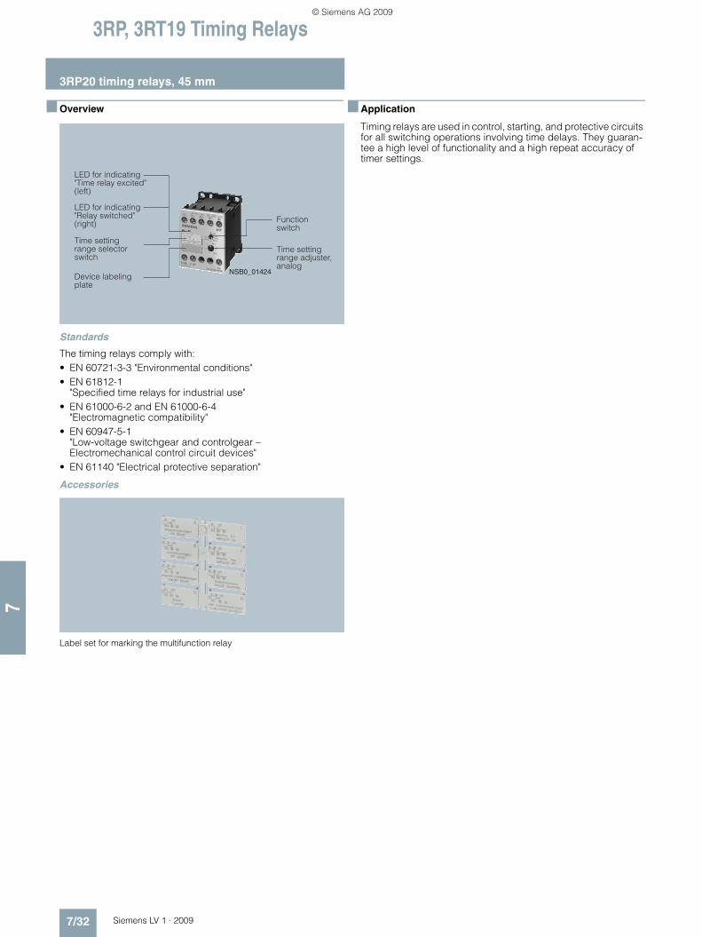
3RP, 3RT19 Timing Relays
3RP20 timing relays, 45 mm
7/32 Siemens LV 1 · 2009
7
■ Overview
Standards
The timing relays comply with: • EN 60721-3-3 "Environmental conditions"• EN 61812-1
"Specified time relays for industrial use"• EN 61000-6-2 and EN 61000-6-4
"Electromagnetic compatibility"• EN 60947-5-1
"Low-voltage switchgear and controlgear – Electromechanical control circuit devices"
• EN 61140 "Electrical protective separation"
Accessories
Label set for marking the multifunction relay
■ Application
Timing relays are used in control, starting, and protective circuits for all switching operations involving time delays. They guaran-tee a high level of functionality and a high repeat accuracy of timer settings.
���������� ���������� ���"�����#����$
���������� ������ ����������#����$
���������� ����������������
������� ������ ��
����������
���������� ��� � �����% ���
*�8%.%�&�&
LV1_09_Gesamt_EN.book Seite 32 Mittwoch, 11. Februar 2009 3:54 15
© Siemens AG 2009
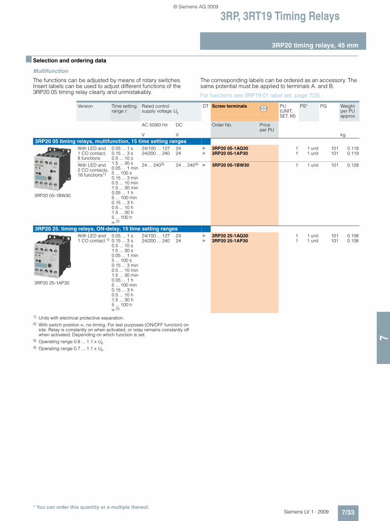
3RP, 3RT19 Timing Relays
3RP20 timing relays, 45 mm
7/33Siemens LV 1 · 2009
77
■ Selection and ordering data
Multifunction
The functions can be adjusted by means of rotary switches.Insert labels can be used to adjust different functions of the 3RP20 05 timing relay clearly and unmistakably.
The corresponding labels can be ordered as an accessory. The same potential must be applied to terminals A. and B.
For functions see 3RP19 01 label set, page 7/35.
1) Units with electrical protective separation.2) With switch position ∞, no timing. For test purposes (ON/OFF function) on
site. Relay is constantly on when activated, or relay remains constantly off when activated. Depending on which function is set.
3) Operating range 0.8 ... 1.1 x Us.4) Operating range 0.7 ... 1.1 x Us.
Version Time setting range t
Rated control supply voltage Us
DT Screw terminals PU (UNIT, SET, M)
PS* PG Weight per PU approx.
AC 50/60 Hz DC Order No. Price per PU
V V kg3RP20 05 timing relays, multifunction, 15 time setting ranges
3RP20 05-1BW30
With LED and 1 CO contact, 8 functions
0.05 ... 1 s0.15 ... 3 s0.5 ... 10 s1.5 ... 30 s0.05 ... 1 min 5 ... 100 s0.15 ... 3 min 0.5 ... 10 min 1.5 ... 30 min 0.05 ... 1 h 5 ... 100 min 0.15 ... 3 h 0.5 ... 10 h 1.5 ... 30 h 5 ... 100 h ∞ 2)
24/100 ... 127 24 } 3RP20 05-1AQ30 1 1 unit 101 0.11824/200 ... 240 24 } 3RP20 05-1AP30 1 1 unit 101 0.119
With LED and 2 CO contacts, 16 functions1)
24 ... 2403) 24 ... 2404) } 3RP20 05-1BW30 1 1 unit 101 0.128
3RP20 25. timing relays, ON-delay, 15 time setting ranges
3RP20 25-1AP30
With LED and 1 CO contact 1)
0.05 ... 1 s0.15 ... 3 s0.5 ... 10 s1.5 ... 30 s0.05 ... 1 min 5 ... 100 s0.15 ... 3 min 0.5 ... 10 min 1.5 ... 30 min 0.05 ... 1 h 5 ... 100 min 0.15 ... 3 h 0.5 ... 10 h 1.5 ... 30 h 5 ... 100 h ∞ 2)
24/100 ... 127 24 } 3RP20 25-1AQ30 1 1 unit 101 0.10624/200 ... 240 24 } 3RP20 25-1AP30 1 1 unit 101 0.106
* You can order this quantity or a multiple thereof.
LV1_09_Gesamt_EN.book Seite 33 Mittwoch, 11. Februar 2009 3:54 15
© Siemens AG 2009

3RP, 3RT19 Timing Relays
3RP20 timing relays, 45 mm
7/34 Siemens LV 1 · 2009
7
Multifunction
The functions can be adjusted by means of rotary switches.Insert labels can be used to adjust different functions of the 3RP20 05 timing relay clearly and unmistakably.
The corresponding labels can be ordered as an accessory. The same potential must be applied to terminals A. and B.
For functions see 3RP19 01 label set, page 7/35.
1) Units with electrical protective separation.2) With switch position ∞, no timing. For test purposes (ON/OFF function) on
site. Relay is constantly on when activated, or relay remains constantly off when activated. Depending on which function is set.
3) Operating range 0.8 to 1.1 x Us.4) Operating range 0.7 to 1.1 x Us.
Version Time setting range t
Rated control supply voltage Us
DT Spring-typeterminals
PU (UNIT, SET, M)
PS* PG Weight per PU approx.
AC 50/60 Hz DC Order No. Price per PU
V V kg3RP20 05 timing relays, multifunction, 15 time setting ranges
3RP20 05-2BW30
With LED and 1 CO contact, 8 functions1)
0.05 ... 1 s0.15 ... 3 s0.5 ... 10 s1.5 ... 30 s0.05 ... 1 min 5 ... 100 s0.15 ... 3 min 0.5 ... 10 min 1.5 ... 30 min 0.05 ... 1 h 5 ... 100 min 0.15 ... 3 h 0.5 ... 10 h 1.5 ... 30 h 5 ... 100 h ∞ 2)
24/ 100 ... 127 24 D 3RP20 05-2AQ30 1 1 unit 101 0.12024/ 200 ... 240 24 } 3RP20 05-2AP30 1 1 unit 101 0.121
With LED and 2 CO contact, 16 functions
24 ... 2403) 24 ... 2404) D 3RP20 05-2BW30 1 1 unit 101 0.131
3RP20 25. timing relays, ON-delay, 15 time setting ranges
3RP20 25-2AP30
With LED and 1 CO contact 1)
0.05 ... 1 s0.15 ... 3 s0.5 ... 10 s1.5 ... 30 s0.05 ... 1 min 5 ... 100 s0.15 ... 3 min 0.5 ... 10 min 1.5 ... 30 min 0.05 ... 1 h 5 ... 100 min 0.15 ... 3 h 0.5 ... 10 h 1.5 ... 30 h 5 ... 100 h ∞ 2)
24/ 100 ... 127 24 } 3RP20 25-2AQ30 1 1 unit 101 0.11024/ 200 ... 240 24 } 3RP20 25-2AP30 1 1 unit 101 0.108
* You can order this quantity or a multiple thereof.
LV1_09_Gesamt_EN.book Seite 34 Mittwoch, 11. Februar 2009 3:54 15
© Siemens AG 2009
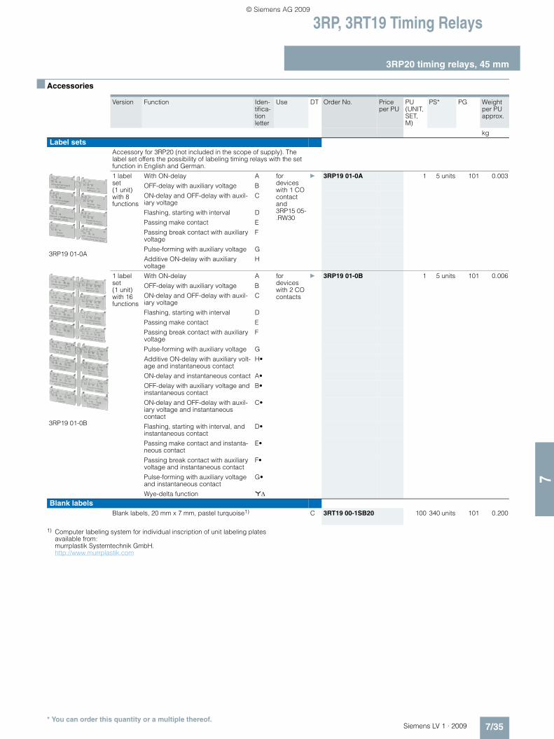
3RP, 3RT19 Timing Relays
3RP20 timing relays, 45 mm
7/35Siemens LV 1 · 2009
77
■ Accessories
1) Computer labeling system for individual inscription of unit labeling plates available from: murrplastik Systemtechnik GmbH. http://www.murrplastik.com
Version Function Iden-tifica-tion letter
Use DT Order No. Price per PU
PU (UNIT, SET, M)
PS* PG Weight per PU approx.
kgLabel sets
Accessory for 3RP20 (not included in the scope of supply). The label set offers the possibility of labeling timing relays with the set function in English and German.
3RP19 01-0A
1 label set (1 unit) with 8 functions
With ON-delay A for devices with 1 CO contact and 3RP15 05-.RW30
} 3RP19 01-0A 1 5 units 101 0.003
OFF-delay with auxiliary voltage B
ON-delay and OFF-delay with auxil-iary voltage
C
Flashing, starting with interval D
Passing make contact E
Passing break contact with auxiliary voltage
F
Pulse-forming with auxiliary voltage G
Additive ON-delay with auxiliary voltage
H
3RP19 01-0B
1 label set (1 unit) with 16 functions
With ON-delay A for devices with 2 CO contacts
} 3RP19 01-0B 1 5 units 101 0.006
OFF-delay with auxiliary voltage B
ON-delay and OFF-delay with auxil-iary voltage
C
Flashing, starting with interval D
Passing make contact E
Passing break contact with auxiliary voltage
F
Pulse-forming with auxiliary voltage G
Additive ON-delay with auxiliary volt-age and instantaneous contact
H•
ON-delay and instantaneous contact A•
OFF-delay with auxiliary voltage and instantaneous contact
B•
ON-delay and OFF-delay with auxil-iary voltage and instantaneous contact
C•
Flashing, starting with interval, and instantaneous contact
D•
Passing make contact and instanta-neous contact
E•
Passing break contact with auxiliary voltage and instantaneous contact
F•
Pulse-forming with auxiliary voltage and instantaneous contact
G•
Wye-delta function *ΔBlank labels
Blank labels, 20 mm x 7 mm, pastel turquoise1) C 3RT19 00-1SB20 100 340 units 101 0.200
* You can order this quantity or a multiple thereof.
LV1_09_Gesamt_EN.book Seite 35 Mittwoch, 11. Februar 2009 3:54 15
© Siemens AG 2009

3RP, 3RT19 Timing Relays
3RT19 16, 3RT19 26 timing relaysfor mounting onto contactors
7/36 Siemens LV 1 · 2009
7
■ Selection and ordering data
1) The terminals for the rated control supply voltage are connected to the contactor beneath by the integrated spring-type contacts of the solid-state time-delay auxiliary switch block when mounting.
2) Setting of output contacts in as-supplied state not defined (bistable relay). Application of the control voltage once results in contact changeover to the correct setting.
3) The terminals A1 and A2 for the rated control supply voltage of the solid-state time-delay auxiliary switch block must be connected to the corre-sponding contactor by connecting cables.
For con-tactors
Version Time setting range t
Rated control supply voltage Us
DT Screw terminals PU (UNIT, SET, M)
PS* PG Weight per PU approx.
Type s VOrder No. Price
per PU kgFor size S001)
3RT19 16-2...
Terminal designations acc. to EN 46199 Part 5
• ON-delay (varistor integrated)
3RT10 1, 3RH11
1 NO + 1 NC 0.05 ... 1 24 AC/DC } 3RT19 16-2EJ11 1 1 unit 101 0.0900.5 ... 10 } 3RT19 16-2EJ21 1 1 unit 101 0.0905 ... 100 B 3RT19 16-2EJ31 1 1 unit 101 0.090
0.05 ... 1 100 ... 127 AC C 3RT19 16-2EC11 1 1 unit 101 0.0900.5 ... 10 } 3RT19 16-2EC21 1 1 unit 101 0.0905 ... 100 } 3RT19 16-2EC31 1 1 unit 101 0.090
0.05 ... 1 200 ... 240 AC D 3RT19 16-2ED11 1 1 unit 101 0.0900.5 ... 10 } 3RT19 16-2ED21 1 1 unit 101 0.0905 ... 100 } 3RT19 16-2ED31 1 1 unit 101 0.090
• OFF-delay without auxiliary voltage (varistor integrated)2)
1 NO + 1 NC 0.05 ... 1 24 AC/DC } 3RT19 16-2FJ11 1 1 unit 101 0.0900.5 ... 10 } 3RT19 16-2FJ21 1 1 unit 101 0.0905 ... 100 } 3RT19 16-2FJ31 1 1 unit 101 0.090
0.05 ... 1 100 ... 127 AC C 3RT19 16-2FK11 1 1 unit 101 0.0900.5 ... 10 } 3RT19 16-2FK21 1 1 unit 101 0.0905 ... 100 B 3RT19 16-2FK31 1 1 unit 101 0.090
0.05 ... 1 200 ... 240 AC D 3RT19 16-2FL11 1 1 unit 101 0.0900.5 ... 10 } 3RT19 16-2FL21 1 1 unit 101 0.0905 ... 100 } 3RT19 16-2FL31 1 1 unit 101 0.090
• OFF-delay with auxiliary voltage
1 CO 0.5 ... 10 24 AC/DC B 3RT19 16-2LJ21 1 1 unit 101 0.090100 ... 127 AC B 3RT19 16-2LC21 1 1 unit 101 0.090200 ... 240 AC C 3RT19 16-2LD21 1 1 unit 101 0.090
• Wye-delta function (varistor integrated)
1 NO, delayed + 1 NO, instanta-neous, dead time 50 ms
1.5 ... 30 24 AC/DC } 3RT19 16-2GJ51 1 1 unit 101 0.090100 ... 127 AC D 3RT19 16-2GC51 1 1 unit 101 0.090200 ... 240 AC } 3RT19 16-2GD51 1 1 unit 101 0.090
For sizes S0 to S123)
3RT19 26-2...
Terminal designations acc. to EN 46199 Part 5
• ON-delay
3RT10 2, 3RT10 3, 3RT10 4
1 NO + 1 NC 0.05 ... 1 24 AC/DC D 3RT19 26-2EJ11 1 1 unit 101 0.0900.5 ... 10 } 3RT19 26-2EJ21 1 1 unit 101 0.0905 ... 100 A 3RT19 26-2EJ31 1 1 unit 101 0.090
0.05 ... 1 100 ... 127 AC C 3RT19 26-2EC11 1 1 unit 101 0.0900.5 ... 10 } 3RT19 26-2EC21 1 1 unit 101 0.0905 ... 100 D 3RT19 26-2EC31 1 1 unit 101 0.090
0.05 ... 1 200 ... 240 AC D 3RT19 26-2ED11 1 1 unit 101 0.0900.5 ... 10 } 3RT19 26-2ED21 1 1 unit 101 0.0905 ... 100 B 3RT19 26-2ED31 1 1 unit 101 0.090
• OFF-delay without auxiliary voltage2)
1 NO + 1 NC 0.05 ... 1 24 AC/DC } 3RT19 26-2FJ11 1 1 unit 101 0.0900.5 ... 10 } 3RT19 26-2FJ21 1 1 unit 101 0.0905 ... 100 } 3RT19 26-2FJ31 1 1 unit 101 0.090
0.05 ... 1 100 ... 127 AC D 3RT19 26-2FK11 1 1 unit 101 0.0900.5 ... 10 } 3RT19 26-2FK21 1 1 unit 101 0.0905 ... 100 C 3RT19 26-2FK31 1 1 unit 101 0.090
0.05 ... 1 200 ... 240 AC D 3RT19 26-2FL11 1 1 unit 101 0.0900.5 ... 10 A 3RT19 26-2FL21 1 1 unit 101 0.0905 ... 100 A 3RT19 26-2FL31 1 1 unit 101 0.090
• Wye-delta function (varistor integrated)
1 NO, delayed + 1 NO, instanta-neous, dead time 50 ms
1.5 ... 30 24 AC/DC } 3RT19 26-2GJ51 1 1 unit 101 0.090100 ... 127 AC } 3RT19 26-2GC51 1 1 unit 101 0.090200 ... 240 AC } 3RT19 26-2GD51 1 1 unit 101 0.090
* You can order this quantity or a multiple thereof.
LV1_09_Gesamt_EN.book Seite 36 Mittwoch, 11. Februar 2009 3:54 15
© Siemens AG 2009

3RP, 3RT19 Timing Relays
3RT19 16, 3RT19 26 timing relaysfor mounting onto contactors
7/37Siemens LV 1 · 2009
77
1) Not for 3RT10 4 contactor with 24 ... 42 V rated control supply voltage.
For con-tactors
Version Time setting range t
Rated control supply voltage Us
DT Screw terminals PU (UNIT, SET, M)
PS* PG Weight per PU approx.
Type s VOrder No. Price
per PU kgFor size S00, with semiconductor output
For mounting onto the front of contactorsThe electrical connection between the timing relay block and the contactor beneath is established automatically when it is snapped on.
3RT19 16-2C...
• ON-delay, two-wire version (varistor integrated)3RT1. 1, 3RH11
0.05 ... 1 24 ... 66 AC/DC B 3RT19 16-2CG11 1 1 unit 101 0.0500.5 ... 10 } 3RT19 16-2CG21 1 1 unit 101 0.0505 ... 100 B 3RT19 16-2CG31 1 1 unit 101 0.050
0.05 ... 1 90 ... 240 AC/DC D 3RT19 16-2CH11 1 1 unit 101 0.0500.5 ... 10 } 3RT19 16-2CH21 1 1 unit 101 0.0505 ... 100 } 3RT19 16-2CH31 1 1 unit 101 0.050
3RT19 16-2D...
• OFF-delay with auxiliary voltage (varistor integrated) 0.05 ... 1 24 ... 66 AC/DC C 3RT19 16-2DG11 1 1 unit 101 0.060
0.5 ... 10 B 3RT19 16-2DG21 1 1 unit 101 0.0605 ... 100 B 3RT19 16-2DG31 1 1 unit 101 0.060
0.05 ... 1 90 ... 240 AC/DC D 3RT19 16-2DH11 1 1 unit 101 0.0600.5 ... 10 } 3RT19 16-2DH21 1 1 unit 101 0.0605 ... 100 B 3RT19 16-2DH31 1 1 unit 101 0.060
For sizes S0 to S3, with semiconductor outputFor mounting onto coil terminals on top of the contactors The electrical connection between the relay block and the corresponding contactor is established by screwing the two connecting pins of the timing relay block to coil terminals A1/A2 on top of the contactor.
• ON-delay, two-wire version (varistor integrated)
3RT19 26-2C...
3RT10 2, 3RT10 3, 3RT10 41)
0.05 ... 1 24 ... 66 AC/DC D 3RT19 26-2CG11 1 1 unit 101 0.0500.5 ... 10 B 3RT19 26-2CG21 1 1 unit 101 0.0505 ... 100 D 3RT19 26-2CG31 1 1 unit 101 0.050
0.05 ... 1 90 ... 240 AC/DC } 3RT19 26-2CH11 1 1 unit 101 0.0500.5 ... 10 } 3RT19 26-2CH21 1 1 unit 101 0.0505 ... 100 } 3RT19 26-2CH31 1 1 unit 101 0.050
• OFF-delay with auxiliary voltage (varistor integrated)
3RT19 26-2D...
0.05 ... 1 24 ... 66 AC/DC D 3RT19 26-2DG11 1 1 unit 101 0.0500.5 ... 10 D 3RT19 26-2DG21 1 1 unit 101 0.0505 ... 100 D 3RT19 26-2DG31 1 1 unit 101 0.050
0.05 ... 1 90 ... 240 AC/DC C 3RT19 26-2DH11 1 1 unit 101 0.0500.5 ... 10 D 3RT19 26-2DH21 1 1 unit 101 0.0505 ... 100 C 3RT19 26-2DH31 1 1 unit 101 0.050
* You can order this quantity or a multiple thereof.
LV1_09_Gesamt_EN.book Seite 37 Mittwoch, 11. Februar 2009 3:54 15
© Siemens AG 2009

Monitoring Relays3UG Monitoring Relays for Electrical and Additional Measurements
Line monitoring
7/38 Siemens LV 1 · 2009
7
■ Overview
Solid-state line monitoring relays provide maximum protection for mobile machines and plants or for unstable networks. Net-work and voltage faults can be detected early and rectified be-fore far greater damage ensues.
Depending on the version, the relays monitor phase sequence, phase failure with and without N conductor monitoring, phase unbalance, undervoltage or overvoltage.
Phase unbalance is evaluated as the difference between the greatest and the smallest phase voltage relative to the greatest phase voltage. Undervoltage or overvoltage exists when at least one phase voltage deviates by 20 % from the set rated system voltage or the directly set limit values are overshot or undershot. The rms value of the voltage is measured.
With the 3UG46 17 or 3UG46 18 relay, a wrong direction of rota-tion can also be corrected automatically.
■ Benefits
• Can be used without auxiliary voltage in any network from 160 ... 600 V AC worldwide thanks to wide voltage range
• Variably adjustable to overvoltage, undervoltage or range monitoring
• Freely configurable delay times and reset response• Width 22.5 mm• Permanent display of ACTUAL value and network fault type
on the digital versions• Automatic correction of the direction of rotation by distinguish-
ing between power system faults and wrong phase sequence• All versions with removable terminals• All versions with screw terminals or alternatively with spring-
type terminals
■ Application
The relays are used above all for mobile equipment, e. g. air conditioning compressors, refrigerating containers, building site compressors and cranes.
Function Application
Phase sequence • Direction of rotation of the drive
Phase failure • A fuse has tripped
• Failure of the control supply voltage
• Broken cable
Phase unbalance • Overheating of the motor due to asymmetrical voltage
• Detection of asymmetrically loaded networks
Undervoltage • Increased current on a motor with corresponding overheating
• Unintentional resetting of a device
• Network collapse, particularly with battery power
Overvoltage • Protection of a plant against destruction due to overvoltage
LV1_09_Gesamt_EN.book Seite 38 Mittwoch, 11. Februar 2009 3:54 15
© Siemens AG 2009
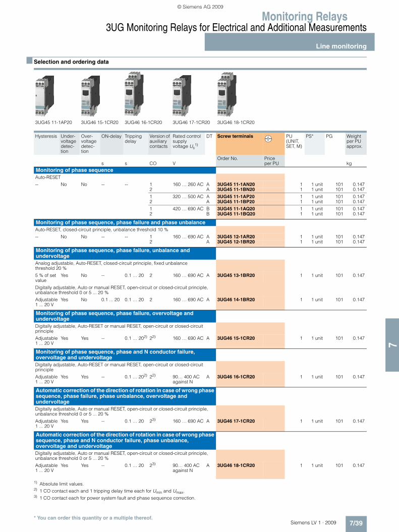
Monitoring Relays3UG Monitoring Relays for Electrical and Additional Measurements
Line monitoring
7/39Siemens LV 1 · 2009
77
■ Selection and ordering data
1) Absolute limit values.2) 1 CO contact each and 1 tripping delay time each for Umin and Umax.3) 1 CO contact each for power system fault and phase sequence correction.
3UG45 11-1AP20 3UG46 15-1CR20 3UG46 16-1CR20 3UG46 17-1CR20 3UG46 18-1CR20
Hysteresis Under-voltage detec-tion
Over-voltage detec-tion
ON-delay Tripping delay
Version of auxiliary contacts
Rated control supplyvoltage Us
1)
DT Screw terminals PU (UNIT, SET, M)
PS* PG Weight per PU approx.
s s CO VOrder No. Price
per PU kgMonitoring of phase sequenceAuto-RESET
-- No No -- -- 1 160 … 260 AC A 3UG45 11-1AN20 1 1 unit 101 0.1472 A 3UG45 11-1BN20 1 1 unit 101 0.147
1 320 … 500 AC A 3UG45 11-1AP20 1 1 unit 101 0.1472 A 3UG45 11-1BP20 1 1 unit 101 0.147
1 420 … 690 AC B 3UG45 11-1AQ20 1 1 unit 101 0.1472 B 3UG45 11-1BQ20 1 1 unit 101 0.147
Monitoring of phase sequence, phase failure and phase unbalanceAuto-RESET, closed-circuit principle, unbalance threshold 10 %
-- No No -- -- 1 160 … 690 AC A 3UG45 12-1AR20 1 1 unit 101 0.1472 A 3UG45 12-1BR20 1 1 unit 101 0.147
Monitoring of phase sequence, phase failure, unbalance and undervoltage Analog adjustable, Auto-RESET, closed-circuit principle, fixed unbalance threshold 20 %
5 % of set value
Yes No -- 0.1 … 20 2 160 … 690 AC A 3UG45 13-1BR20 1 1 unit 101 0.147
Digitally adjustable, Auto or manual RESET, open-circuit or closed-circuit principle, unbalance threshold 0 or 5 ... 20 %
Adjustable 1 ... 20 V
Yes No 0.1 ... 20 0.1 … 20 2 160 … 690 AC A 3UG46 14-1BR20 1 1 unit 101 0.147
Monitoring of phase sequence, phase failure, overvoltage and undervoltage Digitally adjustable, Auto-RESET or manual RESET, open-circuit or closed-circuit principle
Adjustable 1 ... 20 V
Yes Yes -- 0.1 … 202) 22) 160 … 690 AC A 3UG46 15-1CR20 1 1 unit 101 0.147
Monitoring of phase sequence, phase and N conductor failure, overvoltage and undervoltageDigitally adjustable, Auto-RESET or manual RESET, open-circuit or closed-circuit principle
Adjustable 1 ... 20 V
Yes Yes -- 0.1 … 202) 22) 90… 400 ACagainst N
A 3UG46 16-1CR20 1 1 unit 101 0.147
Automatic correction of the direction of rotation in case of wrong phase sequence, phase failure, phase unbalance, overvoltage and undervoltage Digitally adjustable, Auto or manual RESET, open-circuit or closed-circuit principle, unbalance threshold 0 or 5 ... 20 %
Adjustable 1 ... 20 V
Yes Yes -- 0.1 … 20 23) 160 … 690 AC A 3UG46 17-1CR20 1 1 unit 101 0.147
Automatic correction of the direction of rotation in case of wrong phase sequence, phase and N conductor failure, phase unbalance, overvoltage and undervoltage Digitally adjustable, Auto or manual RESET, open-circuit or closed-circuit principle, unbalance threshold 0 or 5 ... 20 %
Adjustable 1 ... 20 V
Yes Yes -- 0.1 … 20 23) 90… 400 ACagainst N
A 3UG46 18-1CR20 1 1 unit 101 0.147
* You can order this quantity or a multiple thereof.
LV1_09_Gesamt_EN.book Seite 39 Mittwoch, 11. Februar 2009 3:54 15
© Siemens AG 2009

Monitoring Relays3UG Monitoring Relays for Electrical and Additional Measurements
Line monitoring
7/40 Siemens LV 1 · 2009
7
1) Absolute limit values.2) 1 CO contact each and 1 tripping delay time each for Umin and Umax.3) 1 CO contact each for power system fault and phase sequence correction.
3UG45 11-2BP20 3UG45 12-2BR20
Hysteresis Under-voltage detec-tion
Over-voltage detec-tion
ON-delay Tripping delay
Version of auxiliary contacts
Rated control supply voltage Us
1)
DT Spring-type terminals
PU (UNIT, SET, M)
PS* PG Weight per PU approx.
s s CO VOrder No. Price
per PU kg
Monitoring of phase sequenceAuto-RESET
-- No No -- -- 1 160 … 260 AC B 3UG45 11-2AN20 1 1 unit 101 0.1472 B 3UG45 11-2BN20 1 1 unit 101 0.147
1 320 … 500 AC A 3UG45 11-2AP20 1 1 unit 101 0.1472 B 3UG45 11-2BP20 1 1 unit 101 0.147
1 420 … 690 AC B 3UG45 11-2AQ20 1 1 unit 101 0.1472 B 3UG45 11-2BQ20 1 1 unit 101 0.147
Monitoring of phase sequence, phase failure and phase unbalanceAuto-RESET, closed-circuit principle, unbalance threshold 10 %
-- No No -- -- 1 160 … 690 AC A 3UG45 12-2AR20 1 1 unit 101 0.1472 A 3UG45 12-2BR20 1 1 unit 101 0.147
Monitoring of phase sequence, phase failure, unbalance and undervoltage Analogically adjustable, Auto-RESET, closed-circuit principle, unbalance threshold 20 %
5 % of set value
Yes No -- 0.1 ... 20 2 160 … 690 AC A 3UG45 13-2BR20 1 1 unit 101 0.147
Digitally adjustable, Auto or manual RESET, open-circuit or closed-circuit principle, unbalance threshold 0 or 5 ... 20 %
Adjustable 1 ... 20 V
Yes No 0 ... 20 0.1 ... 20 2 160 … 690 AC A 3UG46 14-2BR20 1 1 unit 101 0.147
Monitoring of phase sequence, phase failure, overvoltage and undervoltage Digitally adjustable, Auto-RESET or manual RESET, open-circuit or closed-circuit principle
Adjustable 1 ... 20 V
Yes Yes -- 0.1 ... 202) 22) 160 … 690 AC A 3UG46 15-2CR20 1 1 unit 101 0.140
Monitoring of phase sequence, phase and N conductor failure, overvoltage and undervoltage Digitally adjustable, Auto-RESET or manual RESET, open-circuit or closed-circuit principle
Adjustable 1 ... 20 V
Yes Yes -- 0.1 ... 202) 22) 90… 400 ACagainst N
A 3UG46 16-2CR20 1 1 unit 101 0.147
Automatic correction of the direction of rotation in case of wrong phase sequence, phase failure, phase unbalance, overvoltage and undervoltage Digitally adjustable, Auto or manual RESET, open-circuit or closed-circuit principle, unbalance threshold 0 or 5 ... 20 %
Adjustable 1 ... 20 V
Yes Yes -- 0.1 ... 20 23) 160 … 690 AC B 3UG46 17-2CR20 1 1 unit 101 0.147
Automatic correction of the direction of rotation in case of wrong phase sequence, phase and N conductor failure, phase unbalance, overvoltage and undervoltage Digitally adjustable, Auto or manual RESET, open-circuit or closed-circuit principle, unbalance threshold 0 or 5 ... 20 %
Adjustable 1 ... 20 V
Yes Yes -- 0.1 ... 20 23) 90… 400 ACagainst N
B 3UG46 18-2CR20 1 1 unit 101 0.147
* You can order this quantity or a multiple thereof.
LV1_09_Gesamt_EN.book Seite 40 Mittwoch, 11. Februar 2009 3:54 15
© Siemens AG 2009

Monitoring Relays3UG Monitoring Relays for Electrical and Additional Measurements
Line monitoring
7/41Siemens LV 1 · 2009
77
■ Accessories
1) Computer labeling system for individual inscription of unit labeling plates available from: murrplastik Systemtechnik GmbH. http://www.murrplastik.com
Version DT Order No. Price per PU
PU (UNIT, SET, M)
PS* PG Weight per PU approx.
kgBlank labels
Blank labels, 20 mm x 7 mm, pastel turquoise1)
C 3RT19 00-1SB20 100 340units
101 0.200
Push-in lugs and covers
3RP19 03
Push-in lugs For screw fixing,2 units are required for each device
} 3RP19 03 1 10 units 101 0.002
3RP19 02
Sealable covers For securing against unauthorized adjustment of setting knobs
} 3RP19 02 1 5 units 101 0.004
* You can order this quantity or a multiple thereof.
LV1_09_Gesamt_EN.book Seite 41 Mittwoch, 11. Februar 2009 3:54 15
© Siemens AG 2009

Monitoring Relays3UG Monitoring Relays for Electrical and Additional Measurements
Voltage monitoring
7/42 Siemens LV 1 · 2009
7
■ Overview
The relays monitor single-phase AC voltages (rms value) and DC voltages against the set threshold value for overshoot and undershoot. The devices differ with regard to their power supply (internal or external).
■ Benefits
• Versions with wide voltage supply range• Variably adjustable to overvoltage, undervoltage or range
monitoring• Freely configurable delay times and
RESET response• Width 22.5 mm• Display of ACTUAL value and status messages• All versions with removable terminals• All versions with screw terminals or alternatively with spring-
type terminals
■ Application
• Protection of a plant against destruction due to overvoltage• Switch-on of a plant at a defined voltage and higher• Protection against overloaded supply voltages, particularly
with battery power• Threshold switch for analog signals from 0.1 ... 10 V
LV1_09_Gesamt_EN.book Seite 42 Mittwoch, 11. Februar 2009 3:54 15
© Siemens AG 2009

Monitoring Relays3UG Monitoring Relays for Electrical and Additional Measurements
Voltage monitoring
7/43Siemens LV 1 · 2009
77
■ Selection and ordering data
1) Absolute limit values.
■ Accessories
1) Computer labeling system for individual inscription of unit labeling platesavailable from:
murrplastik Systemtechnik GmbH. http://www.murrplastik.com
Measuring range Hysteresis Rated control supply voltage Us
DT Screw terminals PU (UNIT,
SET, M)PS* PG Weight
per PU approx.
V V VOrder No. Price
per PU kgInternal power supply without auxiliary voltage, ON-delay and tripping delay can be adjusted separately 0.1 ... 20 s
Digitally adjustable, LCD, Auto-RESET or manual RESET, open-circuit or closed-circuit principle,1 CO contact
17 … 275 AC/DC 0.1...150 17 … 275 AC/DC1) A 3UG46 33-1AL30 1 1 unit 101 0.147
Supplied from an external auxiliary voltage, tripping delay adjustable 0.1 ... 20 s
3UG46 31-1AA30
Digitally adjustable, LCD, Auto-RESET or manual RESET, open-circuit or closed-circuit principle, 1 CO contact
0.1 … 60 AC/DC 0.1...30 24 AC/DC A 3UG46 31-1AA30 1 1 unit 101 0.14710 … 600 AC/DC 0.1...300 A 3UG46 32-1AA30 1 1 unit 101 0.147
0.1 … 60 AC/DC 0.1...30 24 … 240 AC/DC A 3UG46 31-1AW30 1 1 unit 101 0.14710 … 600 AC/DC 0.1...300 A 3UG46 32-1AW30 1 1 unit 101 0.147
Measuring range Hysteresis Rated control supply voltage Us
1)DT Spring-type
terminalsPU (UNIT, SET, M)
PS* PG Weight per PU approx.
V V VOrder No. Price
per PU kgInternal power supply without auxiliary voltage, ON-delay and tripping delay can be adjusted separately 0.1 ... 20 s
3UG46 33-2AL30
Digitally adjustable, LCD, Auto-RESET or manual RESET, open-circuit or closed-circuit principle, 1 CO contact
17 … 275 AC/DC 0.1 ... 150 17 … 275 AC/DC1) A 3UG46 33-2AL30 1 1 unit 101 0.147
Supplied from an external auxiliary voltage, tripping delay adjustable 0.1 ... 20 s
Digitally adjustable, LCD, Auto-RESET or manual RESET, open-circuit or closed-circuit principle, 1 CO contact
0.1 … 60 AC/DC 0.1 ... 30 24 AC/DC B 3UG46 31-2AA30 1 1 unit 101 0.14710 … 600 AC/DC 0.1 ... 300 B 3UG46 32-2AA30 1 1 unit 101 0.147
0.1 … 60 AC/DC 0.1 ... 30 24 … 240 AC/DC B 3UG46 31-2AW30 1 1 unit 101 0.14710 … 600 AC/DC 0.1 ... 300 B 3UG46 32-2AW30 1 1 unit 101 0.147
Version DT Order No. Price per PU
PU (UNIT, SET, M)
PS* PG Weight per PU approx.
kgBlank labels
Blank labels, 20 mm x 7 mm, pastel turquoise1)
C 3RT19 00-1SB20 100 340units
101 0.200
Push-in lugs and covers
3RP19 03
Push-in lugs For screw fixing,2 units are required for each device
} 3RP19 03 1 10units
101 0.002
3RP19 02
Sealable covers For securing against unauthorized adjustment of setting knobs
} 3RP19 02 1 5units
101 0.004
* You can order this quantity or a multiple thereof.
LV1_09_Gesamt_EN.book Seite 43 Mittwoch, 11. Februar 2009 3:54 15
© Siemens AG 2009

Monitoring Relays3UG Monitoring Relays for Electrical and Additional Measurements
Current monitoring
7/44 Siemens LV 1 · 2009
7
■ Overview
The relays monitor single-phase AC currents (rms value) and DC currents against the set threshold value for overshoot and under-shoot. They differ with regard to their measuring ranges and supply voltage types.
■ Benefits
• Versions with wide voltage supply range• Variably adjustable to overvoltage, undervoltage or range
monitoring• Freely configurable delay times and
RESET response• Width 22.5 mm• Display of ACTUAL value and status messages• All versions with removable terminals• All versions with screw terminals or alternatively with spring-
type terminals
■ Application
• Overcurrent and undercurrent monitoring• Monitoring the functionality of electrical loads• Open-circuit monitoring• Threshold switch for analog signals from 4 ... 20 mA
LV1_09_Gesamt_EN.book Seite 44 Mittwoch, 11. Februar 2009 3:54 15
© Siemens AG 2009

Monitoring Relays3UG Monitoring Relays for Electrical and Additional Measurements
Current monitoring
7/45Siemens LV 1 · 2009
77
■ Selection and ordering data
1) No electrical isolation. Load supply voltage 24 V.2) Electrical isolation between control circuit and measuring circuit.
Load supply voltage for safe isolation max. 300 V, for simple isolation max. 500 V.
■ Accessories
1) Computer labeling system for individual inscription of unit labeling plates available from: murrplastik Systemtechnik GmbH. http://www.murrplastik.com
Measuring range Hysteresis Rated control supply voltage Us
DT Screw terminals PU (UNIT, SET, M)
PS* PG Weight per PU approx.
VOrder No. Price
per PU kgMonitoring of undercurrent and overcurrent, ON-delay and tripping delay can be adjusted separately 0.1 ... 20 s
3UG46 21-1AA30
Digitally adjustable, LCD, Auto-RESET or manual RESET, open-circuit or closed-circuit principle, 1 CO contact
AC/DC 3 … 500 mA 0.1 ... 250 mA 24 AC/DC1) A 3UG46 21-1AA30 1 1 unit 101 0.147AC/DC 0.05 … 10 A 0.01 ... 5 A A 3UG46 22-1AA30 1 1 unit 101 0.147
AC/DC 3 … 500 mA 0.1 ... 250 mA 24 … 240 AC/DC2) A 3UG46 21-1AW30 1 1 unit 101 0.147AC/DC 0.05 … 10 A 0.01 ... 5 A A 3UG46 22-1AW30 1 1 unit 101 0.147
Measuring range Hysteresis Rated control supply voltage Us
DT Spring-type terminals
PU (UNIT, SET, M)
PS* PG Weight per PU approx.
VOrder No. Price
per PU kgMonitoring of undercurrent and overcurrent, ON-delay and tripping delay can be adjusted separately 0.1 ... 20 s
3UG46 22-2AW30
Digitally adjustable, LCD, Auto-RESET or manual RESET, open-circuit or closed-circuit principle, 1 CO contact
AC/DC 3 … 500 mA 0.1 ... 250 mA 24 AC/DC1) B 3UG46 21-2AA30 1 1 unit 101 0.147AC/DC 0.05 … 10 A 0.01 ... 5 A B 3UG46 22-2AA30 1 1 unit 101 0.147
AC/DC 3 … 500 mA 0.1 ... 250 mA 24 … 240 AC/DC2) B 3UG46 21-2AW30 1 1 unit 101 0.147AC/DC 0.05 … 10 A 0.01 ... 5 A A 3UG46 22-2AW30 1 1 unit 101 0.147
Version DT Order No. Price per PU
PU (UNIT, SET, M)
PS* PG Weight per PU approx.
kgBlank labels
Blank labels, 20 mm x 7 mm, pastel turquoise1)
C 3RT19 00-1SB20 100 340 units 101 0.200
Push-in lugs and covers
3RP19 03
Push-in lugs For screw fixing,2 units are required for each device
} 3RP19 03 1 10 units 101 0.002
3RP19 02
Sealable covers For securing against unauthorized adjustment of setting knobs
} 3RP19 02 1 5 units 101 0.004
* You can order this quantity or a multiple thereof.
LV1_09_Gesamt_EN.book Seite 45 Mittwoch, 11. Februar 2009 3:54 15
© Siemens AG 2009

Monitoring Relays3UG Monitoring Relays for Electrical and Additional Measurements
Power factor and active current monitoring
7/46 Siemens LV 1 · 2009
7
■ Overview
The 3UG46 41 power factor and active current monitoring de-vice enables the load monitoring of motors.
Whereas power factor monitoring is used above all for monitor-ing no-load operation, the active current monitoring option can be used to observe and evaluate the load factor over the entire torque range.
■ Benefits
• Can be used world-wide thanks to wide voltage range from 90 ... 690 V1)
• Monitoring of even small single-phase motors with a no-load supply current below 0.5 A
• Simple determination of threshold values through the direct collection of measured variables on motor loading
• Range monitoring and active current measurement enable de-tection of cable breaks between control cabinets and motors, as well as phase failures
• Power factor or active current can be selected as measure-ment principle
1) Absolute limit values.
■ Application
• No-load monitoring and load shedding, such as in the event of a V-belt tear
• Underload monitoring in the low performance range, e. g. in the event of pump no-load operation
• Monitoring of overload, e. g. due to a dirty filter system• Simple power factor monitoring in networks for control of
correction equipment• Broken cable between control cabinet and motor
LV1_09_Gesamt_EN.book Seite 46 Mittwoch, 11. Februar 2009 3:54 15
© Siemens AG 2009

Monitoring Relays3UG Monitoring Relays for Electrical and Additional Measurements
Power factor and active current monitoring
7/47Siemens LV 1 · 2009
77
■ Selection and ordering data
• Relay for monitoring the power factor and the active current Ires (p.f. x I)
• Suitable for single- and three-phase currents• Digital adjustable, with illuminated LCD• Overshoot, undershoot or range monitoring
• Upper and lower threshold value can be adjusted separately• Permanent display of actual value and tripping state• 1 changeover contact each for undershoot/overshoot• All terminals are removable• Width 22.5 mm
1) Absolute limit values.
■ Accessories
1) Computer labeling system for individual inscription of unit labeling plates available from: murrplastik Systemtechnik GmbH. http://www.murrplastik.com
Measuring range Hysteresis ON-delay OFF-delay Rated control supply voltage Us
1)
DT Screw terminals PU (UNIT, SET, M)
PS* PG Weight per PU approx.
For power factor
For active current
For power factor
For active current
AC 50/60 Hz
p.f. A p.f. A s s VOrder No. Price
per PU kg
0.10 ... 0.99 0.2 ... 10.0 0.1 0.1 ... 2.0 0 ... 99 0.1 ... 20.0 90 ... 690 A 3UG46 41-1CS20 1 1 unit 101 0.147
Measuring range Hysteresis ON-delay OFF-delay Rated control supply voltage Us
1)
DT Spring-type terminals
PU (UNIT, SET, M)
PS* PG Weight per PU approx.
For power factor
For active current
For power factor
For active current
AC 50/60 Hz
p.f. A p.f. A s s VOrder No. Price
per PU kg
0.10 ... 0.99 0.2 ... 10.0 0.1 0.1 ... 2.0 0 ... 99 0.1 ... 20.0 90 ... 690 B 3UG46 41-2CS20 1 1 unit 101 0.147
Version DT Order No. Price per PU
PU (UNIT, SET, M)
PS* PG Weight per PU approx.
kgBlank labels
Blank labels, 20 mm x 7 mm, pastel turquoise1)
C 3RT19 00-1SB20 100 340 units 101 0.200
Push-in lugs and covers
3RP19 03
Push-in lugs For screw fixing,2 units are required for each device
} 3RP19 03 1 10 units 101 0.002
3RP19 02
Sealable covers For securing against unauthorized adjustment of setting knobs
} 3RP19 02 1 5 units 101 0.004
* You can order this quantity or a multiple thereof.
LV1_09_Gesamt_EN.book Seite 47 Mittwoch, 11. Februar 2009 3:54 15
© Siemens AG 2009

Monitoring Relays3UG Monitoring Relays for Electrical and Additional MeasurementsResidual current monitoring:Residual-current monitoring relays
7/48 Siemens LV 1 · 2009
7
■ Overview
The 3UG46 24 residual current monitoring relay is used together with the 3UL22 summation current transformer for plant monitoring.
■ Application
• Plant monitoring
■ Selection and ordering data
• Relay for monitoring residual currents IΔn 0.3 ... 40 A• For 3UL22 summation current transformers with feed-through
opening 40 ... 120 mm• Digital adjustable, with illuminated LCD• Separately adjustable limit value and warning threshold
• Permanent display of actual value and tripping state• 1 CO contact each for limit violation and warning threshold• All terminals are removable• Width 22.5 mm
For 3UL22 summation current transformers see page 7/50.1) LSB: Smallest adjustable value, transformer-dependent, ≤ 1 % of IΔn.2) Absolute limit values.
Display range
Setting range
Hysteresis ON/trip-ping delay time
Rated control supply voltage Us
2)
DT Screw terminals PU (UNIT, SET, M)
PS* PG Weight per PU approx.Limit value Warning
valueOrder No. Price
per PU
A A A A s V kg
10 ... 120 % of IΔn
10 ... 100 % of IΔn
LSB1) up to 50 % of IΔn
5 % of IΔn
0.1 ... 20 90 ... 690 A 3UG46 24-1CS20 1 1 unit 101 0.147
Display range
Setting range
Hysteresis ON/trip-ping delay time
Rated control supply voltage Us
2)
DT Spring-type terminals
PU (UNIT, SET, M)
PS* PG Weight per PU approx.
Limit value Warning value
Order No. Price per PU
A A A A s V kg
10 ... 120 % of IΔn
10 ... 100 % of IΔn
LSB1) up to 50 % of IΔn
5 % of IΔn
0.1 ... 20 90 ... 690 B 3UG46 24-2CS20 1 1 unit 101 0.130
* You can order this quantity or a multiple thereof.
LV1_09_Gesamt_EN.book Seite 48 Mittwoch, 11. Februar 2009 3:54 15
© Siemens AG 2009
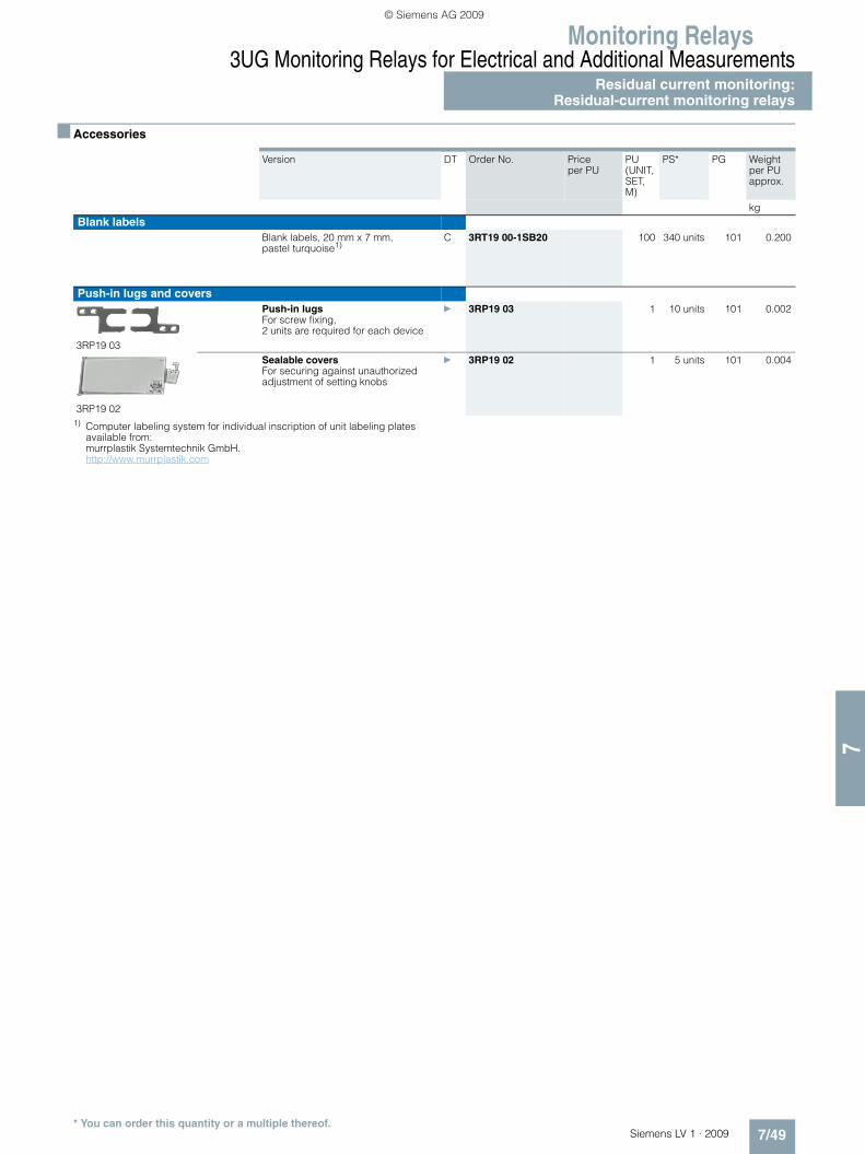
Monitoring Relays3UG Monitoring Relays for Electrical and Additional Measurements
Residual current monitoring:Residual-current monitoring relays
7/49Siemens LV 1 · 2009
77
■ Accessories
1) Computer labeling system for individual inscription of unit labeling plates available from: murrplastik Systemtechnik GmbH.http://www.murrplastik.com
Version DT Order No. Price per PU
PU (UNIT, SET, M)
PS* PG Weight per PU approx.
kgBlank labels
Blank labels, 20 mm x 7 mm, pastel turquoise1)
C 3RT19 00-1SB20 100 340 units 101 0.200
Push-in lugs and covers
3RP19 03
Push-in lugs For screw fixing,2 units are required for each device
} 3RP19 03 1 10 units 101 0.002
3RP19 02
Sealable covers For securing against unauthorized adjustment of setting knobs
} 3RP19 02 1 5 units 101 0.004
* You can order this quantity or a multiple thereof.
LV1_09_Gesamt_EN.book Seite 49 Mittwoch, 11. Februar 2009 3:54 15
© Siemens AG 2009

Monitoring Relays3UG Monitoring Relays for Electrical and Additional MeasurementsResidual current monitoring:Summation current transformers
7/50 Siemens LV 1 · 2009
7
■ Overview
The 3UL22 summation current transformers sense fault currents in machines and plants. Together with the 3UG46 24 residual current monitoring relay or the SIMOCODE 3UF motor manage-ment and control device they enable residual-current and ground-fault monitoring.
■ Application
• Plant monitoring
■ Selection and ordering data
Feed-through opening diameter
Rated insula-tion voltage Ui
Rated fault current IΔn
DT Screw terminals PU (UNIT, SET, M)
PS* PG Weight per PU approx.Order No. Price
per PU
mm V A kgSummation current transformers (essential accessory for 3UG46 24 or SIMOCODE 3UF)
3UL22
40 690 0.3 B 3UL22 01-1A 1 1 unit 101 0.5710.5 B 3UL22 01-2A 1 1 unit 101 0.4081 B 3UL22 01-3A 1 1 unit 101 0.324
65 690 0.3 B 3UL22 02-1A 1 1 unit 101 0.9000.5 B 3UL22 02-2A 1 1 unit 101 0.7131 B 3UL22 02-3A 1 1 unit 101 0.5686 C 3UL22 02-1B 1 1 unit 101 0.56110 C 3UL22 02-2B 1 1 unit 101 0.56316 C 3UL22 02-3B 1 1 unit 101 0.57325 C 3UL22 02-4B 1 1 unit 101 0.57540 C 3UL22 02-5B 1 1 unit 101 0.564
120 1000 0.3 B 3UL22 03-1A 1 1 unit 101 3.4350.5 B 3UL22 03-2A 1 1 unit 101 2.8101 B 3UL22 03-3A 1 1 unit 101 1.9656 C 3UL22 03-1B 1 1 unit 101 1.95510 C 3UL22 03-2B 1 1 unit 101 1.99016 C 3UL22 03-3B 1 1 unit 101 1.91725 C 3UL22 03-4B 1 1 unit 101 1.85140 C 3UL22 03-5B 1 1 unit 101 1.905
* You can order this quantity or a multiple thereof.
LV1_09_Gesamt_EN.book Seite 50 Mittwoch, 11. Februar 2009 3:54 15
© Siemens AG 2009

Monitoring Relays3UG Monitoring Relays for Electrical and Additional Measurements
Insulation monitoringfor ungrounded AC networks
7/51Siemens LV 1 · 2009
77
■ Overview
Relay for monitoring the insulation resistance between the un-grounded single or three-phase AC supply and a protective conductor• Measuring principle with superimposed DC voltage• Two selectable measuring ranges of 1 ... 110 kΩ• Stepless setting within the measuring range• Selectable:
- Auto reset function with fixed hysteresis or- Storage of the tripping operation
• Test function with test button and terminal connections on the front
• Switching output: 1 CO contact• Insulation fault indication with a red LED• Supply voltage indication with a green LED• Electro-magnetically compatible according to EN 61000-6-2
and -6-4
■ Application
The 3UG30 81 monitoring device is suitable for insulation moni-toring of AC systems with one or three phases in ungrounded networks (IT networks).
Supply voltage
The 3UG30 81-1AK20 has alternative voltage terminals. Only one supply voltage is permitted to be connected to it! Terminals A1 and A2 are used to connect 230 V AC and terminals A1 and B2 are used to connect 115 V AC.
The 3UG30 81-1AW30 has a wide-range input of 24 ... 240 V AC/DC on terminals A1 and A2.
■ Selection and ordering data
■ Accessories
Measuring range Ue
Rated control supply voltage Us
DT Screw terminals PU (UNIT, SET, M)
PS* PG Weight per PU approx.
kΩ VOrder No. Price
per PU kgInsulation monitors for ungrounded AC networks
3UG30 81-1AK20
1 ... 110 115/230 AC A 3UG30 81-1AK20 1 1 unit 101 0.327
24 ... 240 AC/DC B 3UG30 81-1AW30 1 1 unit 101 0.242
Version DT Order No. Price per PU
PU (UNIT, SET, M)
PS* PG Weight per PU approx.
kgCovers
Sealable, transparent covers C 3UG32 08-1A 1 1 unit 101 0.010
* You can order this quantity or a multiple thereof.
LV1_09_Gesamt_EN.book Seite 51 Mittwoch, 11. Februar 2009 3:54 15
© Siemens AG 2009
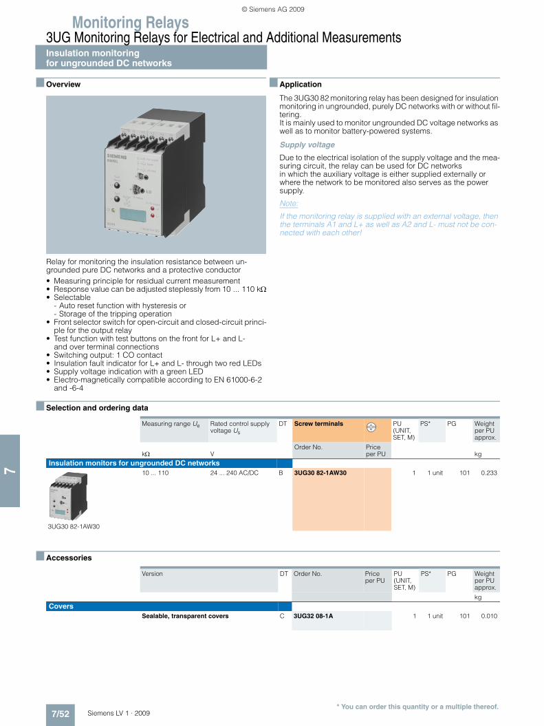
Monitoring Relays3UG Monitoring Relays for Electrical and Additional MeasurementsInsulation monitoringfor ungrounded DC networks
7/52 Siemens LV 1 · 2009
7
■ Overview
Relay for monitoring the insulation resistance between un-grounded pure DC networks and a protective conductor• Measuring principle for residual current measurement• Response value can be adjusted steplessly from 10 ... 110 kΩ• Selectable
- Auto reset function with hysteresis or - Storage of the tripping operation
• Front selector switch for open-circuit and closed-circuit princi-ple for the output relay
• Test function with test buttons on the front for L+ and L-and over terminal connections
• Switching output: 1 CO contact• Insulation fault indicator for L+ and L- through two red LEDs• Supply voltage indication with a green LED • Electro-magnetically compatible according to EN 61000-6-2
and -6-4
■ Application
The 3UG30 82 monitoring relay has been designed for insulation monitoring in ungrounded, purely DC networks with or without fil-tering.It is mainly used to monitor ungrounded DC voltage networks as well as to monitor battery-powered systems.
Supply voltage
Due to the electrical isolation of the supply voltage and the mea-suring circuit, the relay can be used for DC networks in which the auxiliary voltage is either supplied externally or where the network to be monitored also serves as the power supply.
Note:
If the monitoring relay is supplied with an external voltage, then the terminals A1 and L+ as well as A2 and L- must not be con-nected with each other!
■ Selection and ordering data
■ Accessories
Measuring range Ue Rated control supply voltage Us
DT Screw terminals PU (UNIT, SET, M)
PS* PG Weight per PU approx.
kΩ VOrder No. Price
per PU kgInsulation monitors for ungrounded DC networks
3UG30 82-1AW30
10 ... 110 24 ... 240 AC/DC B 3UG30 82-1AW30 1 1 unit 101 0.233
Version DT Order No. Price per PU
PU (UNIT, SET, M)
PS* PG Weight per PU approx.
kgCovers
Sealable, transparent covers C 3UG32 08-1A 1 1 unit 101 0.010
* You can order this quantity or a multiple thereof.
LV1_09_Gesamt_EN.book Seite 52 Mittwoch, 11. Februar 2009 3:54 15
© Siemens AG 2009

Monitoring Relays3UG Monitoring Relays for Electrical and Additional Measurements
Level monitoring:Level monitoring relays
7/53Siemens LV 1 · 2009
77
■ Overview
The 3UG45 01 level monitoring relay is used together with 2- or 3-pole sensors to monitor the levels of conductive liquids.
■ Application
• Single-point and two-point level monitoring• Overflow protection• Dry run protection• Leak monitoring
■ Selection and ordering data
• Level monitoring relay for conductive liquids• Control principle: inlet or outlet control per rotary switch• Single-point and two-point control possible• Analog adjustable sensitivity (specific resistance of the liquid)
• Analog adjustable tripping delay time• 1 yellow LED for indicating the relay state• 1 green LED for indicating the applied control supply voltage• 1 CO contact• All terminals are removable• Width 22.5 mm
For level monitoring sensors see page 7/55.1) The rated control supply voltage and the measuring circuit are not electri-
cally isolated.
Sensitivity Tripping delay time Rated control supply voltage Us
DT Screw terminals PU (UNIT, SET, M)
PS* PG Weight per PU approx.
kΩ sVAC/DC
Order No. Price per PU kg
2 ... 200 0.5 ... 10 241) A 3UG45 01-1AA30 1 1 unit 101 0.11024 ... 240 A 3UG45 01-1AW30 1 1 unit 101 0.120
Sensitivity Tripping delay time Rated control supply voltage Us
DT Spring-type terminals
PU (UNIT, SET, M)
PS* PG Weight per PU approx.
kΩ sVAC/DC
Order No. Price per PU kg
2 ... 200 0.5 ... 10 241) A 3UG45 01-2AA30 1 1 unit 101 0.11024 ... 240 A 3UG45 01-2AW30 1 1 unit 101 0.120
* You can order this quantity or a multiple thereof.
LV1_09_Gesamt_EN.book Seite 53 Mittwoch, 11. Februar 2009 3:54 15
© Siemens AG 2009
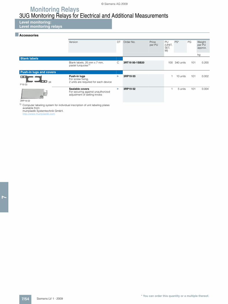
Monitoring Relays3UG Monitoring Relays for Electrical and Additional MeasurementsLevel monitoring:Level monitoring relays
7/54 Siemens LV 1 · 2009
7
■ Accessories
1) Computer labeling system for individual inscription of unit labeling plates available from: murrplastik Systemtechnik GmbH. http://www.murrplastik.com
Version DT Order No. Price per PU
PU (UNIT, SET, M)
PS* PG Weight per PU approx.
kgBlank labels
Blank labels, 20 mm x 7 mm, pastel turquoise1)
C 3RT19 00-1SB20 100 340 units 101 0.200
Push-in lugs and covers
3RP19 03
Push-in lugs For screw fixing,2 units are required for each device
} 3RP19 03 1 10 units 101 0.002
3RP19 02
Sealable covers For securing against unauthorized adjustment of setting knobs
} 3RP19 02 1 5 units 101 0.004
* You can order this quantity or a multiple thereof.
LV1_09_Gesamt_EN.book Seite 54 Mittwoch, 11. Februar 2009 3:54 15
© Siemens AG 2009

Monitoring Relays3UG Monitoring Relays for Electrical and Additional Measurements
Level monitoring:Level monitoring sensors
7/55Siemens LV 1 · 2009
77
■ Selection and ordering data
Version Assignment Application DT Order No. Price per PU
PU (UNIT, SET, M)
PS* PG Weight per PU approx.
Cable Elec-trode
kg
Level monitoring sensors (essential accessory)
3UG32 07-3A
Three-pole wire electrodes500 mm long, with Teflon insulation (PTFE), screw-in gland width A/F 22, 3/8 inch thread, PVC connecting cable, 3 x 0.5 mm2, 2 m long, max. operating tempera-ture 90 °C, max. operating pressure 10 bar
Brown Center elec-trode
The electrodes can be cut or bent to the required length before or after installation. The Teflon insulation must be removed over a length of approx. 5 mm.
Applications: For 2-point liquid level control in an insu-lating tank. One electrode each for the min. and max. value and a com-mon reference electrode.
} 3UG32 07-3A 1 1 unit 101 0.254
WhiteGreen
Not assign-able
3UG32 07-2A
Two-pole wire electrodes500 mm long, with Teflon insulation (PTFE), screw-in gland width A/F 22, 3/8 inch thread, PVC connecting cable, 3 x 0.5 mm2, 2 m long, max. operating tempera-ture 90 °C, max. operating pressure 10 bar
BrownWhite
Not assign-able
For installation see 3UG32 07-3A
Application: For alarm indication in the event of over-flow or low level and for 2-point liq-uid level control, when the conduc-tive tank is used as the reference electrode.
} 3UG32 07-2A 1 1 unit 101 0.230
3UG32 07-2B
Two-pole bow electrodeswith Teflon insulation (PTFE), screw-in gland width A/F 22, 3/8 inch thread, PVC connecting cable, 3 x 0.5 mm2, 2 m long, max. operating tempera-ture 90 °C, max. operating pressure 10 bar
Brown Gland Thanks to the small space require-ments due to lat-eral fitting, ideal for use in small con-tainers and pipes, as a leak monitor and level monitor or for warning of water entering an enclosure.
} 3UG32 07-2B 1 1 unit 101 0.128
WhiteGreen
Not assign-able
3UG32 07-1B
Single-pole bow electrodes for lateral fitting with Teflon insulation (PTFE), screw-in gland width A/F 22, 3/8 inch thread, PVC connecting cable, 3 x 0.5 mm2, 2 m long, max. operating tempera-ture 90 °C, max. operating pressure 10 bar
Brown Gland As a max. value electrode for lateral fitting or for alarm indication in con-ductive tanks or pipes.
} 3UG32 07-1B 1 1 unit 101 0.122
White Elec-trode
3UG32 07-1C
Single-pole rod electrodes for lateral fittingwith Teflon insulation (PTFE), screw-in gland width A/F 22, 3/8 inch thread, PVC connecting cable, 3 x 0.5 mm2, 2 m long, max. operat-ing temperature 90 °C, max. operat-ing pressure 10 bar
Brown Gland For high flow velocities or for intensively spar-kling fluids.
C 3UG32 07-1C 1 1 unit 101 0.144
White Elec-trode
* You can order this quantity or a multiple thereof.
LV1_09_Gesamt_EN.book Seite 55 Mittwoch, 11. Februar 2009 3:54 15
© Siemens AG 2009

Monitoring Relays3UG Monitoring Relays for Electrical and Additional Measurements
Speed monitoring
7/56 Siemens LV 1 · 2009
7
■ Overview
The 3UG46 51 monitoring relay is used together with a sensor to monitor drives for overspeed and/or underspeed.
Furthermore, this relay is ideal for all functions where a continu-ous pulse signal needs to be monitored (e. g. belt travel monitor-ing, completeness monitoring, passing monitoring, clock-time monitoring).
■ Application
• Slip or tear of a belt drive• Overload monitoring• Transport monitoring for completeness
■ Selection and ordering data
• Relay for speed monitoring in min -1 (rpm)• Two- or three-wire sensor with mechanical or electronic
switching output can be connected• Two-wire NAMUR sensor can be connected• Integrated sensor supply 24 V DC/50 mA• Input frequency 0.1 ... 2200 pulses min -1
(0.0017 ... 36.7 Hz)• With or without enable signal for the drive to be monitored
• Digital adjustable, with illuminated LCD• Overshoot, undershoot or range monitoring• Number of pulses per revolution can be adjusted• Upper and lower threshold value can be adjusted separately• Auto, manual or remote RESET options after tripping• Permanent display of actual value and tripping state• 1 CO contact• All terminals are removable• Width 22.5 mm
1) The rated control supply voltage and the measuring circuit are not electri-cally isolated.
Measuring range
Hysteresis ON-delay time
Tripping delay time
Pulses per revo-lution
Rated control supply voltage Us
DT Screw terminals PU (UNIT, SET, M)
PS* PG Weight per PU approx.
AC/DC
rpm rpm s s VOrder No. Price
per PU kg
0.1 ... 2200 OFF, 0.1 ... 99.9 0 ... 900 0.1 ... 99.9 1 ... 10 241) A 3UG46 51-1AA30 1 1 unit 101 0.12024 ... 240 A 3UG46 51-1AW30 1 1 unit 101 0.130
Measuring range
Hysteresis ON-delay time
Tripping delay time
Pulses per revo-lution
Rated control supply voltage Us
DT Spring-type terminals
PU (UNIT, SET, M)
PS* PG Weight per PU approx.
AC/DC
rpm rpm s s VOrder No. Price
per PU kg
0.1 ... 2200 OFF, 0.1 ... 99.9 0 ... 900 0.1 ... 99.9 1 ... 10 241) A 3UG46 51-2AA30 1 1 unit 101 0.12024 ... 240 A 3UG46 51-2AW30 1 1 unit 101 0.130
* You can order this quantity or a multiple thereof.
LV1_09_Gesamt_EN.book Seite 56 Mittwoch, 11. Februar 2009 3:54 15
© Siemens AG 2009

Monitoring Relays3UG Monitoring Relays for Electrical and Additional Measurements
Speed monitoring
7/57Siemens LV 1 · 2009
77
■ Accessories
1) Computer labeling system for individual inscription of unit labeling plates available from: murrplastik Systemtechnik GmbH. http://www.murrplastik.com
Version DT Order No. Price per PU
PU (UNIT, SET, M)
PS* PG Weight per PU approx.
kgBlank labels
Blank labels, 20 mm x 7 mm, pastel turquoise1)
C 3RT19 00-1SB20 100 340 units 101 0.200
Push-in lugs and covers
3RP19 03
Push-in lugs For screw fixing,2 units are required for each device
} 3RP19 03 1 10 units 101 0.002
3RP19 02
Sealable covers For securing against unauthorized adjustment of setting knobs
} 3RP19 02 1 5 units 101 0.004
* You can order this quantity or a multiple thereof.
LV1_09_Gesamt_EN.book Seite 57 Mittwoch, 11. Februar 2009 3:54 15
© Siemens AG 2009

Monitoring Relays3RS10, 3RS11 Temperature Monitoring Relays
Relays, analogically adjustable, for 1 sensor
7/58 Siemens LV 1 · 2009
7
■ Overview
The 3RS10/3RS11 analog temperature monitoring relays can be used for measuring temperatures in solid, liquid and gas media. The temperature is detected by the sensors in the medium, eval-uated by the device and monitored for overshoot or undershoot. When the threshold values are reached, the output relay switches on or off depending on the parameterization.
■ Benefits
• All devices except for 24 V AC/DC feature electrical isolation• Extremely easy operation using a rotary potentiometer• Variable hysteresis• Adjustable working principle for devices with
2 threshold values• All versions with removable terminals• All versions with screw terminals, many versions alternatively
with spring-type connections
■ Application
The analogically adjustable SIRIUS 3RS10/3RS11 temperature monitoring relays can be used in almost any application in which temperature overshoot or undershoot is not permitted, e. g. in the monitoring of set temperature limits and the output of alarm messages for:• Motor and system protection• Control cabinet temperature monitoring• Freeze monitoring• Temperature limits for process variables e. g. in the packaging
industry or electroplating• Controlling equipment and machines such as heating, climate
and ventilation systems, solar collectors, heat pumps or warm water supplies
• Motor, bearing and gear oil monitoring• Monitoring of coolants
LV1_09_Gesamt_EN.book Seite 58 Mittwoch, 11. Februar 2009 3:54 15
© Siemens AG 2009

Monitoring Relays3RS10, 3RS11 Temperature Monitoring Relays
Relays, analogically adjustable, for 1 sensor
7/59Siemens LV 1 · 2009
77
■ Selection and ordering data
• Temperature monitoring relays with resistance sensors or thermoelements
• Temperature range -55 °C ... +1000 °C, depending on sensor type
• Wide-range voltage versions are electrically isolated.• Analog adjustable, setting accuracy ±5 %• Versions with 2 separately adjustable threshold values and
adjustable open/closed-circuit principle
• Hysteresis for threshold value 1 is adjustable (2 ... 20 %), hysteresis for threshold 2 is non-adjustable (5 %)
• 1 NC + 1 NO for versions with one threshold value• 1 CO for threshold value 1 and 1 NO for threshold value 2• All terminals are removable• Width 22.5 mm
Sensor Function Measuring range
Rated control supply voltage Us AC 50/60 Hz
DT Screw terminals PU (UNIT, SET, M)
PS* PG Weight per PU approx.
°C VOrder No. Price
per PU kgAnalogically adjustable, 1 threshold value, width 22.5 mm; closed-circuit principle; without memory; 1 NO + 1 NC
3RS10 00-1CD10
3RS11 00-1CK30
PT100 (resistance sensor)
Overshoot - 50 … + 50 24 AC/DC C 3RS10 00-1CD00 1 1 unit 101 0.150110/230 AC A 3RS10 00-1CK00 1 1 unit 101 0.190
0 … + 100 24 AC/DC C 3RS10 00-1CD10 1 1 unit 101 0.145110/230 AC A 3RS10 00-1CK10 1 1 unit 101 0.189
0 … + 200 24 AC/DC C 3RS10 00-1CD20 1 1 unit 101 0.145110/230 AC A 3RS10 00-1CK20 1 1 unit 101 0.186
Under-shoot
- 50 … + 50 24 AC/DC C 3RS10 10-1CD00 1 1 unit 101 0.150110/230 AC A 3RS10 10-1CK00 1 1 unit 101 0.186
0 … + 100 24 AC/DC C 3RS10 10-1CD10 1 1 unit 101 0.150110/230 AC C 3RS10 10-1CK10 1 1 unit 101 0.190
0 … + 200 24 AC/DC C 3RS10 10-1CD20 1 1 unit 101 0.150110/230 AC C 3RS10 10-1CK20 1 1 unit 101 0.191
Type J (thermo-element)
Overshoot 0 … + 200 24 AC/DC A 3RS11 00-1CD20 1 1 unit 101 0.150110/230 AC C 3RS11 00-1CK20 1 1 unit 101 0.190
0 … + 600 24 AC/DC C 3RS11 00-1CD30 1 1 unit 101 0.149110/230 AC C 3RS11 00-1CK30 1 1 unit 101 0.190
Type K (thermo-element)
Overshoot 0 … + 200 24 AC/DC C 3RS11 01-1CD20 1 1 unit 101 0.150110/230 AC C 3RS11 01-1CK20 1 1 unit 101 0.190
0 … + 600 24 AC/DC C 3RS11 01-1CD30 1 1 unit 101 0.150110/230 AC C 3RS11 01-1CK30 1 1 unit 101 0.190
+ 500 … + 1000
24 AC/DC C 3RS11 01-1CD40 1 1 unit 101 0.150110/230 AC C 3RS11 01-1CK40 1 1 unit 101 0.190
Analogically adjustable for warning and disconnection (2 threshold values), 22.5 mm width, open/closed-circuit principle switchable; without memory; 1 NO + 1 CO
3RS10 20-1DD00
3RS11 21-1DD40
PT100 (resistance sensor)
Overshoot - 50 … + 50 24 AC/DC C 3RS10 20-1DD00 1 1 unit 101 0.16624 … 240 AC/DC C 3RS10 20-1DW00 1 1 unit 101 0.175
0 … + 100 24 AC/DC C 3RS10 20-1DD10 1 1 unit 101 0.16424 … 240 AC/DC C 3RS10 20-1DW10 1 1 unit 101 0.175
0 … + 200 24 AC/DC C 3RS10 20-1DD20 1 1 unit 101 0.16624 … 240 AC/DC A 3RS10 20-1DW20 1 1 unit 101 0.175
Under-shoot
-50 … + 50 24 AC/DC C 3RS10 30-1DD00 1 1 unit 101 0.16524 … 240 AC/DC C 3RS10 30-1DW00 1 1 unit 101 0.174
0 … + 100 24 AC/DC C 3RS10 30-1DD10 1 1 unit 101 0.16624 … 240 AC/DC C 3RS10 30-1DW10 1 1 unit 101 0.175
0 … + 200 24 AC/DC C 3RS10 30-1DD20 1 1 unit 101 0.16324 … 240 AC/DC C 3RS10 30-1DW20 1 1 unit 101 0.173
Type J (thermo-element)
Overshoot 0 … + 200 24 AC/DC C 3RS11 20-1DD20 1 1 unit 101 0.16524 … 240 AC/DC C 3RS11 20-1DW20 1 1 unit 101 0.175
0 … + 600 24 AC/DC C 3RS11 20-1DD30 1 1 unit 101 0.16724 … 240 AC/DC C 3RS11 20-1DW30 1 1 unit 101 0.175
Type K (thermo-element)
Overshoot 0 ... + 200 24 … 240 AC/DC C 3RS11 21-1DW20 1 1 unit 101 0.179
0 ... + 600 24 … 240 AC/DC C 3RS11 21-1DW30 1 1 unit 101 0.176
+ 500 … + 1000
24 AC/DC C 3RS11 21-1DD40 1 1 unit 101 0.167
* You can order this quantity or a multiple thereof.
LV1_09_Gesamt_EN.book Seite 59 Mittwoch, 11. Februar 2009 3:54 15
© Siemens AG 2009

Monitoring Relays3RS10, 3RS11 Temperature Monitoring Relays
Relays, analogically adjustable, for 1 sensor
7/60 Siemens LV 1 · 2009
7
• Temperature monitoring relays with resistance sensors or thermoelements
• Temperature range -55 °C ... +1000 °C, depending on sensor type
• Wide-range voltage versions are electrically isolated.• Analog adjustable, setting accuracy ±5 %• Versions with 2 separately adjustable threshold values and
adjustable open/closed-circuit principle
• Hysteresis for threshold value 1 is adjustable (2 ... 20 %), hysteresis for threshold 2 is non-adjustable (5 %)
• 1 NC + 1 NO for versions with one threshold value• 1 CO for threshold value 1 and 1 NO for threshold value 2• All terminals are removable• Width 22.5 mm
■ Accessories
1) Computer labeling system for individual inscription of unit labeling plates available from: murrplastik Systemtechnik GmbH. http://www.murrplastik.com
Sensor Function Measuring range
Rated control supply voltage Us AC 50/60 Hz
DT Spring-typeterminals
PU (UNIT, SET, M)
PS* PG Weight per PU approx.
°C VOrder No. Price
per PU kgAnalogically adjustable, 1 threshold value, width 22.5 mm; closed-circuit principle; without memory; 1 NO + 1 NC
3RS10 00-2CD10
PT100 (resistance sensor)
Overshoot - 50 … + 50 24 AC/DC C 3RS10 00-2CD00 1 1 unit 101 0.125110/230 AC C 3RS10 00-2CK00 1 1 unit 101 0.163
0 … + 100 24 AC/DC C 3RS10 00-2CD10 1 1 unit 101 0.125110/230 AC C 3RS10 00-2CK10 1 1 unit 101 0.165
0 … + 200 24 AC/DC C 3RS10 00-2CD20 1 1 unit 101 0.121110/230 AC C 3RS10 00-2CK20 1 1 unit 101 0.165
Type J(thermo-element)
Overshoot 0 ... + 200 24 AC/DC C 3RS11 00-2CD20 1 1 unit 101 0.125
Analogically adjustable for warning and disconnection (2 threshold values), 22.5 mm width, open/closed-circuit principle switchable; without memory; 1 NO + 1 CO
3RS11 20-2DD20
PT100 (resistance sensor)
Overshoot 0 ... + 200 24 … 240 AC/DC C 3RS10 20-2DW20 1 1 unit 101 0.153
Undershoot 0 ... + 200 24 AC/DC C 3RS10 30-2DD20 1 1 unit 101 0.145
Type J(thermo-element)
Overshoot 0 ... + 200 24 AC/DC C 3RS11 20-2DD20 1 1 unit 101 0.140
Version DT Order No. Price per PU
PU (UNIT, SET, M)
PS* PG Weight per PU approx.
kgBlank labels
Blank labels, 20 mm x 7 mm, pastel turquoise1)
C 3RT19 00-1SB20 100 340units
101 0.200
Push-in lugs and covers
3RP19 03
Push-in lugs For screw fixing,2 units are required for each device
} 3RP19 03 1 10 units 101 0.002
3RP19 02
Sealable covers For securing against unauthorized adjustment of setting knobs
} 3RP19 02 1 5 units 101 0.004
* You can order this quantity or a multiple thereof.
LV1_09_Gesamt_EN.book Seite 60 Mittwoch, 11. Februar 2009 3:54 15
© Siemens AG 2009

Monitoring Relays3RS10, 3RS11 Temperature Monitoring Relays
Relays, digitally adjustable, for 1 sensor
7/61Siemens LV 1 · 2009
77
■ Overview
The 3RS10/3RS11 temperature monitoring relays can be used for measuring temperatures in solid, liquid and gas media. The temperature is detected by the sensor in the medium, evaluated by the device and monitored for overshoot or undershoot or for staying within an operating range (window function).
The relays are also an excellent alternative to temperature con-trollers in the low-end performance range (two- or three-point closed-loop control).
■ Benefits
• Very simple operation without complicated menu selections• two- or three-point closed-loop control can be configured
quickly• All versions with removable terminals• All versions with screw terminals or alternatively with spring-
type terminals
■ Application
The 3RS10 40, 3RS10 42, 3RS11 40, 3RS11 42, 3RS20 40 and 3RS21 40 temperature monitoring relays can be used in almost any application in which temperature overshoot or undershoot is not permitted, e. g. in the monitoring of set temperature limits and the output of alarm messages for:• Plant and environment protection• Temperature limits for process variables e. g. in the packaging
industry or electroplating• Temperature limits for district heating plants• Exhaust temperature monitoring• Controlling equipment and machines such as heating, climate
and ventilation systems, solar collectors, heat pumps or warm water supplies
• Motor, bearing and gear oil monitoring• Monitoring of coolants
LV1_09_Gesamt_EN.book Seite 61 Mittwoch, 11. Februar 2009 3:54 15
© Siemens AG 2009

Monitoring Relays3RS10, 3RS11 Temperature Monitoring Relays
Relays, digitally adjustable, for 1 sensor
7/62 Siemens LV 1 · 2009
7
■ Selection and ordering data
• Temperature monitoring relays with resistance sensors or thermoelements
• Temperature range -99 ... +1800 °C, depending on sensor type
• Wide-range voltage versions are electrically isolated.• Non-volatile• Short-circuit and open-circuit detection in sensor circuit• Digital adjustable, with illuminated LCD• Overshoot, undershoot or window monitoring• Exact sensor type can be set
• 2 separately adjustable threshold values• 1 hysteresis applies to both thresholds (0 ... 99 K)• 1 delay time applies to both thresholds (0 ... 999 s)• Adjustable open/closed-circuit principle• Adjustable manual/remote reset• Permanent display of actual value in °C or °F and tripping
state• 1 CO contact each per threshold value• 1 NO for sensor monitoring• All terminals are removable• Width 45 mm
1) NTC type: B57227-K333-A1 (100 °C: 1.8 kΩ; 25 °C: 32.762 kΩ).
Sensor Measuring range (measuring range limit depends on the sensor)
Rated control supply voltage Us AC 50/60 Hz
DT Screw terminals PU (UNIT, SET, M)
PS* PG Weight per PU approx.
VOrder No. Price
per PU kgTemperature monitoring relays, digitally adjustable, 2 threshold values, width 45 mm; 1 CO + 1 CO + 1 NO, memory function possible with external jumper, device parameters are non-volatile
3RS10 40-1GD50
PT100/1000; KTY83/84; NTC (resistance sensors)1)
- 50 … + 500 °C 24 AC/DC A 3RS10 40-1GD50 1 1 unit 101 0.31724 … 240 AC/DC A 3RS10 40-1GW50 1 1 unit 101 0.329
- 58 … + 932 °F 24 AC/DC C 3RS20 40-1GD50 1 1 unit 101 0.18924 … 240 AC/DC C 3RS20 40-1GW50 1 1 unit 101 0.186
TYPE J, K, T, E, N (thermoelement)
-99 … 999 °C 24 AC/DC A 3RS11 40-1GD60 1 1 unit 101 0.31824 … 240 AC/DC A 3RS11 40-1GW60 1 1 unit 101 0.329
-99 … 1830 °F 24 AC/DC C 3RS21 40-1GD60 1 1 unit 101 0.31724 … 240 AC/DC C 3RS21 40-1GW60 1 1 unit 101 0.317
Temperature monitoring relays, digitally adjustable, 2 threshold values, width 45 mm; 1 CO + 1 CO + 1 NO, tripping state and device parameters are non-volatile
PT100/1000; KTY83/84; NTC (resistance sensors)1)
- 50 … + 750 °C 24 AC/DC A 3RS10 42-1GD70 1 1 unit 101 0.31724 … 240 AC/DC A 3RS10 42-1GW70 1 1 unit 101 0.331
TYPE J, K, T, E, N, R, S, B (ther-moelement)
- 99 … +1800 °C 24 AC/DC C 3RS11 42-1GD80 1 1 unit 101 0.31824 … 240 AC/DC A 3RS11 42-1GW80 1 1 unit 101 0.329
* You can order this quantity or a multiple thereof.
LV1_09_Gesamt_EN.book Seite 62 Mittwoch, 11. Februar 2009 3:54 15
© Siemens AG 2009

Monitoring Relays3RS10, 3RS11 Temperature Monitoring Relays
Relays, digitally adjustable, for 1 sensor
7/63Siemens LV 1 · 2009
77
• Temperature monitoring relays with resistance sensors or thermoelements
• Temperature range -99 ... +1800 °C, depending on sensor type
• Wide-range voltage versions are electrically isolated.• Non-volatile• Short-circuit and open-circuit detection in sensor circuit• Digital adjustable, with illuminated LCD• Overshoot, undershoot or window monitoring• Exact sensor type can be set
• 2 separately adjustable threshold values• 1 hysteresis applies to both thresholds (0 ... 99 K)• 1 delay time applies to both thresholds (0 ... 999 s)• Adjustable open/closed-circuit principle• Adjustable manual/remote reset• Permanent display of actual value in °C or °F and tripping
state• 1 CO contact each per threshold value• 1 NO for sensor monitoring• All terminals are removable• Width 45 mm
1) NTC type: B57227-K333-A1 (100 °C: 1.8 kΩ; 25 °C: 32.762 kΩ).
■ Accessories
Matching sensors can be found on the Internet at http://www.siemens.com/temperature1) Computer labeling system for individual inscription of unit labeling plates
available from: murrplastik Systemtechnik GmbH.http://www.murrplastik.com
Sensor Measuring range (measuring range limit depends on the sensor)
Rated control supply voltage Us AC 50/60 Hz
DT Spring-type terminals
PU (UNIT, SET, M)
PS* PG Weight per PU approx.
VOrder No. Price
per PU kgTemperature monitoring relays, digitally adjustable, 2 threshold values, width 45 mm; 1 CO + 1 CO + 1 NO, memory function possible with external jumper, device parameters are non-volatile
3RS10 40-2GW50
PT100/1000; KTY83/84; NTC (resistance sensors)1)
- 50 … + 500 °C 24 AC/DC A 3RS10 40-2GD50 1 1 unit 101 0.26724 … 240 AC/DC A 3RS10 40-2GW50 1 1 unit 101 0.281
- 58 … + 932 °F 24 AC/DC C 3RS20 40-2GD50 1 1 unit 101 0.10024 … 240 AC/DC C 3RS20 40-2GW50 1 1 unit 101 0.100
TYPE J, K, T, E, N (thermoelement)
-99 … 999 °C 24 AC/DC C 3RS11 40-2GD60 1 1 unit 101 0.26924 … 240 AC/DC C 3RS11 40-2GW60 1 1 unit 101 0.300
-99 … 1830 °F 24 AC/DC C 3RS21 40-2GD60 1 1 unit 101 0.10024 … 240 AC/DC C 3RS21 40-2GW60 1 1 unit 101 0.100
Temperature monitoring relays, digitally adjustable, 2 threshold values, width 45 mm; 1 CO + 1 CO + 1 NO, tripping state and device parameters are non-volatile
PT100/1000; KTY83/84; NTC (resistance sensors)1)
-50 … +750 °C 24 AC/DC C 3RS10 42-2GD70 1 1 unit 101 0.26724 … 240 AC/DC C 3RS10 42-2GW70 1 1 unit 101 0.281
TYPE J, K, T, E, N, R, S, B (thermoelement)
-99 … +1800 °C 24 AC/DC C 3RS11 42-2GD80 1 1 unit 101 0.26924 … 240 AC/DC C 3RS11 42-2GW80 1 1 unit 101 0.300
Design Language used for labels
DT Order No. Price per PU
PU (UNIT, SET, M)
PS* PG Weight per PU approx.
kgBlank labels
Blank labels, 20 x 7 mm, pastel turquoise1)
C 3RT19 00-1SB20 100 340 units 101 0.200
Replaceable cover labels for digital devices Replaceable cover labels for digital devices
German B 3RS19 01-1A 1 5 units 101 0.005English B 3RS19 01-1C 1 5 units 101 0.005
Push-in lugs
3RP19 03
Push-in lugs for screw fixing,2 units are required for each device
} 3RP19 03 1 10 units 101 0.002
* You can order this quantity or a multiple thereof.
LV1_09_Gesamt_EN.book Seite 63 Mittwoch, 11. Februar 2009 3:54 15
© Siemens AG 2009

Monitoring Relays3RS10, 3RS11 Temperature Monitoring Relays
Relays, digitally adjustable for up to 3 sensors
7/64 Siemens LV 1 · 2009
7
■ Overview
The 3RS10 41 temperature monitoring relays can be used for measuring temperatures in solid, liquid and gas media. The tem-perature is sensed by the sensor in the medium, evaluated by the device and monitored for overshoot or undershoot or for staying within an operating range (window function). The evalu-ation unit can evaluate up to 3 resistance sensors at the same time and is specially designed for monitoring motor windings and bearings.
■ Benefits
• Very simple operation without complicated menu selections• Space-saving with 45 mm width• All devices are available alternatively with spring-type termi-
nals• Two- or three-point closed-loop control can be configured
quickly• All versions with removable terminals• All versions with screw terminals or alternatively with innova-
tive spring-type terminals
■ Application
The 3RS10 41 temperature monitoring relays can be used in al-most any application in which several temperatures have to be monitored simultaneously for overshoot or undershoot or within a range.
Monitoring of set temperature limits and output of alarm mes-sages for:• Plant and environment protection• Temperature limits for process variables e. g. in the packaging
industry or electroplating• Controlling equipment and machines such as heating, climate
and ventilation systems, solar collectors, heat pumps or warm water supplies
• Motor, bearing and gear oil monitoring• Monitoring of coolants
LV1_09_Gesamt_EN.book Seite 64 Mittwoch, 11. Februar 2009 3:54 15
© Siemens AG 2009

Monitoring Relays3RS10, 3RS11 Temperature Monitoring Relays
Relays, digitally adjustable for up to 3 sensors
7/65Siemens LV 1 · 2009
77
■ Selection and ordering data
• Relay for monitoring the temperatures of solids, liquids, and gases
• For two- and three-conductor resistance sensors or thermoelements
• Temperature range -99 ...+1800 °C, depending on sensor type
• Wide-range voltage versions are electrically isolated.• Non-volatile• Short-circuit and open-circuit detection in sensor circuit• Digital adjustable, with illuminated LCD• Overshoot, undershoot or window monitoring
• Exact sensor type and number of sensors can be set• 2 separately adjustable threshold values• 1 hysteresis; applies to both thresholds (0 ... 99 K)• 1 delay time; applies to both thresholds (0 ... 999 s)• Adjustable open/closed-circuit principle• With connectable and disconnectable error memory• Permanent display of actual value in °C or °F and tripping
state• 1 CO contact each per threshold value• 1 NO for sensor monitoring• All terminals are removable• Width 45 mm
1) NTC type: B57227-K333-A1 (100 °C: 1.8 kΩ; 25 °C: 32.762 kΩ).
1) NTC type: B57227-K333-A1 (100 °C: 1.8 kΩ; 25 °C: 32.762 kΩ).
■ Accessories
Matching sensors can be found on the Internet at http://www.siemens.com/temperature
1) Computer labeling system for individual inscription of unit labeling plates available from: murrplastik Systemtechnik GmbHhttp://www.murrplastik.com
Sensor Number of sen-sors
Measuring range
Rated control sup-ply voltage Us
DT Screw terminals PU (UNIT, SET, M)
PS* PG Weight per PU approx.
°C VOrder No. Price
per PU kgMotor monitoring relays, digitally adjustable for 3 sensors, width 45 mm; 1 CO + 1 CO + 1 NO
3RS10 41-1GW50
PT100/1000; KTY83/84; NTC (resis-tance sensors)1)
1 ... 3 sensors
-50 ... +500 24 ...240 AC/DC A 3RS10 41-1GW50 1 1 unit 101 0.333
Sensor Number of sen-sors
Measuring range
Rated control sup-ply voltage Us
DT Spring-type terminals
PU (UNIT, SET, M)
PS* PG Weight per PU approx.
°C VOrder No. Price
per PU kgMotor monitoring relays, digitally adjustable for 3 sensors, width 45 mm; 1 CO + 1 CO + 1 NO
PT100/1000; KTY83/84; NTC (resis-tance sensors)1)
1 ... 3 sensors
-50 ... +500 24 ...240 AC/DC A 3RS10 41-2GW50 1 1 unit 101 0.283
Design Language used for labels
DT Order No. Price per PU
PU (UNIT, SET, M)
PS* PG Weight per PU approx.
kgBlank labels
Blank labels, 20 x 7 mm, pastel turquoise1)
C 3RT19 00-1SB20 100 340 units 101 0.200
Replaceable cover labels for digital devices Replaceable cover labels for digital devices
German B 3RS19 01-1B 1 5 units 101 0.005English B 3RS19 01-1D 1 5 units 101 0.005
Push-in lugs
3RP19 03
Push-in lugs for screw fixing,2 units are required for each device
} 3RP19 03 1 10 units 101 0.002
* You can order this quantity or a multiple thereof.
LV1_09_Gesamt_EN.book Seite 65 Mittwoch, 11. Februar 2009 3:54 15
© Siemens AG 2009

Monitoring Relays3RN1 Thermistor Motor Protection
For PTC sensors
7/66 Siemens LV 1 · 2009
7
■ Overview
Thermistor motor protection devices are used for direct monitor-ing of the motor winding temperature. For this purpose, the mo-tors are equipped with temperature-dependent resistors (PTC) that are directly installed in the motor winding and abruptly change their resistance at their limit temperature.
■ Benefits
• Thanks to direct motor protection, overdimensioning of the motors is not necessary
• No settings on the device are necessary• Solid-state compatible output thanks to versions with hard
gold-plated contacts• Rapid error diagnosis thanks to versions that indicate open-
and short-circuit in the sensor circuit• All versions with removable terminals• All versions with screw terminals or alternatively with innova-
tive spring-type terminals
■ Application
Direct motor protection through temperature monitoring of the motor winding offers 100 % motor protection even under the most difficult ambient conditions, without the need to make ad-justments on the device. Versions with hard gold-plated contacts ensure, in addition, a high switching reliability that is even higher than an electronic control.
Motor protection:• At increased ambient temperatures• For high switching frequency• For long start-up and braking procedures• Used together with frequency converters
(low speeds)
ATEX approval for operation in areas subject to explosion hazard
The SIRIUS 3RN1 thermistor motor protection relay for PTC sen-sors is certified according to ATEX Ex II (2) G and GD for gases and dust.See "Appendix" --> "Standards and approvals" --> "Type over-view of approved devices for explosion-protected areas (ATEX Explosion Protection)".
Motor protection using current- and temperature-dependent protective devices
EN 60204 and IEC 60204 stipulate that motors must be pro-tected from overheating at a rating of 0.5 kW and higher. The protection can take the form of overload protection, overtemper-ature protection or current limiting.
For motors with frequent starting and braking and in environ-ments where cooling may be impaired (e. g. by dust), it is rec-ommended to use the overtemperature protection option in the form of a protective device coordinated with this mode of oper-ation. A good choice in this case is the use of 3RN1 thermistor motor protection devices.
On rotor-critical motors, overtemperature detection in the stator windings can lead to delayed and hence inadequate protection. In this case the standards stipulate additional protection, e. g. by means of an overload relay.
This combination of thermistor motor protection and an overload relay is recommended for full motor protection in case of fre-quent starting and braking of motors, irregular intermittent duty or excessive switching frequency. To prevent premature tripping of the overload relay in such operating conditions, a higher set-ting than that normally required for the operational current is cho-sen. The overload relay then performs the stall protection, and the 3RN1 thermistor motor protection device monitors the tem-perature of the motor windings.
✔ Full protection❍ Conditional protection-- No protection
Application Motor protection
Only current-dependent, e. g. with over-load relay
Only tempera-ture-dependent, e. g. with ther-mistor motor pro-tection relay
Current- and temper-ature-dependent
Motor protection in case of
Overloading in uninter-rupted duty
✔ ✔ ✔
Long start-up and braking operations
❍ ✔ ✔
Irregular intermittent duty ❍ ✔ ✔
Excessively high switching frequency
❍ ✔ ✔
Single-phase operation and current unbalance
✔ ✔ ✔
Voltage and frequency fluc-tuations
✔ ✔ ✔
Stalling of the rotor ✔ ✔ ✔
Switching on a stalled rotor of a stator-critical motor
✔ ✔ ✔
Switching on a stalled rotor of a rotor-critical motor
✔ ❍ ✔
Elevated ambient tempera-ture
-- ✔ ✔
Impeded cooling -- ✔ ✔
LV1_09_Gesamt_EN.book Seite 66 Mittwoch, 11. Februar 2009 3:54 15
© Siemens AG 2009
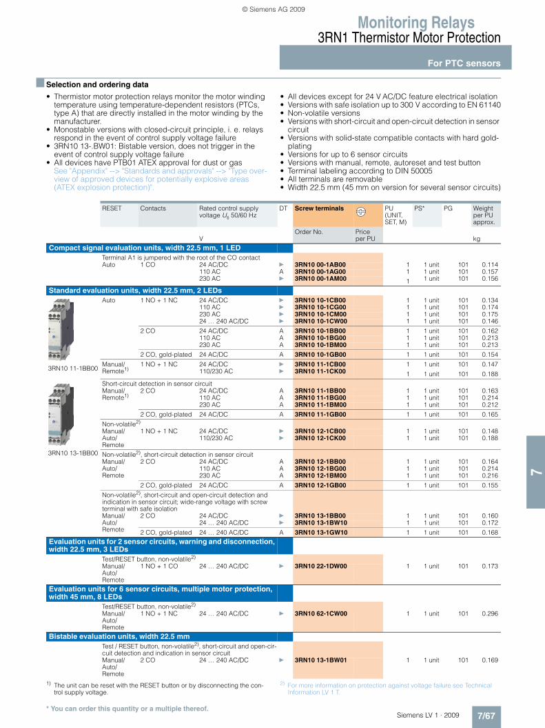
Monitoring Relays3RN1 Thermistor Motor Protection
For PTC sensors
7/67Siemens LV 1 · 2009
77
■ Selection and ordering data
• Thermistor motor protection relays monitor the motor winding temperature using temperature-dependent resistors (PTCs, type A) that are directly installed in the motor winding by the manufacturer.
• Monostable versions with closed-circuit principle, i. e. relays respond in the event of control supply voltage failure
• 3RN10 13-.BW01: Bistable version, does not trigger in the event of control supply voltage failure
• All devices have PTB01 ATEX approval for dust or gas See "Appendix" --> "Standards and approvals" --> "Type over-view of approved devices for potentially explosive areas (ATEX explosion protection)".
• All devices except for 24 V AC/DC feature electrical isolation• Versions with safe isolation up to 300 V according to EN 61140• Non-volatile versions• Versions with short-circuit and open-circuit detection in sensor
circuit• Versions with solid-state compatible contacts with hard gold-
plating• Versions for up to 6 sensor circuits• Versions with manual, remote, autoreset and test button• Terminal labeling according to DIN 50005• All terminals are removable• Width 22.5 mm (45 mm on version for several sensor circuits)
1) The unit can be reset with the RESET button or by disconnecting the con-trol supply voltage.
2) For more information on protection against voltage failure see Technical Information LV 1 T.
RESET Contacts Rated control supply voltage Us 50/60 Hz
DT Screw terminals PU (UNIT, SET, M)
PS* PG Weight per PU approx.
VOrder No. Price
per PU kgCompact signal evaluation units, width 22.5 mm, 1 LED
Terminal A1 is jumpered with the root of the CO contactAuto 1 CO 24 AC/DC } 3RN10 00-1AB00 1 1 unit 101 0.114
110 AC A 3RN10 00-1AG00 1 1 unit 101 0.157230 AC } 3RN10 00-1AM00 1 1 unit 101 0.156
Standard evaluation units, width 22.5 mm, 2 LEDs
3RN10 11-1BB00
3RN10 13-1BB00
Auto 1 NO + 1 NC 24 AC/DC } 3RN10 10-1CB00 1 1 unit 101 0.134110 AC } 3RN10 10-1CG00 1 1 unit 101 0.174230 AC } 3RN10 10-1CM00 1 1 unit 101 0.17524 … 240 AC/DC } 3RN10 10-1CW00 1 1 unit 101 0.146
2 CO 24 AC/DC A 3RN10 10-1BB00 1 1 unit 101 0.162110 AC A 3RN10 10-1BG00 1 1 unit 101 0.213230 AC A 3RN10 10-1BM00 1 1 unit 101 0.213
2 CO, gold-plated 24 AC/DC A 3RN10 10-1GB00 1 1 unit 101 0.154
Manual/ Remote1)
1 NO + 1 NC 24 AC/DC } 3RN10 11-1CB00 1 1 unit 101 0.147110/230 AC } 3RN10 11-1CK00 1 1 unit 101 0.188
Short-circuit detection in sensor circuitManual/ Remote1)
2 CO 24 AC/DC A 3RN10 11-1BB00 1 1 unit 101 0.163110 AC A 3RN10 11-1BG00 1 1 unit 101 0.214230 AC A 3RN10 11-1BM00 1 1 unit 101 0.212
2 CO, gold-plated 24 AC/DC A 3RN10 11-1GB00 1 1 unit 101 0.165
Non-volatile2)
Manual/ Auto/Remote
1 NO + 1 NC 24 AC/DC } 3RN10 12-1CB00 1 1 unit 101 0.148110/230 AC } 3RN10 12-1CK00 1 1 unit 101 0.188
Non-volatile2), short-circuit detection in sensor circuitManual/ Auto/Remote
2 CO 24 AC/DC A 3RN10 12-1BB00 1 1 unit 101 0.164110 AC A 3RN10 12-1BG00 1 1 unit 101 0.214230 AC A 3RN10 12-1BM00 1 1 unit 101 0.216
2 CO, gold-plated 24 AC/DC A 3RN10 12-1GB00 1 1 unit 101 0.155
Non-volatile2), short-circuit and open-circuit detection and indication in sensor circuit; wide-range voltage with screw terminal with safe isolationManual/ Auto/Remote
2 CO 24 AC/DC } 3RN10 13-1BB00 1 1 unit 101 0.16024 … 240 AC/DC } 3RN10 13-1BW10 1 1 unit 101 0.172
2 CO, gold-plated 24 … 240 AC/DC A 3RN10 13-1GW10 1 1 unit 101 0.168Evaluation units for 2 sensor circuits, warning and disconnection, width 22.5 mm, 3 LEDs
Test/RESET button, non-volatile2)
Manual/ Auto/Remote
1 NO + 1 CO 24 … 240 AC/DC } 3RN10 22-1DW00 1 1 unit 101 0.173
Evaluation units for 6 sensor circuits, multiple motor protection, width 45 mm, 8 LEDs
Test/RESET button, non-volatile2)
Manual/ Auto/Remote
1 NO + 1 NC 24 … 240 AC/DC } 3RN10 62-1CW00 1 1 unit 101 0.296
Bistable evaluation units, width 22.5 mmTest / RESET button, non-volatile2), short-circuit and open-cir-cuit detection and indication in sensor circuitManual/ Auto/Remote
2 CO 24 … 240 AC/DC } 3RN10 13-1BW01 1 1 unit 101 0.169
* You can order this quantity or a multiple thereof.
LV1_09_Gesamt_EN.book Seite 67 Mittwoch, 11. Februar 2009 3:54 15
© Siemens AG 2009

Monitoring Relays3RN1 Thermistor Motor Protection
For PTC sensors
7/68 Siemens LV 1 · 2009
7
• Thermistor motor protection relays monitor the motor winding temperature using temperature-dependent resistors (PTCs, type A) that are directly installed in the motor winding by the manufacturer.
• Monostable versions with closed-circuit principle, i. e. relays respond in the event of control supply voltage failure
• 3RN10 13-.BW01: Bistable version, does not trigger in the event of control supply voltage failure
• All devices have PTB01 ATEX approval for dust or gas See "Appendix" --> "Standards and approvals" --> "Type over-view of approved devices for potentially explosive areas (ATEX explosion protection)".
• All devices except for 24 V AC/DC feature electrical isolation• Versions with safe isolation up to 300 V according to EN 61140• Non-volatile versions• Versions with short-circuit and open-circuit detection in sensor
circuit• Versions with solid-state compatible contacts with hard gold-
plating• Versions for up to 6 sensor circuits• Versions with manual, remote, autoreset and test button• Terminal labeling according to DIN EN 50005• All terminals are removable• Width 22.5 mm (45 mm on version for several sensor circuits)
1) The unit can be reset with the RESET button or by disconnecting the con-trol supply voltage.
2) For more information on protection against voltage failure see Technical Information LV 1 T.
RESET Contacts Rated control supply volt-age Us 50/60 Hz
DT Spring-type terminals
PU (UNIT, SET, M)
PS* PG Weight per PU approx.
VOrder No. Price
per PU kgCompact signal evaluation units, width 22.5 mm, 1 LED
Terminal A1 is jumpered with the root of the changeover contactAuto 1 CO 24 AC/DC A 3RN10 00-2AB00 1 1 unit 101 0.104
110 AC B 3RN10 00-2AG00 1 1 unit 101 0.153230 AC B 3RN10 00-2AM00 1 1 unit 101 0.153
Standard evaluation units, width 22.5 mm, 2 LEDs
3RN10 12-2CK00
Auto 1 NO + 1 NC 24 AC/DC } 3RN10 10-2CB00 1 1 unit 101 0.116110 AC A 3RN10 10-2CG00 1 1 unit 101 0.153230 AC A 3RN10 10-2CM00 1 1 unit 101 0.15924 … 240 AC/DC A 3RN10 10-2CW00 1 1 unit 101 0.127
2 CO 24 AC/DC A 3RN10 10-2BB00 1 1 unit 101 0.137110 AC C 3RN10 10-2BG00 1 1 unit 101 0.139230 AC A 3RN10 10-2BM00 1 1 unit 101 0.190
2 CO, gold-plated 24 AC/DC C 3RN10 10-2GB00 1 1 unit 101 0.139
Manual/ Remote1)
1 NO + 1 NC 24 AC/DC A 3RN10 11-2CB00 1 1 unit 101 0.125110/230 AC A 3RN10 11-2CK00 1 1 unit 101 0.164
Short-circuit detection in sensor circuitManual/ Remote1)
2 CO 24 AC/DC A 3RN10 11-2BB00 1 1 unit 101 0.138110 AC C 3RN10 11-2BG00 1 1 unit 101 0.190230 AC A 3RN10 11-2BM00 1 1 unit 101 0.192
2 CO, gold-plated 24 AC/DC A 3RN10 11-2GB00 1 1 unit 101 0.154
Non-volatile2)
Manual/ Auto/Remote
1 NO + 1 NC 24 AC/DC A 3RN10 12-2CB00 1 1 unit 101 0.125110/230 AC A 3RN10 12-2CK00 1 1 unit 101 0.161
Non-volatile2), short-circuit detection in sensor circuitManual/ Auto/ Remote
2 CO 24 AC/DC C 3RN10 12-2BB00 1 1 unit 101 0.130110 AC C 3RN10 12-2BG00 1 1 unit 101 0.130230 AC C 3RN10 12-2BM00 1 1 unit 101 0.181
2 CO, gold-plated 24 AC/DC C 3RN10 12-2GB00 1 1 unit 101 0.140
Non-volatile2), short-circuit and open-circuit detection and indication in sensor circuitManual/ Auto/Remote
2 CO 24 AC/DC A 3RN10 13-2BB00 1 1 unit 101 0.14024 … 240 AC/DC A 3RN10 13-2BW00 1 1 unit 101 0.151
2 CO, gold-plated 24 … 240 AC/DC C 3RN10 13-2GW00 1 1 unit 101 0.143Evaluation units for 2 sensor circuits, warning and disconnection, width 22.5 mm, 3 LEDs
Test/RESET button, non-volatile2)
Manual/ Auto/Remote
1 NO + 1 CO 24 … 240 AC/DC A 3RN10 22-2DW00 1 1 unit 101 0.147
Evaluation units for 6 sensor circuits, multiple motor protection, width 45 mm, 8 LEDs
Test/RESET button, non-volatile2)
Manual/ Auto/Remote
1 NO + 1 NC 24 … 240 AC/DC A 3RN10 62-2CW00 1 1 unit 101 0.251
Bistable evaluation units, width 22.5 mmTest / RESET button, non-volatile2), short-circuit and open-circuit detection and indication in sensor circuitManual/ Auto/Remote
2 CO 24 … 240 AC/DC A 3RN10 13-2BW01 1 1 unit 101 0.139
* You can order this quantity or a multiple thereof.
LV1_09_Gesamt_EN.book Seite 68 Mittwoch, 11. Februar 2009 3:54 15
© Siemens AG 2009

Monitoring Relays3RN1 Thermistor Motor Protection
For PTC sensors
7/69Siemens LV 1 · 2009
77
■ Accessories
1) Computer labeling system for individual inscription of unit labeling plates available from: murrplastik Systemtechnik GmbH.http://www.murrplastik.com
Use Version DT Order No. Price per PU
PU (UNIT, SET, M)
PS* PG Weight per PU approx.
kgBlank labels
Blank labels, 20 mm x 7 mm, pastel turquoise1)
C 3RT19 00-1SB20 100 340 units 101 0.200
Push-in lugs
3RP19 03
For devices with 1 or 2 CO contacts
Push-in lugs For screw fixing,2 units are required for each device
} 3RP19 03 1 10 units 101 0.002
* You can order this quantity or a multiple thereof.
LV1_09_Gesamt_EN.book Seite 69 Mittwoch, 11. Februar 2009 3:54 15
© Siemens AG 2009

3TK28 Safety Relays
General data
7/70 Siemens LV 1 · 2009
7
■ Overview
SIRIUS safety relays are the key elements of a consistent and cost-effective safety chain. Be it EMERGENCY-STOP disconnec-tion, protective door monitoring or the protection of presses or punches – with SIRIUS safety relays every safety application can be implemented to optimum effect in terms of engineering and price.
SIRIUS safety relays provide numerous safety-related functions:• Monitoring the safety functions of sensors• Monitoring the sensor leads• Monitoring the correct operation of the safety relay• Monitoring the actuators (contactors) in the shutdown circuit• Safety-oriented disconnection when dangers arise
SIRIUS safety relays meet the highest requirements (Category 4) according to EN 954-1 and achieve the highest safety integrity level (SIL 3) according to IEC 61508.
■ Benefits
General• Can be used for all safety applications thanks to compliance
with the highest safety requirements (Category 4 according to EN 954-1 or SIL 3 according to IEC 61508)
• Suitable for use all over the world through compliance with all globally established certifications
• Compact, service-proven SIRIUS design creates more space in the control cabinet
• Flexible connectability and expendability make subsequent changes easy
• Removable terminals for greater plant availability• Yellow front plate clearly identifies the device as an item of
safety technology• Sensor cable up to 2000 m long enables use in large-scale
plants
Relay outputs• Different voltages can be switched through the floating
contacts• Higher currents can be switched with relay contacts
Solid-state outputs• Wear-free• Suitable for operation in fast switching applications• Insensitive to vibrations and dirt• Good electrical endurance
Microprocessor systems• Flexible use thanks to many different integrated functions• Easy parameterization using DIP switches on the front• High functional reliability based on extensive monitoring
functions• Operated by the machine control• Also connection of non-contact sensors (light arrays, light bar-
riers etc.)
■ Application
SIRIUS safety relays are used mainly in autonomous safety ap-plications which are not connected to a safety-oriented bus sys-tem. Their function here is to evaluate the sensors and the safety-oriented shutdown of hazards. Also they check and monitor the sensors, actuators and safety-oriented functions of the safety relay.
LV1_09_Gesamt_EN.book Seite 70 Mittwoch, 11. Februar 2009 3:54 15
© Siemens AG 2009

3TK28 Safety Relays
With electronic enabling circuits
7/71Siemens LV 1 · 2009
77
■ Selection and ordering data
✔ = Available-- = Not available
1) The outputs are only safe when an external contactor is used.
Type 3TK28 40 3TK28 41 3TK28 42 3TK28 45
Basic units Basic units Basic units Multi-function units "automatic and monitored start"
Multi-function units "automatic and monitored start"
Multi-function units "monitored start"
Multi-function units "monitored start"
Multi-function units OK button
Multi-function units OK button
Multi-function units "spring-type inter-locking"
Multi-function units "solenoid inter-locking"
tv tv tv tv tv tvSensors
• Input 1 1 1 2 2 2 2 2 2 2 2
• Solid-state -- ✔ ✔ ✔ ✔ ✔ ✔ ✔ ✔ ✔ ✔
• With contacts ✔ ✔ ✔ ✔ ✔ ✔ ✔ ✔ ✔ ✔ ✔
Safety mats -- ✔ ✔ ✔ ✔ ✔ ✔ -- -- -- --
Start
• Auto ✔ ✔ ✔ 1 1 -- -- 1 1 -- --
• Monitored ✔ ✔ ✔ 1 1 2 2 1 1 2 2
Cascading input 24 V DC -- ✔ ✔ ✔ ✔ ✔ ✔ ✔ ✔ ✔ ✔
Key-operated switches -- -- -- ✔ ✔ ✔ ✔ ✔ ✔ ✔ ✔
Enabling circuit, floating
• Stop category 0 -- -- -- 2 NO 1 NO 2 NO 1 NO 2 NO 1 NO 1 NO 1 NO
• Stop category 1 -- -- -- -- 1 NO -- 1 NO -- 1 NO 1 NO 1 NO
Enabling circuit, solid-state
• Stop category 0 21) 2 1 2 1 2 1 2 1 1 1
• Stop category 1 -- -- 1 -- 1 -- 1 -- 1 1 1
Signaling outputs
• Floating -- -- -- -- -- -- -- -- -- -- --
• Solid-state -- -- -- 1 1 1 1 1 1 1 1
Category acc. to EN 954-1 max 3 4 4 4 4 4 4 4 4 4 4
SIL level max.acc. to IEC 61508 2 3 3 3 3 3 3 3 3 3 3
Performance level PLacc. to ISO 13849-1 -- -- -- e e e e e e e e
Rated control supply voltage24 V DC
✔ ✔ ✔ ✔ ✔ ✔ ✔ ✔ ✔ ✔ ✔
LV1_09_Gesamt_EN.book Seite 71 Mittwoch, 11. Februar 2009 3:54 15
© Siemens AG 2009

3TK28 Safety Relays
With electronic enabling circuits
7/72 Siemens LV 1 · 2009
7
Rated control supply voltage Us
OFF-delaytv
DT Screw terminals PU (UNIT, SET, M)
PS* PG Weight per PU approx.
V sOrder No. Price
per PU kg
Rated control supply voltage Us 24 V DC
3TK28 41-1BB40
3TK28 42-1BB41
3TK28 45-1HB40
3TK28 45-1HB41
3TK28 45-1DB40
3TK28 45-1DB41
3TK28 40 basic units
24 DC -- A 3TK28 40-1BB40 1 1 unit 102 0.180
3TK28 41 basic units
24 DC -- A 3TK28 41-1BB40 1 1 unit 102 0.166
3TK28 42 basic units tv24 DC 0.05 ... 3 A 3TK28 42-1BB41 1 1 unit 102 0.168
0.5 ... 30 A 3TK28 42-1BB42 1 1 unit 102 0.1665 ... 300 A 3TK28 42-1BB44 1 1 unit 102 0.166
3TK28 45 multi-function units "automatic and monitored start"
24 DC -- A 3TK28 45-1HB40 1 1 unit 102 0.350
3TK28 45 multi-function units tv"automatic and monitored start"
24 DC 0.05 ... 3 A 3TK28 45-1HB41 1 1 unit 102 0.3500.5 ... 30 A 3TK28 45-1HB42 1 1 unit 102 0.3505 ... 300 A 3TK28 45-1HB44 1 1 unit 102 0.350
3TK28 45 multi-function units "monitored start"
24 DC -- A 3TK28 45-1DB40 1 1 unit 102 0.350
3TK28 45 multi-function units tv"monitored start"
24 DC 0.05 ... 3 A 3TK28 45-1DB41 1 1 unit 102 0.3500.5 ... 30 A 3TK28 45-1DB42 1 1 unit 102 0.3505 ... 300 A 3TK28 45-1DB44 1 1 unit 102 0.350
3TK28 45 multi-function units "OK button"
24 DC -- A 3TK28 45-1EB40 1 1 unit 102 0.350
3TK28 45 multi-function units tv"OK button"
24 DC 0.05 ... 3 A 3TK28 45-1EB41 1 1 unit 102 0.3500.5 ... 30 A 3TK28 45-1EB42 1 1 unit 102 0.3505 ... 300 A 3TK28 45-1EB44 1 1 unit 102 0.350
3TK28 45 multi-function units tv"spring-type interlocking"
24 DC 0.05 ... 3 A 3TK28 45-1FB41 1 1 unit 102 0.3500.5 ... 30 A 3TK28 45-1FB42 1 1 unit 102 0.3505 ... 300 A 3TK28 45-1FB44 1 1 unit 102 0.350
3TK28 45 multi-function units tv"solenoid interlocking"
24 DC 0.05 ... 3 A 3TK28 45-1GB41 1 1 unit 102 0.3500.5 ... 30 A 3TK28 45-1GB42 1 1 unit 102 0.3505 ... 300 A 3TK28 45-1GB44 1 1 unit 102 0.350
* You can order this quantity or a multiple thereof.
LV1_09_Gesamt_EN.book Seite 72 Mittwoch, 11. Februar 2009 3:54 15
© Siemens AG 2009

3TK28 Safety Relays
With electronic enabling circuits
7/73Siemens LV 1 · 2009
77
Rated control supply voltage Us
OFF-delaytv
DT Spring-type terminals
PU (UNIT, SET, M)
PS* PG Weight per PU approx.
V sOrder No. Price
per PU kg
Rated control supply voltage Us 24 V DC
3TK28 45-2DB40
3TK28 45-2DB41
3TK28 40 basic units
24 DC -- B 3TK28 40-2BB40 1 1 unit 102 0.150
3TK28 41 basic units
24 DC -- A 3TK28 41-2BB40 1 1 unit 102 0.143
3TK28 42 basic units tv24 DC 0.05 ... 3 B 3TK28 42-2BB41 1 1 unit 102 0.143
0.5 ... 30 A 3TK28 42-2BB42 1 1 unit 102 0.1465 ... 300 B 3TK28 42-2BB44 1 1 unit 102 0.149
3TK28 45 multi-function units "automatic and monitored start"
24 DC -- B 3TK28 45-2HB40 1 1 unit 102 0.350
3TK28 45 multi-function units tv"automatic and monitored start"
24 DC 0.05 ... 3 B 3TK28 45-2HB41 1 1 unit 102 0.3500.5 ... 30 B 3TK28 45-2HB42 1 1 unit 102 0.3505 ... 300 B 3TK28 45-2HB44 1 1 unit 102 0.350
3TK28 45 multi-function units "monitored start"
24 DC -- B 3TK28 45-2DB40 1 1 unit 102 0.350
3TK28 45 multi-function units tv"monitored start"
24 DC 0.05 ... 3 B 3TK28 45-2DB41 1 1 unit 102 0.3500.5 ... 30 B 3TK28 45-2DB42 1 1 unit 102 0.3505 ... 300 B 3TK28 45-2DB44 1 1 unit 102 0.350
3TK28 45 multi-function units "OK button"
24 DC -- B 3TK28 45-2EB40 1 1 unit 102 0.350
3TK28 45 multi-function units tv"OK button"
24 DC 0.05 ... 3 B 3TK28 45-2EB41 1 1 unit 102 0.3500.5 ... 30 B 3TK28 45-2EB42 1 1 unit 102 0.3505 ... 300 B 3TK28 45-2EB44 1 1 unit 102 0.350
3TK28 45 multi-function units tv"spring-type interlocking"
24 DC 0.05 ... 3 B 3TK28 45-2FB41 1 1 unit 102 0.3500.5 ... 30 B 3TK28 45-2FB42 1 1 unit 102 0.3505 ... 300 B 3TK28 45-2FB44 1 1 unit 102 0.350
3TK28 45 multi-function units tv"solenoid interlocking"
24 DC 0.05 ... 3 B 3TK28 45-2GB41 1 1 unit 102 0.3500.5 ... 30 B 3TK28 45-2GB42 1 1 unit 102 0.3505 ... 300 B 3TK28 45-2GB44 1 1 unit 102 0.350
* You can order this quantity or a multiple thereof.
LV1_09_Gesamt_EN.book Seite 73 Mittwoch, 11. Februar 2009 3:54 15
© Siemens AG 2009

3TK28 Safety Relays
With electronic enabling circuits
7/74 Siemens LV 1 · 2009
7
■ Accessories
Version DT Order No. Price per PU
PU (UNIT, SET, M)
PS* PG Weight per PU approx.
kgPush-in lugs and covers
3RP19 03
Push-in lugsFor screw fixing,2 units are required for each device
} 3RP19 03 1 10 units 101 0.002
3RP19 02
Sealable covers For securing against unauthorized adjustment of setting knobs
} 3RP19 02 1 5 units 101 0.004
Screwdrivers
8WA2 803
ScrewdriversWith screwdriver blades 3.5 mm x 0.5 mm
Long, green C 8WA2 803 1 1 unit 041 0.024
Long, green, partially insulated C 8WA2 880 1 1 unit 041 0.034
* You can order this quantity or a multiple thereof.
LV1_09_Gesamt_EN.book Seite 74 Mittwoch, 11. Februar 2009 3:54 15
© Siemens AG 2009

3TK28 Safety Relays
With relay enabling circuits
7/75Siemens LV 1 · 2009
77
■ Selection and ordering data
✔ = Available-- = Not available
1) The ON button is not monitored.2) Depending on the hazard assessment, additional measures may be nec-
essary in the sensor circuit (e. g. protected laying).
Type 3TK28 21 3TK28 22 3TK28 23 3TK28 24 3TK28 25 3TK28 26
Basic units Basic units Basic units Basic units Basic units Basic units 24 V DC
Basic units Wide voltage range
Sensors
• Input 1 1 1 1 1 1 1
• Solid-state -- -- -- -- -- ✔ ✔
• With contacts ✔ ✔1) ✔ ✔ ✔ ✔ ✔
Safety mats -- -- -- -- -- ✔ ✔
Start
• Auto ✔ ✔ -- ✔ ✔ ✔ ✔
• Monitored -- -- ✔ -- ✔ ✔ ✔
Cascading input 24 V DC -- -- -- -- -- ✔ ✔
Key-operated switches -- -- -- -- -- -- --
Enabling circuit, floating
• Stop category 0 3 NO 2 NO 2 NO 2 NO 3 NO 4 NO 4 NO
• Stop category 1 -- -- -- -- -- -- --
Enabling circuit, solid-state
• Stop category 0 -- -- -- -- -- -- --
• Stop category 1 -- -- -- -- -- -- --
Signaling outputs
• Floating 1 NC -- -- -- 2 NC 1 NC 1 NO + 1 NC
• Solid-state -- -- -- -- -- 2 --
Category acc. to EN 954-1 max 32) 4 4 32) 4 4 4
SIL level max.acc. to IEC 61508 2 -- -- 2 3 3 3
Performance level PLacc. to ISO 13849-1 -- -- -- -- -- e e
Rated control supply voltage
• 24 V DC -- -- -- ✔ ✔ ✔ --
• 24 V AC/DC ✔ ✔ ✔ ✔ -- -- --
• 24 V AC -- -- -- -- ✔ -- --
• 115 V AC -- -- -- ✔ ✔ -- --
• 230 V AC -- -- -- ✔ ✔ -- --
• 24 ... 240 V AC/DC -- -- -- -- -- -- ✔
LV1_09_Gesamt_EN.book Seite 75 Mittwoch, 11. Februar 2009 3:54 15
© Siemens AG 2009

3TK28 Safety Relays
With relay enabling circuits
7/76 Siemens LV 1 · 2009
7
n
✔ = Available-- = Not available
1) Only possible for instantaneous enabling contacts, otherwise Category 3.2) For expansion of Siemens safety products.3) Only possible for instantaneous enabling contacts, otherwise Category 2.
Type 3TK28 26 3TK28 27 3TK28 28 3TK28 30 3TK28 34 3TK28 35
Basic units 24 V DC
Basic units Wide voltage range
Basic units Basic units Expansion units2) Two-hand control devices
Slowing down test devices
tv tv tv tvSensors
• Input 1 1 1 1 -- 1 --
• Solid-state ✔ ✔ -- -- -- -- --
• With contacts ✔ ✔ ✔ ✔ -- ✔ --
Safety mats ✔ ✔ -- -- -- -- --
Start
• Auto ✔ ✔ -- ✔ -- -- --
• Monitored ✔ ✔ ✔ -- -- -- --
Cascading input 24 V DC ✔ ✔ -- -- -- -- --
Key-operated switches -- -- -- -- -- -- --
Enabling circuit, floating
• Stop category 0 2 NO 2 NO 2 NO 2 NO 4 NO 2 NO+2 NC 3 NO+2 NC
• Stop category 1 2 NO 2 NO 2 NO 2 NO -- -- --
Enabling circuit, solid-state
• Stop category 0 -- -- -- -- -- -- --
• Stop category 1 -- -- -- -- -- -- --
Signaling outputs
• Floating 2 NC 1 NO + 2 NC 1 NC 1 NC -- 2 --
• Solid-state 2 -- -- -- -- -- --
Category acc. to EN 954-1 max 4 4 41) 41) As basic unit 4 4
SIL level max.acc. to IEC 61508 3 3 33) 33) As basic unit -- 3
Performance level PLacc. to ISO 13849-1 e e -- -- -- -- --
Rated control supply voltage
• 24 V DC ✔ -- ✔ ✔ -- ✔ ✔
• 24 V AC/DC -- -- -- -- ✔ -- --
• 24 V AC -- -- ✔ ✔ -- ✔ ✔
• 115 V AC -- -- ✔ ✔ ✔ ✔ ✔
• 230 V AC -- -- ✔ ✔ ✔ ✔ ✔
• 24 ... 240 V AC/DC -- ✔ -- -- -- -- --
LV1_09_Gesamt_EN.book Seite 76 Mittwoch, 11. Februar 2009 3:54 15
© Siemens AG 2009

3TK28 Safety Relays
With relay enabling circuits
7/77Siemens LV 1 · 2009
77
■ Selection and ordering data
Rated control supply voltage Us
OFF-delaytv
DT Screw terminals PU (UNIT, SET, M)
PS* PG Weight per PU approx.
V sOrder No. Price
per PU kg
Rated control supply voltages Us 24 V DC and 50/60 Hz, 24, 115, 230 V AC
3TK28 21-1CB30
3TK28 25-1BB40
3TK28 26-1BB40
3TK28 27-1BB41
3TK28 30-1CB30
3TK28 21 basic units
24 AC/DC -- } 3TK28 21-1CB30 1 1 unit 102 0.276
3TK28 22 basic units
24 AC/DC -- } 3TK28 22-1CB30 1 1 unit 102 0.271
3TK28 23 basic units
24 AC/DC -- } 3TK28 23-1CB30 1 1 unit 102 0.271
3TK28 24 basic units
24 AC/DC -- } 3TK28 24-1CB30 1 1 unit 102 0.25424 DC -- } 3TK28 24-1BB40 1 1 unit 102 0.249115 AC -- A 3TK28 24-1AJ20 1 1 unit 102 0.294230 AC -- } 3TK28 24-1AL20 1 1 unit 102 0.288
3TK28 25 basic units
24 DC -- } 3TK28 25-1BB40 1 1 unit 102 0.42324 AC -- A 3TK28 25-1AB20 1 1 unit 102 0.421115 AC -- } 3TK28 25-1AJ20 1 1 unit 102 0.519230 AC -- } 3TK28 25-1AL20 1 1 unit 102 0.516
3TK28 26 basic units
24 DC -- } 3TK28 26-1BB40 1 1 unit 102 0.37024 ... 240 AC/DC -- } 3TK28 26-1CW30 1 1 unit 102 0.400
3TK28 26 basic units tv24 DC 0.05 ... 3 A 3TK28 26-1BB41 1 1 unit 102 0.37024 ... 240 AC/DC A 3TK28 26-1CW31 1 1 unit 102 0.400
24 DC 0.5 ... 30 A 3TK28 26-1BB42 1 1 unit 102 0.37024 ... 240 AC/DC A 3TK28 26-1CW32 1 1 unit 102 0.400
24 DC 5 ... 300 A 3TK28 26-1BB44 1 1 unit 102 0.37024 ... 240 AC/DC A 3TK28 26-1CW34 1 1 unit 102 0.400
3TK28 27 basic units tv24 DC 0.05 ... 3 } 3TK28 27-1BB41 1 1 unit 102 0.49524 AC B 3TK28 27-1AB21 1 1 unit 102 0.499115 AC B 3TK28 27-1AJ21 1 1 unit 102 0.650230 AC A 3TK28 27-1AL21 1 1 unit 102 0.650
24 DC 0.5 ... 30 } 3TK28 27-1BB40 1 1 unit 102 0.49724 AC A 3TK28 27-1AB20 1 1 unit 102 0.496115 AC } 3TK28 27-1AJ20 1 1 unit 102 0.650230 AC } 3TK28 27-1AL20 1 1 unit 102 0.650
3TK28 28 basic units tv24 DC24 AC115 AC
0.05 ... 3 } 3TK28 28-1BB41 1 1 unit 102 0.499B 3TK28 28-1AB21 1 1 unit 102 0.501B 3TK28 28-1AJ21 1 1 unit 102 0.657
230 AC A 3TK28 28-1AL21 1 1 unit 102 0.650
24 DC24 AC115 AC
0.5 ... 30 } 3TK28 28-1BB40 1 1 unit 102 0.496B 3TK28 28-1AB20 1 1 unit 102 0.500A 3TK28 28-1AJ20 1 1 unit 102 0.650
230 AC A 3TK28 28-1AL20 1 1 unit 102 0.650
3TK28 30 expansion units
24 AC/DC -- } 3TK28 30-1CB30 1 1 unit 102 0.267115 AC A 3TK28 30-1AJ20 1 1 unit 102 0.306230 AC A 3TK28 30-1AL20 1 1 unit 102 0.306
3TK28 34 two-hand control devices
24 DC -- } 3TK28 34-1BB40 1 1 unit 102 0.43224 AC A 3TK28 34-1AB20 1 1 unit 102 0.424115 AC A 3TK28 34-1AJ20 1 1 unit 102 0.519230 AC A 3TK28 34-1AL20 1 1 unit 102 0.519
3TK28 35 slowing down monitoring devices
24 DC -- B 3TK28 35-1BB40 1 1 unit 102 0.495115 AC -- B 3TK28 35-1AJ20 1 1 unit 102 0.572230 AC -- B 3TK28 35-1AL20 1 1 unit 102 0.574
* You can order this quantity or a multiple thereof.
LV1_09_Gesamt_EN.book Seite 77 Mittwoch, 11. Februar 2009 3:54 15
© Siemens AG 2009

3TK28 Safety Relays
With relay enabling circuits
7/78 Siemens LV 1 · 2009
7
Rated control supply voltage Us
OFF-delaytv
DT Spring-type terminals
PU (UNIT, SET, M)
PS* PG Weight per PU approx.
V sOrder No. Price
per PU kg
Rated control supply voltages Us 24 V DC and 50/60 Hz, 24, 115, 230 V AC
3TK28 26-2BB40
3TK28 21 basic units
24 AC/DC -- } 3TK28 21-2CB30 1 1 unit 102 0.246
3TK28 22 basic units
24 AC/DC -- A 3TK28 22-2CB30 1 1 unit 102 0.250
3TK28 23 basic units
24 AC/DC -- A 3TK28 23-2CB30 1 1 unit 102 0.247
3TK28 24 basic units
24 AC/DC -- A 3TK28 24-2CB30 1 1 unit 102 0.23024 DC -- } 3TK28 24-2BB40 1 1 unit 102 0.228115 AC -- B 3TK28 24-2AJ20 1 1 unit 102 0.265230 AC -- B 3TK28 24-2AL20 1 1 unit 102 0.270
3TK28 25 basic units
24 DC -- } 3TK28 25-2BB40 1 1 unit 102 0.37424 AC -- B 3TK28 25-2AB20 1 1 unit 102 0.375115 AC -- B 3TK28 25-2AJ20 1 1 unit 102 0.472230 AC -- B 3TK28 25-2AL20 1 1 unit 102 0.475
3TK28 26 basic units
24 DC -- A 3TK28 26-2BB40 1 1 unit 102 0.37024 ... 240 AC/DC -- A 3TK28 26-2CW30 1 1 unit 102 0.400
3TK28 26 basic units tv24 DC 0.05 ... 3 A 3TK28 26-2BB41 1 1 unit 102 0.37024 ... 240 AC/DC A 3TK28 26-2CW31 1 1 unit 102 0.400
24 DC 0.5 ... 30 A 3TK28 26-2BB42 1 1 unit 102 0.37024 ... 240 AC/DC A 3TK28 26-2CW32 1 1 unit 102 0.400
24 DC 5 ... 300 A 3TK28 26-2BB44 1 1 unit 102 0.37024 ... 240 AC/DC A 3TK28 26-2CW34 1 1 unit 102 0.400
3TK28 27 basic units tv24 DC 0.05 ... 3 A 3TK28 27-2BB41 1 1 unit 102 0.45424 AC B 3TK28 27-2AB21 1 1 unit 102 0.454115 AC B 3TK28 27-2AJ21 1 1 unit 102 0.240230 AC B 3TK28 27-2AL21 1 1 unit 102 0.605
24 DC 0.5 ... 30 A 3TK28 27-2BB40 1 1 unit 102 0.45524 AC B 3TK28 27-2AB20 1 1 unit 102 0.454115 AC B 3TK28 27-2AJ20 1 1 unit 102 0.606230 AC B 3TK28 27-2AL20 1 1 unit 102 0.604
3TK28 28 basic units tv24 DC24 AC115 AC
0.05 ... 3 A 3TK28 28-2BB41 1 1 unit 102 0.450C 3TK28 28-2AB21 1 1 unit 102 0.454B 3TK28 28-2AJ21 1 1 unit 102 0.240
230 AC B 3TK28 28-2AL21 1 1 unit 102 0.608
24 DC24 AC115 AC
0.5 ... 30 } 3TK28 28-2BB40 1 1 unit 102 0.457B 3TK28 28-2AB20 1 1 unit 102 0.468B 3TK28 28-2AJ20 1 1 unit 102 0.609
230 AC B 3TK28 28-2AL20 1 1 unit 102 0.612
3TK28 30 expansion units
24 AC/DC -- } 3TK28 30-2CB30 1 1 unit 102 0.244115 AC B 3TK28 30-2AJ20 1 1 unit 102 0.276230 AC B 3TK28 30-2AL20 1 1 unit 102 0.276
3TK28 34 two-hand control devices
24 DC -- A 3TK28 34-2BB40 1 1 unit 102 0.38324 AC B 3TK28 34-2AB20 1 1 unit 102 0.376115 AC B 3TK28 34-2AJ20 1 1 unit 102 0.472230 AC B 3TK28 34-2AL20 1 1 unit 102 0.472
3TK28 35 slowing down monitoring devices115 AC -- B 3TK28 35-2AJ20 1 1 unit 102 0.551230 AC -- B 3TK28 35-2AL20 1 1 unit 102 0.552
* You can order this quantity or a multiple thereof.
LV1_09_Gesamt_EN.book Seite 78 Mittwoch, 11. Februar 2009 3:54 15
© Siemens AG 2009

3TK28 Safety Relays
With relay enabling circuits
7/79Siemens LV 1 · 2009
77
■ Accessories
Version DT Order No. Price per PU
PU (UNIT, SET, M)
PS* PG Weight per PU approx.
kgPush-in lugs and covers
3RP19 03
Push-in lugsFor screw fixing,2 units are required for each device
} 3RP19 03 1 10 units 101 0,002
3RP19 02
Sealable covers For securing against unauthorized adjustment of set-ting knobs
• For 3TK28 21 to 3TK28 25, 3TK28 27, 3TK28 28, 3TK28 3.
} 3RP19 02 1 5 units 101 0,004
• For 3TK28 26 B 3TK28 26-0DA00-0HA0 1 5 units 102 0,004Screwdrivers
8WA2 803
ScrewdriversWith screwdriver blades 3.5 mm x 0.5 mm
Long, green C 8WA2 803 1 1 unit 041 0,024
Long, green, partially insulated C 8WA2 880 1 1 unit 041 0,034
* You can order this quantity or a multiple thereof.
LV1_09_Gesamt_EN.book Seite 79 Mittwoch, 11. Februar 2009 3:54 15
© Siemens AG 2009

3TK28 Safety Relays
With contactor relay enabling circuits
7/80 Siemens LV 1 · 2009
7
■ Selection and ordering data
✔ = Available-- = Not available
1) For expansion of Siemens safety products.
Type 3TK28 50 3TK28 51 3TK28 52 3TK28 53 3TK28 56 3TK28 57
Basic units Basic units Basic units Basic units Expansion units1) Expansion units1)
tvSensors• Input 1 1 1 1 -- --
• Solid-state -- -- -- ✔ -- --
• With contacts ✔ ✔ ✔ ✔ -- --
Safety mats ✔ ✔ ✔ ✔ -- --
Start• Auto ✔ ✔ ✔ ✔ -- --
• Monitored ✔ ✔ ✔ ✔ -- --
Cascading input 24 V DC -- -- -- ✔ ✔ ✔
Key-operated switches -- -- -- -- -- --
Enabling circuit, floating
• Stop category 0 3 NO 2 NO 6 NO 3 NO 6 NO --
• Stop category 1 -- -- -- -- -- 3 NO
Enabling circuit, solid-state
• Stop category 0 -- -- -- 1 1 1
• Stop category 1 -- -- -- -- -- --
Signaling outputs
• Floating -- 1 NC 1 NC -- 1 NC --
• Solid-state -- -- -- -- -- --
Category acc. to EN 954-1 max 3 3 3 4
Corresponds to basic unit
Corresponds to basic unit
SIL level max.acc. to IEC 61508 2 2 2 -- -- --
Performance level PLacc. to ISO 3849-1 -- -- -- -- -- --
Rated control supply voltage
• 24 V DC ✔ ✔ ✔ ✔ ✔ ✔
• 24 V AC/DC -- -- -- -- -- --
• 24 V AC ✔ ✔ -- -- -- --
• 115 V AC ✔ ✔ -- -- -- --
• 230 V AC ✔ ✔ ✔ -- -- --
• 24 ... 240 V AC/DC -- -- -- -- -- --
Rated operational voltage
• 24 V DC ✔ ✔ ✔ ✔ ✔ ✔
• 230 V AC ✔ ✔ ✔ ✔ ✔ ✔
• 600 V AC ✔ ✔ ✔ ✔ ✔ ✔
Switching capacity
• AC-15 at U = 230 V ✔ ✔ ✔ ✔ ✔ ✔
• DC-13 at U = 24 V ✔ ✔ ✔ ✔ ✔ ✔
LV1_09_Gesamt_EN.book Seite 80 Mittwoch, 11. Februar 2009 3:54 15
© Siemens AG 2009

3TK28 Safety Relays
With contactor relay enabling circuits
7/81Siemens LV 1 · 2009
77
■ Accessories
Rated control supply voltage Us
OFF-delaytv
DT Screw terminals PU (UNIT, SET, M)
PS* PG Weight per PU approx.
V sOrder No. Price
per PU kgRated control supply voltages Us24 V DC and 50/60 Hz, 115, 230 V AC
3TK28 50 basic units
24 DC -- A 3TK28 50-1BB40 1 1 unit 102 0.819115 AC B 3TK28 50-1AJ20 1 1 unit 102 0.765230 AC B 3TK28 50-1AL20 1 1 unit 102 0.770
3TK28 51 basic units
24 DC -- B 3TK28 51-1BB40 1 1 unit 102 0.821115 AC B 3TK28 51-1AJ20 1 1 unit 102 0.770230 AC B 3TK28 51-1AL20 1 1 unit 102 0.767
3TK28 52 basic units
24 DC -- A 3TK28 52-1BB40 1 1 unit 102 0.919230 AC B 3TK28 52-1AL20 1 1 unit 102 0.870
3TK28 53 basic units
24 DC -- A 3TK28 53-1BB40 1 1 unit 102 0.714
3TK28 56 expansion units
24 DC -- B 3TK28 56-1BB40 1 1 unit 102 0.785
3TK28 57 expansion units tv24 DC 0.05 ... 3 A 3TK28 57-1BB41 1 1 unit 102 0.68224 DC 0.5 ... 30 B 3TK28 57-1BB42 1 1 unit 102 0.67924 DC 5 ... 300 B 3TK28 57-1BB44 1 1 unit 102 0.684
Rated control supply voltage Us
OFF-delaytv
DT Spring-type terminals
PU (UNIT, SET, M)
PS* PG Weight per PU approx.
V sOrder No. Price
per PU kg
Rated control supply voltages Us24 V DC and 50/60 Hz, 115, 230 V AC
3TK28 50-2BB40
3TK28 51-2BB40
3TK28 52-2BB40
3TK28 50 basic units
24 DC -- B 3TK28 50-2BB40 1 1 unit 102 0.820115 AC B 3TK28 50-2AJ20 1 1 unit 102 0.650230 AC B 3TK28 50-2AL20 1 1 unit 102 0.761
3TK28 51 basic units
24 DC -- B 3TK28 51-2BB40 1 1 unit 102 0.650115 AC B 3TK28 51-2AJ20 1 1 unit 102 0.650230 AC B 3TK28 51-2AL20 1 1 unit 102 0.768
3TK28 52 basic units
24 DC -- B 3TK28 52-2BB40 1 1 unit 102 0.935230 AC B 3TK28 52-2AL20 1 1 unit 102 0.878
3TK28 53 basic units
24 DC -- B 3TK28 53-2BB40 1 1 unit 102 0.705
3TK28 56 expansion units
24 DC -- B 3TK28 56-2BB40 1 1 unit 102 0.750
3TK28 57 expansion units tv24 DC 0.05 ... 3 B 3TK28 57-2BB41 1 1 unit 102 0.650
0.5 ... 30 B 3TK28 57-2BB42 1 1 unit 102 0.6775 ... 300 B 3TK28 57-2BB44 1 1 unit 102 0.684
Version DT Order No. Price per PU
PU (UNIT, SET, M)
PS* PG Weight per PU approx.
kg
Screwdrivers
8WA2 803
ScrewdriversWith screwdriver blades 3.5 mm x 0.5 mm
Long, green C 8WA2 803 1 1 unit 041 0,024
Long, green, partially insulated C 8WA2 880 1 1 unit 041 0,034
* You can order this quantity or a multiple thereof.
LV1_09_Gesamt_EN.book Seite 81 Mittwoch, 11. Februar 2009 3:54 15
© Siemens AG 2009

3TK28 Safety Relays
With special functions
7/82 Siemens LV 1 · 2009
7
■ Selection and ordering data
✔ = Available-- = Not available
Type 3TK28 10
Standstill monitors
Sensors• Inputs 3
• Solid-state --
• With contacts --
• Without sensors (mea-suring inputs)
3
Safety mats --
Start• Auto ✔
• Monitored --
Cascading input 24 V DC --
Key-operated switches --
Enabling circuit, floating
• Stop category 0 3 NO + 1 NC
• Stop category 1 --
Enabling circuit, solid-state
• Stop category 0 --
• Stop category 1 --
Signaling outputs
• Floating 1 CO
• Solid-state 2
Category acc. to EN 954-1 max 4
SIL level max.acc. to IEC 61508 3
Performance level PLacc. to ISO 13849-1 e
Rated control supply voltage
• 24 V DC ✔
• 230 V AC ✔
• 400 V AC ✔
LV1_09_Gesamt_EN.book Seite 82 Mittwoch, 11. Februar 2009 3:54 15
© Siemens AG 2009

3TK28 Safety Relays
With special functions
7/83Siemens LV 1 · 2009
77
■ Accessories
Rated control supply voltage Us
OFF-delaytv
DT Screw terminals PU (UNIT, SET, M)
PS* PG Weight per PU approx.
V sOrder No. Price
per PU kg
Rated control supply voltages Us 24 V DC and 50/60 Hz, 230, 400 V AC
3TK28 10-0BA01
3TK28 10 standstill monitors
24 DC 0.2 ... 6 A 3TK28 10-0BA01 1 1 unit 102 0.500230 AC A 3TK28 10-0GA01 1 1 unit 102 0.500400 AC A 3TK28 10-0JA01 1 1 unit 102 0.500
Rated control supply voltage Us
OFF-delaytv
DT Spring-type terminals
PU (UNIT, SET, M)
PS* PG Weight per PU approx.
V sOrder No. Price
per PU kg
Rated control supply voltages Us 24 V DC and 50/60 Hz, 230, 400 V AC
3TK28 10-0GA02
3TK28 10 standstill monitors
24 DC 0.2 ... 6 A 3TK28 10-0BA02 1 1 unit 102 0.500230 AC A 3TK28 10-0GA02 1 1 unit 102 0.500400 AC A 3TK28 10-0JA02 1 1 unit 102 0.500
Version DT Order No. Price per PU
PU (UNIT, SET, M)
PS* PG Weight per PU approx.
kgPush-in lugs
3RP19 03
Push-in lugsFor screw fixing,2 units are required for each device
} 3RP19 03 1 10 units 101 0.002
Screwdrivers
8WA2 803
ScrewdriversWith screwdriver blades 3.5 mm x 0.5 mm
Long, green C 8WA2 803 1 1 unit 041 0.024
Long, green, partially insulated C 8WA2 880 1 1 unit 041 0.034
* You can order this quantity or a multiple thereof.
LV1_09_Gesamt_EN.book Seite 83 Mittwoch, 11. Februar 2009 3:54 15
© Siemens AG 2009

3RK3 Modular Safety System
General data
7/84 Siemens LV 1 · 2009
7
■ Overview
The 3RK3 modular safety system (MSS) is a freely parameteriz-able modular safety relay. Depending on the type of external connection, safety-orientated applications up to Category 4 ac-cording to EN 954-1, Performance Level e according to ISO 13849-1 and SIL3 according to IEC 62061 can be realized.
The modular safety relay permits several safety applications to be interconnected. The safety functions are easily created on the PC using a graphic parameterizing tool. For example, discon-nection ranges can be set and other dependencies defined.
With additional safety-oriented expansion modules the system is flexibly adapted to the required safety applications.
The MSS comprises the following system components:• Central module• Expansion modules• Interface module• Parameterization software• Accessories
The comprehensive error and status diagnostics provides the possibility of finding errors in the system and localizing signals from sensors. Plant downtimes can be reduced as the result.
Optional interface modules send the diagnostics data to higher-level bus systems (e. g. PROFIBUS DP). These data are then available for further processing in the automation system.
■ Benefits
• More functionality and flexibility through freely configurable safety logic
• For all safety applications thanks to compliance with the high-est safety requirements (Category 4 according to EN 954-1, Performance Level e according to ISO 13849-1 or SIL3 ac-cording to IEC 62061)
• Suitable for use all over the world through compliance with all globally established certifications
• Modular hardware configuration• Parameterization by means of software instead of wiring• Removable terminals for greater plant availability
Communication
The 3RK3 modular safety system can be connected to PROFIBUS through the DP interface and exchange data with higher-level control systems.
The MSS supports among other things:• Baud rates up to 12 Mbit/s • Automatic baud rate detection• Cyclic services (DPV0) and acyclic services (DPV1)• Exchange of 32-bit cyclic data• Diagnostics using data record invocations
Communication: • For MSS with communication function see from page 7/85.• For accessories, see page 7/87.• For more information see Chapter 12 "Planning and Configu-
ration with SIRIUS"
■ Application
The 3RK3 modular safety system can be used for all safety-ori-ented requirements in the manufacturing industry and offers the following safety functions:• EMERGENCY-STOP• Protective door monitoring• Non-contact protective devices (BWS)• Switching mats• Two-hand operator controls• Approval switches• Operating mode selector switches• Cycle control
LV1_09_Gesamt_EN.book Seite 84 Mittwoch, 11. Februar 2009 3:54 15
© Siemens AG 2009

3RK3 Modular Safety System
Modules
7/85Siemens LV 1 · 2009
77
■ Selection and ordering data
To connect the central module to expansion modules or inter-face modules you need the 3UF7 930-0AA00-0 connection ca-ble. See page 7/87.
Version DT Screw terminals PU (UNIT, SET, M)
PS* PG Weight per PU approx.
Order No. Price per PU kg
Central modules
3RK3 111-1AA10
3RK3 Basic
Central module with safety-orientated inputs and outputs• 8 inputs• 1 two-channel relay output• 1 two-channel solid-state outputMax. 7 expansion modules can be connected,including 3RK3 931-0AA00 memory module
A 3RK3 111-1AA10 1 1 unit 131 0.300
Expansion modules
3RK3 211-1AA10
4/8 F-DI
Safety-orientated expansion module• 8 inputs
A 3RK3 211-1AA10 1 1 unit 131 0.150
3RK3 221-1AA10
2/4 F-DI 1/2 F-RO
Safety-orientated mixed expansion module• 4 inputs• 2 single-channel relay outputs
A 3RK3 221-1AA10 1 1 unit 131 0.150
3RK3 231-1AA10
2/4 F-DI 2F-DO
Safety-orientated mixed expansion module• 4 inputs• 2 two-channel solid-state outputs
A 3RK3 231-1AA10 1 1 unit 131 0.150
3RK3 311-1AA10
8 DO
Standard output module• 8 solid-state outputs
A 3RK3 311-1AA10 1 1 unit 131 0.150
Interface modules
3RK3 511-1BA10
DP interface
• PROFIBUS DP interface, 12 Mbit/s, RS 485 A 3RK3 511-1BA10 1 1 unit 131 0.300
* You can order this quantity or a multiple thereof.
LV1_09_Gesamt_EN.book Seite 85 Mittwoch, 11. Februar 2009 3:54 15
© Siemens AG 2009

3RK3 Modular Safety System
Modules
7/86 Siemens LV 1 · 2009
7
■ Selection and ordering data
To connect the central module to expansion modules or inter-face modules you need the 3UF7 930-0AA00-0 connection ca-ble. See page 7/87.
Version DT Spring-type terminals
PU (UNIT, SET, M)
PS* PG Weight per PU approx.
Order No. Price per PU kg
Central modules
3RK3 111-2AA10
3RK3 Basic
Central module with safety-orientated inputs and outputs• 8 inputs• 1 two-channel relay output• 1 two-channel solid-state outputMax. 7 expansion modules can be connected,including 3RK3 931-0AA00 memory module
A 3RK3 111-2AA10 1 1 unit 131 0.300
Expansion modules
3RK3 211-2AA10
4/8 F-DI
Safety-orientated expansion module• 8 inputs
A 3RK3 211-2AA10 1 1 unit 131 0.150
3RK3 221-2AA10
2/4 F-DI 1/2 F-RO
Safety-orientated mixed expansion module• 4 inputs• 2 single-channel relay outputs
A 3RK3 221-2AA10 1 1 unit 131 0.150
3RK3 231-2AA10
2/4 F-DI 2F-DO
Safety-orientated mixed expansion module• 4 inputs• 2 two-channel solid-state outputs
A 3RK3 231-2AA10 1 1 unit 131 0.150
3RK3 311-2AA10
8 DO
Standard output module• 8 solid-state outputs
A 3RK3 311-2AA10 1 1 unit 131 0.150
Interface modules
3RK3 511-2BA10
DP interface
• PROFIBUS DP interface, 12 Mbit/s, RS 485 A 3RK3 511-2BA10 1 1 unit 131 0.300
* You can order this quantity or a multiple thereof.
LV1_09_Gesamt_EN.book Seite 86 Mittwoch, 11. Februar 2009 3:54 15
© Siemens AG 2009

3RK3 Modular Safety System
Accessories
7/87Siemens LV 1 · 2009
77
■ Selection and ordering data
Version DT Order No. Price per PU
PU (UNIT, SET, M)
PS* PG Weight per PU approx.
kg
Connection cables (essential accessory)
3UF7 932-0AA00-0
Connection cablesFor connecting the central module, expansion modules and the interface module
• Length 0.025 m (flat) A 3UF7 930-0AA00-0 1 1 unit 131 0.010
PC cables and adapters
3UF7 940-0AA00-0
PC cables for PC/PG communication with 3RK3 modular safety systemThrough the system interface, for connecting to the serial interface of the PC/PG
A 3UF7 940-0AA00-0 1 1 unit 131 0.150
USB/serial adaptersTo connect an RS 232 PC cable to the USB port of a PC, recommendend for use with SIMOCODE pro 3UF7, modular safety system 3RK3, soft starter 3RW44, ET 200S/ECOFAST/ET 200pro motor starter, AS-i safety monitor, AS-i analyzer
B 3UF7 946-0AA00-0 1 1 unit 131 0.150
Interface covers
3UF7 950-0AA00-0
For system interface A 3UF7 950-0AA00-0 1 5 units 131 0.100
Memory modules
3RK3 931-0AA00
For parameterizing the 3RK3 modular safety system without a PC/PGThrough the system interface
A 3RK3 931-0AA00 1 1 unit 121 0.100
Door adapters
3UF7 920-0AA00-0
For external connection of the system interfaceOutside, for example, a control cabinet
A 3UF7 920-0AA00-0 1 1 unit 131 0.030
Push-in lugs
3RP19 03
For screw fixingE. g. on mounting plate, 2 units required per device
• Can be used for 3RK3 } 3RP19 03 1 10 units 101 0.002
ES 2007 standard modular safety system
3ZS1 314-5CC10-0YA5
Parameterization, start-up and diagnostics software for the 3RK3 modular safety system• Runs on WIN 2000/Win XP PROF/Win VISTA:
Business32, Ultimate32• Without PC cable
Floating license for one userE-SW, software and documentation on CD, 3 languages (German/English/French), communication through the system interface
• License key on USB stick, Class A } 3ZS1 314-5CC10-0YA5 1 1 unit 131 0.230
• License key download, Class A } 3ZS1 314-5CE10-0YB5 1 1 unit 131 0.230
Software Update Service For 1 year with automatic extension, assuming the current software version is in use, E-SW, software and documentation on CD, communication through the system interface
} 3ZS1 314-5CC10-0YL5 1 1 unit 131 0.230
PC cables A 3UF7 940-0AA00-0 1 1 unit 131 0.150
* You can order this quantity or a multiple thereof.
LV1_09_Gesamt_EN.book Seite 87 Mittwoch, 11. Februar 2009 3:54 15
© Siemens AG 2009

Interface Converters
3RS17 interface converters
7/88 Siemens LV 1 · 2009
7
■Overview
Interface converters perform the coupling function for analog signals on both the input side and the output side. They are in-dispensable for the processing of analog values with electronic controls. Under harsh industrial conditions in particular, it is often necessary to transmit analog signals over long distances. This means that electrical separation is essential due to the different supply systems. The resistance of the wiring causes potential differences and losses which must be prevented.
Electromagnetic faults and overvoltages can affect the signals on the input side in particular or even destroy the analog mod-ules. All terminals of the 3RS17 interface converters are safe up to a voltage of 30 V DC and protected against switching poles. Short-circuit protection is an especially important function for the outputs.
The devices are EMC-tested according to• EN 61000-6-4 (basic specification for emitted interference),• EN 61000-6-2 (basic specification for interference immunity).
The analog signals comply with • IEC 60381-1/2
■ Application
Converters are used in analog signal processing for• Electrical isolations• Conversion of normalized and non-normalized signals• Matching of gain and impedances• Conversion to a frequency for processing by a digital input• Overvoltage and EMC protection• Short-circuit protection of the outputs• Potential duplication
Application example: Interface converter in analog signal evaluation
3RS17 25 manual/automatic converter
For special applications in which analog signals have to be sim-ulated, or during plant commissioning when the actual process value is not yet available, the 3RS17 25 devices feature an ad-justable potentiometer for entering setpoints manually and a manual/automatic switch.
The adjustable potentiometer for the 3RS17 25 devices is used to simulate analog output signals when the changeover switch is set to "Manual" and the control supply voltage is applied, without the need for an analog input signal; the scale ranges from 0 % to 100 %.
Example: When it is set for an output of 4 ... 20 mA, the 0 % scale value on the potentiometer represents an output current of 4 mA and the 100 % scale value represents an output current of 20 mA. In the "Auto" switch position, the output signal follows the input signal proportionally regardless of the potentiometer setting.
��������
��������
���������
������
��������
���������
��������
���������
�������
��������
��������
���������
����������
���������
�����
���������
�����
��� ����! � ������
"�#$� %$�#$�
� �$&����'!�(
&�&��)�!�#$�
���*���
&�&��)��&�$��*��*��
LV1_09_Gesamt_EN.book Seite 88 Mittwoch, 11. Februar 2009 3:54 15
© Siemens AG 2009

Interface Converters
3RS17 interface converters
7/89Siemens LV 1 · 2009
77
■ Selection and ordering data
All converters except the passive single interface converters have a yellow LED for indicating "Power on".
Input Output Width Rated control supply voltage Us
Electrical isolation
DT Screw terminals PU (UNIT, SET, M)
PS* PG Weight per PU approx.
mm VOrder No. Price
per PU kgSingle interface converters, active 0 ... 10 V 0 ... 10 V 6.2 24 AC/DC 2 paths A 3RS17 00-1AD00 1 1 unit 101 0.053
0 ... 20 mA 6.2 24 AC/DC 2 paths A 3RS17 00-1CD00 1 1 unit 101 0.052
4 ... 20 mA 6.2 24 AC/DC 2 paths A 3RS17 00-1DD00 1 1 unit 101 0.052
0 ... 20 mA 0 ... 10 V 6.2 24 AC/DC 2 paths A 3RS17 02-1AD00 1 1 unit 101 0.052
0 ... 20 mA 6.2 24 AC/DC 2 paths A 3RS17 02-1CD00 1 1 unit 101 0.052
4 ... 20 mA 6.2 24 AC/DC 2 paths A 3RS17 02-1DD00 1 1 unit 101 0.052
4 ... 20 mA 0 ... 10 V 6.2 24 AC/DC 2 paths A 3RS17 03-1AD00 1 1 unit 101 0.052
0 ... 20 mA 6.2 24 AC/DC 2 paths A 3RS17 03-1CD00 1 1 unit 101 0.052
4 ... 20 mA 6.2 24 AC/DC 2 paths A 3RS17 03-1DD00 1 1 unit 101 0.053
Switchable multi-range converters, active0 ... 10 V, 0 ... 20 mA, 4 ... 20 mA, selectable
0 ... 10 V, 0 ... 20 mA, 4 ... 20 mA, selectable
6.2 24 AC/DC 2 paths A 3RS17 05-1FD00 1 1 unit 101 0.053
17.5 24 … 240 AC/DC 3 paths A 3RS17 05-1FW00 1 1 unit 101 0.090
0 ... 10 V, 0 ... 20 mA, 4 ... 20 mA, selectable
0 ... 50 Hz, 0 ... 100 Hz, 0 ... 1 kHz, 0 ... 10 kHz,selectable
6.2 24 AC/DC 2 paths A 3RS17 05-1KD00 1 1 unit 101 0.053
17.5 24 … 240 AC/DC 3 paths A 3RS17 05-1KW00 1 1 unit 101 0.099
Switchable universal converters, active, with 16 input ranges and 3 output ranges
3RS17 06-1FD00
0 ... 60 mV, 0 ... 100 mV, 0 ... 300 mV, 0 ... 500 mV, 0 ... 1 V, 0 ... 2 V, 0 ... 5 V, 0 ... 10 V, 0 ... 20 V, 2 ... 10 V, 0 ... 5 mA, 0 ... 10 mA, 0 ... 20 mA, 4 ... 20 mA, +/-5 mA, +/-20 mA,selectable
0 ... 10 V, 0 ... 20 mA, 4 ... 20 mA, selectable
17.5 24 AC/DC 2 paths A 3RS17 06-1FD00 1 1 unit 101 0.082
3 paths A 3RS17 06-1FE00 1 1 unit 101 0.082
24 … 240 AC/DC 3 paths A 3RS17 06-1FW00 1 1 unit 101 0.090
Switchable multi-range converters, active, with manual/automatic switch and single potentiometer as manual analog signal transmitter
0 ... 10 V, 0 ... 20 mA, 4 ... 20 mA, selectable
0 ... 10 V, 0 ... 20 mA, 4 ... 20 mA, selectable
17.5 24 AC/DC 2 paths A 3RS17 25-1FD00 1 1 unit 101 0.085
24 … 240 AC/DC 3 paths A 3RS17 25-1FW00 1 1 unit 101 0.102
Input Output Width Number of channels
Electrical isolation
DT Screw terminals PU (UNIT, SET, M)
PS* PG Weight per PU approx.
mmOrder No. Price
per PU kgSingle interface converters, passive
3RS17 20-1ET00
0/4 ... 20 mA 0/4 ... 20 mA 6.2 1 2 paths A 3RS17 20-1ET00 1 1 unit 101 0.049
12.5 1 2 paths A 3RS17 21-1ET00 1 1 unit 101 0.059
2 2 paths A 3RS17 22-1ET00 1 1 unit 101 0.070
* You can order this quantity or a multiple thereof.
LV1_09_Gesamt_EN.book Seite 89 Mittwoch, 11. Februar 2009 3:54 15
© Siemens AG 2009

Interface Converters
3RS17 interface converters
7/90 Siemens LV 1 · 2009
7
All converters except the passive single interface converters have a yellow LED for indicating "Power on".
Input Output Width Rated control supply voltage Us
Electrical isolation
DT Spring-type terminals
PU (UNIT, SET, M)
PS* PG Weight per PU approx.
mm VOrder No. Price
per PU kgSingle interface converters, active
0 ... 10 V 0 ... 10 V 6.2 24 AC/DC 2 paths A 3RS17 00-2AD00 1 1 unit 101 0.047
0 ... 20 mA 6.2 24 AC/DC 2 paths A 3RS17 00-2CD00 1 1 unit 101 0.047
4 ... 20 mA 6.2 24 AC/DC 2 paths A 3RS17 00-2DD00 1 1 unit 101 0.047
0 ... 20 mA 0 ... 10 V 6.2 24 AC/DC 2 paths C 3RS17 02-2AD00 1 1 unit 101 0.047
0 ... 20 mA 6.2 24 AC/DC 2 paths A 3RS17 02-2CD00 1 1 unit 101 0.045
4 ... 20 mA 6.2 24 AC/DC 2 paths A 3RS17 02-2DD00 1 1 unit 101 0.048
4 ... 20 mA 0 ... 10 V 6.2 24 AC/DC 2 paths A 3RS17 03-2AD00 1 1 unit 101 0.047
0 ... 20 mA 6.2 24 AC/DC 2 paths C 3RS17 03-2CD00 1 1 unit 101 0.049
4 ... 20 mA 6.2 24 AC/DC 2 paths A 3RS17 03-2DD00 1 1 unit 101 0.047Switchable multi-range converters, active
3RS17 05-2FD00
0 ... 10 V, 0 ... 20 mA, 4 ... 20 mA, selectable
0 ... 10 V, 0 ... 20 mA, 4 ... 20 mA, selectable
6.2 24 AC/DC 2 paths A 3RS17 05-2FD00 1 1 unit 101 0.048
17.5 24 … 240 AC/DC 3 paths A 3RS17 05-2FW00 1 1 unit 101 0.092
0 ... 10 V, 0 ... 20 mA, 4 ... 20 mA, selectable
0 ... 50 Hz, 0 ... 100 Hz, 0 ... 1 kHz, 0 ... 10 kHz,selectable
6.2 24 AC/DC 2 paths C 3RS17 05-2KD00 1 1 unit 101 0.047
17.5 24 … 240 AC/DC 3 paths A 3RS17 05-2KW00 1 1 unit 101 0.092
Switchable universal converters, active, with 16 input ranges and 3 output ranges
0 ... 60 mV, 0 ... 100 mV, 0 ... 300 mV, 0 ... 500 mV, 0 ... 1 V, 0 ... 2 V, 0 ... 5 V, 0 ... 10 V, 0 ... 20 V, 2 ... 10 V, 0 ... 5 mA, 0 ... 10 mA, 0 ... 20 mA, 4 ... 20 mA, +/-5 mA, +/-20 mA,selectable
0 ... 10 V, 0 ... 20 mA, 4 ... 20 mA, selectable
17.5 24 AC/DC 2 paths A 3RS17 06-2FD00 1 1 unit 101 0.078
3 paths A 3RS17 06-2FE00 1 1 unit 101 0.077
24 … 240 AC/DC 3 paths A 3RS17 06-2FW00 1 1 unit 101 0.094
Switchable multi-range converters, active, with manual/automatic switch and single potentiometer as manual analog signal transmitter
3RS17 25-2FD00
0 ... 10 V, 0 ... 20 mA, 4 ... 20 mA, selectable
0 ... 10 V, 0 ... 20 mA, 4 ... 20 mA, selectable
17.5 24 AC/DC 2 paths A 3RS17 25-2FD00 1 1 unit 101 0.078
24 … 240 AC/DC 3 paths A 3RS17 25-2FW00 1 1 unit 101 0.095
Input Output Width Number of channels
Electrical isolation
DT Spring-type terminals
PU (UNIT, SET, M)
PS* PG Weight per PU approx.
mmOrder No. Price
per PU kgSingle interface converters, passive
0/4 ... 20 mA 0/4 ... 20 mA 6.2 1 2 paths A 3RS17 20-2ET00 1 1 unit 101 0.044
12.5 1 2 paths A 3RS17 21-2ET00 1 1 unit 101 0.057
2 2 paths A 3RS17 22-2ET00 1 1 unit 101 0.066
* You can order this quantity or a multiple thereof.
LV1_09_Gesamt_EN.book Seite 90 Mittwoch, 11. Februar 2009 3:54 15
© Siemens AG 2009