-paa?)> - nasa · nasa cr-134985 pwa-5329 . improved turbine disk design to increase reliability...
TRANSCRIPT

NASA CR-134985 PWA-5329
IMPROVED TURBINE DISK DESIGN TO INCREASE RELIABILITY OF AIRCRAFT
JET ENGINES
By A.S. Alver J K. Wong
PRATT & WHITNEY AIRCRAFT DIVISION UNITED TECHNOLOGIES CORPORATION
prepared for
NATIONAL AERONAUTICS AND SPACE ADMINISTRATION
NASA Lewis Research CenterWts Contract NAS3-18558 '-paa?)>
(NASA-C-134985) IMPROVED TURBINE DISK DESIGN TO INCREASE REIIABILITY OF AIRCRAFT JET ENGINES (Pratt and Whitney Aircraft) 66 p HC $4.50 CSCI 21E
G3/07
N76-20140
Unclas21461
https://ntrs.nasa.gov/search.jsp?R=19760013052 2018-09-26T18:30:36+00:00Z

1 Report No 2 Government Accession No 3 Recipient's Catalog No NASA CR-134985 1
4 Title and Subtitle 5 Report Date
IMPROVED TURBINE DISK DESIGN TO INCREASE October 1975 RELIABILITY OF AIRCRAFT JET ENGINES 6 Performing Organization Code
7 Author~s) 8 Performing Organization Report No
PWA-5329A. S. Alver and J K Wong 10 Work Unit No
9 Performing Organization Name and Address Pratt & Whitney Aircraft Division i contract or Grant No
NAS3-1 8558United Technologies Corporation East Hartford, Connecticut 06108
13 Type of Report and Period Covered 12 Sponsoring Agency Name and Address Contractor ReportNational Aeronautics and Space Administration
gency CodeWasington, D C 20546
15 Supplementary Notes
Project Manager, Albert Kaufman, Fluid System Components Division, NASA Lewis Research Center, Cleveland, Oio
16 Abstract
An analytical study was conducted on a bore-entry-cooled turbine disk for the first stage of the JT8D-17 igh pressure turbine which had the potential to improve disk life over the existing Bill of Material design The disk analysis included the consideration of transient and steady-state temperature, blade loading, creep, low cycle fatigue, fracture mechanics and manufacturing flaws The approach adopted m the study was to increase the cychc life of the turbine disk without increasing the disk weight over the Bill of Material disk, while maintaining engine performance. The improvement in life of the bore-entry-cooled turbine disk was determined by comparing it with the existing disk made of both conventional (Waspaloy'5 and advanced (Astroloy) disk materials. The improvement in crack initia on life of the Astroloy bore-entry, cooled disk is87%and 67% over the existing disk made of Waspaloy and Atroloy, respectively. Improve. ment in crack propagation life is 124% over the Waspaloy® and 465% over the Astroloy disks. The avadable kinetic energies of disk fragments calculated for the three disks indicate a lower fragment energy level for the bore-entry-cooled turbine disk.
17 Key Words (Suggested by Author(s)) 18 Distribution Statement High pressure turbine disk Bonded disk Bore-entry-cooled disk Turbine disk fragment energy Turbine disk life improvement
19 Security Casif (of this report) 20 Security Classif (of this page) 21 No of Pages 22 Price*
Unclassified Unclassified 64
'For sale by the National Technical Information Service, Springflield, Virginia 22151
NASA-C-168 (RC, 6-71)
TABLE OF CONTENTS
Page
11SUMMARY
21 0 Introduction 21 1 Background 21.2 Program
420 Disk Design 2 1 Design Considerations/Conditions/Criteria 5
52 2 Design Analysis
103 0 Disk Failure Analysis 3 1 Crack Initiation Analysis 10
1132 Crack Propagation Analysis 153.3 Disk Life Improvement 2034 Fragment Analysis
23Concluding Remarks
60List of Symbols
61Distribution List
PAGE NO il

LIST OF ILLUSTRATIONS
Figure Caption Page
I JT8D-I 7 High Pressure Turbine Disk Cross-Section 24
2 Bonded Design Disk Cross-Section 24
253 JT8D-1 7 Simplified Engine Flight Cycle
264 Design Properties for Astroloy
275 Design Properties for Waspaloy®
286 Schematic of Bonded Disk with Radial Cooling Air Flow Passages
297 Schematic of Standard and Advanced Standard Disk
8 Fimte Element Disk Thermal Models 30
9 Disk Rim and Bore Averaged Surface Temperatures vs. Flight Time 31
10 Radial and Axial Temperature Distribution in Standard and Advanced Standard Disks at Pertinent Points in the Flight Cycle 32
11 Radial and Axial Temperature Distribution in the Design Disk at Pertinent Points in the Flight Cycle 34
12 Nominal Disk Rim and Bore Stresses at Various Flight Conditions 36
13 Finite Element Model of Design Disk 37
14 Design Disk Axial Stress vs. Radius Along Bond Surface 38
15 Finite Element Model of-Design Disk Broach Slot 39
16 Finite Element Model of Design Disk Cooling Air Channel 40
17 Centrifugal Stresses at the Disk/Blade-Root Connection 41
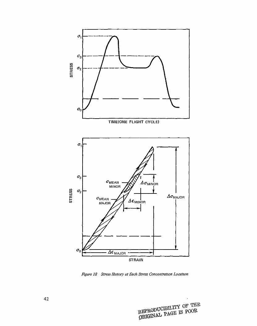
18 Stress History at Each Stress Concentration Location 42
19 P&WA Engine Low Cycle Fatigue - Experience vs. Prediction 43
20 LCF Crack Initiation Life Summary of the Standard, Advanced Standard and Design Disks 44
PAGE NO IV
LIST OF ILLUSTRATIONS (Cont'd)
Figure Caption Page
21 Critical Flaw-Sites for the Standard, Advanced Standard and Improved Design Disks 45
22 LCF Initiated Flaws for the Standard, Advanced Standard and Design Disks 46
23 Schematic of Design Disk Showing TLP®Bond Misalignment 47
24 Crack Profiles for Standard and Advanced Standard Disk Cooling-Air Channel Exit Cracks 48
25 Crack Profiles for Design Disk Cooling-Air Channel Entrance Crack 49
26 Stress Intensity (A K) Values for Bond Misalignment in Web of Design Disk 50
27 JTSD-17 First-Stage High Pressure Turbine Bore-Entry-Cooled Improved Design Disk 51
28 LCF Crack Initiation Life Summary of the Standard, Advanced Standard and Improved Design Disks 52
29 Crack Profiles for the Improved Design Disk Coohng-Air Channel Entrance Crack 53
30 Crack Propagation Life Summary of the Standard, Advanced Standard and Improved Design Disks 54
31 Assumed Fragment Patterns for the Standard and Advanced Standard Disks 56
32 Advanced Fragment Patterns for the Improved Design Disk 58
PAGE NO V

LIST OF TABLES
Table Title Page
I Limiting Concentrated Stress and Limiting Flight Cycle Time Point Summary of Standard, Advanced Standard & Design Disks 9
I Critical Time Points in Flight Cycle 14
III LCF Life Summary of the Standard, Advanced Standard, Design and Improved Design Disks 17
IV Summary of Fracture Mechanics Life Predictions 18
V Crack Propagation Life Improvement of Design Disk 19
VI Total Life Improvement of Design Disk 19
VII Fragment Energy Comparison of Standard, Advanced Standard and Improved Design Disks 22
PAGE NO Vi

SUMMARY
Pratt & Whitney Aircraft conducted a nine month program, under NASA contract NAS3
18558, to study an advanced turbine disk design concept. The objectives of the "Improved
Turbine Disk Design to Increase Reliability of Aircraft Jet Engines" program were to design
a new turbine disk (referred to as the design disk) which could be a potential replacement for
the existing first-stage turbine disk in the JTSD-17 commercial turbofan aircraft engine,
and conduct the analysis necessary to calculate the improvement in disk life and overspeed
capability resulting from the new design.
The design disk studied under this program was a bore-entry-cooled bonded disk In the bore-entry-cooled concept, turbine b.ade cooling air is introduced at the disk bore, pumped radially through internal channels in the disk (one for each turbine blade) and exits to supply the blades at the blade attachment slot at the disk rim. The disk is fabricated in halves in which the cooling air channels are machined. The two disk halves are bonded together at the radial vanes between the cooling channels and at the disk rim using a transient liquid phase (TLP ) bond
A simplified JT8D-1 7 engine flight cycle was used in the disk analysis which included consideration of transient and steady-state temperature, blade loading, creep, low cycle fatigue, fracture mechanics, and manufacturing flaws The design conditions and criteria that went into the design of the existing first-stage high pressure turbine disk for the JT8D-17 turbofan engine were used in the study of the design disk. The same analytical methods were used where applicable m the calculation of temperatures, stresses, and lives for the standard (Bill of Material), advanced standard (Bill of Material disk geometry with material changed from Waspaloy®to an advanced material, Astroloy)-and design disks. The design disk has no deleterious effect on the engine performance as compared to performance obtained with the existing turbine disk. The turbine blade airfoil, and the amount and temperature of the blade coolant were the same as used in the present JTSD-t7 eiigine The diametral growth due to creep of the design disk prior to failure does not exceed that of the standard disk, since the disks are not creep limited The limiting low cycle fatigue (LCF) crack initiation lives of the standard, advanced standard and design disks are 16,000, 18,000 and 30,000 cycles, respectively, and the crack propagation lives are 2900, 1150 and 6500 cycles, respectively. The improvement in life of the initially unflawed design disk over the initially unflawed standard and advanced standard disks is 93% and 90%, respectively, obtained by comparing the total of the number of cycles to crack initiation and the number of cycles during the crack propagation period. The limiting life location in all three disks is at the LCF crack initiation site of the disk. The increase in the crack propagation life for the LCF crack initiated flawed design disk is 465% over the advanced standard disk and 124% over the standard disk. The weight of the Astroloy design disk is the same as that of the existing Waspaloy ® standard disk. The overspeed capability, or burst margin, established by comparing disk burst speed to the maximum speed of the engine for the standard, advanced standard and design disks are 35.6%, 35.9% and 33%, respectively; and they are all above the design minimum of 22%.
Based on disk fracture experience, available kinetic energies of assumed disk fragments were calculated for the three disks. The results indicated smaller fragments and hence lower fragment energies for the design disk as compared to the standard and advanced standard disks.

1.0 INTRODUCTION
1.1 BACKGROUND
A disk burst is potentially the most catastrophic failure possible m an engine and thus disks are designed with overspeed capability and low cycle fatigue life as primary objectives The requirement for higher turbine stage work without additional stages has resulted in increased turbine blade tip speeds and higher turbine inlet temperatures in advanced commercial engines. This trend has resulted in significant increases in turbine stage disk rim loading and a more severe thermal environment, thereby making it more difficult to design turbine disks for specified life requirements meeting current weight goals Indications are that both turbine blade tip speeds and turbine inlet temperatures will continue to increase in advanced commercial engines as higher turbine work levels are achieved. Advanced turbine disk concepts are required to insure long life disks in commercial engines considering both crack initiation and propagation, without resulting in severe weight, performance, or cost penalties.
1.2 PROGRAM
The goal of the "Improved Turbine Disk Design to Increase Reliability of Aircraft Jet Engines" program was to design an advanced concept turbine disk which could be a rotential replacement for a Bill-of-Material first-stage turbine disk in an existing commercial engine and which would have improved reliability with respect to the Bill-of-Material disk. P&WA's approach to achieve the program goal was to increase the cycle life of the turbine disk without increasing the disk weight, while maintaining engine performance.
The Pratt & Whitney Aircraft JTSD-17 turbofan engine was selected as the study vehicle for the improved turbine disk life program. The -17 model is the latest and most advanced version of the JT8D engine which is the most widely used commercial jet engine, supplying power to 45 percent of the world's commercial fleet. The JT8D has been in commercial service for 10 years and over 71,000,000 total engine hours have been accumulated on over 6,600 delivered engines. The current rate of use is approximately 1,000,000 hours and 1,000,000 cycles per month.
Over the years, engine model changes have been incorporated to increase thrust from the original 62,300 newtons (14,000 pounds) for the JT8D-1 to 71,200 newtons (16,000 pounds) for the JTSD-17. Turbine inlet temperatures have increased 1400 K (260°F). The use of air-cooled first-stage turbine blades was initiated with the JTSD-1 1model, and approximately 1300 engines with air-cooled turbine blades have been delivered, of which 235 are the JT8D-17 model. Engineering development to further improve the JT8D will continue for the remainder of this decade. The disk concept studied in this program is applicable to this type of engine in service today and advanced commercial engines.
Pratt & Whitney Aircraft conducted a 9 month analytical study of three first-stage turbine disks for the JT8D-17 engine. The first disk, called the "standard" disk, is the Bill-of-Material (B/M) Waspaloy@ JT8D-17 first-stage high pressure turbine disk. The second disk, called the "advanced standard" disk, is a disk with a geometry identical to that of the B/M disk, but made of an advanced material, Astroloy The third disk is the "design" disk which
2

is a bore-entry-cooled, transient liquid phase (ref. 1) bonded disk, made of Astroloy. The reason for the three disks was to separate the life improvement in the design disk due to the advanced structural concept from the life improvement obtained through the use of an advanced disk material. In the study, the same design conditions, criteria, and engine flight cycle were used for the three disks, and the same analytical methods were used where applicable The disk analysis included considerations of transient and steady-state temperature, blade loading, creep, low cycle fatigue, fracture mechanics, and manufactunng flaws
The improvement m life of the design disk was compared to that of the standard and advanced standard disks. Comparisons were made on the basis of cycles to crack initiation and over-speed capability for initially unflawed disks and on the basis of failure for initially flawed disks. Available kinetic energies of disk fragments for the three disks were also calculated and compared.
Ref. I Duvall, D S,Owczarski, W. A, and Paulonis, D r, "TLP® Bonding A New Method for Joining Heat Resistant Alloys," Welding Journal, April 1974, p. 203-214.
3

2.0 DISK DESIGN
The existing first-stage turbine disk, or standard disk, for the JT8D-17 turbofan engine is shown in Figure 1. Cooling of the high pressure turbine blades is accomplished using compressor discharge air delivered by a conventional tangential on-board injection (TOBI) system. The TOBI turbine rotor cooling air delivery system bleeds high compressor discharge air from the combustion chamber liner and projects this air onto the turbine disk. Work is extracted from the bleed air by trading the higher than required compressor discharge pressure for tangential velocity produced in the TOBI nozzles. That is, the igh tangential momentum produced by TOBI nozzles does work on the conventional turbine disk in the same manner as an impulse turbine. The work accomplished on the disk reduces both the temperature and pressure of the turbine rotor cooling air as it flows to the turbine airfoils. It is important to note that with the TOBI delivery the cooling air is raised to a lugher pressure (i e., more compressor work) than required for turbine airfoil cooling and then pressure is lowered to the airfoil requirement by the removal of work (i e, TOBI work). Each of the 80 turbine blades is then fed air through a drilled hole which delivers air from the point of on-board injection, through the disk rim to the bottom of the blade attachment slot below the blade. The opening of the angled cooling air hole in the disk rim broach results in an elliptical exit opening with high stress concentration and is the limiting low cycle fatigue life location in the standard disk. The advanced standard disk is identical to the standard disk except for a disk material change from Waspaloy @ to an advanced material, Astroloy. The design disk, which has the potential to replace the existing first-stage turbine disk in the JT8D-17 engine, is a bore-entry-cooled, bonded disk
The bore-entry cooled disk concept entails bleeding the turbine cooling air inboard at the mid-compressor and transferring the air axially between the high and low turbine shafts to the bonded disk bore where it is pumped up through the disk in carefully designed internal channels, one for each turbine blade, and exits to supply the blade attachment slot at the disk rim as shown in Figure 2.
Cooling air arriving at the airfoils in tis manner has not been pumped to higher pressures than required for turbine airfoil requirements. That is , compressor work above that required to
reach turbine airfoil pressure has not been added to and removed from the cooling air Thus, cooling air arriving at the turbine airfoils in this manner requires less compressor work than
conventional TOBI systems. The amount of heat picked up by the cooling air as it passes
through the radial air channels in the design disk is small and thus no additional coolant is
needed to cool the turbine blades at the disk rim.
Tailoring the design of the blade cooling air radial pumping passages yields control of the disk radial thermal gradient even during engine transients. The disk is fabricated in halves in which the cooling air channels are machined The two disk halves are bonded together at the radial vanes between the cooling channels and at the disk rim using transient liquid phase (TLP®) bonding
4

2.1 DESIGN CONSIDERATIONS/CONDITIONS/CRITERIA
The design conditions and criteria used in the design of the existing first-stage high pressure turbine disk for the JT8D-1 7 turbofan engine were also used for the design disk. The simplified JT8D-17 engine flight cycle used for the analysis of the standard, advanced standard, and design disks is shown in Figure 3 in terms of altitude, inlet Mach number, turbine inlet temperature, and engine speed versus flight time.
The design disk has no deleterious effect on the engine performance as compared to performance obtained with the existing Bill-of-Material standard disk Neither the turbine blade airfoil nor the amount or temperature of the blade coolant in the present'engine was changed. Provision was made in the disk design for channeling coolant to the blades The dliametral growth due to creep of the design disk prior to failure does not exceed that of the standard disk, since the disks are not creep limited The design properties of Astroloy, the advanced disk material used in the analysis of the advanced standard and design disks, are shown in Figure 4. The design properties of Waspaloy used in the analysis of the standard disk are shown in Figure 5
The configuration of the design disk, in regard to provisions for supplying cooling air to the blades, which was required for the calculation of transient and steady-state radial and axial temperatures was accomplished by introducing turbine blade cooling air into the disk bore/ shaft annulus. Radial air passage channels in the design disk then pump the turbine cooling air from the disk bore to the blade supplying the required pressure at the disk nm (Figure 2) To minimize the pressure losses associated with entrance, friction and turning experienced by the cooling air in the annular passage between the design disk bore and the engine shaft, the design disk bore radius was moved outward 0 25 cm (0 10 inch) relative to the standard and advanced standard designs. This set the minimum bore diameter of the design disk at 12.0 cm (4.70 inches) versus 11 43 cm (4.50 inches) for the existing JTSD-17-first-stage high pressure turbine disk and the advanced standard disk The rim diameter of the design disk is the same as that in the standard and advanced standard disk since all three disks are designed to use the same turbine blade airfoil, blade attachment, disk broach slot and disk sideplate configuration The radial air passages necessary to achieve the required blade supply pressure at the design disk rim while having no deleterious effect on the engine performance are shown in Figure 6.
2.2 DESIGN ANALYSIS
In the calculation of temperatures, stresses, and lives for the standard, advanced standard, and design disks, the same analytical methods were used where applicable. The geometry of the design disk (Figure 6) was configured using both finite difference and finite element techniques The geometry of the advanced standard disk is identical to that of the standard disk. Figure 7 shows a schematic of the standard and advanced standard disks.
The same thermal analysis was used to calculate transient and steady-state, radial and axial temperature gradients for the standard, advanced standard and design disks. P&WA's thermal analysis of a disk provides a complete and continuous temperature map throughout the entire flight cycle. This is required to determine steady state life limits associated with creep and

burst as well as transient conditions which affect low cycle fatigue limits. Steady state limits are examined at critical flight conditions, i.e., the worst combination, of temperatures and rotor speeds. Transient temperatures are examined continuously over a flight cycle to provide a complete time temperature relationship for the entire disk
The thermal analysis is provided through the use of a three-dimensional transient finite element computer solution encompassing convection, conduction, and radiation. The environmental conditions influencing all external surfaces of the disk are defined as a function of time throughout the flight cycle and the metal temperatures along the disk surfaces and within selected interior nodes are generated by the computer deck. The boundary conditions are defined by correlations based on previous engine and rig experience.
Four major computer programs are used to produce the analysis described above. The following paragraphs describe each of these programs
* The first program is a generalized two-dimensional finite element break-up program which takes disk coordinates as input, and creates a fine mesh nodal break-up for thermal analysis. This deck is completely graphics interactive and makes use of digitizing equipment for generating coordinate input. The mesh fineness is variable throughout the part as accuracy requirements dictate. Disk three-dimensional effects must be input by hand
* The second program calculates all heat transfer coefficients and thermal boundary conditions required for thermal analysis throughout an entire engine flight cycle. Input consists of engine flowpath performance parameters, time response of boundary cooling air temperatures, and numerous types of heat transfer coefficient correlations. These heat transfer coefficient correlations are both analytical and experimental, and have been accumulated through years of research and through matching engine transient thermal data.
* The third program is a three-dimensional computer program which takes as input all information from the first two programs and yields all desired disk transient and steady state temperature profiles. This program calculates all conduction, convection, and radiation heat transfer by an implicit solution technique which incorporates a dynamic time step expander and contractor which assures that the transient time step is small enough to insure accuracy, but as large as possible to conserve computer time.
* The fourth program is a computer deck which reads thermal files created by the temperature calculation program discussed above and arranges the data for input into the stress decks for structural analysis.
6
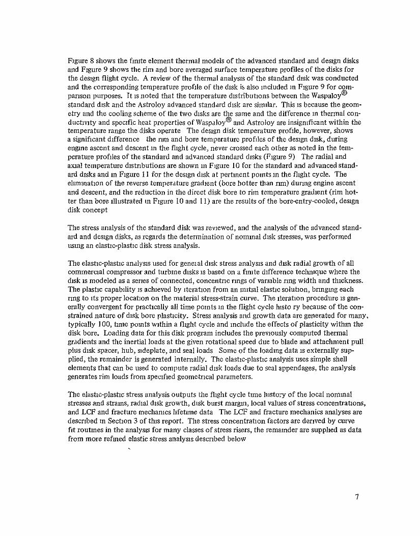
Figure 8 shows the finite element thermal models of the advanced standard and design disks and Figure 9 shows the rim and bore averaged surface temperature profiles of the disks for the design flight cycle. A review of the thermal analysis of the standard disk was conducted and the corresponding temperature profile of the disk is also included in Figure 9 for comparison purposes. It is noted that the temperature distributions between the Waspaloy @
standard disk and the Astroloy advanced standard disk are similar. This is because the geometry and the cooling scheme of the two disks are the same and the difference in thermal conductivity and specific heat properties of Waspaloy @ and Astroloy are insignificant within the temperature range the disks operate The design disk temperature profile, however, shows a significant difference the rim and bore temperature profiles of the design disk, during engine ascent and descent in the flight cycle, never crossed each other as noted in the temperature profiles of the standard and advanced standard disks (Figure 9) The radial and axial temperature distributions are shown in Figure 10 for the standard and advanced standard disks and in Figure 11 for the design disk at pertinent points in the flight cycle. The elimination of the reverse temperature gradient (bore hotter than rm) during engine ascent and descent, and the reduction in the direct disk bore to rim temperature gradient (rim hotter than bore illustrated in Figure 10 and 11) are the results of the bore-entry-cooled, design disk concept
The stress analysis of the standard disk was reviewed, and the analysis of the advanced standard and design disks, as regards the determination of nominal disk stresses, was performed using an elastic-plastic disk stress analysis.
The elastic-plastic analysis used for geneial disk stress analysis and disk radial growth of all commercial compressor and turbine disks is based on a finite difference technique where the disk is modeled as a series of connected, concentric rings of variable ring width and thickness. The plastic capability is achieved by iteration from an initial elastic solution, bringing each rng to its proper location on the material stress-strain curve. The iteration procedure is generally convergent for practically all time points in the flight cycle histo ry because of the constrained nature of disk bore plasticity. Stress analysis and growth data are generated for many, typically 100, time points within a flight cycle and include the effects of plasticity within the disk bore. Loading data for this disk program includes the previously computed thermal gradients and the inertial loads at the given rotational speed due to blade and attachment pull plus disk spacer, hub, sideplate, and seal loads Some of the loading data is externally supplied, the remainder is generated internally. The elastic-plastic analysis uses simple shell elements that can be used to compute radial disk loads due to seal appendages, the analysis generates rim loads from specified geometrical parameters.
The elastic-plastic stress analysis outputs the flight cycle time history of the local nomnmal stresses and strains, radial disk growth, disk burst margin, local values of stress concentrations, and LCF and fracture mechanics lifetime data The LCF and fracture mechanics analyses are described in Section 3 of this report. The stress concentration factors are derived by curve fit routines in the analysis for many classes of stress risers, the remainder are supplied as data from more refined elastic stress analysis described below
.7

In the analysis of the advanced standard and design disks, the elastic-plastic analysis searched the design flight cycle for limiting stress points for the two disks and was consistent with the analysis performed on the standard disk. The stress analysis included effects of blade load, blade-to-disk attachment, thermal stresses, plasticity, acceleration and deceleration transients and other conditions that are considered in current disk design practice. The same analytical techniques were used in the analysis of the three disks where applicable. Figure 12 shows the nominal disk rim and bore stresses of the standard, advanced standard, and design disk. It is noted that the design disk rim has the least extensive stress cycling (stress fluctuation), within one flight cycle, of the three disks.
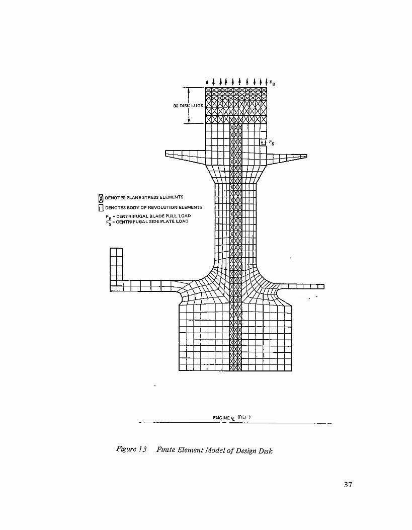
In the design disk, the centrifugal rnm load on the disk is reacted by the bonded bore halves. Since the reactions are not in the same plane as the disk rim load, two couples (moment loads) are introduced in the bonded disk which cause the bore halves to roll toward each other inducing high axal compressive stresses in the disk radial vanes at the ID location. To reduce the local high axial compressive stresses, alternate radial vanes were extended to the disk bore radius as shown in Figure 6. Mixed body of revolution and plane stress finite element techniques were used m the determination of the axial vane stresses. The fimte element analysis utilizes general quadrilateral plate or axisymmetric elements, assembled from constant strain triangles. In the analysis, the design disk structure was modeled using combined plate and axisymmetrical elements, the plate elements were used to model the disk lugs and radial vanes, the axisymmetrical elements were used to model the continuous axisymmetrical hoop material. Figure 13 shows a schematic of the finite element model of the design disk. The resulting axial stress distribution at the bond surface of the design disk is shown in Figure 14. The maximum bond tensile stress is 1.52 x 10⁸ N/cm 2 (22 ksi) and the maximum bond compressive stress is -7.25 x 10' N/m2 (-105.2 ksi) which is below the 0 2% yield strength of the materal. Both of these stresses occur at 56 seconds into theflight cycle.
The same finite element analysis was used in the determination of stress concentration factors (SCF) at pertinent locations in the design disk, such as at the radial cooling air channel entrance and exit locations. Figures 15 and 16 show the finite element models of the design disk broach slot and cooling air channel cross-section, respectively, at the disk rim The finite element model of the cooling air channel cross-section (Figure 16) is typical of analytical models of the channel cross-section at the various disk radial locations such as at the disk web and bore. The pertinent SCF's, the limiting concentrated stresses and their corresponding locations in the standard, advanced standard and design disks are summarized in Table I. The limiting flight cycle time points associated with these stress occurrences are also included m the same table. These time points were the limiting flight cycle time points used in the crack initiation analysis.
Based on the thermal and stress analysis that had been conductdd on the standard disk, creep was found not to be a limiting design consideration and this was also true for the advanced standard and design disks The advanced standard and design disks use the same blades and blade-to-disk attachments as in the existing standard disk. The disk attachments are subjected to the same centrifugal loads and, hence, the same attachment stresses are expected m all three disks. Figure 17 shows the attachment stresses for the three disks at the maxinum engine take-off speed (11870 rpm)
8

TABLE I
LIMITING CONCENTRATED STRESS & FLIGHT CYCLE TIME POINT SUMMARY OF STANDARD, ADVANCED STANDARD & DESIGN DISKS
Disk cm
Location Radius
Inches Remarks
StressConcen-tration Factor
Limiting Stress
108 N/m 2 ksi Stress Type
LimitingFlight Cycle Time Point, Seconds
Standard Disk
21.6 8 51 Rim Cooling Air Exit Hole
345 10.4 151.9 Hoop 874.0
Advanced Standard Disk
21.6 8 51 Rim Cooling Air Exit Hole
3.45 10.3 149 8 Hoop 883.0
Design Disk
21 6 8.51 Rim Cooling Air Channel Exit
3.13 9.8 142.0 Hoop 7.5
Design Disk
17.8 7 0 Web Maximum Radial Stress Location
2 24 9.46 137 6 Hoop 300.25
Design Disk
9.2 3.60 Short Vane 1.D
1.72 9 85 143.2 Hoop 56.0
Design Disk
6 0 2.35 Bore Cooling Air Channel Entrance
1.52
1.2
10.2
-8.75
1480
-127.6
Hoop
Axial
225.25
560
3.0 DISK FAILURE ANALYSIS
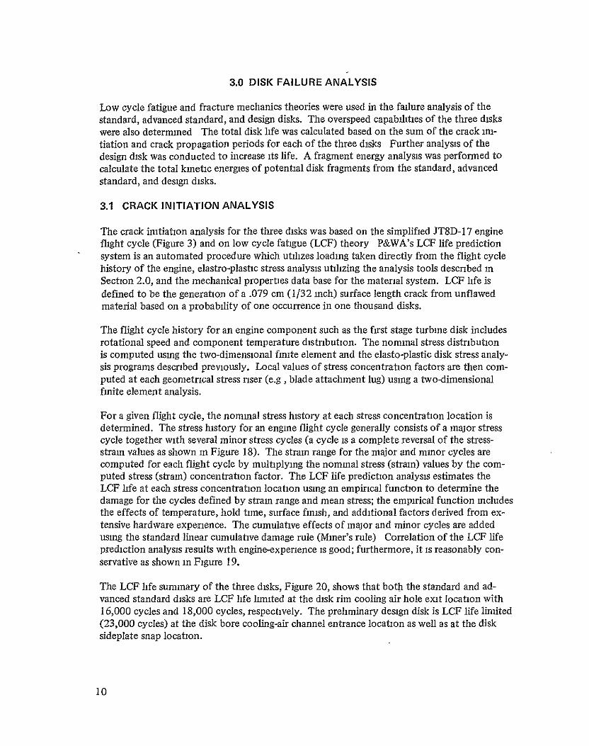
Low cycle fatigue and fracture mechanics theories were used in the failure analysis of the standard, advanced standard, and design disks. The overspeed capabilities of the three disks were also determined The total disk life was calculated based on the sum of the crack initiation and crack propagation periods for each of the three disks Further analysis of the design disk was conducted to increase its life. A fragment energy analysis was performed to calculate the total kinetic energies of potential disk fragments from the standard, advanced standard, and design disks.
3.1 CRACK INITIATION ANALYSIS
The crack initiation analysis for the three disks was based on the simplified JT8D- 17 engine flight cycle (Figure 3) and on low cycle fatigue (LCF) theory P&WA's LCF life prediction system is an automated procedure which utilizes loading taken directly from the flight cycle history of the engine, elastro-plastic stress analysis utilizing the analysis tools described in Section 2.0, and the mechanical properties data base for the material system. LCF life is defined to be the generation of a .079 cm (1/32 inch) surface length crack from unflawed material based on a probability of one occurrence in one thousand disks.
The flight cycle history for an engine component such as the first stage turbine disk includes rotational speed and component temperature distribution. The nominal stress distribution is computed using the two-dimensional finite element and the elasto-plastic disk stress analysis programs described previously. Local values of stress concentration factors are then computed at each geometrical stress riser (e.g , blade attachment lug) using a two-dimensional finite element analysis.
For a given flight cycle, the nominal stress history at each stress concentration location is determined. The stress history for an engine flight cycle generally consists of a major stress cycle together with several minor stress cycles (a cycle is a complete reversal of the stressstrain values as shown in Figure 18). The strain range for the major and minor cycles are computed for each flight cycle by multiplying the nominal stress (strain) values by the computed stress (strain) concentration factor. The LCF life prediction analysis estimates the LCF life at each stress concentration location using an empirical function to determine the damage for the cycles defined by strain range and mean stress; the empirical function includes the effects of temperature, hold time, surface finish, and additional factors derived from extensive hardware experience. The cumulative effects of major and minor cycles are added using the standard linear cumulative damage rule (Miner's rule) Correlation of the LCF life prediction analysis results with engine-experience is good; furthermore, it is reasonably conservative as shown in Figure 19.
The LCF life summary of the three disks, Figure 20, shows that both the standard and advanced standard disks are LCF life limited at the disk rim cooling air hole exit location with 16,000 cycles and 18,000 cycles, respectively. The preliminary design disk is LCF life limited (23,000 cycles) at the disk bore cooling-air channel entrance location as well as at the disk sideplate snap location.
10

The overspeed capability, or burst margin, of the advanced standard and design disks was calculated using the same analytical procedure employed in the standard JT8D-17 first-stage Igh pressure turbine disk design Accurate means of predicting the burst speed of com
pressor and turbine disks have been developed through an extensive program which included the evaluation of the basic tensile properties (yield and ultimate strengths) of disk materials, the calculation of disk stresses, and the correlation of these stresses to the strength of the material through actual burst tests. It has been possible through actual whirl pit tests of approximately 300 disks to determine a correlation between the calculated average circumferential stress at burst and the ultimate strength of the material. Such a correlation has provided a consistent ability to predict the minimum burst speed of compressor and turbine disks. The burst strength of the disk has been related to the mminimum ultimate strength of the material at the average disk temperatures. In all cases, minimum disk dimensions and maximum spacer and rim loads have been utilized and no consideration given to whatever restraining effects spacers and hubs-might offer the disk. Burst margins, established by comparing disk burst speeds to the maximum, or redline, speed of the engine for the standard, advanced standard and preliminary design disks are 35.6%, 35.9% and 28.5% respectively, and they are all above the design minimum of 22%.
3.2 CRACK PROPAGATION ANALYSIS
The crack propagation analysis for the standard, advanced standard, and design disks was based on assumed orientation, size, shape, and location of initial flaws for three critical locations, shown in Figure 21, in each of the three disks using fracture mechanics theory.
The fracture mechanics analysis for predicting crack growth under flight cycle loading is broken into two classes of problems; growth of a subsurface crack from an inherent material defect and, continued growth of a surface crack initiated by LCF loading of unflawed material as descnbed in Section 3.1. In both cases of crack growth, the empirical elastic fracture mechanics correlation of the crack growth rate (daldn) and the crack tip stress intensity factor for each stress cycle (AK) is numerically integrated to determine crack size as a function of cycle numbers. Use of the "influence function" method (ref. 2) in the fracture mechanics analysis for evaluating crack tip stress intensity fields fully accounts for local stress variation at the crack due to geometry changes as the crack grows. The analysis assumes the magnitude and distribution of the forces and stresses in the gross structure are not influenced by the crack itself.
The subsurface crack growth analysis is based on the inherent material defect size, the local nominal stress cycle and mean stress level, the local temperature, and the necessary material parameters. These material parameters include the threshold value of stress intensity factor, the fracture toughness, and the empirical values of crack growth rate as a function of temperature and the ratio of maximum to minimum stress for a stress cycle. The subsurface
(2)' Cruse, T. A. and Besuner, P. M., "Residual Life Prediction for Surface Cracksin Complex Structural Details," Journal of Aircraft, Vol 12, No 4, April, 1975, pp. 369-375.
11

crack stress intensity factor is computed using the theoretical results for a buried flaw, circular in shape, and oriented transverse to the maximum normal stress component. The subsurface crack size is given a statistical variation which may be truncated for cracks larger than a specified mmnum inspection level; the material parameters are also fit to statistical functions to account for real material variability. The fracture mechanics life (cycles to grow a crack to the critical crack size for the local stress cycle) is obtained using an analysis which combines the statistics of flaw size, material properties, and the actual load cycle. The resulting life is based on the probability of one failure in ten thousand disks.
The major difference between the subsurface crack and surface crack problems is the need to account for the effects of both crack size and shape together with the stress gradients inherent to notched geometries. Reference 2 describes the techniques used for simulating surface crack growth including these complexities, numerical modeling of surface cracks is accomplished using the boundary-integral equation techmque.
The boundary-integral equation method of stress analysis differs significantly from finite element stress analysis. A set of constraint equations relating boundary tractions to boundary displacements is solved numerically; the technique requires that only the boundary of the geometry be modeled. Thus the numerical problem of modeling the interior, as done by the finite element method, is avoided, resulting in better resolution of high stress/strain gradients; further, problem size and computer run time are significantly reduced relative to comparable finite element results.
The types of flaws considered in this study can be divided into three categories
* Surface flaws located in the LCF initiation sites at the cooling hole exit of the standard and advanced standard disks and at the cooling channel entrance to the design disk (Figure 22)
* Manufacturing flaws buried in the bores of all three disks.
* Manufacturing flaws in the disk webs including buried flaws in the web of the standard and advanced standard disks, and a flaw at the TLP®bond line of the design disk, propagating from a sharp comer created by a misalignment of the two disk halves during fabrication (Figure 23).
The crack growth rates used in the fracture mechanics life prediction analysis of the three disks are based on 700'K (800'F) crack growth data of conventionally forged Waspaloy @
and Astroloy. The 700'K (800'F) crack growth data was used in the analysis because of limited data available for temperatures between room temperature and 700'K (800F) Use of 7000 K (800F) data is conservative since 700°K (800F) crack growth rates tend to be greater than room temperature rates for these materials, and the temperature rises above this level only at time points in the flight cycle having low stress (Table II).
The stresses and temperatures used in the crack propagation analysis of the three disks were obtained from the results of the flight cycle analysis shown in Figures 9 and 12. The critical time points from the flight cycle analysis and the corresponding nominal stresses and temperatures are summarized in Table II. At the time points of maximum stress (the points used
12

in the crack growth analyses), the temperatures are all below 7000 K (800'F), which is the baseline temperature used for the generation of the crack growth rate data Temperatures exceeding 700'K (800F) are seen only m conjunction with stresses considerably less than the maximum stress value. Local stress profiles and stress concentration factors from finite difference and finite element analysis were included in the crack propagation analyses of the LCF-initiated cracks in the three disks.
In the standard and advanced standard disks, a substantial subcycle in the hoop stress occurred at the rim (Figure 12). In the fracture mechanics analysis, this subcycle was treated as being completely equivalent to the major cycle because the value of maximum stress of the minor cycle is within 10% of maximum stress in the major cycle, and the difference m temperature at the two points could not be accounted for analytically since only one temperature, 700'K (800°F), crack growth data was used. Furthermore, testing on nickel materials shows no significant dwell effects at temperatures considered Therefore, the crack propagation lives quoted for the cooling channel exit locations for the standard and advanced standard disks account for two load cycles per flight.
The crack initiation life as calculated by P&WA's LCF life prediction system is defined to be the generation of a 0.079 cm (1/32 inch) surface crack. This surface flaw was assumed to be semi-elliptical in shape and the orientation of the flaw was such that the plane containing the crack front was normal to the local stress field. The growth of this surface flaw in the fracture mechanics analysis was assumed to propagate in an infinite width structure. This assumption is valid for a surface flaw depth less than or equal to three-fourths of the structural finite width, based on P&WA's rn-house experience. The initial ratio of crack depth to crack surface length (a/c) for the 0.079 cm (1/32 inch) surface crack was obtained by analytically "growing" to the 0.079 cm (1/32 inch) size from a 0.01 cm (0.004 inch) semi-circular crack. Local stress profiles determine the aspect ratio. The initial ratio of crack depth to crack surface length (a/c) is 0.48 for the surface flaw at the cooling hole exit location of the standard and advanced standard disks (Figure 22). The crack propagation lives of this flaw in the standard and advanced standard disks are 2900 and 1150 cycles, respectively; and the corresponding critical flaw size for the two disks is shown in Figure 24. The initial crack depth to crack length aspect ratio of the preliminary design disk is 0.44 (Figure 22) and the critical flaw size shown in Figure 25, is limited at 4900 cycles The critical flaw depths for all three disks are within the size limits of the analytical assumptions noted above.
In the manufacturing of the standard, advanced standard, and design disks, the disks undergo a forging process prior to machining. Because of the forging process, intrinsic material flaws in the disk are assumed to become preferentially oriented parallel to the disk forging flow or normal to the sonic inspection direction. Therefore, the assumed subsurface material flaws (Figure 21) of the three disks are based on a sonically detectable, penny-shaped, flat-bottomed buried flaw of 0.119 cm (0.047 inch) diameter. The crack propagation life prediction system then relates the sonic inspection and material data to a corresponding penny-shaped, buried, flat-bottomed hole normal to the maximum stress direction to determine the crack propagation life of the sonically identified 0.119 cm (0.047 inch) diameter flaw.
The buried manufacturing flaws in the bores of the standard, advanced standard, and design disks were analyzed using the maximum hoop stress in the individual disk bore. The calcula
13

TABLE II
CRITICAL TIME POINTS IN FLIGHT CYCLE
Time Temperature Stress Location Sec. 0 K (OF) 108 N/m 2 (ksi) Direction
1. Design Disk
1. Cooling channel a) 30025 661 (730) 6.73 (97.6) Hoop entrance b) 150.25 670 (746) 6.59 (95.6) Hoop
2 TLP®bond a) 5600 666 (740) 1 52 (22.0) Axial b) 150.25 700 (800) <1.52 (<22 0) Axial
3 Bore a) 300 25 661 (730) 6.73 (97.6) Hoop b) 150 25 670 (746) 6 59 (95 6) Hoop
1I. Advanced Standard Disk
1. Cooling channel a) 152800 522 (480) 3.06 (444) Hoop exit b) 75 25 755 (900) 0.38 ( 5.5) Hoop
c) 7.50 461 (370) 282 (409) Hoop
2 Web a) 7000 650 (710) 5.76 (83.6) Radial b) 300 25 716 (830) 461 (66.9) Radial
3 Bore a) 430.00 695 (792) 6 18 (89 7) Hoop
b) 7000 708 (814) 3.77 (54.7) Hoop
III Standard Disk
1 Cooling channel a) 1519.75 528 (490) 3 10 (449) Hoop b) 73 00 755 (900) 0 24 ( 3 5) Hoop c) 750 461 (370) 290 (420) Hoop
2. Web a) 70.00 650 (710) 5 86 (85.0) Radial b) 298.00 716 (830) 471 (68.3) Radial
3. Bore a) 43000 695 (792) 6 21 (90 0) Hoop b) 70.00 710 (818) 3 59 (52.0) Hoop
a) Point of maximum stress b) Point of maximum temperature c) Stress subcycle (Figure 12)
-1!1RODUCIBLITY OF THDI
ORIGINAL PAGE IS POOR
14

ted crack growth lives for the standard, advanced standards, and design disks are 65,000, 39,000, and 26,000 cycles, respectively, and the corresponding critical flaw diameters are 2.46, 2 46, and 2 11 cm (0.97, 0.97, and 0.83 inches), respectively.
The manufacturing flaws in the webs of the standard and advanced standard disks, under maximum radial stress, were calculated to be 97,000 cycles and 59,000 cycles, respectively. The corresponding critical flaw diameter for both disks at this location is 1 80 cm (0.71 inches) before rapid fracture.
Due to manufacturing tolerance buildup in the design disk, there can be a misalignment at the TLP@ bond surface between the cooling channel vanes of the two disk halves creating a sharp comer at the bond line (Figure 23). It was assumed that an initial crack would occur upon the first load cycle because of the high local stress intensity at the sharp corner although the normal tensile stress in the bond is low, 1.52 x 10⁸ N/m 2 (22 ksi). This crack at the TLP® bond line (Figure 23) of the design disk was analyzed as a two-dimensional crack The geometry is such that the problem does not have an exact solution, therefore, a graph of stress intensity factor (AK) vs. crack length was determined, Figure 26 This analysis shows that the value of AK is above the threshold value only for very short crack lengths. For only slightly longer crack lengths, the value of AK drops well below threshold. This-means that the crack cannot grow, since AKTHRESHOLD is defined as that value of AK below which no growth can take place. Therefore, infinite life was found for this location.
3.3 DISK LIFE IMPROVEMENT
Results of the crack initiation analysis on the design disk indicated that the liniting LCF loca-' tions were at the disk bore cooling-air channel entrance and at the disk sideplate snap, and the-life was 23,000 cycles at each location. In order to improve the LCF life of the design disk, design modifications were made and a re-analysis of the disk was performed In the reanalysis, the original design disk temperature distribution was used because the small temperature variation resulting from the design changes would have an insigificant effect on the disk stresses.
To improve the life of the disk bore, both hoop and axial stresses had to be reduced. A reduction in hoop stress was accomplished by increasing the live bore thickness from 6.35 to 7.19 cm (2.5 to 2.83 inches) (13% increase). However, this increase had an adverse effect on the axial stress at the cooling channel vane ID. Under a centrifugal field, the two bore halves have a tendency to roll toward each other because of the induced moment load in the disk caused by the offset between the centrifugal rim load on the disk and reactions of the bore halves. The rolling movement was aggravated by the bore thickness increase and induced a higher axial stress at the vane ID. To relieve the high compressive local stress, the minimum radial vane thickness was increased from 0.178 to 0.203 cm (0.070 to-0.080 inches). This was accomplished by specifying tighter tolerances on the cooling air channel dimensions at the disk bore. The improved disk bore cooling-air channel entrance LCF life is 30,000 cycles.
15
The weight of the original design disk was 1.36 kg (3 lbs.) lighter-than the standard B/M disk. With a 13% increase in bore material, the weight of the improved design disk equals that of the standard BM disk. This design change would not yield significant, if any, life improvement for the standard and the advanced standard disks. A review of the temperature versus flight time profiles of the standard, advanced standard, and design disks at their respective bores and rims, shown in Figure 9, indicated that the rim and bore temperature profiles of the design disk, during engine descent in the flight cycle, never crossed each other as did the temperature profiles of the standard and advanced standard disks. The elimination of the reverse temperature gradient (bore hotter than rim) during flight descent is the reason that in the design disk the addition of bore material to the disk reduces the circumferential bore stresses while not aggravating the nm stresses of the disk. In the standard and advanced standard disks, the addition of bore material increases the disk bore mass which increases the existing reverse temperature gradients in the two disks by further delaying the thermal response of the disk bore with respect to the rim during engine flight descent. This increased reverse temperature gradient causes the hotter bore to induce more strain on the cooler rim resulting in an increased circumferential stress field at the rm where the standard and advanced standard disks were already LCF limited. /
To further improve the LCF life of the design disk sideplate snap, the original sideplate snap was redesigned to allow for a smoother local stress flow and hence reduced stress concentration and improved LCF life. The critical stress in the sideplate snap is 9.20 x 10' N/n 2
(133.3 ksi). The limiting LCF crack initiation life for the redesigned'sideplate snap configuration is 33,000 cycles, a 43% improvement over the original design life. Figure 27 shows a drawing of the improved design disk. A summary of the limiting LCF crack initiation lives of the disk before and after the design change is shown in Table III. The burst margin in the improved design disk is 33%. Figure 28 shows the LCF crack initiation life summary of the standard, advanced standard and improved design disks.
The crack propagation analysis for the improved design disk was done in a manner paralleling that discussed in the previous section for the original design disk. Table IV compares the life predictions obtained for the improved design disk with those previously calculated for the original design disk. At the cooling channel entrance location, the crack propagation life of the improved design disk is 6,500 cycles which is 32% greater than the original design. Both disks show the same crack propagation life (> l05 cycles) at the TLP®bond line. Figure 29 shows the critical crack size of the surface flaw at the cooling channel entrance location of the improved design disk. Figure 30 shows the crack propagation life summary of the standard, advanced standard and improved design disks.
The improvement in life of the initially flawed improved design disk over the initially flawed standard and advanced standard disks is 124% and 465%, respectively, obtained by companing the number of cycles to failure during the crack propagation perod (Table V). The improvement in life of the initially unflawed design disk over the initially unflawed standard and advanced standard disks (93% and 90%, respectively) was obtained by comparing the totals of the number of cycles to crack initiation and the number of cycles during the crack propagation period (Table VI). A normalized weight comparison between the standard, advanced standard, and improved design disk is also included in Table VI.
16

TABLE III
LCF LIFE SUMMARY OF THE STANDARD, ADVANCED STANDARD, DESIGN AND IMPROVED DESIGN DISKS
Disk Identification
Disk Location
LCF Crack Initiation Life Cycles
Original Design Improved
Design
Standard Disk Rim Cooling Air Hole Exit
16,000
Advanced Standard Disk
Rim Cooling Air Hole Exit
18,000
Design-Disk Rim Cooling Air Channel Exit
30,000 35,000
Design Disk Bore CoolingAir Channel Entrance
23,000 30,000
Design Disk Sideplate Snap
23,000 33,000
17

TABLE IV
SUMMARY OF FRACTURE MECHANICS LIFE PREDICTIONS
1) Surface Flaws at LCF Initiation Sites
a) Design disk cooling channel entrance
b) Advanced standard disk cooling channel exit
c) Standard disk cooling channel exit
2) Manufacturing Flaws at Disk Webs
a) Design disk TLP®bond line
b) Advanced standard disk web
c) Standard disk web
3) Manufacturing Flaws at Disk Bores
a) Design disk bore
b) Advanced standard disk bore
c) Standard disk bore
No. of Cycles
Original Design Improved Design
4,900 6,500
1,150
2,900
>105 > 105
59,000
97,000
26,000 37,000
39,000
65,000
18
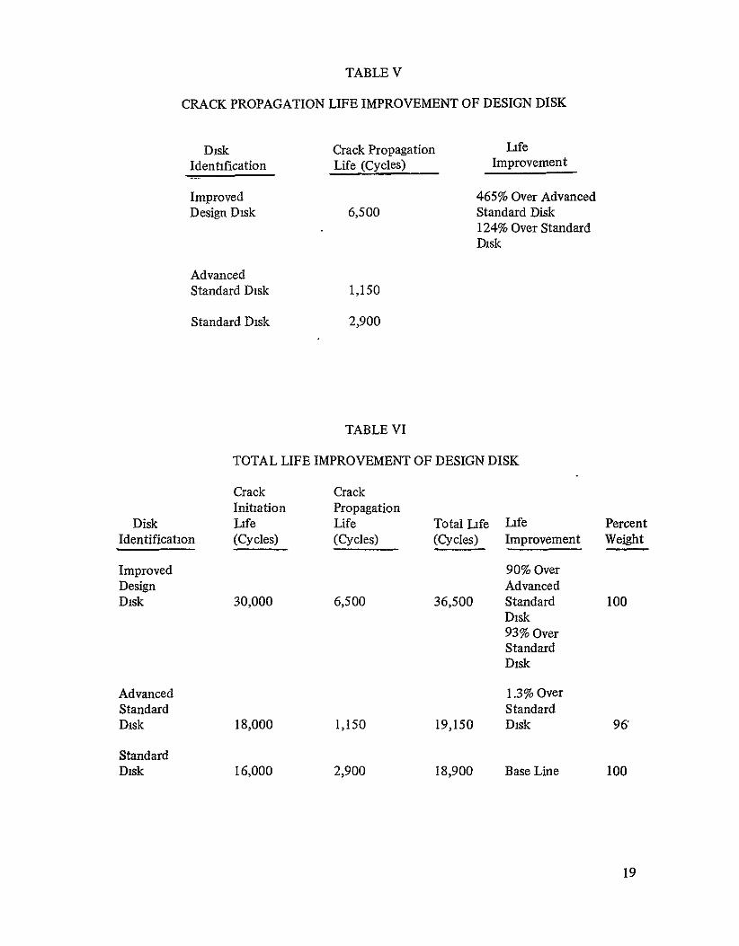
TABLE V
CRACK PROPAGATION LIFE IMPROVEMENT OF DESIGN DISK
Disk Identification
Improved Design Disk
Advanced Standard Disk
Standard Disk
Crack Propagation Life (Cycles)
6,500
1,150
2,900
TABLE VI
Life Improvement
465% Over Advanced Standard Disk 124% Over Standard Disk
TOTAL LIFE IMPROVEMENT OF DESIGN DISK
Crack Crack Initiation Propagation
Disk Life Life Total life Identification (Cycles) (Cycles) (Cycles)
Improved Design Disk 30,000 6,500 36,500
Advanced Standard Disk 18,000 1,150 19,150
Standard Disk 16,000 2,900 18,900
Life Improvement
Percent Weight
90% Over Advanced Standard Disk 93% Over Standard Disk
100
1.3% Over Standard Disk 96'
Base Line 100
19
3.4 FRAGMENT ENERGY ANALYSIS
Based on P&WA's burst experience, the failure patterns shown in Figures 31 and 32 are representative of how the three disks may fail due to crack progression from an LCF initiated flaw or from a buried material flaw. The fragment patterns, used for the fragment energy calculations, include three fragment patterns (size and number of fragments) for each of the three cracks analyzed in the standard, advanced standard, and design disks (a total of 27 fragment patterns).
P&WA's experience would not indicate any significant difference in burst patterns between the standard (Waspaloyf@) and the advanced standard (Astroloy) disks. Also, P&WA's experience would not predict a significantly different fracture pattern for the design disk except that during the actual breakup, the two halves may separate and fracture into two different failure patterns.
The basic fracture mechanism for each of the assumed flaws (Figure 21) in each of the three disks is similar. A crack (or flaw) will progress with the principal stress field (tangential or radial) to a cntical size when the disk will experience rapid fracture. During the course of crack growth, a crack can change direction, branch out into two or more cracks, induce other cracks or progress in one direction until it splits the disk, subject to the load redistribution in the damaged disk As a crack progresses, the centrifugal loads in the disk will cause the fracture surfaces to separate, transferring the load away from the failure origin. The transferring of the load away from the initial crack will cause cracks to form in other high stress locations due to tensile overload Significant progression of two or more of these cracks simultaneously will alter the stress fields in the disk in such a way that the actual failure pattern encompasses two or more fragments Figure 31 shows three possible disk fragment patterns which can result from a surface flaw at an LCF initiation site and the three possible disk fragment patterns which can result from a buried material flaw in the disk web and m the disk bore in the standard and advanced standard disks
The three major locations in the design disk where crack growth and eventual disk fragmentation could occur were also considered. Growth of a radial crack along the bond line due to manufacturing misahgnments may lead to separation of a single vane of the design disk This separation is not critical to engine operation or the engine overspeed burst margin be6ause of the great redundancy of the vane load paths and the fact that the bond surfaces are lowly stressed. Thus, the effect of redistribution and unsymmetry of load due to vane debonding is minimal and was not considered. Standard routine inspection of the disk is expected to locate such vane "debond" cracks. For these reasons, vane "debond" cracking is in a crack tolerant mode and no subsequent disk fragmentation can originate from this mode of cracking. However, these debond cracks can influence the fragment patterns and sizes of an LCF imtiated bore crack or a buried material flaw initiated crack by allowing fractured disk fragments to separate at the bond line. Figure 32 shows the possible fragment patterns which can result from the influence of this manufacturing flaw.
The two other key sites of fatigue crack growth in the design disk are the crack growth in the bore associated with the growth of a buried material flaw and a surface flaw at the coolingair entrance channel. In the presence of the much higher nominal disk hoop stresses of the bore, both modes of disk crack growth will tend to be critical for the load carrying capability of the disk as they will grow transverse to the disk hoop stress and are not likely to stop growmg prior to reaching instability.
20

The design disk concept was assumed to have the capability of restricting these two modes of crack growth to one-half of the design disk. This restriction results from the presence of the radial cooling channels, as crack growth is expected to occur between the channel and the disk free surface. The potential to isolate crack growth to one-half of the design disk differs significantly from standard disk design where crack growth can fail the entire disk load carrying capability by fracture of the disk cross-section. The fragmentation of a portion of a design disk half, however, can effect the integrity of the adjacent disk half by overloading the disk lugs common to both and tearing them off with the fractured disk'fragment. Possible design disk fragment patterns which can result from the LCF initiated bore crack and the buried matenial flaw in the disk bore are also shown-n Figure 32
Fragment energy is defined as the total kinetic energy of a disk fragment (including the attached blades and side plates) upon fragmentation of the disk. The fragment energies of the disk fragments for the standard, the advanced standard, and the improved design disks were computed and are included in Figures 31 and 32. The standard disk made of Waspaloy, and the advanced standard disk, made of Astroloy, have the same disk geometry and disk fragment patterns The small difference m fragment energy between the two disks is due to the difference in densities between the two disk materials. The improved design disk, made of Astroloy, is geometrically different from the standard and advanced standard disks. The improved design disk, characterized by radial bore-to-rim cooling channels machined in two disk halves which are transient liquid phase bonded together, was assumed to result in the confinement of fragmentation to one-half of the disk and thus results in smaller fragments and hence, lower fragment energy as compared to the standard and advanced standard disk fragments, as illustrated in Table VII.
21

TABLE VII
FRAGMENT ENERGY COMPARISON BETWEEN STANDARD, ADVANCED STANDARD AND IMPROVED DESIGN DISKS
Fragment Available Kinetics Energy, Joules (in-lb) @ 11870 rpm Improved
Advanced Design Pattern Type* Standard Disk Standard Disk Disk
27 Blades and Disk Lugs; B 679,000 654,000 Sideplates and 1200 Disk (6,010,000) (5,780,000) Segment
8 Blades and Disk Lugs; E 78,000 75,000 Sideplates and Disk Fragment (690,000) (665,000) Spanning 300 Circumferentially and above 17.8 cm (7.0 in) Radius
27 Blades and Disk Lugs; B 513,000 Sideplates and 1200 Segment (4,540,000) of Rear Disk Half
8 Blades and Disk Lugs; E 72,000 Sideplates and Segment of (633,000) Rear Disk Half Spanning 300 Circumferentially and Avove 17.8 cm (7.0 in) Radius
*Reference Figures 31 and 32
22

CONCLUDING REMARKS
In the design of an increased reliability high pressure turbine disk, P&WA's study emphasized improving reliability by increasing cycle life of the disk without increasing the disk weight and without loss of engine performance. The improved design disk resulting from this study, a bore-entry-cooled bonded disk, could potentially replace the Bill-of-Material first-stage high pressure turbine disk in the JT8D-1 7 engine. This improved design disk has an LCF crack initiation life 87% and 67% greater than the standard and advanced standard disks, respectively Relative to the standard and advanced standard disks, the increase in crack propagation life for the initially flawed improved design disk is 124% and 465%, respectively. The overspeed capability, or burst margin, of the improved design disk is 33%, which is 50% above the design minimum. The unproved design disk made of Astroloy weighs the same as the Waspaloy® standard disk. Based on the assumed disk fragments for the three disks (standard, advanced standard and improved design disks), the improved design disk has the smallest disk fragments and hence the lowest fragment energy. These analytical results indicate that the bore-entry-cooled turbine disk concept has the potential for significant improvements in turbine disk life in advanced engine designs. Therefore, it is recommended that unproved design disks be fabricated and evaluated in fatigue and overspeed tests to verify the analytical results determined in the study
23

ENGINE CENTERLINE
TO REARIN G SUPPORT---
TANGENTIAL ON BOARD-. INJECTION SYSTEM
DRILLED COOLING AIR LIMITING LCF LOCATION SUPPLY HOLE
Figwn eI JT8D-1 7 High Pressure Turbine Disk C oss-Section
A I A T
DISK BORE RADIUS
COOLING AIR
ENGINE (REFERENCE) COOLING AIRPUMPED RADIALLY
FLOW LINESI
UP THE DISK CENTER WITH ONE COOLING
COOLING AIR AIR PASSAGE FOR PUMPED UP EACH TURBINE BLADE
~RADI RADIAL VANES
BOND SURFACE
TAILORED COOLING CHANNEL
FWD DISK HALF FOR OPTIMUM DISK ' THERMAL GRADIENT
I DISK LIVE
TLP BOND RIM RADIUS SURFACE R ON RADIAL VANES
DISK LUG
SECTION A-A
Figure2 Bonded Design Disk Cross-Section
'EPRODUCIBLITY OF THE-
ORIGINAL PAGE IS POOR
24

0.8 TAKEOFF' 1 1 CRIS DESCENT
0
I
02
o ! I I I.
E 8
<" -"
WoLI
-
1600
-1400
< 201 -1
I
600
10
o '.M -
i-n
1 I
I
I
I1 I I I
0510 is 20
FLIGHT TIME -MIN
25 30 35
Figure3 JTSD-1 7 Simplified Engine Flight Cycle
25

84
MEAN COEFFICIENT OF LINEAR EXPANSION
14 - N -
TENSILE PROPERTIES
2 X 12 170
T ENSILE STRENGTH
300 E~~1
40 0 ON N0120 6 5
T3.72
X20
32
30 c
X28
TEMPERATURE OK10
ELASTIC MODULUS
~300
8L ,J
0
I I
2o
I I
NO6ON OF
60090
TEMPERATURE OK
.
9o.o
2 0 41 01 1200THERMAL0 2M0 4W 600 SOO IO 1200
Op
I I I 300 600
TEMPERATURE - OK SOON
140
In120
CONDUCTIVITY
TOO SPECIFIC HEAT
9-
50
06000 140
IM
-
4000 60 6600 CEO
2 1000
2
40000I
______6t___
I0 0 20000
o 6 0
02O2
I 300
I 600
TEMPERATURE- 0K
900
I IC0OO
TEMPERATURE - OK
I900
in6,
CRACK GROWTH RATE VS STRESS INTENSITY FACTOR FOR ASTROLOY
lj-4 -LOW 894K 11
F 11
10-
CYCLE FATIGUE 1
TEMPERATURE CORRECTION
9MFACTOR - KON 4 K 098
0C,09 098
0 400
O ON800 1000 200
2 0 TEMPERATURE OK
5x I×,6 <
< 6XV 0 E
046 INN
CYLE
-0 N02 50 I -"
Fgure 4 Design Properties for Atroloy
26 2- RODUCiBiLiTy Op
LOWGINAL PAGE IS Poop,

TENSILE PROPERTIES
MEAN COEFFICIENT OF LINEAR EXPANSION
14 - 200
Ioo
%< " -Z2 170 TENSILESTRENGTH
g. ISO301~ 60
20 W4 WO0 M 0 IM 0
TEMPERATURE,F
12 00
LZ10
- Y0". IE DMENGTH
66 o wTE TEMPERATURE 0
K
ELASTIC MODULUS
0 130
THEMALCONUCTVIT
P.00200 4 00 00 00 TEMPERATURE,F
10
o il
~ 1404032
24FI0 I 13 SIFICHIA 20 400 600 8) 0 C0 10 2TEMPERATURE. F 60030
TEMPERATUREIS1F04O *KTEMPERATURE mK 8 CSCL FATGU
X 0 g o em 0700 00 12op20
R GRm CRCKGRWH0ATC W HR T SS R SSTRS TEMPERATURE CRRCTOTEMPERATURETEMPERATUREEUFCORCTO
oT
t 0 O LO W CY L F A T IG U EKN .
>"10"4 OP-TEMTPMPATUURE- K
OT
070 5 xS 105 5 0K
" "= 06
I-I 04
10 X 0*0 TEMPERATUR CYCLES$t0000
z5X010--00 -04 -02 0 02=21105
1 50 2000 -3 -2 0 2 3
KSI /N 5MEAN STRESS Xt10 8Nm 2
I I I
STRESS INTENSITY FACTOR (MCK)2NX 10 5Sm Im
FigureS Design Propertiesof Waspaloy@
27

I
749 CM(295 IN)
074 A (029)
BORE
SoR 235) BORE
9 1CM (36 N)
a B
126R 4951
SECTION B B COOLING CHANNEL
SHAPE AT 9 1 CM 1360 IN ) R
" " 0519 CM (020402N
I079
~ 04 FLAT
21 6R (0 985)
38 SECTION A-A Ba51
A
Fgure 6 Schematic of Bonded Diskc With Radial Cooling Air Flow Passages

- ENGINE Q _
BORE 57R
6 3CM (225) (249 IN)
126 R(4.95)
21 6 R C8.5)
LIVE RIM
•"----38 (15)
Figure 7 Schematic of Standardand Advanced StandardDisk
29

U2
z z co
Z3
cc
O
U
REPRODUCEBILITY O
F THE
OR
IGIN
AL
PAG
E IS PO
OR

TAKEOFF-R- i- CLIMB .- CRUISE-..L DESCENT--,,II 750 9 STANDARD DISK TEMPERATURE PROFILES I
00 RM
700I I ILI 600 1BORE
o= 0 oo BORE KS DIAU".I
PEDSTANDARDD,,,,,,,SANT I I '
750AD300 I-1
200
350 I-I900ADVANCED DISKI750 STANDARD
TEMPERATURE PROFILES
700
0 I BORE
wos~ BOR
400
300 I-,
3503U 750 00 BONDED DISK TEMPERATURE PROFILES
700
350 0 2 1111122222333
~600
400
300
350 - 02 4 6 8 10 12 14 16 18 20 22 24 26 28 30 32 34
TIME - MINUTES
Figure9 Disk Rim and Bore Averaged Surface Temperatures vs Flight Time
31

AT 70.0 SECS (END OF TAKE OFF)
AXIAL DISTRIBUTION
RADIALDISTRIBUTION
/
/
-7 00
F R
AXIAL
LENGTH
FO RWAR
H
RE /-AR
'00 FC7 W
00
. , AXIAL
(F) (Rl)4 o /-o IAXIAL
F R LENGTH
- .- - . . . ..- - - - - - -
-- ------ -
50 O
-
0 00010 -
7[
4000 L I 80I
Ix
F
/
1 R
AXIAL
AXIAL LENGTH
E0 6(X) 700 EGG 90 VX-
500 I00 700 8FT AVE TEMPERATURE I- K
00 AXIAL
b. AT 790 SECS (END OF CLIMB)
AXIAL DISTRIBUTION
7O 0
RADIAL DISTRIBUTION
S- F R LENGTH
__ SIX I- AXIAL70
FORWARD REAR HF a
(F) i
AXIAL
LENGTH
-- - - - - - - - - - - AXIAL:[LF A0 LENGTHF0
I I II
SIX MRP7 1I O F R LENGTH OF
50 6(X) 700 MC AVE TEMPERATURE I "
K
Figui e 10 Radial and Axial Temperature Distribution in Standaid and Advanced Standard Disks at Pertinent Points in the Flight Cycle
REPRODUCIBILITY OP TIM ORIGINAL PAGE IS POOR
32

--
C. AT 1390 SECS (END OF CRUISE)
RADIAL DISTRIBUTION
AXIAL DISTRIBUTION
- - - AXIAL F R LNZ
FORWARD REAR -to6 I I AXAL
(F) (RF ... LENGTH
-AaI
. . . . AXIALSOO - - X PO oo0 _______ -
-
------------------------------ ------- LE-------
SOO IAXIALM[I ERF R LENGTHF R
~ ~ o~L IAXIAL 500 M0 70 M0 90 00 P N GT
p I I I 500 00 700 00
TEMPERATURE oK
d. AT 1990 SECS (LANDING)
RADIAL DISTRIBUTION AXIAL DISTRIBUTION
400
350 400I R R
------ I I AXIALIF- -(FR)_ - -- - - - _ _.350 L LENGTH FoW AXIAL
S 400 AXIALFOR ARD RE0AR
10 03(RI 3350 R LENGTH
-- -- - - - - 450[- - - - J 3 40 F R LENGTH
AXIAL
II I I.400
~350[F~-> IAXIAL 100 J.. 5W, 50R LENGTH
OF
AVE TEMPERATURE - OK
Figure10 RadialandAxial TemperatureDistributionin Standardand Advanced Standard Disks atPertinentPointsin the Flight Cycle (Cont)
33

a. AT 70 SECS
(END OF TAKEOFF)
RADIAL DISTRIBUTION AXIAL DISTRIBUTION
9X)AXCIAL.
7MM LENGTH
FORWARD REAR (F) (I)
F R
= ;' 700 800 7W M
F
7OW
SIX 700 M FR
I L oF
500 600 O00 AVG TEMPERATURE OK
b. AT790SECS (END OF CLIMB)
RADIAL DISTRIBUTION AXIAL DISTRIBUTION
-------------------------------- [! 700[
i
AXIAL
LENGTH
P R ..0 70
FORWARD REAR 2 0 0 F R (F) (RI
-JF
650 700 F R
. . . I 550
F FR
11[71)(700 I
064Y7000 F R F FO
I I I 650 600 700
AVE TEMPERATURE - OK
Figure11 RadialandAxial TemperatureDistributionin the Design Disk at PertinentPoints in the Flight Cycle
34

--------------------------
c AT 1390SECS
(END OF CRUISE)
RADIAL DISTRIBUTION AXIAL DISTRIBUTON
750 S00
I jIAXIALI 050[ 7o LENGTH 700F R
\A- Ioo 700i FO)AR REAR z8000
/1 '700 800
700
700 S00
700 600[
0 FF
L. I I 500600700No000
500 600 700 50
AVE TEMPERATURE oK
d. AT 1990 SECS(LANDING)
RADIAL DISTRIBUTION
AXIAL DISTRIBUTION
400 -- 300 AXIAL
N N.--3 200 LENGTHL F
400 450[ o I ,
0 R
FORWARD HEAR <
(F) (R)0
,200 \\ =I I 0
40)
I3I150[ 200 F R
200 34 400 500
OF
'1,0 ,O~O 0
AVE TEMPERATURE -k
Figure 11 Radialand Axial TemperatureDistributionin the Design Disk at PertinentPoints in the Flight Cycle (Cant)
35

TAKE OFF CLIMB I DESCENT
7 cn o STANDARID DISKI
RIM TANGENTIAL 3
4
w 20
'A 1
RIM RADIAL
,a "-ADVANCEDSTANDARD DISK S80 -E
2 0
oDESIGN DI____S__K
N -o ORETANGENTAL - 60 1 RIM TANGENTIAL
Z 4
2 1 RIM RADIAL
o L I01 I I I 20 40 60 80 100 120 140 160 3 7 11 15 19 2 27 31:4
TIME - SECONDS .1 TIME MINUTES
Figure 12 Nominal Disk Rim andBoie Stresses at Various Flight Conditions
fIPODU 1BILTY OF THE 36 W161NAL PAGE IS POOR
80 DISK LUGS
4 41441 4 14IF
uF S
f DENOTES PLANE STRESS ELEMENTS
DENOTES BODY OF REVOLUTION ELEMENTS
FB = CENTRIFUGAL BLADE PULL LOAD
FS = CENTRIFUGAL SIDE PLATE LOAD
ENGINE CL (REF)
Fgure13 FiniteElement Model of Design Disk
37

40
03
00 2
20
0 0 - -
-20
C?
-2 X
-40
-60
I-8
AXIAL STRESS AT 56 SECONDS INTO FLIGHT CYCLE
-100 30 40 50 60 70 80 90 100
I ~INCHES I I
10 15 20 25
RADIUS - CM
Figure14 Design Disk Axial Stress vs Radius Along Bond Surface

VIEW A
4IS ..A L.V V.E
2I ADU
+- RA+A
4 HOOP
einDs rahSo7zue1 mt lmn oelo
3 till POUCBLT O4GIA pAEiP0
3

0r
SECTION A-A
Fgure 16 Finite Element Model of Design Disk Cooling Air Channel

BLADE ROOT CONNECTIONS
TOOTH NO .
TOOTH NO 2
,,TOOTH NO. 4
BROACH SLOTBROACH SLOT
STRESS CALCULATED AT MAXIMUM ENGINE SPEED (11870 RPM)
TOOTH SHEAR TOOTH BEARING
TOOTH OF THE DISK LUG STRESS STRESS STRESS
2 8 2 8 N/m 2
TENSILE STRESS IN NECKS TOOTH BEND
NO 108 N/m 2 KSI 108 N/m KSI 10 N/m KSI 10 KSI
1 201 291 1.84 26.7 1 52 220 433 62.8
2 255 370 157 227 150 21.7 415 602
3 279 404 156 226 150 217 415 602
4 294 42.6 268 389 1 34 194 447 64.8
Fzgu e 17 CentrifugalStresses at the Disk/Blade-Root Connection
O'o
TIME(ONE FLIGHT CYCLE)
U3
47MEAN MINOR
AgMAJORw O'MEAN MINORMAJORCo
aO.AEMAJOR
STRAIN
StressHistory atEach Stress ConcentrationLocation Figure18
pwRD~lC]B~yOF TE 6BIGIAL ISPOOR
42

99.9
990 S
90.0 1
632
PERCENT 500
CRACKED I
0.079 CM 20I
(1/32 IN.) I
50
I I I I 1 11 1
., .5 10 5.0 10.0 50 100
ACTUAL CYCLES TO 0.079 CM (1/32 IN.) CRACK PREDICTED CYCYCLES TO 0.079 CM (1/32 IN.) CRACK
Figure19 P&WA Engine Low Cycle Fatigue- Experience Vs. Prediction
43

STANDARD DISK ADVANCED STANDARD DISK DESIGN DISK
- ENGINE Q - -ENGINEQ - -... ENGINE Q__
>10 5 CYCLES > 10 5 CYCLES >10 5 CYCLES"S23,000 CYCLES
I -
,000 18,000 30,600 23,000
CCL ECYC-LES CYCLES
MARTL WASPALOY ASTROLOY ASTROLOYBURST MARGIN 35.6% 35.9% 28.5% %WEIGHT 100% 96% 96%
*DESIGN MINIMUM 22%
Figure20 LCFCrackInitiationLife Summary of the Standard,Advanced Standardand Design Disks

LIVE-RIMI LIVERI
LIVE-RIMLV
/ 1/01 LIE RIMRELIEBRRM
2
BOREBORE BORE
STANDARD DISK (WASPALOY) ADVANCED STANDARD DISK (ASTROLOY) DESIGN DISK (ASTROLOY)
FLAWFLAWFLAW LOCATION LOCATION LOCATION
CRITICAL LOW CYCLE FATIGUECRITICAL LOW CYCLE FATIGUE CRITICAL LOW CYCLE FATIGUEO INITIATED FLAW SITE AT INITIATED FLAW SITE AT COOL- 'Y INITIATED FLAWSITE AT
COOLING AIR CHANNEL ENTRANCECOOLING AIR HOLE EXIT ING AIR HOLE EXIT
E CRITICAL MANUFACTURINGCRITICAL MANUFACTURING CRITICAL MANUFACTURING FLAW AT DISK BOREFLAW AT DISK BORE0 FLAW AT DISK BORE
CRITIC MANUFACTURING FLAW
FLAW AT DISK WEB MAXIMUM kJ FLAW AT DISK WEB MAXIMUM AT TLP (B) BOND LINE IN RADIAL VANE' RADIAL STRESS LOCATION
Q CRITICAL MANUFACTURING CRITICAL MANUFACTURING
RADIAL STRESS LOCATION
A Figure21 CriticalFlaw-Sitesfor the Standard,Advanced Standardand Improve Design Disks

STANDARDDDISK (WAEPALOYN
ADVANCED STANDARD DISK (ASTROLOY),.-a
a/R' = 40
"THERAT10 OF a/c WAS ANALYTICALLY DETERMINED BASED ON THE LOCAL
STRESS PROFILES
{~( /322IN)
./' = 4
STRODUESSIT PROFILE
BORE
LIV RM AR HANELERANCELCAEON POR ANCED SONA DISK (ASTROLOY) P

A
7 49 12 95
,'74
)
29)
9CMR
(235 IN) BORE
1268 (495)
F .9CM 90 0791NI (NOM)
1278R iS O?
RADIAL VANEBULUNO)(20
S 13 MISALIGNMENT TOLERANCEDUE TO (0 )0 74
POINT OF MAXIMUM"
AXIAL TENSILE STRESS
RADIAL COOLING(TPCL AIR PASSAGE
003 010
21 6 R
(85)
LIVE RIM=
- -SECTION B B
CALCULATED INITIAL CRACK LENGTH AT WHICH THE INFLU-ENCE OF THE SHARP CORNER
BECOMES NEGLIGIBLE
(150) SECTION A-A
Figure23 Schematic of Design Disk Showing TLP®Bond Misalignment

DIAMETER FROM COOLING CHANNEL - CM
10 05 0 I INCHES I
040 035 030 025 020 015 010 005 0
w I I1 0 0 1150
CYCLES FROM 0 079 CM(1/32 INCHI-CRACK (ADVANCED STANDARD DISK)
* 1050 101000
900 005
800
(700 0000
010 S
If /4000 f0
25 600 Z
1700 CYLE RO 001C 35 0
1950 020 05
2250<
CYCLES FROM 0 079 CM 02 (1/32 INCH) CRACK 260002 (STANDARD DISK) 140 I-4 340 -- 0
290 03 z 30
-035
0 -040 10~
CRITICAL CRACK SIZE
488
Figure 24 Crack Profilesfor Standardand Advanced Standard Disk Cooling-Air Channel Exit Cracks
48
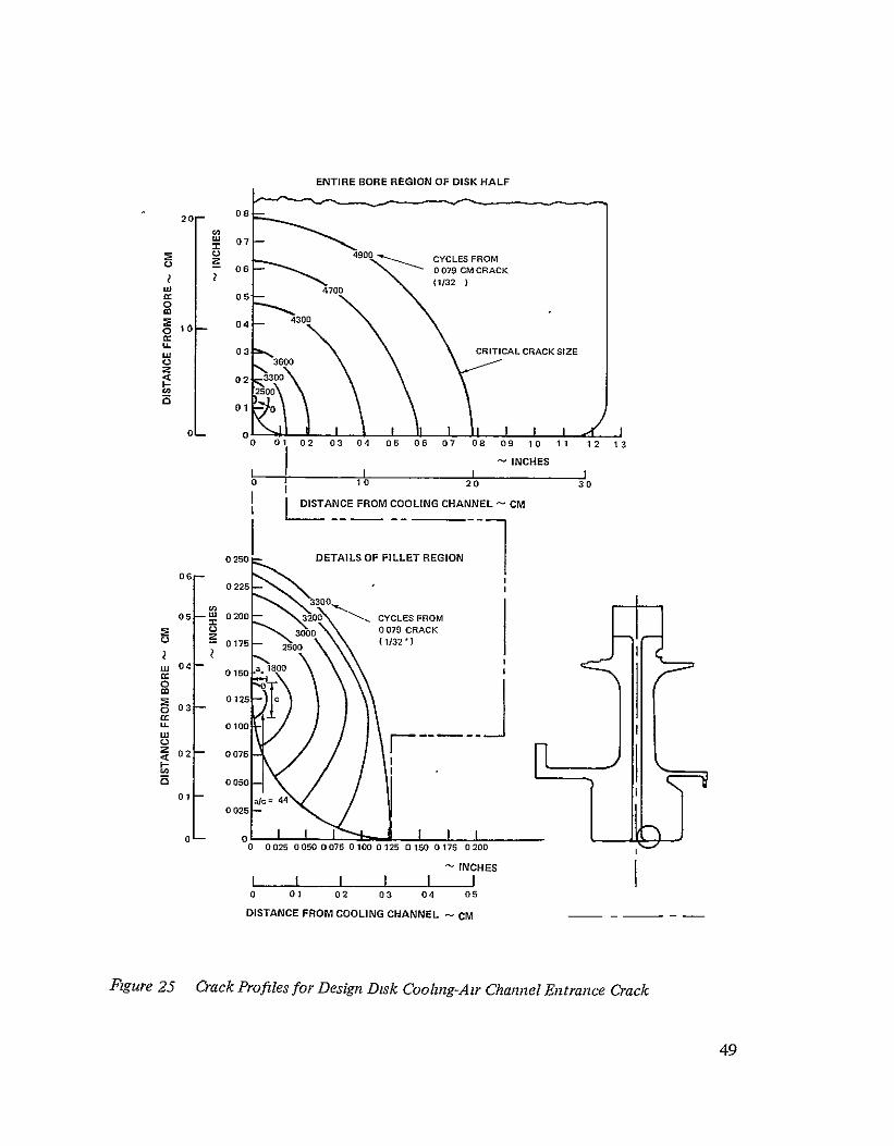
ENTIRE BORE REGION OF DISK HALF
020-
07 204900 CYCLES FROM - 06 0079 CM CRACK
(1132) LU 470005
0
0 04 4300
at 03 CRITICAL CRACK SIZE 3600
02 3300
CO-2500 01
0
0 01 02 03 04 05 06 07 08 09 10 11 12 13
I- INCHES III 0 10 20 30
DISTANCE FROM COOLING CHANNEL - CM
0250 DETAILS OF FILLET REGION
0 225
3300 05 U 0200 3200 CYCLES FROM
00 0079 CRACK
0175 2500 (1/32') 3000
015O
0125 03
Ca'i 0100
0
I )02 0076
o050a
01[ 01 02 alc=44 0025
I0 I 0 0025 0050 0075 0100 0125 0150 0176 0200
INCHES I I I I I I 0 01 02 03 04 05
DISTANCE FROM COOLING CHANNEL CM-
Fgure25 CrackProfilesforDesign Disk Coohng-Air ChannelEntrance Crack
49

10
10
9
AK THRESHOLD
8
7
6
50
0 46CM
I-us (180 IN) T 4 (0 170IN) 074 CM
Nal (0 290 IN)
12 KS I
2
[ 1 I
I I I I 1 0 0002 0004 0006 0008 0010 0012 0014 0016 0018 0020 0022 0024
-a IN
0 1 2 3 4 5 6 CRACK LENGTH -MIA1
Figure 26 Stress Intensity (AJ) Values for Bond Misalignment In Web of Design Disk
so
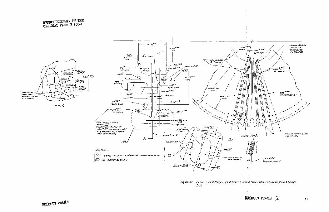
OPXG~bAL PAGE is PO
A
//~
vIOw) CR~
27 TD- 7 F ir,-Stage H gh P~resuseTurbie Bore-Entry-Cooed mp o ed DeignF qxure
Disk

STANDARD DISK
- - ENGINE I_ - -
>105 CYCLES
ADVANCED STANDARD DISK
- - ENGINE
>10' CYCLES
IMPROVED DESIGN DISK
--- E..NGINEI
>10' CYCLES>
30,000 CYCLES
I\
16,000 18,000 35,000 CYCLES CYCLES YCLES CYCLES
MAT'L WASPALOY® ASTROLOY ASTROLOY BURST MARGIN' 250% 359% 33%%WEIGHT 100% 96% I00%
*DESIGN MINIMUM 22%
Fgue28 LCF aeekInittatzn Life Summay of the Standard,Advanced Standardand Improved Desgn Dt
0
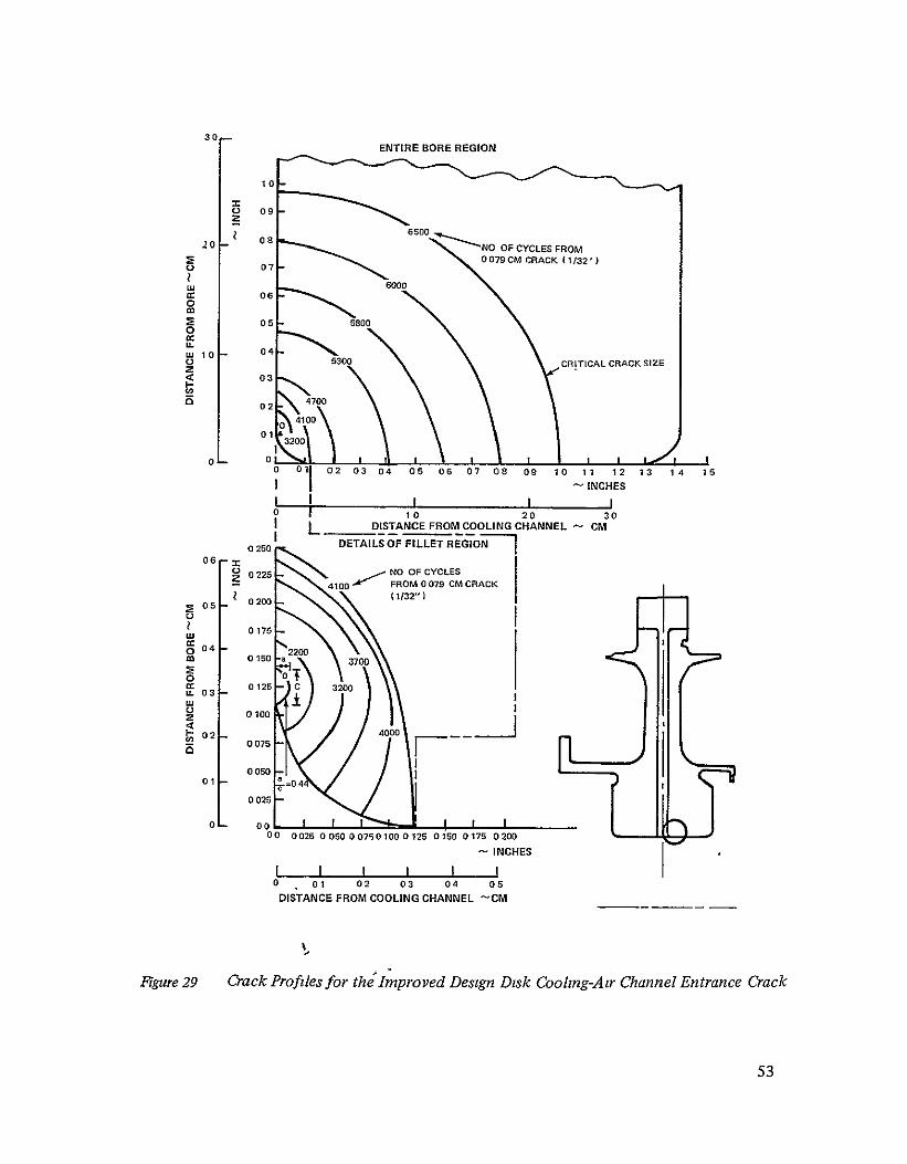
30 ENTIRE BORE REGION
0
20
.20
0
081
0 7 -
6500 Z--N. O CCESFO
CLES F0 7 9 CM CRA CK ( 1132 '1
-RAC
a 00
030
10 04 O
05300
CRITICAL CRACK SIZE
0 01
0f L
02 03 04 05 06 07 08 09 10
I I 0 20
DISTANCE FROM COOLING CHANNEL
11 12
- INCHES
I 30
- CM
13 14 is
06
05
-
0250
0225
0200
-
DETAILS OF FILLET REGIONJ
OOF CYCLES 4100 FROM 0079 CM CRACK
( 1/32"1
w 0175
O 0 0 0150
2200 a 3700
O 03
z 07
0125
0100
C
1CH
3200
70
02 - 400 3
0075 IIN
01-0050
05025
a=0 4
00 0025 0 050 0075 0100 0125 0 160 0 175 0200
-I NCHES
0 01
DISTANCE
02 0a 04
FROM COOLING CHANNEL
05
-CM
Fgure29 CrackProfilesfor thJImproved Design Disk Cooling-Air Channel Entrance Crack
53

STANDARD DISK ADVANCED STANDARD DISK IMPROVED
DESIGN DISK
- -ENGINE q - - ENGINE --- ENENGINE q- -
65,000 37,000
CYCLES 39,000 6,500 CYCLES CYCLES CYCLES
05CYCLESCYCLES>15 CYCLES
I2900 10 CC
MAT'L WASPA LOY ASTROLOY ASTROLOY
BURST MARGIN' 356% 359% 33%
%WEIGHT 100% 96% 100%
*DESIGN MINIMUM 22%
Fsgure 30 Crack PropagationLife Summary of the Standard,Advanced Standardand Improved Design

FRAGMENT PArERNS FROM A FLAW BURIED
FRAGMENT PATTERNS FROM A SURF,ACE RIM FLAW IN THE DISK BORE
LA STANDARD DISK ADVANCED STANDARD DISK STANDARD DISK ADVANCED STANDARD DISK
FRAGMENTI TYPE
A A
2 FRAGMENTS 2FRAGMENT3 FRAGMENTS 3FRAGMEITS
INITIAL FLAW
INITIAL FLAW
B B
1200 12 200 1200AA
+
SNT FRAGMENTS FRAGMENTS
300 300
DD INITNITIA
Ra B 1 B 1200 20 1200 +0200
1200 1200
A * 190C17125) FLAW
1FRAGM ENT 1FRAGM ENT 3FAMNS3RGET
Figure 31 Assumed FragmentPatteinsfor the Standaidand Advanced StandardDisks
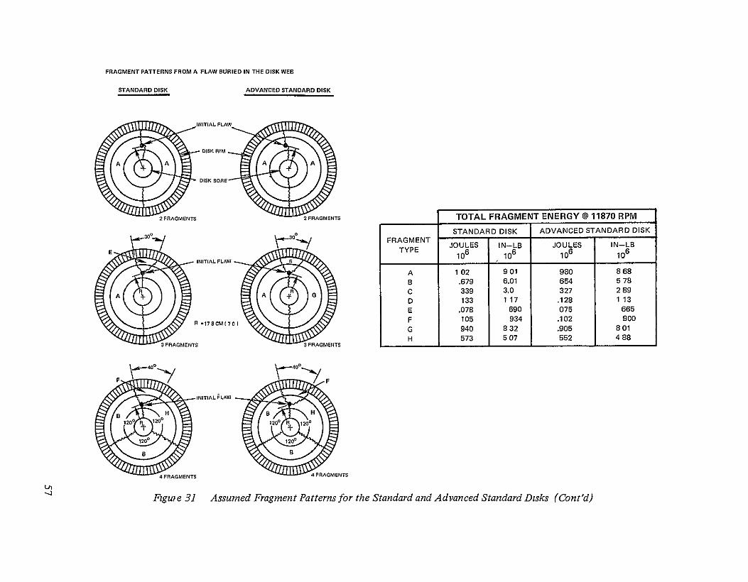
FRAGMENT PATTERNS FROM A FLAW BURIED IN THE DISK WEB
STANDARD DISK ADVANCED STANDARD DISK
INITIAL FLAW
DISK<RIM
(D ~DISKBORE 0
2 FRAGMENTS 2FRAGMENTS TOTAL FRAGMENT ENERGY@ 11870 RPM
STANDARD DISK ADVANCED STANDARD DISK 30 30 FRAGMENT JOULES IN-LB JOULES IN-LB
E TYPE o6 6 06 106 INITIAL FLAW E__________________
A 1 02 901 980 868 B .679 6.01 654 5 78
A A C 339 3.0 327 289 D 133 117 .128 113
E .078 690 075 665
F 105 934 .102 900R *I7SCM(70
G 940 832 .905 801
H 573 507 552 488 3 FRAGMENTS 3 FRAGMENTS
INITIAL FLAW
4 FRAGMENTS
Fguie 31 Assumed FragmentPatternsfor the Standardand Advanced StandardDisks (Cont'd)

FRAGP
LA
FRAGMENT PATTERNSFROMA SURFACEFLAWAT THE COOLING AIR CHANNEL ENTRANCE FRONTHALF
REARHALF
FPPNO
goGMN pATE FRGMEN A URACFA F/P.FRAGMENTPATTERN
FRAGMENT PATTERNS FROM A SUBSURFACEFLAW BURIEDIN THEDISK BOREFRONTHALF REARHALF
3.
iIENT
,F/.FRAGMENTPATTERN
INITIALrLA
EN0INE IREI
E 1NGIN . ' EFI
'GoF 810 2NI
FRAGENT [FLAWAT
INITIAFLAW 0SITE
LCPFINITIATION 60"
g
F 4RGET
2 RABMEO
o o
H0GE SUBSURFACE FLAW
'P reNO
FRAGMENT
S I20COTOENR
I1117A
48013
FRONT18PI TEAR
5 2goo
F/"P
1HALF
3
FIG
I-GR
AL2
FT20021,
Figure32 Assumed FragmentPatternsfor the Improved Design Disk

____________
FRAGMENT PATTERNSFROMTHEIN FLUENCE OFA MANUFACTURING FLAWAT THE BONDLINE
REARHALF *F/M* FRAGMENT PATTERN FRONT HALF
1FRAGMENT
ENGINEC._IREFII R
TOTAL FRAGMENT ENERGY @11870 RPM MANUFACTURING
FLAWAT DESIGN DISK FFFNO2 BONDLINE FRAGMENT
No o JOULES IN-LB TYPE 106 106
C A 385 3A0 454FRONT- t-REAR B .513
HALF A_HALF C 256 2 27 D 171 1 51 E .072 633
F 097 855 G 064 .570 H 441 3.91
LIVE RIM
30~ F/P NO 3
121 816. A 17 8) 70
Figure32 Assumed FragmentPatternsfor the Improved Design Disk (Cont'd)
I

LIST OF SYMBOLS
a/c crack depth to crack length (surface crack)
BIM Bill-of-Material
BTU British Thermal Umts
cm centimeters
OF degrees Fahrenheit
ID inner diameter
in inches
J Joules
OK degrees Kelvin
Kg kilograms
ksi 1000 pounds per square inch
LCF low cycle fatigue
m meters
mm mllimeters
N Newtons
psi pounds per square inch
RPM revolutions per minute
SCF stress concentration factor
TLP® Transient Liquid Phase bonding process
AK stress intensity factor
e strain
60

DISTRIBUTION LIST
Commanding Officer U. S. Army Air Mobility and Dev. Lab. Fort Eustis, VA 23604 Attn Leroy Burrows
Commanding Officer Ballistic Research Laboratories (USA-ARDC) Aberdeen Proving Ground, MD 21005 Attn AMXRD-BAM
N. J. Huffington, Jr 1 J Santiago 1
Commanding Officer U S. Army Materials and Mechamcs Research Center Watertown, MA 02172 Attn AMXMR-ED
J Adachi 1 J. I Bluhim 1 T Tsui 1
U. S. Army Dept. of Armed Force Development The Pentagon RM. 3D463 Washington, DC 20301 Attn: Lt. Col. George Ivey I
Naval Air Propulsion Test Center Propulsion Technology and Project Engrg. Dept. Trenton, NJ 08628 Attn C. J. Mangano 1
Commanding Officer Naval Aviation Safety Center Norfolk, VA 23511 1
Director, Naval Research Lab. Washington, DC 20390 Attn Library, Code 2029 (ONRL)
Office of Naval Research Washington, DC 20360 Attn N. Basdekas I
Office of Navy Research U. S. Navy Branch Office, London P.O Box39 FPO, NY 09510 2
Air Force Flight Dynamics Laboratory Wright-Patterson AFB, Oluo 45433 Attn F J. Janik, Jr., FDTR 1
R. M. Bader, FDTR
AF Office of Scientific Research. Aeromechanics and Energetics Div. Arlington, VA 22209 1
AF Systems Command Structures Division Design Criteria Branch, Code FDTE Wright-Patterson Air Force Base Ohio 45433 1
National Aeronautics & Space Admin Lewis Research Center 21000 Brookpark Rd Cleveland, OH 44135 Attn- Albert Kaufman, M.S 77-2 5
John H. Weeks, M S 5-3 1 Warner L Stewart, M S. 3-5 1 Solomon Weiss, M. S 6-2 5 Richard H. Kemp, M S. 49-1 1 Marvin H T-hrschberg, M. S 49-1 1 Reginald Pagmton, M S 500-206 1 Norman T. Musial, M. S 500-113 1 Library, M. S. 60-3 2 Report Control Office, M S. 3-19 1 Technology Utilization Office,
M. S. 3-19 1
National Aeronautics & Space Admnn. Washington, DC 20546 Attn. John H. Enders, Code ROO 1
George W. Cherry, Code RD-P 1 Nelson F. Rekos, Code RLC I Kenneth E Hode, Code RO I
NASA Scientific & Technical Information Facility P 0. Box 8757 Balt./Wash International Airport MD 21240 Attn: Accessioning Dept. 40
61
DISTRIBUTION LIST (Cont'd)
Civil Aviation Authority Aeronautical Research Associates of Princeton Airworthiness Division 50 Washington Rd. Brabazon House Princeton, NJ Red Hill, Surrey Attn I. C Houbolt England Attn L R Wilson 1 AiResearch Manufacturing Co of Arizona
G. L. Gunstone 1 Division ofGarrett Corporation 402 South 36th Street
Ministry of Transport Phoenix, AZ 85034 Canadian Air Transportation Admin. Attn E. L. Wheeler No. 3 Temporary Building Technical Library Wellington St. Ottawa, Ontario AVCO Space Systems Division Canada Lowell Industrial Park Attn D. R. Hemming Lowd, MA 01851
Director, Planning & Research, Air 1 Attn Charles Steward
Federal Aviation Administration Batelle Memorial Institute 800 Independence Ave, S W. Columbus Lab. Washington, DC 20591 505 King Ave Attn Robert Auburn, Code- AFS-140 1 Columbus, OH 43201
Elmer Briggs, Code. AFS-140 I Attn. S Goddard A K Forney, Code AFS-141 1
The Boeing Co Federal Aviation Admm. Chief Engineer - Turbine Engineering & Manufactunng Branch Seattle, WA 98124 N. Y. International Airport Attn H Cruver Jamaica, L I., NY 11430 Attn: Lewis C Smith, Jr. 1 The Boeing Co.
Richard Grassler, Code AFS-302 1 ASG Impact Mechamcs Labs. William McAdoo, Code. ARD-500 1 Seattle,WA 98124 Edward B Shilke, Code. AFS-320 1 Attn. J Lundeberg
Federal Aviation Administration The Boeing Co. Flight Standards Division SST Branch 2300 East Devon Ave. Seattle, WA 98124 Des Plaines, IL 60018 Attr. Robert Stoddard Attn Lou Smith, Code: AGL-214 1
The Boeing Co. Federal Aviation Administration Commercial Airplane Group 12 New England Executive Rd Seattle, WA 98124 Burhngton, MA 01803 Attn. Jack N. Funk Attn Robert Berman, Code ANE-214 1 Richard B Clarke, MS 78-81
Technical Library National Transportation Safety Board 800 Independence Ave., S W. Continental Aviation & Engineering Corp Washington, DC 20591 Advanced Design and Materials Technology Attn: Douglas Dreifus, Code BAS-31 1 12700 Kercheval Ave
J H. Lewis, Code. BAS-13 1 Detroit, MI 48215 Attn: Douglas F. Oliver, Chief Engineer
Technical Library
62

DISTRIBUTION LIST
Deposits & Composites, Incorp 1821 Michael Faraday Dr Reston, VA 22090 Attn Richard E Engdall
Douglas Aircraft Co. 3855 Lakewood Boulevard Long Beach, CA 90801 Attn R Kwai
Technical library
Ford Motor Co Industrial Engine & Turbine Operations P 0 Box 2053 Dearborn, MI 48121 Attn Win W. Sick
Technical Library
Ford Motor Company Turbine Engmeenng Dept P O. Box 2053 Dearborn, M! 48121 Attn G Peitsch
General Electric Co. Structures Design Cincinnati, OH 45315 Attn Paul Arszman, Building 500,
Maildrop K127 Technical Library
General Electric Co. TF30/CF6/LM2500 Low Pressure Structures Design Cincinnati, OH 45215 Attn: David P. Moriarty, Building 500
Maildrop K127
General Electric Co. CF6 Engine Structures & Containment Design Aircraft Engine Group Cincinnati, OH 45215 Attn: J G. Simon
1
General Electric Co Advanced Engrg and Tech. Programs Dept. Aircraft Engine Group Cincinnati, OH 45215 Attn R. H Andersen 3
I 1
General Electric Co. 1000 Western Ave Lynn, MA 01905 Attn: Martin Van Duyn
Technical Library
1 1
General Electric Co Space Sciences Lab Valley Forge Space Tech Center P 0 Box 8555 Philadelplua, PA 19101 Attn A P Coppa
Technical Library
1
General Motors Corp Allison Division 340 White Rover Parkway Indianapolis, IN 46206 Attn V. W.Peterson
Technical Library
1 1
General Motors Corporation Manufactunng Development Materials & Structures Laboratory Warren, MI 48090 Attn S.G. Babcock
1
Hamilton Standard Div. of Umted Aircraft Corp Windsor Locks, CT 06096 Attn. R. M Stevens
Technical Library
Kaman-Avidyne 83 Second Ave.
1 Northwest Industrial Park Burhngton, MA 01803 Attn: N P Hobbs
E S. Criscione
63

DISTRIBUTION LIST (Cont'd)
Lockheed-Califorma Co. Solar L 1011 Structures Div of the International Harvester Co. Burbank, Calif. 91503 2200 Pacific High Attn Warren Stauffer, Bldg 90 1 San Diego, CA 92101
Attn: P G. Carlson Lockheed-Cahforma Co. Technical Library Div. of Lockheed Aircraft Corp Burbank, CA 91503 Southwest Research Institute Attn: E J. Versaw 1 8500 Culebra Rd.
Technical Library 1 San Antonio, TX 78206 Attn. W E Baker
McDonnell-Douglas Corporation Missiles and Space Division British Aircraft Corp Ltd 5301 Bolsa Ave Commercial Aircraft Division Huntington Beach, CA 92647 GPO Box 77 Attn: R. Reck I Filton House
A J Cwiertny, Jr 1 Bristol BS 99 7AR England
North American Rockwell Corp. Attn J Wallin, Chief Propulsion Aerospace & Systems Group Engineer 6633 Canoga Ave. Canoga Park, CA 91304 Attn Robert L Binsley, Dept. 841, BA42 1
Technical Library 1
Northrop Corporation Aircraft Division 3901 West Broadway Hawthorne, CA 90250 Attn M.J Jacobson, Dept 3761/62 -
J Brass 1 Technical lbrary 1
Safety Research Information Service Research Dept. Nat'l Safety Council 425 North Michigan Ave. Chicago, IL 60611 Attn: Therese A Quirk I
Sandia Corporation Albuquerque, NM 87115 Attn. Inform Distr. Division I
T A. Duffey I W. Herrmann S W. Key 1 R D Krieg 1 D. E. Munson I
64