˘ ˇˆ - new york botanical gardensciweb.nybg.org/science2/herbarium_imaging/imaging manual.pdf ·...
TRANSCRIPT

Prepared by:The Biomedical PhotographicCommunications DepartmentSchool of Photographic Arts and SciencesRochester Institute of TechnologyRochester, New York 14623
Michael Peres, MS, RBP, FBPAProgram Chair
Garett MarianoStudent Project Manager
Suzanne BeckerAlex ForsytheStudent Researchers
Funded by:The Xerox Foundation
800 Phillips RoadWebster, New York 14580
Karen Braun, PhDProject Coordinator
Paul Roetling, PhDSenior Fellow
Updated by:Gord Lemon
Science Information ManagerThe New York Botanical Garden
Bronx, NY 10458-5126
���������������� �����������
�������������������������������� �����
���������������������� ��!���

i
Preface:
I have taken the contents of this manual, originally written by Garett Mariano, Suzan Becker and Alex Forsythe(students at the Rochester Institute of Technology), and updated parts 1 and 2 it based on the current configurationof the imaging system at the New York Botanical Garden. Part 3 has been updated to include only recommendedcomponents based on today's technology (our current imaging station was purchased in late 1998). As a result, if theequipment recommended in part 3 is purchased, parts 1 and 2 will need to be updated to accommodate thatequipment (e.g. a camera with a IEEE 1394 interface vs. as SCSI interface and a DVD-R drive vs. a CD-R drive).This update is meant to serve two purposes: 1) It is intended to aid anyone else at the NYBG who will use thisimaging station and, 2) It is meant as an aid for other herbaria that wish to purchase similar equipment and apply forgrants to image their collections.
Gord Lemon, Science Information Manager, The New York Botanical Garden (May 1, 2000)

ii
This manual is a guide for photographing and archiving herbarium specimens at the New York Botanical Garden.The manual does not describe how each piece of equipment functions, but rather takes the user through the stepsnecessary to complete the process. Consult the equipment's manuals for questions, further explanations, andtroubleshooting.
The manual is organized into three parts:
Part 1 guides the user through the equipment setup and modifications. It is important that the equipment isassembled with Part 1 and dedicated manuals. All equipment manuals should be read and fully understood beforeproceeding to Part 2
Part 2 guides a new user of digital photography and archiving through the imaging and archiving process. It isextremely important that the user understands the equipment and its functions before this section.
Part 3 is an updated list of suggested equipment and vendors. The system must have all of the listed equipment forit to operate properly. The equipment prices and vendors may change at any time.

iii
Contents
Equipment Introductions, Modifications, and Set Up of the Digital Archiving System:Part 1:
Introduction ................................................ 1
Equipment Diagram ................................. 1
Computer ................................................. 2• Formatting• Folders• NYBG CD• Photoshop
Copy Stand ................................................ 5
PCMCIA Cards ........................................ 5
PCMCIA Card Reader ............................. 5
CD-R Writer .............................................. 5
Kodak 8670 Printer .................................... 5
Kodak DCS 460 Camera .......................... 5
Lighting Tent ............................................ 6• Neutral Density• Black Velvet
Strobes and Power Pack .....................….. 6
Black Reflector and Black Cloth .............. 7
Procedures for the Digital Photography and Archiving Process Part 2:
Introduction ............................................... 8
Equipment Diagram ............................…... 8
Computer Startup ............................…..... 9
Equipment and Specimen Setup ....……… 9Camera level .................. 9Specimen Orientation ... 9Lens Focus ...................... 9Exposure ......................... 10
Initial Image Capture ...........…................ 10
Image Comparison ..............….................. 12

iv
Cropping ......................... 13Exposure ......................... 13Focus ............................... 13
Color Balancing ................……............... 14
Imaging ........………………..................... 16
Image Transfer and Renaming ..................... 17Acquiring ...................... 17Renaming ......................... 17Deleting ......................... 18
Image Processing ....................................... 18Setting Batch .................. 18Processing ..................... 19
Image Archiving ....................................... 19
Printing ...................................................... 20
Shutdown .................................................. 21
Suggested Equipment Vendors and Approximate Prices for the Digital PhotographySystem:Part 3 ...................................…….............. 22

1
Introduction:This section of the manual introduces the system’s equipment, setup and any modifications that must be performed.The following instructions are basic, but extremely important, and serve as an addition to all of the equipment'sspecific user manuals. It is imperative that all of the equipment is assembled with these instructions performed at thetime of assembly. Failure to perform these instructions during assembly may result in system or component failure.
Set Up Diagram:

2
Computer:The computer will perform all image modifications, organization of CDs, and archiving. The computer must besetup correctly for the system to operate.
1. Read all manuals for the computer and any of its components.
2. Format the hard drive into two partitions.
• A D:Drive partition at 6000Mb. Do not allocate less than 6000Mb.
• A C:Drive at the remaining hard drive space, approximately 3000Mb.
3. Load all software onto the C:Drive.
4. Create 9 folders on the D:Drive.
• Name the folders “CD-ROM Assembly”, "Acquired Images", "Named Images", "FlashPix Images", "FlashPixImages - completed families", "Web Images", "Web Images - completed families", "Web Thumbnails", and"Web Thumbnails - completed families".
5. Adobe Photoshop must be set properly for the system to run. The Photoshop manual will explain the proper setupand memory allocations.
• Read the manual to become familiar with the program and setup.
• Set the primary and secondary scratch disk to the C:\ Drive.
• Allocate 70% of the computer’s RAM to the program. This can be changed to suit the particulars of yourcomputer.
• Perform the monitor calibration steps using the Adobe Gamma control panel. Consult the Photoshop manualfor assistance.
6. The NYBG CD contains two files that will be used during the imaging process: the NYBG Action set and theTest Image.
• The NYBG Images Action will perform several actions on the images in a batch process. The actions can beperformed manually, but the automatic batch processing will be considerably faster and allow the user toperform other activities at this time. One set ("rename files") of actions will allow the image files to be renamedwhile the other set ("create images") will process the images and save them in several formats in severaldirectories.

3

4
• Copy the file to an appropriate location on the C:\ Drive.
• Open Adobe Photoshop and load the actions:
• Choose Load Actions from the actions palette pop-up menu.
• Direct the Load dialog box to the NYBG action on the C: drive.
• Mouse click on the NYBG action.
• Mouse click on Load.
Bencher Copy Stand:The copy stand will provide the area to image as well as a device to hold the camera properly. It is extremelyimportant to hold on to the camera while adjusting the mounting screw that is on the carriage behind the base of thecamera. A black piece of plywood, approx. 74 x 74 cm (29" x 29") should be attached the copy stand surface to

5
accommodate the light tent. Adjust the copy stand legs so that the tabletop is at a comfortable working height for theoperator (approx. waist height). This may require placing props underneath the legs.
PCMCIA Cards:The PCMCIA cards are the “film” for the imaging process. These cards are actually compact hard disk drives, butare fragile and can be damaged easily if not operated correctly.
It is likely that only one card will be used. The second is for further system modifications and a backup.
1. Read all manuals supplied with the cards.
PCMCIA Card Reader:The card reader is used to read the digital files from the camera. If not used properly the readers can cause seriousdamage to the cards.
1. Read all manuals supplied with the card reader.
2. Connect the Card Reader to the computer's PCI card via the supplied SCSI cable.
CD-R Writer:The CD-R Writer will digitally “burn” the files from the “CD-ROM Assembly” folder to a CD. A CD can only beburned once. It is important that the organization of the files is considered before a CD is burned.
1. Read all manuals supplied with the CD-R Writer and the Writer Software.
2. Connect the CD-R Writer to the computer with the SCSI cable.
Kodak 8670 Printer:The Kodak 8670 can print digital files up to 8x10 inches on 8.5x12 inch paper. This printer can accomplish photoquality digital prints. To achieve this high level of print quality, it is important that the manual instructions arefollowed precisely.
1. Read all the manuals supplied with the printer and ribbon.
2. Connect the printer to the computer via the CD-R writer with the SCSI cable.
3. Perform the printer calibration as recommended in the manual.
Kodak DCS 460 Camera:It is very important that the DCS 460 camera operations are fully understood before any imaging is performed.There are many operations that can be performed incorrectly resulting in damage to the camera or another piece ofequipment.
1. Read all manuals for the camera and lens.
2. Screw the Tiffen Hot Mirror filter to the front of the lens.
3. Place the Lens Hood on the front of the lens.
4. Mount the lens to the camera.
5. Securely fasten the camera to the copy stand.
6. Connect the camera to the card reader with the 68-pin male to 25-pin male SCSI cable.

6
Lighting Tent:The light tent will be used as a light diffuser. The samples will be placed through the door of the tent. It is importantthat the light tent is placed in the center of the copy stand base. This can be checked visually. The tent base shouldbe taped to the copy stand base to prevent it from being accidentally moved.
1. Some modifications will need to be done to the top of the tent. This is required for full imaging of the cardedspecimens.
• Place the tent on a table with the doors facing you.
• Measure a half inch out from the inside edge of the right and left tops of the tent.
• Mark this area, only on the right and left top edges.
• Cut this half-inch out from the right and left edges using a utility knife. This cut will leave approximately 1/2 to3/4 of an inch at the right and left edges at the top of the tent.
2. The Neutral Density Sheets are used to produce a light ratio within the tent.
• Place the tent on a table with the doors facing you.
• Cut the sheets so that they fully cover the left side of the tent.
• Tape the sheets to the top left side of the tent. The sheets must fully cover the left side of the tent from top tobottom and side to side.
• Refer to the Setup diagram for an illustration.
3. The piece of black velvet must be placed on the base of the light tent. This will significantly reduce the amount ofstray light and provide a grid for positioning the specimen.
• Place a specimen in the center of the black velvet and place tape on velvet to mark the 4 corners of thespecimen. This will provide a grid that can be used to align all specimens.
• Position the velvet inside the tent with the grid near the center.
• Once the camera is operational, (Part 2 - Initial Image Capture) center the grid by take several pictures of aspecimen and adjusting the velvet as required. Once the grid is completely centered, tape it to the floor of thelight tent.
Note: this process is most easily achieved by removing the sides and top of the light tent.
• The velvet may have to be adjusted slightly from time to time.
4. Cut off the doors of the tent. This will allow specimens to be easily inserted and removed from the tent.
Strobes and Power Pack:The Power Pack is used to provide power to the strobe heads that will light the subject. The modeling lamps withinthe strobe heads can be used at all times if needed. They will assist with lighting during lens focusing. It is extremelyimportant that all manuals are read and fully understood before using the strobes and power pack. The electricityrunning from the power pack to the strobe heads can cause bodily harm. It is also possible to damage the power packand strobe heads if not handled correctly. It is imperative that the strobe heads are never unplugged when the powerpack is on.
1. Refer to the Setup diagram for the specific location of the below equipment.
2. Set the light stands up.

7
• The top of the stand should be no higher than the top of the light tent.
3. Place the strobe heads on the top of the light stands.• Tighten the fastening screw.
4. Place the reflectors over the strobe head lights.
5. Place the strobe heads to the right and left of the copy stand.
6. Adjust the strobe heads to approximately a 60-degree angle.
7. Open the barn doors approximately half way, so an imaginary line could be extended from the door to the side ofthe tent.
8. Move the stands so that the bottom edges of the barn doors are approximately 6 to 8 inches from the tent.
Black Reflector and Black Cloth:
A black reflector can be constructed out of black foam core board. Cut three pieces; one piece to fit on top of thelight tent and the other two pieces that will serve as "wings" and extend out to the strobes. Attach the pieces togetherwith black duck tape. The black reflector should be placed on the top of the tent and will be used to block extraneouslight from the tent and strobes.
1. Refer to the Setup diagram for the specific location of the reflector.
2. Position the middle of the reflector over the opening in the top of the tent. The top edges of the tent and reflectorshould be aligned.
3. Adjust the reflector wings so that they lie on top of the strobe reflectors.
4. Cut the black cloth in two equal size pieces and drape the pieces over the strobes and wings of the black reflector.The cloth should be adjusted so that it covers the space between the strobes and the light tent/copy stand table. Thiswill serve to further reduce stray light from the strobes.

8
Procedures for the Digital Photography and Archiving ProcessPart 2
Introduction:This part of the manual will serve as a guide for photographing and archiving the New York Botanical Gardenherbarium specimens. Part 2 of the manual does not describe how each piece of the equipment functions but rathertakes the user through the essential steps necessary to complete the archiving process. All equipment manuals shouldbe read and fully understood before the following actions are performed. This manual has been split into eleven units: Equipment Diagram, Computer Startup, Equipment and SpecimenSetup, Initial Image Capture, Image Comparison, Imaging, Image Transfer, Image Actions, Image Archiving,Printing, and Shutdown. The manual has been designed for a new user of Digital Photography and Archiving. After becoming familiar withthe equipment and steps, modification of these recommendations should be undertaken to better suit the user andimprove efficiency.
Equipment Diagram:This diagram displays all the needed equipment and its location for the archiving process.

9
Computer Startup:Every day this process must be completed in order for the equipment to function correctly over time.
1. Connect the camera to the computer via the SCSI cable. Refer to Part 1, for directions.Note: The camera must be disconnected from the computer when the camera is not in use and the computer isbeing used because the computer will quickly drain the camera's batteries.
2. Plug the AC adapter into the camera.
3. Turn the camera on.
4. Start the computer.
Equipment and Specimen Setup:This section provides the necessary steps for imaging preparations. These preparations must be performed every dayto insure proper imaging. It is only necessary to perform the setup once a day. However, it is recommended to check the camera’s focusevery other hour.
Note: The camera must be securely attached to the copy stand rail by using the stand’s locking bolt system.
Camera Level:
1. Place a spirit level on the back of the camera.Note: In the following step, hold the camera while loosening the mounting screw to prevent the camera fromfalling.
2. Loosen the mounting screw that is on the carriage behind the base of the camera.
3. Adjust the camera until it is level.
4. Tighten the mounting screw.
Specimen Orientation:
1. Open the tent door.
2. Place a specimen in the light tent with the long end of the card facing the tent door and the label informationtowards the side with the neutral density filter.
Note: It is recommended that a log (i.e. an Access database) of specimen names and the order in which theywere photographed be kept for further reference.
3. Align the edges of the card with the grid on the black velvet inside of the tent.
Lens Focus:
1. Set the lens’s focusing collar to manual.
2. Turn the strobe modeling lamps on.Note: Refer to the strobe power pack manual for questions about step 2. The modeling lamps only need to beon during lens focusing. It is the user’s choice whether to keep them on or off during imaging.

10
3. Look through the camera’s viewfinder.
4. Pull the carriage out or push it in toward the rail to position the camera over the sample.
5. Move the carriage up and down the rail until only the specimen is filling the camera’s imaging area.
6. Turn the lens’s focusing ring until the specimen is in crisp focus in the viewfinder. Confirm this with the in-focus indicator (● ) on the camera's viewfinder LCD readout.
Note: Repeat steps 4 through 6 until the specimen is completely filling the imaging area and is in crisp focus.Once the correct vertical alignment is established for the 'average' specimen, it is recommend that thisposition be marked with a small piece of tape.
Exposure:
1. Turn the strobe power pack on.
2. Turn the strobe heads on.
3. Turn the lights to 1/2 power on the power pack.
4. Press the test button on the strobe power pack.Note: The strobes will fire when the test button is pressed. If both strobes do not fire, consult the strobe andpower pack manuals.
5. Set the camera’s exposure mode to manual.
6. Set the lens’ aperture to F11.
7. Set the camera’s shutter speed to 125.Note: Consult the camera’s manual for steps 5, 6, and 7. When the shutter speed and aperture are set, theyshould not have to be set again, but should be rechecked daily.
8. Place the gray scale in the tent on the middle of the sample.Note: The gray scale will only be used to check for correct exposure and focus. If the specimen has anysignificant depth, place the grayscale on a flat region of the card to insure proper focus. It will be removedafter the exposure test, later in the manual.
Initial Image Capture:It is recommended to check the first captured image at the beginning of every day or after a shutdown. This willinsure crisp focus, proper exposure, and specimen location.
1. Load the camera with a PCMCIA Card.Note: Consult the camera’s manual if there are questions about this step. Do not load or unload a card if thecamera’s busy indicator light is on. The light is located on the camera back near the SCSI connection.
2. Launch Adobe Photoshop from the computer.
3. Select the Kodak DCS 460 Camera TWAIN source.Adobe Photoshop-File>Import>Select TWAIN_32 source
4. Mouse click on the “Kodak DCS/Twain Version 5.63” option to highlight it.
5. Mouse click on Select.
6. Import the Kodak DCS 460 software TWAIN.Adobe Photoshop-File>Import>TWAIN_32

11
Note: The DCS 460 software should now be open and look like the image below.Note: This process can be simplified by writing an action for this with a function key shortcut.
7. Mouse Click once on the shutter release button near the upper left corner of the DCS software window.Note: Images can also be captured by pressing the shutter release button on the camera.
Note: Both strobes will fire when the shutter release button is clicked. If both do not fire, check the sync cordconnection at the camera or power pack. If only one of the strobes fires, check the power cord connections at thepower pack. Caution: Do not connect or disconnect any cables to or from the power pack while it is on. Refer tothe power pack manual for further directions and precautions.

12
Note: There is now one image in the software window.
8. Set the lighting option to flash.
9. Mouse click on Acquire in the DCS software window.
10. Mouse click Done in the DCS software window after the image has been acquired into Photoshop.
Image Comparison:
The previously captured image will be compared to the provided “test image” to check for proper cropping, focus,and exposure.
The “test image” was saved on the C: drive in Part 1. The file can be found on the supplied NYBG CD if needed.There should be no corrections needed if the setup and prior steps were followed correctly.
1. Open the “test image”.Adobe Photoshop-File>Open
2. Direct the dialog box to the “test image” on the C: drive.
3. Mouse click twice on the file icon to open it.
4. Resize the “test image” to view on the screen.Adobe Photoshop-View>Fit on Screen
5. Resize the DCS 460 image.Adobe Photoshop-View>Fit on Screen
13
Cropping:
1. Compare the sample cropping in the DCS 460 image to thecropping in the “test image”.
2. Realign sample if needed.Note: Refer to “Specimen Orientation” in Part 2, of the manual for instructions.
3. Repeat steps 6 through 10 in the “Initial Image Capture” section and the steps in this section until the DCS460 image cropping is correct.
Note: Every time the camera’s shutter is released a new image will be displayed in the DCS 460 softwarewindow. Always acquire the last image in the software window for comparing the DCS 460 image to the“test Image”. The last image displayed is the most recent image captured.
Exposure:
1. Compare the gray scale tones in the DCS 460 image to the gray scale tones in the “test image”.Note: Exposure is determined by the amount of brightness or darkness of an image. A good exposure willproduce a solid black and white with appropriate gray tones in between. Compare the black, white, andgrays of the two gray scales.
2. Proceed to step 3 if the tones are different in the two images. If the tones are similar proceed to the “Focus”section.
3. Turn the power up on the power pack if the tones are too dark or turn the power down if the tones are toolight.
Note: Turn the power up or down in 1/4 increments. Example, if the power is at 1/2 then turn the power up to3/4 or down to 1/4. If an accurate exposure can not be accomplished by 1/4 increments then adjust the powerin 1/8 increments.
4. Press the test button on the power pack after all power adjustments have been completed.Note: It is imperative that the test button is pressed. The strobes will not adjust to the difference in poweruntil the test button has been pressed.
5. Repeat steps 6 through 10 in the “Initial Image Capture” section and the steps in this section until the DCS460image tones are correct.
Focus:
1. Display the DCS 460 image at 100%.Adobe Photoshop-View>Actual Pixels
2. Display the test image at 100%.Adobe Photoshop-View>Actual Pixels
3. Compare the DCS 460 image focus to the crisp focus in the “test image”.Note: It is recommended that the two images’ focuses are compared by viewing the same areas in both of theimages. We suggest that the two image’s grayscale type and leaf areas are compared. Use the window scrollbars to adjust image location if necessary.
4. Refocus the lens if the captured image does not have the same crisp focus as the “test image”.
5. Repeat steps 6 through 10 in the “Initial Image Capture” section and the steps in this section until the DCS460 image focus is correct.
Note: Always view the DCS 460 and the test image at 100% to compare the focus.
14
6. Proceed to step 7 if all corrections have been made.
7. Close both captured and “test image”. Do Not Save.
8. Import the DCS 460 Software again.Adobe Photoshop-File>Import>TWAIN_32
9. Mouse click on the Select All icon that is located near the bottom left corner of the software window.
10. Mouse click on the Delete button in the DCS software window.
11. Mouse click Yes to delete all images.
12. Remove the gray scale from the tent.
Color Balancing:This procedure describes a method for obtaining correct color-balanced images. It needs to be performed before anyherbarium specimens are captured (except the "test image"). It should be repeated whenever the lamp power isadjusted to account for exposure problems, and also periodically (approx. bimonthly) to account for drift in thecamera and lighting.
Note: This procedure gives good color rendition for a monitor calibrated to a gamma of 2.2, with Brightnessadjusted so that black regions are just the same a the black boarder around the screen, and not adjusted pastthis point. The quality of images viewed on uncalibrated monitors is unknown.
Capture the Color Balance Targets:
1. Using the procedure described in the "Initial Image Capture" section, capture an image of the photographicgray scale.
Determine Color Balance Curves:
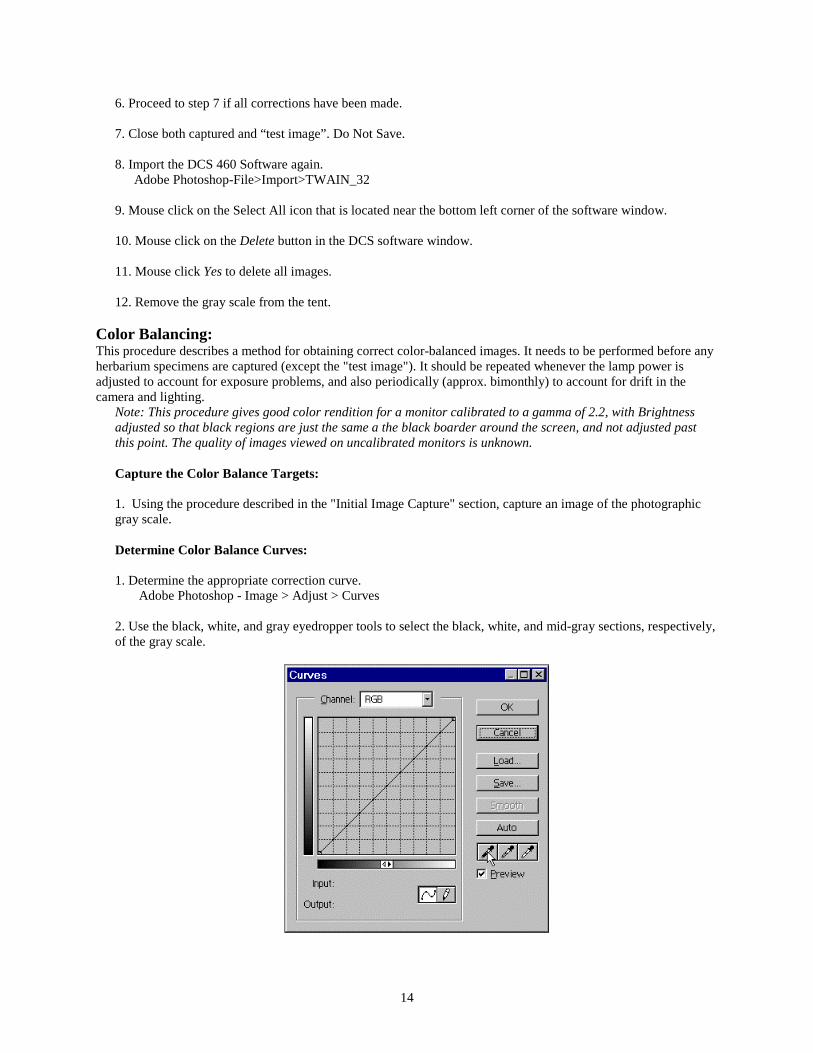
1. Determine the appropriate correction curve.Adobe Photoshop - Image > Adjust > Curves
2. Use the black, white, and gray eyedropper tools to select the black, white, and mid-gray sections, respectively,of the gray scale.

15
If the preview box is checked, the image patches should become neutral (no color tint), and approximatelyequally spaced visually from black to white.
3. Choose Save Curve…, and use the file browser to select the folder where the "create images" Action islocated. Mouse click save.
4. Select OK.
5. If the image boxes are not neutral a color balance adjustment should also be applied.Adobe Photoshop - Image > Adjust > Color balance…
6. Apply the correct color balance levels to each of the highlights, midtones, and shadows to make the imagepatches neutral on the gray scale.
Note: This should be checked by dragging the pointer over the gray scale and observing the RGB values inthe info palette. If the color balance is effective, all the numbers should be equal (± 2-3).
7. Record these values and select Cancel.
8. Undo the Curves adjustment in the History palette.
Add Curves to the "Create Images" Action:In order for this color balance adjustment to be applied to future captured images, it must be added to the "createimages" Action. Load the action as described on in the "Computer" section, Part 1.
1. Choose Start Recording from the Actions pull-down menu.
2. Apply the curves you just made to the color balance target image.Adobe Photoshop - Image > Adjust > Curves

16
Select Load Curves… and use the file browser to select the curves you just created. Press Load to select thecurves. Press "OK" to apply them.
3. Press Stop Recording in the Actions pull-down menu.
4. Delete the existing curves action (located below the Quantum Mechanic action) by dragging (click and holdon the mouse button on top of the line that says "Curves") the action to the trash bin at the bottom of the actionspalette (or by selecting delete from the actions pull down menu).
5. Drag (click and hold on the mouse button) the new Curves Action that you just recorded at the top of the listto just below Quantum Mechanic (TM), where the previous Curves Action was located.
6. Double click the "Color Balance" action and enter the values that you recorded in the previous section.
Imaging:The imaging process can only be performed after all equipment and specimen preparations have been completed.Refer to the “Initial Image Capture” or equipment manuals if there are questions concerning the Imaging process. The complete imaging process is carried out in three steps: 1) images are acquired through the camera and savedon the PCMCIA card, 2) images are transferred to the computer and renamed and, 3) images are processed in AdobePhotoshop and saved. It is recommended that the specimens are imaged family by family. This organization shouldalso be reflected in the creation on CDs. Eighty-one specimens can be imaged on one 520 Megabyte PCMCIA card. The acquiring of the images willinitially take 2-3 hours. The imaging time will decrease with experience. These images will later be saved into theCD-ROM Assembly folder.
1. Place a specimen in the light tent within the four corners of the previously created grid. The end with the labelinformation should be nearest the side of the light tent with the neutral density filter.
2. Mouse click on the Shutter Release button.Note: One image will be displayed in the DCS software window. Images can also be captured by pressing theshutter release button on the camera. After the correct setup is familiar, it is recommended to capture imagesdirectly from the camera. This will save time between moving specimens and capturing the image.
3. Remove the previously imaged specimen from the tent.
4. Place the next specimen in the light tent.
5. Align the specimen edges with the grid.Note: The specimen must be aligned with the grid. An unaligned specimen will be cropped in the imaging area.
6. Close the tent door.
7. Mouse click on the Shutter Release button.Note: There are now two images displayed in the DCS software window.
8. Repeat steps 2 through 7 to continue imaging specimens.Note: The process of imaging can cease at any time. Go to “Computer Shutdown” on p. 2-23 for furtherinstructions if the process needs to be stopped.
9. Capture approximately 81 images on the card.Note: The 520 Megabyte card can hold a total of 81 images. The computer will produce a message when thecard is full.
10. Click Done in the DCS 460 software.

17
11. Turn the camera off and unplug the AC adapter.Note: The camera should be disconnected from the computer at this stage if the camera will not be operatedagain for several hours.
Image Transfer and Renaming:This section provides the necessary steps to transfer images from the PCMCIA card to the computer and renamingthese images. The Camera Bits Photo Mechanic software must be installed for the renaming action to work.
Acquiring:
1. Remove the PCMCIA card from the DCS 460 camera.Note: Do not remove the PCMCIA card if the camera’s busy light is on. Consult the camera’s manual forthis step.
2. Refer to the Microtech Card Reader manual for instructions to load the card into the card reader.
3. Copy the images from the PCMCIA card to computer: D:\Aquired Images
Renaming:Images will be renamed as a batch by using the predefined Adobe Photoshop Action "rename images". Thisbatch process will open all images in D:\Aquired Images, one image at a time, and prompt you for a file namebefore saving the images in D:\Named Images. At this stage the specimens that were just imaged should beavailable to review.
Note: images are opened by file name, starting with the lowest numbered file name (e.g. Dsc00010.tif). Ifduring the imaging process the counter on the camera rolled over from 99 to 01, images will be opened inthe order of 01(=Dsc00010.tif), 02(=Dsc00020.tif), … 99(=Dsc00990.tif). Therefore, if/when this occurs itshould be noted so that the appropriate specimen can be located when the image is renamed.
1. In Adobe Photoshop automate the renaming of a batch of images using the "rename files" action.Adobe Photoshop-File>Automate>Batch… set all options to correspond with the image below.

18
2. You should now see the first specimen imaged. Confirm this by looking at the original.
3. Rename the specimen appropriately. Specimen names will consist of 3 fields and the appropriate 3 characterextension. The first field contains one character; the abbreviation for the division code: v = vascular plant, f =fungi, m = moss, h = hepatic, l = lichen, a = algae. The second field contains three or more characters; the familynumber. The last field contains 8 characters; the specimen bar code number. For example: v-261-00010224.jpgrefers to the neotype specimen for Macleania pentaptera.
4. Confirm that Photoshop is selected as the file format and the "save thumbnail" and the "use lower caseextension" boxes are checked.
5. Mouse click Save to place the image into the “Named Images” folder.
6. You should now see the second specimen imaged. Confirm this by looking at the original. Repeat steps 3through 5 for all of the captured images.
Deleting:Note: Do not proceed until all of the images have been renamed and saved into the “Named Images” folder.Deleting images should always be done through the camera, not the PCMCIA card reader.
1. Place the PCMCIA card back into the camera
2. Open the DCS 460 software.Adobe Photoshop-File>Import>TWAIN_32Note: The DCS software will display the images on the PCMCIA card.
3. Mouse click on the Select All icon.
4. Mouse click on Delete.
5. Mouse click Delete in the program message.Note: The images can not be retrieved after they have been deleted.
6. Delete the images in D:/Acquired Images.
Image Processing:The images can be compressed, sharpened, and color corrected as the batch by using a predefined Adobe PhotoshopAction "create images". The Action should have been saved on the C: Drive in Part 1. The file can be found on thesupplied NYBG CD if needed. There can be no imaging or other computer actions performed on this work stationwhile the Action is running. It is recommended that that this action be run overnight.
1. Open the Actions window.Adobe Photoshop-Window>Show Actions
Note: If the Actions window is already open the menu will display Hide Actions. Do not choose Hide Actions.
2. Proceed to "Setting the Batch” section if the NYBG action is displayed in the action window, if not proceed to the"Computer" section in Part 1.
Setting the Batch:
1. Choose Batch from the Automate menu in the File pull down menu.Adobe Photoshop-File>Automate>Batch…
2. Select "NYBG Images" from the Set selection box.

19
3. Select "create images" from the Action selection box.
4. Select "folder" from the Source selection box
5. Mouse click on the Choose button below the source selection box.
6. Direct the dialog box to the “Named Images” folder on the D: drive.
7. Mouse click twice on the “Named Images” folder
8. Click OK in the dialog box.
9. Select "None" from the destination selection box.
Note: The Batch dialog box should now be set exactly as in the image below.
Processing:
1. Mouse click OK in the Batch dialog box to process the action.
Note: The Action will now be applied to all of the files in the “Named Images” folder and saved to the fourfolders designated in the "create images" action. It should take approximately 2 hours to run this action so itis recommended that the action be run overnight.
2. When the action is complete mouse click on the minimize application icon that is located at the upper right-hand corner of the Photoshop window.
3. Delete all files in the “Named Images” folder on the D: drive.
Image Archiving:
The CD ROM assembly folder is used for organizing specimen files before they are burned to a CD. A CD-ROMcan hold 650MB of data, equaling approximately 550 image files. Pay special attention to the amount of information

20
in a folder and do not let the information exceed 648MB per folder. Two copies of the CD's should be created; onefor the herbarium and another for the library.
CD's should be organized by family. Within a family it is recommended that genera not be split between twoCD's. See previously created CD's for examples. When the CD ROM assembly folder becomes full, the files shouldbe archived on to a CD. Only burn a CD when a folder is full, since a CD can be burned only once. After thearchiving process is completed, the files in the folder can be deleted and the CD-ROM assembly folder can onceagain be used for organizing sample files.
Similarly, once a family has been imaged its files should be moved from the "Web Images" and "WebThumbnails" to their own family subfolder in "Web Images - completed families" and "Web Thumbnails -completed families" respectively.
1. Organize the files throughout the CD ROM assembly folder in families.
Note: There will be approximately 150 CDs used to archive the 75,000 specimens. If one or more of the 75,000archived samples is needed, it is imperative that the files are organized in a manner that it can be accessedeasily.
2. Continue photographing specimens and organizing them in the folders until the folders contains approximately550 files that do not exceed 648MB.
Note: Return to step 4 on the “Imaging” section of the manual if a folder is not full. If one or more of the foldersare full, proceed in this section.
4. Launch the CD-R Writer application.
5. Follow the instructions in the CD-R Writer software manual for burning the two CDs. It is recommended that a"disk image" be made of the files to facilitate the creation of both CDs.
6. Load the burned CDs into the computer’s CD-ROM drive.
7. Check the burned CDs to insure all files were transferred from the folder to the CD.
8. Mouse click twice on a file to make sure that it will open into Adobe Photoshop.
9. Close the file if it opened.
10. Refer to the CD-R Writer manual if problems occur.
11. Proceed only if the CDs were burned correctly.
12. Delete the files from the CD-ROM Assembly folder that were burned to the CD.
Note: After a folder of images is burned, the images must be deleted to open hard drive space for future imagefiles.
Printing:
The process of printing images takes approximately five minutes per image. All appropriate actions and colorcorrections must be performed before this step. This printer should be properly set up and calibrated beforeproceeding.
1. Open the image to be printed in Adobe Photoshop.
2. Select File>Export>Kodak 8670 Printer…

21
3. Select the appropriated setting in the printer menu and click OK
Shutdown:
The shutdown process should be done at the end of every workday to prolong equipment life. It is not necessary toshut down the system if the archiving process is temporarily going to cease. These steps are to only be performedafter all current computer and camera functions have been completed.
1. Turn the camera off.
2. Unplug the AC adapter from the camera.
3. Turn the strobe power pack off.
4. Shutdown the computer.
Note: If the computer is to be used without the camera, be sure to disconnect the SCSI cable from the back of thecomputer so that the camera batteries are not drained.

22
Suggested Equipment Vendors and Approximate Pricesfor the Digital Photography System
Part 3
Note: These prices and vendors are subject to change. Shipping prices are not included.
B&H Photographic420 Ninth AvenueNew York, New York 100011-800-947-9980 or (212) 444-6666www.bhphotovideo.com
Camera:• Kodak DCS660 Professional Digital Camera $20,000.00• 60mm Micro Nikkor lens f2.8 $340.00• 62mm HN-22 Lens Hood $22.00• Nikon DR-3 Right Angle Finder $80.00• Nikon DK-7 Eyepiece Adapter $2.00• 2 Type III PCMCIA cards (1 Gigabyte) $500.00 each
Note: the Callunacards are not recommended, but may be the only choice. If a Callunacard is purchased, itshould be the 521 or the 1040. The most reliable cards are the Viper cards that come in 340 Megabytes andsmaller. Consult Rob Galbraith's web site (http://www.robgalbraith.com/diginews/) for up-to-dateinformation on this technology.
Printer:
• Kodak 8700 Printer $7000.00• Paper (8 1/2x11, 100 sheets) $58.50• Ribbon (CMYK recommended) $120.00
UV protectant, color, 2per box, 100 prints per ribbonNote: Specify the 8.5" wide adjustable tray.
Copy Stand:• Bencher Copystand $1946.50
model #500-55 “Quartz Halogen Floor Producer”
Strobe Kit:• Speedotron-Black Line
quantity: 1. 805 Power Pack $635.002. 102 Flash Heads $285.00 each2. 11.5 inch Reflectors $25.00 each2. 2 Way Barn Doors $40.00 each
• Bogenquantity 2. 3330 6’ Basic Light Stand $38.00 each
Accessories:• 3 Neutral density sheets (approx. 60 x 60 cm) $20.00• Black velvet sheet (approx. 80 x 80 cm) $10.00• Black cloth (from darkroom dept.) (1 roll - 2' x 16') $10.00

23
• 15' Household to PC cord (Paramount #2-15S) $8.00• Spirit level $20.00• Black foam core board (approx. 4' x 4')' $5.00• Photographic gray scale $30.00
Calumet Photographic11 W. 20th St., 4th fl.New York, New York 100111-800-225-8638 or (212) 989-8500
Light Tent:• Balcar Light Pyramid 71 $225.00Note: This light tent is the ideal size for a herbarium sheet, but too large for the copystand. A black piece ofplywood, approx. 74 x 74 cm (29" x 29") should be attached the copystand surface to accommodate this lighttent.
Sony direct on-line store (http://vaiodirect.sel.sony.com/)
Monitor:• Sony CPD-500PS (21 inch Monitor) $1,200.00
Z-Source (http://www.zsource.com/pioneer/optical.htm)
• Pioneer DVD-R drive $5,400.00
Dell Computer 1-800-WWW-DELL• Dell Workstation 420 Minitower
-866 MHz Pentium III Processor-512 Megabyte of ECC RAM (3 DIMMs)-first hard drive: 36 Gigabyte SCSI hard drive (10,000 RPM) with Adaptec 2940UW SCSI Controller-second hard drive: 9 Gigabyte SCSI hard drive (10,000 RPM)
-32 Megabyte Matrox G400 Video Card-40x SCSI CD-ROM Drive-IEEE 1394 Controller Card-3Com 3C905-TX 10/100 Network Card-Microsoft Windows 98 Second edition (CD)-Microsoft System Mouse-1.44 Megabyte Floppy Drive-Spacesaver 104-Key Windows 95 Keyboard-1 year of Windows 98 Support-3 year, next business day, on site service
Total Computer Price $4,400.00
recommended upgrade: The fastest computer affordable is always recommended as the computer is alimiting factor in the processing of images. One way to increase CPU power would be to run Windows NT or2000 with dual processors. This would necessitate purchasing software and hardware (where applicable) forthe Windows NT operating system.
Microtech 1-800-626-4276 (Louis Modell)

24
Card Reader:• Internal PCMCIA Card Reader $349.00Part#: DPA-SCSI-PC (For Window 98)
Cyber Connection 714-475-9100
SCSI Cable:• DVD-R Writer to printer SCSI cable. $80.00
Lightning Powder Company , INC.1230 Hoyt Street, South EastSalem, Oregon 97302-21211-800-852-0300 or (503) 585-9900
Imaging Scales:• Adhesive Scales $4.50 (50 Scales)
Black Scales with White PrintingCatalog#6-3848
Camera Bits3705 NW Columbia Ave.Portland, OR 97229503-531-8430http://www.camerabits.com/
Software:• Quantum Mechanic $179.00• Photo Mechanic $295.00
Local Stores:
Misc.
• Adobe Photoshop (latest version) $600.00• DVD-R Media $160.00• UPS battery backup system $600.00• Barcode reader $600.00• Black Duct tape $5.00
Lizard Techwww.lizardtech.com
• MrSID Desktop Encoder $1350• Gold technical server support (per year) $270