高等軟體設計 nccu cs lecture 3 fall 2005 sept. 27, 2005
Post on 21-Dec-2015
251 views
TRANSCRIPT
高等軟體設計NCCU CS
Lecture 3Fall 2005
Sept. 27, 2005
Topics
• The Big Picture: Software Development Process
• Requirement Analysis and Specification• UML Overview• Class Diagrams• Sequence Diagrams
Software Process
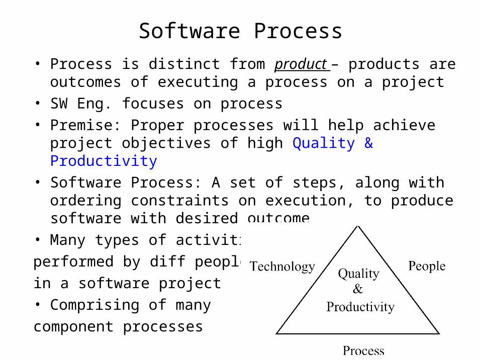
• Process is distinct from product – products are outcomes of executing a process on a project
• SW Eng. focuses on process• Premise: Proper processes will help achieve project
objectives of high Quality & Productivity• Software Process: A set of steps, along with ordering
constraints on execution, to produce software with desired outcome
• Many types of activities
performed by diff people
in a software project• Comprising of many
component processes

Component Processes• Two major processes
– Development – focuses on development and quality steps needed to engineer the software
– Project management – focuses on planning and controlling the development process
• Development process is the heart of software process; other processes revolve around it
• These are executed by different people– developers execute development process– project manager executes the mgmt process
• Other processes:– Configuration management process: manages the evolution of
artifacts– Change management process: how changes are incorporated– …
A process defines Who is doing What When, and How, in order to reach a certain goal.
Major Activities (Steps) in SW Development Process
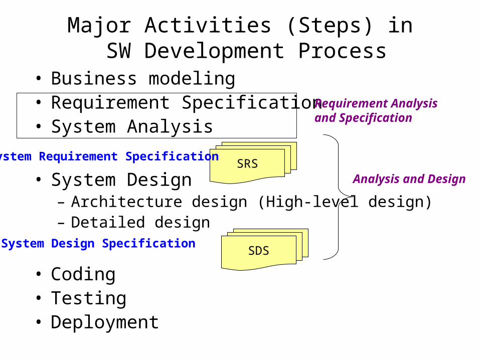
• Business modeling• Requirement Specification• System Analysis
• System Design– Architecture design (High-level design)– Detailed design
• Coding• Testing• Deployment
SRSSystem Requirement Specification
SDSSystem Design Specification
Requirement Analysis and Specification
Analysis and Design
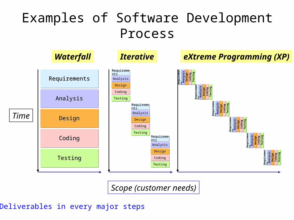
Examples of Software Development Process
RequirementsRequirementsRequirementsRequirements
AnalysisAnalysisAnalysisAnalysis
DesignDesignDesignDesign
CodingCodingCodingCoding
TestingTestingTestingTesting
Time
RequirementsRequirementsRequirementsRequirements
AnalysisAnalysisAnalysisAnalysis
DesignDesignDesignDesign
CodingCodingCodingCoding
TestingTestingTestingTesting
RequirementsRequirementsRequirementsRequirements
AnalysisAnalysisAnalysisAnalysis
DesignDesignDesignDesign
CodingCodingCodingCoding
TestingTestingTestingTesting
RequirementsRequirementsRequirementsRequirements
AnalysisAnalysisAnalysisAnalysis
DesignDesignDesignDesign
CodingCodingCodingCoding
TestingTestingTestingTesting
Scope (customer needs)R
equ
irem
ents
Req
uir
emen
ts
An
alys
isA
nal
ysis
Des
ign
Des
ign
Cod
ing
Cod
ing
Tes
tin
gT
esti
ng
Req
uir
emen
tsR
equ
irem
ents
An
alys
isA
nal
ysis
Des
ign
Des
ign
Cod
ing
Cod
ing
Tes
tin
gT
esti
ng
Req
uir
emen
tsR
equ
irem
ents
An
alys
isA
nal
ysis
Des
ign
Des
ign
Cod
ing
Cod
ing
Tes
tin
gT
esti
ng
Req
uir
emen
tsR
equ
irem
ents
An
alys
isA
nal
ysis
Des
ign
Des
ign
Cod
ing
Cod
ing
Tes
tin
gT
esti
ng
Req
uir
emen
tsR
equ
irem
ents
An
alys
isA
nal
ysis
Des
ign
Des
ign
Cod
ing
Cod
ing
Tes
tin
gT
esti
ng
Req
uir
emen
tsR
equ
irem
ents
An
alys
isA
nal
ysis
Des
ign
Des
ign
Cod
ing
Cod
ing
Tes
tin
gT
esti
ng
Waterfall Iterative eXtreme Programming (XP)
Deliverables in every major steps
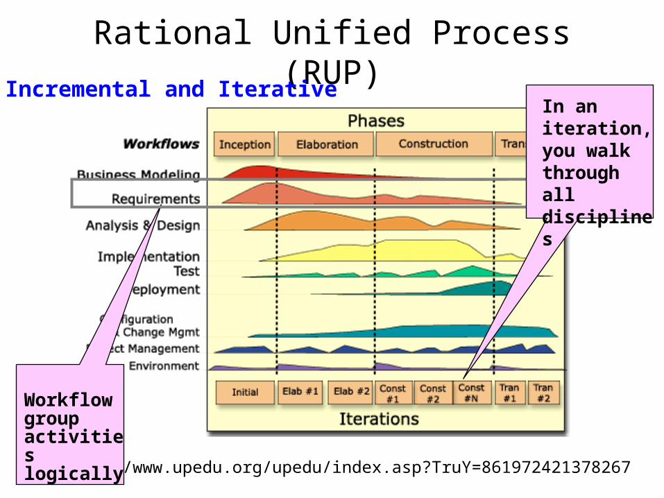
Rational Unified Process (RUP)
http://www.upedu.org/upedu/index.asp?TruY=861972421378267
Workflow group activities logically
In an iteration, you walk through all disciplines
Incremental and Iterative
Requirements: Analysis, Specification, Management

Requirement ElicitationAnalyzing the problem
The notion that we find out what users need by simply asking them is NOT true.

WANT: local user
domain knowledge
NEED: global user domain knowledge
CAN-DO: design expert domain
knowledge
Requirement Requirement SpecificationSpecification
Deep Structure of Requirements
Not all that you hear, should be implemented; and not all that is implemented, is needed.

Stakeholder Needs(extracted from the slides of Peter Hauker, Rational)
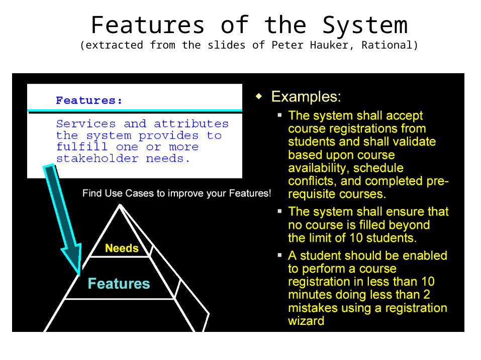
Features of the System(extracted from the slides of Peter Hauker, Rational)

Software Requirements(extracted from the slides of Peter Hauker, Rational)
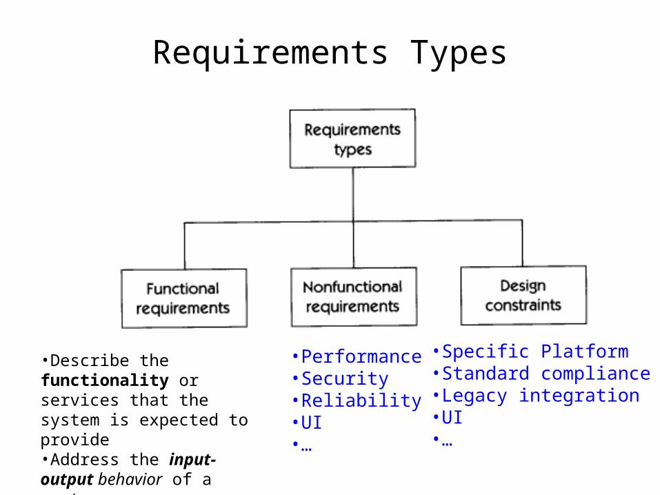
Requirements Types
•Performance•Security•Reliability•UI•…
•Specific Platform•Standard compliance•Legacy integration•UI•…
•Describe the functionality or services that the system is expected to provide •Address the input-output behavior of a system
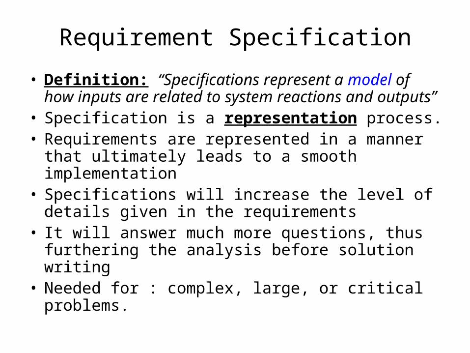
Requirement Specification
• Definition: “Specifications represent a model of how inputs are related to system reactions and outputs”
• Specification is a representation process. • Requirements are represented in a manner that
ultimately leads to a smooth implementation• Specifications will increase the level of details
given in the requirements• It will answer much more questions, thus
furthering the analysis before solution writing• Needed for : complex, large, or critical problems.
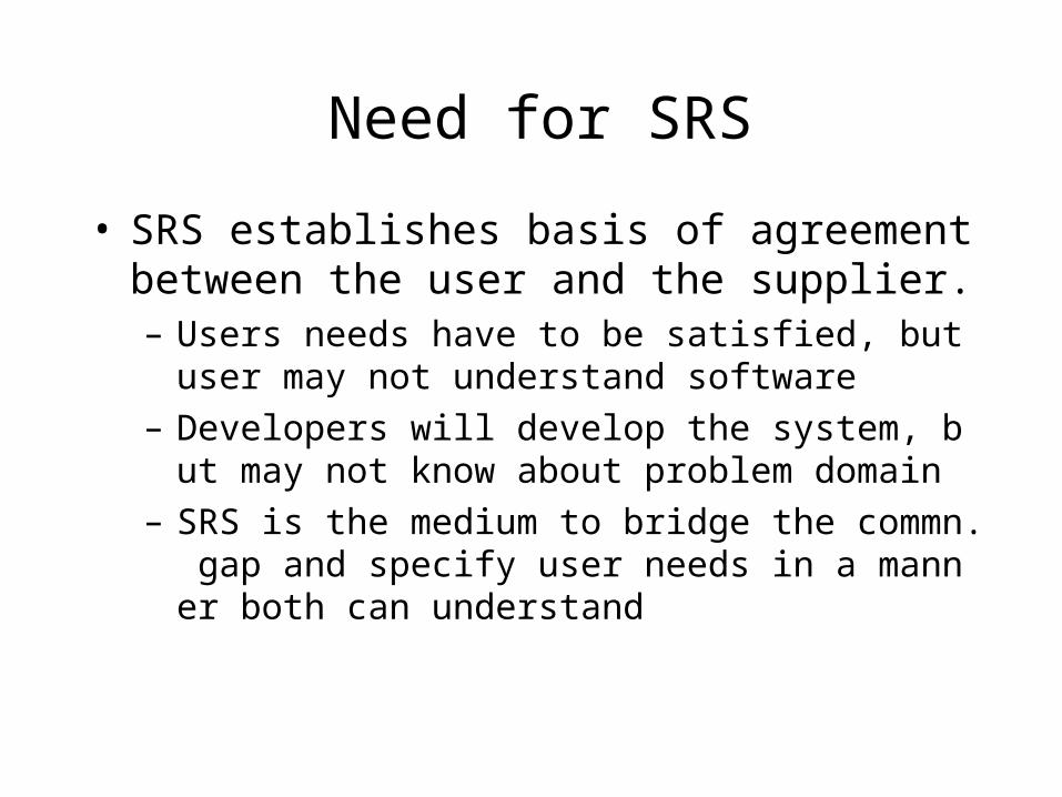
Need for SRS
• SRS establishes basis of agreement between the user and the supplier.– Users needs have to be satisfied, but user may not
understand software– Developers will develop the system, but may not k
now about problem domain– SRS is the medium to bridge the commn. gap and
specify user needs in a manner both can understand

Characteristics of a Good SRS
• Correct• Complete• Unambiguous• Consistent• Verifiable• Traceable• Modifiable• Ranked for importance and/or stability

Requirement Specifications seldom clearly capture customer needs
What user wanted How customer described it How analyst specified it How designer implemented it
Don't Gather Requirements—Dig for Them

Specification Languages
• Natural languages mostly used, with some structure for the document– Carry lot of noise, ambiguities, and contradictions– Hard to analyze– Example: Signs Displayed at the Foot of an Escalator in an Airport
• Formal languages are precise and unambiguous but hard
• Formal languages used for special features or in highly critical systems
Shoes Must Be Worn
Dogs Must Be Carried
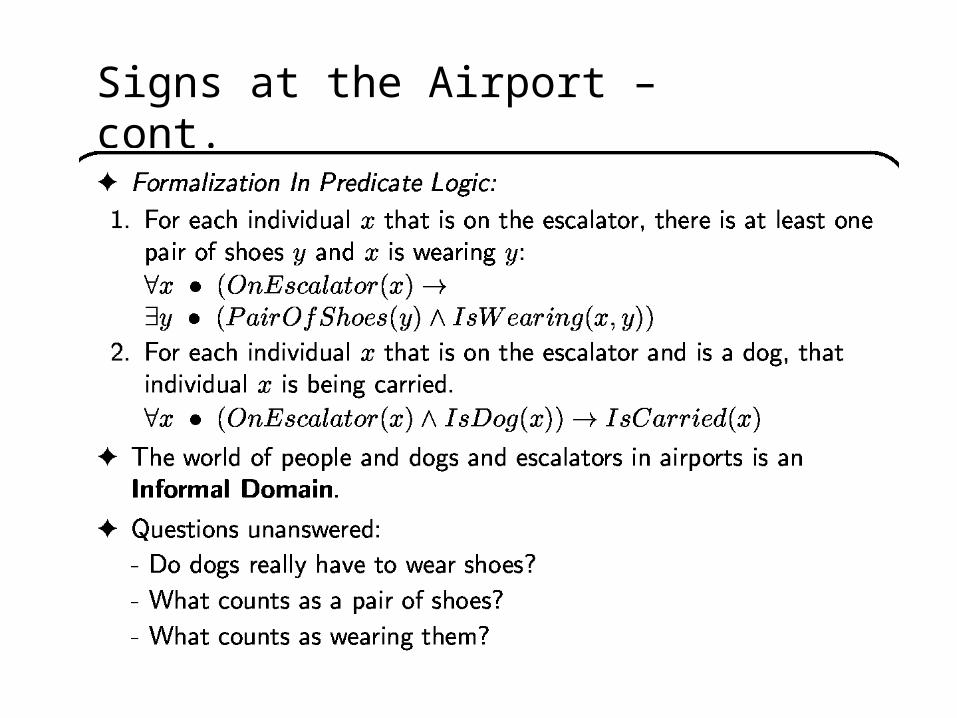
Signs at the Airport – cont.
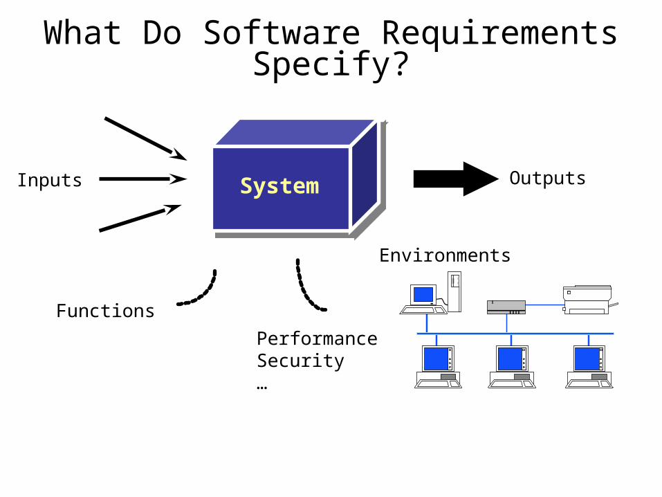
What Do Software Requirements Specify?
SystemInputs Outputs
Functions
PerformanceSecurity…
Environments
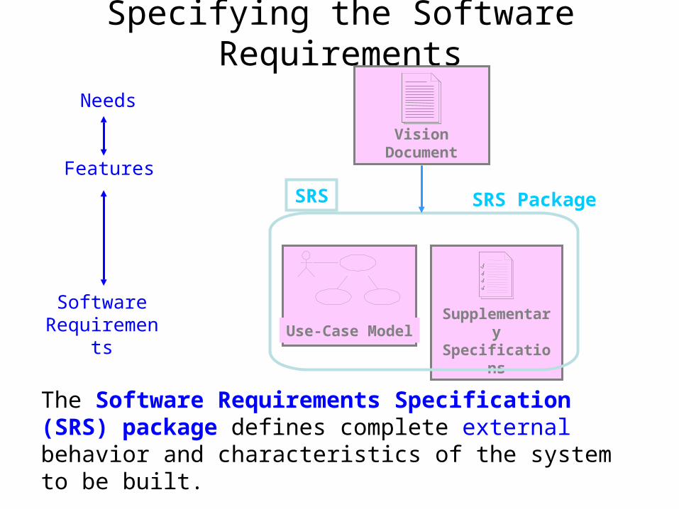
Specifying the Software Requirements
Features
SoftwareRequirements
Needs
The Software Requirements Specification (SRS) package defines complete external behavior and characteristics of the system to be built.
Vision Document
Supplementary SpecificationsUse-Case Model
SRS SRS Package
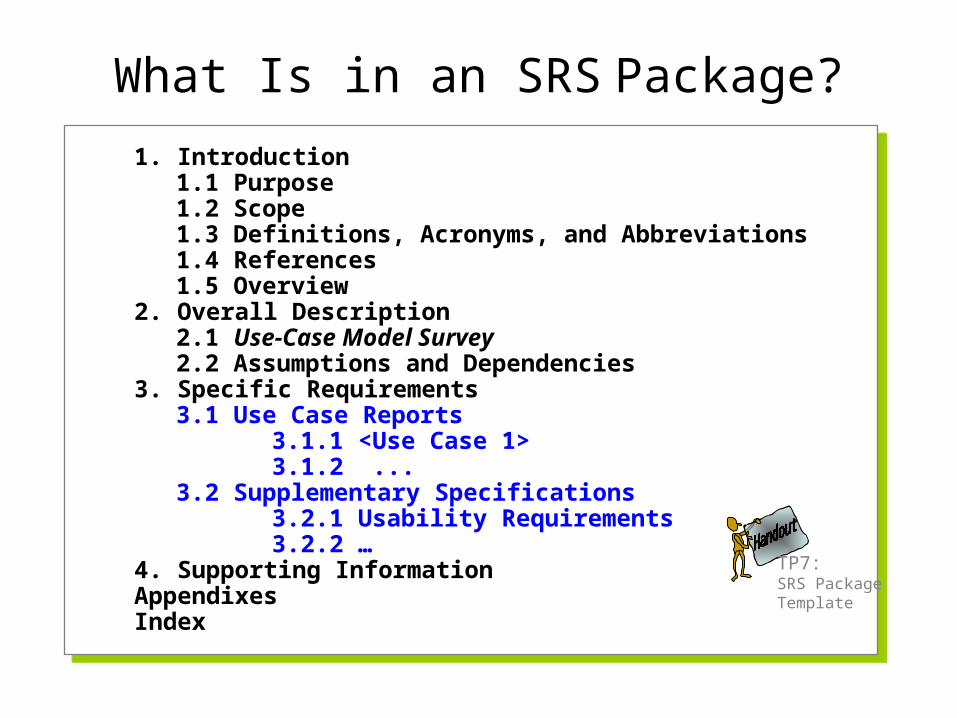
1. Introduction1.1 Purpose1.2 Scope1.3 Definitions, Acronyms, and Abbreviations1.4 References1.5 Overview
2. Overall Description2.1 Use-Case Model Survey2.2 Assumptions and Dependencies
3. Specific Requirements3.1 Use Case Reports
3.1.1 <Use Case 1>3.1.2 ...
3.2 Supplementary Specifications3.2.1 Usability Requirements3.2.2 …
4. Supporting InformationAppendixesIndex
What Is in an SRS Package?
TP7: SRS Package Template

Use Case Approach to Modeling Functional Requirements
Build a Use Case Model
Use cases document the behavior of the system from the users’ point of view.

A Use-Case Model Contains Diagrams and Text
Use-Case-Model Survey- survey description - list of all actors- list of all use cases
Use Case 2 Report- brief description- flow of events
Use Case 3 Report- brief description- flow of events
Actor 1
Use Case 2
Use Case 3
The System
Use Case 1
Actor 2
Actor 3
Use Case 1 Report- brief description - flow of events
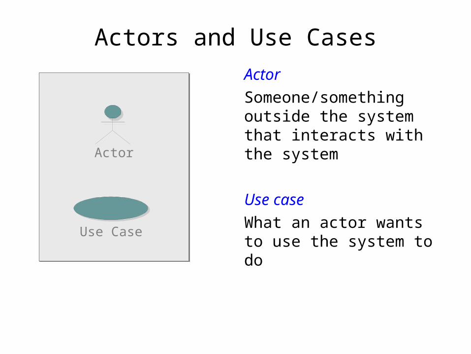
Actors and Use Cases
Actor
Someone/something outside the system that interacts with the system
Use case
What an actor wants to use the system to do
Actor
Use Case

Communicates-Association
• A channel of communication between an actor and a use case
• A line is used to represent it• An arrow indicates who
initiates the communication
Actor 1
Use Case
Actor 2

Use-Case Diagram
Bank Consortium
Bank Customer
Deposit Funds
Withdraw Cash
An Automated Teller Machine (ATM)
Transfer Funds
Cashier
Maintain ATM
MaintenanceCrew
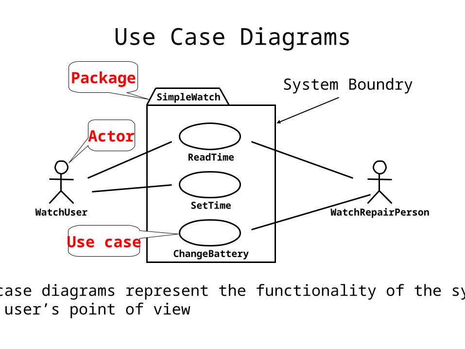
Use Case Diagrams
WatchUser WatchRepairPerson
ReadTime
SetTime
ChangeBattery
Actor
Use case
PackageSimpleWatch
Use case diagrams represent the functionality of the systemfrom user’s point of view
System Boundry

Documenting Use Cases
Use case: Place OrderActors: CostumerPrecondition: A valid user has logged into the systemFlow of Events:
1. The use case begins when the customer selects Place Order2. The customer enters his or her name and address3. If the customer enters only the zip code, the system supplies the city and state4. The customer enters product codes for products to be ordered5. For each product code entered
a) the system supplies a product description and priceb) the system adds the price of the item to the total
end loop6. The customer enters credit card payment information7. The customer selects Submit8. The system verifies the information [Exception: Information Incorrect], saves the order as pending, and forwards payment information to the accounting system. 9. When payment is confirmed [Exception: Payment not Confirmed], the order is marked confirmed, an order ID is returned to the customer, and the use case terminates
Exceptions: Payment not Confirmed: the system will prompt the customer to correct payment information or cancel. If the customer chooses to correct the information, go back to step 6 in the Basic Path. If the customer chooses to cancel, the use case terminates.
Information Incorrect: If any information is incorrect, the system prompts the customer to correct it.Postcondition: If the order was not canceled, it is saved in the system and marked confirmed
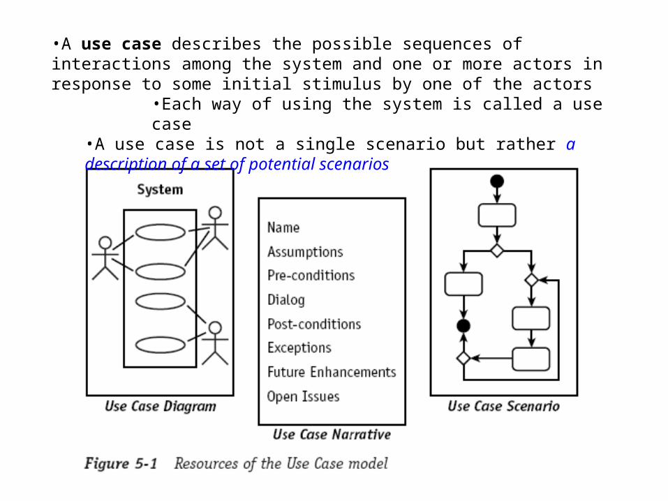
•A use case describes the possible sequences of interactions among the system and one or more actors in response to some initial stimulus by one of the actors
•Each way of using the system is called a use case•A use case is not a single scenario but rather a description of a set of potential scenarios
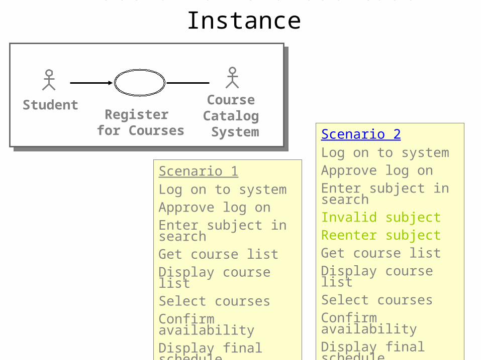
A Scenario Is a Use-Case Instance
Scenario 1Log on to systemApprove log onEnter subject in searchGet course listDisplay course listSelect coursesConfirm availabilityDisplay final schedule
Scenario 2Log on to systemApprove log onEnter subject in searchInvalid subjectReenter subject Get course listDisplay course listSelect coursesConfirm availabilityDisplay final schedule
Student Course Catalog System
Register for Courses
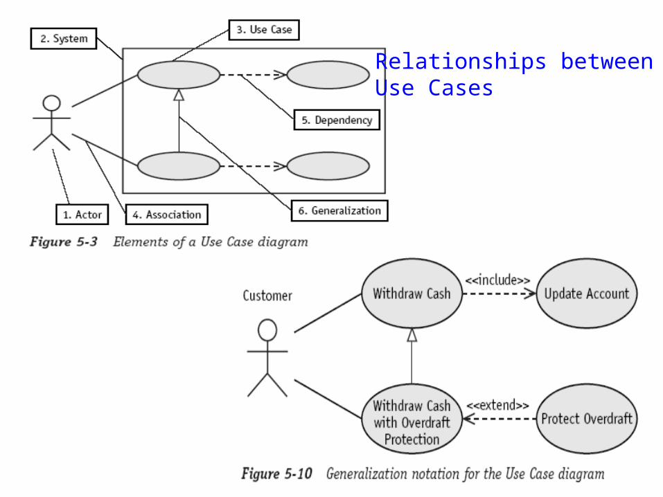
Relationships between Use Cases
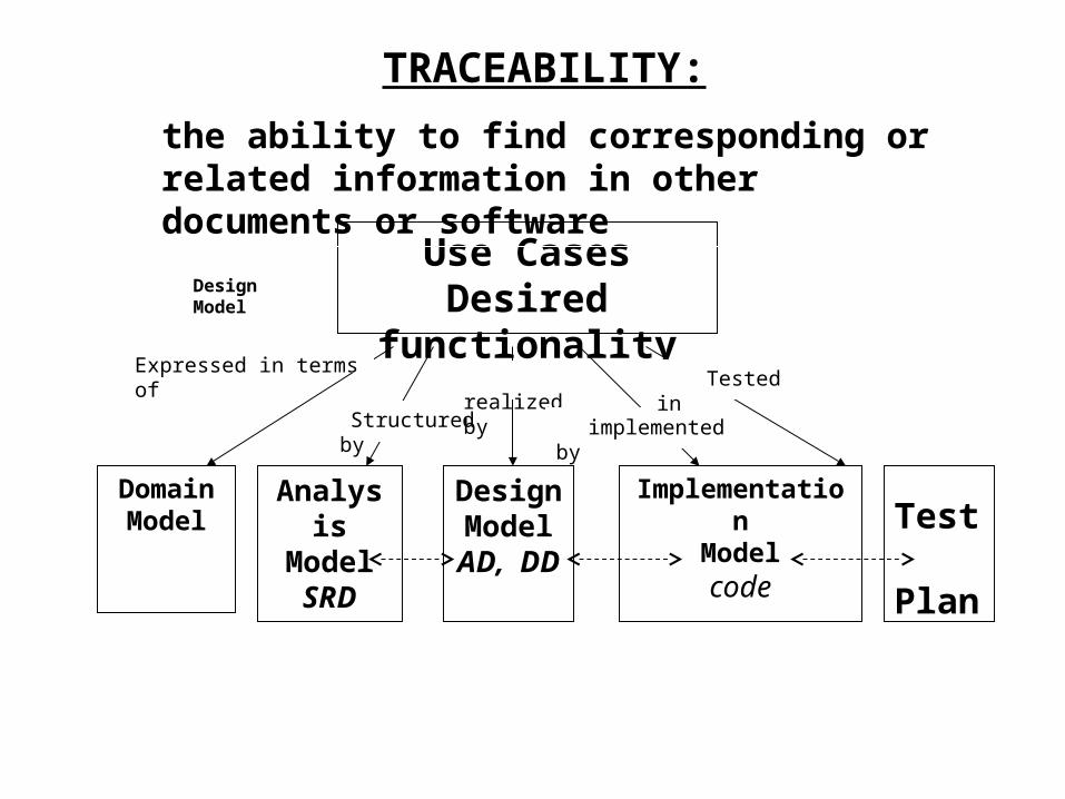
Use CasesDesired functionality
DomainModel
Design Model
AD, DD
Implementation
Modelcode
Test Plan
Analysis ModelSRD
Expressed in terms of
Structured by
realized by
implemented by
Tested in
DesignModel
TRACEABILITY:
the ability to find corresponding or related information in other documents or software

Levels of Testing
User needs Acceptance testing
Requirementspecification
System testing
Design
code
Integration testing
Unit testing

Find Actors and Use Cases
• Identify actors• Describe actors• Identify use cases• Describe use cases briefly• Identify actor and use case relationships • Make use-case diagrams• Outline use cases
Use Cases have become part of the UML.
The UML is
• The language of blueprints for software• A graphical language for
– visualizing– specifying– constructing– documenting
the artifacts of a software-intensive system.
(code & document)
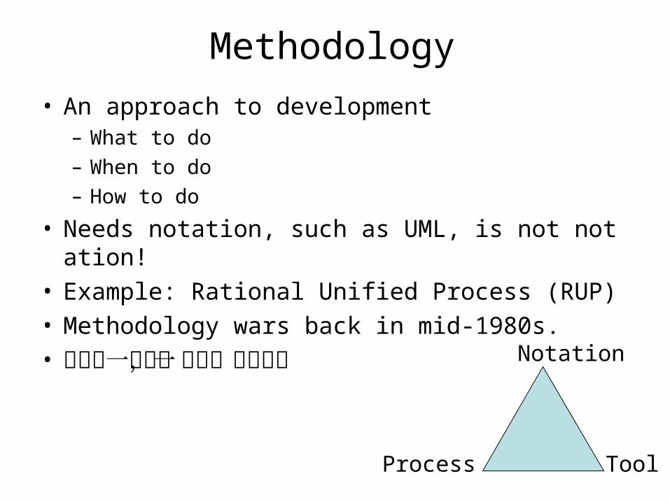
Methodology
• An approach to development– What to do– When to do– How to do
• Needs notation, such as UML, is not notation!• Example: Rational Unified Process (RUP)• Methodology wars back in mid-1980s.• 不能統一方法,先統一表達方式
Process Tool
Notation
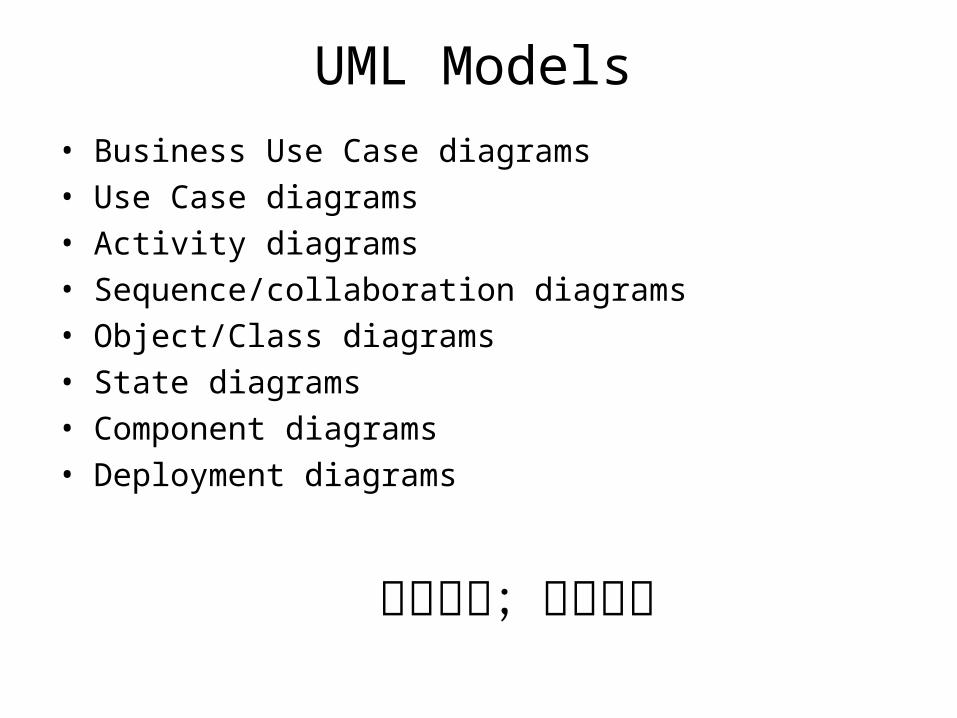
UML Models
• Business Use Case diagrams• Use Case diagrams• Activity diagrams• Sequence/collaboration diagrams• Object/Class diagrams• State diagrams• Component diagrams• Deployment diagrams
捕捉需求;表達設計

Visual Modeling Using UML Diagrams
Actor A
Use Case 1
Use Case 2
Actor B
user : Clerk
mainWnd : MainWnd
fileMgr : FileMgr
repository : Repositorydocument : Document
gFile : GrpFile
9: sortByName ( )
L1: Doc view request ( )
2: fetchDoc( )
5: readDoc ( )
7: readFile ( )
3: create ( )
6: fillDocument ( )
4: create ( )
8: fillFile ( )
Window95
¹®¼ °ü¸®
Ŭ¶óÀ̾ðÆ®.EXE
Windows
NT
¹®¼ °ü¸® ¿£Áø.EXE
WindowsNT
Windows95
Solaris
ÀÀ¿ë¼ ¹ö.EXE
AlphaUNIX
IBM
Mainframe
µ¥ÀÌŸº£À̽º¼ ¹ö
Windows95
¹®¼ °ü¸® ¾ÖÇø´Document
FileManager
GraphicFile
File
Repository DocumentList
FileList
user
mainWnd fileMgr : FileMgr
repositorydocument : Document
gFile
1: Doc view request ( )
2: fetchDoc( )
3: create ( )
4: create ( )
5: readDoc ( )
6: fillDocument ( )
7: readFile ( )
8: fillFile ( )
9: sortByName ( )
ƯÁ¤¹®¼ ¿¡ ́ ëÇÑ º¸±â¸¦ »ç¿ëÀÚ°¡ ¿äûÇÑ´Ù.
È ÀÏ°ü̧ ®ÀÚ´Â Àоî¿Â ¹®¼ ÀÇ Á¤º¸¸¦ ÇØ´ç ¹®¼
°´Ã¼¿¡ ¼³Á¤À» ¿äûÇÑ´Ù.
È ̧é °´Ã¼´Â ÀоîµéÀÎ °´Ã¼µé¿¡ ´ëÇØ ÀÌ̧ §º°·Î
Á¤·ÄÀ» ½ÃÄÑ È ̧é¿¡ º¸¿©ÁØ´Ù.
Forward and Reverse Engineering
TargetSystem
Openning
Writing
ReadingClosing
add file [ numberOffile==MAX ] / flag OFF
add file
close file
close fileUse Case 3
Use-casediagram Class diagram
Collaboration diagram
Sequence diagram
Component diagram
Statechartdiagram
GrpFile
read( )open( )create( )fillFile( )
rep
Repository
name : char * = 0
readDoc( )readFile( )
(from Persistence)
FileMgr
fetchDoc( )sortByName( )
DocumentList
add( )delete( )
Document
name : intdocid : intnumField : int
get( )open( )close( )read( )sortFileList( )create( )fillDocument( )
fList
1
FileList
add( )delete( )
1
File
read( )
read() fill the code..
Deployment diagram

Modeling: From Requirements To Solution
• Modeling a system involves:– identifying the things that are important to your
particular view – Their structures and properties– consider how specific instances of these things
must fit together (interaction).
• Modeling a system is affected by how you expect to use the system

A Simple Example: Dice Game
• Requirements is the Starting Point (WHAT, i.e., problem oriented)
Dice Game:• A player rolls two dice. If the total is seven, the player wins; otherwise he loses.

SE: Dice Game
• Solution
Dice Game:• Roll two dice.
CONGRATULATIONS! You won the game.

SE: Dice Game
• Modeling Features:
Dice Game:• A player rolls two dice. If the total is seven, the player wins; otherwise he loses.
Play with one user and two dice
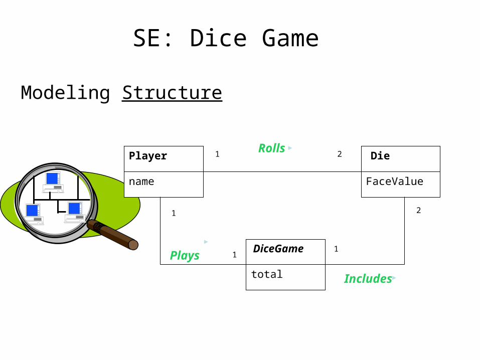
SE: Dice Game
Modeling Structure
Player
name
Die
FaceValue
DiceGame
total
Rolls1 2
1
1
Plays1
2
Includes

SE: Dice Game
Modeling Behavior: DiceGame
Die1: Die
Die2:Die
Play()
GetFaceValue()
roll()
roll()
GetFaceValue()
Total() Result()
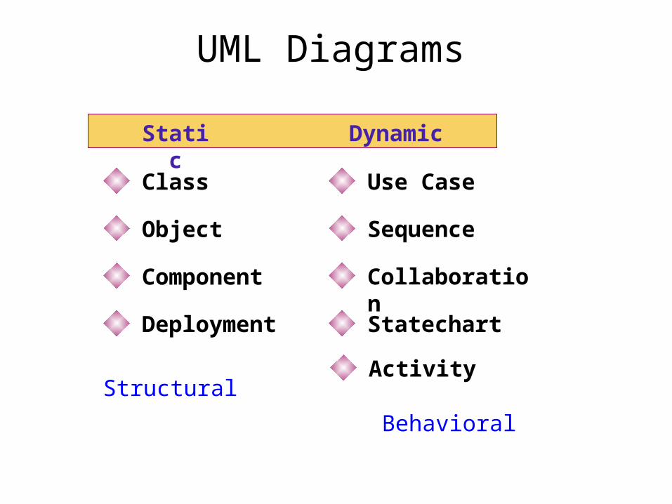
UML Diagrams
Static Dynamic
Class
Object
Component
Deployment
Use Case
Sequence
Collaboration
Statechart
ActivityStructural
Behavioral

OOA Using UML: Overview
• Requirements elicitation– Use case diagrams
• Requirements analysis– Class diagrams– Sequence diagrams– State diagrams– Activity diagrams
• Requirements verification and validation– We will discuss it later
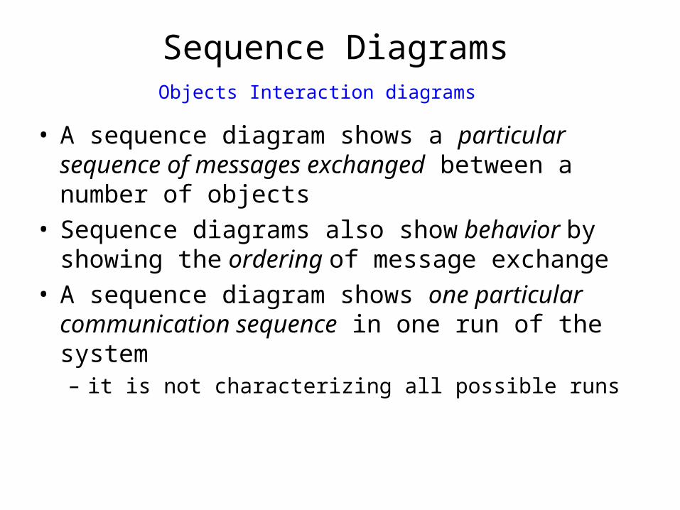
Sequence Diagrams
• A sequence diagram shows a particular sequence of messages exchanged between a number of objects
• Sequence diagrams also show behavior by showing the ordering of message exchange
• A sequence diagram shows one particular communication sequence in one run of the system – it is not characterizing all possible runs
Objects Interaction diagrams
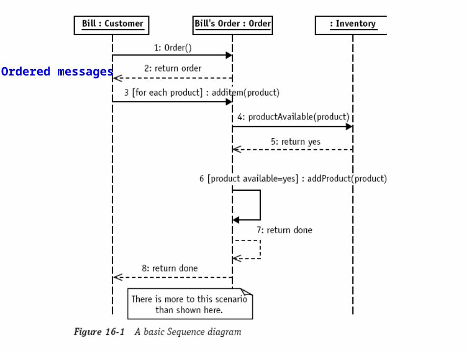
Ordered messages
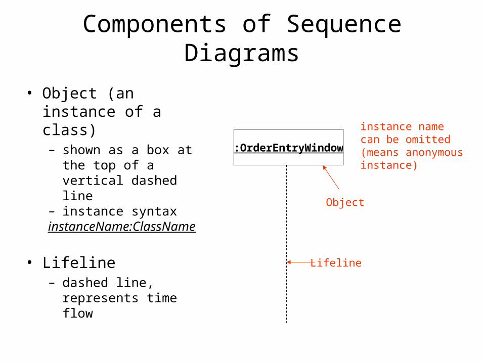
Components of Sequence Diagrams
• Object (an instance of a class)– shown as a box at the
top of a vertical dashed line
– instance syntaxinstanceName:ClassName
• Lifeline– dashed line, represents
time flow
:OrderEntryWindow
instance namecan be omitted(means anonymous instance)
Object
Lifeline

Components of Sequence Diagrams
• Messages– communication between
objects– method calls at the
implementation level
• Special message types– self-delegation– return
• show returns only if it adds to clarity
– <<create>>– <<destroy>>
:ProductOrder
Return
:StockItem
Message
Self-delegation
check()
needsToReorder()
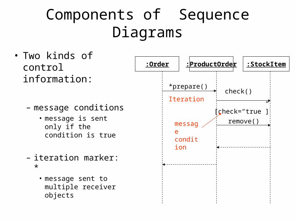
Components of Sequence Diagrams
• Two kinds of control information:
– message conditions• message is sent only
if the condition is true
– iteration marker: *• message sent to
multiple receiver objects
:ProductOrder :StockItem
check()
:Order
*prepare()
Iteration
[check=“true”]
remove()messagecondition
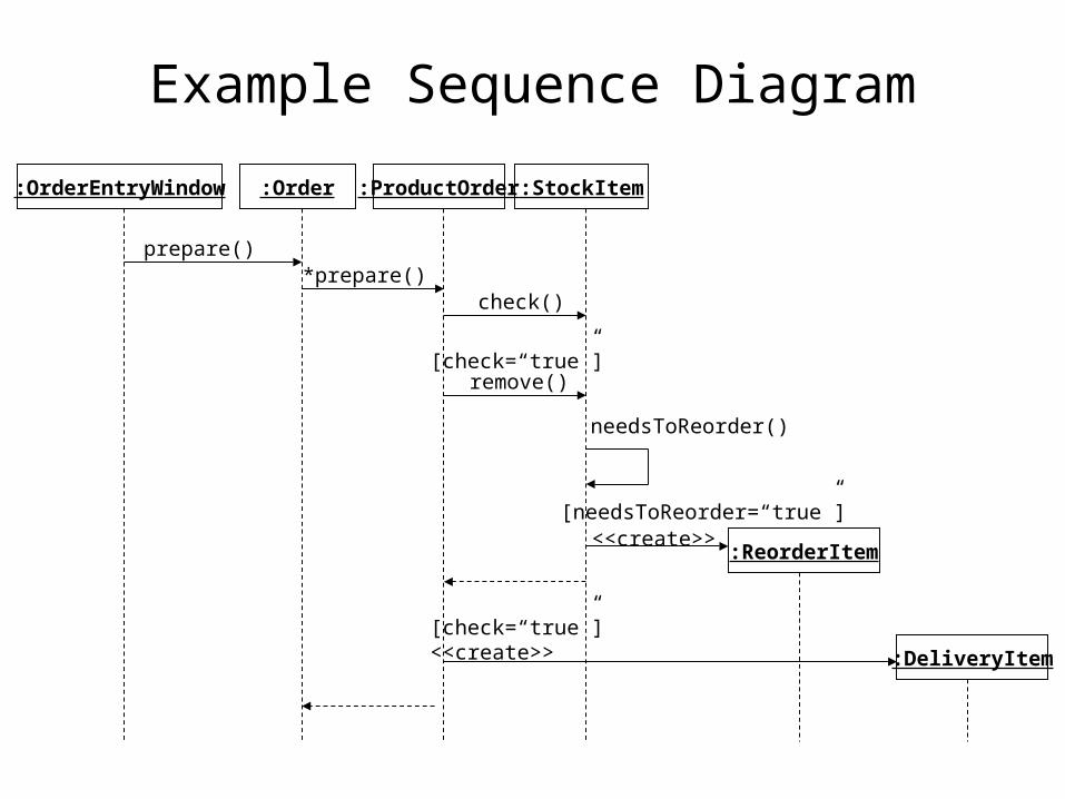
Example Sequence Diagram
:ProductOrder :StockItem
check()
:Order
*prepare()
[check=“true”]remove()
:OrderEntryWindow
prepare()
:ReorderItem
:DeliveryItem
needsToReorder()
<<create>>
[check=“true”]<<create>>
[needsToReorder=“true”]
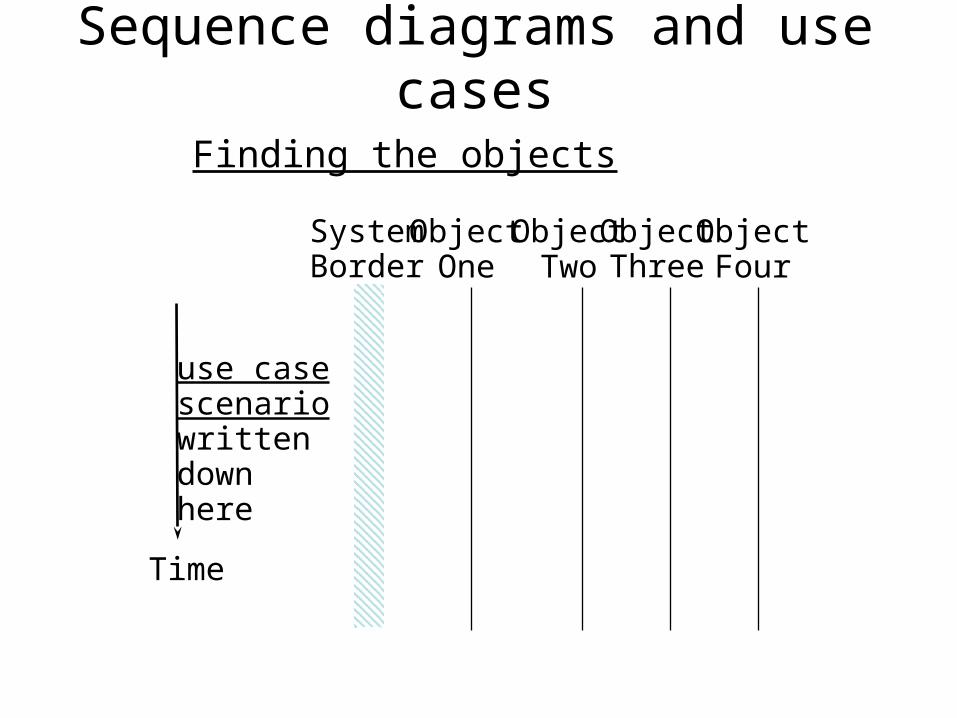
Sequence diagrams and use cases
Time
use casescenariowrittendownhere
SystemBorder
ObjectOne
ObjectTwo
ObjectThree
ObjectFour
Finding the objects
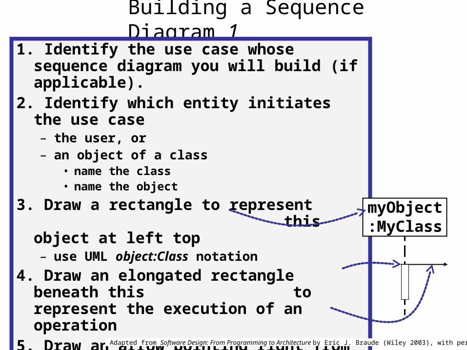
Building a Sequence Diagram 11. Identify the use case whose sequence
diagram you will build (if applicable). 2. Identify which entity initiates the use case
– the user, or– an object of a class
• name the class• name the object
3. Draw a rectangle to represent this object at left top– use UML object:Class notation
4. Draw an elongated rectangle beneath this to represent the execution of an operation
5. Draw an arrow pointing right from its top
myObject:MyClass
Adapted from Software Design: From Programming to Architecture by Eric J. Braude (Wiley 2003), with permission.

Building a Sequence Diagram 2
6. Identify which entity handles the operation initiated – an object of a class
• name the class• name the object
7. Label the arrow with the name of the operation
8. Show a process beginning, using an elongated rectangle
9…… Continue with each new statement of the use case.
myObject:MyClass
myObject1:MyClass1
operation()
Adapted from Software Design: From Programming to Architecture by Eric J. Braude (Wiley 2003), with permission.
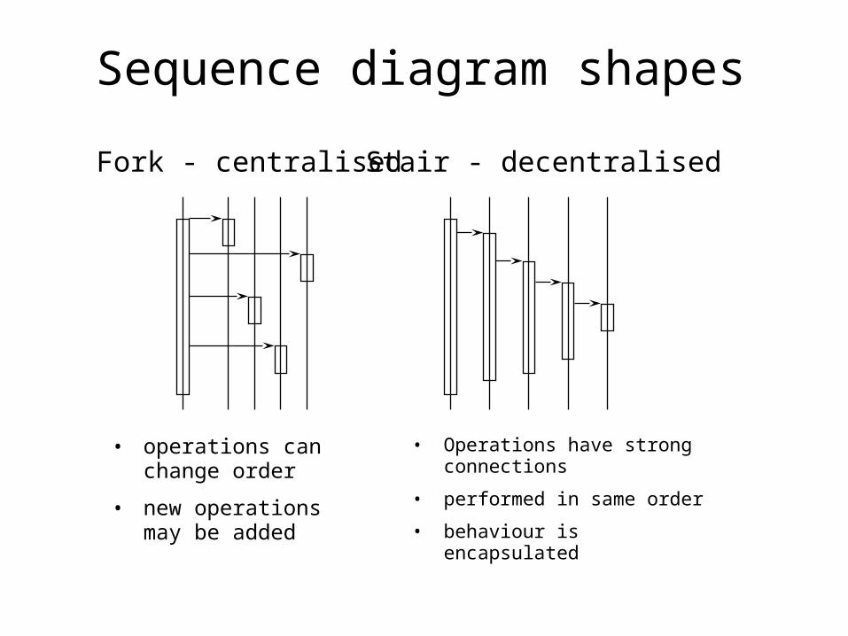
Sequence diagram shapes
Fork - centralised Stair - decentralised
• operations can change order
• new operations may be added
• Operations have strong connections
• performed in same order
• behaviour is encapsulated

Activity Diagrams
• Activity diagrams show the flow among activities associated with a given object using:– activity and action states– transitions– branches– merges– forks– joins
Authorize Payment
Cancel OrderDispatch Order
[succeeded]
[failed]
branch
guardexpressions
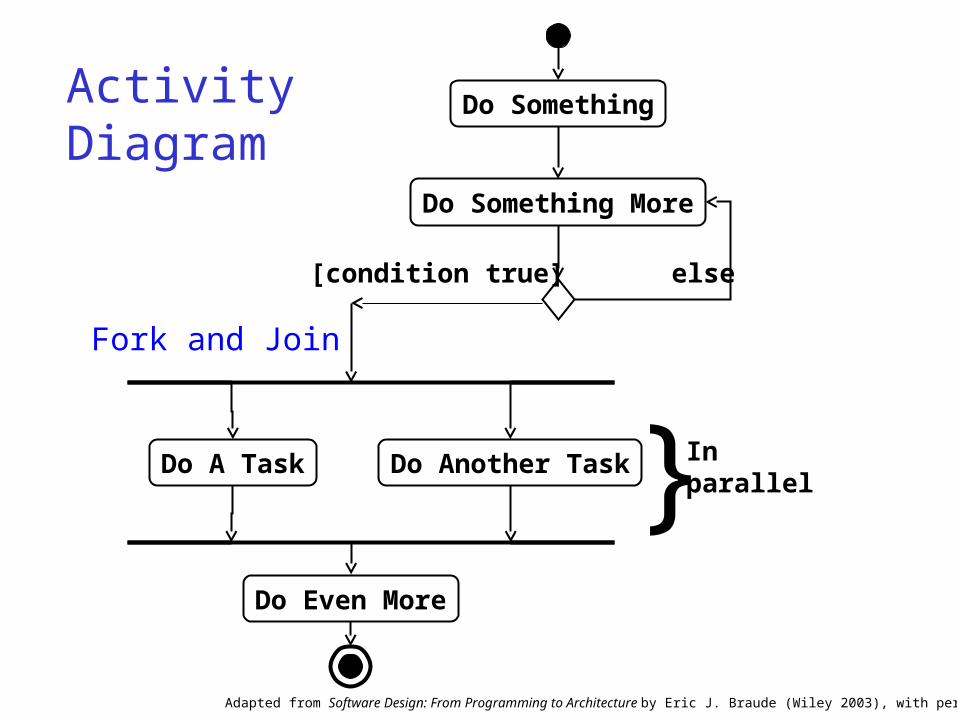
Activity Diagram
Do Something
Do Something More
Do A Task Do Another Task
Do Even More
else[condition true]
} Inparallel
Adapted from Software Design: From Programming to Architecture by Eric J. Braude (Wiley 2003), with permission.
Fork and Join

Receive Order
Check OrderItem
DispatchOrder
Authorize Payment
Cancel Order
Add Remainderto Stock
[succeeded]
[failed]Assign to Order
ReceiveSupply
Choose Outstanding Order Items
Assign to Order
* for each chosenorder item
[in stock]
*for each order item
[need to reorder]
Reorderitem [all outstanding order
items filled]
[stock assigned to all order itemsand payment authorized]
OrderProcessing
Finance StockManager
vertical linesare used to separate“swimlanes”to show which activities are handledby which part of thesystem
Class Diagrams
Structures and Relationships
UML Class Diagrams
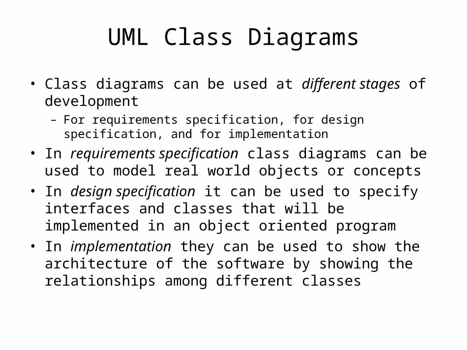
• Class diagrams can be used at different stages of development– For requirements specification, for design specification, and for
implementation
• In requirements specification class diagrams can be used to model real world objects or concepts
• In design specification it can be used to specify interfaces and classes that will be implemented in an object oriented program
• In implementation they can be used to show the architecture of the software by showing the relationships among different classes

Object-Oriented Class Analysis
Object/concept representations
• Domain concept
• Visualization of concept
• Programming language
representation
Book
title
public class book { private String title; public Chapter getChapter();}
UML Classes
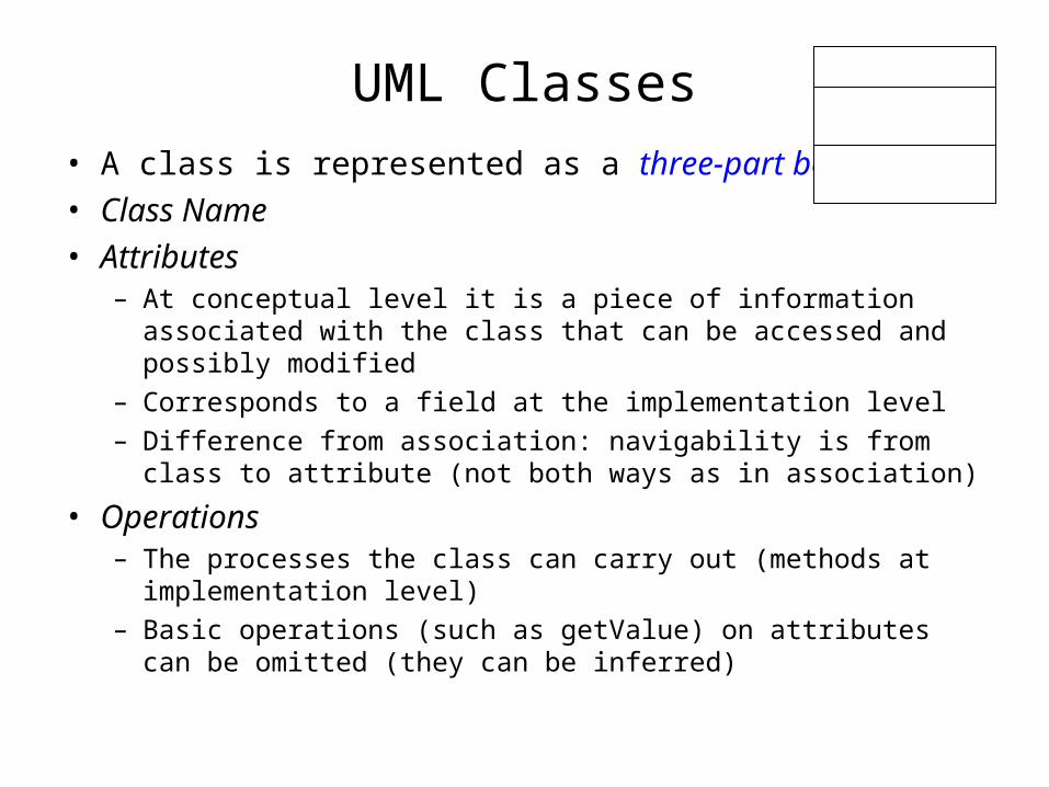
• A class is represented as a three-part box• Class Name• Attributes
– At conceptual level it is a piece of information associated with the class that can be accessed and possibly modified
– Corresponds to a field at the implementation level– Difference from association: navigability is from class to attribute
(not both ways as in association)
• Operations– The processes the class can carry out (methods at
implementation level)– Basic operations (such as getValue) on attributes can be omitted
(they can be inferred)

Class Diagrams
Responsibilities:-- describes each canister undergoing fabrication
+ display()- getNumOpenSlots()+ setStatus()
+ numCanisters: int - numWafers: int- size: float
Canister Class name
Attribute: type
Operations
Place for comments
+:Visiblefrom without
wafer
canister
Adapted from Software Design: From Programming to Architecture by Eric J. Braude (Wiley 2003), with permission.

Class Relationships: 3 Kinds
Window
open()close()
ConsoleWindow DialogBox Control
Event
association
dependencygeneralization

AudioClip
Dependency
• A change in one thing may affect another.• “Uses” relationship.• May have a name, but not common.• Use Dependency to show one thing uses another.
record(m:Microphone)start()stop()
Microphonename
dependency
•Operations of the client class create objects of the supplier class •Operations of the client class have signatures whose return class or arguments or local vars are instances of (or references to) the supplier class
When

class MyDependentClass{ . . . . . void myFunction1( MyReferencedClass r ) { . .. }
MyReferencedClass myFunction2( … ) { . .. }
void myFunction3( … ) { MyReferencedClass m … }}
MyDependentClassatt: intmyFunction()
MyReferencedClass
Dependence : UML Notation … and …Typical Implementation
dependence(reference to a class)
parameter
or return type
or local variable type
Adapted from Software Design: From Programming to Architecture by Eric J. Braude (Wiley 2003), with permission.

Generalization
• Relationship between general thing (parent) and more specific thing (child)
• Child “is-a-kind-of” parent.• Child inherits attributes and operations of parent.• Use when you want to show parent child relationship
Rectangle
Square
PolygonCircle
Shape base class
leaf class
generalization

Associations
• Relations between classes• Roles
– analogous to names of instance variables
• Navigation– bidirectional: each class references the other– unidirectional: A knows B, but B doesn’t know A– no arrow heads: means either “bidirectional” or “not
specified”
• Multiplicities– 0, 1, *, 0..1, 1..*, 5..6, and so on– says how many objects each object knows– would be realized through arrays, sets, lists, and so on
1 *
leftRole rightRole
Associations: Conceptually
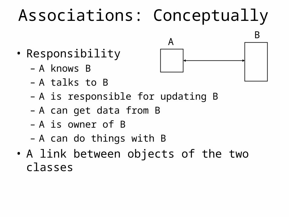
• Responsibility– A knows B– A talks to B– A is responsible for updating B– A can get data from B– A is owner of B– A can do things with B
• A link between objects of the two classes
AB

Associations (UML)
Professor Courseteaches
relationship name
direction indicator:how to read relation name
teacher class
role names Multiplicitydefines the number of objects associated with an instance of the association.
Default of 1; Zero or more (*); n..m; range from n to m inclusiv
e
1..**
• Represent conceptual relationships between classes (structural)

class Employer{ Employee[ ] employees; . . . . .}
class Employee{ Employer[ ] employers; . . . . .}
Employer Employee
Association : UML Notation and Typical Implementation
1..n1..3 employs
is employed by
Adapted from Software Design: From Programming to Architecture by Eric J. Braude (Wiley 2003), with permission.
反應在Attribute 上
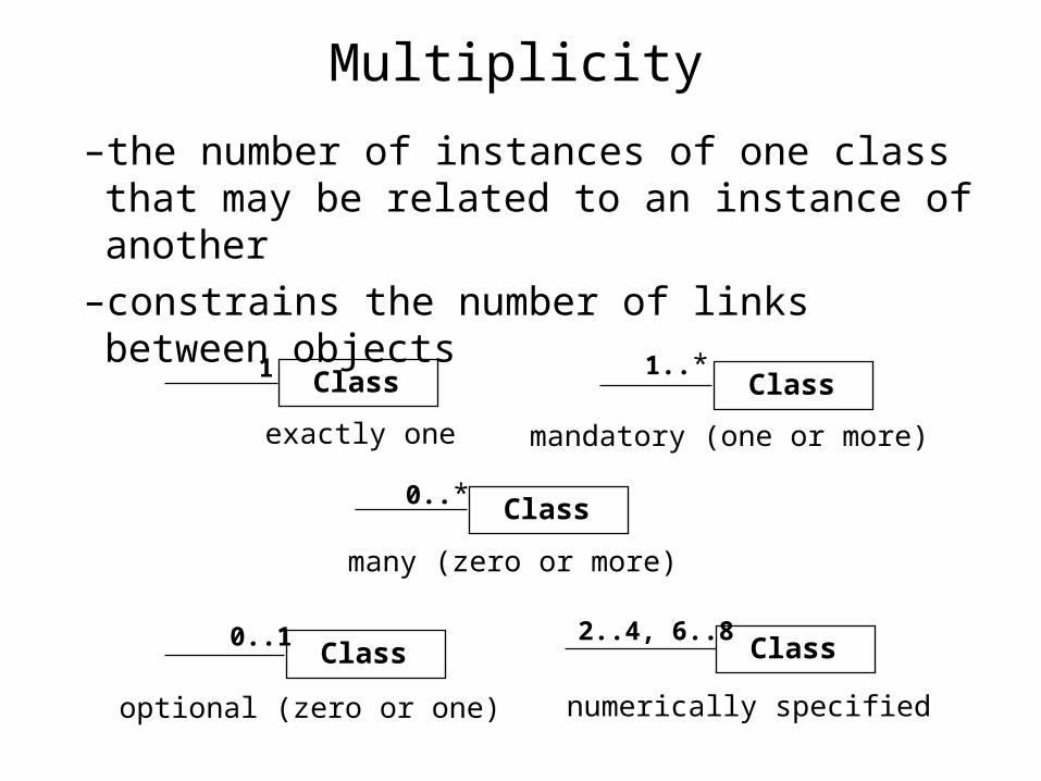
Multiplicity
–the number of instances of one class that may be related to an instance of another
–constrains the number of links between objects
Class
Class
Class
Class
Class
many (zero or more)
optional (zero or one)
mandatory (one or more)
numerically specified
1..*
2..4, 6..8
exactly one
0..*
0..1
1

An Example of Association Modeling from
HL7 Version 3 Tutorial - Reference Information
ModelBy George W. Beeler, Jr., Ph.DBy George W. Beeler, Jr., Ph.D
Patient
name : PNDOB : TSaddress : AD
Doctor
name : PNspecialty : CDphone : TEL
seeks care at
provides care for0..*
1..*
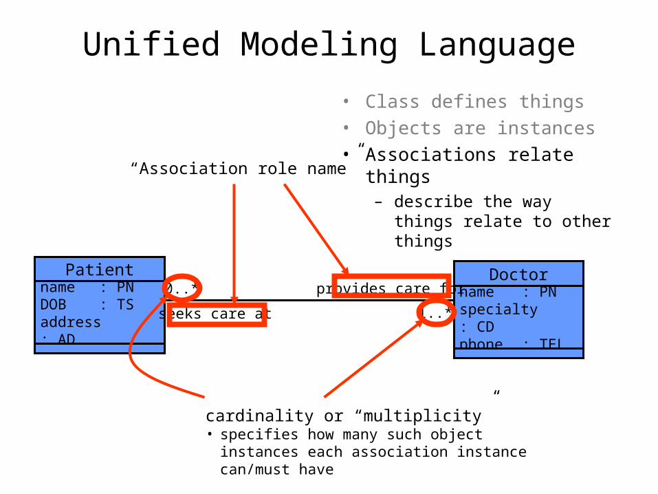
Unified Modeling Language
• Class defines things• Objects are instances• Associations relate things
– describe the way things relate to other things
“Association role name”
cardinality or “multiplicity”• specifies how many such object instances each
association instance can/must have
Patient
name : PNDOB : TSaddress : AD
Doctor
name : PNspecialty : CDphone : TEL
seeks care at
provides care for0..*
1..*
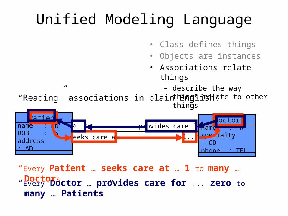
Unified Modeling Language
• Class defines things• Objects are instances• Associations relate things
– describe the way things relate to other things
“Every Patient … seeks care at … 1 to many … Doctors”
“Reading” associations in plain English:
“Every Doctor … provides care for ... zero to many … Patients”

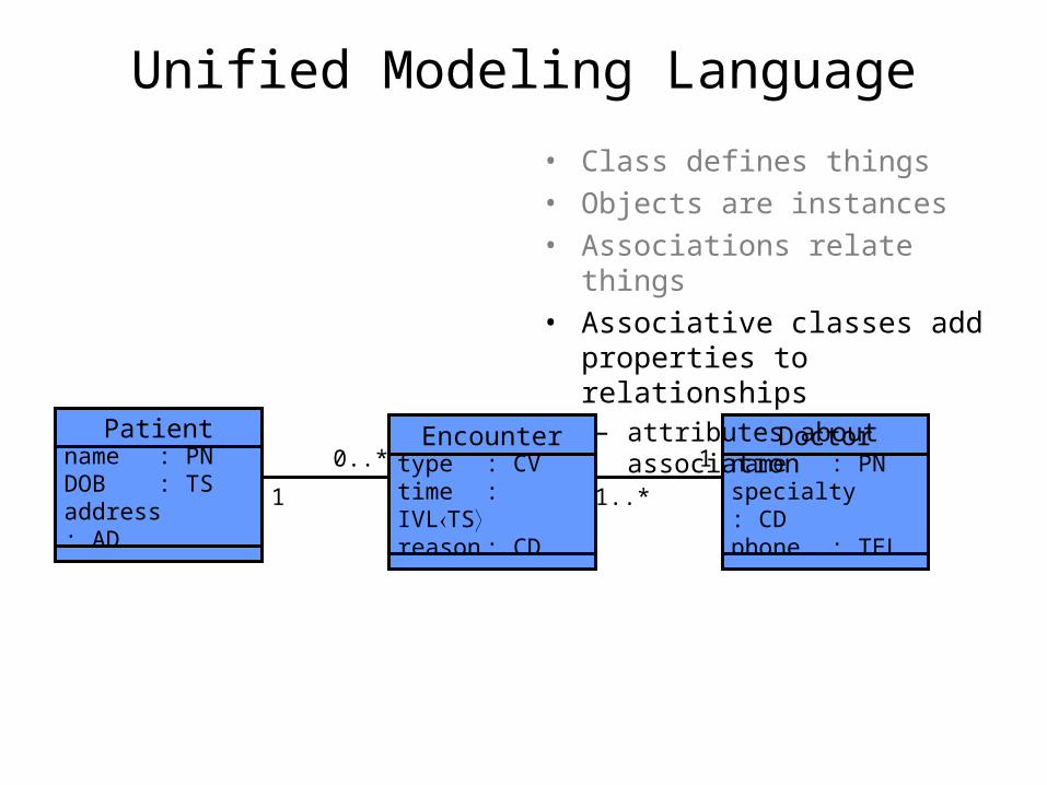
• Class defines things• Objects are instances• Associations relate things• Associative classes add
properties to relationships– attributes about association
Unified Modeling Language
Patient
name : PNDOB : TSaddress : AD
Doctor
name : PNspecialty : CDphone : TEL
seeks care at
provides care for0..*
1..*
Encounter
type : CVtime : IVLTSreason : CD
The most compelling reason for having links and attributes is for many-to-many relationships
Unified Modeling Language
Patient
name : PNDOB : TSaddress : AD
Doctor
name : PNspecialty : CDphone : TEL
1
1..*
Encounter
type : CVtime : IVLTSreason : CD
• Class defines things• Objects are instances• Associations relate things• Associative classes add
properties to relationships– attributes about association
1
0..*
Unified Modeling Language
Patient
gender : CDdonor : BLV.I.P. : BL
Doctor
specialty : CDphone : TELprivileges : CV
Person
name : PNDOB : TSaddress : AD
1
1..*
Encounter
type : CVtime : IVLTSreason : CD
1
0..*
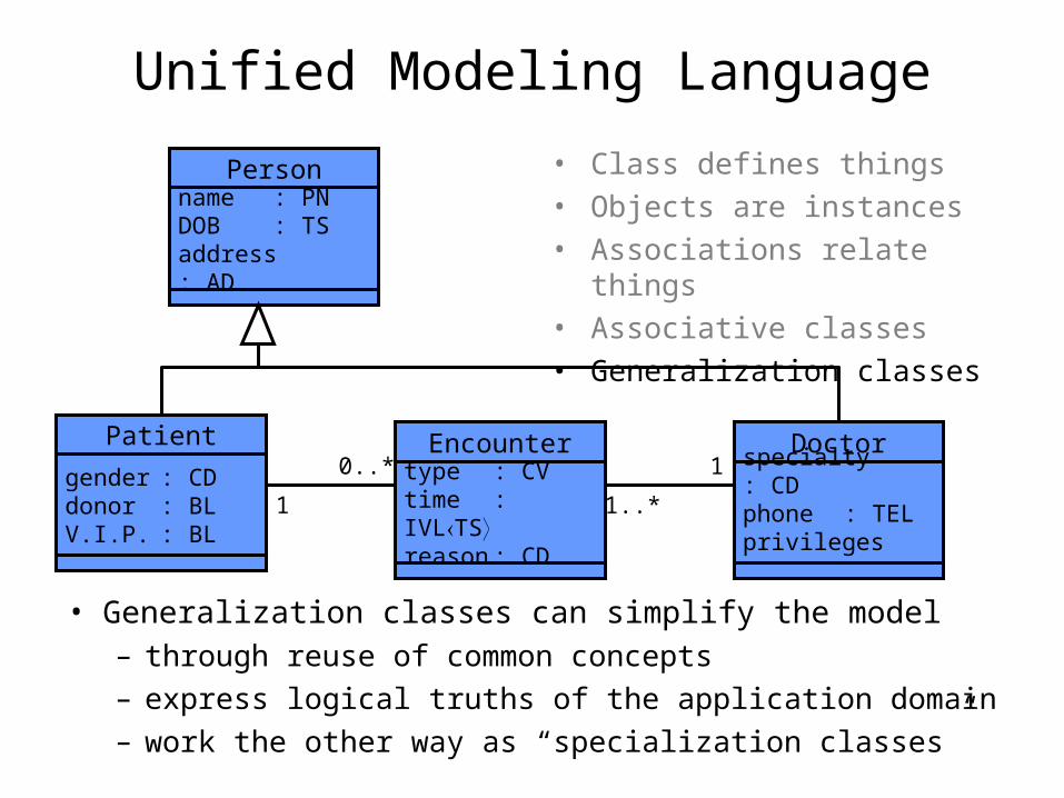
• Class defines things• Objects are instances• Associations relate things• Associative classes• Generalization classes
• Generalization classes can simplify the model– through reuse of common concepts– express logical truths of the application domain– work the other way as “specialization classes”
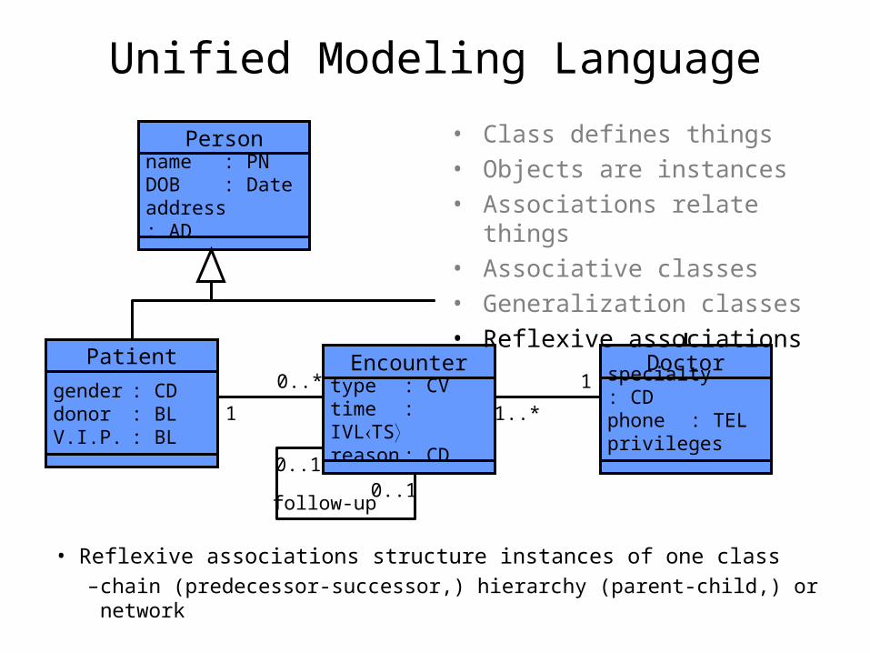
Unified Modeling Language
Patient
gender : CDdonor : BLV.I.P. : BL
Doctor
specialty : CDphone : TELprivileges : CV
Person
name : PNDOB : Dateaddress : AD
1
1..*
Encounter
type : CVtime : IVLTSreason : CD
1
0..*
0..10..1
follow-up
• Class defines things• Objects are instances• Associations relate things• Associative classes• Generalization classes• Reflexive associations
• Reflexive associations structure instances of one class–chain (predecessor-successor,) hierarchy (parent-child,) or network
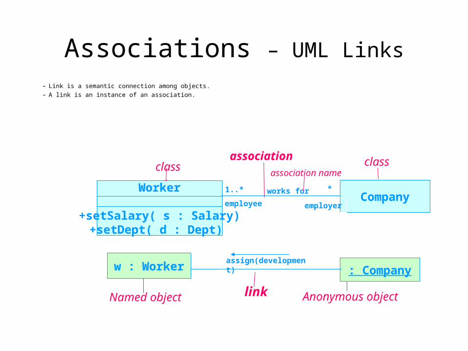
Associations – UML Links
– Link is a semantic connection among objects.
– A link is an instance of an association.
Company1..* *
employee employer
: Companyassign(development)
w : Worker
linkNamed object Anonymous object
classassociation class
Worker
+setSalary( s : Salary)+setDept( d : Dept)
works for
association name

Associations – Link Attributes• Link Attributes
The most compelling reason for having links and attributes is for many-to-many relationships
File User
access permission
File User
access permission
• UML Association Class
AccessRight
* 1..*
link attribute
association class
class class
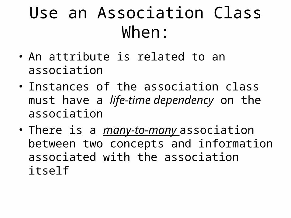
Use an Association Class When:
• An attribute is related to an association• Instances of the association class must have a
life-time dependency on the association• There is a many-to-many association between
two concepts and information associated with the association itself
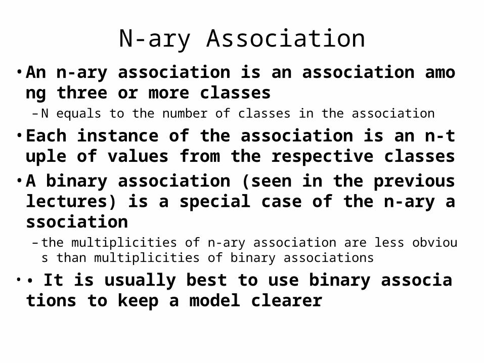
N-ary Association• An n-ary association is an association among thr
ee or more classes – N equals to the number of classes in the association
• Each instance of the association is an n-tuple of values from the respective classes
• A binary association (seen in the previous lectures) is a special case of the n-ary association– the multiplicities of n-ary association are less obvious than multipliciti
es of binary associations
• • It is usually best to use binary associations to keep a model clearer

Example
Association class
Indicates n-ary association
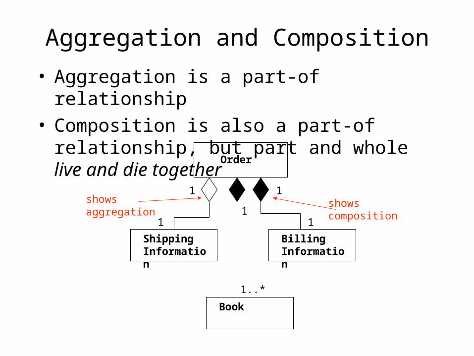
Aggregation and Composition
• Aggregation is a part-of relationship• Composition is also a part-of relationship, but
part and whole live and die together
Order
BillingInformation
ShippingInformation
1
1
1
1
Book
1
1..*
showsaggregation
showscomposition
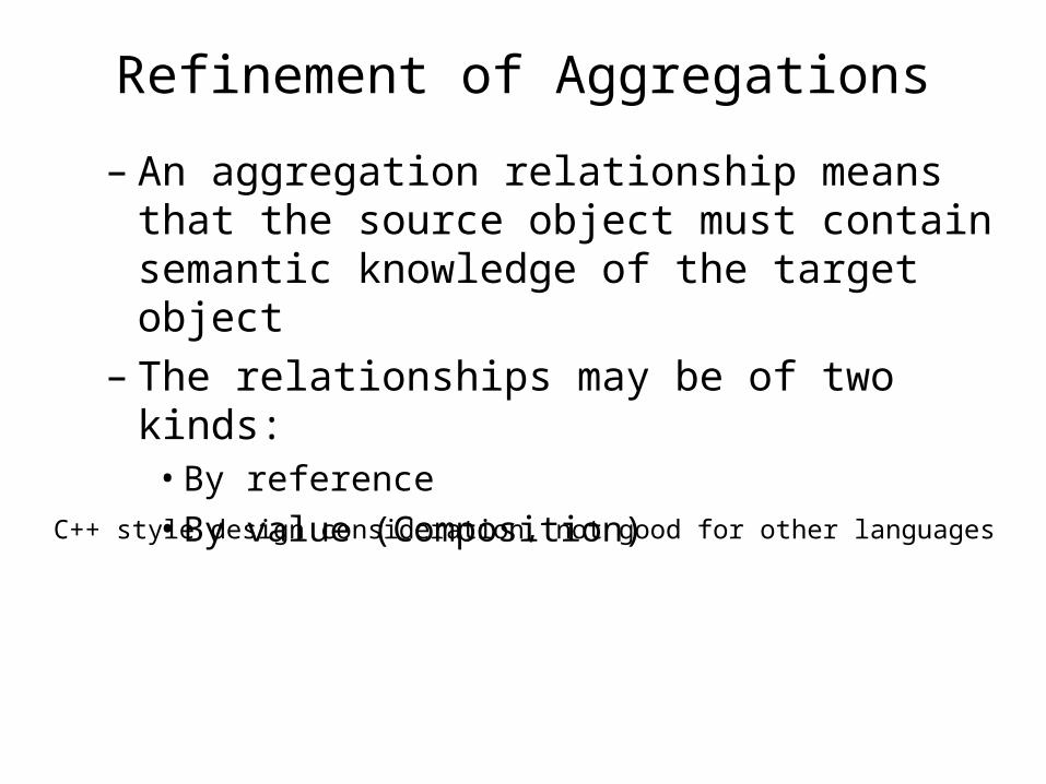
Refinement of Aggregations
– An aggregation relationship means that the source object must contain semantic knowledge of the target object
– The relationships may be of two kinds:• By reference• By value (Composition)
C++ style design consideration, not good for other languages
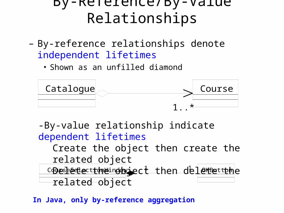
By-Reference/By-Value Relationships
– By-reference relationships denote independent lifetimes
• Shown as an unfilled diamond
CourseCatalogue
1..*1..*
OKButtonCourseSelectionWindow 1 111
-By-value relationship indicate dependent lifetimesCreate the object then create the related objectDelete the object then delete the related object
In Java, only by-reference aggregation

Recursive Aggregation
–aggregation can be -
FIXED - the number and type of the parts is fixed
VARIABLE - the number of parts may vary, but the number of levels is fixed
RECURSIVE - the number of levels, and hence parts, is unlimited
Block
Compoundstatement
Simplestatement
Program* *
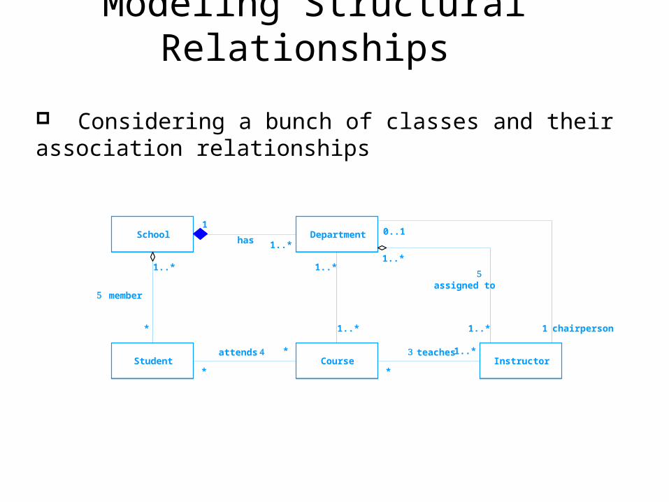
Modeling Structural Relationships
School
InstructorCourse
Department
Student
*
1..*
1..*
1
has
member
*
*attends
*
1..* teaches
1..*
1..* 1..*
1..*
0..1
1 chairperson
assigned to
Considering a bunch of classes and their association relationships

Parameterized Classes (Template)
• Class List represents a collection of objects of a class• That class becomes a parameter to the parameterized
class - e.g. list of accounts
List
Insert(T)Remove(T)
T
AccountList<<bind>>
T to Account
Parameterized class
Parameter
T

STATE-1
STATE-3 Event-d
Event-aEvent-c
result
STATE-2Event-b
Event-e
UML State Diagrams• nodes represent states: rounded rectangles with state name
– initial state represented as solid circle
– final state represented as bull’s eye
• edges represent transitions between states and are labeled with an event name (the trigger)

How do they all fit together?
• Functionality– use case diagrams
• Decomposition– class diagrams (class structure)– package diagrams, deployment diagrams (architecture)
• Behavior– state diagrams, activity diagrams
• Communication– sequence diagrams, collaboration diagrams
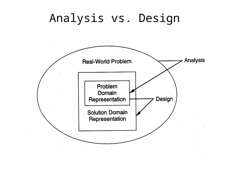
Analysis vs. Design

Analysis and Design
Analysis—“what”
investigation of the problem and requirements
Design—“how”
description of a software solution
Requirements
Use cases
Constraints
Vocabulary
Objects
Architecture
Deployment
UI

OOA and OOD
• OO techniques can be used in analysis (req) as well as design
• The methods and notations are similar• In OOA we model the problem, while in OOD we model t
he solution• Often OOA structures are subsumed in the solution dom
ain structures• The line between OOA and OOD is not fixed
Summary
• Software Development Process• Requirement Analysis and Specification
– Use Case Modeling
• The Unified Modeling Language– Class diagrams
• Association, Dependency, Inheritance, Aggregation
– Sequence diagrams– Activity diagrams– State diagrams
• From OOA to OOD