© lattice semiconductor corporation 2002 1 in-system programmable programmable analog circuits...
TRANSCRIPT

© LATTICE SEMICONDUCTOR CORPORATION 2002 1
In-System Programmable In-System Programmable PROGRAMMABLE ANALOG CIRCUITS PROGRAMMABLE ANALOG CIRCUITS
ispPAC™ispPAC™
PowerPAC1208

© LATTICE SEMICONDUCTOR CORPORATION 2002 2
AgendaAgenda
• What is PowerPAC
• Details of PowerPAC
• Application Example
• PAC-Designer 1.9.1 – Demonstration
• Summary

© LATTICE SEMICONDUCTOR CORPORATION 2002 3
ispPAC-POWR1208-01T44IispPAC-POWR1208-01T44ISingle Chip, In-System Programmable Single Chip, In-System Programmable
Power Sequencing & Monitoring SolutionPower Sequencing & Monitoring Solution
What is PowerPAC?What is PowerPAC?

© LATTICE SEMICONDUCTOR CORPORATION 2002 4
Where Does PowerPAC Fit On a Board?Where Does PowerPAC Fit On a Board?
Multi-SupplyCircuit Board
Board PowerSupplySection
3.3V3.3V
2.5V
Sequenced 3.3 V Bus
3.3 V Input
Supply
Sequenced 2.5 V BusSupplyBrick2.5V
PowerPAC
1.8VLDO/Brick
1.8V Bus
SupervisorySignals
FET/ LDO/BrickEnable
MonitorVoltages

© LATTICE SEMICONDUCTOR CORPORATION 2002 5
PowerPAC1208 Block DiagramPowerPAC1208 Block Diagram
SequenceController
CPLD
32 I/P & 16Macrocell
GLB
ComparatorOutputs
High VoltageOutputs
VMON1VMON2VMON3
VMON4VMON5VMON6VMON7
VMON8VMON9
VMON10VMON11VMON12
AnalogInputs
CLKIO
IN1
IN2IN3IN4
DigitalInputs
250kHzInternal
OSC
4 TimersLogic
Outputs
12
8
4
4
5
COMP1COMP2COMP3
COMP4COMP5COMP6COMP7
COMP8
OUT5OUT6OUT7OUT8
HVOUT1HVOUT2HVOUT3HVOUT4
VDD
PowerPAC
Monitors SupplyVoltages
MonitorsDigitalSignals External Clock for
Longer Time Delay
SupervisorySignals
FET GateDrive /
SupervisorySignal
ComparatorOutputs for
ExternalLogic
Expansion& Control
JTAG
Vdd = 2.25V to 5.5V
44-Pin TQFP
© LATTICE SEMICONDUCTOR CORPORATION 2002 6
PowerPAC’s Ruggedized OperationPowerPAC’s Ruggedized Operation
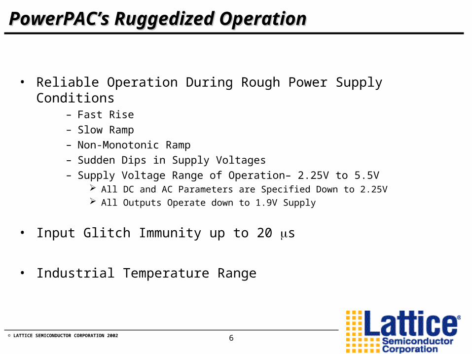
• Reliable Operation During Rough Power Supply Conditions– Fast Rise– Slow Ramp– Non-Monotonic Ramp– Sudden Dips in Supply Voltages– Supply Voltage Range of Operation– 2.25V to 5.5V
All DC and AC Parameters are Specified Down to 2.25V All Outputs Operate down to 1.9V Supply
• Input Glitch Immunity up to 20 s
• Industrial Temperature Range

© LATTICE SEMICONDUCTOR CORPORATION 2002 7
Analog Section:• 12 Comparators – To Monitor Power Supply Voltages
– Individual Programmable Threshold 1% Threshold Resolution around 6 popular Power Supply Voltages 192 Steps
– Input Hysteresis Auto-Scales With Monitor Voltage Maintains Noise Tolerance Across Supply Voltages
– Programmable Input Glitch Filter
• 4 FET Drivers – To Enable/Sequence Power Supply Bus– Power Supply Ramp Rate - Controlled To Meet Device Specifications
Programmable Output Current Feed – 500 nA to 50 uA – 32 steps
– Internally Charge Pumped – To Reduce MOSFET On-Resistance Configurable High Voltage for FET Driver – 8V to 12.5V – 8 Steps
To Meet Gate Voltages for Different Power Supplies
– Configurable as Open Drain Output - For Digital Control
Features of PowerPAC1208Features of PowerPAC1208

© LATTICE SEMICONDUCTOR CORPORATION 2002 8
PowerPAC1208 Programmable DelaysPowerPAC1208 Programmable Delays
3.3V Supply
2.5V Supply
Composite Plot Showing 6 Different Delay Settings for the 2.5V Control Signal.
16ms Delay8ms4ms2ms

© LATTICE SEMICONDUCTOR CORPORATION 2002 9
PowerPAC1208 Slew Rate ControlPowerPAC1208 Slew Rate Control
FET Driver Ramp Currentand Max Voltage
3.3V Supply2.5V Supply
Composite Plot Using Different Ramp Currents for the 2.5V HVOUT Signal.
Select Output Mode

© LATTICE SEMICONDUCTOR CORPORATION 2002 10
Digital Section:• 16 Macrocell CPLD (Similar to ispMACH4000 Macrocell)
– Supports Supply Sequencing & Supervisory Signal Generation
– Ruggedized to Operate Reliably Under Noisy Environments
– 32 Input, 80 Product Term
• 250 kHz Oscillator – Flexible Timing Generation– Pre-scalar for Slower PLD Operation Down to 2 kHz Clock
• 4 Programmable Timers– Programmable Duration –Implements Delays for Power Supply
Stabilization, Watchdog Timers, etc. 32 us to 512 ms with Internal Oscillator – 16 Steps Extend Timer Duration to Any Length Using External Clock
– Controlled by Macrocell Output – Reuse the Same Timer Under Different Logic Conditions
Features of PowerPAC1208 – Cont’dFeatures of PowerPAC1208 – Cont’d

© LATTICE SEMICONDUCTOR CORPORATION 2002 11
Features of PowerPAC1208 – Cont’dFeatures of PowerPAC1208 – Cont’d
• 4 Digital Inputs– Logic Input Standards Compliance Set By VDDINP Pin
CMOS 5.0, LVCMOS 3.3, LVCMOS 2.5
• 4 Open Drain Outputs– Supports Various Interface Standards Through External Pull-Ups
• 8 Comparator Direct Outputs– Logic Expansion
– Drive Voltage Tracking Transistors
– Easy interface to Existing System Level Initialization Logic

© LATTICE SEMICONDUCTOR CORPORATION 2002 12
Complete & Flexible Power Sequencing & Complete & Flexible Power Sequencing & Monitoring SolutionMonitoring Solution
• Integration - Combines Analog & Digital Functionality- Ruggedized Operation Increases Reliability
• Programmability- Threshold Voltages- CPLD for Sequencing, Monitoring Logic Implementation- FET Driver for Controlling Power Supply Ramp Rate- Programmable Long-Duration Timers
SummarySummary

© LATTICE SEMICONDUCTOR CORPORATION 2002 13
Application ExampleApplication Example

© LATTICE SEMICONDUCTOR CORPORATION 2002 14
Example Power Supply Problem StatementExample Power Supply Problem Statement
• Supervisory Signal Generation1. Activate Power_OK signal
and Deactivate CPU-Reset Signal After all Supplies are Turned On
• Monitoring Power Supply Voltages1. If Any Voltage Drops
Below Threshold, Reset Processor & Remove All Power
Card PowerTurned On
Turn-on 1.8VSupply for CPU
Turn-on 2.5VSupply for ASIC
& CPU I/O
Turn-on 3.3VSupply for ASIC
I/O & OtherDevices
Card Power-upComplete
Step - 2
Step - 3
Step - 4
Step - 1
Step - 5
Step-by-StepPowering Up aMulti-VoltageCircuit Board
Power Sequencing Application

© LATTICE SEMICONDUCTOR CORPORATION 2002 15
Example ApplicationExample Application
Other BoardCircuitry
PowerPAC1208
Device 3.3V Power Bus
CPU Core Voltage
ASIC & I/O Voltage Bus2.5VBrick
1.8VLDO
3.3VInput
Supply
Vin
_3
V3
_O
ve
r3V
2
FE
T_
Dri
ve
r_3
V3
LD
O1
V8
_E
n
Bri
ck
2V
5_
En
De
v_
1V
8_
Ov
er1
V7
De
v_
2V
5_
Ov
er2
V4
CPU_Reset
Power_Good
Power Supply Monitoring, Sequencing, &Supervisory Signal Generation

© LATTICE SEMICONDUCTOR CORPORATION 2002 16
Power Supply Sequence StepsPower Supply Sequence StepsSTEP CONDITION/ACTION COMMENTS
1 Wait for 3.3 V supply > 3V Wait for 3.3V to stabilize within 10% margin
2Enable 1.8 LDO = 1, CPU-Reset = 0 Hold the reset active when the CPU is powered
on
3 Wait for 1.8V > 1.7V Wait for LDO voltage to stabilize
4 Enable 2.5V Power Supply Brick = 1
5 Wait for 2.5V supply > 2.375V Wait for the 2.5V to stabilize within the 5% margin
6 Power-Good signal = 1 Signal to FPGA to Load
7 Wait for 50 ms Wait for FPGA to load, and the ASIC to initialize
8 CPU-Reset = 1 CPU is now ready to execute
9 <Board Power up complete>
10 POWER-DOWN SEQUENCE Enter here under fault condition
11 CPU-Reset = 0 Prevent CPU from corrupting memory
12Enable 2.5V Power Supply Brick = 0; Enable 1.8 LDO = 0
Remove the 2.5V power supply and remove the 1.8V supply to CPU
13 Jump to step 13 Stop

© LATTICE SEMICONDUCTOR CORPORATION 2002 17
Handling Power Supply Fault ConditionHandling Power Supply Fault Condition
Monitor Condition Outputs Go to Sequence Step
Comments
IF (Power_good = 1) AND
(( 3.3V is < 3V) OR (2.5V < 2.375)
OR (1.8V < 1.71))
Power_good signal = 0
Step 10 If one of the power supply voltages drops below lower limit, initiate shut down

© LATTICE SEMICONDUCTOR CORPORATION 2002 18
PAC-Designer 1.9.1PAC-Designer 1.9.1DemonstrationDemonstration

© LATTICE SEMICONDUCTOR CORPORATION 2002 19
What’s New in PAC-Designer 1.9.1 - For PowerPACWhat’s New in PAC-Designer 1.9.1 - For PowerPAC
• Hierarchical Design Entry– Easy System Interface Parametric Specification
• PAC LogiBuilder - The Logic Wizard– Map Power Supply Sequencing & Monitoring Steps Directly into Design
Advanced Features: Supply Glitch Monitor, Watchdog Timer, etc.
– Fits Code Into PLD Automatically
• Lattice Simulator– Waveform Viewer
– Waveform Stimulus Editor

© LATTICE SEMICONDUCTOR CORPORATION 2002 20
First .. High Level Design EntryFirst .. High Level Design Entry
© LATTICE SEMICONDUCTOR CORPORATION 2002 21
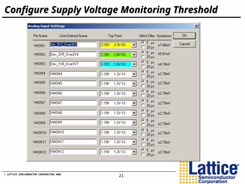
Configure Supply Voltage Monitoring ThresholdConfigure Supply Voltage Monitoring Threshold

© LATTICE SEMICONDUCTOR CORPORATION 2002 22
Summary – Hierarchical Design EntrySummary – Hierarchical Design Entry
• Easy System Interface Parametric Specification
– Setting Monitor Threshold Voltage, Signal Names
– FET Gate Drive Voltage & Current
– Selecting Internal/External Clock & Timer Values

© LATTICE SEMICONDUCTOR CORPORATION 2002 23
Second: Build Sequence Control ProgramSecond: Build Sequence Control ProgramNo New Language to Learn!
Double-Click On the Line &
Pick Instructions From Menu

© LATTICE SEMICONDUCTOR CORPORATION 2002 24
And .. Build Expressions InteractivelyAnd .. Build Expressions Interactively

© LATTICE SEMICONDUCTOR CORPORATION 2002 25
Easily Translates Into PAC LogiBuilder Program
Detailed Application Requirement Detailed Application Requirement
© LATTICE SEMICONDUCTOR CORPORATION 2002 26
And.. Fits into a PowerPAC1208!And.. Fits into a PowerPAC1208!

© LATTICE SEMICONDUCTOR CORPORATION 2002 27
PAC LogiBuilder - SummaryPAC LogiBuilder - Summary
• Intuitive Translation of Power Sequencing & Monitoring Requirement
– No New Language to Learn
– Simple Point & Click Instructions Power Supply Sequence Design Power Supply Monitor Design Supervisory Signal Specification 5 Basic Instructions & 3 Advanced Instructions
– Fitting the Design into On-board CPLD of PowerPAC

© LATTICE SEMICONDUCTOR CORPORATION 2002 28
Third: Create Stimulus Using Waveform EditorThird: Create Stimulus Using Waveform Editor

© LATTICE SEMICONDUCTOR CORPORATION 2002 29
Verify the Design Using The Lattice SimulatorVerify the Design Using The Lattice Simulator

© LATTICE SEMICONDUCTOR CORPORATION 2002 30
Finally: “ispProgram” the DeviceFinally: “ispProgram” the Device
ispDOWNLOAD Cable• Same Cable Used For Programming Lattice CPLD
PowerPAC Evaluation Board
JTAG

© LATTICE SEMICONDUCTOR CORPORATION 2002 31
PAC-Designer 1.9.1 - SummaryPAC-Designer 1.9.1 - Summary
• Hierarchical System Interface Definition– Easy System Interface Parametric Specification
• PAC LogiBuilder– Easy Design of Sequencing & Monitoring
– Intuitive Point & Click Instructions
• Lattice Waveform Editing & Simulation– Verify Design Before Wiring up Prototype

© LATTICE SEMICONDUCTOR CORPORATION 2002 32
Additional Documentation…..Additional Documentation…..
• Application Notes
• Sparkle Sheet
• DataSheet
• PAC-Designer 1.9.1

© LATTICE SEMICONDUCTOR CORPORATION 2002 33
PowerPAC1208 & PACsystemPowerPAC1208 & PACsystem
• ispPAC-POWR1208-01T44I– Available in 44-Pin TQFP Package Only– Temperature Range - -40C to +85C
• Evaluation – PAC-SystemPOWR1208– Evaluation Board – PAC-POWR1208-EV– PAC-Designer 1.9.1 Software CD
• Includes Latest Datasheets & Applications Notes
– Price: $149

© LATTICE SEMICONDUCTOR CORPORATION 2002 34
SummarySummary
• Integration– PowerPAC Offers Single-Chip Solution For Sequencing & Monitoring– Board Space Savings– Increased Reliability
• Software– Simplifies Interfacing PowerPAC to Various Power Supplies & FETs– PAC LogiBuilder – Easy Implementation of Sequencing and Monitoring
Algorithms– Wave Stimulus and Waveform View Ease Verification
• Programmability– Flexibility in Sequencing, Threshold Voltage, Delays, FET Gate Driver– Inventory Reduction – PowerPAC can be Tailored to Control Many
Types of Power Supply Arrangements– EECMOS Technology + ISP Allows Easy Tuning of Design