oscillographs - irwin - 1925/oscillographscrt004063mbp.pdfoscillographs aconcise treatise...
TRANSCRIPT


OSCILLOGRAPHSA CONCISE TREATISE ON THE THEORYCONSTRUCTION, AND USE OF ELECTRO-MAGNETIC, HOT-WIRE, ELEOTROSTAND CATHODE RAT OSCILLOGR
BY
J. T. IRWINAflBtHHAJB K3HBHB OJ THB .pjtfJll'U'IIUH" OF i
mronraaEa ; BOMBTIJCH LHOTUMB nr maraioAi DBSKHTAJTD KHAfltJSaiCBHTe AT TEH JKP1EIAI, OOLUJQ1
AflT) THOHNOLOQT, LOHD01T
LONDONSIR ISAAC PITMAN & SONS, LTD.PARKER STREET, KTNGSWAY, W.C.2BATH, MELBOURNE, TOBONTO, NBW YOBK
1925
PKIKIXD Df CHEAT BRITAINAT TIIX nTKAM FKXW, BATH
^

THIS book is dedicated to my friend Mr.
S. . S. A. WatkLnfl, my colleague for many
years at the City and Guilds Engineering
College, London. He gave me much valu-
able help on oscillographs, and rediscovered
the method of damping oscillographs bymeans of a resonant shunt when working
independently of me in America.
mJ. T. LRWIN.
BOVAILY,
IRELAND.


PREFACEwho worked at the Central Technical College,
Condon (now the City and Guilds (Eng.) College, underProfessor Ayrton, or later under Professor Mather, will
understand the happy conditions which made possiblethe greater portion of the work represented by this
book. While routine work had to be carried out with
great care, every encouragement was given to work ofan original character, and difficult problems were
subjected to constructive and friendly criticism.
Equally happy were the relations between the juniormembers of the staff, and the author has to acknowledgethe help received from his former colleagues and also
from a long line of able students who assisted him with
experiments. It would be almost impossible to makea complete list of these, and it would be imfa-ir to those
l|ft out if an incomplete list were published. Specialmention must, however, be made of the valuable helpreceived from Mr. F. W. Andrews, the instrument makerat the College, and from Mr. J. King the laboratoryattendant.
With regard to the book itself the a-im has been tomake it suitable for any technical student of ordinary
'ability, as the mathematics do not go beyond the
simplest integral and differential calculus, and the
apparent complexity of some of the proofs is due onlyto a desire to put in all the steps necessary to the
solution of the problem., The only exception to this is the portion due to
Mr. Hodgson and specially indicated in the text. This
/
vi Preface
pprtion, which, involves higher mathematics, can be
skipped by those unable to follow the proof, and theresults accepted so that there may be no break in the
sequence.The Cambridge Instrument Co. and Mr. R. W. Paul
have been closely identified with oscillograph develop-ment in England, and the author has to acknowledgehis indebtedness to these firms (now amalgamated as
the Cambridge Instrument Co), for the loan of blocks
referring to their products. Permission has also been
kindly given to use Figs. 73-76, taken from Dufour'sbook on the cathode ray oscillograph.The reading of the proofs was carried out by my
friend and former student, Mr. R. E. Neale, in a verythorough manner, and many; additions and explanationsare due to him.
As the work is to a great extent original, and as theauthor has had no facilities for confirming some of thelater theoretical results, he would be glad if anyonecarrying out investigations along the lines mentionedwould communicate the results to the editor or theauthor. He would also like to have any inaccuracies
pointed out.
J. T. IRWTN.
PREFACE
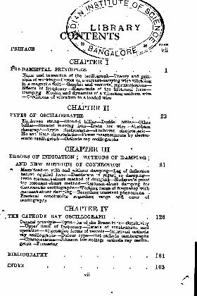
CHAPTER*!PRINCIPLES 1
Name and invention of the oscillograph Theory and prin-ciple of working Forces on a current-carrying wire vibratingin a magnetic field Graphic and vectorial representationsEffects of frequency Magnitude of the frfctional forceDamping Motion and dynamics of a vibrating uniform wire
Conditions of vibration in a loaded wire
CHAPTER IITYPES OF OSOTLLOGBAPH8 . . . .23
Einthoven string Blondel bifllar Duddell bifllar Otherbifllar Blondel moving iron trwin hot wire Abrahamrheograph Irwin electrostatic Einthoven electrostaticHo and Kato electrostatic Power measurements by electro-static oscillograph Cathode ray oscillographs
CHAPTERERRORS OB1 INDICATION
; METHODS OF DAMPINGJ
AND NEW METHODS OF CONNECTION . .81m Magnification with and without damping Lag of deflection
behind applied force Desiderata in regard to dampingIrwin resonant-shunt method of damping Hodgson's prooffor resonant-shunt method Resonant-shunt damping forelectrostatic oscillographs Working range of frequency withresonant -shunt damping Recording transient phenomenaPractical conclusions regarding range and error ofoscillographs
CHAPTER IV.THE CATHODE BAT OSOILLOGBAPH . . . 126
General principle Dynamics of the Brann tube SensitivityUpper limit of frequency Details of construction and
operation Alternative forms of records Improved cathoderay oscillographs Dufour type Hot cathode oscillographs
Characteristics Johnson low-voltage cathode ray oscillo-
graph Focussing
BIBLIOGRAPHY ...... 161
163
SYMBOLS AND ABBREVIATIONSTKB following symbols and abbreviations adopted bythe International Eleotrotecnnical Commission are usedin this volume
A = amperemA = milliampere
/*A = microampereV = volt
/jl?= microfarad
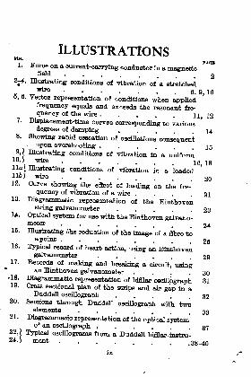
ILLUSTRATIONSKG.
1. Force on a current-carrying conductor in a magneticfield . 2
2j4. Illustrating conditions of vibration of a stretchedwire '
. . 6, 9, 106, 6. Vector representation of conditions when applied
frequency equals and exceeds the resonant fre-
quency of the wire..... 11 127. Displacement-time curves corresponding to various
degrees of damping .... 148. Showing rapid cessation of oscillations consequent
upon overshooting...... 159J Illustrating conditions of vibration in a uniform
10.) wire ...... 16 18lla) Illustrating conditions of vibration in a loaded116) wire . 2012. Curve showing the effect of loading on the fre-'
quenoy of vibration of a wire . . . .2113. Diagrammatic representation of the Einthoven
string galvanometer ..... 28I/. Optical system for use with the Einthoven galvano-
meter ...... 2416. Illustrating the reduction of the image of a fibre to
a point 2616. Typical record of heart action, nging on Einthoven
galvanometer ...... 2917. Becords of Trmlring and breaking a circuit, using
an Einthoven galvanometer . . . . 30-18. Diagrammatic representation of bifllar oscillograph 8119. Gross sectional plan of the strips and air gap in a
Duddell oscillograph . . . 3220. Sections through Duddell oscillograph with two
elements .... 332 1 . Diagrammatic representation of the optical system
of an oscillograph ^ ..... 3722>i Typical osdllograms from a Duddell bifllar instru-24. \ ment g8_4

Illustrations
PAQH.
25. Diagrammatic representation of the Blondel movingiron oscillograph ...... 40
26. Illustrating method of polarizing in the Irwinhot-wire oscillograph ..... 43
27J Illustrating method of compensating for thermal28.) lag in the Irwin hot-wire oscillograph . 44, 4829. Illustrating method of tying together the wires of an *
Irwin hot-wire oscillograph ... 4930 /
3 1 ! J
Hot~wlre oscillograph with movement not in oil . 50
32. Illustrating one method of compensating for inertiaand damping in the Abraham rheograph . . 58
33. Illustrating the use of a rheograph to record instan-taneous pressure ...... 68
34. Sectional plan of the Irwin electrostatic oscillograph 6036. Connection diagram for an electrostatic oscillograph
used to indicate pressure .... 6236. Illustrating the calculation of the capacity of a
wire with regard to a plate .... 6587. Diagrammatic representation of the Ho and Kato
electrostatic oscillograph .... 7038. Connections for the Ho and Kato electrostatic
oscillograph . . . . . .
. -7039. Illustrating the principle of the electrostatic
wattmeter ....... 7240. Illustratingthemeasurement of highfrequencypower 7341. Connections for an electrostatic oscillograph work-
ing on 40,000 volts ..... 7542. [ Records obtained with an electrostatic oscillograph43. J on 40,000 volts ...... 7644. / Records illustrating the use of an electrostatic46. ) oscillograph as a wattmeter . . . . 7847. Vector diagram of the forces in an oscillograph
with very little damping . . . .8248 C
Uurvea showing magnification and lag of oscillo-
4.9 'jgraph deflection at various frequencies and with
A different values of damping . . . 83 8550. Vector diagram showing combination of forces to
determine angle of lag of deflection ... 86

Illustrations si
_ t51. Ourvee showing magnification and lag of oscillo-
graph deflection at various frequencies, withcritical and twice critical damping . . .87
62, ) Connections and vector diagram for the Irwin68. ) resonant-shunt for electromagnetic oscillographs 9164. Connection diagram for Irwin resonant-shunt to*
produce variable damping . . . . 9666. Curve showing damping required for unity magnifi-
cation, at various values of frequency . . 9756. Vector diagram relating to the use of the Irwin
resonant-shunt ...... 9867. Diagrammatic representation of resonant-shunt
damping . . ..... 10068. Oscillograph, with resonant-shunt, connected across
shunt in Trm.iTi circuit ..... 10469. Resonant-shunt damping applied to an electrostatic
oscillograph . . . . . ... 10560. Electrostatic oscillograph with resonant-shunt
arranged to record extra-high voltage . . 10661. Resonant-shunt used with electromagnetic oscillo-
graph to extend the range of frequencies . . 10762. Curves showing magnification and lag of oscillo-
graph deflection at various frequencies, naing theresonant-shunt method ..... 109
63. Curves showing relation between deflection andtune with critical damping .... 113
64. 1 Records obtained with high-frequency oscillographs66. ) under various conditions of damping . 121, 12266. Curves showing performance of bifllar oscillograph
under different conditions .... 12867. Diagrammatic representation of the Braun tube . 12768. Path of a particle between two parallel plates . 12869. Dimensions of coils producing electromagnetic
field ........ 13170. Spiral cathode for Braun oscillograph . . . 18671. Arrangement of circuit for obtaining sinusoidal
current........ 13872. Hypothetical record obtained with a cathode ray
oscillograph ....... 139
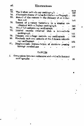
xii Illustrations
nG'
PAQH73. The Dufour cathode ray oscillograph . . . 14274. Alternative forma of tubes for Dufour oscillograph . 14876. Record of the current In the primary of an induc-
tion coil ....... 14676. Record of pressure variations in a 'fringing arc
obtained with a Dufour oscillograph . . 14677. Wood hot-cathode ray oscillograph . . . 14678. Typical records obtained with a hot-cathode
oscillograph 15179. Johnson low-voltage cathode ray oscillograph . 15880. Electrode unit and cathode of the Johnson cathode
ray oscillograph ...... 16481. Diagrammatic representation of electrons passing
through rarefied gas ..... 167
TABLESI. Comparison between undamped and critically damped
oscillographs ....... 80
OSCILLOGRAPHSCHAPTER I
FUNDAHHNTAL PBINOIPLES
The Name and Invention of the Oscillograph. Thename "
oscillograph"was first adopted by Blondel to
denote an instrument for indicating the instantaneousvalue of an electric current.
Almost any instrument which accurately indicatedthe current flowing in a circuit could be used to showthe instantaneous value of an electric current if thelatter changed, very slowly from one value to another,but when the changes are extremely rapid a veryrestricted choice of instruments is available.
The oscillograph is concerned chiefly with the
graphic representation of very rapid oscillations, andthe name might perhaps have been chosen so as toindicate the chief application of the instrument.The oscillograph, like so many other instruments,
is a development springing from a need; nevertheless,
the work of Blondel was so outstanding, firstly in
indicating the conditions to be fulfilled and secondlyin perfecting an instrument, that it is only fair thathe should be hailed as the inventor. On the otherhand Duddell, starting with the bifilar type of instru-
ment first suggested by Blondel, displayed so muchskill and ingenuity in perfecting this type that it prac-tically displaced the use of the moving iron typechiefly used up to that time by Blondel.

2 Oscillographs
Other investigators have devised special oscillo-
graphs and the references given in the Bibliography(p. 162) should be consulted by those specially inter-ested in the subject, as it is outside the scope of the
present work to give anything in the nature of adetailed historical resume.
Theory and Principle of Working. To study the
theory and principle of working of an oscillograph it
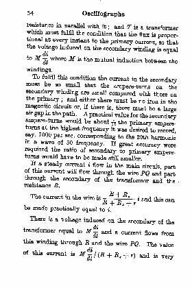
a is best to take the simplestcase and for thia purpose the
Einthoven galvanometer (or
oscillograph) may be con-
sidered. The essential fea-
tore of this instrument is a
g stretched conducting fibre or
wire placed in a strong mag-netio field. The current to
be indicated is sent along the
A MAGNETIC FIELD. wire is indicated by somesuitable means.
If, in Fig. 1, ab is the stretched wire, and if it beassumed that there is a strong field across the wirefrom the observer into the plane of the paper, thenthere will be a force on the wire at every point tendingto make it more towards the left when a current is
flowing in the direction shown by the arrow, from bto a.
Every force, however, is balanced by an equal andopposite one, and, in the present case, the force dueto the interaction of the conductor carrying thecurrent with the magnetic field is balanced by theresultant of three other forces, These forces are

Fundamental Principles 3
1. The control force due to the tension in the wire.
This acts to bring the wire back to the central posi-tion where the tension is least that is a straightline between the points a and b. For small deflec-
tions the control force can be taken as proportionalto the displacement of the wire from its central
position.
2. The inertia force, equal to the mass times theacceleration. That is, the rate at which the velocityis changing multiplied by the mass gives the force in
absolute units. If the velocity is increasing, theinertia force is opposing increase of velocity. If the
velocity is decreasing, the inertia force is opposing thedecrease in the velocity.
3. The Motional force due to the movement of theelement through the surrounding medium. Thisforce always acts in the opposite direction to whichthe wire, or the element of the wire, is moving, andits magnitude is roughly proportional to the velocityand to a coefficient which is determined by the fluid
employed, the section of the wire and the nature of
the surrounding enclosure of the wire.
From the consideration of the above rules it is
evident that, if forces (2) and (3) could be made quitesmall compared with (1), then they could be neglectedand we would have the one result that the force dueto the interaction of the current and the magnet field
would be opposed by the equal control force, but thecontrol (or restoring force) acting on the wire is pro-portional to the displacement. Therefore, for this
particular condition, the displacement would be pro-portional to the current flowing, and if this displacementoould be observed or recorded, it would give a means
4 Oscillographs
of determining the strength of the current at everymoment.
The greater the tension on the wire the larger is theforce due to the control, and the more rapid the
changes in the current whioh the wire is able toindicate accurately.
It will be seen later that an oscillograph withoutany added damping, apart from the natural dampingof the wire itself, can indicate very accurately periodicalternating current of a frequency, one-tenth thenatural frequency of the oscillograph.On the other hand, no matter what the control
force may be, if the rate of change of the current is
very rapid the inertia forces will also be relativelylarge and will cease to be negligible. If there is acurrent switched on instantaneously then the wirewill have a large velocity imparted to it and thekinetic energy stored in the wire by virtue of this
velocity will be spent in backward and forward move-ments of the wire until the whole energy is dissipated,just as the impulse given to a pendulum is spentin backward and forward swings whioh graduallybecome less until the pendulum stops at the midposition.
Conversely, if there is a steady current flowing inthe wire producing a steady deflection, and the cur-rent is suddenly stopped, the tension on the wire will
give it a high velocity whioh will start free vibra-tions and the duration of these vibrations will dependonly on the Motional forces whioh damp down themotion.
In both these last oases where there are free vibra-tions of the wire, apart from the original force that
Fundamental Principles 5
produced them, the displacement of the wire at anyinstant is no indication of any current value.Such free vibrations should therefore not be allowed
except where their occurrence cannot produce anywrong interpretation of the results and, generallyspeaking, oscillographs are used with a large factionalor damping force owing to the extremely rapid changesof current that can take place with electricity as com-pared with say, the change that could possibly takeplace in the cylinder of a steam or gas engine, wherethe indicator performs a function akin to that of the
oscillograph for electricity.
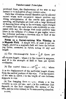
Forces on a Cnrrent-carrying Wire Vibrating ina Magnetic Field. A simple wire, of mass m per cm.length, placed in a magnetic field will have the follow-
ing forces, measured in dynes, acting on any unitlength
(1) The electromagnetic force = B dvhes per10 J *
centimetre length ; where % is the current in amperes,and B is the strength of field in lines per squarecentimetre.
2
(2) The control force = - AT ?L = _ kA; where
A is the displacement of the particular length chosenfrom the central position of the wire. T is the tensionof the wire in dynes, Z is the length of wire betweensupports in cms.
(3) The damping force = -p v
; where v is thevelocity, in cms. per sec., and p is the coefficient thatdepends on the fluid employed, the section of thewire, and (to some extent) on the surrounding chamber,
8 (6397)
6 Oscillographs
(4) The inertia force = - am;
where a is the
acceleration in cms. per seo.i and m the mass per unit
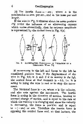
length.If the wire in Fig. 2 vibrates about its mean -position
PQ under the influence of an alternating current
which varies sinusoidally, then its extreme amplitudeis represented by the dotted lines in Fig. 2 (a).
pA A
JU
H'ff
\\f'I
()FIG. 2. ILLUSTRATING COITOITIONB ov VIBRATION OF A
STBBTOHBID WISH PQ
If movements to the left and forces to the left beconsidered positive then, if the displacement of thewire in Fig. 2(6) is A and if it be moving to the left,
the control force at that moment is -JfcA, i.e. it is
acting to bring the wire to rest or to stop the move-ment.
The Motional force is -pv, where v is the velocity,
and also acts against the movement. The inertia
force is acting in the direction of motion, tending to
prevent change of motion, and is equal to the rate at
which the velocity v is changing and, since the velocityis decreasing, the force is positive and is equalto -
(- am) or am. Therefore the inertia force is
opposing the control force and, at that instant, the
Fundamental Principles 7
damping force is in the same direction as the controlforce.
When the wire reaches the extreme position to theleft, shown in Fig. 2(c), the control force is still actingtowards the right and has its maximum value as thedisplacement is a maximum. The damping is zero atthat instant aa the velocity is zero. The inertia forceIB a maximum, as the rate at which the velocity is
changing is a maximum, and is acting in the samedirection as in Fig. 2(6), i.e. in the opposite directionto the control force.
When the wire arrives on its return journey at themean position, shown in Fig. 2(d), the velocity is amaximum and the rate at which the velocity is
changing is zero, therefore the inertia force is also zeroAs the wire is in the central position there is no restoringor control force on the wire, so the control is also zerT-but, as the velocity is a maximum, the damping forceis a maximum and now acts towards the left and ispositive as the velocity is negative.When the wire arrives at the' position shown in
J*g. 2(6), and is moving towards the right, the (nega-tive) velocity is growing less and, a* the force of
fZf1
^r868,th\ clla^e of ^locity, the inertia
force acte towards the right and is therefore a nega-tive force The control orrestoring force is towardsthe left and is therefore positive, while the dampingforce is also towards the left and positive as it tends to
stop thevmovement.If this reasoning be followed, step by step, it will beseen that for a wire
vibrating under the influence of ao a
ZSrr? dternatinS ourrent * inertia force and
the control force always act in opposite directions-thai
8 Oscillographs
is, the control force is a maximum when the inertia forceis a maximum and they are opposite in phase. To findtheir resultant it is only necessary to subtract the value
of one from the other.
On the other hand, the damping force is a maximumwhen the control force is zero and it can only be com-
pounded with the control or with the inertia force
vectorially to give effective values.
For instantaneous values, the forces can all be added
algebraically thus, for the position shown in Pig. 2(6) :
If i is the instantaneous value of the current then
i
B - kA -pv
- am = o
since these are the only forces that can act on the
wire and the sum. of them must be zero at any moment.If the changes taking place in the current be very
slow then the terms pv and am are very small and can
be neglected when B = &A, and the deflection A =
t/10&. The condition that A = i/Wk is only true for
steady currents or for conditions where the rate of
change is comparatively slow.
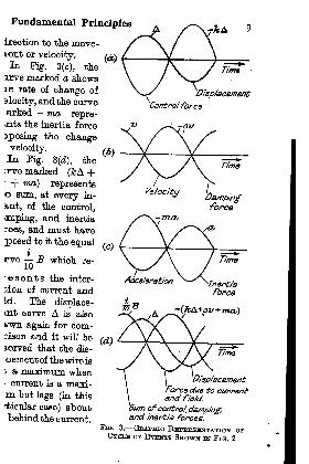
Graphic Representation of Conditions. Fig. 3 is a
graphic representation of the cycle of events repre-sented in Fig. 2. In Fig. 3(a) the sine curve markedA shows the displacement plotted against time. Thecurve marked - &A shows the control force acting at
every point in the opposite direction to the displace-ment.
In Fig. 3(6) the curve marked v represents the rate of
change of the displacement or the velocity, and - pv is
the damping or Motional force acting in the opposite
Fundamental Principles
ireotion to the move-lent or velocity.In Kg. 3(c), the
irve marked a showsle rate of change of
slooity, and the curve.arked - ma repre-'nts the inertia force
^posing the changevelocity.In Fig. 3(d), theLrve marked- (kA +1
-f- ma] represents
sum, at every in-
a.nt, of the control,
.mping, and inertia
c*oes, and must have
posed to it the equal
rve B which re-
esents the inter-
bion of current andId. The displace-nt curve A is also
i/wn again for oom-dson and it will beserved that the dis-
oement of the wire is
; a maximum when' current is a maxi-m but lags (in this
"tioular case) about"behind the current.
Velocity L . ^yDampingforce
^ TflCL
DisplacementForce due to current
j
and f/e/d.
Sum ofcontrol, da/np/ng;and inertia forces.
FIG. 3. GRAPHIC REPBESEINTATTON offCYOLB OF EVHNTH SHOWN IN FIG. 2
10 Oscillographs
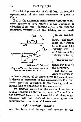
Vectorial Representation of Conditions. A vectorial
representation of the same conditions is given in
Fig. 4.
If A be the maximum displacement, then the maxi-
mum velocity is 2-n/A where / is the frequency of
vibration of the wire. Writing 2?r/=
a>, we have the
maximum velocity = coA and leading by an angle
- on the displace-
\ ment. The maxi-
mum acceleration
is co times the
velocity and is
co2A and leads the
velocity vector by77
-. The upper por-
VftA-TTw^AP+^A)* tion of Fig. 4 shows
FIG. 4. VEOTOB RHPBDSHNTATTON OF vulB condition.CONDITIONS DHPIOTHD IN FIG. 2 The force dia-
gram is shown in
the lower portion of the figure where the control forceis drawn in opposition to the displacement, the Mo-tional force in opposition to the velocity, and theinertia force in opposition to the acceleration.
This diagram shows how the control force yfcA is
always opposed by the inertia force w 2Am and howthe difference between the forces &A and co
2 Ara com-pounded with the frictional force pcoA gives theresultant maximum internal force equal to
and this force must be equal and opposite to the
Fundamental Principles n
maximum external force S. The lead of the current
on the displacement is the angle a.
Effect of Frequency. It is evident from Pigs. 3and 4 that the resultant maximum internal force andtherefore the value of the current will not be constantfor a given deflection A but will vary with the fre-
quency. The larger the control force, compared withthe damping and inertia forces,the less the resultant internal *_ >force will vary with a given
**
change of frequency, and there-
fore the less the change in the ^value of the alternating currentto give an amplitude equal toA and the smajler the angle a FIG. B.-APPUHD FKH-between the current and the QOTINOT = BBSONAITT
disnlaneniftnt FajaQinnNOY or THEDisplacement. Wma . CoNTBOL PoBOH
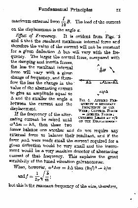
If the frequency of the alter- = IN^ETTA FOBOH ;
rating current be raised until S^SnSSiSSSo>
2Am = &A, then these twoforces balance one another and do not require anyexternal force to balance their resultant, and if theforce peoA were made small the current required for a
given deflection would be very small and the instru-ment would be a very sensitive detector of alternatingcurrent of that frequency. This explains the greatsensitivity of the tuned vibration galvanometer.
When, however,ju2Ara = &A then (2rr/)
a = k/m
mbut this is the resonant frequency of the wire, therefore,

12 Oscillographs
when the frequency of the alternating current is the
same as the frequency of the wire, there is no in-
ternal force apart from the damping and the current
7T
leads by - on the displacement. This is shown in2i
Pig. 5.
If the applied frequency be raised above the resonant
frequency of the wire then eu^A is greater than kA,
PIG. 8. APPLIED FBSQTJHNOY EXCEEDS RHSONANT irBBQUBNOYOP THB WiEUD ; OUBHHNT LEADS BY MOBB THAN
7T/2 ON TKB DlHPLAOBttEHINT
and the condition of affairs is as shown in Fig. 6. Theangle a between the current and the displacement is
7T
now greater than - and approaches TT as the frequency
becomes higher.
Magnitude of the Prictional Force ; Damping. Sofar nothing has been said about the magnitude of theMotional force as compared with the control force.
As the control force is independent of the frequency,and the fractional force varies with the frequency, the
magnitude of the Motional force has to be defined atsome definite frequency and from that the coefficient
p deduced.
The maximum value of the Motional force is
. opA where A is the maximum displacement.

Fundamental Principles 13
/ If copA were made equal to &A when A =/ then at this, the resonant frequency of the wire
a>p= k
, k kand p = =
2
or p* = km.
At the resonant frequency of the wires, since thecontrol and inertia forces are equal and opposite, the
only internal force is the frictional force which atthis frequency has been made equal to the controlforce. This has to be balanced by the force due tothe current jn the wire, therefore, the current requiredwill just have the same value as would be required toovercome the control force if the frictional and inertiaforces were entirely absent, and the maximum dis-
placement A due to a current I sin CD will be equal tothe steady deflection due to a current /. That is,the deflection for a very low frequency and for theresonant frequency of the wire will be the same.
This would correspond, in Fig. 4, to having all thevectors kA, mo> 2A and pcoA of equal length at theresonant frequency of the wire.
This value of the frictional force has some meritsin practice, and has been advocated as it gives prac-tically the correct amplitude of deflection for moder-ately low frequencies, and for frequencies near theresonant frequency of the wire.
In general practice, however, the Motional force
is made twice as great, i.e. p = 2 Vfon = 2(om, so as tomake the instrument what is known as
"critically
damped"
or"dead beat." Under these conditions,
J4 Oscillographs
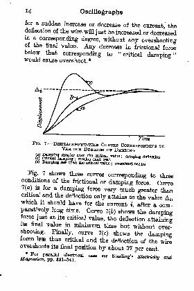
for a sudden increase or decrease of the current, thedeflection of the wire will just be increased or decreasedin a corresponding degree, without any overshootingof the final value. Any decrease in frictional forcebelow that corresponding to "critical damping"would cause overshoot. *
TimaFlG. 7. DlSPLAOHUOINT-TIMH CTTBVHS CoBHBlffiE>ONDrNG TO
VARIOUS DHGBBLHS OF DAMPING
ie) Damping lees than the critical value
; overshoot oocuiu
Fig. 7 shows three curves corresponding to threeconditions of the frictional or damping force. Curve7(o) is for a damping force very much greater thancritical and the deflection only attains to the value A,,which it should have for the current i, after a com-paratively long time. Curve 7(6) shows the dampingforce just at its critical value, the deflection attainingits final value in minimum time but without over-shooting. Finally, curve 7(c) shows the dampingforce less than critical and the deflection of the wireovershoots its final position by about 37 per cent.
"B " StarUng'
8

Fundamental Principles 15
In Fig. 7(c) the wire does not come to rest when it
returns to the value A { , corresponding to the current i,
but oscillates about that value. The rate at whichthese oscillations die away is so rapid, for any prac-tical value of damping, that it is only the first over-shoot that is observable. Thus, if the first overshoot
FIG. 8. SHOWING RAPID CESSATION OP OSCILLATIONSCONSEQUENT UPON OVBBSHOOTING
represents 3 per cent of the total deflection, the over-shoot on the opposite side of the final position is 3 percent of 3 per cent, or less than one in a thousand. Evenwhen the first overshoot is as much as 20 per cent,
corresponding to about half critical damping, thesecond overshoot (towards the zero value of current)is only 4 per cent, and the third is less than 1 per cent.
This is shown in Fig. 8 where, in the left-hand dia-
gram, the time base is shown to a very large scale.
Thus, if the wire had a natural frequency of 6000 persec. when damped, the complete oscillation occupiesa distance of about 2.5 cms. in the left-hand diagram,Fig. 8, and takes ^ViT of a sec. In practice the timebasis is seldom greater than 400 cm. per sec., and the

16 Oscillographs
graphic representation of the curve to this usualscale is shown in the right-hand diagram, Fig. 8. Itis seen that the overshoot, instead of being a roundedcurve, now appears as a very sharp peak and, in a timeequal to^^ sec., the deflection has practically attainedits normal value.
It will he seen from the above considerations that anoscillograph, to give a reasonably true record, musthave (a) its natural frequency high compared with the
frequency it is desired to observe; and (6) it must be
strongly damped or braked by a Motional force atleast equal to the control force at its own natural
frequency, when it is called upon to record suddenchanges in current.
Motion and Dynamics of a Vibrating Uniform Wire.There are some fundamental relations of a simple
-f
FIG. 9. MOTION nr A VrBBAnwa UNTPOBM Wma isEVUBYWHHBS! PHttPHNDICDLAB TO THB MHAN
POSITION
vibrating wire which it is desirable to establish. If awire be stretched between two points P and Q, Fig. 9,and be made to vibrate between the extreme positions,Pd&iSi Q and Pd&ifi Q then, if there is no longitu-dinal movement along the wire, the path of move-ment of every point on the wire will be at right anglesto the mean position of the wire P d ef Q, and a pointon the wire, say e, .will have a path et e e a .
If the displacement of the wire at the centre = A andif it be assumed for the present that the curve of the
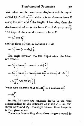
Fundamental Principles 17
wire when at its maximum displacement is repre-
(7T\),where x is the distance from P
L J
along the wire and I the length of the wire, then the
displacement at (a; + dx) from P = A sin (x + dx) -.I
The slope of the wire at distance x from P.IT TT= Ar- cos x=-
;
I If
and the slope of wire at distance x + dx
= A- cos (a; + dx,) .
I I
The angle between the two slopes when the latter
are ymp,n
A 7T(
TT 7T)= A-
]cos x - - cos (x + dx)
- 1
I(
I I)
f.
1^(
T IT 7T . 77. IT)= A-
jcos a; - - cos x-- cos dx- + sm a;- sin dx - 1
i[
I I I I I \
When da; is so small that cos da;- = 1 and sin da;-l I
j *= dx-L
In Fig. 10 there are tangents drawn to the wire
corresponding to the ordinates at x and x + da;, andshown as T 1 and T z ;
the angle between these tangentsis that given above.
There is a force acting along these tangents equal to

i8 Oscillographs
the tension T in the wire, and the resultant of thesetwo tensions is the foroe accelerating the element ofthe wire dx to the mean position.When two equal forces act at a small angle to each
other the resultant can be shown to be equal to one of
FIG. 10. ILLUSTRATING THB CONDITIONS IN A SHOBTELEMENT OP A VIBRATING UNIFOBM WEBB
the forces times the angle between them. In theabove case the force on the element of the wire will be
-)asin a dynes . m
*
The mass of the wire is m per unit length, hence themass of length dx = mdx.
The acceleration =mdx
and the displacement of the wire = A sin x^-L
m 2V IM '(2
)
Where ml = M = total mass of the wire.

Fundamental Principles 19
From eqn. (1), the restoring force on unit length ofa stretched wire at any portion of its length is
/7TTl\*
but A sin x- is the displacement at that portion,
therefore the restoring force per unit length is
2
times the displacement.
From eqn. (2), the frequency of vibration of the
1 [~TU2Y Iflif
whio]l is foe usual expression for a
stretched wire.
In the above it has been assumed that the resultantforce acts at every point on the wire directly at rightangles to the mean position and this is generally verynearly true for any practical amplitude of vibration.
It has also been assumed that the displacementcurve is sinusoidal and it is evident that this must betrue if there is no control on the wire apart from thetension in the wire itself. Any departure from asinusoidal curve would mean that portions of the wirewould be experiencing a greater or smaller force thanwould be required to give them the necessary accelera-tion for the same frequency at every point on thewire. As long as the wire vibrates as a whole and doesnot give out overtones, and as long as the rigidity ofthe wire is not appreciable, compared with the forcedue to the tension, the displacement along the wire is
sinusoidal.
Conditions of Vibration in a Loaded Wire. Whenthe wire is loaded in the middle a new condition of
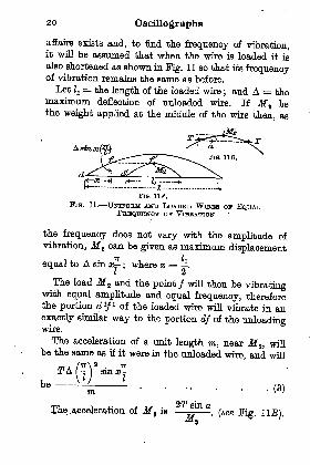
20 Oscillographs
affairs exists and, to find the frequency of vibration,it will be assumed that when the wire is loaded it is
also shortened as shown in Fig. 1 1 so that its frequencyof vibration remains the same as before.
Let Zj= the length of the loaded wire
; and A = themaximum deflection of unloaded wire. If M t bethe weight applied at the middle of the wire then, as
<*(' fr ,
tf "*l<*^-
1' -^
FIG. IIA.
Fio. 11. UNTB-ORM AND LOADHD WIRES OF EQUALOF VIBRATION
the frequency does not vary with the amplitude of
vibration, M 2 can be given as maximum displacement
equal to A sin x; where x = .
I 2
The load M s and the point / will then be vibratingwith equal amplitude and equal frequency, thereforethe portion d 1
/1 of the loaded wire will vibrate in an
exactly similar way to the portion df of the unloadingwire.
The acceleration of a unit length m, near M%, willbe the same as if it were in the unloaded wire, and will
.-- - -(3)
23ration of M is
M*rm_ i j_- P -MM- 2>T sin aThe .acceleration of M* is
, (see FieM **"
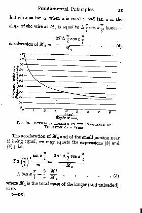
Fundamental Principles 21
but sin a = tan a, when a is small; and tan a or the
slope of the wire at M z is equal to A ^ cos x -, henceL I
acceleration ofM a=
^ (A\~M' ' * *
\ I^to
0-1
-
4 BLoad.
FlG. 12. ESTTHOT OP LOADING ON TUB PBnQTJDNOY OPVIBRATION OP A WIHB
The acceleration ofM t and of the small portion nearit being equal, we may equate the expressions (3) and(4); i.e.
TT 2 M i
..tana; = -.M a..... W
where Jf x is the total mwe of the longer (and unloaded)
8 (5897)

22Oscillographs
For different values of -i, x can be found, and"* a
2 x = the length of the shorter wire. Knowing this,the weight of the short wire can be found and it fethe ratio of the added weight Jft to the weight of theshort wire that is called the loading.
Against this loading it is only necessary to' plot theratio IJl since the frequency of vibration of an unloadedwire is inversely proportional to the length, and sucha curve is shown in Fig. 12.
It can be shown that, where the loading is small
Frequency of loaded wire = Weight of wire
Frequency of unloaded wire~
Weight of wire + loadThus, for a loading weight equal to 20 per cent of
the weight of the wire this gives a frequency of vibra-tion equal to 83-3 per cent of the frequency of theunloaded wire, whereas the true value is 84 per centnearly.
From the two equations (2) and (6) it is possible toobtain by deduction the frequency of any stretchedwire when loaded, or of a bifilar system with a mirrorplaced across it, as long as the torsional forces aresmall compared with the tensional forces.

CHAPTER nTYPES OF OSCILLOGRAPHS
Einthoven String Oscillograph (or Galvanometer).This instrument was used originally at lower thanwhat might be called osoillographio frequencies, butwith improvements in
its construction it hasbeen used for higherand higher fre-
quencies. It consists
essentially of a con-
ducting fibre or wire
stretched in a strong
magnetic field andd i f e r s nothing in
principle from the
simple wire we havebeen considering inthe previous chapter. Fia - 13 - DIAGBAMMATIO
In praotice, the fibre ^Si o^iSST"is made very fine, a
diameter of 0'02 mm. or less being common when it is
made of silver or tungsten and a diameter of 0-002 to0-003 mm. when it is made of silvered glass.In Fig. 13 is shown a diagrammatic view of a fibre
mounted in a strong magnetic field, with one systemof lens for strongly illuminating the fibre from somesuitable source of illumination, such as an arc lamp,an over-run
"gasfilled
"lamp, or ft Pointolite lamp,'
962
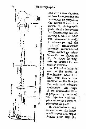
Oscillographs
and with, a second systemof lens for observing the
movement or projectingthe movement on to ascreen or photographicplate. Such a lens systemfor
illuminating and ob-
serving a fibre of 0-003mm. diameter is reallya microscope, and the
optical arrangementsnormally recommendedby the Cambridge Instru-
"ment Co. are shown in
Kg. 14 where the mag-nets are omitted for thesake of clearness.
A Pointolite lamp is
used as the source of
iHumination and thelight from this is con-
centrated on the fibre bythe main and substagecondensers. An imageof the illuminated fibre
is projected by means ofthe objective and eye-piece on to the screen or
photographic plate.In the absence of any
further lenses this imagewould appear as a bright
patch with th

Types of Oscillographs 25
fibre showing as a vertical black line across it as shownin Fig. 15(a). In order that very rapid movements ofthe fibre may be observed, this vertical black linemust be reduced practically to a point and this is doneby two cylindrical lenses with their axes horizontal.
(a) (b) (C )
15.-ILLUSTRATING THB REDUCTION OP THEOF A FTBHE TO A POINT
The first cylindrical lens reduces the circle of lightto an ellipse as shown in Fig. 15(6), and this is reducedby a second cylindrical lens to a bright illuminatedline, shown dotted in Fig. 15(c), with the fibre showingas a black spot on this line.
Movements of the fibre result in proportional move-ments of the black spot along the illuminated line, andthe lens system is such that the movement of thefibre is magnified 500 to 600 times on the plate.With any particular fibre, the sensitivity of the
instrument for steady current conditions dependssolely on the tension and, as the mass per unit lengthis very small, the tension need not be high for moderatefrequencies.
Thus, for a silver wire 0-02 mm. in diameter to havea frequency of 100 per sec. when its total length is10 cm. we must have a tension given by_
T = 4
where M is the total mass of the wire= 3-3 x 10~4 grams.

26Oscillographs
T = 4 X 10* x 10 x 3-3 X 10-* dynes.= 132 dynes = 0-135 gram.The force,on unit length at the centre of the wire is
where A = displacement of the wire, in cm.T = tension, in dynesI = length of wire, in cm.i = current, in A
and B = strength of magnetic field, in lines persq. cm.
Suppose the deflection on the screen is 1 mm. andthe magnification is 600, then the actual movement ofthe wire is ^^ cm. Hence
and, if B = 20,000 lines per sq. cm., then
i= 1-075 x 10- fl A.
It is seen, therefore, that such an instrument givesroughly 1 mm. deflection for a current of l^iA whenthe tension is adjusted to give a natural frequencv of100 per sec.
y
The damping or frictional force due to the move-ment of the wire in air is, however, too small to makethe instrument anywhere near dead beat and it is
only silvered glass fibres of about 0-0026 mm. diameterthat are
critically damped or dead beat at this fre-
quency.There are many oases in practice where an instru-
ment of the above sensitivity is very useful, even atcommercial frequencies, as the errors introducedowing to the frequency of the measuring oscillograph

Types of Oscillographs 27
oan be compensated, or the results corrected, as shownin Chapter IV.
To raise the natural frequency of the above instru-ment to 1000 per sec. would require the tension to beincreased to 100 times the former vaLae*, i.e. to 13-6
grams, which would be over the safe^stress for thissize of silver wire.
The length of the fibre oan be shortened withoutloss of sensitivity and without altering the frequencyof vibration as, from the equations already given, it
can be shown that the current required to give adeflection of A cm. is
407T* Am/ a i A.Jo
where m is the mass per unit length of the wire.Therefore the length of the wire does not affect the
sensitivity theoretically, as long as the portion of the
magnet out away to accommodate the lenses of the
microscope does not form an appreciable portion ofthe length of the fibre.
In practice, when the fibre is short, this inoperativeportion of the fibre becomes very important andlengths shorter than 5 cm. are seldom used. Withthis length frequencies of 1000 are quite possible, andeven frequencies of 2000 per sec. with phosphorbronze wire.
To obtain a photographic record of the movementof the dark image made by the fibre it is necessary tomove a photographic plate or film at right angles tothe illuminated line along which the dark image of thefibre moves and to exclude from the plate all otherappreciable sources of light. A special camera is used
28 Oscillographs
to give an even speed to the plate and to out off stray
light.
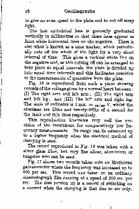
The last cylindrical lens is generally graduatedvertically in millimetres so that these lines appear as
faint white horizontal lines on the negative. There is
also what is known as a time marker, which periodic-
ally outs off the whole of the light for a very short
interval of time. This gives a vertical white line onthe negative and, as this cutting off can be arranged to
take place at equal intervals, the plate is divided upinto equal time intervals and thin facilitates precisionin the measurements of quantities from the plate.
Fig. 16 is reproduced from such a plate showingrecords of the voltage given by a normal heart between :
(I) The right arm and left arm; (II) The right arm
and left leg ;and (HE) The left arm and right leg.
The scale of ordinates is 1 mm. = ^5^ V, whilst theabscissae are fifths and twenty-fifths of a second for
the thick and thin lines respectively.This reproduction illustrates very well the pre-
cision of the instrument for comparatively low fre-
quency measurements. Its range can be extended upto a higher frequency when the electrical method of
damping is used.
The record reproduced in Fig. 16 was taken with asilver glass fibre, but very fine silver, aluminium or
tungsten wire can be used.
Fig. 17 shows two records taken with an Einthoven
galvanometer where the frequency was increased up to500 per sec. This record was taken on an ordinarycinematograph film running at a speed of 200 cm. persec. The first portion (a) is a record of switching ona current when the damping is that due to air only.

X Ir _ '
irv; -r-

30 Oscillographs
The second portion (6) is a record of switching off acurrent when the instrument is damped by connectinga resonant shunt in parallel with it as described later.It will be seen that the free vibrations are wiped outin the second case.
(a) With at dumping alone(j) with damping by a parallel-
connected resonant ahmtFIG. 17. RBOOBDS op MAKING AND BHHAKINQ A Craouir
USING AN ElNTHOVHN GALVANOMHTHB
Blondel Bffilar Oscillograph. Blondel showed thatwith a moving coil galvanometer, having a coil sus-pended by two wires in tension, the sensitivity, at agiven frequency, was increased as the number of turnson the coil waa reduced, and reached a maximumwhen the
"coil
"reached its elemental form of a
single loop of wire stretched in a magnetic field withan indicating mirror placed across the loop.Such a galvanometer or oscillograph is shown in
Pig. 18 where a loop of wire abed is shown stretchedacross two bridge pieces and placed in the field due tothe magnetic N.S.A current passed through the loop, up on one side and
down the other, causes one wire to be deflected awayfrom the observer and the other towards the observer.
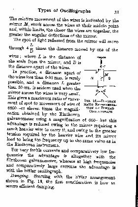
Types of Oscillographs 31
The relative movement of the wires is indicated by themirror M, stuck across the wires at their middle pointand, within limits, the closer the wires are together, thegreater the angular deflections of the mirror.The spot of light reflected from the mirror will move
through 4 - times the distance moved by one of the
wires; where L is the distance of
the scale frqin the mirror, and D is
the distance apart of the wires.In practice, a distance apart of
the wires less than 0-30 mm. is rarelypossible, and a distance L greaterthan 50 cm. is seldom used when themirror across the wires is very small.This gives a maximum ratio of move-ment of spot to movement of wire of6600 or eleven times the magnifi-cation obtained by the Einthoven
Fia. 18. DIAQBAM-
TION OB" BlBTLABOSCILLOGRAPH
galvanometer using a magnification of 600 but this
advantage is reduced owing to the mirror requiring amuch heavier wire to carry it, and owing to the greatertension required by the heavier wire and its mirrorload to bring the frequency up to the same value as inthe Einthoven instrument.For very feeble currents and comparatively low fre-
quencies the advantage is altogether with theEinthoven galvanometer, whereas at high frequenciesand comparatively large currents the advantage iswith the bifilar oscillograph.
Damping. Starting with the bifilar arrangementshown in Pig. 18, the first consideration is how tosecure efficient damping.
32 Oscillographs
For low frequencies there is no difficulty, as immers-ing the wires and mirror in oil of a medium viscositycan be arranged to give aU the damping required.For high frequencies, however, the damping force
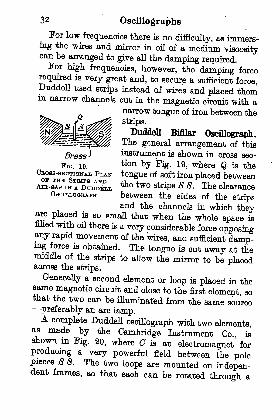
required is very great and, to secure a sufficient force,Duddell used strips instead of wires and placed themin narrow channels cut in the magnetic circuit with a
narrow tongue of iron between the
strips.
Duddell Bifllar Oscillograph.The general arrangement of this
Brass J instrument is shown in cross sec-
Fio. 19.tion by Kg. 19, where Q is the
CBOSS-SBOTIONAL PLAN tongue of soft iron placed betweenop THE STBTPS AND -L , , . r
AIH-QAP IN A DUDDELL the two stnP8 s s - The clearancebetween the sides of the stripsand the channels in which they
are placed is so small that when the whole space isfilled with oil there is a very considerable force opposingany rapid movement of the wires, and sufficient damp-ing force is obtained. The tongue is cut away at themiddle of the strips to allow the mirror to be placedacross the strips.
Generally a second element or loop is placed in thesame magnetic circuit and close to the first element, sothat the two can be illuminated from the same source
preferably an arc lamp.A complete Duddell oscillograph with two elements,
as made by the Cambridge Instrument Co., isshown in Fig. 20, where C is an electromagnet for
producing a very powerful field between the polepieces S S. The two loops are mounted on indepen-dent frames, so that each can be rotated through a
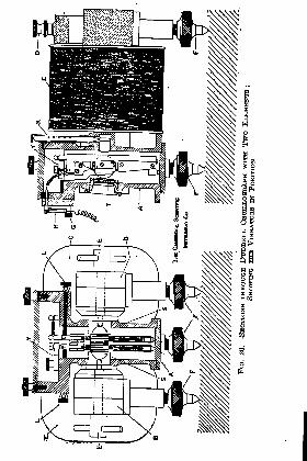
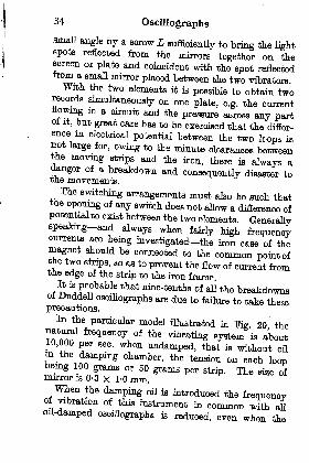
34 Oscillographs
small angle by a screw Lsufficiently to bring the light
spots reflected from the mirrors together on thescreen or plate and coincident with the spot reflectedfrom a small mirror placed between the two vibrators.With the two elements it is possible to obtain two
recordssimultaneously on one plate, e.g. the current
flowing in a circuit and the pressure across any partof it, but great care has to be exercised that the differ-ence in electrical potential between the two loops isnot large for, owing to the minute clearances betweenthe moving strips and the iron, there is always adanger of a breakdown and consequently disaster totne movements.The switching arrangements must also be such that
the opening of any switch does not allow a difference ofpotential to exist between the two elements. Generallyspeaking and always when fairly high frequencycurrents are being investigated the iron case of themagnet should be connected to the common point ofthe two strips, so aa to prevent the flow of current fromthe edge of the strip to the iron frame.
^^?^bable *hat nme -tent^ of all the breakdownsof Duddell
oscillographs are due to failure to take theseprecautions.
In the particular model illustrated in Pig 20 thenatural frequency of the
vibrating system 'is about10,000 per sec. when undamped, that is without oilin the damping chamber, the tension on each loopbeing 100 grams or 50 grains per strip. The size ofmirror is 0-3 x 1-0 mm.When the damping oil is introduced the frequenovof vibration of this instrument in common with aU
oil-damped oscillographs is reduced, even when the
Types of Oscillographs 35
visooaity of the oil ia much less than would giveefficient damping, and apart altogether from the loweringof the frequency due to damping.The reason for this is that a body in motion in a
fluid has energy stored in virtue of its velocity equalto where ma is the mass andv, the velocity of the body itself
; m, is the mass andu a the velocity of any small portion of the fluid put inmotion by the movement of the body ; and } Z m. v aIB the total energy stored in all the fluid by virtue ofits motion.
In practice it is found that the effective frequencymay be reduced by as much as 33 per cent, corre-sponding to an increase of effective mass of about 130per cent, and as the specific gravity of the oil is aboutone-tenth that of the phosphor bronze strips, thevolume of oil put in motion by the strips is somethirteen times the volume of the strips themselves.
This reduction of effective frequency, to 0-66 of thefrequency when not immersed, reduces the "
factor ofmerit
"of the instrument to 43 per cent of what it is
undamped and, in addition it introduces an uncer-tainty as to what should be called the "natural"frequency of the instrument.
Superimposed on this uncertainty is that due to thechange of viscosity of the oil caused by change oftemperature; this change of viscosity alters thedamping coefficient so that the theoretical correctionof the record from an oil-damped instrument is a matterof doubt.
In practice a correction for the magnitude of thedeflection of an oscillograph can always be obtainedif there is a high frequency alternator available for if

36 Oscillographs
a constant current be kept flowing through the instru-
ment, and the frequency of the current be varied thena curve can be drawn showing the factor at each fre-
quency by which the deflection must be multipliedto make it equal to the deflection at very low
frequencies.The correction for phase or time displacement of the
deflection from the current producing it is not so easyto determine. If, however, a second oscillograph beavailable from which the damping oil can be removedthen, if the oscillographs have the same current
passed through them in series, their records beingtaken on the same plate, the phase displacement ofthe damped record can be compared with the un-
damped at the whole range of frequency of the instru-
ments, and as the phase displacement of the undampedinstrument can be easily calculated from its constants,the phase displacement of the record of the dampedoscillograph from the actuating current can becalculated.
It may be said, however, that for ordinary com-mercial work, where harmonics up to an absolute
frequency of 1000 per seo. are' concerned, no correctionis necessary for the above instrument at its normalfrequency.As the size of the mirror in this particular type of
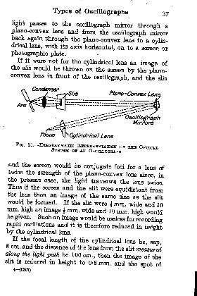
instrument is very small it is necessary to illuminatethe mirrors by means of an arc lamp, particularlywhen photographic records are to be taken. Theessential arrangement of the optical system as used forthis and most other oscillographs is shown in Fig. 21.The light from an arc lamp is fooussed so as to illumin-ate strongly a narrow vertical slit, From this slit the
Types of Oscillographs 37
light passes to the oscillograph mirror through aplano-convex lens and from the oscillograph mirrorback again through the plano-convex lens to a cylin-drical lens, with its axis horizontal, on to a screen orphotographic plate.
If it were not for the cylindrical lens an image ofthe slit would be thrown on the screen by the plano-convex lens in front of the oscillograph, and the slit
n̂ano-Convex Li
f"Focus ^Cylindrical Lens
FIG. 21. DIAGRAMMATIC BospKHaBiNTA'noN or THE OPTICALSTSTHM OF AN OSOILLOGBAPH:
and the screen would be conjugate foci for a lens oftwice the strength of the plano-convex lens since, inthe present case, the light traverses the lens twice.Thus if the screen and the slit were equidistant fromthe lens then an image of the same size as the slitwould be formed. If the slit were Jmm. wide and 10mm. high an image \ mm. wide and 10 mm. high wouldbe given. Such an image would be useless for recordingrapid oscillations and it is therefore reduced in heightby the cylindrical lens.
If the focal length of the cylindrical lens be, say,8 cm. and the distance of the lens from the slit measuredalong the light path be 100 cm., then the image of theslit is reduced in height to 0-8 mm. and the spot of
4r-(5897)
3^ Oscillographs
light on the screen is nearly a round dot when a certainamount of dispersion is allowed for.
Other Bifllar Instruments. Bifilar oscillographs ofthe same general type as the above are made by
Sy eourtety of
EPFHOT OP
Cambridge Instrument Co., Ud.
AMBBINQ^^FOBM OP A RoTABY CoNVHBTBB
Carpentier (Paris), and Siemens & Halske (Berlin)whilst three-elementoscillographs are made by the
General Electric Co. of America, and by the Westing-house Electric & Manufacturing Co. The firm lastmentioned has developed a type for use in conjunctionwith an overrun tungsten lamp. This lamp ia of thelow-voltage, high-current type with a very concen-trated filament and it is overrun by about 60 per cent

Types of Oscillographs 39of the normal voltage just at the moment of takingthe photographic record on the film. AB the lampisoverran
^evenat what is called the normal voltage, the
? ?"UBlt
?d be extremely^ ^
cent excess voltage allowed to persist. It isv, ~ m0reaseis only allowed during the time the shutter of the
camera is open, and theswitching on of the lampand the openmg of the shutter are arranged to
operate from the motor that drives the film whilst'
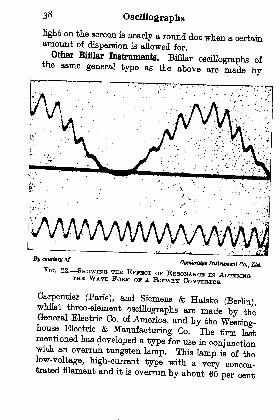
These^oscillographs also have the three elementsmsukted from each other by thin micanite sheeCIdthis is a distinct advantage.
The three reproductions shown in Pigs. 22-24 aretypical of the records obtained with a Duddell bifilarosciUograph. Kg. 22 shows the effect of resonantaltering tte wave form of a rotary converter; j23 shows the rush of current and rise of voltage at the
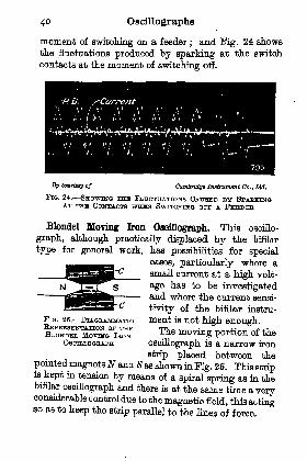
40 Oscillographs
moment of switching on a feeder;and Fig. 24 shows
the fluctuations produced by sparking at the switch
contacts at the moment of switching off.
Sy caurtetif of Cambridge Instrument Co., Ltd.
FIG. 24. SHOWING THU FLUCTUATIONS CAUSED BY SPAKKINGAT THE CONTACTS WMJUN SWITCHING OST A FBDBIIJEE
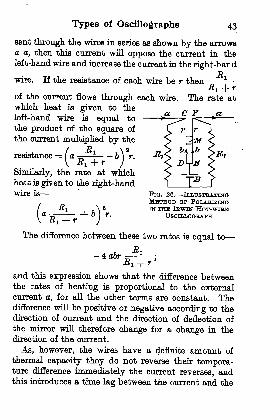
Blonde! Moving Iron Oscillograph. This oscillo-
graph, although practically displaced by the bifilar
type for general work, has possibilities for special
oases, particularly where asmall current at a high volt-
age has to be investigatedand where the current sensi-
tivity of the bifilar instru-
ment is not high enough.The moving portion of the
oscillograph is a narrow iron
strip placed between thepointed magnetsN and 8 as shown in Fig. 26. This stripis kept in tension by means of a spiral spring as in thebifilar oscillograph and there is at the same time a veryconsiderable control due to the magnetic field, this actingso as to keep the strip parallel to the lines of force.
FlG. 25, DlAGBAMMATICBJEPEESENTATION OP THHBLONDKL MOVING IKON
OSCTLLOGBAPH

Types of Oscillographs 41
There are two coils CC placed one on either side ofthe moving iron strip and with their axles at rightangles to the strip and to the lines of force. These coils
produce a field at right angles to the main field andcause a slight swing of the nmJTi field clockwise or
anti-clockwise, depending on the direction of thia newfield. The iron strip always turns to lie along theresultant field, and as long as the deflection is smallthe angular movement of the strip is proportional tothe strength of the auxiliary field, and therefore to thecurrent in the coils.
These coils can be wound with a few turns to carrya large current or with many turns to carry a verysmall current. In the latter case the current sensi-
tivity can be made very large. When the coils arewound with many turns their self-induction becomesvery large, especially with some of the finer wires now'available, but as long as a large enough swampingresistance can be introduced, as on a high voltagesystem, this is not a serious disadvantage.The deflection is indicated by a small mirror stuck
on to the iron strip and the light passes to the mirror
through the hollow front coil. Damping is by meansof oil as in the bifilar oscillograph.In practice it is necessary to use a correction curve
obtained by a high-frequency alternator as with thebifilar instrument for the reasons explained on page36, and also for the following additional reasons
(1) The effective self induction, the self capacity,and the resistance of the coils vary with the frequencyowing to the shunting effect of the capacity from turnto turn and of the capacity from the turns to the iron
;
this alters the effective impedance of the coil.

42 Oscillographs
(2) The shunting effect of the turn to turn capacityalters the effective ampere-turns on the coil for a givencurrent flowing in the external circuit.
These latter effects can be quite appreciable at thehigher frequencies but, where a correction has to beapplied, it is not of great importance what particularfactor is greatest in causing distortion. The total
percentage reduction in the higher harmonics is theimportant thing to be considered, and if this reductionbe large the magnitude of the harmonics in the wavemay be so small, compared with the fundamental,that its accurate determination is not possible.
Irwin Hot-wire Oscillograph. Up to the presentwe have been considering instruments in which thedeflection within definite limits is proportional to thecurrent and approximately in phase with it.
The hot-wire oscillograph belongs to a class in whichthe deflection is not proportional to the current flowingthrough the instrument, but the latter can be arrangedto give a record of the pressure across a circuit or thecurrent flowing in a circuit.
To adapt a hot-wire instrument for use as an oscillo-
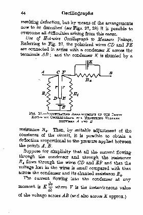
graph it is first necessary to make it polarized, so thatwhen the direction of the current reverses, the directionof the deflection is also changed. The method of
doing this is shown in Fig. 26, where two fine wiresCD and EF are connected in such a way that a con-stant direct current from the battery B can flowthrough them in parallel as shown by the arrows b b.
This current heats both wires equally and if the latterbe pulled bdck by equal tensions at their middle pointthe mirror m placed across the wires will not deflect.
If, however, a current from an external source be
Types of Oscillographs 43
sent through the wires in series as shown by the arrowsa a, then this current will oppose the current in the
left-hand wire and increase the current in the right-bandR
wire. If the resistance of each wire be r then--
C f
of the current flows through each wire. The rate at
which heat is given to the
left-hand wire is equal to
the product of the square of
the current multiplied by the
resistance = ( a -6 r.
Similarly, the rate at whichheat is given to the right-handwire is FIG. 26. ILLUSTRATING
METHOD OP POLABIZINGIK TTEH IHWTN HOT-WHUS
OSOTLLOGBAPH
The difference between these two rates is equal to
and this expression shows that the difference betweenthe rates of heating is proportional to the externalcurrent a, for all the other terms are constant. Thedifference will be positive or negative according to thedirection of current and the direction of deflection of
the mirror will therefore change for a change in thedirection of the current.
As, however, the wires have a definite amount of
thermal capacity they do not reverse their tempera-ture difference immeoliately the current reverses, andthis introduces a time lag between the current and the
44 Oscillographs
resulting deflection, but by means of the arrangementsnow to be described (see Figs. 27, 28) it is possible toovercome all difficulties arising from this cause.
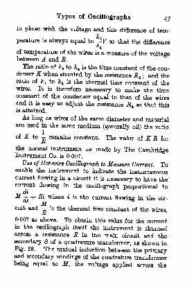
Use of Hotwire. Oscillograph to Measure Voltage.
Referring to Kg. 27, the polarized wires CD and FEare connected in series with a condenser K across theterminals AB
; and the condenser K is shunted by a
FIG. 27. ILLUSTRATING ARRANGEMENT OF THE IBWINHOT-WIBE OSOTLLOGBAPH FOB, MEASURING VOLTAGE
BETWEEN A AND B
resistance J24 . Then, by suitable adjustment of theconstants of the circuit, it is possible to obtain adeflection proportional to the pressure applied betweenthe points A, B.
Suppose for simplicity that all the current flowingthrough the condenser and through the resistance
-84 flows through the wires CD and JSF and that the
voltage lost in the wires is small compared with thatacross the condenser and its shunted resistance R^.The current flowing into the condenser at any
dvmoment is K where 7 is the instantaneous value
at
of the voltage across AB (and also across K approx.)

Types of Oscillographs 45
The current flowing through the resistance _R 4 is
V; therefore the total current through the wires is
Z- + -?dt^Ei
The difference between the rates of heating of the
72two wires is, as shown above. + 4o6r-
-Bi rTO
and this equals 4 dbr very nearly when the term-EI
is nearly unity. Substituting for a, the:
difference
between the rates of heating of the wires is given by
r
When a wire receives heat at a steady rate then its
temperature is raised until the loss of heat justbalances the gain, but, until this happens, the heat is
used up in two ways : part is stored at a rate propor-dT1
tional to - m H, ;and the rest is wasted by
radiation and is equal to E T 1 ;where 2\ is the tem-
perature m the mass, Ht the specific heat in joules,and E the emissivity of the wire in joules per sec.
dTThus, -^mHa + ET1 is the rate at which the
. dTenergy is received by one wire ; and
' m Ha + E T tCut
is the rate at which the energy is received by thesecond wire. The difference between these two rates
is the difference between the rates at which the wiresreceive electrical energy from the current a.

46 Oscillographs
Therefore,
(dt
'
1
which may be written for simplicity
Je /Pi-^a) , ,(T _ T _ , dv
k kSuppose we make ~ = -^
then, since the equation
holds under all conditions, it will now hold both whendv
, ^^ dvis large and when it is zero. When is zero
_ Jfc 4dt
1~J^
=^~^ C
1)
and, when is very large, so that the terms kV and
&B (^i - ^j) are negligible
i- dv1
dt~
k^dt
~kt dt
' ' '
From eqns. (1) and (2) respectively it will be seenthat the current flowing through the shunt resistance
RI is sufficient to maintain the wires at a difference
kof temperature equal to r^F; and, if the voltageT_
2 dvchanges for any reason at any rate 3-, the current
dt
flowing into the condenser is able to change the differ-
ence of temperature at a rated^ " T^ = ^.
dt kz dt
This means that the temperature changes are exactly
Types of Oscillographs 47
in phase with, the voltage and this difference of tem-&
perature is always equal to ^F so that the differenceA
2
of temperature of the wires is a measure of the voltagebetween A and B.
The ratio of k a to & 4 is the time constant of the con-denser K when shunted by the resistance R^ ; and theratio of Ic l to Jc a is the thermal time constant of thewires. It is therefore necessary to make the timeconstant of the condenser equal to that of the wiresand it is easy to adjust the resistance jR 4 so that thisis attained.
As long as wires of the same diameter and materialare used in the same medium (generally oil) the ratio
of JT to remains constant. The value of KR for
the normal instrument as made by The CambridgeInstrument Co. is 0-007.
Use of Hot-ivire Oscillograph to Measure Current. Toenable the instrument to indicate the instantaneouscurrent flowing in a circuit it is necessary to have thecurrent flowing in the oscillograph proportional to
^.diM -\- R% where * is the current flowing in the oir-
r1 Mcuit and is the thermal tinje constant of the wires,
JK '
0-007 as above. To obtain this value for the currentin the oscillograph itself the instrument is shuntedacross a resistance R in the main circuit and the
secondary S of a quadrature transformer, as shown in
Fig. 28. The mutual induction between the primaryand secondary windings of the quadrature transformer
being equal to M, the voltage applied across the
48 Oscillographs
oscillograph is iJR + M \ and, as long as E and Mdt
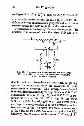
are properly ohosen so that the ratio M/B = 0-007, thedeflection of the oscillograph is proportional to the maincurrent within the definite limits of the instrument.
Constructional features of Hot-wire Oscillograph. Inpractice it is arranged that the wires CD and F E
VWWVTO'ff^n Lrsinr-\M
FIG. 28. ILLUSTBA.TIN-O ABBANGBOEBINT off THE IB-WINHOT--WIBH OSOELLOQBAPH BOB MEASITRING OUBBBNT
t IN THE MAIN
double back on themselves so that each is pullingagainst the other and only the difference in theirmovements is observed. The arrangement adoptedis shown diagrammatioally in Fig. 29 where C D C' D'corresponds to C D in Pig. 28, and E F E' F' corre-
sponds to E F in Fig. 28. If, in Fig. 29, the wiresCD and E F be looped together at their centre pointand kept in steady tension than any difference in the
temperature of the two wires will cause a movementof the wires at the centre towards the right or the left.
Similarly, the extension of the wires C' D' and E' F'

Types of Oscillographs 49
shown dotted will also produce a movement at their
centre due to the same difference in temperature butin an opposite sense, i.e. when the wires nearer the
observer move to the right those behind will move to
the left. This double movement will cause the small
mirror M to deflect and give anindication of the movement.
Sometimes the current is arrangedto flow only in the back wires CDandW F', corresponding to C D andE F in Fig. 28. This is the arrange-ment used, where the instrument is
immersed in oil and where the heated
oil rising from the front wires across
the mirrorM would cause a blurringof the spot.
In cases where oil is not used for
damping the movement but only for
cooling the wires the system shownin Fig. 29 does not carry any current
and is not immersed, but is used for magnifying the
movement of the current carrying wires as shown in
Fig. 30. In this case although the hot-wires CG^D^Dand EE-^F-^F are extended above the oil and there
tied together and provided with a mirror as shown, the
portions of the wires out of the oil do not carry anycurrent, as there are cross wires between C^ and D x
and also between F-^ and E;
see also Fig. 31. Withthis arrangement, as the movement is not dampedmechanically, there must be some electrical method of
damping it, or else controlling the blow given to the
wires when the voltage (or current), changes very
quickly. To accomplish this, an extra resistance is.
FIG. 29. ILLUS-TaiTiNG METHOD
OB- TYINGTOGBTHHB THJU
WIRES OF ANIBWIN HOT-WTBHOSOILLOGBAPH
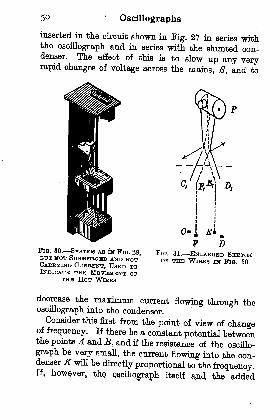
5 Oscillographs
inserted in the circuit shown in Kg. 27 in series withthe oscillograph and in series with the shunted con-denser. The effect of this is to slow up any veryrapid changes of voltage across the mains, S, and to
FIG. 30. SYSTEM AS is FIG. 29,BUT NOT SUBMHBGED AND NOTCABRYTNQ OUBBBNT, USED TOINDICATE THE MOVEMENT op
THE HOT WIBES
i
F DFIG. 31. ENLABGBD SKHTOHOF THE WIRES IN FIG. 30
decrease the maximum current flowing through theoscillograph into the condenser.
Consider this first from the point of view of changeof frequency. If there be a constant potential betweenthe points A and B, and if the resistance of the oscillo-
graph be very small, the current flowing into .the con-denser K will be directly proportional to the frequency.If, however, the
oscillograph itself and the axided

Types of Oscillographs 51
resistance be in series with the condenser the currentis no longer proportional to the frequency but, as the
frequency is raised, the current tends to a finite valueequal to the voltage divided by the sum of the two resis-
tances, and the actual value is easily found by means ofvectors.
The ratio of the current so found to the currentthat would flow if there were no series resistance forthe condenser is a measure of the reduction of deflec-tion due to damping. There is, however, an increase ofdeflection (up to a limit) for an undamped instrumentowing to the control force being opposed by the inertiaforces (see Fig. 4). The product of these two factors
gives the real magnification (or attenuation) for theparticular damping used.
In the arrangement (Fig. 28) used when investigatingthe current flowing in a circuit, the ratio secondaryampere-turns to the primary ampere-turns on thequadrature transformer gives a measure of the dampingon the element, it can easily be increased by connectinga resistance in parallel with the secondary circuitand across the oscillograph itself that is, if theresistance of the oscillograph is not low enough to
produce sufficient damping.Abraham Rheograph. If a moving coil galvano-
meter were used as an oscillograph there would bevery serious errors introduced owing to the inertiaof the coil and the damping if this were appreci-able, but Abraham has succeeded in making theseeffects negligible by introducing new forces to balancethem.
On p. 5 it is shown that, for a simple wire placedin a magnetic field, there are only four possible forces
52 Oscillographs
and the sum of these at every instant is equal to zero
thus
iB - k A -
/>v - am =
'
d A , d* Abut v = =- = and a =
dt dt
Therefore JB-Jc A - p =-r- m =10 dt
pdt*
It is obvious that it is only when -3- and -T-r- aredt dt z
iB 10negligible that = k A and t = A k.
10 -D
In order that i may always be equal to A k wejD
have to send two auxiliary currents through the wire;
di pthe value of the first of these is - and the value of
,. d*im **the second is -z -
The current through the wire would then be
. di p d*i ml +
dik+
di* ~k
iBbut since is a force on the wire it can be expressed
in terms of the control force by k Aj where A x is theTO
deflection required to give a force under steady
conditions. Then the total current
di dH m
Types of Oscillographs 53
will produce an electro-magnetic force
k dt~
Ic dt z
m
but this force plusf -k A- p-^ ml =( <ft dtf
a
j
since the sum of the electro-magnetic and mechanical
R
IQOOQ.
T MP Q.
FIG. 32. ILLUSTBAUNG ONE MBTHOD op CojuLrjiumFOB INHBTIA AND DAMPING IN THE ABRAHAM
RHBOGBAPH
forces must be zero, therefore Aj must always be equal
to A and = k A; that is, no matter what the
current is at any moment, or how rapidly it is changing,the deflection will be proportibnal to it as long as weare able to arrange that the current through the
(79, n /^2c /wi
rheograph is equal to 4- -- 4- _:
dt k^
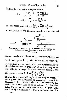
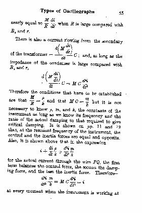
dt* kIn Pig. 32 one way (although not the original arrange-ment given by Abraham) of arranging a circuit to
accomplish this is shown, where i- is the current in themain circuit that has to be examined. In this dia-
gram PQ is, say, a wire stretched in a magnetic fieldand having a resistance r
;Q is a condenser and R a
6 (6887)
54 Oscillographs
resistance in parallel with it; and T is a transformer
which must fulfil the condition that the flux is propor-tional at every instant to the primary current, so thatthe voltage induced on the secondary winding is equal
to M~dt
Where M " the mutual induction between the
windings. ,
To fulfil this condition the current in the secondarymust be so small that the ampere-turns on thesecondary winding are small compared with those onthe
primary ; and either there must be no iron in themagnetic circuit or, if there is, there must be a largeair gap in the path. A practical value for the secondaryampere-turns would be about^ the primary ampere-turns at the highest frequency it was desired to record,say, 1000 per sec. corresponding to the 20th harmonicin a wave of 50 frequency. If great accuracy wererequired the ratio of secondary to primary ampere-turns would have to be made still smaller.
If a steady current i flow in the main circuit, partof this current will flow through the wire PQ and partthrough the secondary of the transformer and theresistance R.
The current in the wire is'
i and this can+ " + rbe made practically equal to i.
There is a voltage induced on the secondary of the
transformer equal to M~ and a current flows from
this winding through R and the wire PQ. The value
of this current is Mjjj/
(R + R t + r) ^ fc very
Types of Oscillographs 55
nearly equal to - J, when R is large compared with
.R, and r.
There is also a current flowing from the secondary
of the transformer = V
^*/ C
; and, as long as the
impedance of the condenser is large compared withMt and rt
J I -If w*
CL I Mj \S - JU_ \Jat fa*
Therefore the conditions that have to be established
are that - = and that M C = but it is not
necessary to know p, m, and k, the constants of theinstrument as long as we know its frequency and theratio of the actual damping to that required to givecritical damping. It is shown on pp. 11 and 12that, at the resonant frequency of the instrument, thecontrol and the inertia forces are equal and oppositeAlso, it is shown above that in the expression
m
for the actual current through the wire PQ, the firstterm balances the control force, the second the damp-ing force, and the last the inertia force. Therefore
at every moment when the instrument ia working at

56 Oscillographs
its own resonant frequency ; or, writing R. M. 3.values
a>*M GA = A
where A is the current in the main circuit then
MC =2
If an instrument be critically damped then, at its
own resonant frequency, the force due to the dampingis twice the control force. Suppose the actual damping
in an instrument is -th of that required to give critical
damping, then the maximum force due to damping2
is -th of k, the maximum control force, and the current
2required to give this force is -th of the current A in
2 A nthe mains. Thus, = current from the secondary
through the resistance R\ but this secondary current
co M A CD M A
, 2A coMA M 2Therefore - =- and = _
n R R can
To work out an example of applying the above
reasoning to a concrete case, take the Einthovenstring galvanometer mentioned on p. 26 where thesilver fibre is 0-02 mm. diameter, has a resistance ofabout 6 ohms, a natural frequency of 100 per sec., anda damping (say) ^th of critical damping.
If If be made small, C has to be large and E small,
Types of Oscillographs 57
so it is a matter of compromise what value to make M.
Suppose M be taken as 0-1 henry, then
M 0=co
a
r, 10=i= *6 '2 x 10
~6 farads>
con 0-1 x 6280 = 3142 2
An Einthoven galvanometer made into anrheograph by the mutual induction and the condenserwould retain its current sensitivity at att frequenciesand would be without distortion if E8 and r were madesmatt compared with the impedance of the condenser.
In the present case the impedance of the condenserat 1000 frequency would be about 6 ohms and, ifthe resistance Ra were, say 6 ohms also, the current
flowing into the condenser would only be6
A/6a + 12 2
of what it ought to be to give no change of sensitivityand no distortion that is, the higher harmonics offrequency about 1000 would be 45 per cent of theirtrue value.
In practice, care has to be taken that the resonancepoint in the instrument does not come into the work-ing range for, although there should be no error intro-duced at the resonance point if the adjustments bemade correctly, yet at that point we have two currentsof large values which are equal and opposite and twoforces which are equal and opposite, hence any varia-tion of the natural frequency of the instrument wouldupset the balance point and give a deflection muchgreater than the true value.
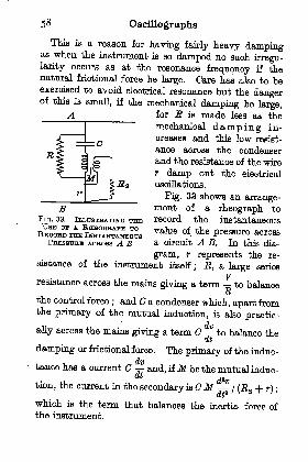
58 Oscillographs
This is a reason for having fairly heavy dampingas when the instrument is so damped no such irregu-larity occurs as at the resonance frequency if thenatural frictional force be large. Care has also to beexercised to avoid electrical resonance but the dangerof this is small, if the mechanical damping be large,
for E is made less as the
mechanical damping in-
creases and thiq Low resist-
ance across the condenserand the resistance of the wire
r damp out the electrical
oscillations.
Fig. 33 shows an arrange-ment of a rheograph to
record the instantaneous
value of the pressure across
a circuit A B. In this dia-
gram, r represents the re-sistance of the instrument itself
; E, a large series
Vresistance across the mains giving a term to balance
the control force; and a condenser which, apart from
the primary of the mutual induction, is also practic-
ally across the mains giving a term C to balance thedt
damping or frictional force. The primary of the induc-
tance has a current C and, ifM be the mutual indue -
j.
tion, the current in the secondary is CM/ (.R a -|- r) ;
dt
which is the term that balances the inertia force ofthe instrument.
FIG. 33. ILLUSTBATEN-Q THEUSH or A. RHHOQHAPH TORHOOBD THE INSTANTANEOUS
PBESSTTRH AOROSB A B

Types of Oscillographs 59
As the inertia forces can be so easily balancedAbraham has made rheographs carry mirrors of26 sq. mm. area or, say, 80 times the area of those onthe Duddell high frequency oscillograph ; and, in thefirst instance, the method was applied to a movingcoil galvanometer which shows its possibilities.
Nevertheless, every increase in the inertia forcemeans corresponding increase in the size of the con-denser and the mutual inductance and a correspondingreduction of the sensitivity, and is therefore to bedeprecated.
Electrostatic Oscillographs. Oscillographs, in whichthe deflecting force is the pull of an electrostatic field,have been used (unpolarized) by Professor Gray, andpolarized by Einthoven, by the author, and by Drs.Ho and Kato of Tokio University.Some of the difficulties and successes encountered
during a research extending (although not continuous)over some seven years are summarized below, partlyto show the convenience of the instrument for somespecial problems, and partly to show the difficulties tobe encountered and avoided.
s
All the mechanical problems present in the electro-
magnetic oscillograph are also present in the electro-static instrument, and it is necessary to have themechanical frequency high and the damping large if
the instrument is to indicate correctly.As, however, the maximum electrostatic force
present in air before breakdown occurs is small, it is
generally necessary to immerse the moving parts inoil for three reasons : (1) To get a greater electro-motive force between the plates, owing to the greaterdielectric strength of oil as compared with air
; (2) To
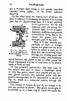
6o Oscillographs
get a stronger field owing to the specific inductive
capacity being higher; (3) To obtain sufficient
damping.On the other hand, the introduction of oil into the
field, in addition to increasing the inertia of the movingpart, has the disadvantage that, if it is not perfectly
homogeneous, the oil will
separate under the strong elec-
trostatic field, the oil of higherdielectric coefficient and greater
conductivity being drawn be-
tween the plates into the
strongest part of the field.
This field also attracts anyparticles of dust or foreignmatter and great care has to betaken to select a pure oil, tofilter into the containing vessel
through dry blotting paper andto keep it clean. Any accidental
spark between the plates in the oil often upsets thewhole experiment, and the oil may have to be filtered
again or fresh oil used.
Of the polarized instruments, the type used bythe author was that in which a diaphragm madeof very fine gauze, about (90)
a meshes per sq. cm.,was placed between two inductor plates and thegeneral arrangement of the instrument is shown inFig. 34, which is a horizontal section through theinstrument.
Two blocks of ebonite Bl and a are turned to fit
into one another as shown. The gauze diaphragm Dis soldered on to a brass ring It, which fits inside the
FIG. 34. SECTIONALPLAN op 'i*n u IBWIN
ELBOTROSTAHO OSOILLO-QBAPH
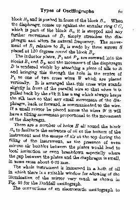
Types of Oscillographs 61
block a and is pushed in front of the block B^ Whenthe diaphragm comes up against the annular ring C C,which is part of the block 3 ,
it is stopped and anyfurther movement of B simply stretches the dia-
phragm and alters its natural frequency. The move-ment of BI relative to B z is made by three screws Splaced at 120 degrees round the block B^.The inductor plates, P and P a , are screwed into the
blocks B 1 and J3 a , and the movement of the diaphragmD is rendered visible by attaching a piece of silk to itand bringing this through the hole in the centre ofP! to one of two cross wires W which are placedvertically. It is arranged that .this cross wire standsslightly in front of the parallel wire so that when it is
pulled back by the silk it has a sag which always keepsthe silk taut so that any small movement of the dia-
phragm, back or forward, is communicated to the wire.If a small mirror be placed across the wires W it willhave a tilting movement proportional to the movementof the diaphragm.There are a number of holes H all round the block
-S a to facilitate the entrance of oil at the bottom of theinstrument and the escape of air at the top during thefilling of the instrument, as the presence of evenminute air bubbles between the plates would lead tolocal ionizatioh or even breakdown especially wherethe gap between the plates and the diaphragm is small,in some oases about 0-26 mm,The whole instrument is immersed in a bath of oil
in which there is a suitable window for allowing of theillumination of the mirror very much as shown inPig. 20 for the Duddell oscillograph.The connections of an electrostatic oscillograph to

62 Oscillographs
indicate pressure are shown in Kg. 35, where a batteryof total voltage 2 P is shown connected across the twoplates of the oscillograph and the source of voltage Fto be observed is connected between the middle pointof the battery and the diaphragm.The voltage between the upper plate and the dia-
phragm is P + F if the instantaneous voltage givenby the source be as
shown. The pull onthe diaphragm is pro-
portional to the squareof the applied voltage,and is, therefore, equalto KI (P -f F)
a. Simi-
larly, the voltage be-
tween the lower plateand the diaphragm is
(P - F) and the pull onthe diaphragm is K z (P - F)
B. Now K^ and K t can be
made equal by adjusting the distance of the plates, andthe resultant pull on the diaphragm is then equal to
K\(P + v}*-(P-v}*} = KPV and, as K and Pare both constant, the deflection of the diaphragm (andof the mirror) is proportional to F, the instantaneous
voltage applied, and will reverse when the voltagereverses. This assumes, however, that the natural fre-
quency of the diaphragm and of the wires is sufficientlyhigh to enable them to follow the voltage changes, andthat the diaphragm and wires are sufficiently well
damped to prevent them having appreciable free vibra-tions of their own. A frequency (in oil) of about 1500per sec. is attainable.
The essential calculations for a moving diaphragm
-JP
3Tia. 35. CONNECTION DIAQBAMPOB AN EitEOTBOSTATIO OSOXLLO-
G-BAPH USED TO INDICATEPBHSSUBH
Types of Oscillographs 63
are comparatively simple as long as the diaphragm is
assumed to be moving everywhere with simple har-monio motion and as long as every part of the
diaphragm moves in the same phase, an assumptionprobahly true for a light tightly stretched diaphragm.
If the required movement of the spot of light onthe screen or photographic plate is 2 cm., and if the
magnification is 6600 say, then the movement of
the diaphragm is or 3 X 10'4 cm.6600
If the resonant frequency of the instrument be 1500in oil and 2300 per sec. say, in air then, when the
diaphragm is vibrating at its own frequency over adistance 3 x 10~4 cm. on each side of the mean posi-tion, the restoring force must be always equal to theinertia force if there is no damping present.
The maximum inertia force = coz A m
; where Ais 3 x 10' 4 cm., and m is the mass of the diaphragmin grm. per sq. cm. As the wires in the gauze in thepresent case are 0-0034 cm. diameter, m is 0-016 grm ;
and the restoring force per unit area at the centre ofthe diaphragm is
co2Am = (2rr2300)
a x 3 X 10-4 x 0-015= 940 dynes.
It is immaterial to what this restoring force is duewhether to tension in the wires or stiffness
; theessential is that it must have this value for the givendisplacement.Now if the displacement under an electrostatic
pressure is to have the same value stated, the force
produced by the electrostatic field must be equal to940 dynes per sq. cm.
64 Oscillographs
The electrostatic pull between two parallel plates is
equal to
where 7 = difference of potential in electrostaticunits
; k = the specific inductive capacity of thedielectric = 2, say ; and t = the distance apart ofthe plates = 0-025 cm. in the case considered
Therefore - 94 x * (- 25)8
2V = 2-7 electrostatic units or 2-7 x 300 Yolts= 810 Volts.
In the above examples it is assumed that there is
only a pull on one side of the diaphragm and, toachieve this, it is desirable that the value of P, which ishalf the voltage of the polarizing battery, should beroughly equal to the maximum voltage from thesource to be investigated : that is that (P - F) shouldbe email compared with (P + F).The reason for the use of a gauze diaphragm, instead
of a thin sheet metal diaphragm, is that if the oil werenot permitted to move through the diaphragm itwould be impossible to get rapid movements owing tothe mass of oil that would have to be put in motion.The example is worked out above for a "
gap"
of0-025 cm. This is about the smallest practical andgenerally a gap of 0-5 cm. is better when, with apolarizing voltage P = 2000, a sensitivity of about2 cm. for a voltage of 1300 maximum, or, say, analternating sinusoidal pressure of 900 V (R.M.8.),would give a total swing of 4 cm.Binthoven Electrometer or Electrostatic Oscillo-
graph. To find the force on electrostatic oscillographs
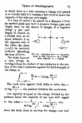
Types of Oscillographs 65
in which there is a wire carrying a charge and placedin an electric field it is necessary first of all to know the
capacity of the wire per unit length.If a wire of radius r be placed at a distance d from
an earthed plate and have a positive charge q per unit
length, then, by the theory of images, if a negativecharge q per unit
,
length be placed on,
a similar wire at an '
equal distance d on '
^
the opposite side of
the plate, the platecould be removedwithout disturbingthe lines of force ^IQ - 38. iLLTTSTaATTwa TEE CALOITLA-
The work done onTION F " CAPACITY J A WlBH
J..UO WU-lJi. U.UUO OUL WITH. BHQABD TO A PLATEa unit charge in
moving it from the surface of one conductor to the sur-
face of the other conductor against the field strength ofone charge, is
/ xJa=. (2d-r)
The work done against both fields is twice this =2d-r
4q log. = the pressure between the conductors.
The capacity is equal to the charge divided by the
pressure hence the capacity of one wire with regard
to the other *-f_ L__ but
,
since the work done in moving the charge over half
66 Oscillographs
the distance, i.e. from the position of the plate up tothe charged conductor, is only JV, the capacity ofthe original conductor with regard to the plate is
twice the capacity from wire to wire and is equal to1
712 log.
Since r is small compared with d the expression for the
capacity of the wire with regard to the plate may be
taken to be
If the wire be placed midway between two parallelplates the capacity of the wire with regard to the two
plates is twice the above or-- but 2d is the dis-i
*dlog, 7
tanoe of the plates apart = D, so that the capacity ofa wire of radius r, midway between two parallel
plates which are a distance D apart, is _-_ If
the wire be immersed in oil of specific inductiveTc
capacity k the capacity =- electrostatic units.
Now the force on the wire per unit length will beequal to the field strength times the charge per unitlong-th divided by the specific inductive capacity.The field strength E is equal to the pressure V^
between the two plates times the specific inductive

Types of Oscillographs 67
capacity divided by the distance Z> between theplates or E = V-Jc/D
Therefore the force on the wire per unit length =VJ& jfc 7,
"r
where 7a is the pressure of the wire above the meanof the pressures of the two plates. This expressionreduces to
F F Jfc
.Force on wire, per unit length = -dynes,
DloSe-T
where V1 and F a are measured in electrostatic units.Now the maximum force permissible depends on the
maximum charge we can safely give to the wire andthe maximum field we can allow between the plates.The maximum stress due to the charge on the wire
ifl at the surface of the wire, and for a voltage F a is
equal to, D
r log.-
Since this stress is superimposed on that due to themain field the maximum stress due to the charge onthe wire can be taken as half the allowable stress in themedium. For oil a working stress of 3000 V per milli-metre is allowable
; hence the permissible stress dueto the charge on the wire is 1600 V per mm., or 50electrostatic volts per cm. Therefore
27a* = 50D
68 Oscillographs
To apply this to a specific example, let us take the
case corresponding to that worked out for a silver
wire 0-002 cm. diameter carrying a current in a mag-netic field, (p. 25) and suppose that in the present case
the wire is carrying a charge in the electrostatic field
due to two parallel plates 1 mm. apart.Then D = 0-1 cm. and r = 0-001 cm.
; and, fromthese values, the maximum value of F a
= 0-5 electro-
static units approximately (or 150 V). If the maxi-mum stress due to the voltage between the parallel
plates be also 50 electrostatic volts per cm.Fa maximum = 5 electrostatic units (or 1600 V) and
the maximum force per unit length
5x0-5x2
which would be equal to the force developed by acurrent of 0-01 A flowing in a wire placed in a field
of 11,000 lines per sq. cm.
Such a wire we found (on p. 26) required a force of
about 1 x 10-B x 20,000 dynes to give a deflection of1 mm. when used with a microscope of magnification600
; so that an effective force of 0-2 dyne gave adeflection of 1 mm. If, therefore, in the present case,the wire were again placed under such tension thatits frequency was 100 per sec. the deflection for a
polarizing voltage of 1600 (max) or P = 750 V and160 V on the wire would be 55 mm.As ionization does not generally take place, even
with the wire in air, at less than 300 V, F2 may beincreased to 300 when the value given by the abovereasoning is below 300. In the present instance, withF, = 300, the deflection would be 110mm. If the

Types of Oscillographs 69
least workable deflection be 20 mm., tlie frequency of
the wire can be increased to 100 V&5 or 230 per sec. ;
but how much higher the deflection can be pushed orthe frequency increased depends on how near oneworks to the breakdown point.An electrostatic oscillograph with a single wire
placed between two parallel plates is used very muchas shown in Fig. 35 except that the diaphragmD (shownin cross section in Fig. 35) is replaced by a single wire.The recording apparatus as shown in Fig. 14 is used.As the sensitivity does not vary with the length ofthe wire, so long as the frequency is constant, it is
advisable in the electrostatic instrument especiallyfor the higher frequencies to make the length of thewire short, for this adds to the stability of the fibre.As the beam of light passes at right angles to thefield there is no inactive part of the field as in the
corresponding electromagnetic instrument.Ho and Kato Electrostatic Oscillograph. This
instrument has a pair of wires placed in an electro-static field and so arranged that when the potentialof the one increases above zero the potential of theother falls below zero by an equal amount. Thearrangement is shown diagrammatioally in Fig. 37which is a horizontal section through the instrument.P! and P a are the two field plates ; two wires W^ andWt , shown in section; are placed close together andcarry a mirror M which is illuminated by a beam oflight through the opening 0. The wires are insulatedfrom each other and from the mirror.The force on each wire can be calculated from the.
equations given for the Einthoven instrument, and fortwo wires
sufficiently close together the magnification8
(5307)
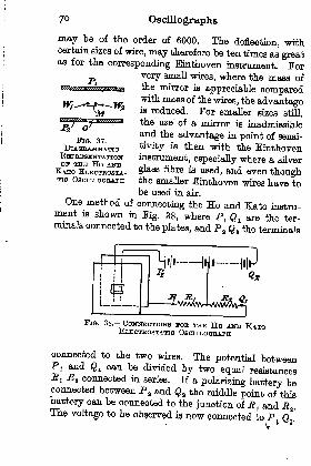
7 Oscillographs
may be of the order of 6000. The deflection, withcertain sizes of wire, may therefore be ten times as greatas for the corresponding Einthoven instrument. For
very small wires, where the mass of
wtiutuwftttiBBta tte mirror is appreciable comparedwith mass of the wires, the advantageis reduced. For smaller sizes still,
the use' of a mirror is inadmissibleand the advantage in point of sensi-
tivity is then with the Einthoveninstrument, especially where a. silver
glass fibre ia used, and even thoughthe smaller Einthoven wires have tobe used in air.
One method of connecting the Ho and Kato instru-ment is shown in Fig. 38, where P x Q L are the ter-minals connected to the plates, and P a Q t the terminals
FIG. 37.
DlAGBAMMATIORHPBBJSHNTATIONOB1 THH HO AND
KATO ELBOTBOSTA-TTO OSCILLOGRAPH
FIG. 38. CONNECTIONS FOB THH Ho AND KATOELBJOTBOSTATIO OBOTLLOGBAPH
connected to the two wires. The potential betweenPI and g x can be divided by two equal resistancesRI .flj, connected in series. If a polarizing battery beconnected between P B and fl
the middle point of thisbattery can be connected to the junction of R l and R a .
The voltage to be observed is AOW connected to P; Q .
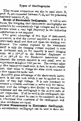
Types of Oscillographs 7T
Tlie reverse connections can also be used where E 1and Jt a are connected between P a Q t and the polarizingbattery between P^ Q .
Scope ol Electrostatic Oscillographs. It will be seenfrom the foregoing that electrostatic oscillographs areauitabJe for comparatively high voltages and for waveForms where a very high frequency in the indicatinginstrument is not required.Tlie great advantage of this type of instrument,
lowever, is that the current required to operate it is
extremely small and does not upset the working con-litions. The current required by the instrumenttself is only the charging current required to raisets potential and, as the capacity is small (rangingrom 40 x 10* /*F in the stretched diaphragm to"5 X 10-a //F for ^e Binthoven iofltru^nt con.
idered) the current required is very small, even atrequenoies as high aa 1000 per sec. The current takeny the instrument itself may, in fact, be much smallertian that taken to charge the wires which connect it3 th.e apparatus under test.
Another great advantage of the electrostatic instru-tent is the ease with which it can be applied to cir-lits of very high voltage. It is only necessary to)nnect a suitable condenser in series with the instru-.ent and the voltage is then divided up between the>ndexiser and the oscillograph in the inverse ratio ofteir capacities. If oil be used in the oscillograph, theme sort of oil must be used in the condenser, so that.e electrical time constants of the oscillograph andthe condenser are equal.Power Measurements by Electrostatic Oscillograph.i electrostatic oscillograph can be used to show the
AAAAAAA/
72 Oscillographs
instantaneous power given to a circuit. Fig. 39 showsthe well-known arrangement of an electrostatic watt-
meter to measure mean watts, but, if the instrumentbe of high enough frequency, it will show the instan-
taneous watts or the power being given to the circuit
A B no matter what the type of circuit may be. This
is exactly true if the mov-
ing wire (or diaphragm)be connected to the middle
point of the resistance Rlt
but the instrument mea-sures the power in the
circuit A B plus half the
power being wasted in jR B
if the moving wire be con-
nected to the point Bdirectly or through a con-
denser. A new use can befound for an electrostatic
oscillograph wattmeter tomeasure power at frequencies much higher than theinstrument can follow. Thus, in wireless telegraphy,such an instrument can show the amount of powergiven to the aerial at, say, 100,000 cycles per sec. whenthe aerial is excited by means of a "
spark"method.
Under such conditions, where the damping of theoscillations is small, the rate at which power is given tothe aerial can be shown by a curve which might havea shape as shown at Fig. 40(a). In this diagram, theheavy line gives the mean of the impulses due to therapidly varying power in the aerial which the instru-ment is unable to follow. If the damping be large, orthe frequency high, then the instrument will only have
FIQ. 39. ILLTJSTRATTNO THEPBnTGrPLB OB" THE
ELHOTBOSTATIO

Types of Oscillographs 73
a throw given to it as shown in Fig. 40(6). In thatcase the instrument will have to be calibrated as aballistic wattmeter by discharging a condenser through aresistance when the power given to the resistance is
known to be % KV 2if the circuit can be closed quickly
enough.In using electrostatic instruments where the mpmTian-
ioal damping is not sufficient it is desirable to use a series
(S)FIG. 40. ILLUSTBATINQ THE MEASUREMENT OF HIGH
FBEQUENOY POWEB,
resistance to give some electrical damping, especiallyas this constitutes a safeguard at the same time.As the instrument is a condenser the maximum
rate at which it can be charged is equal to V/fi,where R is the series resistance and V is the appliedvoltage across the resistance and oscillograph.
If Q be the charge that would eventually be storedin the oscillograph if the applied voltage remainedconstant, and if Q be the charge after a time t, then it
can be shown that
where C is the capacity of the oscillograph and E is theseries resistance.

74 Oscillographs
H Qo ~Q, the portion of the oharge which has still
to flow in, be expressed as a fraction, ^th of the finaln
charge, then
t = 2-3 CR Iog 10n sec.
When n= 10, i.e. when there is a tenth of thecharge still to flow in
t = 2-3 CR sec.
so that nine-tenths of the oharge and of the voltageof a condenser has been attained in a number ofseconds equal to 2-3 times the time constant.
Suppose, for example, that the oscillograph has acapacity 40 x 10- farads and R = 10 ohms
; then,
for - =n 10
'
t = 2-3 x 40 x 10'12 x 10= 0-92 x 10-* sec.
that is in a time equal to ^^ sec., the voltage willhave already attained 90 per cent of its final value,a*"1 m *z?ra seo. it will attain 99 per cent of its finalvalue.
It is obvious, therefore, that a megohm in serieswith the instrument will not produce appreciabledistortion of the curve, and even 5 megohms will pro-duce less distortion than normal oil damping.The resistance of 5 megohms is put in series for apressure of say, 1000 V, so the current that would passif the osculograph.broke down is only 1000/(6 X 10 fl
) Aor 200 M- This would also be the maximum currentthat would flow through the experimenter if heaccidentally touched the
oscillograph, provided that

Types of Oscillographs 75
the only incoming source of high potential was throughthe resistance of 6 megohms, and that this highresistance was able to stand up to the high voltageacross it.
If the same oscillograph were used on, say, 40,000 Vthe series condenser would be one-fortieth of 40 X 10"12
farad or 1 x 10~12; and the series resistance would be
200 megohms, whichwould again only allow
the same small current
as in the preceding case. =j= C'fxtf1*
farad.
A diagram of the con-
neotions for such anelectrostatic osoillo-
graph working on
40,000 V is given inTlSrr A "I Tn -nr>o /i^' A ^1Q - *1. CONNECTIONS FOB AN-Tig. 41. In practice a ELHOTBOSTATIO OSOUJXJGBAPHsmall portion, say one
' WOBKING ON 40,000 Von^rs
megohm, of the series
resistance is put in series with each side of the polarizingbattery, GO as to reduce the current from the batteryin case of a breakdown of the oil in the oscillographdue to some excess of applied pressure.
Figs. 4246 are reproduced from records taken bythe author during an investigation into the variationof wave on the secondary of a high tension testingtransformer of 4 KW output.
This transformer had a transformation ratio of
140 to 40,000 V and, owing to its comparatively smallsize and high voltage, resonance could take placebetween the leakage self-induction and the self-capacityof the secondary. When the alternator speed wasadjusted so that resonance took place corresponding to

FIG. 44. REOOBDS SHOWING THH POWEB SUPPLTHTDPHOII THE SECONDABY op A HIGH TENSION TBANS-
FOBMBB TO A WATHB LOAD(Note. The voltage curve IB reversed for clenrneHe)
Fro. 45. RECOBDS SHOWING POWBB SUPPLIED J-BOMTHE SBCONDABT OF ONE TBANSPOBMBB TO A BOMILABTBANSFOBMEB PLAOHD BACK TO BACK WITH nvoltage curve la reversed for oleameBa)

Types of Oscillographs 79
Figs. 44-46 are records illustrating the use of the
electrostatic oscillograph as a wattmeter. The curve
marked W represents the instantaneous power, andP is the pressure curve, and / is the current curve for
the primary. Fig. 44 is for the power supplied fromthe secondary of the high tension testing transformer
FIQ. 46. KBCORDS STMTT^AB TO THOSE IN FIG. 45, BUT WITHTHU AITEBNATOB USHD FOB FIGS. 42 and 43
(Nott. Voltage curve reversed and currant curve displaced for clearness)
mentioned above, to a water resistance, the primarycurrent and pressure being measured on a hot-wire
oscillograph. Fig. 46 is a record of the power givenby the secondary of the transformer to a similar
transformer placed back to back with it, the current
and pressure waves on the primary again beingmeasured by a hot-wire oscillograph. The records in
Fig. 48 were taken under conditions similar to those
for Fig. 45, except that the current wave was dis-
placed for the sake of clearness and the alternator was
80Oscillographs
the same as for Fig. 42. The wave W in Pig. 46 showsvery clearly the rapid surging of power between thetwo transformers as well as the slower flow of powerto supply the losses in the second transformerCathode Ray Oscillographs. The cathode ray oscillo-
graph involves principles which have not been discussedup to this point ;
a complete chapter has, therefore,been devoted to a description of its working and itsuses (see p. 126).
CHAPTER in
HKEOBS OF INDICATION METHODS OF DAMPING-A2JTD NEW METHODS OF CONNECTION
As an oscillograph cannot always be of sufficiently
high frequency, compared with the frequency of the
source being investigated, it is sometimes necessaryto correct the curves of the instrument where the
highest accuracy is required. The relation of the
control, damping, and inertia forces is shown in Fig.4 (p. 10) and the fact is there established that the
resultant of these sources must balance the force dueto the current in the instrument.
Magnification with and without Damping. If the
damping of the instrument be very slight correspondingto, say, an Einthoven oscillograph with a fairly heavywire (say, 0-02 mm. diameter), or to a Duddell oscillo-
graph without damping oil, then the only effective force
is the resultant of the control and the inertia forces.
The maximum inertia force for a simisoidally
varying deflection is CD*Am and, for a constant swing,is therefore proportional to the square of the frequency.At the resonance frequency, /H , of the oscillograph
the maximum inertia force is equal to the
control force, hence
At any frequency / at which the oscillograph is
operated
81
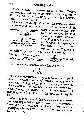
82Oscillographs
but the resultant internal force is the difference^01
This ia shown in Kg. 47 for unit deflection and wherethe vectors * and ^ or
to each other. Theresultant control for unitdeflection varies therefore
zero frequency to
WITH vnBY^ ""
C//A)a^ at frequency /.
DAMPING The deflection for unit cur-
inversely proportionalto
Deflection atfrequency/ ^
Beflection at zero frequency^^ -
(///E ) 25;=
This ratio is the magnification and equals
of, would be in&nty. In practioe it may be
is^P^ the vector. which
ftaQt meohaili^ ^ce for thef

Methods of Damping
If, taking the general case, the damping be n times
critical damping then, since p a at= 2K = 2o}*m, we
have : po> = np c ca= 2nK = 2na)*m at the resonant
O1 OZ~ 0\3 0* OS O6 0-7 O8 O9 1-0 1-f 1-2 J-3 J-4- 1-5
Ratio of actual to resonant frequency -$Jj
FIG. 48. CDBVBS SHOWINQ MAGNTFIOATION AS A FUNCTIONOP THH RATIO (WORKING FKHQUBNCY/RHSONANOI! FHB-
QDBNCY), POB DnmBBiNT VALTJUS OP DAMPING
frequency. Let the ratio of the frequency at which the
oscillograph is working to the resonant frequency
(=//) = *, than
and
p CD at frequency / = 2nEk
at frequency f = = Jc*K,
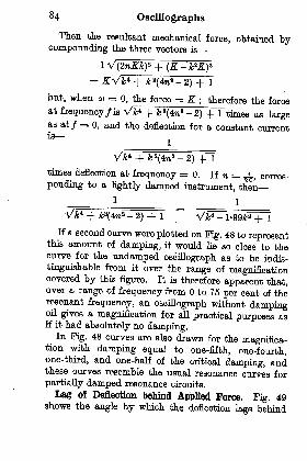
84 Oscillographs
Then the resultant mechanical force, obtained bycompounding the three vectors is
TT--2) -f 1
but, when co = 0, the force = K; therefore the force
at frequency/is Vk* + k 2(4?i
2 -2) + 1 times as large
as at / = 0, and the deflection for a constant currentis
times deflection at frequency =0. If n = ^, corres-
ponding to a lightly damped instrument, then
1
= 1
Vk* + k*(4:n*-
2) + 1
~ W- l-99*+lIf a second curve were plotted on Fig. 48 to represent
this amount of damping, it would he so close to thecurve for the undamped oscillograph as to be indis-
tinguishable from it over the range of magnificationcovered by this figure. It is therefore apparent that,over a range of frequency from to 75 per cent of theresonant frequency, an oscillograph without dampingoil gives a magnification for all practical purposes asif it had absolutely no damping.
In Fig. 48 curves are also drawn for the magnifica-tion with damping equal to one-fifth, one-fourth,one-third, and one-half of the critical damping, andthese curves resemble the usual resonance curves for
partially damped resonance circuits.
Lag of Deflection behind Applied Force. Fig. 49shows the angle by which the deflection lags behind
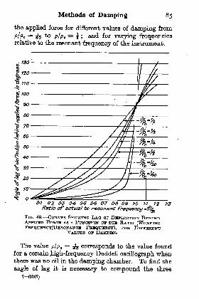
Methods of Damping 85
the applied force for different values of damping from
P/Po = *jy* P/Po
= i ; and for varying frequenciesrelative to the resonant frequency of the instrument.
O-J 0-2 03 (M- 0-5 &6 O7 0-8 Ch9 1-0 1-1
Ratio of actual to resonant frequency m1-2 1-3
FIG. 49. OUHVUS SHOWING LAO OP DHFLHOTION BEHINDAppT.rnm FOBOH AS A FuN-onoN OP THH RATIO (WOBKINGFaHQtrHNOY/RBSONANOH FBBQrTHNOY), FOB DrETHBirNT
VALTJBS OF DAMPING
The value pfp e= ^ corresponds to the value found
for a certain jiigh-frequenoy Duddell oscillograph whenthere was no oil in the damping chamber. To find the
angle of lag it is necessary to compound the three
7 (6897)
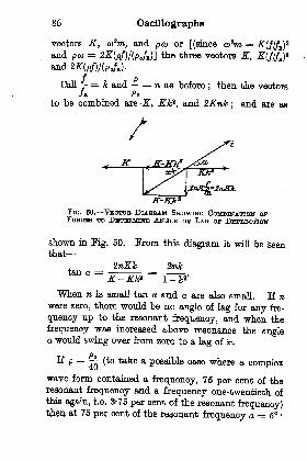
86 Oscillographs
vectors K, o>*m, and pco or [(since aPm =and pco
= 2E(Pf)/(Pefz)] the three vectors K, J(///E)
and 2E(Pf)/(Pofli).
Call = k and = n as before;then the vectors
/B PC
to he combined are E, Kid1,and 2Knk
; and are as
K
K-IO?FIG. 50. VHCTOB, DIAGRAM SHOWING COMBINATION OFFOBOBS TO DHTEBMrtra AlTQLH O! LAQ OP DHPLBOTION
shown in Fig. 60. From this diagram it will be seenthat
. 2nJctan a =
E-Ek* I-k*'
When n is small tan a and a are also small. If nwere zero, there would be no angle of lag for any fre-
quency up to the resonant frequency, and when the
frequency was increased above resonance the anglea would swing over from zero to a lag of 'IT.
E p =-^
(to take a possible case where a complex
wave form contained a frequency, 75 per cent of theresonant frequency and a frequency one-twentieth ofthis again, i.e. 3-75 per cent of the resonant frequency)then at 76 per cent of the resonant frequency a = 6

sto&pur 'ooje^fu/^nyop puiyeq uoiioo/jopJO$B-J
t>
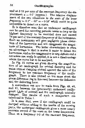
88Oscillographs
and at 3-75 per cent of the resonant frequency the dis-
placement a = 0-1 (approx.). The relative displace-ment of the two vibrations to the scale of the tower
frequency = 0-1 - -26 = - 0-15 which would be quiteimpossible to detect on a curve.
It is therefore seen that an undamped oscillographcan be used for recording periodic waves as long as theHighest frequency to be recorded does not exceed75 per cent of the resonant frequency of the instrument.Such an instrument will give negligible phase distor-tion of the harmonics and will exaggerate the magni-tude of harmonics. The latter characteristic is oftenan advantage in that it makes it easier to detect theharmonics, and as the exaggeration is very definite and, acorrection can easily be applied, it is not a disadvantagewhere the curve has to be analysed.
In Fig. 51 curves are given showing the magnifica-tion of an
oscillograph for critical damping and fortwice critical damping plotted against the ratio of thefrequency to the resonant frequency of the oscillo-
graph. There is also plotted on the same sheet thephase difference (lag in this case) between the deflectionand the
deflecting force.
A comparison can now be made from Figs. 48, 49,and 61, between the(practically) undamped oscillo-
graph (<feth of critical) and the oscillograph criticallydamped. The results of such a comparison aretabulated in Table I.
It is seen that, even if the oscillograph could bedamped without adding to the inertia of the movingparts, the undamped oscillograph gives a more nearlyaccurate record of the wave at the lower frequenciesThus, at a frequency 0-2 of the resonant frequency,
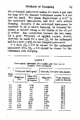
Methods of Damping 89
the undamped instrument makes the wave 4 per centtoo large and the damped instrument makes it 4 percent too small. The phase displacement is 0-57 inthe undamped instruments, and 22-5 with critical
damping. Actually, if the undamped instrument beimmersed in oil to secure damping, ite resonant fre-
quency is reduced owing to the inertia of the oil putin motion. Any comparison between the two cases,for a given frequency of applied current, should,therefore, be made for a ratio ///E for the undampedand for a ratio l-5///B for the damped instrument.
If a ratio ///a = 0-2 be chosen for the undamped,instrument then ///R = 0-3 should be chosen for theinstrument with damping.
TABLE I
COMPABISON BBTWHHN UNDAMPED ANDDAMPED
0-1
0-2
0-3
0-4
0-5
0-6
0-7
0-8
0-9
1-0
1-1
1-2
1-01
1-041-1
1-10
1-33
L-56
1-96
2-77
6-26
4-76
2-27
0-280-fi7
0-9
1-4
1-9
2-7
3-9
8-3513-6
90-0165172
0-990-960-920-850-8
0-7350-870-61
0-B650-5
0-4530-41
11-4
22-530-444-053-062-069-6
77-083-50-0
96-596-5
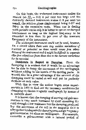
9o Oscillographs
On this basis, the undamped instrument makes the
record (at ///R = 0-2) 4 per cent too large and the
critically damped instrument mates it 8 per cent too
small, the relative phase displacement being 0-57 and
30-4 in the respective cases. When one is dealingtcith periodic waves only it is better to use an undampedinstrument as long as the highest frequency to be
recorded is less than 70 per cent of the resonant
frequency of the instrument.
The undamped instrument could not be used, 'however,
in a circuit where there were any sudden variations ofcurrent or potential as these would cause free vibra-
tions of the instrument and it might be difficult to separatethe free vibrations from those due to the current variationsto be recorded.
Desiderata in Regard to Damping. From the
foregoing it is evident that it would be an advantageto be able to damp the movement of the oscillographwithout adding to the inertia of the moving parts. It
would also be a great advantage if the amount of the
damping could be varied at will and yet be perfectlydefinite at each value.
With this in view the author began some experi-ments in 1907 to find out the necessary conditions for
damping an electro-magnetic oscillograph by means ofa suitable shunt.
It is known that the damping of moving coil galvano-meters is very much increased by short circuiting thecoil through a low resistance but the damping producedby the movement of the coil in the magnetic field is
altogether inadequate for damping even ahigh frequencygalvanometer, let alone an oscillograph. For example,consider a galvanometer with a natural period of
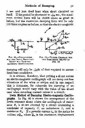
Methods of Damping
1 sec. and just dead beat when short circuited onitself. If the period be shortened to ^^ sec., the maxi-
mum control force will be 10,000 times as great as
before, but the TnairiTmTm damping force will be only100 times as great as before, so that the electro-magnetic
FIG. 62. CONNECTIONSFOB THE IBWIN RBSONANT
SHUNT FOB ELHOTBO-OSOTLLOQBAPHS
FIQ. 53. VHOTOB DIAGBAM FOBTHB CONDITIONS SHOWN IN
Fia. 62
damping will only be -^^ of that required to secure
dead-beat conditions.
It is evident, therefore, that putting a shunt across
an electro-magnetic oscillograph will not damp out free
vibrations of the wires or stripes and in one respectthin is fortunate, for otherwise the damping of an
oscillograph would vary with the value of the shunt
used when recording current values in a circuit.
Irwin Method of Damping Electro-magnetic Oscillo-
graphs. In Fig. 52 is shown the arrangement of the
Irwin resonant shunt where the oscillograph of resist-
ance RI is shown shunted by a circuit containing a
condenser of capacity C, an inductance L, and a
resistance .R 2 . If a periodic current im in the mains be
written a>Qm) where Qn is the maximum displacement
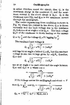
92 Oscillographs
in either direction round the circuit, then Q g is themaximum charge in the condenser C, and the maxi-mum current in the shunt circuit is Q t co. Q is themaximum quantity, and QO CO.JB the maximum current
through the oscillograph.The vector representing these conditions is shown in
Fig. 63, where the current in the shunt, Q t ca is drawnvertically and the back voltage due to the resistance-R a is shown at an angle IT with Q , co . The back voltageQa/C of the condenser is shown leading on the current
TT
Q s o) by - and the voltage Q t ct)*L lagging by ^.
The resultant back voltage is
and lags by an angle a behind Q a coB z ,but this resultant
voltage is also the voltage given by caQJi^ therefore,Q a> and
Q,
are at an angle TT to each other and the angle betweenQ co and Q,a> is a where cos a
If the voltage across the oscillograph and shunt =*= VV V
then Q = ~ and Q. =
Qm =
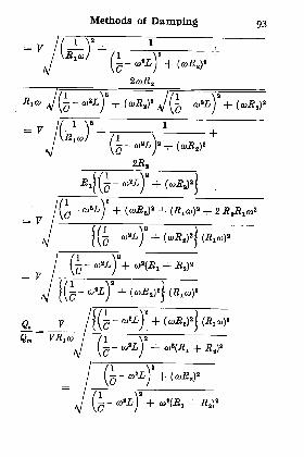
Methods of Damping 93
17 i;
F f i y i
UW +7I
~'M
= F/tf-y+Ti\R l(oJ /i
v \c
= F
ft. JQm
\c~coL
)+ ^(-BI +

94 Oscillographs
The ratio -^ is the reduction in the deflection that*vm
takes place due to the presence of the resonant shunt,
but the current coQ through the oscillograph produces
(as shown on p. 84) a magnification
1
times as great as it would produce at a frequency verynear zero. Therefore, the ratio of the deflection of the
Ct)
oscillograph with shunt at frequency -~-_ to the deflection
of oscillograph without shunt at a very low frequency
and this is the general expression for an oscillographso shunted and with a damping n times as great as
critical. Generally n is only a small fraction.
To change from the general case to the particular,where the resonant frequency of the electrical circuit
used as a shunt is equal to the resonant frequency of
the oscillograph, we have
a1 K
J== =
CD = a) k where o> is the resonant frequency.
co*L = co *k*L but o}*L = ^2
therefore co*L =
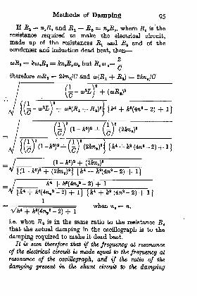
Methods of Damping 95
If RI = naRe and R^ + J2 B= n^R^ where R is the
resistanoe required to make the electrical circuit,made up of the resistances Rt and jRa and of thecondenser and induction dead beat, then
2coRi = kcDoRi = &7vR o but R e co
=
therefore cuJ? a= 2Jcnt/C and eo^ + .#) = 2knv/C
-JI (1
-jfe) + (2yfc7iv )
a} {
A4 + yfea(4?i
B -2) + 1
j
A;4 + A;
2(4TOt
a -2) + 1
=
, when n. = n.V fc
4 + fca(4V -
2) + 1
i.e. when R z is in the same ratio to the resistance Rthat the actual damping in the oscillograph is to the
damping required to make it dead beat.
It is seen therefore that if the frequency at resonance
of the, electrical circuit is made equal to the frequency at
resonance of the oscillograph, and if the ratio of the
damping present in the shunt circuit to the damping
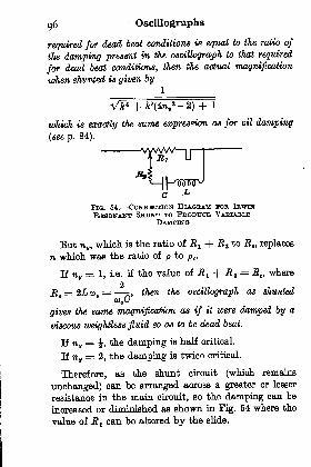
96 Oscillographs
required for dead beat conditions ia equal to the ratio of
the damping present in the oscillograph to that required
for dead beat conditions, then the actual magnification
when shunted is given by1
which is exactly the same expression as for oil damping
(see p. 84).
Fia. B4. CoirerHOTioN1 DIAGRAM FOB IEWIN
RESONANT SHTJNT TO PBODUOB VABIABLBDAMPING
But nv ,which is the ratio of R + JB a to .R
fl , replaces
7i which was the ratio of p to p e .
If TIV= 1, i.e. if the value of E + R t
= R,where
2J2 =2Lco =
,then the oscillograph as shunted
u
gives the same magnification as if it were damped by a
viscous weightless fluid so as to be dead beat.
If ?iv=
,the damping is half critical.
If nv= 2, the damping is twice critical.
Therefore, as the shunt circuit (which remains
unchanged) can be arranged across a greater or lesser
resistance in the main circuit, so the damping can be
increased or diminished as shown in Fig. 54 where the
value of R! can be altered by the slide.
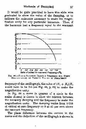
Methods of Damping 97
It would be quite practical to have this slide wire
graduated to show the value of the damping, or to
indicate the resistance necessary to make the magni-fication unity for any particular harmonic. Thus, if
the harmonic had a frequency equal to the resonant
0-2 0-4- 0tf O8 1-0 _ 1-2 1-4-
Ratio ofactual to resonant frequenq/m&&FIG. 58. CURVE SHOWING DAMPING REQUIBHD FOB UNITY
MAGNIFICATION, AT VABIOUS VAT/UBS OF FREQUENCY
frequency of the oscillograph, the value of (E^ + E^)jEwould have to be O5 (see Fig. 48, p. 83) to make the
magnification unity.In Fig. 55 a curve (a quarter of a circle to the
scales chosen) is drawn to show the relation betweenthe necessary damping and the frequency to make the
magnification unity. The damping varies from 0-705
of critical at zero frequency to at 41 per cent abovethe resonant frequency.The phase difference between the current in the
mains and the deflection of the oscillograph is shown in
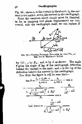
98 Oscillographs
Fig. 56; where i s is the current in the shunt ;
im the cur-
rent in the mains ;and i the current in the oscillograph.
Since the resonant shunt circuit must be identical,
as far as damping and phase displacement are con-
cerned, with the oscillograph itself, we can replace K
Fia. 66. VHOTOB, DIAGBAM RELATING TO THE TJsn or
IBWIN RESONANT SHTTNT
by 1/0 ; p by B t ;and m by L as shown. The angle
6 gives the angle of lag of the oscillograph deflection
behind the current in the main, and a is the lag of the
deflection behind the current in the oscillograph.
Now from the figure it will be seen that
i. r\- * giTi a *, ,
tan0 = -^-? = ^'
h tanacos a tn oos a
cos a
but cos a =
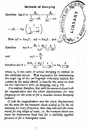
therefore tan 6 =
Methods of Damping
T*
therefore
and
Now <u(7 =
tan 6 =
therefore tan 6 = _~
where Tij,is the ratio of actual damping to critical in
the electrical circuit. This expression for determiningthe angle lag of the oscillograph deflection behind the
current in the main circuit is exactly the same as that
for the instrument with oil damping (see p. 86).
It is evident, therefore, that with the resonant shunt both
the magnification and the phase displacement for anyfrequency are the same as for a massless viscous dampingmedium.
If both the magnification and the phase displacementare the same for the resonant shunt method as for the oil
damping for every frequency, then they wiU give the same,
record for any shape of wave, i.e. the resonant shunt can
make, the instrument dead beat for a suddenly applied
pressure or for a rectangular wave.
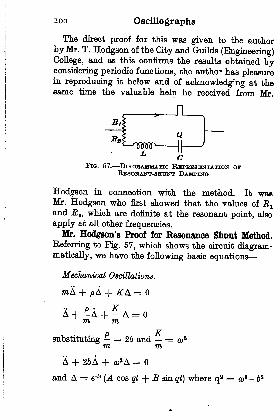
ioo Oscillographs
The direct proof for this was given to the author
by Mr. T. Hodgson of the City and Guilds (Engineering)College, and as this oonfirms the results obtained byconsidering periodic functions, the author has pleasurein reproducing it below and of acknowledging at thesame time the valuable help he received from Mr.
CFIQ. 67. DIAGRAMMATIC RBPBHSENTATION ov
RnSONANT-HHUNT
Hodgson in connection with the method. It wasMr. Hodgson who first showed that the values of ^ a
and RI, which are definite at the resonant point, also
apply at all other frequencies.Mr. Hodgson's Proof for Resonance Shunt Method.
Referring to Pig. 57, which shows the circuit diagram-matically, we have the following basic equations
Mechanical Oscillations.
=
m
substituting = 26 and = o>am m
A + 26A + o)8A =
and A = e~bt(A cos g + B sin gi) where q
2 = cua - 6 s
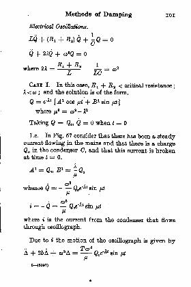
Methods of Damping 101
Electrical Oscillations.
Q + 21Q + a)*Q =
i ~ -"i ~h -Sfl 1where 2x = = o>
2
JL/ Z/C7
CASH I. In this case, J?! + R^ < critical resistance;
A < o> ;and the solution is of the form.
Q = e~*' {A1 cos pt + J?1 sin fit }
where /*2 = co
2 - A2
Taking (3= Q , Q = when t =
I.e. In Fig. 57 consider that there has been a steadycurrent flowing in the mains and that there is a chargeQ in the condenser C, and that this current is brokenat time t = 0.
i_ i _ *
^
o>2
..
whence Q = Q e s111 V&/*
f e sin IM
where t is the current from the condenser that flows
through oscillograph.
Due to i the motion of the oscillograph is given by
A + 26A + o)2A = Qo6
'^*siti ut
P8 (5307)
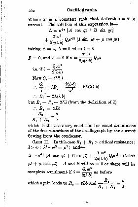
102 Oscillographs
"Where T is a constant suoh that deflection = T xcurrent. The solution of this expression is
A = &'bt[A cos qt + B sin qt}
Tea*+ TTTM &e
~A '
(A sin ^ + <" oos ^2
/u(A-o)
taking A = a, A = when t =
B = 0, and .4 = if a =
Now Q =
t cu
.-. J?!= 2L(A-6)
tut J?! + J2, = 2LA (from the definition of
/. RI = 2U
JUj + .Bj A
which is the necessary condition for exact annulmentof the free vibrations of the oscillograph by the current
flowing from the condenser.
CASH II. In this case J? x + R z> critical resistance
;
X > co;Xz - Q)
Z =jj? ;
and
A = e-6 '
(A cos qt + B sin qt} + Q e^' (Asinh
-\- fj,cosh /rf). ^1 and 5 will be = or there will be
for
7?
/") -fi
complete annulment if t = , ,as before
which again leads to R t= 2Lb and--
-Si +

Methods of Damping 103
If, therefore, an adjustment be found for any onevalue of R 1 the value of R z will remain the same forall values of R^.
TO -L
For state of dead beat ==
jffj + RI CO
The value of b can also be found directly. The periodO_ O_of the oscillograph being or approximately
The ratio of successive amplitudes = = g~6 ~
CO
therefore b = logco a,
co /aA a,o = o-log ( I = frequency x log
+rtT \l*l/ CL 2
6 being known R t= 2Lb
and R t is now fixed for all variations of R lf
Up to the present we have been considering caseswhere the only shunt to the oscillograph is the resonantshunt. Where the instrument is used to record largecurrents the shunt in the main circuit is also shuntingthe oscillograph as shown in Fig. 58 and, as the resist-
ance of this shunt is almost always negligible comparedwith that of the oscillograph, we can neglect it in con-
sidering the discharge of the condenser C through the
oscillograph and the shunt in parallel. If an additionalconstant resistance r be placed between the main shuntand the oscillograph, a portion r/(r + RJ of thecurrent from the condenser flows through the oscillo-
graph, therefore we have to increase the capacity to
(r + RJ/r of what it was before. Then, to keep the
frequency constant, the induction L becomes r/(r -f-

Oscillographs
what it was before. Also, jR 8 becomes J?,1
, where
= Rz X r/(r + E^. Now JRj. and r in parallel give
jsistanoe to the condenser discharge R X r/(r -f Ej),
that the total resistance to the discharge of the oon-
iser is RJ- R- -. -=-r which is of the-
-L -.
(r
.ue of -Ri + RI-
[f, as practical values,
-f-
fc
\'
r = JJj then the capacity,
inductance, and resistance
would be altered in the
correct proportions if an
exactly similar resonance
shunt were placed in
parallel with M t , 0, and
L, and connected as shown
by the dotted lines in
Pig. 68. The same result
would be attained if the
capacity were doubled
and the resistance _5 2 an(i
the inductance L were
halved. The dampingnild vary, however, if the value of r were altered to
ry the magnitude of the deflection ; thus, if r were
ried from 0-5r to l-6r (where r is the value giving
tioal damping) the damping would be varied from
J6 of critical damping to 1-2 time critical, which
>uld be less than the variation produced by oil
mping owing to variation of viscosity with temper-
ore.
Resonant Shunt Damping for Electrostatic OscUlo-
ELphs. This method of damping an electro-magnetic
olllograph can also be applied to electrostatic
\,. 68.-OsOHiOaBAPH, WITHsoNAira SHUNT, OONITBIOTBD
loss SBTUNT IN MATNT Qroauir
GIVD THU WAVE FOBM OFTJJJJ MAHT OUBHBINT

Methods of Damping 105
instruments. Thus, in Pig. 59, if an electrostatic oscillo-
graph E.O. were placed in parallel with the electro-
magnetic oscillograph, the electrical forces applied tothe moving part of the electrostatic oscillographwould be proportional art every instant to the forces
applied to the electro-magnetic instrument so long asthe resistance R was truly non-inductive and had no
appreciable back-E.M.F. induced in it.
FIQ. 89. RESONANT-SHUNT DAMPING APPLIED TO ANEufflOTBOSTATICJ OSOTLLOQRAPH
If, therefore, the electrostatic oscillograph be madeof the same frequency as the electro-magnet instrument,and has the same ratio of actual damping to critical
damping, it can be made dead beat, under-damped, or
over-damped by varying R lt just as in the case of theelectro-magnetic oscillograph. In practice, JR^ wouldbe made a very high resistance and this means thatR a and L would also be very large, and the capacityC would be very small.
Let us consider the case of an electrostatic oscillo-
graph of a capacity 40 X 10 6pF, with a resonant
frequency of 2000, and suppose that the damping outof oil is one-twentieth of the critical value.
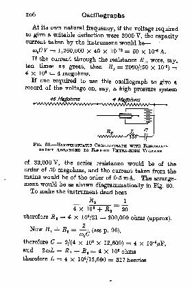
106 Oscillographs
At its own natural frequency, if the voltage requiredto give a suitable deflection were 2000 V, the capacitycurrent taken by the instrument would be
co CV = 1,260,000 X 40 X lO'18 = 60 X lO"8 A.
If the current through the resistance JR 1} were, say,ten times as great, then E :
= 2000/(50 x 10'6)=
4 x 106 = 4 megohms.If one required to use thig oscillograph to give a
record of the voltage on, say, a high pressure system
46 Megohms 4 M&bhms
R* L M Ivs/wwvw rnnr '
FIG. 80. ELBOTKOSTATIO OSOILLOGBJLPH WITH RBHONANT-ABBANGED TO RHOOBD EXTRA-HIGH VOLTAGE
of 33,000V, the series resistance would be of theorder of 60 megohms, and the current taken from themains would be of the order of 0-5 mA. The arrange-ment would be as shown diagrammatically in !Pig. 60.
To make the instrument dead beat
__4 x 10 -h R z
~'20
therefore R 2= 4 x 10⁶
/21 = 200,000 ohms (approx).
2Now RI + RI = -
(see p. 96),co C
therefore =2/(4 x 108 x 12,600) = 4 X 10'VF,
and 2coL = J2 a + JJ! 8= 4 x 10 fl ohms
therefore L = 4 x 10⁶/12,600 = 317 henries

Methods of Damping 107
a value whioh, although iigh, is fairly easily attainable
with the fine wire now available.
The advantage of a resonant shunt for damping anelectrostatic oscillograph is that it makes the dampingindependent of the dielectric medium, whioh can there-
fore be chosen for reasons other than damping. Thus,
compressed air, or any gas, could be chosen instead of
FIG. 61. RESONANT SHUNT USHD WITH ELBOTBO-MAQNBTIO OsnTTiTiOGRAPH, AND WITH A CONDHNSHBSHUTTING THE SBBIHB RESISTANCE TO INCREASE THMRANGE OP FREQUENCY OVHB WHICH THE INBTBUMBNT
CAN BE USED
oil. If a very high vacuum be used the dielectric
strength can be increased to, say, twenty times thatof air or, say, seven to ten times that of oil, and this
will make possible frequencies for electrostatic instru-
ments as high as for electro-magnetic.
Working Range of Frequency with Resonant-shunt
Damping. Since the resonant shunt method of damp-ing gives a means of producing less than or more thancritical damping at will, it opens up a new method of
increasing the range of frequency over which an
oscillograph can be used.
If an oscillograph of the electro-magnetic type beused to indicate the pressure between two points AB,Fig. 61, and if the value of JR-^ be adjusted to give, say,

io8 Oscillographs
twice critical damping the curve of magnification fortwice critical damping given in Kg. 51 would applyto the instrument and, at its own resonant frequency,the amplitude of the vibrations would only be onequarter of the amplitude given by the same pressurevariation at very low frequencies.
If, however, the series resistance B be shunted by acapacity Ca the magnitude of the current taken fromthe mains when R is very large compared with
becomes EJ(coC.)* +(I)"
instead of|, therefore, if
the ratio of co to o> = k as before the ordinary magni-fication of amplitude for an oscillograph
1
-2)
becomes
since co = ko>.
If the ratio of o> C. to I/ E, i.e. the ratio of thecurrent taken by the condenser O, to the current takenby the series resistance JR at the resonant frequency ofthe oscillograph, be called q
Then the magnification = /'V
+ 1
If n, the ratio of damping to critical damping = 2,and if we make k the ratio of frequency to resonant
/
/ QI i
frequency = 1, the magnification = / g +

Methods of Damping 109
Thus, at the resonant frequency, if the magnification= Lq* + 1 = 16
and q = 3-87
If q = 4 the magnification at resonant frequency = 1-03
tt> 1-2 1-4 f-ff 1-9 20 23 24 2* _Ratio ofactual to rssorwit fivqioncy ->
FIG. 62. ODBVBS SHOWING MAGNIFIOATION AND LAO OPQsmTiTrOGBAPH DHPUBOTION AT VABIOUS FBEQUKNOXHSWITH TWIOH QainaAii DAMPING, AND WITH A CONDHNSHR
SHUNTING THH SHBDDS RBSISTANGSI
If we take q = 4 and n = 2, and plot the values of
from k = to k = 3 we get
JL-L
J -2)
a curve as shown in Fig. 62.
It will be seen that the variation of magnification(posititfB' or negative) nowhere exceeds 5-5 per centover a range of frequency from to twice the resonant
frequency of the instrument and that even at three
.times the resonant frequency the reduction of ampli-tude is only 16-6 per cent, whereas the same instrument
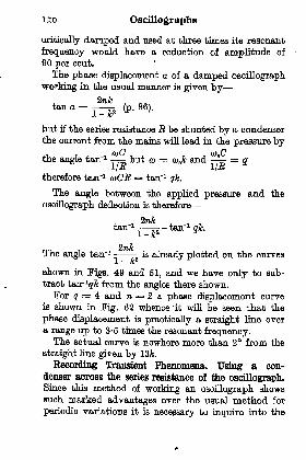
no Oscillographs
critically damped and used at three times its resonant
frequency would have a reduction of amplitude of
90 per cent.
The phase displacement a of a damped oscillograph
working in the usual manner is given by
tan a =^- (p. 86).
but if the series resistance R be shunted by a condenserthe current from the mains will lead in the pressure by. , i A i -. , 7 j othe angle tan'1 - but CD = co k and -j
= ql/-n L/JR
therefore tan'1 coCR = tan'1 qk.
The angle between the applied pressure and the
oscillograph deflection is therefore
* 1 4- 1 7tan 1 - - tan'1qk.
1-fc2
i
The angle tan' 1 - is already plotted on the curvesJL
~ 1C
shown in Figs. 49 and 51, and we have only to sub-
tract tanr 1^ from the angles there shown.For q = 4 and n = 2 a phase displacement curve
is shown in Fig. 62 whence it will be seen that the
phase displacement is practically a straight line over
a range up to 3-5 times the resonant frequency.The actual curve is nowhere more than. 2 from the
straight line given by 13k.
Recording Transient Phenomena. Using a con-
denser across the series resistance o! the oscillograph.Since thip method of working an oscillograph showssuch marked advantages over the usual method for
periodic variations it is necessary to inquire into the

Methods of Damping in
performance of the instrument when subject to transient
phenomena.It is necessary to consider the order of magnitude
of the various portions of the electrical circuit shown in
Fig. 61. If RI be the resistance of the oscillographtin's can be made, say, of the order of 6 ohms.
If a current of 0- 1 A gives a large enough deflection
then, on a voltage of 100, the series resistance jR is
1000 ohms. If the oscillograph have a resonant fre-
quency of 4000 then in the above case, where toC^t = 2
2 1611 '
=1000 X 27T X 4000
=~n^'
If a steady voltage V be applied suddenly across the
terminals AB (Fig. 61), the condenser O a is charged
through the resistance J?x of the oscillograph and the
charge Q in the condenser at any time t from the
application if the voltage is given, in terms of the final
charge VCn by the equation
Q= FC^l-e-Wi).
. In the present case,C^ = X 10'6 X 5 = 4 x 10'7
and if t = 4 X 10'7second, then (1-e^ ^) = 0-63
i.e. the condenser acquires 63 per cent of its charge in
less than half a millionth of a second.
In one-millionth of a second the condenser acquires
about 92 per cent of its complete charge, that is to
say in a time very short compared with the frequency
of the oscillograph the charge C,V will flow into the
condenser. This charge will give an impulse to the
oscillograph strips per unit length, equal to Ct(|7/1 0)5,
where B is the strength of the magnetic field in which
the strips are placed. If m be the mass per unit
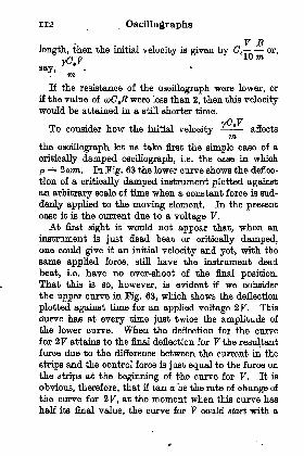
H2. Oscillographs
V Blength, then the initiH.1 velocity is given by Ot
--or,
yC.V10 m
If the resistance of the oscillograph were lower, or
if the value of coCgR were less than 2, then this velocitywould be attained in a still shorter time.
vO VTo consider how the irdtnal velocity
'affects
the oscillograph let us take first the simple case of a
critically damped oscillograph, i.e. the case in which
p == 2 com. In Fig. 63 the lower curve shows the deflec-
tion of a critically damped instrument plotted againstan arbitrary scale of time when a constant force is sud-
denly applied to the moving element. In the presentcase it is the current due to a voltage V.
At first sight it would not appear that, when an
instrument IB just dead beat or critically damped,one could give it an initial velocity and yet, with the
same applied force, still have the instrument dead
beat, i.e. have no over-shoot of the firml position.That this is so, however, is evident if we consider
the upper curve in Fig. 63, which shows the deflection
plotted against time for an applied voltage 2V. This
curve has at every time just twice the amplitude of
the lower curve. When the deflection for the curve
for 2V attains to the fina.l deflection for V the resultant
force due to the difference between the current in the
strips and the control force is just equal to the force onthe strips at the beginning of the curve for V. It is
obvious, therefore, that if tan a be the rate of change of
the curve for 2 V, at the moment when this curve has
half its final value, the curve for V could start with a
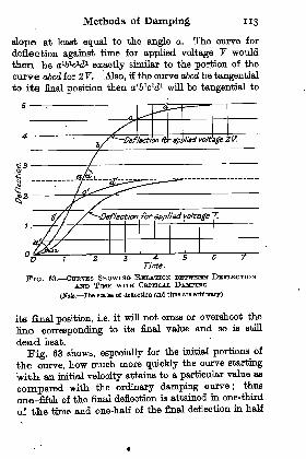
Methods of Damping
slope at least equal to the angle a. The curve for
deflection against time for applied voltage V would
then be a1^1^1 exactly similar to the portion of the
curve abed for 2 V. Also, if the curve abed be tangential
to its final position then a161c1d1 will be tangential to
FIG. 63. OtnavES SHOWING RELATION BHTWHHIN DBTFLHOTION
AND TUCB WITH CBITiaAL DAMPINO
(NoU. The scales of deflection and time are arbitrary)
its final position, i.e. it will not cross or overshoot the
line corresponding to its final value and so is still
dead beat.
Fig. 63 shows, especially for the initial portions of
the curve, how much more quickly the curve starting
'with, an im'tnal velocity attains to a particular value as
compared with the ordinary damping curve; thus
one-fifth of the final deflection is attained in one-third
of the time and one-half of the final deflection in half
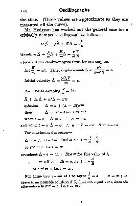
ii4 Oscillographs
the time. (These values are approximate as they are
measured off the curve).
Mr. Hodgson has worked out the general case for a
critically damped oscillograph as follows
VmA + flA + -B7A = y=
a Atherefore A + A + -A -5where y is the electro-magnet force for one ampere.
.ZT yVLet = o)
1. Final displacement A =-r = am mto'Jt
Initial velocity A = = tt.
vn>
For critical damping = 2o>
A + 2coA + to'A = to'a
solution A = a + (A +then A = (B - Aca -
when l = o A = o .". .4 = a
and when f = oA = tt .'. u = B -\- aw B = u- aco
For TnaximnTn deflection
. 1 AA = o .'. B - Aca - Bcot = o or i = -- -=
or d"1"* = o, i.e. f = oo
overshoot A -a = (A -{- Btfe-"* for this value of t,
= oif ^ +B( =
or~w( = o, i.e. f = oo .
For these two values of t to agree = o .". <o = co ; i.e.CO
there is no possible solution if CB does not equal zero, since the
alternative is f* = o, i.e. * = oo .
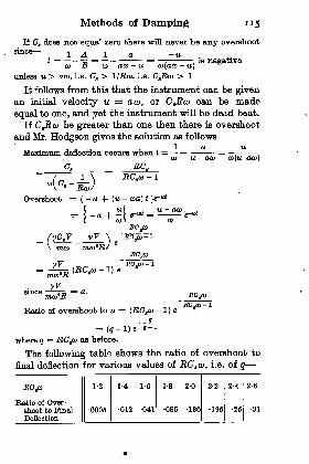
Methods of Damping
If Ct does not equal zero there will never be airy overshoot8inoe
1 A 1 a -ut = = = = . is negative
to B co aco u (o(cua it)
nnlftgfl u > aco, i.e. Cs > I/Rco, i.e. C^Etco > 1
It follows from this that the instrument can be givenan iT)itiH.1 velocity u = aco, or CJRco can be made
equal to one, and yet the instrument will be dead beat.
If CgRot) be greater than one then there is overshoot
and Mr. Hodgson gives the solution as followsla t*
Maximum, deflection occurs when t =|
=;
co u- aco to(u-aco)
C. RCa
. .
6-"*
Overshoot ={- a + (u - coa) t
u ) ^^ u- aco
0)) CO
ROjo
mco mco'R
vV7(RCtco-l) e
- 1
sinceROjo
Ratio of overshoot to a = (RCsco-
1) e
where q = RCsco as before.
The following table shows the ratio of overshoot to
final deflection for various values of RGt a>, i.e. of q
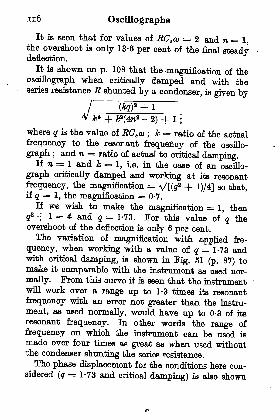
n6 Oscillographs
It is seen that for values of RCtco = 2 and n=l,the overshoot is only 13-6 per cent of the final steadydeflection.
It is shown on p. 108 that the magnification of the
oscillograph when critically damped and with theseries resistance E shunted by a condenser, is given by
+ F(4na -2) + 1
;
where q is the value of RCa a> ; k = ratio of the actual
frequency to the resonant frequency of the oscillo-
graph ;and n = ratio of actual to critical damping.
If n = 1 and & = 1, i.e. in the case of an oscillo-
graph critically damped and working at its resonant
frequency, the magnification = V[(tf2 + l)/4] BO that,
if q = 1, the magnification = 0-7.
If we wish to make the magnification = 1, then
g2 + 1 = 4 and q = 1-73. For this value of q theovershoot of the deflection is only 6 per cent.
The variation of magnification with applied fre-
quency, when working with a value of q = 1-73 andwith critical damping, is shown in Fig. 61 (p. 87) tomake it comparable with the instrument as used nor-
mally. From this curve it is seen that the instrumentwill work over a range up to 1-3 times its resonant
frequency with an error not greater than the instru-
ment, as used normally, would have up to 0-3 of its
resonant frequency. In other words the range of
frequency on which the instrument can be used is
made over four times as great as when used withoutthe condenser shunting the series resistance.
The phase displacement for the conditions here con-sidered (q = 1-73 and critical damping) is also shown
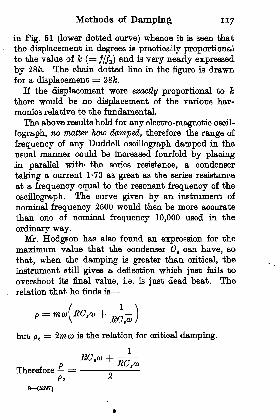
Methods of Damping 117
in Fig. 51 (lower dotted curve) whence it is seen that
the displacement in degrees is practically proportionalto the value of k (= ///E) and is very nearly expressed
by 28&. The chain dotted line in the figure is drawnfor a displacement = 28fe.
If the displacement were exactly proportional to k
there would be no displacement of the various har-
monics relative to the fundamental.
The above results hold for any electro-magnetic oscil-
lograph, no matt&r how damped, therefore the range of
frequency of any Duddell oscillograph damped in the
usual manner could be increased fourfold by placing,in parallel with- the series resistance, a condenser
taking a current 1-73 as great as the series resistance
at a frequency equal to the resonant frequency of the
oscillograph. The curve given by an instrument of
nominal frequency 2600 would then be more accurate
than one of nominal frequency 10,000 used in the
ordinary way.Mr. Hodgson has also found an expression for the
maximum value that the condenser C, can have, so
that, when the damping is greater than critical, the
instrument still gives a deflection which just fails to
overshoot its final value, i.e. is just dead beat. The
relation that he finds is
but PO= 2m o> is the relation for critical damping.
pTherefore - =
(6397}
RC aco
=PC
Oscillographs
or, denoting by n\ and RCt ai by q ;
Po
2n = q -\- -.
Q.
On p. 109 there is a case worked out for n = 2 andq = 4, i.e. with n = 2 instead of (4 + J)
= 2-126 which,is the value necessary to give no overshoot, and thecurve is shown in Fig. 62.
It is well known that, when the .damping is verynearly critical, under a given condition of working, acomparatively large variation in p will not affect thevalue of the overshoot to any noticeable extent, there-fore the oscillograph so arranged would show noappreciable overshoot.
Curves could be drawn for values of q plotted againstn for critical damping and curves obtained similar tothose in Fig. 62 'for particular values of n and q.For higher values of q, n can be taken as half q
without any serious error, thus if q = 10 the valuen = 5. is within 1 per cent of the true value.In such a working of the
oscillograph the controldue to damping forces has been made very largecompared with the inertia and control forces.
In the preceding oases the results were worked outfor an electro-magnetic oscillograph used to indicatethe pressure between two points in a circuit. Theconditions are altered when the instrument is usedto indicate the current flowing in a circuit and wherethe instrument is used as a shunt to a resistance. Itis evident that the resistance must now have self-
induction as well as resistance and, if the current andpotential curves are to be exactly comparable,
Methods of Damping 119
ratio of the reaction to the resistance voltage mustbe equal to the ratio a)CJ(l/R) ;
i.e. coL/R, = coOgR ;
where L is the self induction of the resistance used as a
shunt, and R a its resistance.
It might be considered at first somewhat troublesometo adjust the resistances in the main circuit to havethis value of coL/Ra but, except for the resistance shuntsfor small currents, the resistance will have nearlyenough self-induction. Thus, if oOgR q = 2, thenfor a shunt to give 1 V drop for a current of 50 Ao)L/R t
= cuCgR = 2; R, = 0-02
; and o>L = 0-04.
Hence, if o> = ZTT, 4000 = 25,000 (i.e. if resonance fre-
quency = 4000) L = 1-6 microhenries.
A single turn of No. 14 S.W.G. wire, in the form of a
square of 10 cm. side, would have an inductance of
about 0-4 microhenry, and less than three suchturns of wire would be required to give the neces-
sary inductance. A simple mutual inductance couldalso be arranged to have the necessary ratio of MtoR.
Practical Conclusions Regarding Range and Error of
Oscillographs. To come to practical results in con-nection with the errors due to oscillographs it is
sufficient at present, to say that an Einthoven galvano-meter or oscillograph, in which there is no loading of
the wire by a mirror, fulfils the above theory veryexactly, but an oscillograph of the bifilar type does notconform so closely.
The one reason for t.Tiis is that a bifilar instrumenthas generally two essential periods of vibration as it
is almost impossible to arrange the two wires to have
equal tensions, and to place the mirror absolutely
symmetrically across the wires. There may also be
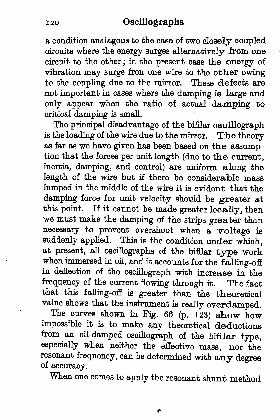
120 Oscillographs
a condition analagous to the case of two closely coupledcircuits where the energy surges alternatively from one
circuit to the other;in the present case the energy of
vibration may surge fron one wire to the otlier owingto the coupling due to the mirror. These defects are
not important in cases where the damping is large and
only appear when the ratio of actual damping to
critical damping is small.
The principal disadvantage of the bifilar oscillographis the loading of the wire due to the mirror. Tiie theoryas far as we have given has been based on the assump-tion that the forces per unit length (due to the current
,
inertia, damping, and control) are uniform along the
length of the wire but if there be considerable mass
lumped in the middle of the wire it is evident that the
damping force for unit velocity should be greater atthis point. If it cannot be made greater locally, thenwe must make the damping of the strips greater than
necessary to prevent overshoot when a voltage JB
suddenly applied. This is the condition under which,at present, all oscillographs of the bifilar type workwhen immersed in oil, and it accounts for the falling-offin deflection of the oscillograph with increase in the
frequency of the current flowing through it. The factthat this falling-off is greater than the theoreticalvalue shows that the instrument is really overdamped.The curves shown in Fig. 66 (p. 123) show how
impossible it is to make any theoretical deductionsfrom an oil-damped oscillograph of the bifilar type,especially when neither the effective mass, nor theresonant frequency, can be determined with any degreeof accuracy.When one comes to apply the resonant shunt method
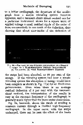
Methods of Damping 121
to a bifilar oscillograph, the departure of the oscillo-
graph from a simple vibrating system becomes
apparent, and a resonant shunt circuit worked out for
a particular instrument shows for a square wave of
applied voltage a small residual ripple of the order of
from one-twentieth to one-tenth of the deflection, thus
showing that about nine-tenths of the deflection of
Fio. 64. RHCOBDS op THE STJDDHN APPLICATION CF A STEADYCUBBHNT TO A HiaH-FBEQCENCY BoTLAR OSCTLLOQSAPH
(a) UNDAMPED, (b) WITH REflONANT-SEnjNT DAMPING
the strips had been absorbed, or 99 per cent of the
energy. If the vibrating system had been a simple
vibrating system the absorption of energy would have
been complete as shown in Fig. 17 (a) for an Einthoven
galvanometer. Even when there is an averageresidual deflection of 8 per cent with the resonant-
shunt method, the interpretation of the results is
easy as the resonant frequency of the oscillograph is
generally much higher than the wave under observation.
Fig. 64, herewith, shows the result of sending a
constant current through a Duddell high-frequency
oscillograph. In the upper curve, with the strips
undamped, there can be seen the effect of the beats

122 Oscillographs
between the two wires. At the moment of breakowing to the extremely rapid movements of the spotthe curve is very faint. In the lower curve the effectof using the oscillograph with a resonant shunt is
FlG. 06. -JttfflOOliDH OBTAINED WITH A MlGH-FBEQUBNOYEmma OSCILLOGRAPH CBITIOALLY DAMPED (a) WITH On(6) BY A RESONANT SHTTNT
clearly shown, the general outline following the usual
damping curve for an oscillograph, but showing smallresidual vibrations for reasons already explained. TheTrmTinmTn value of these vibrations is about 5 percent of the initial displacement, and this value of 5 percent is nearly twice what would be produced if therewere no beats between the two wires. When takingthis record Fig. 65(6) the oscillograph was over-dampedin order to show the curve more clearly, but the amountof the damping can be varied easily at will.

Methods of Damping 123
Fig. 65 is reproduced from two oscillograph, records
taken on the same plate, showing the results obtained
(a) by a high-frequency Duddell oscillograph critically
damped by oil (upper curve) ; and (6) by the same
type of oscillograph, damped by a resonant shunt
400 800 12DO 1600 WOO MOO 2800
Frequency ofcurrent, cycles per sec.
320O S6OO
FIG. 66. CujiVJflB SHOWING RELATION BETWEEN AMPLITUDEOF VlBBATION AND iFsEQITHINCrY Off CtnaBHNT IN A BUTTitTt
OSCILLOGRAPH WITH. OlL DAMPIKG AT VABIOU8 TEMPHSATTJBBS,AND WITH RESONANT-SHUNT DAMPING
(lower curve). In spite of the great irregularity in
the curve the two records are almost exactly similar ;
actually the peaks are slightly higher with the resonant
shunt. As the highest important harmonic in the
record has a frequency not exceeding 1000, one would,
of course, expect the records of both elements to be
identical and true. It is only when the frequencies
are much higher, and near the resonant frequency, that
one observes a discrepancy.
In Pig. 66 is shown the performance under various
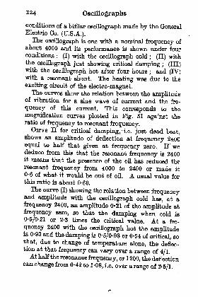
I24 Oscillographs
conditions of a bifilar oscillograph made by the GeneralElectric Co. (U.S.A.).The oscillograph is one with a nominal frequency of
about 4000 and its performance is shown under fourconditions : (I) with the oscillograph cold
; (II) withthe oscillograph just showing critical damping ; (III)with the oscillograph hot after four hours
;and (IV)
with a resonant shunt. The heating was due to the
exciting circuit of the electro-magnet.The curves show the relation between the amplitude
of vibration for a sine wave of current and the fre-
quency of this current. This corresponds to the
magnification curves plotted in Pig. 61 against theratio of frequency to resonant frequency.
Curve n for critical damping, -i.e. just dead beat,shows an amplitude of deflection at frequency 2400equal to half that given at frequency zero. If wededuce from this that the resonant frequency is 2400it means that the presence of the oil has reduced theresonant frequency from 4000 to 2400 or made it
0-6 of what it would be out of oil. A usual value forthis ratio is about 0-66.
The curve (I) showing the relation between frequencyand amplitude with the oscillograph cold has, at afrequency 2400, an amplitude 0-21 of the amplitude at
frequency zero, so that the damping when cold is
0-5/0-21 or 2-3 times the critical value. At a fre-
quency 2400 with the oscillograph hot the amplitudeis 0-93 and the damping is 0-5/0-93 or 0-54 of critical, sothat, due to change of temperature alone, the deflec-tion at that frequency can vary over a range of 4/1.At half the resonance frequency, or 1200, the deflectioncan change from 0-42 to 1-08, i.e. over a range of 2-5/1.
Methods of Damping 125
On the other hand, the same instrument used witha resonant shunt, curve (TV) , has up to 2000 frequency a
maximum change of amplitude of 6 per cent, corre-
sponding to a condition of damping between half andfull critical damping, and it will remain constant at
all temperatures.The principal conclusions to he drawn from these
results are
(1) Tiffing an oscillograph damped in the usual way :
(a) it is advisable for the series resistance to have a
capacity effect either inherent or added;and (6) the
shunts in the main circuit should be inductive, not
non-inductive.
(2) Using a resonant shunt for damping purposeshas very considerable advantages as it does not reduce
the resonant frequency of the oscillograph and the
damping can he made adjustable and definite. In
this case also : (a) there should be a capacity shuntingthe series resistance ;
and (b) the shunts in the maincircuit should be made inductive.
(3) An electrostatic oscillograph can be damped bya resonant shunt and can be placed in a high vacuumto enable large electrical stresses to be employed.
CHAPTER IV
THE OATHODH BAY OSCILLOGRAPH
General Principle. The cathode ray oscillograph \\
first developed by Braun and is sometimes spoken ofa Braun Tube. It depends on the principle that a stret
of negative corpuscles can have their path deflected
either an electro-magnetic or an electrostatic field.
If a highly exhausted glass tube such as shownFig. 67 has a cathode plate K sealed into one end a,:
a anode plate A some distance along the tube, th.c
when a high enough voltage is applied between t
plates K and A, an electrical discharge will pass a:
this discharge will be carried in the tube chiefly 1
very minute bodies called electrons, each of whicarries a negative charge of electricity. Sometircthe charge and its associated body is called an eleotrcAs the current is carried chiefly by negative oharg
these will be discharged against A with great velocitand if there is a pin hole in the centre of A some of t]
electrons will be projected through t.T-n'a opening dcrva small tube t. In their flight they will pass : (
between a pair of parallel plates PP with their pla:horizontal
; and (2) between a pair of plates QQ witheir plane vertical and will eventually strike tl
screen S and cause fluorescence.
An electrostatic field can be established between t]
plates PP or between the plates QQ ;and a pair
coils CO can produce a magnetic field superimposed <
the electrostatic field due to the plates QQ.126

The Cathode Ray Oscillograph 127
Dynamics of the Braun Tube. A body of mass ra,
carrying a charge e, measured in electrostatic units will
be subject to a force in an electrostatic field given byeE, where E is the strength of field in electrostatic
units, the direction of this force will be along the lines
of force. If the body has motion at right angles to a
magnetic field it will also have a force acting on it
at right angles to its motion and to the magnetic field.
(a,)
FIQ. 67. DIAGRAMMATIC REPRESENTATION OP THETUBE
Force and Motion in a Magnetic Field. In consider-
ing this case, let all measurements be made in electro-
magnetic units. A charge e moving at a velocity v is
the equivalent of a current of ev and the force in dynes on
a conductor carrying this current would be evB per unit
length, where B is the intensity of the magnetic field.
If the moving charge has a length of path in the
magnetic field = A, the time "during which the force
evB acts is A/v, and the displacement d^ from the
initial straight line during this time will be
evB tf
'*= **= a +
The velocity impressed on the moving charge by the
"D 1
macnetio field is -- so that if the charged body has^ m v
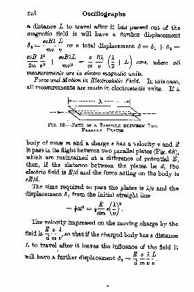
138 Oscillographs
a distance L to travel after it has passed out of the
magnetic field it will have a further displacementevBX L
o t-- or a total displacement <5 = 6, 4- <5 =mv v IIB
&vB A2 evBAL e BX X
measurements are in electro^nagnetic units.
Force and Motion in Electrostatic Held. In this case,all measurements are made in electrostatic units. If a
h--------- A, --------H
FIG. 68. PATH ov A PABTIOLH BHTWTEHN TwoPLATBS
body of mass m and a charge e has a velocity v and if
it pass in its flight between two parallel plates (Pig. 68),which are maintained at a difference of potential E,then, if the distance between the plates be d, theelectric field is E/d and the force acting on the body isJ
The time required to pass the plates is A/v and thedisplacement <5 t from the initial straight line
*dm \v/'
The velocity impressed on the moving charge by the
field is - -,so that if the charged body has a distance
L to travel after it leaves the influence of the field it
E f 1 Twill have a further displacement (5,
= - ~ -.
d m v v
The Cathode Ray Oscillograph 129
rr i / j\
Total displacement 6 = ^ + 6^ = (. + -)E e A / A\
m= T (
L -| )cms. where att measurements are in
vzm a \ 2J
electrostatic units. The value of e/m for cathode rays =5-316 X 1017 electrostatic unite or 1-772 x 107 electro-
magnetic units.
The velocity v given to the electrons is determined
by the voltage between the cathode and anode plates.
If we keep in mind the fact that the work done on a
body, in moving it from a plate at one potential to
another at a different potential, is independent of the
path taken and depends only on the charge on the bodyit is easy to calculate the velocity of the moving
corpuscles.
If the distance between the cathode and anode
Fplates is D, the field in electrostatic units is . The
Ve'
Veforce on the electron is the acceleration = ^ and
D . DmV e T7
e
v* = 2 x acceleration X D = 2 - D = 2FD m m
Itherefore v = J 2V .
'r m
If _ = 5-316 X 1017
m _v = 10-3 X 10⁸VF
If F! be measured in volts then
v = 10-3 x 10V "no= 6 ' 95 X 10?
This assumes that no energy is spent in tearing away
130 Oscillographs
the electrons from the cathode, or absorbed due to
viscosity in the medium through which they pass.Sensitivity of the Braun Tabe. We are now in a
position to calculate the sensitivity under any givencondition.
In the tube shown in Fig. 67 when a stream ofelectrons is projected at a high velocity against Asome of them will pass through a small aperture in thecentre of the plate. A diaphragm with a hole in thecentre, or else a pinhole tube as shown at t, Fig. 67,is interposed between the anode A and the screen 8on which the stream of electrons (or
"cathode ray ")
falls; this is to cut off secondary radiation and light,
and to confine the pencil of rays and the spot to a smalldiameter.
Case (a) Electro-magnetic Operation. If the cathoderay, after passing the diaphragm, pass into a magneticfield of uniform strength and if the strength is uniformfor a distance of 10 cm. and then the rays travelanother 20 cm. before they strike the screen, the dis-
placement is
If Vt
= 10,000V, velocity of electrons = 5-95 x 10B,
, . 1-772 X 10'***' =
5-95 x 103B X 25 = ^55cm.
or approximately 7-6 mm. for unit strength of magneticfield.
If we assume that the field B is produced by twolong coils (Fig. 69) one on each side of the tube and,say, 12 cm. long by 2-5 cm. wide, then if placed 2-5 cm.
apart the field horizontal at the centre will be given

The Cathode Ray Oscillograph 131
by 0-32 i n where i is the current in amperes and n =the number of turns in each coil. If n = I, that is
with a single turn, the value of B would be 0-32 with one
ampere and the deflection would be about 2-6 mm.If the current required to be studied were of the
order of 0-1 A, R.M.8., the number of turns would be
120 (this would give a deflection of 42-3 mm. on each
FIG. 69. DIMBINSIOKS OF COILS PBODUOINQ EUEOTBO-MAONUTIO FIELD rw THE BaAtnr TUBH aoNsrDHSHD
IN THE THXT
side of zero), and the value of the self induction would
be about 3 millihenries. At a frequency of 1000 this
would give a reactive voltage = 1-75 V;at a frequency
of 10,000 the voltage required would be 17-5;and at
100,000 frequency the voltage would be 176 V. The
current sensitivity would be 1 mm. for about 0-003 A.
Case (b) Electrostatic Operation. To take an
example for the same oscillograph operating on the
electrostatic forces
If the speed of the corpuscles be the same as before,
and if the electrostatic plates be 10 cm long and 1 cm.
apart, i.e. A = 10, d = 1, and if L = 20 as before, then :
Displacement of spot under electrostatic field
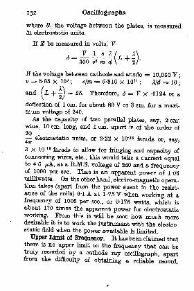
132 Oscillographs
where E, the voltage between the plates, is measuredin electrostatic units.
If E be measured in volts, VV I e A
<5 = ---300 va m d
If the voltage between cathode and anode = 10,000 V ;
v = 5-95 x 10B; e/m = 6-316 x 1017
;Md = 10
;
and(L + -) = 25. Therefore, 6 = V X -0124 or a
\ &l
deflection of 1 cm. for about 80 V or 3 cm. for a maxi-mum voltage of 240.
As the capacity of two parallel plates, say, 2 cnr.
wide, 10 cm. long, and 1 cm. apart is of the order of
20,
electrostatic units, or 2-22 x 10'12 farads or, say,
3 x 10'18 farads to allow for fringing and capacity of
connecting wires, etc., thip would take a current equalto 4-5 pA, at a R.M.S. voltage of 240 and a frequencyof 1000 per seo. That is an apparent power of 1-08milliwatts. On the other hand, electro-magnetic opera-tion takes (apart from the power spent in the resist-
ance of the coils) 0-1 A at 1-76 V when working at a
frequency of 1000 per sec., or 0-175 watts, which is
about 170 times the apparent power for electrostatic
working. From this it will be seen how much moredesirable it is to work the instrument with the electro-static field when the power available is limited.
Upper Limit of Frequency. It has been claimed thatthere is no upper limit to the frequency that can betruly recorded by a cathode ray oscillograph, apartfrom the
difficulty of obtaining a reliable record.
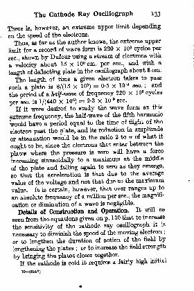
The Cathode Ray Oscillograph 133
There is, however, an extreme upper limit depending
on the speed of the electrons.
Thus, as far as the author knows, the extreme upper
limit for a record of wave form is 220 X 10 cycles per
sec., shown by Dufour using a stream of electrons with
a velocity about 16 X 109 cm. per sec., and with a
length of deflecting plate in the oscillograph about 8 cm.
The length of time a given electron takes to pass
such a plate is 8/(15 X 109)= 0-5 x 10'8 sec. ;
and
the period of a half-wave of frequency 220 X 10 cycles
per sec. is 1/(440 X 10 a)= 2-3 x 10'9 sec.
If it were desired to study the wave form at this
extreme frequency, the half-wave of the fifth harmonic
would have a period equal to the time of flight of the
electron past the plate, and its reduction in amplitude
or attenuation would be in the ratio 2 to TT of what it
ought to be, since the electrons that enter between the
plates where the pressure is zero will have a force
increasing sinusoidally to a maximum at the middle
of the plate and falling again to zero as they emerge,
so that the acceleration is that due to the average
value of the voltage and not that due to the maximum
value. It is certain, however, that over ranges up to
an absolute frequency of a million per sec., the magnifi-
cation or diminution of a wave is negligible.
Details of Construction ajad Operation. It will be
seen from the equations given on p. 130 that to increase
the sensitivity of the cathode ray oscillograph it is
necessary to diminish the speed of the moving electron ;
or to lengthen the duration of action of the field by
lengthening the plates ;or to increase the field strength
by bringing the plates closer together.
If the cathode is cold it requires a fairly high initial
10 (5307)
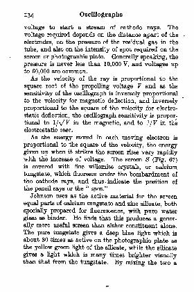
134 Oscillographs
voltage to start a stream of cathode rays. The
voltage required depends on the distance apart of the
electrodes, on the pressure of the residual gas in the
tube, and also on the intensity of spot required on the
screen or photographic plate. Generally speaking, the
pressure is never less than 10,000 V, and voltages upto 60,000 are common.As the velocity of the ray is proportional to the
square root of the propelling voltage V and as the
sensitivity of the oscillograph is inversely proportionalto the velocity for magnetic deflection, and inversely
proportional to the square of the velocity for electro-
static deflection, the oscillograph sensitivity is propor-tional to 1/VF in the magnetic, and to I/F in the
electrostatic case.
As the energy stored in each moving electron is
proportional to the square of the velocity, the energygiven up when it strikes the screen rises very rapidlywith the increase of voltage. The screen $ (Fig. 67)is covered with fine willemite crystals, or calcium
tungstate, which fluoresce under the bombardment of
the cathode rays, and thus > indicate the position of
the pencil rays or the"spot."
Johnson uses as the active material for the screen
equal parts of calcium tungstate and zinc silicate, both
specially prepared for fluorescence, with pure water
glass as binder. He finds that this produces a gener-
ally more useful screen than either constituent alone.
The pure tungstate gives a deep blue light which is
about 30 times as active on the photographic plate as
the yellow green light of the silicate, while the silicate
gives a light which is many times brighter visuallythan that from the tungstate. By mining the two a

The Cathode Ray Oscillograph 135
screen is produced more than half as bright visuallyas pure silicate and more than half as active photo-graphically as pure calcium tungstate.To increase the sensitivity of the oscillograph it is
necessary to have a means of obtaining a stream ofelectrons under a low voltage . Sir Joseph Thomson hasproposed a hot cathode of the same type as that usedby Coolidge in his X-ray tube to
produce free electrons. The cathodeis generally in the form of a flat spiralsurrounded by a cylindrical metallic
sheath as shown in Fig. 70. This
spiral can be made of tungsten or FIG. 70. SPIRAL
lime-coated platinum and is heated Fon HOT CATHODEY OsOtLLOQHAPH-,
. ., , , , ., ,
by passing a suitable current throughit. The magnitude of the heating current is determined
by the intensity of the cathode-anode stream, and the
temperature must be such as to cause a sufficient supplyof electrons for this stream. The object of the metallic
sheath surrounding the heated spiral is to preventspreading of the cathode stream as it leaves the spiraland to concentrate a larger portion of the stream onthe anode.
To obtain a fine spot on the screen it is necessary to
adjust the value of the current in the filament, the
voltage between the anode and cathode, and the
pressure of the residual gas in the tube.
The spot is much smaller and more intense if there is
a trace of gas left in the tube, a pressure of about
TOOT nim. of mercury being an average value. Thevalue of the vacuum must, however, be governed bythe appearance of the spot which should be very small,
bright, and without blurs or halos. If the tube be made

136 Oscillographs
throughout of glass and all the connections hermetic-
ally sealed through the glass there is no ready means of
altering the vacuum and, under working conditions,
there is a tendency for the gas pressure to diminish and
for. the spot to become larger. It is preferable there-
fore, whenever possible, to have a connection from the
tube to a suitable vacuum pump so that the vacuumcan be adjusted to give the best spot.
It is also necessary, as will be seen later, to have a
means of opening up the tube when it is desired to let
the spot produced by the cathode beam fall directly on
a photographic plate or film. In tHa case it is, of
course, necessary to re-evacuate the tube after it has
been opened to remove a record.
Alternative Forms ol Records. When using the
sealed-up tube such as shown in Fig. 67 there is no
convenient method of allowing a plate or film to passclose to the screen and in addition the actinic power of
the luminous spot is very small. It is necessary there-
fore, in order to obtain a record of the motion of the
spot, to have some means of causing a displacement of
the spot at right angles to the motion produced by the
electrostatic or magnetic field being studied.
Thus, if it were possible to use one pair of the
electrostatic plates to produce a field proportional to
voltage being studied, and if the second pair of plates
had a voltage applied to them which increased
uniformly with time, then the curve produced on the
screen would be a record of the voltage to be studied,
plotted to a uniform time base. Similarly, if a mag-netic field were arranged to produce a deflection of the
cathode beam at right angles to the deflection produced
by the voltage being studied, the record would be drawn

The Cathode Ray Oscillograph 137
to a uniform time base if the magnetic field increased
uniformly with. time.
When one is dealing with records from low frequency
sources, say from a machine, it is quite easy to arrangea potentiometer to revolve synchronously with the
wave to be examined and to supply either a current or
a pressure varying uniformly with time. If the spot
goes over the record time after time it produces a
steady image which can be viewed directly, or it can
be arranged to take a photograph of the trace by an
ordinary camera and, as long as the phenomenon beingstudied is constant, the record on the screen will be
constant and the photograph can be taken with a time
exposure to suit the intensity of the spot on the screen.
There are, however, many oases in which the frequency
is too high or where no potentiometer is available, and
it ia then necessary to obtain a means of recording the
curve.
In Fig. 67 when, say, an alternating potential is
applied between the plates P P, the spot will be dis-
placed up and down the screen as shown on the end
view of the screen at (a). If now the coils C C carry
a current of the same frequency as the supply to P Pthere will be a periodic displacement along the
horizontal axis. As it is more convenient to have this
periodic displacement simple harmonic motion, the
current in the coils CC should be made as nearly
sinusoidal as possible, and Fig. 71 shows an arrange-
ment by which this result can be obtained. In this
diagram P P represent the electrostatic plates of the
oscillograph, and CC the coils which produce the
horizontal displacement. A condenser _ a is placed
in parallel with C C to produce parallel resonance ;

Oscillographs
a condenser K^ is connected with a variable induc-
tance L to produce series resonance ; and a non-induc-
tive resistance J? a is connected in series with L and K lt
Then, when J2 a is small, the current in the series cir-
cuit is very nearly a pure sine wave owing to the high
impedance of L to all but the resonant frequency.This current is the resultant of the currents in. C C and
aa
FIG. 71. ABRANGHICBINT OF GEROUIT FOR OBTAININGSlNTJBOrDAI, CURSHNT IN COILS O O
KI and, as these are in resonance, the series current is
small compared with the current in C G and in JT B .
The current in C G is still more nearly sinusoidal
than the current in the series circuit since the impedanceof the condenser K^ varies inversely as the frequencyand the impedance of C C directly as the frequency,and so the higher the harmonic
,the greater the shunt-
ing effect of the condenser K z on the coils C 0.
When L and K^ are practically resonating, con-siderable changes in the phase of the currents can bemade by varying the value L.
The resistance .72 2 is placed in circuit to limit thevalue of the current until the circuits are adjusted.The coils C C produce a horizontal displacement
varying in simple harmonic motion, and the plates
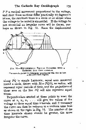
The Cathode Ray Oscillograph 139
P P a vertical movement proportional to the voltage,
and since these motions differ practically 90 degrees in
phase, the resultant trace is a circle or an ellipse whenthe voltage to be tested is sinusoidal. If the voltage "be
not sinusoidal an irregular curve will be drawn, per-
haps as shown in Pig. 72. Since the displacement
FIG. 72. HYPOTHETICAL RECORD OBTAINED WITH ACATHODE BAY OgomooQTtApH
Tlie curve IB plotted to rootanffulor oo-ordlnatee with time as baseIn the right-hand diagram
along PQ is simple harmonic, equal arcs measured
round a circle, drawn with R(= PQ/2], as radius, will
represent equal periods of tune, and the projections of
these arcs on the line PQ will also represent equal
times.
Perpendiculars erected at these points to meet the
curve at n^ n z n s ... will give the values of the
voltage at these equal time intervals, and if necessary
the curve can then be redrawn to a uniform time base
as shown on the right in Fig. 72. The number of the
time intervals chosen should be greater, the more
irregular the curve.

14 Oscillographs
In some oases the displacement of the ray in ahorizontal direction is not produced by a current or
voltage that is in any simple relation to the vertical
displacement, but as long as the horizontal displace-ment is in simple harmonic motion the record canalways be redrawn. In this case, however, since thecurve will not be retraced the exposure should pre-ferably be short so as to record only one traverse ofthe spot across the plate.
Improved Cathode Ray Oscillographs. While thecathode ray oscillograph, as devised by Braun, openeplup new fields of usefulness where oscillographs opera-ting with mechanical systems even as light as astretched wire would be inoperative, it is no doubt*due to the valuable work of Pufour that the cathoderay oscillograph occupies its present unique position.As already mentioned, Dufour has, by means of
improved technique and very elaborate apparatus,obtained photographic records of frequencies as highas 220,000,000 per sec. with a single trace, whereas afew years ago records of a million per sec. under suchconditions would have been considered wonderful.This great improvement has been due to his recogni-tion of the fact that, to work at high frequencies andobtain photographic records with a single trace overthe plate, it is necessary that : (1) the cathode rayshould fall directly on the plate ; (2) there should bea small amount of residual gas in the tube, (for thereason explained on p. 165) ; (3) at the extremelyhigh frequencies it is necessary to accelerate thecathode stream by a very high voltage even up to60,000 V.
^
Once it is recognized that the problem must be

The Cathode Ray Oscillograph 141
faced of opening the tube to admit or withdraw a
photographic plate, great modifications of Braun's
original model become desirable.
As a pump must be provided capable of producinga high vacuum it is no longer necessary to have the
joints in the apparatus hermetically sealed but a
ground-in metal to metal joint sealed with grease is
allowable, and it is possible to use metal instead of
glass for a great portion of the"tube."
The Dnfour Cathode Ray Oscillograph. Pig. 73
sh,ows the cathode oscillograph as developed by Dufour.The lower portion of the apparatus is metallic andserves to contain the phosphorescent screen and the
photographic apparatus. The part v is the inter-
mediate portion of the apparatus and is where theelectrostatic plates or the magnetic field is applied to
the cathode stream. The upper portion, d, is the
tube proper and contains at the upper end the cathodee and at the lower end a fine pin-hole tube / whichacts as the anode and is connected to the metallic bell
a forming the lower portion of the apparatus. The
air-tight door b gives admission to the lower portionof the "
tube," and allows the photographic plates andfilma to be taken in or out. The connection to the air
pump is made at m.
Both v and d are made of glass and are arranged to
fit into each and form an airtight joint. The tube v
also fits into a coned hole in a. The tube v could beof metal if it were only required for internal electro-
static deflecting plates, but not if it is required to use
it with external electrostatic plates or with a magneticfield. A conducting tube of any kind would be inad-
missible for external plates and would be inadmissible

H-
Fio. 73. THE DUB-DUB CATHODE RAY OSCILLOGRAPH
40 Rue de Seine, Paris ; franca).
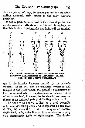
The Cathode Ray Oscillograph 143
at a frequency of, say, 50 oyoles per sec. for an alter-
nating magnetic field owing to the eddy currents
produced.When a glass tube is used with external plates the
results are not so reliable as with internal plates, because
the distribution of potential is not definite if the residual
E
Fio. 74. ALTBBWATIVE FOBMB ox TUBHB TO SUITDlFFHBHNT ABBANOBIOINTB OP DBFLBIOTINO PLATBS,
BTo., TS THU DDTOTJB OSOTLLOGBAPH
gas in the interior becomes ionized by the cathode
stream. There will also be dielectric hysteresis and
fatigue in the glass which will produce a distortion of
the curve and also a displacement of phase. It is
often convenient, however, to be able to use external
plates or an external pair of deflecting coils at will.
The tube v as shown in Fig. 73 is used normally
only with deflecting coils, and is replaced by the tube
G (Fig. 74) when it is required to employ an electro-
static field, or by tube D when it is required to employtwo electrostatic fields at right angles. The double
144 Oscillographs
tubes E, F, and G are arranged to enable simultaneousrecords to be obtained of two currents, or of a pressureand a current or of two pressures. The rays have to bemade parallel to each by small electro-magnets operatingwhere the two branches join the main tube.
In Fig. 73 is shown the arrangement Dufour employsto turn the photographic drum inside the vessel a.
An internal shaft n> which can engage the drum gby means of the crank I, is driven through a positivemagnetic clutch p from the outside shaft q. The linesof force from the magnet pass through a thin glasscap c which fits on to the extension of the vessel a.
The linear speed of the film on the drum can be madesome 500 cm. per sec. and this is the arrangement used'
up to frequencies of the order of 8000, but for the
higher of these frequencies their presence only is
indicated and not their exact shape.Dufour also has a high tension switch arranged to
operate synchronously with the rotation of the outsideshaft q. This is arranged to insure that the cathoderay will only be in action during one revolution of thedrum, thus preventing fogging of the plates.
Pig. 75 shows a record obtained in this way, and isa trace of the current in the primary of an inductioncoil working in conjunction with a Wehnelt break.When records of very high frequencies have to be
obtained the speed of the drum 'is relatively so slowthat no advantage is obtained by its use
; plates aretherefore used instead. It is then necessary to employan auxiliary high frequency sinusoidal current, notnecessarily or desirably of such high frequency as thesource being investigated. This auxiliary currentcauses the cathode spot to traverse the plate on one
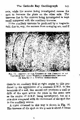
The Cathode Ray Oscillograph 145
axis, while the source being investigated causes the
spot to traverse the plate on the other axis. The
traverse due to the current being investigated is keptsmall compared with the auxiliary traverse.
If the auxiliary traverse be produced by a magneticfield due to, say, the current from a flinging arc, and if
FIG. 76. RECORD ov THE OtraBHNT IN THE PTCTMABY or ANINDUCTION COIL (WITH WHHNBHIT INTHRBTJPTBB) OBTAINED
BY MEANS or A DUTOUB OSCHLLOGBAPH
there be .an auxiliary field at right angles to this pro-
duced by the application of a constant E.M.F. to the
terminals of a ooil, this second coil produces a trail or
drift of the spot across the plate in the same axis
as the source of E.M.F. being investigated, but at a
rate slow compared with the movement of the spot due
to the auxiliary source.
A curve obtained in this way is shown in Fig. 76.
The traverse of the spot on the y axis is about 5 times

146 Oscillographs
as great as the traverse in the x axis, and the drift onthe x axis during a complete cycle of the auxiliaryfield is about equal to the traverse of the source beinginvestigated.
FIG. 76. RBOOBD OB- PBDSSTTRH VABIA.TIONS JN A SINGINGABO OBTAHTBD WITH A DTJFOTJB, OSOILLOGBAPH
This particular record (Fig. 76) is of the pressurevariations of a singing arc. The auxiliary oscilla-tions in the axis y are of a frequency of 10,000 per see.,the main oscillations in the a; axis are of a frequencyof about 240,000 per sec., and the high frequencyoscillations superimposed on the main oscillations areof the order of 6,000,000 per sec.

The Cathode Ray Oscillograph 147
It is sufficient to say that Dufour lias achieved., as
already mentioned, records up to a frequency of
220,000,000 per sec.3 but the records of these fre-
quencies do not lend themselves so well for reproduc-tion purposes. At such extreme frequencies the spotproduced on the plate by the cathode ray moves at arate of 800 to 900 kilometres per sec.
Hot Cathode Ray Oscillographs. Some crystals,such as tourmaline, have the property of giving anelectric charge or quantity of electricity when sub-
jected to mechanical pressure between two faces.
This charge changes in sign when the pressure becomes
^negative, i.e. for a suction. The rise in electrical
pressure due to the charge will, of course, depend onthe capacity of the apparatus connected to the crystal
and, as long as the capacity of the apparatus remains
constant, the rise of electrical pressure is proportionalto the rise of mechanical pressure.
This piezo electric effect gives a very valuable aid
to the study of extremely high and rapidly varyingmechanical pressures, and it has been so used by Sir
Joseph Thomson, in conjunction with the cathode ray
oscillograph, to study the rapid rise of pressure pro-
duced by explosions. To make the oscillograph more
sensitive and to accelerate the electrons with a smaller
voltage, Thomson used the hot cathode as already
described. Dr. Keys, who collaborated with him,
obtained in this way records of the pressure waves
produced in water by the detonation of charges of
gunootton and T.N.T.
The hot-cathode oscillograph as devised by Thomson
and Keys waa improved further in detail by Dr. A. B.
Wood and it will be sufficient to illustrate the later
148 Oscillographs
instrument as representative of its class. Fig. 77 is a
cross section showing the construction of the oscillo-
graph designed by Dr. Wood and is self-explanatory to
a large extent. It is a cathode ray oscillograph whichhas to be opened up to withdraw and insert the photo-
graphic plates and therefore is used in conjunctionwith an air pump. Near the top is a glass bulb con-
taining both the cathode and the anode, which are
comparatively close together as the instrument is
designed for a working pressure of about 3000 V.
The electro-magnet, the poles of which embrace the
tube, is used to produce the time-displacement of the
cathode spot on the plate. This magnet is not usedfor the measurement of the electric current flowingas the eddy currents and hysteresis in the iron wouldintroduce uncertainty, and so would the eddy currents
in the brass tube itself. The measurements made are
those due to the electrostatic forces and two pairs of
plates at right angles are shown.The records are obtained on photographic plates
mounted on the six sides of the hexagonal plate holder
shown at the bottom of the apparatus. This plateholder can be removed from the oscillograph when six
records have been made.The type of plate used is very important when one
is dealing with cathode rays operating under low
voltages, for the energy stored in the electron varies
directly as the voltage ; thus at a voltage of 3000 the
energy will be one-twentieth of that at 60,000 V. Toenable ordinary plates to be used successfully it is
necessary to sprinkle them with a t.Tn'nlayer of calcium
tungstate, but a better plan is to use Schumann plateswhich are specially prepared to have a minimum
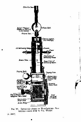
Ebonite
Spiral Fifament.-Tunfotcn or Ptutinun.
(Urn* CoetietJ
Drumcrryinf6 Plates.
FIG. 77. IMPBOVBD FOBM OF HOT-CATHODE RAYOSOTLLOGRAJH DTJH TO Da. WOODS
11 (5397)

150 Oscillographs
quantity of gelatine in the film. This type of plate
allows more of the electrons to impinge dirt^ptly on the
silver granules and, as a result, a speed of spot relative
to plate of 1000 metres per sec. is possible as comparedwith a speed of about 50 metres per sec. for ordinary
gelatine plates. This compares with a speed of 800,000
to 900,000 metres per sec. claimed by Dufour for his
oscillograph using a propelling pressure of 60,000 V.
It is evident therefore that if the results as regards
clearness and arrangement were comparable, increasing
the voltage twenty times would enable the relative
velocity of spot and plate to be increased some 800
times;
in other words as the voltage on theoscillo-^
graph is raised the photographic effects increase more
rapidly than the energy stored in the electron. This is
very fortunate as it enables records to be obtained
at very high frequency as long as the propelling voltageof the rays is high.
Characteristics of the Hot-Cathode Ray Oscillograph.
The first essential test that it is necessary to apply to
any oscillograph concerns its performance when a
sudden change of voltage is applied to it. The record
reproduced in Fig. 78(a) was obtained by suddenly
applying 40 V to the electrostatic plates of a hot-
cathode ray oscillograph when the spot was beingtrailed across the plate at a speed of about 5000 cm.
per sec. As far as one is able to judge the changefrom one value to the other is absolutely instantaneous
and there is no overshoot. Actually, there must be an
extremely slight rounding of the curve owing to the
finite speed of the electrons and there must be an
overshoot if the electrostatic plates are connected to
the source by leads having induction and comparatively

(a) Square wave test
(6) Frequency 18,000 per BOO.
(a) Frequency 46,000 per BBC.
FIG. 78. TYPIOAL RHOOHDS OBTAINED WITH A HOT-OATHODHOSOILLOGBAPH
152 Oscillographs
low resistance. The first effect is so small that it
would not appear, except at extremely high speed
of spot relative to plate, the second effect is shown
actually present in Fig. 76 given by Dufour.
It can be said, however, that even the slow speed
electrons produced by voltages as low as 100 V would
give records accurate up to frequencies as high as
1,000,000 per sec.
The curves shown in Pig. 78(6) and (c) are records of
frequencies of the order of 16,000 per sec. and 45,000
per sec. respectively. All the records in Pig. 78 were
kindly given the author, by Dr. Wood, and illustrate
very well the clearness of the records obtained.
To obtain the time-variation of the spot across the '
plate Dr. Wood generally uses the electro magnetmentioned above (see Pig. 77), and places in series
with it, a high inductance. If a constant B.M.P. be
applied to tTn'a circuit, the rate of change of current,
multiplied by the total self-induction of the circuit,
must be equal to the applied E.M.F. just at the moment
of switching on. It remains at approximately this
value for a time equal to, say, a quarter of the time-
constant of the circuit;
if therefore, LjR be made
large, the rate of change of current can be made con-
stant for an appreciable time, and the spot can be
trailed across the plate at a practically constant speed.
To increase the speed of the spot it is only necessary
to increase the applied E.M.P.
A similar result is attained if a condenser K be con-
neoted in parallel with one pair of electrostatic deflect-
ing plates and the combination be charged through a
resistance from a voltage V. The initial rate of rise
of the voltage across the plates is VjKR and, as it is
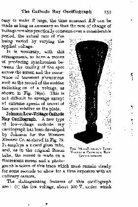
The Cathode Ray Oscillograph 153
easy to make R large, the time constant KR can bemade as long as necessary so that the rate of change of
voltage remains practically constant over a considerable
period, the actual rate of rise
being varied by varying the
applied voltage.It is necessary, with this
arrangement, to have a meansof producing synchronism be-
tween the trailing of the spotacross the screen and the occur-
rence of transient phenomenasuch as the record of the sudden
switching-en of a voltage, as
shown in Fig. 78(a). This is
not difficult to arrange exceptat extreme speeds of travel of
the spot relative to the plate.
Johnson Low-Voltage Cathode
Ray Oscillograph. A new typeof low-voltage cathode ray
oscillograph has been developed
by Johnson for the WesternElectric Co. as shown in Pig. 79.
It employs a closed glass tube,
and, as in the original Braun
tube, the record is made on a
fluorescent screen and a photo-
graph is taken of this trace which must remain steadyfor some seconds to allow for a tune exposure with an
ordinary camera.
The distinguishing features of this oscillographare : (1) the low voltage, about 300 V, under which
FIG. 79. JOHNSON Low-VOLTAGH CATHODB RAY
OSGTTiTiOCmAPH
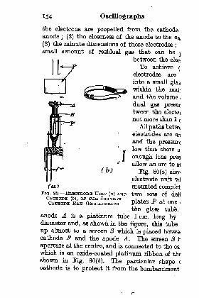
154 Oscillographs
the electrons are propelled from the cathodeanode
; (2) the closeness of the anode to the c
(3) the minute dimensions of these electrodes;
small amount of residual gas that can be
between the
To achieve
electrodes are
into a small
within the
and the volume ,
dual gas presettween the elects
not more than 1 (
All paths betweelectrodes are so
and the pressure
low that there a
enough ions prosallow an arc to B1
Fig. 80(o) ehoi
electrode unit w]
mounted complettwo sets of defj
plates P at one .
the glass tube,anode A is a platinum tube 1 cm. long bydiameter and, as shown in the figure, this tube
up almost to a screen 8 which is placed betwecathode F and the anode A. Hie screen S I
aperture at the centre, and is connected to the oawhich is an oxide-coated platinum ribbon of tht
shown in Fig. 80(6). The particular shape (
cathode is to protect it from the bombardment
I
(b)
(a)FIG. 80. FjTiBOTRODB UNIT (a) ANDCATHODE (6), ov THB JOHNSONCATHODE RAT OSCTLLOGBAPH
The Cathode Ray Oscillograph 155
ions (positive) which pass through the aperture in thescreen.
The cathode is heated by means of a current throughit, and serves to provide a supply of free electrons.
Those that pass near the aperture in the screen are
drawn through by the strong electrostatic field betweenthe anode and the screen, and are discharged in large
part down the anode tube. Those of the electrons
which have a flight along the axis of the tube emergeas a beam into the large tube and pass between thetwo pairs of plates.
The deflecting plates are of German silver to mini-
mize eddy currents when a magnetic field is employed"* to produce the deflection.
Focusing in Cathode Ray Oscillographs. As the
propelling voltage is low in the Johnson oscillograph,the velocity of the electrons is low compared with the
values considered in the earlier parts of this chapter.There is, therefore, time for the electrostatic repulsionbetween the electrons to cause dispersal, and this wouldbe serious except that it is possible to use the focusingdue to the presence of residual gas in the tube. Thelower the velocity of the electrons in the tube, the
greater the amount of residual gas required, and, in the
Johnson oscillograph a gas pressure of a few thousandthsof a millimetre of mercury is used.
The use of residual gas was suggested by Dr. H. J.
van der Bijl.
The focusing action of the residual gas can easilybe explained and the same explanation applies also
to the trace of gas left in the tube used by Dufour.
The number of electrons passing per sec. in a
beam between the deflecting plates of a cathode ray
156 Oscillographs
oscillograph varies with the current flowing between thelectrodes, and in the Johnson oscillograph it rnio-u-f-be some 1014 electrons. The velocity of the electrons isabout 10e cm. per sec., and therefore every centiinetrmeasured along the beam contains about 105
electronsin flight.
Initially, this number would be concentrated i^ abeam of about 1 Trim, diameter.
A number of these electrons in their flight -willimpinge on molecules of the residual gas and produceionization, i.e. the molecule is broken up and theelectron released. The release of the electron (carryingthe negative charge) from the neutral molecule leavesthe ion (carrying a positive charge), but the velocitiesof the original electron and of the displaced electronare high and they leave the path of the beam at avery high speed while the relatively heavy and slo\vion leaves the beam at a slow speed.
There will therefore be along the beam an excessof positive ions over negative ions, and this meansthat the rays are drawn in towards the axis of thebeam.At first sight it might appear strange that any con-
siderable percentage of the electrons could pass throughthe residual gas without coming into collision withthe molecules.
At a pressure of 0-001 mm. of mercury the numberof molecules present in the gas is still of the order of3 X 1018
per ou. cm., and if the length of path in theoscillograph be 30 cm., the number in the path of theray (assumed to be 1 sq. mm. in cross section) wouldbe roughly 1013 molecules. The area of the shadowsoast by the molecules (if one could assume a molecule
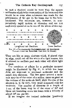
The Cathode Ray Oscillograph 157
to cast a shadow) would be more than the squaremillimetre which is the cross section of thebeam and this
would be so even when allowance was made for the
attenuation of the gas in the beam due to the bom-bardment: The molecules are, however, in com-
paratively rapid motion or vibration and are not
uniformly spaced so as to cut off the whole of the ray.
f --*-- O rKJ1
'O --O-i O--^-O
> <J (S) """"S^y."-'
Longitudinal Section. Cross Section.
FlG. 81. DlAOBAMMATIO REPBHSHNTATION OF ELECTRONSPASSING THHOUGH RABBWEED GAS (NOT TO SCALE)
They are like so many shutters which, if placed edgeto edge, could cut off the whole of a light source, but
if allowed to oscillate past each other will allow light
to pass.The condition of affairs for a particular moment
might be illustrated by Fig. 81, in which the large
dots are supposed to represent molecules and the
.small dots electrons. The free space around a mole-
cule may be of the order of a million times as great as
the volume of the molecule itself, while the size of the
electron is, in its turn, very small compared with the
molecule. The number of electrons in a length of
1 cm. of the beam may be of the order of 106 and
these are travelling down the beam with a velocity of
about 10B cm. per sec.
If we imagine the ionized molecules (positively
158 Oscillographs
charged) to be uniformly distributed down the beamand over its cross section then the resultant charge
1
oould.be represented, as far as its effect on other outside
charges is concerned, by concentrating this, charge along-the axis of the beam, i.e. at its centre of gravity. In a-
sirm'laj way, the force due to the uniformly distributed
electrons (negatively charged) could be considered tobe due to these electrons concentrated along the axis.
The force on any individual electron on the boundaryof the team is towards the axis or away from the axis,
depending on whether there is an excess of ions or ofelectrons.
For an electron inside the beam, at a distance Rffrom the axis, the force is Ra/JRm of that at the boundary,
r
and will act in the same direction as the force at the
boundary if the distribution of electrons and ions is-
uniform.
If the numbers of electrons and ions are equal, therewill be no force on the moving electrons, and the beamwill .only spread due to any initial divergence it mayhave. If the angle of divergence be known, then thenumber of free ions required per em. length to turnthe outside electrons and bring them to a focus at thescreen can be estimated.
In any case, increasing the current increases the total
ionization and the inward pull on the electrons and so
brings the beam more quickly to a focus.
A characteristic of this and indeed of all cathode
ray oscillographs is the conductivity between the
deflecting plates, due to the ionization of the residual
gas. This conductivity is not constant, but varies-
with the direction and magnitude of applied voltage ;
it is therefore not possible to use a series condenser to-

The Cathode Ray Oscillograph 139
reduce the voltage applied to the instrument as this
would produce appreciable distortion except when the
frequency was very high. The conductivity betweenthe plates depends on the number of free ions betweenthem and will therefore increase with the size of the
plates and their distance apart, provided that the
cathode ray has been passing in the tube for sometime before the deflecting voltage is applied to the
plates. It will also increase with the pressure of the
gas, if the cathode ray remain constant, as the numberof coUisiQiis between electrons and molecules will
increase, and so increase the number of free ions.
^ The current passing between the plates cannot t>e
greater than that required to carry the free negativeions to the positive plate and the free positive ions to the
negative plate as fast aa they are produced by the bom-bardment. The current will therefore not increase
proportionally to the voltage but, after a certain
voltage is reached, will remain constant. This cur-
rent is called the saturation current and will only start
to increase again when the voltage between the deflect-
ing plates is raised to such a point that it can produceionization on its own account.

BLONDEL .
BLONDEL .
DUDDKLL .
BIBLIOGRAPHYTELE references given below, though for from complete,relate to a number of important papers which should
be studied by those who wish to study in detail the
development of oscillographs and their applications.
La Lumiere Eledrique ; 1891 ; Vol.41, p. 401.
Comptes Rendua ; 1898; Vol. OXVI,pp. 502, 748.
Paper before British Association,Toronto, 1897 ; Electrician, Vol.
39, p. 636.
Bulletin de la Soc. int des Mectr. -
r
1897 ; Vol. 14, p. 897.
Wied. Ann ; 1897 ; Vol. 60, p. 562.E. T. Z.
; 1898 ; p. 204.
L'Eclairage Electrique, 28th Oct.,1902.
Jour. Inert, of Elect. Enga. \ 1907 ^
Vol. 39, p. 617.
Journal de Phys. ; 1909 ; Vol. 4 r
p. 266.
Electrician ; 1912 ; Vol. 69, p. 367.
Comptes Rendua ; 1914 ; Vol. 158,.
p. 1139.
Jour. Inat. of Elect. Engs. ; 1916 ^
Vol. 54, No. 251.
Engineering ; 1919 ; Vol. 107, pp,543, 544.
Jour. Amer.I.EJE., July, 1920.
Phya. Rev. (2) ; 1920; Vol. 17, p. 420.
Jour. Opt. Soc. of America ; 1922 ;
Vol. 0, p. 701.
Jour. Phya. Soo. (.London) ; 1923 ;
Vol. 35, Part 2.
Jour. Franklin Inat. ; 1923 ; VoL196, No. 5.
Oscillographie Cathodigue ; pamphletpublished by Etienne Chiron, 40>
Rue de Seine, Paris.
161
BRA.UN
BLONDEL .
IBWIN
ABBAHAM .
SOLOMONBONA. DOT-OUR
.
.
HOWE
THOMPSON (Sir J. J.)
LEGOJOHNSON .
JOHNSON .
WOOD
KEYS
DUPOUR

162 Oscillographs
The undermentioned Technical Primers (Pitman,2s. 6d. net) are likely to interest readers of this book.
First Principles of Electrical Transmission of Enerav. byW. M. Thornton.
Electrical Insulation, by W. 8. Flight.Electric Power Systems, by W. T. Taylor.Modem Central Stations, by 0. W. Marshall.
Switching and Switchgear, by H. E. Poole.
High Tension Sioitchgear, by H. E. Poole.
High Tension Switchboards, by H. E. Poole.Electric Cables, by F. W. Main.A.C. Protective Systems and Gear, by J. Henderson and
0. W. Marshall.
High Voltage Power Transformers, by W. T. Taylor.Small Single Phase Transformers, by E. T. Painton.Industrial Motor Control, D.C., by A. T. Dover.D.C. Traction Motor Control, by A. T. Dover. *Small Electric Motors, by E. T. Painton.
Testing Transformers and A.C. Machines, by 0. F. SmithTesting Continuous Current Machines, by 0. F. Smith.Industrial Electric Heating, by J. W. Beauchamp.Continuous Wave Wireless, by B. E. GK Mittell.Power Factor Correction, by A. E. Clayton.Industrial Applications of X-Rays, by P. H. S. Kempton.Directive Wireless Telegraphy, by L. H. Walter.Radioactivity, by J. Chadwiok.
Many other volumes are in preparation for theaeries of Technical Primers, full particulars of whichcan be obtained from the Publishers, at PitmanHouse, Parker Street, Kingsway, W.C.2.
3252
ABRAHAM rheograph,
Dr. H. J. van, ^residual gas in cathode rev
oscillographs, 155
Blondel, invention of oscillo-
graph, 1
, bifllar oscillograph, 30
, moving iron oscillograph,40
Braun, cathode ray oscillograph,126
CALCIUM tungst.ate for fluores-
cent screen, 134
^Capacity of electrostatic oscillo-
graphs, 71
, wire between parallel
plates,66
Carpentier oscillograph, 37Cathodes for ray oscillograph,
126, 135, 154Cathode ray oscillograph, 120
.sensitivity of, 130,132
Condenser, as shunt to series
resistance to extend range of
oscillographs, 107
, as shunt to series resist-
ance hot-wire oscillo-
graph, 44
, in series with electrostatic
oscillograph, 71
, inadmissible in series withcathode ray oscillograph,159
, to calibrate electrostatic
wattmeter, 70
, use with rheograph, 53, 58
, time to charge, 73Correction of oscillograph
records, 35, 38
DAMPING of oscillographs
by air, 28, 29
by oil, 32, 35, 60
.stance,
by resonant shunt,29, 91, 104
force, relation to con-trol and inertia
forces, 12Duddell development of oscillo-
graph, 1
oscillograph, 32
Dufour, cathode ray oscillo-
graphs, 141tubes used with cathode
ray oscillographs, 143
EINTHOVHN oscillograph, 23
, optical arrangementof, 24
sensitivity,26
, change of sensitivitywith change of
length, 27
electrostatic, 64Electrostatic oscillographs, 59
Electro-magnetic oscillographs,23, 30, 38
FLUOBJBSOBTNT screen, 126, 134Forces on current-carrying wire
in magnetic field, 5-15on charged wire in electric
field, 87Force OQ electric charge moving
in magnetic field, 127 [128in electric field,
on stretched diaphragm in
electric field, 64
inertia, magnitude of, 13
damping, magnitude of, 1 5
Frequency oi vibration of
stretched wire, 18of loaded and stretch-
ed wire, 20-22stretched diaphragm,
63
163

164 Index
60
GBNKRAL ELECTBIO Co. oscil-
lograph 38, 124
Gray electrostatic oscillograph,59
HODGSON proof of resonantshunt method, 100, 114
Ho and Kato electrostatic
oscillograph, 70Hot-wire oscillograph, 42
electrostatic oscillograph,
hot-wire oscillograph, 42- method of damping byresonant shunt, 91
JOHNSON low-voltage cathoderay oscillograph, 153
KATO, and Ho ; electrostatic
oscillograph, 70
Keys, use of hot-cathode rayoscillograph to record explo-sion s, 147
LAG of deflection behind appliedforce, oil damping, 86, 87
Lag of deflection behind appliedforce, resonant shunt dampinc.99
Lag of deflection behind appliedforce, with resonant shuntdamping and with the seriesresistance shunted by a con-denser, 110
MAGNIFICATION of deflectionwith and without damping, 81-
plotted against change of
frequency, 83, 87-expression for, with ordin-
ary damping, 84-- expression for, with reson-ant shunt, 96- when series
shunted by108
OPTICAL arr _oscillographs
Optical arrangements of stringoscillographs, 24
Oil, change of viscosity due to-
temperature change, 35, 123
POWBH, measurements with elec-trostatic oscillograph, 72
records with electrostatic
oscillograph, 78, 79
RESISTANCE, series, with hot-wire and electrostatic for
damping purposes, 50, 73Reeonance, effect on harmonics
77Resonant shunt, 91
Rheograph, Abraham, 51
SATURATION current in cathoderay oscillographs, 169
Schumann, photographic plates*for cathode ray oscilloscraDh148
of,Siemens and Halske oscillograph,
Singing Arc, record of, 146Shunt resonant, dampinjr bv
104y '
for current measurementsby hot-wire oscillograph,48 f6 sf
by rheograph,Speed of spot in cathode ray
oscillograph relative to photo-graphic plate, 147, 160
THOMSON, Sir Joseph, hot-cathode ray oscillograph, 135
Transformer, quadrature forhob-wire oscillograph, 47
;
for rheograph, 64, high tension, records of, 76
WBHNHLT-break, record of withiy oscillograph, 145
lillograph, 38Is, use for
uoresoent
AN ABRIDGED LIST OF
TECHNICAL BOOKSPUBLISHED BY
Sir Isaac Pitman& Sons,Ltd.(Incorporating WHITTAKER * CO.)
PARKER STREET, KINGSWAY,LONDON, W.C.2
The prices given apply only to the British Isles, and are
subject to alteration without notice.
A complete Catalogue giving fun detaflfl ol the following
books wfll be sent post free on application.
ALL PRICES ARE NET.s. d.
ACCUMULATORS, MANAGEMENT OF. Sir D. Salomons 7 8
AEROFOILS AND RESISTANCE OF AERODYNAMICBODIES. PROPERTIES OF. A. W. Judge . . 18
AERONAUTICS, ELEMENTARY. A. P. Thuiston . 8 6
AERONAUTICAL ENGINEERING, TEXTBOOK OF. A.
Klemin 15
AEROPLANE DESIGN AND CONSTRUCTION,ELEMENTARY PRINCIPLES OF. A. W. Judge . 7 6
AEROPLANES, DESIGN OF. A. W. Judge . . 14
AEROPLANE STRUCTURAL DESIGN. T. H. Jonesand J. D. Filer 2t
AIRCRAFT AND AUTOMOBILE MATERIALS FERROUS,A. W. Judge 25
AIRCRAFT AND AUTOMOBILE MATERIALS NON-FERROUS AND ORGANIC. A. W. Judge . . 25
AIRSHIP, THE RIGID. E. H. Lewitt . . 30
ALTERNATING CURRENT BRIDGE METHODS OFELECTRICAL MEASUREMENT. B. Hague . . 15
ALTERNATING-CURRENT CIRCUIT, THE. P. Kemp. 2 6
ALTERNATING CURRENT MACHINERY, DESIGN OF.
J. R. Barr and R. D. Archibald . . . 30
ALTERNATING CURRENT MACHINERY, PAPERS ONTHE DESIGN or. C. C. Hawkins, S. P. Smith, andS. Neville 21
ALTERNATING-CURRENT WORK. W. Perren Maycock 10 6
B5 5
. d.
ARCHITECTURAL HYGIENE. B. F. and H. P. Fletcher 10 6ARITHMETIC OF ALTERNATING CURRENTS. E. H.dapper 46
ARITHMETIC OF ELECTRICAL ENGINEERING. Whit-taker's 36
ARITHMETIC OF TELEGRAPHY AND TELEPHONY.T. E. Herbert and R. G. de Wardt . . .50
ARMATURE WINDING, PRACTICAL DDXECT-CURRENT.L. Wollison 76
ARTIFICIAL SILK AND ITS MANUFACTURE. J.Foltzer. Translated by S. Woodhonse . . 21
AUTOMOBILE AND AIRCRAFT ENGINES. A. W. Judge 30AUTOMOBILE ENGINEERS, REPORT OF THE INSTI-TUTE OF, ON FUELS . . ... .106
AUTOMOBILE IGNITION AND VALVE TIMING, START-ING, AND LIGHTING. J. B. Rathbnn . .80
BALLAND ROLLER BEARINGS, HANDBOOK OF. A. W.Macaulay . . . . . . . 12 6
BAUDOT PRINTING TELEGRAPH SYSTEM. H. W.Pendry ..60
BLASTING WITH HIGH EXPLOSIVES. W. G.Boulton . . . . . . .50
BLUB PRINTING AND MODERN PLAN COPYING.B. J. Hall 60
BLUE PRINT READING. J. Brahdy . . . 10 6BREWING AND MALTING. J. Rosa Mackenzie . 8 6B.S.A., BOOK OF THE 20CABINET MAKING, ART AND CRAFT OF. D. Denning 7 6CALCULUS FOR ENGINEERING STUDENTS. J. Stoney 3 6CAMERA LENSES. A. W. Lockett . . .26CARBURETTOR HANDBOOK. E. W. Knott . . 10 6CARPENTRY AND JOINERY. B. F. and H. P. Fletcher 10 6CERAMIC INDUSTRIES POCKET BOOK. A. B. Searle 8 6CHEMICAL ENGINEERING, INTRODUCTION TO. A. F.
Allen 10 6CHEMISTRY, A FIRST BOOK OF. A Conlthard . 3CLUTCHES, FRICTION. R. Waring-Brown . .50COLLIERY ELECTRICAL ENGINEERING. G.M.Harvey 15COLOUR IN WOVEN DESIGN: A TREATISE ONTEXTILE COLOURING. R. Beaumont . . 21
COMPRESSED AIR POWER. A. W. and Z. W. Daw 21CONTINUOUS-CURRENT DYNAMO DESIGN, ELEMEN-TARY PRINCIPLES OF. H. M. Hobart . 10 6
CONTINUOUS CURRENT MOTORS AND CONTROL AP-PARATUS. W. Perron Maycock , , ,76
*. d.
COSTING ORGANIZATION FOR ENGINEERS. E. W.Workman . . . .36
COTTON-SPINNERS' POCKET BOOK, THE. J.F. Innes 3 6
DETAIL DESIGN OF MARINE SCREW PROPELLERS.D. H. Jackson 60
DIRECT CURRENT DYNAMO AND MOTOR FAULTS.R. M. Archer 76
DIRECT CURRENT ELECTRICAL ENGINEERING. J. R.Barr 15
DIRECT CURRENT ELECTRICAL ENGINEERING, THEELEMENTS OF. H. F. Trewman and G. E.
CondlLSe 50DRAWING AND DESIGNING. C. G. Leland . ,36DRAWING. MANUAL INSTRUCTION. S. Barter . 4
DRAWING OFFICE PRACTICE. H. P. Ward . .76DRESS, BLOUSE, AND COSTUME CLOTHS, DESIGNAND FABRICMANUFACTURE OF. R. Beaumont . 42
DYNAMO, How TO MANAGE THE. A. E. Bottone 2
DYNAMO : ITS THEORY, DESIGN, AND MANUFACTURE,THE. C. C. Hawkins. Vol. I . . . 21
Vol. II 15
ELECTRIC BELLS. S. R. Bottone . . .36ELECTRIC CIRCUIT THEORY AND CALCULATIONS.W. Perron Maycock 10 6
ELECTRIC GUIDES, HAWKINS'. 10 volumes, each 5
ELECTRIC LIGHTING AND POWER DISTRIBUTION.Vol. I. W. Perron Maycock . . . . 10 6
Vol. II 10 6
ELECTRIC LIGHTING IN THE HOME. L, Gaater . 6
ELECTRIC LIGHTING IN FACTORIES. L. Caster and
J. S. Dow 6
ELECTRIC LIGHT FITTING : A TREATISE ON WIRINGFOR LIGHTING, HEATING, &c. S. C. Batstone . 6
ELECTRIC LIGHT FITTING, PRACTICAL. F. C Allaop . 7 6
ELECTRIC MINING MACHINERY. S. F. Walker . 15
ELECTRIC MOTORS AND CONTROL SYSTEMS. A. T.
Dover . . . . . . . . 15ELECTRICMOTORS DIRECT CURRENT. H.M. Hobart 15
ELECTRIC MOTORS POLYPHASE. H. M. Hobart 15
ELECTRIC MOTORS, A SMALL BOOK ON. C.C. ANDA.C. W. Perren Maycock . . . .60
ELECTRIC TRACTION. A. T. Dover . . . 21
ELECTRIC WIRING, FITTINGS, SWITCHES, AND LAMPS.W. Perren Maycock 10 6
ELECTRIC WIRING DIAGRAMS. W. Perren Maycock 5
ELECTRIC WIRING TABLES. W. Perren Maycock . 3 6
s. d.
ELECTRICAL ENGINEERS' POCKET BOOK. Whit-taker's 10 6
ELECTRICAL INSTRUMENT MAKING TOR AMATEURS.5. R. Bottone 60
ELECTRICAL INSTRUMENTS IN THEORY AND PRAC-TICE. Murdoch and Oschwald . . . 12 6
ELECTRICAL MACHINES, PRACTICAL TESTING OP.L. Onlton and N. J. Wilson . . . .60
ELECTRICAL POWER ENGINEERS' LIBRARY. Threevolumes, each 7s. 6d. ; Complete set . . 20
ELECTRICAL TECHNOLOGY. H. Cotton . . 12 6ELECTRICAL TERMS, DICTIONARY OF. S. R.
Roget 76ELECTRICAL TRANSMISSION OF PHOTOGRAPHS. M. J.Martin 60
ELECTRICITY. R. E. Neale . . . .30ELECTRICITY AND MAGNETISM, FIRST BOOK OF. W.
Perron Maycock . . . . . .60ELECTRO MOTORS : How MADE AND How USED.
S. R. Bottone 46ELECTROLYTIC RECTIFIERS. N. A. de BRUYNE . 3 6ELECTRO-PLATERS' HANDBOOK. G. E. Bonney . 5
ELECTRO-TECHNICS, ELEMENTS OF. A. P. Young SENGINEER DRAUGHTSMEN'S WORK : HINTS TO BB-GINNBRS IN DRAWING OFFICES . . .26
ENGINEERING SCIENCE, PRIMER OF. E. S. Andrews.Part 1, 2s. 6d. ; Part 2, 2s. ; Complete .36
ENGINEERING WORKSHOP EXERCISES. E. Pull . 3 6ENGINEERS' AND ERECTORS' POCKET DICTIONARY :
ENGLISH, GERMAN, DUTCH. W. H. Steenbeek 2 6ENGLISH FOR TECHNICAL STUDENTS. F. F. Potter 2FIELD MANUAL OF SURVEY METHODS AND OPERA-
TIONS. A. Lovat Higgins . . . . 21FIELD WORK FOR SCHOOLS. E. H. Harrison and
C. A. Hunter 20FILES AND FILING. Fremont and Taylor . . 21FITTING, PRINCIPLES OF. J. G. Homer . .76FIVE FIGURE LOGARITHMS. W. E. Dommett . 1 6FLAX CULTURE AND PREPARATION. F. Bradbury 10 6FUEL ECONOMY IN STEAM PLANTS. A. Grounds . 5FUEL OILS AND THEIR APPLICATIONS. H. V.
Mitchell . ...... 5FUELS. REPORT OF THE INSTITUTE OF AUTOMOBILEENGINEERS ON 10 6
FUSELAGE DESIGN. A. W. Judge . . .30GAS, GASOLINE, AMD On. ENGINES. J. B. Rathbun 8

f. d.
GAS ENGINE TROUBLES AND INSTALLATIONS. J. B.
Rathbnn 80GAB AND On. ENGINE OPERATION. J. Okill . 5 o
GAB, On, AND PETROL ENGINES : INCLUDINGSUCTION GAB PLANT AND HUMPHREY PUMPS.
A. Garrard 60GEOMETRY, THE ELEMENTS OF PRACTICAL PLANE.
P. W. Scott *
GEOLOGY, ELEMENTARY. A. J. Jukes-Browne . 3
GRAPHIC STATICS, ELEMENTARY. J. T. Wight . 5
HANDRAILING FOR GEOMETRICAL STAIRCASES.
W. A. Scott 26HIGH HEAVENS, IN THE. Sir R. Ball . .50HIGHWAY ENGINEER'S YEAR BOOK. H. G. Whyatt. 6
HOSIERY MANUFACTURE. W. Davis . . .76HYDRAULICS. E. H. LEWITT . . . .86ILLUMINANTS AND ILLUMINATING ENGINEERING,MODERN. Dow and Caster . . . . 25
INDICATOR HANDBOOK. C. N. Pickworth . .76INDUCTION QMLB. G. E. Bonney . . .60INDUCTION COIL, THEORY OF THE. E. Taylor-Jones 12 6
IONIC VALVE, GUIDE TO STUDY OF THE. W. D.
Owen 26IRONFOUNDING, PRACTICAL J. G. Homer . . 10
IRON, STEEL AND METAL TRADES, TABLES FOR THE.
J. Steel 36KlNEMATOGRAPHY (PROJECTION), GUIDE TO. C. N.
Bennett 10 6
LACguER WORK. G. Koizumi . . . . 15
LEATHER WORK. C. G. Leland . . .50LEKTRIK LIGHTING CONNECTIONS. W. Perren
Maycock . . . . .10LENS WORK FOR AMATEURS. H. Orford . .36LIGHTNING CONDUCTORS AND LIGHTNING GUARDS.
Sir O. Lodge 15
LOGARITHMS FOR BEGINNERS. C. N. Pickworth . 1 6
Low TEMPERATURE DISTILLATION. S. North .15MACHINE DESIGN. G. W. Bird . . .60MACHINE DRAWING, PREPARATORY Counaa TO.
P. W. Scott 20MAGNETISM AND ELECTRICITY, AN INTRODUCTORYCOURSE OF PRACTICAL. J. R. Ashworth . 3
MAGNETO AND ELECTRIC IGNITION. W. Hibbert . 3 6
MANURING LAND, TABLES FOR MEASURING AND,
J. CiJlyer 30

. .
MARINE ENGINEERS, PRACTICAL ADVICE FOR.C. W. Roberts . . . . .50
MARINE SCREW PROPELLERS. DETAIL DESIGN OF.D. H. Jackson 60
MATHEMATICAL TABLES. W. E. Dommett . .46MATHEMATICS, ENGINEERING APPLICATIONS OF. W.
C. Bickley 50MATHEMATICS, MINING (PRELIMINARY). G. W.
Stringiellow. With Answers . . . .20MECHANICAL ENGINEERING DETAIL TABLES. J. P.Ross . . , 76
MECHANICAL ENGINEERS' POCKET BOOK. Whit-taker's 12 6
MECHANICAL REFRIGERATION. H. Williams . 20MECHANICAL STOKING. D. Brownlie . .50MECHANICAL TABLES . . . . .20MECHANICS' AND DRAUGHTSMEN'S POCKET BOOK.W. E. Dommett .26
METAL TURNING. J. G. Homer . . .60METAL WORK, PRACTICAL SHEET AND PLATE. E. A,
Atkins . . . . . . . .76METAL WORK REPOUSSE. C. G. Leland . ! 5METALWORKERS' PRACTICAL CALCULATOR. J.Matheson . . . . . . .20
METRIC AND BRITISH SYSTEMS. OF WEIGHTS ANDMEASURES. F. M. Perkta . . . .36
METRIC CONVERSION TABLES. W. E. Dommett .2 8MILLING, MODERN. E. Pull . . . .90MINERALOGY. F. H. Hatch . . . '.60MININO, MODERN PRACTICE OF COAL. Kerr and
Burns. Part 1, 5/- ; Parts 2, 3 and 4, each . 6MINING SCIENCE, JUNIOR COURSE IN. H. G. Bishop 2 6MOTION PICTURE OPERATION, STAGE ELECTRICS.
ETC. H. C. Horstmann and V. H. Tousley . 7 6MOTOR TRUCK AND AUTOMOBILM MOTORS ANDMECHANISM. T. H, Russell . . . .80
MOTOR BOATS, HYDROPLANES AND HYDROAERO-PLANES. T, H. Russell 80
Music JINGRAVING AND PRINTING. W. Gamble .21NAVAL DICTIONARY, ITALIAN-ENGLISH AND
ENGLISH-ITALIAN. W. T. Davis . . . 10 6OPTICS OP PHOTOGRAPHY AND PHOTOGRAPHICLENSES. J. T. Taylor 40
PATENTS FOR INVENTIONS. J. E. Walker andR. B. Foster
. 21PATTERK-MARTNO, PRINCIPLES OF. J. G. Homer 4

. d,
PLAN COPYING IN BLACK LINES FOR HOT CLIMATESB. J.Hall 26
PLYWOOD AND GLUE, MANUFACTURE AND USE OFTHE. B. C. Bonlton .... 76
POLYPHARB CURRENTS, A. Still . . 7 ePOWER STATION EFFICIENCY CONTROL. J. Brace 12 6POWER WIRING DIAGRAMS. A. T. Dover . 6PRINTING. H. A. Maddoi . . . . 50QUANTITIES AND QUANTITY TAKING. W. E. Davii 6
RADIO COMMUNICATION, MODERN. J. H. Reyner 5
RADIO YEAR BOOK . . . . . .16RAILWAY ELECTRIFICATION. H. F. Trewman . 25RAILWAY TECHNICAL VOCABULARY. L. Serraillier 7 6RALEIGH HANDBOOK, THE. Mentor . . .20REFRACTORIES FOR FURNACES, CRUCIBLES, ETC.
A. B. Searle 50REINFORCED CONCRETE. W. N. Twelvetrees . 21REINFORCED CONCRETE BEAMS AND COLUMNS,PRACTICAL DESIGN OF. W. N. Twelvetrees . 7 8
REINFORCED CONCRETE MEMBERS, SIMPLIFIEDMETHODS OF CALCULATING. W. N. Twelvetrees 5
REINFORCED CONCRETE, DETAIL DESIGN IN.
E. S. Andrews . . . . . .60ROSES AND ROSE GROWING. R, G. Kingaley . 7 6RUSSIAN WEIGHTS AND MEASURES, TABLES OF.
Redvers Elder 26SHOT-GUNS. H. B. C. Pollard . . . .60SLIDE RULE. A. L. Higgins .... 6SLIDE RULE. C. N. Pickworth . . .36Son-, SCIENCE OF THE. C. WarreH . . .36STEAM TURBINE THEORY AND PRACTICE. W. J.
Kearton : . . . . . . 15STEAM TURBO-ALTERNATOR, THE. L. C. Grant . 15 n
STEELS, SPECIAL. T. H. Burnham . . .50STEEL WORKS ANALYSIS. J. O. Arnold and F.Tbbotson 12 6
STORAGE BATTBHY PRACTICE. R. Ranldn . .76SURVEYING AND SURVEYING INSTRUMENTS. G. A.
T. Middleton 60SURVEYING, TUTORIAL LAND AND MINE. T. Bryson 1 fi
TELEGRAPHY. T. E. Herbert . . . .180TELEGRAPHY, ELEMENTARY. H. W. Pendry . 7 6TELEPHONE HANDBOOK, PRACTICAL. J. Poole .15TELEPHONES, AUTOMATIC. F. A. Ellaon . .50

TELEPHONY. T. E. Herbert . .
TEXTILE CALCULATIONS. G. H. Whitwam .
TRANSFORMER PRACTICE, THE ESSENTIALS OF*E. G. Reed . . ...
TRIGONOMETRY FOR ENGINEERS, PRIMER OF. W. G!Dunkley . .
TURRET LATHE TOOLS, How TO LAY Our .'
UNION TEXTILE FABRICATION. R. BeaumontVENTILATION, PUMPING, AND HAULAGE THEMATHEMATICS OF. F. Bixks . ...
VOLUMETRIC ANALYSIS. J. B. CoppockWATER MAINS,. THE LAY-OUT OF SMALL. H. HHeUinB.....
WATERWORKS FOR URBAN AND RURAL DISTRICTSH. C. Adams.....
WEAVING FOR BEGINNERS. L, HooperW?f
v5LG WITH SMA"- APPLIANCES. L. Hooper(1) THE WEAVING BOARD. (2) TABLET WEAV-ING. (3) TABLE LOOM WEAVING. Each
WELDING, ELECTRIC. L. B. Wilson .
WELDING. ELECTRIC ARC AND OXYACBTYLBNBE. A. Atkins .
WIRELESS POCKET BOOK, MARINE! W. H. MarchaiitWIRELESS TELEGRAPHY AND TELEPHONY AnINTRODUCTION TO. J. A. Fleming .
WIRELESS TELEGRAPHY. W. IL Marchant'WOOD-BLOCK PRINTING. F. Morley FletcherWOODCARVING. C. G. LelandWOODWORK. MANUAL INSTRUCTION. S. BarterWOOLLEN YARN PRODUCTION. T. LawsonWOOL SUBSTITUTES. R. BeaumontWORKSHOP GAUGES. L. Burn and ft F F' Eagar
s. d"
1825
12 6
56
21
5
3 6
7 6
15'S
7 65
7 66
3 67 *8 67 67 a
3 610 65
Complete Ducriptioe Catalogae of Scientific andTechnical Bookt post free.
LONDON: SIR ISAAC PITMAN & SONS. LTDPARKER STREET, KTNGSWAY, W.C.2'
