- ge fanuc | ge plc€¦ · the ge fanuc series 90-30 plc system has the largest installed base of...
TRANSCRIPT
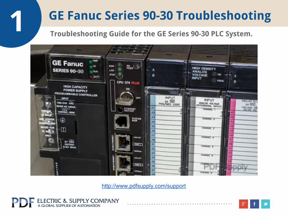
1 GE Fanuc Series 90-30 Troubleshooting
www.pdfsupply.com/support
Troubleshooting Guide for the GE Series 90-30 PLC System.
http://www.pdfsupply.com/support

TABLE OF CONTENTS
Introduction // 3
Step 1 - Power Supply Status // 4
Step 2 - CPU Power-Up Status // 5
Step 3 - CPU Run Status // 6
Step 4 - Battery Status // 7
Step 5 - CPU Out Of Run Mode // 8
Step 6 - View Fault Tables // 9
Step 7 - Additional Support Options // 10

3 Introduction - 90-30 Troubleshooting
The GE Fanuc Series 90-30 PLC System has the largest installed base of all GE PLC’s, therefore we felt it was important to assist users with some troubleshooting
procedures.
Our 33 years of expertise allows us to provide a concise process for identifying problems, as well as procedures
which will help you recover from a factory-down situation.
There’s an old saying – “If you don’t know where you’re going, then any road will take you there.”
This guide will help you identify the PLC problems, and then systematically provide you with practical solutions.

The very first step to understanding the GE
Series 90-30 PLC status is to inspect the four
LED’s on the front of the power supply. When
the green LED power LED is on, it indicates
that all power in and out of the power supply
appears to be functional.
If this LED is off, install a battery on the front
of your CPU to maintain the program, and
then simply replace the power supply.
Note: The Series 90-30 has 8 different power
supply modules. See all the modules here
4 STEP 1 - Inspect Power Supply Status
Image: Inspect Green ‘PWR’ LED.
Power Supply Pictured IC693PWR321

The green ‘OK’ LED indicates that the CPU
appears to pass its power-up test. If this LED
is off, then replace your CPU. There is most
likely a hardware fault in the CPU module.
Note: The Series 90-30 has 17 CPU modules.
See all the modules here
5 STEP 2 - Inspect CPU Power-Up Status
Image: Inspect Green ‘OK’ LED.
Power Supply Pictured IC693PWR321

The green ‘RUN’ LED indicates that the CPU is
in run mode and is solving program logic
properly. if this LED is green, your problem
most likely lies with the failed devices such
as I/O modules, and not the PLC system.
If this LED is off, we will walk you through
troubleshooting later in this guide.
6 STEP 3 - Inspect CPU Run Status
Image: Inspect Green ‘RUN’ LED.
Power Supply Pictured IC693PWR321

Finally, the red ‘BATT’ LED should be off,
which indicates that your battery is good. If
the red LED is on:
● Remove the bottom door labeled ‘battery’ on the power supply. Carefully replace the battery while the PLC is powered up. In many cases, there are two connectors; one connector for the new battery, and one for the current installed battery.
● Install the new battery before removing the old battery.
● DO NOT power down your PLC System or you will most likely lose your program during the battery change-out process.
7 STEP 4 - Inspect Battery Status
Image: Inspect ‘BATT’ LED.
Power Supply Pictured IC693PWR321

The most common failure of the GE Series 90-30 is the ‘RUN’ LED is off, which generally indicates that an incident has forced the CPU out of ‘RUN’ mode.
Connect your programming unit to the RS-485 Serial Port on the power supply, and then navigate to the fault tables in your programming software.
8 STEP 5 - CPU Out Of ‘RUN’ Mode
Image: Connect RS-485 Programming Cable.
Power Supply Pictured IC693PWR321

There are two basic fault tables; I/O and CPU. There, you will find time and date stamp faults that have caused your system to exit ‘RUN’ mode.
In many cases, it will identify rack and slot
positions of a failed module. Once you have
fixed the issue creating the fault, clear the
fault tables so that any additional faults will
be logged at next power up. Continue this
process until your Series 90-30 PLC System is
back up and running.
9 STEP 6 - View Fault Tables
Image: Controller Fault Table Viewer
Power Supply Pictured IC693PWR321

We hope our troubleshooting guide has helped you
track down the problem in your PLC system.
Should you to need to repair or replace any parts for
your GE Fanuc 90-30 PLC, please contact us at 1-800-
360-6802 or visit our website at www.pdfsupply.com
We offer:
● Repair
● Repair with Exchange Credit
● Remanufactured - 3 year warranty
● New
10 STEP 7 - Additional Support Options
