frame analysis due to vertical actions
TRANSCRIPT
FRAME ANALYSIS DUE TO VERTICAL ACTIONS
www.uthm.edu.my
By
Dr. Zainorizuan Bin Mohd JainiDepartment of Structural and Material Engineering
With Wisdom We Explore
With Wisdom We Explore
Multi-Story Building
▪Structure for multi-story building is actually a connected frame of
members, each of which are firmly connected to each other.
▪ In engineering parlance, these connections are called moment
connections, which means that the two members are firmly
connected to each other.
▪This frame becomes very strong, and must resist the various
loads that act on a building during its life.
▪The concrete frame rests of foundations, which transfer the
forces from the building and on the building to the ground.
▪Some other important components of concrete frame structures
are shear wall, elevator shaft, masonry/reinforced concrete wall
and cladding.

With Wisdom We Explore
Multi-Story Building
With Wisdom We Explore
Multi-Story Building
▪StructureShear
wall
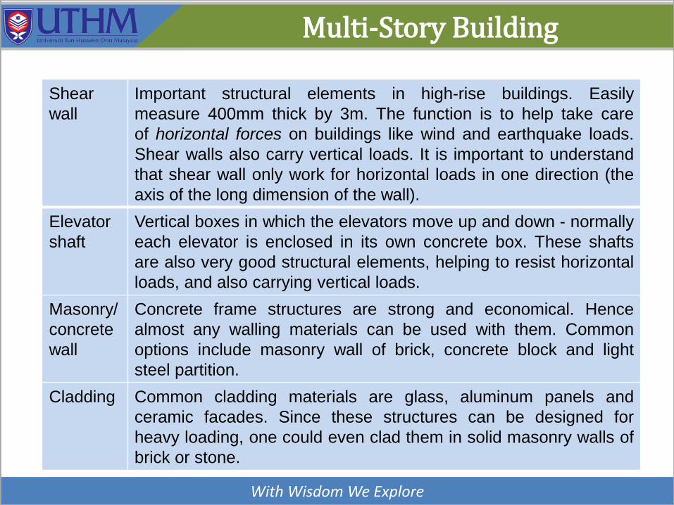
Important structural elements in high-rise buildings. Easily
measure 400mm thick by 3m. The function is to help take care
of horizontal forces on buildings like wind and earthquake loads.
Shear walls also carry vertical loads. It is important to understand
that shear wall only work for horizontal loads in one direction (the
axis of the long dimension of the wall).
Elevator
shaft
Vertical boxes in which the elevators move up and down - normally
each elevator is enclosed in its own concrete box. These shafts
are also very good structural elements, helping to resist horizontal
loads, and also carrying vertical loads.
Masonry/
concrete
wall
Concrete frame structures are strong and economical. Hence
almost any walling materials can be used with them. Common
options include masonry wall of brick, concrete block and light
steel partition.
Cladding Common cladding materials are glass, aluminum panels and
ceramic facades. Since these structures can be designed for
heavy loading, one could even clad them in solid masonry walls of
brick or stone.

With Wisdom We Explore
Multi-Story Building
Building is 3D frame which consist of slabs, beams and columns

With Wisdom We Explore
Multi-Story Building
Multi-story building: Low-rise vs High-rise

With Wisdom We Explore
Frame Analysis
▪The building structure is 3D frame, comprising floor slabs,
beams, columns and footings, which monolithically connected
and act integrally to resist vertical loads and lateral loads.
▪ In the design of reinforced concrete structures, it has to analyze
the structure subjected to all probable combinations of loads,
considering the ultimate limit state.
▪Commonly 3D frame analysis is the most accurate method to
analyse the frame building. However, 3D frame is complex and
need to be carried out using relevant computer software
(ESTEEM, STAADPro, ETABS, SAP, finite element software,
etc.)
▪Once the bending moment, shear force and axial load are
obtained, reinforcements can be designed according to the
standard.

With Wisdom We Explore
Frame Analysis
▪ In many cases the slabs are analyzed separately, thus, the
analysis may be simplified appropriately consist only beams and
columns.
3D frame which consist of
slabs, beams and column
3D frame consist only beams and
columnsSimplified

With Wisdom We Explore
Frame Analysis
▪ In order to simplify the analysis, the 3D structure is generally
divided into a series of independent parallel 2D plane frames.
View-X View Y

With Wisdom We Explore
Frame Analysis
▪ 2D plane frame can be further simplified into 3 levels sub-frames:
i) Complete sub-frame
The frame consists of all beams at each level with columns
top and bottom of beams. Moments at columns and beams
are tabulated by analyzing the complete sub-frame.
ii) Simplified sub-frame
The frame consists of a selected beam with columns and
neighbouring beams at both sides of selected beam.
iii) Simplified sub-frame at point
The frame consists of a selected point or node with columns
at top and bottom, and neighbouring beams coming into the
point.

With Wisdom We Explore
Frame Analysis
▪ 2D plane frame >>> complete sub-frame
A B C D E
A B C D ESecond
floor
First
floor
Roof
Complete 2D Frame
Sub-frame at second floor

With Wisdom We Explore
Frame Analysis
▪Complete sub-frame >>> Simplified sub-frame
A B C D ESecond
floor
First
floor
Roof
A B C D A B C
Complete 2D Frame
Simplified sub-frame beam BC Simplified sub-frame beam AB

With Wisdom We Explore
Frame Analysis
▪Simplified sub-frame >>> One point sub-frame:
A B C D ESecond
floor
First
floor
Roof
A B B C D
Complete 2D Frame
Simplified sub-frame at point A Simplified sub-frame at point C

With Wisdom We Explore
Type of Frame
1) Braced Framed
Frames that not
contribute to the overall
stability of the structure.
None of the lateral
actions, including wind,
are transmitted to the
columns and beams but
carries by bracing
members such as shear
wall.
Support vertical actions
only.

With Wisdom We Explore
Type of Frame
2) Unbraced Framed
Frame that contribute to
the overall stability of the
structure.
All lateral actions,
including wind, are
transmitted to the
columns and beams
since there are no
bracing members such
as shear wall are
provided.
Support vertical and
lateral actions

With Wisdom We Explore
Method of Analysis
▪Primary objective is to
obtain a set of internal
forces and moments
throughout the structure
that are in equilibrium with
the design loads for the
required loading
combinations.
▪General provisions to
analysis are set out in EN
1992-1-1 Section 5.
Braced Frame Unbraced Frame
Vertical loadVertical load + Horizontal load
Load transfer from slabs to
beams
Load transfer from slabs to
beams ; wind to column
Design action patterns: maximum-minimum
Moment distribution method
Fixed end moments, Shear forces, Bending moments

With Wisdom We Explore
General Consideration
▪General consideration for sub-frame analysis:
i) Method of sub-frame analysis can be conducted using one-
level sub-frame, two-point sub-frame or one-point sub-frame
with continuous beam.
ii) The column or/and beam ends remote from the beam under
consideration may generally be assumed to be fixed unless
the assumption of pinned is clearly more reasonable.
iii) Stiffness for interior beam is KB.
iv) Stiffness for fixed end (beam elements) posses half their
actual stiffness, 0.5KB.
v) The arrangement of the design ultimate variable loads
should be such as to cause the maximum moment the
column.

With Wisdom We Explore
Sub-Frame Analysis
▪One-level sub-frame
- Each sub-frame consist of the beams at one level together with
the columns above and below.
- The ends of the columns remote from the beams may generally
be assumed to be fixed unless the assumption of a pinned end
is clearly more reasonable
- At least four cases combination of actions:
[Max][Min][Max]; [Min][Max][Min]
[Max][Max][Min]; [Min][Max][Max]
KB1 KB2 KB3

With Wisdom We Explore
Sub-Frame Analysis
▪Two-point sub-frame
- The moments and forces in certain individual beam may be
found by considering a simplified sub-frame consisting only of
the beam, the columns attached to the end of that beam and
the beams on either side is any.
- Load at interior beam where stiffness = KB is always for
maximum design load.
KB1 0.5KB2 0.5KB1 KB2 0.5KB2

With Wisdom We Explore
Sub-Frame Analysis
▪One-point sub-frame with continuous beam
- The moments and forces in the beams at one level →
considering the beams as a continuous beam over supports
providing no restraint to rotation.
- The ultimate moment for column → simple moment distribution
procedure
0.5KB1 0.5KB1 0.5KB2 0.5KB3

With Wisdom We Explore
Combination of Actions
▪Action on buildings is due to permanent (dead load), variable
(imposed, wind, dynamic, seismic loads) and accidental load.
▪Mostly multistory buildings for office or residential purpose are
design for dead, imposed and wind loads.
▪Separate actions must be applied to the structure in appropriate
directions and various types of actions combined with partial
safety factors selected to cause the most severe design
condition.
▪Maximum design load = 1.35Gk + 1.5Qk
▪Minimum design load = 1.35Gk
▪Wind load = 1.2Wk
▪Vertical load due to wind = 1.2Gk + 1.2Qk

With Wisdom We Explore
Combination of Actions
▪For the combination of dead load and imposed load, the
following loading patterns are considered:
Braced frame 1) All spans loaded with maximum dead plusimposed loads
2) Alternate spans loaded with maximum deadload and imposed load and all other spansloaded with minimum dead load
Unbraced frame 1) Three cases loading arrangements as
braced sub-frame
2) Vertical actions for sub-frame
3) Wind load for complete frame

With Wisdom We Explore
Combination of Actions
▪ Load cases for braced frame
▪Vertical load
[Max] [Max] [Max]
[Min ] [Min ] [Min ]
[Max] [Min ] [Max]
[Min ] [Max] [Min ]
[Max] [Max] [Min ]
[Min ] [Max] [Max]
MinMaxMax
Max MinMin
MaxMinMax

With Wisdom We Explore
Combination of Actions
▪ Load cases for unbraced frame
▪Vertical load from wind loading + lateral load
A1 B1 C1 D1
A2 B2 C2 D2
A3 B3 C3 D3
1.2GK +1.2QK 1.2GK +1.2QK 1.2GK +1.2QK
A1 B1 C1 D1
A2 B2 C2 D2
A3 B3 C3 D3
1.2WK
1.2WK
1.2WK
1.2WK

With Wisdom We Explore
Analysis Procedure
▪Analysis procedure for braced frame:
1. Analyse all actions, maximum and minimum design loads
2. Calculate moment inertia, I = bh3 /12
3. Calculate stiffness of beams and columns, k = I/L
4. Determine distribution factor, DF = ki / Σk
5. Determine fixed end moment (FEM) of beams
6. Perform moment distribution by cases:
a) Case 1 [Max][Max][Min]
b) Case 2 [Min][Min][Max]
c) Case 3 [Max][Min][Max]
d) Case 4 [Min][Max][Min]
7. Calculate actual shear force and bending moment. Draw
BMD and SFD diagrams

With Wisdom We Explore
Analysis Procedure
▪Analysis procedure for unbraced frame:▪ 1
1. Calculate design wind load, Wd=1.2Wk
2. Calculate lateral point load at each level of frame
a) Assume contra-flexure point at center of frame
b) Axial loads in column are in its proportion to distances
from the centre of gravity of frame
c) All columns are equal cross-section area
3. Lateral load analysis using Cantilever Method.
- Calculate axial force in columns, then shear force in
beams and columns from top to ground levels.
4. Vertical load analysis due to wind, 1.2 Gk + 1.2Qk
- analysis of one level sub-frame

With Wisdom We Explore
Example
The framing plans for a multistory building are shown in the figure.
The main dimensions structural features, loads, material, etc. are
also set out as at the given data. Analyze sub frame 3/A-D, Level 1
to determine shear forces and bending moments of corresponding
beams and columns. Use all the three methods of analysis.
- Permanent office building (Design life = 50 years)
- Location: Near sub-urban (Zone 1 of Malaysia wind speed
mapping)
- Topography: Flat area–slope<0.05 (Building around within 1 KM
radius)
- Beam in grid line 1,2,3…12 : 250 x 600 mm
- Beam in grid line A, B, C & D : 250 x 500 mm
- Slab thickness = 150 mm
- Columns : 300 x 400 mm
- Imposed load : 4.0 kN/m2
- Finishes, ceiling, services etc : 0.75 kN/m2 ; Partitions : 0.5 kN/m2

With Wisdom We Explore
Example
Figure 2.1

With Wisdom We Explore
Example
▪Step analysis of braced frame:
1. Analysis actions on beam (load transfer from slab,
selfweight and wall)
2. Calculate moment of inertia for beams and columns,
I = bh3 /12
3. Calculate stiffness, k = I/L
4. Calculate distribution factor, DF= ki / Σk
5. Determine carry over factor, CF=0.5 ( for pin support)
6. Determine Fixed End Moment,
FEM=wl2/12 (for uniform load)
7. Moment distribution by cases:
- Case 1 [Span 1,2: max / span 3: min]
- Case 2 [Span 1: min / span 2,3: max]
- Case 3 [Span 1,3: max / span 2: min]
- Case 4 [Span 1,3: min / span 2: max]
8. Draw BMD and SFD diagrams

With Wisdom We Explore
Example
▪Action on beam:

With Wisdom We Explore
Example
▪Action on beam:

Example
▪Action on beam:
With Wisdom We Explore

With Wisdom We Explore
Example
▪Action on beam:

With Wisdom We Explore
Example
▪Action on beam:

With Wisdom We Explore
Example
▪Action on beam:

With Wisdom We Explore
Example
▪Analysis of one level sub-fame

With Wisdom We Explore
Example
▪Analysis of one level sub-fame

With Wisdom We Explore
Example
▪Analysis of one level sub-fame

With Wisdom We Explore
Example: One Level Sub-Frame
▪Analysis of one level sub-fame : CASE 1
Max Min

With Wisdom We Explore
Example: One Level Sub-Frame
▪Analysis of one level sub-fame : CASE 1
Beam Column
- (BA+BC)

With Wisdom We Explore
Example: One Level Sub-Frame
▪Analysis of one level sub-fame : CASE 1

With Wisdom We Explore
Example: One Level Sub-Frame
▪Analysis of one level sub-fame : CASE 1

With Wisdom We Explore
Example: One Level Sub-Frame
▪Analysis of one level sub-fame : CASE 1

With Wisdom We Explore
Example: One Level Sub-Frame
▪Analysis of one level sub-fame : CASE 2
MaxMin

With Wisdom We Explore
Example: One Level Sub-Frame
▪Analysis of one level sub-fame : CASE 2
With Wisdom We Explore
Example: One Level Sub-Frame
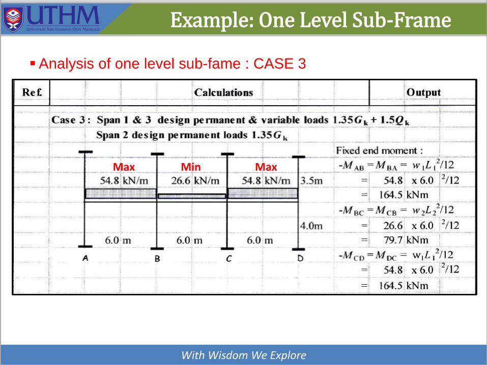
▪Analysis of one level sub-fame : CASE 3
Max Min Max

With Wisdom We Explore
Example: One Level Sub-Frame
▪Analysis of one level sub-fame : CASE 3
With Wisdom We Explore
Example: One Level Sub-Frame
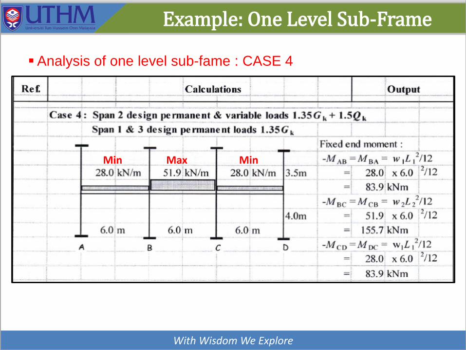
▪Analysis of one level sub-fame : CASE 4
Max MinMin

With Wisdom We Explore
Example: One Level Sub-Frame
▪Analysis of one level sub-fame : CASE 4

With Wisdom We Explore
Example: One Level Sub-Frame
▪Analysis of one level sub-fame : ENVELOPE

With Wisdom We Explore
Example: Two Point Sub-Frame
Max Max
With Wisdom We Explore
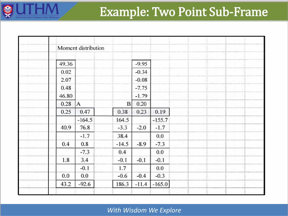
Example: Two Point Sub-Frame

With Wisdom We Explore
Example: Two Point Sub-Frame
Max Min

Example: Two Point Sub-Frame
With Wisdom We Explore

Example: Two Point Sub-Frame
With Wisdom We Explore

With Wisdom We Explore
Example: Two Point Sub-Frame

With Wisdom We Explore
Example: Two Point Sub-Frame

With Wisdom We Explore
Example: Two Point Sub-Frame

With Wisdom We Explore
Example: Two Point Sub-Frame

With Wisdom We Explore
Example: Two Point Sub-Frame

With Wisdom We Explore
Example: Two Point Sub-Frame

With Wisdom We Explore
Example: Two Point Sub-Frame

With Wisdom We Explore
Example: One Point Sub-Frame

With Wisdom We Explore
Example: One Point Sub-Frame

With Wisdom We Explore
Example: One Point Sub-Frame

With Wisdom We Explore
Example: One Point Sub-Frame

With Wisdom We Explore
Example: One Point Sub-Frame

With Wisdom We Explore
Example: One Point Sub-Frame

With Wisdom We Explore
Example: One Point Sub-Frame

With Wisdom We Explore
Example: One Point Sub-Frame

With Wisdom We Explore
Example: One Point Sub-Frame

With Wisdom We Explore
Example: One Point Sub-Frame

Example: One Point Sub-Frame
With Wisdom We Explore

With Wisdom We Explore
Example: One Point Sub-Frame

With Wisdom We Explore
Example: One Point Sub-Frame

With Wisdom We Explore
Example: One Point Sub-Frame

With Wisdom We Explore
Example: One Point Sub-Frame

With Wisdom We Explore
Example: One Point Sub-Frame

With Wisdom We Explore
Example: One Point Sub-Frame