^^ facilities for insect research and production
TRANSCRIPT

TB 1576/6/78
^^ FACILITIES FOR INSECT RESEARCH AND PRODUCTION
'Sa S
-o I
>
cnC-
S PO
PO
/^x UNITED STATES (à â J) DEPARTMENT OF
^^^ AGRICULTURE
TECHNICAL BULLETIN NUMBER 1576
PREPARED BY SCIENCE AND EDUCATION ADMINISTRATION


FACILITIES FOR INSECT RESEARCH AND PRODUCTION EDITED BY NORMAN C LEPPLA AND TOM R. ASHLEY
INSECT ATTRACTANTS, BEHAVIOR, AND BASIC BIOLOGY RESEARCH LABORATORY SCIENCE AND EDUCATION ADMINISTRATION P.O. BOX 14565, GAINESVILLE, FLA. 32604
USDA, National Agiloultural Library NAL Bldg 10301 Baltimore Blvd Beltsville, MD 20705-2351
/^^ UNITED STATES TECHNICAL PREPARED BY lUJ) DEPARTMENT OF BULLETIN SCIENCE AND
"^ AGRICULTURE NUMBER 1576 AKíAÍSTRATION

On January 24, 1978, four USDA agencies—Agricultural Research Service (ARS), Cooperative State Research Service (CSRS), Extension Service (ES), and the National Agricultural Library (NAL)—merged to become a new organization, the Science and Education Administration (SEA), U.S. Department of Agriculture.
This publication was prepared by the Science and Education Adminis- tration's Federal Research staff, which was formerly the Agricultural Research Service.
Washington, D.C. Issued June 1978
For sale by the Superintendent of Documents, U.S. Government Printing Office Washington, D.C. 20402 (paper cover)
Stock No. 001-000-03767-6

FOREWORD
The design of facilities for culturing insects is, or should be, a key- topic in the broader subject of insect rearing. Facilities design, however, has too often been relegated, figuratively and literally, to the closet and back shelf. In fact, deliberate and thorough planning of production facili- ties has been the exception. There appears to be an erroneous assumption among many entomologists that insect tolerance of and adaptability to primitive rearing conditions cannot be reflected in their research results.
This is not to say that the development of physical environments for insect colonization has not received attention. A compendium of methods for culturing invertebrate animals prepared by Needham (1937) includes more than 150 articles, many of them about techniques and simple facili- ties. One of the most detailed examples, by White, describes sophisticated facilities for producing sterile blow fly larvae for use in the postoperative treatment of chronic osteomyelitis and other suppurative conditions and cites an urgent need for maggots suitable for surgical use. Conversely, the article on boll weevil culture, by Fenton, contains about 150 words, three of which are '*no adequate information"; suggested facilities for boll weevil culture are large lantern globes or jelly tumblers.
Needham clearly identified the basic requirements for successful rear- ing: (1) Food, (2) protection from enemies, (3) a suitable physical en- vironment, and (4) fit conditions for reproduction. More recently, the National Academy of Sciences, National Research Council Subcommittee on Insect Pests (1969), in considering insect mass production, identified the researchable refinements of these elements as (1) inexpensive stan- dardized media, (2) techniques for extracting insect stages from their media, (3) techniques for providing acceptable high-density space use, (4) full understanding of the chemical and physical stimuli mediating mat- ing and oviposition, (5) prophylaxis, and (6) maximum automation. They also stressed dependability, efficiency, and quality. Many of these elements lie within the scope of this bulletin.
Sponsorship of this bulletin is part of the continuing concern by the Agricultural Research Service for adequate exchange of information among scientists engaged in research related to insect rearing. Major workshops have been conducted by the Service, such as the "Planning and Training Conference for Insect Nutrition" held in 1963. In 1974 a workshop on the "Genetics of Insect Behavior" emphasized genetics in the performance of laboratory-reared insects and the possible modification of performance through genetic and nongenetic effects imposed by rearing and selection procedures. While such workshops are highly beneficial, we hope that the broader contribution to and availability of this bulletin will facilitate even greater information exchange.
It is axiomatic that the ability to colonize insects under managed con- ditions is fundamental to virtually every aspect of entomological endeavor. Pest-management schemes have actually come to rely upon rearing facili- ties, just as military strategists rely upon munitions plants. Moderate-size cultures of beneficial parasitoids and predators for inoculative releases are

being supplemented by large-scale production for mass releases over exten- sive geographical areas. Autocidal control measures rely absolutely upon massive releases for imposition of sterility on natural populations. Thus, the ready and constant availability of specimens makes possible the con- sideration of pest-control options not otherwise available and facilitates associated research. Substantial numbers of insects are required for testing toxicants and behavior- and growth-modifying chemicals, as well as for basic studies of the mechanisms involved in these and other physiological phenomena. The study of insecticide resistance, genetics, host interaction, insect pathology, epidemiology, transmission of insect-borne diseases, insect-related allergies, and other critical areas also consume large numbers of tesl insects.
To accomplish the intended research or control, the lab-reared insect must possess a genotype similar to that of its native counterpart. Thus, a sine qua non for colonization is a facility that assures adequate production without unduly compromising the quality of its product. This is accom- plished through a dedicated and highly informed management that co- ordinates a system encompassing facilities, personnel, materials, procedures, and protocols. Success will be achieved to the extent that management is able to balance this complex system through controlled inputs and adequate feedback.
The contrast is marked between contemporary mass-rearing factories and the first attempts to colonize insects. Many of the objectives for which insects are cultured have also changed. It is hoped that the presentations herein will demonstrate the dynamic nature of this entomological specialty and contribute to its development.
DERRELL L. CHAMBERS Director, Insect Attractants, Behavior,
and Basic Biology Research Laboratory, Science and Education Administration

PREFACE Most contemporary Federal, State, and industrial entomological labora-
tories maintain colonies of insects for research on insecticides, repellents, attractants, insect pathology, plant and animal resistance and disease transmission, biological and autocidal control of insects, and related sub- jects. This circumstance prompted E. F. Knipling (1966) to state that **as research delves into more fundamental aspects of entomology, and as various new approaches to insect control emerge, scientists are beginning to realize that successful insect colonization is a basic necessity for efficient and productive research on virtually every aspect of entomology.'' Ade- quate physical environments are essential to the pursuit of this important work and are required to study life histories, population dynamics, and physiological, behavioral, and other ecological phenomena (Flitters et al. 1956; Atmar and Ellington 1972). Because of this emphasis on controlled environments, an International Atomic Energy Agency panel (1968) actu- ally advocated development of designs for insect-rearing '^factories.'* This bulletin is intended to provide such designs for establishment of facilities for entomological research and insect production.
This bulletin includes 28 articles that are formally classified into 4 sections. The first two sections, "Bioclimatic Chambers" and "Room-Size Units," provide the basis for Sections 3 and 4, "Quarantine Facilities" and "Large-Scale Facilities." Each section describes innovative designs that range from uncomplicated to complex. Each article is structured to insure a terse yet adequate description of the facility; precise data and thorough illustrations are emphasized.
It should be noted that the facility described in the article "Controlled- Environment Room," though not specifically mentioned as a facility for insect research and production, is one of the foremost systems for studying the effects of environmental factors on plant growth, and many phyto- phagous insects cannot be studied adequately without such precise control of their hosts.
Articles were solicited from individuals, irrespective of their national- ity or sponsoring institution, that had published on the subject previously. In addition, advertisements were placed in entomological journals and newsletters. No one was excluded from participation; however, many im- portant facilities are presented only as bibliographical entries. Therefore, the bulletin is composed of a range of tested designs and a comprehensive catalog of existing options. It is assumed that the reader will pursue a particular interest by seeking the relevant literature and modifying a pub- lished system, by contacting an appropriate expert, or by simply adopting one of the presented facilities. Ultimately, a compromise will be achieved between specificity of intended use and adaptability of the physical environment for future application.
The bibliography was assembled by searching information systems, using "design," "chambers," "systems," "facility," "rearing," "cage," and "greenhouse" as keywords, and by searching the Bibliography of Agricul- ture, National Agricultural Library Catalog, Dictionary Catalog of the

National Agricultural Library, Monthly Catalog of United States Govern- ment Publications, and Biological Abstracts, from 1926 to August 1976. In addition, reference lists in individual books and articles were frequently reviewed for citations that might have been omitted from the initial search. Thus, the bibliography includes references to many additional facilities, associated insect-rearing methods and equipment, and a few important re- views and symposia. Research on insect nutrition, colonization, and related technology is beyond the scope of this bulletin.
The prevalent requirements for relatively simple, inexpensive, reliable, and efficient facilities are ample justification for advocating these custom- built systems (White and Debach 1960; Wagner et al. 1965; Platner et al. 1973). Insect research and production facilities are an integral part of existing entomological programs, and their designs are always dependent on locally available materials. This technical bulletin will be of particular use in planning future construction or renovation, assisting entomologists who are constrained by limited resources, and supporting scientists who lack construction experience. The subject matter may also provide a means of effectively coordinating the use of existing facilities for multi- disciplinary research.
N. C. L T. R. A.

CONTENTS Page
Foreword îiî Preface v
SECTION 1.—BIOCLIMATIC CHAMBERS
Bioclimatic Cabinet for Insect Rearing and Research T, R. Ashley and P. D. Greany 3
Versatile Semisealed Insect-Rearing Chamber W, A. Dicker son, /. D. Hoffman, F. R. Lawson, and J. B, Brown . 5
Conversion of a Refrigerator to a Bioclimatic Chamber /. C. Allen and E. J. Lojko 6
Movable Rearing Cabinets A, MacPhee 8
Environmental Cabinet with Variable Airflow K. R. Scott 10
Multipurpose Environmental Chamber R. E. Wagner 13
Programmable Environmental-Chamber Control System /. W. Atmar, M. A. Ellstrom, M. D. Bradley, and J. J. Ellington .. 16
SECTION 2.—ROOM-SIZE UNITS
Room-Size System for Rearing Lepidoptera R. L. Burton 25
Room for Rearing House Flies and Stable Flies R. S. Patterson 26
Modular Rooms for Modification of Ambient Laboratory Environ- ments N. C. Leppla and S. L. Carlyle 28
Controlled-Environment Room M. C. Hampson 30
Facility for Culturing Microhymenopteran Pupal Parasitoids P. B. Morgan and R. S. Patterson 32
Insect-Rearing Rooms A. N. Kishaba 34
Temporary Insect-Rearing Facility J. B. Beavers 35
Small Plant for Production of Trichoplusia NPV F. R, Lawson and R. L. Headstrom 37
Inexpensive Facility for Mass Rearing of Insects y. A. Gasparotto 39
Rearing, Research, and Teaching Facility R. P. Smith 40
SECTION 3.—QUARANTINE FACILITIES
University of California Quarantine Facility, Albany L. K. Etzel 45
vii

Page Quarantine and Biological-Control Laboratory
H, A. Denmark 47 USDA Quarantine Facility, Newark, Delaware
L. R. Ertle and W. H. Day 49 Quarantine Laboratory for Plant-Feeding Insects
/. C. Bailey and J. B. Kreasky 53 University of California Quarantine Facility, Riverside
T. W. Fisher 56
SECTION 4.—LARGE-SCALE FACILITIES
Facility for Large-Scale Rearing of Tephritid Fruit Flies N. Tanaka 63
Rearing Facility for Vegetable and Sugarbeet Insects J. W. Deholt and M. A. Petterson 64
Custom Insect-Rearing Facility N. C. Leppla, S. L, Carlyle, C. W. Green, and W, J. Pons 66
Modified Facility for Host and Parasitoid Rearing C. W, Gantty F. D. Brewer, and D. F, Martin 70
Media-Preparation and Brood-Colony Facility F. D. Brewer, C. W. Gantt, and D. F. Martin 72
Pilot Facility for Mass Rearing of Boll Weevils J. G. Griffin and 0, H, Lindig 75
Bibliography 79 viii

SECTION 1 BIOCLIMATIC CHAMBERS
263-699 O - 78 - 2


BIOCLIMATIC CABINET FOR INSECT REARING AND RESEARCH
T. R. ASHLEY and P. D. GREANY Insect AttractantSj Behavior, and Basic Biology Research Laboratory
Science and Education Administration P.O. Box lU565y Gainesville, Fla. 3260A
Initially, this environmental cabinet was built for maintaining colonies of insect parasitoids (fig. 1-1). It was designed to be inexpensive, dependable, uncomplicated, and portable. The cabinet is equipped with four basic systems: (1) Heating, (2) humidification, (3) lighting, and (4) protection against electrical and temperature overrun.
SPECIFICATIONS
Heating.—Air leaves the upper portion of the cabinet, passes down the poly vinyl chloride (PVC) pipe (B), and is forced by the blower (A) around the heating element (J) and over the coils of the thermostat (K). The short, 4.4- cm distance between the heating element and the thermostat coils minimizes temperature fluctuations. If temperatures greater than 30° C are required, this distance must be in- creased to permit greater cooling of the thermo- stat during periods when the heating element is off.
Humidification.—Relative humidity is regu- lated by a humidistat (L), and air saturated with water is produced by a vaporizer (I). The moist air is forced from the vaporizer up through the PVC pipe and out of the vaporizer exit hole (H) at the top of the cabinet. This system circulates the air more efficiently, elimi- nates large water droplets from the moist air, and reduces water condensation within the cabinet.
Lighting.—Two Vita-lite lamps provide 65 fc at the floor of the cabinet and 95 percent of the wavelengths produced by the sun. The diffusing material located below the lights is installed to distribute the light more evenly. The photo- period is controlled by an interval timer (F).
Protection.—The cabinet is equipped with a 3-A fuse and a high-cutout thermostat (G). The fuse holder is installed in the base of the
timer (F), and the high-cutout thermostat is positioned so that circulating air passes over the sensing coils of the thermostat.
CONSTRUCTION
The 0.9- by 0.8- by 0.6-m cabinet is con- structed of plywood. The equipment is selected mainly on the basis of availability and price; thus, flexibility exists in choosing the compo- nents (table 1-1). The cabinets described herein cost about $150 in 1974, excluding labor. The door (not illustrated) is fastened to the cabinet by a piano hinge and is kept shut with two sash locks. A long-stemmed dial thermom- eter is inserted through the door at the upper
TABLE 1-1.—Major components for bioclimatic cabinet
Reference letter Component
(fig. 1-1)
A Pole blower, 7.1-1/s (Dayton 2C782)
B PVC pipe, 3.8-cm-diameter, (1.5 m) ; 4 elbows, IT
F Time switch, 24-h (IntermaticT 103)
G,K Thermostat, single-stage. -l.l°±3°tol00°±3° C (Dayton 2E206)
I Humidifier, 19-1 (Northern Electric E37554, style No. 45)
J Heating element, Glo-Coil, 660-W (Superior 2254)
L Dehumidifier control. 20%±5% to80%±5% RH (Honeywell 46E1013)
M Fluorescent lamp fixture, 61-cm (Southern 11224)
— Fluorescent lamp. Vita-lite, 20-W (Duro-Test 3028)

PN-5806 FIGURE 1-1.—Side and front views of bioclimatic cabinet. A, Blower. B, PVC pipe. C, Air-intalce hole. D, Vaporizer
connection. E, Fluorescent ballast. F, Timer. G, High-cutout thermostat. H, Vaporizer exit hole. I, Vaporizer. J, Heating element. K, Thermostat. L, Humidistat. M, Lights. N, Supports for mounting metal shelf brackets.
left corner just below the light-diffusing ma- terial. The motor of the blower is rotated 180° so that the oil holes are pointing upward. The original outlet in the vaporizer is covered with Plexiglas, which is secured in place with hot glue. The lower one-fourth to one-third of the opening (H) at the end of the PVC pipe is covered with Plexiglas to prevent the condensa- tion on the inside of the pipe from being blown into the cabinet. The humidistat is really a dehumidistat; it was altered so that current would be transmitted to the vaporizer in re- sponse to a drop in RH. The floor (not illus- trated) is made of pegboard and is held in place by metal shelf brackets (located at points N). This arrangement permits the floor to be re- positioned for changes in light intensity. The ballast (E) for the fluorescent lamps is mounted externally because of the heat it pro- duces. A piece of asbestos is located on each side of the heating element (J) to protect the inside wall and vaporizer.
OPERATION AND EVALUATION Temperature fluctuations within the cabinet
are ±0.5° C. Relative humidity fluctuations are greater than that because the moist air enter- ing the cabinet is almost completely saturated. However, these fluctuations can be reduced to ±3 percent by placing the organisms into cages with solid tops and side ventilation pores. The lower the air-exchange rate between the cabinet and the cages, the smaller will be the humidity fluctuations. The temperature and RH settings cannot be less than the ambient conditions of the room where the cabinets are located because no provisions were made for cooling or de- humidification. Temperatures of 26° to 32° C and humidities of 55 to 85 percent are maintained in the cabinets for experiments.
Six of these cabinets have been in continuous operation since 1974, and only the motor in one of the vaporizers has been replaced. Suggested

modifications in the design include adding an observation window in the door; placing the vaporizer at the rear of the cabinet and moving the blower, heating element, and thermostat to
the front; and installing an externally mounted light or alarm that would be actuated if the high-cutout thermostat turned off the heating element or a fuse burned out.
VERSATILE SEMISEALED INSECT-REARING CHAMBER
W. A. DICKERSON, J. D. HOFFMAN, F. R. LAWSON, and J. B. BROWN Biological Control of Insects Research Laboratory
Science and Education Administration Columbia, Mo. 65201
This unit was constructed to provide precise, constant, manually adjustable environments for rearing insects. The design provides simple and accurate temperature and humidity control, and since all entering air is filtered, the unit vir- tually eliminates airborne contaminants. The chamber was built to prevent infestation of an Angoumois grain moth, Sitotroga cerealella (Oliver), colony by the predaceous straw itch mite, Pyemotes ventricosus (Newport), and also has been used to rear the corn earworm, Heliothis zea (Boddie), and cabbage looper, Trichoplusia ni (Hübner).
CONSTRUCTION AND SPECIFICATIONS
The 88.9- by 59.0- by 58.4-cm unit is con- structed of 1.9-cm-thick plywood and is pro-
vided with a door made from two parallel sheets of 0.3-cm-thick Plexiglas separated by a 1.3-cm insulating air space (fig. 1-2). The internal surfaces of the cabinet are lined with 2.5-cm- thick polystyrene foam covered by Formica and sealed with silicone calking. Most of the compo- nents are readily available, and the radiator can be salvaged from a discarded window air conditioner. All lights and motors are mounted externally to reduce the internal heat load. The only additional requirements are a source of hot and cold water, drain, 110-V electricity, and compressed air. The total cost of materials was approximately $100 in 1974.
Temperature.—Constant temperatures can be maintained by regulating the ratio of hot (54° C) and cold (18° C) water that flows through the radiator. The chamber is controlled at ±1° C by adjusting a hand-operated mixing
r
^i
-COMPRESSED- AIR INTAKE
-AIR OUTLET
7ÍÍ
\ \
LM KOH/HgO PAN
/- INSECT-HOLDING TRAY
TRAY SLIDE TRAY GUIDE
HUMIDITY 1|^ PROBE
SCREEN BOTTOM y^
zr-
M
Í ^L
ß
^r POLYSTYRENE F^AM ^r-3/4 " PLYWOOC
TEMPERATURE PROBE
"-DOOR LATCH
FIGURE 1-2.—Diagram of rearing chamber (front view).

valve (Delta), and uniform air circulation is provided by a fan. When monitoring is neces- sary, temperature and RH probes are mounted in the chamber.
Humidity,—Relative humidity ranging from 30 to 100±2 percent is maintained by moving the air over a baffled pan of potassium hydrox- ide solution. The resulting RH is inversely pro- portional to the KOH concentration (Buxton and Mellanby 1934).
Photoperiod,—Two 30-W Grolux and two Cool White fluorescent lamps are connected to an interval timer and mounted on the outside of the Plexiglas door.
Airborne contamination control—The unit is constructed to be airtight with the door closed. Compressed air is filtered through a Millipor
filter vented by a water trap and introduced into the system at a rate of 12 1/min. Between insect generations, the chamber is washed with 0.5 percent aqueous sodium hypochlorite and fumigated for 48 hours with formaldehyde.
EVALUATION
Since 1974, this chamber has been ideal for conducting insect-rearing experiments or for maintaining small cultures of insects under constant environmental conditions. The limited cooling capacity can be supplemented by using a refrigerated coil to cool and recirculate the water. Since the fan motor and mixing valve are the only moving parts in the system, routine maintenance involves just the filters and lamps.
CONVERSION OF A REFRIGERATOR TO A BIOCLIMATIC CHAMBER
J. C. ALLEN and E. J. LOJKO Agricultural Research and Education Center
University/ of Florida Lake Alfred, Fla. 33850
This chamber was built to provide a means of measuring the effects of environmental vari- ables on the survival and development of insects and mites (fig. 1-3). It can be constructed from easily obtainable components and with very limited knowledge of electronics or control cir- cuitry. The chamber provides heating and cool- ing under feedback control, plus humidity and photoperiod regulation.
SPECIFICATIONS
The outside dimensions of the complete unit are 180 by 90 by 90 cm, and the inside working area measures 90 by 55 by 52 cm. The chamber has optional removable shelves.
Temperature,—Internal temperatures of 5°± l°to45°±l°C are regulated by a commercially available Incutrol unit (F) that is manufac- tured for the express purpose of converting a refrigerator to a controlled-temperature cabi- net. This unit operates either the refrigerator or an internal heating element according to a potentiometer setting. It is provided with baffles and an internal fan for air circulation.
Humidity,—Relative humidity is controlled above ambiance by a humidifier (A) located on
top of the refrigerator, although some dehumid- ification is accomplished by the cooling coils. The humidistat (G), mounted internally on the rear wall of the refrigerator, is effectively a de- humidifier controller with reversed wires that cause the humidistat to actuate when humidity is below the manual setting. The original wiring actuates the humidifier in response to a decline in ambient RH. Air transport to the intake (K) and from the outlet (L) of the humidifier is through 3.2-cm wire-reinforced hose. The outlet is provided with a "periscope" of 3.2-cm poly- vinyl chloride (PVC) fittings (E) designed to catch large water droplets that would otherwise be blown into the chamber. Humidity control is from ambient to 100 =i= 5 percent, depending on the amplitude of the temperature oscillations.
Lighting,—Each chamber is provided with four 45.7-cm, 15-W Agrolite fluorescent lamps (I). These lamps are mounted outside the chamber on aluminum brackets (C), and the ballasts are mounted on the outside of these brackets. Light is admitted into the chamber through two 13.3- by 4.9-cm vertical slits (H). These slits are covered by 0.64-cm-thick Plexi- glas windows that are recessed into the side of the refrigerator. Changing lamps is facilitated

_ D
PN-5807
FIGURE 1-3.—Refrigerator converted to a bioclimatic cabinet. A, Humidifier. B, Time switch. C, Light bracket with external ballasts. D, Drain. E, Hu- midifier outlet. F, Incutrol temperature controller. G, Humidistat. H, Light windows. I, Lights mounted on hinged brackets. J, Terminal board. K, Humidifier intake. L, Humidifier outlet.
by hinges on one side of the mounting brackets (I). A time switch (B) provides control of the photoperiod.
CONSTRUCTION
The 0.36-nT'-capacity Coldspot refrigerator is modified mechanically and electrically as follows:
Mechanical.—The egg tray is removed from the inside of the door and replaced with a 1.25- by 0.27-m aluminum sheet. Slits for the lights are cut with a saber saw. These slits are 34 cm from the top and 12 cm from the front of the refrigerator, with 8.7 cm between the openings. The inner slit is smaller than the outer one so
FIGURE 1-4.—Hygrothermograph charts illustrating chamber performance. A&B, Normal operation showing effect of light cycle on temperature and humidity. C, Gradual increase in RH with lights off. D-F, RH in sealed Plexiglas box at 92% 72°, and 48° P with constant humidity.
as to leave a 0.5-cm lip of plastic for mounting the Plexiglas window (H), which is fastened in place with silicone sealer. The light brackets are constructed from sheet aluminum and are bent to allow the lamps to project as far as pos- sible into the slits, thus providing maximum light intensity within the chamber. The freezer door is removed to increase air circulation and cooling efficiency. A small plastic tube is ce- mented into the bottom of the water condensa- tion tray, and a neoprene tube is connected between this tube and the humidifier outlet (E). This outlet is drained by a second tube that ex- tends into an external receptacle (D). The In- cutrol unit (F) is mounted on Plexiglas brackets attached to the rear wall inside the

refrigerator, which isolates the unit and facili- tates its downward airflow pattern. The unit is connected to outside power by a four-wire waterproof trailer plug. The humidifier air in- take and outlet are sealed with aluminum-duct tape, and holes are drilled to provide for 3.2-cm PVC connecters. The wire-reinforced tubing is forced over the PVC to provide the air pathway.
Electrical,—All power connections are made at a central terminal board ( J) ; there- fore, only one plug is required to operate the entire chamber. The original refrigerator ther- mostat is removed and the wires are spliced, so the refrigerator operates whenever power is supplied by the Incutrol unit. The original thermostat hole is covered by an aluminum plate.
OPERATION
Because of the condensing action of the freezer compartment, humidity is increasingly more difficult to control as more cooling is re- quired in the refrigerator. Also, with the lights inside, the ballasts remote, and the chamber set at 24° C, so much cooling is required that the humidifier operates continuously, but the RH never exceeds 50 to 60 percent. However, this effect is reduced by placing the lights outside the chamber. Additional humidity control is achieved by placing a sealed Plexiglas box in- side the chamber and connecting the humidified air intake and outlet directly to the box. With the humidistat in the box, the system is modu- lated so that the RH gradually increases as the temperature declines. Thus, without requiring adjustment of the humidistat, the RH remains constant at temperatures of 33.3°, 22.2°, and 8.9° C (fig. 1-4).
TABLE 1-2.—Major components for refrigerator conversion
Reference letter Component
(fig. 1-3)
A Humidifier, 6-1 (Northern Electric E37554, style No. 46)
B Time switch, 24-h (Dayton 2E021)
F Temperature controller, Incutrol, 5°±1° to45°±l° C (Hatch Chemical 2597)
G Dehumidifier control, 20%±5% to 80%±5% RH (HoneyweU H46E1013)
L PVC pipe, 3.2-cm-diameter (0.95 m) ; 2 elbows
M Refrigerator, Coldspot, 0.36-m3 (Sears Roebuck 106.7631211)
EVALUATION
Excluding the plastic box for humidity modu- lation, materials for the chamber cost about $450 in 1975 (table 1-2). Unfortunately, three out of eight Incutrol units malfunction each year. Loops in the humidifier air tubes trap condensed water and block the airflow. A verti- cal PVC extension at the intake and output might solve this problem. Water also condenses on the inside aluminum door cover when the temperature and RH are relatively high. Some nonuniformity in internal conditions must exist, since the heat source is located in the Incutrol unit and there is only one humidity outlet. An additional circulating fan, externally located to reduce heat load, might be desirable.
MOVABLE REARING CABINETS
A. MACPHEE Research Station
Canada Department of Agriculture Kentville, Nova Scotia B4N 1J5
These semiportable cabinets maintain tem- perature, RH, and light regimes adequate for rearing mites and insects, including parasites and predators (fig. 1-5). They were built from readily available materials and from commer- cial sensor controls and fans. The insides of
the cabinets are free of obstructions, except for the humidity and temperature control sensors and the light fixtures. Temperature can only be controlled above ambiance. The cabinets have been in use since 1956, mostly during winter months, to study insect development, genetics.
8

t »
TABLE 1-3.—Major components for movable rearing cabinet
0
PN-B809 FIGURE 1-5.—Two movable rearing cabinets.
Reference letter Component
(fig. 1-6)
B Humidity control, wide-range (Honeywell H6A1X3)
C Heater fan, 1,550-r/min (Dominion Electrohome, Ontario, Canada,
186-43-05-lOE) C-1 Humidifier fan, 2,775-r/min
(Dominion Electrohome, Ontario, Canada, 197-43-05-05B)
D Humidifier plates (Vapoglas 490)
G Heater, 330-W (Central Scientific, Quebec, Canada,
95115-A) — Supersensitive relay
(American Instrument 4-5300) — Thermostat, all-purpose
(Fenwall 17500) — Humidifier float control
(Canadian General Electric, Nova Scotia)
520 1 (ñ
1 1
ll M
Ó lO
11 Í—26.0—'
N
(0
20-3 — 50-8 ' ^•
FIGURE 1-6.—Plans for cabinet. Left, front view with lower door removed. Right, rear view without wiring. A, Heater switch. B, Humidity controller. C & C-1, Blower fans. D, Humidifier. E & F, Air ducts. G, Heater. H, Junction box. Dimensions are in centimeters.
263-699 O - 78 - 3

and parasitism and to test artificial diets for lar- vae of the apple maggot, Rhagoletis pomonella (Walsh).
SPECIFICATIONS AND CONSTRUCTION
Each cabinet (fig. 1-6) is constructed of 1.9- cm-thick plywood without a supporting frame. Trays with perforated-steel bottoms are ar- ranged inside the cabinet on adjustable brack- ets. The cabinet has an upper door and a lower door, and the jamb between them may be re- moved to install trays. Both doors have double glass windows covered by outer plywood doors. A thermostat and a hygrostat (table 1-3) are installed on the inside wall of the chamber about 31 cm from the bottom. The cabinet sits on a base and is painted inside with steam- resistant epoxy to facilitate cleaning. Two 15-W fluorescent lamps, positioned inside at the top of the cabinets, produce 200 fc at a distance of 30.5 cm. The air ducts are made of sheet copper. Each chamber cost approximately $250 in 1956.
Temperature.—A continuously operated blower fan (C) removes air from the top of the cabinet and forces it down through the air duct (E), past a heater (G), and back into the bot- tom of the cabinet. A thermostat inside controls the 110-V power supply to the heaters. The heaters consist of two 165-W elements that are controlled by a three-way switch (A), allowing a choice of 82.5, 165, or 330 W. A relay between the thermostat and the heaters has been used in recent years to prolong the life of the thermostat.
Humidity,—When moisture is required, the hair hygrostat closes and actuates a relay that starts the fan motor (C-1). Air is blown over the moisture-soaked glass wicks in the humidi- fier (D), down through the air duct (F), and into the cabinet below the lower shelf. When
the moisture requirements are met, the blower fan switches off. The water level in the humidi- fier is maintained by a float control (B) that is fed by the main water supply.
OPERATION
The air ducts, fans, and doors of the cabinet must be nearly airtight, particularly when a high RH is required. The temperature fluctua- tion of ±1° C or less is satisfactory for rearing purposes. The RH varies from about a 3-percent differential at fine adjustment of the hygrostat to 7 percent at coarse adjustment. The maxi- mum RH obtainable is about 85 percent. If a controlled light-dark regime is required, a 24-h time clock is added to the system.
The rearing room containing the incubators is held to about 16° C, or to the outdoor tem- perature if it is greater, by a thermostatically controlled ventilation fan. Therefore, the cabi- nets can be operated from about 18° to 38° C most of the year. When cooler temperatures are required, two additional cabinets are used. These insulated cabinets are cooled by a re- frigerated brine system that provides for opera- tion down to 8° C. They are humidified by a steam generator that feeds steam into the air- circulation ducts. The cooling coils have a de- humidifying effect, allowing a wide range of humidity control in the cabinets.
EVALUATION
The cabinets have been in use 30 to 50 per- cent of the time since 1956 and have proven very reliable. The wicks in the humidifiers re- quire cleaning or replacement about every 6 months, depending on the purity of the water supply. The light intensity is relatively low, but it has been sufficient to trigger photoperiodic responses in the species studied.
ENVIRONMENTAL CABINET WITH VARIABLE AIRFLOW
K. R. SCOTT Freshwater Institute
Winnipegf Manitoba, Canada R3T 2N6
The cabinet is self-contained, rectangular, and caster mounted, and it has an upper work section with two large doors containing obser- vation windows (fig. 1-7). The machinery for
the cabinet is installed below the work section, and the electric controls are mounted at one end. The unit is designed with an air-circulation mechanism that permits studies on the effects
10

(: ,-^^^' B
PN-5810
FIGURE 1-7.—Environmental cabinet. A, Front view. B, Air diffuser at inlet to work section. C, Vanes that direct airflow. D, Evaporator coil and damper- control mechanism.
of changes in air velocity on the interactions of plants and insects.
SPECIFICATIONS
A front view of the 0.7- by 2.1- by 3.3-m cabinet shows the electronic controls and two 0.84-m- access doors (A). The stationary ply- wood air-diffusion grill (B) serves as the air inlet to the 0.6- by 0.8- by 1.8-m work section. Return-air turning vanes, fluorescent lights, a graduated damper-adjusting dial, and an air- flow indicator are mounted in the chamber (C). The two-speed vaneaxial fan, refrigeration coil, damper blades, operating sprocket, and return- air turning vanes are exposed in the rear (D).
Temperature.—Cooling is provided by a her- metic, water-cooled, 2-hp, high-temperature refrigeration compressor. An adjustable ther- mostat located at the entrance to the work sec- tion operates a solenoid valve that controls the flow of refrigerant to the finned cooling coil in the floor of the equipment section. A heater is not required in the system, since sufficient heat is provided by the fan motor and lights. Tem- peratures may be set at any desired value, from
FIGURE 1-8.—Diagram of environmental cabinet. A, Air turning vanes. B, Diffuser. C, Insect screen. D, Work section. E, Bypass damper. F, Evaporator coil. G, Coil damper. H, Fan. K, Refrigerator com- pressor. L, Ballasts for lamps and electric controls. M, Thermostat. N, Fluorescent lamps.
18°±0.7° to 35°±0.7° C. Air velocity can be regulated from 1.5 to 18.0 km/h (coefficient of variation is 20.3 percent at any level).
Humidity.—Relative humidity is not control- led, but a system could easily be added by in- stalling a spinning-disk humidifier in the lower chamber and a humidistat in the working section.
Photoperiod.—Lighting is provided by six fluorescent lamps. The light intensity is 32,940 Im/m- at 0.31 m below the lamps and decreases about 30 percent to 22,420 lm/m= at 0.61 m below the lamps. Ballasts are mounted outside to reduce the heat load on the refrigeration system.
Circulation.—Airflow is achieved by a 61-cm vaneaxial blower fan located in the lower equip- ment section. Airflow is regulated by a two- speed fan control, an adjustable damper, and a set of plywood diffuser grills.
CONSTRUCTION AND OPERATION
The construction materials consist primarily of wood framing and plywood (fig. 1-8). The unit is mounted on an angle-iron framework (5.1 by 5.1 by 0.5 cm) equipped with casters. Each of two large access doors is provided with a sealed double glass window. Removable access doors are fitted to the lower equipment com- partment, and insect-proof screens (C) are in- stalled at both ends of the work section (D).
11

TABLE 1-4.—Major components for portable environmental cabinet
Reference letter Component
(fig. 1-8)
F Evaporator coil, 74- by 46-cm-tube (Vapor 8R2-VDE)
H Vaneaxial fan, 2-speed, 61-cm-diameter (Buffalo Forge)
K Refrigeration compressor, 1.5-kW (Brunnermatic WR200H)
L Ballasts, fluorescent lamp (SOLA 670-130)
M Refrigeration thermostat, -73° to 222° C (Fenwall 18001-0)
N Fluorescent lamps, 110-W (Sylvania F72 T12 CW-VHO)
— Lamp time switch, 24-h (General Electric T5A47-699X4)
— Lamp relay, 10-A (Allen Bradley Bull 700-C20)
— High limit cutout, 54°±4° C (Stevens A502)
— Starter, 2-speed (Klockner Moeller
2C-D12 LOal-240/3/60) Thermostatic expansion valve
(A-P Controls 270D-2TON) Solenoid valves, 73- to 115-V a.c.
(A-P Controls) — Air-velocity meter, 0- to 610-m/min
(ALNOR)
A list of components is given in table 1-4; blue- prints are available from the Engineering Re- search Service, Central Experimental Farm, Ottawa, Ontario, Canada.
Experiments are conducted on the plywood floor of the work section. The temperature is regulated by a thermostat (M) located at the front of the work section to the left of the access door. The lights (N), fan (H), and re- frigeration compressor (K) are actuated by controls located on the left end of the cabinet. Any desired photoperiod may be established. Air velocity is adjusted by three separate con- trols. First, the appropriate high or low speed is selected for the fan; next, course adjustment of the dampers (G) is made by setting the graduated adjusting dial; and finally, fine ad- justment is made by turning the dial at the lower left corner of the left access door. This final adjustment operates an air-diffuser grill that corresponds to the stationary grill at the rear of the chamber.
TABLE 1-5.—Mean temperatures at control point and within cabinet at different air velocities and distances below lights
[Control point, 2 complete cycles. Cabinet, 9 readings per temperature and distance.]
Measurement and Mean temperature
C C-^-standard error) distance below
lights at air velocities (m/min) of—
25.0 139.6 304.0
Control point at 0.305 m . 20.6±0.4 19.4±0.2 18.9±0.4
26.1±0.5 24.4±0.4 23.8±0.7 31.1±0.5 29.7±0.4 29.2±0.6 36.6±0.7 35.3±0.5 34.8±0.6
Cabinet at 0.305 m • . 21.6±0.6 19.7±0.4 19.4±0.3 26.9±0.7 25.1±0.1 24.5±0.2 32.1±0.4 30.2±0.3 29.8±0.2 37.5±0.3 35.8±0.2 35.3+0.3
Control point at 0.457 m .. 20.5-+-0.2 19.3±0.3 18.9±0.3
25.2±0.6 24.2±0.5 23.9±0.6 30.3±0.6 29.4±0.4 29.0±0.5 36.4±0.5 35.3±0.5 34.8±0.6
Cabinet at 0.457 m • .. 20.9±0.4 19.6±0.4 19.6+0.4 26.2±0.4 24.7±0.4 24.6±0.3 31.3±0.4 30.1±0.3 29.8±0.4 37.0±0.3 35.8±0.2 35.3±0.2
EVALUATION
Temperature variations were estimated by arbitrarily measuring temperatures, ranging from 18° to 35° C, at nine locations on two hori- zontal planes. This procedure was repeated us- ing air velocities of 25.0, 139.6, and 304.0 m/min, and the resulting mean temperatures were compared with readings taken at the con- trol point (table 1-5). Average light intensities for 15 equally spaced points at 0.31, 0.46, and 0.61 m below the lights were 32,940+2,008, 27,560±:1,578, and 22,420±:5,789 Im/m^, re- spectively. These measurements were taken by using a Weston model 756 light meter with a Viscor filter. Air velocity distribution within the empty cabinet also was measured at the 15 locations in each of three planes parallel to the airflow (table 1-6). Five tested air speeds were monitored with an Alnor model 8500 thermo- anemometer. Finally, bamboo stalks were in- stalled in a peg board positioned on the floor to simulate plants, and the air velocities were measured again (table 1-7).
Certain features, such as the two-speed fan
12

TABLE 1-6.—Designated and recorded air ve- locities, in meters per minute, measured at 15 equally spaced points in each of S planes in the empty cabinet
[45 readings per velocity]
TABLE 1-7.—Recorded air velocities (mean ±: standard error), in meters per minute, measured at 15 equally spaced points in each of 3 planes, using simulated plants
[45 readings per velocity]
Designated Recorded air velocity Distance below lights (m) air velocity (mean ± standard error)
0.31 0.46 0.61 27 54
24.0±0.4 43.8±0.7 26.8±0.1 27.1±0.6 27.6±0.6
134 138.8±3.1 45.3+Ll 46.1±1.2 48.7±1.3 188 181.8±3.4 138.0±2.5 141.0±2.2 144.3±2.4 303 304.3+5.0 202.0±5.3
263.5±7.6 206.5±4.2 263.5±5.4
198.9±4.8 262.5±5.9
controller, may be omitted if variation over a wide range of velocities is not required. The work section could be shortened and fitted with only one access door. However, it would not be feasible to shorten the overall length of the unit because of the size of the fan and other me- chanical equipment in the lower section and the need for air-return ducts at both ends. The width of the cabinet could easily be increased.
Variation in light intensity could be achieved by using special dimming ballasts, and incan- descent lamps could be added. This unit is quite compact, and the caster mounts allow it to be moved easily through any doorway. Total cost of materials required to build the unit would be about $6,000. The facility has been in use since 1966, and it has performed according to design specifications.
MULTIPURPOSE ENVIRONMENTAL CHAMBER
R. E. WAGNER
Department of Entomology University of California Riverside^ Calif. 90502
This bench-top environmental chamber was built for rearing insects and for performing laboratory experiments under a wide range of temperatures and humidities (fig. 1-9). The chamber is provided with an observation win- dow (E) and glove ports (A), to allow ma- nipulation of its contents, and a control panel for setting and monitoring the internal environment.
SPECIFICATIONS
The upper portion of the 0.92- by 0.64- by 0.61-m chamber is a 0.92- by 0.12- by 0.12-m duct that houses the apparatus for heating, cooling, humidifying, and dehumidifying the air (fig. 1-10).
Temperature,—Air drawn in at port (A) by a continuously running axial fan (B-1) is forced around a 200-W cone heater (C), over a thermostat (D), and through a cooling core
(E). The thermostat is located close to the heat- ing element because it reacts rapidly to the heat source and causes small increments of heat to warm the chamber. At ambient temperature and above, heat is removed by circulating cold tapwater through the cooling core (E). For below-ambient temperatures, the cooling core is connected to a small centrifugal pump that cir- culates chilled water from a refrigerated water bath. The thermostat of the water bath is set at a temperature just below that desired for the chamber interior, so that the humidity will not be reduced by condensation on the cooling core.
Humidity,—A series of narrow-range sensors maintain the RH within ±1.5 percent of the humidistat setting. When humidification is re- quired, the humidistat actuates an interval timer with adjustable on-off periods. During the ''on'' portion of the cycle, water from a mist nozzle (F) is directed onto an evaporation panel (G). Airflow within the duct passes
13

PN-B811 FIGURE 1-9.—Side and front views of controlled environment chamber. A, Glove ports v^^ithout gloves. B, Desiccant
cartridge (removed from chamber). C, Spray head with solenoid valve assembly (removed from chamber). D, Access door. E, Observation window. F, Humidification pilot light. G, Humidity control switch (up position for humidification, down position for dehumidification). H, Dehumidification pilot light. I, Humidity readout meter. J, Humidity-meter test switch. K, Potentiometer (used to set humidity meter). L, Temperature control knob. M, Thermometer. N, Main power-switch pilot light. 0, Main power switch (turns all power to unit on or off). P, Fluorescent light switch. Q, Cooling pilot light. R, Heating or cooling switch (up position for cooling, down position for heating). S, Heating pilot light.
through the dampened panel and evaporates the water during the "off" portion of the cycle. Air flowing through this panel carries water vapor back into the chamber by way of exit port H. Dehumidification is achieved by actuating the axial fan (B-2), which draws air into the entry duct (I), forces it through a silica-gel desic- cating cartridge (J), and returns it to the chamber though an exit port (K).
Lighting.—A 15-W (F15T8) fluorescent lamp and ballast are mounted in the wiring compartment beneath the air-conditioning duct.
A switch on the control panel above the window operates this light.
CONSTRUCTION
The chamber is constructed primarily of pre- fabricated Douglas-fir panels with airtight in- terlocking joints. The glove panel, as well as the top and front of the air-conditioning duct, is made of 1.91-cm marine plywood. The double window is fashioned from two pieces of 0.61-cm Plexiglas with 1.27-cm spacers of the same ma-
14

FIGURE 1-10.—Diagram of air-conditioning duct. A & I, Air-entry ports. B-1 & B-2, Axial fans. C, Cone heater. D, Thermostat. E, Cooling core. F, Humidification spray head. G, Evaporation panel. H & K, Air-exit ports. J, Desiccant cartridge.
terial. A 30.5- by 40.6-cm door is located at one end of the chamber to provide direct access. After the chamber is assembled, but before installation of the window, all surfaces are sanded, and two coats of marine hull enamel are sprayed inside and out. The control shaft of the thermostat is adjusted with a knob on the front control panel by means of an extension shaft. The 12-cm2 cooling core can be fabricated from a portion of a refrigeration condenser core.
The dehumidification cartridges are made of 22-gage sheet metal, with 0.64-cm mesh hard- ware cloth soldered over the open ends. In ad- dition, an inner barrier of metal window screen is fitted against the hardware cloth to help retain the desiccant during cartridge construc- tion. Each cartridge is filled with approximate- ly 1.4 kg of desiccant. The cartridges are recharged by heating them to 110° C for 2 hours. A list of the major air-conditioning components is given in table 1-8.
OPERATION AND EVALUATION
The chamber has been in operation since 1966, with periods of use ranging from a few days to several months, and no components have failed. During this time the unit has provided constant temperatures of 5°±:1° to 60°±:1° C and RH of 5 to 95±:1.5 percent. In low-humidity operation, a freshly charged desiccant cartridge is capable of holding 5 percent RH for about 24 hours and 10 percent RH for up to 1 week.
TABLE 1-8.—Major air-conditioning compo- nents for multipurpose environmental chamber
Reference letter
(fig. 1-10) Component
B-1, B-2 Axial fan (Allied Electronics 618-0100)
D Thermostat, all-purpose (Fenwall 17300-0)
J Desiccant cartridge, 22-gage galvanized iron, 0.64-cm-mesh hardware cloth, metal window screen (custom-made)
— Humidity sensor, narrow-range (American Instrument, type H-3, class B;
L15-2205 through L15-2225, depending on humidity required; or set of 8 sensors, L15-2230)
— Timer switch, for humidifier spray ; 24-h (Allied Electronics CM-2;
with gear and rack assembly, A-12) — Solenoid valve, for spray control
(ASCO 826222 or equivalent) — Panel-meter controller, 0- to 100-mA
(Simpson model 3324 TXA, 16642)
Since the air-conditioning components are totally enclosed in an external duct, the size of the chamber can be tailored to fit the experi- mental requirements. This feature also results in an uncluttered and easily cleaned interior. The air-conditioning duct and controls could be constructed as a separate unit and attached to other chambers of different dimensions.
15
PROGRAMMABLE ENVIRONMENTAL-CHAMBER CONTROL SYSTEM
J. W. ATMAR, M. A. ELLSTROM, M. D. BRADLEY, and J. J. ELLINGTON
Department of Botany and Entomology New Mexico State University
Las Cruces, N. Mex. 88001
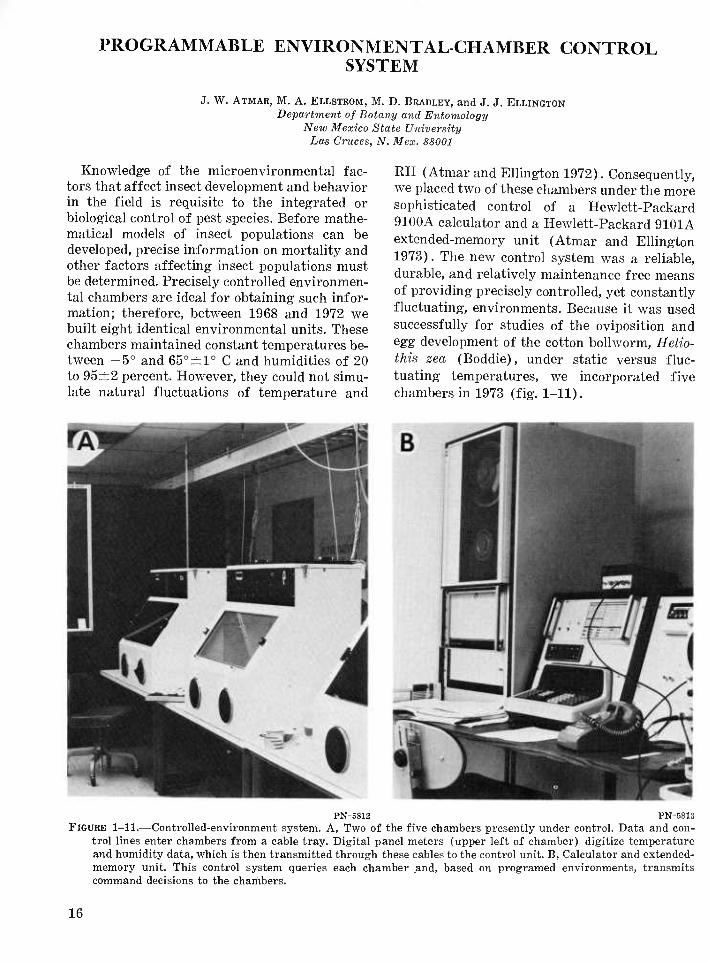
Knowledge of the microenvironmental fac- tors that affect insect development and behavior in the field is requisite to the integrated or biological control of pest species. Before mathe- matical models of insect populations can be developed, precise information on mortality and other factors affecting insect populations must be determined. Precisely controlled environmen- tal chambers are ideal for obtaining such infor- mation; therefore, between 1968 and 1972 we built eight identical environmental units. These chambers maintained constant temperatures be- tween -5° and 65°±1° C and humidities of 20 to 95±2 percent. However, they could not simu- late natural fluctuations of temperature and
RH (Atmar and Ellington 1972). Consequently, we placed two of these chambers under the more sophisticated control of a Hewlett-Packard 9100A calculator and a Hewlett-Packard 9101A extended-memory unit (Atmar and Ellington 1973). The new control system was a reliable, durable, and relatively maintenance free means of providing precisely controlled, yet constantly fluctuating, environments. Because it was used successfully for studies of the oviposition and egg development of the cotton boUworm, Helio- this zea (Boddie), under static versus fluc- tuating temperatures, we incorporated five chambers in 1973 (fig. 1-11).
PN-5812 PN-6813 FIGURE 1-11.—Controlled-environment system. A, Two of the five chambers presently under control. Data and con-
trol lines enter chambers from a cable tray. Digital panel meters (upper left of chamber) digitize temperature and humidity data, which is then transmitted through these cables to the control unit. B, Calculator and extended- memory unit. This control system queries each chamber .and, based on programed environments, transmits command decisions to the chambers.
16

SPECIFICATIONS
General description.—The chamber control system is digital and is built around a Hewlett- Packard 9100B programmable calculator and a Hewlett-Packard 9101A extended-memory unit. The 9100B was selected over the 9100A (used in our first system) because of a timing error in the design of the 9100A. The complete system is shown schematically in figure 1-12.
A central data-control bus links the five cham- bers in a parallel configuration to the control system. Since the 9100B calculator employs dis- crete-component logic and the remainder of the system is built around transitor-transitor logic (TTL), logic-level converters must be used to process the incoming and outgoing signals for system compatibility. The basic control scheme consists of two phases (or scans) of each of the five chambers. During the first phase, the controller sequentially addresses each chamber, requests temperature data from the chamber, and then compares the received information with the desired programed environment. The controller then transmits the appropriate com- mand signal (temperature on or temperature off). Once the first phase has been completed, the second phase is initiated. The second phase is an RH scan and performs essentially the same tasks, turning the humidification circuit on or off. The entire procedure of addressing the chamber, receiving environmental informa- tion, and making and transmitting a control decision requires 2 seconds per chamber. Thus, 20 seconds are required to make a complete scan of temperature and RH in all five cham- bers. At the end of the 20-s period, the scanning begins again.
Sensor data,—The temperature sensors are Yellow Spring Instruments 44001 thermistors. These thermistors have a 100-ohm resistance at 25° C and are guaranteed to be interchangeable at a 99 percent accuracy level. Thermistors were chosen over thermocouples as the temper- ature sensors for two reasons: (1) The output voltages are in millivolts rather than micro- volts; therefore, noise abatement is simpler with thermistors. (2) Although the accuracy of a themistor is generally less than that of a thermocouple, the 44001 thermistors are guar- anteed to be accurate within ±0.3° C (±0.1° C typical), which is satisfactory for system use.
Calibration charts supplied by Yellow Spring
CENTRAL DATA BUS CHAMBER ADDRESS^
FORMAT COMMAND
INTERCEPTOR
EXT CLOCK
LOGIC LEVEL
CONVERTERS
HP9I00B CALCULATOR
HP 9101 A EXTENDED MEMORY
CONTROLLER LOGIC
ADDRESS DECODER
HP 3431 DIGITAL PANEL METER
SENSOR SELECT
.REACTOR ON/OFF^
■M
id
_SENSORS J
ENVIRONMENTAL CHAMBER
FIGURE 1-12.—Block diagram of controlled-environment system, showing the interfacing with one of the five chambers.
Instruments are used to convert the sensor volt- ages into degrees Fahrenheit or Celsius (as preferred by the operator). Because it is im- practical to store such charts in the calculator, the data are converted to formulas for storage in the memory unit. A second-order polynomial equation gives the best fit to the thermistor data. The polynomials are obtained by a non- linear regression (least-squares parabola) pro- cedure. These curves provide a fit of ±0.05° C for maximum error over a span of 10° C and ±0.1° C for maximum error over a span of 20° C. The calculator determines the correct tem- perature-conversion formula by a conditional branching routine.
The RH in the chambers is determined by a Thunder Scientific (model BR-101) Brady array. The Brady array, a solid-state sensor, can measure from less than 5 to 100 percent RH and has a guaranteed accuracy of ±4 per- cent (±2 percent RH or better typical) and a resolution better than 0.1 percent. Each Brady array is used in conjunction with a Thunder Scientific model SC-1020M signal-conditioning module, which provides an analog output volt- age proportional to the RH. Since the sensors have slightly different characteristics. Thunder Scientific supplies precise calibration data with
17
263-699 O - 78 - 4

each instrument. These data are used to gen- erate second-order polynomial equations in identically the same manner as that used for thermistors. RH sensor calibration is frequent- ly checked by comparison to a Thunder Scien- tific model 4A-1 secondary-transfer standard psychrometer, the accuracy of which is verified by the National Bureau of Standards.
CONSTRUCTION AND OPERATION Detailed machine description.—The design of
the Hewlett-Packard 9100B makes its connec- tion to the environmental chambers easy. All signal and control lines are on a rear terminal connecter; hence, no internal modification of either the calculator or the extended memory unit is necessary. Three circuit boards were de- signed and constructed to provide the 9100B with a means of communicating with the cham- bers. In addition, control logic boards were con- structed and installed, one in each of the five chambers (detailed schematics are available from the authors).
Interface amplifier and logic level convert- er.—This board receives timing and control sig- nals from the calculator; the signals address and command the individual chambers. Each of the 11 signals received on this board is con- verted from the logic levels used in the 9100B (—15 V==true) to TTL (+5 V=true) levels.
FORMAT command interceptor.—The FOR- MAT (FMT) instruction generated by the cal- culator is used exclusively to address and control the chambers. The logic on this board decodes the FMT instructions from the calcu- lator and insures proper timing of the com- mands. The FMT instructions serve the following purposes (FMT/a=logical 1, or true; FMT/a=logical 0, or false) :
Addressing chamber , , , instructions : Addressed chambers :
FMT/a, FMT/b, FMT/c a (001) FMT/a, FMT/b, FMT/c ß (010) FMT/a, FMT/b, FMT/c y (Oil) FMT/a, FMT/b, FMT/c S (100) FMT/a, FMT/b, FMT/c s (101)
Control functions and instructions: Action:
GO signal, FMT/d •• Enables chamber addressed to respond to commands.
ON signal, FMT/e • • • Turns proper reactor con- trol on.
OFF signal, FMT/f • • Turns proper reactor con- trol off.
SENSOR SELECT, FMT/8 FMT/8 temperature (heat-
er) ; FMT/8 relative hu- midity.
CLEAR, FMT/9 Reset addresses and control functions.
Input/output control.—The FMT commands from the FMT interceptor board are outputted to the chambers through a series of output in- terfacing latches. Because the FMT commands are generated serially in the calculator, these latches allovv^ the commands to be simultaneous- ly dumped onto the data bus in parallel. This board also contains the logic and timing neces- sary to receive the digitized temperature and humidity data from the chambers and relay them to the calculator by a series of field-effect transitors that convert the digitized data from TTL levels to levels compatible with the Hewlett-Packard 9100B.
Chamber control logic.—These boards com- municate with the calculator through the cen- tral-data bus and the input/output control board. When a chamber receives and decodes the appropriate address (accompanied by a GO signal) the Hewlett-Packard 3431A digital panel meter (DPM) is put in a hold condition. Data from the DPM are then located serially into a parallel data-output buffer. After the buffer is loaded, the buffer lines are enabled, and the digitized sensor data are transmitted to the calculator. The sensor select (FMT/8) com- mand is transmitted to the addressed chamber before the data transmission, and the appro- priate sensor data are then read into the calcu- lator. When a FMT/e (ON) or a FMT/f (OFF) signal is returned, reactor action based on the state of the FMT/8 (TEMP/RH) com- mand is effected. These reaction commands are stored in reactor storage (RS) latches to main- tain the proper reactor actions until the cham- ber is queried again on the next cycle. The outputs of the RS latches drive solid-state re- lays, which in turn control the temperature and RH devices.
PROGRAMING Programing associated with the control sys-
tem has been modularized into subroutines. The main program acts as a steering and synchroniz- ing program, calling for each subroutine in se- quence (fig. 1-13). Thus, the main program controls the sequential addressing of the cham-
18
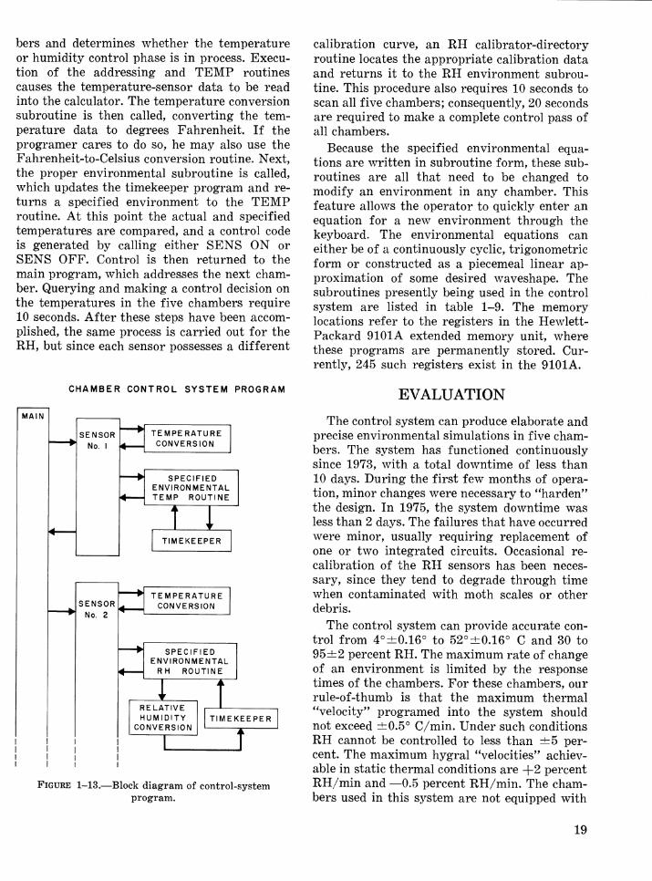
bers and determines whether the temperature or humidity control phase is in process. Execu- tion of the addressing and TEMP routines causes the temperature-sensor data to be read into the calculator. The temperature conversion subroutine is then called, converting the tem- perature data to degrees Fahrenheit. If the programer cares to do so, he may also use the Fahrenheit-to-Celsius conversion routine. Next, the proper environmental subroutine is called, which updates the timekeeper program and re- turns a specified environment to the TEMP routine. At this point the actual and specified temperatures are compared, and a control code is generated by calling either SENS ON or SENS OFF. Control is then returned to the main program, which addresses the next cham- ber. Querying and making a control decision on the temperatures in the five chambers require 10 seconds. After these steps have been accom- plished, the same process is carried out for the RH, but since each sensor possesses a different
calibration curve, an RH calibrator-directory routine locates the appropriate calibration data and returns it to the RH environment subrou- tine. This procedure also requires 10 seconds to scan all five chambers; consequently, 20 seconds are required to make a complete control pass of all chambers.
Because the specified environmental equa- tions are written in subroutine form, these sub- routines are all that need to be changed to modify an environment in any chamber. This feature allows the operator to quickly enter an equation for a new environment through the keyboard. The environmental equations can either be of a continuously cyclic, trigonometric form or constructed as a piecemeal linear ap- proximation of some desired waveshape. The subroutines presently being used in the control system are listed in table 1-9. The memory locations refer to the registers in the Hewlett- Packard 9101A extended memory unit, where these programs are permanently stored. Cur- rently, 245 such registers exist in the 9101A.
CHAMBER CONTROL SYSTEM PROGRAM
MAIN
SENSOR No. I
SENSOR No. 2
TEMPERATURE CONVERSION
SPECIFIED ENVIRONMENTAL TEMP ROUTINE
TIMEKEEPER
TEMPERATURE CONVERSION
SPECIFIED ENVIRONMENTAL
RH ROUTINE
RELATIVE HUMIDITY
CONVERSION TIMEKEEPER
I
FIGURE 1-13.—Block diagram of control-system program.
EVALUATION
The control system can produce elaborate and precise environmental simulations in five cham- bers. The system has functioned continuously since 1973, with a total downtime of less than 10 days. During the first few months of opera- tion, minor changes were necessary to "harden'' the design. In 1975, the system downtime was less than 2 days. The failures that have occurred were minor, usually requiring replacement of one or two integrated circuits. Occasional re- calibration of the RH sensors has been neces- sary, since they tend to degrade through time when contaminated with moth scales or other debris.
The control system can provide accurate con- trol from 4°±0.16° to 52°±0.16° C and 30 to 95±2 percent RH. The maximum rate of change of an environment is limited by the response times of the chambers. For these chambers, our rule-of-thumb is that the maximum thermal 'Velocity" programed into the system should not exceed ±0.5° C/min. Under such conditions RH cannot be controlled to less than ±5 per- cent. The maximum hygral "velocities" achiev- able in static thermal conditions are +2 percent RH/min and —0.5 percent RH/min. The cham- bers used in this system are not equipped with
19

TABLE 1-9.—Programs used to control five environmental chambers
[Programs 11-15 address the appropriate chambers; programs 21-25 and 31-35 specify the desired environ- mental regimes; and programs 4-6 and 70-75 provide the appropriate temperature and RH conversions]
Program No. Program names Memory location
1 2 3 4 5 6
11 12 13 14 15
21 22 23 24 25
31 32 33 34 35
40 41 50
70 71 72 73 74 75
MAIN 0-9 TIMEKEEPER 10-11 CLOCK (H,MIN,S DISPLAY) •• 12-16 TEMP 1 17-21 TEMP 2 22-24 TEMP 3 25-27
a ADDRESS 28 ^ADDRESS 29 y ADDRESS 30 S ADDRESS 31 e ADDRESS 32
a DESIRED TEMP ENV 33-34 ß DESIRED TEMP ENV 35-36 y DESIRED TEMP ENV 37-38 8 DESIRED TEMP ENV 39-40 £ DESIRED TEMP ENV 41-42
a DESIRED RH ENV 43-44 ß DESIRED RH ENV 45-46 y DESIRED RH ENV 47-48 8 DESIRED RH ENV 49-50 e DESIRED RH ENV 51-52
SENS ON 53 SENS OFF 54 °F-to-°C CONVERSION 55
RH CAL DIRECTOR 56-60 a RH CAL 51-65 ß RH CAL 66-70 y RH CAL 71-75 8 RH CAL 76-80 e RH CAL 81-85
a dehumidification system because of our arid climate. The root-mean-square absolute system error (worst case) is ±0.4° C. The normal ab- solute error incurred in the system is less than ±0.2° C.
Examples of environmental simulations that the controller system has produced under actual experimental conditions are depicted in figure 1-14. The graph was recorded on a calibrated Bendix hygrothermograph.
A digital-system design was chosen over ana- log (or proportional) control for several rea- sons. The primary criterion is that there is no loss in measurement accuracy once a data word has been formed. Similarly, there is little need
PN-5814
FIGURE 1-14.—Graph showing a thermal environment of 26.7°±11.1° C (converted from degrees Fahren- heit) and RH of 85 percent. In a fluctuating en- vironment in which 22.2° C are traversed, the humidity control degrades to ±4 percent RH.
for accurate reference sources in a digital sys- tem, since the amount of analog sensing and amplifying equipment has been minimized. Electrical noise, cable losses, and thermal drift are likewise minimized. The major disadvan- tage of any digital system is that the maximum resolution is set once the data word size is se- lected. In the chamber control system, the reso- lution is one part in a thousand (three digits) or approximately ±0.1° C with the thermistors and ±0.5 percent RH with the humidity sensors presently in use. Hence, the major sources of error in the control system are out-of-calibra- tion sensors, thermal drift in the digitizer, and approximation errors in the linearizing operation.
The versatility of the control system allows a multiplicity of independently varying environ- ments to run concurrently in each of the cham- bers. Although only five chambers are on line now, the remaining three could be added to the system with only minor program modifications. The addition of these chambers would increase the complete-control cycle time from 20 to 32 seconds, thereby reducing control accuracy. On the other hand, if only one or two environments are to be simulated, the unneeded chambers can simply be turned off. The control system con-
20

tinues to address all the chambers, but only those on line are controlled, which results in considerable energy savings as well as an abate- ment of mechanical wear on the compressors, fans, and heaters.
The Hewlett-Packard 9100B and 9101A pos- sess nonvolatile memory; thus, should a power failure occur, the system will automatically re- start once the power is restored. The program simply resumes execution at the point of power failure. If the power has been off for an ex-
tended period, the clock must be reset or a noticeable time-control phase shift will occur in the chambers.
All the logic circuitry used in the calculator- chamber interface is readily available from electronic parts distributors. Wire-wrap con- struction techniques were used exclusively for ease in assembling the boards containing inte- grated circuits, although printed circuit boards could have been employed. Discrete devices were largely mounted on vector boards.
21


SECTION 2 ROOM-SIZE UNITS
23


ROOM-SIZE SYSTEM FOR REARING LEPIDOPTERA
R. L. BURTON Science and Education Administration
Oklahoma State University Stillwater, Okla, 7U07U
The single-room design is simple, compact, efficient, and practically complete (fig. 2-1). The equipment and furniture are arranged with respect to related tasks and manipulation of various stages of the insects. Only the design is unique; the equipment, techniques, and state of the art are standard. The facility is used for rearing small numbers of the corn earworm, Heliothis zea (Boddie), fall armyworm, Spod- optera frugiperda (J. E. Smith), and related species.
SPECIFICATIONS
The convenient high center-island workbench (A) is especially suited for weighing, diet mix- ing, and similar tasks. Diet ingredients are stored beneath the workbench and in the refrig- erator (L) and freezer (M). A small gas range (B) is included for heating agar solutions etc. The clean workbench (C) provides an area for dispensing diet, infesting larval-rearing con- tainers, and performing associated aseptic pro-
CLEAN WORKBENCH
D EGG a LARVAL
STORAGE LARVAL STORAGE
SAFETY HOOD
-7.62 m-#-
WALL CASES
LARGE SINK AREA
N
0 3-SECTION SINK
CENTER-ISLAND STANDING WORKBENCH
0,91 m
3.65 m
K SITTING WORKBENCH (window)
M FREEZER
L REFRIGERATOR
K SITTING WORKBENCH (window)
EMERGENCE CAGES
OVIPOSITION CAGES
EGG COLLECTION
FIGURE 2-1.—Floor plan for room-size facility.
25
263-699 O - 78 - 5

cedures. In addition, this bench upgrades the entire area in terms of airborne particulate matter. A microbiological safety hood (F) or similar equipment is necessary if pupae are col- lected from containers or if other potentially contaminated materials are used (table 2-1). A small self-contained countertop autoclave (G) satisfies most of the sterilization requirements. A vacuum and gas supply, electrical outlets on 46-cm centers, fluorescent lighting banks, and proper heating and air-conditioning systems are standard requirements.
OPERATION AND EVALUATION The larvae are housed in a closed cabinet (D)
maintained at room temperature but with greater than 90 percent RH created by moisture that escapes from the rearing containers. Lar- vae are allowed to develop under these condi- tions for 8 to 10 days; then they are moved to a storage chamber (E) having less than 40 per- cent RH until development is completed. This regime is suitable for insects such as H. zea but is unfavorable for microbial growth.
Emergence and oviposition cages (I) require more space than other rearing components. Therefore, care should be taken to select suf- ficiently large holding facilities. A range of 10° to 38° C and 60 to 95 percent RH should meet most environmental requirements. The compo- nents recommended here (I, D, and E) serve only as examples, but whatever the choice, a dependable high-temperature safety cutout and exhaust fan are recommended.
Special equipment (J) is required to remove airborne wing scales when moths are handled. When this device is used, air is rapidly removed
TABLE 2-1.—Major components for room-size system for rearing Lepidoptera
Reference letter Component
(fig. 2-1)
E,I Environmental chamber, reach-in (Forma Scientific models; or humidified
Bry-Air A-0.5-B) F Safety-hood workbench, microbiological
(Scientific Products L5229; with base unit, Hamilton 6P73; 6P5)
G Autoclave, instrument-size, self-contained (Castle Sybron999-C)
H Counter-high base unit (Hamilton 2P554)
from the work surface, pulled through foam furnace filters, and pushed back into the lab. Filters should be located conveniently so that they can be cleaned with a small vacuum cleaner.
Simplicity is an important aspect of rearing, especially when handling small colonies of in- sects for research needs. The objective is to raise the desired number of insects as easily, quickly, and inexpensively as possible. There- fore, techniques, equipment, and facilities should be changed as necessary in order to sim- plify the rearing process. Generally, all our current rearing operations are accomplished in this scheme. However, implementation of this facility, as designed, would make operations more efficient by integrating all the phases of rearing into one area. A rearing system of this type has proven effective for the production of small quantities of insects for several years.
ROOM FOR REARING HOUSE FLIES AND STABLE FLIES
R. S. PATTERSON Insects Affecting Man Research Laboratory
Science and Education Administration Gainesville, Fla. 3260JÍ
This facility (fig 2-2) provides the environ- mental conditions necessary for large-scale rearing of house flies. Musca domestica (L.). It is a large room subdivided according to rear- ing operations and has specialized equipment. With minimum rearrangement, it has also been used to rear stable flies, Stomoxys calcitrans (L.), and anopheline mosquitoes.
SPECIFICATIONS AND CONSTRUCTION
The 6.1- by 4.6-m room is part of a concrete- block building that houses several other insect colonies. Individual thermostats regulate the temperature of these rooms at 26°±2° C by actuating a central heating and air-conditioning
26

6.1m
00 -4.6m
FIGURE 2-2.—Diagram of fly-rearing room. 1, Fly-cage racks. 2, Larvae development rack. 3, Diet-mixing table. 4, Larval-medium containers. 5, Water sup- ply. 6, Pupae dryer. 7, Adult food containers.
system. Humidity (60 to 65 percent controlled by a room humidistat) is provided by industrial humidifiers suspended from the ceilings. In the fly-rearing room, a 13-h photophase is provided by two banks of fluorescent tubes in ceiling fix- tures. A 25-cm-diameter exhaust fan, mounted in the outside wall above the cage racks (1), removes excessive ammonia fumes.
OPERATION
The main section (I) of the fly-rearing room is devoted to rearing immature stages. Dry larval medium is stored in containers (4) under the mixing table (3), which is high enough for a technician to mix the diet on while standing. Tapwater (5) is added to each tray during mix- ing, and all trays on a given day are prepared simultaneously before being infested with eggs. Finally, the provisioned trays are transferred to a 1.2- by 1.8- by 4.1-m rack constructed of 7.6- by 3.8-cm slotted metal framing (2). The rack is divided into eight 48-cm-wide compart- ments, and each compartment is further sub- divided into 16 sections (fig. 2-3). Opposing edges of the framing support the rims of the
PN-B815
FIGURE 2-3.—Rack for holding trays of developing larvae.
trays. When the entire rack is in production, a fan is placed at one end to provide air circula- tion for removal of heat generated by the fer- menting medium. Otherwise, the trays are placed in alternate sections.
After 7 days, the larvae normally migrate to the surface of the medium to pupate. The re- sulting mixture of larvae, pupae, and diet is scraped from the surface and washed to harvest the pupae. Pupae are then dried in the blower (see item 6, fig. 2-2). Typically, 16 trays are established during a 5-day work week, but the rack can hold 128 trays and yield 2.5 to 3 million pupae per rearing cycle.
Section II (fig. 2-2) is used to house the adult flies, and it is partitioned from the main section by a wooden frame covered with 20- mesh screen. Initially, about 5,000 pupae are placed in each provisioned cage. These cages are located on one of four shelves per rack (1), and food for the adults is stored in adjacent containers (7).
EVALUATION
Fly rearing has been accomplished in these or similar rooms since 1965. Periodically, changes have been incorporated to improve ef- ficiency and convenience. The present system was completed in 1974, and it provides for an average production of more than 300,000 pupae per 6 hours of labor.
27
MODULAR ROOMS FOR MODIFICATION OF AMBIENT LABORATORY ENVIRONMENTS
N. C. LEPPLA and S. L. CARLYLE Insect Attractants, Behavior, and Basic Biology Research Laboratory
Science and Education Administration P.O. Box U565, Gainesville, Fla. 3260J,
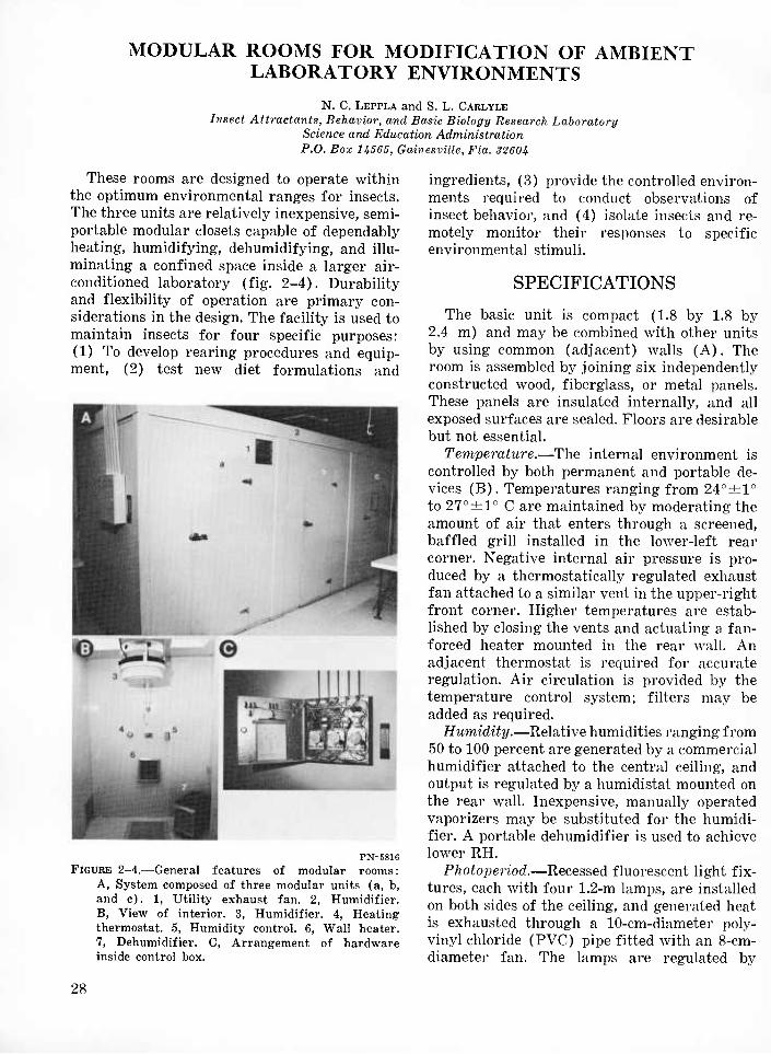
These rooms are designed to operate within the optimum environmental ranges for insects. The three units are relatively inexpensive, semi- portable modular closets capable of dependably heating, humidifying, dehumidifying, and illu- minating a confined space inside a larger air- conditioned laboratory (fig. 2-4). Durability and flexibility of operation are primary con- siderations in the design. The facility is used to maintain insects for four specific purposes: (1) To develop rearing procedures and equip- ment, (2) test new diet formulations and
PN-B816 FIGURE 2-4.—General features of modular rooms:
A, System composed of three modular units (a, b, and c). 1, Utility exhaust fan. 2, Humidifier. B, View of interior. 3, Humidifier. 4, Heating thermostat. 5, Humidity control. 6, Wall heater. 7, Dehumidifier. C, Arrangement of hardware inside control box.
ingredients, (3) provide the controlled environ- ments required to conduct observations of insect behavior, and (4) isolate insects and re- motely monitor their responses to specific environmental stimuli.
SPECIFICATIONS
The basic unit is compact (1.8 by 1.8 by 2.4 m) and may be combined with other units by using common (adjacent) walls (A). The room is assembled by joining six independently constructed wood, fiberglass, or metal panels. These panels are insulated internally, and all exposed surfaces are sealed. Floors are desirable but not essential.
Temperature.—The internal environment is controlled by both permanent and portable de- vices (B). Temperatures ranging from 24°±1° to 27° ±1° C are maintained by moderating the amount of air that enters through a screened, baffled grill installed in the lower-left i-ear corner. Negative internal air pressure is pro- duced by a thermostatically regulated exhaust fan attached to a similar vent in the upper-right front corner. Higher temperatures are estab- lished by closing the vents and actuating a fan- forced heater mounted in the rear wall. An adjacent thermostat is required for accurate regulation. Air circulation is provided by the temperature control system; filters may be added as required.
Humidity.—Relative humidities ranging from 50 to 100 percent are generated by a commercial humidifier attached to the central ceiling, and output is regulated by a humidistat mounted on the rear wall. Inexpensive, manually operated vaporizers may be substituted for the humidi- fier. A portable dehumidifier is used to achieve lower RH.
Photoperiod.—Recessed fluorescent light fix- tures, each with four 1.2-m lamps, are installed on both sides of the ceiling, and generated heat is exhausted through a 10-cm-diameter poly- vinyl chloride (PVC) pipe fitted with an 8-cm- diameter fan. The lamps are regulated by
28

TABLE 2-2.—Major components for modular room
Reference No. (fig. 2-4) Component
1 Utility exhaust fan, automatic shutters, 25-cm (Dayton 3M252)
2 Humidifier, 19-1 (Northern Electric E37554,
style No. 45) 3 Humidifier
(Walton Laboratories SFIO) 4 Thermostat, heating, 4.4° to 32.2° C
(Honeywell T87F) 5 Humidity control, 20% to 80% RH
(Honeywell H600A 1014-1) 6 Wall heater, fan-forced, 1,000-W
(Dayton 2E153) 7 Dehumidifier, 4-1/d
(Westinghouse 5 H422) — Heating-ventilating control,
-1.1° to 37.8° C (Honeywell T631C11031)
— Light timer switch, 24-h (Intermatic T-101)
— Service door hinge, narrow-flange flush- mount, 16-cm (McMaster-Carr 1276A17)
— Snap-action refrigerator latch (McMaster-Carr 1266 B2)
external 24-h timers contained in the control box, which also contains the humidifier relays, heater relays, and heater-relay transformers (C). Auxiliary incandescent lights may be pow- ered from four ceiling and rear-wall electrical receptacles. Rheostats are used when gradual light transitions are desired.
CONSTRUCTION
The 1.7- by 1.8-m floor panel, 1.7- by 2.4-m wall panels, and 1.7- by 1.9-m ceiling panel are constructed by first assembling suitable wood frames of 5- by 5-cm stock (fig. 2-5). Internal braces are prearranged to provide support for doors, windows, and specialized equipment to be mounted in or on the walls. One side of each frame is then covered with an external building material (tempered Masonite, plywood, fiber- glass, metal, etc.), trimmed, inverted, and lined with fiberglass insulation. The open side is finally sealed with another piece of outside cov- ering. To erect the room, 15-cm-long lag bolts are used to secure the front and rear panels to the floor panel and the adjoining sides to each
FIGURE 2-5.—Diagram of specific features of modular room.
other. The ceiling is lowered and secured from above. The fixtures, instruments, and electrical wiring are installed last (table 2-2). Each unit is then sealed with calking compound and trimmed with molding.
OPERATION AND EVALUATION These rooms are a useful size and may be
employed independently or in series for short- term research projects. For specific studies, minor alterations are performed, and portable accessories, such as dehumidifiers, liorht fix- tures, and shelves, are added. Also, auxiliary filtration and air-circulation equipment is oc- casionally used to insure a cleaner, more uni- form environment. The internal environment may be maintained within a temperature range of ±1° C and RH of ±4 percent, but condi- tions usually fluctuate at about twice these magnitudes.
The three prototype units have been in con- tinuous operation since 1974 without requiring major repair or reconditioning. Routine main- tenance must be performed to clean the humidi- stats, humidifiers, and electric fans. Lamps must also be tested and replaced periodically. However, after modification, calibration, and stabilization, only weekly maintenance is re- quired. The major limitation of the system is its lack of cooling capability, but this may be added when necessary. Recording instrumenta- tion would eliminate manual monitoring and
29

provide for automatically limiting maximum inexpensive system (about $500 per room) has and minimum temperatures. Thus, the simple, proven to be flexible and dependable.
CONTROLLED-ENVIRONMENT ROOM
M. C. HAMPSON
Cavada Department of Agriculture Research Station P.O. Box 7098
St. .Johns W., Newfoundland, Canada, AIE 3Y,<¡
The room is designed for rearing potato and tomato seedlings in pots and flats of infected soil (fig. 2-6). The principle of operation is to exhaust heated air and replace it with cooler outside air that is primarily directed across lights. Simplicity of operation and infrequent technical maintenance are features of the de- sign. The room is used to grow seedlings in isolation from normal seasonal influences, and it allows (1) an increase in the number of gen- erations undergoing experimentation through-
PN-B817 FIGURE 2-6.—View of controlled-environment room,
through doorway to northeast corner. Note stair- well location and position of concealed baffles (b and c) in plenum.
out the year, (2) control of the quality of the environment so that comparative measurements can be made of differences in infectivity and susceptibility, and (3) an evaluation of the in- fluences of varying climatic features such as light, temperature, and water on infection.
SPECIFICATIONS
One wall of an existing rectangular room is partitioned with plywood panels and a doorway. The floor to ceiling height (fig. 2-7) is 2.8 m, and the wall to wall measurements are 3.8 m (east to west) and 3.0 m (north to south). Peg- board is fitted onto the east and west walls to provide two 30-cm-deep plenums. Inside, the room is 2.7 m high, 3.1 m long, and 2.8 m wide.
Airflow.—A centrifugal blower is housed in a duct above the ceiling (fig. 2-8). Air, forced through the duct to the east plenum, flows along the plenum and through the pegboard wall. The major airflow remains in the upper part of the room and removes heated air through the ex-
ORKHNAL STRUCTUtll
NIW STRUCTURI
MGROAtD AIR FLOW
FIGURE 2-7.—Diagram of controlled-environment room. (Note baffles a, b, and c and duct r.)
50

haust (west plenum). Air circulates, or is di- verted through an exhaust duct, in accord with the room temperature; a sensor actuates the damper motor. Spaces behind the major plenum baffle (b) allow some air to flow down and into the lower part of the room, even though this baffle concentrates airflow in the upper part of the room and across the light arrays. The room design accommodates a stair well in the northeast corner that required the construc- tion of another baffle (see item c, figs. 2-6 and 2-7). This feature results in a clockwise airflow around the room. Air is exhausted through the west plenum and along the north wall. This baffle (c) causes a rapid airstream that effectively mixes the room air.
Temperature,—Heat is normally supplied by lights and ballasts. Air is kept circulating until the temperature rises above maximum. A sen- sor located in the airflow of the southwest corner triggers the damper in the duct to divert the recirculated air and admit cooler outside air. To prevent the temperature from falling below minimum, a pair of 1-kW heaters are placed in the air duct behind the fan; they are operated by individual internal thermostats placed on the southwest wall. If there is a loss in positive pressure, feather-vaned cutouts in the air duct prevent the room from overheating. The damper thermostat is placed outside the room for easy manipulation.
Relative humidity,—A commercial humidi- fier, which is cleaned annually, hangs from the ceiling above the doorway. An internal humidistat is mounted on the west wall.
Lighting,—Light is supplied from sixteen 2.4-m fluorescent tubes and incandescent lamps.
eight on the west side and eight on the east side. External 24-h timers regulate the photoperiod. A pair of auxiliary incandescent lamps are mounted in the ceiling. The height of the light fixtures can be adjusted by cranking a pulley system. Normally, they are adjusted to provide about 12,000 Im/m- at the bench surface. The north and south walls are lined with aluminum foil to compensate for some decline in light intensity at the ends of the light arrays.
CONSTRUCTION
The floor is cement, and the wall panels are hung on 7.5- by 7.5-cm-stock wooden frames. The pegboard is moisture resistant and is 6.3 mm thick, with holes spaced 2.5 cm apart. The walls and ceiling are prepared with vapor barriers and are lined with 7.5-cm-thick fiber- glass. The inside top of each plenum contains a duct that opens into a larger duct; this duct crosses the ceiling in the room above. This large duct is 45 cm- and is divided into two more ducts at the west end. The damper is arranged to seal off both of these ducts for normal air circulation. When the damper is opened fully, flow from the exhaust plenum into the top duct is cut off. This effect is accomplished by a damper that rests on a baffle located across the lower part of the top duct. The wiring is in- stalled before the walls are secured in place. The intake and exhaust ports are made of ply- wood, suitably capped and screened. The fix- tures and instruments are installed last (table 2-3).
TABLE 2-3.—Major components for controlled- environment room (figs, 2-6, 2-7)
FIGURE 2-8.—Diagram of east plenum, showing baffle (a, b, and c) placement in relation to stair-well casing in northeast corner of room.
Fluorescent lamps, 2.4-m, 12-CW-VHO-135 (Sylvania FR96/72T)
Humidifier (Walton Laboratories SW5)
Blower, 0.25-kW, 1,725-r/min (Delhi GIO)
Heater, DHF, high- and low-voltage regulation, 1-kW (P. M. Wright models)
Humidistat, 20% to 80% RH (Honeywell H44B-1004-1)
Light timer switch, 24-h (General Electric T5A-47)
Temperature controller, 24-V (Honeywell T991A, series 90)
Airflow cutout switch, 2-A (Rotron, type 1350)
31

OPERATION AND EVALUATION
Tlie internal environment remains remark- ably steady if the external temperature does not become greater than the internal temperature. If the temperature of the incoming air needs to be altered, a refrigeration coil can be installed in the available space in duct r (fig. 2-7). Tem- perature differentials across the room are not more than 2^ C; thus, soil temperatures remain
uniform. During 3 years of continuous opera- tion (1972-75), only the blower pulley had been replaced. Additional water and electric outlets allow extra equipment to be included without the need for altering the room operation. We are in the process of establishing an automatic watering system. There is a reasonable degree of flexibility in the operation, dependable function- ing of the fixtures, and accurate maintenance of temperature, RH, and light.
FACILITY FOR CULTURING MICROHYMENOPTERAN PUPAL PARASITOIDS
p. B. MORGAN and R. S. PATTERSON Ivsects Affecting Man Research Laboratory
Science and Education Administration P.O. Box U565, Gainesville, Fla. 32G0!t
This walk-in facility (fig. 2-9) was designed and built with the capability for independent regulation of temperature, RH, and illumina- tion. However, at the present time, temperature and humidity control are provided by an ad- jacent laboratory. Although this facility has been used specifically for conducting research on the microhymenopteran pupal parasitoid Spalangia endius Walker, it could be adapted to a variety of similar research projects.
SPECIFICATIONS
The facility is a 2.1- by 1.3- by 6.0-m room divided into two equal sections by a partition and is located in a 6.6- by 4.6- by 3.6-m labora- tory (fig. 2-10). The back and end walls and floor of each section (9) serve the same pur- poses. The doors, ceiling, front wall, and parti- tion are constructed of 0.95-cm-thick plywood paneling. A 0.3- by 0.3-m window (11) in each section is covered with double 0.67-cm thick- nesses of clear plastic separated by a 5-cm air- space, which allows external visual monitoring of the temperature and RH. Each section also has a separate 0.6- by 1.9-m entrance (7).
Teviperature.—Temperatures ranging from 27.7° to 28.8° C are maintained in each section by actuating a supplementary portable, fan- forced heating unit. If the temperature exceeds 28.8° C, a thermostatically controlled fan on the roof of each section (8) provides cooler air. If the outer laboratory (10) temperature ex- ceeds 28.8° C, an emergency switch shuts off all heat; a similar device is located in each sec-
#■
PN~5818
FIGURE 2-9.—Facility for culturing microhymenopteran pupal parasitoids. A, External appearance of two- section facility. B, View of interior of one section. 1, Emergency cut-off switch. 2, Portable fan-forced heating unit. 3, Electric black-light grid. 4, Air- circulation fan. 5, Window covered with clear plastic. 6, Hydrothei-mograph. 7, Cartons of parasitized house fly pupae.
32

TABLE 2-4.—Major components for facility for culturing microhymenopteran pupal para- sitoids
Reference No. (fig. 2-9)
Component
FIGURE 2-10.—Diagram of specific features of facility. I, Entrance to laboratory. 2, Work bench with sink. 3, Hallway. 4, Laboratory maintenance area. 5, Shelves. 6, Bench. 7, Entrance to walk-in facility. 8, Thermostatically controlled fan located on roof of each section. 9, Walk-in facility. 10, Laboratory. II, Windows in walk-in facility.
tion. Air circulation is provided by continuously operating fans.
Humidity,—Relative humidities ranging from 60 to 70 percent are maintained by two com- mercial humidifiers attached to the ceiling of the laboratory.
Lighting,—A fluorescent light fixture at- tached to the ceiling of each section is regulated by a switch mounted on the outside wall near the entrance. If various photoperiods are needed, the light switches are replaced by 24-h timers. A black-light electrical grid trap is also present to attract and kill any loose parasitoids.
3 Black-light electric fly grid (Gilbert International models)
4 Circulating fan, hassock-type, 1,500-1/s (Dayton 4C509)
6 Hygrothermograph (Belfort Instruments 5-594)
— Heating-ventilating control, -1.1° to 37.8° C (Honeywell T631C11031)
— Shaded pole blower, 27-1/s (Dayton 4C448)
CONSTRUCTION
The facility is constructed by first assembling a wood frame of 5- by 10-cm stock. Internal braces are added to provide support for doors and specialized equipment to be mounted on the walls. The exterior and interior surfaces of the ceiling and front walls are covered with 0.95- cm-thick plywood paneling. The frame separat- ing the exterior and interior paneling provides a 5-cm-insulating airspace. The doors of each section, as well as the partition that separates the sections, are constructed in the same man- ner. Fixtures and electrical wiring are installed last (table 2-4). Each section is then sealed with calking compound and painted with white latex paint.
OPERATION AND EVALUATION This facility is of useful size, and the sections
may be employed together or independently. Alterations may be made with little effort, and additional equipment, such as humidifiers, de- humidifiers, incandescent lights, air condition- ers, and rheostats, can be added. The facility has been in continuous operation since 1974 without requiring repair or modification. It is used to rear 2,000,000 wasps per week for field studies. The cost was minimal and construction required only 5 man-days.
33
263-699 O - 78 ■

INSECT-REARING ROOMS A. N. KiSHABA
Boyden Entomology Laboratory Science and Education Administration P.O. Box 112, Riverside, Calif. 92502
Rooms of an existing structure were modified to operate within the optimum environmental ranges for rearing insects (fig. 2-11). Reliabil- ity, uniformity of temperature with minimum airflow, and ease of sanitation were of primary concern. The laboratory rooms (A and B) are relatively inexpensive, permanent structures with thermostatically controlled heating and cooling systems and a regulated photoperiod. They provide controlled environments to (1) de- velop insect-rearing procedures, (2) test diet formulations, and (3) maintain insect cultures for research.
SPECIFICATIONS
The basic unit is any moderate-size room in an insulated building. The walls should contain
ROOM A
ROOM B
6
8 15
1 ,
15 15
6 2 F'
15 15
5 cm of Styrofoam or equivalent insulation. Minimum outside-wall exposure and high ceilings are preferred.
Temperature,—The internal environments of the rooms are controlled by thermostatically actuated cooling and heating systems (table 2- 5). Temperatures ranging from 20°±4° to 320-4-40 Q çg^^ j^g maintained. In room A, a 12,000-Btu cooling coil with fan (9) is coupled with the existing 36,000-Btu compressor for the cold room, which is kept at 10° C. Two liquid solenoids (11 and 12), which are matched to the capacity of their respective cooling coils, are installed in the incoming lines. The com- pressor, located outside, is automatically actu- ated on pressure drop by a back-pressure switch. Heat is provided by four screw-in heat- ing elements (14) mounted in front of the cool- ing coil. The heating and cooling units for room B were purchased and installed commercially.
TABLE 2-5.—Major components for insect- rearing rooms
Reference No. (fig. 2-11) Component
FIGURE 2-11.—Floor plan of rooms A and B.
1 Air conditioner, 12,000-Btu/h (Carrier RACK 558K, model 18)
2 Air-conditioner fan coils, with heat package (Carrier 18-BFC-8; heater, Carrier
A5-BFCH) 3 Thermostat, heating/cooling
(Honeywell T872 A 1048-1) 4 Shaded pole blower, 67-1/s
(Dayton 4C005) 7 Time switch, 24-h
(Intermatic T1905) 8 Dehumidifier, Coldspot, 9.5-1/d
(Sears Roebuck 106639200) 9 Cooling coil, 12,000-Btu/h
(Rüssel Coil, model U.C. 65) 10 Hermatic compressor, 36,000-Btu/h
(York 302M12-25; back-pressure switch, York HA 482)
11 Solenoid, liquid, 12,000-Btu/h (Automatic Switch 826 3837)
12 Solenoid, liquid, valve-type (Sparland 125)
14 Heating element, Glo-Coil, 660-W (Eagle 415A)

The compressor (1) is located outside on the ground, and the bare fan coil (2) with heat package is mounted flush with the ceiling and centered on the narrow outside wall.
Humidity.—Adequate moisture is provided by cups of insect larvae on media, and a port- able dehumidifier (8) is actuated to remove any excess.
Photoperiod.—Uncontrolled light enters through the exposed westerly and easterly win- dows of both rooms. Room B also has four 1.2-m, double-lamp, fluorescent light fixtures (6) mounted in the ceiling that are actuated 16 hours per day by a time clock (7).
CONSTRUCTION
Room A is a 2.8- by 3.2- by 2.9-m laboratory alcove in a wood and stucco structure with plas- tered walls; it is closed on one side with the same material. A door fitted with weather stripping (5) is installed to open into the air- conditioned hallway. Originally, room B was a 3.1- by 2.4- by 2.4-m office in a metal Dudley building finished internally with wood and dry- wall. The outside exposed wall and ceiling are insulated with fiberglass. The door is sealed with fiberglass insulation on the outside and drywall on the inside. Also, a piece of galva- nized metal is screwed onto the outer walls. The door opening into the air-conditioned laboratory is sealed with weather stripping. All interior exposed surfaces are painted with washable latex paint. The easterly exposed 1.2- by 0.8-m window is shaded with Kaiser aluminum screen.
OPERATION AND EVALUATION
Rearing room A is the optimum size to pro- vide adequate space for rearing insects. Port- able accessories such as dehumidifiers and shelves can be conveniently added. The high ceiling and physical characteristics of the air- conditioning system provide ample workspace and facilitate maintenance. This room has been in continuous reliable operation since 1966; room B has been used since 1975. The rooms could be improved by using moisture-resistant controls and light fixtures and by providing floor drains. Also, the addition of an air-exhaust system would facilitate the removal of fumes from disinfectants such as bleach and formalde- hyde. Both rooms have been used successfully to rear the cabbage looper, Trichoplusia ni (Hübner); beet army worm, Spodoptera exigua (Hübner); corn earworm, Heliothis zea (Bod- die); saltmarsh caterpillar, Estigmene aerea (Drury); pepper weevil, Anthonomus eugenii Cano; and western flower thrips, Frankliniella occidentalis (Pergande).
ACKNOWLEDGMENTS
The author wishes to express his appreciation to the following associates at the University of California, Riverside: Tom Gibson for research- ing the components, B. S. Schureman for pre- paring the illustration, and Jack Chalmer and staff for providing the specifications for room A.
TEMPORARY INSECT-REARING FACILITY
J. B. BEAVERS U.S. Horticultural Field Station
Science and Education Administration Orlando, Fla. 32803
This facility was converted from a former commercial store in a shopping center. The building was obtained for the purpose of pro- viding temporary, quarantined laboratory space for colonization of an exotic curculionid, the sugarcane rootstalk borer, Diaprepes abbrevia- tus (L.). This weevil was discovered attacking citrus and other host plants at Apopka, Fla., and a colony was needed to pursue biological and behavioral studies and to provide larvae for screening potential insecticides.
The modified building consists of three areas: a large 11.7- by 4.5-m room, a small 1.5- by 3.0-m storage room, and a 1.5- by 1.5-m restroom (fig. 2-12). Large plate-glass win- dows and a glass door at the front of the build- ing are covered with 0.02- by 1.2- by 2.4-m Styrofoam sheeting. This provides insulation and reduces the amount of light entering the building. The work area in the large room is occupied by four 0.75- by 1.5-m tables, a three- compartment stainless-steel sink (0.9 by 0.5 by
35

TABLE
0 7» 15m 0.61 f
L
PLATE GLASS
WINDOW
STORAGE
I 5 < 3 m
SHELVING
0 7 X L5 m
MIXER
0 9 K 0.9 r
WATER COOLER - 0 45 X 0 45 m
SHELVING SINK
0 9 K 0 45 n
RESTROOM
1.5 X I 5 m
FIGURE 2-12.—Floor plan of temporary insect-rearing facility.
TABLE 2-6.—Major components for temporary insect-rearing facility {fig. 2-12)
Heat pump, Weatherton, self-contained (General Electric 21W7C 24P N51B)
Thermostat, wide-range (Honeywell T872G 1 000 1)
Thermostat subbase (Honeywell A 672 P 10181 DW)
Dehumidifier, Coldspot, 9.5-1/d (Sears Roebuck 106639201)
Fire mixer (Savage Bros. S-48)
0.4 m per compartment), and a gas-fired mixer. The remaining wall space is utilized by shelves (1.8 by 0.6 m per unit, 0.3-m vertical separa- tion) along the walls (fig. 2-13). Also, three 1.2- by 1.2- by 0.6-m portable stainless-steel laboratory carts, with shelves spaced 0.2-m apart, occupy the center of the room.
Temperature.—The temperature within the rearing room is maintained at 25° to 27° C with a General Electric self-contained heat pump controlled by a Honeywell four-bulb thermostat (table 2-6). The subbase automatically switches from heating to cooling.
Humidity.Since diet preparation and other insect-rearing activities are conducted only in the large room, maintaining a low RH is gen- erally a problem. However, about 70 percent RH is maintained with three portable dehumid- ifiers that are situated to drain the condensate into a sink.
PN-B819 h IGURE 2-13.—Shelves for storing infested diet cups.
Lighting.—Three overhead fluorescent fix- tures, containing two fluorescent lamps in each of two rows, are the main light source. Tabletop lamps provide additional lighting. The lights are turned on only during normal working hours.
Although the building leaves much to be de- sired as a controlled-environment rearing facil- ity, the objective, to develop a viable laboratory colony of insects, was achieved.
36

SMALL PLANT FOR PRODUCTION OF TRICHOPLUSIA NPV
F. R. LAWSON and R. L. HEADSTROM
Biocontactics, Inc. Gainesville, Fla, 32601
This facility is designed so that each step of the rearing operation is conducted in isolation to prevent the transfer of micro-organisms from contaminated materials, workers, or air (fig. 2-14). Most modern insectaries have sepa- rate rooms for mixing diet, holding moths dur- ing oviposition, incubating larvae, and storing materials, as well as special machinery for clearing the air and an exhaust hood for han- dling potentially contaminated cultures. This equipment is useful but quite expensive and is often beyond the resources of developing coun- tries or small private firms. The exchange of micro-organisms may be prevented at consider- ably less expense by designing insectaries with separate buildings for each operation. The sys- tem described here has been used primarily for research on methods to produce lepidopteran nuclear polyhedral virus.
SPECIFICATIONS AND CONSTRUCTION
The laboratory building (II) is a prefabri- cated metal structure with a wooden floor and walls and with a ceiling made of plastic-coated panels (fig. 2-15). The room also has a 114-1 water heater, two refrigerators (5° and 10° C, one with a freezing compartment), two tables with Formica tops, three chairs, and various drawers and shelves for holding equipment. A
f 6.02m
III
IV
FIGURE 2-14.—Arrangement of building used to pro- duce Tinchoplusia NPV. I, Storage building (2.7 by 2.7 by 2.1 m). II, Main laboratory (6.1 by 3.7 by 2.1 m). Ill, Virus incubator (3.4 by 2.1 by 2.1 m). IV, Clean incubator (3.7 by 3.2 by 2.1 m). V, Proposed building for diet preparation or adult colony (6.1 by 3.7 by 2.1 m).
small bathroom with a toilet and washbasin is located at one end of the building. A kitchen sink and drainboard are fitted into the top of a small cabinet on the laboratory side of the bath- room wall. Operations conducted in this labora- tory include the production of eggs, cleaning and storage of pupae, infection of larvae with the virus, harvest and storage of virus-killed larvae, bioassay and counting of virus poly- hedra, and preparation of the virus for ship- ment. Processing of eggs, preparation of diet, and placement of larvae in rearing containers are accomplished at another location.
A homemade rearing cabinet holds small cages for housing the adult colony. It is a simple plywood box, with the top covered by clear plastic and the front door hinged at the bottom to provide a workbench when the door is open. It is equipped with an 8-cm-diameter fan mounted on the outside and vented through the wall above a vessel of water containing a paper- towel wick. Thus, relatively high RH is main- tained, even without internal temperature control. There is another cabinet designed for bioassays. The construction is the same, except the walls and ceiling are insulated and the box is equipped with thermostatically controlled heating.
The two walk-in incubators (see fig. 2-14, III and IV), have six sides made of a commercial laminated-fiberglass material. Each side con- sists of a layer of 7.6-cm-thick cardboard cells partially filled with plastic foam and covered on both sides with fiberglass. The corners of the buildings are joined with metal or fiber- glass molding and sealed with calking. The units are weatherproof on the exterior and can be washed with a hose on the interior. Each is equipped with a small electric heater and an air conditioner mounted in the wall. A two-way thermostat controls both heating and cooling. Thermostats built into the heater and cooler are set to provide a margin of safety if the main thermostat fails. Each incubator has a 15-cm squirrel-cage fan for air circulation and wooden racks for supporting the paper cups that con- tain developing larvae. Both incubators are fitted with 60-W germicidal ultraviolet lamps
37

PN-5820 I-IGURE 2-15.—Major features of facility for producing Trichoplusia NPV. A, Three of the buildings. B & C, Inside
view of main laboratory. D, Clean incubators. E, Virus incubator.
that operate continuously until an outer door opens; this causes a built-in switch to deacti- vate the lamps. The clean incubator (IV) is used to grow young larvae, some of which are allowed to pupate for propagation of the adult colony. The virus incubator (III) holds large larvae during the period between infection and death. The storeroom (I) is a small prefabri- cated metal building mounted on a wooden floor; it is equipped with shelves for containers of diet materials and supplies.
EVALUATION
The locations of the buildings and distances between them are partially determined by the existence of trees for shade; otherwise, there is no particular significance in the arrangement. The entire facility cost less than $5,000, and it has been in continuous operation since 1971. Since then as much as 2 kg of virus-killed larvae (about 20,000 individuals) per week have been
38

produced. Sustained production requires great care to avoid contamination of moths and eggs held in the same building with the virus. In most lots of pupae 4 to 5 percent of the cups have been contaminated with fungi; and, on one occasion, an unknown virus spread through the
colony. This necessitated a thorough disinfec- tion of all buildings. A fourfold increase in production could be achieved by adding racks to hold more cups. Also, the facility would be improved by providing a separate building (V) for the adult colonies.
INEXPENSIVE FACILITY FOR MASS REARING OF INSECTS
V. A. GASPAROTTO Biological and ChewAcal Division
Diga International Company 9233 Colorado St., Riverside, Calif. 92503
This insect-rearing facility is designed for rearing insects in large numbers in a confined area with a limited amount of equipment (fig. 2-16). It is particularly adaptable to small firms and developing countries whose resources may not permit the construction and purchase of specialized rearing equipment. The facility is used to rear disease-free insects for analyti- cal, medical, and other research studies. Some of the insects reared at this facility include the cabbage looper (Trichoplusia ni), variegated cutworm {Perídromo, saucia), black cutworm (Agrotis Ípsilon), and the soldier fly (Hermetia illucens).
SPECIFICATIONS AND CONSTRUCTION
The modification of three rooms within a residence provides the space for mass rearing of adults and larvae. Environmental conditions within these rooms are regulated by individual thermostatically controlled air conditioners and wall heaters. In the general work areas, the tem- perature and RH are maintained at 22°±:2° C and 50 ±5 percent.
The diet preparation area (A) is used for preparing and infesting larval diets and for mixing adult feeding solutions. Two pass- through areas (B and C) are used primarily for cleaning and washing before entering and after leaving the diet-preparation area. In the diet-formulation room (D), ingredients are weighed and packaged for transfer to room A for preparation. The walls and ceilings of this area are finished with lath and plaster, and the floor is asphalt tile. The oviposition and larval-
rearing area (E) is used to hold developing larvae, house adult colonies, harvest eggs, and store extra heat-stable supplies. This room con- tains an environmental chamber (E-1) con- structed from an unfinished-pine wardrobe cabinet. The chamber is insulated with fiber- glass and provided with adjustable shelves, a
DU
D-4 D--5 D-6 E-3 E-4
^ h ^EH -^cU
C--2 C-1
B p-2
A-1
B-3
D-1
E-1 E-2
A-2
1=1=1 A-3 A-4
FIGURE 2-16.—Floor plan of rearing facility. A, Diet preparation area: A-1, Refrigerator. A-2, Formica table. A-3, Counter with double sink and cabinets. A-4, Electric range. B & C, Pass-through areas: B-1, Water heater. B-2, Upright freezer. B-3, Overhead storage cabinets. C-1, Shower. C-2, Counter top with basin and cabinets. C-3, Toilet. D, Diet formulation area: D-1, Storage closet. D-2 & D-3, Bookcases. D-4, Refrigerator. D-5, Fil- ing cabinet. D-6, Steel work table. E, Oviposition and larval-rearing area: E-1, Environmental cham- ber. E-2, Utility shelves. E-3, Workbench with shelves. E-4, Wall shelves.
39

thermostatically controlled heating unit, and a fluorescent light on a timer for setting the photoperiod. A humidifier and humidistat could be added, but doing so would reduce the avail- able space within the cabinet. The photoperiod of the room is controlled by an interval timer mounted on the fluorescent fixture. Lighting is furnished by a 2..5-m, four-bulb fluorescent fix- ture suspended from the ceiling. A thermostati- cally controlled portable heater maintains the temperature.
EVALUATION The arrangement of the rooms provides the
necessary degree of physical separation to pre- vent any loss of production from contamination. Four species of insects have been reared at one time without requiring additional space. Larval production averages 300 per day but could be increased to 3,000. Production in excess of 3,000 per day would require additional space, equip- ment, and personnel. The cost of modifying these rooms in 1970 was less than $2,000.
REARING, RESEARCH, AND TEACHING FACILITY
R. P. SMITH Department of Entomology
SUNY College of Environmental Scieyice and Forestry Syracuse, N.Y. 13210
The entomology department retains two floors (first and fifth) in Illick Hall for re- search and instruction (fig. 2-17). The first floor provides office and laboratory space ad- jacent to modern research and rearing facilities (fig. 2-18, A). The fifth floor consists of a rooftop glasshouse and open insectaries (fig. 2-18, B). An indoor area of over 1,656 m- pro- vides space for constant-temperature rooms, environmental chambers, glasshouses, and an insectary complex. Thus, species such as the smaller European elm bark beetle, Scolytus -inultistrlatns (Marsham) ; gypsy moth, Porthe- tria dispar (L) ; and the American cockroach, Periplaveta americana (L), are colonized under controlled or ambient weather conditions.
SPECIFICATIONS AND CONSTRUCTION
Reseai'ch and rearing facilities for forest-pest insects are combined with teaching laboratories in the west side of the first floor. Seven rooms are involved, encompassing 184 m- of instruc- tional and I'earing space. Three rooms are re- search-teaching laboratories, and the remaining four are walk-in constant-temperature cham- bers (Hotpack Corp., Channellight Series). All rooms are equipped with sources of electricity, natural gas, pressurized air, and distilled water. Each room is also air conditioned by pneumati- cally controlled hot- and cold-air mixtures gener- ated by the campus steam station. To maintain
temperatures at precisely 24° C, supplementary steam baseboard heating is installed in the larger laboratories, and additional heating units are located in existing ducts of the "common" insect-rearing laboratory. Humidity control is available only in the walk-in constant-tempera- ture chambers. Portable electrostatic air filters are used to cleanse recirculating air of particu- late matter, and odors are eliminated with portable charcoal filters equipped with air- intake fans. A large-volume fume hood located in two of the laboratories remains in operation to withdraw air and serve as a working space for handling allergenic materials. All rooms are lighted by fluorescent fixtures suspended from the ceilings; additional natural light is available only in the larger laboratories. Desk and cabinet
PN-5821
FIGURE 2-17.—South view of Illick Hall, 1970. The forest entomology facility occupies the entire first floor and eastern portion of the fifth floor.
40

tops are protected with Shelstone finish (E. H. Sheldon Co., Muskegon, Mich.), which is resistant to chemical oxidation.
The teaching-rearing areas on the first floor maintain temperature and RH at 23°±2° C and 35rii5 percent, whereas the fifth floor quadrant allows outside ambient conditions to prevail. Screened insectaries on the north and west sides of the building also subject insects to the prevailing environment. Open-louvered roofs allow precipitation to fall directly on the insects and their host material, and contoured concrete floors permit excess moisture to drain off. The proximate indoor laboratory functions as a buffer zone between indoor and outdoor areas. A glasshouse on the fifth floor permits the con- current rearing of insects and their host plants in any of seven laterally arranged 1.2- by 1.2- by 2.4-m cages. In this area, additional fluores- cent lighting can be powered by d.c. batteries
or the normal 110-V system. When the tempera- ture exceeds 30° C, cooling, humidification, and air filtration are provided by wet excelsior pads mounted in the windows. When the temperature decreases to 18° C, steam-generated hot air is circulated by electrical fans.
OPERATION AND EVALUATION
Illick Hall was dedicated in 1968; therefore, its entomological facilities and equipment are all of recent vintage. Several of the rooms de- signed for use as teaching laboratories during the academic year are modified for mass rear- ing of forest pests during the summer months. This flexibility is enhanced by adding portable equipment such as humidifiers, heaters, air cleaners, and deodorizers.
Three types of rearing are adequately pro- vided for by the design of Illick Hall: (1) Mass
1 n n I □ □
3 □ n □ □
histology lob
constant- temperature
rooms
3.04,
open insectary
I insectary buffer zone
insectary observation
B
FIGURE 2-18.—Floor plans of first- and fifth-floor quadrants. A, Lower quadrant: a, Autoclave, c, Closet, h, Hood. s, Sink. B, Upper quadrant: f, Frass-collecting apparatus, k, Screened cages.
41

rearing under semicontrolled conditions in the large laboratories, (2) custom rearing under precise conditions in the constant-temperature cabinets and walk-in chambers, and (3) rela- tively natural rearing under modified outdoor conditions in the open insectary and glasshouse. Unfortunately, electrical problems occasionally
disrupt experiments conducted in the constant- temperature cabinets and walk-in rooms. There- fore, audible alarms and backup power systems have been installed. This facility demonstrates the feasibility of combining an intermittent large-scale rearing and research operation with a teaching program.
42

SECTION 3 QUARANTINE FACILITIES
43


UNIVERSITY OF CALIFORNIA QUARANTINE FACILITY, ALBANY L. K. ETZEL
Dejmrtvient of Entomology University of California
Albany, Calif. 94706
This facility consists of an anteroom, two medium-size rooms, and a small equipment room containing an air-conditioning unit and an autoclave. The facility is designed to be in- sect escape-proof and is used for the specific purpose of processing shipments of insect para- sites and predators. The primary consideration is to insure that any harmful organisms, such as hyperparasites, phytophagous insects and mites, and weed seeds or other plant materials, are killed. Space is provided for small-scale rearing of insects that cannot be immediately identified.
SPECIFICATIONS
The overall internal dimensions of the quar- antine facility are 12.0 by 5.0 by 2.7 m (fig. 3-1). Each of the two main rooms (A and B) is 5.2 by 5.0 m. The anteroom is 2.4 by 1.5 m, and the equipment room is 1.4 by 3.4 m. There are 10 tables with casters in the quarantine facility. A dozen sleeve cages for holding insects are conveniently located on the movable tables.
Four stationary tables provide additional space for microscopes, assorted insect-holding units, and other equipment. Two metal cabinets also provide storage space. An electrically heated autoclave is used to sterilize certain supplies and to destroy unwanted biological material. A telephone in room A rings in rooms A and B. The anteroom contains a fire ax and fire extinguisher.
Temperature.—One air-conditioning unit pro- vides cool air for the two main rooms. The air-conditioner is a recirculating unit, and no air is ducted into the system from outside the building. Each of the main rooms has a separate thermostatically controlled steam heater located in an exhaust duct of the air conditioner. In practice, air from the two rooms is mixed and cooled by the air conditioner and then is ex- hausted past the steam heaters back into the rooms. The air-conditioning unit permits a maximum temperature differential of about ±2.2"* C between the two rooms. Room A is maintained at about 22° C, while room B is held at approximately 24° C. A lighted incubator
w
Room A
IIF Equipment
Room
Anteroom
ID
w
Room B
FIGURE 3-1.—Floor plan for the Albany quarantine facility. D, Door. W, Windows. S, Sink. Au, Autoclave. Air, Air conditioner. Lt, Light trap.
45

in room B provides an environment of 27° ± 0.5° C. A refrigerator in room A is held at approximately 7.2° C.
Humidity.—Within each room the RH may be regulated by means of a commercial humidi- fier that is governed by a humidistat.
Photoperiod,—The two main rooms have double-paned north windows and are therefore exposed to an ambient photoperiod. The outer panes are 6.4-mm wire glass, and the inner panes are 6.4-mm crystal glass. The pane-frame junctions are thoroughly calked. Room B has six fluorescent fixtures, three of which may be regulated by a 24-h timer. These fixtures are hung by chains and can be raised or lowered to vary the light intensity received by plants in the sleeve cages. Light in room A is provided by four fluorescent fixtures attached to the ceiling that are not regulated by a timer.
CONSTRUCTION
Partitions are installed to separate the ante- room, equipment room, and two main rooms. Rock-wool insulation is placed in the ceilings and exterior walls of the quarantine rooms. The wall panels consist of 13-mm sheetrock over 19-mm Celotex. The ceilings in the quarantine rooms are 25-mm plywood over 19-mm Celotex. The panel joints are filled with joint filler, taped, sanded, and then sealed with shellac. The wall and wood surfaces are painted with one flat undercoat and two coats of off-white en- amel. Mottled-brown asphalt tile is installed over the concrete floors and framed with wood baseboards. Four 110-V, duplex electrical out- lets, one duplex outlet (governed by a humidi- stat), a sink with a cold water faucet, and compressed-air lines are provided in each main room. An insect light trap is built into a wall between the anteroom and room A (fig. 3-2). The 4.5-cm-thick wood doors are modified with sponge-rubber gasket material to prevent move- ment of insects. Pneumatic door closures press the doors firmly against these seals, and other mechanisms press an adjustable felt strip at- tached to the bottoms of the doors against the asphalt-tile floor. The exhaust ducts for the air conditioner, located in the attic above each main room, are attached to a boxlike exhaust module. The intake port from each room to the air con- ditioner is covered with 60-mesh, removable
Glassl
Anteroom
Lamp
Room A
Bottom
FIGURE 3-2.—Cross section of light trap between anteroom and room A.
.brass screening and a replaceable 50.8- by 2.5-cm, dust-stop filter.
EVALUATION
This quarantine facility has provided con- tinuous service since 1951, but the following modifications would be desirable: (1) A source of hot water; (2) white linoleum molded between the walls and floors; (3) white walls, ceilings, doors, and tables; (4) an initial processing room and four controlled-environment rooms; (5) external light-tight louvers over the win- dows; (6) recessed fluorescent light fixtures; (7) electrical outlets with covers; (8) amber latex-rubber gasket material on all four edges of the doors; (9) equipment and structural fea- tures designed for easy disassembly; (10) nega- tive air pressure into the facility; (11) an air-circulation system with external entrance and exhaust ports; and (12) adequate charcoal and particulate filters.
46

QUARANTINE AND BIOLOGICAL-CONTROL LABORATORY H. A. DENMARK
Division of Plant Industry Florida Department of Agriculture and Consumer Services
P. O. Box 1269, Gainesville, Fla. 32602
This laboratory is occupied by the Division of Plant Industry (DPI), Florida Department of Agriculture and Consumer Services; the In- stitute of Food and Agricultural Sciences, University of Florida; and the Agricultural Re- search Service, U.S. Department of Agriculture (fig. 3-3). The DPI is responsible for the security of quarantine. The primary purposes of the laboratory are to act as a clearinghouse for the introduction of exotic biological-control agents into Florida and the southeastern United States, to provide a security area for biological- control research, and to fulfill the Federal re- quirements for a quarantine facility in Florida.
SPECIFICATIONS AND CONSTRUCTION
The building is a single-story, 446-m-, brick- veneer structure with continuous footing, load- bearing masonry walls, concrete perimeter beams, steel roof joists, suspended concrete canopies, and built-up roofing. The floating slab floor and walls are joined with a nonhardening asphalt sealant. All interior walls are coated with vinyl latex. Each room has a 4.4-cm-thick, solid-core door. The windows have aluminum shade screens, and the ceilings are constructed of incombustible, acoustical, lay-in Celotex panels. The electrical fixtures, service outlets, and other equipment that penetrate the walls are sealed to prevent the entrance or escape of arthropods, and all light fixtures are recessed. Individual laboratories contain chemical-resist- ant counter tops, splash panels, and shelves. The 3.2-cm-thick white counter tops are made of Portland cement impregnated with asbestos fibers, and low-gloss vinyl sealer is applied on the exposed surfaces to retard staining.
The security area (fig. 3-3, A) has smooth concrete floors with floor drains and emergency lights in every room. There is one wire-embed- ded window in the maximum-security room. The nonsecurity area (fig. 3-3, B) has carpeted floors, and all office-laboratories are equipped with hot, cold, and distilled water, COo, 75 per- cent aqueous isopropyl alcohol, bottled petro-
leum, compressed air, and a vacuum system. The security and nonsecurity areas have sepa- rate air-handling systems, and in both areas air is recycled through 99.5 percent effective (dioctylphthalate) filters. In addition, tele- phones and an intercom system expedite com- munication and reduce the amount of traffic between areas.
The security area consists of five rooms and four greenhouses, which are maintained with negative air pressure. All incoming material is unpacked in the maximum-security room (fig. 3-4, A). This room is equipped with hot, cold, and distilled water, COo, 75 percent aqueous isopropyl alcohol, bottled petroleum, compressed
ENVIRONMENTAL- CONTROL-
CHAMBER ROüM
^ GREENHOUSE-^ / ^^^^
H GAT ION EMERCJENCY
JLZ!^
MAXIMUM SECURITY ROOM
TEMPERATURE- a HUMIDITY - CONTROLLED LABORATORY
EQUIPMENT- STORAGE
jAUTOCLAVEb C a LI
COMPACTOR ROOM
UN VERSITY OF FLORIL A
OFFICE-LAB COMPLEX
^ MACHINE
ROOM
USDA OFFICE OFFICE-LAB
FIGURE 3-3.—Floor plan of Quarantine and Biological- Control Laboratory. A, Security area. B, Non- security area.
47

PN-6822 FIGURE 3-4.—Internal features of laboratory. A, Maximum-security room. B, Temperature- and humidity-controlled
laboratory. C, Environmental-control-chamber room. D, Greenhouse.
air, and a vacuum system. The I'oom also con- tains a light trap on the north wall. The tem- perature- and humidity-controlled laboratory (fig. 3-4, B) will maintain environments of 4.4°±2° to 32.3°±2° C and 50 to 100±5 per- cent RH. Several sleeved cages are located in this room to hold specimens released from maximum security. This room is also used to rear selected species. The environmental-con- trol-chamber room houses 28 commercial biocli- matic cabinets (60.0 by 71.1 by 66.0 cm, inside) and four additional units (76.2 by 127.0 by 116.8 cm) (fig. 3-4, C). An external chilled- water system is used to cool these chambers and to prevent the accumulation of excessive heat within the room. If the ambient temperature inadvertently exceeds 25.5° C, air is automati- cally exhausted through a filtered vent to the outside of the facility. The four greenhouses (fig. 3-4, D) are cooled by supplementary air- conditioning units (two greenhouses per unit). Each greenhouse is 3.4 m wide and 5.4 m long and is covered with 5.1- by 15.2-cm wire em-
bedded in 0.6-cm clear polished glass. Movable benches provide flexibility in each greenhouse. The fumigation room has an emergency exit and a fumigation chamber that was made by adding a closed, compressed-air exhaust system to an autoclave. The autoclave and compactor room is provided with an Amsco stainless-steel autoclave and a Kitchen Aid compactor. The room is used to prepare materials for incineration and to sterilize equipment.
Most of the space in the nonsecurity area is devoted to offices and laboratories. The equip- ment-storage and machine room contains a Barnstead distiller (94.6-1 capacity), air and vacuum pumps, electrical-system fuse box, and a separate storage area for each occupying agency. The machine room houses the air-han- dling units for the security and nonsecurity areas, fire alarm. Barber Coleman humidity controls for the temperature- and humidity- control room, and the main water connections. A light trap is located in the west wall of the
48

vestibule; there are no lights within this small room.
OPERATION AND EVALUATION
One person and an assistant, from each of the three organizations (State, University, and Federal), who occupy the nonsecurity area have keys to the security area. Trousers without cuffs and long laboratory coats are required in the security area. These coats are donned im- mediately upon entering the vestibule (security- area entrance) and are removed just before leaving.
Incoming shipments of exotic insects are opened inside a sleeve cage located in the maxi-
mum-security room. All packing and host ma- terial are autoclaved, placed in the compactor, and discarded. After the specimens have been identified and inspected for hyperparasites or disease, they are either retained in maximum security or transferred to other locations within the security area.
The State Bureau of Entomology (DPI) is adjacent to the Quarantine and Biological-Con- trol Laboratory. This bureau houses an exten- sive taxonomic and biological-control library and six taxonomists who assist in the identifi- cation of insects and mites. A close association between the State Bureau of Entomology and biological personnel greatly facilitates the handling of insects within the security area.
USDA QUARANTINE FACILITY, NEWARK, DELAWARE L. R. ERTLE and W. H. DAY
Beneficial Insects Research Lahoratory Science and Education Administration
Newark, Del. 19713
The Beneficial Insects Research Laboratory (fig. 3-5) was constructed to house the USDA quarantine and biological-control research pro- gram, which had been located at Moorestown, N.J., since 1927 (Fisher 1964). The 828-m- main building, which includes the quarantine section, was completed in 1973 and is leased by the USDA from the University of Delaware; additional buildings (294 m-) were constructed by the USDA in 1975. The laboratory location was selected to be within 90 km of a major international airport (Philadelphia), close to
PN-5823 FIGURE 3-5.—The USDA Beneficial Insects Research
Laboratory. Quarantine section occupies most of north end (left side) of the main building.
an interstate highway (3.3 km), and within a 500-km radius of most of the agricultural re- gions in the Northeast. The mission of the quar- antine section includes receiving shipments of live beneficial insects from foreign countries, processing them under secure conditions so that any undesirable species (hyperparasites, pest insects, parasites of predators, etc.) are elimi- nated, determining the identity and food prefer- ences of species whose status is uncertain, and finally, releasing beneficial species to entomol- ogists in the various States for field liberations and laboratory studies. During the past 10 years, the number of shipments received and sent each year averaged 165 and 310, respectively.
CONSTRUCTION AND SPECIFICATIONS
The 147-m" quarantine section consists of nine rooms, storage area, corridor, and three- section anteroom (fig. 3-6). The building has a structural-steel framework on a reinforced concrete slab, and the roof is supported by steel decking. The two exterior walls are cement block, with aluminum and glass decorative panels. The internal walls, partitions, and ceil- ings are 1.3-cm-thick plasterboard attached by screws to galvanized-steel studs. The windows
49

A'.^wU^.^'.'.v^m^^.kkUul H>.Ukk^V'.\W'.uk<.vvv^'
FIGURE 3-6.—Floor plan of quarantine section. Q-I, Quarantine isolation. Q-R, Quarantine rearing. C, Corridor. Q-G, Quarantine general. AR, Anteroom. P <& R, Packing and records. St, Storage. Q-0, Quarantine office! DW, Dishwashing machine. A, Autoclave. R, Refrigerator. AI, Air intake. FD, Fire escape door. S, Sink. LT, Light trap. V, Central vacuum. High-security area (dark border), 97 m2; anteroom (buffer) area, 10 m2; nonsecurity area (quarantine office, packing and records, storage), 41 m^.
are sealed in anodized-aluminum frames by vinyl gaskets and cannot be opened. All rooms except 10, 11, and 12 have white walls, ceilings, and bench tops for easy visibility of stray in- sects. The four maximum-security isolation rooms (Q-I) have triple-glazed windows com- posed of double thermal glass for insulation, with the inside pane frosted for light diffusion, and a 0.65-cm acrylic outside pane to protect against breakage. These rooms also have gray, poured (seamless) epoxy floors and baseboards and specially finished walls, with all inside cor- ners filleted to eliminate hiding places. The floors of rooms 5 through 9 are covered with gray or white Sl-cm^ vinyl tiles. The plastic- laminated bench tops in rooms 1 through 6 are matte white. The doors and frames are metal in rooms 1 through 9 and, except for the two swinging doors in room 9, all door perimeters are sealed with vinyl-magnetic gaskets that ad- here tightly to the metal doors. All rooms except 10 through 12 have a white acrylic-latex semi- gloss enamel on the walls and ceilings to retard moisture and facilitate cleaning.
Tap- and cooling-water pipes, sewer pipes, and wires (electrical, telephone, and intercom) enter quarantine either from the concrete slab or the attic, which is walled off from all other sections of the building. All space around pipes and conduits penetrating through the ceiling from the attic is carefully sealed. Access to the attic for equipment maintenance or repair is through gasketed panels in the ceilings of rooms
8 and 11. All penetrations through the walls, except for the electrical wires and water pipes in room 12, are also sealed with silicone calking at both the inside and outside surfaces to pre- vent the escape of insects and eliminate hiding places. Rooms 7 and 10 have hot- and cold-water pipes for the sinks, autoclave, and dishwasher. Both sink drains have two successive traps to prevent insect escape. All rooms have three to eight 115-V electrical outlets divided among cir- cuits that are arranged to prevent a single failure from affecting an entire room. A 230-V circuit serves the autoclave (table 3-1). The main circuit breakers are located outside quar- antine. Rooms 1 through 4 have vacuum con- nections to a central system that is powered by a unit in room 7. This system is used to clean these rooms and is suitably screened to prevent insect escape. Rooms 8, 10, and 12 have inter- com telephones that can be used internally or for communication with other areas in the labora- tory and the outside. Rooms 7, 8, and 10 have a separate intercom system that can be used to communicate with rooms 1 through 6 and other key locations in the laboratory. Persons in rooms 1 through 6 can reply to incoming mes- sages without interrupting their work, but they must go outside into the corridor to initiate calls. Because the quarantine section is isolated from the rest of the building, a fire-warning gong is located in room 8. A fire-alarm pull switch is located next to the quarantine fire door. Emergency lights in rooms 7, 8, and 9
50

TABLE 3-1.—Major components for quarantine facility
Reference letter Component
(fig. 3-6)
A Autoclave, electric, 0.23-m3 (American Sterilizer model)
R Refrigerator, stainless-steel, 4-door, 1.3-m3, 2°±1° tol5°±l° C (Raetone SR-47-S)
V Central vacuum system (Nutone 350)
— Demineralizer, reduces conductivity 90% (Barnstead-Sybron BD-2)
— Fan switch, 3-speed (Allen-Bradley 800-T-NH-2-B18)
— Thermostat, pneumatic (Johnston Service T-4002)
— Heating/cooling units, electric heat, chilled- water cooling (International Air Conditioning
2-CP2-2; 8-BCP2-2) — Humidifier, 1.4-1/h
(Walton WF--225) — Humidistat, 40% to 70% RH
(lioneywell H64-A) — Intercom
(Executone 6000 series)
turn on automatically if an electrical power failure occurs.
Temperature,—Each room, except 12, has a separate heating-cooling unit mounted in the attic. Air, removed from the ropm by a three- speed fan, is cooled by a chilled water coil or heated by an electrical resistance element and then returned to the room. The temperature is regulated between 8°it:l° and 30°±1° C by a pneumatic thermostat. The fans have four- position switches. The chilled water (5'' C) is supplied by a compressor-condensing unit located outside quarantine; a reserve unit is available if the primary unit fails.
Humidity,—Rooms 1 through 7 each have a Walton electrically operated water-vapor hu- midifer that is regulated between 40 and 70 ±2 percent RH by a Honeywell humidistat. The humidifiers use demineralized water supplied by two Barnstead units installed outside quar- antine; tap water may be satisfactory in areas where mineral concentration is low. The air circulation required for precise humidity regu- lation is provided by a small electric fan near each humidistat. The fan is energized each time the humidifier operates. Excess humidity.
which occasionally produces considerable mold growth in rooms 5 and 6 when large quantities of plant material are present, is eliminated with a portable 14-1/day household dehumidifier.
Air circulation,—When a room is in use, the fan switch is on, and the ceiling heating-cooling unit constantly recirculates the air. An exhaust fan in the corridor can be used to remove paint or disinfectant odors from any of the six ad- jacent rooms by opening only the door of the room to be ventilated; normally, all doors are closed. A second exhaust fan is located over the autoclave (A) to remove heat and ventilate room 7. When a fan is used for ventilation, re- placement air is drawn into quarantine through the air intake (AI). To prevent insects from escaping, both the intake and exhaust sides of all air ducts are covered with 100-mesh screen. The air-intake screens are protected from dust by cellulose air-conditioner filters. The intake and exhaust screens and filters are periodically washed. The attic has a ventilating fan that operates automatically at temperatures above 27° C to exhaust warm air and draw in cool air through the screened roof stacks.
Lighting.—Rooms 7, 8, 10, 11, and 12 have flush-mounted fluorescent ceiling lights. These fixtures are sealed inside and gasketed to pre- vent insects from escaping. The only illumina- tion in the three-part anteroom (9) is a glass window in the door to room 7 and a continuous- ly operated light trap (LT) in each of the other sections. Fluorescent lamps are suspended by adjustable chains from the ceilings of rooms 5 and 6 and are on the undersides of shelves in rooms 1 and 3. Small wall-mounted timeclocks are used to regulate the photoperiods. During working hours the large windows in rooms 1 through 4 provide adequate diffused light and serve to attract most species of insects. Since all windows are on the north side of the building, no awnings or shades are necessary.
OPERATION Shipments of insects from foreign countries
are delivered to isolation rooms 2 or 4, placed inside a transparent plastic sleeve cage, and unpacked. The unpacking room is maintained at 10° C to reduce insect movement and facili- tate identification. The live and dead beneficial or host insects are counted, sexed, and identi- fied; those to be saved are placed in vials or other secure containers for emergence, use.
51

storage, or shipment. All packing materials, un- wanted insects, and plant material are placed in a polyethylene bag and autoclaved (125° C for 90 minutes at 2.1 kg/cm^) before leaving quarantine. The doors to rooms 1 through 4 and 9 and 10 are always kept locked, and key access is controlled. All personnel wear knee- length laboratory coats that remain in quar- antine. Most of the work, including cleaning, is done by the quarantine officer and one assist- ant. Insects being reared or awaiting identifi- cation, or those that must be tested before release from quarantine, are held in rooms 1, 3, 5, or 6 or in the refrigerators in room 7. Dia- pausing or hibernating insects are stored at about 2° C. Most species of adult Hymenoptera and predators that cannot be shipped immedi- ately are stored at 13° C to prolong their lifespan.
There are a number of other features de- signed to increase quarantine security. All cages, glassware, and associated equipment are cleaned with the dishwashing machine or by hand in room 7. A microscope and illuminator are kept in rooms where their use is required. The insect specimens and identification keys are kept in rooms 7 and 8. Supplies of small vials and other much-used items are kept in identically arranged small cabinets in rooms 1 through 4; large quantities are stored in room 7. Quarantine records are prepared and filed in rooms 10 and 12, where they can be consulted without entering quarantine. When insects are
released from quarantine to be shipped, they are taken into room 10 for packing; the boxes, forms, labels, and other necessary materials are stored in rooms 10 and 11.
EVALUATION
Since our new building was completed in late 1973, many construction faults have been de- tected that reduce the security of quarantine. These defects, which have been corrected, in- clude poorly fitted screens and gaskets, spaces around pipe penetrations and electrical recep- tacles, small openings in the outside walls, and so forth. In addition, there are several cases where the design is faulty or does not provide optimum quarantine security. The aluminum window frames should have been insulated to reduce the condensation inside rooms 1 through 4 and 7 during cold weather. The attic should be walled off between rooms 7 and 9. Although the fire door (required by local codes) has magnetic gaskets and only internal hardware, a second door and small anteroom should be added. Also, it would be desirable to have a larger sink in room 7, individual exhaust fans in rooms 1 through 6, and attachments for the vacuum system to provide power aspirators for the collection of insects. Ultimately, a secure and effective quarantine operation depends on conscientious, well-trained employees in addi- tion to properly designed and constructed facilities.
52

QUARANTINE LABORATORY FOR PLANT-FEEDING INSECTS J. C. BAILEY and J. B. KREASKY
U.S. Delta States Agricultural Research Center Science and Education Administration
Stoneville, Miss. 38776
This facility is designed to provide quaran- tine capabilities for receiving, holding, and conducting research on plant-feeding insects foreign to the continental United States (fig. 3-7). The primary purposes of the facility are to (1) terminate insect diapause, (2) develop artificial diets, (3) study host specificity, and (4) investigate the biologies of imported species.
SPECIFICATIONS AND CONSTRUCTION
The building has 239 m= of nonquarantine area, 313 m- of quarantine area, and 110 m- of equipment area (fig. 3-8). Three offices with restrooms (102-104), storage room (105), diet preparation room (106), potting room (107), and a greenhouse (131) comprise the nonquar- antine area. The equipment area is divided into a lower level behind the walk-in growth cham- bers and cold box and an upper level that in- cludes the air-handling units, air filters, boiler, and associated mechanical equipment. The quar- antine section contains a shower-change room (111 and 112), receiving room (120), incinera- tor room (121), storage room (124), restroom (122), darkroom (123), two laboratories (126 and 128), and two greenhouses (129 and 130).
The quarantine area has several features that make it essentially escape-proof for insects. All walls are sealed (air and water tight) both in- side and outside at each seam and around pene- trating objects (ducts, conduit, pipes, etc.). Vents, air intakes, and drains are covered with 100-mesh screen (0.01-cm openings) that can be removed easily for cleaning. The restroom is not screened, but quarantine is maintained by being cautious and limiting access to the room. Supply and return air ducts and fresh-air ducts to the air-handling units have air filters with an efficiency of 85 percent (National Bureau of Standards atmospheric dust-spot test). These filters (table 3-2) retain clean air in the quar- antine area and serve as another barrier in preventing the escape of insects. As an addi- tional precaution, all drains lead into a special
waste trap. The floors are coated with 0.24-cm- thick, resinous, monolithic topping applied over white paint on concrete. Vinyl paint is used to color the walls light green and the ceilings white; this facilitates inspection for stray in- sects and cleaning of the quarantine section. Lighting is provided by fluorescent fixtures with gasketed light diffusers that provide easy access.
A monitoring system is installed to prevent the loss of irreplaceable insects and plants should equipment fail. This system monitors the temperature and RH in the growth chambers and greenhouses, the fans on the air-handling units, the cooling-tower water temperature, the breakage of glass panels in greenhouses, the airflow through filters, the doors that remain closed, and other related functions. The monitor console is located in the maintenance building, which is manned 24 hours per day, 7 days per week.
Walk-in gro^vth chambers.—Each of four chambers (B), two in each laboratory (126 and 128), measures (inside) 2.90 m long, 2.41 m wide, and 2.13 m high. The temperature ranges from 5°±0.4° to 38°±0.4° C and RH (limited by a 5° C dew point) ranges from 30 to 95±5 percent. The temperature and humidity con- trols, which include independent diurnal and nocturnal settings, are connected to the maxi- mum-minimum alarm system. Variations in uniform-light intensities of 33, 66, and 100±10
PN-5824
FIGURE 3-7.—Quarantine laboratory for plant-feeding insects.
53

43
FIGURE 3-8.—Floor plan of quarantine laboratory for plant-feeding insects. 100, Vestibule. 101, Corridor. 102, Secretary's office. 103, Laboratory director's office. 104, Research entomologist's office. 105, Storage-janitor room. 106, Diet preparation room. 107, Potting room. 108, Men's toilet. 109, Vestibule. 110, Locker room. Ill, Dressing room. 112, Shower room. 113, Change room. 114, Women's toilet. 115, Fumigation room. 116, Service chase for autoclave. 117, Fumigation room. 118, Vestibule. 119, Corridor. 120, Receiving room. 121, Incinerator room. 122, Toilet. 123, Darkroom. 124, Storage. 125, Corridor. 126, Laboratory. 127, Service room for growth chambers and other equipment. 128, Laboratory. 129, Quarantine greenhouse No. 1. 130, Quarantine greenhouse No. 2. 131, Nonquarantine greenhouse. 132, Corridor. A, Incinerator. B, Walk-in growth chambers. C, Com- pressors for walk-in growth chambers. D, Walk-in cold chamber. E, Reach-in growth chambers. F, Pass- through autoclave.
54

TABLE 3-2.-
Reference (fig. 3-8)
-Major components for quarantine laboratory
Component
A, 121 Incinerator, 11.3 kg/h of No. 4 waste (Leavesly Industries PD-25-4)
B, 126 and 128 Growth chambers (Environmental Growth Chambers
E5-227-M1175, modified) D, 127 Cold chamber
(Forma Scientific B9-68 and B9-38; modified with 25.4-cm recorders, Weksler 245128 and 245126)
E, 126 and 128 Growth chambers (Kysor Industries CEL 25-HL,
with humidity controller, HC-CW; and electronic recorder, Honeywell V452021L (H) 33-III-74)
F, 116 Autoclave, pass-through (Consolidated Stills and Sterilizers
SSR-3A) 126, 128 Incubators
(Hotpack 352620) 129, 130 Quarantine greenhouses
(Lord and Burnham models) — Air filters, 85% efficient
(Flanders Filters F-4, 7C70L) — Temperature and humidity
monitoring system (G.H. Avery, custom made)
— Fluorescent light fixtures, scaled, 1.2-m (Daybrite models)
percent of 5,000 fc are obtainable at 0.9 m from the source. Fluorescent and incandescent lights are regulated synchronously or independently, and diurnal-nocturnal phase changes are con- trolled by an independent timer. A three-chan- nel recorder is used to record temperature, RH, and light intensity. The doors and door facings are surrounded by electrical heat strips to deter insects from escaping. To maintain internal iso- lation, the chambers are systematically sealed in the same manner as the entire building. The compressors (C) are interconnected by a sys- tem of manifolds to sustain continuous opera- tion of the four chambers. Therefore, the chambers are not impaired by the loss of an individual compressor, and electricity is saved, since all of the compressors are not required to maintain the temperature in all of the cabinets.
Walk-in cold chamber,—This chamber (D, 127) is divided into two compartments. The
first compartment, 2.54 m wide, 2.01 m high, and 2.24 m deep, is entered from the adjacent laboratory (128). It has a range in temperature of 0° to 60° C and a range in RH of 45 to 85 percent. The second compartment is 2.54 m wide, 2.01 m high, and 1.02 m deep. It has a temperature range of —20° to 60° C. High-low safety alarms and cutoffs are provided with each compartment. Both compartments have 7-day, 25.4-cm circular chart recorders.
Reach-in growth chambers,—Two of these chambers (E), which are 0.57 m wide, 1.04 m high, and 1.27 m deep, are located in each laboratory (126 and 128). The temperature ranges from 4°±:2° to 43°±:2° C, and RH ranges from 55 to 80±5 percent. The lighting is from ten 1.2-m, 110-W fluorescent lamps supple- mented by twelve 25-W incandescent bulbs. Tlie fluorescent and incandescent light sources and temperature are regulated separately by 24-h timers and monitored with an electric hygro- thermograph. Filtered air is uniformly circu- lated throughout the growing area. Windows in the doors prevent disruption of the internal environment during routine observation.
Incubators,—Two boxes in each laboratory (126 and 128) measure (inside) 0.72 m wide, 0.58 m deep, and 1.34 m high. The temperature ranges from 2°±0.5° to 50°±0.5° C. The light- ing is from eight fluorescent lamps arranged in pairs at four heights in each box. Four shelves, adjustable on 1.3-cm centers, are also available. Timers allow day-night settings of temperature and photoperiod.
Incinerator,—This pathological incinerator (A) is designed to handle 11.3 kg/h of No. 4 waste. It has one 250,000-Btu/h burner in the ignition chamber and one 250,000-Btu/h burner in the combustion chamber. All combustible waste material is burned in the quarantine area. A minimum temperature of 48.9° C is main- tained in the incinerator to prevent insects from escaping through the stack.
Pass-through autoclave,—As another safe- guard to prevent insects from escaping or en- tering the quarantine area, an autoclave (F) is used to pass all autoclaveable material in and out of quarantine. This autoclave, which has an electrical steam generator, is 50.8 cm high, 50.8 cm wide, and 96.5 cm long, inside. It has a combination temperature controller-indicator with a 24-h recorder, color-coded cycle-phase indicating lights, program control buttons
55

(with cycle-lock), and an automatic chamber effluent condenser.
Quarantine greenhouses.—Two 3.96-m-wide and 6.40-m-long greenhouses (129 and 130) are entered from a laboratory (128). These green- houses are air conditioned and humidity con- trolled and are covered with 0.64-cm-thick, wire-reinforced glass. The temperature ranges from 13°d=0.5° to 33°±0.5° C and RH from 30 to 60zii2 percent. These greenhouses are sealed both inside and outside in a fashion similar to the rest of the building; a smoke bomb was used to check the tightness of the system.
OPERATION
The quarantine area is entered through a vestibule (109), which is illuminated by a black-light (BLB) insect trap. The exhaust fan in the vestibule is actuated when the door from this room to the locker room (110) is opened. Simultaneously, che light and exhaust fan in the locker room are switched off. Persons enter the locker room, remove their street clothes, acquire towels and wash cloths, and enter the shower room (112). From the shower, they move to the change room (113) and obtain clothing worn in the quarantine area. Research personnel are furnished with lightweight, short-sleeved jump suits and white deck shoes. Under- clothing is furnished by each individual. Each visitor entering the quarantine area is fur- nished disposable overalls and footwear. Lights and exhaust fans in the change room are switched off when the door to a second vestibule (118) is opened. An insect light trap is the only illumination in the vestibule. This vestibule
leads to a quarantine corridor (119). The outer door of each vestibule, both shower-room doors, and doors to both laboratories (126 and 128) have audible alarms that sound each time a door is opened, and they remain on until the door is closed. Doors that lead to the outside of the building from a corridor (125) and labora- tory (126) are emergency exits. These doors are sealed with silicone calking and are opened only in accordance with our emergency evacua- tion procedures. No smoking is allowed except in the storage room (124). This room is used for storing tools and performing routine main- tenance. A refrigerator is kept in this room, since it also serves as a place for eating meals. All materials that enter or leave the quarantine area are either autoclaved or cleaned and dis- infected. Any item only cleaned and disinfected is inspected for insects by separate individuals (inside and outside of quarantine) and trans- ported in a clean plastic bag. The greatest concern is the possible escape of alien insects.
EVALUATION
These facilities and equipment are more than adequate for a quarantine and research labora- tory; however, the following additions or changes are warranted: (1) Inclusion of the diet preparation room (106) in the quarantine area, (2) a distilled water supply in the quar- antine area for humidifiers and research pur- poses, (3) a modified shower system that would not allow passage without showering, (4) a gas fumigation chamber in addition to the steam autoclave, and (5) a more stain-resistant flooring material.
UNIVERSITY OF CALIFORNIA QUARANTINE FACILITY, RIVERSIDE
T. W. FISHER Division of Biological Control Department of Entomology
University of California, Riverside, Calif. 92502
This quarantine facility is an integral com- ponent of a larger insectary building (fig. 3-9) comprised of nine multiroom wings (fig. 3-10). The end room (F-7), completed in 1960, serves as the quarantine room proper, where incoming shipments of natural enemies are processed. Six smaller rooms contain host material and
miscellaneous rearing paraphernalia. One of these rooms (F-6) is a fully equipped reserve quarantine room. An anteroom provides an ad- ditional buffer from routine insectary activity. The specific purposes of the quarantine facility are to (1) intercept and destroy unwanted or- ganisms and (2) conduct biological studies to
56

determine the primary habits of imported in- sects and mites. Ultimately, these alien insects and mites are consigned to appropriate projects for propagation, colonization, and evaluation.
SPECIFICATIONS AND CONSTRUCTION
The quarantine wing consists of eight rooms with a total of 53 m- of usable floorspace (fig. 3-10). The ceiling is uniformly 2.1 m high to facilitate the retrieval of escaped insects and reduce the volume of air to be heated and cooled. The entire insectary complex is con- structed of reinforced concrete. The interior surfaces of ceilings, walls, and partitions are made of painted smooth plaster. At 1975 prices, an expenditure of $1,252,000 would be needed to duplicate this structure. The building would cost about $968 per square meter, and the quarantine wing could cost $220,000.
Temperature.—The central steam plant pro- vides chilled water and steam to the quarantine wing. A reserve chilled-water system serves to air condition the facility when the central plant is inoperative. Ambient temperatures (between 23°±1° and 32° ±1° C) are controlled by pneumatically actuated valves.
Relative humidity.—Steam jets located in the air circulation ducts provide a range in RH of 40 to 80 ±4 percent.
Air circulation.—Air is recirculated through particulate and activated charcoal filters as an energy conservation measure and because the insectary is essentially free of noxious chemical fumes. The rate of air exchange may be regu- lated from zero to 20 changes per hour by ad- justing dampers in the individual rooms. This is a balanced system; a change in one room affects the airflow in other rooms. Therefore, the dampers are rarely adjusted.
Air-supply vents are mounted flush with the ceiling, and the exhaust vents are on the end walls near the floor of each room. All vents are covered with stainless-steel screening (120- mesh) and are gasketed and clamped down. The screens prevent 1-mm-size organisms from en- tering or leaving the room, but the vents be- come clogged with dust and must be cleaned periodically to maintain the desired airflow.
Light.—Externally fixed louvers, suspended from the roof and extended about 0.9 m from the windows, prevent direct sunlight from en-
tering the v/indows. The stationary interior- window panes are smooth glazed glass, and the similarly fixed exterior panes are reinforced with embedded wire netting. Double glazing provides additional insulation and physical pro- tection against the escape of quarantined in- sects or mites. Since sunlight does not directly strike the north windows, louvers are not used, and the glass is transparent.
Artificial light is provided by fluorescent fixtures mounted flush in the ceiling. All rooms have 115-V grounded receptacles and one or more 208-V outlets. The power load is distrib- uted to each room by two or more circuits. In the event of voltage reductions or power fail- ures, a reserve generator provides electricity to selected circuits and the quarantine room.
Equipment.—All rooms are provided with pressurized air, vacuum and CO2 lines, and do- mestic water. The rooms also have flood drains with dust-proof covers. In addition, the quar- antine room and anteroom have stainless-steel sinks fitted with double-baffled traps. Hot and cold water, distilled water, and natural gas are piped to these sinks. The sink counter tops and laboratory benches in the quarantine room are made of light-colored Formica for easy cleaning and inspection for stray insects. The doors are heavily gasketed and are held shut by upper and lower beveled "dog" fasteners. Each door has a capped port through which fumigant may be admitted. Other equipment includes cold storage for host plant material, greenhouses, sterilization cabinet, small autoclave, methyl bromide (7 mVh) fumigation chamber (Fisher 1964), and constant and variable temperature
„.n-^ *i^^
PN-5825
FIGURE 3-9.—Insectary at UCR, 1960. Large nonlou- vered window is in quarantine room. Later modifi- cations include an observation platform outside this window and air recirculation ductwork on the roof.
57

HLJ a rT-r'-UF.r'-r'^'i
UPPER FLOOR
INSECTARY SCHEMATIC FLOOR PLAN
DEPARTMENT OF ENTOMOLOGY DIVISION OF BIOLOGICAL CONTROL U C RIVERSIDE FEBRUARY 197 2
S - SINK
T - TOILET
r'l-'i r-rn LOWER FLOOR
FIGURE 3-10.—Schematic floor plan of insectary. Wings A, B, C, D, E, and J (machinery room) were completed in 1930; wing C served as quarantine facility. Wings F, G, H, and I (with the adjacent machinery room) were completed in 1960; then wing F became quarantine facility.
58

GREENHOUSE INSECTARY
ST ST »T
T
]LT
OA •
LBT ® J.
LTL
F
r ■ 1 ST
I 1 ' ^^
.^' e \ g>
S
\ , ^ 1 > 1 1
1 1
, 1
. 1
, 1
1 '
SI
■ 1 R
s OL
J 1 ■ 1 1
0 1 2 3
SCALE IN METERS
FIGURE 3-11.—Floor plan for an improved modular production, research, and quarantine facility. AC, Air condi- tioner. C, Closet. E, Entry. F, Fumigator. LBT, Laboratory table. LT, Light trap. OL, Office laboratory. Q, Quarantine. QA, Quarantine anteroom. R, Records. S, Sink. ST, Storage, T, Toilet. WH, Water heater.
cabinets. A reference collection of entomophages is also provided.
OPERATION
The quarantine facility has adequate internal equipment and supplies and is a self-contained working unit. The anteroom is a buffer and serves as a transfer station for materials enter- ing or leaving quarantine. It is also a place where the staff may consult quarantine records or confer with quarantine personnel. In addi- tion, maintenance and cleaning of rearing equipment are performed there.
Access is limited to authorized individuals who are familiar with the protocols for han- dling insects and mites. Communication is by telephone or by intercom originating from an observation platform just outside the quaran- tine room. This is as close as staff or regulatory officials can get to the initial opening of quar- antined packages. Further isolation is provided by the double doors and, occasionally, by re- stricting the use of the toilet near section G to quarantine personnel. Constantly operated light traps are located in the entry chamber, the hall of the quarantine wing, and the anteroom. Rou- tine custodial duties are the responsibility of the quarantine personnel. The reserve quaran- tine room (F-6) is used for initial processing
of shipments when building maintenance is required.
EVALUATION
There has been a quarantine facility here since 1930, and many of its design features and operational methods have been used as guide- lines for the development of other domestic and foreign quarantine insectaries (Fisher, 1964; Fisher and Finney, 1964). The only significant modifications have been associated with inter- nal-climate-control systems. Even after the in- corporation of modern equipment, the cost of heating, cooling, and humidification is the most expensive operational item. This costly type of construction was dictated by the State of California criteria for public buildings.
A less expensive, highly functional alternative quarantine-insectary facility has been designed (fig. 3-11). Built according to present-day stan- dards for home solar heating and cooling, the insectary portion of the facility would cost $377 to $538 per square meter. The attached green- house probably would not exceed $86 per square meter and could be a source of heat for the insectary. In regions with 70 percent cloudless days, current technology could provide solar heating and cooling for normal operation of this insectary for an initial cost of $8,000 to
59

$10,000. A solar-space and water-heating capa- stitute for inept handling of quarantined ma- bility alone would cost about $4,000, according terial. It is a tribute to the quarantine facility to recent calculations (Energy Systems, Inc., and personnel, through the 45-year history at San Diego, Calif.). UCR, that an imported organism has never
Even the very best of facilities cannot sub- escaped.
60

SECTION 4 LARGE-SCALE FACILITIES
61


FACILITY FOR LARGE-SCALE REARING OF TEPHRITID FRUIT FLIES
N. TANAKA Hawaiian Fruit Flics Lahorafory
Science and Education Administration Honolulu, Hawaii 9G80U
The rearing facility of the Hawaiian Fruit Flies Laboratory, located on the "upper" cam- pus of the University of Hawaii, is used for production of the melon fly, Dacus cucurhitae Coquillett, the Mediterranean fruit fly, Cera- titis capitata (Wiedemann), and the oriental fruit fly, D. dorsalis Hendel. These insects are used for research on commodity treatments, attractants, physiology, irradiation, chemical control, and related problems. The facility also is suitable for mass producing up to 30 million flies per week for pilot test studies or actual sterile-fly release programs (fig. 4-1).
SPECIFICATIONS AND CONSTRUCTION
The steel-framed, galvanized-steel-sheathed, "Butler-type" building (30 by 12 by 2.4 m) is lined with two layers of gypsum board and divided into two rooms by a 20-cm-thick, double- walled gypsum board partition fitted with a 2.4-m-wide sliding door (fig. 4-2). In the larger room, temperatures ranging from 26° to 30° C are maintained by two air conditioners (23,000
PN-5826
FIGURE 4-1.—Facility for large-scale rearing of tephritid fruit flies.
Btu/h, Pathfinder Series, model P24F-6F, 42.5 1/s, Borg Warner, York, Pa.). Air circula- tion is augmented by three 41-cm-diameter os- cillating fans and two 46-cm-diameter exhaust fans. The latter also serve to remove odors produced by fermenting larval diets. Portable heaters are used to provide necessary heat. The smaller room is maintained at a temperature of 16° to 18° C with one of the 23,000-Btu/h units and two larger air-conditioning units (27,000 Btu/h, Whirlpool AXF 270-3, Whirl- pool, Inc., Benton Harbor, Mich.) mounted in windows on opposite sides of the room. Two 41-cm-diameter oscillating fans are also oper- ated in this room. Humidity is not controlled in either room and ranges from 50 to 100 per- cent. Lighting is provided by banks of fluores- cent light fixtures (two 1.2-m, 40-W lamps/ fixture) spaced 2.4 m apart along the entire length of the ceiling. Floor drains (FD) are conveniently located in both rooms.
OPERATION AND EVALUATION The larger room houses the adult-colony
cages, larval-culture cabinets, and associated rearing equipment. A 3- by e-m section, par-
^
"It
mi
LARVAL REARING
PUPAL SIFTING AND HOLDING
A/C
+ -[-ADULT COLONY
QUALITY CONTROL
FIGURE 4-2.—Floor plan of rearing facility.
63

titioned from the colony area with concrete tile, serves as a washroom and provides storage space for a concrete mixer (capacity of 0.25 m^) that is used for preparing media. Along one side of the room approximately 2.4 by 1.5 m of floorspace is provided for pupal sifting and storage; quality control and rearing studies are conducted in the adjacent area. Larval cultures are held in this room for 4 days after ''egg set'' and are then transferred to the small room. This procedure is necessary because of the ex- cessive metabolic heat generated during the last 2 to 4 days of the 7- to 8-day larval period. When the larval cabinets are crowded, at least three oscillating fans are required to cool the cultures. This cooler room is also used to manip- ulate development and synchronize eclosión of different lots of pupae.
This facility has been in continuous operation since 1974 and has been used to produce more
than 1 billion pupae of the three tephritid spe- cies. Unfortunately, infestations of Drosophila spp. have not been eliminated from the larval cultures, but these inquiline pests are kept under control by carefully applying aerosol sprays containing 0.6 percent pyrethrum. This practice does not harm the fruit flies, since a solid wall separates the adult and larval culture rooms. The cooling room should be equipped with eight smaller, 8,000- to 10,000-Btu/h, win- dow air conditioners (four on each side of the room) instead of the three high-capacity units. This effect would cool larval cultures more efficiently and eliminate the need for supple- mentary fans. Also, as a safety feature, the con- crete floor should be rough-finished or coated with a nonskid paint. These prefabricated metal buildings are suitable for ''factory-type*' rear- ing operations, since they can be conveniently modified to satisfy the requirements of individual rearing systems.
REARING FACILITY FOR VEGETABLE AND SUGARBEET INSECTS
J. W. DEBOLT and M. A. PETTERSON Vegetable and Sugarbeet Insects Laboratory
Science and Education Administration Mesa, Ariz. 85201
This facility was constructed in 1967 to develop economical rearing methods and to pro- vide large numbers of cabbage loopers, Tricho- plusia ni (Hübner), for field release studies. Currently, both cabbage looper and beet army- worm, Spodoptera exigua (Hübner), cultures are maintained for studies on parasites, preda- tors, pathogens, insecticides, radiation, and host-plant resistance. The facility also provides cabbage looper larvae for parasite rearing and pathogen production at other ARS laboratories.
SPECIFICATIONS AND OPERATION
The 12.2- by 8.5-m Stran Steel building (fig. 4-3) is located on a concrete slab adjacent to the Mesa laboratory. This insectary is divided into four rooms: two 6.4- by 3.8-m rearing rooms (B and C), one 6.4- by 7.9-m main room (A), and a 1.7- by 1.4-m oviposition room (D). A 4.7- by 3.0-m room (E), made of aluminum siding over a wood frame, is attached to the
southwest corner of the building to house the boiler, water heater, and autoclave chamber. The building also has a large attic for additional storage and a lift that moves between floors.
The sheet-metal outer walls and roof are lined with 5.1-cm-thick, plastic-backed fiber- glass insulation. The inner surface on the outer walls of the rearing rooms (B and C) and all walls in the oviposition room (D) are further coated with a 2.5-cm layer of polyurethane foam. In addition, the entire ceiling and walls of the rearing rooms are lined with 10.2-cm, foil-backed fiberglass. Sheet Formica extends from the floor to a height of 61 cm in the ovi- position room (D). The inner surface of all other walls is finished with a rough-textured concrete plaster.
The main room (A) is used for weighing ingredients, preparing diet, filling and infesting containers, and harvesting insects. Larvae, often several species, are reared on the movable racks in the south rearing room (C), and the
64

10 10
10
® 10
10 10
FIGURE 4-3.—Floor plan of rearing facility for vegetable and sugarbeet insects. A, Diet and infesting room. B, North rearing room. C, South rearing room. D, Oviposition room. E, Boiler room. 1, Door. 2, Movable table. 3, Stationary table. 4, Desk. 5, Wall cabinet. 6, Refrigerator. 7, Incubator. 8, Lighted table. 9, Air conditioners. 10, Rearing-container storage rack. 11, Lighted oviposition rack. 12, Floor drain. 13, Heater and table. 14, Sink. 15, Autoclave. 16, Steam kettle. 17, Boiler. 18, Hot-water tank. 19, Elevator area. 20, CO. bottle. 21, Structural support. 22, Water faucet.
north rearing room (B) is held in reserve. The oviposition room (D) is a converted lavatory with the fixtures removed; a rack equipped with shelves and lights is placed against one wall.
Temperature,—An electric refrigeration-gas heat unit (32,500-Btu/h cooling, 75,000-Btu/h heating) provides temperatures from 21.1° to 26.7° C in the main room (A). It is a closed recirculating system, with air filtered through
two 50.8- by 50.8-cm fiberglass filters. The rearing rooms are maintained at 26.7° ±1° C by window air conditioners (table 4-1) centered in the east wall, 2.1 m above the floor. The 9,500-Btu/h air conditioner in the oviposition room is used only in emergencies, since 26.7° ± 2° C is normally maintained by a portable heater.
Humidity.—Relative humidity is not con- trolled in three rooms (A, B, and D). In the
65

south rearing room (C), two portable dehumid- ifiers are operated at half capacity to maintain the RH at 40it:10 percent.
Light.—Each rearing room has three ceiling- mounted, 100-W, incandescent lamps. The ovi- position room is provided with two F-40-PL lamps positioned 39 cm above the bottoms of the oviposition cages. A 24-h night light is used in the oviposition room, and all other lamps are operated on a 12:12-h light-dark cycle.
EVALUATION
This facility has been in continuous operation since 1967 and during this time, conversion of the lavatory to an oviposition room and the addition of foam insulation have been the only major changes. However, improvements to the original construction would include dividing the two rearing rooms into four smaller areas, add- ing positive air pressure to the main room (A) to prevent outside contamination, and sealing all floors with plastic resin.
TABLE 4-1.—Major components for rearing facility for vegetable and sugarbeet insects
Reference No. (fig. 4-3) Component
9 Air conditioners, 14,000-Btu/h cooling and 12,700-Btu/h heating for rooms B and C; 9,500-Btu/h cooling for room D (Fedders AEB12E3G and GA4-3;
Fedders AEA lOW 76) 13 Heater, heavy-duty, dual-range, 1,230-
and 1,650-Btu/h (Arvin 11 HO)
16 Steam kettle, 76-1 (Groen model)
17 Boiler, 87,888-kg/m2, 430,000-Btu/h (Parker Boiler FN 15700)
18 Water heater, 114-1, 46,000-Btu/h (Mission State Stove VTl 30 H)
19 Hoist, electric, 906-kg (Dresser, custom-made)
— Dehumidifiers, 6.6-1/d and 15.1-1/d (Westinghouse ECJ 20001;
Dayton 5H046A)
CUSTOM INSECTREARING FACILITY N. C. LEPPLA, S. L. CARLYLE, C. W. GREEN, and W. J. PONS
Insect Attractants, Behavior, and Basic Biology Research Laboratory Science and Education Administration
Gainesville, Fla. 32601
The facility is composed of four primary rooms, four secondary rooms, three internal modular rooms, and an adjacent corridor (fig. 4-4). Each of these areas is specialized and managed according to specific insect-rearing operations (fig. 4-5). The purpose of these 11 rooms is to house the resources required to pro- vide a continuous supply of high-quality insects. Three kinds of endeavor are involved: (1) pro- gramed rearing—propagation of noctuid moths and other Lepidoptera; (2) support services— preparation of diet and other raw materials for external use; and (3) research—development of effective and economical procedures by understanding the biology of cultured species.
SPECIFICATIONS AND CONSTRUCTION
The 7.6- by 5.2- by 3.0-m primary rooms are constructed with external walls of conventional reinforced plaster and brick veneer; the inter- nal partitions are also plastered. Each room is
provided with 0.9- by 2.1-m steel doors, con- tinuous floor covering extending 11.5 cm up each wall, four 115-V outlets and one 212-V outlet, nine recessed fluorescent light fixtures (four 1.2-m lamps/fixture), a central humidi- fier in the ceiling, and has light-green epoxy enamel on all exposed surfaces. In addition, there is a divided steel sink with waste disposal; hot, cold, and demineralized water faucets; a 1.7- by 1.2-m heating and cooling radiator re- circulating fan unit( on the rear wall) ; and an air source (13° C) near the ceiling. The outside doors have 57.2- by 90.1-cm windows and over- head, 49.5-cm-, variable-speed air-circulating fans. Ambient environmental conditions are provided for the other internal areas by the common air-conditioning system of these four primary rooms.
The secondary rooms (3.6 by 2.4 by 3.0 m) are equipped for three different purposes. A commercial walk-in freezer (2.9 by 2.1 by 2.1 m) has an operating range of —20° C to ambient (see fig. 4-4, I-C). A compressor is
m

r-
m 10
A
4
19
20
u
23
16 17
22
14
15
29
30
32
28
'1
III
24
25
^
-48~l 47
33
IV 35
.iL. 26 34
43
45
46
40
36
37
38
39
FIGURE 4-4.—Floor plan of custom insect-rearing facility. I. Diet preparation room: A, Cleanup, storage, and weighing area. 1, Divided sink with waste disposal. 2, Counter with overhead and underneath storage. 3, Dry- ingredient storage cabinet. 4, Air-conditioning radiator and blower. 5, Fume hood with exhaust fan and balance. B, Clean Plexiglas tunnel. 6, Double-door freezer. 7, Table with blender and rheostat. 8, Steam-jacketed cooker-blender. 9, Electrostatic air-filtration system. 10, Counter with underneath container storage. C, Walk- in freezer. 11, Storage shelves. II. Egg-treatment room: A, Egg-treatment area. 12, Table for egg-surface sterilization. 13, Refrigerator. 14 & 15, Workbenches with electrostatic air filtration. 16, Egg-drying table. 17, Air-conditioning radiator and blower. 18, Divided sink with egg washer. B & C, Adult-colony rooms. 19-23, Moth holding tables. III. Larval-development room : A, Cleanup and storage area. 24, Counter with overhead and underneath storage. 25, Divided sink with waste disposal. 26, Storage cabinet. 27, Air-conditioning radiator and blower. 28, Storage area. B & C, Incubators for larval development. 29-32, Larval holding racks. D, Adult-colony room. 33-34, Moth holding tables. IV. Harvest and maintenance room: A, Pupal harvest area. 35, Product distribution table. 36, Counter with overhead storage cabinet. 37, Fume exhaust hood. 38, Auto- clave power supply. 39, Autoclave. 40, Air-conditioning radiator and blower. 41, Storage cabinet. 42, Water heater. 43, Counter with pupae washer. 44, Divided sink with waste disposal. 45 & 46, Pupal-harvest tables. B, Insectary office. 47-49, Furniture. V. Limited-access corridor.
mounted outside the facility, but the controls are adjacent to the 0.9- by 2.0-m door. Each side of two very specialized adult-colony rooms (II-B and III-D) is provided with two 2.4-m fluorescent lamps, a low-intensity night light, three 110-V electrical outlets, a humidification system that circulates hot water (fig. 4-6), and an effective filtration and air-circulation sys- tem. This system (21.5 mVmin) draws from the front and rear of the moth cages, and also from below them, down through a blower (see figs. 4-4 and 4-5, 19) mounted in a box fitted with a 40.6- by 50.8- by 2.5-cm fiberglass fur- nace filter. A thermostatically controlled ex- haust fan is mounted in the ceiling. Also, an additional heating and cooling radiator extends into each room. In the harvest and maintenance room, there is an office for the insectary manager (see fig. 4-4, IV-B).
The internal modular rooms (II-C, III-B, and III-C) are 3.1 by 3.1 by 3.0 m. They are
subdivisions of the primary rooms and are par- titioned by forcing preassembled panels, made of tempered Masonite over 5.1- by 5.1-cm wooden frames, against the existing ceiling and floor. Ambient environmental conditions are obtained in individual rooms by means of a tem- perature controller (see fig. 4-5, 50), 1,500-V shielded heater, humidistat, humidifier, two banks of fluorescent lamps with an electrical timer, and a continuously operating 41-cm^ axial fan. A list of major components is given in table 4-2.
OPERATION
The traffic pattern is organized so that oper- ations are performed sequentially from the maximum security areas (I and II) to the other locations (III and IV) that require only limited control. Raw materials are inspected for con- tamination in the outer corridor and stored in
67

PN-6827
FIGURE 4-5.—Major features of system for rearing Lepidoptera. A, Clean tunnel (IB). B, Moth holding table (19). C, Egg-washing system (18). D, Egg-treatment area (IIA). E, Larval-development room (IIIA). F, Larval holding racks (29). G, Pupae washer (43). (Roman and arable numerals and letters in parentheses refer to areas in figure 4-4.)
68

TABLE 4-2.—Major components for custom insect-rearing facility
FIGURE 4-6.—Diagram of humidification system for adult-colony rooms, a, Humidistat. b, 115-V a.c. relay, c, Hot-water-supply solenoid, d, Fast-recov- ery water heater, e, 1.3-cm-diameter hot-water supply pipe, f, Flow-regulation valve, g, Evapora- tor trough (2.1 by 0.2 by 0.1 m). h, 3.2-cm-diameter overflow drain pipe, i, Drain, j, Drain solenoid. Each room has two evaporator troughs. Blowers provide continuous air circulation over surface of the water.
the diet preparation room (see fig. 4-4, I). In this room diet ingredients are weighed on an analytical balance (5) or metered volumetri- cally under the fume hood. Then they are trans- ferred to a steam-jacketed kettle (8) and cooked, mixed in a high-speed blender (7), and poured into containers arranged on a counter (10). While the diet is being prepared, the eggs are harvested from colonies in three rooms (II-B, II-C, and III-D), surface-sterilized at the sink (see fig. 4-4, 18), and applied to rear- ing-container lids on the work surfaces (14, 15, and 16). After about 2 hours, the lids are placed on the containers of larval diet in the egg treat- ment area (II-A). The larvae develop in in- cubators (III-B and III-C). The pupae and other rearing products are harvested in the harvest and maintenance room (IV), where routine maintenance, such as purchasing, pack- aging, preparation of adult diet, and waste dis- posal, are also performed. The entire facility is cleaned daily.
EVALUATION
The facility was originally improvised by modifying four existing laboratories and limit- ing access through the adjacent corridor. Then it was organized, equipped, and staffed with three technicians in order to produce 100,000 to 200,000 lepidopteran pupae of 6 to 10 species per month, plus unfinished materials such as diet, containers, and eggs for outside rearing.
Reference No. (figs. 4-4, 4-5) Component
1 Overhead cabinet, 1.2- by 0.3- by 1.2-m (Hamilton 10P75)
5 Analytical balance (Mettler PIO)
6 Freezer, double-door, 1.2-m^ (Foster T1-4-A-0-U)
7 Blender, 3.8-1 (Waring CB-6)
8 Kettle, steam-jacketed, 18.9-1 (Groen TDB/4-20)
11 Freezer, walk-in, IG-m^ (Larkin Coils CPE-72)
14,15 Laminar-flow hood, 1.9- by 0.9- by 1.5-m (Pure Aire 720 B)
19 Blower, direct-drive, 408-1/s (Dayton 4C030)
20 Time switch, 24-h (Intermatic T103)
39 Autoclave, electric, 0.17-m3 (Amsco P-89508-91)
42 Water heater, booster, 38-1 (Rheem EG 15-10-1)
50 Temperature controller, Dialatrol, 7°±0.5° to60°±0.5° C (Honeywell R7350A)
This effort required the maintenance of ade- quate moth colonies and an output of about 757 1 of base larval diet per month, modified for each species during final blending. Gen- erally, this facility has been adequate for its intended purpose since 1972.
If a building of this overall configuration were constructed specifically for insect rearing, certain modifications would be beneficial. The corridor (V) should be widened by 50 percent and extended the entire length of the facility to provide for an office adjacent to the harvest and maintenance room (IV). Then the insec- tary office (IV-B) could be used for an adult colony, and traffic would be routed through the main door of the harvest and maintenance room. This room should have a large window on an outside wall to provide relief for personnel from the very tedious and confining tasks per- formed in this area. Also, all primary rooms should have completely independent air-condi- tioning systems, 1 or 2 floor drains, and at least 12 electrical outlets. A minimum of 15 percent additional floor space should be provided for storage of disposable materials. A final recom-
69
mendation is the addition of an external- cleaning and general-maintenance area.
Increased demands for diet and treated eggs have prompted a proposed reallocation of avail- able space into maximum security. Doors should be added between the diet preparation room (I) and adult-colony room (II-B) and in the center of a partition extending across the egg treat-
ment room (II) from the existing wall of the other adult-colony room (II-C). Then the adult colonies from this room would be housed with the moths that are already maintained outside the facility. If necessary, the auxiliary harvest, storage, and distribution areas could also be located elsewhere and integrated with the main operation.
MODIFIED FACILITY FOR HOST AND PARASITOID REARING C. W. GANTT, F. D. BREWER, and D. F. MARTIN Bio environmental Insect Control Laboratory
Science and Education Administration P.O. Box 225, Stoneville, Miss. 38776
Existing rooms, utilities, and air conditioning on the first floor of the U.S. Delta States Agri- cultural Research Center, Stoneville, Miss., were modified at minimum expense to provide this facility. It is designed to furnish labora- tories for development of rearing techniques to produce the sugarcane borer, Diatraea sac- charalis (F.), and its parasite the Cuban fly, Lixophaga diatraeae (Townsend). Primary re- search efforts intended to satisfy this objective include (1) improving artificial diets, (2) de- signing egg and larval-infesting techniques, (3) preventing microbial contamination in col- onies, (4) determining suitable container-cover- ing materials, (5) improving methods for filling containers with diet, (6) developing superior host-larvae and parasitoid-puparia harvest techniques, and (7) improving the techniques for infesting hosts with parasitoid maggots.
SPECIFICATIONS AND CONSTRUCTION
The facility is comprised of five holding rooms, restroom, storeroom, hallway, diet-dis- pensing and larval-infesting area, general workroom, harvest area, and diet-sterilization room (fig. 4-7). The general workroom (3) houses two walk-in growth chambers, a refrig- erator, upright freezer, laminar-flow hood, sink, fume hood, and an ultraviolet (UV) light passthrough (table 4-3). The diet-dispensing and larval-infesting room (2) contains a balance, sink, fume hood, center counter, refrig- erator, and two laminar-flow hoods. The har- vest room (5) contains a sink, exhaust hood.
UV-light passthrough, and an autoclave that connects with the general workroom. The diet- sterilization room (4) contains the unitherm or flash-sterilizing machine, electric steam generator, and a divided sink.
The original air-supply ducts are equipped with high-efficiency particulate air (HEPA) filters to supply clean air to all but the harvest and diet-sterilization rooms. Approximately 299 m^ of the area are supplied with ultra- filtered air and 33 m- with unfiltered air. The filters are added to the existing ducts that furnish hot and cold air from the central air- conditioning system. The filters are 99.97 percent efficient in the dioctylphthalate aerosol- penetration (DOP) test for particles 0.3ftm or larger and effectively reduce the bacterial and fungal contamination by 60 percent. Prefilters are located in the penthouse of the building.
A steam humidifier and supplemental electric heater are installed downstream from the ab- solute HEPA filters in the air-supply ducts of the holding rooms (7-11). The humidistat and thermostat are located in room 9. Occasionally, portable humidifiers are used for additional humidification of the holding rooms. The ceiling height is 2.4 m in these rooms, corridors, and restroom and 3.7 m in the other rooms.
A spiral-tube food sterilizer in the diet- sterilization room (4) is used to flash sterilize the diet. The machine was modified to handle soyflour and wheat germ diet mixture by in- stalling valves on the outlet line of the high- pressure pump. Thus, air and some food, when necessary, are expelled from the line to dis- lodge particles from under the valves of the pump. Also, the slow-speed stirrer in the prod- uct tank is replaced with an agitator to keep
70

o 1.2m
FIGURE 4-7.—Floor plan of facility for host and parasitoid rearing. 1, Storeroom. 2, Diet-dispensing and larval- infesting room. 3, General workroom. 4, Diet-sterilization room. 5, Harvest room. 6, Restroom. 7-11, Holding rooms. LF, Laminar-flow hoods. U, Flash sterilizer. SG, Steam generator. A, Autoclave. GC, Walk-in growth chambers. RC, Refrigeration compressors for walk-in growth chambers. PT, UV-light passthrough. OP, Ovi- position pallet.
the diet material in suspension. A Coates elec- tric boiler is situated in the same room to pro- vide steam at 7 kg/m- to the sterilizer. A removable section is built in the wall between rooms 3 and 4 to allow removal of the food sterilizer if necessary (see fig. 4-7, cross hatch on floor plan).
OPERATION
The facility is entered through double doors, and operations are initiated in the diet-dispens- ing and larval-infestation room (2). When small amounts of diet are required, dietary in- gredients are weighed on analytical balances and mixed in a 3.8-1 food blender. Larger amounts, 3.8 1 or more, are prepared with the flash-sterilizing machine. Filling 30-ml plastic cups with diet, infesting these cups with newly hatched borer larvae, and capping are all ac- complished beneath a laminar-flow hood. The cups are placed in holding cartons, stacked on mobile carts, and moved to one of the holding rooms. After larval development is nearly com- plete, the carts are moved into the general workroom, and the cups are transferred into
TABLE 4-3.—Major coTuponents for modified facility for host and parasitoid rearing
Reference No. (fig. 4-7)
Component
A Autoclave, 0.5- by 0.5- by 1.0-m (Consolidated Stills & Sterilizers
SSR-3A) GC Growth chambers, 2.3- by 1.6- by 2.1-m
(Sherer-Gillett CEL-610) LF Laminar-flow hoods, 0.7- by 1.8- by
0.7-m; 0.8- by 1.2- by 0.8-m; and 1.2- by 2.5- by 0.6-m (Liberty Industries 4-403LC;
Agnew-Higgins 28-5 ; and Clean Room Products 4896 DFS)
SG Steam generator, electric, 502-Btu/h (Cam Industries 12CR)
U Flash sterilizer, spiral-tube (Unitherm Bac IV)
— Holding carts, Stackmaster (William Hodges AF548)
— Humidifier, portable, 40-1 (Arvin 50H32-1)
— Ultra filters, Super-Flow, particulate air, 99.97% efficient (Flanders Filters H-7070-L, size F)
71

the harvest room by way of the UV-light pass- through- The larvae and pupae are harvested from each cup, disinfected, and returned back across the passthrough (with lights off) into the general workroom. The borer pupae are placed in emergence containers in a walk-in growth chamber for adult emergence, mating, and oviposition. Eggs are collected daily, sur- face-sterilized, placed in flasks, and transported to a holding room for hatching. The newly hatched borer larvae are then transferred to the diet-dispensing and larval-infesting room to repeat the operational cycle.
The harvested borer larvae are infested with Cuban fly maggots and further incubated for parasitoid production. After pupation of the parasitoids, the cups are transferred across the passthrough into the harvest room (5), and the puparia are removed, disinfected, and passed back into the general workroom again by way of the passthrough (with lights off). These puparia are placed inside cages that are trans- ferred to a walk-in growth chamber. The flies emerge and mate within these cages. After 10 to 14 days the female flies are removed, sus- pended in an agar-water solution, and macer- ated in a blender to release the maggots from their uteri. Finally, the maggots are collected and used to infest another generation of sugarcane borer larvae.
Personal hygiene, restriction of personnel, disinfection of all materials with chemicals and UV-light, and daily disinfection of all work areas are emphasized to prevent microbial con- tamination in the colony. Also, personnel work-
ing in rooms supplied with unfiltered air are discouraged from entering areas supplied with filtered air. This facility is monitored for microbial contamination on a regular schedule.
EVALUATION
The facility and associated equipment are suitable for maintaining a substantial sugar- cane borer brood colony for rearing the para- sitic Cuban fly. However, since this facility is a modification of floor space originally designed for nonrearing purposes, the following improve- ments are suggested: (1) Install individual temperature, humidity, photoperiod, and air- circulation controls for each of the five holding rooms; (2) provide an air shower at the en- trance; (3) separate general workspace from the access corridor; (4) enlarge the harvest room and provide a floor drain; (5) equip the diet-sterilization room with a floor drain; (6) recess light fixtures in the ceiling, and lower the ceiling height to 2.4 m in all rooms; (7) include an ethylene oxide autoclave; (8) add pressure gages to indicate the condition of HEPA filters; and (9) weld the connections in the filtered-air ducts to make them airtight.
Since airflow from the ducts is still 378 1/s after 2 years of operation, the more-than- adequate filters are not restricting airflow. Connections in the filtered-air ducts were made according to Sheet Metal and Air Condition- ing Contractors National Association, Inc. (SMACNA), standards, but all slip connections are not completely airtight. Thus, welded connections should have been specified.
MEDIA-PREPARATION AND BROOD-COLONY FACILITY F. D. BREWER, C. W. GANTT, and D. F. MARTIN
Bio environmental Insect Control Laboratory Science and Education Administration P.O. Box 225, Stoneville, Miss. 38776
The facility is divided into three primary work areas, two for maintenance of brood colonies and one for centralized media prepara- tion (fig. 4-8). This entire controiled-access system (246 m-) is operated to provide a source of eggs and diet for a proposed adjacent mass- production ''factory.'' The arrangement is cur- rently being tested with the corn earworm, Heliothis zea (Boddie), and the sugarcane borer, Diatraea saccharalis (F.). Ultimately, a
maximum output of 250,000 lepidopteran pupae per day will be produced to support large-scale biological-control projects.
SPECIFICATIONS AND CONSTRUCTION
The media-preparation area (B) is a 11.0- by 6.1- by 3.7-m wood-frame structure perma- nently mounted on a concrete slab containing
72

PN-5828
FIGURE 4-8.—Media-preparation and brood-colony facility. A & A', Brood-colony work areas. B, Media-preparation area.
three floor drains. Double steel doors provide ample access through external walls constructed of weatherproof plywood coated with yellow enamel paint. The internal walls are made of sheetrock coated with epoxy enamel. There are fourteen 115-V electrical outlets, 14 fluorescent light fixtures (four 1.2-m lamps per fixture), and 2 ceiling-mounted 1,500-W heaters. Fresh air is supplied by a blower located on the roof. A portable fan provides ventilation in the sum- mer, and a heater warms the area during the winter.
The brood-colony areas (A and A') are iden- tical and each is composed of three mobile-home units joined to form one integral structure. The exterior walls are aluminum with a light-yellow enamel finish. The interior walls are sheetrock coated with white epoxy enamel. The floors consist of a resinous monolithic topping poured over wood subflooring. These semimobile struc- tures are mounted on concrete masonry blocks and anchored with steel tie rods. Heating and cooling ducts, high-efficiency particulate air (HEPA) filters (99.97 percent effective for particles >0.3/j,m), special insect-scale collecting equipment, and humidity controls are located in externally accessible spaces beneath the units.
The environments of most of the brood-colony rooms are maintained for human comfort, ex- cept for the harvest areas, which are heated only. Chillers and boilers on the outside apron supply water of the appropriate temperature to double-coiled air-handling units. Dual air com- pressors and regulators operate the pneumatic controls. Larval holding rooms (29° ±1° C)
have a 12-h photophase with 50 ±5 percent RH controlled by a single humidifier. Emergence rooms are operated at 29°±1° C and 85±5 per- cent RH, but three humidifiers are required. The oviposition room cycles from 26° ±1° C during the 14-h photophase to 23°±1° C in the scotophase. RH is maintained at 85 ±5 percent by three humidifiers. A list of major components is given in table 4-4.
OPERATION AND EVALUATION The media-preparation ai'ea (B) is entered
through double doors. Traffic flow is through the diet-storage area (fig. 4-9, B-10) into the media preparation and sterilization room (B- 11), where the diet is mixed, flash-sterilized, and pumped through stainless-steel tubing into the larval holding room (A-9) of the brood colony. Brood-colony area A is entered through
TABLE 4-4.—Major components for media- preparation and brood-colony facility
Reference letter Component
(fig. 4-9)
A, B, A' Mobile-home units, 3.7- by 16.5-m (Franklin Homes, custom-made)
HC Holding carts, Stackmaster (William Hodges AF548)
SG Steam generator, gas, 402-Btu/h (York Shipley VTB 12-149942)
— Ultra filters, Super-Flow, particulate air, 99.97% efficient (Flanders Filters H-7070, size F)
73

FIGURE 4-9.—Floor plan for media-preparation and brood-colony facility. B, Media-preparation area: 4 & 10, Diet storage and weighing room with storage shelves, scales, refrigerator (R), dry-ingredient storage cabinet, water-heater tank (HW), heater, fume hood, exhaust fan, and sink with counter. 3, Restroom with toliet, lava- tory, mirror, and shower. 11, Media-preparation and sterilization area with flash-sterilizer machine (U), gas- fired steam generator (SG), dual air-compressor units (AC), sink with counter, heater, ceiling exhaust fan, and side vents. A & A', Brood-colony work areas: 1, Entrance vestibule. 2, Dressing room with lockers (L) and shower. 3, Restroom with toilet, lavatory, and mirror. 5, Corridor with ultraviolet (UV) light passthrough (PT), table, sink with counter, and refrigerator (R). 9, Larval holding room containing stainless-steel tubing from flash sterilizer, carts with rearing containers (HC), and humidifier. 6, Harvest room with two disinfect- ing vats, two sinks with counter space and garbage disposals, two water sprayers, UV-light passthrough (PT), fume hood and exhaust fan, and pupal harvester. 7, Emergence room equipped with 12 emergence cages (EC), three humidifiers, scale-collecting PVC pipes, sink with counter, and UV-light cabinet. 8, Oviposition room with pallets for oviposition cages (OP), scale-collecting PVC pipes, three humidifiers, and sink with counter. 4, Storage room with shelves, UV-light cabinet, and monitor console.
the door of vestibule A-1. Next, technicians move to the dressing room (A-2) to shower and dress in clean, sanitary clothing. Then they proceed through corridor A-5 to the larval hold- ing room, where diet is received from the media-preparation area. After the larval-rear- ing containers are filled with sterile diet, they are infested with surface-sterilized eggs and closed. The containers are stored on carts (HC) in the larval holding room during larval de- velopment and for about 4 days of the pupal period. The containers are then passed through a three-door ultraviolet (UV) light passthrough
(PT) into the harvest room (A-6), where the pupae are harvested and disinfected. Pupae needed to maintain the colony are transferred back across the same UV-light passthrough into the emergence room (A-7). The remaining pupae are placed inside specially designed 61-cm^ emergence cages (EC).
Each day moths are collected from these cages and transferred to oviposition cages on pallets (OP) in the oviposition room (A-8). Eggs are laid on cloths that are collected from these cages daily. Finally, the eggs are removed from the cloths during disinfection and trans-
74

ported to the larval holding room (A-9) for use in infesting new containers.
The facility requires one or two technicians to prepare media and three to care for the brood colony and perform routine maintenance. Strict sanitation protocols are assured by emphasizing personal hygiene and by disinfecting all ma- terials and work areas with chemicals and UV light. The brood colony is monitored on a regu- lar schedule for microbial contamination. Ap- parently, this facility and its supporting
equipment are adequate for propagating host insects to supply eggs for the proposed mass- production facility. However, the following improvements should be added: (1) A distilled- water supply, (2) steam injection for main- taining optimum humidities rather than individual electric humidifiers, (3) garbage- disposal unit mounted on the sink in the larval holding room, (4) gas-fumigation chamber, and (5) a completely isolated shower area between the two dressing rooms.
PILOT FACILITY FOR MASS REARING OF BOLL WEEVILS J. G. GRIFFIN and 0. H. LINDIG
Boll Weevil Research Laboratory Science and Education Administration
Mississippi State, Miss. 39762
The facility is essentially a two-story build- ing consisting of a main floor, service attic, and basement (fig. 4-10). It was financed and con- structed by the Mississippi Agricultural and Forestry Experiment Station in 1971 and is lo- cated on the campus of Mississippi State Uni- versity (Griffin et al. 1971). The main floor has about 1,356 m= of floorspace divided into six areas for offices, production operations, and research. The finished basement provides about 814 m" of additional space. Also, a 1.83-m-wide covered walkway extends around the entire perimeter of the main floor. This facility is used to mass-produce the boll weevil, Anthonomus çirandis Boheman, and to conduct related re- search (Sikorowski 1975), furnish prepared diets, and maintain a source colony.
CONSTRUCTION AND SPECIFICATIONS
The 37- by 37-m main floor has sealed win- dows, separate emergency exits, entrances, dressing rooms, showers, and restrooms for each of the following five primary areas: (I) Egg production, (II) media preparation, (III) larval production, (IV) adult steriliza- tion, and (V) reserve colony (fig. 4-11). The outside of the exterior cinder-block walls of this level are covered with brick veneer. The inter- nal partitions and ceilings are finished with moisture-resistant gypsum board mounted on metal studs. Observation panels and emergency exits are installed in four rooms (III-C, I-E,
I-F, and I-H). Equipment, supplies, and in- sects are transferred from one area to another by means of 1.0- by 1.1- by 1.2-m passthrough cabinets. The dressing rooms and restrooms have exposed concrete floors, and the shower and cleanup rooms have ceramic-tile floors wñth drains. All other rooms are constructed with concrete slabs topped with troweled-on mortar and epoxy compound that extends 10 cm up the walls. The interior wall and ceiling surfaces are painted with a light-colored epoxy enamel. Solid-concrete exterior walls and cinder-block interior partitions are used in the basement (fig. 4-12).
The light fixtures and electrical receptacles are recessed and weatherproofed, and the switches for the lights in the production rooms are located in panel boxes in the adjacent dress- ing rooms. Electrical outlets are positioned along the walls, and at least two receptacles
l'N-5R29
FIGURE 4-10.—Pilot facility for mass rearing of boll weevils.
75

FIGURE 4-lx.—Floor plan for main floor of mass-rearing facility. I. Egg production area: I-A, Dressing room, shower, and restrooms. I-B, Food-pellet-making and storage area. I-C, Larval-diet-handling and egg-planting room. I-D, Larval-development room. I-E, Weevil-emergence room. I-F, Oviposition room. I-G, Transfer and equipment storage area. I-H, Cleanup room. I-I, Egg-harvesting room. IL Central media-preparation area: II-A, Dressing room, shower, and restrooms. II-B, Media-preparation and sterilization area. IIL Larval pro- duction area: III-A, Dressing room, shower, and restrooms. III-B, Larval diet-handling and egg-planting area. III-C, Larval-development room. IV. Adult-sterilization area: IV-A, Dressing room, shower, and rest- rooms. IV-B, Weevil-emergence room. IV-C, Chemosterilant-feeding rooms. IV-D, Adult-weevil-transfer and pellet and equipment storage area. IV-E, Cleanup room. IV-F, Packing and shipping room. V. Reserve colony area : V-A, Dressing room, shower, and restrooms. V-B, Diet sterilization and equipment, cleaning, and storage area. V-C, Larval-diet-handling, egg-planting, and larval-development room. V-D, Emergence and oviposition room. * Ultraviolet light passthrough. ** Sealed-door equipment, d. Dumbwaiter shaft.
extend from each ceiling to about 2 m above the floor in rooms I-B, II-B, and III-B. Utility outlets are installed in both sides of a wall only where the wall does not separate two production areas.
A central 85-hp liquid chiller system provides water at 7.5° C to 12 separate air-conditioning units on the main level. Air is heated in these units by hot water flowing through coils; cool- ing and dehumidification of the air depend on similar but separate cold-water coils. In addi- tion, steam humidifiers are installed in the air-
supply ducts of rooms that have controlled RH. Rooms I-D, I-E, I-F, II-C, IV-B, and IV-C have individual air-circulation units; other blowers are operated to prevent mixing of air from adjacent rooms. All fresh air and the re- circulated air in the larval development rooms (I-D and III-C) pass through high-efficiency, particulate air (HEPA) filters. The environ- ments in rooms I-D, I-E, I-F, III-C, IV-B, and IV-C are maintained at 30°d=l° C and 50±:2 percent RH, with continuous light. Else- where in the facility, a temperature of 24° ±
76

D I H I I REST J
LAUNDRY
c SALT & BRINE
B PUREE MAKING
MECHANICAL
F2 ELECTRICAL
G I WALK-IN "HlOOLER
STAIR WELL-
DUMBWAITER-
MAIN STORAGE
DUMBWAITER CLEAN ROOM AREA
FIGURE 4-12.—Floor plan for basement of mass-rearing facility. A, General-supply storage area. B, Cottonseed puree-making room. C, Salt-storage, brine-making, and storage room. D, Laundry. E, Incinerator. F-^, Mechan- ical equipment. F^, Electrical transformer-bank and panel-box area. G, Walk-in cooler. H, Restroom.
1° C with no RH or light control is adequate. Air supply and return registers in the ceilings are covered with 14-mesh wire screen. Temper- ature and RH sensors are located in the return-air ducts, and associated air-handling equipment is housed in the attic.
OPERATION
In general, operations are performed sequen- tially, with the traffic pattern flowing to pro- gressively less clean areas. Diets are formulated in the basement and transferred by elevator to the media-preparation room (II-B), where the dry ingredients are mixed with water and steri- lized by a flash sterilizer (table 4-5). The diet is then passed through stainless-steel tubes from the sterilizer to either the pellet-making machines (adult diet, room I-B or III-B) or a laminar-flow clean hood in one of the egg- planting rooms (larval diet, room I-D or I-C).
The adult diet moves through the pellet- making machine, is formed, covered with wax, placed in containers, and stored in refrigera- tors. Once each day, pellets are removed from the refrigerators and fed to the adult weevils. Simultaneously, pellets from the previous feed- ing are collected. These egg-infested pellets are transported to room I-G, where the wax cover is removed and the eggs are separated from the
TABLE 4~5.—Major components for pilot facil- ity for mass rearing of boll tveevils
Reference No. (fig. 4~ 11)
Component
I-B, II-B Pellet-making machine (custom-made)
I-B, II-B Wax warmer, 151-1 (Groen EE-40)
I-B Steam kettle (wax sterilizer), 114-1 (Groen N-30-SP)
I-B Dishwasher, stainless-steel (Heinicke Instruments
HN-l-EL) I-C Oven (drying cabinet), 87-1
(Blue M Electric, Stable Therm) I-D, etc. Holding carts, stainless-steel,
4 shelf, 91- by 53- by 117-cm (Admiral Craft)
I-E, IV-B and Emergence boxes and oviposition I-F, IV-C V-D cages, stainless-steel
(Midwest Metal, custom-made) I-H V^ash tank, 906-1
(Admiral Craft model) II-B Food sterilizer, 150-1/h
(Unitherm IV) V-B Autoclave, 236-1
(Barnstead model)
77

food material, which is discarded. The clean eggs are transferred to an egg-planting room (I-D or II-C). The accumulated wax is placed in a steam kettle, sterilized, and recycled through the waxer of the pellet-making ma- chine. The equipment and facility are cleaned daily.
In the egg-planting room, the larval diet is caught in sterilized pitchers, poured manually into petri dishes, cooled, and scarified on the surface. Eggs from the adult colony are mixed in a sterile sugar-starch solution and sprayed on the surface of the diet. The dishes of diet and eggs are then placed under a clean-air hood until the planting solution is dried from the surface of the diet. Lids are placed on the dishes, which are stacked on carts destined for a larval-development room (I-D or III-C). After about 13 days, the lids are removed and the dishes are placed in emergence boxes. These boxes are maintained in emergence rooms I-E or IV-B for 4 days; emergent weevils are col- lected daily. Finally, the spent diet and dishes are discarded, and the boxes are washed.
The weevils from emergence room I-E are separated into groups by weight; then they are placed in oviposition cages and transferred to oviposition room I-F for egg production. After 14 days the cages are removed from the oviposi- tion room, and the weevils are discarded and the cages cleaned. The weevils from room IV-B are separated into groups by weight, placed in cages in feeding room IV-C for 6 days, and fed diet containing a chemosterilant. They are then removed from the cages, placed in packages, and transferred to the basement on the dumb- waiter in room IV-H. In the basement, the weevils are loaded into vehicles and transported to the field, where they are released.
EVALUATION
The facility was used to produce boll weevils for the Pilot Boll Weevil Eradication Experi- ment that was conducted in southern Missis- sippi and adjoining areas of Louisiana and Alabama during the summers of 1972 and 1973. A production rate of about 2 million weevils
per week was achieved during the summer of 1972. Since then, the facility has been used for research purposes and has performed satis- factorily. In particular, the room arrangement has provided an efficient and effective material and workflow pattern. However, the following changes are recommended: (1) Design and install equipment that will improve air circula- tion and thus enhance egg production and larval development; (2) eliminate windows or provide another means of reducing the high light in- tensities that cause overcrowding of weevils in brighter parts of the oviposition cages; (3) pro- vide HEPA filters in return air ducts of the air-conditioning system to prevent excessive contamination in emergence and oviposition rooms; (4) eliminate direct passage between the egg-harvesting and pellet-making rooms; (5) install floor drains, since wet-dry vacuum cleaners are unsatisfactory for cleaning and sanitizing; (6) provide a blower to increase the velocity of air used to dry the implanted dishes and add RH control to the egg-planting rooms; (7) design and install insect-proof light and other fixtures; (8) develop equipment that will handle diet aseptically; (9) establish protocols and training procedures for each rearing opera- tion; (10) provide backup equipment and per- sonnel for each phase of the system, including air conditioning; (11) provide a communica- tions system that will not require dialing or handling of receivers; (12) eliminate windows or insulate existing windows and walls to pre- vent internal moisture condensation; (13) add more sensitive temperature and RH sensors and controllers in the critical production rooms; (14) install 1.22-m-wide doors that open into each area from the outside (minimum width of 1.02 m for interior doors); (15) build elevator shafts with glazed-tile block or cinder block with a special glaze covering and include a floor drain; (16) provide a central system for moni- toring the temperature and RH of the larval production, emergence, and oviposition rooms; and (17) install an air switch in the supply duct of the air-handling system to switch off heating or cooling water and humidifying steam if air movement stops in the duct.
78

BIBLIOGRAPHY
This bibliography contains 236 selected references that describe facili- ties and environmental-control apparatus applicable to insect research and production. Nonentomological facilities are included only if they are unique, especially adaptable, or are used for maintaining plant and animal hosts.
The initial literature search (see the preface) yielded 1,181 potential entries classified as rearing methods and equipment, phytotronics, bio- meteorology, bioclimatic cabinets, insect cages, greenhouses, walk-in facili- ties, review articles and symposia, environmental control, or aquatic environments. Citations from the first three categories were omitted because they did not adequately describe the associated facilities. However, the remaining subjects were organized into the following five compre- hensive sections: ''Bioclimatic Chambers, General'' cites relatively small facilities that control temperature, humidity, and photoperiod. ''Bioclimatic Chambers, Specialized'' presents modifications that regulate a particular aspect of temperature, humidity, atmospheric gases, air velocity, altitude, barometric pressure, electric fields, or microbial contamination. "Insect Cages" lists designs and applications for enclosures that lack environ- mental-control devices. "Walk-In Facilities" includes host-plant and animal quarters, greenhouses, research laboratories, and compendia of associated technology. "Environmental-Control Systems" presents regulation and monitoring of terrestrial and aquatic systems.
BIOCLIMATIC CHAMBERS, GENERAL
Albrecht, F. 0. 1971. Description of a new controlled-climate cabinet.
Acrida 1: 61-68. Anderson, G. R.; Johnson, S. W.; Melanson, H. G.; and
Schmidt, C. H. 1968. Conversion of a standard refrigerator to a
biological incubator. U.S. Dep. Agrie, Agrie. Res. Serv. [Rep.] ARS 33-131, 11 pp.
Behrens, R., and Morton, H. 1960. An environment system for plant studies with
controlled temperature, humidity, and light. Weeds 8: 182-186.
Benedict, W. G. 1964. Low cost, efficient plant growth chambers.
Can. J. Plant Sei. 44: 229-234. Britten, E. J., and Kinch, D. M.
1960. A low cost controlled environment cabinet with diurnal temperature fluctuation. Ecology 41: 801-803.
Brown, G. A. ; Hyong-Sun, A. ; and Davis, R. 1966. An environmental chamber for rearing and
irradiating small arthropods. J. Ga. Entomol.
Soc. 1: 29-30. Carpenter, G. A.
1966. A packaged plant growth cabinet with high and uniform intensity of illumination. Nature (London) 209: 448-450.
Carter, C. I. 1965. An inexpensive cabinet for temperature and
humidity control. Bull. Entomol. Res. 56: 263- 268.
Cothran, W. R., and Gyrisco, G. G. 1966. A multi-photoperiod constant-temperature
chamber. J. Econ. Entomol. 59: 866-869. Everetts, J., Jr.
1961. Design of climatic-control chamber. Trans. N.Y. Acad. Sei. 24: 173-176.
Fatzinger, C. W., and Proveaux, M. T. 1965. Conversion equipment to produce a cyclic en-
vironment within constant temperature cabi- nets. Fla. Entomol. 48: 227-237.
Flitters, N. E. 1964. Design and operation of a bioclimatic cabinet
for simulating variable temperature, humidity, and light conditions. U.S. Dep. Agrie, Agrie. Res. Serv. [Rep.] ARS 33-95, 12 pp.
Flitters, N. E.; Messenger, P. S.; and Husman, C. N.
79

1956. Bioclimatic cabinets used in studies on the Mexican fruit fly and the pink bollworm. U.S. Dep. Agrie, Agrie. Res. Serv. [Rep.] ARS SS- SS, 12 pp.
Foley, D. C, and Horton, J. C. 1961. The design of inexpensive plant growth cham-
bers. Proc. Iowa Acad. Sei. 68: 60-66. Foley, R. F.
1967. A growth chamber for field use. Proc. Am. Soc. Hortic. Sei. 91: 584-588.
Gerwitz, D. L., and Durbin, R. D. 1960. Controlled-temperature growth chambers. Tur-
tox News S8: 268-269. Gerwitz, D. L. ; Sudio, T. W. ; and Durbin, R. D.
1959. A controlled temperature chamber. Phytopa- thology 49: 8S2.
Günther, P. P., and Wagner, R. H. 1972. An inexpensive growth chamber for research
and teaching in plant science. BioScience 22: S2.
Hall, C. V. 1965. Construction details for plant science *'phyto-
biolab^* growth chambers. Kans. State Univ. Agrie. Exp. Stn. Tech. Bull. 142, 10 pp.
Hiesey, W. M., and Milner, H. W. 1960. A cabinet for studying plants under controlled
conditions. Plant Physiol. 35 (supp.) : viii. 1962. Small cabinets for controlled environments.
Bot. Gaz. 124: lOS-118. Hoshizaki, T.
1963. A large size economical plant growth chamber. Proc. Am. Soc. Hortic. Sei. 83: 844-848.
Jackson, C. 1961. A 40-cubic-foot air-conditioned cabinet. Can.
Entomol. 93: 1154-1160. Kasting, R., and McGinnis, A. J.
1968. Growth cabinet for the efficient handling of containers used for rearing insects. Can. En- tomol. 100: 193-195.
Klimetzek, D. 1970. Beschreibung eines neuen Brutkammertyps für
Formicarem. [Description of a new type of breeding chamber for formicaria.] Entomo- phagal5: 149-151.
Laroca, S.; Sena Maia, J. C; and Oliveira, G. M. F. 1975. A simple isothermic chamber for insect rear-
ing. Rev. Bras. Entomol. 19: 59-62. MacPhee, A. W., and Patterson, B. H.
1958. A rearing cabinet with temperature and hu- midity controls. Can. Entomol. 90: 174-176.
Nutting, W. B. 1961. A standard environment-control chamber.
Ecology 42: 819-821. Ormrod, D. P.
1962. Note on inexpensive multiple plant growth cabinets. Can. J. Plant Sei. 42: 742-745.
Ormrod, D. P., and Woolley, C. J. 1966. Apparatus for environmental physiology stud-
ies. Can. J. Plant Sei. 46: 573-575. Platner, G. R.; Scriven, G. T.; and Braniger, C. E.
1973. Modification of a compact refrigerator for bio- ecological studies under controlled physical parameters. Environ. Entomol. 2: 1118-1120.
Platt, R. B. 1957. Growth chamber with light of solar intensity.
Science 126: 845. Reeves, J. M. ; Atmar, J. W. ; and Kinzer, H. G.
1976. A chamber designed for studying the effects of photoperiod on insect development. Environ. Entomol. 5: 120-122.
Riga, A.; Francois, E.; and Burny, A. 1964. Les chambres à biosynthèses dans la recherche
agronomique. [Biosynthesis (growth) cham- bers in agricultural research.] Bull. Inst. Agron. Stn. Rech. Gembloux 32: 379-404.
Rorison, I. H. 1964. A double shell plant growth cabinet. New Phy-
tol. 63: 358-362. Rotem, J. ; Ben-Joseph, Y. ; and Reuveni, R.
1973. Design and use of an automatic humidity chamber in phytopathological research. Phyto- parasitica 1: 39-45.
Schlichting, H. E., Jr. 1963. Construction of an inexpensive plant growth
chamber. Turtox News 41: 214-215. Scopes, N. E. A.; Randau, R. E.; and Biggerstaff, S. M.
1975. Constant temperature, ventilated perspex cage for rearing phytophagous insects. Lab. Pract. 24: 33-34.
Turner, E. C, Jr., and Morgan, N.O. 1960. Low cost cabinet for rearing insects. Turtox
News 38: 216-218. Voisey, P. W.
1962. An environmental cabinet for plant research utilizing sunlight or artificial illumination. Can. J. Plant Sei. 42: 510-514.
Wagner, R. E.; Ebeling, W.; and Clark, W. R. 1965. Controlled environment chambers for the bio-
logical laboratory. J. Econ. Entomol. 58: 236- 240.
White, E. B., and DeBach, P. 1960. A wide-range variable temperature cabinet for
bio-ecological studies. J. Econ. Entomol. 53: 1030-1034.
Wilson, G. R. 1970. A chamber for management of circadian
rhythms of light for small insects. J. Econ. Entomol. 63: 1676-1677.
Wunsche, U. 1966. The use of food freezers to build plant growth
cabinets. Lantbrukshoegsk Ann. 32: 417-426.
BIOCLIMATIC CHAMBERS, SPECIALIZED
Atkins, M. D., and Wellington, W. G. 1962. A versatile alternative chamber for insect be-
havior studies. Can. Entomol. 94: 428-433. Babchinskii, F. V.
1967. Kamera dlya issledovaniya zhivotnykh v izmenennoi gazovoi srede. [Chamber for study- ing animals in a changing gaseous medium.] Lab. Delo 5: 312-313.
Baumel, I. P.; Robinson, S. M.; and Blatt, W. F. 1967. Multi-chamber system for toxicity studies in
80

mice at simulated high altitude. J. Pharm. Sei. 56: 918-919.
Beasley, C. A. 1970. A mist chamber for the culture of plants or
expiant segments. Weed Sei. 18: 223-225. Blatteis, C. M., and Tucker, E. F.
1960. Construction of a low cost temperature-con- trolled altitude chamber. J. Appl. Physiol. 15: 1146-1148.
Chiang, H. C. 1963. A modified flight chamber. J. Econ. Entomol.
56: 117-118. Clifford, B. C.
1973. The construction and operation of a dew-simu- lation chamber. New Phytol. 72: 619-623.
Dines, J. H., and Hitchcock, F. A. 1963. A closed system for prolonged exposure of
small animals to artificial atmospheres. J. Appl. Physiol. 18: 633-636.
Doane, J. F., and Allan, R. K. 1968. A chamber for studying the effect of relative
humidity and soil moisture on insect eggs. Can. Entomol. 100: 358-362.
Gano, P. 1963. Exposure chamber for animals at changed at-
mospheric conditions. J. Appl. Physiol. 18: 1035-1037.
Gates, W. C, and Reitzer, B. J. 1959. An extreme performance altitude-temperature
environmental chamber. Trans. 5th Nat. Vac. Symp., pp. 274-278. Pergamon Press, New York.
Hahn, N. J. 1967. A sterile culture chamber for plants. Can. J.
Bot. 45: 283-286. Halgre, L. A., and Rettenmeyer, C. W.
1967. An insect flight chamber. J. Econ. Entomol. 60: 1165-1167.
Harris-Smith, R.; Pirt, S. J.; and Firman, J. E. 1963. A ventilated germ-free cabinet for the micro-
biological laboratory. Biotechnol. and Bioeng. 5: 53-58.
Jordan, J. P.; Huston, L. J.; Simmons, J. B., II; Clark- son, D. P.; Martz, W. W.; and Schatte, C. L. 1973. An environmental chamber system for pro-
longed metabolic studies on small animals. Space Life Sei. 4: 424-433.
Kahn, F. H.; Simmons, D. H.; and Guze, L. B. 1966. A simple and inexpensive high altitude cham-
ber for small animals. J. Appl. Physiol. 21: 1085-1086.
Kennedy, J. H. 1965. An inexpensive hyperbaric chamber for lab-
oratory investigation of small animals. J. Lab. Clin. Med. 66: 532-534.
Klevay, L. M. ; Petering, H. G. ; and Stemmer, K. L. 1971. A controlled environment for trace metal ex-
periments on animals. Environ. Sei. Technol. 5: 1196-1199.
Kopecky, M. 1960. Low pressure chamber with controlled tem-
perature and humidity. J. Appl. Physiol. 15: 540.
Laughlin, R. 1974. A modified Kennedy flight chamber. J. Aust.
Entomol. Soc. 13: 151-153. Legge, J. B.
1962. An aphid flight chamber. Nature (London) 194: 706.
McGharrity, G. J., and Coriell, L. L. 1974. Modified laminar flow biological safety cab-
inet. Appl. Microbiol. 28: 647-650. Moos, W. S.; Clark, R. K.; and Krown, F.
1965. A precision controlled environmental chamber for studies of the effects of electric fields on biological objects. Int. J. Biometeorol. 9: 117- 126.
Morrison, P., and Warman, H. 1967. A thermal gradient chamber for small animals
with digital output. Med. Biol. Eng. 5: 41-45. Neville, E. D., and Feller, D. D.
1971. An improved animal chamber for use in radio- respirometry studies. Anal. Biochem. 44: 445- 450.
Packer, G. J. K.; Prentice, G. A.; and Clegg, L. F. L. 1973. Design of a temperature gradient incubator.
J. Appl. Bacteriol. 36: 173-177. Pendleton, J. W., and Hammond, J. J.
1965. Artificial frost chambers. Agron. J. 57: 409- 410.
Rogers, W. E. 1966. A microenvironment chamber for critical con-
trol of relative humidity. Phytopathology 56: 980-982.
Schoen, A. 1972. An environmental chamber for the study of
the physiology of conventional and germ-free laboratory animals. Int. J. Biometeorol. 16: 173-180.
Schwartz, S. I., and Breslau, R. C. 1965. The small animal chamber. In Hyperbaric Oxy-
génation. Ann. N.Y. Acad. Sei. 117: 865-874. Schwartz, W. B., and Silverman, L.
1965. A large environmental chamber for the study of hypercapnia and hypoxia. J. Appl. Physiol. 20: 767-774.
Scott, K. R. 1968. An environmental cabinet with variable air
velocity for insect studies. Can. Entomol. 100 : 89-93.
Sulkin, N. M., and Jones, G. 1965. An experimental chamber for long-term studies
of chronic hypoxia in small animals. J. Appl. Physiol. 20: 346-348.
Trottier, R. 1973. A controlled temperature and humidity cabinet
for recording the emergence behaviour of aquatic insects. Can. Entomol. 105: 971-974.
Van Tassel, P. V. 1965. A hyperbaric chamber for small animals. J.
Appl. Physiol. 20: 342-345.
INSECT CAGES Baeschlin, R. Z.
1975. A new demountable insect cage and some gen-
81

eral remarks about construction of cages for insect rearing. Z. Pflanzenkr. Pflanzenschutz 82: 626-629.
Bartlett, B. R., and Kats, G. 1969. Inflated plastic bags as cages for insects on
potted plants. J. Econ. Entomol. 62: 524-525. Bar-Zeev, M., and Galun, R.
1960. A mosquito-tight cage. Mosq. News 20: 316- 318.
Camin, J. H., and Ehrlich, P. R. 1960. A cage for maintaining stock colonies of para-
sitic mites and their hosts. J. Parasitol. 46: 109-111.
Carlyle, S. L.; Leppla, N. C; and Mitchell, E. R. 1975. Cabbage looper: A labor reducing oviposition
cage. J. Ga. Entomol. Soc. 10: 232-234. Chada, H. L.
1962. Toxicity of cellulose acetate and vinyl plastic cages to barley plants and greenbugs. J. Econ. Entomol. 55: 970-972.
Clark, R. C, and Brown, N. R. 1959. A field cage for rearing syrphid larvae and
other predators of the balsam woolly aphid, Adelges piceae (Ratz.) (Homoptera : Adelgi- dae). Can. Entomol. 91: 723-725.
Cram, W. T.; Andison, H.; and Theaker, T. L. 1960. A plastic leaf-cage for rearing insects on whole
attached leaves. Can. Entomol. 92: 640. Cummings, E. C; Hallett, J. T.; and Menn, J. J.
1964. A cylindrical cage for fly rearing. J. Econ. Entomol. 57: 177.
Cummings, E. C, and Menn, J. J. 1959. An American cockroach rearing cage. J. Econ.
Entomol. 52: 1227-1228. Dudley, B.; Gregory, G. E.; and Payne, D. W.
1962. An all-metal cage for rearing locusts in the laboratory. Bull. Entomol. Res. 53: 219-221.
DuMerle, P. 1967. Modèle de cage permettant d'obtenir la ponte
d'un diptère Bombyliidae, Villa quinquefasci- ata. [Breeding cage model for a Diptera Bombyliidae, Villa q^iinque fas data-] Ento- mophaga 11: 325-330.
Eldridge, B. F., and Gould, D. J. 1960. A cage for the experimental transmission of
mosquito borne pathogens. Mosq. News 20: 189. Elliott, K. R., and Muldrew, J. A.
1967. A knock-down metal cage for rearing larch sawfly larvae (Pristiphora erichsonii). Can. Entomol. 99: 321-323.
Farrar, C. L. 1963. Large-cage design for insect and plant re-
search. U.S. Dep. Agrie, Agrie. Res. Serv. [Rep.] ARS 33-77, 10 pp.
Featherston, P. E., and Halfhill, J. E. 1966. A portable field cage for mass culturing aphid
parasites. U.S. Dep. Agrie, Agrie. Res. Serv. [Rep.] ARS 33-113, 8 pp.
Eye, R. E. 1969. Modification of temperature by four types of
insect cages. J. Econ. Entomol. 62: 1019-1023. Gardiner, B. 0. C.
1974. A collapsible cage for use in the rearing and
study of large insects. Entomol. Gaz. 25: 148- 150.
George, J. A. 1961. A pneumatic laboratory cage for Thysanoptera
or other Arthropoda. Can. Entomol. 93: 564- 565.
George, J. A., and Howard, M. G. 1964. A waxed-paper laboratory cage for steriliza-
tion studies with the oriental fruitmoth, Grapholitha molesta (Busck) (Lep: Tortrici- dae). Proc. Entomol. Soc. Ont. 95: 146-147.
Horsburgh, R. L., and Asquith, D. 1968. A light-weight cage to confine small insect
predators with their prey on the host plant. J. Econ. Entomol. 61: 572-573.
Hughes, P. R.; Hunter, R. E.; and Leigh, T. F. 1966. A light weight leaf cage for small arthropods.
J. Econ. Entomol. 59: 1024-1025. Lennox, E.
1959. A versatile mosquito rearing cage. Mosq. News 19: 280-282.
Magner, J. M., and Blanchard, R. A. 1940. Two convenient and easily stored knockdown
cages for laboratory and field studies. U.S. Bur. Entomol. Plant Quar. [Rep.] Et-164, 3 pp.
Mazuranich, P. C. 1975. Construction of a metal-framed cage for stud-
ies with grasshoppers. Acrida 4: 151-154. Mazuranich, P. C, and Cowan, F. T.
1966. A metal cage for rearing grasshoppers. J. Econ. Entomol. 59: 232-234.
McCray, E. M., Jr. 1963. Escape-proof colony cage. Mosq. News 23:
309-311. Mills, R. R.
1966. A cockroach rearing cage designed for the col- lection of oothecae. J. Econ. Entomol. 59: 490.
Moody, R., and Bailey, J. C. 1972. Box cage for holding insects on plants. J. Econ.
Entomol. 65: 1764. Muthamia, J. B.
1972. A modified Geering cage for breeding cotton stainers, Dysdercus sp. (Hem., Pyrrhocoridae) in the laboratory. E. Afr. Agrie. For. J. 38: 75-77.
Nicholls, C. F. 1960. A roll-up field cage for insects. Can. Entomol.
92: 177-178. Nicholls, C. F., and Bérubé, J. A. C.
1965. An expandable cage for feeding tests of coc- cinellid predators of aphids. J. Econ. Entomol. 58: 1169-1170.
Noble, M. D. 1958. A simplified clip cage for aphid investigations.
Can. Entomol. 90: 760. Pain, J.
1966. Noveau modèle de cagettes expérimentales pour le maintien d'abeilles en captivité. [A new de- sign for an experimental cage for keeping bees in captivity.] Ann. Abeille 9: 71-76.
Peach, M. J., IIL 1971. Plastic cages for mosquito rearing and disease
82

transmission studies. Mosq. News 31: 190-192. Pless, C. D.
1968. A lightweight, weather-resistant field insect cage. J. Econ. Entomol. 61: 501-503.
Pollard, D. G. 1960. A cage suitable for holding and feeding blood-
sucking mosquitoes. Mosq. News 20: 56-57. Protacio, D. B.
1961. A glass and cellulose acetate insect cage. Plant Dis. Rep. 45: 824-825.
Proverbs, M. D., and Logan, D. M. 1970. A rotating oviposition cage for the codling
moth, Carpocapsa pomonella. Can. Entomol. 102: 42-49.
Richardson, H. P., and Westdal, P. H. 1967. Disposable cage and pot for virus transmission
studies with leafhoppers. Can. Entomol. 99: 769-770.
Roberts, R. B. 1962. A cage to contain small insects during pollina-
tion studies. J. Econ. Entomol. 55: 267-268. Rohthenbuhler, W. C; Thompson, V. C; and McDer-
mott, J. J. 1968. Control of the environment of honeybee obser-
vation colonies by the use of hive-shelters and flight-cages. J. Apic. Res. 7: 151-155.
Roonwal, M. L. 1973. Construction of a cement breeding cage for
termites. Z. Angew. Entomol. 74: 127-130. Scales, A. L., and Pfrimmer, T. R.
1967. Plastic screen cage covers adversely affect cotton and clover plants. J. Econ. Entomol. 60: 283-284.
Showers, W. B.; Reed, G. L.; and Brindley, T. A. 1972. External support for insect field cages. J.
Econ. Entomol. 65: 285-286. Sorensen, J. T. ; Kinn, D. N. ; and Doutt, R. L.
1975. Cage for observing and rearing small arthro- pods. Pan-Pac. Entomol. 51: 256-258.
Stouffer, R. F. 1963. A cage for feeding insects through membranes.
Phytopathology 53: 891. Sugimoto, A.
1969. Rearing cage for mass rearing of green rice leafhopper, Nephotettix cincticeps Uhler (Hemiptera, Deltocephalidae). Bull. Agrie. Chem. Insp. Stn. (Tokyo) 9: 19-24.
Tashiro, H. 1967. Self watering acrylic cages for confining in-
sects and mites on detached leaves. J. Econ. Entomol. 60: 354^356.
Townzen, K. R., and Natvig, H. L. 1973. A disposable adult mosquito bioassay cage.
Mosq. News 33: 113-114. Ulrich, H.
1968. Ein Verbesserter Käfig für die Massenzucht des Eiparasiten Trichogramma. [An improved cage for the mass breeding of the egg parasites Trichogramma.'] Entomophaga 13: 233-236.
Varma, P. M., and Capoor, S. P. 1963. A leaf cage for virus vector studies. Ind. Phy-
topathol. 16: 242-243. Weame, G. R., and Whitten, M. J.
1970. A low-cost collapsible modular cage. J. Econ. Entomol. 63: 1685-1686.
Williams, L. H. 1972. Roller cages for study of wood-products insects
in building crawl spaces. J. Econ. Entomol. 65 : 613-615.
WALK-IN FACILITIES Barbee, D. G.; Goplen, S. P.; Thomas, 0. B., Ill; and
Nuckolls, C. E. 1973. A review categorizing engineering design tech-
niques of plant environmental simulators. J. Agrie. Eng. Res. 18: 13-29.
Barker, E. V. 1960. Design and construction of animal quarters
for medical education and research. J. Med. Educ. 35: 15-23.
Batiste, W. C, and Olson, W. H. 1973. Codling moth: Mass production in controlled
environment rearing units. J. Econ. Entomol. m: 383-388.
Boyer, Y.; Parcevaux, S. de.; and Guillaume, E. 1975. Study of supplementary lighting in green-
houses: Technical characteristics of some lighting installations. Oecol. Plant. 10: 233- 250.
Breen, T. 1975. Temperature regulation in the greenhouse.
Stensiltr. Inst. Bygningstek Nor. Landbruk- shogsk 129, 14Ô pp.
Chambers, D. L. 1977. Quality control in mass rearing. Annu. Rev.
Entomol. 22: 289-308. Chouard, P.; Jacques, R.; and Bildering, N. de.
1972. Phytotrons and phytotronics. Endeavour 31: 41-45.
Cokele, K. C. 1975. Standardization of designs and equipment.
Acta Hortic. 46: 217-220. Cotter, D. J., and Chaplin, C. E.
1967. A review of plastic greenhouses: The prob- lems, progress, and possibilities. Hortic. Sei. 2: 7-9.
Dingwall, R., and Lawton, B. 1975. The climatron: Missouri Botanical Cárdenas
space age greenhouse. Univ. Wash. Arbor. Bull. 38: 5-6.
Downs, R. J. 1975. Controlled environments for plant research.
175 pp. Columbia University Press, New York. Fisher, T. W.
1964. Quarantine handling of entomophagous insects. In P. DeBach (ed.). Biological Control of In- sect Pests and Weeds, pp. 305-327. Chapman and Hall, London.
Fisher, T. W., and Finney, G. L. 1964. Insectary facilities and equipment. In P. De-
Bach (ed.), Biological Control of Insect Pests and Weeds, pp. 381-401. Chapman and Hall, London.
Fedyun'Kin, D. V. 1975. Multipurpose laboratory phytochamber. Vyestsi
83

Akad. Navuk. BSSR Syer. Biyal Navuk. 3: 102-106.
Griffin, J. G.; Lindig, 0. H.; McLaughlin, R. E.; and Malone, 0. L. 1971. A facility for mass rearing of boll weevils:
A pilot model. ASAE Annu. Meet., Paper No. 71-594.
Hampson, M. C. 1973. Design and construction of an inexpensive con-
trolled environment room for the study of soil borne plant diseases. BioScience 23: 174-175.
Henney, T. 1975. Design, construction, and working of an ani-
mal house in Scotland. Lab. Anim. 9: 367-379. Howes, J. R.; Grub, W.; and Rollo, C. A.
1961. The Auburn environmental chambers for avian physiological research. J. Ala. Acad. Sei. 32: 210-211.
International Atomic Energy Agency. 1968. Radiation, radioisotopes and rearing methods
in the control of insect pests. 148 pp. The Agency, Vienna.
Jackson, C. 1960. A large cabinet with vestibule for rearing in-
sects and other small animals with controlled temperature, humidity and air distribution. Can. Entomol. 92: 522-528.
James, P. E.; Hollingsworth, J. P.; Schoenleber, L. G.; and Glover, D., Jr. 1973. A mobile facility for rearing insects. J. Econ.
Entomol. 66: 245-247. Jay, S. C.
1964. A bee flight & rearing room. J. Apic. Res. 3: 41-44.
Klassen, W., and Gentz, G. 1971. Temperature-constant and temperature gradi-
ent-free insectary: Design and operation. J. Econ. Entomol. 64: 1334-1336.
Knipling, E. F. 1966. Introduction. In C. N. Smith (ed.). Insect Col-
onization and Mass Production, pp. 1-12. Aca- demic Press, New York.
Lawand, T. A.; Alward, R.; Saulnier, B.; and Brunet, E. 1975. The development and testing of an environ-
mentally designed greenhouse for colder re- gions. Sol. Energy 17: 307-312.
Lockard, R. G., and Hayward, G. 0. 1973. An insect-proof greenhouse for mineral nutri-
tion investigations in the tropics. Trop. Agrie. (Trinidad) 40: 257-267.
McKinsey, R. D. 1966. Planning of new facilities for biology depart-
ments. BioScience 16: 159-183. McSheehy, T.
1970. A constant environment animal house suitable for nutritional research. Lab. Anim. 4: 273- 287.
Miller, T. A. (ed.). 1977. Experimental entomology, vols. 1-4 (continu-
ing) . Springer-Verlag, New York. Mixdorf, E.
1965. Die Klimatisierung von Versuchstierräumen.
[The climatization of experimental animal rooms.] Z. Versuchstierkd. 7: 128-143.
Morris, L. G. 1975. The control of climate in greenhouses. Prog.
Biometeorol. Div. C Prog. Plant Biometeorol. 1: 369-378.
National Academy of Sciences, National Research Council Subcommittee on Insect Pests. 1969. Insect-pest management and control. In Prin-
ciples of Plant and Animal Pests Control (1965), pp. 345-346. The Academy, Washington, D.C.
Needham, J. G. 1937. Culture methods for invertebrate animals. 590
pp. Dover, New York. Newland, L. C.
1974. Greenhouse design : The choice of components. Great Plains Agrie. Counc. Publ. 68: 255-259.
Nisen, A. 1964. Comparaison théorique et pratique de divers
matériaux de couverture des serres (verre, plastiques). [Theoretical and practical com- parison of various materials for greenhouse covers (glass, plastic).] Bull. Inst. Agron. Stn. Rech. Gembloux 32: 319-338.
Peterson, A. 1953. A manual of entomological techniques. 7th ed.,
367 pp. J. W. Edwards, Ann Arbor, Mich. Pratelli, G.
1975. Structures for plant production. Ital. Agrie. 112: 47-64.
Rey nier s, J. A. 1964. Controlled environmental facility for main-
taining closed animal quarters. Lab. Anim. Care 14: 134-154.
Rodriguez, J. G. (ed.). 1973. Insect and mite nutrition. 717 pp. Am. Else-
vier, New York. Schramm, W.
1965. Chemistry and biology laboratories: Design, construction, and equipment. 255 pp. Pergamon Press, New York.
Schumacher, W. 1965. Grosse und Einrichtung von Tierräumen. [Size
and arrangement of animal rooms.] Z. Ver- suchstierkde. 7: 107-109.
Sekiyama, T. 1974. Installation of environmental regulating equip-
ment for greenhouse horticulture. Agrie. Hortic. 49: 65-68.
Sikorowski, P. P. 1975. Microbiological monitoring in the boll weevil
rearing facility. Miss. Agrie. For. Exp. Stn. Tech. Bull. 71, 75 pp.
Singh, P. 1972. Bibliography of artificial diets for insects and
mites. N. Z. Dep. Sei. Ind. Res. Bull. 209, 75 pp.
Smith, C.N. (ed.). 1966. Insect colonization and mass production. 618
pp. Academic Press, New York. Tanami, J. ; Ishibashi, O. ; and Kawashima, K.
1968. Planning for housing facilities for laboratory animals with respect to freedom from un-
84

wanted microorganisms. J. Chiba Med. Soc. 44: 146-156.
Thorp, W. T. S. 1960. The design of animal quarters. J. Med. Educ.
35: 4-14. 1961. Facilities for medical research with animals.
Proc. Anim. Care Panel 11: 167-168. U.S. Agricultural Research Service. Agricultural Engi-
neering Division. 1971. Plant-growth chamber. Rep. No. 1217, 2 pp.
(Cooperative Farm Building Plan Exchange, Plan 5980.)
University of Kentucky. Cooperative Extension Service. 1975. List of plans for greenhouse and horticultural
facilities. Rep. No. 4, 2 pp. Van der Waaij, D., and Van Bekkum, D. W.
1967. Isolation facilities for rat breeding: The ef- ficiency of an isolation suit. Lab. Anim. Care 17: 532-541.
Villasenor, M. A.; Meyer, N. L.; Luna Ariyama, S.; and Godrich, K. 1974. Boring maggot: Construction of a plant for
rearing and sterilizing flies. Tierra 29: 338, 379-380.
Walker, J. N., and Cotter, D. J. 1968. Cooling of greenhouse with various water evap-
oration systems. Trans. ASAE 11: 116-119. Wood, R. R.; Conwell, D. E.; Impey, C. W.; and
Smith, P. B. 1960. Development of air conditioned, compart-
mented greenhouse. J. Am. Soc. Sugar Beet Technol. 11: 44-48.
Wyniger, R. 1974. Insektenzucht, Methoden der Zucht und Hal-
tung von Insekten und Milben im Labora- torium. 362 pp. Verlag Eugen Ulmer, Stuttgart.
ENVIRONMENTAL-CONTROL SYSTEMS
Allegret, P., and Denis, C. 1972. Dispositif pour Télevage d'insectes aquatiques
à température constante. [Equipment for rais- ing aquatic insects at constant temperature.] Ann. Hydrobiol. 3: 65-67.
Anderson, G. R. ; Melanson, H. G. ; and Klassen, W. 1969. A portable temperature alarm for insect-rear-
ing rooms. J. Econ. Entomol. 62: 274. Atmar, J. W., and Ellington, J. J.
1972. Construction and control characteristics of environmental simulation chambers. J. Econ. Entomol. 65: 401-404.
1973. An advanced environmental chamber control system. Environ. Entomol. 2: 88-94.
Bakus, G. J. 1965. A refrigerated seawater system for marine
organisms. Turtox News 43: 230-231. Bauck, S.
1974. High precision programming of the tempera- ture in growth chambers by use of the Peltier element. Biotechnol. Bioeng. 16: 853-858.
Bay, E. C.
1967. An inexpensive filter-aquarium for rearing and experimenting with aquatic invertebrates. Turtox News 45: 146-148.
Beerwinkle, K. R., and Berry, I. L. 1975. Solid-state light-intensity controller for bio-
logical research. U.S. Dep. Agrie, Agrie. Res. Serv. [Rep.] ARS-S-77, 5 pp.
Bosian, G. 1958. Die vollautomatische Regulierung der relativen
Feuchtigkeit in der Assimilationsküvette für Standortversuche. [Automatic regulation of relative humidity in assimilation chambers for use in the field.] Ber. Dtsch. Bot. Ges. 71: 26-27.
1965. Control of conditions in the plant chamber: Fully automatic regulation of wind velocity, temperature, and relative humidity to conform to microclimatic field conditions. In Proceed- ings of the Montpellier Symposium, Arid Zone Research (1965), vol. 25, pp. 233-238. UNESCO.
Brick, J. O.; Newell, R. F.; and Doherty, D. G. 1969. A barrier system for a breeding and experi-
mental rodent colony: Description and opera- tion. Lab. Anim. Care 19: 92-97.
Buxton, P. A., and Mellanby, K. 1934. The measurement and control of humidity.
Bull. Entomol. Res. 25: 171-175. Chatigny, M. A.; Sarshad, A. A.; and Pike, G. F.
1970. Design and evaluation of a system for thermal decontamination of process air. Biotechnol. Bioeng. 12: 483-500.
Collins, G. R., and Goodheart, C. R. 1968. Methods for testing the ability of cage filter-
ing materials to exclude air-borne micro- organisms. Lab. Anim. Care 18: 469-474.
Depin, J. C; Alaphilippe, F.; and Gargouil, Y. M. 1966. Chambre conditionnée pour la conservation
d'animaux aquatiques ou amphibies avec dis- positifs électroniques de régulation et d'auto- matisation. [A controlled chamber for maintaining aquatic or amphibious animals with electronic devices for regulation and auto- matization.] Vie Milieu, Ser. A (Biologie Marine) 17 (IC) : 515-523.
Derrett, C. J., and Tavner, P. J. 1975. Active filters: Some simple design methods for
biomédical workers. Med. Biol. Eng. 13: 883- 888.
Feldmeth, C. R. 1970. A large volume laboratory stream. Hydro-
biologia 35: 397-400. Gill, C. A.; Fry, W.; and Kelleher, R. T.
1962. Sound resistant housing for experimental chambers. J. Exp. Anal. Behav. 5: 32.
Hood, K. J., and Miller, R. 0. 1962. An environmental control system utilizing
temperature regulation coupled with daylight intensity. Plant Physiol. 37 (supp.) : 71-72.
Howe, R. W. 1956. A method for obtaining a controlled daily
temperature cycle. Ann. Appl. Biol. 44: 188- 194.
85

Ising, E. 1971 Provisorische Klimaräume zur Laborzucht von
Stechmücken: 1. Eine Klimakammer zur Verwendung in geschlossenen Räumen. [Pro- visional climate chamber for laboratory breed- ing of mosquitoes: 1. A climate chamber for use in closed areas.] Z. Angew. Zool. 58: 455- 464.
1972. Provisorische Klimaräume zur Laborzucht von Stechmücken: 2. Ein klimatisierbares ''Gebä- ude" zur Verwendung im Freiland. [Provision- al climate chamber for laboratory breeding of mosquitoes: 2. ''Building" for outside use.] Z. Angew. Zool. 59: 141-151.
Johnson, J. B., and Murphree, O. D. 1972. Direct-current fluorescent lighting for experi-
mental chambers. Psychophysiology 9: 663- 664.
Johnson, T. W., Jr., and Gold, H. S. 1959. A system for continual flow sea-water cul-
tures. Mycologia 51: 89-94. King, K. M.; Sheard, R. W.; and Miller, M. H.
1963. Note on providing a diurnal, sinusoidal cycle in greenhouse temperature. Can. J. Plant Sei. 43: 428-432.
Mason, W. T., Jr., and Lewis, P. A. 1970. Rearing devices for stream insect larvae.
Prog. Fish Cult. 32: 61-62. Munger, F.
1944. An adaptation of a thermograph to regulate variable temperature. J. Econ. Entomol. 37: 554-555.
O'Leary, J. W., and Knecht, G. N. J.974. Raising the maximum permissible air velocity
in controlled environment plant growth cham- bers. Physiol. Plant. 32: 143-146.
Pitman, G. B., and Ryan, R. B. 1962. A simple device for producing harmonic tem-
perature fluctuations. Can. Entomol. 94: 1002- 1005.
Poiley, S. M. 1967. An improved method for limiting the intro-
duction or transmission of pathogens in pro- duction and research animal areas. Lab. Anim. Care 17: 573-580.
Provost, M. W.; Lum, P. T. M.; and Bourinot, L. M. 1965. A constant-temperature mosquito-rearing ap-
paratus. Ann. Entomol. Soc. Am. 58: 937-938. Raguse, C. A., and Sumner, D. C.
1971. Environmental control and monitoring in small, barrierless growth chambers. Crop Sei. 11: 310.
Sandt, D. G.; Bruce, J. I.; and Radke, M. G. 1968. A snail colony facility for the mass production
of Schistosoma mansoni cercariae. J. Para- sitol. 49: 24.
Scharpf, R. F. 1964. A compact system for humidity control. Plant
Dis. Rep. 48: 66-67. Schneider, R. F.
1967. An aquatic rearing apparatus for insects. Turtox News 45: 90.
Scott, K. R. 1972. Temperature control system for recirculation
fish-holding facilities. J. Fish. Res. Board Can. 29: 1082-1083.
Scott, R., and Bennett-Clark, H. C. 1963. Fluorescent lighting in biological research.
Nature (London) 197: 1321-1322. Sekiyama, T.
1975. Design and performance test of multi-elements control system in greenhouses. Nogyo Kisho J. Agrie. Meteorol. 31: 95-101.
Sikorowski, P. P. 1975. Microbiological monitoring in the boll weevil
rearing facility. Miss. Agrie. & For. Exp. Stn. Tech. Bull. 71, 21 pp.
Stone, W. E. 1939. An instrument for the reproduction, regula-
tion, and control of variable temperature. J. Wash. Acad. Sei. 29: 410-415.
Summerfield, R. J.; Cockshull, K. E.; Dickinson, D.; and Richardson, A. C. 1974. Versatile irrigation systems for controlled en-
vironment growth chambers. J. Hortic. Sei. 49: 161-166.
Takakura, T. 1975. Optimum control by electronic computer in the
regulation of greenhouse environment. Agrie. Hortic. 50: 973-978.
Voisey, P. W. 1963. Note on the modification of an electronic tem-
perature controller to provide diurnal tempera- ture variations in plant growth chambers. Can. J. Plant Sei. 43: 111-112.
Voisey, P. W., and Kallifleisch, W. 1962. Note on timers to control illumination cycles
in plant research. Can. J. Plant Sei. 42: 562- 565.
Walburg, H. E., Jr.; Mynatt, E. I.; Cosgrove, G. E.; Tyndall, R. L.; and Robie, D. M. 1965. Microbiological evaluation of an isolation facil-
ity for the production of specific-pathogen-free mice. Lab. Anim. Care 15: 208-216-
Walker, P. J., and Rogers, A. 1971. A simple method for obtaining a circadian
temperature cycle from an air conditioner in an insectarium. J. Med. Entomol. 8: 613-614.
Wharton, G. W., and Knülle, W. 1966. A device for controlling temperature and rela-
tive humidity in small chambers. Ann. Ento- mol. Soc. Am. 59: 627-630.
Wishart, G. 1940. An adaptation of a standard bi-metallic
thermo-regulator to control variable tempera- tures. Can. Entomol. 72: 78-81.
Wood, L. 1965. A controlled conditions system (CCS) for con-
tinuously flowing seawater. Limnol. Oceanogr. 10: 475-477.
86 U.S. GOVERNMENT PRINTING OFFICE : 1978 O—263-699


ilííi 1022430602

U. s. DEPARTMENT OF AGRICULTURE AGRICULTURAL RESEARCH SERVICE
HYATTSVILLE, MARYLAND 20782
OFFICIAL BUSINESS PENALTY FOR PRIVATE USE, $300
NATIONAL AGRICULTURAL LIBRARY
1022430602
POSTAGE AND FEES PAID U. S. DEPARTMENT OF
AGRICULTURE AGR 101