ed234266.tif - eric · 2014-03-30 · module 9.01 - oxy-acetylene welding equipment processes and...
TRANSCRIPT

Y
i
r
6
re
.4

DOCUMENT RESUME
ED 234 266 'CE 037 083
TITLE Career Preparation Program Curriculum Guide for:Metal Fabrication, Welding.
INSTITUTION British Columbia Dept. of Education, Victoria.Curriculum Development Branch.
REPORT NO ISBN-0-7719-9258=0PUB DATE 82NOTE 383p.; For related documents,, see CE 037 084-086.
Except for section 3, contents are duplicated by therelated documents.
PUB TYPE Guides - Classroom Use - Guides (For Teachers) (052)
EDRS PRICE MF01/PC16 Plus Postage.DESCRIPTORS Behavioral Objectives; Bibliographies; *Blueprints;
*Career Education; Cooperative Education; CourseDescriptions; Curriculum Guides; *EngineeringDrawing; High Schools; Learning Activities; LearningModules; *Metal Industry; Metallurgy; Metals; *MetalWorking; Postsecondary Education; ProgramDescriptions; Safety; Secondary Education; SheetMetal Work; Trade and Industrial Education;*Welding
ABSTRACTThis curriculum outline provides secondary and
postsecondary instructors with detailed information on studentlearning outcomes for completion of the welding/metal fabricationprogram requirements. A program overview discusses the aims ofeducation; secondary school philosophy; and career_ preparationprograms and their goals, organization, and evaluation. Sections twoand three provide the curriculum format for programs in grades 11 and12, respectively. Each program is divided into units containing from1 to 19 modulet. Both course and unit general aims are cited. Modulesconsist of these components: goal statements, learning outcomes, andStudent activities to support the learning outcomes. Topics coveredin the 18 units in the grade II program and the 11 units in the grade12 program include cooperative career preparation; shop practices,human relations, and safety; technical reading, writing, andreporting; fasteners; tools and equipment; mach-,,nical drawing;Soldering; gas welding; metallurgy; power saws, shapers, and millingmachines; hot metals; sheet metal; grinding, polishing, and surfacefinishing; drilling, reaming, and tapping; lathes; air carbon arccutting; blueprint reading; and rigging and material handling.Section four lists resource materials and contains a chapter onrigging and erection. (YLB)
************************************************************************ Reproductions supplied by EDRS are the best that can be made *
* from the original document. *
***********************************************************************

CAREER PREPARATiON PROGRAM
CURRICULUM GUIDE FOR
METAL FABRICATION WELDING
PROVINCE OF BRITISH COLUMBIA
MINISTRY OF EDUCATION
U.S. DEPARTMENT OF EDUCATIONNATIONAL INSTITUTE OF EDUCATIONDUCATIONAL RESOURCES INFORMATION !'PERMISSION TO REPRODUCETHIS
CENTER (ERIC) / MATERIAL HAS BEEN GRANTED BY
' ' J This document has been reproduced asreceived from the person or organizationoriginating it.
. : Minor changes have been Made to improvereproduction quality. PN- ----
Points of view or opinions stated in this docuiMem do not necessarily represent official MEPosition or policy. 1983
TO THE EDUCATIONAL RESOURCESINFORMATION CENTER (ERIC)."
CURRICULUM DEVELOPMENT BRANCH
0 MINISTRY OF EDUCATION, PROVINCE OF BRITISH COLUNBIA, CANADA
No part of this publication may be reproduced in any formwithout permission in writing from the publisher.
1100r-

Canadian Cataloguing in Publication Elate
Main entry under title:Career preparation program curriculum guide for metal
fabrication, welding
Cover title.ISBN 0-7719=9258-0
1. Welding - Outlines, syllabi, etc. 2. Welding -
Vocational guidance - British Columbia - Outlines,
syllabi, etc. I. British Columbia. Schools Dept.
Curriculum Development Branch.
TS227.7.C37 671.5'2'0712711 C83-092199-0

ACKNOWLEDGEMENTS
The Ministry of Education gratefully acknowledges the workof the Metal Fabrication curriculum committee members fortheir contribution to this Career Preparation Program andcurriculum guide:
John Bigley Vancouver (S.D. #39)
Dan Bradford Selkirk College, Castlegar
Wayne Fagrle Pacific Vocational Institute, Burnaby
Ted Marchant Pacific Vocational Institute, Burnaby
Howard Thompson North Vancouver (S.D. #44)
Fred Packford Greater Victoria (S.D. #61)
Doug Podetz Surrey (S.D. #36)
Mickey Zoyetz Cariboo College, Kamloops
The Ministry of Education personnel involved in this project was:
Ken Douglas
o The B.C. Teachers Federation and those numerous persons inthe field who contributed to and supported the productionof this document.

- v -
TABLE OF CONTENTS
PAGE
ACKNOWLEDGEMENTS iii
INTRODUCTION 1
SECTION ONE - PROGRAM OVERVIEW 5
PART 1.0 AIMS OF EDUCATION 7
PART 2.0 SECONDARY SCHOOL PHILOSOPHY 8
PART 3.0 CAREER PREPARATION PROGRAMS 9
PART 4.0 - GOALS OF CAREER PREPARATION PROGRAMS. 15
PART 5.0 - ORGANIZATION 17
PART 6.0 - EVALUATION 22
SECTION TWO - C P 11 - METAL FABRICATION 35
UNIT 1.0 - COOPERATIVE CAREER PREPARATION (SCHOOLBASED) 36
MODULE 1.01 - CAREER DEVELOPMENT AND COMMUNICATION. 37
MODULE 1.02 WORK ETHIC AND WORK OBSERVATION . . . 40
MODULE 1.03 - ORGANIZATIONAL STRUCTURES AND ROLE OFMANAGEMENT AND LABOUR 41
MODULE 1.04 - WORKING CONDITIONS AND LABOURLEGISLATION 43
MODULE 1.05 = JOB SEARCH SKILLS AND JOB INTERVIEWS 44
MODULE 1.06 = FIELD TRIPS AND RESOURCE SPEAKERS . 46
MODULE 1.07 - EDUCATIONAL REQUIREMENTS FOR CAREERPLANNING 47

- vi -
PAGE
UNIT 2.0 - SHOP PRACTICES, HUMAN RELATIONS AND SAFETY
PROCEDURES48
MODULE 2.01 - SHOP RULES AND PRACTICES- 48
MODULE 2.02 - HUMAN RELATIONS AND PERSONAL ATTRIBUTES 51
MODULE 2.03 - GENERAL SHOP ADMINISTRATION 54
MODULE 2.04 - EMERGENCY PROCEDURES (FIRE AND MEDICAL
ROUTINES)55
UNIT 3.0 - TECHNICAL - READING, WRITING AND REPORTING . 57
MODULE 3.01 - TECHNICAL REPORTS AND WORK SHEETS . . . 57
UNIT 4.0 - FASTENERS59
MODULE 4.01 - TYPES OF FASTENERS- 59
UNIT 5.0 - TOOLS AND EQUIPMENT-61
MODULE 5.01 - USE AND CARE OF HAND TOOLS 61
MODULE 5.02 - MEASURING TOOLS 62
MODULE 5.03 - LAYOUT TOOLS65
MODULE 5.04 - USE AND CARE OF PORTABLE POWER TOOLSAND ACCESSORIES
68
UNIT 6.0 - MECHANICAL DRAWING CONCEPTS 69
MODULE 6.01 - BASIC CONCEPTS69
MODULE 6.02 - MEASUREMENT71
MODULE 6.03 - PICTORIAL DRAWINGS 72
MODULE 6.04 - ORTHOGRAPHIC DRAWINGS 73
MODULE 6.05 - CONVENTIONAL LINES AND SYMBOLS 75
MODULE 6.06 - CONVENTIONAL CONCEPTS 77

PAGE
UNIT 7.0 - SOFT AND SILVER SOLDERING 80
MODULE 7.01 - SOFT SOLDER 80
MODULE 7.02 - SOFT SOLDER APPLICATION 82
MODULE 7.03 - SILVER SOLDER 83
UNIT 8.0 - GAS WELDING OPERATIONS 84
MODULF 8.01 - WELDING SAFETY PRACTICES 84
MODULE 8.02 - STORAGE AND HANDLING OF OXYGEN ANDFUEL GAS CYLINDERS 85
MODULE 8.03 - HANDLING AND OPERATING OXY-ACETYLENE --EQUIPMENT 86
MOWLE 8.04 - ASSEMBLY OF OXY-ACETYLENE EQUIPMENT 87
MODULE 8.05 - TESTING FOR LEAKS 88
MODULE 8.06 - CORRECTLY LIGHT AND SHUT DOWN THEOXY-ACETYLENE UNIT 89
MODULE 8.07 - TORCH LINE EXPLOSIONS 90
MODULE 8.08 - FIRE PREVENTION . . . . 91
MODULE 8.09 - FIRE EXTINGUISHERS 92
MODULE 8.10 -.VENTILATION 93
MODULE 8.11 - WELDING AND CUTTING CONTAINERS. 94
MODULE 8.12 - PROTECTIVE EQUIPMENT 95
UNIT 9.0 - OXY-ACETYLENE EQUIPMENT 96
MODULE 9.01 - OXY-ACETYLENE WELDING EQUIPMENTPROCESSES AND APPLICATIONS 96
MODULE 9.02 - CONSTRUCTION OF OXYGEN AND FUELGAS CYLINDERS 97
MODULE 9.03 - CONSTRUCTION OF PRESSURE REGULATORS 98

PAGE
MODULE 9.04 - OXYGEN AND FUEL GAS HOSE 99
MODULE 9.05 - OXY-ACETYLENE TORCHES r100
MODULE 9.06 - MANIFOLD SYSTEMS 101
MODULE 9.07 - SELECTION OF FLAMES 102
MODULE 9.08 - TIP SELECTION AND MAINTENANCE 103
UNIT 10.0 - OXY-ACETYLENE WELDING, BRAZING AND
CUTTING (0 A W ) 104
MODULE 10.01 - WELDING POSITIONS 104
MODULE 10.02 - SELECTION OF FILLER METALS 105
MODULE 10.03 - FOREHAND WELD-106
MODULE 10.04 - BEADING107
MODULE 10.05 - CORNER JOINT108
MODULE 10.06 - LAP JOINT109
MODULE 10.07 - EDGE JOINT 110
MODULE 10.08 - TEE JOINT-111
MODULE 10.09 - BUTT JOINT112
MODULE 10.10 - FUSION WELD OF CAST IRON 113
MODULE 10.11 - BRAZE WELDING 114
MODULE 10.12 - BRAZE WELDING-116
MODULE 10.13 - BRAZE WELDING- 117
MODULE 10.14 - BRAZE WELDING 118
MODULE 10.15 - BRAZE WELDING 119
MODULE 10.16 - BRAZE WELDING 120
MODULE 10.17 - BRAZE WELDING 121
MODULE 10.18 - GAS CUTTING OXY-FUEL CUTTING-ACETYLENE 122
MODULE 10.19 - GAS CUTTING OXY-FUEL CUTTING-ACETYLENE 126
8

PAGE
UNIT 11.0 - SHIELDED METAL ARC WELDING 130
MODULE 11.01 - FUNDAMENTALS OF ARC WELDING 130
MODULE 11.02 - ARC WELDING SAFETY 132
MODULE 11.03 - ARC WELDING EXERCISES ... . . . 134
UNIT 12.0 - METALLURGY 139
MODULE 12.01 - FERROUS METALS 139
MODULE 12.02 - NON-FERROUS METALS 141
MODULE 12.03 - WELDABILITY OF STEELS 142
MODULE 12.04 - HEAT TREATMENT 143
MODULE 12.05 - .SHAPES OF METALS 144
UNIT 13.0 - POWER SAWS, SHAPERS AND MILLING MACHINES 145
MODULE 13.01 - POWER SAWS 145
MODULE 13.02 - SHAPERS 147
MODULE 13.03 - MILLING MACHINES (VERTICAL, HORIZONTAL) 148
UNIT 14.0 - HOT METALS 150
MODULE 14.01 - TOOLS AND EQUIPMENT 150
MODULE 14.02 - FORGING AND BENDING 151
MODULE 14.03 - FOUNDRY 152
UNIT 15.0 - INTRODUCTION TO SHEET METAL 155
MODULE 15.01 - SHEET METAL TRADES 155
MODULE 15.02 - SAFETY IN THE SHEET METAL SHOP 156
MODULE 15.03 - COMMON SHEET METALS 157
MODULE 15:04 - HAND TOOLS 158
MODULE 15.05 - SHEET METAL MACHINES- 159

MODULE 15
MODULE 15
MODULE 15
MODULE 15
MODULE 15
UNIT 16.0
MODULE 16
MODULE 16
MODULE 16.
MODULE 16.
MODULE 16
UNIT 17.0 -
MODULE 17.
MODULE 17.
MODULE 17.
MODULE 17.
UNIT 18.0 -
MODULE 18.
MUDULE 18.
MODULE 18.
MODULE 18.
MODULE 16.
PAGE
.06 = APPLIED GEOMETRY160
.07 = SIMPLE PATTERN LAYOUT- 162
.08 = PARALLEL LINE DEVELOPMENT 163
.09 = RADIAL LINE DEVELOPMENT164
.10 = HEAVY GAUGE AND STRUCTURAL FABRICATION 165
GRINDING; POLISHING AND'SURFACE FINISHING 166
.01 - GRINDING MACHINES166
.02 - SAFETY PRECAUTIONS167
03 - BUFFING AND POLISHING168
04 - PAINTING169
.05 - PLATING AND COLOURING METAL SURFACES . 170
DRILLING; REAMING, TAPPING- 171
01 - DRILLING MACHINES171
02 - DRILLING MACHINES-172
-03- REAMING174
04 - TAPS AND DIES 175
LATHES176
01 = LATHE NOMENCLATURE176
02 = WORK HOLDING177
03 = LATHE CUTTING TOOLS178
04 = FEEDS AND SPEEDS179
05 = OPERATIONS180
10

- xi
PAGE
L-
SECTION- THREE - C P 12 - WELDING AND PLATE FABRICATION -
UNIT 1.0 = COOPERATIVE CAREER PREPARATION (COMMUNITY BASED); 190
MODULE 1.01 - PREPLACEMENT ROUTINE 190
MODULE 1.02 - PLACEMENT (EXTERNAL TO SCHOOL) 192
MODULE 1.03 - POSTPLACEMENT ROUTINE 193
MODULE 1.04 - STUDENT REPORTING PROCESS 194
MODULE 1.05 - LETTER OF THANKS TO EMPLOYER 195
UNIT 2.0 - GAS-WELDING OPERATIONS 196
MODULE 2.01 - WELDING SAFETY PRACTICES 196
MODULE 2.02 - STORAGE AND HANDLING OF OXYGEN AND FUELGAS CYLINDERS 197
MODULE 2.03 - HANDLING AND OPERATING OXY-ACETYLENEEQUIPMENT 198
MODULE 2.04 - ASSEMBLY OF OXY-ACETYLENE EQUIPMENT 199
MODULE 2.05 - TESTING FOR LEAKS 200
MODULE 2.06 - CORRECTLY LIGHT AND SHUT DOWN THE OXY-ACETYLENE UNIT 201
MODULE 2.07 - TORCH LINE EXPLOSIONS 202
MODULE 2.08 - FIRE PREVENTION 203
MODULE 2.r9 - FIRE EXTINGUISHERS 204
MODULE 2.10 = VENTILATION 205
MODULE 2.11 - WELDING AND CUTTING CONTAINERS 206
MODULE 2.12 - PROTECTIVE EQUIPMENT . 207

UNIT 3.0 - 0XY-ACETYLENE EQUIPMENT
MODULE 3.01
PAGE
208
- OXYGEN AND ACETYLENE GASSES THEIR
PROPERTIES AND PRODUCTION-208
- CONSTRUCTION OF OXYGEN AND FUEL GAS
CYLINDERS209
210
211
212
213
214
215
216
216
218
219
220
MODULE 3.02
MODULE 3.03 - CONSTRUCTION OF PRESSURE REGULATORS
MODULE 3.04 - OXYGEN AND FUEL GAS HOSE
MODULE 3.05 - OXY-ACETYLENE TORCHES
MODULE 3.06 - MANIFOLD SYSTEMS
MODULE 3.07 - SELECTION OF FLAMES
MODULE 3.08 - TIP SELECTION AND MAINTENANCE
UNIT 4.0 = OXY-ACETYLENE WELDING. .
MODULE 4.01 - WELDING POSITIONS
MODULE 4.02 - SELECTION OF FILLER METALS
MODULE 4.03 - FOREHAND WELD
MODULE 4.04 - BEADING
MODULE 4.05 - CORNER JOINT
MODULE 4.06 - LAP JOINT
MODULE 4.07 - EDGE JOINT
MODULE 4.08 - TEE JOINT
MODULE 4.09 - BUTT JOINT-
MODULE 4.10 - FUSION WELD OF CAST IRON
221
222
223
224
225
226
- X111 -
UNIT 5.0 - OXY-ACETYLENE BRAZE WELDING
MODULE 5.01
MODULE 5.02
MODULE 5.03
MODULE 5.04
MODULE 5.05
MODULE 5.06 -
- BRAZE WELDING-
- BRAZE WELDING - BEADING
= BRAZE WELDING = LAP JOINTS-
- BRAZE WELDING
- BRAZE WELDING -= MILD STEEL PLATE
BRAZE WELDING = CAST IRON
PAGE
227
227
230
231
232
233
234
235
236
236
247
247
251
253
256
258
261
267
267
270
MODULE 5.07 - BRAZE-WELDING - DISSIMILAR METALS
UNIT 6.0 - GAS CUTTING OXY-FUEL CUTTING-ACETYLENE
MODULE 6.01 - OXY-FUEL CUTTING - ACETYLENE
UNIT 7.0 - SHIELDED METAL ARC WELDING
MODULE 7.01 - FUNDAMENTALS OF ARC WELDING(REVIEW) THE ARC WELDINGPROCESSES
MODULE 7.02 - ARC WELDING SAFETY
MODULE 7.03 - ARC WELDING MACHINES
MODULE 7.04 - DISTORTION AND CONTROL
MODULE 7.05 - ELECTRODES
MODULE 7.06 - ARC WELDING EXERCISES
UNIT 8.0 - AIR-CARBON ARC CUTTING - GOUGING
MODULE 8.01 - AIR-CARBON ARC CUTTING
MODULE 8.02 - ARC-AIR JOINT PREPARATION

PAGE
UNIT 9.0 - BLUE PRINT READING- 273
MODULE 9-.01 - LANGUAGE OF LINES 273
MODULE 9.02 - BASIC PROJECTIONS 274
MODULE 9.03 = DIMENSIONING 275
MODULE 9.04 = STRUCTURAL SHAPES 276
MODULE 9.05 = WELDING SYMBOLS 277
MODULE 9.06 - LAYOUT 2E0
UNIT 10.0 - RIGGING AND MATERIAL HANDLING 281
MODULE 10.01 - SAFETY REGULATIONS ON RIGGING 281
MODULE 10.02 - MATERIAL HANDLING EQUIPMENT 284
UNIT 11.0 - METALLURGY- 285
MODULE 11.01 - FERROUS MATERIALS '285
MODULE 11:02 - PHYSICAL PROPERTIES 287
MODULE 11.03 - HEAT TREATMENT 288
SECTION FOUR RESOURCE MATERIAL 291

1
INTRODUCTION
The purpose of this career preparation curriculum outline is toprovide the secondary school teachers and post-secondary instructorswith detailed information on student learning outcomes for completionof the career preparation program requirements. Information containedin this outline may be used as reference by students, counsellors,school admin:strators, employers and the general public. Performancestandards ano guidelines for instruction will be established accordingto the criteria developed by teachers for the modules and courseswhich comprise each career preparation program.

CAREER'CAREERCAREERCAREER.CAREERCAREER.CAREERCAREERCAREERCAREERCAREERCAREERCAREERCAREERCAREER
Section OneProgram Overview
PREPARATIONPREPARATIONPREPARATIONPREPARATIONPREPARATIONPREPARATIONPREPARATIONPREPARATIONPREPARATIONPREPARATIONPREPARATION.PREPARATIONPREPARATION.PREPARATION.PREPARATION
PROGRAMPROGRAMPRbGRAMPROGRAMPAOG RAMPROGRAMPROGRAIVIPROGRAMPROGRAMPROGRAMPROGRAMPROGRAM-PROGRAMPROGRA.MPROGRAM

5
PAGE
SECTION ONE PROGRAM OVERVIEW
PART 1.0 - AIMS OF EDUCATION
PART 2.0 - SECONDARY SCHOOL PHILOSOPHY 8
PART 3.0 - CAREER PREPARATION PROGRAMS 9
PART 4.0 - GOALS OF CAREER PREPARATION PROGRAMS . . 15
PART 5.0 - ORGANIZATICN 17
PART 6.0 - EVALU:T7ON 22
=1 7

7
PART 1.0 AIMS OF EDUCATION
The basic function of the British Columbia system of public educationis to serve society and to meet the needs of individual students.School personnel have the primary responsibility to educate everyoneby enabling each student to pursue excellence, to experience successand to realize maximum potential in every course. The curriculumshould enable each student to achieve educational and vocational goalsin the development of their interests, skills and abilities.
Central to that responsibility is the promotion of learning, theacquisition of knowledge and the mastery of skills. This is essentialto provide the student with a solid base upon which a successful futuremay be built. This responsibility implies an obiig.cion to go beyondthe provision of a learning opportunity and to link instruction andlearning through activities that make it possible for the pupil tobecome a purposeful; effective and competent learner. Students shouldbe encouraged to develop a sustained interest in learning and a con-fidence in their ability to learn by the realization that any studybecomes effective through an orderly and sustained approach.
The primary responsibility of school personnel should be-complementedby the many other facets of school life which contribute to thedevelopment of the maturing student. Teachers should encourage sports-manship, good health and fitness, promote a willingness to serve theschool and community, and provide opportunities to appreciate andshare in the social customs of the school and society. Students shouldbe encouraged to be active participants in the community by meetingtheir obligations and responsibilities as citizens.
The philosophy of the school is best achieved in a purposeful andchallenging environment which motivates the best performance ofstudents and staff. The environment should be safe; supportive,rewarding and satisfying; and should reflect mutual respect andcourtesy among students, staff and parents. The facilities, equipmentmaterials and organization should enable students and staff to pursuestated educational goals. The environment must also be conducive toeffective participation by the staff in decisions affecting them andtheir students. Such participation is fostered by open, flexible andcooperative patterns of organization and communication based on a spiritof mutuality.
Teachers, parents and the community share the responsibility for foster=ing the optimum growth and development of each student. Shared respons-ibility should be directed to the end that each student will become aknowledgeable, self-reliant, self-disciplined, adaptive human being witha sense of enduring values and social and civic responsibility, able tocommunicate and participate effectively in a technologically advancingand increasingly mobile, complex and changing society.
_t 6

8
PART 2.0 SECONDARY SCHOOL PHILOSOPHY
Secondary schools are primarily concerned with the development of
the individual in a changing society. Organization of the secondary
school system is based on the belief that students should be provided
with a meaningful sequence of courses directed toward a particular
purpose which they themselves consider valuable and which lies within
their abilities. Motivation of adolesc3nts to maintain a positive
attitude with commitment to their studies is a challenging task for
teachers. Students need educational experiences that will help them
to cope with their responsibilities in society; to prepare for further
education at a college, Provincial institute or university; and /or to
enter employment with a marketable skill.
General goals of the secondary school system should be incorporated
into:the educational philosophy of each school.' Secondary school
curriculum goals should:
A. provide opportunities for_all students to achieve a maximum of
general and basic preparatory education,
b. emphasize those subjects needed for individual intellectual
development for future career goals,
c. enable students to arrange subjects into broad patterns or
programs on the basis of their interrelationships and useful-
ness for further education and employment,
d. permit individual choice of school programs according to
alternatives that are available,
e. include opportunities for students to develop personal interests
and avocational values,
f. increase opportunities to relate course offerings to the needs
of the school population and the community, and
g. allow students to select for themselves educational goals and
patterns of study in accord with their proven interests and
abilities.
As students acquire and develop their skills and talents at the
secondary school educational level, interest in future careers
becomes increasingly important. The need to improve the transiti-n
between schools, colleges, Provincial institutes and employment
been addressed through the introduction of career preparation
programs.
1 dr

PART 3.0 CAREER PREPARATION PROGRAMS
3.1 Aims and Purpose
Career preparation is vitally important to every individual in theirchoice of lifestyle and their economic security. In conjunction withthe provision of basic education for all citizens, the school systemshould ensure that all students are provided_the opportunity toincrease their awareness of career planning leading to vocationalchoices. The general education acquired through the public schoolsystem should complement the personal and intellectual development ofindividuals for success in the world of work.
Occupational needs are never static and students should have theopportunity to increase their awareness of the world of work whileattending public schools. The influence of modern technology hasaltered individual and family lifestyles and many students recognizethe need for preparatory training that will lead toward success in avocation of their choice. This increased emphasis on education andtraining will help students to understand the increasingly complexworld of business and industry. Pertinent questions should beconsidered. What are the qualifications for particular occupations?Which occupations require a post-secondary education or othercredentials? Which vocations require work related experiences?How should the school experience provide for student needs as theyconsider their future careers?
The last question is being partially answered through Career PreparationPrograms. Students who enroll in a career preparation program will gaina broad overview of a particular industry and will be provided withvocational experiences in a career area of their choice. Essentialcomponents of the total program include specialized courses with coopera-tive career preparation studies and the completion of all requirementsleading to a secondary school graduation certificate. Examples of somecareer areas are the hospitality/tourism industry, general mechanics andbusiness education. Graduates of a career preparation program may bequalified to pursue further studies toward a profession, attend a collegeor Provincial institute to acquire further specialized education, orproceed directly to employment with some marketable skills. Secondaryschool teachers will need to cooperate with employers and post-secondaryinstructors to effectively integrate the career preparation programs.
2 0

0 -
Adults at the school and community level have a responsibility to
ensure that all students will achieve a basic understanding and
awareness of the world of work to prepare for emerging trends in
society. Increased school and commnnity cooperation through the
career preparation program will provide appropriate educational
and career development experiences to help students acquire market-
able skills for future employment. This new program for the
secondary schools is consistent with the general aims of the
British Columbia school system in striving to meet the needs of
all students.
The development of students who can think for themselves and learn
on their own is one of the more important educational goals. In
career preparation programs, practical experiences that combine
methods, resources and activities provide an important teaching
strategy to enhance learning and thinking abilities. Both indivi-
dual and group problem solving strategies help students to utilize
abstract thinking abilities through practical learning activities.
In the grade 11 and 12 school terms, students in career preparation
programs have opportunities to_apply basic skills and abilities
gained from earlier educational experiences. Learning outcomes
become more effective when students can develop abilities and
talents with new applieations and a wider variety of resources.
The career preparation programs in British Columbia senior secondary
schools are designed to provide students with options that enable
students to enter the work force; proceed to _a college or Provincial
institute or to pursue further academic studies leading to a profes-
sional career. Courses related to career fields at the senior
secondary level are intended to improve the transition of students
between school and employment and between school and post- secondary
institutions. Students enrolled in a career preparation program
will participate in cooperative career preparation studies to spend
part of their school time in a learning situation in the community
at a training station. This experience is designed to provide
practical experience for a student in an occupational field directly
related to a program specialty in the school.
All students will utimately enter the work force in some capacity
and career preparation programs will assist students to recognize
current occupational practices and the avenues for advancement toward
career goals. From these experiences, students can be encouraged to
recognize the spectrum of employment within an occupational cluster.

3.2 Core -Curriculum
Many of the core curriculum learning outcomes are integral parts ofthe learning outcomes that comprise a career preparation program.Students will be encouraged to relate their basic education experiencestb practical experiences through the application of talents, skills,abilities and competencies to simulated roles relative to futureemployment responsibilities.
Career preparation programs provide opportunities for students toapply the following aspects of the core curriculum to thei;- schoolexperiences: (a) reading; (b) writing; (,..; speaking; (d) principlesof measurement; (e) roles, responsibilities and rights of theindividual in society; (f) research and study skills; and (g) inquiry,analysis and problem solving. Practical application of the skills andpurposes of the core curriculum to the career preparation program willhelp students to function effectively as active and responsible citizens.
3.3 Responsibility of the School Staff
Preparation for employment concerns everyone and the educationalexperiences of a student have a direct impact on each person'sselection of a career path. One's choice of an occupation is closelyaligned with the desires for a particular lifestyle. Teachers in ourschools have a major responsibility to assist students in the develop-ment of attitudes toward work and the rewards that one may expect fromfuture employment. School experiences should help people to preparefor satisfying and successful employment. From this premise, there isincreasing recognition of the need for studerts to relate their schoolexperiences to career goals and the benefits that can be derived fromthe completion of courses for career advancement.
The school experience for students should include the acquisition ofcareer information, the development of skills and talents for specificoccupations and the opportunity to gain practical experience alongwith completion of general education requirements. The purpose ofcareer preparation is to provide students with information and gen-eralized skills which apply to a broad series of interrelated occupations.Students will then be able to make meaningful decisions concerning theadvantages and disadvantages of occupations. Along with the generaleducation requirements a student on a career preparation program willcomplete the following studies in grades 11 and 12.
Grade 11: General orientation to an occupational cluster will be providedin school by practical experience in a career field and cooperativecareer preparatic,! studies. To understand the occupational competenciesrequired in vocations, students will have access to resource people andto information that will help them select a career. This cooperativeapproach to the involvement of community personnel is designed tobroaden the students' educational background and perspective of possiblecareer paths.

-12-
Development of skills and talents is the primary purpose of thepractical
experiences. Courses that comprise the specialty area of study must be
directly related to occupational requirements for future employment and
to the related programs offered at colleges and Provincial institutes.
Each course is divided into units and modules with student experiences
described in terms of learning outcomes. Students will have the opportun-
ity to explore a wide variety of core skills in an occupational field and
the expected performance levels will be identified from-the curriculum
outline.
Grade 12: Student attendance in these courses will lead ta the acquisi-
tion of skills and talents which may qualify them for entry level
employment in related occupations and/or for advanced standing at _a
post- secondary institution. Emphasis is on career preparation; not on
training for specific jobs. As students buil-CFIthe earlier experiences
from grade 11, they will be better prepared to focus on their future
career goals.
Classroom experiences will be supplemented by cooperative career prepara-
tion studies which provide for community based learning external to the
school. Teachers in each career preparation program will arrange with
employers in the community for each student to acquire practical experience
and will then conduct visitations to the training station to assess this
learning experience. The external practical component of the program
must be scheduled for a minimum of 100-120 hours with a well defined
training plan. The personal contact between teacher/employer/student
will strengthen the program. Teachers should assume the responsibility
for coordinating the activities both at the school and the training
station.
3.4 Definitions
Career Preparation Program: A Career Preparation Program is defined as
a selection and arrangement of courses in general education subjects and
courses in major vocational fields to form a systematic pattern leading
to graduation from a senior secondary school with advanced admission to
a post-secondary program and/or direct entry to employment. Requirements
to complete a program consists of six approved specialty courses (includ-
ing cooperative career preparation studies) together with prescribed
constant courses and electives to meet the criteria for secondary school
graduation in British Columbia.
Career Preparation Program Teacher: 14 suitably qualified teacher employed
by a school to teach a specialty subject and who, in addition, has the
responsibility of coordinating and supervising related job experience.
Cooperative Career Preparation: The process of integrating the instruc-
tional, administrative end organizational activities of career preparation
experience into a cooperative relationship between the school and the
community.
- 13 -
Cooperative Education: A comprehensive term used to descri5e sharedresponsibilities and roles of teachers and employers in the provisionof educational experiences that will prepare people for employment.
District Work Experience Coordinator: A teacher employed by a schoolboard to direct, coordinate and supervise work experience and cooperativecareer preparation studies for the whole school district.
Training Plan: A written outline indicating what is to be learned by thestudent at the training station and what is to be taught in the school.
Training Sponsor: The individual at the training station directlyresponsible for the supervision of the student's activities external tothe school.
Training Station: The location external to the school where the studentreceives training related to an individual career development plan.
Work Experience: Activities at a training station undertaken by astudent as an integral part of an approved school program under thecooperative supervision of a qualified work experience teacher and anemployer.
3.5 Defiration of- Curriculum- -Terms
Learning Package:_ A self-contained package, comprised of a series ofmodules sequenced in a logical way to progressively build knowledge andskills which will enable attainment of an intended learning outcome.The package should include a diagnostic pretest and a posttest.
Learning Outcome: A learning outcome stated in behavioural, measurable,or performance terms is an assertion of what is expected to happen as aresult of learning having taken place. The statement usually defineswhat the activity and subject matter will be, the conditions under whichit will take place, and the minimum performance standard required. Thepurposes of the learning outcomes are:
a. The student and teacher know what is expected upon completion ofan instructional unit.
b. The most appropriate instructional materials and strategy can bechosen in order to ensure achievement of the learningoutcome: .
c. The statements provide a basis for measuring student progressrelated to the learning tasks.

- 14 -
Module: A combination of goals, instructions, content, and activitieswhich facilitate the development of _a desired competency. Each module
focuses on a specific job task and learning outcome. Modules may focus
on the need for essential knowledge, or hands-on practice, or integrationof knowledge and skills to perform a job task.
Modules for Self-paced Instruction: The students can work through themodules, with the supervision of the teacher, at their own pace, insteadof an imposed time schedule. The module is completed when the studentdemonstrates mastery of the intended learning outcome.
Vocational Education: The educational experiences offered at the secondaryand post-secondary school levels that provide individuals with skills
and talents to develop capacities for: (a) entry level employment, or(b) upgrading in an occupation, or (c) retraining in a new occupation,leading to qualifications for employment requiring less than a university
degree upon completion of the program.

=15-
PART &0 GOALS OF CAREER PREPARATION PROGRAMS
4.1 Review Process
From a review in 1977 of the effectiveness of secondary programs toadequately prepare students for future employment, three conclusionswere made:
a. There was a need to undertake a more efficient and relevantuse of student time for the grade 11 and 12 jclzrs.
b. There was a lack of realistic orientation to the world ofwork and this was deemed to contribute to the poor employmentsituation for many students._
c. There was evidence from the Report of the Commission onVocational, Technical and Trades Training in British_Lcaumbia,(1977) that more effective vocational training was needed ingrades 11 and 12 to adequately prepare some students for directentry into the work force.
Pilot programs in career preparation were undertaken in various areasof the province between 1977 and 1980 and the results of these programssupported assumptions that:
a. in addition to the present provisions for secondary schoolgraduation, the school may extend the opportunity in grades 11and 12 for a student to gain marketable skills and/or advancedstanding in post-secondary courses or programs;
b. the provision of employment skills should not reduce thepercentage of graduating students when compared to the schoolpopulation generally;
c. the provision of marketable skills should have a positiveeffect upon the graduates' employment opportunities whencompared to the total graduate population;
d. the monitoring of the pilot projects would provide informationon the effects of the projects on the number of studentschoosing to further their full time studies;
e. the pilot projects would have a positive effect upon the totalintegration process between secondary and post-secondaryeducation (including the Apprenticeship Branch of the Ministryof Labour);
f. the funding arrangements for the pilot project would providethe information necessary to establish a rational system offunding if the projects are extended to the whole province;monitoring of the pilot projects would provide information onthe effects of the project on:
i. the basic comprehensive graduation programs offeredin the schools;
11. the standards and expectations of post-secondarycourses and programs with respect to secondary schools,and
iii. the possible areas of conflict regarding the responsi-bilities of the secondary school and teachers and thepost-secondary institutions and instructors.'``

- 16 -
4.2 Recommendations
In 1980, the Ministry of Education agreed to the recommendations ofa steering committee that the.career preparation program receive
formal endorsation. Four goals for the program were established.The Ministry of Education should:
a. foster career training in the schools without sacrificing thegeneral education function of the school,
b. increase the articulation of programs between secondary schoolsand post-secondary institutions through joint development ofrelevant curriculum units in career and vocational areas,
c. define the career preparation program and monitor careertraining in order to assure the status, quality and provincialcredibility of such training, and
d. develop, through joint consultation, the administrative frame-work which will guide the general and specific conditions forcourse recognition by post-secondary institutions.
The primary goal for the career preparation program is to providestudents at secondary schools with the opportunity to gain.increasedawareness of career and employment needs without sacrificing thegeneral educational function of the schools. Courses are designed tointegrate with the business and industrial community and with post-secondary colleges and Provincial institutes.
4.3 Student Outcomes
Goals for student outcomes in career preparation programs are:a. to develop competencies and marketable skills for some
individuals to prepare for an entry level job;b. to acquire prerequisite qualifications for some individuals
who may pursue further training and/or advanced placement inan integrated program at a post-secondary school;
c. to attain skills necessary to locate, read and comprehendmaterial or literature related to their particular field ofcareer interest;
d. to attain a basic level of skills and talents needed foremployment in a particular vocation (occupation);
e. to achieve the competencies necessary for critical thinkingand problem solving in a specialized area of study;
f. to develop self-discipline for constructive work and studyhabits;
g. to develop feelings of pride and self-confidence in achievement
and progress;h. to acquire a sense of respect and concern toward personal
property as well as the property of others;is to increase personal and social competencies and acquire a
sense of social responsibility; andj. to increase cooperative work skills to attain group goals.
2'

- 17 --
PART 5;0 ORGANIZATION
A career preparation program has been defined as a selection andarrangement of courses in general education subjects and in majorvocational fields to form a systematic pattern leading to secondaryschool graduation with qualifications for direct entry to employmentand/or advanced admission to a post-secondary school program.
5.1 Goals and Outcomes
General goals are provided for each program, each course, and foreach module within the course. These goals are intended to providegeneral direction to the teachers, students and employers to indicatethe broad parameters at each level.
Learning outcomes are specified for each module in terms that willindicate the performance levels that students are expected to achievefor completion of each unit and course. Criterion referenced testsmay be developed by teachers to ensure that projected competenciesfor students are similar in various regions of the province.
5.2 Program Requirements
Requirements to complete a career preparation program consist offour constant courses; six provincially approved specialty coursesand at least two additional elective courses for a minimum of twelvecourses to meet the requirements for secondary school graduation.Within the six specialty courses of approximately 120 hours each(minimum of 700 hours), students will complete units in cooperativecareer preparation studies in grades 11 and 12.
Courses in the sample outline that follows for a student program ingrades 11 and 12 should be regarded as the basic requirements forgraduation with a career preparation specialty. There will be situationswhere it will be necessary, and to the student's advantage, to apply theelective courses to subjects as mathematics, physics or general businessto acquire adequate preparation for a vocational choice or for require-ments of a post-secondary institution. Students planning on a careerin trades related to general mechanics will benefit from a mathematicscourse while another student may require a business education course fora career in the hospitality industry. The student program should beorganized to provide the most useful background for entry into a chosencareer field.

- 18
CAREER PREPARATION PROGRAM FOR
METAL FABRICATION
CONSTANTS English 11
(4) English 12Social Studies 11Physical and Health Education 11
SPECIALTY C P 11 Metal Fabrication )
(6) C P 11 Metal Fabrication )
C P 11 Metal Fabrication )Minimum) of
C P 12 Metal Fabrication) Machinist Training) 700
C P 12 Metal Fabrication) Sheet Metal ) hours
C P 12 Metal Fabrication) Welding )
) Millwright )
ELECTIVES 4 courses
(4)
SECONDARY SCHOOL REQUIREMENTS - completion of a minimum of twelve
courses for graduation. Forfurther details, refer to theAdministrative Handbook 1981.

- 19 -
5.3 Guidelines
The fundamental purpose in the foregoing organization is to ensurethat students complete the general ed6cation constants and acquiresome specialized experiences that will prepare them for employmentor continuing education. When students enter a career preparatibnprogram in grade 11, they will concentrate on the acquisition ofcore skills related to an occupational field or industry. Developmentof personal and interpersonal skills and an orientation to the organiza-tion of business and labour will be an integral part of the learningprocess.
In grade 12, the students will move from the core skills acquired ingrade 11 to more specific skills related to an occupational/vocationalchoice. During this school year, students will gain practical experiencein community based learning activities at a job site for a minimum periodof 100 = 120 hours. Teachers of the specialty courses will arrange forthe external practical experience with various business firms and visiteach student at the training station as part of the cooperative careerpreparation studies. Teachers should prepare information that willassist the employer in assessing the performance of the student at atraining Station.
Practical experience is an-integral part of the educational program forstudents enrolled in career preparation. 'School credit is granted forthe cooperative career preparation component at a job site but thestudent should not be paid wages while working under the supervisionof school personnel. The student must not displace a regular employeeand should recognize that there is no arrance of a job at the conclu-sion of the training period.
In addition to Workers' Compensation Board coverage for school arrangedcoopei.ative career preparation with an employer, a student or theirparents may choose to purchase personal accident insurance. Any studentunder the age of majority requires parent or guardian. approval inwritirg before participating in a learning situation external to theschool. Further details and appruval forms are available from theMinistry of Education (Career Programs).
5.4 Advisory Committees
Advisory committees can perform a valuable role in the development ofcareer preparation programs. The advice and guidance provided toteachers by representatives of employers, employees and the communityis extremely important. The function of the advisory committee isnot to establish policy or to make financial decisions but thisvoluntary group can provide a vital communication link between theschool. and the community. Recommendations for action will representthe best advice available to plan viable programs for the benefit ofthe student.
3

-20-
Functions of advisory committees as they relate to career preparationprograms are:
a. to assist in determining and evalua.Ling the needs which theprogram is designed to meet;
b. to assist in defining relevant program objectives;c. to assist in promoting public awareness of the instructional
program by colleges, unions, professional associations, employersand appropriate community groups and government;
d. to assist in securing community support of the instructionalprogram, including formal recognition by industry and regulatorybodies, as well as government approval;
e, to assist in the placement of graduates; andf. to assist in obtaining and coordinating student field exra-rience
in the community.
Advisory committees should have representation, where appropriate,from the secondary school, school district, local industry, unions orrelated associations, and post-secondary institutions in the region.A suggested composition for the advisory committee would include:Superintendent of Schools or representative; school principal orrepresentative; teacher(s); college or Provincial institute representative;employer representative(s); employee representative; district careercoordinator (work experience coordinator); labour representative; schooltrustee.
5.5 Cooperative Education
Education is currently viewed as the way to prepare people for theirlifework and the need for experiential learning is evident. One of theproven methods for the student to develop responsibility and dependabilitywithin the educational process is to arrange for organized learningexperiences with an employer. Opportunities can be provided for the studentto gain practical experience with an employer under the concept of
cooperative education. The primary purpose of cooperative education isto provide the student with planned and evaluated practice/experienceswhich will enhance the integration of theory learned in the classroomwith pragmatic requirements of the work situation. Acceptance of thispremise implies that there are definite procedures that must be followedfor implementing cooperative education practices.
Primary responsibility rests with the teacher to:a. design an overall plan for the student to participate in
cooperative education;b. involve the advisory committee to validate proposed plans
before implementation;c. consult with teachers, counsellors and CHOICES specialists
concerning career goals for students;d. establish and maintain training stations;

-21 -
e. outline parameters of student experiences to be provided byemployers;*
f. develop a training plan of proposed experlences and how theseactivities relate to school based courses;
g. provide guidelines that may be used by the employers;h. outline the legal requirements that apply to students for
compliance with guidelines from Ministry_of Education, Ministryof Labour and the Workers' Compensation Board;
i. contact the local office of the appropriate labour organization(where applicable);
j. conduct visits with each student at the training stations; andk. determine and implement the evaluation procedures that will be
used for each student in the course.
In conducting the cooperative education component of a career preparationprogram, the teacher coordinator is of vital importance to the operationof a successful plan. Detailed planning and evaluation procedures willenable all the affected parties to contribute to the learning experiencesof each student. All activities between the school and a business mustbe coordinated in a manner that allows maximum opportunity for eachstudent to practice what they learn. When evaluation techniques arewell designed, the teacher and the advisory committee will be able toanalyze the results and consider changes for improving this aspect ofexperiential learning.
Educational planning for cooperative career preparation experiencesare incorporated as an integral part of this curriculum guide. Theprovision of the cooperative career preparation studies cannot beimplemented as a separate component in isolation to approved courses.When people from the education systA develop a cooperative approachwith the business community to the learning needs of students, thetransition from school to work will be more effective for all studentswho participate in cooperative career preparation.
Teachers of career preparation programs will need to coordinate theirplanning with a district staff person assigned to coordinate activitiesbetween the schools and employers. In large school districts there willbe greater need to develop procedures between schools to organize theefforts of teachers who provide general work experience for studentsin any subjects and for students in the cooperative career preparationstudies. The district coordinator will be responsible for maintainingconsistency in policy and ensuring that all legal requirements arecomplied with according to school board policies.

-22-
PART 6.0 EVALUATION
6.1 Evaluation Process
One of the important components of the Career Preparati3n Program that
is critical to the successful acceptance by the community and post=
secondary institutions is the matter of evaluation. Criteria within a
curriculum guide for studeot performance must be established to indicate
student progress. Evaluation must be consistent to provide the necessarydocumentation of the student achievement. Each program is organized in
units and modules to indicate expected performance in terms of intended
learning outcomes. On the basis of the statements concerning studentperformance, various testing methods may be employed to validate the
achievement for the benefit of the students, parents, post-secondary
teachers and potential employers.
Included in the evaluation process will be tests to consider progress in
the affective , cognitive, psychomotor and perceptive domains. Terminal
performance should consider theoretical knowledge, practical skills
and the personal and interpersonal attributes that contribute to success-
ful employment. Students are expected to affirm their understanding of
the learning outcomes for each module through valid expression of their
skills and talents. Indications of their cooperation with others andattitudes to work and future learning needs are an important consideration
of the evaluation process for career preparation.
Students can be encouraged to judge their own progress in relation to
the established objectives for the modules comprising a course outline.
Rigid time limits for each module are not prescribed since there is
recognition of the variable abilities of individuals to acquire skills
and talents necessary for acceptable performance.
Learning outcomes and criteria have been stated according to the
perceived needs of the students, employers and instructors of_related
courses and programs in colleges and Provincial institutes. Evaluation
techniques and methods must be flexible but the results should indicate
the standard of performance that has been achieved. Collaboration
between teachers at secondary schools and instructors at post-secondaryinstitutions is essential to ensure that the goals of the program arebeing met to effectively integrate courses which comprise each career
preparation program. Regular mletings of advisory committees will help
facilitate reviews of the goals and objectives and ensure that the
interests of the concerned indiAduals are being considered.
- 23 -
Evaluation processes should be designed to assist students to acquirethe necessary skills and talents that will be useful for a vocationalgoal. Performance criteria can be reviewed at appropriate intervalsto ensure that standards are realistic and that employers and post-secondary instructors are satisfied with the graduates of the programs.Students should acquire a broad view of an employment field beforethey select an occupation that will require concentrated study andpreparation. Qualifications for one job are often related to otherjobs and the evaluation process must be designed to enhance studentgrowth for employability in related occupations. Procedures fortesting in any career area should help and not binder student growthin the realization of personal goals that will lead to gainful employ-ment. Evaluation should clarify the capabilities of individuals and,provide essential information to students, parents and ,employers.
6.2 Determination of Performance Criteria
Part of the learning process concerns the evaluation process andvarious methods may be used by teachers to determine the progressof students. Teacher strategies will be employed in the affective,cognitive, psychomotor and perceptive domains. Performance levelsin the cognitive domain will usually be assessed by_formal writtenexams. In addition, there will be procedures to determine perfor-mance in the practical demonstration of abilities and other teststhat will require. the professional expertise of the teacher to assessperformance levels. There are at least six evaluation proceduresthat teachers may apply to assess student progress toward the learn-ing outcomes in this curriculum guide.
A bank of evaluation resource materials, including curriculuinreferenced tests and procedures for evaluating manipulative skills,will be developed and made available on a provincial basis to assistthe classroom teacher and to serve as external benchmarks. At thesame time, within the six categories below, it is expected thatteachers will develop and share other materials that may be appliedto the instructional process.
Comprehensive written examination (on the cognitive level forall aspects of subject matter)Practical demonstration (on manipulative skills)Oral examination (on verbal descriptions of processes)
- Team or group examination (on activities that involve twoor more students)
- Observation
- Questicnnaire/opinionnaire instrument (on reactions fromcooperative education experiences)

CURRICULUM FORMAT
The following sections of this curriculum guide consist of:
- Aims and purposes for students enrolled in a Career PreparationProgram for Metal Fabrication.
- Course/unit general aims which indicate the general knowledge/skill required to achieve a satisfactory level of performance,
- Goal statements and learning outcomes for each module withstudent outcomes for the expected levels of achievement,
- Student activities designed to support the learning outcomesof each module, and
- Bibliography and resources that may be used to assist the studentachieve the learning outcomes.
The learning outcomes specify the minimum levels that are essentialfor the satisfactory completion of each module. This information iscompiled under particular topics but the sequence of teaching anyaspect of the program is the responsibility of the teacher. Professionalexpertise should be applied to plan instruction and to expand and enhancestudent performance without undue reliance on tests to measure cognitiveknowledge. In the process of evaluation the teacher should consider allaspects which contribute to the effective mastery of skills for each
occupation. Evaluation should include assessment of skills, knowledge,talents, personal and interpersonal behaviour related to a vocation.The development of attitudes toward the work ethic should be consideredin the provision of experiences leading to successful employment.
Essential components to support the learning experiences outlines incourses will be cooperative career preparation studies. Teachers shoulddevelop procedures with business personnel in the community to ensurethat cooperative act.".vities at school and in the community are provided
for all aspects of the career preparation program. Organized learningexperiences away from the school building should be related to particular
goals and learning outcomes stated in the following sections of thiscurriculum guide.

PROGRAM:
COURSE/UNIT:
General Aims and Purpose
General in
lisffsgsmarrawarai
General Aim General Aim
Goal.Statements
....
Learning Student
Outcomes Activities
)1
winmemmimmumw
Criterion
Referenced
Tests
OirettlY related
to learning
outcome
statements
Goal Statements
Learning Student
Outcomes Activities
Criterion
Referenced
Tests
General Aim
Goal Statements
Learning
Outcomes
Student
Activities
linommftompolumwommonnomdmoseursoft
Criterion
Referenced
Tests
Criterion
Referenced
Tests
Criterion
Referenced
Tests
CAREERCAREERCAREERCAREERCAREERCAREERCAREERCAREER.CAREERCAREERCAREERCAREERCA. ar=t13CAREERCAREER
PREPARATIONPREPARATIONPREPARATION.PREPARATIONPREPARATIONPREPARATIONPREPARATIONPREPARATIONPREPAR.ATIONPREPARATIONPREPARATIONPREPARATIONPREPARATIONPREPARATION:PREPARATION
PROGRAMPROGRAMPROGRAMPROGIUMPROGRAMPROGRAMPROGRAMPRQGRAPRO RAMPROGRA. _
PROGRA.APROD RAPROGRAM - _
PROGRA...PROGRA_ _ _

- 29 -
PAGE
SECTION TWO - C P 11 - METAL FABRIOTION 3q
UNIT 1.0 - COOPERATIVE CAREER PREPARATION (SCHOOLBASED) 36
MODULE 1.01 = CAREER DEVELOPMENT AND COMMUNICATION. . 37
MODULE 1.02 - WORK ETHIC AND WORK OBSERVATION . 40
MODULE 1.03 - ORGANIZATIONAL STRUCTURES AND ROLE OFMANAGEMENT AND LABOUR 41
MODULE 1.04 - WORKING_CONDITIONS AND LABOURLEGISLATION 43
MODULE 1.05 - JOB SEARCH SKILLS AND JOB INTERVIEWS. 44
MODULE 1.06 - FIELD TRIPS AND RESOURCE SPEAKERS . . 46
MODULE 1.07 - EDUCATIONAL REQUIREMENTS FOR CAREERPLANNING- 47
UNIT 2.0 - SHOP PRACTICES, HUMAN RELATIONS AND SAFETYPROCEDURES 48
MODULE 2.31 - SHOP RULES AND PRACTICES- 48
MODULE 2.02 - HUMAN RELATIONS AND PERSONAL ATTRIBUTES 51
MODULE 2.03 - GENERAL SHOP ADMINISTRATION 54
MODULE 2.04 - EMERGENCY PROCEDURES (FIRE AND MEDICAL --
ROUTINES) 55
UNIT 3.0 - TOOLS AND EQUIPMENT 57
MODULE 3.01 - USE AND CARE OF HAND TOOLS 57
MODULE 3.02 - MEASURING TOOLS 58
MODULE 3.03 - LAYOUT TOOLS 61
MODULE 3.04 - USE AND CARE OF PORTABLE POWER TOOLSAND ACCESSORIES 64

- 30 -
PAGE
UNIT 4.0 - FASTENERS 65
MODULE 4.01 - TYPES OF FASTENERS 65
UNIT 5.0 - TECHNICAL - READING, WRITING AND REPORTING 67
MODULE 5.01 - TECHNICAL REPORTS AND WORK SHEETS . 67
UNIT 6.0 - MECHANICAL DRAWING CONCEPTS
MODULE 6.01 - BASIC CONCEPTS
MODULE 6.02 - MEASUREMENT
MODULE 6.03 - PICTORIAL DRAWINGS
MODULE 6.04 - ORTHOGRAPHIC DRAWINGS
69
6q
71
72
73
MODULE 6.05 - CONVENTIONAL LINES AND SYMBOLS- 75
MODULE 6.06 - CONVENTIONAL CONCEPTS 7/
UNIT 7.0 - SOFT AND SILVER SOLDERING 80
MODULE 7.01 - SOFT SOLDER 80
MODULE 7.02 - SOFT SOLDER APPLICATION 82
MODULE 7.03 - SILVER SOLDER 83
UNIT 8.0 - GAS WELDING OPERATIONS 84
MODULE 8.01 - WELDING SAFETY PRACTICES 84
MODULE 8.02 - STORAGE AND HANDLING OF OXYGEN ANDFUEL GAS CYLINDERS 85
MODULE 8.03 - HANDLING AND OPERATING OXY-ACETYLENEEQUIPMENT 86
MODULE 8.04 - ASSEMBLY OF OXY-ACETYLENE EQUIPMENT . 87
MODULE 8.05 - TESTING FOR LEAKS 88
MODULE 8.06 - CORRECTLY LIGHT AND SHUT DOWN THEOXY-ACETYLENE UNIT 89
40

- 31
MODULE 8.07 - TORCH LINE EXPLOSIONS
MODULE 8.08 - FIRE PREVENTION
MODULE 8.09 - FIRE EXTINGUISHERS
MODULE 8.10 - VENTILATION
MODULE 8.11 - WELDING AND CUTTING CONTAINERS
MODULE 8.12 - PROTECTIVE EQUIPMENT
UNIT 9.0 - OXY-ACETYLENE EQUIPMENT
PAGE
90
91
92
93
94
95
96
MODULE 9.01 - OXY-ACETYLENE WELDING EQUIPMENTPROCESSES AND APPLICATIONS 96
MODULE 9.02 - CONSTRUCTION OF OXYGEN AND FUELGAS CYLINDERS 97
MODULE 9.03 - CONSTRUCTION OF PRESSURE REGULATORS 98
MODULE 9.04 - OXYGEN AND FUEL GAS HOSE 99
MODULE 9.05 - OXY-ACETYLENE TORZHES 100
MODULE 9.06 - MANIFOLD SYSTEMS 101
MODULE 9.07 - SELECTION OF FLAMES 102
MODULE 9.08 - TIP SELECTION AND MAINTENANCE 103
UNIT 10.0 - OXY-ACETYLENE WELDING, BRAZING ANDCUTTING (O.A.W.) 104
MODULE 10.01 - WELDING POSITIONS 104
MODULE 10.02 - SELECTION OF FILLER METALS 105
-MODULE 10.03 FOREHAND WELD 106
MODULE 10.04 - BEADING 107
MODULE 10.05 - CORNER JOINT 108
MODULE 10.06 - LAP JOINT 109
41

32 -
MODULE 10.07 - EDGE JOINT
MODULE 10.08 - TEE JOINT
MODULE 10.09 - BUTT JOINT.
MODULE 10.10 - FUSION WELD OF CAST IRON
MODULE 10.11 - BRAZE WELDING
MODULE 10.12 - BRAZE WELDING
MODULE 10.13 - BRAZE WELDING-
MODULE 10.14 - BRAZE WELDING
MODULE 10.15 - BRAZE WELDING
MODULE 10.16 - BRAZE WELDING
MODULE 10.17 - BRAZE WELDING
110
111
112
113
114
116
117
118
119
120
121
MODULE 10.18 - GAS CUTTING OXY-FUEL CUTTING=ACETYLENE 122
MODULE 10.19 - GAS CUTTING OXY-FUEL CUTTING-ACETYLENE 12E
UNIT 11.0 -
MODULE 11.
MODULE 11.
MODULE 11.
UNIT 12.0 -
MODULE 12.
MODULE 12.
MODULE 12.
MODULE 12.
MODULE 12.
SHIELDED METAL ARC WELDING 130
01 - FUNDAMENTALS OF ARC WELDING- 130
02 - ARC WELDING SAFETY 132
03 - ARC WELDING EXERCISES- 134
METALLURGY 139
01 - FERROUS METALS 139
02 = NON-FERROUS METALS 142
03 = WELDABILITY OF STEELS 143
04 = HEAT TREATMENT 144
05 - SHAPES OF METALS 145
4

-33=
PAGE
UNIT 13.0 - POWER SAWS, SHAPERS AND MILLING MACHINES. . . 146
MODULE 13.01 - POWER SAWS 146
MODULE 13.02 - SHAPERS 148
MODULE 13.03 - MILLING MACHINES ERTICAL,
UNIT 14.0 - HOT METALS
MODULE 14.01 - TOOLS AND EQUIPMENT
MODULE 14.02 - FORGING AND BENDING
MODULE 14.03 - FOUNDRY
UNIT 15.0 - INTRODUCTION TO SHEET METAL
HORIZONTAL) 149
151
151
152
153
156
156
157
158
159
160
161
163
164
165
166
167
167
168
169
170
171
MODULE 15.01
MODULE 15.02
MODULE 15.03
MODULE 15.04
MODULE 15.05
MODULE 15.06
MODULE 15.07
MODULE 15.08
MODULE 15.09 -
MODULE 15.10 -
SHEET METAL TRADES
SAFETY IN THE SHEET METAL SHOP
COMMON SHEET METALS
HAND TOOLS
SHEET METAL MACHINES
APPLIED GEOMETRY
SIMPLE PATTERN LAYOUT-
HEAVY GAUGE AND STRUCTURAL FABRICATION
RADIAL LINE DEVELOPMENT-
HEAVY GAUGE AND STRUCTURAL FABRICATION
UNIT 16.0 - GRINDING, POLISHING AND SURFACE FINISHING .
MODULE 16.01
MODULE 16.02
MODULE 16.03 -
MODULE 16.04 -
- GRINDING MACHINES
- SAFETY PRECAUTIONS
BUFFING AND POLISHING
PAINTING
MODULE 16.05 - PLATING AND COLOURING METAL SURFACES .

-34-
PAGE
UNIT 17.0 - DRILLING, REAMF6, TAPPING- 172
MODULE 17.01 - DRILLING MACHINES 172
MODULE 17.02 ; DRILLING MACHINES 173
MODULE 17.03 - REAMING 175
MODULE 17.04 - TAPS AND DIES 176
UNIT 18.0 - LATHES 177
MODULE 18.01 - LATHE NOMENCLATURE 177
MODULE 18.02 - WORK HOLDING 178
MODULE 18.03 - LATHE CUTTING TOOLS 179
MODULE 18.04 - FEEDS AND SPEEDS 180
MODULE 18.05 - OPERATIONS 181

35
C P 11 - METAL FABRICATION
The primary aim of the Metal _Fabrication is to provide_ learningexperiences for students to develop marketable skills for employmentor to qualify for advanced standing -in a related program at apost-secondary college or provincial institute. Part of the programincludes an integral_ component of cooperative career preparationstudies which is designed to orient students -to the requirements ofemployment through work -study experiences. This component can beorganized by_the specialist teacher to use various resource personswho can provide the expertise necessary to help students understandaspects of career preparation studies.
Student should acquire knowledge of:
a. career opportunities and educational requirements in the metalfabrication industry;
b. batic practices in the development of generic skAlls;
c. theo.y and operation of fitting, machining and fabrication ofmetalt;
d. concepts - applicable to the mathematics, layout and measuring ofthe metal trades;
e. practice of clean, safe and orderly work habits;
f. employment- opportunities and occupational qualifications neededfor initial job entry levels;
continuing education opportunities at various post-secondaryinstitutions;
:
h. job satisfaction concepts and an appreciation of work ethics forsuccessful employment;
i. attitudeS and Skills required for entry and advancement inoccupations related to metal fabrication; and
surveys of industrial shops through field trips to develop anappreciation of actual working conditions.
i

-36-
UNIT 1.0 COOPERATIVE CAREER PREPARATION (SCHOOL BASED)
Career planning and_preparatiom involves a combination -of educationalexperiences that will enhance the individual's personal developmentand provide practical experiences_leading to a vocational field ofinterest. Cooperative educational experiences are designed toprovide opportunities for students to become involved in careerrelated experiences through community participation. In grade 11 the
students will have opportunities to:
a; learn about career development within the course requirements,b; observe employees at work in the community;c; participate in discussion with resource persons from the
community;d; acquire knowledge of proven procedures for job searching and
interviewing; ande; become aware of educational requirements for particular careers.
These educational experiences are intended to be an integral part ofthe learning experiences within the career preparation program.Students will gain further experiences in cooperative education ingrade 12 through actual work experience in the community.
General Aims_
The student will:
a. gain practical assistance in making the transition from school toa career field of interest;
b. develop skills and abilities that are nceded for employment in acareer fiel_d_of the student's choice;
c. be prepared -to enter the world of work with an increased measureof competence,
d. develop respect for other people and the work that they do,
e. develop a_systematic approach to solving problems;f. participate in discussions related to career choice and life
style to increase the student's awareness of the importance tohealth, happiness and economic security.

-37-
MODULE 1.01, CAREER DEVELOPMENT AND COMMUNICATION
Goal Statements
The learning experiences in thit module are designed to help eachstudent:
a. increase_ awareness of the job opportunities in the community;b. gain insight into the aptitudes and skills required for various
occupations;_c. develop a relationship between immediate experiences and
decisions that influence their evolving career development;d. understand factors that influence the choice of a vocation or
prOfessimi; _
e. develop suitable, realistic and personally desirable career_ goals;f. enter the world of work with an increased measure of
competence;g. gain experiences in decision- making skills;h. understand communication processes and barriers;i. learn and practice good work habits for employment situations;j. acquire skills in writing reports in a specified format.
. Learning Outcomes Student Activities
The student should be able to:
identify reasons that lead peopleto work
1;01A2
analyze and list tentativevocational choices in the metaltrades
- machinist- millwright- tool and die maker- machinist fitter- sheet metal worker- boiler maker- plater and fitter- welder- plumber- pipe fitter- iron worker
- structural steel worker
= consider why people work= discuss work ethic, social
values, economicindependence
_
= compare vocational familygrouping of occupations
47

-38-
= blacksmith and farrier- foundry worker- production fabricator- auto body man= refrigeration mechanic- saw filing fitter_- aircraft sheet metal worker- gas fitter= Oil burner mechanic- roofer
1.01.03
analyze factors to consider incareer selection
1.01.04
convey positive attitudes towardpunctuality, honesty; courtesy,responsibility and cooperation
1.01.05
identify factors that influencethe student's vertical andhorizontal mobility in a selectedcareer field
practice communication skills inan employment situation
1.01.07
describe successful work behaviour- attitudes, skills and responsi=bilities
- discuss reasons for peopleto work
- examine job cluster charts= discuss educational
requirements of jobs- identify factors toconsider -1 careerdecisionsdiscuss career 'payoffs'
- discuss company losses dueto theft, absenteeism,shoplifting, materialwastage
. = discuss employee respon-sibilities and personalrelationt.
- analyze qualifications for
job entry- use examples from industry
view films or readexamples_and react
- discuss importance of
clear communication

- 39-
1.01.08
participate and use communicationSkills in group interactionsituations
Loim
use verbaland non - verbalcommunication skills
_L01.10
list three things that influencehow one makes a decision
1_.01.11
speak clearly and confidently insituations involving anotherindividual or a group and using atelephone
Lla-L-12
participate and use communicationskills in group interactionsituations
1;_01.13
prepare a brief report or memofrom prepared examples ofoccupational situations
1.01.14
prepare a report of a worksituation in school
_
- participate in small andlarge group discussions
- listen to instructions andrestate them accuratelyand interpret them
- react to problemSituations
- discuss communicationtechniques to resolve aproblem situation
- work with other studentsin class
- review and discuss typesof reports used in variousemployment situations;e.g. accident reports,evaluation;communications, etc.
- discuss reports

-40-
MODULE 1.02 WORK ETHIC AND WORK OBSERVATION
Goal Statements
The learning activities in this module are designed to:
a. review the concept of 'work ethic' in relation to the economy,b. provide each student with various methods of conducting
observation (shadowing) session, andc. increase the student's ability to interview and gather
information from people.
Learning Outcomes Student Activities
The student should be able to:
1.02.01
detcribe positive work habits andattitudet
1.02.02
conduct a informational gatheringanalysis of a particularoccupation
L;02.03
prepare a brief oral report on aselected career that outlinesadvantages and disadvantages foremployment in the field
1A2;0_4
list the safety factors that arecritical to a particular job
1-02.05
list training requirements forthree specific careers in area ofinterest
= class discussion= discuss job/career
satisfaction
= discuss the nature of worktasks and social skills
- examine the impact of
technology change
- review_social_and_ecohomicaspects of variousoccupations
- examine present and_futuredemands_for employment inparticular jobs.
- consider training needs- discuss "external"dangers, and jobs withhigh degree of risk inmaintenance,. e.g. minesites
- research importance of
"safety- attitude"- categorize "risk" factors
- use related resourceinformation and sources ofcareer information

41 -
MODULE 1.03 ORGANIZATIONAL STRUCTURES AND ROLE OFMANAGEMENT AND LABOUR
Goal_Statements
The learning experiences in this module are designed to:
a. help each student relate individual jobs to variousorganizational structures;
b. provide examples of the inter- relationships of occupations andfunctions in a company related to mechanical trades;
c. help each student to understand the function and responsibilityof_managementi
d. help the student recognize the role of the labour organizationsin company operations,
e. orient the student to the respective roles of labour andmanagement personnel;
f. provide the student with a brief overview of the process ofcontract negotiations;
g. increase student awareness of the contribution of labour toeconomic growth and development in the country;
h. provide information that outlines the contribution of thelabour movement to the social and economic growth of thecountry, and
i. examine the organizational structure and development of themajor unions.
Learning Outcomes Student Activities
The student should be able to:
1.03.01
prepare a chart to outline atypical company organization
1.03.02
compare the essential differencesbetween management roles andworkers
1.03.03
list some of the attributes of amanager and a leader
- discuss the importance ofvarious roles in a company
- review organizational planfor small and largecompanies; identify"essential" positions
-42=
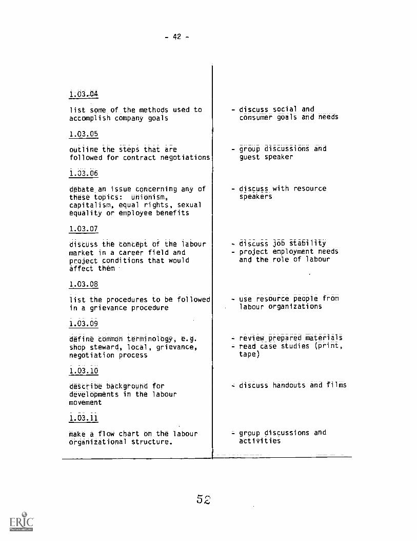
1.03-04
list some of the methods used toaccomplish company goals
1.03.05
outline the steps that arefollowed for contract negotiations
1.03.06
debate_an issue concerning any ofthese topics: unionism,capitalism, equal rights,_sexualequality or employee benefits
1.03.07
discuss_the concept of -the labourmarket in a career field andproject conditiont that Wouldaffect them
1.03.08
list the procedures to be followedin a grievance procedure
1.03.09
define common terminology, e.g.shop steward, local, grievance,negotiation process
1.03.10
describe background fordevelopments in the labourmovement
1.03.11
make a flow chart on the labourorganizational structure.
- discuss social andconsumer goals and needs
- group discussions andguest speaker
- discuss with resourcespeakers
- discuss job stabilityproject employment needsand the role of labour
- use resource people fromlabour organizations
- review prepared materials= read case studies (print,
tape)
- discuss handouts and films
- group discussions and
activities

-43-
MODULE 1.04 WORKING CONDITIONS AND LABOUR LEGISLATION
Goal Statements
The learning experiences in thiS module are deSigned to help eachStudent:
a. become familiar with common requirements and responsibilitiesof an employee;
b. become aware of employee/employer rights under legislation;c. develop an awareness of the legislative process and laws that
protect _employee rights; andd. become familiar with the sources of information relative to
employee rights and responsibilities.
Learning Outcomes Student Activities
The student should be able to:
1.04.01
list examples of proper care ofcompany equipment and materials
1.04..02
list reasons for employeepunctuality in five occupations
1X14_-.03
define 'overtime' in two differentoccupations
1.34_;04
complete various types ofapplications forms, income taxforms; time cards etc.
1.04.05
analyze desirable andnon-desirable considerations thatrelate to a specific geographicallocation for employment
- differentiate betweenrouting maintenance andcareless breakage
- discuss differentoccupational requirements
- discuss labour laws- relate concept of overtimeto salary
- practice completion ofbasic forms that employeesuse
- calculate salary by day,week, month and year
- discuss particular jobs inurban, rural and remoteareas

- 44 -
MODULE 1.05 JOB SEARCH SKILLS AND JOB INTERVIEWS
Goal Statements
The learning experiences in this module are detigned to help each
student:
a. become familiar with a disciplined and methodical approach to
the job search processi__b. review examples of_ proven processes in preparing resumes and
qualifications briefs,c. analyze some_non=;traditional job search skills,
di prepare for job interviews,e. practice methods,of conducting job interviews, and
f. review and_tlarify various methods of arranging and
participation in an interview for employment.
Learning Outcomes Student Activitiet
The student should be able to:
identify the 'hidden' job market
1;05;132
complete two resume outlinet forsimulated situations
draft a covering letter for resume
1 -r05_. 04
examine procedures used to screenapplicants for employment
1;05;05
follow detailed instructions tocomplete an application form
- review methods used bypeople to find jobs
- use various formats,chronological; functional,qualifications brief
- organize information in anapproved format and style
- write letters and comparewith others in class
- discuss various companypersonnel procedures
use and complete sample
application forms

45 -
-L05.06
outline basic steps to_follow forinitial contact with an employer
1.05.07
apply successful job searchtechniques
1.05A1.8
list employment opportunities fora metal trades occupation from asearch of:
- newspaper classifiedsections
- personal contacts- informational interviews
(friends)
- Canada Employment andImmig-ation Commission
1-0S_;09
practice interviewing ski.ilS
1.05.10
prepare a job prospect card
- prepare a letter that__requests an applicationforM
- ditcutS pros and cons ofcontracts by phone, letteror interview
- use resource personnelfrom Canada Employment andImmigration Commission(CEIC)
- list agencies andcrganizations that may becontacted for jobs
- discuss terms andoccupational titles forvarious occupations
- interpret information fromprinted employment wantads
- tape a simulated interviewsituation with otherstudents
- .demonstrate appropriatemanners and etiquette
- writing letters of thankswhere appropriate
- review examples andcomplete a sample

-46-
MODULE 1.06 FIELD TRIPS AND RESOURCE SPEAKERS
_Goal Statements
The learning experiences in this module are &Signed to:
a. provide the opportunity for occupational obterVation byutilizing the resources of the community, and
. involve the community in the educational career development ofstudents.
Learning Outcomes Student Activities
The student should be able to:
1.06.01
write_a synopsis of a film orarticle on a career field of thestudent's choice
1.06.02
contact and arrange for a guestspeaker to visit the class for adiscussion
1.06.03
interview three employers_to__record opinions and_reouirementsthat are deemed to be important toeffective employment
1.06.04
prepare an outline of specificitems on working conditions thatshould be observed during a plantvisit
- view films or articles anddiscuss in class
- discuss procedures and act
as host/hostess
- conduct interviews andmake oral report to clast
- complete writtenevaluation outline

-47=
MODULE 1.07 EDUCATIONAL REQUIREMENTS FOR CAREER PLANNING
Goal Statements
The learning experiences in this module are detigned to
a. enable the student to enter the world of work with an increasedmeasure of competence;
b. help each student increase their awareness of a wide variety ofcareer and educational options; and
c. provide the student with an Underttanding of opportunities forcontinuing education - university, college or Provincialinstitute programs.
Learning Outcomes Student Activities
The student should be able to:
'ALA'
identify the most powerfulreinforcers to their proposedcareer choices
1;07_.02_
list the names and locations ofpostsecondary institutionsoffering courses in three careerfields
1.07.03
demonstrate an ability to definecareer ladders and hOW to reachmore advanced positions
- class discussions
- review entry requirements,program offerings, lengthof terms for specificcourses
- select one career fieldand prepare an educationalplan for report to class
- review a line diagram of acompany organizationpattern
- work from prepared samplesto design a career ladderin a particular field ofinterest
- interview people atdifferent levels in acareer area and assessopinions regarding jobsatisfaction
5 ;1

=48-
UNIT 2.0 SHOP PRACTICES, HUMAN RELATIONS AND SAFETY PROCEDURES
General Aim
The_student should develop and apply positive attitudes toward theapplication of standard -shop practices, interpersonal relations andobservance of safety rulet and regulations.
MODULE 2.01 SHOP RULES AND PRACTICES
Goal _Statements
The learning experiences in this module are detigned to:
a, help enable the student to acquire sufficient skills toidentify; select, maintain and to safely operate shop
equipment;b. increase student awareness of the construction and operating
principles of various items of shop equipment;c. help each student acquire a sensitivity for determining stress
and strain in certain lifting operations; andd. safe use of compressed air. and gas.
Learning Outcomes Student Activitiet
The student should be able to:
2.01.01
identify safety and health hazards
2.01.02
demonstrate good housekeepinghabitt
2.01.03
Maintain a clean and safe wcrkarea
5c;
- locate safety and healthequipment and dittuttreasons for safety andhealth protection
- list areas that requirehousekeeping and variousmethods used
- review both safe and
unsafe work areas

-49-
2;01_;04
use safety_ glasses, Shields,guards, and other protective_clothing according to prescribedstandards
2A1.05
identify and use proper cleaningagents
2.01.06
safely handle and store cleaningagents
2.01.07
describe the deSigh, safeoperating procedures, andMaintenance for general shopequipment
2.01.08
explain first aid for commoninjUries;_lay out procedure ofresponse in_any injury for yourWork situation
2.01.09
describe the need for the usesafety tags
2.01.10
identify and explain the procedureto f011Ow when finding a safetytag on a piece of equipment
2.01.11
State the basic steps to follow infiling a claim with Workers'Compensation Board
- discuss properapplications of protectiveequipment
- study and discuss _thecharacteristicSOfdifferent cleaning_agentSand their applications
- examine safety storageprovided and confiderapplicable regulations
- proper cleaning andmaintenance of equipment
- discuss basic procedure5for reporting anddisposition of injuries
- discuss the need for theuse of safety tags
- discuss the procedure tofollow when finding asafety tag on a piece ofequipment
- discuss the importance ofW.C.B. and their role in
worker safety
J

- 50 -
2.01.12
litt examples Of legal_ protectionfor employees_within Workers'Compensation Board
= discuss legal role ofW.C.B.
= consider limitations offirst aid and importanceofadequate trainingbefore_ treating injuredpersons

-51 -
MODULE 2.02 HUMAN RELATIONS AND PERSONAL ATTRIBUTES
Goal Statements
The learning experiences in thit module are designed to help eachstudent:
a. develop an awareness of their own potential, a sense of pridein accomplishment and confidence in their own ability;
b. develop an awareness of appropriate standards of humanrelations for various occupations;
c; become familiar with techniques for improved interpersonalrelations;
d; develop positive attitudes in relations With teachers andstudents;
e; appreciate the continuing importance of good human relations;f; make an inventory of interests and capacities;g; develop a sense of personal identity and worth;h; considdr the theories of perceiving people as individuals
rather than identification by traditional sex roles in society;i; prepare information regarding interests, temperaments and
aptitudes required for various jobs;j; recognize the importance of appearance and personal ethics to
employment success; andk; become aware of their own individual values and reactions
toward people, situations and themselves.
Learning Outcomes Student Activities
The student should be able to:
2.02.01
exhibit positive behaviour towardsother students
2.02.02
display_acceptable manners in allactivities
- role playing- display approved techni-ques for interpersonalrelationships
- discuss need forappropriate manners

-52-
2.02;03
demonstrate individual differencesin perception
2.02.04
complete a_self=appraisal outlineon personal traits and attitudes
2.02.05
assess strengths, capabilities andweaknesses of people
&02A6
use particular skills necessary togather, process and act_upon_ _
information about self in relationto their environment
2;02.-07
recognize the importance ofstandards in appearance, dress andgrooming, manners; and correct useof the English language
202_;08
list factors that influencediscrimination, i.e. race,religion and sex
62
- use examples of good andpoor relations betweenemployers and employees;teachers and students
- discuss importance ofpersonality; attitudes andhealth to occupations
- assess personal traits andtalents
consider and discussproblems in relation toemployment roles
- discuss the need toconform in specificsituationsreview the importance ofhealth for employment
- list positive and negativepersonal attributes
- discussion of self=development
- observe films- review safe workingconditionS concerningdreSS
- discuss equality ofindividuals
- react_tb examples ofprejudice
4iscuss ways to overcomediscrimination

- 53-
2.02.09
identify five important reasonsfor appropriate dress for anoccupation
2.02.10
provide an example of a conflictsituation created by employee/employer attitudes toward dress
- group discussions
- group discussions

- 54 -
MODULE 2.03 GENERAL SHOP ADMINISTRATION
Goa_l_Statements_
The learning experiences in this module are designed to:
a. provide each student with a working knowledge of fundamental
principles of shop systems; andb. help each student recognize the need for efficiency in shop
administration procedures.
Learning Outcomes Student ActivitieS
The student should be able to:
2.03.01
Outline tool check out system in - become familiar with area
use for tool storage and checkout system
2,03.02
recognize areas where specific - sketch a simplified shop
types of work may take place layout
2.03.03
direct responsibilities in asupervisory capacity ourinup
2.03.04
list reSpOnSibtio required tomaintain aSSignA area

- 55-
MODULE 2.04 EMERGENCY PROCEDURES (FIRE AND MEDICAL ROUTINES)
Goal Statements
The learning experiences in thit module are designed to:
a. introduce the student to approved processes for dealing withemergencies in shop situations; and
b. deScribe the basic operation of four types of fireextinguishers (A B C D)
L#,Irning Outcomes Student Activities
The student should be able to:
2.04.01
demonstrate proper procedures forassigned emergency situations
2.04.02
distinguish between variousclasses of fires
2.04.03
describe the basic operation offour types of fire extinguishers(A B C D)
2.04.4
use appropriate fire extinguisherson different types of fires
6
- discuss common injures- review available safety
films and procedures
- in group activities, usethe correct fire fightingequipment and describecorrect use of an oil fire(in a controlled environ-ment)
- examine all fireextinguishers
- local fire departmentinvolvement
- discuss school emergencyexit procedures
- practice prescribed exitprocedures
- inspect any given piece offire fighting equipmentand state the type of fireon which it may be used
- review locations of
extinguishers.(refer toSketch of shop layout)

- 56-
2.04.05
identify basic_first aid pro-cedures and telephone numbers foremergency assistance
- locate the reqUited_firttaid equipment and diScuSSuse

- 57 -
UNIT 3.0 TECHNICAL - READING, WRITING AND REPORTING
Genera:LAU:I
The student should further develop skill_ for reading, writingand reporting information.
MODULE 3.01 TECHNICAL REPORTS AND WORK SHEETS
Goal- Statements
The learning experiences in this module are designed to:
a. help each student read and interpret technical information,b. increase ttUdent ability to use English in communication,c. encourage neatness -and legibility in all written work, andd. to develop the abilities to record and maintain accurate work
done.
Learning Outcomes Student Activities
The student should be able to:
3.01.01
interpret technical text books andOther reference sources
3.01.02
complete a neat and legible reporton an assigned reporting task
3.01.03
maintain a neat and legiblenotebook on activities
3.01.04
use correct English in verbal andwritten communications
- review various manuals
- at task completion,_ashort concise report is tobe forwarded to theinstructor for evaluation,
- practice completion of
daily work sheets

- 58-
3.-0105
record information in a neat andlegible format
3.01.06
describe in appropriate terms,work performed during a day
3.01.07
complete a basic 'time card' orrecord a work form
- compare samples ofworksheets
- compare various formatsand assess need foraccuracy and neatness

-59-
UNIT 4.0 FASTENERS
General -Aim
The student should develop an understanding of fastening devicesand their selection; installation and maintenance;
MODULE 4.01 TYPES OF FASTENERS
Goal-- Stateme-nts
The learnings experiences in this module are designed to:
a; help each student identify_and select common fasteners,b. inc7ease ability to classify into categories various typOS of
fasteners,C. make students aware of the types and uses of adhesives, andd. make students aware of the consequences of using dissimilar
metals in fasteners.
Learning Outcomes Student Activities
The student should be able to:
4.01.01
identify and classify types ofthreads according to:
a. sizeb. pitchc. thread seriesd. thread classes
= S.I. metric- unified
Imperiale. pipe threads
4.01.02
identify and classifya. types of bolts and machine
screwsb. types of bolt heads
- heX- square= Allen_or socket= Phillipt= Robertson- slotted
study and discuss thereasons for usingdifferent types of threads
- identify threads for avariety of fasteners froma large assortment
- use pitch gauge, steelrule and_calipers tomeasure bolts and nutsizes
- compare common uses ofbolts and screws

- 60-
4.01.03
identify and classify varioustypes of nuts:
- hex- square- slotted hex.- castellated- acorn- pal
interfer-ifncE
- self
4;01_.04_
identify and c1:-iry types of:- flat washers- lock '43s0ers- snap rings
4.01:,06
identify and classify selftapping screws:
- type A sheetmetal screws- drive screws= head shapes
4.01.06
identify and classify varioustypes Of_pins:
= cotter= spring= dowelsaligning
= taper
:= common use of nuts
- Compli common uses of
Wahers
- compare threadconfigurations and commonuses
- compare various types anduses
- compare common uses

=61
UNIT 5.0 TOOLS AND EQUIPMENT
General Aim
The student should develop an understanding of the proper usecare of tools used in the metal trades.
MODULE 5.01 USE AND CARE OF HAND TOOLS
Goal_Statemeht
The learning experiences in this _module are designed to helpstudent identify, select, use and maintain hand tools necessause in the metal tradeS.
Learning Outcomes Student Activities
The student should be able to:
5.01.01
identify and select appropriatehand to0l5 required for use in themetal trade5
5.01.02
demonstrate &knowledge of metricand imperial tool sizes
5.01.03
explain the construction, safehandling and techniques of handtools such as:
= hammers, punches= wrenches, pliers= chisels, files, hacksaws,
drillsvises, clamps
- list usage of hand ti
- use hand tools:- hammers; punches- chisels; pliers,
wrenches- files; hacksaws- screwdrivers- clamp, vises
I

- 62-
MODULE 5.02 MEASURING TOOLS
Goal Statement
The learning experiences in this module_are designed to help eachstudent identify, select and become proficient in handling non-precision and precision instruments,_and interpreting theirreadings (both S.I. metric and Imperial).
Learning Outcomes Student Activities
The student should be able to:
502.01_
state the necessity of measuringinstru-tints such as:
- steel scales
- in jdc calipts- ou calivrs- squares- hermaphrodite calipers- dividers- drill gauge- wire gauge- micrometers (outside,
inside)- vernier calipers- dial indicators- feeler gauges- telescoping gauges- thread gauges
identify the specified steelmeasuring rules ;flexible ornon-flexible) in terms of:
- types- values of graduations- obtainable measuring
accuracy- measuring range- holding techniques formeasuring; checking andlayout operations
- applications- determine and apply thecorrect methods of handling,storing and maintainingsteel measuring rules
- discuss why exactmeasurements are required
- use S.I. metric andImperial
- apply proper handling andmanipulation techniques
- discuss and use measuringinstruments on samplepieces
- use S.I. metric andImperial

- 63 -
5.02.03
identify precision steel squares- types- sizes- holding techniques forChecking and layoutoperations
- applications
5.02.04
identify the micrometer (outside,inside; depth) measuring tools
- types- components and working
principles- attaching and securinnextension rods
- holding techniques formeasuring operations
- setting, locking andmeasuring micrometers atdetermined values
- handling; storing andmaintaining micrometers
5.i02.05
identify vernier caliperstypescomponents and workingprinciples
- holding techniques formeasuring operationssetting and measuringcalipers at determinedvalues
- handling; storing andmaintaining calipers
5A2_;06
identify dial indicators- tyv5
comp:,lents and workingprinciplesobtainable measuringaccuracy
- handling, storing andmaintaining dial indicators
- discuss and use instru=ments on sample pieces
- discuss and in smallgroups use micrometers onsample pieces
- discuss and in smallgroups use verniercalipers on sample pieces.
- discuss the use if dialindicatorS

- 64-
5.02.07
identify feeler gauges- types_- overall checking rangeusing individual andcombination blades todetermine the correctmeasurement.
- hOlding techniques forchecking operations
- handling; storing andmaintaining thickness gaugesets
5.02.08
identify telescoping gauges- overall checking range- applications- holding techniques forchecking operation
- setting; locking and_measuring the overall valVewith the outside micrometer
- handling; storing andm7,intaining telescopinggauges
identify check gauges- drill gauges- wire gauges- pitch gauges - S.I. metric
- Imperial5A020
identify calipers- outside calipers- inside calipers- hermaphrodite calipers
5;02_;11
identify dividers
5y -O2.12
select proper measuring devicesfor specific jobs
- discuss and in smallgroups use feeler gaugeson sample pieces
- discuss the use of tele=scoping gauges on samplepieces
- discuss and use check_gauges where applicable
- discuss and use aliperSwhere applicable
- discuss and use dividers
- study and discuss thereasons and advantages ofeach instrument
= study and discuss thedifferent measuring
systems

-65-
MODULE 5.03 LAYOUT TOOLS
Goal Statements
The learning experiences in this module are designed to:
a; help each student identify, select and become proficient in theuse of layout tools, and
b. help each student use layout tools to produce accurate layoutsto specification.
Learning Outcomes Student Activitiet
The student should be able to:
-5;03;01
identify and list various layouttools:
- scribers (hook, pocket,straight)
- steel rules (metric andimperial
- precision square- combination set- plain steel protractor- hook rule- dividers- angle-plates- hermaphodite calipers- surface-gauge- trammels- centre punch- prick punch- surface plate- toolmakers clamp- vee blocks- scratch awl
- list basic layout tools

-66=
5.03.02
scribe a line parallel to a datumedge using various tools andmethods
- steel rule and scriber- combination set square and
scriber- hermaphrodite caliperssurface plate, angle plateand surface gaugetool makers clamp andsurface gauge
5.0303
scribe a line at 90° to a datumedge using various methods andtools
- combination square- precision square- angle plate, precision
square and surface gauge
503.-04
scribe circles, arcs and tangentlines using various tools andmethods
= dividers or compass- trammels- dividers and steel rule
5.03.05
scribe angles to specificationusing various -tools and methods
- protractorprotractor head (combinationset square)
= vee block and surface gauge= bevel vernier protractor
- layout a project orprojects to include layoutactivities outlined inModules 3.03.02 to 3.03.10to specifications

67 -
5A3_;_f16
layout equal distances withvarious tools and methods tospecification
- dividers, layout equaldistances around acircumference
- dividers, trammels, layoutequal distances along ascribed linelayout parallel iinet withdividerS
- layout perpendicular linesWith dividers_and trammels
= bitett an angle withdividert
5,03.07
find the centre of circles usingvarious tools and methods
- hermaphrodite calipers- dividers- centre,head (combination set
square)- vee blocks and surface gauge
5.03.08
prick punch accurately around afinished layout
5A_3J19
prepare a layout for drilling byprick punching, then centrepunching
5;03;10
layout a double circle with centrelines to facilitate accuratedrilling

p
MODULE 5.04 USE AND CARE OF PORTABLE POWER TOM' AND ACCESSORIES
Goal Statement
The learning experiences in this module are designed to help eachstudent select, use and maintain portable power tools andaccessories iir use in the metal tradet.
Learning Outcomet_
Student Activities
The student should be able to:
5.04.01
recognize the purpose, type andapplication of electrical and airpower tools, i.e.:
- portable drill presses- portable hand drills- portable hand grinders and
polishers
5;04;02
demonstrate the safe and correctuse of electrical and airpower tools
SA04_A3
point out and list the care andservice required for el:_ctricaland air power tools
- study and discuss powertools and accessories
- discuss the effeCt offerrous and non - ferrousmetals on grinding wheelt
- after instruction, useappropriate equipment
- review manuals_andassigned materials

- 69 -
UNIT 6.0 MECHANICAL DRAWING CONCEPTS
General Ain
The student should develop skills to read, sketch, draW andinterpret basic methods used for graphic representation.
MODULE 6.01 BASIC CONCEPTS
Goal Statements
The learning experiences in this module are detigned to:
a; help the student recognize the necessary instruments used into prepare accurate drawings,help the student practice gothic lettering and numberingtechniques, and
c; develop skills in sketching.
Learning Outcomes Student Activities
The student should be able to:
15.01.01
identify types of pencils
6.01.02
identify types of instruments andtheir use
- discuss basic types ofpencils
- hard - 9H, 8H 4H- Medium - 3H, 2H, H, F,
HB, B- soft - 2B, 3B, 4B
7B
- discuss types and uses ofinstruments- T square- set square 300-60°,45°
- triangular architectsscale
- triangular engineeringscale
- triangular metricscale
- irregular curves- protractor- erasing shield
- drawing paper; - tape
other

-70=
6-01-03
identify the reasons for- accuracy- neatness
6A1A4
- discuss
perform gothic lettering and - complete gothic letteringnumbering and numbering sheets
identify the need for spacing and - discuss and practiceuse of guide lines on drawings
&01-05_
sketch= horizontal lines- vertical lines= circles= angles
= discuss and completedrawing sheets

- 71 -
MODULE 6.02 MEASUREMENT
Goat Statements_
The learning experiences in this module are designed to:
a; improve measuring skills with the use of triangular scales, andb. help each student recognize and interpret scale drawings.
simple components.
Learning Outcomes Student Activities
The student should be able to:
6.02.01
identify and use the followingtriangular_ scales
- architect's scale- mechanical_ engineers' scale- metric scale
6.02.02
explain the use of scaledengineering or blueprint drawings
- discuss and use each online measurement exercises
.iscuss

- 72-
MODULE 6.03 PICTORIAL DRAWINGS
Gaal_Statements
The learning experiences in this module are designed to:
a. help each student to recognize arA develbp the basic principlesof pictorial drawings, and
b. develop in each student the ability to freehand sketch and alsoaccurately develop instrument drawings of machine parts.
Learning Outcomes Student Activitiet
The student shoul:, be able to:
6;03.01
identify pictorial drawings
6.03.02
do isometric drawings= freehand sketching- with drafting instruments
6.03.03
do perspective drawings= one=point perspectivetwo=point perspective
6.03.04
identify and skPtch obliquedrawings
cavalier= cabinet
- discuss
discuss.and completeisometric drawings
- sketch perspectivedrawings
- sketch oblique drawings

- 73 -
MODULE 6.04 ORTHOGRAPHIC DRAWINGS
Goal Statements
The learning experiences in this module are designed to:
a. help each student recognize and develop concepts ororthographic drawings,
b; develop in each student the ability to freehand sketch anddevelop instrument drawings machine parts, and
c. increase student ability to read orthographic drawing andrelate them to actual components.
Learning Outcomes
The student shoo d be able
identify orthographic drawings discuss
_6_;_04.G2
Student Activitiet
complete a one-view drawing- freehand sketchinginstrument drawing
6.04.03
complete a two-view drawing= freehand sketching= instrument drawing
6.04.04
complet a three-view orthographicdrawin.i n third angle projection
freehand sketching- instrument drawing
- discuss and completeo7e-view drawingt
- discuss and completetwo-view drawings
- discuss and completethree-view orthographicdrawings

- 74 -
6.04,05
relate lines and sirfaces betweenpictorial and orthographicdrawings
discuss and completeunfinished vies
- reference text (blueprintreading fir industry)

- 75 -
MODULE 6.05 CONVENTIONAL LINES AND SYMBOLS
Goal Statpment
The learning experiences in this module are designed to help eachstudent read and interpret the meaning of conventional lines andsymbols used in graphic representation;
Learning Outcomes Student Activities
The student should be able to:
6.05.01
identify basic lines used ingraphic representation
= be -der or visible linessection
= hidden= Centre!- extension- di,nension_= Cutting plane= short break- long break- leaders- phantom
other
6.05.02
identify basic syMbolS used ingraphic representation
- arrowheads- diameter symbol (D) (0)
- radius symbol (R)_- countersink (C'SK)- cold roll steel (C.R.S.)- hot roll steel (H.R.S.)- hexagon (HEX)- others
= discuss and list basiclines
- discuss 3nd list basicSymbol-.

-76-
_6_;11503
identify surface finish ratings10C. very rough (torch
cut)- 500 rough machining
(heavy cut on millmachine)
- 250 'coarse (coarsemachining operationwith sharp tool)
= 125 medium (finemachining operationwith sharp tool)
= 63 good mdchine_finish(extra fi-ne feeds)
32 high grade machinefinish (extremelyfine feed on latheor mill)
= 16 nigh quality machinefinish (Su7facegrinding)
= 8 very fire machinefinish ine honingur lapping)
- 2=4 extremely smooth(extra -fine honingor lapping)
- recoanize and list symbols

- 77 -
MODULE 66 CONVENTIONAL CONCEPTS
Goal Statements
The learning experiences in this module are designed to:
a; help each student acquirecompetency in conventional conceptsof dimensioning and use of symbols,
b. help students understand auxiliary viewsi_andc. help each student understand the use of different types of
sectional views.
Learning Outcomes StuU nt Activities
The student should be able to
6.06.01
identify material symbols= britkconcrete
- rubble and Stone- steel
- wood- perforated metal- marb16- coarse wire meshfine wire mesh
- cast ironbronze; brass
- aluminium- white metal, babbit
6.06.02
identify schematic threadingsymbols
- external- internal
- discuss and list sectionlinings
- discuss

=78=
6.06.03
select proper placement ofdimension and extension lines on adrawing
6.06.04
dimension= figures- angles= arcs= fillets and rounds= hOleS- threads- tapers- chaMfers
keyways= knurlS
6.06.05
*ify special Methods in.sioning- baseline- point to point- datUm- tolerancing- fits- other
6.06.06
identify the purpose of anauxiliary view
8;_08;__07_
identify the purpose of sectionalviews
- discuss rules fordimensioning drawings
- identify the- unidirectional- aligned system
- discuss and completedrawings
- recognize and list specialdimensioning methods
- discuss and complete a7!-awing using an auxiliary",e0

- 79-
6.06.08
identify the types of sectionalViews
full section- half section- broke-out section- revolved section- removed section- other
identify welding symbols
6.06.10
identify architectural symbols andscheduleS
- mechanical- electrical= structural
- discuss and completesectional views of parts
= recognize and list Weldingsymbols
recognize and list symboland Scheduleg

- 80-
UNIT 7.0 FT ',.ND SILVER SOLDEPING
General Aim
The student should .gain experience using_approved practices for thesafe management and operation of SOft_and silver_soldering!quipment and gain proficiency in various soldering operations.
MODULE 7.01 SOFT SOLDER
_Statements
The learning experiences in this module are designed to:
a; develop skills in the proper preparation of soldering coppersfor soft soldering;
b; help each student select proper fluxes for various solderingoperations;
c; make the student aware of the composition of tin-lead solder;d; help the student understand the uses of soldered_ joints;e; make the student aware of the potential danger of flu>0.
Learning Outcomes Student Activities
The student should be able to:
7_;_01_;01
forge a soldering copper
7.01.02
tin a copper
7.01.03
select fluxes for specificoperations
- discuss various solderingcopper shapes such aspointed and bottom copper
- heating and mechanicalcleaning of coppers
- chemically clean and tin
copper
- discuss purposes of a fluxcorrosive and noncorrosivefluxes; safe handling andstorage
- use fluxes for plated andbright steels andnonferrous metals

= 81
7.01.04
ditCutt_the composition and formson tin-lead solder
7.01.05
explain the various uses of softsolder joints
- discuss solders forvarious applicatiOns -
50 -50, 60=40, 95-5, bodyleads etc.
- study various forms:- wire _
- cored wire= bar
Sheet
- discuss_soldering forwater-tight joints insheet metal and plumbinairtight joints forblowpiping, sweatSOldering for partsassembly.

- 82 -
MODULE 7.02 SOFT SOLDER APPLICATION
Goal Statements
The learning experiences in this module are designed to:
a. student aware of the safe procedureS in soldering,
b. he'. student become proficient in applying_Soft solder, and
c. he student become proficient in suface cleanup after
so 3.
learning Outcomes Student Activities
The student Should be able to:
7.02.01
explain the safe procedures forsoldering
7.02.02
properly apply soft solder withsoldering coppers and open flametorch
7.02.03
clean metal SuffateS aftersoldering operations
- study and discuss dangersinherent in various fluxes
- lighting firepots,furnaces and torcheSsafely
- handling hbt work safety
- prepare and solder variousjoints such as:
- lap- rivetteJ- seamed- pre-tinned- plumbing
- remove corrosive fluxesand restore surface finishof various metals such as:
- bright steel- nonferrous- stainless steel

MODULE 7.03 SILVER SOLDER
Goal Statements
The learning experiences in this Module are designed to:
a; assist the student to understOod the need for silver soldering.b. help the student to safely apply silver solder to metal joints,
andc. help the student become proficient in surface cleaning up after
silver soldering.
Learning Outcomes Student Activities
The student should be able to:
7.03.01
select and prepare joints forsilver soldering
7.03.02
apply silver solder using openflame torch
7.03.03
Clean metal surfaces after 'Inversoldering
- discuss applications ofsilver soldering
- discuss and fabricatescarf and butt joints andsweat solder joints
- apply silver solder inproper amounts to variousjoints
- remove correive fluXeSand restore surfacefinishes on ferrous andnonferrous metOlS

- 84 -
UNIT 8.0 GAS WELDING OPERATIONS
General Aim
The student should _gain experience using approved practices for thesafe management aid operation of gas welding equipment.
MODULE 8.01 WELDING SAFETY PRACTICES
Goal Statement R
The learning experie: es in tnis module are designed to:
a. help each stud9.: appreciate the importance of applying Safepractices in t;: use of gas welding equipment,
b. introduce the stAent to methods of checking gas weldingequipment beforr.: operating on welding or heating catkt, and
c. increase student awareness of the characteristics of gases usedfor heating zi:u welding operations.
Learning Outcomes Student Activitiet
The student should be able
8.01.01
identify the safety regulationsfor gas welding, cutting and
to ensure a safe workingenvironment
- read and discuss Workers'Compensation BoardSections 14, 17, 18.

- 85 -
MODULE 8.02 STORAGE AND HANDLING OF OXYGEN AND FUEL GAS CYLINDERS
Goat Statement
The lelrning experiences in this module are designed to ensure thateach st!ident can safely handle and store oxygen and fuel gascylinders;
Learning Outcomes Student Activities
The student _0'lould be able to:
8.02.01
demonstrate the correct storageand handling practices ofoxygen and fuel gas cylinders
- identify coi-7ect storagepractices for empty Oxygencylinders
- identify correct storag'7'actices for_emptykcetytene cylinders __
- identify correct handlingpractices for full Oxygencylinders
- ident i -_orrect_handlingpractice:; fOr_fUllAcetylene cylinders
- identify correct procedurein removal of defeCtiVeAcetylene cyllAer frOMService
- ioentify correct mode oftransporting cylinders inShOp
- transport to and_storeempty cylinders in Stora(jearea

-86-
MODULE 8.03 HANDLING AND OPERATING OXY-ACETYLENE EQUIPMENT
Goal Statement
The learning experiences in this module arc designed to enable eachStudent to correctly h.:ndle and operate oxy-acetylene equipment.
Learning Ou'ccome.; Student Activities
The student should be able to:
8.03.01
deSCribe correct handling andOperating practiCe of oxy.=
acetylene equipment
crack cylinder and purgevalve with appropriatewrench
- identify appropriateregulator to be usedidentify types of threadson acetylene equipmentdescribe why an Oxygenregulator is set facingaway from a acetyleneregulatordescribe how oxy-acetylenefuel gas hose is storeddescribe correct method inpurging oxy-acetylene
- describe the effect of oiland grease in contact withoxygendescribe correct equipmenthandling practices
- describe correct equipmentoperating practices

-87-
MODULE 8.04 ASSEMBLY OF OXY-ACETYLENE EQUIPMENT
as Statremmt
The learning experiences in this module are designed to enable thestudent to correctly and safely assemble oxy-acetylene equipment.
Learning Outcomes Student Activities
The student should be able to:
8;04;.01
correctly assemble a portable oxyacetylene unit
= select place and securecylinders in cart
- remove cap and crackcylinder valves
- attach regulators andhoses with proper wrench
- release regulatoradjusting screw, opencylinder valve and setpressure to blow out hose
- open needle valves, attachtorch assemble and blowout torch assembly
= attach welding or cuttingapparatus to torch bodysecurely.

-88-
MODULE 8.05 TESTING FOR LEAKS
Goal Statement
The learning experiences in this module are designed to enable thestudent to safely test oxy-acetylene equipment for leaks.
Learning Outcomet Student Activities
The student should be able to:
8.05.01
demonstrate correct procedures andmethods in testing for leaks
- describe methods_ employedin detecting leaks inoxygen and fuel gassystems_
*- pressurize oxy-acetyleneequipment and adjustregulator to workingpressure__
*- close cylinder valve andobser've high pressuregauge on regulator
*- determine pressure drop,if any
*- apply nondetergent soapsuds with brush to jointsand connections
*- depressurize oxy-acetyleneequipment and makenecessary repair
- repeat * and determineoutcome of repair
*star denotes repeat ofoperation

-89-
MODULE 8.06 CORRECTLY LIGHT AND SHUT DOWN THE OXY-ACETYLENE UNIT
Goal Statement
The learning experiences in this module are designed to enable thestudent to correctly light and safely shut down the oxy-acetyleneunit.
Learning Outcomes Student Activities
The student should be able to:
8.06.01
correctly light an oxy-acetyleneunit
8_06.02
shut down the oxy-acetylene unitsafely
- employ general and per-sonal safety precautions
- identify tip size andselect appropriate oxygenand acetylene pressures
- test connections for leaksusing detergent, soapywateropen acetylene valve ontorch and light withStriker. Adjust acetyleneflow until smokedisappearsopen oxygen needle valveuntil complete combustionof acetylene occursadjust torch to neutralflame setting
= review general safetyprecautions-
= close acetylene needlevalve on torch body
= close oxygen needle valveon torch body
- close acetylene cylindervalve, open acetyleneneedle valve on torch body
- turn out pressureadjusting screw onacetelyene regulator, thenclose needle valve
- close oxygen cylindervalve, open oxygen needlevalve on torch body
- turn out pressureadjusting screw onoxygen regulator then
close needle valve= coil oxy - acetylene hose on
unit.

- 90 -
MODULE 8.07 TORCH LINE EXPLOSIONS
Goal Statement
The _learning _experiences in thiS_module are designed to enable thestudent to identify the causes of torch line explosions.
Learning Outcomes_
Student Activities
The ttudeht should be able
8.07.01
identify the causes of flathback,backfire, burnback
- dettribe tOhditiOnt andcauses for a flathbatk
- describe conditi-oht andcauses for a backfire
- identify equipmentmaintenance procedures toeliminate explosions
- describe gas speed andspeed Of flame propagation
- identify _the purpose of areverse flOW chetk valve(RFCV)
- identify conditionscausing a burnback
Information note
Backfire - the flame backtup into the tipand generallyreestablishesitself with abang or poppingnoise
Burnback - combustion takesplace steadilyin the tip andmixer
Flashback - occurs when onegas backs upinto the otherline forming anexplosive mix-ture. Flashbackalways occurs inthe line carry-inq_the_lowerpressure.

-91 -
MODULE 8.08 FIRE PREVENTION
Goal Statement
The learning experiences in this modUle are detigned to enable theStudent to identify the requisites in fire prevention.
Learning Outcomes Student Activities
The student should be able to:
8_;08_.01
identify the requisites in fireprevention
- define the term fireprevention
- describe the welder'sresponsibilities for fireprevention
- describe the employers'responsibilities for fireprevention
- describe conditionscreating fire hazards andexplosions
- identify remedies toeliminate fire hazards andexplosions
- identify the importance ofa fire watcher

-92=
MODULE 8.09 FIRE EXTINGUISHERS
Goal Statement
The _learning _experiences in this module are designed to enable thestudent to identify the components of a fire, types of fires, andextinguishers.
Learning Outcomes Student Activities
The student should be able
8.09.01
identify pressurized A, and C
type fire extinguishers
= describe the requisitesfor a fire
= describe the types offires
- describe the classes offiresdescribe the types of fireextinguishersdescribe the classes offire_extinguishers
- identify the types of fireextinguishers used toextinguish rubbish andpaper fires_
- identify types of firescombated with CO2 fireextinguishers
- identify the uses of_A,C, fire extinguishers

-93-
MODULE 8.10 VENTILATION
Goal Statement
The learning experience§ in this module are designed to_give asimulated working environment to enable the student to identifyventilation requirements for welding, cutting and general shopwork.
Learning Outcomes Student Activities
The stUdent should be able to:
8.10.01
identify ventilation requirementsfor welding, cutting and generalshop work
- review SeCtion #17,Workers' COMpensationBOard_Regulations forVentilation requirements
= identify conditions thatrequire ventilation
- identify materials thatemit toxic_fumes whenheated, welded or cut withtorch__identify precautionsrequired when working inconfined areas

-94=
MODULE 8.11 WELDING AND CUTTING CONTAINERS
Goal Statement
The learning experiences in this module are designed tei enable thestudent to identify the correct and safe methods for welding andcutting containers.
Learning Outcomes Students Activities
The student should be able to:
8.11.01
identify the extreme hazardsinvolved in welding or cuttingcontainers that are sealed orcontainers that have heldcombustibles
- study_and discuss safemethods of welding orcutting_containers
a. steam cleaningb. purging using inert
gasesc. filling with water

- 95 -
MODULE 8.12 PROTECTIVE EQUIPMENT
Goal Statement
The learning experiences in this module are designed to enable thestudent to select and use protective equipment in welding.
Learning Outcomes Student Activities
The student should be able to:
8;12_;01
identify and select properprotective equipment
- describe the reason forwearing safety glasses
- describe uses and types ofgoggles in welding andcutting
- describe the uses andtypes of welding helmets
- describe the use of tintedor coloured lenses inwelding and cutting andtheir shade description
= identify types of hearingprotection equipment used
- identify the advantage ofusing leather jackets inwelding and 'cutting
- identify the advantages ofusing leggings and apronsin welding and cutting

-96=
UNIT 9.0 OXY-ACETYLENE EQUIPMENT
General Aim
The student should identify, understand, and use oxy-acetylenewelding equipment.
MODULE 9.01 OXY-ACETYLENE WELDING EQUIPMENT PROCESSES ANDAPPLICATIONS
Goal Statement
The learning experiences in this module are designed to provideintroductory experiences that will enable the student to identify,understand, and use basic.oxy-acetylene welding equipment.
Learning Outcomes Student Activities
The student should be able to:
9.01.01
describe the_production and - describe the nature ofproperties of oxygen and acetylene oxygengas - describe the properties o;'
oxygen- describe the production of
oxygen= de-Scribe the nature ofacetylene -
- describe the properties ofacetylene
- describe the production ofacetylene
1j

-97-
MODULE 9.02 CONSTRUCTION OF OXYGEN AND FUEL GAS CYLINDERS
Goal Statement
The learning experiences in this module are designed to provideintrOdUCtOrY experiences that will teach the student to identify,underStand, and use basic oxy-acetylene welding equipment.
Learning Outcomes Student Activities
The student should be able :
9.02.01
describe the construction ofoxygen and Fuel gas cylinders
- state agencies that governstandards in cylinderconstruction
- describe the constructionof an oxygen cylinder
- describe the function ofthe oxygen cylinder valve
= describe the function ofthe oxygen cylinder valvecover
= describe the constructionof an acetylene cylinder
- describe the constructionof an acetylene cylindervalvedescribe the constructionof a fusible plug and itslocation
- describe the constructionof a mapii--gas cylinder andvalve

MODULE 9.03 CONSTRUCTION OF PRESSURE REGULATORS
Goal_Statement
The learning experiences in this module_are designed to provide
introductory experiences that will enable the student to identify,
understand, and use basic oxy-acetylene welding equipment.
Learning Outcomes Student Activities
The student should be able to:
9.03.01
identify_the construction andapplication Of regulators on oxyacetylene equipment
- state purpose of a _
pressure-reducing devicein oxy-acetylene equip-ment
- describe the constructionof the single and doublestage regulator
- identify the limitationsof a single stageregulatoridentify the operatingcharacteristics of atwo-stage acetyleneregulator
= identify correctmaintenance procedures forregulators

-99-
MODULE 9.04 OXYGEN AND FUEL GAS HOSE
Goal Statement
The learning experiences in this module_are designed to provideintroductory experiences that will teach the Student to identify,understand; and use basic oxy-acetylene welding equipment.
Learning Outcomes Student Activities
The student should be able to:
9_;04_;_01
identify the correct maintenancepractices for oxygen and fuel gashoses
- describe the constructionof twin design oxygen andfuel gas hose
- identify the colouringscheme employed toseparate oxygen and fuelgases
- identify the thread designemployed in the fuel gashose connector fittings-
- identify correct practicesin splicing of oxygen ;andfuel gas hose
- identify correct practicesin coiling and storingoxygen and fuel gas hoses

- 100-
MODULE 9.05 OXY-ACETYLENE TORCHES
Goal Statement
The learning experiences in this module are designed to provideintroductory periences that will enable the student to identify,UnderStand, and use basic oxy-acetylene welding equipment.
Learning Outcomes Student Activities
The student should be able
9.05.01
identify and describe two types ofoxy- acetylene torcheS
= describe the function of abalanced_ pressure typemixing chamberdescribe the function ofan injector type mixingchamber
= identify the limitationsof a one-piece torchidentify_the advantagesand disadvantages of atwo-piece torch
= identify correct methodsin installing heating,cutting and welding tips
= identify correctMaintenance practices forone and two -piece torches
Liu

- 101 -
MODULE 9.06 MANIFOLD SYSTEMS
Goal Statement
The learning experiences in this_moduTe_are designed to provideintroductory experiences that will enable the student to identify,understand, and use basic oxy-acetylene welding equipment.
Learning Outcomet Student Activities
The student should be able to:
9.06.01
identify the application of amanifold system
- identify types of manifoldsystems
- identify regulations andstandards governingconstruction and operationof manifold systems
- identify and define theterm 'pickled pipe'
- explain the requirementsfor a hydraulic backpressure valveidentify the purpose ofpigtails and check valves
.= identify the purpose of amaster_ regulator
- identify -the advantagesand disadvantages of amanifold system

102-
MODULE 9.07 SELECTION OF FLAMES
Goal Statement
The learning experiences in this module are designed to provide_
intrOdUctOry experiences that will enable the student to identify,
underStand, and use basic oxy-acetylene welding equipment.
Learning Outcomes Student Activities
The student should be able to:
identify the use of neutral,_oxidizing; and carburizing flamesin oxy-acetylene welding andcutting
= identify the types offlames
= identify the temperatureranges for neutral;oxidizing and carburizingflames
= identify and define the 3X
flame systemdetermine the use of a 3Xflame
.- identify the type of flameemployed in oxy-acetylenecutting and welding ofplain carbon steel

- 103 -
MODULE 9.08 TIP SELECTION AND MAINTENANCE
Goal Statement-
The learning experiences in this module_are designed to provideintroductory experiences that will enable the student to identify,understand, and use basic oxy-acetylene welding equipment.
Learning Outcomes Student Activities
The student should be able to:
9.08.01
identify and select the correctwelding or cutting tip
9.08.02
perform tip cleaning procedure
- identify types of cuttingtips
- identify purpose of
numbering systems used- install selected tipemploying accepted methods
- identify condition ofmodels
- identify maintenanceprocedures employed fortip cleaning

- 104-
UNIT 10.0 OXY-ACETYLENE WELDING, BRAZING AND CUTTING (O.A.W.)
General Aim
The student should gain experience using approved practices for thesafe management and operation of oxy-acetylene welding, brazing andcutting.
MODULE 10.01 WELDING POSITIONS
Goal Statement
The learning experiences_in this module are designed to provide theStudent with the letter identification for groove (G) and fillet(F).
Learning Outcomet Student Activitiet
The student should be able to
10.01;01
identify the accepted positions ofwelding
- review handout onpositions of welding
- identify the -F- positions- identify the -G- positions

- 105 -
MODULE 10.02 SELECTION OF FILLER METALS
Goal Statement
The learning experiences in this module are designed to enable thestudent to select filler metals.
Learning Outcomes Students Activities
The student should be able to:
10.02.01
identify and select proper fillerrod
10._02,02
select an R.G. 60 rod
= review gas welding fillermetalsidentify type of steel tobe joined.
- identify types of gaswelding rods
= select one filler rod fromstock and match withproperties of steel
- identify selected fillerrod

- 106-
MODULE 10.03 FOREHAND WELD
Goal Statement
The learning experiences in this module are designed to enable thestudent to become proficient in using the forehand method ofwelding.
Learning Outcomes Student Activities
The student should
1003.01
able to:
forehand weld with theoxy-acetylene welding process(O.A.W.)
Refer to:
Provincial WeldingLevel "C"Forehand WeldModule: P 3Goal 11Performance Objective: #2
urriculum
- employ general andpersonal safetyprecautions
- select piece of M.S.1/8" x 6" x 8 "; removeoxides and place in flatposition
- select tip, install,choose and set correctoxy-acetylene pressuresand light torch
- right handed person, holdtorch with flame pointingto left; lower flame ontoplate
- hold flame 1/6" overplate, preheat and createpuddle
- oscillate torch and movefrom right to left in astraight line holdingtorch at 45°
- review progress and repeatprocedure
116

-107-
MODULE 10.04 BEADING
Goal Statements_
The learning experiences in this module_are designed to enable theStudent to become proficient in bead welding with the O.A.W.process.
'earning Outcomes Student Activities
The student'should be able to:
10.134A1
deposit beads with-the O.A.W.process
Refer to:
Provincial welding CUrriculumLevel AC" _
Gas Welding PracticlModUle: P 3Goal 11Performance Objective #3
- read specification sheetand employ general safetyprecautions
- select base metal andfiller material
- select tools and.equipmentfor job
- determine sequence ofoperation and employpersonal safetyprecautions
*- clean metal surfaces andplace metal in flatposition
*- heat to desiredtemperature
*- apply filler metal withthe dipping method andemploy forehand technique
*- let cool and performspecification check
- repeat process and follow* tasks
*star denotes repeat ofoperation

- 108-
MODULE 10.05 CORNER JOINT
Goal Statement
The learning experiences in_thit module are designed to enable the
student to weld a corner joint with the O.A.W. process.
/
Learning Outcomes Student Activities
The student should be able to:
10.05.01
fusion weld a corner joint, withthe 0.A.W. process
Refer to:
Provincial Welding CurriculumLevel !T"Gas Welding PracticalModule: P 3Goal 11Performance Objective: #4
- read specification sheetand employ general safetyprecautions
- select base metal andfiller material required
- select tools and equipmentfor job
*- determine sequence_andposition of operation
*- clean metal surfaces,assemble and support partsto be joined
*- employ personal safetyprecautions
*- heat to desiredtemperature, tack weld inappropriate places Andplace joint into position
*= apply filler metal intojoint, employ forehandwelding technique
*= let cool and performspecification check
= follow repeat procedureson handout and follow *tasks.

=109=
MODULE 10.06 LAP JOINT
Loal_Statements
The learning experiences in_this odule-are designed to enable thestudent to perform a lap weld with the O.A.W. process.
Learning Outcomes Student Activities
The student should be able to:
10.06.01
fusiOn Wld 6 lap joint with theO.A.W. pru;:ess
Refer to:
Provincial Welding CurriculumLevel "C"Module: P 3Goal 11Performance Objective: #4
- read specification sheetand employ general safetyprecautions
- select base metal andfiller material required
- select tools and equipmentfor job
*- determine sequence andposition of operation
*- clean metal surfaces,assemble and support partsto be joined
- employ personal safetyprecautions
- heat to desiredtemperature, tack weld inappropriate places andplace joint into position
*- apply filler metal into,joint; employ forehandwelding techniques
*- let cool and performspecification checkfollow repeat procedureson handout and follow *tasks.
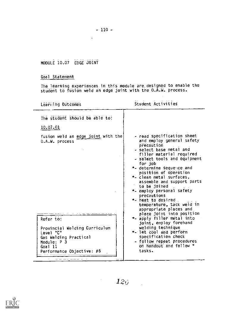
- 110-
MODULE 10.07 EDGE JOINT
Goal Statement
The learning experiences in this module are designed to enable thestudent to fusion weld an edge joint with the O.A.W. process.
LearRing Outcomes Student Activities
The student should be able to:
10.07.01
fusion weld an edge joint with theU.A.W. process
Refer to:
Provincial Welding CurriculumLevel "C"Gas Welding PracticalModule: P 3Goal 11Performance Objective: #6
- read specification Sheetand employ general safetyprecaution
- select base metal andfiller material Tequired
- select toolt and equipmentfor job
*- determine seque'lce_andposition of operation
*- clean metal surfaces,assemble_and support partsto be joined
*- employ personal safetyprecautions_ _
*- heat to desiredtemperature, tack weld inappropriate places andplace joint into position
*- apply filler metal intojoint, employ forehandwelding technique
*- let cool and performspecification check
- follow repeat procedureson handout and follow *tasks.
l2

MODULE 10.08 TEE JOINT
Goal- Statement
The learning experiences in this module are designed to enable thestudent to fusion weld a tee joint with the O.A.W. process.
Learning Outcomes Student Activities
The student should be able to:
10.08.01
fusion weld a tee joint with theO.A.W. process
Refer to:
Provincial Welding CurriculumLevel "C"Gas Welding PracticalModule: P 3Goal 11Performance Objective #5
- read specification sheetand_employ_General SafetyPrecautions
- select base metal andfiller material required
- select tools and equipmentfor job
*= determine sequence_andposition_Of operation
*= clean metal surfaces,assemble and support partsto be joined
*- employ_ personal safetyprecautions_
*- heat to deSited tempera-ture, tack weld inappropriate places andplace joint into potition.
*- apply filler Metal_intojoint, OmplOy_forehandWelding_tethnique
*= let cool and performSpetifitatiOn check
- f011OWHrepeat procedureson handout and follow *taSkt.

- 112 -
MODULE 10.09 BUTT JOINT
Goal Statement
The learning experiences in this module are designed to. enable the
Student to fution weld a butt joint with the 0.A.W. process.
Learning OutcOMes Student Activities
The student should be able to:
10;09.01
fusion weld a _butt joint with the
0.A.W. process
Refer to:
Provincial Welding CurriculumLevel "C"Gas Welding PracticalModule: P 3Goal 11Performance Objective #7
- read specification sheetand employ general safetyprecautions
- select base metal andfiller material required
- select tools and equipmentfor job
*- determine sequence andposition of operation
*- clean metal _surfaces,assemble_and support partsto be joined
*- employ personal safetyprecautions-
*- heat to desired tempera-ture, tack weld inappropriate places and_place joint into position
*- apply filler metal intojoint, employ Forehandwelding_technique
*- let cool and performspecification check
- follow repeat procedureson handout and follow *tasks
1,2z

- 113-
MODULE 10.10 FUSION WELD OF CAST IRON
Goal Statement
The learning experiences in this module are designed to enable thestudent to fusion weld cast iron using the 0.A.W. process.
Learning Outcomes Student Activities
The student should be able to:
fusion weld grey cast iron withthe O.A.W. process.
Refer to:
Provincial Welding Currici,lumLevel "C"Gas Welding PracticalModule: P 3Goal 11Performance Objective #13
read specification sheetand employ general safetyprecautionsbevel joints and assureaccurate fitup of castironclean metal surfaces;assemble and support castiron
- sear metal surfaces andapply appropriate preheat
- preheat cast iron todesired temperature
- heat filler metal andapply fluxing agent
- apply heat to attainmelting temperatures; addfiller metal
- continue fusion weldingthe forehand method andcomplete weld
- cool slowly to roomtemperature and performspecification check.
in
Information_Nota:
Cast iron should not bequenched; But be cooledunder controlled conditions

- 114-
MODULE 10.11 BRAZE WELDING
Goal Statement-
The learning experiences in this module are designed to:
a. define the braze welding process,b. identify filler metals,_C. identify types of fluxes,d. identify flame type in braze welding, ande. identify types of edge preparations.
Learning Outcomes
The Student should be able to:
10.11.01
define the braze welding process
10.11.02
identify filler metals
Student Activities
- read handout- explain what occurs in
liquid-solid phase joining- describe 2 types of
processes- identify the types of heatrequired for braze welding
- identify correct surfacepreparations in brazewelding
- identify the properties offiller metals in brazewelding
- identify the nature of the
braze bond
- read handout= identify type of basemetal to be joinedidentify the mainconstituent metal in acopper base alloy weldingrod
- identify the properties ofzinc in the braze weldingprocess
- identify a low fumingbronze alloy in brazewelding
- identify a common type offiller metal used in braze
welding

- 115-
10.11.03
identify types of fluxes
10.11.04
identify flame type used in brazewelding
LL_11A5
define the types of edgepreparations
- read handout __
- define -the term flUk- identify types of_fluxesand their properties-
- identify two types of fluxemployed in braze welding
- identify the type of fluxon the coated non fumingRCUZN-C filler metal
- read handout- identify the effect of a
reducing flame in brazewelding
- identify the effect of ahighly oxidizing flame
- read handout- describe the nature of the
braze bond- identify the effect of
searing- identify the desired bevelangle in braze welding
- identify the purpose offluted bevels
- identify the effect ofunbroken edges on thebraze bond

- 116 -
MODULE 10.12 BRAZE WELDING
Goal Statement
The learning experiences in this module are designed to provide the
student with the opportUnity_to deposit_beads with RCUZN-C filler
metal on M.S. plate. (Mild Steel. Plate)
Learning Outcomet Student Activities
The student should be able to:
10.12.01
deposit beads with RCUZN-C fillermetal on M.S. plate
Refer to:
Provincial Welding CurriculumLevel "C"Braze Weldi_ng PracticalModule: P 3Goal 12Performance Objectime #1
- read specification sheetand employ general safetyprecautions
- identify filler metal andselect base metalclean metal surface andemploy_ personal safetyprecautions
- choose correct O.A. flameand heat base metal todetited_temperature
- employ_ forehand technique,add filler, observetinning action
- proceed to deposit fillermetal

- 117-
MODULE 10.13 BRAZE WELDING
Goal Statement
The learning experiences in this module are designed to_provide thestudent with the opportunity to perform braze welds to lap joints.
Learning Outcomes Student Activities
The student should be able to:
10.13.01
perform braze welds on lap joints
Refer to:
Provincial Welding CurriculumLevel "C"Braze Welding PracticalModule: P 3Goal 12Performance Objective #2
read specification theetand employ general safetyprecautionsselect base metal andfiller material _requiredselect_tools and equipmentfor jobdetermine sequence_andposition_of operationcleanmetal _turfacet,assemble and support partsto be joined.employ personal safetyprecautions_heat to desiredtemperature, tack weld inappropriate places andplace joint into positionapply filler metal_intojoint, employ_ Forehandwelding_techniquelet cool and poirot-71i
specificatiOn thetk,follow repeat*_procedureton handout and follow *tasks

- 118-
MODULE 10.14 BRAZE WELDING
Goal Statement
The _learning experiences in this module are designed to provide theStudent with the opportunity to braze weld tee joints.
Learning Outcomes Student A:tivities
The student should be able to:
10.14.01
Braze weld tee joints
Refer to
Provincial Welding CurriculumLevel "C"Braze Welding PracticalModule: PGoal 12Performance Objective #3
- read specification sheetand employ general safetyprecautions
- select base metal andfiller materials required
- select tools and equipmentfor job
*.= determine sequence andposition of operation
*--= clean metal surfaces,assemble and support partsto be joinedemploy personal safetyprecautions
*- heat to desiredtemperature, tack weld inappropriate places andplace joint into position
*- apply filler metal intojoint, employ forehandwelding techniquelet cool and performspecification check
- follow repeat procedureson handout and follow *tasks
1:2,3

- 119-
MODULE 10.15 BRAZE WELDING
Goa -1- Statement
The learning experiences in this module are designed to provide thestudent with the opportunity to braze weld M.S. plate.
Learning Outcomes Student Activities
The student should be able to
10.15.01
braze weld M.S. plate
Refer to:
Provincial Welding CurriculumLevel "C"Braze Welding PracticalModule: P 3Goal 12Performance Objective #4
- read specification sheet,employ general safetyprecautions
- bevel joint and assureproper fitup of plate
- clean metal surfaces,assemble,_ space andsupport plate
- employ personal safetyprecautions
= heat to desiredtemperature
= tin_joint and pruceed tofill groove_
= let cool and apply finalcleaning
- perform specificationcheck

- 120-
MODULE 10.16 BRAZE WELDING
Goal Statement
The learning experiences in this module are designed to provide the
student with the opportunity to braze weld cast iron.
earning Outcomes Student Activities
The student should be able to:
10_;16.01
braze weld grey cast iron
Refer to:
Provincial.Welding CurriculumLevel "C"Braze Welding PracticalModule: P 3Goal 12Performance Objective #5
- read specification sheet.and employ_general safetyprecautions
- prepare joint and assureproper fitup
- clean metal surfaces,assemble, space andsupport cast iron
- employ personal safetyprecautions
- sear metal or jointsurtace and preheat todesired temperature
= assure good tinning andproceed to fill groove
= cool slowly and applyfinal cleaning
- perform specificationcheck
- do not quench
13i
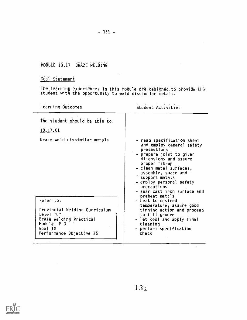
- 121 -
MODULE 10.17 BRAZE WELDING
Goal Statement
The learning experiences in this module are designed_to provide thestudent with the opportunity to weld dissimilar metals.
Learning Outcomes =
Student Activities
The student should be able to:
10.17.01
braze weld ditSimilar metalt
Refer to:
Provincial Welding CurriculumLevel "C"Braze Welding PracticalMOdUle: P 3
Goal 12Performance Objective #5
- read specification sheetand employ general safetyprecautions
- prepare joint to givendimensions and assureproper fitup
- clean metal surfaces,assemble, space andsupport metals_ _
- employ personal safetyprecautions
- sear cast iron surface andPreheat metalt
- heat to desiredtemperature, assure goodtinning action and proceedto fill_groove _ _ _
- let cool and apply finalCleaning
- perform specificationcheck

- 122 -
MODULE 10.18 GAS CUTTING O.F.C. -A. (OXY-FUEL CUTTING - ACETYLENE)
Goal-Statement
The learning experiences in this module are designed to provideknowledge and experience that will help the student understand anduse gas cutting equipment, efficiently and safely.
Learning Outcomes Student Activitiet
The student should be able to:
define the oxy-fuel gas cuttingprocess and its application
10.18.02
define and -apply terminology usedin 0.F.C.=A
10.18.03
identify Worker's CompensationBoard standard governing cutting
10.18.04
describe three types of cuttingequipment
Ore
- describe how chemicalreactions generate heat
- t.xplain an exothermicreaction
- explain an endothermicreaction
- identify the most _
efficient methods inthermal cutting
- identify the term O.F.C. -A
- read and study referencematerial
- define the_term "cutting
attachment"
- identify and read section17 of Worker's Compensa-tion Board IhdUttrialHealth and Safetyregulations
- describe manual cuttingequipment
- describe types of portable0.F.C.-A machines
- list advantages and dis-advantages of portable0.F.C.-A machines
- describe types of
stationary O.F.C. -Amachines
- list advantages and dis-
advantages of_stationary0.F.C.-A machines
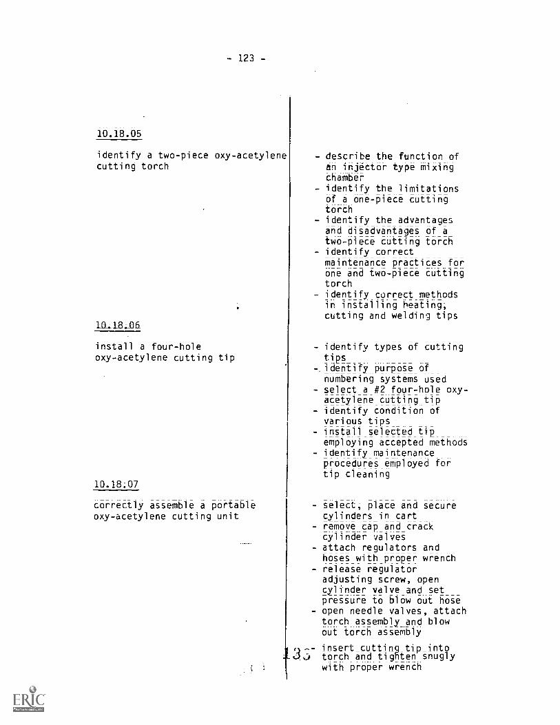
- 123-
10.18.05
identify a two-piece oxy-acetylenecutting torch
10-18;_06_
install a four-holeoxy-acetylene cutting tip
correctly assemble a portableoxy-acetylene cutting unit
- describe the function ofan injector type mixingchamber
- identify the limitationsof a one-piece cuttingtorch
- identify the advantagesand disadvantages of atwo-piece cutting torch
- identify correctmaintenance practices forone and two-piece cuttingtorch
- identify correct methodsin installing heating;cutting and welding tips
- identify types of cuttingtips
-. identify purpose ofnumbering systems used
- select a #2 four-hole oxy-acetylene cutting tip
- identify condition ofvarious tips
- install selected tipemploying accepted methods
- identify maintenanceprocedures employed fortip cleaning
select; place and securecylinders in cartremove cap and crackcylinder valvesattach regulators andhoses with proper wrench
- release regulatoradjusting screw; opencylinder valve and setpressure to blow out hoseopen needle valves, attachtorch assembly and blowout torch assembly
insert cuttiftgtip intotorch and tighten snuglywith proper wrench

124=
immus
correctly light a cutting torch
10.18.09
identify the use of the neutraloxy-acetylene flame in cutting
10.18.10
shut-down the oxy=acetylene unit
134
- employ general and per-sonal safety precautions
- identify tip size andselect appropriate oxygenand acetylene pressures
- test connections for leaksusing appropriate medium
- open acetylene valve ontorch and light withstriker; adjust acetyleneflow until smokedisappears
- open oxygen needle valveuntil complete combustionof acetylene occurs
- identify the types of
flames- identify the temperature
range of an oxidilinflame
- identify the type of flameemployed in oxy-acetylenecutting of plain carbonsteel
- review general safety pre-cautions
- close acetylene needlevalve on torch body
- close oxygen needle valVeon torch body
- close acetylene cylindervalve, open oxygen needlevalve on torch body
- turn out pressureadjusting screw onacetelene regulator thenclose needle valve
- close oxygen cylinder _
valve, open oxygen needlevalve on torch body _
- turn out pressure adjust-ing screw on oxygen
regulator -then closeneedle valve
- coil oxy=acetylene hose on
unit

-125-
10.18.11
identify the six main factorsgoverning oxy-acetylene cutting
10.18.12
identify the metals that can becut with O.F.C. -A process
- identify materialthickness
- determine surfaceconditions
- determine size of cuttingtip
- determine condition ofcutting tip
- assure proper flamesetting and select correctcutting oxygen pressure
- determine speed of travel- identify conditionsdetermining a good qualitycut
- list the ferrous alloysthat cannot be cut
- describe what occurs whennon-ferrous alloys aresubjected to the cuttingtorch
- describe the behaviour ofvarious elements whenexposed to the cuttingprocess
- list the high alloy steelsthat cannot be cut withthe 0.F.C.-A
- identify the ferrousmetals that can be cutwith the 0.F.C.-A process

= 126-
MODULE 10.19 GAS CUTTING O.F.C.- (OXY-FUEL CUTTING - ACETYLENE)
Goal Statements
The learning experiences in this module are designed to:
a. enable the student to become proficient in using gascuttingequipment.
Learning Outcomes
The student should be able to:
10.19.01
cut sheet steel with the 0.F. .-Aprocess
10.19.02
cut mild steel plate with the0.F.C.-A process
Refer to:
Provincial Welding CurriculumLevel "C"Module: P 2Goal 6Performance Objectives #3
Student Activities
- employ general and person-al safety precautionsmark a straight line withscriber, soapstone; chalk-line, or employ centrepunch
= proceed with cuttingemploying correct angleand speednerform specificationcheck and review qualityof cut
- employ general safetyprecautions
- read specifications sheetemploy personal safetyprecautions
- light cutting torchselecting appropriateflame
- proceed with cuttingoperation; employ correctangle and speed
= shut down oxy=acetyleneunit
- perform specificationcheck and review qualityof cut
- follow repeat procedures

-127 -
10.19.03
cut structural sections with the0.F.C.-A process
Refer to:Provincial Welding CurriculumLevel "C"Module: P 2Goal 6Performance Objective #7
10.19.04
cut round stock with the 0.F.C. -Aprocess
Refer to:
Provincial Welding CurriculumLevel "C"Module: P 2Goal 6Performance Objective #8
employ general safetyprecautionsread specification sheet_measure and mark member tobe cut in appropriateplacesemploy_ personal safetyprecautions
= light_cutting torch_selecting appropriateflameidentify sequence ofcutting operationproceed with cuttingoperation employingcorrect angle and_speedthUt dOwn oxy =acetyleneunitperform tpecifiCatiOn_theCk_and review qualityof cut
employ general safetyprecautions
- read specification sheetmeasure and mark selectedpiece of stockemploy personal safetyprecautionslight cutting torchselecting appropriateflameidentify sequence ofcutting opr,'ationproceed with cuttingoperation employingcorrect angle and speedshut down oxy=acetyleneunitperform specificationcheck and review qualityof cut

- 128-
10.19.05
perform bevel cuts on mild steelplate with the 0.F.C.-A process
Refer to:Provincial Welding CurriculumLevel "C"Module P 2Goal 6Performance Objectives #5
10.19.06
pierce holes in mild steel platewith the 0.F.C.-A process
Refer to:
PrOVincial Welding CurriculumLeVel "C" _
Module: P 2Goal 6PerforMance Objectives #6
- employ general safetyprecautions _
- read specification_sheet_- determine degree of_bevei,measure and mark selectedmild steel plate
- employ personal safetyprecautions
- light cutting torchselecting appropriateflame
- identify sequence of
cutting operation- proceed with cuttingoperation employingcorrect angle and speed
- shut down oxy-acetyleneunit
- perform specifitation_check and review qualityof cut
- employ general safetyprecautions
- read specification sheet- determine size of holes,measure and mark selectedmild steel plate
- determine thickness ofmetal, select and installappropriate size cuttingtip
- identify sequence of
piercing operation- employ personal safetyprecautions
- proceed with piercingoperation; employingcorrect starting technique
- perform specificationcheck and review qualityof cut

- 129-
1O 19.87
gouge weldments with the O.F.C. -Aprocess
Refer to:Provincial Welding CurriculumLevel "C"Module P 2Goal 6Performance Objective #9
10.19.08
fit structural members with the0.F.C.A process
= employ general safety pre-cautions
- read specification sheetand obtain weldment sample
- determine width and depthof gouge required
- select and installappropriate size gougingtip
- determine and selectcorrect oxygen andacetylene pressures
- identify sequence ofgouging operation
- employ personal safetyprecautions
- proceed with gougingoperation, employingcorrect starting technique
- stop gouging and restartlost cut
- perform specificationcheck and review qualityof cut
read specification sheetdetermine_type_ofstructural member to befittedmeasure and mark sectionsto be cut in appropriateplaces_allow_for_cutting loss,and identify sequence ofcutting operationproceed with cuttingoperations employingcorrect angle and speedclean cutting surfaces,remove slag and oxidesfit cut members anddetermine quality of cutsperform specificationcheck
135

- 130-
UNIT 11.0 SHIELDED METAL ARC WELDING S.M.A.W.)
General Aim
The student should gain experience using approved practices for thesafe management and operation of arc welding equipment;
MODULE 11.01 FUNDAMENTALS OF ARC WELDING
Goal Statement
The learning experiences in thit module are designed to provideintroductory experiences that will help the student to understandthe filndamentalt of arc welding.
Learnin-g Outcomes Student Activities
The student should be able to:
11.0L01
demonstrate a working knowledge ofbasic electricity as applied toshielded metal arc welding
1L01.02
identify types of arc weldingmachines
11 01._03
demonstrate a working knowledge ofelectrodes
14J
study and discuss:- voltage,_ amperage,current flowcharacteristicsdirectionarflow,ttraight and reversepolarity and effectsof each
- define the_uses of anA.C. transformer
= define the uses of arectifier
= define the uses of anAC/DC rectifier
- define the uses of anelectrical motor generator
- define the uses of anengine driven generator
- identify the types of
covered_arc weldingelectrodes in S.M.A.W.
- study the classificationsystem of carbon steelelectrodes
- identify the application
and _characteristics ofmild steel

-131 -
11AIA4
understand and identify basicjoints and variations in jointdesign
electrodes, i.e.: sizes,diameters
- identify the function ofelectrode coatings
- identify and sketch thefollowing basic joints:
- butt= corner= tee= edge= lap

= 132 -*
MODULE 11.02 ARC WELDING SAFETY
Goal Statment
The_learning experiences in this module are designed to help eachstudent understand the_importance of applying safe practices in the
use of arc welding equipment.
Learning OuttOmet
The student should be able to:
111_.02.01
describe the need and use ofpersonal protective equipment
Student Activities
11.02.02
identify electrical hazards insheielded metal arc welding(.S.M.A.W.)
11.02.03
identify corrective measures toeliminate electrical hazards
11.02.04
explain the effects of arc flashand identify first aid treatment
- identify and discuss theuse of the following:- protective clothing,i.e. boots, gloves,leathers
- welding_helmets- helmet lenses (shade
numbers) _
- flash goggles- hearing protection- extreme hazards ofcontact lenses
- butane lighters
- discuss electric shock andthe effects on the body
- describe the Offectt ofdamaged cables and leads
- identify the cause of
electrical fires
- inspect and repair weldingcables and leadt
- demonstrate correct steps
in maintenance ofS.M.A.W. ma lnet
- select proper -fireextinguisher_forelectrical fires
- importance of a properground connection
- identify and discuss thethree -types of radiation:- ultra violet- infra-red- visible light rays

- 133 -
11;02.05
describe the effects of hot metalburns
11.02.06
describe the effects of inadequateventilation
11;02.07
identify acceptable noise levelsin a welding environment
- discuss burns and thefirst aid treatment forburns:- first degree- second degree- third degree
- identify toxic fumes anddiscuss their effect:
- lead- zinc- cadmium- painted surfaces- ozone (the product of
intense arc amperage)
- discuss and identify theneed for hearingprotection
- study Workers' Compensa-tion Board Handbook,Section 13

- 134 -
MODULE 11.03 ARC WELDING EXERCISES
Goal Statements
The learning experiences in this module are designed to:
a. develop manipulative skills in basic competency of arc welding
(S.M.A.W.); andby demohttrate arc welding techniques_on various types of joints
and weld positions, 1-2-3 groove, fillet, 1-flat, 2-horizontal,
3-vertical.
Learning OuttOmeS Student Activities
The student should be able
11.03.01
strike an arc using the S.M.A.W.process when given the equipment,materials, tools and a proceduresheet
Refer to:
Provincial Welding CurriculumLevel "C"
Module: P 4Goal 11Performance Objective #2
11._03._0?
run beads by applying single_andmultipass stringer beads on 1/4platewhen given the equipment,materials, tools, and a proceduresheet
Refer to:
Provincial Welding CurriculumLevel "C"
Module: P 4Goal 11
Performance Objective #3
= read procedure sheet andselect electrode
= cut andclean M.S. plate= secure plate in flatposition and attach groundselect polarity andamperage welding current)insert electrode instinger, apply personalsafety precautions andstart machinestrike electrode on pre-determined spot on plateusing scratch method
- strike electrode on plateusing tap method
= define the term Stringerbead
= read specification sheet- select materials, weldingmachine and weldingcurrent
- attach ground to plate,insert electrode intostinger and apply personalsafety precautions
- start Welding machine- apply stringer bead- remove slag and spatter- apply second stringer bead
- compare to model- remove slag and spatter

- 135-
11.03.03
weave a bead by producing depositswith the Weave methods when giventhe equipment, materials, toolsand a procedure sheet
Refer to
Provincial Welding CurriculumLe401 "C"
Module: P 4Goal 11Performance Objective #4
11.03-04
produce tack welds when given theequipment, materials, tools and aprocedure sheet
Refer to:
Provincial Welding CurriculumLevel "C"
Module: P 4Goal 11Performance Objective #5
11.0_1;05
arc weld lap joints by followingall the procedures
- apply third stringer bead- compare to model- remove slag and spatter- perform specification
check
- define the term weavemethod of weave bead
- read specification sheet- select materials, weldingmachine and weldingcurrent
- attach ground to plate,insert electrode intostinger and apply personalsafety precautions
- start welding machine- apply filler material inthe screscent weave method
- remove slag and spatter- compare deposit to model- apply second weave beadadjacent to previous passemploying herringboneweave
- remove slag and spatter- compare deposit to model
- define the term tack weld- read procedure sheet- identify and locate M.S.
plate- cut plate, clean metalsurfaces and assureproper fit=up
- assemble and supportplates
- select welding machine andwelding current
- apply tacks in prscribedplaces on joints
- remove slag and spatter- perform specification
check
- read specification sheetand employ general safetyprecautions
- identify and locate plateand electrode
- cut plate, clean metal
surfaces and assure properfit=up_
1 4 5

- 136-
Refer to:
Provincial Welding CurriculumLevel "C"
Module: P 4Goal 11.Performance Objective #6
11.03.06
arc weld a Cornet joint AYfollowing all the procedures
Refer to:
Provincial Welding CurriculumLevel "C"
Module: P 4Goal 11Performance Objective #6
11;03.02
arc weld a tee joint (2F) byfollowing all the procedures
Note: Filler metal - E6012,E6010/11, 5/32" dia. E7018, 1/8"dia;
Refer to:
Provincial Welding CurriculumLevel "C"
Module: P 4Goal 11Performance Objective #6
- employ personal safety
precautions- assemble, support and tackweld plates in prescribedposition
- apply filler material insequence, clean betweenpasses
- final cleaning- perform visualspecification check
- perform destructive bendtest and evaluate
= read specification sheetand employ general safetyprecautions
= identify and locate plateand electrodes
= employ personal safetyprecautions
= cut plate; clean metalsurfaces, tack weld platesin orescribed_position
- apply filler metal insequence, clean betweenpasses
tlinal_cleaning ofcompletedweldment
- perform specificationcheck
- read specification sheetand employ general safetyprecaut'ions
= identify and locate flatbar and electrodesemploy personal safetyprecautions
- cut plate; clean metalsurfaces; tack weld platesin prescribed position
= apply filler material= final cleaningperform visual specifica-tion_check _and evaluate
- perform physical specifi=
cation check and evaluate

- 137-
11.03.08
arc weld a corner_joint (36)vertical down by following all theprocedures
Refer to:
Provincial Welding CurriculumLevel "C"
Module: P 4Goal 11Performance Objective #8
41.03.09
arc weld a tee joint (2F)12.GA.MS. _plate by following allthe procedures
Refer to:
Provincial Welding CurriculumLevel "C"
Module: P 4Goal 8Performance. Objective #8
read specification sheetand employ general safetyprecautions
- identify and locatematerial and electrodescut material to size,clean metal surfaces andassure accurate fit=Upemploy_ personal safetyprecautions_use scrap sheet metal toadjust amperage, selectelectrode _angle-, arclength and speed of travelassemble, support and tackWeld material inprescribed positionstrike electrode in weldjoint, apply filler metalwith single_ pass_
= final cleaning ofcompleted weldment_perform specificationcheck
read specification sheetand employ general safetyprecautions_identify and locatematerial and electrodescut material to_size,clean metal surfaces andassure accurate fit=upemploy_ personal safetyprecautions_use scrap sheet metal toadjust amperage, selectelectrode angle, arc_length_and speed_of travelassemble, support and tackweld material inprescribed positionstrike electrode in weldjoint, apply filler metalwith_single_pass_final cleaning ofcompleted weldMent
- peform specification check
1
- 138 -
11.03.10
art_Weld a lap joint (1F) byfollowing all the procedures
Refer to:
Provincial Welding CurriculumLevel "C"
Module: P 4Goal 11Performance Objective #8
- read specification sheetand employ general safetyprecautions_
= identify and locatematerial and electrodes
- cut material to_size,clean metal surfaces andassure accurate fit=up
- employ personal safetyprecautions
- use scrap sheet metal toadjust amperage, selectelectrode_ angle, arc_length_and speed_of travel
= assemble, support and tackWeld material inprescribed position
- strike electrode in weldjointi_apply filler metalwith_single pass_final cleaning ofcompleted weldmentperform specificationcheck
- 139-
UNIT 12.0 METALLURGY
General Aim
To teach the student the fundamentals of basic metallurgy asapplied to the metal trades.
MODULE 12.01 FERROUS METALS
Goal Statements
The learning experiences in this module are designed to:
a; introduce each student to basic processes used in makingferrous metals,
b; introduce to the student the various types of ferrOut metClt,and
c. help the student acquire sufficient skills to identify andselect the proper types of ferrous metals.
Learning Outcomes Student ActivitiOS
The student should be able to:
12.01.01
introduce basic metallurgy
12.01.02
describe the furnaces used in theprocess of making ferrous metals:
= blast- open hearth= basic oxygen process= electric arc
12.01.03
describe the types of ferrousmetals
- cast- grey- white- malleable
- ductile- steel
- read and study handout onterminology
- discuss the types offurnace and their Products
- discuss the various typesof casts

-140-
12.01.03 (Cont'd.)
- carbon steels= low carbon steel- medium carbon steel
- high carbon steel
- alloy steels- high Speed steel- stainless steel- nickel steel- chromium steel- others
12;01;04
describethe procedures forclassifying and identifyingdifferent types of ferrous metals
= spark test= Society of Automotive
Engineers numbering- American Iron and SteelInstitute numbering
12.01.05
deSCribe the effects of alloyingelementS on the weldability ofsteel
12;01;06
describe mechanical and physicalproperties as applied to theweldability of steel
- discuss the various typesof carbon steels
- discuss the various typesof alloy steels
- discuss and individuallyperform practise tests onsample pieces of ferrousmetals
- describe the elementsaffecting weldability
- identify carbon steelSrequiring pre and postheating to improveweldability
- identify alloy steelsrequiring control weldingheat
= define the causes andeffects of the HeatAffected Zone
- identify and studymechanical properties suchas hardness andmalleability
- identify and studyphysical properties suchas carbon and alloying

141
MODULE 12.02 NON-FERROUS METALS
Goal Statements
The learning experiences in this module are designed to:
a. introduce the student to the various types of non-ferrousmetals; and
b, introduce the student to the skills to identifying andselecting the proper types of non-ferrous metalS for a givenapplication.
Learning Outcomes Student Activities
The student should be able to:
12.02.01
describe the types of non-ferrousmetals
- aluminum- babbitt- brass- bronze- copper- lead- magnesium- nickel- zinc- others
12-02.02
describe the procedures forclassifying and identifyingdifferent types of non-ferrousmetals
- discuss_the various typesof r1,71,1-jferrouS metal s
discuss and identify_samples -of various piecesof non - ferrous metalS

- 142 -
MODULE 12.03 WELDABILITY OF STEELS
Goal Statement
The learning experiences in this module are designed to teach theStudent the heat effects in welding on the weldability of steel.
Learning Outcomes Student Activities
The student should be able to:
12.03.01
understand the influence of heateffectS in welding
- study and discuss heateffects of a single beadarc weld
- to the weld- to the surrounding
base metal- identify the effects of
, electrode size- current- welding speed
= discuss the effect ofatmospheric temperatures(freezing) on welds madeoutdoors

143-
MODULE 12.04 HEAT TREATMENT
Goal- Statements
The learning experiences in this module are designed to:
a. introduce the student to the basic principles of heattreatment, and
b. introduce to the student the methods to determine the hardnessof heat treated metals.
Learning Outcomes Student Activities
The student should be able to
12.04.01
describe the different types ofheat treating methods
- hardening- tempering- annealing- normalizing- surface hardening
- various methods
12.04.02
describe the method to determinethe hardness of a heat treatedmetal
- Brinell method- Rockwell method- others
- discuss and in smallgroups perform heattreating processes onsample pieces of metal
- discuss and in smallgroups perform hardnesstests on heat treatedsample pieces

144-
MODULE 12.05 SHAPES OF METALS
Goal Statement
The learning experiences in this module are deSigned to introduce
the student to the various shapes of metals.
Learning Outcomes Student Activitiet
The student should be able to:
12.05.01
identify various shapes of metals- H-beaM- 1-beaM,- Channel- Rail- Angle- T
- Square- Hexagon- Ottagon- Round- Pipe- Tithing- Bat_- Half Oval- othert
- discuss the various shapesof metals and theirmanufacture

- 145-
UNIT 13.0 POWER SAWS, SHAPERS AND MILLING MACHINES
General Aim
The student should develop a basic_understanding of power saws,shapers, and milling machinet, their nomenclature and safeoperation.
MODULE 13.0 POWER SAWS
Goal Statements
The learning experiences in those module are designed to:
a. enable the student to recognize the various types of powersaws,
b. introduce the student to the nomenclature of power saws; andc. help the student operate a power saw in a correct and safe
manner.
Learning Outcomet Student Activities
The student should be able to:
13.01.01
identify and list various types ofpower saws
- horizontal reciprocating- horizontal bandsaw- vertical bandsaW= cutoff saw
- abrasive_wheel- saw wheel
13.01.02
identify and list the operatingparts of a
- vertical band saw- horizontal reciprocating
- list various types ofpower saws
- list operating parts of avertical band saw
- list operating parts of -ahorizontal reciprocatingsaw

- 146-
13;01;03
adjust and operate a horitontalpower saw in a correct and safemanner
13;01;04
clamp and saw a workpiece to aspecified length
13;01;05
adjust and operate a vertical sawin a correct and safe manner
- adjust and operate ahorizontal saw
saw a workpiece to length
- saw to a layout line
15t;

- 147-
MODULE 13.02 SHAPERS
GoalStatements
The learning experiences in this module are designed to:
a; introduce each student to the nomenclature of the shaper,b. help the student operate the shaper in a correct and safe
manner, andc. enable the_student to shape a component accurately and to
specification.
Learning Outcomes Student Activities
The student should be able to:
13.02.01
identify and list the operatingparts of a shaper
13.02.02
adjust and operate the shaper in acorrect and safe manner
13.02.03
clamp workpiece in place on theshaper table using various toolsand fixtures
- T bolts_= parallels
vice _
- angle plates- strap_clamps- vee blbat- lead haMMer= round bar
13.02.04
shape surfaces square to eachother and to specification
- list operating parts of ashaper
- operate the shaper safely
- clamp a workpiece to thetable
- shape all four sithsblock

- 148-
MODULE 13.03 MILLING MACHINES (VERTICAL, HORIZONTAL)
Goal Statements
The learning experiences in this module are designed to:
a. introduce the student to the nomenclature of the millingmachine;
b. help the student operate the milling machine in a correct andsafe manner, and
c. enable the student to mill a component accurately and tospecification.
Learning Outcomes Student Activitiet
The student should be able to:
11;03;01
identify and list the operatingparts of various types of millingmachines
1301.02
adjust and operate the millingmachine in a correct and safemanner
13;03.-03
clamp a Workpiece on the millingtable using various tools andfixtures as needed
- T7bolts- vice- parallelslead hammerangle plates
= strap clamps= packers- round bar
13.03.04
mount a vise on -the milling table,square with table travel using a
dial indicator and parallel
- list operating parts of amilling machine
- operate the millingmachine safely
- clamp a workpiece to thetable
- dial in a vise

- 149-
13.03.05
identify and list various types ofcutters
13.03.06
select and mountacuttercorrectly and safely
13.03.07
touch on workpiece and zero dials(table)
13.07,08
Mill surfaces square to each otherand to specification
- litt various types ofcutters
- mount a cutter
- touch on and zero dials
- mill all four sides ofblock
1 5 ,)

- 150-
UNIT 14.0 HOT METALS
General Aim
The student will develop an awareheSS_of the_types and
characteristics of hot metal forming in relation to the metal
trades.
MODULE 14.01 TOOLS AND EQUIPMENT
Goal Statement
The learning experiences in this module are deSigned to identify,
select and use the tools and equipment related to hot metal
forming.
Learning Outcomes Student Activities
The student should be able to:
14.01.01
deStribe the types of tools usedin hbt metal forming
= anvils- forging hammers= tongs- vices= fullers- swage blocks- swages
14.01.02
describe the equipment used in hotmetal forMing _
- gas fired forges- drop hammerpresS_forgeSCoal fird_forges
- oil fired forges
- diStuSt the types of toolsused in hot metal forming
- discuss the types Ofequipment used in hotmetal forming

- 151 -
MODULE 14.02 FORGING AND BENDING
Goal_ Statement
The learning experiences in this module _are designed to introducethe student to the operations and procedures involved with forgingand bending hot metalt.
Learning Outcomes Student Activities
The student should be able to:
14.02.01
identify the safety equipment andprocedures dealing with hot metalforming
14.02.02
describe the procedures involvedin bending hot metals
- angle_bending- Circular bendingetc.
14.02.03
illustrate the necessarycalcUlatiOns for bending metals
arts_- circles= L-Angle= radius
14.02.04
draw out a point, change sections,hot twist
- discuss the needs forproper use of safetyequipment and proceduresdealing with hot metalforming
- discuss and, in smallgroups, bend hot metalsample pieces
- discuss and demonstratethe necessary calculationfor bends on flat bar andround metal material/
- forge hot metal workpieces

- 152-
MODULE 14.03 FOUNDRY
Goal_Statemsnt
The learning ;:xperiences in this module are designed to:
a. help e,.1c student appreciate the importance of applying safepractice:. "n the foundry;
. introduce the student to the operations and procedures of afoundry;
c. introduce the student to methods in forming a mold; andd. introduce the student to methods of cleaning a casting.
Learl
The
14.03. L
.2 S Student Activities
e able to:
desc.7ihe thi: equipment used infoundry melting processes
- gas fired furnaceselectric -arc furnaces
14.03.02
identify the safety procedures onproper and_approved safetyequipment fOr_fOundry pouring
- face thieldS= leather or heat resistant
aprons- heat resistant gloves- heat resistant legging- leather shoes- others
14-01._03
describe the various metals usedin the casting process
- aluminum- brass or bronze---- iron- steel- etc.
- discuss and, wherepossible; show the processin operation
- discuss the needs forwearing proper safetyequipment for foundrypouring
- diScuS5 metals for casting
- 153-
14.03.04
identify safety procedures forhandling and_making a pour
- crucibles- pre-heating metals- pouring tongs- others
14.03.05
describe the types of tools usedin foundry work
- riddles- flasks- rammers- slick rind spoon- trowel
- bellows- others
14.03.06
illustrate the different types ofmaterials used for making patterns
= woodmetals
= plaster of Paris- wax- plastic- others
14.03.0
explain_the_use of the differenttypes of patterns used in foundryWork
- solid patterns= split patterns- matched plate patterns
14.03.08
describe the_teChniques used inmaking and finithing a pattern
- discuss and perform ademonstration for properhandling and pouringprocedures
- discuss the use of thedifferent types of tollsused
- discuss the differenttypes of materials usedfor making patterns; theiradvantages and workinglive
- discuss the use and costof different types ofpatterns used
= discuss the problems thatthe pattern maker mustencounter when making apattern
- draft
- Sht.inkaje- etc.

- 154-
14.03.09
demonstrate the !eking of a mold= green_sand= waterless sand- shell_molding
investment
14.03.10
explain sand preparation andcontrol
- refractbrinett- cohesiveness- permeability- collapsibility- moisture content
14.03 U
discuss the use and detign ofcores
14.0312
illustrate the purpose of- gates- risers- sprues- others
14;03;13
illustrate the importance ofpouring temperatures of metals
- pyrometers
1401;14
explain the different methods forcleaning castings
- sand blasting- shot blasting- tumbling
- discuss the uses ofdifferent sand for forminga mold
- discuss the importance of
proper-sand preparation informing a mold
- discuss and make a core
= discuss and in smallgroups use pattern andram up a mold
- discuss melting andpouring temperatures ofmetals
- discuss and in a smallgroup, where possible,demonstrate the differentmethods for cleaning acasting

- 155-
UNIT 15.0 INTRODUCTION TO SHEET METAL
Genera_l_kilm
The student should gain an insight into the scope and demandS ofthe sheet metal trades.
MODULE 15.01 SHEET METAL TRADES
Goal Statements
The learning experiences in thit module are designed to:
a. provide the student with an insight into the sheet metalindustry, and
b. dettribe the qualifications required for entry into the metaltradet.
Learning Outcomes Student ActivitieS
The student should be able t-:
15.01.01
recognize the _special demandsplaced on tradesmen in the varioussheet metal trades
15.01.02
explain and list.the qualifica-tions required for_entry into thevarious sheet metal trades
15.01.03
explain and list the types of workperformed by the various sheetmetal trades in:
blow pipe- ventilation- stainless steelmarine work
- architectural
- study and_dittuts variousaspects of the metaltrades
- visit shops and work, sites(field trips)

- 156-
MODULE 15;02 SAFETY IN THE SHEET METAL SHOP
Goal -Statement
The learning experiences in this module are designed to develop an
appreciation for the special precautions involved in handling plate
and sheet metal; and for the use of specialized machineS related to
sheet metal 'abrication.
Learning Outcomes Student Activitiet
The student should be able to:
15.02.01
properly hoAle thin sheet metaland plate to avoid injury fromedges, burrs and notches
15.02.02
avoid tearing clOthi_ng and shoes__on materialt stacked on floors andbeh-cheS
1502.03
operate all types of shears safelyand properly
15A2.._04
avoid crushing fingers in formi_ng,machines
1._02;05
be aware of the hazards to eyescaused by fluxes and acid cleaningbaths
15.02.06
remove all mushroom heads onimpact tools
15.02.07
illustrate the danger of carryingobjects in pockets
- study and discuss thespecialized problems _
inherent in the materialsand machines used in themetal trades
- grind and remove mushroomheads on rivet sets,groovers, chisels,punches, etc.
i6G

- 157-
MODULE 15.03 COMMON SHEET METALS
Coal Statements
The learning experiences in this module are designed to:
a, enable the student to gain an understanding of thecharacteristics of common sheet metals such as base metals,coated metals and alloys;
b. enable the student to understand and select the appropriatethickness of materials needed according to the correct gaugescnedules; and
c. enable the student to learn the various standard sheet sizes.
Learning Outcomes Student Activities
The student should be able to:
15A3;01
demonstrate a working knowledge ofhot and cold rolled steel, copperand alluminum
15.03.02
understand the need for coatingssuch as galvanized, tin, and terneplate
15.03.03
explain the purpose and uses ofcommon alloys such as aluminum,brass and stainless steel
15.03.04
select sheet stock according tosits, gauge; and composition:
= U.S. Standard gauge forsteels
= the Brown & Sharpe gauge fornon-ferrouS metals
- study and discuss thefinishes on steel sheet,hot _and cold rolled
- study and discuss the_characteristics and usesof copper and aluminumsheet
= study and discuss thevarious coating methodsand uses of coated metals
- discuss how alloyingaffects the characteris-ticsand uses of sheetmetals
- practise selecting sheetaccording to gauge andappearance

- 158-
MODULE 15.04 HAND TOOLS
Goal Statement
The learning experiences in this module are designed to help theStudent identify;_ select, use and maintain the hand tools specificto the sheet metal industry.
Learning OutcomOS Studert ActfvitieS
The student should be able to:
15.04.01
recognize, maintain, and usecorrectly the following handtools:
- scratch awl- tinners and riveting hammers- tin snips- aviation snips- mallets- hole punches- rivet sets- hand groovers- circumference rulers- protractors- layout and testing squares- dividers- compasses- trammels- bevel gauges- bending tongs- pliers- nippers- vice grips- cold chisels and punches- forming stakes and drift
pins- others
- select proper lind t,zitfor specific jobS
- maintain and sharpen han,.:tools as required
1

- 159-
MODULE 15.05 SHEET METAL MACHINES
Goal_Statement
The learning experiences in this modUle are designed to enable thestudent to recognize, use, and maintain sheet metal machinery.
Learning Outcomes Student Activities
The student should be able to:
15;05;101
describe the adjustment, correctuse and maintenance of:
- barfolds- s.tandard and pan_brakes- roll forming machines
_
- squaring shears and circleshears
- Beverly and bench_theart- bending and crimpingmachines
- turning machines- burring machines _
= PitttbUrgh; bUttOn lock, andAcme lock machinet
- others
15.05.02
recognize ineffective or damagedmachinery and initiate necessaryrepairs
= ditcutt, dismantle;service; and set up sheetmetal machinery
- study operations andpractict! skills towardsmaster;, jf sheet metalmachinen!
- discuss methods of bladereplacement and repair ofdamage

- 160=
MODULE 15.06 APPLIED GEOMETRY
Goal Statement
The learhing experiences in this module are designed to help the
student betoMe proficient in practical applied geometry required
for pattern layout.
Learning OuttOmeS Student Activities
The student should be at,le to:
define and name all parts ofgeometric shapes such as:
- squares- rectangles- circles- trianges- pyramids- cylinders- cones
15.06.02Bisect a line or arc
15.06.03diVide a line or circumferenceinto equal parts
15.06.04construct a right angle usingproportions of 3-4-5
15.06.05bisect an angle
15406.06'draw an angle equal to a givenangle
15406.07erect a perpendicular to a line orarc from a point on that line orarc
15406408erect a perpendicular to aline orarc from a point off that line orarc
- learn_the formula forcalculating
perimeterareavolume
Of various geometricalshapes
- use diViders and straightedges to construct andsolve geometric problems15.06.02 to 15.06.16
- learn the definitiOns§relationships and names ofall parts of geometricshapes as:
- squaresrectangles
- circles- triangles- pyramids- cylinders- cones

- 161 -
15.06.09
draw lines parallel and at setdistanCe5 apart using dividers
15.06.10
divide a circle into 12 equalparts
15.06.11
adivide a circle into 16 equalparts
15.06_.12
construct a right triangle withina circle
15.0_6A1
draw an arc through three points
15_.06_.141
find the centre of an arc orcircle
15A5_;15
from a point on a circlecircumference draw a line tangentto the circle
15.06.16
from a point ouiside_of_a circledraw a line tangent to that circle
- solve problems involvinggeometric formulae
1

- 162-
MODULE 12.07 SIMPLE PATTERN LAYOUT
Goal Statements
The learning experiences in this module are designed to:
a; enable the_ttUdent to become proficientin pattern development
bated on flat surfaces and right angles;b; develbp an underStanding of seam and edge treatments as applied
tb Sheet Metal; andc. help the student develop proper layout of notches;
Learning Outcomet Student Activities
The student should be able to:
laJa;o1
develop patterns and fabricateworkpieces involving simple layoutof angular shapes
15.07.02
apply_proper techniques involvingselection, development andfabrication of lap; rivetted,single and double seams, hems andwire edges
15.07.03
develop and_apply notchingtechniques for correct fits
- 16y out and fabricatelight gauge workpiecessuch as boxes, pans,trays, garbage boxes, toolboxet, and wash-=up pans

-163-
MODULE 15.08 PARALLEL LINE DEVELOPMENT
Goal Statements
The learning experiences in this module are designed to:
a. enable the student to become proficient in parallel linedevelopment based on cylinders;
. develop an understanding of seams and edge treatment for asapplied to cylindrical shapes; and
c. help each student understand the importance of proper notchingtechniques.
Learning Outcomes Student Activities
The student should be able to:
15.08.01
develop patterns and fabricateworkpieces involving parallel linedevelopment
15.08.02
apply proper techniques involvingselection, development, andfabrication of lap, rivetted, andgroove single and double seams,hems, and wire edges as applied tocylinders
15.08.03
develop and_apply notchingtechniques for correct fitt
- lay out and fabriCatelight gauge workpieces _
such as cans, pailSi oilmeasurers, elbows, teesand branchet

- 164-
MODULE 15.09 RADIAL LINE DEVELOPMENT
Goal Statements
The learning experiences in this module are deSigned to:
a. enable the student to become proficient in radial line
development in right cones and pyramids;
b. develop an understanding of seams and edge treatments asapplied to conic and pyramid shapes and
c. help the student develop proper notching techniques.
Learning Outcomes Student ActivitieS
The student should be able to:
1509.01
develop patterns and fabricateworkpiece_involVihg radial linedevelopment of round and squarebased objects
15 ;09.02
apply proper techniques involvingselection; developMent andfabrication of lap; riVetted;single and double seams, hemS andwire edges
15._G9;03
develop and apply notchingtechniques for correct fits
- lay_out and fabricatelight_gauge workpiecessuch as pails; funnels,and/or conical, pyramidshaped projects

- 165-
MODULE 15.10 HEAVY GAUGE AND STRUCTURAL FABRICATION
Goal Statements
The learning experiences in this module are designed to:
a. enable each student to become proficient in working heavy gaugesheet and miscellaneous bar, pipe and structural shapes;
b. teach each student to safely handle heavy materials; andc. teach each student to develop patterns making alloWanceS for
metal thickness and inside and outside measurements.
Learning Outcomes Student Activities
The student should be able to:
15;10;01
develop patterns and fabricateworkpieces in heavy sheetinvolving problems of fitt dueto metal thickness
15.10.02
cut, bend,_form, twist, andfabricate jobs using mitcellaneouSsectional shapes
15.10.03
develOp proper techniques forapplying riVtted4 Welded, andbolted to heavy gaugeSheet, bar, and structural shapes
- lay_dut and fabricateworkpieces such as tankS,containers, furniture,guards, railings andWrought iron work

- 1.66 -
UNIT 16.0 GRINDING; POLISHING AND SURFACE FINISHING
General Aim
The students should gain experience in methods of grinding,polishing and surface finishing.
MODULE 16.01 GRINDING MACHINES
Goal Statements
The learning experiences in this module are designed to:
a. introduce the student to the proper use and variousapplications of grinders and sanders, and
b. assist the student to select grinding wheels and belts ofvarious grits and abrasives for particular operations.
Learning Outcomes Stude- --tivities
The student should be able to:
16AL01
demonstrate a working_knowledge obench and pedestal grinders foroffhand grinding
16.01.02
demonstrate a working knowledge oangle grinders using cloth backedand fibre wheels
16.01.03
demonstrate a working knowledge obelt sanders for grinding andsurface cleaning
= sharpen tools- grind edges to a referenceline
- grind welds, remove oxidesand surface finishes
- grind welds, finish edges,remove burrs and oxides,and polish surfaces

-167-
MODULE 16.02 SAFETY PRECAUTIONS
Goal StatementThe learning experiences in this module are designed to emphasizethe safety precautions which must be practised while grinding andpolishing.
Learning Outcomes
16.02.01describe the safe operaticn andmaintenance procedures forgrinders and buffing machines,disk sanders, angle grinders andbelt sanders
S+udent Activities
- study and discuss thefollowing precautions andprocedures:
adequate eye protec-tion
- clothing hazards- tool rest adjustment- suitable guards- work positions in
relation to the wheel,grind up rather thandown
- excessive wheel vib-ration
- clamping devices tohold small work whilegrinding
- heat generated whilegrinding and polishing
- even wheel wear- catching work in wirewheels and buffingwheels
- setting down disksanders on the disk
- flying grit from port-able grinders andsanders
- excessive noise- belts breaking while
in use- getting tangled up indisk sanders and beltsanders
- cracked or chippedwheels and disks andcut belts
= loading the wheel= truing grinding wheels- rotation of wheels andcorrect belt rotation
- always
ge
grind andpolish towards anded

- 168-
MODULE 16.03 BUFFING AND POLISHING
Goal Statmentt
The learning experiences in thiS module are detigned to:
a. teach the student the proper use and various applicationt ofsurface polishing on metals.
b. assist the student to select buffing and polishing processesfor particular applications
Learning Outcomes Student Activities
The student should be able to:
16;03;01
mount and properly use clothbuffing wheels and wire wheels
16.03.02
select buffihg and polishingmaterials and compounds accordingto the type of material and thedegree of polish required eitherby hand or by machine process
- discuss various buffingand polishing processes
- buff and polish metalsurfaces as required

- 169-
MODULE 16.04 PAINTING
_Goal Statements
The learning experiences in this module are designed to:
a. prepare metal surfaces for paint finishes;b. introduce the student to the various types of paint finishes
and application in common use; andc. deve100 an Understanding of safe procedures used in cleaning,
etching, dipping and finish applications;
Learning OUtcomet Student Activities
The student should be able
16.04.01
properly clean and prepare -metalsurfaces for paint finishes
1604 __02
select suitable paints accordingto job requirements
= discuss industrialcleaning, dipping andetching processesclean and prepare metalsurfaces using variousetching and washingmethodS
- discuss various paints andplastic finishes

- 170 -
MODULE 16.05 PLATING AND COLOURING METAL SURFACES
Goal_Statments
The learning experiences in this module are detigned to:
a. introduce the student to the various plating techniquet used inindustry; and
b. give the student an understanding of the use of heat andvarious chemicals to colour metal surfaces.
Learning Outcomes Student Activities
The student should be able to:
16.05.01
outline the different techniquesused in electro= plating and hotdipping
16.05.02
dettribe the use Of heat to colourmetal surfaCeS through variousoxidation rates
16.05.03
select elementary chemicalcombinats or tubttances such asof sulphur tb color metal surfaces
- discuss plating methodsheat treating; and acidand chemical colouringof metals
- plate and colour r
required

171
UNIT 17.0 DRILLING, REAMING, TAPPING
L ener_al_Aim
The student should develop an awareness of the safe operation andsetups of drilling, reaming and tapping procedures.
MODULE 17.0' DRILLING MACHINES
L oal_Statement
The learning experiences in_thit Module are designed to help thestudent become conversant with the different types of drillingmachines.
!_earni.ng Outcomes Student Activities
The student Should be able to:
17.01.01
identify the various types ofdrilling machinet and their uses
17.01.02
identify various parts of drillingmachinet and their u: 2_.
- review notes, textbooksand handouts
- ma'ntain and operateavailable drillingmachines

172-
MODULE 17.02 DRILLING MACHINES
Statements
The learning expericnces in this module are designed to:
a. familiarize the student with the basic theory of drill feedsalid speeds relative to the matorL-11 being drilled,
5. demontrate the correct method of work holding,c. familiarize _the student with twist drills and their holding and
drive MethodS,d. help the Student select tne correct setup for drilling holes,
ande. fai-jliari20 the student with the types and uses of
-countersuit:, ;:ounterbores, circle cutters and reamers.
Learning Oute,7 Student Activities
The student should be able to:
17.02.01
calculate the required R.P,M._whengiven a cutting speed and drilldiameter
apply the correct pressuredepending upon material and drillsize
17.02.03
select the correct vise or workholding device to safely secureworkpiece
- calculate the correctR.P.M._:USing the drillspeed formula
_ _- drill 1-nles within_agivehtolence, using differentdrill diameters
- select from a group c.f
work holding fixtur'es thecorrect device for aspecific application

= 173-
17;02._04
select the correct drill holdingdevice with respect to straiOt ortaper shank
select the correct forvarious dr-Aling operations
17.02.06
recognize the various types ofdrillS
= straight shankstaper shanks
- counterborecountersink
17.02.07
identify various types of drillSize methods
Imperial= S.I. metric= number
letter
mount straight or taperShank drillS actording tojob requirements
- drill - thin metals- deep holes- large holes
- review notes, textbooksand handouts
- review notes, textbooksand handouts

- 174 -
M. JLE 17.03 REAMING
GoA Statement
The learning experiences in this module are designed to familiarizethe student with the types and uses of machine reamers.
Learning Outcomes Student Activities
The student should be able to:
17.03.01
recognize the various types ofreamers
.
straight rlute= helical flute
17.03.02
determine dri'llr.g allowances formachine reaming
17."..1.03
determine speeds feeds for
reaming
17.03.04
ream an accurate hole on the drillpress
- review notes, textbooksand handouts
- calculate drill size forreaming
- calculat eds and feedsfur rean,
- set up a drill press andream a hole

- 175-
MODULE 17.04 TAPS AND DIES
Octal Statement
The learning experiences_in this module are designed to familiarizethe student with taps, dieS and their use.
Learning Outcomes Student Activities
The studel: should be able to:
17.04.01
identify various__ thread systems- metric (I 5 0= Imperial (Unified)= pipe
17.04.02
:--select the correct drill sizefrom a tap drill chart
17.04.03
identify the various types of taps-
010'j
bottoMing= Oipe- straight pipe
17.04.04
identify various types of dies
17-04.05_
tap a hole with a hand tap
ITAA_;_015
thread a rod with a solid oradjustable die
17;34.07
thread and tap pipe fittings withhand threading tool::
review notes, textbooksnd handouts
- study clasioom notes andthe prescribed textdescription
- review notes and handouts
- review notes and handouts
- drill and tap a hole
thread a rod to size
- thread and tap pipe
fittings
133

- 176-
UNIT 18.0 LATHES
General Aim
The student- should develop a basic understanding of types oflatheS, tools and_operations which can be performed; and becomeproficient in hJsiC lathe operations.
MODULE 18.01 LATHE NOMENCLATURE
Goal_ Statement
The learning experiences in this module are designed_to help thestudent become conversant with the different types of lathes andtheir parts;
Learning Outcomes Student Activil :et
The student should be able to:
18.01.01
identify the various types oflathes and uses
18.01.02
identify the various parts of anengine lathe and their uses
- review notes and handouts- shop tour
- review notes and handouts- shop tour

- 177 -
MODULE 18.02 WORK HOLDING
Goal Statement
The learning experiences in this module arc designed to provide theStudent with experiences with various work holding methods,
Learhin.0 OuttOMes
The student should be able tc
18.02.01
identify the following spindlenoses
camloc.k
- threade.1taper and key
- flange
18A2=02
identify the following workholding devices and their uses
univesal three jaw- irCi.pendent four jaw-
- face atedriviny plate
- collets
18.02.03
demonstrate the care and knowledgenecessary to mount chucks on thevarious typos of Spindle noses
18.02.04
mount a workpiece in a universalthree jaw chuck
18.02.05
mount a workpiece in a four jawuniversal chuck
18.02.06
mount work betWeen centres
Student Activities
- review notes and handoutS- shop tour
= review notes and handoutsshop tour
= mount and dismount chuckson various spindle noses
- mount a ,,iorkpiece intv.-ee j.w chuck
mount _a ,tihrkpiece in 6four jav u,Ock
7- wor4iece betweenentre!- usng the correct
dc"c and e.ad centre
pressure

- 178-
MODULE 18.03 LATHE CUTTING TOOLS
Goal St- atement
The learning experiences in this module are designed to familiarizestudents with the various types of high speed steel cutting tools.
Learning Outcomes Student ActiVitieS
18,-03 01-
identify the various shapes ofcutting tools
18.03.02
identify the various tool bitcutting and clearance angles
18.03.03
grind a high speed steel tool bitfor turning steel
- review textbookinformation
- review textbObkinformation and handout
, practice grinding on coldrolled steel beforeattempting to grind a highspeed bit
= 179-
MODULE 18.04 FEEDS AND SPEEDS
Goal Statement
The learning experiences in his module are designed to enable thestudent tr, recognize the need for &fferent feeds and speeds.
Learning Outcomes Student Activities
The student should be able to:
12.04;01
determine factors that affectspeeds and feeds
12;04.02
calculate speed and feedS forbasic lathe operations
- review textbookinformation relating tofeeds and speeds
- review textbook materialsrelating to cutting speedsof metals

- 180-
MODULE 18.05 OPERATIONS
Goal Statement
The learning experiences in this modUle are designed to introducethe student to the basic operations which can be performed on anengine lathe.
Learning Outcomes Student Activities
The student should be able t
18.05.01
prepare a workpiece for mountingbetween centres
18.05.02
turn a cylindrical workpiece
18,05.03
bore a through hole to size
18.05.04
knurl a workpiece for size andappearance
18.05.05
cut a 600 thread
18_;05.06
drill and machine ream a hole
- face and centre drill aworkpiece and mountbetween centres
- set up and turn thecylindrical workpiecepar?'lel
- se s:-. the correct toolsand set up to bore athrough hole
- set up and knurl a:fc,ckpiece
set up and cut a thread
review reaming speeds andoperations in the textbook
- Set up and ream a hole

- 181 -
18.5.07
part off a workpiece
18.05.08
turn a taper using- compound rest- taper attachmentoffset method
- set up and part off aWorkpieCe
- turn three tapers using:- compound rest- taper attachment- offset method

Section ThreeCP 12 Welding and
Plate Fabrication
CAREER P FPARAT ON PROGRAI. .. ... . ...... ... __ _ ____. _ ., _ v. gm. M4 9
E E 11 . PREPARATION PROGRA .... ..'f , . . ,Jp ,4`..
9
_ARFFR prIFPARATIoN -PROGRA......, ... EMMY mi . ., . . ...,.. ,- .., -- ma ow 11. ow .. .. ..
R.EE R.0
EPA,,,e
RA..T. O. P R o G RA.
CAREER PROGRA..
PREPARATION PR ACAREER
OnRitil_ _.PREPARATION PROGRAM
ABEE14
cAFIFFR PRFPARATI PROGRAWIN - II IMO Mk MB NMI.= =.
CAREER.P FPARATION. _
CAREE PREPARATION9 re
7CAREW-PREPARAT10SEER -PREPARATION'
C ER PREPARATION
ROGRAPROGRA._P'PROGRAPROGRA_ _
4ERpREPARAflON PRnriFIACAL "S PREPARATION

r
+1.
o
I

- 185 -
PAGE
SECTION THREE - C P 12 - WELDING AND PLATE FABRICATION . 189
UNIT 1.0 - COOPERATIVE CAREER PREPARATION (COMMUNITY BASED). 190
MODULE 1.01 - PREPLACEMENT ROUTINE . . . . . . . 190
MODULE 1.02 - PLACEMENT (EXTERNAL TO SCHOOL) 192
MODULE 1.03 - POSTPLACEMENT ROUTINE 193
MODULE 1.04 - STUDENT REPORTING PROCESS 194
MODULE 1.05 - LETTER OF THANKS TO EMPLOYER . . . . . 195
UNIT 2.0 - GAS-WELDING OPERATIONS 196
MODULE 2.01 - WELDING SAFETY PRACTICES 196
MODULE 2.02 - STORAGE AND HANDLING OF OXYGEN AND FUELGAS CYLINDERS- 197
MODULE 2.03 - HANDLING AND OPERATING OXY-ACETYLENEEQUIPMENT 198
MODULE 2.04 - ASSEMBLY OF OXY-ACETYLENE EQUIPMENT 199
MODULE 2.05 - TESTING FOR LEAKS- 200
MODULE 2.06 - CORRECTLY LIGHT AND SHUT DOWN THE OXY-ACETYLENE UNIT 201
MODULE 2.07 - TORCH LINE EXPLOSIONS 202
MODULE 2.08 - FIRE PREVENTION 203
MODULE 2.09 - FIRE EXTINGUISHERS 204
MODULE 2.10 - VENTILATION 205
MODULE 2.11 - WELDING AND CUTTING CONTAINERS 206
MODULE 2.12 - PROTECTIVE EQUIPMENT 207

-186-
PAGE
UNIT 3.0 = OXY=ACETYLENE EQUIPMENT 208
MODULE 3.01 OXY-ACETYLENE_WELDING EQUIPMENT PROCESSESAND APPLICATIONS 208
MODULE 3.02 - CONSTRUCTION OF OXYGEN AND FUEL GAS
CYLINDERS 209
MODULE 3.03 - CONSTRUCTION OF PRESSURE REGULATORS 210
MODULE 3.04 - OXYGEN AND FUEL GAS HOSE- 211
MODULE 3.05 - OXY-ACETYLENE TORCHES 212
MODULE 3.06 - MANIFOLD SYSTEMS 213
MODULE 3.07 - SELECTION OF FLAMES 214
MODULE 3.08 - TIP SELECTION AND MAINTENANCE 215
UNIT 4;0 - OXY-ACETYLENE WELDING 216
MODULE 4;01 - WELDING POSITIONS 216
MODULE 4.02 - SELECTION OF FILLER METALS 218
MODULE 4.03 - FOREHAND WELD 219
MODULE 4.04 - BEADING 220
MODULE 4.05 - CORNER JOINT 221
MODULE 4.06 - LAP JOINT 222
MODULE 4.07 - EDGE JOINT 223
MODULE 4.08 - TEE JOINT 224
MODULE 4.09 - BUTT JOINT 225
MODULE 4.10 - FUSION WELD OF CAST IRON 226

- 187-
UNIT 5.0 - OXY-ACETYLENE BRAZE WELDING
PAGE
227
MODULE 5.01 - BRAZE WELDING 927
MODULE 5.02 - BRAZE WELDING - BEADING 230
MODULE 5.03 - BRAZE WELDING = LAP JOINTS 231
MODULE 5.04 - BRAZE WELDING 232
MODULE 5.05 - BRAZE WELDING = MILD STEEL PLATE. . 233
MODULE 5.06 - BRAZE WELDING = CAST IRON 234
MODULE 5.07 - BRAZE-WELDING - DISSIMILAR METALS . . 235
UNIT 6.0 - GAS CUTTING OXY-FUEL CUTTING-ACETYLENE . . . 236
MODULE 6.01 - OXY-FUEL CUTTING - ACETYLENE 236
UNIT 7.0 - SHIELDED METAL ARC WELDING 247
MODULE 7.01 - FUNDAMENTALS OF ARC WELDING(REVIEW) THE ARC WELDINGPROCESSES 247
MODULE 7.02 - ARC WELDING SAFETY 251
MODULE 7.03 - ARC WELDING MACHINES 253
MODULE 7.04 - DISTORTION AND CONTROL 256
MODULE 7.05 - ELECTRODES ?58
MODULE 7.06 - ARC WELDING EXERCISES 261
UNIT 8.0 - AIR-CARBON ARC CUTTING - GOUGING 267
MODULE 8.01 - AIR-CARBON ARC CUTTING 267
MODULE 8.02 - ARC. AIR JOINT PREPARATION 270

-188-
PAGr.
UNIT 9.0 BLUE PRINT READING 273
MODULE 9.01 - LANGUAGE OF LINES 273
MODULE 9.02 - BASIC PROJECTIOMS 274
MODULE 9.03 - DIMENSIONING 275
MODULE 9.04 - STRUCTURAL SHAPES 276
MODULE 9.05 - WELDING SYMBOLS 277
MODULE 9.06 - LAYOUT 280
UNIT 10.0 - RIGGING AND MATERIAL HANDLING 281
MODULE 10.01 - SAFETY REGULATIONS ON RIGGING 281
MODULE 10.02 - MATERIAL HANDLING EQUIPMENT 284
UNIT 11.0 - METALLURGY 285
MODULE 11.01 = FERROUS MATERIALS 285
MODULE 11.02 = PHYSICAL PROPERTIES 287
MODULE 11.0 3 - HEAT TREATMENT 288
SECTION FOUR - RESOURCE MATERIAL 291

-189=
C P 12 - WELDING AND PLATE FABRICATION
General Aim and_Purpose
The primary aim of this grade 12 program is to provide learningexperiences that will help students develop marketable skills orqualify for advanced standing in a related program at a college orprovincial institute. At the grade 12 level,'an integrel part ofthe learning experience involves practical experience in a workingsituation external to the school. This cooperative careerPreparation component involves at least 100 hours of activitiesthat are community based to provide actual work experienceorganized through the cooperation of employers and unionorganizations.
Students should acquire a comprehensive knowledge of:
a. basic requirements for successful employment in the welding andplate vocations;
h. practices necessary for clean, safe and orderly work habits;
c. the characteristics, properties, sizes, gauges and shapes ofvarious sheet and extruded metals used in the fabricationindustry;
d. sketching, pattern development, blueprint reading and appliedmathematics;
the tools and machinery used in industry;
f. fabrication methods used in the various branches ofindustrY;
g. employment opportunities and occupational qualifications neededfor job entry levels;
procedures and opportunities available for continuingeducation; and
i. employers expectations for a positive attitude toward the workethic and good relations in working with others.
197

- 190 -
UNIT 1.0 COOPERATIVE CAREER PREPARATION (COMMUNITY BASED)
General -Aims
The student should:
a. develop an increased understanding of the employment opportuni-ties in the community, province and country;
b. gain practical experience relating to employmentresponsibilities;
c. benefit from the knowledge and experience of resource personsfrom business and industry.
Community representatives should participate in oraanizedactivities connected with the program.
MODULE 1.01 PREPLACEMENT ROUTINE
Goal Statements
The learning experiences in this module are designed to:
a. provide an opportunity for the student to review appropriateregulations of Workers Compensation Board;
b. review all necessary procedures for student transportation toand from a placement work site;
c. increase student responsibility to school and employer;d. acquaint the student with documentation, forms, contracts, and
the reports of employer, teacher, and student.
Learning outcomes Student Activities
The student will be able to:
1.01.01
dress appropriately for the typeof employment experience
1.01.02
describe the transportationprocedures necessary to reachthe job site
- discuss appropriate dressfor different occupations
- consider public or privatemeans

- 191 -
1.01.03
list the important factors relatedto behaviour on the job
- review introductoryprocedures to contactemployersdiscuss nanners, speech,things to observe
= discuss significance ofreports
- read examples of reportsthat will be written bythe employer and theteacher

- 192 -
MODuLE 1.02 PLACEMENT (EXTERNAL TO SCHOOL)
Goal Statements
The learning experiences in this module are designed to:
a. provide the student with experiences that will relate schoolexperiences with actual working conditions;
b. provide students with actual job experience in a workingenvironment;
c. increase student awareness and understanding of employeeresponsibilities;
d. have the student practise increased responsibility within awork environment
e. facilitate effective transition of students between scnool andemployment;
f. assist the student to see value in education and training;g. create a student awareness of the opportunities for further
training.
Learning Outcomes Student Activities
The student will be able to:
1.02.01
function effectively in a jobsituation
1.02.02
work cooperatively with otherstudents or employees
- follow directions mutuallyagreed to by employer andteacher
- ask questions related tocareer goals
- maintain good relationswith others
- acquire trainingexperiences in the com-munity
2u

-193-
MODULE 1.03 POSTPLACEMENT ROUTINE
Goal Statements
The learning experiences in this module are designed to:
a. assist the student to make a job analysis of an occupationrelated to the placement,
b. review employment and career possibilities related to actualjob experiences.
Learning Outcomes Student Activities
The student will be able to:
1-03.01
prepare a job analysis of anoccupation where work experiencewas obtained
1.03.02
list safety factors that must beobserved in a chosen occupation
- review format of sampleanalyses
- discuss career paths
- review safety aspectsrelated to self and others

-194-
MODULE 1.04 STUDENT REPORTING PROCESS
Goal Statements
The learning experiences in this module are designed to:
a. provide students with a format for reporting on their fieldexperience with an employer,
b. examine the role of employee duties in an occupation and relateto particular school experiences,
c. have the student prepare a formal list of contacts andpractical job experiences.
Learning Outcomes Student Activities
The student will be able to:
1_04.01
complete a report of the jobplacement and discuss in detailthe positive (and negative)aspects of the experience
1.04.02
explain the various job advantagesand disadvantages of an occupation
1.04.03
list criteria of satisfactory jobperformances
L.04.04
list criteria of unsatisfactoryjob performances
- review content of reportsand prepare details on thework experience
- prepare an oral report tothe class on theexperience at a job site
- di in n class
- discussions in class
- discussions in class

- 195 -
MODULE 1.05 LETTER OF THANKS TO EMPLOYER
Goal Statement
The learning experiences in this module are designed to provide thestudent with a format for preparing a letter of thanks to employerswho provided work experience.
Learning Outcomes Student Activities
The student will be able to:
1.Q5 01-
organize and write a letter ofthanks to the business firm wherejob experience was obtained
- prepare a draft for theconsideration of theteacher
- type or write a neatletter using correctgrammar
- mail or deliver tobusiness within one weekof return to school

- 196 -
UNIT 2.0 GAS WELDING OPERATIONS
General- -Aim
The student should gain experience using approved practices for thesafe management and operation of gas welding equipment.
MODULE 2.01 WELDING SAFETY PRACTICES
Goal Statements
The learning experiences in this module are designed to:
. help each student appreciate the importance of applying safepractices in the use of gas welding equipment,
b. introduce the student to methods for checking gas weldingequipment before operating on welding or heating tasks,
c. increase student awareness of the characteristics of gases usedfor gas heating and welding operations.
Learning Outcomes Student Activities
The student should be able to
MIA"identify the_Safety regulations - read and discuss Workers'
for gas welding, cutting and Compensation Board-heating to_enSure a safe working Sections 14, 17, 18
environment

-197-
MODULE 2.02 STORAGE AND HANDLING OF OXYGEN AND FUEL GAS CYLINDERS
Goal Statement
The learning experiences in this module are designed to ensure thateach student can safely handle and store oxygen and fuel gascylinders.
Learning Outcomes Student Activities
The student should be able to:
2.02.01
demonstrate the correct storageand handling practices of oxy-acetylene fuel gas cylinders
- identify correct storagepractices for full oxygencylinders
- identify correct storagepractices for emptyacetylene cylinders
- identify correct handlingpractices for full oxygencylinders
- indentify correct handlingpractices for fullacetylene cylinders
- identify correct procedurein removal of defectiveacetylene cylinder fromserviceidentify correct mode oftransporting cylinders inshop
- transport to and storeempty cylinders in storagearea

-198-
MO)ULE 2.03 HANDLING AND OPERATING OXY-ACETYLENE EQUIPMENT
Goal Statement
The learning experiences in this module are designed to enable eachstudent to correctly handle and operate oxy-acetylene equipment.
Learning Outcomes Student Activities
The student should be able to:
2.03.01
describe correct handling andoperative practices for oxy=acetylene equipment
- crack cylinder and purgevalve with appropriatewrench
- identify appropriateregulator to be used
- identify types of threadson acetylene equipment
- describe how an oxygenregulator is set
- describe how oxy-acetylenefuel gas hose is stored
- describe correct method in
purging oxy-ace tyleoe- describe the effect of oil
and grease in contact withoxygen
- describe correct equipmenthandling practices
- describe correct equipmentoperating practices

- 199 -
MODULE 2.04 ASSEMBLY OF OXY-ACETYLENE EQUIPMENT
Goal_Statement
The learning experiences in this module are designed to enable thestudent to correctly and safely assemble oxy-acetylene equipment.
Learning Outcomes Student Activities
The student should be able to:
2.04.01
correctly assemble a portableoxy-acetylene unit
- select place and securecylinders in cart
- remove cap and crackcylinder valves
- attach regulators andhoses with proper wrench
- release regulatoradjusting screw, opencylinder valve and setpressure to blow out hose
- open needle valves, attachtorch assembly and blowout torch assembly
- attach welding or cuttingapparatus to torch bodysecurely

- 200 -
MODULE 2.05 TESTING FOR LEAKS
Goal Statement
The learning experiences in this module are designed to enable thestudent to safely test oxy-acetylene for leaks.
Learning Outcomes Student Activities
The student should be able to:
205_0T
demonstrate correct procedures andmethods in testing for leaks
- describe methods employeain detecting leaks inoxygen and fuel gassystems
*- pressurize oxy-acetyleneequipment and adjustregulator to workingpressure
*- close cylinder valve andobserve high pressuregauge on regulator
*- determine pressure drop,if any
*- apply nondetergent soapsuds with brush to jointsand connections
*- depressurize oxy-acetyleneequipment and makenecessary repair
- repeat * and determineoutcome of repair

- 201 -
MODULE 2.06 CORRECTLY LIGHT AND SHUT DOWN THE OXY-ACETYLENE UNIT
Goal Statement
The learning experiences in this module are designed to enable thestudent to correctly light and safely shut down the oxy-acetyleneunit.
Learning Outcomes Student Activities
The student should be able
2;06;01
correctly light an oxy-acetyleneunit
2.06.02
shut down the oxy-acetylene unitsafely
- employ general andpersonal safetyprecautions
- identify tip size andselect appropriate oxygenand acetylene pressures
- test connections for leaksusing appropriate medium
- open acetylene valve ontorch and light withstrikeradjust acetylene flowuntil smoke disappears
- open oxygen needle valveuntil complete combustionof acetylene occurs to therequired flame setting
review general safetyprecautions
- close acetylene needlevalve on torch body
- close oxygen needle valveon torch body
- close oxygen cylindervalve, open oxygen needlevalve on torch body
- turn out pressureadjusting screw on oxygenregulator, then closeneedle valve
- close acetylene cylindervalve, open acetyleneneedle valve on torch body
- turn out pressureadjusting screw onacetylene regulator thenclose needle valve
- coil oxy-acetylene hose on
unit

=202=
MODULE 2.07 TORCH LINE EXPLOSIONS
Goal Statement
The learning_ experiences in this module are designed to enable theStudent to identify the causes of torch line explosions.
Learning Outcomes Student Activities
The student should be able to:
2.07.01
identify the causes of flashback,backfire and burnback
= describe conditions andcauses for a flashback
- describe conditions andcauses for a backfire
- identify equipmentmaintenance procedures toeliminate explosions
- describe gas speed andspeed of flame propaga-tion
- identify the purpose of areverse flow check valve(RFCV)
- identify cOnditionscausing a burnback

- 203-
(
MODULE 2.08 FIRE PREVENTION
Goal Statement
The learning experiences in this module are designed to enable thestudent to identify the requisites in fire prevention.
Learning Outcomes Student Activities
The student should be able to:
2.08.01
identify the requisites in fireprevention
define the term fireprevention
- describe the welder'sresponsibilities for fireprevention
- describe the employers'responsibilities for firepravention
- describe conditionscreating fire hazards andexplosions
- identify remedies toeliminate fire hazards andexplosions
- identify the importance of
a fire watcher

- 204 -
MODULE 2.09 FIRE EXTINGUISHERS
Goal Statement
The learning experiences in this module are designed to enable thestudent to identify the components of a fire, types of fires, andextinguishers.
Learning Outcomes Student Activities
The student should be able
identify pressurized A,fire extinguishers
, C type = describe the requisitesfor a fire
- describe the types offires
- describe the classes offires
- describe the types of fireextinguishers
- identify the types of fireextinguishers used toextinguish rubbish andpaper fires
- identify types of firescombated with CO2 fireextinguishers
- Identify the uses of A, B,C type fire extinguishers

- 205 -
MODULE 2.10 VENTILATION
_Goal Statement
The learning experiences in this module are designed to give asimulated working environment to enable the student to identifyventilation requirements for welding, cutting and general shopwork.
Learning Outcomes Student Activities
The student should be able to:
identify ventilation requirementsfor welding, cutting and generalshop work
review Section #17,Workers' CompensationBoard Regulations forventilation requirements
- identify conditions thatrequire ventilation
- identify materials thatemit toxic fumes whenheated, welded or cut withtorch
- identify precautionsrequired when working inconfined areas

- 206-
-MODULE 2.11 WELDING AND CUTTING CONTAINERS
Goal Statement
The learning experiences in this module are designed to enable thestudent to identify the correct and safe methods for welding andcutting containers.
Learning Outcomes Student Activities
The student should be able to:
2.11.01
identify the hazards involved inwelding or cutting containers thatare sealed or containers that haveheld combustibles
- study and discuss safemethods of welding orcutting containers
= steam cleaning- purging using inertgases
= filling with water

- 207=
MODULE 2.12 PROTECTIVE EQUIPMENT
Goal Statement
The learning experiences in this module are designed to enable thestudent to select and use protective equipment in welding.
Learning Outcomes Student Activities
The student should be able to:
2.12.01
identify and select properprotective equipment
2.12.02
idehtify_the danger_in the use ofcontact lentet in the shop
2.12.03
identify the danger in butanelighters
- describe the reason forwearing safety glasses
- describe uses and types ofgoggles in welding andcutting
- describe the uses andtypes of welding helmets
- describe the use of tintedor_coloured lenses inwelding and cutting
- identify types of hearingprotection equipment used
- identify the advantages of
using leather jackets inwelding and cutting
- identify the advantages of
using leggings and apronsin welding and cutting

-208-
UNIT 3.0 OXY-ACETYLENE EQUIPMENT
General Aim
The student should identify, understan , and use oxy-acetylenewelding equipment.
MODULE 3.01 OXYGEN AND ACETYLENE GASSES THEIR PROPERTIESAND PRODUCTION
Goal- Statement
The learning experiences in this module are designed to provideintroductory experiences that will enable the student to identify,understand, and use basic oxy-acetylene welding equipment.
Learning Outcomes Student Activities
The student should be able to:
3.01.01
describe the production andproperties of oxygen and acetylenegas
3_01_02
identify other fuel gases used inoxy-fuel gas process
- mapp gas- propane gas- natural gas
- describe the properties ofoxygen
- describe the production ofoxygen
- describe the properties ofacetylene
- describe the production cfacetylene
- describe the properties ofmapp gas
- describe the properties ofpropane gas
- describe the properties ofnatural gas
21

- 209 -
MODULE 3.02 CONSTRUCTION OF OXYGEN AND FUEL GAS CYLINDERS
GoalStatement
The learning experiences in this module are designed to provideintroductory experiences that will teach the student to identify,understand, and use basic oxy-acetylene welding equipment.
Learning Outcomes Student Activities
The student should be able to:
3;02A1
describe the construction ofoxygen and fuel gas cylinders
- state agencies that governstandards in cylinderconstruction
- describe the constructionof an oxygen cylinder
- describe tne function ofthe oxygen cylinder valve
- describe the function ofthe oxygen cylinder valvecover
- describe the constructionOf_ an acetylene cylindervalve
- describe the constructionof a fusible plug and itslocation
- describe the constructionof a mapp gas cylinder andvalve

- 210 -.
MODULE 3.03 CONSTRUCTION OF PRESSURE REGULATORS
Go..11 Statement
The learning experiences in this module are designed to provideintroductory experiences that will enable the student to identify,understand, and use basic oxy-acetylene welding equipment.
Learning Outcomes Student Activities
The student should be able to:
3.-03.01
identify the construction andapplication of regulators onoxy-acetylene equipment
- state purpose of apressure-reducing devicein oxy-acetylene equipment
- describe the constructionof the single and doublestafie regulator
- identify the limitationsof a single stageregulator
- identify the operatingcharacteristics of atwo-stage acetyleneregulator
- identify correctmaintenance procedures forregulators

- 211 -
MODULE 3.04 OXYGEN AND FUEL GAS HOSE
_Goal_Statement
The learning experiences in this module are designed to provideintroductory experiences that will teach the student to identify,undestand, and use basic oxy-acetylene welding equipment.
Learning Outcomes Student Activities
The student should be able to:
3.04.01
identify the correct maintenancepractices for oxygen and fuel gashoses
- describe the constructionof twin design oxygen andfuel gas hose
- identify the colouringscheme employed toseparate oxygen and fuelgases
- identify the thread designemployed in the fuel gashose connector fittings
- identify correct practicesin splicing of oxygen andfuel gas hoseidentify correct practicesin coiling and storingoxygen and fuel gas hoses

-212-
MODULE 3.05 OXY-ACETYLENE TORCHES
Goal Statement
The learning experiences in this module are designed to provideintroductory experiences that will enable the student to identify,understand, and use basic oxy-acetylene welding equipment.
Learning Outcomes Student Activities
The student should be able to:
3.05.01
identify and describe two types ofoxy-acetylene torches
- describe the function of abalanced pressure typemixing chamber
- describe the function ofan injector type mixingchamber
- identify the limitationsof a one-piece torch
- identify correct methodsin installing heating,cutting and welding tips
- identify correctmaintenance practices forone and two-piece torches

-213=
MODULE 3.06 MANIFOLD SYSTEMS
GoalStatement
The learning experiences in this module are designed to provideintroductory experiences that will enable the student to identify,understand, and use basic oxy-acetylene welding equipment.
Learning,Outcomes Student Activities
The student should be able to:
3. 06.03
identify the application of amanifold system
= identify types of manifoldsystems
- identify regulations andstandards governing,construction and operationof manifold systems
- identify and define theterm 'pickled pipe'
- explain the requirementsfor a hydraulic backpressure valve
- identify the purpose ofpigtails and check valves
- identify the purpose of amaster regulator
- identity the advantagesand disadvantages of amanifold system

- 214 -
MODULE 3.07 SELECTION OF FLAMES
Goal Statement
The learning experiences in this module are designed to provide_
inttoduCtOry experiences that will enable the student to identify,
underttand, and use basic oxy-acetylene ,welding equipment.
Learning Outcomes Student Activities
The student should be able to:
3.07.01
identify the use of neutral,oxidizing, and carburizing flamesin oxy-acetylene welding andcutting
= identify the types offlames
- identify the temperatureranges for neutral,oxidizing and carburizingflames
- identify and define the 3Xflame system
- determine the use of 3Xflame
- identify the type of flameemployed in oxy-acetylenecutting and welding ofplain carbon steel

-215-
MODULE 3.08 TIP SELECTION AND MAINTENANCE
Coal-Statement
The learning experiences in this module are designed to provideintroductory experiences that will enable the student to identify,understand, and use basic oxy-acetylene welding equipment.
Learning Outcomes Student Activities
The student should be able to:
3.08.01
identify and select the correctwelding or cutting tip
3.08.02
perform tip cleaning procedure
- identify types of cuttingtips
- identify purpose ofnumbering systems used
- install selected tipemploying accepted methods
- identify condition ofmodels
- identify maintenanceprocedures employed fortip cleaning

- 216 -
UNIT 4.0 OXY-ACETYLENE WELDING (0.A.W.)
General Aim
The student should gain experience using approved practices for thesafe management and operation of oxy-acetylene welding.
MODULE 4.01 WELDING POSITIONS
Goal Statement
The learning experiences in this module are designed to provide thestudent with the letter identification for groove (G) and fillet(F) welds.
Learning Outcomes Student Activities
The student should be able to:
4.01.01
identify the accepted positions ofwelding
4.0L02
identify the five basic joints- A butt- B corner= C tee- D edge- E lap
- review positions ofwelding
- identify the F positions- identify the G positions
- identify and sketch thefive basic joints

217-
4.01.03
identify variations in jointdesign
A - vee buttB - modified cornerC - beveled teeU - prepared edgeE - lap joint slot preparation
4.01.04
identify the standards governingweld sizes and profiles
4;01;_05
identify corrective measure toovercome weld faults
- sketch a single-V buttjoint
- sketch a half open cornerjoint
- sketch a T-joint with adouble bevel
- sketch an edge joint witha single U-edgeveparation
- sketch a lap joint with aslot-weld edge preparation
- describe the ideal filletweld
- identify the term given towelds making a lap, tee orcorner joint
- identify the "actualthroat" on a fillet weld
= identify a welded jointfor fatigue loads
= review handout on weldfaults
= identify 7 types ofstructural discontinuities
- list 5 causes that effectlack of penetration
- list 5 causes that effectlack of fusion
- list 5 causes that givepoor appearance
- list 5 causes that createporosity
- list 4 causes that allowcracks to occur
- identify the causes thatcontribute to undercutting
2
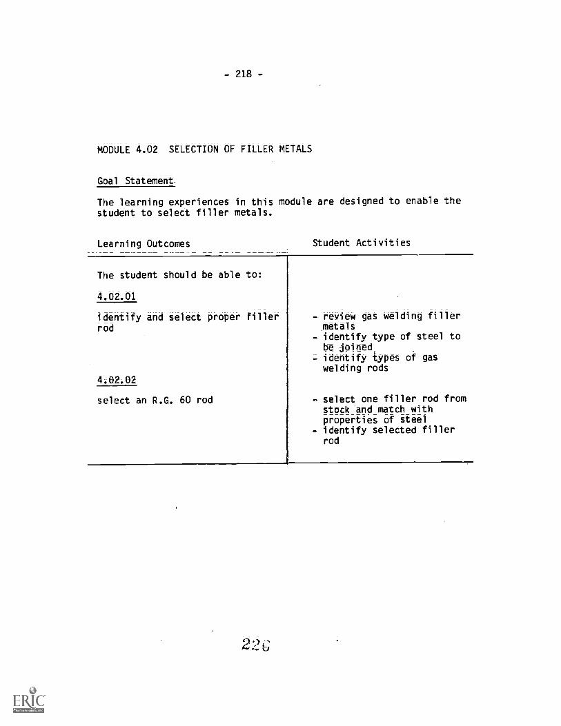
- 218 -
MODULE 4.02 SELECTION OF FILLER METALS
Goal Statememt
The learning experiences in this module are designed to enable thestudent to select filler metals.
Learning Outcomes Student Activities
The student should be able :
4,02A1
identify and select proper Fillerrod
4.02.02
Select an R.G. 60 rod
- review gas welding fillermetals
- identify type of steel tobe joinedidentify types of gaswelding rods
- select one filler rod fromstock and match withproperties of steel
- identify selected fillerrod

- 219 -
MODULE 4.03 FOREHAND WELD
Goal Statement
The learning experiences in this module are designed to enable thestudent to become proficient in using the forehand method ofwelding.
Learnirw Outcomes Student Activities
The student should be able to:
4.03.01
forehand weld with theoxy-acetylene welding process(O.A.W.)
Refer to:
Provincial Welding CurriculumLevel "C"Forehand WeldModule: P 3Goal: #11Performance Objective: #2
- employ general andpersonal safety precau-tions
- select piece of M.S. 1/8"x 6" x 8", remove oxidesand place in flat position
- select tip, install,choose and set correctoxy-acetylene pressuresand light torch
- right handed person, holdtorch with flame pointingto left, lower flame ontoplate
- hold flame 1/16" overplate, preheat and createpuddle
- oscillate torch and movefrom right to left in astraight line holdingtorch at 45°
- review progress and repeatprocedure

220
MODULE 4.04 BEADING
Goal Statements
The learning experiences in this module are designed to enable thestudent to become proficient in bead welding with the O.A.W.process.
Learning Outcomes Student Activities
The student should be able to:
4.04.01
deposit beads with the O.A.W.process
Refer to:
Provincial Welding CurriculumLevel "C"Gas Welding PracticalModule : _P 3
Goal: #11Performance Objective: #3
- read specification sheetand employ general safetyprecautions
- select base metal andfiller materialselect tools and equipmentfor jobdetermine sequence ofoperation and employpersonal safetyprecautions
*- clean metal surfaces andplace metal in flatposition
*- heat to desiredtemperature
*- apply filler metal withthe dipping method andemploy forehand techniquelet cool and performspecification checkrepeat process and follow* tasks

- 221 -
MODULE 4.05 CORNER JOINT
Goal Statement
The_learning experiences in_this module are designed to enablethestudent to Weld a corner joint with the O.A.W. process.
Learning Outcomes
The student should be able to:
4.05.01
fusion weld a corner joint, withthe O.A.W. process in the 3G and46 positions
Refer to:
Provincial Welding CurriculumLevel "C" -
Gas Welding PracticalModule; P 3Goal: #11Performance Objective: #4
Student Activities
- read specification sheetand employ general safetyprecautions
- select base metal andfiller material required
= select tools and equipmentfor job
= determine sequence andposition of operation
- clean metal surfaces,assemble and support partsto be joined
- employ personal safetyprecautions
- heat to aesiredtemperature, tack weld inappropriate places andplace joint into position
- apply filler metal intojoint, employ forehandwelding technique
- let cool and performspecification check
- follow, repeat procedureson handout and follow *tasks.
2 2, ,n)

-222=
MODULE 4.06 LAP JOINT
Goal Statements
The learning experiences in this module are designed to enable the
student to perform a lap weld with the O.A.W. process.
Learning Outcomes Student Activities
The student should be able to:
4.06.01
fusion weld a lap joint with the0.A.W. process in the 3G and 4Gpostions
Refer to:
Provincial Welding CurriculumLevel "C"Module: P 3Goal: #11Performance Objective: #4
- read specification sheetand employ general safetyprecautions
- select base metal andfiller material required
- select tools and equipmentfor job
- determine sequence andposition of operation
- clean metal surfaces,assemble and support partsto be joined
- employ personal safetyprecautions
- heat to desiredtemperature, tack weld inappropriate places andplace joint into position
- apply filler metal into
joint, employ forehandwelding techniques
- let cool and performspecification check
- follow repeat procedureson handout and follow *tasks.
0ij

MODULE 4.07 EDGE JOINT
_Goal Statement
The learning experiences in this module are designed to enable thestudent to fusion weld an edge joint with the O.A.W. process.
Learning Outcomes Student Activities
The student should be able to:
4.07.01
fusion weld an edge joint with theO.A.W. process in the 3rand 4Gpositions
Refer to:
Provincial Welding CurriculumLevel "C"Gas Welding PracticalModule : _P 3
Goal: #11Performance Objective: #4
- read specification sheetand employ general safetyprecautions
- select base metal andfiller material required
= select tools and equipmentfor job
- determine sequence andposition of operation
- clean metal surfaces,assemble and support partsto be joined
- employ personal safetyprecautions
- heat to desired tempera-ture, tack weld in appro-priate places and placejoint into position
- apply filler metal intojoint, employ forehandwelding technique
- let cool and performspecification check
- follow repeat procedureson handout and follow *tasks.
23

224 -
MODULE 4.08 TEE JOINT
Goal Statement
The learning experiences in this module are designed to enable thestudent to fusion weld a tee joint wits* the O.A.W. process.
Learning Outcomes Student Activities
The student should be able to:
4.08.01
fusion weld a tee joint with theO.A.W. process in the 3G and 4Gpositions
Refer to:
Provincial Welding CurriculumLevel "C"Gas Welding PracticalModule : _P 3
Goal: #11Performance Objective: #4
- read specification sheetand employ General SafetyPrecautiors
- select base metal andfiller material required
- select tools and equipmentfor job
*- determine sequence andposition of operation
*- clean metal surfaces,assemble and support partsto be joined
*- employ personal safetyprecautions
*- heat to desiredtemperature, tack weld inappropriate places andplace joint into position
*- apply filler metal intojoint, employ forehandwelding technique
*- let cool and performspecification check
- follow repeat procedureson handout and follow *tasks.

- 225 -
MODULE 4.09 BUTT JOINT
Goal Statement
The learning experiences in this module are designed to enable thestudent to fusion weld a butt joint with the 0.A.W. process.
Learning Outcomes Student Activities
The student should be able to:
4.09.01
fusion weld a butt joint with the0.A.W. process in the 3G and 4Gpositions
Refer to:
Provincial Welding CurriculumLevel "C"Gas Welding PracticalModule: P 3Goal: #11Performance Objectives: #7, 8,
and 9,0111
read specification sheetand employ general safetyprecautionsselect base metal andfiller material requiredselect tools and equipmentfor job
*= determine sequence andposition of operation
*- clean metal surfaces,assemble and support partsto be joined
*- employ personal safetyprecautions
*- heat to desiredtemperature, tack weld inappropriate places andplace joint into position
*- apply filler metal intojoint, employ Forehandwelding technique'et cool and performspecification checkfollow, repeat procedureson handout and follow *tasks

-226-
MODULE 4.10 FUSION WELD OF CAST IRON
Goal_Statement
The learning experiences in this module_are_desi_gned to enable the
student to fUtion weld cast iron using the O.A.W. process.
Learning Outcomes Student Activities
The student should be able to:
4.10.01TETTI-55Weld grey cast iron withthe 0.A.W. process, in the 1Gposition
Refer to:
Provincial Welding CurriculumLevel "C"Gas Welding PracticalModule: P 3Goal: #11Performance Objective #13
4.10-02Tozn7Iii a buttweld on pipe withthe O.A.W. process
Refer to:
Provincial Welding CurriculumLevel "C"Module: _P 3Goal: #11Performance Objectives: #10,
11, and 12
- read specification sheetand employ general safetyprecautions
- bevel joints and assureaccurate fitup of castiron
- clean metal surfaces, as-semble and support castironsear metal surfaces andapply appropriate preheat
- heat cast iron to desiredtemperature
- heat filler metal andapply fluxing agent
- apply heat to attain melt-ing temperatures, add fil-ler metal
- continue fusion welding inthe forehand method andcomplete weld
- let cool to room tempera=ture and perform specifi-cation check.read specification sheetand employ general precau-tionary measures,
= identify and select cor-rect materials
= select tools and equipmentdetermine sequence andposition of operation
- prepare material edges andclean metal surfaces
- assemble and supportmaterials to be joined
- heat to desired tempera-ture, place 4 equidistanttacks and place into posi-tion
- apply filler materialemploying forehand techni=quelet cool and perform
specification check
234

- 227 -
UNIT 5.0 OXY-ACETYLENE BRAZE WELDING
_General_Airm
The student should gain experience using approved practices for thesafe management and operation of oxy=acetylene brazing.
MODULE 5.01 BRAZE WELDING
Goal Statement
The learning experiences in this module are designed to:
a. define the braze welding process,b. identify filler metals,c. identify types of fluxes,d. identify flame type in braze welding, ande. identify types of edge preparations.
Learning Outcomes Student Activities
The student should be able to:
5.01.01
define the braze welding process - read handout- explain what occurs in
liquid-solid phase joining- describe 2 types of
processes- identify the types of heat
required for braze welding- identify correct surfacepreparations in brazewelding
- identify the properties offiller metals in brazewelding
= identify the nature of thebraze bond
235

-228-
5.01.02
identify filler metals
5.01.03
identify types of fluxes
5;01;04
identify flame type used in brazewelding
read handoutidentify type of basemetal to be joinedidentify the mainconstituent metal in acopper base alloy weldingrodidentify the properties ofzinc in the braze weldingprocessidentify a type of fluxused in braze weldingidentify a low fumingbronze alloy in brazeweldingidentify a common type offiller metal used in brazewelding
- read handout- define the term flux- identify types of fluxesand their propertiesidentify two types of fluxemployed in braze weldingidentify the type of fluxon the coated RCUZN-Cfiller metal
= read handout- identify the effect of a
reducing flame in brazewelding
- identify the effect of ahighly oxidizing flame

229=
5.01.05
define the types of edgepreparations
- read handout- describe the nature of thebraze bond
- identify the effect ofsearing
- identify the desired bevelangle in braze welding
= identify the purpose offluted bevels
- identify the effect ofunbroken edges on thebraze bond
231

-230=
MODULE 5.02 BRAZE WELDING - BEADING
Goal Statement
The learning experiences in this_module are designed to provide thestudent with the.opportunity to deposit beads with RCUZN=C fillermetal on M.S. plate.
Learning Outcomes Student Activities
The student should be able to:
5.02.01
deposit beads with RCUZN-C fillermetal on M.S. plate
Refer to:
Provincial Welding CurriculumLevel "C"Braze Welding PracticalModule: P 3Goal: #12Performance Objective: #1
- read specification sheetand employ general safetyprecautions
- identify filler metal andselect base metal
- clean metal surface andemploy personal safetyprecautions
- choose correct O.A. flameand heat base metal todesired temperature
- employ forehand technique,add filler, observetinning action
- proceed to deposit fillermetal

-23I-
MODULE 5.03 BRAZE WELDING - LAP JOINTS
Goal Statement
The learning experiences in this module are designed to provide thestudent with the opportunity to perform braze welds on lap joints.
Learning Outcomes Student Activities
The student should be able to:
5.03.01
perform braze welds on lap jointsin 2F and 3F positions
Refer to:
Provincial Welding CurriculumLevel "C"Braze Welding PracticalModule : P 3Goal: #12 ,
Performance Objective: #2
read specification sheetand employ general safetyprecautions -
select base metal andfiller material requiredselect tools and equipmentfor job
*- determine sequence andposition of operationclean metal surfaces,assemble and support partsto be joined
*- employ personal safetyprecautions
*- heat to desired tempera-ture; tack weld in appro-priate places and placejoint into position
*- apply filler metal intojoint, employ Forehandwelding technique
*- let cool and performspecification check
- follow repeat procedureson handout and follow *tasks
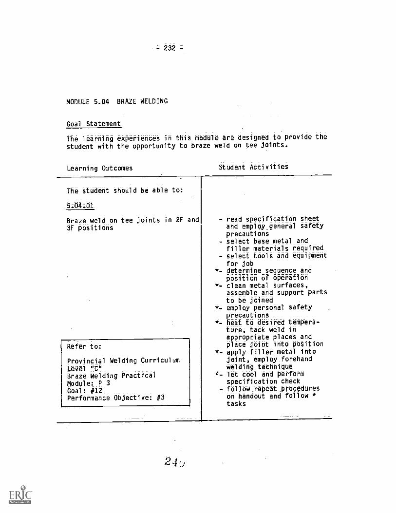
-232=
MODULE 5.04 BRAZE WELDING
Goal Statement
The learning experiences in this module are designed to provide the
student with the opportunity to braze weld on tee joints.
Learning Outcomes Student Activities
The student should be able to:
5.04.01
Braze weld on tee joints in 2F and3F positions
Refer to:
Provincial Welding CurriculumLevel "C"Braze Welding PracticalModule : P 3Goal: #12Performance Objective: #3
- read specification sheetand employ general safetyprecautions
= select base metal andfiller materials required
- select tools and equipmentfor job
*- determine sequence andposition of operation
*- clean metal surfaces,assemble and support partsto be joined
*- employ personal safetyprecautions
*- heat to desired tempera-ture, tack weld inappropriate places andplace joint into position
*- apply filler metal intojoint, employ forehandwelding techniquelet cool and performspecification check
- follow repeat procedureson handout and follow *tasks

=233=
MODULE 5.05 BRAZE WELDING - M.S. PLATE
Goal Statement
The learning experiences in this module are designed to provide thestudent with the opportunity to braze weld to M.S. plate.
Learning Outcomes Student Activities
The student should be able to:
5.05.01
braze weld to M.S. plate
Refer to:
Provincial Welding CurriculumLevel "C"Braze Welding PracticalModule: P 3Goal: #12Performance Objective: #4
- read specification sheet,employ general safetyprecautionsbevel joint and assureproper fitup of plate
- clean metal surfaces,assemble, space andsupport plate
- employ personal safetyprecautions
- heat to desired tempera-ture
- tin joint and proceed tofill groove
- let cool and apply finalcleaning
- perform specificationcheck

-234-
MODULE 5.06 BRAZE WELDING - CAST IRON
Goal- Statement
The learning experiences in this module are designed to provide thestudent with the opportunity to braze weld cast iron.
Learning Outcomes Student Activities
The student should be able to:
5-06.01
braze weld grey cast iron
Refer to:
Provincial Welding CurriculumLevel "C"Braze Welding PracticalModule: P 3Goal: #12Performance Objective: #5
2,1
- read specification sheetand employ general safetyprecautions
- prepare joint and assureproper fitup
- clean metal surfaces,assemble, space andsupport cast iron
- employ personal safetyprecautions
- sear metal or jointsurface and heat todesired temperature
- assure good tinning andproceed to fill groove
- let cool and apply final
cleaning- perform specification
check

- 235 -
MODULE 5.07 BRAZE WELDING - DISSIMILAR METALS
Goal Statement
The learning experiences in this module are designed to provide thestudent with the opportunity to weld dissimilar metals.
Levning Outcomet Student Activities
The student should be able to:
5.07.01
braze weld dissimilar metals
Refer to:
Provincial Welding CurriculumLevel "C"Braze Welding PPacticalModule: P 3Goal: #12Performance Objective: #6
- read specification sheetand employ general safetyprecautions
- prepare joint to givendimensions and assureproper fit-up
- clean metal surfaces,assemble, space andsupport metals
- employ personal safetyprecautions
- sear cast iron surface andpreheat metals
- heat to desired tempera=ture, assure good tinningaction and proceed to fillgroove
- let cool and apply finalcleaning
- perform specificationcheck

-236=
UNIT 6.0 GAS CUTTING 0.F.C.-A. (OXY-FUEL CUTTING - ACETYLENE)
General Aim
The student should gain experience using approved practices for thesafe management and operation of oxy-acetylene cutting equipment.
MODULE 6.01 OXY-FUEL CUTTING - ACETYLENE
Goal_Statement
The learning experiences in this module are designed to provideknowledge and experience that will help the student understand anduse gas cutting equipment efficiently and safely.
Learning Outcomes Student Activities
The student should be able to.
6.01.01
define the oxy-fuel gas cuttingprocess and its application
6.01.02
define and apply terminology usedin O.F.C. -A
6.01.03
identify Workers' CompensationBoard standard governing cutting
= describe hog chemicalreactions generate heatexplain an exothermicreactionexplain an endothermicreactionidentify the mostefficient methods inthermal cutting
- identify the term 0.F.C.-A- read and study reference
material- define the term cutting
attachment
- identify and read Section17 of_Workers' Compensa-tion Board IndustrialHealth and SafetyRegulations

=237=
6-01-04
describe three types of cuttingequipment
6.01.05
identify a two=piece oxy-acetylenecutting torch
6.01.06
identify the six main factorsgoverning oxy-acetylene cutting
- describe manual cuttingequipment
- describe types of portableO.F.C. -A. machines
- list advantages and dis-advantages of portable0.F.C.-A machines
- describe types ofstationary J.F.C. -A.machines
- list advantages and dis-advantages of stationaryO.F.C. -A. machines
- describe the function ofan 41jector type mixingchamber
- identify the limitationsof a one-piece cuttingtorch
- identify the advantagesand disadvantages of atwo-piece cutting torch
- identify correct main-tenance practices for oneand two-piece cuttingtorch
- identify correct methodsin installing heating,cutting and welding tips
- identify materialthickness
- determine surfaceconditions
- determine size of cuttingtip
- determine condition ofcutting tip
- assure proper flamesetting and select correctcutting oxygen pressure
- determine speed of travel- identify conditions
determining a good qualitycut

-238-
6-01.07
identify the metals cutable with0.F.C.-A. process
6.01.08
identify the three types of heattransfer
6.01.09
define contraction
6-01.10
identify the effect of surfacehandening in O.F.C.
- 'list the ferrous alloysthat cannot be cut
- describe what occurs whennon-ferrous alloys aresubjected to the cuttingtorch
- describe the behaviour ofvarious elements whenexposed to the cuttingprocess
- list the high alloy steelsthat cannot be cut withthe O.F.C. -A.
- identify the ferrousmetals that can be cutwith the O.F.C. -A. process
- identify types of
radiation- identify the effect of
heat convection- identify the effect of
heat conductions
- identify the three typesof expansion
- explain volumetricexpansion
- explain restrainedexpansion
- identify free contraction
- select an oxy-acetylenecut piece of mild steel
- describe type of heattransfer occuring duringthe Oxy-Acetylene cuttingprocess
- describe type of coolingocurring once cuttingoperation ceases
- describe the effect of airquenching
- identify the result of
filing on cutting surface
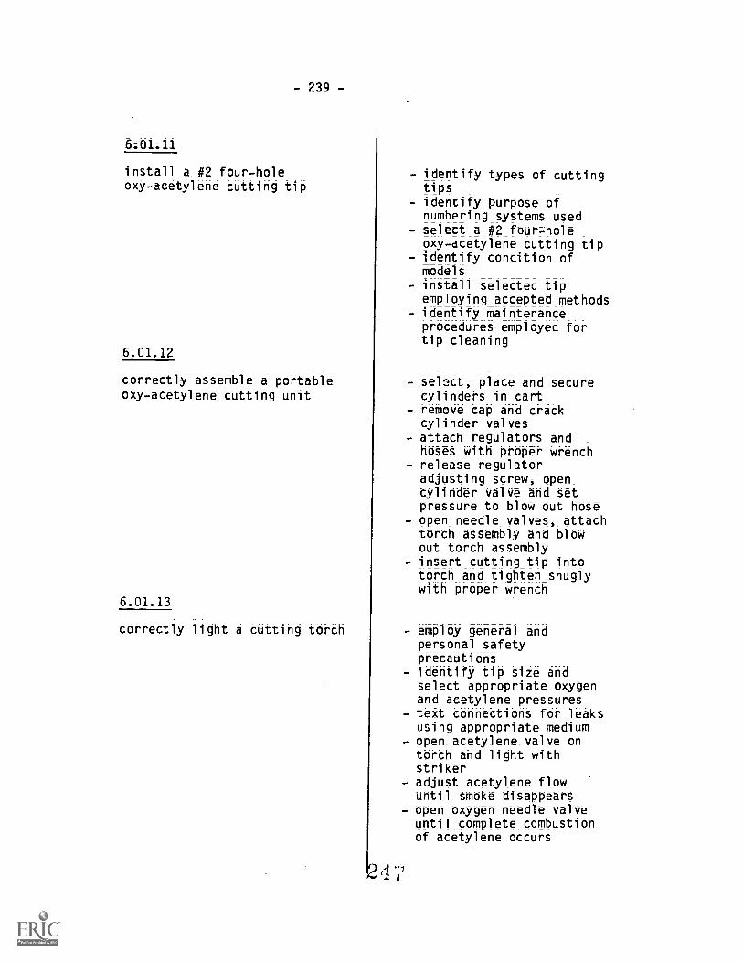
- 239 -
&01;11
install a #2 four-holeoxy-acetylene cutting tip
6.01.12
correctly assemble a portableoxy=acetylene cutting unit
6.01.13
correctly light a cutting torch
- identify types of cuttingtips
- identify purpose ofnumbering systems used
- select a #2 four-holeoxy-acetylene cutting tip
- identify condition ofmodels
- install selected tipemploying accepted methods
- identify maintenanceprocedures employed fortip cleaning
sel3ct, place and securecylinders in cart
- remove cap and crackcylinder valvesattach regulators andhoses with proper wrenchrelease regulatoradjusting screw, opencylinder valve and setpressure to blow out hose
- open needle valves, attachtorch assembly and blowout torch assemblyinsert cutting tip intotorch and tighten snuglywith proper wrench
employ general andpersonal safetyprecautionsidentify tip size andselect appropriate oxygenand acetylene pressures
- text connections for leaksusing appropriate mediumopen acetylene valve ontorch and light withstrikeradjust acetylene flowuntil smoke disappearsopen oxygen needle valveuntil complete combustionof acetylene occurs

- 240 -
6.01.14
identify the use of the neutraloxy-acetylene flame in cutting
6.01.15
shut down the oxy-acetylene unit
6-.01;16
cut sheet steel with the0.F.C.-A. process
Refer to:
Provincial Welding CurriculumLevel "C"Module: P 2Goal: #6Performance Objective: #4
identify the types offlamesidentify the temperaturerange of an oxidizingflameidentify the temperaturerange of an oxidizingflameidentify the type of flameemployed in oxy-acetylenecutting of plain carbonsteel
review general safetyprecautions_,close acetylene_ needlevalve on torch bodyclose oxygen needle valveon torch bodyclose oxygen cylindervalve, open oxygen needlevalve on torch bodyturn out pressureadjusting screw on oxygenregulator, then closeneedle valveclose acetylene cylindervalve, open acetyleneneedle valve on torch bodyturn out pressureadjusting screw onacetylene regulator thenclose needle valvecoil oxy-acetylene hose onunit
employ general andpersonal safetyprecautionsmark a straight line withscriber, soapstone,chalkline, or employcentre punchproceed with cuttingemploying correct angleand speedperform specificationcheck and review qualityof cut

-241 -
6;01-17cut mild steel plate with theO.F.C. -A. process
Refer to:
Provincial Welding CurriculumLevel "C"Module: P 2Goal: #6Performance Objective: #3
6.01.18 _
cut Structural sections with theO.F.C. -A. process
Refer to:
Provincial Welding CurriculumLevel "C"Module: P 2Goal: #6Performance Objective: #7
6.01.1gcut round stock, with the0.F.C.-A. process
Refer to:
Provincial Welding CurriculumLevel "C"Module:_P 2Goal: #6Performance Objective: #8
- employ general safetyprecautions
- read specification sheet- employ personal safetyprecautions
- light cutting torchselecting appropriateflame
= proceed with cuttingoperation employ correctangle and speed
- shut down oxy-acetyleneunit
- perform specificationcheck and review qualityof cut
- follow repeat procedures
- employ general safetyprecautions
- read specification sheet- measure and mark member to
be cut in appropriateplaces
- employ personal safetyprecautions
- light cutting torchselecting appropriateflame
= identify sequence ofcutting operation
- proceed with cuttingoperation employingcorrect angle and speed
- shut down oxy-acetyleneunit
- perform specificationcheck and review qualityof cut
- employ general safetyprecautions
- read specification sheet- measure and mark selected
piece of stock- employ personal safety
precautionslight cutting torchselecting appropriateflame
- identify sequence ofcutting operation
24.Q

- 242 -
6.01.19 (Cont'd)
6.,G1-20
perform bevel cuts on mild steelplate with the 0.F.C.-A. process
Refer to:
Provincial Weld'ing CurriculumLevel "C"Module: P 2Goal: #6Performance Objective: #5
6.01.21
pierce holes in mild steel platewith the 0.F.C.-A. process
Refer to:
Provincial Welding CurriculumLevel "C"Module: P 2Goal: #6Performance jective: #6
25u
- OrOce-9d with cuttingoperat;Oh employingcorrect angle and speed
- shut &own oxy-acetyleneunit
- perform specificationthetk_and review qualityof cut
employ general safetyprecautionsread specification sheetdetermine degree of bevel,measure and mark selectedmild steel plateemploy personal safetyprecautionslight cutting torchselecting appropriateflameidentify senuence ofcutting operationproceed with cuttingoperation employingcorrect angle and speedshut down oxy-acetyleneunitperform specificationcheck and review qualityof cut
employ general safetyprecautionsread specification sheetdetermine size of holes,measure and mark selectedmild steel platedetermine thickness ofmetal, select and installappropriate size cuttingtipidentify sequence ofpiercing operationemploy personal safetyprecautionsproceed with piercingoperation, employingcorrect starting techniqueperform specif;ctioncheck and review qualityof cut
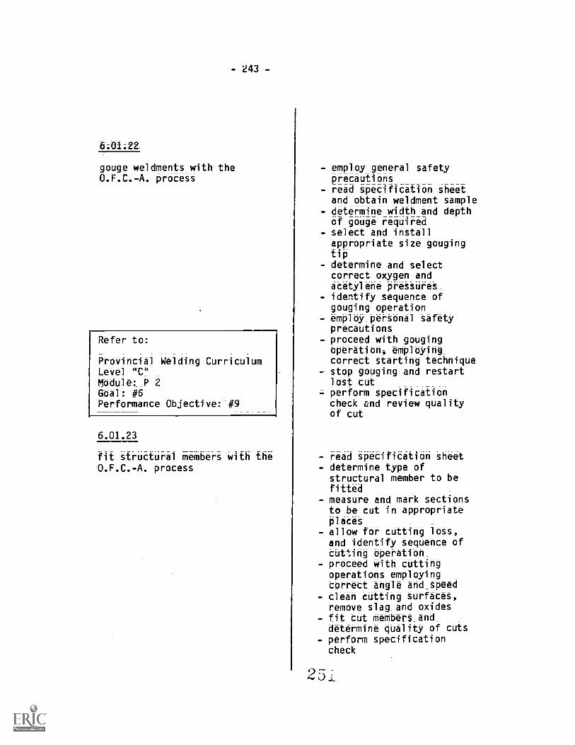
- 243 -
6;01;22
gouge weldments with theO.F.C. -A. process
Refer to:
Provincial Welding CurriculumLevel "C"Module: P 2Goal: #6Performance Objective: #9
6ALaa
fit structural members with theO.F.C. -A. process
employ general safetyprecautionsread specification sheetand obtain weldment sampledetermine width and depthof gouge requiredselect and installappropriate size gougingtipdetermine and selectcorrect oxygen andacetylene pressuresidentify sequence ofgouging operationemploy personal safetyprecautionsproceed with gougingoperation, employingcorrect starting techniquestop gouging and restartlost cutperform specificationcheck and review qualityof cut
- read specification sheet- determine type of
structural member to befitted
- measure and mark sectionsto be cut in appropriateplaces
- allow for cutting loss,and identify sequence ofcutting operation
- proceed with cuttingoperations employingcorrect angle and speed
- clean cutting surfaces,remove slag and oxidesfit cut members anddetermine quality of cutsperform specificationcheck
25 i

=244-
6-01.24
perform a guided cut on sheetsteel with the O.F.C. -A. process
Refer to:
Provincial Welding CurriculumLevel "C"Module: P 2Goal: #6Performance Objective: #11
6.01.25
perform a guided cut on mild steelplate with the 0.F.C.-A. process
Refer to:
Provincial Welding CurriculumLevel "C"Module: P 2Goal: #6Performance Objective: #10
read specification sheetand employ general safetyprecautionsdetermine type of cut anddimensionsmeasure and mark selectedpiece of sheet steelselect guiding tool,prepare and installemploy personal safetyprecautionsproceed with cuttingoperation, employ correctangle, inclination andspeedcomplete cutting operationand perform specificationcheck
read specification sheetand employ general safetyprecautionsdetermine type of cut anddimensionsmeasure and mark selectedpiece of mild steel plateselect guidiug tool,prepare and installemploy personal safetyprecautionsproceed with cuttingoperation employingcorrect angle and speedcomplete cutting operationand perform specificationcheckfollow repeat procedures

- 245 -
6-01.26_
perform a guided bevel cut on mildsteel plate with the 0.F.C.=Aprocess
Refer to:
Provincial Welding CurriculumLevel "C"Module: P 2Goal: #6Performance Objective: #10
6.01.27
perform a precision cut with astraight-line cutting machine
Refer to:
Provincial Welding CurriculumLevel "C"Module: P.2Goal: #7Performance Objective: #1
- read specification sheetand employ general safetyprecautions
= determine degree of bevel,measure and mark selectedmild steel plate
- select guiding tool,prepare and install
- employ personal safetyprecautions
- proceed with cuttingoperation, employingcorrect cutting angle andspeed
- complete cutting operationand perform specificationcheck
- follow repeat procedures
- read specification sheetand employ general safetyprecautions
- determine type of cut,measure and mark selectedmild steel plate
- follow cutting machinemanufacturer'srecommendations and set upof machine on mild steelplate
= employ personal safetyprecautions
= select correct angle andspeed, proceed withcutting operationfollowing machineoperating instructions
- complete cuttingoperation, follow machineshut down instructions
- return cutting machine tooriginal position
- perform specificationcheck

- 246 -
6;0128
perform a precision cut with ashape cutting machine
Refer to:
Provincial Welding CurriculumLevel "C"Module:_P 2Goal: #7Performance Objective: #2
6.01,29
bevel pipe wi th the O.F.C. -A.process
Refer to:
Provincial Welding CurriculumLevel "C"Module: P 2Goal: #7Performance Objective: #3
- read specification sheetand employ general safetyprecautions
- follow machine manufac-turer's instructions onsetup, identify template
- select mild steel plateand set up machine withtemplate
- identify tip size andselect cutting speed
- employ personal safetyprecautions
- proceed with cuttingoperation followingmachine operatinginstructions
- complete cuttingoperation, follow machineshut down instructions
= perform specificationcheck
- read specification sheetand employ general safetyprecautions
- determine degree of bevel,measure and mark length ofselected pipe
- follow cutting machinemanufacturer's recommenda-tions and instructions forsetup and bevellingoperations
- employ personal safetyprecautions-
= select and install correctcutting tip
- proceed with cuttingoperation followingmachine operatinginstructions
- complete cutting operationfollow machine shut downinstructions
- perform specificationcheck
254

- 247 -
UNIT 7.0 SHIELDED METAL ARC WELDING (S.M.A.W.)
General Aim
The student should gain experience using approved practices for andsafe management and operation of arc welding equipment.
MODULE 7.01 FUNDAMENTALS OF ARC WELDING (REVIEW)
THE ARC WELDING PROCESSES
GoaT_Statement
The learning experiences in this module are designed to help thestudent to better understand the fundamentals of arc welding.
Learning Outcomes Student Activities
The student should be able to:
identify the five most common arcwelding processes in industrytoday
7.01.02
describe the application of theS.M.A.W. process in industry today
- review master chart ofwelding processes
- identify arc weldingprocesses
- identify and describetypes of welding performedin the resource industry
- identify and describetypes of welding performedin the ship buildingindustry
- describe the S.M.A.W.process
- define the advantages anddisadvantages of theS.M.A.W. process
- identify the safetyprecautions employed inthe S.M.A.W. process
- describe the type of metaltransfer occurring in theS.M.A.W. process
Cont'd

-248=
7.01._02 (Cont'd)
7.01.03
describe the application of_thegas metal arc welding (G.M.A.W.)and flex core arc welding(F.C.A.W.) process in industrytoday
- describe the type ofshielding atmosphereemployed in the S.M.A.W.process
- identify the types of
filler materials employedin the S.M.A.W. process
- describe the applicationof the S.M.A.W. process inindustry
= describe the G.M.A.W. andF.C.A.W. process
- describe the advantagesand di5advantages ofG.M.A.W. and F.C.A.W.process
- identify the safetyprecautions employed inthe G.M.A.W. and F.C.A.W.process
- describe the types of _
metal transfers availablein the G.M.A.W. andF.C.A.W. process
- identify the types of
sHelding atmospheresavailable in the G.M.A.W.and F.C.A.W. process
- identify the types offiller_metals employed i71the G.M.A.W. and F.C.A.W.processdescribe the appli,Atichof _the F.C.A.W. pro-c.ess A
industry- describe the applicelon__
of the G.M.A.W. process inindustry

- 249-
7.01.04
describe the application of thegas tungsten arc welding( G.T.A.W.) process in industrytoday
7.01.05
describe the application of theshielded arc welding (S.A.W.)process in industry today
describe the G.T.A.W.process
- describe the advantagesand disadvantages of theG.T.A.W. process
= identify the safetyprecautions employed inthe G.T.A.W. process
- describe the type of metaltransfer occurring in theG.T.A.W. process
- describe the types ofshielding atmospheresemployed in the G.T.A.W.process
- identify the types offiller materials employedin the G.T.A.W. process
- describe the applicationof the G.T.A.W. process inindustry
- describe the S.A.W.process
- define the advantages anddisadvantages of theS.A.W. process
.- identify the safetyprecautions employed inthe S.A.W. process
= describe the type of metaltransfer occurring in theS;A;W; process
- describe the type ofshielding atmospheresemployed in the S.A.W.process
- identify the types of
filler materials employedin the S.A.W. process-
- describe the applicationof -the S.A.W. process ininduttry

250-
describe the application of theplasma arc welding (P.A.W.)process in industry today
- describe the P.A.W.process_
- define the advantages anddisadvantages of theP.A.W. process
- identify the safetyprecautions employed inthe P.A.W. processdescribe the type of metaltransfer employed in theP.A.W. process
- describe the type of
shielding atmosphereemployed in the P.A.W.process
.= identify the types offiller materials employedin the P.A.W. process
- describa the applicationof the P.A.W. processindustry
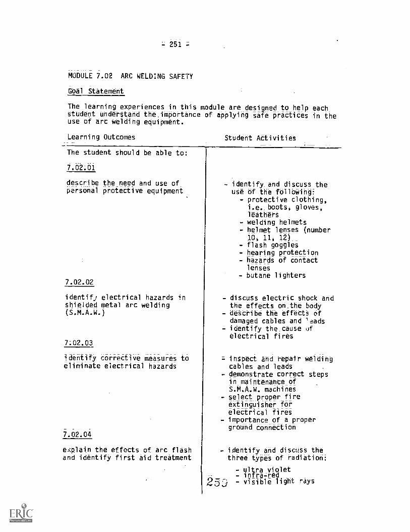
-251=
MODULE 7.02 ARC WELDING SAFETY
Goal Statement
The learning experiences in this module are designed to help eachstudent understand the_importance of applying safe practices in theuse of arc welding equipment.
Learning Outcomes Student Activities
The student should be able to:
7.02.01
describe the need and use ofpersonal protective equipment
7.02.02
identify electrical hazards inshielded metal arc welding(S.M.A.W.)
7.02;03
identify corrective measures toeliminate electrical hazards
7.02.04
explain the effects of arc flashand identify firSt aid treatment
- identify and discuss theuse of the following:
protective clothing,i.e._bOOtt, gloves,leathers_welding helmets
- helmet lenses (number10, 11, 12)
- flash goggles- hearing protection- hazards of contact
lenses- butane lighters
- discuss electric shock andthe effects on the body
- describe the effects ofdamaged cables and 'tads
= identify the cause ofelectrical fires
- inspect and repair weldingcables and leads
- demonstrate correct stepsin maintenance ofS.M.A.W. machines
- select proper fireextinguisher forelectrical fires
- importance of a properground connection
identify and discuss thethree types of radiation:
= ultra violet- infra-red- visible light rays
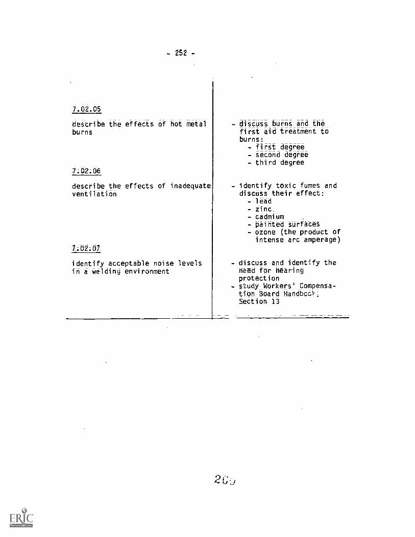
- 252-
7.02.05
describe the effects of hot metalburns
describe the effects of inadequateventilation
identify acceptable noise levelsin a welding environment
- discuss burns and thefirst aid treatment toburns:
- first degree- second degree- third degree
- identify toxic fumes anddiscuss their effect:
- lead- zinc- cadmium- painted surfaces- ozone (the product of
intense arc amperage)
- discuss and identify theneed for hearingprotection
- study Workers' Compensa=tion 3oard Handbcs'f,Section 13

-253-
MODULE 7.03 ARC WELDING MACHINES
.Goal_ Statement
The learning experiences in this module are designed to provide thestudent with a basic understanding of arc welding machinet.
Learning Outcomes Student Activities
The student should be able to:
7.o3Au
describe the principles governingbasic electricity in S.M.A.W.
7.-03;02
identify the methods of generatingand distribution of power inS.M.A.W.
- identify the purpose of ACcurrent
- identify the purposes ofAC current rectification
- identify the purpose ofthe ampere in weldingcurrent
- identify the purposes ofthe volt in weldingcurrent
- detcribe the principle ofmagnetism
= describe the principle ofinduction__
= describe the Offectt ofresistancedescribe how resistance ismeasureddescribe the volt -ampcurve in welding
- identify power sources forarc welding
- identify method ofcontrolling poweridentify types of weldingcurrent
- identify the importance ofthe volt-amp output curveidentify specific loadcurrent and load voltage
- identify_the methods ofdetermining rated currentoutput

- 254 -
7.03 ;03
identify the ground circuitproblems encountered in S.M.A.W.
7.03.04
define the uses of an ACtransformer
7.03.05
define the uses of a rectifier
26
- identify types ofgrounding problems inS.M.A.W.
- identify the effects ofarc blow in the S.M.A.W.process
- identify the causes of arcblow
- identify correctivemeasures to overcome arcblow
= describe the function, of atransformerdescribe or identify theadvantages and disad:ao-tages of an AC transformer
= describe the operation ofa. amperage control
= define the output limita-tions on the model
- identify the usefulness ofthe AC transformer in themarketplace
- describe the function ofthe rectifier
- describe or identify theadvantages of a rectifier
- describe or identify thedisadvantages of a
rectifier- describe the operation of
the current control- identify the output
liMitations on the model- identify_the usefulness of
the rectifier in themarketplace

- 255 -
7.03.06
define the uses of an AC=rectifier
7;03;07
define the uses of an electricalgenerator
7.03.08
define the uses of an enginedriven generator
= describe the function ofthe AC-DC rectifier
- describe or identify theadvantages of an AC-DCrectifier
= descri$-.z or identify thedisadvantages of an AC=DCrectifier
- describe the operation ofthe current control
- identify the outputlimitationi on the model
- identify the usefulness ofthe AC-DC rectifier in themarketplace
- describe the function ofthe electrical motorgenerator
- describe or identify theadvantages of theelectrical motor generator
- describe or identify thedisadvantages of theelectrical motor generator
- describe the purpose ofdual current controls
= identify the outputlimitations on the model
- identify the usefulness ofthe electrical generatorin the marketplace
= describe the function ofthe engine drivengenerator
- describe or identify theadvantages of the enginedriven generator
- describe or identify thedisadvantages of theengine driven generator
- describe the purpose ofdual current controls
- identify the outputlimitationS on the_mOdel
- identify the usefulness ofthe engine_drivengenerator in the
marketplace

-256-
MODULE 7.04 DISTORTION AND CONTROL
Goal_Statment
The learning experiences in this module are designed to provide thestudent with a basic understanding of distortiin control.
Learning Outcomes tiv.;:ot Activities
The student should be able to:
_TA4_;n1
define distortion in welding
7.04.02
identify three common types ofdiStortion
7.04.03
describe six methods of distortioncontrol
- describe theultheating metals
- describe the_resu/ acooling metals
- define expansion- define contraction- describe the effect of:even heating of a metalsurface
- describe the effect ofuneven coding of a metalsurface
= identify dimensionaldistortion in a model
- identify angulardistortion in a model
- identify transversedistortion in a model
- describe the advantages ofproper joint design andedge preparation
- describe the advantagesand disadvantages ofpre-heating the work _
- describe the effect oftravel speed and number ofpasses in welding tocontrol distortion
Cont'd

- 257-
7.04.03 (Cont'd)- describe the advantages of
strong backs and clampingdevices to counterdistortion
- identify the advantagesand disadvantages ofpresetting parts
- describe the effect ofworking around neutralAxis
- describe the advantage offixed or tacked joints tofree moving joints

- 258 -
MODULE 7;05 ELECTRODES
Goal_Statement
The learning experiences in this module are designed to provide thestudent with a sound knowledge of covered electrodes used in arcwelding.
Learning Outcomes Student Activitiet
The student should be able to:
identify the types of covered arcwelding electrodes
7.05.02
apply the classification system ofcarbon steel electrodes
- describe the applicationof non-consumableelectrodes
- identify consumableelectrodes
= identify a covered arcwelding electrode
- identify the types ofcarbon steel covered arcwelding electrodes
- identify a low alloycovered arc weld'ilgelectrode
= identify a mild steelcovered arc weldingelectrode
- identify the use of theprefix "E" in the classi-:-ication process
- describe the meaning of
the first two or threedigits
- describe the importance ofthe second to_last digit
- describe the importance ofthe last digit
- identify the compositionof the_E7024
- identify the_tUrrentcharacteristics of theE7024_-
- identify the weldedproperties of the_E7024
- identify the positions a
E7024 can be welded in

- 259-
7.05.03
identify the application andcharacteristics of mild steelcovered arc welding electrodes
7.05.04
identify the functions of theelectrode coating
- describe the applicationof a fast7freeze electrode
- describe the characteris-tics of aE6010
- describe the applicationof a fast=fill electrode
- describe the characteris-tics of a E7024
- describe the applicationof a fast=follow electrode
- describe the characteris=tics of a E6012
- describe the applicationfor low hydrogenelectrodes
- describe the characteris-tics of a E7018
- identify five separateaspects _in manufacturingelectrode coverings
- identify the function ofdeoxidizers and alloyingelements in the electrodecovering
= identify the_importance ofbinding agents in theelectrode covering
- identify the importance ofarc stabilizer in theelectrode covering_
- identify the function ofslag=forming agents in theelectrode covering
= identify the function ofthe slag deposit on aweldment
(.;

- 260-
7.05.05
describe the generally acceptedmethods of handling and storage oflow hydrogen electrodes
7.05.06
given a simulated field condition,the learner will be able to selectthe correct electrode for the job
- describe the effects ofrough handling of lowhydrogen electrodes
= identify the reason forvacuum packaging ofelectrodes
= describe the effect ofdamaged electrodecontainers
- describe the effect ofmoisture pick=up in a lowhydrogen electrode
- identify one acceptedmethod of storing lowhydrogen electrodes
- identify base metal- identify welding current
available- identify welding position- identify joint design and
fit-up- identify specifications
and service conditions- identify thickness_and
shape_of base metal- identify produCtiOn
efficiencies_- identify environmental
conditions
2

-261 -
MODULE 7.06 ARC WELDING EXERCISES
Goal- Statement
The ',earning experiences in this module are designed to equip thestudent with basic skills in arc welding.
Learning Outcomes Student Activities
The student should be able to
7.06.01
arc weld tee joints in thevertical up technique; vertical(3F) position, following all the.procedures
Refer to:
Provincial Welding CurriculumLevel "C"Module: P 4Goal: #11Performance Objective: #10
- read specification sheetand employ general safetyprecautions_ _
= identify and locate flatbar and electrodes
- cut plate. clean -metalsurfaces and employpersonal safetyprecautionsuse scrap plate to adjustamp, select electrodeangle, arc length andspeed of travel
- tack weld plate inprescribed position
- strike electrode in weldjoint and apply fillermetal in sequence, cleanbetween passes
- final cleaning ofcompleted weldment
- perform specificationcheck
- follow repeat procedures,employ tasks #1 - 8 ofthis InstructionalObjective #2
2 b

-262=
7.06.02arc we d tee joints in theoverhead (4F) position, followingall the procedures
Refer to:
Pt.ovincial Welding CurriculumLevel "C"Module : P 4Goal: #11Performance Objective: #12
7.06.03
arc weld 12 gauge butt joints invertical (3G) position; overhead(4G) position, following all theprocedures
2
- read specification sheetand employ general safetyprecautions _
- identify and locate flatbar and electrodes
- cut plate, clean_metalsurfaces and emplo3 per-sonal safety precautions
- use scrap plate toamp, select_electrodEangle, arc length andspeed of travel
- tack weld plate in pre=scribed position
- strike electrode_in Weldjoint and apply fillermetal in sequence, cleanbetween passes
- final cleaning of complet-ed weldment
- perform specificationcheck
- follow repeat procedures,employ tasks #1-8 ofInstructional Objective #2
- read specification sheetand employ general safetyprecautionsidentify and locate mater-ial and electrodes
- cut material to size,clean metal surfaces andassure accurate fitup
- employ personal safetyprecautions
- use scrap sheet metal toadjust amperage, selectelectrode angle, arclengtn and speed of travel
- assemble, support and tackweld material in prescrib-ed position
- strike electrode in weld_joint, apply filler metalwith single pass_
- final cleaning of complet-ed weldments
- perform specificationcheck
- follow repeat procedures,
employ task #1 - 9 ofInstructional Objective #1

- 263 -
-7-06-04
arc weld 12 gauge corner joints invertical (3G) position; overhead(4G) position, following all theprocedures
7.06.05
arc weld 12 gauge tee joints invertical (3G) position; overhead(4G) position, following allprocedures
- read specification sheetand employ general safetyprecautions
- identify and locatematerial and electrodescut material to size,clean metal surfaces andassure accurate fitup
- employ personal safetyprecautions
- use scrap sheet metal toadjust amperage, selectelectrode angle, arclength and speed of travel
- assemble, support and tackweld material inprescribed position
- strike electrode in weldjoint, apply filler metalwith single pass
- final cleaning ofcompleted weldment
- perform specificationcheck
- follow repeat procedures,employ tasks #1-9 ofInstructional Objective #2
- read specification sheetand employ ger,eral safetyprecautions
= identify and locatematerial and electrodes
- cut material to size,clean metal surfaces andassure accurate fitup
= employ personal safetyprecautions
- use scrap sheet metal toadjust amperage, selectelectrode angle, arclength and speed of travel
- assemble; support and 4-ackweld material inprescribed position
- strike electrode in weldjoint, apply filler metalwith single pass
- final cleaning of
completed weldment

7.(.5.05
-7-.06A6
arc weld 12 gauge lap joints invertical (3G) position; overhead(4G) position, following all theprocedures
7.06-07
arc weld single V-butt joints on3/8 mild steel plate in allpositions 1, 2, 3, 4, G, followingall the procedures
Refer to:
Provincial Welding CurriculumLevel "C"Module: P 4Goal: #11Performance Objective: #12
2
- perform specificationcheck
- follow repeat procedures,employ task #1-9 ofInstructional Objective #3
- read specification sheetand employ general safetyprecautions
- identify and locatematerial and electrodes
- cut material to size,clean metal surfaces andassure accurate fitup
- employ personal safetyprecautions
- use scrap sheet metal toadjust amperage, selectelectrode angle, arclength And speed of travelassemble; support and tackWeld material inprescribed position
- strike electrode in weldjoint, apply filler metalwith single_pass
'1 cleaning of,eted weldment
- ptrform specificationcheck
- follow repeat procedures,employ tasks #1-9 ofInstructional Objective #4
- read specification sheet- identify and locate plateand electrodes_
- bevel plate, clean metalsurfaces and assure properfit-up
- assemble, support and tackweld plate in prescribedposition
- apply filler material insequence, clean between
passes _
= final cleaning= perform visual specifica-tion check
- cut coupons and performdestructive bend test

7265-
7.064_08
arc weld single V-butt joints on3/4 mild steel plate in allpositions 1, 2; 3, 4, G, followingall the procedures
7 Of 09
arc weld V-butt joints in 2Gposition on 4" schedule 40 pipe,American Society for TestingMaterials (ASTM) A120 or A53 gradeB, following all the procedures
read specification sheetidentify and locate plateand electrodesbevel plate, clean metalsurfaces and assure properfitupassemble, support and tackweld plate in prescribedpositionapply filler material insequence, clean betweenpassesfinal cleaningperform visualspecification checkcut coupons and performdestructive bend testfollow procedure sheetsA-D, employ tasks #1-8 ofInstruction Objective #2
read specification sheetidentify and locate pipeand electrodebevel pipe and clean metalsurfaces, assure properfitupassemble, support and tackweld pipe in 2G positionapply filler material insequence, clean betweenpasses. Employ stringerbead techniquefinal cleani;Aperform specificationcheck, visual anddestructive bend test

- 266 -
arc weld V-butt joints in 5Gposition on 4" schedule 40 pipeASTM A120 or A53 grade B
- read specification sheet- identify and locate pipeand electrode
- bevel pipe and clean metalsurfaces, assure properfitup
- assemble, support and tackweld pipe in 5G position
- apply filler material insequence, clean betweenpasses. Employ stringerof weave method
- final cleaning- perform specificationcheck, visual anddestructive bend test

-267=
UNIT 8.0 AIR-CARBON ARC CUTTING (A.A.C.) - GOUGING
General Aim
The student_ thoUld develop knowledge and approved techniques in theuse of Air-Carbon Arc process.
MODULE 8.01 AIR=CARBON ARC CUTTING
Goal Statements
The learning experiences in this module are designed so the studentwill be able to:
a. define the A.A.C. process and its application,b. understand definitions and correct usage of terminology in
A.A.C.,c. understand and apply safety precautions in A.A.C.,d. identify and select equipment and consumables for A.A.C.
process
Learning Outcomes Student Activities
The student should be able to:
BALM_
describe the application_of theA.A.C. process in industry
8.01.02
apply correct terminology inA.A.C.
8.01.03
identify the tyres- of powersources used in A.A.C.
define the A.A.C. processidentify the advantagesand disadvantages ofA.A.C.identify the applicationof A.A.C. in industry
- read handout and referencematerialcompare the terms used inthis module with '.3ndout
- identify the te:-: A.A.C.- define the term eiectrode
= identify the advantages ofconstant current D.C.welding machines in A.A.C.
- ideotify the limitationsof an A.C. power source
for A.A.C.
: ,)

= 268-
8.01.04
identify a D.C. copper coatedelectrode
8.01.05
identify the air pressure r..luiredwith a 1/4" electrode
identify the correct welding leadsize for 200 amp A.C. crrent
8.01.07
identify an air cooled manualelectrode holder
M1.08
identify the advantages of A.A.C.'ccording to handout
- identify the applicationOf the D.C. plainelectrodes_
- identify the application_Of the A.C. copper coatedelectrodes_
- identify the application_Of D.C. copper coatedelectrodeS
- identify type of useidentify minimum insidediameter of air hose formanual cutting
- identify air pressurerequirements in A.A..
- review -table for variouscurrents and lengths
- identify reas forincreased Si7 weldinglead in A.G.
- describe the types ofmechanized torches
- identify the purpose ofthe rotating head in amanual torch
- identify the limitationsof the A.A.C. process
- compare other cuttingprocesses with A.A.C. forsevering of metals
= identify the economicalfeatures of A.A.C.
- identify the versatilityof -the A.M. process
- identify the quality ofcutting surfaces,

- 269-
8;01;(19
identify four types of operatingtechniques
iaentify the safety precautionseMOloyed in
8.01.11
identify z.o;utions to problems inA.A.C.
9
= define the terms gougilsevering, washing andbeveling
= describe the manualgouging process
= identify operatingconditions in gouging
- describe the severingprocess
- describe the washingprocess
- describe the bevelingprocess
identify correctprotective clothingidentify ventilationrequirements in A.A.C.
- identify the need forhearing protection inA.A.Cidentify_precautions toreduce fire hazardsdescribe measures toeliminate electricalhazardt
= identify the cause oflarge carbon deposits atbeginning_of groove
= identify the_cause of anerractic groove with thearc wandering from side toside
- describe the effect ofslow travel speed
- identify the cause of anunsteady arc
- describe the problems anunsteady cutting operationmay encounter
- identify the problemencountered with law airvolume

- 270 -
MODULE 8.02 ARC-AIR JOINT PREPARATION
Goal Statements
The learning experiences in this module are designed to:
a. prepare weld joints on cast steel, cast iron, low carbon steeland high alloy metals,
b. perform weld preparations for repair
Learning Outcomes Student Activities
The student should be able to:
8.02.01
gouge groo.., in cayt steel withthe A.A.C. process
- read specification sheetand employ general safetyprecautions
- locate and identifymaterials
- select and identifycapacity of weldingmachine and welding leads
- identify current an6electrode to be used,select appropriate
- asseniale cutting torch andselect appropriate airpressure and air volume
- employ personal safetyprecautions
- place ground connect!on,insert electrode intoholder start weldingmachine
- identify location of areato be gouged
- proceed with gougingprocess as planned
- complete gouging operationand perform specificationcheck

-271 -
gouge grooves in cast iron wit:,the A.A.C. process
Refer to:
Provincial Welding CurriculumLevel "C"Module: F 5Goal: #5Performance Objective: #3
8.02.03
remove weld faults with theA.A.C. process
Refer to:
Provincial Welding CurriculumLevel "C"Module: P 5Goal: #6Performance Objective: #1
- read specification sheetand employ gen,aral safetyprecautions
= locate and identifymaterial
= select_andidentifycapacity of weldingmachine and welding leads
- identify current andelectrode to be used,select appropriateamperage
- assemble cutting torch andselect appropriate airpressure and air volume
- employ personal safetyprecautionsplace and secure groundconnection; insertelectrode into holder;start welding
- identify l'...cation of areaand depth to be gouged
- proceed with gougingprocess as planned
- complete gouging operationand perform specificationtheCk
- read specification sheetand employ general safetyprecautionsidentify position andextent of weld fault
- employ tasks #3-5,Instructional Objective#1, Unit 8
- Employ personal safetyprecautions
- place and secure groundconnection; insertelectrode into holder;start welding machine
- identify correct sequencein removal of weld fault
- proceed with gougingprocess' as planned
- complete r!.c,ug.fc operationand pecform
check
2

- 272 -
8.02.04
bevel mild steel plate with theA.A.C. process
- read specifitatiOn Sheetand employ general safetyprecautions
- position material*identily degree of bevel
- employ personal safetyprecautionsidentify sequence inbevelling operation
- select correct stance andallow for body movement
- proceed with bevellingoperation
- complete bevelling andperform specificationcheck

-273-
UNIT 9.0 BLUE PRINT READING
General Ma
The student will develop skills to sketch, read and interpretworking drawings as applied to the welding industry.
MODULE 9.01 LANGUAGE OF LINES
Go_al Statement
The learning experiences in this module are detigned to:
a. increase the student's ability to develop and interpret basicdrawings,
b. to understand the language of lines in drawing.
Learning Outcomes Student Activities
The ttudert will be able to:
9.01.01
i.ientify and draw basic lines
9.01;02
identify and draw the sectionlines used to show metals
identify and draw anobject lineidentify and draw a hiddenlineidentlfy and drawextension and dimensionlines
- identify and draw a leader- identify and draw a
cutting plane line- identify and draw a shortbreak line
- identify and draw a longbreak line
- describe the purpose ofsection lines
- identify the methods usedto develop section lines
- identify the section linesused to show cast iron
2 8

-274-
MODULE 9.02 BASIC PROJECTIONS
Goal _Statement
The lr : :rning experiences in this module are designed to help thestudent to understand basic projections.
Learning Outcomes Student Acivities
The student will be able to:
9.02.01
identify baSic projections
9.02.02
understand the development ofviews and sections
- identify the applicationof isometric drawings_
- identify the applicationof obi_que drawings _
= identify the_ applicationOr orthographic projection
= defin the termorthographic projection
= describe the planes ofprojection-
= identify the principlt ofprojection
- identify the methods inplacing views
- develop three views of acube
- identify the applicationof auxiliary views
- develop a drawing showinga half section

- 275-
MODULE 9.03 DIMENSIONING
Gaal_Statea;_e_ht
The learning experiences in this module are designed to enable thestudent to apply .rid understand standard methodS of dimensioning.
Learning Outcomes Studert ActivitiOS
The student should be able to:
9.03.01
apply standard methods ofdimensioning
- describe the purpose ofdimensioning
- describe the elements ofdimensioning
- identify the system ofdimensioning
- identify the principles ofdimensioning
- identify the step:.employed in dimensioning
- employ the tase linemethad_bf dimensioning
- identify the scale S;ze ofa drawing
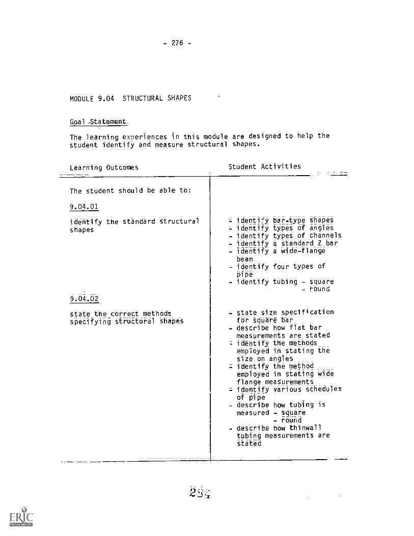
- 276-
MODULE 9.04 STRUCTURAL SHAPES
Goal -St a tement
The learning experiences in this module are designed to help thestudent identify and measure structural shaibeS.
Learning Outcomes Student Activities
The student should be able to:
identify the standard structuralshapes
9.04.02
state the correct methodsspecifying structural shapes
= identi.75, bar-type shapes= identify types of angles- identify types of channels- identify a standard Z bar- identify a wide-flange
beam- identify four types of
pipe- identify tubing - square
- round
- state size specificationfor square bar_
- describe how flat barmeasurements are stated
- identify the methodsemployed in stating thesize on angles
= identify the methodemployed in stating wideflange measurements
= identify various schedulesof pipe
= describe how tubing ismeasured - square
- round- describe how thinwall
tubing measurements arestated

-277--
MODULE 9.05 WELDING SYMBOLS
Goal Statement
The learning e iences in this module are designed to familiarizethe student ding symbols and their significance;
Learning Outcomes Student Activities
The student should be able to:
9,.05;01
identify the basic welding symbols
9.05.02
identify the placement of filletwelds
- review handout and _
American Welding_ Societychart_of standard weldingsymbol'
- describe the signifi-ariceOf the basic weldingsymbol
- identify the significanceof the basic welding_symbol an its elementsidentify supplementarywelding symbolsidentify locationsignificance of basicwelding symbolsidentify preferred symbolsidentify contour andfinish symbolsidentify the placement ofadditional information
- describe how size andlength of fillet weld isindicated in the weldsymbol
- identify the methods used_to_determine the extent ofwelding
- idertify_the method use..to describe chain andstaggered intermittentwelding
- identify the_placement of
contour and finiShspecifications

-278-
9.05.03
identify the placement groovewelds
9.05.04
identify the application_ofbacking and melt - -thru weldS
9.05.05
identify the _application (-and slot Welds
-9,;0506
identify the application of thesurfacing weld symbol
= identify seven types ofgroove welds
= identify how the size ofgroove welds is indicated
- describe how the effectivethroat of a groove weld isindicated-
- describe the placement ofrootopening specifica-tions
- identify the placement ofcontour and finish sOeci-fications
- des-cribe the placement ofgroove angle specifica-tions
- describe the applicationof a back or backing weld
- describe the applicationof a melt-thru weld
- identify the placement ofcontour and finish symbols
identify symbol used toindicate slot and plugwelds
- identify the applicationof slot and pl'g welds
- describe how size of plugand slot welds isindicated
- describe the_placement ofcontour and finiShing_symbols on plug and slotwelds
- identify the surfacingweld symbol
- identify how width andlength is determined for asurfacing weld
- identify how the amount ofbuildup is shown with thesurfacing weld symbol
- identify the application
of the surfacing weldsymbol

- 279 -
9.05.07
identify the application of flangeand flare joint weld symbolt
- identify the flange weldsymbol_
- determine the differencebetween a_corner and edgefiange_weld
= identify how a flange Iti;idis dimensionei
= identify_the cation:of the flange weld symbol

= 280=
MODULE 9.06 LAYOUT
Goal Statement
The learning experiences_in this module are designed to give thestudent experience in full scale layout.
Learning Outcomes Student Activities
The studen- should be able to:
develop a layout to givendimensions
- identify the components ofa detail drawing__
- identify the_appliCatiOnof an assembly drawing
- prepare a print thoWingall criteria
- prepare material litt- select materials- identify and select
necessary layout tools- proceed with layout in
sequence= perform specificationcheck
2S8

-281-
UNIT 10.0 RIGGING AND MATERIAL HANDLING
General Aim
The student should be familiar with safe practices in rigging,staging and material handling
MODULE 10.01 SAFETY REGULATIONS ON RIGGING
Goal Statements
The learning experiences in this module are designed to;
a. develop safe practices in material handling,b. increase the student's awareness of types of material handling
equipment,c. familiarize the student with crane hand signals and their
application,d. familiarize the student with types of scaffolds and their safe
use
Learning Outcomes Student Activities
The student should be able t
10.0101
list and identify WorkersCompensation Board AccidentPrevention Regulations on rigging
- identify and study Section8.50 on housekeeping
- identify and study Section8.56 - 62 on storage ofmaterials
= identify_and study Section14.02 =_20 on personalprotective equipment
= identify and study Section54.02_= 22 on riggingidentify and study Section56.00 = 100 on hoistingequipment
- identify and studyAppendix D on hand signals
289Cont'd

-282=
10.01.01 (Cont'd)
10.01.02
identify the principles governinghoisting
10-01_03
identify types of materialhandling equipment and their use
290
- identify and study Section30.12 - 16 on ladders
- identify and study Section32.12 - 82 on scaffoldsand stages
- determine weight to belifted
- determine type and shapeof material to be involved
- determine methods of
hoisting to be employed- identify the safety
precautions employed inthe process
- identify correct piling orblocking methods
- identify the types of rope- identify condition and
load capacities of fibrerope and wire rope
- identify condition andload capacities of chains
- identify types of grabchains and their uses
- identify the correct usageof Crosby clips
- identify the correctmethods in using plateclamps and plate hooks
- identify the correctmethods in usingcome-a-long and chainhoistsidentify the correctmethods in using hydraulicjacks
- identify the correctmethods in applying cableclamps
= identify the procedures ofslinging
= regular shaped objects- irregular shaped objects
for holding loadshorizontially
- for holding loadsvertically
- with a snatch block

=283=
10.01.04
identify the application of handsignals
10.01.05
identify and_ describe varioustypes of tcaffoldt
10.01.06
identify types of staging andtheir use
111;_GL_01
identify safety proce.duresemployed in checking scaffoldingand stages
- identify conditionsrequiring a signalleridentify types ofsignalling systems
- identify authorized handsignals
- identify the generalrequirements forconstruction of scaffolds
- describe a wooden scaffolddescribe a bracketscaffolddescribe a needle beamscaffold
- describe a thrust outscaffold
- identify the limitationsof ladder jack scaffolds
- identify the generalrequirements forconstruction of staging
- identify the applicationof common stages
- identify the applicationof a swing stage
= identify type of work areato be inspected
= check grade and conditionof material
- check correct footing ormounting and tie-in toother members
- check for correct spacingof members
- determine if materialsizes meet specifications
291

=284-
MODULE 10.02 MATERIAL HANDLING EQUIPMENT
Goal Statement
The learning experiences in this module are designed to familiarizethe student with safe methods of using materials handlingequipment.
Learning Outcomes Student Activities
The student should be able to:
10.02.01
identify types of materialhandling equipment
10.02.02
given a shop model, the learnerwill be able to demonstrate thesafe methods of operating materialhandling equipment
- define the term "materialhandling equipment"
- identify methods ofmaterial handling
- identify methods ofhandling and storing wireropes
- identify limitations ofhilman model in materialhandling
- identify limitations offork lifts
- identify limitations ofhydraulic hoistsidentify limitations ofoverhead cranes
- identify shop model usedfor material handling
- identify relevant sectionin Workers CompensationBoard Industrial Healthand Safety RegulationsSection 26.24.- 26.50 all
- identify operatingir:tructions of model
- observe shop rules onoperation of materialhandling equipment
- demonstrate correct use of
model
9)

-285-
UNIT 11.0 METALLURGY
General Aim
To introduce the student to the methods used in the manufacture ofiron and steel and the methods of classification and coding.
MODULE 11.01 FERROUS MATERIALS
Goal Statements
The learning experiences in this module are designed to:
a. introduce the students to the production of iron and steel, andb. enable the student to identify steels.
Learning Outcomes Student Activities
The student will be able to:
11.01.01
identify the materials and process - describe the production ofused in the production of pig iron pig iron
11;01;02
identify the processes used forthe production of steel
- open hearth- basic oxygen process- electric
11_01-03
recognize tha difference betweenhot and cold rolled steel
11-OLG4
recognize the difference betweenplain carbon and alloy steels andtheir applications
- describe the variousprocesses and their uses
- identify and list the usesof plain carbon and alloysteels
293

- 286 -
11.01.05
describe different types of steelsaccorting to:
= spark test- numbering system
- identify steels by usingSociety of Automotive.Engineers (SAE) and theAmerican Iron and SteelInstitute (AISI) systems
29
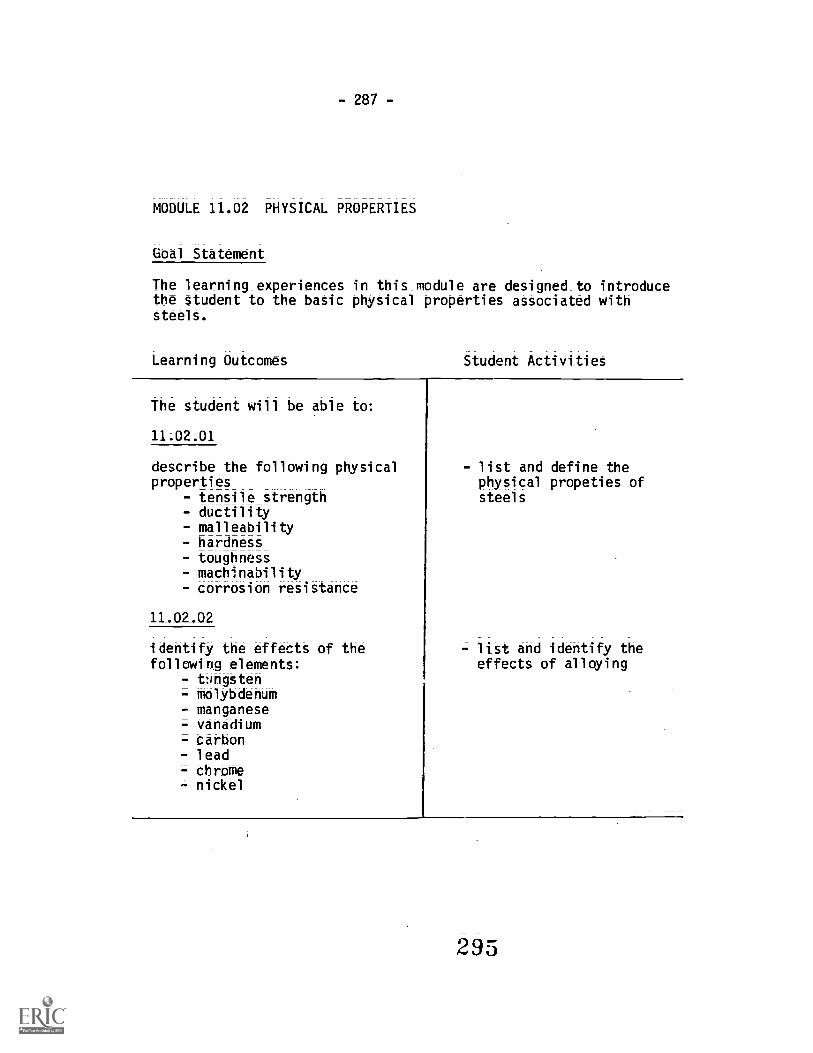
-287-
MODULE 11.02 PHYSICAL PROPERTIES
Goal Statement
The learning experiences in this module are designed to introducethe student to the basic physical properties associated withsteels.
Learning Outcomes Student Activities
The student will be able
11.02.01
describe the following physicalproperties
- tensile strength- ductility- malleability- hardness- toughness- machinability- corrosion resistance
11_.02_.02
identify the effects of thefollowing elements:
- t:Ingsten- molybdenum- manganese- vanadium- carbon= lead- chrome- nickel
- list and define thephysical propeties ofsteels
list and identify theeffects of alloying

-288-
MODULE 11.03 HEAT TREATMENT
Goal Statements
The learning experiences in this module are designed to:
a. introduce the student to the various heat treating operations,and
b. enable the student to describe the purpose of the heat treatingoperations.
Learning Outcomes Student Activities
The student will be able to:
11.02.01
recognize the purpose and methodsof stress relieving
11.03.02
recognize the method and purposeof a full annealing operation
recognize and understand the stepsrequired to perform a hardeningoperation
= heating- soaking= cooling
11.03.04
recognize the various methods ofsurface hardening
- cyaniding- carburizing- nitriding- flame hardening- induction hardening
- identify and describe themethods of and purposesfor stress relieving
- identify and describe themethods of and purposesfor a full anneal
- perform an annealingoperation on a samplepiece
- identify and describe thehardening process
- perform a hardeningoperation on a samplepiece
- identify and describe thepurposes of and methodsused for surface hardening
1296

Section FourResource Materials
CAREERCAREERCAREERCAREERCAREERCAREERCAREER.CAREERCAREn3CAREERCAREERCAREERCAREERCAREERCAREER
PREPARATION PROGRAMPREPARATION PROGRAMPREPARATION PROGRAMPREPARATION PROGRAMPREPARATION PROGRAMPREPARATION PROGRAMPREO_ARATIOR PROGRAMPREPARATION PROGRAMPREPARATION PROGRAMPREPARATION P_ROGRAPREPARATION PROGRA_ -
PREPARATION PROORA.__.PREPARATION PROGRA._PREPARATION PRQGRA_PREPARATION PROGR14...

- 291 -
RESOURCE MATERIAL
METAL FABRICATION
GRADE 11 AND 12 WELDING
1. Welding (1975) Publications Services Branch, 878 ViewfieldRoad, Victoria, B.C. V9A 4V1. Order numbers are:
MN0037 Section 1 IntroductionMN0038 Section 2 SafetyMN0039 Section 3 Trade ToolsMN0040 Section 4 Joint DesignMN0041 Section 5 Distortion ControlMN0042 Section 6 Oxy-Acetylene (Welding Equipment,
Processes and Applications)MN0043 Section 7 Flame CuttingMN0044 Section 8 Arc Welding (Equipment, Processes
and Applications)MN0045 Section 9 Identification of MetalsMN0046 Section 10 Codes, Specifications, StandardsMN0047 Section 11 Destructive and Non-destructive Testing
and SymbolsMN0048 Section 12 Welding SymbolsMN0049 Section 13 Iron and SteelMN0050 Section 14 Aluminum and Aluminum AlloysMN0051 Section 15 Stainless SteelMN0052 Section 16 Alloys and Die CastingsMN0053 Section 17 Glossary of Commonly Used TermsMN0054 Section 18 Aluminum Welding Manual
2. Tungsten_Inert_Gas_Weldlng (1960Z) Publication ServicesBranch, 878 Viewfield Road, Victoria, B.C. V9A 4V1.Order Number: MN0005
3. Metal Inert Gas Welding (1960Z) Publication Services Branch,878 Viewfield Drive, Victoria, B.C. V9A 4V1Order Number: MN0004
4. Gas Metal Arc Welding (1972) Publication Services Branch,878 Viewfield Road, Victoria, B.C. V9A 4V1. Order Number:MN0032
5. Blue Print Reading_for Welders Bennett A.E., Louis andSly, Delmar Publishers, Albany, New York 12205
298

- 292 -
6. Modern Welding Althouse; Turnquist, Bowditch The
Goodheart=Willcox Company Inc., South Holland, Illinois
ISBN 0=87006-210-7
7. New Lessons in Arc Welding Lincoln Electric Company of
Canada Ltd. Leaside, Toronto 17, Ontario
Pocket Welding Gulde Acetogen Welding Supplies Ltd.,
1339 Franklin Street, Vancouver, B.C. V5L 1PZ
9. Rigging Manual D.E. Dickie, P.Eng., ConStruction Safety
Association of Ontario, 74 Victoria Street, Toronto, Ontario
M5C IA5
Resources 10-18 available from: Union Carbide, Ste. 280 - 10991
Shellbridge Way, Richmond, B.C. V6X 3C6
10. The Oxy-Acetylene Handbook Union Carbide Part #781F00 (soft
cover) Part #787F00 (hard covered text)
11. The Properties, Selection-and Applications of Welding Gases
Union Carbide Part #800C28
12. Plain Talk About Fuel_Gases Union Carbide Part #800053
13. Oxy-Acetylene Welding of Steel Pipe Union Carbide
Part #639119
14. Welding Power Handbook Union Carbide Part #674401
15. MIG Welding Handbook Union Carbide Part #791F18
16. How to do High Quality -Short Arc Welding of Pipe Union
Carbide Part #791F18
17. Basic Oxy-AcetyleneWelding - Cutting and Heating Practices
Union Carbide Part #791F20
18. Sub Arc Welding -Handbook Union Carbide Part #791F28
19. Welding_, Cutting_and_Heating Guide Victor Equipment Company
of Canada Ltd., 1140-A Brookdale Street, Cornwall, Ontario
20. Welding Pender, James A. McGraw-Hill Ryerson Ltd., Toronto
Ontario ISBN #07082576-9
21. Welding Processes Griffin, Ivan H.& Rode, Edwin Delmar
Publishers, Mountainview Avenue, Albany, N.Y. 12205
2j

=293-
SAFETY
22. Ws__Smart to be Safe: Canadian Liquid Air, 8390 Manitoba,
Vancouver, B.C. V5g-3A7
23. fode for Safet in Electric and Gass-Weidin and Cuttin
ations Canadian Standards £ssaciation, 178 Rexdale
Blvd., Rexdale, Ontario M2J 4G8 C.S.A. W117
24. Head- and Eve Protection Canadian_ Standards Association,
178 Rexdale Blvd., Rexdale, Ontario M2J 4G8 C.S.A. Z94
25. Safe Practices for Installation-and-Operation_of Am:AcetylenP Welding and Cutting Equipment Compressed Gas
Assoication, 500 Fifth Avenue, New York; N.Y. 10110
26. Safe-Handling of Compressed Gas Cylinders Compressed
Gas Association, 500 Fifth Avenue, New York, N.Y. 10110
27. Standard of the National Fire Protection Association for
Installation and Operation of Gas Systems_forWelding
and_Cutting National Fire Protection Association,Batterymarch Park, Quincy, Mass. 02269 NFPA 51B
28. Cutting and Welding Processes National Fire Protection
Association, Batterymarch Park, Quincy, Mass 02269
NFPA 51B
29. Standard for Fire Protection in Use-of-Cutting and Welding
Processes National Fire Protection Association, Batterymarch
Park; Quincy, Mass. 02269 NFPA 51B
30. Standard for the Installation and Operation of _Oxygen-Fuel
Gas_Systems for Welding and Cuttin National_fire Protection
Association, Batterymarch Par , Quincy; ass 02269 N P 51
31. Safety in Welding and Cutting American Welding Society,
2501 N.W. 7th Street, Miami, Florida 33125 AWS Z49.1
32. Recommended -Safe Practices for_Gas-Shielded Arc Welding
American Welding Society, 2501 N.W. 7th Street, Miami,
Florida 33125 AWS A6.1
33. Safe Practices for Weldin and_Cuttin Containers tnat
have held Combustibles American Welding Society, 2501
N.W. 7th Street, Miami, Florida 33125, AWS A6.0
3u0

34; SAFETY FILMS
-294-
Safety Doesn't Happen Safety for Welders How Fires
Start_in_Industry Your Richest Gift National IndustrialFilm Library, Canadian Film Institute,
35. Stainless Steel. What:it is and How to Weld it. Stoody
Company; Industry; California 91749
36; Registered Welders "C" Level Program Ministry of Education,Post-Secondary Resource Centre, 7451 Elmbridge Way, Richmond, B.C.
3ui

= 295Rigging and Erection
INTRODUCTION
The field Boilermaker relies upon a variety ofrifting and support mechanisms to transfer andsecure material and equipment on the jobsite. Atone extreme, immense, sophisticated cranesperform massive lifting and moving operationswhile at the other, simple systems of ropes andpulleys having sufficient mechanical advantagemanage smaller operations to enable "man-power" to provide the required energy. In bothcases, the fundamental unit of the system is theline or rope, and the Boilermaker must have acomplete understanding of the composition,characteristics, capabilities and uses of all typesof line and rope. This chapter describes naturalfibre, synthetic fibre and wire rope.
KNOTS AND HITCHES
Both natural and synthetic fibre lines can be tiedin various ways to produce knots andhitches to serve specific functions in riggingand erection operations.
In making knots and hitches, the rope (Figure 7-1) is described as having three parts:1. The running end or free end used when
making a knot or hitch.2: The standing part is the main line or inactive
length of rope.3. The bight is the part, usually a loop, between
the running end and the standing part.
SECURING LINE ENDS
When a rope is cut, the raw end(s) tends tounravel or untwist and should be secured to
Bight
StandingPart
Figure 7-1. Parts of the Rope
prevent losing functional cord. Knotting the rawend is simple, but whipping has several ad-vantages:
1. It does not significantly increase the rope'scircumference and thus will still threadthrough openings:It is a more durable and secure fastening:
. It can be applied before a rope is cut toprevent any untwisting.
WHIPPING A LINE END
Figure 7 -2 illustrates the steps involved in whip-ping a line end:
Step 1. Using a small cord, make a bight nearthe end and lay the doubled cordalong a groove in the rope betweentwo strands: The bight should projectabout 1/2. beyond the end of the rope.
Step 2. Begin wrapping the standing part ofthe cord tightly around the line andcord.
Step 3. Continue to wrap toward the end ofthe rope, ending about 1/2- from thecut. The wrapped portion should be aslong as the equivalent of 1-11/2 timesthe rope diameter:
Step 4. At the end of the wrap, slip the cordend through the bight. Then pull thefree end of the cord until the bight isdrawn under the whipping and thecord is tightened.
Step 5. Cut off ends at the edge of the wrap-ping leaving a finished termination.
KNOTS AT THE END OF A LINE
1. The overhand knot (Figure 7-3) is the sim-plest knot to make, but should be used onlywith small cord or twine on parcels. On alarger rope used in handlines and ropeblocks this knot jams when pulled tight anddamages the fibres of the rope.
2. The figure eight knot (Figure 7-4) does notinjure the rope fibres and is larger than anoverhand knot for tying on the end of a ropeto prevent it from slipping through a
302 fastening or a loop in another line.

= 296 =
Step 1
<4-
Step 2
Figure 7-2. Whipping a Line End
KNOTS FOR JOINING TWO LINES
1. The square or reef knot (Figure 7-5) is usedfor tying together two ropes of the same size,or for tying together the ends of a short ropeto make a temporary endless sling. Properlytied, a square knot will not slip when therope is dry and has 50% of the rope strength.
When tying a square knot, the standing ;)artand the running end of each rope must pas:
:411")
Step 4
Step 5
through the bight of the other rope in thesame direction. A square knot is easily un-tied by grasping the ends of the two bightsand pulling the knot apart.
. The granny knot or the thief knot (Figure 7-6) looks like a square knot, but will slip andjam under a load.A single sheet bend (sometimes called aweaver's knot) is used to tie together twodry ropes of unequal size. Figure 7=7

Rigging and Erection- 297 -
Figure 7-3. Overhand Knot
Figure 7-4. Figure Eight Knot
Figure 7-6. Granny Knot
illustrates the method of tying a single sheetbend. The knot will draw tight under lightloads but will loosen or slip when the linesare slackened.
4. A double sheet bend (Figure 7-8) is used tojoin wet or dry lines of equal or unequal size.It will not slip or draw tight under heavyloads.
First tie a single sheet bend (do not pull ittight), then take one extra turn around thebight, passing the running end under the
Figure 74. Tying a Square Knot 3 u 4

- 298
2
Figure 7-7. Tying a Single Sheet Bend
Figure 7-8. Double Sheet Bend
r-. rRr
if
4
Figure 7-9. Tying a Carrick Bend

299 -Rigging and Erection
Smaller line and over the larger line as forthe single short bend.
5. The Carrick bend is used for heavy loadsand for joining heavy line. It will not drawtight under a heavy load. Figure 7-9illustrates the steps in tying a carrick bend.
KNOTS FOR MAKING LOOPS
1. The bowline knot makes a non-slip loop thatwill not tighten under straining and can beuntied easily when the tope is slack. Figure
2
Figure 7-10. Tying a Bowline Knot
7-10 illustrates the steps in tying a bowlineknot.
2. The double bowline knot (or Frenchbowline) provides a secure, two-loop Slingthat can serve as a seat for an operator (bypassing a small, notched board through theloops) or as spreaders to sling a load. Figure7-11 illustrates the steps in tying a doublebowline.
3. The running bowline knot is the basic knotused in rigging for raising or lifting loads asit produces a choker type sling at the end o;
4
3u6

300 -
Figure 7-11. Tying a Double Bowline Knot
a single line. Figure 7-12 illustrates the stepsin tying a running bowline knot.
4. A bowline on the bight is tied to form adouble loop in the middle of a line that canbe used as a seat or as a spreader to sling aload. Figure 7-13 illustrates the steps in tyinga bowline on the bight.
5. A Spanish bowline forms two loops or "rab-bit ears" providing a double sling for liftinground objects or for rescue work. Figure 7-14illustrates the steps in tying a Spanishbowline.
6. The harness hitch produces a loop in a linewhich will not slip. Figure 7-15 illustrates thesteps in tying the harness hitch. 3u7
4
HITCHES
1. The half hitch is used to secure the freeend of a line to a timber or to another largerline. Figure 7-16 shows unsafe and safe halfhitches.Two half hitches (Figure 7-17) provide amore secure fastening to a pole or timber. Itis important that the second half hitch ismade by passing the running end aroundthe standing part and back under itselfagain as shown in Figure 7-17.
2. A round turn and two half hitches is analternative method of fastening a line to atimber or pole, and involves passing therunning end of the line in two complete

301 -Rigging and Erection
1
2
Figure 7-12. Tying a Running Bowline Knot
2
Figure 7-13. Tying a Bowline on the Bight
3 u 8

- 302
4
Figure 7-14. Tying a Spanish Bowline
turns around the pole before making thetwo half hitches as shown in Figure 7-18.
3 The clove hitch offers a fast, simple way offastening a line to a post; timber or pipeand can be tied at any point in the line. Totie a clove hitch in the middle of the line,make two turns close together in the lineand twist them to bring them back to backas shown in Figure 7-19. Slip the loops overthe post. To tie a clove hitch at the end ofthe line, two underhand loops are tiedaround the post as shown in Figure 7-20.
4. The rolling or Magnus hitch is used tofasten a line to another line, cable, timberor post and it will remain tight under ten-sion or pull. This_hitch is also known as themooring hitch. Figure 7-21 illuStrate8 thesteps in tying the rolling hitch.
5. A sheepshank is used to shorten a rope asa temporary measure. This may benecessary to take the load off a weak orb
5
damaged part of the line beforereplacement can be accomplished. Figure7-22 illustrates the steps in tying the sheep-shank.
6. The timber hitch is used to fasten rope tosteady loads of posts, planks, timbers andpipes. The knot will loosen when the ten-sion or pull is relieved. The hitch beginswith a half hitch and is completed by turn-ing or twisting the running end around it-self two or three times following the lay ofthe rope (Figure 7=23).
7. A timber hitch and half hitch provides amore secure hold on heavy poles or timbersfor lifting or hauling. This involves tyingone or two half hitches around the load,and further along tying a timber hitch withthe running end of the line (Figure 7-24).
8. A catspaw (Figure 7-25) is a particularlyuseful method of attaching the middle of a

303Rigging and Erection
2
3
Figure 7-15. Tying a Harness Hitch
'Ay
-) Safe "Figure 7-16. Safe and Unsafe Half Hitches
4
5
v... 4.ftel121
_
"""1 "
Unsafe
$;, ;
4' ,"-
3m t)

304
Figure 7-17. Two Half Hitches
Figure 7-18. Round Turn and Two Half Hitches
tic
Figure 7-19. Tying a Clove Hitch in theMiddle of a Line
line to a hook. When removed from thehook, it unties itself.
9. The fisherman's bend provides a securefastening for a tine or cable to an anchor orother situations where alternate tighteningand slackening in the line occurs. Figure 7--26 illustrates a fisherman's bend. With therunning end, take two turns through oraround the object to be fastened, thenaround the standing part and through theloop formed by the turns. Finally, make ahalf hitch around the standing part andseize the running end to the standing part.

- 305Rigging and Erection
Figure 7=20. Tying a Clove Hitch at the End of Line
Figure 7-21. Tying a Rolling Hitch
10. The scaffold hitch is used to support singleScaffold planks so they will-hang level andbe unable to tilt. Figure 7-27 illustrates thesteps in tying a Scaffold hitch.
11. The Speir knot provides a constant loopwith a non=Slipping knot and can bereleased easily by a pull on the runningend. Figure 7-28 illustrates the steps intying a Speir knot.
12. The becket hitch provides a secure meansof fastening a line to a ring such as thebecket of a block. Figure 7-29 illustrates
the steps in tying a becket hitch. Pass therunning end of the line through the eye ofthe ring, back around the standing part ofthe line, then over both sides of the loopand up through the bottom half of the loopas shown. Pull tight.
13. Barrel slings can be tied to hold barrelshorizontally or vertically. The horizontalsling (Figure 7-30) is made by tying abowline with a long loop. Make two "ears"by bringing the line at the bottom of theloop up over the sides of the loop and slide
312

- 306 -
2
Figure 7-22. Tying a Sheepshank
the "ears" over the ends of the barrel. Thevertical sling is made as illustrated inFigure 7-31.
Note: Rope strength is reduced to 50% when aknot or bend it tied anywhere along itslength.
Rope strength is reduced to 75% when ahitch is Pied anywhere aiong its length.
313
A1
Figure 7-23. Tying a Timber Hitch
Figure 7-24. Tying a Timber Hitch andHalf Hitch

=307=Rigging and Erection
Figure 7-25. Catspaw Hitch
2
Figure 7-26. Fisherman's Bend
314

= 308 ---
AI-
7
Figure 7-27. Tying a Scaffold Hitch
8
3J

Rigging and Erection309
3
5
Figure 7-28. Tying a Speir Knot
2
316

- 310
1
3
Figure 7-29. Tying a Becket Hitch
4
31-'
4.
;111.r,
'

Rigging and Erection - 311 -
Figure 7-30. Horizontal Barrel Sling
Figure 7-31. Making a Vertical Barrel Sling
SPLICES
Splicing is a process of joining two ropestogether, or joining the end of a rope to a pointon the standing part. Splicing reduces the ratedStrength of the rope by 10-15%. Both natural andsynthetic fibre ropes can be Spliced, but fOr alltypes of splices, two or more extra tucks arerequired for synthetic fibre rope. An importantconsideration in making splices is the care thatmust be taken in unlaying the rope andreweaving the strands so that the form and lay ofthe rope are not disrupted.
I
1 R
4 1-17
,71 assn

- 312 -
SHORT SPLICE
The Short Splice is the strongest type of splice;however, it has the disadvantage of increasingthe diameter of the rope to such an extent that itis unsuitable for some uses such as runningthrough blocks or sheaves.
Procedure
Step 1. Unlay the strands at end of each ropefor six or eight turns: Whip the ends ofthe strands to prevent their untwisting,and bring together so that each strandof one rope alternates with a strand ofthe other (Figure 7-32, Step
Step 2. Bring the ends tightly together andapply a temporary seizing where theyjoin (Figure 7-32, Step 2).
Step 3. Take any one strand and begintucking, the sequence being over oneand under one. Figure 7-32, Step 3,shows how Strand A is passed overthe strand nearest to it, which isStrand D, and then under the nextstrand. Strand E.
Step 4. Rotate the splice away from you one-third of a turn and make the secondtuck; Strand B is passed over Strand Eand then under Strand F (Figure 7-32,Step 4).
Step 5. Before making the third tuck, rotatethe splice again one-third of a turnaway from you. Strand C is thenpassed over Strand F, and under thenext one, Strand D. The splice now ap-pears as in Figure 7-32, Step 5.
Step 6. This completes the first round of tucksin the left hand half of the splice. Eachstrand should new be tucked at leasttwice more, always over one and un-der one as before, making sure thateach strand lies snug and is withoutkinks.
Step 7. To finish the splice, reverse the ropeend for end so that Strands D, E and Fare now at the left instead of the right(in the same position of Strands A, Band C in the illustrations) and repeatthe tucking operation on their side ofthe rope. Each of the six strands willnow have had at least three tucks. Atapered splice is made by taking. twomore tucks with each strand, cutting
away some of the threads from eachstrand before each extra tuck.
Step 8. When tucking is finished, remove thecentre seizing and cut off the ends ofall strands, leaving at least 3/4" oneach end. To give a smooth ap-pearance, roll the splice back andforth, either under your foot or bet-ween two boards. The completedShort Splice should lock somethinglike the illustration in Figure 7-32,Step 8.
Step 2
Step 4
Step 5
Step 8
wizlizgatEESIgZitzs=Figure 7-32. Making a Short Splice
31D

- 313 -Rigging and Erection
LONG SPLICE
The Long Splice is used for pulley work since itpermits ropes that have been spliced to be runthrough sheave blocks without jamming orchafing. Unlike the short splice, the diameter ofthe spliced rope is increased very slightly.
Procedure
Step 1. To make this splice, begin by unlayingone strand of each rope for 10 or 15turns, and whip the ends of eachstrand to prevent untwisCrig. Thenlock the two ropes together by alter-nating the strands from each end asillustrated in Figure 7-33, Step 1.
Step 2. Starting at one end, take an oppositepair of strands, A and B, and unlayStrand A. Follow it with Strand B, turnby turn, continuing until only 1' or lessof Strand B remains. Keep Strand Btight during this step and pull it downfirmly into Strand A's former place.Repeat this operation with Strands Cand D. Strand D is unlaid and Strand Cis laid in its place. The splice at thisstage is illustrated in Figure 7-33, Step2.
Step 3. Now each pair of strands is tiedloosely together with a simpleoverhand knot, as indicated byStrands A and B in Figure 7-33, Step 3.Each knot is then pulled down into therope like Strands C and D.
Step 4. Each strand is now tucked twice, overand under, as done in making theShort Splice. Figure 7-33, Step 4shows Strands C and D after tucking.If a smaller diameter splice is desired,tapering can be done by tucking eachstrand twice more, cutting away someof the threads for each additionaltuck.
Step 5. When tucking is finished, cut allstrands off close to the rope and rollthe splice on the floor under your footto smooth it out The completed LongSplice is illustrated in Figure 7-33,Step 5.
SIDE SPLICE
The Side Splice is also called the Eye Splicebecause it is used to form an eye or loop in theend of a rope by splicing the end back into its
Step 2
Step 3
Step 5
AilaiS0aSigNagiSilaFigure 7-33. Making a Long Splice
own side. This splice is made like the ShortSplice except that only one rope is used.
Procedure
Step 1. Start by seizing the working end of therope. Unlay Strands A, B and C, to theseizing and whip the end of eachstrand. Then twist the rope slightly toopen up Strands D, E and F of thestanding part of the rope, as indicatedin Figure 7=34, Step 1.
Step 2. The first tuck is shown in Figure 7-34;3 Otep 2. The middle strand is always

314
tucked first, so Strand B is tucked un-der Strand E; the middle strand of thestanding part.
Step 3. The second tuck is now made asillustrated in Figure 7-34, Step 3. LeftStrand A of the working end is tuckedunder Strand D, passing over StrandE.
Step 4. Figure 7=34, Step 4 illustrates how thethird tuck is made. To make Strand Feasy to get at, the rope is turned over:Strand C now appears on the left side:
Step 5. Strand Cis then passed to the right ofand tucked under Strand F, asillustrated in Figure 7-34, Step 5. Thiscompletes the first round of tucks.
Step 6. Figure 7-34, Step 6 illustrates thesecond round of tucks started, withthe rope reversed again for ease inhandling. Strand B is passed overStrand D and tucked under the nextStrand to the left. Continue withStrands A and C, tucking over onestrand and then under one to the left:To complete the splice; tuck eachstrand once more.
Step 7. Remove the temporary seizing and cutoff the strand ends, leaving at least1/2" on each end. Roll the splice backand forth under your foot to even upand smooth out the strands. The com-pleted Eye Splice is illustrated inFigure 7-34, Step 7.
NATURAL FIBRE LINE
MANUFACTURE OF NATURAL FIBRE LINE
Natural fibre line is constructed by a process oftwisting vegetable fibres together. Individualfibres are grouped and twisted to form yarns,and yarns are grouped and twisted together toform strands (Figure 7 -35). Finally, a number ofstrands are twisted to form a line. The line twistis balanced by reversing the direction of twist foreach set of components: fibres and strands aretwisted opposite to yarns.
TYPES OF NATURAL FIBRE LINE
Fibre line is classified on the basis of the kind ofvegetable fibres used to manufacture it;
Step 1 Step 2
Step 3 Step 4
Step 5 Step 7
Step 6
r?, 7-34. Making a Side Splice

= 315Rigging and Erection
A
Figure 7-35. Cons "suction of Natural Fibre Line
Manila fibres are made from plantain leaVes.Superior quality manila line is_ made from longfibres of light colour, as it is softer, more elastic,
. stronger, durable and water resistant. Itssmoothness makes it preferable for running overblocks and sheaves.
Sisal line has a harsher feel than manila and isabout 80% as strong. It has the advantage oftolerating exposure to sea water very well.
Hemp fibreS are short and soft, but it produces astrong, rough line. Tar soaking, althoughreducing the line's strength and flexibility, isnecessary to reduce deterioration from damp-ness.
Coir and Cotton Coir line is rough and elasticand floats on water. It is only 25% as strong ashemp. Cotton can tolerate a great deal of ben-ding and running, but is too light for most uses.
Forms of Natural Fibre Line
The arrangement of strands in a line is an im-portant feature of its construction. The threeprincipal forms are: hawser laid, shroud laid andcable laid line:
Hawser laid line is composed of three strands ina right hand lay (Figure 7-36).
Shroud laid line is composed of four strands in aright hand lay around a centre core (Figure 7-36):
Cable laid line is composed of thee lines (righthand Hawser) arranged in a left hand lay (Figure7-36).
Houser Laid Line
Shroud Laid Line
Cable Laid Line
Figure 7-36. Forms of Natural Fibre Line
CHARACTERISTICS OF NATURAL FIBRE LINE
Size Fibre line is designated by diameterand circumference (in inches).
Weight The number of feet per pound of linecan be estimated with the following formulawithin 12% accuracy:
(d i a me ter)2
Example: for 5/8 inch line
3.4(5/8)2
= 8.7 feet per pound
Strength Line strength is described in termsof: 1) breaking strength and 2) safe workingcapacity. The breaking strength divided by thefactor of safety gives the safe working capacitywhich should never be exceeded; Excess loadsdamage the fibres and reduce the strength andlife of the line. The condition of the line, in termsof exposure, waar, use and °ending, must beconsidered in estimating its strength as thesetett-ors over time will greatly reduce the line'scapability.

316
Rated capacities for safe loads are listed intables for new line only. (See, for example, Table7-1.)
A rule of thumb for estimating the safe workingcapacity (in tons) of manila line is to square thediameter (in inches), for example, a 11/8" manilaline would have a safe working capacity of117/64, or approximately 1'/4 tons.
CARE AND MAINTENANCE OF NATURALFIBRE LINE
The functional life of natural fibre line can be ex-tended with proper care in handling and main-tenance. Knowledge of the characteristics andlimitations of each kind of line will provideguidelines for good handling practices.
Inspect lines frequently to determine the ac-tual condition of the inner fibres, which is notevident on the surface. Grasping the line firmlywith two hands, untwist it slightly to expose theinner portion, and look for the following:1. Mildew - inner fibreS are dark and stained
and have a musty odour2. Broken Strandt or yarns
. Chafing residue - dirt and sawdust-likematerial inside the line
4. Fragmentation of the core - core breaksaway in small pieces, indicating overstrain.
Examine the line in this way in a number ofplaces and finally pull out and stretch a few ran-dom fibres to test for breakage resistance. Anyline found to be deficient should be destroyed orcut into pieces too short for hoisting.
Protection of Line Ends Raw or cut ends ofline should be secured to prevent unlaying.Tying a knot at the end of a line, or whipping willsecure the lay.
Storage Deterioration of natural fibre linecan be prevented by good storage practices.These include the following conditions:1. Storage areas should be dry.2. Lines should be dried before storing.3. Circulation of air around coiled line should
be provided such as gratings to support thecoils.
4. Fibre line should not be covered unless ab-solutely required.
TABLE 7-1. PROPERTIES OF MANILA AND SISAL LINE
Nominaldiameter
Circum-ference
Weightper 100'
No. 1 Manila Sisal
(inches) (inches) (pounds) Breaking Safe Load Breaking Safe LoadStrength (pounds) Strength (pounds)(pounds) F.S. .4 (pounds) F.S. .4
1/4 3/4 1.71 550 150 440 120
2/3 1 1/8 3.45 1,275 325 1,020 260
1/2 1 1/2 7.36 2,650 660 2,120 520
3/5 2 13.1 4,400 1,100 3,520 880
3/4 .. ...... 2 1/4 16.4 5,400 1,350 4,320 1,080
7/8 2 2/4 22 0 7,700 1,920 6,160 1,540
1 3 26.5 9,000 2,250 7,200 1,800
1 1/8 3 1/2 35.2 12,000 3,000 9,600 2,400
1 1/4 3 3/4 40.8 13,500 3,380 10,800 2,700
1 1/2 4 1/2 58.8 13,500 4,620 14,800 3,700
1 3/4 5 1/2 87.7 26,500 6,625 21,200 5,300
2 6 105.0 31,000 7,750 24,800 6,200
2 1/2 7 1/2 163.0 46,500 11,620 37,200 9,300
3 9 , 237.0 64,000 16,000 51,200 12,800
NOTE: Breaking strength and safe loads given are for new line used under favorable conditions. As line ages ordeteriorates, progressively reduce safe loads to onehalf of values given.
I
23

Rigging_ and Erection317
Prevention of Moisture Damage Since fibreline will contract when wet, it should beslackened before exposure to rain or dampness.
Prevention of Damage to Strands Althoughcontinued use will result in some fibre damage,this can be minimized by:1. Washing line that is muddy or sandy2. Using softeners to pad sharp corners over
which the line must be pulled3. Keeping line out of sand and dirt as much as
possible
4. Using knots that are easy to untie5. Repairing broken strands in the line as soon
as possible.
Coiling and Uncoiling New natural fibre lineis delivered in coils of 800'=1200' and lashedor bound. Generally an instruction tag will ac-company the coil. After cutting the bindings orlashings, grasp the line end inside the coil at thebottom and pull it up through the middle toprevent kinks from forming (Figure 7-37).
Starting End
kkk
Figure 7-37. Uncoiling a Coil of Fibre Line
SYNTHETIC FIBRE ROPE
CHARACTERISTICS OF SYNTHETIC FIBREROPE
Synthetic fibre ropes, particularly nylon andpolypropylene, are becoming more widely used,replacing manila rope in many instances. Theseropes have individual fibres running the entire
length of the line rather than snort, overlappingfibres as in natural fibre rope. This accounts forthe greater strength of synthetic fibre line (SeeTable 7-2).
TABLE 7-2. RELATIVE STRENGTH OF FIBREROPES (DRY)
Type of Rope Relative Capacity(Related to Nylon)
Nylon
Polyester
PolypropylenePolyethylene
Manila
100%
94%
81%
73%
67%
Synthetic fibre ropes are generally impervious torot, mildew and fungus and have goodresistance to chemicals. They are lighter andeasier to handle, and have excellent impact,fatigue and wear resistance, outwearing manilaropes by four or five times. They are liable tomelt at high temperatures, however, and shouldnot be used where heat is excessive or friction ishigh enough to melt the fibres. They should notbe used near welding operations. Generally, syn-thetic fibre rope is abrasion resistant and cantolerate long exposure to water without anynoticeable loss of strength or change in ap-pearance.
TYPES OF SYNTHETIC FIBRE ROPES USEDIN RIGGING
Nylon Rope Nylon rope is two and one halftimes stronger than manila and is the mostwidely used of the synthetic rope family. It ischalky white in colour, has a smooth surface, issoft and pliant and has a feeling of elasticity.
Some properties of nylon ropes are:1. High breaking strength (wet or dry)2. Light weight per unit of strength3. Excellent elasticity and tensile recovery4. Superior absorption of impact and shock
loads
5. Excellent flex and abrasion resistance6. Good flexibility7. Excellent resistance to rot8. Good sunlight and weather resistance9. High melting point.
324

318
Due to its continuous fibre construction, nylonrope is strong and resistant to creep undersustained load. Its elasticity recommends its usewhere high energy absorption is needed orwhere shock loading is a factor. The highdegree of stretch can be a serous disadvantageif headroom for lifting is restricted and slingsmust be as short as possible. Under actual ser-vice conditions, nylon rope will stretch to about16% under working loads and over 40% underbreaking loads. The initial loading of a nylonrope produces a permanent elongation of ap-proximately 6%. but recovery is complete fromsubsequent stretching under load. Therefore;nylon ropes should be broken in prior to fielduse.
Nylon rope tolerates heat without loss ofstrength or physical properties up to "*.0°F
(melting point 482'F.). Nylon ropes absorbmoisture and lose approximately 10% of theirstrength when wet as well as becoming veryslippery. Full recovery occurs when the rope
dries out. Table 7-3 compares nylon and manilaropes under a heavy sustained load.
Store nylon rope away from heat and exposureto sunlight. Nylon is highly resistant to alkalies,but can be degraded by most acids, paints andlinseed oil, and all contact with chemicalsshould be avoided. If contact is suspected, washthe rope thoroughly in cold water and thencarefully examine the fibres for evidence ofweakening.
Braided Nylon Rope Braided nylon ropeprovides the highest possible strength since theload is divided eqLialiy between a braided sheathand a braided core The rope is soft and flexibleand does not twist or kink. Twisted three strandrope transmits a turning, twisting motion underload while braided nylon does not.
Braided nylon presents approximately 50% moresurface area for wear and grip, is stronger forsize and more stable, exhibits less stretch when
TABLE 7-3. COMPARISON OF NYLON AND MANILA ROPES UNDER HEAVY SUSTAINED LOAD
3.5 HOURS
Pi= 50% OF THE BREAKING LOAD OF THE NYLON ROPE
P2 .50% OF THE BREAKING LOAD OF THE MANILA ROPE
REASON
NYLON THREADS ARE CONTINUOUS
P--b
P2
FIBRES IN MANILA ROPE ARE NOT CONTINUOUS & TEND TOSLIP WHILE UNDER
LOAD.
25

- 319 -Rigging and Erection
working, has less permanent stretch and greaterflexibility than three strand nylon ropes.
The braided sheath and core construction isavailable in synthetic combinations in additionto nylon:1. Nylon core/nylon cover high strength,
more stretch, good wearing qualities2. Polypropylene core/nylon cover lower
strength, lower stretch3 Polypropylene core/polyester cover very
low stretch, high strength and good abrasionresistance.
For example, a nylon core/nylon cover rope witha nominal diameter of 7/8 inch carries a safeworking load of 4.800 pounds, while apolypropylene core/nylon cover rope will carry asafe working load of 4,150 pounds. Apolypropylene core/polyester cover rope willsupport a safe working load of 3,800 pounds.The safety factor for braided synthetic com-binations is 5.
Polyester Rope Polyester rope (Tradenames: Dacron, Terylene) is nearly identical tonylon in appearance but has little or no elasticfeeling. Size for size, it is heavier and not asstrong as nylon rope, although similar in con-struction. This is a continuous filament rope andresists creep under sustained loads. The lowstretch properties of polyester rope represent aconsiderable advantage where headroom islimited since, after the initial permanent stretchof approximately 6%; subsequent loads producea temporary lengthening of approximately 5.9%(compared to 16% for nylon). Polyester ropesshould be broken in before field use.
Abrasion resistance is similar to nylon rope. Likenylon, polyester rope is unaffected by tem-peratures up to 300°F. It absorbs much lesswater than nylon and thus does not lose strengthwhen wet. Polyester rope resists sun andweather damage as well as attack by rot andmildew, however, precautionary storage prac-tices are recommended. Polyester is moreresistant to chemicals than nylon, but exposureand contact should be avoided. Slings should bewashed frequently in cold water.
Polypropylene Ron° Polypropylene andpolyester ropes are almost identical in ap-pearance; they are available in various coloursand are smooth and pliant and Somewhat Slip-pery, particularly polypropylene.
A singular advantage of polypropylene rope isits ability to float on water; however, it is not asstrong as nylon or polyester and ranks betweennatural fibre ropes and the more sophisticatednylon and polyester.
Stretch properties of polypropylene ropes varywith the type of construction; however, theygenerally exceed those of polyester. Energy ab-sorption is approximately half that of nylon.
Polypropylene ropes have a heat toleratingcapacity comparable to nylon and polyester;however, some deterioration occurs in sunlight.Chemical resistance is generally good as isresistance to rot and mildew. An importantfeature is polypropylene rope's safety aroundelectricity as it is a non-conductor because it ab-sorbs no water.
Polyethylene Rope Polyethylene ropes arelow in strength compared with the other syn-thetic fibre ropes. They tolerate heat only up to250°F and undergo some deterioration insunlight. They are, however, resistant tochemicals except sulphuric acid.
WIRE ROPE
CHARACTERISTICS OF WIRE ROPEWire rope is used for so many purposes todaythat it is not practical to enumerate them all.Because of this widespread use it cannot be ex-pected that one type or construction of rope,varying only in size and strength, will meet allrequirements.
Listed below are some common terms and theirabbreviations used to designate types of con-struction of wire rope:
R.L.
L.L.
F.C.
I.W.R.C.
6-19
6-24
6-37
M.S.
C.C.
I.P.
S.I.P.
Gal
Regular LayLang LayFibre CoreIndependent Wire Rope Core6 strands 19 threads6 strands 24 threads6 strands 37 threadsMild SteelCast CrucibleImproved PlowSpecial Improved PlowGlv3nized
26
- 320 -
To determine the breaking strengths and safeworking loads for the various types of wire ropeused in the Boilermaking trade it is essential toknow the construction of the rope. The mostcommonly used wire rope is 6-19 and 6-24 PlowSteel in Ordinary Lay. Galvanized wire rope isused under certain unusual environmental con=ditions such as near salt water or chemicalplants and pulp mills. Lang Lay wire rope ismostly used on shovels and drag lines. Under ordinary conditions Fibre Core is used, but whereadditional strength or resistance to compressionis required Independent Wire Rope Core ischosen.
A process called Preforming of wire rope per-manently shapes the fibres into the position theywill occupy in the finished rope. This makes therope more stable and more resistant to un-stranding by reducing internal stresses:
GRADES OF WIRE ROPE
Grade 120/130 Special Improved Plow Type II isused in the manufacture of wire ropes forspecial installations where maximum ropestrength is required and conditions permit use ofthis heavy grade rope with existing hoistingequipment.
Grade 115/125 Special Improved Plow Type I isalso used for special applications whenbreaking strengths in excess of those obtainedwith Grade 110/120 are required and existingequipment can handle the rope size.
Grade 110/120 Improved Plow has high tensilestrength, tough wearing qualities and fatigueresistant properties. This is the most frequentlyused wire rope.
Three further grades of wire rope are in lessfrequent use. Their capabilitiet make themsuitable only in situations where strength issecondary to fatigue resistance. These gradesare: Grade 100/110 Plow, Grade 90/100 MildPlow and Grade 80/90 Cast Crucible.
Galvanized wires are coated with zinc atfinished size either by the "hot dip" or "electro"process.
Drawn Galvanized wires (sometimes calledDrawn After Galvanized or DAG) are coated withzinc at an intermediate size and the zinc-coatedwire cold-drawn to the final or required finishedsize.
Bryanized wire is zinc coated by a specialprocess employed by British company,whereby the zinc becomes nn integral part of theWire itself. Note that galvanized finishes can beapplied to any grade of rope wire exceptphosphor bronze and copper wires:
Corrosion Resisting wire is usually a chromium-nickel steel alloy with high resistance tocorrosion. It is used under conditions wheregalvanized wire will rust and fail.
Phosphor Bronze and Copper wires are usedonly where corrosion resistance and non-sparking qualities are required as in marine andhazardous industrial applications
WIRE ROPE LAYS
Regular Lay (Ordinary Lay) ropes have thewires in the strands laid in one direction whilethe strands in the rope are laid in the oppositedirection. This results in the wire crowns run-ning approximately parallel to the longitudinalaxis of the rope. These ropes resist kinking andtwisting and can withstand considerablecrushing and distortion due to the short lengthof exposed wires.
Lana Lay ropes have the wires in the strandsand the strands in the ropes laid in the samedirection. Thus the outer wires run diagonallyacross the rope and are exposed for longerlength than in Regular Lay ropes, providinggreater wearing surface and greater resistanceto abrasion. Lang Lay ropes are more flexiblethan Regular Lay and resist fatigue better: LangLay ropes are more liable to kink and untwistand will not tolerate the same degree of distor-tion and crushing. The ends of Lang Lay Ropesshould be permanently fastened to prevent un-twisting.
Right Lay or Left Lay ropes have strands"rotating" to the right, while a Left Lay rope isthe opposite. Most ropes in use are Right Layropes. (See Figure 7-38).
Preformed wire rope is constructed of strandsand fibres shaped permanently into the contourthey will take up in the completed rope. In Non-Preformed rope the wires are forcibly held inposition throughout the life of the rope, as canbe seen by cutting such a rope at any point,when strands and wires will immediately flyapart. Preforming the wires and strandspreleats this as they all lie naturally in their true
1.1 *kw 7

- 321Rigging and Erection
Lift lay LANG LAY
Ltit La9 REGULAR LAY
Figure 7-3g. Types of Wire Rope Lays
position; free from internal stress. The ad-vantages of Preformed wire rope are:1. It is flexible and Wilber and eagy to handle.
2. It runs smoothhl and evenly over Sheaves.3. It makes Lang Lay construction practical for
many applications. ?reformed rope in LangLay or Regular Lay is completely inert.
4. It gives considerably longer life thanRegular Lay rope of equivalent size due toreduction and uniform distribution of internal stresses.
It is the only wire rope that evenly balancesthe load on indiVidual strands and wires. Theload distribution on the single wires isremarkably uniform.It is safer to use as broken wires do notWicker out to tear at hands and clothing.It is more easily spliced, since there is noneed to seize the strands as :hey fall intocorrect position more easily:It resists kinking better than other ropes.It tolerates many of the abuses to which wirerope is often unavoidably subjected.
TYPES OF WIRE ROPE
Round Strand ropes are the simplest of the truerope types and are almost universal in their use:They consist of from 3 to 36 strands laid invarious arrangements concentrically around acore. The use.of round wires laid in geometricpatterns results in a round strand. Figures 7-39illustrates only two of many round strand wirearrangements available.
Where strands are made up of two or morelayers of wires around a centre wire the wires inthese layers may bc cross-laid. That is the pitchor length of lay will be longer for the outer
Right La9 LANG LAY
Right Lay REGULAR LAY
6 x 7 Round Strand 18 x 7 Round Strand
Fibre Core Fibre Core
Figure 7=39. Round Strand Rope
layers as related to the next inner layer. Thisconstruction is limited to small ropes and cords,to some ship ropes and to standing ropes inlarger sizes.
For all other purposes ropes of equal-laid con-struction are preferable. By this method alllayers of wires have the same pitch or length oflay. Each wire in each layer therefore lies eitherin a bed formed by the valleys between the wiresof an underlayer or alternatively along thecrown of an underlying wire. Because no layerof wires ever crosses over another an equal-laidrope maintains its diameter in service, has moresolid cross section and improved fatigue life ascompared to cross-laid ropes.
Flattened Strand ropes are built up of triangularshaped strands or strands of oval shape. Certaintypes. specifically non-rotating ropes. are builtof a combination of oval around triangular, orsometimes oval around round. In the case oftriangular shaped strands the wires forming thestrand are laid on a triangular shaped coreformed of a single triangular shaped wire or ofthree or more round wires. The wires forming anoval strand are laid on an oval shaped centreribbon or around a group of usually four roundwires laid parallel. Because of the triangularshape of the strands. flattened strand ropes
328

- 322 -
have smaller fibre cores than do round strandropes. Hence, size for size, flattened strandropes have approximately 10% greater metallicarea with comparable increased breakingstrength. Figure 7-40 illustrates two of thevarious flattened strand wire arrangementsavailable.
6x 7/.1 6x9/6x7Flattened Strand Flattened Strand
Fibre Core Fibre ..:ore
Figure 7-40. Flattened Strand Rope
With ropes of this type frictional wear is spreadover a greater number of outer wires of the ropeas compared with a round strand rope. In theflattened strand construction, with the frictiondistributed over a greater external surface, wearis more even and the loss of sectional area ofthe vital outside wires much reduced. Becauseof the smooth surface and circular cross sectionobtained with flattened strand rope the wear onsheaves and pulleys is materially reduced and inthe case of ropes used for endless haulagesystems the increased external bearing surfaceenables grips and clips to be more secureI em-ployed. Also, owing to its more solid con-struction, this type of rope is less likely to beforced out of shape by such clips.
Locked Coil rope differs completely from bothround strand and flattened strand rope! InsWadof a group of individual strands CtOSE d around acentral core member it is a single strand built upof layer upon layer of wires. The centre or coreof the locked coil rope consists of t concentriclaid strand of round wires. Around this core arelaid one or more layers of shaped wires, theouter layer always being interlecking. Theshape or shapes of all shaped wires in a lockedcoil rope depend on the rope diameter and itsend use Typical locked coil wire arrangementsare illustrated in Figures 7-41.
Locked coil ropes have a higher breakingstrength than stranded ropes for equal diameterand the same nominal strength grade. Becauseof their smooth external surface depreciation in
Locked Coil Locked CoilTrack Rope Winding Rope
Figure 7-41. Locked Coil Rope
strength caused by frictional wear on drums orpulleys is greatly reduced. Because of theirdesign locked coil ropes are less subject torotation and stretch than stranded ropes.
Concentric Strand rope as its name implies con-sists of round wires laid layer upon layer arounda centre wire. This simple strand construction isused exclusively for static purposes such asbridge suspension ropes, standing rigging andsimilar purposes. (See Figure 7-42).
Two general arrangements of wires are used.The first consists of concentric layers of wires ofone size around a somewhat larger centre wire.The second consists of one or more concentriclayers of wires of one size around a core groupmade up of an equal laid strand.
19 Wire 67 WireConcentric Strand Concentric Strand
Figure 742. Concentric Strand Rope
WIRE ROPE CORES
The core forms the heart of the rope and is tnecomponent about which the main rope strandsare laid. The core supports the strands and is in-tended to keep them from jamming against orcontacting each other under normal loads andflexings. The core may take one of several formsdepending on the conditions under which therope will be used
Fibre Core (Figure 7-43) is adequate for manytypes of service providing maximum flexibilityand elasticity to the wire rope. Generally madeof hard fibres, usually sisal and occasionallymanila, it may also be manufactured from man-

- 323 -Rigging and Erection
Figure 7-43. Fibre Core
made fibres such as polypropylene or nylon.These latter cores are useful where conditionssurrounding the rope's use could result inpremature failure of vegetable fibre cores. Sisaland manila fibre cores are impregnated duringthe cordage process with a suitable lubricanthaving preservative properties. Cotton and jutefibres are frequently used in cores for smallcords such as sash cords, etc.
Independent Wire Rope Core (IWRC) (Figure 7-44) consists of a 6 x 7 stranded steel wire ropewith a 7 wire centre strand. Its greatest use iswhere ropes are subjected to severe pressurewhile running over sheaves or winding on todrums. This core should be used when ropeoperates in temperatures damaging to natural orman-made fibres. It provides additional strengthand less stretch with less resilience.
Figure 7-44. Independent Wire Rope Core
Strand Core (Figure 7-45) consists of a strand ofsteel wires, nominally 7, 19 or 37. It is oc-casionally used in running rope of smallerdiameters rather than IWRC. It may also be usedin standing ropes, guys, suspender ropes, etc.where extra strength reduced stretch andmaximum resistance to weathering are required.
Armoured Core (Figure 7-46) is made of a layerof steel wires laid around a fibre centre. It
Figure 7-45. Steel Strand Core
Figure 7-46. Armoured Core
provides superior wire-to-wire contact with themain rope strands as compared to IWRC's. Thearmoured core provides greater strength andresistance to crushing than fibre core.
WIRE ROPE CLASSIFICATIONS
6 x 19 Classification This classificationcovers ropes with 6 strands closed around afibre or steel core and includes ropes having 17to 26 wires per strand; an example is shown inFigure 747. Rope of 6 x 19 classification is usedon a greater variety Of applications than anyother. Such ropes will be found on bridgecranes and gantrys, shop cranes and mobilecranes, hoists and derricks, dredges and clamshells, drag lines and scrapers, power shovelsand trench hoes, blastTholes drills and in in-dustry generally.
Ropes in this class are available in regular layor lang lay, with fibre core or with independentwire rope core. While usually right lay, left lay ismade for special purposes as, for instance,blast-hole drilling: The use of lang lay rope,where possible, also impi.oves flexibility; andprovides additional resistance to abrasive wear:
A wide choice of wire arrangements in thestrands is available, giving varying com-binations of flexibility and resistance to abrasivewear. This adaptability is primarily achievedthrough the number of outer wires in eachStrand, ranging from 8 to 12.
The diameter of wire rope is the main factor inthe size of load that the rope can safely take.Table 7-4 gives the breaking strains and safeworking loads for 6 x 19 plowsteel F.C. wirerope.
Figure 747. 6 x 26 Right Regular Lay,Fibre Core

- 324
TABLE 7-4. BREAKING STRAINS AND SAFEWORKING LOADS
6 x 19 Plowsteel F.C. Wire Rope
Diameter Breaking S.W.L,
Strain in Tons Tons
3/8 6.0 1.1
1/2 10.7 2.4
5[8 16.5 3.3
3/4 23.8 4.7
7/8 32.0 6.2
1 41.7 8.3
1.1/8 53.0 10.b
1.1/4 65.5 13.2
1.1/2 96.0 19.1
2 169.0 53.8
6 x 37 Classification This classificationcovers ropes with 6 strands closed around afibre or steel core and includes ropes having 27to 49 wires per strand: This rope is designed formaximum flexibility with a reasonable degree ofresistance to crushing and is in general use onapplications such as overhead shop craneswhere high rope speeds and multiple reevingare encountered and where layer-on-layer win7ding is normally involved. Such ropes also findwide-spread use in their larger sizes on powershoveis: dredges, drag lines, etc. where, for con=siderations of mobility and weight, winch drumsand main rope sheaves must be limited in size.
Ropes in this class are available in regular lay(Figure 7-48) or lang lay, with fibre core orindependent wire rope core. While usually maderight lay. left lay is made for special purposes,as. for instance. where ropes operating in pairsmay consist of one right lay and one left lay tocancel out torque.
A wide choice of wire arrangements in thestrands is available, thus giving varying degrees
Figure 7-48. 6 x 36 Right Regular Lay,Fibre Core
of flexibility and resistance to abrasive wear. Allrope sizes are not necessarily manufactured in
every strand construction? Adaptability isprimarily achieved through the number of outerwires, ranging from 12 to 18 per strand. The useof lang lay rope, where possible, also improvesflexibility and provides additional resistance towear.
6 x 7 Galvanized Rigging and Guy Rope Thisgroup includes ropes with 6 strands closedaround a fibre core and having 6 or 7 wires perstrand. These ropes are used as standing shipsrigging and for guying of towers, derricks,smoke stacks, etc. on shore. Individual wires aregalvanized before being fabricated into ropes inaccordance with Canadian StandardsAssociation Standard G-4 requirements forGalvanized Wire (Figure 7-49).
Figure 7-49. 6 x 7 Galvanized Right Regular Lay,Fibre Core
SPLICING WIRE ROPE
The length of a long splice in wire rope isgoverned by the size of the rope. The length ofsplice for 6-strand ropes of various diameters iscalculated as follows:
Multiply the diameter of the rope by 80 (giveslength of splice in feet)
Example:
For 3/4 " rope: 3/4 x 80 = 60'
PROCEDURE FOR SPLICING WIRE ROPE
Step 1. Mark off 1/2 the total splice lengthfrom each of the two rope ends. Thesemarks represent the point of marriage(Figure 7-50).
Step 2. Unlay two strands from each piece tothe marks and interlay the pairs asshown in Figure 7-51. Pull the ropestogether snuggly at the marry.
Step 3. Unlay Strands 1 and 2 back to the 15'mark and lay Strands A and B in their
33

- 325 -Rigging and Erection
30'
/ V //////////7/1/ .1.10/1///3/11/111/ J//// ////////, WW1' "",..rosrar.e.+407,27/A
HUM/ ////./1 /1.11/ // // /1 ////// // //////////// ////////////////30' avo
marriage point
Figure 7-50. Marriage Point of Two Ropes
place. Then take Strand 1 and unlay itfurther, back to the 25' mark and layStrand A in its place (Figure 7-51).
Step 4. Unlay Strands C and D back to the 15'mark (in the opposite rope) and layStrands 3 and 4 in their place. Thentake Strand C and unlay it further;back to the 25' mark and lay Strand 3in its place (Figure 7-51).
Step 5. Unlay Strand 5 back to the 5' markand lay Strand E in its place. Thenunlay Strand F back to the 5' mark (inthe opposite rope) and lay Strand 6 inits place. The splice should now belaid out as in Figure 7-52.
Step 6. Cut all ends, leaving 5' on each endfor tucking; the ends are laid into therope replacing the core. To open therope for cutting the core and tucking;divide the rope in half with a marlinspike which enters the rope from theopposite side to the position of thestrand to be tucked. With a smallermarlin or pliers; pull out the core andcut; pulling the end out slightly in thedirection in which the tuck will bemade. With the end of the tuckingstrand underneath the large marlin,rotate the marlin in the direction of thetuck to force the tucking end into thecentre of the rope as the core is beingpulled out at the end of the tuck, cutoff the core so it does not abut the endof the tucked strand.
3/4"dia.
STRANDS NUMBERED_ STRANDS LETTERED
LETTERED STRANDSNUMBERED STRANDS
STEP 4
Figure 7-51. Splicing Wire Rope
410.07/1.1171,11WAWMAIVAW.e.f AVAIWA 7"974400,1707/AVA, heY.WAV/I1/1/0/0//h9W/1/17/#1, "'OW
5' lc 5, 5' 5' 5'
10' 10'
Figure 7-52. Splicing Wire Rope Step 332

- 326
Step 7. Repeat this procedure for all tucks. ASlight bulge will be noticeable whereeach tuck begins but this can be tap-ped down with a wooden mallet andwill disappear entirely as soon as therope is used.
A competent long splice in wire ropeproduces 95% of the rope's ratedcapacity.
EYE SPLICE IN WIRE ROPE
A number of acceptable variations of the wirerope eye splice are in common use. The methodset out here represents a logical step by stepprocedure resulting in a smooth splice ofmaximum strength.
In Figure 7-53 the cross-sectional illustrationsWith lines indicate the direction and placementof strands entering the main rope. The solidarrow illustrates the poiht of entry and directionof the marlin spike.
Procedure:
Step 1. Secure the rope in the vise with thedesired eye below and the requiredlength of dead rope alongside themain rope above (Figure 7-53, step 1).
Step 2. If an upper suspension vise can besecured to the main rope, and thelower vise can rotate, take one com-plete turn against the lay of the ropeto loosen the tension of the strands inthe lay. At this time unlay the strandsof the dead end of the rope asillustrated in Figure 7-53 step 2.
Step 3. Drive marlin from front to back at thepoint of entry passing under twostrands to the left of the entry point(keep the main core to the right of thespike). Rotate the spike upward withthe lay for a half turn around the rope(Figure 7 -53; step 3).
Step 4. Enter Strand 1 under the marlin, pullthrough, and rotate the spike backdown toward the vise (in a directionagainst the lay) forcing the stranddown with the left hand at the sametime to nest the strand well down.
Step
Step
5. Determine Strand 2 on the dead end(next strand up the lay); unlay andseparate.
Drive the marlin from front to back en-tering over the top of _Strand 1 butcoming out behind the next strand tothe right at the back (keep the maincore to the right of the spike). Rotatethe spike upward as before (Figure 7-53, step 8),
Step 7. Enter Strand 2 under the marlin andnest it well down as with Strand 1.
Step 8. Select and unlay Strand 3.
Step 9. Drive marlin from the back passingunder two strands to the right of theinitial entry point. (Keep_main core onopposite side of marlin from previouspaths.) Rotate upward as before. (SeeFigure 7-53, step 9.)
Step 10. Enter Strand 3 from front under marlinand nest it well down.
Step 11. Select and unlay Strand 4.
Step 12. Drive marlin from the back passingunder one strand to the right of theinitial entry point Rotate upward. (SeeFigure 7-53, step 12.)
Step 13. Enter Strand 4 from front under marlinand nest.
Note: Four strands are now tucked and notethat all four enter at the same place but comeout between four consecutive strands from leftto right at the back of the main rope.
Step
Step
Step
Step
14. Drive marlin from the front at the entrypoint passing under one strand to theleft of the spike. Do not drive the spikein too far.
15. Force the spike hard to the left and atthe same time force the core of thedead end of rope under the back ofthe spike. Rotate the spike upward forthe usual half turn to run the deadcore up alongside the main core(Figure 7-53, step 15).
16. Select and unlay Strand 5.
17. Enter Strand 5 under marlin and nestas before but do not withdraw spike.Continue upward for three more tuckswith Strand 5 in the same manner,
333

Rigging and Erection327
STEP 1 STEP 2 STEP 3
61:
STEP 6
STEP 9
STEP 12 (continued)
Figure 7-53. Making an Eye Splice`33d

- 328 -
Figura 7-53. Making an Ey* Wine (continued)

- 329 -Rigging and Erection
keeping the core ahead of the spike,forcing it into the centre.
Step 18. Cut core short at this point and lay theend into the centre of the main rope.
Step 19. Drive marlin from the front under thesecond strand to the left of the initialentry point (keep cores to the right)rotate upward as before (Figure 7-53,step 19).
Step 20. Enter Strand 6 under marlin and nestas before, Without withdrawing thespike. Continue upward for three moretucks, nesting each tuck in turn.
Step 21. Complete three additional tucks forStrands 4, 3, 2 and 1 in the same man-ner (Figure 7-53, step 21).
Step 22. Check the splice for uniformity oftucks around the main rope. If anystrands are buried, drive the marlinunder the strands at the top of thesplice and rotate the spike downwardto ease them into position.
Step 23. Remove the eye splice from the viseand lay it on a flat wooden surfaceand shape it by pounding it on allsides with a wooden or soft facedmetal mallet.
Step 24. Cut off excess from tucked strands(Figure 7-53, step 24).
FLEMISH EYE LOOP IN WIRE ROPE
The Flemish Eye Loop is a quick method ofcreating a temporary eye at the end of a wirerope.
Procedure:
Step 1. Unlay the rope into two sections for adistance equal to the length of theloop plus ten times thediameter of therope (Figure 7-54, step 1).
Step 2. Tie an overhand knot with the twoparts at the top of the eye (Figure 7-54,step 2).
Step 3. Take Part 2 and lay it into the groovesof Part 1 down to the throat of the eye(Figure 7=54, step 3).
Step 4. Take Part 1 and lay it into the groovesof Part 2 down to the throat of the eye.
Step 5.
Step 6.
Bring Part§ 1 and 2 together andrecombine them as_in the original lay(Figure 7-54, step 5).
Apply a' U-bolt and Saddle clip tosecure the dead end to the main ropeat a point approximately eight timesthe rope diameter below the throat ofthe eye (Figure 7-54, step 6).
END ATTACHMENTS FOR WIRE ROPE
Steel wire ropes may be terminated for con-venient attachment to hooks, pulley blocks,equipment, etc. by several satisfactory methods.
Zinc (Spelter) Socket A 7roperly attachedzinc-type socket will develop 100% cataloguerope strength. This socket is available in bothopen and closed types (Figure 7-55).
Swaged Socket Swaged sockets are appliedby pressure to the rope end and will develop100% of catalogue rope breaking strength.These are available in both open and closedtypes (Figure 7-55).
Mechanically Spliced Eye These aregenerally of two types: the Flemish Rolled Eyeand the Fold Back Eye.
For satisfactory life the eye should be protectedby a wrought steel or a cast steel thimble. Either
SPELTER SOCKET SWAGED SOCKET(closed type) (open type)
Figure 7=55; Socket End Attachments
336

330 -
STEP 1
STEP 2
STEP 3
Figure 7-54. Making a Flemish Eye Loop
STEP 5
STEP 6

- 331 -Rigging and Erection
of these splices will develop strengths betterthan 95% of catalogue rope strength.
Flemish Rolled EyeA flemish rolled eye (Figure 7-56) is made andthe strand ends secured against the live por-tion of the rope by means of a steel oraluminum sleeve set in place with an hydraulicpress under specified pressures.
Fold Back EyeA fold back eye (Figure 7-56) is made simplyby bending the rope to the eye dimensionrequired and securing the free or dead end ofthe rope against the live portion of the rope bymeans of a steel or aluminum sleeve set itplace with an hydraulic press under specifiedpressures.
FLEMISH ROLLED EYE FOLD-BACK EYE
Figure 7-56. Mechanically Spliced Eye EndAttachments
Swaged or Zinced Ferrule The swaged orzinced ferrule (Figure 7=57) is used mainly in the
inFigure 7-57. Swaged or Zinced Ferrule End
Attachment
logging industry to provide a fast means ofsecuring chokers to logs or tag lines. These endfittings are used in conjunction with "Bardon"type choker hooks, butt hooks, arch hooks, etc.Such ferrules are also used to anchor hoistingropes to drums on small overhead electric- andair-powered hoists.
HANDLING AND CARE OF WIRE ROPE
UNLOADING
Ropes should be unloaded from trucks, trailers,railway cars, etc. with care (Figure 7-58). Thereel should never be dropped because the im-pact could fracture or separate the reel drumfrom the reel flanges. The best way to lift a reelof rope is to place a bar or heavy pipe throughthe central hole of the reel and connect byslings to 'a suitable hoist. If a hoist is notavailable, improvise a ramp of heavy planks andtrestles and roll the reel down under control atall times.
UNREELING AND UNCOILING
when removing wire rope from the shipping reelor from the coil in which it is received it isessential that the reel or the coil rotate as therope unwinds: Any attempt to remove a ropefrom a stationary reel or coil will almostinevitably result in a kinked rope and the ropewill be ruined beyond repair at that point:
Unreeling To unwind a rope from a reel oneof three methods may be used.
Method 1. Pass a shaft through the reel, moun-ting the shaft on two jacks, one oneither side. Grasp the free end of the
Figure 7-58. Unloading Wire Rope

- 332 -
rope and walk away from the reelwhich rotates as the rope unwinds.Apply a piece of planking as a leverto one of the flanges to act as abrake to keep the rope tight and thereel from overwinding (Figure 7-59).
Method 2. Hold the free end of the rope whilethe reel is rolled along the groundor floor (Figure 7-60).
Method 3. Upend the reel with one flange on aturntable. Unwind the rope in asimilar manner to Method 1. Extrabraking must be maintained to keepthe rope under sufficient tension sothat slack will not accumulateresulting in the rope's droppingbelow the lower reel-flange or turn-table (Figure 7-61).
When re-reeling rope from the rope reel as inMethod 1 to a drum on a piece of equipment, the
Figure 7-59. Unwinding Wire Rope-Method 1
Figure 7-60. Unwinding Wire Rope-Method 2
Figure 7-61. Unwinding Wire Rope-Method 3
M
rope should travel from the top of the reel to thetop of the drum or from the bottom of the reel tothe bottom of the drum (Figure 7-62). This avoidsputting a reverse bend into the rope as it isbeing installed. A reverse bend would make therope livelier and harder to handle.
\
Figure 7-62. Re-Reeling Wire Rope
Uncoiling To unwind a rope from a coil,either of two methods may be used.
Method 1. The preferred method is to securethe free end of the rope and thenroll the coil of rope along theground like a hoop (Figure 7-63):Exercise care at all times to ensurethat all rope remaining in the coil isheld together so that no tight coilsor kinks will occur.
Method 2. The coil of rope may be laid on aturntable and the free end pulledout as the turntable and coil revolve(Figure 7-64). The turntable should
3 3 -L)

333Rigging and Erection
imes gni"Figure 7-63. Uncoiling Rope-Method 1
Figure 744. Uncoiling Rope-Method 2
have a centre of approximately thesame diameter as the eye in the coiland some means should beprovided to ensure that the turns ofthe rope will not flip up and fall overthis centre. Apply a wooden plankbrake to the periphery of the turn-table to prevent overwindinu.
STORAGE
Unwrap and examine new rope immediately afterdelivery. Apply a fresh coating of rope dressingif necessary. Rewrap rope and store under coverin a clean, dry area, keeping the reel off theground by steel or timber cribbing (Figure 7-65).Examine rope periodically and renew dressingas required.
SEIZING THE ENDS OF WIRE ROPE
It is most important that tight seizings of an-nealed iron wire or strand be maintained on the
U4'
Figure 7-65. Wire Rope Stored on Cribbing
ends of ropes; whether Preformed or not. If ropesare not properly seized prior to cutting, wiresand strands are apt to become slack with con-sequent upsetting of uniformity of tensions inthe rope. This could result in overloading ofsome wires and strands and underloading ofothers, leading to high strands, birdcaging ofwires or breakage of wires and strands. Non-rotating ropes, regardless of construction,depend on retention of built-in torsional balanceto resist rotation under load.
There are two approved methods of seizing.
Method 1. This method is generally used onropes larger than 1" diameter.Place one end of the seizing wire inthe valley between two strands(Figure 7-66); then turn its long endat right angles to the rope and windback over itself and the rope in aclose; tight winding; in a directionopposite to the lay of the rope; untila length of seizing not less than arope diameter has been wound.Twist the two ends together and byalternately tightening and twistingthese ends, draw the seizing tight.Best results are obtained when theseizing is applied with a servingbar.
Figure 7-66. Stranding Rope-Method 1

334 -
Method 2. This method is usually used onropes and strands of 1" diameterand smaller. Wrap the seizing wirearound the rope in a close, tightwinding in a direction opposite tothe lay of the rope (Figure 7-67).Each seizing should consist of froM8-10 closely wound wraps ofseizing wire. Twist the two endstogether by hand in a counter-clockwise direction approximatelyat the centre of the seizing andabout 1/2.. from the rope. Using cut-ters, alternately twist and take upthe slack until the serving is tighton the rope. Twist seizing endstightly against the serving, windtwisted ends into a knot and cut offthe ends of seizing wire.
Seizings on locked coil ropes will range inlength from 10-20 rope diameters and their num-ber will vary with rope diameter and con.struction. Should it be necessary to cut off apiece of rope containing one or more originalseizings; apply an equal number further up therope before making the cut. Seizings on lockedcoil ropes must be applied with a serving bar ormallet and soldered in place. The seizing wire orstrand must hence be either tinned or
Figure 7-67. Stranding Rope-Method 2
galvanized. Table 7-5 lists the number of recom-mended seizings for various types of ropes.
LUBRICATING METHODSWhether stationary or in motion, steel wire ropesmust be protected from corrosion. When inmotion they must be lubricated to minimize wearbetween the metal-to-metal (wire-to-wire) sur-faces. During manufacture a lubricant that willsatisfy both these requirements at least for atime is built into the strands of wire and the core.Exposure to the elements and normal ropeoperation over sheaves and on and off drumswill gradually deplete and contaminate thelubricant. Most ropes should be lubricated at in-tervals depending on the type of service tominimize corrosion and wear and extend ropelife.
Clean a used rope with wire brushes, scrapers,compressed air or superheated steam. In some
TABLE 7-5. RECOMMENDED NUMBER OF SEIZINGS AND SIZE OF SEIZING WIRE OR STRAND
Rope
DiameterInches
Minimum Number of Seizings Approx. Diameterof Seizing, Inches
6 and 8 Strand RopesRound and Flattened Strand
Non Rotating RopesRound and Flattened
StrandStranded
Ropes
LockedCoil Ropes
Reg: Lay, Fibre CorePreformed Elevator
Lang Lay, Fibre CoreReg. Lay, Steel CoreLang Lay, Steel Core
Preformed and Non-Preformed
Wire Straed Wire'
GroupsSeizings
per group
3/32 & smaller
1/8 to 1/4
5/16 to 1/2
9/16 to 7/8
15/16 to 1.1/2
1.9/16 to 2
Larger than 2
2
2
3
3
3
4
4
2
3
4
4
4
5
5
2
2
2
2
3
3
3
3
3
3
3
3
3
3
.020
.024
.032
A040
:080
:106
128
1/16
3/32
1/8
5/32
:052
:062
.072
.072
Seizing wire for Locked Coil Ropes must be tinned or galvanized.
3 4

335 -Rigging and Erection
instances it may be necessary to soften the oldlubricant and accumulated dirt with a
penetrating oil or a good grade kerosene.
Then apply a lubricarit suited to the conditionsunder which the rope is operating. Severalmethods are suggested; ,choose the one mostsuited to the installation and the lubricant beingused. It is better to lubricate lightly and fre-quently than heavily and infrequently.
A suitable rope lubricant should have thefollowing properties:1. Freedom from acids and alkalies2. Sufficient adhesive strength to stay on the
rope without throw-off at maximum ropespeed
3. Ability to penetrate between strands andreach the core
4. Non-solubility under conditions of rope use
Brush Application
5. Resistance to oxidation6. High film strength is an advantage.
When a wire rope is taken out of service forstorage against possible future use, first cleanand then lubricate it. Then cover and store therope in a dry location and protect againstmechanical damage.
Figure 7-68 illustrates some simple methods oflubricating ropes externally while in use. Otherlubricators and cleaning devices are, of course,available commercially or readily fabricated in aplant or local workshop.
CONDITION OF WINDING DRUMS ANDSHEAVES
Flat faced drums with roughly worn surfaces andgrooved drums with rough and scored grooving
Drip and Swab Application
Split wooden or metal boxes.Rope passes through burlap or similar wiper at outlet end of box.
Figure 7-68. Methods of Lubricating Wire Rope In Use
342

= 336 =
or chipped groove separations can cause ex-cessive rope wear.
Condition and contour of sheave grooves have amajor influence on rope life. Grooves should bemaintained in a smooth condition and be slightlylarger than the rope to avoid pinching and bin=ding of the rope in the groove. Since ropes areusually made slightly larger than their nominalsize, new grooves for new rope should just ac-commodate the full over-size of the rope. Wherethe rope approaches the sheave at a specificangle of sheet, as for instance 1°-20° maximumfor mine shaft hoisting, the head sheave groovediameter should be equal to the nominal ropediameter plus 8%. The bottom of the grooveshould have an arc of support of from 120°-150°,with the sides of the groove tangent to the endsof the bottom arc.
Note that the more closely the contour of thegroove approaches that of the wire rope thegreater the area of contact between the two: Thegreater this area of contact; the less the wear onboth the groove and the wire rope. The greaterarea of contact lessens deformation of the ropein the groove, thus increasing; it_ resistance tofatigue from bending.
Fleet Angle The fleet angle is that angle be-tween the centre line through the first fixedsheave perpendicular to the axis of the drumshaft and the centre line of the rope leading tothe drum (Figure 7-69). Excessive fleet anglescan cause serious damage to wire rope, sheavesand grooved drums. Severe scuffing resultswhen rope wears against groove walls, grindingthem down and causing the rope to becomebruised or crushed.
Maximum fleet angles on equipment should bekept small and preferably between 1° and 1°-30'.To ensure the rope crossing back and startingthe second layer properly without assistance thefleet angle should not be less than 0°-30'.
The angle should not exceed 1°-30' for smoothfaced drums and 2° for grooved drums; exceptthat in mine shaft hoisting the angle should notexceed 1 ° -20'. Excessive drum wear and poorspooling or winding will result if these anglesare exceeded:
WINCH DRUM CAPACITY
To determine the capacity in feet of steel wirerope of a winch drum or reel:
_Left
Fleet 4.Angle
i Centre Lineof Sheave
Figure 7-69. Fleet Angles
RightFleet
Angle
Centre Lineof Drum
Refer to Figure 7-70. Add the diameter of thedrum (B) to the depth of the flange (A). Multiplythe sum by the depth of flange 'A). Multiply theresult by the length between the flanges (C). allin inches. Multiply the product by the factor inthe right hand column opposite the size of roperequired. The result will be the amount cf rope infeet that the drum will hold.
Table 7-6 gives the factor F for "on-size" ropeand level wind._ Since new ropes are usuallyover-size by 1/32" per 1" of rope diameter theresult obtained by the formula should be
A
C
Figure 770. Determining Winch Drum Capacity
31

- 337Rigging and Erection
TABLE 7-6. "F" FACTOR FOR "ON-SIZE'IROPENominal
Rope DiameterInches
F
NominalRope Diameter
Inches
1/4 4.16 1.1/4 .167
5/16 2.67 1.3/8 .138
3/8 1.86 1.1/2 .116
7/16 1.37 1.5/8 .099
1/2 1.05 1:3/4 .085
9/16 .828 1:7/8 .074
5/8 .672 2 .066
3/4 .465 2.1/8 .058
7/8 .342 2,1/4 .052
1 .262 2.3/8 .046
1 1/8 .207 2.1/2 .042
decreased as follows: for rope over-sizedecrease by from 0% to 6%; for random oruneven winding decrease by from 0% to 8%.
Formula: (B+ A) x A x C x F for required size ofrope.
SHEAVE ALIGNMENT
Align so that the axis of the ropetravelling over the sheaves will coincide with aline drawn from centre to centre of sheavegrooves. Poor alignment will result in severewear on both the rope and the sheave flanges.Even the slightest misalignment acceleratesrope wear and shortens rope lift. Poor alignmentof the first sheave off the drum may result inpoor winding: A ready indication of poor align-ment will be the rapid wear of one flange of thesheave:
RADIAL PRESSURE ON SHEAVES ANDDRUMS
Radial pressure of the rope on the sheave ordrum will cause wear in the groove or the drumface. Too great a radial pressure will cause ex-cessively fast wear and result in shortened ropelife. Radial pressure can be reduced bydecreasing the load on the rope or by increasingthe diameter of the sheave or drum. The amountOf wear will vary with the material from whichthese are made. Table 7-7 specifies acceptableradial pressures for different wire rope types.
ROPE OPERATION
Overwinding and Crosswinding While theideal winding condition would be a single layer
TABLE 7-7. SUGGESTED MAXIMUM RADIALPRESSURES (In- pounds _porsquare_inch)
Sheave and D urn Materials
Rope Construction Cast Cast Manganese SteelIron Steel 1113% Mn.
6x7 Reg. Lay 300 550 1500
6x7 Lang. Lay 350 625 1700
6x19 Reg. Lay 500 900 2500
6x19 Lahg Lay 575 1025 2850
6x37 Re. Lay 600 1075 3000
6x37 Lang Lay 700 1250 3500
3i19 Reg. Lay 600 1075 3000
6x8 Flat. -Strand- 500 ann 2500-
6x25 Flat. Strand 800 1450 4000
-64,-3-3- Flat. Strand 975 -1-8-0- - 4900
Locked Coil on application
of rope on the drum, this is not always possible.Where it can not be avoided the succeedinglayers should not cross-wind but Should windregularly in the groove formed between suc-cessive turns of the preceding layer of rope.
Initial Operation After installing a new ropeit is adviSable to run through its normaloperating cycle for a number of trips under lightload and at reduted :.:peed. This permits the newrope to adjust gradually to working conditionsanc enables the strands to beco:ne seated andsome stretch to occur. The rope will then be lessliable to damage when the full load is applied.
Shock Loading Never lift or stop a load witha jerk; the load so imposed may equal the staticworking load several times and jerking maybreak a rope. Jerks that do not break the ropecause rapid deterioration and result in reducedrope life.
Rope Speed Experience indicates that ropewear increases with speed. Rope economyresults from moderately increasing the load andreducing rope speed. Some authorities suggestthat when ropes are running light, rope speedshould not exceed 4,000' per minute whetherhoi3ting or lowering.
INSPECTING WIRE ROPE FOR WEAR
Inspect the entire length of rope frequentlypaying particular attention to those sections ex-perience indicates to be areas showing greatestWear. Watch for broken wires, excessive wearand lack of lubrication. Where drum capacity
34 a

- 338 -
will permit and winding conditions are such that"drum crushing" of the rope is minimal, it maybe wise to install a slightly longer length of ropethan absolutely necessary. This extra length willpermit cutting a few feet of rope at either loadend or drum end to change those areas ofmaximum wear over drums and sheaves.
In installations where rope wear is excessive atone end or the other the life of the rope may beextended by changing the drum end for the loadend, that is by turning the rope "end for end."This must be done before wear becomes toosevere.
A rope may have to continue in operation withbroken wires, but these wires should be removedas soon as possible. The method often used toget rid of a broken wire nipping it off withpliers is not recommended as this leaves ajagged end. It is preferable to bend the brokenends backwards and forwards with the fingers ifpossible, or if the ends are short or the wirelarge use a marlin spike or a piece of wood. Inthis way. the wire breaks inside instead of out-side the rope. The ends are left tucked away be-tween the strands where they will do no harm.(See Figure 7-71).
THREATS TO SAFE OPERATION ANDMAXIMUM SERVICEABILITY
1. Drums and sheaves of too small diameter2. Reverse bends in the rope3. Overloading the rope4. Incorrect rope construction for the job5. Overwinding or incorrect winding on drums6. Lack of lubrication7. Handling or kinking damage8. Insufficient or faulty guides or rollers9. Sheaves out of alignment
10. Deeply worn grooves in drums11. Broken rims or grooves on sheaves12. Sheaves that turn hard or wobble13. Displaced rope guides14. Stones or other objects lodged in
equipment
15. Sticking or grabbing clutches16. Uneven or jerky pull on the rope from loose
bearings
17. Lines whipping18. Improper line spooling19. Incorrect installation of clamps, ferrules,
sockets or splices
Figure 7-71. Breaking Off a Loose Strand of Wire Rope 3

339 -Rigging and Erection
SAFETY PRECAUTIONS
Hand Protection Gloves must be worn by allworkmen handling wire rope.
Use of Wire Rope Clips Tighten wire ropechips of the "U" bolt type immediately after theinitial load carrying use, and frequently there-after. Malleable iron clips should not be used forhoisting lines.
Running Line Safety Running lines ofhoisting equipment located within 7' of theground or working level must be rapid off, orotherwise guarded, or the operating arearestricted.
INSPECTION AND ASSESSMENT OF WIREROPE
Wire rope or cables shobld be inspected by acompetent person at the time of installation andonce each week thereafter when in use. Wirerope or cables must be removed from hoisting orload carrying service when detrimentalcorrosion is present or when one of thefollowing conditions exist:
1. Three broken wires are found in one lay of6 x 7 wire rope.
2. Six broken wires are found in one lay of6 x 19 wire rope.
3. Nine broken wires are found in one lay of6 x 37 wire rope.
4. Eight broken wires are found in one lay of8 x 19 wire rope.
5. Marked corrosion appears.6. Four broken wires are found adjacent to
each other or when sixteen broken wires arefound in one lay.
7. Wire rope of a type not described hershould be removed from service when 4% ofthe total number of wires composing suchrope are found broken in one lay.
8. Wire rope should be removed from servicewhen the wires in the crown of the strand areworn to less than 60% their originaldiameter.
9. Wire rope should be removed from servicewhen there is a marked reduction in thediameter, even though the wires in the crownof the strand show no sign of wear. Thiscondition can result from inner corrosionand indicates a serious weakening in therope.
-CHAIN
A chain consists of a number of interlockingsections of oval metal pieces. Each section orlink has one or more visible welds. For riggingjobs, the most common chain metals arewrought iron and steel alloys. Heat-treated car-bon steel is used for chain slings because of itshigh abrasion resistance.
Certain properties of chain in operation make itpreferable to wire rope: corrosion resistance,abrasion resistance, sharp bending tolerance.Since rope will stretch to some extent it has agreater shock load tolerance than chain.
Chain will fail abruptly when overloaded or if ithas a faulty weld. Wire rope, on the other hand,will evidence failure more gradually as wiresand strands break individually with un-mistakable sounds.
Hooks are matched to chains by the manufac-turer or on the basis of fit between the chain linksize and the hook connector. Such a matchedhook Should fail before the chain fails.
CARE AND MAINTENANCE
Do not leave chains where they wits be run overby tractors, trucks or other equipment. Neverpoint load a link of chain with the beak of a hookas this may damage both and cause the load todrop.,Never shorten a chain by twisting or knot-ting or with nuts and bolts.
Store chain in a clean, dry, ventilated area with alight coating of oil on it to prevent rust.
INSPECTION AND ASSESSMENT
Inspect all hoisting chains at frequent intervalsfor such defects as stretch, deformity, twist, cut,nicks, gouge marks, arc burns, open welds orfractures as indicated by very fine surfacecracks. Remove chains from hoisting servicewhen such defects are found.
DiScard chaing that have stretched more than5% in any five link sections. Chains that showWear griiater than 25% of the thickness of themetal in aiiy individual link should be removedfrom service.
Alloy chains should be subjected to stricterscrutiny as some degree of damage or defectwill weaken the chain more than that of a proofor BBB coil chain.
34p

- 340 =
SLINGS
A sling is a means of connecting a load to apower source for lifting. Different materials usedin rigging may be adapted to create slings: fibreand wire rope, chain, synthetic or wire webbing,in conjunction with hooks, shackles, turn-buckles.
SLING MATERIALS
Manila RopeAdvantages:
1. Flexiblity
2. Easy to handle3. Does not tend to slip from choke
position
4. Will not scratch a load5. Relatively low cost.
Disadvantages:
1. Limited strength
2. Subject to moisture, heat and chemicaldamage.
Synthetic Fibre Rope
Advantages:
1: Stronger than manila rope2. High abrasion resistance3. Provides secure grip to the load4. Will not scratch a load5. Resistant to moisture, heat and most
chemical damage6. Stretch increases absorption of impact
and shock loads.
Disadvantages:
1. Not as strong as wire rope
Wire ROO"
Advantages:
1. Strongest type of lifting material2. Flexible
3. Abrasion resistant.
DitadVantaget:1. Will slip from choke position on metal
ldads
2. Will scratch fragile loads
3. Subject to sharp bend do age
4. High cost factor.
Chain
Advantages:
1. Not subject to sharp bend damage2. Good lifting strength
Disadvantages:
1. Heavy material
2. Lack of stretch produces poor shockloading tolerance
3. Subject to failure if kinked or twistedwhile under load
4: Will slip from choke position unlesssofteners are used
5. Becomes brittle in cold temperaturesover long periods.
Note: Use only alloy chain slings for overheadlifting. Proof Coil, BBB Coil, and High-Test chain grades are not recom-mended for overhead lifting.
SLING ARRANGEMENTS
Figures 7=72 illuStrate various sling arrangments.
TYPES OF SLINGS
Flat Slings Flat slings are manufacturedfrom synthetic fibre webbing and wire mesh in avariety of constructions. The design of flat slingsprovides the following advantages:1. Load is protected from damage at tne point
of contact2. Wide surface will hug any shape load and
reduce slippage3. Apparatus is light in weight, clean to work
with and easy on the hands.
Safe working loads for flat slings should alwaysreflect manufacturer's specifications.
Synthetic Fibre Web Slings Web slings areavailable in nylon and polyester with variousdesign and treatment features that adapt theslings to specific lifting requirements.
Features of Synthetic Web Slings1. Resistaot to alkalies but do not tolerate
acids
Can byied in temperatures up to 200°F

Rigging and Erection341 -
Single vertical hitch Single choker hitch
Single basket hitch
Double choker hitch
Figure 7-72. Sling Arrangements
Double basket hitch
3. Will Stretch 10% rated capacity
r,
,11
.4
Recommended for allgeneral Idling ptabStS forwhich a grommet os
preferred and where ertreme flerrbility fs essenhal
Ir
Bridle
Endless or grommet sling
Figures 7-73 illustrate the various constructions. Some designs are manufactured with a rein- of synthetic web slings. The slings are shown in
forcing core of inner load bearing yarns operation in Figure 7-74.which carry 80% of the ioad and are protec-ted from wear by the outer fibres.
Basket and VerticalChoker & Basket Hitch Hitthes Only
Triangle & Choker Fittings Two Triangle Fittings
Figure 7-73. Synthetic Web Sling Constructions
Flat or Twisted EyesVertical Choker Basket Vertical Choker Basket Hitches
Hitches Endless or Grommet Type
QA n

- 342 -
Figure 7-74. Synthetic Web Slings in Operation
Wire Mesh Slings Wire mesh slings arewidely used in industries where loads areabrasive. hot or will tend to cut slings.
Features of Wire Mesh Slings
1. Resistant to abrasion and cutting2. Firm grip maintains balanced load
3. Can withstand temperatures to 550'F4. For handling materials that would damage
wire mesh or for loads with soft finishes.slings can be coated with plastic.
Wire mesh is available in a range of gauges asillustrated in Figure 7=75. Wire mesh slingarrangements are shown in Figure 7-76.
--"°2p=
10 GAUGE 11EAVY_DUTY
Figure 7-75. Wire Mesh Gauges
12 _GAUGE MEDIUM DUTY 14 GAUGE LIGHT Dun'

- 343 -Rigging and Erection 193
, Figure 7-76. Wire Mesh Sling Arrangements
SAFE WORKING LOADS FOR SLINGS ATVARIOUS ANGLES
Different weights of pull are exerted on slings ofvarious angles for the same loath The load onthe rope equals the weight of the load only witha straight or vertical pull.
Example:
A load of 2,000 lbs. suspended from a single verztical hitch places 2.000 lbs. strain on the line.
Where a sling having two legs it involved, theangle of pull places a significantly greater strainon the sling. If the angle between the load andthe sling leg is only 300, the strain on the sling isnearly twice the actual weight of the load.
The maximum recommended angle between theload and the sling is 45°. If the angle is less than45°, the danger of the sling failing is greatly in-
creased.
Figures 7-77 illustrate the principle of slingangles.
MEASURING AND CUTTING WIRE ROPE FORCHOKERS
Procedure (See Figure 7-78).
Step 1. Measure and mark splicing end andput on wire stop.
30°
With a load of 200.0 lb.,
the strain on each legis 2000 lb.
45°
With a load of 2000 lb..the strain on each legis 1414 lb.
With a load of 2000 lb..the strain on each legis 1154 lb.
With a load of 2000 lb.,the strain on each legis 1000 lb.
Figure 747. Sling Angle Principles

- 3'4 -
WIRE STOP
CROWN
MARK
TAKE UP
ALLOWANCE
EYE MARK 31-
EYE MARK
CROWN MARK 4-
WIRE STOP
CROWN MARK
CROWN MARK
Figure 7-78. Making a Choker
Step 2. Measure and mark crown and eyemarks.
Step 3. Measure required length betweencrown marks and add twice the cir-cumference of the wire rope for takeup allowance at top as shown in Table7-8 and then mark off eye, wire stopand splicing end.
TABLE 7-8. MEASUREMENTS FOR CUTTINGWIRE ROPE
D1A. OF TAKE UP SPLICING EYEWIRE ROPE ALLOWANCE END
3/8" 2" 12" 8"1/2" 3" 14" 10"5/8" 4" 16" 12"3/4" 5" 18" 14"7/8" 6" 24" 16"
1 6.1/4" 30" 18"1.1/8" 6.1/2" 36" 20"1.1/4" 7.1/4" 44" 22"
SAFE USE OF SLINGS
1. Determine the Weight of the load to be lit=ted.
Do not use the sling for any load exceedingits Rated Safe Working Load.When using multi-leg sling Asst.- !blies.remember that the angles between 1,will reduce the Safe Working Loa tt1.3
Assembly. Consult the Sling Ch.art aWorking Load Tables available.
4: Endless wire rope slings are prc,n.,misuse; and in practice they are oftento be difficult 'to handle: They shoulc.,used only when they have been purpec,made for applications requiring a very s!-oreffective length; or for heavy Efts whbcrsingle sling of the required SaE:', WorkingLoad is not available.
5. Examine all slings before use, and discardany that are defective.
6. Do not use a sling that contains a severekink.
7. Slings found to be unfit for use should be
9.
destroyed, not put on a refuse dump.When loads are being carried on a cranehook, slings not in use should not becarried on the same hook."Hooking Back" to the leg of a sling is nptrecommended.
351

Rigging and Erection- 345
10. Avoid bending wire rope slings aroundsharp corners of the load as it could ef-fectively reduce their Safe Working Load.
11. A sling "doubled" around a shackle has aSafe Working Load equivalent only to thatof a single part of the rope.
12 When using a halhing sling or reeving slingdo not force the bight down on to the load.The included angle formed by the bightshould not exceed 120 °.
13: Protect Wire Rope Slings by suitablesofteners from sharp edges of the load.
14. Do not drag wire rope slings along thefloor:
15. Check that the crane hook is positionedover the load's centre of gravity to preventswinging when the load is being raised.
16. Make sure that the load is free beforelifting, and that all sling legs have a directlead.
17. Take your hands away from slings beforethe crane takes the load and stand clear.
18. Correct signals; according to therecognized code, should be given thecrane driver. The signals must be given bythe person responsible for the lift andnobody else.
19. Never allow the load to be carried over theheads of other persons.
20. DO not ride on a load that is being slung, orallow any other person to do SO.
21 Steady application of the load at the start ofeach lift will avoid risk and prolong the lifeof the sling. Beware of snatch loading.
22. Always lower the load on to adequate dun-nage to prevent damage to the sling.
23. After use, riggers should stow slings tidilya suitable rack off the floor
24: Keep wire rope slings away from weldingand flame cutting operations:
25: Keep wire rope slings in a dry store whennot in use to prevent corrosion:
26. Good practice requires all lifting tackle tobe examined by a competent person atregular intervals. This includes the wirerope slings. Riggers should not stow awayslings and regard them as their own privateproperty as this could lead to their beingoverlooked at inspection time.
27. Slings may not be made from Lang Lay,wirerope.
RIGGING
Attaching loads to lifting devices is a seriousand complex responsibility and therefore, onlythe supervisor in charge can designate personscompetent to do this. The assigned workman isfully responsible for the safety of the procedure:1) The equipment (slings, chokers, chains,
spreader bars, etc.) is of sufficient strengthto lift, suspend and support the load.
2) The load must remain in a safe and stablesituation while stationary or moving.
3) The total overall weight of the load to bemoved must be less than the rated safe loadcapacity of the hoisting device.
In determining the safe working lbada forcordage wire rope; chains and other riggingequipment; the manufacturers' published safeworking load ratings must not be exceeded.Remember that these specifications apply torigging in new or nearly new condition: Theseitems must therefore be examined so that theircondition can be considered in selecting thecorrect size and construction for a given load:Where special considerations of safety factorsor special risks are involved, governmentregulations apply in selecting the correct sizeand construction to be used.
RIGGING ACCESSORIES
For ropes and lines to be used efficiently inrigging operations; certain auxiliary devices canbe included in the sys:em.
HOOKS AND SHACQVES
Hooks and . :hackle:, ale manufactured fromforged steel c r bui!: up steel plate howeverspecial maters -ls ma :-)e used where certainelectrical or che,'Qical concliiions demand it, e.g.bronze hooks anti-spark prcpertieS.
1. A Standard Eye Hook ;-7 iltrated lgure7-79. The diffe :::it din- are !w sledfor refore ffp. am :dadcharts tc
. Mousing Haczfr..z. - be u-.:din any si:uat:.;:y)dislodgement s:use riskof injury to worker:1. Irsa safety hook or a site:...,!) mo:.' 1.ise:t, orif -:mitted by govey. ..entmoueng as shown in Figure : cotod beapplied.
352"MiN157fraPiClairaiiiiMFIL

- 346
A
D
Figure 7-79. Standard Eye Hook
Figure 7-80. Mousing Hooks
3. A Standard Safety Eye Hook is illustrated inFigure 7-81.
4. Shank Hooke shall be considered to be ofequal strength characterittics to eye hookswhere the thicknetS at "G" is the same onboth hookt. Open and Safety Shank Hooksare illuttrated in Figure 7-82.. Hooks must beinspected regularly with particular attentionto load carrying sections (e.g. dimension 0)and stress related areas (dimension E). Anyhook ShoWing a loss of material of 20% ormore of the original thickness at any sectionmust be destroyed and replaced: Similarlyany increase in the throat opening E beyondstated specification indicates overstress,and the hook must be destroyed. Table 7-9specifies important dimensions for eye type
Figure 7-81. Standard Safety Eye Hook
OPEN SHANK HOOK
Figure 7-82. Shank Hooks
SAFETY SHANK NOOK
hooks along with the rated load capacity foreach size.
Shackles are available in Screw Pin, RoundPin and Safety Type construction, asillustrated in Figure 7-83.
In determining safe working loads, the criticaldimensions are the width between the eyes andthe pin diameter. For example, the maximumwidth between eyes for a 3/4" diameter pin is1 1/16". The rated safe working load for thisshackle is 5,600 pounds. A 11/4" diameter pincan span a maximum of 1 7/8" between eyes,with a safe working load of 16,000 pounds.
All shackle pins must be straight, and all pins ofscrew pin type must be screwed in all the way.The use of rebars, bent or straight, as a tub=stitute for pins is not permitted under any cir-cumstances.
Shackles must be inspected regularly, and if thewidth between the eyes exceeds the listed
373

347Rigging and Erection
TABLE 7-9. CRITICAL DIMENSIONS_ FOR LOAD_ CARRYING KOOKS _
SizeNo
RatedCapacity
Tons
HOOK DIMENSIONS IN INCHESApprox.WeightEach
2000 Lbs A B D E G H K L 0 R T Lbs.
22 46 III., ,/, 2 'Is 1 2'132 15/16 9/16 413/32 '/8 3 '/4 25/32 .54
23 .56 1 J/4 'Is 3'/16 11116 "/i2 1 5/8 429/32 11/32 3 5/8 15/16 .75
24 _74 2 1 3 9/16 _Vim_ I 1 '/8 '1/16 5'5/32 1 '/32 4 15/16 1.1
25 1 4 2i/4 Pis 4 11/4 1 1/8 111/32 7'/32 7 '/32 1 1/8 4 '/2 1 '/a 1.7
26 I 7 21/2 11/4 4 "/16 I'M 1 5/16 I 9/i6 31/32 6 7/8 1 '/32 415/16 1 1/8 2.5
_2_7_ LI _ 2'14 1 '/8 5 1/16 11/.. 1 1// 175/32 1 '/8 7 3/4 1 5/16 5 9/18 115/32 3.5
28 2.5 31/8 11/2 5 'Is 1'/4 111/16 2 1 1/4 811/i6 1 5/8 6 '/4 1 1/2 4.9
29 3 2 3'/s 1''/8 6 'R l'/4 1 '/8 2 '/Is 1 3/8 9 5/8 I 3/4 615/16 1 5/8 7.3
30 4 2 35/8 I '/4 7 '/16 2' /i6 1 Ili? 213132 1''/32 10 1/2 1 '/8 7 5/8 I '/8 9.1
31 4 7 41/4 2 7"/16 21/4 2 712 2 5/8 121/32 1123/32 2 '/I6 8 '/2 2 '/8 12.0
32 70 4'/8 2i/8 8 9/i6 21/. 21'./32 2'1/32 I13/i6 13 3/32 2 5/16 9 '/16 2 5/32 17.6
33 8 0 5'I.' 2 '/4 9 '/1/, 3 2,"/12 3 9/32 115/16 1413/16 225/32 10 3/4 2 1/2 23.5
34 94 6'/8 3,/8 II "Ifs 3'/8 3 '112 313/i6 2 '/32 1629/32 3 5/32 12 5/16 213/is 35.1
233A 12 6'/8 31/8 11 '/I6 35/8 3 712 311/i6 2 '/32 1629/32 3 5/32 12 5/16 213/i6 35.1
35 16 7 31/2 13 78 4 4 '/16 415/16 2 5/8 1915/16 3 3/4 14 3 Ms- -57,6
235A 19 7 31/2 13 '/8 4 4 ' /16 415/16 2 5/8 1915A6 3 3/4 14 3 1/16 57.6
36 20 81/2 4 15 'Is 4,/? 41,/i6 51'1/32 3 '/16 2215/is 4 3/i6 15 '/8 311/16 86.8
t 36A 24 81/2 4 15 5/8 41/2 4"/Ifi 5''/32 3 ' /16 2215/is 4 3/16 15 '/8 311/16 86.8
ScrewPin
Shackle
Round
Pin
Figure 7-83. Types of Shackles
SafetyType
specification, the shackle has been overstrainedand must be destroyed:
Caution: When using any of the above equip-ment, never under any circumstances exceedthe safe working load. When in use all gearshould be inspected daily and any parts showingexcessive wear or distoriton should be discar-ded immediately. All hooks should be used withcaution and watched closely for excessive wearor any distortion.
WELDED LUGS
Specifications for welded lugs are illustrated inFigure 7 -84 and in Tables 7-10 and 7-11.
END ATTACF ITS FOR WIRE ROPE
Eye Using Wire Rope Clips Wire rope clipsmay be of the U-Bolt and Saddle type or of theDouble Integral Saddle and Bolt type (Safety orFist Grip). (Figure 7-85).
Weld
EC9
-r 1/4-3/8B Fillet .
Note:All WeldsTo Be MadeDownhand
G Legof Weld -\
Maximum
:Angle' of Lift
-A -
H
45e 1/4-3/8.Fillet
1/8" 3/16"
Double Bevel Double 20° "1" GrooveGroove Where Where "D"-2" To 4.3/4"
"0 "-3/8" To 1.3/4"
r--
13/8
Weld
20°
Figure 7-84. Dimensions or Welded Lugs

-= 348 -
TABLE 7-18. STANDARDS FOR FILLET WELDED WELD-ON LIFTLUG FOR_ LIGHT DUTY- USE
Safe
Load
Tons
A B C B
Load Angle
E° F°
Max.
G
1/3
'/2
3/4
1
1'/22
3
4
51/2
6'/2
8
10
12
16
21
27
34
40
50
'/4
13/4
2
2
2'/42'/2
3
31/2
4
41/4
43/4
5
51/2
63/4
71/2
8'/49
93/4
101/2
'/8
P/8
P/411/4
1,/8
1'/2
15/8
2
2'/82'/4
21/2
23/4
2' /s
31/4
33/4
4'/441/4
4'/443/4
3/8
7/16
'/25/8
3/4
7/8
1
1'/811/4
13/8
1'/215/8
13/4
2'/4
2'/223/4
3
31/4
31/2
3/8
3/8
'/25/8
3/4
'/8
1
1'/41'/2
1'/2
13/4
2
2'/42'/4
3
3'/24
41/4
43/4
00 to 90°
,.
,.
.,
"
"
20°
"
"
"
"
"
3/83/3
'/2'/2
1/2
'/2
1/2
'/2
1/2
3/4
3/4
3/4
3/4
7/8
'/81
1
1
1
U-Bolt and Saddle Clip Fitt Grip Clip
Figure 7-85. Clips For Wire Rope
When applied with proper care, following theregulations for numbe- and spacing of clips, theformed eye will have 80% of the rated strengthof the rope,
Never use fewer than the recommended numberof clips and turn back the correct amount ofrope for dead ending to permit proper spacing ofthe clips. (See Table 7-12.) The use of a thimblein the loop will prevent rope wear in the eye andprovide a safer col.nection.
Application of Reim Clips U-bolt clips mustbe attached so the "U" part of the clip is overthe dead end of the rope as shown in Figure 7=86.
Step 1. Apply first clip one clamp diameterfrom dead end of wire rope. Tightennuts.
Step 2. Apply second clip nearest thimble. Donot tighten nuts.
Step 3. Apply all other clips leaving equalspace between each clip.
Step 4. Take up rope slack and tighten allnuts evenly on all clips.
Step 5. Inspect fastenings periodically. Whenload is placed on rope it will stretchand decrease in diameter. Tighten
_nuts to compensate.
355

-349-Rigging and Erection
TABLE _7_41. STANDARDS FOR GROOVE WELDED WELD-ON LIFT_LUG FOR HEAVY DUTY USE
Safe
Load
Tons
A B C 0
Load Angle
H
RAD
E° F°
Max.
G
1/3
I/2
3/4
1
11/2
2
3
4
51/2
61/2
8
10
12
16
21
27
34
40
50
1 I 4
13/4
2
2
21/4
21/2
3
31/2
4
41/4
43/4
5
51/2
63/4
71/2
81/4
9
93/4
10'/2
'/8
1'/8
11/4
1' /4
13/8
11/2
15/8
2
21/8
21/4
21/2
23M
27/8
31/4
33/4
41/4
41/4
41/4
43/4
3/8
'he
1/2
5/8
3/4
7/8
1
11/8
11/4
13/8
11/2
15/8
13/4
21/4
21/2
23f4
3
31/4
3'/2
3/8
3/8
'/25/6
3/4
7/8
1
11/4
11/2
11/2
FM2
2'/421/4
3
3'/24
41/4
43/4
0° to 90°
-
15°
15°
15°
15°
20°
20°
20°
20°
20°
20°
20°
20°
20°
20°
20°
20°
20°
20°
20°
3/4
3/4
3/4
7/8
1
11/8
11/8
1'/4
'/2
1/2
1/2
'/2
V2
'/2
1/2
I/2
TABLE 742. SPECIFICATIONS FOR ATTXHING WIRE ROPE CLIPSU-Solt_ and _Saddle Type integral Saddle _arid Bolt Type
1
Rope
Dim.Inches
Mini mumNo of
Clips
Amount of Rope to turnback in inchesfrom Thimble
Torque
inLbs. Foot
MinimumNo of
Clips
Amount of Rope to turnback in inchesfrom Thimble
Torque
inLbs. Foot
1/4
5/16
3/8
1/16
V2
9/16
5/8
3/4
,/8
1
1.1/8
1.1/4
2
2
2
2
3
3
3
4
4
4
5
5
4.3/4
5'/2
61/4
6.3/4
11
11-1/4
12
18
211/2
21
28
30
15
30
45
65
65
95
95
130
225
225
225
360
2
2
2
2
2
3
3
4
4
4
5
31/4
4
5
5.3/4
6-'/2
7.'/4
8
14
23
26
29
40
30
30
45
65
65
130
130
130
225
225
225
360

- 350 -
Figure 7-86. Applying U-Bolt Clips
Wedge Socket Wedge sockets are intendedfor on the job" attachment and for quick ropereplacement. Efficiencies will range from 80% to90% of rated rope strength. These are availablein both open and closed types ( Figure 7 -87):
Application of Wedge Socket The wedgesocket must be applied so that the line of stressfollows the live portion of the rope (Figure 7-88).
Figure 7-87. Wedge Socket (Open Type)
Right
4211111.535115--.....23012=r9
Wrong
Figure 7-88. Applying a Wedge Socket
TURNBUCKLES
A turnbuckle is a device used to tighten orloosen a stress on a rope by using right and lefthanded threads at opposite ends of a matchingthreaded centre piece. It is used where preciseload balancing is required or as a temporarymeasure on offset loads.
Turnbucklec used in rigging should be steeldrop forgings. They are available with a varietyof end fittings or combinations of fittings (Figure7-89).
35 7
Hook Eye
Hook and Eye Combination
Jaw and Eye Combination
Figure 7-89. Types of Turnbuckles
Using Turnbuckles:
When using turnbuckles with multi-leg slings,the following guidelines must be observed:1. No more than one turnbuckle per leg should
be used.
2. The angle of the leg at the horizontal shouldnever be less than 30°.
3. The turnbuckle must be of sufficient size andstrength to support the entire load sinceeach leg of a two-leg sling at 30° carries ten-sion equal to the full load.
Gsneral Precautions:
1. Welding to repair damage on a turnbuckle isnot permitted.
2. Never turn turnbuckles with long levers suchas bars or pipes.
3. The maximum torque applied to turn a turn-buckle should be equ,11 to that required totighten a bolt of comparable size.
4. Avoid shock loading when hsing turnbuckles;
5. Turnbuckles must be free from contact withany other stationary object when supportinga load.
6. Turnbuckles must be secured to prevent un-screwing under load tension; threaded por-tions must be fully engaged.

Rigging and Erection- 351
Inspection and Assessment:1. if a turnbuckle does not turn easily on the
threads, this indicates overloading. Replacethe turnbuckle by one of adequate size.
2. Turnbuckles should be inspected for:a) Nicks in the bodyb) Signs of abuse or overloadingc) Corrosion
d) Wear or distortion of jaws, hooks oreyes
e) Distortion of ma;e and female threadsf) Straightness of the rod.
3. Refer to Table 7-13 to determine safeworking loads for turnbuckles.
TABLE 7=13. SAFE WORKING LOADS FORTURNBUCKLES
Stock Safe Working Load of Safe Working Load ofDiameter Turnbuckle having any Turnbuckle having hookof End combination of jaw, end fittinpFitting or eye end fittings (pounds)(inches) (pounds)
I /4 500 400
5/I 6 800 700
Yu 1.200 1.00017 2,200 1,500
`Iili 3.500 2,250
ths 5.200 3,0GC
7/s 7.200 4,000
1 10.000 5,000
II/ 4 15,200 5,000
11/2 21.400 7,500
13/4 28,000
2 37,000 1 not
2'/2 60,000 applicable
23/s 75.000
CHAIN FALLSThe chain fall or chain hoist (Figure 7:90) it adependable and economical device fbr liftingloads. The most commonly used chain tall thespur-geared hoist. This hoist uses an endlettchain to drive a pc:::keted Shea ve. Thit sheave inturn drives a gear reduction unit that is fittedwith a second chain, the load chain. A brake isbuilt into the gear box that engages when thehoisting or lowering action oil the hand chainceases. The brake diSengages when the handchain is operated.
COME ALONGSThe come along (Figure 7-91) is a type of chainoperated hoist for raising and lowering loads as
Figure 7-90. Chain t-70l Spur-Gear Hoist
Figure 7-91. Come Along Hoist
well as pulling loads horizontally: A ratchetoperated by a lever drives the gear reductionunit to power the load chain.
TIRFOR JACKSThe tirfor jack (Figure 7-92) is a hand operatedpulling or lifting device with an unlimitedamount of rope travel. It operates by a direct pullon the rope, the pull being applied by two pairsof self-energizing, smooth jaws. These exert agrip on the rope in proportion to the load beinglifted or pulled. The initial pressure causing thejaws to grip the rope starting the self-energizingaction is derived from springs that give an initialPressure of about 120 lb. Two levers operate
35g

352 -
Release handle
Advancinglever
Rori emergeshere
Rope A
entersJere
Figure 7-92. Tirfor Jack
these jaws which provide a forward or backwardmotion depending on the lever used.
JACKS
Jacks are used to raise or lower heavy loadsover short distances. Smaller jacks are often ofthe screw or ratchet type while larger jacks areusually hydraulic, operated with either a hand orpower assisted pump. Jacks are of various types(Figure 7-93).
Advantages of Hydraulic Jacks:
1: Small size relative to lifting capability2. Ability to raise and lower loads precisely3. Several jacks can be connected to one
pump so that loads can be lifted with uniformtension on each jack.
Lever jacks with foot lift (sometimes called arailroad jack or track) are designed tc, lift loads
from a low position. They are used for lifting railsor for raising a tank float from ground level forplacing shims under it. The steam boat ratchet iscapable of pulling loads together or pushingthem apart.
BEAM CLAMPS
A beam clamp is a stationary device that permitssafe, easy suspension of hoists from beams orgirders, eliminating the use of nuts, bolts,shackles; slings. Figure 7-94 illustrate beamclamps.
Guidelines for Safe Use
1. Obtain zIpproval before applying a beamclamp to any structural member to ensurethat the member is capable of supporting theload being raised.
2. The clamp must fit the beam and be fastenedsecurely to it.

Rigging and Erection353 -
Ratchet lever jackwith foot lift
Figure 7-93. Types of Jacks
pligooirOdIN:teamboat ratchet(push-pull jack)
Pump operatedHydraulic jack
CLAMP FOR WIDEFLANGE or t BEAM
CLAMP FOR ANGLE BEAM
Figure 7-94. Baarn Clamps
The clamp must be adequate to support theIn. ad being raised.
4. Beam clamp capacity ratings are based onstraight lifts only Angle lifts will place thebeam flange under multiple stresses and thebeam clamp under a point of load con-centration that is liable to exceed designcapacity.
5. Never use plate grips, tongs. girder hooks.pipe _clamps. etc. as substitutes for beamclamps.
6. Use a shackle to attach rigging to a beamclamp. Never place a hoist hook directly intothe lifting eye of a beam clamp.
Tr'N_LEYS
Hand operatedHydraulic jack
(light duty)
Hand operatedHydraulic jack(heavy duty)
A beaiti trolliiy serve: the same purpose as abeam with the added advantage of beingmoveable along the beam by means of a wheelassembly that rides along both flanges of thebeam. The wheel system may be designed forpush travel or geared travel. Some models aremanufactured specifically for straight lift whileothers are provided with a flexible lug that willpermit a side pull. (See Figure 7-95.)
Procedure for MountingStep 1. The bolt and nut arrangement con-
necting the wheels must be separated.
Step 2. The wheels are set on the oeamflanges.
Step 3. Thb bolt :tInd nut assembly is secured.
PLATE CLAMPS
Plate clamps (Figure 7-96) are rigging deviceswith a serrated jaw designed to grip pieces ofplate for hoisting. Plate clamps may be lockingor non-locking; however; locking grips arerecommended for maximum safety. Plate clampsare designed to grip only one plate for eachhoist.
SPREADER BEAMS
The spreader beam (Figure 7-97) also known asa spreader bar or rocker t- eam is most com-monly used to support long or flimsy loadsduring lifting. The load cannot tip, slide or bendbecause of the support provided at two or morepoints along the load (Figure 7-98).

354 -
Pusn Travel
RIGID BEAM TROLLEYS
Geared Travel
Push Travel
FLEXIBLE BEAM TROLLEYS
Figure 7-95. Beam 7rolley4
-OCKINGVERTICAL LIFT ONLY
Geared Travel
Figure 7-96. Uses of Plate Clamps3

- 355 -Rigging and Erection
Opening. for Hook orCombination SiLickle
and f'
Figure 7-97. Spreader Beam or Bar
'NNW' Tr-
Figure 7-98. Spreader Beam in 1.1":,e
SKIDS, ROLLERS, CRIBBING AND JACKS
It is not always feasible to hang rigging or usecranes to move heavy objects such as vesselswhere. for example: overhead wiring or pipinglimit the work space. Under these circumstancesan arrangement of skids: rollers, cribbing andjacks can provide a safe means of trans-porting and/or raising large objects.
Timber skids can be set out longitudinally todistribute the weight of the vessel over a largerarea. The skids also serve to make a smooth sur-face over which the vessel may be moved or tomake a runway if rollers are used. The angle ofincline of the skids should be kept as low aspossible to prevent the vessel from "runningaway" or getting out of control. If any incline is
Openings for ShacklesConnected to Chokers
involved, it is advisable to use a tugger or a tirforjack as a holdback.
Rollers made of pipe or, less frequently, hard-wood provide a rolling platform over the skids.The rollers must extend beyond the outsidedimensions of the vessel. To ensure continuoussupport for the rollers along the movingdistance, the skid joints should butt securelytogether or the ends be arranged in a side bysidc, overlap. Skid joints should also bestaggered so that the rollers pass over only onejoint at a time.
To move the vessel, four or five rollers arepositioned underneath and several additionalrollers placed ahead. As the vessel rolls for-wards, the rollers left behind are moved inposition in front of it: If the moving path involvesa turn; the skid timbers must be positioned todescribe the turn angle in stages: As the vesselapproaches the turn, its course can be redirec-ted by knocking the leading rollers toward therequired angle.
Cribbing is a layered arrangement of uniformsized. clean blocking timbers that distributes theweight of the vessel safely on the crib platform.The blocking is cribbed in alternate directions ateach level, either tightly packed or spaced ateven intervals, depending upon therequirements of the vessel weight. Where thecribbing is spaced, all layers of blocking mustbe in a direct vertical line with other memberscribbed in the same direction in the system. Thefoundation for cribbing must be solid and level.
Cribbing may be required to provide a level.stable platform for a load that cannot be placeddirectly on rollerS. It is also used to raise loads
62

- 356 -
in stages using jacks. The raising procedure isas follows:
Step 1. Using jacks on a stable footing, raisethe load to the maximum stableheight.
Step 2. Place one or more rows of cribbingunder the load and lower the jacks torest the load onto the crib platform.
Step 3. Set the jacks on blocking and raisethe load further, adding more rows ofcribbing under the load. Repeat thestepwise jacking and cribbing untilthe required elevation is reached.
The weight of the load and the rated capacitiesof the jacks determine the number and type ofjacks required for the lifting operation.
TACKLE BLOCKS
Like any piece of equipment, tackle blocks can-not he abused or neglected without loss of ef-fectiveness and life. Keep them clean. Removesheaves occasionally and clean and oil the cen-tre pins. Inspect sheaves for wear, and, storethem in a dry place when not in use. Throwingthem around carelessly will damage them and isinjurious to the rope. With reasonable main=tenance, replacements and repairs will beminimal.
In thc.ory the mechanical advantage of a set oftacky clocks is determined by the number ofparts of rope at the moving block: For example,with four parts of rope, 1 lb: pull on the lead lineshould lift 4 lbs: Friction reduces -this advantage,however: For practical purposes a loss of ap-proximately 10% occurs for each sheave inmanila rope blocks and about 3% for eachsheave in wire rope blocks: Each snatch blockmust be considered an additional sheave.
Many factors govern the selection and use oftackle blocks. Trouble will result from:
1. Overloading
2. Undue friction3. Angle of pull4. Condition of rope5. Sudden application of load6. Lack of lubricant.
The actual weight of the load to be moved does
not necessarily determine the stress on theblocks. Avoid obstruction to the free movementof the load, twisted ropes due to improperreeving or rigging, or improper angle of thetackle in relation to the load. Moving heavyloads over rough ground or on an incline orwithout rollers or rollers that are too small canintroduce severe str.z.:sses.
A load suspended on two sets of tackle blocksshould be evenly distributed or one set will besubjected to more than its calculated share ofthe load. Careless preparation may result in anyor all of these conditions to such a degree thatthe load on a set of blocks will greatly exceedthe actual weight of the load itself.
TERMINOLOGY OF TACK BLOCKOPERATION
Parts of Line a term used in multiple reevingfor heavy loads. The number of parts of line caneasily be determined by counting the number ofcables reeved in movable blocks, including thedead end if applicable.
Sheave -- a grooved pulley over which the r(Jepasses.
Snatch Block a block to maintain a straightpull on a line or to decrease the strain on cables.
Mechanical AdvantageAs previously stated, the mechanical advantageof the system is determined by the number ofparts of rope at the moving block. (Figures 7-99and 7-100).
OPERATION OF SHEAVES
As illustrated in Figure 7-101, to raise a load 1'the lower block must be raised 1', and in ac-complishing this, each working rope must beshortened 1'.
In the example in FIgure 7-101, Ropes 1 must beshertened 1' to raise the load 1'. Assuming thatthe circumference of each sheave is 1', SheaveNo. _1 must make one revolutiOn to shorten Rope
Sheave No. 2 must make one revolution to:e up the one foot slack from Rope 1 and one
additional revolution to shorten Rope 2; SheaveNo. 3 must make two revolutions to take up the2' slack from Ropes 1 and 2 and one additionalrevolution to shorten Rope 3 and so on for eachsucceeding sheave.
Thus: Rope 1 must travel 1' on Sheave No.Rope 2 must travel 2' on Sheave No. 2
363

357 -Rigging and Erection
Single J C Double
Hauling
Part
C
Single Single
2 partMechanicalAdvantage 2.1
2
3 partMechanicalAdvantage 3.1
Double
Double Double
3
4 partMechamcalAdvantage 4.1
Figure 7-99. Mechanical Advantage of Tackle Block Systems
Rope 3 must travel 3' on Sheave No. 3Rope 4 must travel 4' on Sheave No. 4Rope 5 must travel 5' on Sheave No. 5
Therefore all the sheavIS in a set of blocksrevolve at different rates of speed. Sheave No. 2rotates twice as fast as sheave No. 1, Sheave No.4 four times as fast as Sheave No. 1, etc. Con-sequently. the sheaves nearest the lead line,rotating at a higher rate of speed, wear out morerapidly.
All sheaves should be kept well oiled when inoperation to reduce friction and wear.
REEVING TACKLE BLOCKS
4
5 partMechanicalAdvantage 5.1
In reeving a pair of tackle blocks one of whichhas more than two sheaves. the hoisting ropeshould lead from one of the centre sheaves ofthe upper block.
When so reeved, the hoisting strain comes onthe centre of the blocks and they are preventedfrom toppling, with consequent injury to the ropeby cutting across the edges of the block shell.
To reeve by this method, the two blocks shouldbe placed so that the sheaves in the upper blockare at right angles to those in the lower one, asillustrated in Figure 7-102.
364

- 358 -
4 Part Tackle(Luff)
4 Part Tackle
Mechanical Advantage20 to 1
100 lb. pull exertedon hauling part ofLuff will lift a loadof 2,000 lbs.
Figure 7-100L Compound Tackle (Luff)
General Rules for Reeving
1. Always reeve tackle right-handed.2. If the number of sheaves in each block is
equal, fasten the rope to the becket of thestanding block.
If the number of sheaves is unequal, fastenthe rope to the becket of the block with thesmaller number of sheaves.
2,000 lb. load
3. To determine the maximum size of fibre ropethat can be used to reeve a tackle, divide triglength of the shell of the block by 3, rvhichwill give the circumference of the rope to beused.
Example:
6" shell divided by 3 = 2 which is the cir-_-,cumference of 5/8" rope.
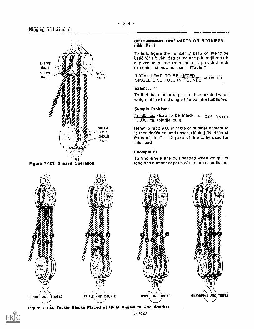
359
Rigging and Erection
SHEAVE
No. 1
SHEAVE
No. 5
rnFigure 7-101. Sheave Operation
SHEAVE
No 2
SHEAVE
No. 4
, 0/ , 0, 00
0! ;--)/...,\
DETERMINING LINE PARTS OR Rf..OUIRL:LINE PULL
Tc help figure the number of parts of line to beused for a given load or the line pull required fora given load, the ratio table is provided withexamples of how to use it (Table 7 -'
TOTAL_ LOAD TO BE LIFTEDSINGLE LINE PULL IN POUNDS RATIO
Exampi7
To find the ,thmber of parts of line needed whenweight of load and single line pull is establiShed.
Sample Problem:72,480 lbs. (load to be lifted) = 9.06 RATIO8,000 lbs. (Single pull)
Refer to ratio 9.06 in table or number nearest toit, then check column under heading "Nurnber ofParts of Line" 12 parts of line to be used forthis load.
Example 2:To find single line pull needed when weight ofload and number of parts of line are established.
I\ \ S\\ \
DOUBLE AND DOUBLE TRIPLE AND DOUBLE TRIPLE AND TRIPLE QUADRUPLE AND TRIPLE
\....._\ /
.." _i ....IFigure 7-102. Tackle Blocks Placed at Right Angles to One Another
:3 n

3g0
TABLE 7;14. LINE PARTS
NuriltAqof Partsof Line
Ratio forBronzeBushedSheaves
Ratio forAntiFriction
BearingSheaves
I 96 98
2 187 1943 2 75 2 884 359 3815 4 39 4.71
6 5 16 5 60
7 590 6478 660 7329 7 27 8 16
10 7 91 8 98
11 8 52 9 79
12 9 11 10.6
13 968 11414 10 2 12 1
15 10 7 12.9
16 11 2 13 6
17 II 1 14 3
18 12 2 15 0
19 12 6 15.7
20 13 0 16.4
21 13 4 17.0
22 13 8 17.7
23 14 2 18 3
24 I/1 5 18.9
Sample Problem:
68,000 lbs. (load to be lifted)6,60 (ratio of 8 part line)=-- 10,300 lbs (single line pull)
10,300 lbs. single line pull required to lift thisload on 8 parts of line.
LOADS ON SNATCH BLOCKS
The stress on a snatch block varies with thedegree of angle between the lead and load lines.When the two lines are parallel, 1,000 lbs. on thelead line results in a load of 2,000 lbs. on the
hObk. As the angle between the lines increases,the stress on the hook is reduced as illustratedin Figure 7-103: To determine the stress on ahook, multiply the pull on the lead line by aSuitable factor from Table 7-15 adding 10% forfriction.
tf0 2000 POUNDS 1840 POUNDS
45°
Figure 7-103.
TABLE 7.-15. SNATCH BLOCK ANGLE FACTORSAngle Factor Angle Factor Angle Factor Angle Factor Angle Factor Angle Factor
5° 1.998 35° 1.90 65° 1.69 95° 1.35 125° .92 155° .43
10' 1.99 40° 1.87 70° 1.64 100° 1.29 130° .84 160° 35
15° 1.98 45° 1.84 75° 1.58 105° 1.22 135° .76 165° 2t20° 1.97 50° 1.81 80° 1.53 110° 1.15 140° .68 12° .17
25° 1.95 55° 1.77 85° 1.47 115° 1.07 145' .60 175' .08
30° 1.93 60° 1.73 90° 1.41 12Q° 1.00 150° .52 180° .00

Rigging and Erection- 361 -
Pre r-2,7 on Sheave or Pulley8400 When a rope path is deflected by
a sheave, pulley or roller, pressure is,p laced on the bearings. The pressure will varydepending on the angle of deflection of the rope.
Placement of Shackle Block and NookBlock It is good practice to use a shackleblock as the upper one of a pair and a hookblock as the lower one. A shackle is muchstronger than a hook of the same size; and thestrain on the upper block is much greater thanon the lower one. The lower block supports onlythe load, while the upper block carries the loadas well as the hoisting strain. A hook is moreconvenient on the lower block because it can beattached to or detached from the load morereadily.
RIGGERS RULES OF THUMB
It is much easier to learn a simple formula thanto memorize complex tables and graphs.
These "Rules of Thumb" are reasonably ac-curate and most are on the "safe side" ofrecognized safety practices. But, it must beremembored, these formulas cioseestimates and are not intend.. opistcemanufacturer's specification:. criticalsituations.
FIBRE LINE
The lay of rope can be determined by runningyour thumb away from you along the strands inthe line. (If strands go to the right, it is a rightlay, etc.).
Coil line in the direction of the lay. (E.g., rightlay; clockwise, etc.).
Uncoil a new bail counterclockwise to avoidkinds.
Natural Fibre -- (Manila)
1. Breaking strength in tons = DO.2 x 42. Safe working load in tons = Dia.2 x 4
10
(safety factor = 10)
Synthetic Fibre (Nylon, Polypropylene)
1. Nylon = Approximately 21/2 times thestrength of manila.
2. Polypropylene = Approximately 11/2 timesthe strength of manila.
TACKLE SYSTEMS
1. Friction in a tackle system = Approximately8% per sheave @ 180'7' bend. 4% per sheave@ bend. (For wire rope tackle ap-proximately 6% for bronze bushed si,.:.:avesand 3% for ball bearing sheaves)
2. A Simple Tackle System = 1 line and one ormore blockS.
Mechanical advantage = Number of lines ontravelling block.
3. A Compound Tackle System = Two or moresimple tackle systems compounded.Mechanical advantage = The M.A. of eachsystem multiplied in series.
WIRE ROPE
(Determine lay; and coil like "Fibre Line")
1. Lang Lay Wire laid up in same directiOnas strands of rope.Regular Lay Wires layed up in oppositedirection as strands of rope.
2. Wire Core (I.W.R.C.) is approximately 10%stronger than fibre core.Galvanzing reduces strength approximately10%.
3 Breaking Strength in Tons = (Dia.)2 x 40 (For6 x 19 I.P.S. F.C.)
4. Safe Working Load in Tons = (Dia.)2 x 40 ±Safety Factor:
5. Safety Factors = Slings = 8Non rotating lines = 8
Cranes and Derricks = 6Derrick Guys . 5
Hoisting Tackle = 5
Guy Lines = 3.5
6. Broken Wires = Unsafe when 4% of totalwires in the rope are broken within thelength of one rope lay.
VV L7. Choker Stress x = T
N V
N = Number of ChokersW = Weight of load in poundsV = Vertical distance in feetL = Choker leg length; in feetT = Tension, in pounds
S. Sheaves The critical diameter of a
-3 6 8heave is 20 times the diameter of the rope.

- 362 -
9. Drums For spooling a drum you face thelead block and place the right or left hand,which ever corresponds with the lay of therope., palm down on the top of the drum foroverwind and the bottom -Nf the drum for un-derwind. The thumb will point to the flangewhere spooling begins.
10. Drum Capacity in feet =.2o18 x (A + B) x A x C. (in inches)
Rope Dia.2
11. Fleet Angle Maximum 4 on grooveddrums and 2 on smooth drums. ThediStance to the lead block shOuld never beless than 10 times the width of grooveddrums or 20 times the width of smoothdrums.
Fleet Angle
WIRE ROPE ATTACHMENTS (Safety factorof 5 included)
1. Crosby CHONumber of clips required 4 x ropediameter + 1.
Minimum spacing 6 x rope diameter:2. Hooks S.W.L. in tons = (Dia.)2 where
hook begins to curve or Diameter of eye ininches squared:
3. Shackles S.W.L. m tons = Diameter of pinin one fourth inches squared and divided bythree: (or select shackle pin one-eighth inchlarger than choker
4 Chains (Alloy Steel) S.W.L. in tons =chain stock (Dia.)2 x 6.
5. Turn Buckles S.W.L. in tons = bolt (Dia.)2x 3.
ESTIMATING WEIGHT OF STRUCTURALSTEEL: (One cubic foot = approximately 490lbs.)
<
1. Round Stock Approximate weight perlineal foot = (Dia.)2 v 8
3
2. Plate, Flat Bar, or St care Approximateweight per lineal foot = thickness timeswidth x 10 (All measurements in inches.)
3(Angles; Tees; or Wide Flange Beams can becalculated in the same manner by measuringthe legs, or web and flange individually asFlat Bar or Plate.)
SCAFFOLD PLANKS
Two inch planks (2 x 8,2 x 10, or 2 x 12) of fir orspruce in first class condition can be consideredsafe to support the weight of an average man fora "Span in Feet" that is equal to, or less than theplank "Width in Inches".
DERRICKS
GUY DERRICK
A guy derrick consists of a mast, a boom pivotedat the foot of the mast, guys and tackle (Figure7-104). The mast is generally longer than theboom and is mounted on vertical pins at the footand top so that the assembly of mast and boommay be rotated about a vertical axis. If the guysto the top of the mast clear the end of the boomthe derrick can be rotated through a full nifcle.The mast and boom may be made of timbc r
structural steel. Large derricks are mac& Jfhollow built up sections generally consisting offour angles and lacing bars forming a truss.
Hoisting tackle is suspended frnm the end of theboom and tackle is also provided for raising orlowering the boom in a vertical plane. Power issupplied by hand operated or engine drivenhoists. The derrick is rotated by a bull wheellocated at the base of the mast.
STIFF LEG DERRICK
the mast of the stiff leg derrick is held in the ver-tical position by two rigid inclined struts con-nected to the top of the mast (Figure 7-105). Thestruts are spread apart r.)0°-90u to provide sup-port in two directions and are attached to sillsextending from the bottom of the mast. The mastis mounted on vertical pins at its foot and top asin the case of the guy derrick. The mast andboom car ',rough an arc of about 270°. Thetackles 'oads and raising the boomare sirr )1- the guy derrick. Figure 7-106 illu_ if leg derrick with long sills.

Rigging and Erection363
fast Gudgeon Pinfop
Mast Bail
Guy
Lines
Mast
BOI1Wheel
Guide Sheaves
Upper MastHanger
Rooster Sheavefor Clamshell Work
y Lines
Bocm RaisingLine to Hoist
Boom Lines -**"
Boom
Guide Sheaves
Boom Bail
Boom Hanger
Boom Brace Rods
Lower MastGuide Sheaves
Lower MastSheaves
Bullwheel
Mast Bottom
Step
Step Sill Sheaves
Figure 7-104. Sections of a Guy Derrick
Boom
Hoist Line
Fall Block jt_and Hook
A stiff leg derrick equipped with a boom is boom. They are sometimes used in multi-storysuitable for yard use for unloading and trans- buildings surmounted by towers to hoistferring material whenever continuous materials to the roof of the main building to sup-operations are carried on within reach of its376Iy guy derricks mounted on the towers.

=364=
Stiff Leg
Mist Bail
Mast Top
Boom Li nes
Boom Bail --
Figure 7-105. Stiff Leg Derrick
Soho.
Ial I Bull Wheel
--.718/1* -------- Mast Bottom
Guide SheaveSill
BUIIWheel
Guide Sheaves0 II
ws. :iveo "eoloo-0000eIke s arams-a
Stiff Le
Gudgeon Pin
Lower MastGuide Sheaves
Lower MastSheaves
Stiff leg Sill
Mast Step
Boom Line
Mast BailUpper Mast
Sheave
Mast
A M.Step
Bullwheel
Mast Bottom
Boom
Guide Sheaves
Figure 7-106. Section of Stiff Leg Derrick with Long Sills
Boom
Splice
Block and Hook
4.5.Boom Bail
4,40
Air HoistLine
Block and Hook
Boom Brace Rods
-44

355Rigging and Erection
GIN POLE
The gin pole (Figure 7-107) consists of anupright spar guyed at the top to maintain it in avertical position and is equipped with suitablehoisting tackle The spar may be of round orsquare timber, heavy wall pipe, a wide flangebeam section or a built up section consisting ofangles and lacing bars. The load may be hoistedby hand tackle or by hand or engine drivenhoists.
A gin pole is a very handy and versatile piece ofequipment for lifting. all types of compaN:tivelylight loads: To get _maximum _use out of a ginpole: it should be rigged with a minimum of fourguys:_. with wire re..)e pendants and manila ropetackles _between pendants. and the an-chorages and swivel plates top and bottom.These can then .be leaned at various angles andturned to lift from all sides.
The gin pole is used mostly for erection work ofease of rigging. moving and operating. It is
suitable for raising loads of medium weight toheights of 1c--50' where a vertical lift is required.
ProcedureRefer to F .lure 7-108 for Steps 1, this procedure.
Siep 1. Using any suitable scale, draw asketch as shown in A.Line TS represents the guyLine RS represents the gin pole
step 2. With a given load of 4,000 !b., let1/4" =1.000 lb. and draw a vCiticalline VU representing the load (1"long) as in B.From U, extend a line UV! arallel tcTS (from A) to represent the goy, anda line VW parallel to RS (from A) torepresent the gin pole
Step 3. To develop C, draw a line VW parallelto, and the same length as VW (fromB). Drop a vertical line down from W,and draw the line VX parallel to TR(from A).
Swivel Plate
Wire Rope: .'endant
Mre RopePeri;Jht
Wire Rope Pendant Wire RopePendant
Snatch Block
Figure 7-1C7. Gin Pole
372
To Power

= 366
Figure 7-108. Datermining the Kok at theHeel .zif a Gill Pole
Mea.::::r the length VX, and, using thescale 1/4" = 1.000 lb.. calculate theamount of kick on the pole.
A-FRAME DERRICK
An A-Frame (or Shear Leg) derrick is a versatilehoisting device, requiring only two back guys.and one lazy guy in front 7nr support (Figure 7-'09):
For light loaas. a small A-Frame derrick can bequickly constructed by drilling a hole throughtwo pieces of sq. r:re timber and bolting throughthe holes. A wire rope choker is put around thetop of the poles with the eye hanging down to at-tach the block. When a load is suspended fromthe block. the choicer tightens to hold thecrossed members more securely.
MOBILE CRANES
Mobile cranes are mechanical lifting devicesthat can be relocated without disassembly: Theymay be classified into two main types: 1: thosemounted on metal tracks (Figure 7-110) and 2:those mounted on rubber tirP^ (Figure 7-111):Figure 7-112 the parts of a mobilecrane:
rgure 7-109. A-Frame Derrick
0'1
Figure 7-110. Mobile Crane on Tracks
Two types of booms (Figure 7-113) With respectto the capability on the crane are identified:1. Conventional booms may be lowered, raised
or swung sideways. however, the assembledlength does not change:
2. Hydraulic booms may be lowered: raised orswung sideways: and the length can be ex-tended or retracted without reassembly:
The choice of boom is based upon the functionalrequirements of the crane for the job. Where
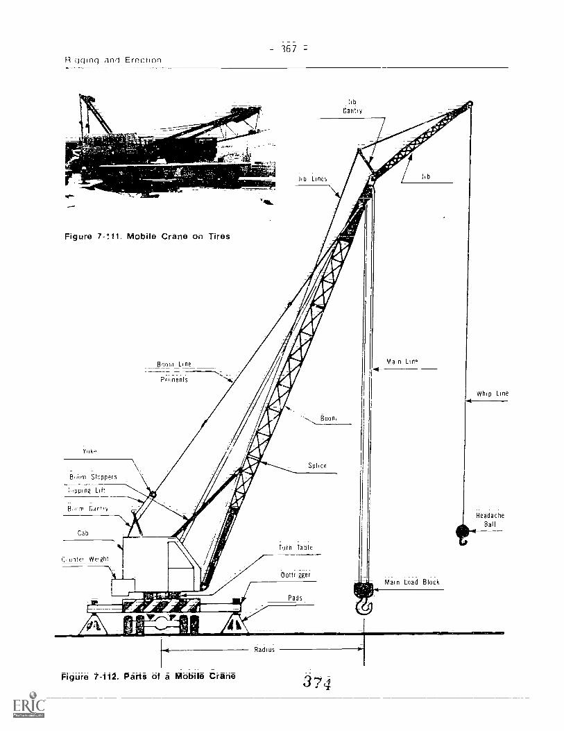
67R,c)dind and Erection
Figure 7=111. Mobile Crane on Tires
YOlw
Birn Stoppers
1 pping Lift
B.)ni Gantry
Cab
Bow Line
inents
ho Lines
libGantry
Main Lino
-4Whip Line
Headache
Ball
(unter WeiRht
Main toad Block
Figure 7-112. Parts of a Mobile Crane
Radius
34

368 -
HYDRA', 'C BOOM
,.=,-
s_ .CONVENTIONAL BOOM
Figure 7-113. Crane Booms
heavy or exceptionally high lifts are involved,the conventional boom is used. Where the loadsare lighter and more set-ups are required forshorter lifts, the hydraulic boom is more suitable.
When an hydraulic mobile crane is delivered to ajobsite, it is almost immediately ready to go intooperation (Figure 7-114). It need only be "spot-
st,Figure 7 -114.7-114; Crane Arriving on The Job,
Raising Gantry to Operating Position3 7-*-
ii...4

- 369Rigging and Erection
ted," the outriggers extended and the crane job location. Crane assembly at the jobsitelevelled; before the first lOad can be lifted. within the jurisdiction of the erection Boiler-
maker.BOOM ASSEMBLY
Figures 7 -114 to 7-118 illustrate a typicalOn The other hand: a conventional_ type mobile sequence in the assembly of a conventionalcrane arrives in separate units._ The boom corn- mobile crane, from arrival on the job to Workponents. outriggers. counterweights and main ready:block must be offloaded (usually assisted by an(n -site hydraulic crane). and assembled on the
INSTALL FLOAT PADS
-,-.71111
INSTALLING REAR COUNTERWEIGHT WITH SECOND RIG
Figure 7-115. Floatpads and Counterweights
INSTALLING FRONT COUNTERWEIGHT
CRANE SAFETY AND SIGNALS
Assembly Precautions
1. Chetk all outrigger assemblies.2. Check all boorn section', for damage.3. AlWays install boom pins from the inside of
tn2 boOm to the outside.4 Ensure all boom pins are secured 'ith cotter
pins.
5. Before raising boom. mach, .,t belevelled, outriggers fully extended and rub-ber off the ground.
6: When disassembling boom sections, blockthe section to be removed.
37-6

370 -
A
MOV/Nt't BOOM OFF TRUCK
POSITIONING FOR PINNING
INSERTING TOP PINS FIRST
Figure 7-116. Assembling the Boom
INSERTING BOTTOM PINS
PINS SECURED BY COTTER PIN
JOINING OTHER SECTIONS
3

-= 371Rigging and Erection
YOKE READIED FOR PENDANT LINES
-PENDANT LINES ATTACHED
4110rMAIN LINE REEFED TO MAIN BLOCK
Figure 7-117. Attaching the Lines
WEDGE SOCKET ATTACHED TO MAIN BLOCKS
11111KIIIC
ea.
X
TERMINAL
END OF MAIN LINE FITTED TO WEDGE SOCKET3 6

= 372
sr
a'
Figura 7-118. t-P.:,om Rais6d and CarrieMoved to Area of Lift
Safety During Crane Operation
1. One mar. only will be designated assignalman. The signalman must be in fullview of the crane operator at .-,11 times.Crane signals are Illustrated in The W.C.B.material in Figure 7-119.
2. When locating the machine. the loll-owingmust be observed:a. As level a path as possible must be
folloWed when moving the Machine;avoid slopes and rough terrain.
b. The bobrri must be in a raised positionwhen the crane is travelling.
c. PartiCularly for larger machines, thespeed of travel must be slow.
d. When "spotting' the crane. to ensurefull rated capacity. the machine mustbe levelled, outriggers fully extended.and all rubber off the ground.
e Be aware of all power lines in the areawhere the crane is spotted:
3 Know the weight of all loads (includingweight of any rigging accessories):
4. Measure (rather than es:imate) tl.emachine's load radius when ,nakingcapacity lifts:
5: Avoid effects of "shock loadir-;" to riggingand equipmen;: by raising and loweringioads slowly:
6: Always use a tag line to control the loadwlicsn in the air.Whe. hoon,ing dow-, o swinging with aload: always keep t:,:e iad as close to theground as pos:.-3.ble.
When swinging. always ensure that thecounterweight area of swing has:a) sufficient clearance to clear ob-
structions.b) been barricaded wherever there is a
possibility of a worke ieing crushed.
9. Keep all personnel out from under load.
10. No one is lowed to ride the load under anycircumstances.
11. Snub heavy loads to the machine whentravelling with 2 ITad.
12. When operations ceas. for the day. it is ad-visable to "tie down' the boom by attachinga choker from the .-ook in usestatciry object with only enough t,-.1n:onto i:rdnobilizo the boom.

Rigging and Erection- 373
Standard Hand Signals for ControllingCrane Operations, Crawler, Locomotive and Truck Cranes
HOIS r .Pith forearm verticallorefinder pointing up move_nand ni small horizontal circles
LOWER With arm extendeedownward forefinger pointingclown move hand in smallhorizontal circles
USE MAIN HOIST Tap fist onhead, then use regular signals
USE WHIPLINEHoist' Tao elbow with onenand then use regular signals
RAISE BOOM Arm extendedfingers closed thumb pointingupward
LOWER BOOM Arm extended.fingers closed. thumb pointingdoWnwarC
,.!OVE SLOWLY Use one handIC' 'live ,ioy motion signal andplace other nand motionless InIron of nand giving the motion, a-_-)! HOiSI Slowly shown asn..1Mple,
L..
RAISE THE BOOM AND LOWER THELOAD Arm extended fingersclosed thumb pointing upwardother arm bent slightly withforefinger pointing down androtate hand in horizontal circles
LOWER -THE BOOM AND RAISE THELOAD Aern eyitendea. finger7closed thumb pOinting downwordother arm with fOrearm verticalforefinger pointing upward androtate nand in horizontal circles
(continued)
Figurs 7-119. Crane Signals35v

=374=
Standard Hand Signals for Co...rollingCrane Operations, Crawler, Locomotive and Truck Cranes
STOP Both arms outstretchedat Sides hoozontallyfingers outstretched
TRAVEL Arm e,tended forw-i,ha open and slightly raisedmake bushing motion indirection of travel
DOG EVFRYTI-Itiq5 Clasp handsif. front of body
TRAVEL (Both Tracks) Useboth fists 'in front of bodymaking a circular ,notion abouteach other indicating directionof travel. forvvard n baCkvvardFor crawler cram- only I
TRAVEL -)ne Track) Lock the trackn side ir. ticated by raised fist
TIvel track in directionby circular motion of other
eated vertically in Iron. ofborlv ,For crawler cranes r
EXTEND BOOM (Tele-scoping Booms) Bothin front of body with thumbspointing outward One handsignal may be used
RETRACT BOOM (Tele-scoping Booms) Both fistsin front n' body with thumbspointing toward each otherOne hand ,ignal may heiised
Figure 7-119. Cranit Signals (continued)
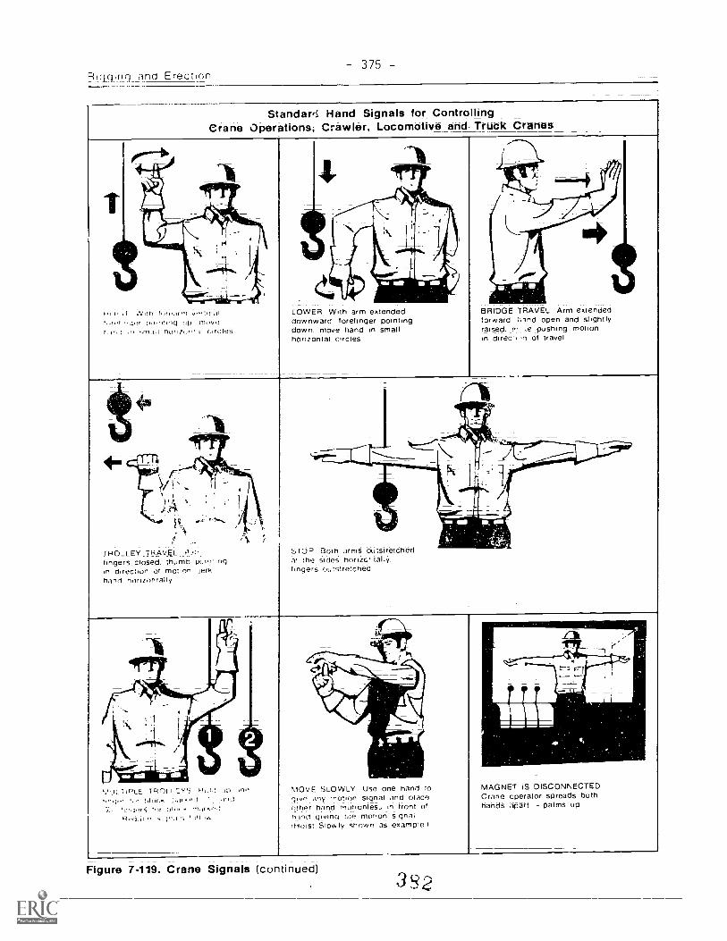
R!ciquiri rind Erection3 75
StandaM Hand Signals for ControllingCrane Operations, Crawler, Locomotive and Truck Cranes
vei",,a(;An ITIOVt.!
r,,r; 1 .n hurquii d circles
TROLLEY TRAVELfingers closed. thumb pt.iiy rigin direction of motion jerkhand horizdntally
COWER With arm extended BRIDGE TRAVEL Arm extendeddownward forefinger pointing forward :,-Inct open and slightlydown move hand in small raised. ri :e pushing motionhorizontal circles in direr: in of travel
STOP Both arms outstretchedat the sides horizci tallyfingers outstretched
TiPLE TPOLI"d-
-nark0-1
MOVE SLOWLY Use one hand togive any 'notion signal and placeother hand inutionles:: in front ofhand giving toe motion signaliHoist Slowly shown as example I
Figure 7-119. Crane Signals (continued)
MAGNET iS DISCONNECTEDCrane Operator spreads bothhands apart - palms up
3 S 2

= 3 76 -=
Standard -I Signals for ControllingCrane Operations, u-vakioad arfil Gantry Cranes
r t
,NI I f!, DrICONNECTEDan opera !or spreads twth
iolr palms op
OPEN CLAM SHELL BUCKETarm extended palm downopen hand
HOIST SLOWLY TO CLEARFOULED LINE Hands crossed
front above shouldershogers relaxed
BOOM UP AND LOWERTHE LOAD One hand
JSE CLAM SHELL BUCKET.tended palm down
os nand
BOOM DOWN ANDRAISE THE LOADme hand
WHIP LINE One hand
Figure 7-11; Crane Signals (cor tinued)