hoshizaki€¢ do not place objects on top of the icemaker. • the storage bin is for ice use only....
TRANSCRIPT

Hoshizaki
“A Superior Degree of Reliability”
www.hoshizaki.com
Models KM-320MAH-E KM-515MAH-E KM-650MAH-E
Modular Crescent Cuber
Hoshizaki America, Inc.
SERVICE MANUAL
Number: 73170Issued: 11-13-2008Revised: 3-22-2012
89/33673/23

2
WARNINGOnly qualified service technicians should install and service the icemaker. To obtain the name and phone number of your local Hoshizaki Certified Service Representative, visit www.hoshizaki-europe.com. No service should be undertaken until the technician has thoroughly read this Service Manual. Failure to service and maintain the icemaker in accordance with this manual will adversely affect safety, performance, component life, and warranty coverage and may result in costly water damage. Proper installation is the responsibility of the installer. Product failure or property damage due to improper installation is not covered under warranty.
Hoshizaki provides this manual primarily to assist qualified service technicians in the service and maintenance of the icemaker. Should the reader have any questions or concerns which have not been satisfactorily addressed, please call the appropriate Hoshizaki Service Office:
UK/Ireland - Hoshizaki UKTEL : +44 (0)845 456 0585FAX: +44 (0)132 283 8331
Holland - Hoshizaki EuropeTEL : +31 (0)20 6918499FAX: +31 (0)20 6918768
Belgium/Luxemburg - Hoshizaki BelgiumTEL : +32 (0)2 7123030FAX: +32 (0)2 7123031
Germany/Switzerland/Austria - Hoshizaki DeutschlandTEL : +49 (0)2154 92810FAX: +49 (0)2154 928128
France - Hoshizaki FranceTEL : +33 (0)1 48639380FAX: +33 (0)1 48639388
Other countries - Hoshizaki EuropeTEL: +31 (0)20 6918499FAX: +31 (0)20 6918768
Web Site: www.hoshizaki-europe.com
NOTE: To expedite assistance, all correspondence/communication MUST include the following information:
•ModelNumber________________________
•SerialNumber________________________
•Completeanddetailedexplanationoftheproblem.

3
CONTENTSImportant Safety Information ................................................................................................. 5I. Specifications ...................................................................................................................... 7
A. KM-320MAH-E ............................................................................................................. 7B. KM-515MAH-E .............................................................................................................. 8C. KM-650MAH-E .............................................................................................................. 9
II. General Information ......................................................................................................... 10A. Construction ................................................................................................................ 10
1. KM-320MAH-E ....................................................................................................... 102. KM-515MAH-E .......................................................................................................113. KM-650MAH-E ...................................................................................................... 12
B. Sequence of Operation ............................................................................................... 131. Sequence Cycles and Shutdown ........................................................................... 13
a) "E" Control Board ............................................................................................. 13b) "G" Control Board ............................................................................................ 15
2. Sequence Flow Chart ............................................................................................ 17a) "E" Control Board: ............................................................................................ 17b) "G" Control Board: ............................................................................................ 18
C. Control Board .............................................................................................................. 191. Control Board Layout ............................................................................................. 20
a) "E" Control Board ............................................................................................ 20b) "G" Control Board ........................................................................................... 21
2. LED Lights and Audible Alarm Safeties ................................................................. 22a) "E" Control Board ............................................................................................ 22b) "G" Control Board ........................................................................................... 23
3. Controls and Adjustments ...................................................................................... 24a) Default Dip Switch Settings ............................................................................... 24b) Harvest Timer (S4 dip switch 1 & 2) ................................................................. 25c) Pump-Out Timer (S4 dip switch 3 & 4) .............................................................. 25d) Pump-Out Frequency Control (S4 dip switch 5 & 6) ......................................... 26e) Bin Control Selector/Harvest Pump Timer (S4 dip switch 7) ............................. 26f) Factory Use (S4 dip switch 8) ............................................................................ 27g) Freeze Timer (S4 dip switch 9 & 10) ................................................................. 27h) Float Switch Selector (S5 dip switch 1): "G" Control Board .............................. 28i) Refill Counter (S5 dip switch 2 through 5): "G" Control Board ........................... 28
D. Control Switch ............................................................................................................. 28
IMPORTANTThis manual should be read carefully before the icemaker is serviced. Read the warnings and guidelines contained in this booklet carefully as they provide essential information for the continued safe use, service, and maintenance of the icemaker. Retain this booklet for any further reference that may be necessary.

4
III. Technical Information ...................................................................................................... 29A. Water Circuit and Refrigeration Circuit ........................................................................ 29B. Wiring Diagram ............................................................................................................ 30
1. Thermostatic Bin Control ....................................................................................... 302. Mechanical Bin Control ......................................................................................... 31
C. Performance Data ....................................................................................................... 321. KM-320MAH-E ....................................................................................................... 322. KM-515MAH-E ...................................................................................................... 333. KM-650MAH-E ...................................................................................................... 34
IV. Service Diagnosis ........................................................................................................... 35A. Diagnostic Procedure .................................................................................................. 35B. Control Board Check ................................................................................................... 39C. Bin Control Check ....................................................................................................... 40
1. Thermostatic Bin Control Check ............................................................................ 402. Mechanical Bin Control Check and Cleaning ....................................................... 41
a) Mechanical Bin Control Check .......................................................................... 41b) Mechanical Bin Control Cleaning ...................................................................... 42
D. Float Switch Check and Cleaning ............................................................................... 431. Float Switch Check ................................................................................................ 432. Float Switch Cleaning ............................................................................................ 44
E. Thermistor Check ........................................................................................................ 45F. Diagnostic Charts ........................................................................................................ 46
1. No Ice Production ................................................................................................... 462. Freeze-Up .............................................................................................................. 473. Low Ice Production ................................................................................................ 49
V. Replacement of Components .......................................................................................... 50A. Service for Refrigerant Lines ....................................................................................... 50
1. Refrigerant Recovery ............................................................................................. 502. Brazing .................................................................................................................. 513. Evacuation and Recharge (R-404A) ...................................................................... 52
B. Important Notes for Component Replacement ............................................................ 53VI. Cleaning and Maintenance ............................................................................................ 54
A. Cleaning and Sanitizing Instructions ........................................................................... 541. Cleaning Procedure ................................................................................................ 552. Sanitizing Procedure - Following Cleaning Procedure ........................................... 56
B. Maintenance ................................................................................................................ 57C. Preparing the Icemaker for Periods of Non-Use .......................................................... 58
VII. Disposal ......................................................................................................................... 59

5
Important Safety InformationThroughout this manual, notices appear to bring your attention to situations which could result in death, serious injury, damage to the icemaker, or damage to property.
WARNING Indicates a hazardous situation which could result in death or serious injury.
NOTICE Indicates a situation which could result in damage to the icemaker or property.
IMPORTANT Indicates important information about the use and care of the icemaker.
WARNINGThis icemaker should be destined only to the use for which it has been expressly conceived. Any other use should be considered improper and therefore dangerous. The manufacturer cannot be held responsible for injury or damage resulting from improper, incorrect, and unreasonable use. Failure to service and maintain the icemaker in accordance with this manual will adversely affect safety, performance, component life, and warranty coverage and may result in costly water damage.To reduce the risk of death, electric shock, serious injury, or fire, follow basic precautions including the following:
•Onlyqualifiedservicetechniciansshouldinstallandservicethisicemaker.
•Electricalconnectionmustmeetnational,state,andlocalelectricalcoderequirements. Failure to meet these code requirements could result in death, electric shock, serious injury, fire, or severe damage to equipment.
•Thisicemakerrequiresanindependentpowersupplyofpropercapacity.Seethenameplate for electrical specifications. Failure to use an independent power supply of proper capacity can result in a tripped breaker, blown fuses, damage to existing wiring, or component failure. This could lead to heat generation or fire.
• THE ICEMAKER MUST BE EARTHED (GROUNDED). 220-240VAC UK and the Republic of Ireland: This appliance is equipped with a non-rewirable BSI BS-1363 three-prong 13A fused earthing (grounding) plug to reduce the risk of potential shock hazards. It must be plugged into a properly earthed (grounded), independent 3-prong mains socket. If the mains socket is not compatible, it is your personal responsibility to have a qualified electrician replace it with a properly earthed (grounded), independent, compatible 3-prong mains socket. Do not remove the earth (ground) prong or fuse from the plug and do not use an adapter plug. The BSI BS-1363 three-prong 13A fused earthing (grounding) plug must never be used without a fuse cover being fitted. Failure to follow these instructions may result in death, electric shock, or fire.
• 220-240VAC Continental: If the power cord and/or non-rewirable plug should need to be fitted or replaced, it should only be done by a qualified service technician. Failure to follow these instructions may result in death, electric shock, or fire.
•Toreducetheriskofelectricshock,donottouchthecontrolswitchorplugwithdamp hands.
6
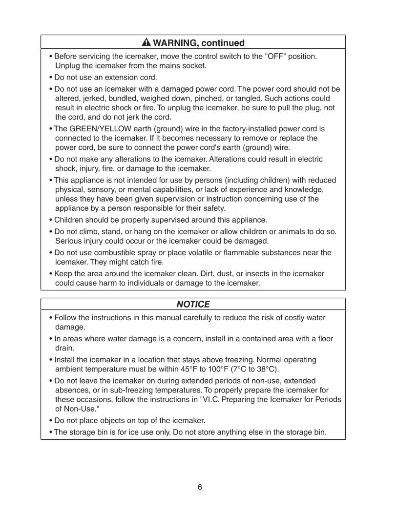
WARNING, continued•Beforeservicingtheicemaker,movethecontrolswitchtothe"OFF"position.
Unplug the icemaker from the mains socket.
•Donotuseanextensioncord.
•Donotuseanicemakerwithadamagedpowercord.Thepowercordshouldnotbealtered, jerked, bundled, weighed down, pinched, or tangled. Such actions could result in electric shock or fire. To unplug the icemaker, be sure to pull the plug, not the cord, and do not jerk the cord.
•TheGREEN/YELLOWearth(ground)wireinthefactory-installedpowercordisconnected to the icemaker. If it becomes necessary to remove or replace the power cord, be sure to connect the power cord's earth (ground) wire.
•Donotmakeanyalterationstotheicemaker.Alterationscouldresultinelectricshock, injury, fire, or damage to the icemaker.
•Thisapplianceisnotintendedforusebypersons(includingchildren)withreducedphysical, sensory, or mental capabilities, or lack of experience and knowledge, unless they have been given supervision or instruction concerning use of the appliance by a person responsible for their safety.
•Childrenshouldbeproperlysupervisedaroundthisappliance.
•Donotclimb,stand,orhangontheicemakerorallowchildrenoranimalstodoso.Serious injury could occur or the icemaker could be damaged.
•Donotusecombustiblesprayorplacevolatileorflammablesubstancesneartheicemaker. They might catch fire.
•Keeptheareaaroundtheicemakerclean.Dirt,dust,orinsectsintheicemakercould cause harm to individuals or damage to the icemaker.
NOTICE•Followtheinstructionsinthismanualcarefullytoreducetheriskofcostlywater
damage.
•Inareaswherewaterdamageisaconcern,installinacontainedareawithafloordrain.
•Installtheicemakerinalocationthatstaysabovefreezing.Normaloperatingambient temperature must be within 45°F to 100°F (7°C to 38°C).
•Donotleavetheicemakeronduringextendedperiodsofnon-use,extendedabsences, or in sub-freezing temperatures. To properly prepare the icemaker for these occasions, follow the instructions in "VI.C. Preparing the Icemaker for Periods of Non-Use."
•Donotplaceobjectsontopoftheicemaker.
•Thestoragebinisforiceuseonly.Donotstoreanythingelseinthestoragebin.

7
I. Specifications
A. KM-320MAH-E
Note: We reserve the right to make changes in specifications and design without prior notice.
AC SUPPLY VOLTAGE 220-240/50/1AMPERAGE 3.5 A (5 Min. Freeze at 109°F/WT 59°F)MINIMUM CIRCUIT AMPACITY 15 AMAXIMUM FUSE SIZE 15 AAPPROXIMATE ICE PRODUCTION Ambient WATER TEMP. (°F)PER 24 HR. Temp. (°F) 50 70 90 lbs./day (kg/day) 70 *293 (133) 275 (125) 255 (116) Reference without *marks 80 279 (127) 252 (114) 234 (106)
90 275 (125) *232 (105) 213 (97)100 273 (124) 228 (103) 196 (89)
FOR THE EUROPEAN MARKET 10/10°C 20/15°C 30/25°CICE CAPACITY lbs./day (kg/day) 346 (157) 303 (137) 236 (107)SHAPE OF ICE Crescent CubeICE PRODUCTION PER CYCLE 8 lbs. (3.6 kg) 360pcs.APPROXIMATE STORAGE CAPACITY N/AELECTRIC & WATER CONSUMPTION 90/70°F 70/50°F ELECTRIC W (kWH/100 lbs.) 710 (7.3) 650(5.3) WATER gal./24HR (gal./100 lbs.) 52(22.2) 117(40.1)EXTERIOR DIMENSIONS (WxDxH) 22"x27-3/8"x30-5/16" (560x695x770 mm)EXTERIOR FINISH Stainless Steel, Galvanized Steel (Rear) WEIGHT Net 153 lbs. (69 kg), Shipping 175 lbs. (79 kg)CONNECTIONS - ELECTRIC Power Cord - Connection - WATER SUPPLY Inlet 1/2" FPT - DRAIN Outlet 3/4" FPT
3/8" OD Hard TubeCUBE CONTROL SYSTEM Float SwitchHARVESTING CONTROL SYSTEM Hot Gas and Water, Thermistor and TimerICE MAKING WATER CONTROL Timer Controlled. Overflow PipeCOOLING WATER CONTROL N/ABIN CONTROL SYSTEM Thermostatic or Mechanical Bin ControlCOMPRESSOR Hermetic, Model ASE32C3E-CAZ-254 CONDENSER Air-Cooled , Fin and tube typeEVAPORATOR Vertical type, Stainless Steel and CopperREFRIGERANT CONTROL Thermostatic Expansion ValveREFRIGERANT CHARGE R404A, 1 lb. 4.3 oz. (575g)DESIGN PRESSURE High 467PSIG, Low 230PSIGP.C. BOARD CIRCUIT PROTECTION High Voltage Cut-out ( Internal )COMPRESSOR PROTECTION Auto-reset Overload Protector ( Internal )REFRIGERANT CIRCUIT PROTECTION Auto-reset High Pressure Control SwitchLOW WATER PROTECTION Float SwitchACCESSORIES -SUPPLIED N/A -REQUIRED Ice Storage BinOPERATING CONDITIONS VOLTAGE RANGE 198 - 254 V
AMBIENT TEMP. 45 -100° FWATER SUPPLY TEMP. 45 - 90° FWATER SUPPLY PRESSURE 10 - 113 PSIG
ENG.F-011.1.0205

8
B. KM-515MAH-E
Note: We reserve the right to make changes in specifications and design without prior notice.
AC SUPPLY VOLTAGE 220-240/50/1AMPERAGE 7.14 A ( 5 Min. Freeze AT 109°F / WT 59°F)MINIMUM CIRCUIT AMPACITY 15AMAXIMUM FUSE SIZE 15 AAPPROXIMATE ICE PRODUCTION Ambient WATER TEMP. (°F)PER 24 HR. Temp.(°F) 50 70 90 lbs./day ( kg/day ) 70 *513 (233) 482 (219) 441 (200) Reference without *marks 80 490 (222) 442 (200) 401 (182)
90 482 (219) *408 (185) 366 (166)100 474 (215) 398 (181) 328 (149)
FOR THE EUROPEAN MARKET 10/10°C 21/15°C 30/25°CICE CAPACITY lbs./day ( kg/day ) 582 (264) 528 (239) 406 (184)SHAPE OF ICE Crescent CubeICE PRODUCTION PER CYCLE 10.2 lbs. (4.6 kg) 480pcs.APPROXIMATE STORAGE CAPACITY N/AELECTRIC & WATER CONSUMPTION 90/70°F 70/50°F ELECTRIC W (kWH/100 lbs.) 1200(7.1) 1080(5.1) WATER gal./24HR (gal./100 lbs.) 108(26.5) 159(31.1)EXTERIOR DIMENSIONS (WxDxH) 22" x 27-3/8" x 30-5/16" (560 x 695 x 770 mm)EXTERIOR FINISH Stainless Steel, Galvanized Steel (Rear) WEIGHT Net 151 lbs. (68 kg), Shipping 175 lbs. (79 kg)CONNECTIONS - ELECTRIC Power Cord - Connection - WATER SUPPLY Inlet 1/2" FPT - DRAIN Outlet 3/4" FPT
3/8" OD Hard TubeCUBE CONTROL SYSTEM Float SwitchHARVESTING CONTROL SYSTEM Hot Gas and Water, Thermistor and TimerICE MAKING WATER CONTROL Time Controlled. Overflow PipeCOOLING WATER CONTROL N/ABIN CONTROL SYSTEM Thermostatic or Mechanical Bin ControlCOMPRESSOR Hermetic, Model RST64C1E-CAZ-202 CONDENSER Air-Cooled , Fin and Tube TypeEVAPORATOR Vertical Type, Stainless Steel and CopperREFRIGERANT CONTROL Thermostatic Expansion ValveREFRIGERANT CHARGE R404A, 1 lb. 2.5 oz. L33 (525g)DESIGN PRESSURE High 467PSIG, Low 230PSIGP.C. BOARD CIRCUIT PROTECTION High Voltage Cut-Out ( Internal )COMPRESSOR PROTECTION Auto-Reset Protector ( Internal )REFRIGERANT CIRCUIT PROTECTION Auto-Reset High-Pressure SwitchLOW WATER PROTECTION Float SwitchACCESSORIES -SUPPLIED N/A -REQUIRED Ice Storage BinOPERATING CONDITIONS VOLTAGE RANGE 198-254VAC
AMBIENT TEMP. 45 -100° FWATER SUPPLY TEMP. 45 - 90° FWATER SUPPLY PRESSURE 10 - 113 PSIG
ENG.F-011.1.0205

9
C. KM-650MAH-E
Note: We reserve the right to make changes in specifications and design without prior notice.
AC SUPPLY VOLTAGE 220-240/50/1AMPERAGE 6.8 A ( 5 Min. Freeze AT 109°F / WT 59°F)MINIMUM CIRCUIT AMPACITY 15 AMAXIMUM FUSE SIZE 15 AAPPROXIMATE ICE PRODUCTION Ambient WATER TEMP. (°F)PER 24 HR. Temp.(°F) 50 70 90 lbs./day ( kg/day ) 70 *653 (296) 610 (277) 558 (253) Reference without *marks 80 620 (281) 554 (251) 506 (229)
90 610 (277) *507 (230) 456 (207)100 602 (273) 495 (225) 409 (186)
FOR THE EUROPEAN MARKET 10/10°C 20/15°C 30/25°CICE CAPACITY lbs./day (kg/day) 734 (333) 603 (274) 535 (243)SHAPE OF ICE Crescent CubeICE PRODUCTION PER CYCLE 14 lbs. (6.4 kg) 720pcs.APPROXIMATE STORAGE CAPACITY N/AELECTRIC & WATER CONSUMPTION 90/70°F 70/50°F ELECTRIC W (kWH/100 lbs.) 1200(5.7) 1090(4.0) WATER gal./24HR (gal./100 lbs.) 94(18.5) 162(24.8)EXTERIOR DIMENSIONS (WxDxH) 22" x 27-3/8" x 37-7/16" (560 x 695 x 950 mm)EXTERIOR FINISH Stainless Steel, Galvanized Steel (Rear) WEIGHT Net 169 lbs. (77 kg), Shipping 200 lbs. (91 kg)CONNECTIONS - ELECTRIC Power Cord - Connection - WATER SUPPLY Inlet 1/2" FPT - DRAIN Outlet 3/4" FPT
3/8" OD Hard TubeCUBE CONTROL SYSTEM Float SwitchHARVESTING CONTROL SYSTEM Hot Gas and Water, Thermistor and TimerICE MAKING WATER CONTROL Time Controlled. Overflow PipeCOOLING WATER CONTROL N/ABIN CONTROL SYSTEM Thermostatic or Mechanical Bin ControlCOMPRESSOR Hermetic, Model RST64C1E-CAZ-202 CONDENSER Air-Cooled , Fin and Tube TypeEVAPORATOR Vertical Type, Stainless Steel and CopperREFRIGERANT CONTROL Thermostatic Expansion ValveREFRIGERANT CHARGE R404A, 1 lb. 6.6 oz. (640g)DESIGN PRESSURE High 467PSIG, Low 230PSIGP.C. BOARD CIRCUIT PROTECTION High Voltage Cut-Out ( Internal )COMPRESSOR PROTECTION Auto-Reset Protector ( Internal )REFRIGERANT CIRCUIT PROTECTION Auto-Reset High-Pressure SwitchLOW WATER PROTECTION Float SwitchACCESSORIES -SUPPLIED N/A -REQUIRED Ice Storage BinOPERATING CONDITIONS VOLTAGE RANGE 198-254VAC
AMBIENT TEMP. 45 -100° FWATER SUPPLY TEMP. 45 - 90° FWATER SUPPLY PRESSURE 10 - 113 PSIG
ENG.F-011.1.0205

10
II. General Information
A. Construction
1. KM-320MAH-E
Thermostatic Bin ControlAuxiliary Code U-0 and Earlier
Control Switch
Expansion Valve
Compressor
Float Switch
Water Pump
Control Box
Drier
Fan Motor
Hot Gas Valve
Condenser
Water Supply PipeSpray Tubes
Main Transformer(230V→115V)
High-Pressure Switch
Strainer
Thermistor
Evaporator
Inlet Water Valve
Power Cord with Fused Plug(250V, 13A fuse)
Mechanical Bin ControlAuxiliary Code U-1 and Later
U-0 and Earlier
U-1 and Later

11
2. KM-515MAH-E
Main Transformer(230V→115V)
Control Switch
Expansion Valve
Compressor
Float Switch
Water Pump
Control Box
Drier
Fan Motor
Hot Gas Valve
Condenser
Water Supply PipeSpray Tubes
High-Pressure Switch
Strainer
Thermistor
Liquid Line Valve
Evaporator
Inlet Water Valve
Thermostatic Bin ControlAuxiliary Code U-1 and Earlier
Mechanical Bin ControlAuxiliary Code U-2 and Later
U-1 and Later
U-0 and Earlier
Power Cord with Fused Plug(250V, 13A fuse)

12
3. KM-650MAH-E
Main Transformer(230V→115V)
Control Switch
Thermostatic Expansion Valve
Compressor
Float Switch
Water Pump
Control Box
Drier
Fan Motor
Hot Gas Valve
Condenser
Water Supply PipeSpray Tubes
High-Pressure Switch
Strainer
Thermistor
Evaporator
Inlet Water Valve
Thermostatic Bin ControlAuxiliary Code U-0 and Earlier
Mechanical Bin ControlAuxiliary Code U-1 and Later
U-1 and Later
U-0 and Earlier
Power Cord with Fused Plug(250V, 13A fuse)

13
B. Sequence of Operation
1. Sequence Cycles and Shutdown
a) "E" Control Board
KM-320MAH-E and KM-650MAH-E Auxiliary Code U-0 and Earlier
KM-515MAH-E Auxiliary Code U-1 and Earlier
The steps in the sequence are as outlined below. When power is supplied, CB red "POWER OK" LED comes on. There is a 5-second delay before startup. Note that the order of the component LEDs from the outer edge of CB is 1, 4, 3, 2.
(1) 1-Minute Fill CycleLED 4 is on. WV energizes and the fill period begins. After 1 minute, CB checks for a closed F/S. If F/S is closed, the harvest cycle begins. If not, WV remains energized through additional 1-minute fill cycles until water enters the water tank and F/S closes. This serves as a low water safety to protect PM.
(2) Initial Harvest CycleLEDs 1, 4, and 2 are on. WV remains energized, Comp and HGV energize. CB monitors the warming of the evaporator via the thermistor located on the suction line. When the thermistor reaches 48°F (9°C), CB reads 3.9 kΩ from the thermistor and turns harvest termination over to the adjustable harvest timer (S4 dip switch 1 & 2). The harvest timer has settings of 60, 90, 120, and 180 seconds. The pump-out timer (S4 dip switch 3 & 4) acts in place of the harvest timer during cycles with a pump-out (S4 dip switch 5 & 6). WV is energized during harvest for a maximum of 6 minutes or the length of harvest, whichever is shorter. LED 4 turns off when WV de-energizes. The minimum total time allowed by CB for a complete harvest cycle is 2 minutes. At the end of harvest, CB checks position of F/S and proceeds to the freeze cycle if it is closed or calls for a 1-minute fill if it is open.
(3) Freeze CycleLED 1 is on. Comp remains energized, PM, FM, and LLV (KM-515MAH-E) energize. HGV and WV de-energize. For the first 5 minutes, CB will not terminate the freeze cycle. This minimum 5-minute freeze time is short cycle protection for Comp. As ice builds on the evaporator, the water level in the water tank lowers. Freeze continues until F/S opens, provided the 5-minute minimum freeze timer has terminated.

14
(4) Pump-Out CycleLEDs 1, 3, and 2 are on. Comp remains energized. HGV energizes. WV energizes if S4 dip switch 3 off and 4 on (LED 4 on). LLV (KM-515MAH-E) and FM de-energize. PM stops for 2 seconds then reverses for 10 or 20 seconds (S4 dip switch 3 & 4). Water is removed from the bottom of the water tank through the check valve and downthedrain.Atthesametime,waterflowsthroughthesmallF/StubetopowerflushF/S.Whenthepump-outtimerterminates,pump-outiscomplete.
The 1st pump-out occurs after the 1st freeze cycle, then every 10th cycle thereafter (KM-320MAH-E) or every cycle thereafter (KM-515MAH-E and KM-650MAH-E). The pump-out frequency control is factory set, and generally no adjustment is required. However, the pump-out frequency control (S4 dip switch 5 & 6) can be set to have a pump-out occur every cycle, or every 2, 5, or 10 cycles. For details, see "II.C.3.d) Pump-Out Frequency Control (S4 dip switch 5 & 6)."
(5) Harvest CycleLEDs 1, 4, and 2 are on. Same as the initial harvest cycle. See "II.B.1.a)(2) Initial Harvest Cycle."Note: Icemaker continues to cycle until TBC is satisfied or power is turned off. The
icemaker always restarts at the 1-minute fill cycle.
(6) ShutdownWhen ice contacts the thermostatic bulb (TBC switch open), TBC shuts down the icemaker within 10 seconds. TBC is factory set, and generally no adjustment is required. However, adjustment may be needed in some conditions, particularly at higher altitude locations. NOTICE! Do not adjust S4 dip switch 7 out of the factory default position. This dip switch must be left in the factory default position or this icemaker will not operate correctly.
Legend: CB–control board; Comp–compressor; FM–fan motor; F/S–floatswitch;HGV–hot gas valve; LLV–liquid line valve (KM-515MAH-E); PM–pump motor; TBC–thermostatic bin control; WV–inlet water valve

15
b) "G" Control Board
KM-320MAH-E and KM-650MAH-E Auxiliary Code U-1 and Later
KM-515MAH-E Auxiliary Code U-2 and Later The steps in the sequence are as outlined below. When power is supplied, the red "POWER OK" LED and the green "BC CLOSED" LED on CB turn on (If yellow "BC OPEN" LED is on, the icemaker will not start. In this case clear ice away from BC actuator paddle in the storage bin area). A 5-second delay occurs at startup. Note that the order of the green sequence LEDs from the outer edge of the board is 1, 4, 3, 2.
(1) 1-Minute Fill CycleLED 4 is on. WV energizes and the fill period begins. After 1 minute, CB checks for a closed F/S. If F/S is closed, the harvest cycle begins. If not, WV remains energized through additional 1-minute fill cycles until water enters the water tank and F/S closes. This serves as a low water safety to protect PM.
(2) Initial Harvest CycleLEDs 1, 4, and 2 are on. WV remains energized, Comp and HGV energize. CB monitors the warming of the evaporator via the thermistor located on the suction line. When the thermistor reaches 48°F (9°C), CB reads 3.9 kΩ from the thermistor and turns harvest termination over to the adjustable harvest timer (S4 dip switch 1 & 2). The harvest timer has settings of 60, 90, 120, and 180 seconds. The pump-out timer (S4 dip switch 3 & 4) acts in place of the harvest timer during cycles with a pump-out (S4 dip switch 5 & 6). WV is energized during harvest for a maximum of 6 minutes or the length of harvest, whichever is shorter. NOTICE! Do not adjust S4 dip switch 7 out of the factory default position. This dip switch must be left in the factory default position or this icemaker will not operate correctly. For details, see "II.C.3.e) Bin Control Selector/Harvest Pump Timer (S4 dip switch 7)." LED 4 turns off when WV de-energizes. The minimum total time allowed by CB for a complete harvest cycle is 2 minutes. At the end of harvest, CB checks position of F/S and proceeds to the freeze cycle if it is closed or calls for a 1-minute fill if it is open.
(3) Freeze CycleLED 1 is on. Comp remains energized, PM, FM, and LLV (KM-515MAH-E) energize. HGV and WV de-energize. For the first 5 minutes, CB will not terminate the freeze cycle. At the end of 5 minutes, F/S assumes control of the freeze cycle. As ice builds on the evaporator, the water level in the water tank lowers. Freeze continues until F/S opens, provided the 5-minute minimum freeze timer has terminated. There is a 15 second delay before CB acknowledges an open F/S.

16
(4) Pump-Out CycleLEDs 1, 3, and 2 are on. Comp remains energized. HGV energizes. WV energizes if S4 dip switch 3 off and 4 on (LED 4 on). LLV (KM-515MAH-E) and FM de-energize. PM stops for 2 seconds then reverses for 10 or 20 seconds (S4 dip switch 3 & 4). Water is removed from the bottom of the water tank through the check valve and downthedrain.Atthesametime,waterflowsthroughthesmallF/StubetopowerflushF/S.Whenthepump-outtimerterminates,pump-outiscomplete.
The 1st pump-out occurs after the 11th freeze cycle, then every 10th cycle thereafter (KM-320MAH-E) or every cycle thereafter (KM-515MAH-E and the KM-650MAH-E). The pump-out frequency control is factory set, and generally no adjustment is required. However, the pump-out frequency control (S4 dip switch 5 & 6) can be set to have a pump-out occur every cycle, or every 2, 5, or 10 cycles. For details, see "II.C.3.d) Pump-Out Frequency Control (S4 dip switch 5 & 6)."
"G" Control Board Settings
S4 Dip Switch Setting Pump-Out Frequency
1st Pump-OutNo. 5 No. 6
OFF OFF Every cycle After 2nd freeze cycle
ON OFF Every 2 cycles After 3rd freeze cycle
OFF ON Every 5 cycles After 6th freeze cycle
ON ON Every 10 cycles After 11th freeze cycle
(5) Harvest CycleLEDs 1, 4, and 2 are on. Same as the initial harvest cycle. See "II.B.1.b)(2) Initial Harvest Cycle."Note: Icemaker continues to cycle until MBC is satisfied or power is turned off. The
icemaker always restarts at the 1-minute fill cycle.
(6) ShutdownWhen MBC is activated (MBC open), the yellow "BC OPEN" LED comes on. The icemaker then shuts down as outlined in the table below.
Cycle at Mechanical Bin Control Activation
Shutdown
Fill Cycle 15 seconds after activation.
Harvest Cycle At the end of the harvest cycle, or up to 15 seconds into the freeze cycle if activated at the end of the harvest cycle.
Freeze Cycle 15 seconds after activation if activated at least 15 seconds before the 5-minute short cycle protection timer terminates. Otherwise, at the end of the next harvest cycle.
Legend: CB–control board; Comp–compressor; FM–fan motor; F/S–floatswitch; HGV–hot gas valve; LLV–liquid line valve (KM-515MAH-E); MBC–mechanical bin control; PM–pump motor; WV–inlet water valve

17
2. Sequence Flow Chart
a) "E" Control Board:
KM-320MAH-E and KM-650MAH-E Auxiliary Code U-0 and Earlier
KM-515MAH-E Auxiliary Code U-1 and Earlier
•Max
imum
inletw
atervalve
time:6m
in.
•Max
imum
harve
sttime:20min.
Co
mp
on
ents
En
erg
ized
wh
en t
he
Co
ntr
ol S
wit
ch is
in t
he
"WA
SH
" P
osi
tio
nT
he "
WA
SH
" po
sitio
n on
the
cont
rol s
witc
h is
use
d w
hen
clea
ning
and
san
itizi
ng th
e ic
emak
er. W
hen
in
the
"WA
SH
" po
sitio
n, p
ower
is s
uppl
ied
to th
e pu
mp
mot
or. W
ith th
e cl
eani
ng v
alve
clo
sed,
the
clea
ner
and
sanitizerflow
ove
rtheou
tsideofth
eev
aporatorplateassem
bly.W
ithth
eclea
ning
valve
ope
n,th
eclea
neran
dsa
nitizerflow
ove
rbo
thth
eou
tsidean
dtheinside
ofthe
eva
poratorplateas
sembly.
Not
e: C
lose
the
clea
ning
val
ve a
fter
clea
ning
and
san
itizi
ng a
re c
ompl
ete,
oth
erw
ise
the
icem
aker
will
not
r
esta
rt w
hen
the
cont
rol s
witc
h is
pla
ced
in th
e "I
CE
" po
sitio
n.
Leg
end
:C
om
p–c
ompr
esso
rF
M–f
an m
otor
F/S–fl
oats
witch
HG
V–h
ot g
as v
alve
L
LV–l
iqui
d lin
e va
lve
(KM
-515
MA
H-E
)P
M–p
ump
mot
or
TB
C–t
hem
osta
tic b
in c
ontr
olW
V–i
nlet
wat
er v
alve
1. B
in F
ull
W
ithin
10
sec.
af
ter
ice
cont
acts
TB
C b
ulb,
icem
aker
shu
ts
dow
n.
Sh
utd
ow
n
and
Res
tart
TB
C
Ope
ratio
n
Ice
cont
acts
TB
C b
ulb
2. Ic
emak
er O
ff
All
com
pone
nts
de-
ener
gize
d.
3. Ic
e L
evel
Lo
wer
ed
No
ice
touc
hing
T
BC
bul
b.
Ic
emak
er s
tart
s at
"1.
1-M
inut
e F
ill C
ycle
."
TB
C c
lose
dT
BC
ope
nA
ll co
mpo
nent
s de
-ene
rgiz
ed
To 1
abo
ve
F/S
che
ck
1 to
3-m
in. h
arve
st
timer
in c
ontr
ol
(S4
dip
switc
h 1
& 2
)
"E"
Co
ntr
ol B
oar
d S
equ
ence
Flo
w C
har
t
1. 1
-Min
ute
F
ill C
ycle
Cyc
le
Ste
ps
2. H
arve
st C
ycle
The
rmis
tor
in c
ontr
ol
3. F
reez
e C
ycle
•Minim
umfree
zetime:5m
in.
•Max
imum
free
zetime:free
ze
timer
set
ting
(S
4 di
p sw
itch
9 &
10)
F/S
in c
ontr
ol
4. P
um
p-O
ut
Cyc
le•Fa
ctoryse
tforeve
ry
10th
cyc
le (
S4
dip
switc
h 5
& 6
)•Pum
pmotorstops
fo
r 2
sec.
, the
n re
vers
es fo
r 10
/20
sec.
(S
4 di
p sw
itch
3 &
4)
WV
ene
rgiz
ed
F/S
ope
n
WV
con
tinue
sC
om
p e
nerg
ized
HG
V e
nerg
ized
The
rmis
tor
tem
pera
ture
re
ache
s 48
°F (
9°C
) (3
.9
kΩ o
r le
ss).
Har
vest
tim
er s
tart
s (1
to 3
min
.).
F/S
ope
n
Co
mp
con
tinue
sF
M e
nerg
ized
LLV
ene
rgiz
ed
PM
ene
rgiz
ed
HG
V d
e-en
ergi
zed
WV
de-
ener
gize
d
F/S
clo
sed
Co
mp
con
tinue
sH
GV
ene
rgiz
edW
V e
nerg
ized
(de
pend
ent o
n
pum
p-ou
t tim
er s
ettin
g)P
M d
e-en
ergi
zes
for
2 se
c.,
then
rev
erse
s fo
r 10
/20
sec.
FM
de-
ener
gize
dL
LV d
e-en
ergi
zed
F/S
che
ckS
tart
up
If F
/S is
ope
n, C
omp
stop
s an
d cy
cle
retu
rns
to 1
-min
. fill.
5-m
in.
min
imum
fr
eeze
tim
er in
co
ntro
l
F/S
clo
sed
F/S
ope
n or
fr
eeze
tim
er
term
inat
es
KM
-320
MA
H-E
, KM
-515
MA
H-E
, KM
-650
MA
H-E

18
b) "G" Control Board:
KM-320MAH-E and KM-650MAH-E Auxiliary Code U-1 and Later
KM-515MAH-E Auxiliary Code U-2 and Later
1 to
3-m
in. h
arve
st ti
mer
in
cont
rol (
S4
dip
switc
h 1
& 2
)
•Max
imum
inletw
atervalve
time:6m
in.
•Max
imum
harve
sttime:20min.
F/S
che
ck
Leg
end
: C
om
p–c
ompr
esso
rF
M–f
an m
otor
F/S–fl
oats
witch
HG
V–h
ot g
as v
alve
LLV
–liq
uid
line
valv
e (K
M-5
15M
AH
-E)
MB
C–m
echa
nica
l bin
con
trol
PM
–pum
p m
otor
WV
–inl
et w
ater
val
ve
Co
mp
on
ents
En
erg
ized
wh
en t
he
Co
ntr
ol S
wit
ch is
in t
he
"WA
SH
" P
osi
tio
nT
he "
WA
SH
" po
sitio
n on
the
cont
rol s
witc
h is
use
d w
hen
clea
ning
and
san
itizi
ng th
e ic
emak
er. W
hen
in th
e "W
AS
H"
positio
n,pow
erissup
pliedtoth
epu
mpmotor.W
ithth
eclea
ning
valve
close
d,th
eclea
neran
dsa
nitizerflow
ove
rthe
outsideofth
eev
aporatorplateassem
bly.W
ithth
eclea
ning
valve
ope
n,th
eclea
neran
dsa
nitizerflow
ove
rbo
thth
eou
tsid
e an
d th
e in
side
of t
he e
vapo
rato
r pl
ate
asse
mbl
y.
Not
e: C
lose
the
clea
ning
val
ve a
fter
clea
ning
and
san
itizi
ng a
re c
ompl
ete,
oth
erw
ise
the
icem
aker
will
not
res
tart
w
hen
the
cont
rol s
witc
h is
pla
ced
in th
e "I
CE
" po
sitio
n.
"G"
Co
ntr
ol B
oar
d S
equ
ence
Flo
w C
har
t
1. 1
-Min
ute
Fill
Cyc
leC
ycle
S
tep
s
2. H
arve
st C
ycle
The
rmis
tor
in c
ontr
ol
3. F
reez
e C
ycle
•Minim
umfree
zetime:5m
in.
•Max
imum
free
zetime:free
ze
timer
set
ting
(S
4 di
p sw
itch
9 &
10)
F/S
in c
ontr
ol
4. P
um
p-O
ut
Cyc
le•Fa
ctoryse
tforeve
ry
10th
cyc
le (
S4
dip
switc
h 5
& 6
)•Pum
pmotorstops
fo
r 2
sec.
, the
n re
vers
es fo
r 10
/20
sec.
(S
4 di
p sw
itch
3 &
4)
WV
ene
rgiz
ed
F/S
ope
n
WV
con
tinue
sC
om
p e
nerg
ized
HG
V e
nerg
ized
The
rmis
tor
tem
pera
ture
rea
ches
48
°F (
9°C
) (3
.9 k
Ω o
r le
ss).
Har
vest
tim
er s
tart
s (1
to 3
min
.).
F/S
ope
n
Co
mp
con
tinue
s F
M e
nerg
ized
LLV
ene
rgiz
edP
M e
nerg
ized
H
GV
de-
ener
gize
dW
V d
e-en
ergi
zed
F/S
clo
sed
Co
mp
con
tinue
sH
GV
ene
rgiz
edW
V e
nerg
ized
(de
pend
ent o
n
pum
p-ou
t tim
er s
ettin
g)P
M d
e-en
ergi
zes
for
2 se
c.,
then
rev
erse
s fo
r 10
/20
sec.
FM
de-
ener
gize
dL
LV d
e-en
ergi
zed
F/S
che
ckS
tart
up
If F
/S is
ope
n, C
omp
stop
s an
d cy
cle
retu
rns
to 1
-min
. fill.
1. B
in F
ull
Sh
utd
ow
n D
elay
:•
Fill
Cyc
le–1
5 se
c. a
fter
activ
atio
n.•
Har
vest
Cyc
le–A
t the
end
of t
he h
arve
st c
ycle
, or
up to
15
sec.
into
the
f
reez
e cy
cle
if ac
tivat
ed a
t the
end
of t
he h
arve
st c
ycle
. •
Free
ze C
ycle
–15
sec.
afte
r ac
tivat
ion
if ac
tivat
ed a
t lea
st 1
5 se
c. b
efor
e
the
5-m
in. s
hort
cyc
le p
rote
ctio
n tim
er te
rmin
ates
Oth
erw
ise,
at t
he e
nd o
f the
nex
t har
vest
cyc
le.
Sh
utd
ow
n
and
Res
tart
MB
C O
pera
tion
MB
C o
pen
(MB
C a
ctua
tor
padd
le e
ngag
ed)
Gre
en "
BC
CLO
SE
D"
LED
off
Yellow"BCO
PEN"LE
Don
Yellow"BCO
PEN"LE
Dcon
tinue
s.
All
com
pone
nts
de-e
nerg
ized
5-m
in.
min
imum
fr
eeze
tim
er
in c
ontr
ol
F/S
clo
sed
F/S
ope
n or
fr
eeze
tim
er
term
inat
es
2. Ic
emak
er O
ff
All
com
pone
nts
d
e-en
ergi
zed.
3. Ic
e L
evel
Lo
wer
ed I
cem
aker
sta
rts
at
"1.
1-M
inut
e F
ill C
ycle
."
To 1
abo
ve
MB
C c
lose
d (M
BC
act
uato
r pa
ddle
dis
enga
ged)
Gre
en "
BC
CLO
SE
D"
LED
on
Yellow"BCO
PEN"LE
Doff
KM
-320
MA
H-E
, KM
-515
MA
H-E
, KM
-650
MA
H-E

19
C. Control Board•A Hoshizaki exclusive control board is employed in Hoshizaki icemakers.
•All models are pretested and factory adjusted.
•For a control board check procedure, see "IV.B. Control Board Check."
NOTICE•Fragile,handleverycarefully.
•Thecontrolboardcontainsintegratedcircuits,whicharesusceptibletofailuredue to static discharge. It is especially important to touch the metal part of the icemaker when handling or replacing the control board.
•Donottouchtheelectronicdevicesonthecontrolboardorthebackofthecontrolboard.
•Donotchangewiringandconnections.Donotmisconnectterminals.
•Donotshortoutpowersupplytotestforvoltage.
•Alwaysreplacethewholecontrolboardassemblyifitgoesbad.
20
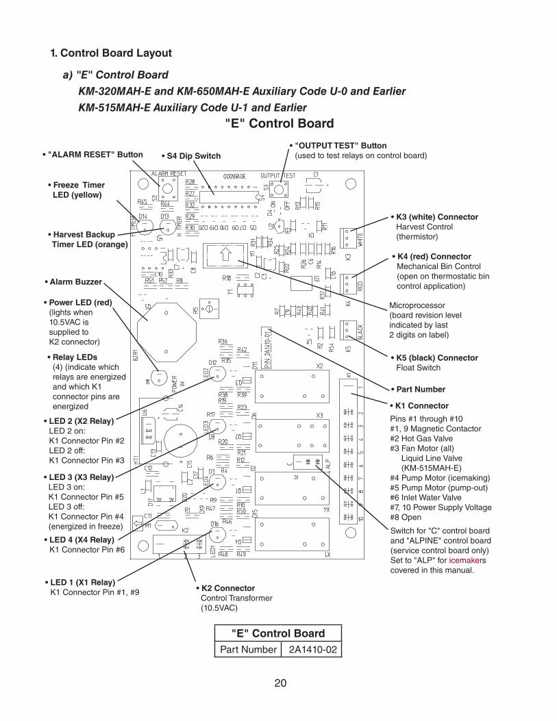
"E" Control BoardPart Number 2A1410-02
"E" Control Board
1. Control Board Layout
a) "E" Control Board
KM-320MAH-E and KM-650MAH-E Auxiliary Code U-0 and Earlier
KM-515MAH-E Auxiliary Code U-1 and Earlier
Microprocessor(board revision level indicated by last 2 digits on label)
• Part Number
• K1 Connector
Pins #1 through #10#1, 9 Magnetic Contactor#2 Hot Gas Valve#3 Fan Motor (all) Liquid Line Valve (KM-515MAH-E)#4 Pump Motor (icemaking)#5 Pump Motor (pump-out)#6 Inlet Water Valve#7, 10 Power Supply Voltage #8 Open
Switch for "C" control board and "ALPINE" control board(service control board only)Set to "ALP" for icemakers covered in this manual.
• Freeze Timer LED (yellow)
• Harvest Backup Timer LED (orange)
• K2 Connector Control Transformer (10.5VAC)
• "ALARM RESET" Button • S4 Dip Switch• "OUTPUT TEST" Button
(used to test relays on control board)
• K3 (white) ConnectorHarvest Control (thermistor)
• K4 (red) Connector Mechanical Bin Control (open on thermostatic bin control application)
• K5 (black) ConnectorFloat Switch
• LED 1 (X1 Relay)K1 Connector Pin #1, #9
• LED 4 (X4 Relay) K1 Connector Pin #6
• LED 3 (X3 Relay) LED 3 on: K1 Connector Pin #5 LED 3 off: K1 Connector Pin #4 (energized in freeze)
• LED 2 (X2 Relay)LED 2 on: K1 Connector Pin #2LED 2 off: K1 Connector Pin #3
• Relay LEDs (4) (indicate which relays are energized and which K1 connector pins are energized
• Power LED (red)(lights when 10.5VAC is supplied to K2 connector)
• Alarm Buzzer
21
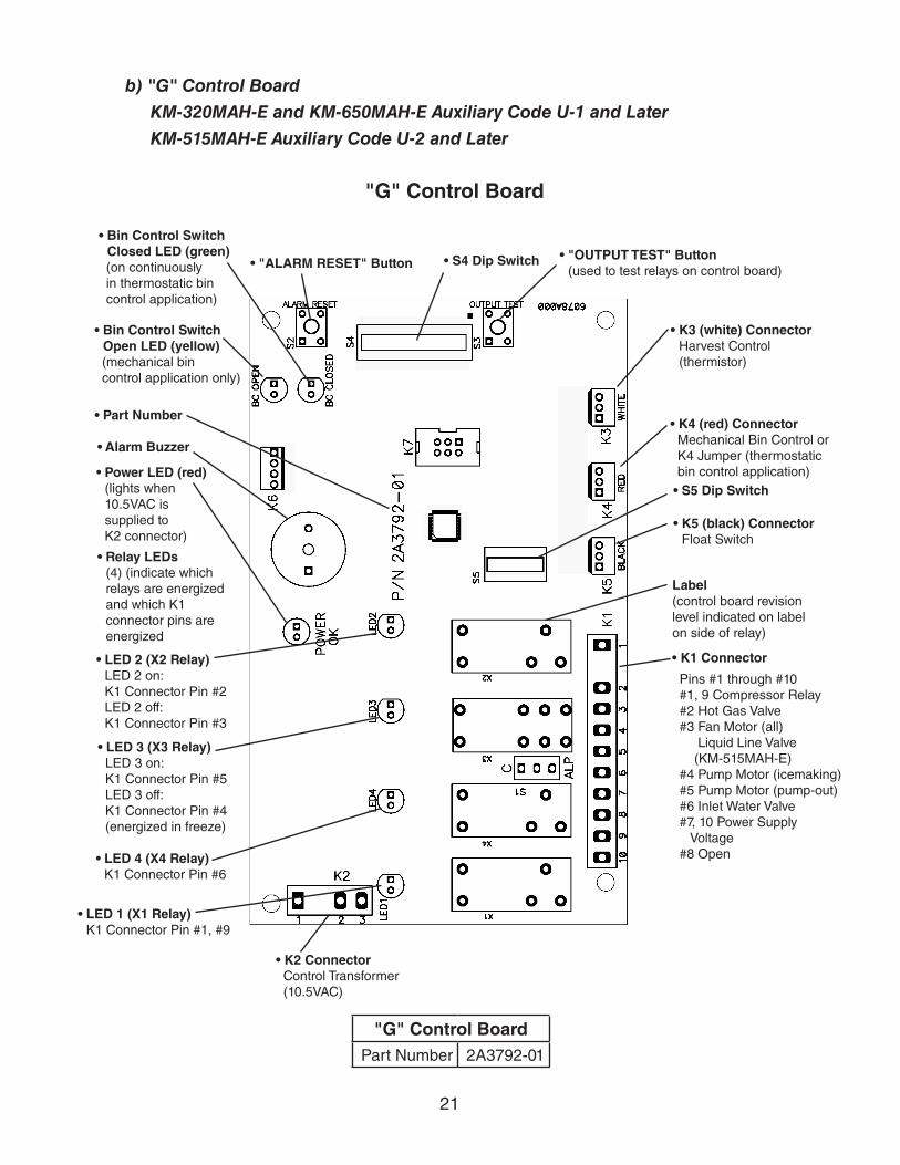
"G" Control BoardPart Number 2A3792-01
"G" Control Board
• K4 (red) Connector Mechanical Bin Control or K4 Jumper (thermostatic bin control application)
Label(control board revision level indicated on label on side of relay)
• K1 Connector
Pins #1 through #10 #1, 9 Compressor Relay #2 Hot Gas Valve #3 Fan Motor (all) Liquid Line Valve (KM-515MAH-E) #4 Pump Motor (icemaking) #5 Pump Motor (pump-out) #6 Inlet Water Valve #7, 10 Power Supply Voltage #8 Open
• Bin Control Switch Open LED (yellow)
(mechanical bin control application only)
• Bin Control Switch Closed LED (green)
(on continuously in thermostatic bin control application)
• LED 2 (X2 Relay)LED 2 on: K1 Connector Pin #2LED 2 off: K1 Connector Pin #3
• LED 3 (X3 Relay) LED 3 on: K1 Connector Pin #5 LED 3 off: K1 Connector Pin #4 (energized in freeze)
b) "G" Control Board
KM-320MAH-E and KM-650MAH-E Auxiliary Code U-1 and Later
KM-515MAH-E Auxiliary Code U-2 and Later
• Power LED (red)(lights when 10.5VAC is supplied to K2 connector)
• LED 4 (X4 Relay) K1 Connector Pin #6
• LED 1 (X1 Relay)K1 Connector Pin #1, #9
• K2 Connector Control Transformer (10.5VAC)
• S5 Dip Switch
• "ALARM RESET" Button • S4 Dip Switch • "OUTPUT TEST" Button(used to test relays on control board)
• K3 (white) ConnectorHarvest Control (thermistor)
• K5 (black) ConnectorFloat Switch
• Part Number
• Alarm Buzzer
• Relay LEDs (4) (indicate which relays are energized and which K1 connector pins are energized

22
2. LED Lights and Audible Alarm Safeties
a) "E" Control Board
KM-320MAH-E and KM-650MAH-E Auxiliary Code U-0 and Earlier
KM-515MAH-E Auxiliary Code U-1 and Earlier
At startup, a 5-second delay occurs while the control board conducts an internal timer check. A beep occurs when power is turned off. The red LED indicates proper control voltage and remains on unless a control voltage problem occurs. The green LEDs 1 through 4 energize and sequence from initial startup as listed in the table below. Note that the order of the LEDs from the outer edge of the control board is 1, 4, 3, 2. For details, see "II.B.1.a) "E" Control Board."
Sequence Step LEDEnergized
ComponentsTime LEDs are On
Min. Max. Avg.1-Minute Fill Cycle 4 WV 1 minuteHarvest Cycle 1, 4, 2 Comp, FMR, HGV, WV 2 minutes 20 minutes 3 to 5 minutesFreeze Cycle 1 Comp, FM/FMR, PM
LLV (KM-515MAH-E)5 minutes freeze timer
setting30 to 35 minutes
Pump-Out Cycle 1, 4*, 3, 2 Comp, FMR, HGV, PM, WV*
10 seconds 20 seconds *pump-out timer setting
The built in safeties shut down the icemaker and have alarms as listed below.
No. of Beeps (every 3 sec.)
Type of Alarm Notes
1 High Evaporator Temp. (temperature > 127°F) (53°C)
Check for harvest problem (stuck HGV or relay), hot water entering icemaker, or shorted thermistor.
2 Harvest Backup Timer (harvest > 20 min. for two cycles in a row)
Orange LED marked H TIMER lights up. Check for open thermistor, HGV not opening, TXV or LLV leaking by, low charge, or inefficient Comp.
3 Freeze Timer (freeze > specified setting for two cycles in a row)
YellowLEDmarkedFTIMERlightsup.CheckforF/Sstuck closed (up), WV leaking by, HGV leaking by, PM not pumping, TXV not feeding properly, LLV not opening, low charge, or inefficient Comp.
To reset the above safeties, press the "ALARM RESET" button with the power supply on.6 Low Voltage
(92Vac±5% or less)Red LED will turn off if voltage protection operates. The control voltage safeties automatically reset when voltage is corrected.7 High Voltage
(147Vac±5% or more)
Legend: Comp–compressor; FM–fan motor; FMR–fan motor remote; F/S–floatswitch;HGV–hot gas valve; LLV–liquid line valve (KM-515MAH-E); PM–pump motor; TXV–thermostatic expansion valve; WV–inlet water valve

23
b) "G" Control Board
KM-320MAH-E and KM-650MAH-E Auxiliary Code U-1 and Later
KM-515MAH-E Auxiliary Code U-2 and Later
At startup, a 5-second delay occurs while the control board conducts an internal timer check. A beep occurs when the control switch is moved to the "ICE" position. The red LED indicates proper control voltage and remains on unless a control voltage problem occurs. The green LEDs 1 through 4 energize and sequence from initial startup as listed in the table below. Note that the order of the LEDs from the outer edge of the control board is 1, 4, 3, 2. For details, see "II.B.1.b) "G" Control Board."
Sequence Step LEDEnergized
ComponentsTime LEDs are On
Min. Max. Avg.1-Minute Fill Cycle 4 WV 1 minuteHarvest Cycle 1, 4, 2 Comp, FMR, HGV, WV 2 minutes 20 minutes 3 to 5 minutesHarvest Pump Timer(not used on these models)
1, 3, 2 Comp, FMR, HGV, PM 0 seconds 50 seconds harvest pump timer setting
Freeze Cycle 1 Comp, FM/FMR, PM,LLV (KM-515MAH-E)
5 minutes freeze timersetting
30 to 35 minutes
Pump-Out Cycle 1, 4*, 3, 2 Comp, FMR, HGV, PM, WV*
10 seconds 20 seconds *pump-out timer setting
The built-in safeties shut down the icemaker and have alarms as listed below.
No. of Beeps (every 3 sec.)
Type of Alarm Notes
1 High Evaporator Temp. (temperature > 127°F) (53°C)
Check for harvest problem (stuck HGV or relay), hot water entering icemaker, or shorted thermistor.
2 Harvest Backup Timer (harvest > 20 min. for two cycles in a row)
Check for open thermistor, HGV not opening, TXV or LLV leaking by, low charge, or inefficient Comp.
3 Freeze Timer (freeze > freeze timer setting for two cycles in a row)
Check for F/S stuck closed (up), WV leaking by, HGV leaking by, PM not pumping, TXV not feeding properly, LLV not opening, low charge, or inefficient Comp.
To reset the above safeties, press the "ALARM RESET" button with the power supply on.6 Low Voltage
(92Vac±5% or less)Red LED turns off if voltage protection operates. The control voltage safeties automatically reset when voltage is corrected.7 High Voltage
(147Vac±5% or more)
Legend: Comp–compressor; FM–fan motor; FMR–fan motor remote; F/S–floatswitch;HGV–hot gas valve; LLV–liquid line valve (KM-515MAH-E); PM–pump motor; TXV–thermostatic expansion valve; WV–inlet water valve

24
3. Controls and Adjustments
NOTICEDip switches are factory set. Failure to maintain factory settings may adversely affect performance and warranty coverage. For more information, contact your Hoshizaki Service Center.
a) Default Dip Switch SettingsThe dip switches are factory-adjusted to the following positions for both the "E" and "G" control boards:
S4 Dip Switch No. 1 2 3 4 5 6 7 8 9 10
KM-320MAH-E ON OFF OFF ON ON ON OFF OFF ON ON
KM-515MAH-E OFF OFF OFF OFF OFF OFF OFF OFF ON OFF
KM-650MAH-E OFF OFF OFF OFF OFF OFF OFF OFF ON ON
S5 Dip Switch (Do Not Adjust)"G" Control Board
Dip Switch No. 1 2 3 4 5
KM-320MAH-EKM-515MAH-EKM-650MAH-E
OFF OFF OFF OFF OFF
Freeze Timer (9 & 10)
Pump-Out Frequency Control (5 & 6)
Pump-Out Timer (3 & 4)
Harvest Timer (1 & 2)
Factory Use (8)
Bin Control Selector (7) "E" Control BoardHarvest Pump Timer (7) "G" Control Board(Do Not Adjust)
12
34
56
78
910
ON
S4 Dip Switch "E" and "G" Control Boards
12
34
5
ON
Do Not Adjust
S5 Dip Switch "G" Control Board Only
Refill Counter (2 through 5)
Float Switch Selector (1)

25
b) Harvest Timer (S4 dip switch 1 & 2)The harvest timer starts counting when the thermistor reaches 48°F (9°C) at the evaporator outlet and the control board reads 3.9 kΩ from the thermistor. The harvest timer is factory set, and generally no adjustment is required. However, a setting longer thanthefactorysettingmaybeadvisedincaseswheretheflushprovidedatharvestneeds to be prolonged for extra cleaning. Before changing this setting, contact your Hoshizaki Service Office for recommendations. Keep in mind that setting the harvest timer to a longer setting decreases 24-hour production.Note that the pump-out timer (S4 dip switch 3 & 4) acts in place of the harvest timer during cycles with a pump out. For details, see "II.C.3.c) Pump-Out Timer (S4 dip switch 3 & 4)." On KM-515MAH-E and KM-650MAH-E models, the harvest timer is only relevant during the initial harvest cycle since a pump out occurs every cycle thereafter.
S4 Dip Switch Setting Time (seconds)No. 1 No. 2
OFF OFF 60
ON OFF 90
OFF ON 120
ON ON 180
c) Pump-Out Timer (S4 dip switch 3 & 4)
NOTICEOn KM-515MAH-E and KM-650MAH-E models, never adjust the pump-out timer's harvest timer (T2) for a time less than 150 seconds. Otherwise, the icemaker will not perform properly.
When a pump-out is called for, the pump motor de-energizes after the preceding freeze cycle. The pump motor energizes 2 seconds later in the reverse direction, taking water from the bottom of the water tank and forcing pressure against the check valve seat allowing water to go through the check valve and down the drain. At the same time, water flowsthroughthesmalltubetopowerflushthefloatswitch.Thepumpmotordrainsthewater tank for the time determined by the pump-out timer. The pump-out timer also acts in place of the harvest timer during cycles with a pump-out. The pump-out timer is factory set, and generally no adjustment is required. However, where water quality is bad and the icemaker needs a longer pump-out time, the pump-out timer can be adjusted. The pump-out timer control can be set to pump-out for 10 or 20 seconds.
S4 Dip Switch Setting Time (seconds) Inlet Water ValveNo. 3 No. 4 T1 T2
OFF OFF 10 150 Closed
ON OFF 10 180 Closed
OFF ON 10 120 Open
ON ON 20 180 Closed
T1: Time to drain the water tankT2: Harvest timer at pump out

26
d) Pump-Out Frequency Control (S4 dip switch 5 & 6)
NOTICEOn KM-515MAH-E and KM-650MAH-E models: Do not adjust. Adjustments to this setting may adversely affect performance and warranty coverage.
The pump-out frequency control is factory set to drain the water tank every 10 cycles on the KM-320MAH-E and every cycle on the KM-515MAH-E and the KM-650MAH-E, and generally no adjustment is required. However, where water quality is bad and the icemaker needs a pump-out more often, the pump-out frequency can be adjusted. The pump-out frequency control can be set to have a pump-out occur every cycle, or every 2, 5, or 10 cycles.
Timing of the first pump-out is dependent on the control board. "E" control board first pump-out is after the first freeze cycle. "G" control board first pump-out is dependent on S4 dip switch 5 & 6. See the table below.
"E" & "G" Control Board 1st Pump-Out
S4 Dip Switch Setting Pump-Out Frequency
"E" Control Board "G" Control BoardNo. 5 No. 6
OFF OFF Every cycle After 1st freeze cycle After 2nd freeze cycle
ON OFF Every 2 cycles After 3rd freeze cycle
OFF ON Every 5 cycles After 6th freeze cycle
ON ON Every 10 cycles After 11th freeze cycle
e) Bin Control Selector/Harvest Pump Timer (S4 dip switch 7)Depending on the control board, S4 dip switch 7 is either a bin control selector or harvest pump timer.
NOTICEDo not adjust. This dip switch must be left in the factory default position or this icemaker will not operate correctly.
(1) Bin Control Selector, "E" Control Board
KM-320MAH-E and KM-650MAH-E Auxiliary Code U-0 and Earlier
KM-515MAH-E Auxiliary Code U-1 and Earlier
Factory set for proper operation. Do not adjust. When set to the on position on a icemaker with a thermostatic bin control, a 5-beep alarm sounds (open circuit) and the icemaker does not operate.
"E" Control Board
S4 Dip Switch SettingBin Control
No. 7
ON Mechanical
OFF Thermostatic

27
(2) Harvest Pump Timer, "G" Control Board
KM-320MAH-E and KM-650MAH-E Auxiliary Code U-1 and Later
KM-515MAH-E Auxiliary Code U-2 and Later
Factory set for proper operation. Do not adjust. Depending on the harvest pump timer setting, the pump motor energizes and runs the last 0 or 50 seconds of harvest. The water valve is energized during harvest for a maximum of 6 minutes or the length of harvest minus 0 or 50 seconds (determined by the harvest pump timer setting), whichever is shorter. NOTICE! Do not adjust S4 dip switch 7 out of the factory default position on this model. This dip switch must be left in the factory default position or this icemaker will not operate correctly.
"G" Control Board
S4 Dip Switch Setting Pump Motor Time (seconds)No. 7
ON 50
OFF 0
f) Factory Use (S4 dip switch 8)Factory set for proper operation. Do not adjust. This must be left in the factory default position.
g) Freeze Timer (S4 dip switch 9 & 10)
NOTICEAdjust to proper specification, or the icemaker may not operate correctly.
The freeze timer setting determines the maximum allowed freeze time to prevent possible freeze-up issues. Upon termination of the freeze timer, the control board initiates the harvest cycle. After 2 consecutive timer terminations, the control board shuts the icemaker down. In this case, see "IV.F.3. Low Ice Production" for possible solutions.The freeze timer is factory set and no adjustment is required.
S4 Dip Switch Setting Time (minutes)No. 9 No. 10
OFF OFF 60
OFF ON 50
ON OFF 70
ON ON 75

28
h) Float Switch Selector (S5 dip switch 1): "G" Control Board
NOTICEDo not adjust. This must be left in the factory default position or the icemaker will not operate correctly.
i) Refill Counter (S5 dip switch 2 through 5): "G" Control Board
NOTICEDo not adjust. These must be left in the factory default position or the icemaker will not operate correctly.
D. Control SwitchThe control switch has three positions: "OFF" for power off, "ICE" for icemaking, and"WASH" to activate the water pump when cleaning and sanitizing.

29
III. Technical Information
A. Water Circuit and Refrigeration Circuit
1. KM-320MAH-E, KM-515MAH-E, and KM-650MAH-E
Water Supply
Float Switch
Drain
Check Valve
Thermostatic Expansion Valve
Compressor
Hot Gas Valve
High-Pressure Switch
Strainer
Fan
Drier
Condenser
Evaporator
Discharge Line
Suction Line
Water Pump
Thermistor
Spray Tubes
Inlet Water Valve
Freeze Pump Out
Water Tank
Refrigeration Circuit
Water Circuit
Heat Exchanger
Liquid Line Valve (KM-515MAH-E)
30
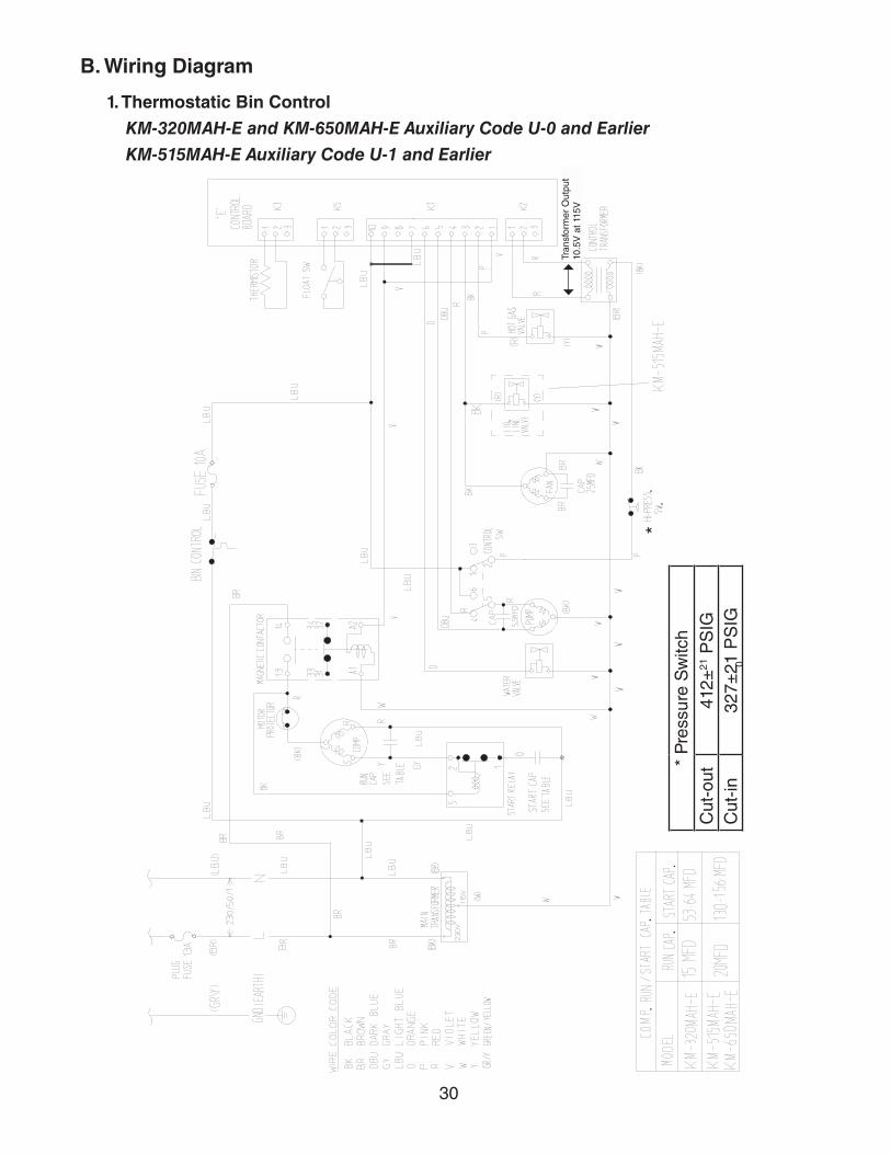
B. Wiring Diagram
1. Thermostatic Bin Control
KM-320MAH-E and KM-650MAH-E Auxiliary Code U-0 and Earlier
KM-515MAH-E Auxiliary Code U-1 and Earlier
Tran
sfor
mer
Out
put
10.5
V a
t 115
V
**
Pre
ssur
e S
witc
hC
ut-o
ut41
2±21
PS
IG
Cut
-in32
7±21
PS
IG0

31
2. Mechanical Bin Control
KM-320MAH-E and KM-650MAH-E Auxiliary Code U-1 and Later
KM-515MAH-E Auxiliary Code U-2 and Later
Tran
sfor
mer
Out
put
10.5
V a
t 115
V
*
* P
ress
ure
Sw
itch
Cut
-out
412±
21 P
SIG
C
ut-in
327±
21 P
SIG
0

32
C. Performance Data
1. KM-320MAH-E
Note:1. Pressure data is recorded at 5 minutes into freezing cycle. The data not in bold
should be used for reference only.2. We reserve the right to make changes in specifications and design without prior
notice.
70/21 293 133 275 125 255 11680/27 279 127 252 114 234 10690/32 275 125 232 105 213 97
lbs./day kg./day 100/38 273 124 228 103 196 8970/2180/2790/32
watts 100/3870/21 117 0.44 98 0.37 89 0.3480/27 103 0.39 73 0.28 73 0.2890/32 98 0.37 52 0.19 47 0.18
gal./day m3/day 100/38 76 0.29 51 0.19 43 0.1670/2180/2790/32
min. 100/3870/2180/2790/32
min. 100/3870/21 210 14.8 235 16.5 253 17.880/27 229 16.1 268 18.8 276 19.490/32 235 16.5 295 20.7 308 21.7
PSIG kg/cm2G 100/38 233 16.4 298 21.0 320 22.570/21 56 3.9 57 4.0 58 4.180/27 57 4.0 59 4.1 60 4.290/32 57 4.0 60 4.2 61 4.3
PSIG kg/cm2G 100/38 57 4.0 60 4.2 62 4.4
5,400 BTU/h [AT 90ºF (32ºC) / WT 70ºF (21ºC)]
36
473737
47
3742
2.8
5.8
3.9
4.93.82.8
5.1
34
APPROXIMATE ICE PRODUCTION PER 24 HR.
APPROXIMATE ELECTRIC CONSUMPTION
APPROXIMATE WATER CONSUMPTION PER 24 HR.
FREEZING CYCLE TIME
WATER TEMP. (ºF/ºC)AMBIENT TEMP. (ºF/ºC) 50/10 70/21 90/32
663
668691710710
650663668
39424748
673686710710
HARVEST CYCLE TIME
HEAD PRESSURE
4.53.8
4.9 2.72.5
TOTAL HEAT OF REJECTION FROM CONDENSER
SUCTION PRESSURE

33
2. KM-515MAH-E
Note:1. Pressure data is recorded at 5 minutes into freezing cycle. The data not in bold
should be used for reference only.2. We reserve the right to make changes in specifications and design without prior
notice.
70/21 513 233 482 219 441 20080/27 490 222 442 200 401 18290/32 482 219 408 185 366 166
lbs./day kg./day 100/38 474 215 398 181 328 14970/2180/2790/32
watts 100/3870/21 159 0.60 144 0.55 131 0.5080/27 148 0.56 125 0.47 115 0.4490/32 144 0.55 108 0.41 97 0.37
gal./day m3/day 100/38 125 0.47 106 0.40 87 0.3370/2180/2790/32
min. 100/3870/2180/2790/32
min. 100/3870/21 245 17.2 267 18.8 294 20.680/27 262 18.4 296 20.8 321 22.590/32 267 18.8 320 22.5 346 24.3
PSIG kg/cm2G 100/38 271 19.1 326 22.9 370 26.070/21 50 3.5 54 3.8 57 4.080/27 53 3.8 60 4.2 61 4.390/32 54 3.8 65 4.6 67 4.7
PSIG kg/cm2G 100/38 54 3.8 65 4.6 69 4.9
10,400 BTU/h [AT 90ºF (32ºC) / WT 70ºF (21ºC)]
28
342829
33
3.02.9
3.3
26
APPROXIMATE WATER CONSUMPTION PER 24 HR.
FREEZING CYCLE TIME
WATER TEMP. (ºF/ºC)AMBIENT TEMP. (ºF/ºC) 50/10 70/21 90/32
1118
2831
108011071115
APPROXIMATE ICE PRODUCTION PER 24 HR.
APPROXIMATE ELECTRIC CONSUMPTION
1115116112001207
1150118912311260
32353740
HARVEST CYCLE TIME
HEAD PRESSURE
3.23.1
3.2 2.92.9
3.4
3.1
3.2
2.9
TOTAL HEAT OF REJECTION FROM CONDENSER
SUCTION PRESSURE
34
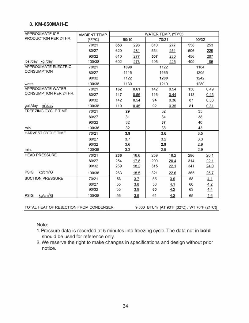
3. KM-650MAH-E
Note:1. Pressure data is recorded at 5 minutes into freezing cycle. The data not in bold
should be used for reference only.2. We reserve the right to make changes in specifications and design without prior
notice.
70/21 653 296 610 277 558 25380/27 620 281 554 251 506 22990/32 610 277 507 230 456 207
lbs./day kg./day 100/38 602 273 495 225 409 18670/2180/2790/32
watts 100/3870/21 162 0.61 142 0.54 130 0.4980/27 147 0.56 116 0.44 113 0.4390/32 142 0.54 94 0.36 87 0.33
gal./day m3/day 100/38 119 0.45 92 0.35 81 0.3170/2180/2790/32
min. 100/3870/2180/2790/32
min. 100/3870/21 236 16.6 259 18.2 286 20.180/27 254 17.8 290 20.4 314 22.190/32 259 18.2 315 22.1 341 24.0
PSIG kg/cm2G 100/38 263 18.5 321 22.6 365 25.770/21 53 3.7 55 3.9 58 4.180/27 55 3.8 58 4.1 60 4.290/32 55 3.9 60 4.2 63 4.4
PSIG kg/cm2G 100/38 56 3.9 61 4.3 65 4.6
9,800 BTU/h [AT 90ºF (32ºC) / WT 70ºF (21ºC)]
2.9
TOTAL HEAT OF REJECTION FROM CONDENSER
SUCTION PRESSURE
HARVEST CYCLE TIME
HEAD PRESSURE
3.53.3
3.6 2.9
1164120512421280
35384043
1130
1122116512001210
109011151122
WATER TEMP. (ºF/ºC)AMBIENT TEMP. (ºF/ºC) 50/10 70/21 90/32
APPROXIMATE ICE PRODUCTION PER 24 HR.
APPROXIMATE ELECTRIC CONSUMPTION
APPROXIMATE WATER CONSUMPTION PER 24 HR.
FREEZING CYCLE TIME 3234
2.9
3.9
3.3
3.63.22.9
3.7
2931
383232
37

35
IV. Service Diagnosis
WARNING•Thisicemakershouldbediagnosedandrepairedonlybyqualifiedservice
personnel to reduce the risk of death, electric shock, serious injury, or fire.
•Riskofelectricshock.Useextremecautionandexercisesafeelectricalpractices.
•Movingparts(e.g.,fanblade)cancrushandcut.Keephandsclear.
•CHOKING HAZARD: Ensure all components, fasteners, and thumbscrews are securely in place after the icemaker is serviced. Make sure that none have fallen into the dispenser icemaker/storage bin.
•Makesureallfoodzonesintheicemakeranddispensericemaker/storagebinareclean after service. For cleaning procedures, see "VI. Cleaning and Maintenance."
A. Diagnostic ProcedureThe diagnostic procedure is basically a sequence check which can be used at icemaker startup or for system diagnosis. This procedure allows you to diagnose electrical system and component failures. Before conducting the diagnostic procedure, check for correct installation, proper voltage per icemaker nameplate, and adequate water supply. Check CB using the steps in "IV.B. Control Board Check." Check the dip switch settings to assure that S4 dip switch 3, 4, 7, 8, 9, 10 and S5 dip switch 1 through 5 ("G" CB) are in the factory default position. S4 dip switch 1, 2, 5, 6 are cleaning adjustments and thesettingsareflexible.Forfactorydefaultsettings,see"II.C.3.a)DefaultDipSwitchSettings." As you go through the procedure, check to assure the components energize and de-energize correctly. If not, those components and controls are suspect.
1) Remove the front panel. Move the control switch to the "OFF" position, then unplug the icemaker from the mains socket. Clear any ice from TBC or MBC.
2) Plug the icemaker back into the mains socket, then move the control switch to the "ICE" position. A 5-second delay occurs. The red "POWER OK" LED on CB comes on. On "G" CB, the green "BC CLOSED" LED also comes on. If the yellow "BC OPEN" LED is on (indicating a full bin), check MBC. See "IV.C.2.a) Mechanical Bin Control Check." If CB LEDs do not turn on, see "IV.F.1. No Ice Production."
3) 1-Minute Fill Cycle – LED 4 is on. WV energizes. After 1 minute, CB checks for a closed F/S. If F/S is closed, the harvest cycle begins. If closed, continue to step 4. If F/S is open, WV remains energized through additional 1-minute fill cycles until water enters the water tank and F/S closes (low water safety protection during initial start up and at the end of each harvest). Diagnosis: Confirm that water enters the water tank. If not, check that the water supply shut-off valve is open and screens or external filters are clear. Check supply voltage at WV solenoid. If no voltage is present, see "IV.B. Control Board Check." If voltage is present, check solenoid continuity. If the water tank fills, but the icemaker fails to start harvest, check for open F/S. See "IV.D. 1. Float Switch Check." If F/S checks ok, replace CB.
36
4) Initial Harvest Cycle – LEDs 1, 4, and 2 are on. WV remains energized, Comp and HGV energize. CB monitors the warming of the evaporator via the thermistor located on the suction line. When the thermistor reaches 48°F (9°C), CB reads 3.9 kΩ from the thermistor and turns harvest termination over to the harvest timer (S4 dip switch 1 & 2). The harvest timer has settings of 60, 90, 120, and 180 seconds. When the harvest timer terminates, the harvest cycle is complete. CB checks the position of F/S and proceeds to the next cycle if it is closed or calls for a 1-minute fill cycle if it is open. The minimum total time allowed by CB for a complete harvest cycle is 2 minutes.
The pump-out timer (S4 dip switch 3 & 4) acts in place of the harvest timer during cycles with a pump-out (S4 dip switch 5 & 6). WV is energized during harvest for a maximum of 6 minutes. NOTICE! Do not adjust S4 dip switch 7 out of the factory default position on this model. This dip switch must be left in the factory default position or this icemaker will not operate correctly. For details, see "II.C.3.e) Bin Control Selector/Harvest Pump Timer (S4 Dip Switch 7)."
Diagnosis: Check if Comp is running, HGV and WV still energized. Average harvest cycle at factory setting is 2 to 3 minutes. How long does initial harvest last? 1.5 minutes after initial harvest begins, touch Comp discharge line. Is it hot? If not, check refrigerant pressures and Comp operation. If it is hot, touch the inlet line to the evaporator. Is it hot? If it is hot and the freeze cycle is not starting, check the harvest timer adjustment (S4 dip switch 1 & 2), the thermistor for open circuit, the discharge line temperature, Comp efficiency, and if HGV is fully open. For a thermistor check, see "IV.E. Thermistor Check." If 1-minute fill cycle starts after harvest, check that F/S is clean and operating properly, see "IV.D. Float Switch Check and Cleaning." Make sure PM does not come on last 50 seconds of harvest on icemakers with "G" CB. For details, see "II.C.3.e) Bin Control Selector/Harvest Pump Timer (S4 Dip Switch 7)."

37
5) Freeze Cycle – LED 1 is on. Comp remains energized, PM, FM, and LLV (KM-515MAH-E) energize. WV and HGV de-energize. For the first 5 minutes, CB will not terminate the freeze cycle. At the end of 5 minutes, F/S assumes control of the freeze cycle. As ice builds on the evaporator, the water level in the water tank lowers. Freeze continues until F/S opens, provided the 5-minute minimum freeze timer has terminated. Diagnosis: During the first 5 minutes of freeze, confirm that the evaporator temperature drops. If the evaporator is not cold, check to see if HGV is still open or if TXV is not opening properly, if WV is continuing to fill the reservoir, if there are improper icemaker pressures, or an inoperative Comp. After 5 minutes in freeze, disconnect black F/S connector from CB BLACK K5 connector. The icemaker should switch out of the freeze cycle ("G" CB - 15 second delay after F/S opens before terminating the freeze cycle). If the icemaker switches out of freeze with F/S removed, but would previously not switch out of freeze with F/S connected (long freeze - 3 beep alarm), F/S may be sticking. To check and clean F/S, see "IV.D. Float Switch Check and Cleaning." If the icemaker remains in freeze (longer than 15 seconds on "G" CB) after disconnecting the black F/S connector, replace CB. Note: Normal freeze cycle will last 20 to 40 minutes depending on model and
conditions. Cycle times and pressures should follow performance data provided in this manual. See "III.C. Performance Data."
6) Pump-Out Cycle – (10/20 second pump-out) – LEDs 1, 3, and 2 are on. LED 4 is on when S4 dip switch 3 & 4 are set to 3 off and 4 on (KM-320MAH-E). Comp remains energized, HGV energizes. WV energizes if S4 dip switch 3 off and 4 on. LLV (KM-515MAH-E) and FM de-energize. PM stops for 2 seconds, then reverses for 10/20 seconds depending on pump-out timer S4 dip switch 3 & 4 setting. When the pump-out timer expires, the pump-out is complete. The pump-out frequency control is factory set for every 10th cycle on KM-320MAH-E and every cycle for KM-515MAH-E and KM-650MAH-E. Generally no adjustment is required. However, the pump-out frequency can be adjusted. The pump-out frequency control (S4 dip switch 5 & 6) can be set to have a pump-out occur every cycle, or every 2, 5, or 10 cycles. For details, see "II.C.3.d) Pump-Out Frequency Control (S4 dip switch 5 & 6)."
Timing of the first pump-out is dependent on CB. "E" CB first pump-out is after the first freeze cycle. "G" CB first pump-out is determined by S4 dip switch 5 & 6. See the table below.
"E" & "G" Control Board Settings 1st Pump-Out
S4 Dip Switch Setting Pump-Out Frequency
"E" Control Board "G" Control BoardNo. 5 No. 6
OFF OFF Every cycle After 1st freeze cycle After 2nd freeze cycle
ON OFF Every 2 cycles After 3rd freeze cycle
OFF ON Every 5 cycles After 6th freeze cycle
ON ON Every 10 cycles After 11th freeze cycle
Diagnosis: Check PM circuit and capacitor, check #5 pin (DBU wire) on CB K1 ten-pin connector for voltage. If water does not pump out, check and clean the check valve assembly and tubing.

38
7) Normal Harvest Cycle – same as the initial harvest cycle – See "IV.A.4) Initial Harvest Cycle."
8) Shutdown
a) Thermostatic Bin Control:
KM-320MAH-E and KM-650MAH-E Auxiliary Code U-0 and Earlier
KM-515MAH-E Auxiliary Code U-1 and Earlier
When the icemaker is running hold ice in contact with the thermostatic bulb, TBC switch opens within 10 seconds, shutting down the icemaker. TBC is factory set, and generally no adjustment is required. However, adjustment may be needed in some conditions, particularly at higher altitude locations. NOTICE! Do not adjust S4 dip switch 7 out of the factory default position on this model. This dip switch must be left in the factory default position or this icemaker will not operate correctly. Diagnosis: See "IV.C.1. Thermostatic Bin Control Check: Auxiliary Code U-0 and Earlier."
b) Mechanical Bin Control:
KM-320MAH-E and KM-650MAH-E Auxiliary Code U-1 and Later
KM-515MAH-E Auxiliary Code U-2 and Later
See "IV.C.2.a) Mechanical Bin Control Check."
Legend: CB–control board; Comp–compressor; FM–fan motor; F/S–floatswitch;HGV–hot gas valve; LLV–liquid line valve (KM-515MAH-E); MBC–mechanical bin control; PM–pump motor; TBC–thermostatic bin control; TXV–thermostatic expansion valve; WV–inlet water valve

39
B. Control Board CheckBefore replacing CB that does not show a visible defect and that you suspect is bad, always conduct the following check procedure. This procedure will help you verify your diagnosis.
Alarm Reset: If CB is in alarm (beeping), press the "ALARM RESET" button on CB while CB is beeping. WARNING! Risk of electric shock. Care should be taken not to touch live terminals. Once reset, the icemaker starts at the 1-minute fill cycle. For audible alarm information, see "II.C.2. LED Lights and Audible Alarm Safeties."
1) Check the dip switch settings to assure that S4 dip switch 3, 4, 7, 8, 9, 10 and S5 dip switch 1 through 5 ("G" CB) are in the factory default position. S4 dip switch 1, 2, 5, 6 arecleaningadjustmentsandthesettingsareflexible.Forfactorydefaultsettings,see"II.C.3.a) Default Dip Switch Settings."
2) Move the control switch to the "ICE" position. If the red "POWER OK" LED is on, control voltage is good, continue to step 3. If the "POWER OK" LED is off, check CT secondary circuit. CT output is 10.5VAC at 115VAC primary input. If the secondary circuit has proper voltage and the red LED is off, replace CB.
If the secondary circuit does not have proper voltage, check CT primary circuit. Check for 115VAC at CB K1 connector pin #10 (BR wire) to a neutral (W wire) for 115VAC. (Always choose a neutral (W wire) to establish a good neutral connection when checking voltages.) For additional checks, see "IV.F.1. No Ice Production."
3) The "OUTPUT TEST" button provides a relay sequence test. Make sure the control switch is in the "ICE" position, then press the "OUTPUT TEST" button. For the correct lighting sequence, see the table below. Note that the order of the LEDs from the outer edge of the control board is 1, 4, 3, 2. Components (e.g., compressor) cycle during the test.
Control Board
Correct LED Lighting Sequence
"E" 2, 3, 4, 1
"G" 1, 4, 3, 2
Following the test, the icemaker begins operation at the 1-minute fill cycle. If the LEDs do not light as described above, replace CB.
4) To verify voltage output from CB to the components, slide the CB K1 connector out far enough to allow multimeter lead contact. With the icemaker in the cycle to be tested, check output voltage from the corresponding pin on CB K1 connector to a neutral (W wire). If output voltage is not found and the appropriate LED is on, replace CB.
Legend: CB–control board; CT–control transformer

40
C. Bin Control Check
1. Thermostatic Bin Control Check
KM-320MAH-E and KM-650MAH-E Auxiliary Code U-0 and Earlier
KM-515MAH-E Auxiliary Code U-1 and Earlier
TBC switch is a temperature controlled switch used to control the level of ice in the bin. It is in line with the power supply to the control switch. TBC shuts down the icemaker within 10 seconds when ice contacts the thermostatic bulb, regardless of the cycle at activation. TBC is factory set, and generally no adjustment is required. However, adjustment may be needed in some conditions, particularly at higher altitude locations. To check TBC, follow the steps below.
NOTICEWhen the ambient temperature is below 45°F (7°C), the thermostatic bin control switch opens and shuts down the icemaker even if the ice storage bin is empty. When the thermostat is set in the prohibited range, the icemaker operates continuously even if the ice storage bin is filled with ice. Setting in the prohibited range may result in severe damage to the icemaker.
1) Remove the front panel. Move the control switch to the "OFF" position, then unplug the icemaker from the mains socket.
2) Remove the control box cover.
3) Disconnect TBC wires from TBC switch.
4) Clear any ice away from TBC bulb, then hold your hand around TBC bulb to warm it up.
5) Check for continuity across TBC switch. If closed, continue to step 6. If open, adjust or replace TBC.
6) With the multimeter test leads still in place, hold ice on TBC bulb to lower the temperature. Within 10 seconds, TBC switch should open. If it remains closed, adjust or replace TBC.
Legend: TBC–thermostatic bin control

41
2. Mechanical Bin Control Check and Cleaning
KM-320MAH-E and KM-650MAH-E Auxiliary Code U-1 and Later
KM-515MAH-E Auxiliary Code U-2 and Later
a) Mechanical Bin Control CheckThis icemaker uses a MBC with a lever-actuated proximity switch to control the ice level in the storage bin. No adjustment is required. MBC connects to CB K4 (red) connector. When the actuator paddle is not engaged (MBC closed; CB green "BC CLOSED" LED is on), icemaker produces ice. When the actuator paddle is engaged (MBC open; CB yellow "BC OPEN" LED is on), icemaker shuts down as outlined in the chart below. To check the mechanical bin control switch, follow the steps below.
1) Remove the front panel. Move the control switch to the "OFF" position, then unplug the icemaker from the mains socket.
2) Remove the control box cover, then clear any ice away from MBC.
3) Check MBC wire harness (white) connection. See Fig. 1.
4) Disconnect MBC connector from CB K4 (red) connector.
5) Check for continuity across the wires of MBC connector. When the actuator paddle is not engaged, MBC switch is closed. If open, check that the white harness (white) connector properly connected and that the actuator paddle is not sticking. Clean if necessary. See "IV.C.2.b) Mechanical Bin Control Cleaning." If MBC switch still reads open, replace MBC.
6) Press and hold the actuator paddle; check for continuity across the wires of MBC connector. When the actuator paddle is engaged, MBC switch is open. If closed, check that the actuator paddle is not restricted. Clean if necessary. See "IV.C.2.b) Mechanical Bin Control Cleaning." If MBC switch still reads closed, replace MBC.
7) Reconnect MBC connector to CB K4 (red) connector.
8) Plug the icemaker back into the mains socket, then move the control switch to the "ICE" position to start the automatic icemaking process.
9) Check that the green "BC CLOSED" LED on the control board is on.
10) Allow the icemaker to cycle on. Press and hold the actuator paddle. The yellow "BC OPEN" LED should be on and the icemaker should shut down according to the chart below. If it does not, replace CB.
Cycle at Mechanical Bin Control Activation
Shutdown
Fill Cycle 15 seconds after activation.
Harvest Cycle At the end of the harvest cycle, or up to 15 seconds into the freeze cycle if activated at the end of the harvest cycle.
Freeze Cycle 15 seconds after activation if activated at least 15 seconds before the 5-minute short cycle protection timer terminates. Otherwise, at the end of the next harvest cycle.
Legend: MBC–mechanical bin control; CB–control board;
Actuator Paddle
MBC
MBC Connector (to control board K4 (red) connector)
MBC Wire Harness (white) Connector
Fig. 1
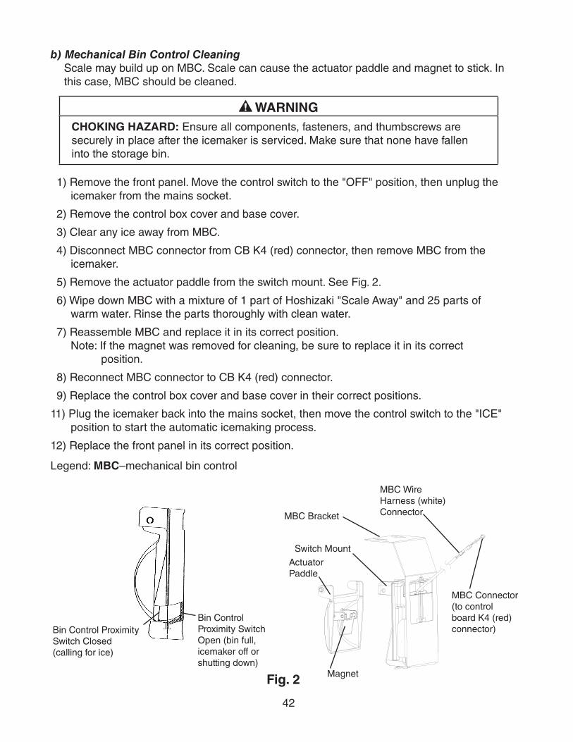
42
b) Mechanical Bin Control CleaningScale may build up on MBC. Scale can cause the actuator paddle and magnet to stick. In this case, MBC should be cleaned.
WARNINGCHOKING HAZARD: Ensure all components, fasteners, and thumbscrews are securely in place after the icemaker is serviced. Make sure that none have fallen into the storage bin.
1) Remove the front panel. Move the control switch to the "OFF" position, then unplug the icemaker from the mains socket.
2) Remove the control box cover and base cover.
3) Clear any ice away from MBC.
4) Disconnect MBC connector from CB K4 (red) connector, then remove MBC from the icemaker.
5) Remove the actuator paddle from the switch mount. See Fig. 2.
6) Wipe down MBC with a mixture of 1 part of Hoshizaki "Scale Away" and 25 parts of warm water. Rinse the parts thoroughly with clean water.
7) Reassemble MBC and replace it in its correct position.Note: If the magnet was removed for cleaning, be sure to replace it in its correct
position.
8) Reconnect MBC connector to CB K4 (red) connector.
9) Replace the control box cover and base cover in their correct positions.
11) Plug the icemaker back into the mains socket, then move the control switch to the "ICE" position to start the automatic icemaking process.
12) Replace the front panel in its correct position.
Legend: MBC–mechanical bin control
MBC Bracket
Magnet
Actuator Paddle
Switch Mount
Fig. 2
Bin Control Proximity Switch Closed(calling for ice)
Bin Control Proximity Switch Open (bin full, icemaker off or shutting down)
MBC Connector (to control board K4 (red) connector)
MBC Wire Harness (white) Connector
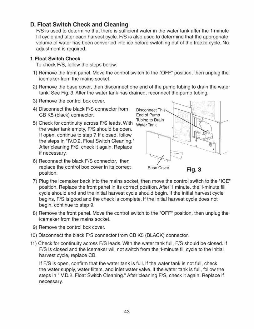
43
D. Float Switch Check and CleaningF/S is used to determine that there is sufficient water in the water tank after the 1-minute fill cycle and after each harvest cycle. F/S is also used to determine that the appropriate volume of water has been converted into ice before switching out of the freeze cycle. No adjustment is required.
1. Float Switch CheckTo check F/S, follow the steps below.
1) Remove the front panel. Move the control switch to the "OFF" position, then unplug the icemaker from the mains socket.
2) Remove the base cover, then disconnect one end of the pump tubing to drain the water tank. See Fig. 3. After the water tank has drained, reconnect the pump tubing.
3) Remove the control box cover.
4) Disconnect the black F/S connector from CB K5 (black) connector.
5) Check for continuity across F/S leads. With the water tank empty, F/S should be open. If open, continue to step 7. If closed, follow the steps in "IV.D.2. Float Switch Cleaning." After cleaning F/S, check it again. Replace if necessary.
6) Reconnect the black F/S connector, then replace the control box cover in its correct position.
7) Plug the icemaker back into the mains socket, then move the control switch to the "ICE" position. Replace the front panel in its correct position. After 1 minute, the 1-minute fill cycle should end and the initial harvest cycle should begin. If the initial harvest cycle begins, F/S is good and the check is complete. If the initial harvest cycle does not begin, continue to step 9.
8) Remove the front panel. Move the control switch to the "OFF" position, then unplug the icemaker from the mains socket.
9) Remove the control box cover.
10) Disconnect the black F/S connector from CB K5 (BLACK) connector.
11) Check for continuity across F/S leads. With the water tank full, F/S should be closed. If F/S is closed and the icemaker will not switch from the 1-minute fill cycle to the initial harvest cycle, replace CB.
If F/S is open, confirm that the water tank is full. If the water tank is not full, check the water supply, water filters, and inlet water valve. If the water tank is full, follow the steps in "IV.D.2. Float Switch Cleaning." After cleaning F/S, check it again. Replace if necessary.
Disconnect This End of Pump Tubing to Drain Water Tank
Base Cover Fig. 3

44
2. Float Switch CleaningDepending on local water conditions, scale may build up on F/S. Scale on the switch can causethefloattostick.Inthiscase,F/Sshouldbecleaned.
1) Remove the front panel. Move the control switch to the "OFF" position, then unplug the icemaker from the mains socket.
2) Remove the base cover, then disconnect one end of the pump tubing to drain the water tank. See Fig. 3. After the water tank has drained, reconnect the pump tubing.
3)DisconnecttheventtubeandtheflushtubefromthetopofF/S,thenremoveF/Sassembly and remove the rubber boot from the bottom of F/S assembly. See Fig. 4.
4)RemovetheretainerrodfromthebottomofF/Shousing,thenremovethefloat.Becareful not to bend the retainer rod excessively when removing it.
5)WipedownF/Shousing,shaft,float,andretainerrodwithamixtureof1partHoshizaki"Scale Away" and 25 parts warm water. Clean the inside of the rubber boot and hose with cleaning solution. Rinse the parts thoroughly with clean water.
6) Reassemble F/S assembly and replace it and the rubber boot in their correct positions. Reconnecttheventtubeandtheflushtube.
7) Replace the base cover in its correct position.
8) Plug the icemaker back into the mains socket, then move the control switch to the "ICE" position. Replace the front panel in its correct position.
Legend: CB–control board; F/S–floatswitch
Fig. 4
Float
Float Switch Housing
Rubber Boot and Hose
Retainer Rod
Flush
Vent
Shaft

45
E. Thermistor CheckTo check thermistor resistance, follow the steps below.
1) Remove the front panel. Move the control switch to the "OFF" position, then unplug the icemaker from the mains socket.
2) Remove the control box cover.
3) Remove the thermistor.
4) Immerse the thermistor sensor portion in a glass containing ice and water for 2 or 3 minutes.
5) Remove the white thermistor connector from CB K3 (white) connector and check the resistance between thermistor leads. Normal reading is within 4.7 to 6.2 kΩ. If outside the normal range, replace the thermistor. See "V.B. Important Notes for Component Replacement." If within the normal range, continue to the next step.
6) Replace the thermistor in its correct position. See "V.B. Important Notes for Component Replacement."
7) Reconnect the white thermistor connector to CB K3 (white) connector.
8) Replace the control box cover in its correct position.
9) Plug the icemaker back into the mains socket, then move the control switch to the "ICE" position. Replace the front panel in its correct position.
10) Once the harvest cycle starts (Comp energizes), begin timing the harvest cycle.
11) The harvest timer and harvest cycle should terminate within 2 to 5 minutes. If the harvest cycle does not terminate within 2 to 5 minutes, replace CB.
Legend: CB–control board; Comp–compressor

46
F. Diagnostic Charts
1. No Ice Production
No Ice Production - Possible Cause
1. Power Supply a) Off, blown fuse, or tripped breaker.
b) Not within specifications.
2. Fuse (Power Cord) a) Blown.
3. Main Transformer (230VAC/115VAC)
a) Coil winding open or shorted.
4. Fuse (Control Box) a) Blown.
5. Thermostatic Bin Control (KM-320MAH-E and KM-650MAH-E Aux. Code U-0 and Earlier; KM-515MAH-E Aux. Code U-1 and Earlier) See "IV.C. Bin Control Check"
a) Tripped with bin filled with ice.
b) Ambient temperature too cool.
c) Set too warm.
d) Bulb out of position.
e) Open contacts, defective.
6. Control Switch a) In "OFF" or "WASH" position.
b) Bad contacts.
7. High-Pressure Switch a) Dirty condenser.
b) Fan motor not operating.
c) Refrigerant overcharged.
d) Bad contacts.
e) Refrigerant lines or components plugged.
8. Control Transformer (115VAC/10.5VAC)
a) Coil winding open or shorted.
9. Control BoardSee "IV.B. Control Board Check"
a) In alarm.
b) Yellow"BCOPEN"LEDon(binfull).
c) Defective.
10. Mechanical Bin Control(KM-320MAH-E and KM-650MAH-E Aux. Code U-1 and Later; KM-515MAH-EAux. Code U-2 and Later)See "IV.C. Bin Control Check"
a) Tripped with bin filled with ice.
b) Actuator does not move freely.
c) Defective.
11. Water Supply a) Water supply off or improper water pressure.
b) External water filters clogged.
12. Inlet Water Valve a) Screen or orifice clogged.
b) Coil winding open.
c) Water valve open in freeze cycle.
13. Float SwitchSee "IV.D. Float Switch Check and Cleaning"
a) Float does not move freely.
b) Defective.

47
No Ice Production - Possible Cause
14. Compressor a) Compressor relay/magnetic contactor contacts bad or coil winding open.
b) Start capacitor or run capacitor defective.
c) Internal protector open.
d) Start relay contacts bad or coil winding open.
e) Compressor defective.
15. Hot Gas Valve a) Closed in harvest cycle.
b) Open in freeze cycle.
16. ThermistorSee "IV.E. Thermistor Check"
a) Loose, disconnected, or defective.
17. Pump Motor a) Motor winding open.
b) Bearing worn out or locked rotor.
c) Defective capacitor.
d) Mechanical seal worn out.
18. Thermostatic Expansion Valve a) Bulb loose.
b) Operating erratically.
19. Liquid Line Valve (KM-515MAH-E)
a) Closed in freeze cycle.
b) Open in harvest cycle.
20. Fan Motor a) Motor winding open.
b) Bearing worn out or locked rotor.
c) Defective capacitor.
21. Water System a) Water leaks causing short freeze time.
2. Freeze-UpDefrost and clean the icemaker prior to diagnosing freeze-up. See "VI.A. Cleaning and Sanitizing Instructions." Fill out a freeze-up checklist. The freeze-up checklist can be found in the Hoshizaki America Technician's Pocket Guide or contact your local distributor for a copy of the freeze-up checklist.
Freeze-Up - Possible Cause
Harvest Cycle
1. Evaporator a) Scaled up.
b) Damaged.
2. Cube Guides a) Out of position.
b) Damaged.
3. Spray Tubes and/or Spray Guides
a) Dirty.
b) Out of position.
4. Water Supply a) Low water pressure.
b) External water filters clogged.
c) Insufficient water line size.Minimum 1/4" Nominal ID (6 mm Nominal OD in the EU) water tubing or equivalent.
5. Inlet Water Valve a) Screen or orifice clogged.
b) Defective.

48
Freeze-Up - Possible Cause
6. Float SwitchSee "IV.D. Float Switch Check and Cleaning"
a) Dirty, sticking.
b) Defective.
7. Refrigerant Charge a) Low.
8. Control BoardSee "II.C.3. Controls and Adjustments" and "IV.B. Control Board Check"
a) Harvest timer (S4 dip switch 1 & 2) set too short.
b) Harvest pump timer (S4 dip switch 7) not in factory default position.
c) Defective.
9. Bin ControlSee "IV.C. Bin Control Check"
a) Actuator does not move freely.
10. ThermistorSee "IV.E. Thermistor Check"
a) Loose, disconnected, or defective.
11. Thermostatic Expansion Valve a) Defective.
12. Hot Gas Valve a) Closed or restricted.
13. Liquid Line Valve (KM-515MAH-E)
a) Open.
Freeze Cycle
1. Evaporator a) Scaled up.
b) Damaged.
2. Spray Tubes and/or Spray Guides
a) Dirty.
b) Out of position.
3. Refrigerant Charge a) Low.
4. Control BoardSee "IV.B. Control Board Check"
a) Freeze timer (S4 dip switch 9 & 10) set incorrectly.
b) Defective.
5. Inlet Water Valve a) Leaking by.
6. Float SwitchSee "IV.D. Float Switch Check and Cleaning"
a) Float does not move freely.
b) Defective.
7. Pump Motor a) RPM too slow.
b) Impeller damaged.
8. Thermostatic Expansion Valve a) Bulb loose or defective.
9. Liquid Line Valve (KM-515MAH-E)
a) Restricted.

49
3. Low Ice Production
Low Ice Production - Possible Cause
Long Harvest Cycle
1. Evaporator a) Scaled up.
2. Spray Tubes and/or Spray Guides
a) Dirty.
b) Out of position.
3. Refrigerant Charge a) Low.
4. Water Supply a) Low water pressure.
b) External water filters clogged.
c) Insufficient water line size.Minimum 1/4" Nominal ID (6 mm Nominal OD in the EU) water tubing or equivalent.
d) Too cold.
5. Control BoardSee "IV.B. Control Board Check"
a) Thermistor connection loose (K3).
b) Defective.
6. ThermistorSee "IV.E. Thermistor Check"
a) Loose, disconnected, or defective.
7. Hot Gas Valve a) Erratic or closed.
8. Inlet Water Valve a) Screen or orifice clogged.
9. Compressor a) Inefficient or off.
10. Liquid Line Valve (KM-515MAH-E)
a) Erratic or open.
11. Thermostatic Expansion Valve a) Defective.
Long Freeze Cycle
1. Evaporator a) Scaled up, dirty.
2. Float SwitchSee "IV.D. Float Switch Check and Cleaning"
a) Scaled up, dirty.
b) Float sticking.
c) Defective switch.
3. Inlet Water Valve a) Leaking by.
4. Hot Gas Valve a) Erratic or open.
5. Condenser a) Clogged.
6. Control BoardSee "IV.B. Control Board Check"
a) Float switch connection loose (K5).
b) Defective.
7. Refrigerant Charge a) Low.
8. Thermostatic Expansion Valve a) Bulb loose.
b) Defective.
9. Compressor a) Inefficient or off.
10. Pump Motor a) RPM too slow.
11. Liquid Line Valve (KM-515MAH-E)
a) Erratic or restricted.

50
V. Replacement of Components
WARNING•Thisicemakershouldbediagnosedandrepairedonlybyqualifiedservice
personnel to reduce the risk of death, electric shock, serious injury, or fire.
•Movethecontrolswitchtothe"OFF"position,thenunplugtheicemakerfromthemains socket before servicing.
•CHOKING HAZARD: Ensure all components, fasteners, and thumbscrews are securely in place after the icemaker is serviced. Make sure that none have fallen into the storage bin.
•Makesureallfoodzonesintheicemakerandstoragebinarecleanafterservice.For cleaning procedures, see "VI. Cleaning and Maintenance."
A. Service for Refrigerant Lines
WARNING•Repairsrequiringtherefrigerationcircuittobeopenedmustbeperformedby
properly trained and EPA-certified service personnel.
•Useanelectronicleakdetectororsoapbubblestocheckforleaks.Addatraceofrefrigerant to the system (if using an electronic leak detector), and then raise the pressure using nitrogen gas (140 PSIG). Do not use R-404A as a mixture with pressurized air for leak testing.
NOTICE•Alwaysrecovertherefrigerantandstoreitinanapprovedcontainer.Donot
discharge the refrigerant into the atmosphere.
•Donotleavethesystemopenforlongerthan15minuteswhenreplacingorservicing parts. The Polyol Ester (POE) oils used in R-404A applications can absorb moisture quickly. Therefore it is important to prevent moisture from entering the system when replacing or servicing parts.
•Alwaysinstallanewdriereverytimethesealedrefrigerationsystemisopened.Do not replace the drier until after all other repair or replacement has been made. Install the new drier with the arrow on the drier in the direction of the refrigerant flow.
•Whenbrazing,protectthedrierbyusingawetclothtopreventthedrierfromoverheating. Do not allow the drier to exceed 250°F (121°C).
1. Refrigerant RecoveryThe icemaker is provided with refrigerant access valves. Using proper refrigerant practices, recover the refrigerant. Store the refrigerant in an approved container. Do not discharge the refrigerant into the atmosphere.
51
2. Brazing
WARNING•R-404Aitselfisnotflammableatatmosphericpressureandtemperaturesupto
176°F (80°C).
•R-404Aitselfisnotexplosiveorpoisonous.However,whenexposedtohightemperatures(openflames),R-404Acanbedecomposedtoformhydrofluoricacidandcarbonylfluoridebothofwhicharehazardous.
•Donotusesilveralloyorcopperalloycontainingarsenic.
•Useanelectronicleakdetectororsoapbubblestocheckforleaks.Addatraceofrefrigerant to the system (if using an electronic leak detector), and then raise the pressure using nitrogen gas (140 PSIG). DO NOT use R-404A as a mixture with pressurized air for leak testing.
1)Brazeallfittingswhilepurgingwithnitrogengasflowingatapressureof3to4PSIG.Note: Because the pipes in the evaporator case are specially coated to resist corrosion,
it is important to make connections outside the evaporator case when possible. If it is necessary to braze inside the evaporator case, use sandpaper to remove the coating from the brazing connections before unbrazing the components.
NOTICE•Alwaysinstallanewdriereverytimethesealedrefrigerationsystemisopened.
Do not replace the drier until after all other repair or replacement has been made. Install the new drier with the arrow on the drier in the direction of the refrigerant flow.
•Whenbrazing,protectthedrierbyusingawetclothtopreventthedrierfromoverheating. Do not allow the drier to exceed 250°F (121°C).
2) Use an electronic leak detector or soap bubbles to check for leaks. Add a trace of refrigerant to the system (if using an electronic leak detector), and then raise the pressure using nitrogen gas (140 PSIG). Do not use R-404A as a mixture with pressurized air for leak testing.

52
3. Evacuation and Recharge (R-404A)
1) Attach a vacuum pump to the system. Be sure to connect the charging hoses to both high and low-side refrigerant access valves.
IMPORTANTThe vacuum level and vacuum pump may be the same as those for current refrigerants. However, the rubber hose and gauge manifold to be used for evacuation and refrigerant charge should be exclusively for POE oils.
2) Turn on the vacuum pump. Open the gauge manifold valves. Never allow the oil in the vacuumpumptoflowbackwards.
3) Allow the vacuum pump to pull down to a 29.9" Hg vacuum. Evacuating period depends on pump capacity.
4) Close the low-side valve and high-side valve on the gauge manifold.
5) Disconnect the gauge manifold hose from the vacuum pump and attach it to a refrigerant service cylinder. Remember to loosen the connection and purge the air from the hose. See the nameplate on the icemaker for the required refrigerant charge. Hoshizaki recommends only virgin refrigerant or reclaimed refrigerant which meets ARI Standard 700 (latest edition) be used.
6) A liquid charge is required when charging an R-404A system (to prevent fractionation). Place the service cylinder on the scales; if the service cylinder is not equipped with a dip tube, invert the service cylinder, then place it on the scales. Open the high-side valve on the gauge manifold.
7) Allow the system to charge with liquid until the proper charge weight is met.
8) If necessary, add any remaining charge to the system through the low-side. NOTICE! To prevent compressor damage, use a throttling valve or liquid dispensing device to add the remaining liquid charge through the low-side refrigerant shutoff valve with the icemaker running.
9) Close the high and low-side gauge manifold valves, then disconnect the gauge manifold hoses.
10) Cap the refrigerant access valves to prevent a possible leak.

53
B. Important Notes for Component Replacement
NOTICEWhen replacing a component listed below, see the notes to help ensure proper operation.
Component Notes
Compressor Install a new start capacitor, run capacitor, and start relay.
Thermostatic Expansion Valve
•Attachthethermostaticexpansionvalvebulbtothesuctionlineinthesamelocationasthe previous bulb.
•Thebulbshouldbebetweenthe10and2o'clockpositionsonthetube.
•Securethebulbwiththeclampandholder,theninsulateit.
Hot Gas Valve
Liquid Line Valve (KM-515MAH-E)
•Replacethestrainerifapplicable.
•Usecoppertubeofthesamediameterandlengthwhenreplacingvalvelines.
Fan Motor Install a new capacitor.
Pump Motor Install a new capacitor.
Thermistor •Attachthenewthermistortothesuctionlineinthesamelocationasthepreviousthermistor.
•Thethermistorshouldbeatthe12o'clockpositiononthetube.
•Smoothlyfilltherecessedareaofthethermistorholderwithhighthermalconductivetype sealant. Hoshizaki America part number 4A0683-01 (Silicone Heat Sink Compound 10-8108 manufactured by GC Electronics), KE-4560 RTV (manufactured by ShinEtsu Silicones), or equivalent are recommended.
•Securethethermistorwiththeholder,theninsulateit.
•Beverycarefultopreventdamagetotheleads.

54
VI. Cleaning and Maintenance This icemaker must be cleaned and maintained in accordance with the instruction manual and labels provided with the icemaker. Consult with your local Hoshizaki service center about cleaning and maintenance service.
WARNING•Onlyqualifiedservicetechniciansshouldservicethisicemaker.
• CHOKING HAZARD: Ensure all components, fasteners, and thumbscrews are securely in place after any cleaning or maintenance is done to the icemaker. Make sure that none have fallen into the storage bin.
NOTICEThe storage bin is for ice use only. Do not store anything else in the storage bin.
A. Cleaning and Sanitizing InstructionsThis icemaker must be cleaned and sanitized at least once a year. More frequent cleaning and sanitizing may be required in some water conditions.
WARNING•Topreventinjurytoindividualsanddamagetotheicemaker,donotuseammonia
type cleaners.
•Carefullyfollowanyinstructionsprovidedwiththebottlesofcleaningandsanitizing solution.
•Alwayswearliquid-proofglovesandgogglestopreventthecleaningandsanitizingsolutions from coming into contact with skin or eyes.
NOTICETo prevent damage to the water pump seal, do not operate the icemaker with the control switch in the "WASH" position when the water tank is empty.

55
1. Cleaning Procedure
1)Dilute16fl.oz.(473ml)ofHoshizaki"ScaleAway"with3gal.(11l)ofwarmwater.
2) Remove all ice from the evaporator and the storage bin.Note: To remove cubes on the evaporator, remove the front panel and move the control
switch to the "OFF" position. Wait 3 minutes, then move the control switch back to the "ICE" position and place the front panel back in its correct position. The harvest cycle starts and the cubes will be removed from the evaporator.
3) Remove the front panel. Move the control switch to the "OFF" position, then unplug the icemaker from the mains socket.
4) Remove the insulation panel by lifting up the panel slightly and pulling it towards you.
5) Remove the base cover, then disconnect one end of the pump tubing to drain the water tank. See Fig. 5. After the water tank has drained, reconnect the pump tubing.
6)Inbadorseverewaterconditions,cleanthefloatswitchassemblyasdescribedbelow.Otherwise, continue to step 7.a.Disconnecttheventtubeandtheflushtubefromthetopofthefloatswitch,then
removethefloatswitchassembly.Removetherubberbootfromthebottomoftheassembly
b.Removetheretainerrodfromthebottomofthefloatswitchhousing,thenremovethefloat.Becarefulnottobendtheretainerrodexcessivelywhenremovingit.
c.Wipedownthefloatswitchassembly'shousing,shaft,float,andretainerrodwithcleaning solution. Clean the inside of the rubber boot and hose with cleaning solution. Rinse the parts thoroughly with clean water.
d.Reassemblethefloatswitchassemblyandreplaceitandtherubberbootintheircorrectpositions.Reconnecttheventtubeandtheflushtube.
7) Pour the cleaning solution into the water tank.
8) Replace the insulation panel in its correct position.
9) Plug the icemaker back into the mains socket, then move the control switch to the "WASH" position to start the cleaning process.
10) Replace the front panel in its correct position.
11) After 30 minutes, remove the front panel. Move the control switch to the "OFF" position, then unplug the icemaker from the mains socket.
12) Disconnect one end of the pump tubing to drain the water tank. After the water tank has drained, reconnect the pump tubing.
13) Plug the icemaker back into the mains socket, then move the control switch to the "ICE" position to fill the water tank with water.
14) Replace the front panel in its correct position.
15) After 3 minutes, remove the front panel.
Fig. 5
Disconnect This End of Pump Tubing to Drain Water Tank
Base Cover

56
16) Move the control switch to the "WASH" position to rinse off the cleaning solution.
17) Replace the front panel in its correct position.
18) After 5 minutes, remove the front panel.
19) Move the control switch to the "OFF" position, then unplug the icemaker from the mains socket.
20) Disconnect one end of the pump tubing to drain the water tank. After the water tank has drained, reconnect the pump tubing.
21) Repeat steps 13 through 20 three more times to rinse thoroughly.Note: If you do not sanitize the icemaker, go to step 10 in "2. Sanitizing Procedure."
2. Sanitizing Procedure - Following Cleaning Procedure
1)Dilute1.5fl.oz.(44ml)ofa5.25%sodiumhypochloritesolution(chlorinebleach)with3 gal. (11 l) of warm water.
2) Remove the insulation panel.
3) Pour the sanitizing solution into the water tank.
4) Replace the insulation panel in its correct position.
5) Plug the icemaker back into the mains socket, then move the control switch to the "WASH" position to start the sanitizing process.
6) Replace the front panel in its correct position.
7) After 15 minutes, remove the front panel. Move the control switch to the "OFF" position, then unplug the icemaker from the mains socket.
8) Disconnect one end of the pump tubing to drain the water tank. After the water tank has drained, reconnect the pump tubing.
9) Repeat steps 13 through 20 in "1. Cleaning Procedure" two times to rinse thoroughly.
10) Replace the base cover in its correct position.
11) Clean the storage bin using a neutral cleaner. Rinse thoroughly after cleaning.
12) Plug the icemaker back into the mains socket, then move the control switch to the "ICE" position to start the automatic icemaking process.
13) Replace the front cover in its correct position.

57
B. Maintenance
This icemaker must be maintained individually, referring to the instruction manual and labels provided with the icemaker.
WARNING• Only qualified service technicians should service this icemaker.
• Move the control switch to the "OFF" position and unplug the icemaker from the mains socket before servicing to prevent the power supply from being turned back on inadvertently.
1. Stainless Steel ExteriorTo prevent corrosion, wipe the exterior occasionally with a clean, soft cloth. Use a damp cloth containing a neutral cleaner to wipe off oil or dirt buildup.
2. Storage Bin Scoop
•Washyourhandsbeforeremovingicefromthestoragebin.Usetheplasticscoopprovided (storage bin accessory).
•Cleanthescoopusinganeutralcleaner.Rinsethoroughlyaftercleaning.
3. Storage Bin
•Thestoragebinisforiceuseonly.Donotstoreanythingelseinthestoragebin.
•Cleanthestoragebinlinerusinganeutralcleaner.Rinsethoroughlyaftercleaning.
4. CondenserCheck the condenser once a year, and clean the coil if required by using a brush or vacuum cleaner. More frequent cleaning may be required depending on location.

58
C. Preparing the Icemaker for Periods of Non-Use
NOTICE•Whenstoringtheicemakerforanextendedtimeorinsub-freezingtemperatures,
follow the instructions below to prevent damage.
•Topreventdamagetothewaterpumpseal,donotoperatetheicemakerwiththecontrol switch in the "WASH" position when the water tank is empty.
When the icemaker is not used for two or three days under normal conditions, it is sufficient to move the control switch to the "OFF" position, When storing the icemaker for an extended time or in sub-freezing temperatures, follow the instructions below.
1. Remove the water from the icemaker water supply line:
1) Remove the front panel. Move the control switch to the "OFF" position, then unplug the icemaker from the mains socket.
2) Close the icemaker water supply line shut-off valve and open the icemaker water supply line drain valve.
3) Allow the line to drain by gravity.
4) Attach a compressed air or carbon dioxide supply to the icemaker water supply line drain valve.
5) Make sure at least 3 minutes have elapsed since you unplugged the icemaker. Plug the icemaker back into the mains socket, then move the control switch to the "ICE" position. Replace the front panel in its correct position.
6) Blow the icemaker water supply line out using the compressed air or carbon dioxide supply.
7) Close the icemaker water supply line drain valve.
2. Drain the water tank:
1) Remove the front panel. Move the control switch to the "OFF" position, then unplug the icemaker from the mains socket.
2) Remove the base cover.
3) Disconnect one end of the pump tubing to drain the water tank. After the water tank has drained, reconnect the pump tubing. See Fig. 6.
4) Remove all ice from the storage bin. Clean the storage bin using a neutral cleaner. Rinse thoroughly after cleaning.
5) Replace the front panel in its correct position.
Fig. 6
Disconnect This End of Pump Tubing to Drain Water Tank
Base Cover

59
VII. DisposalThis icemaker contains refrigerant and must be disposed of in accordance with applicable national, state, and local codes and regulations. Refrigerant must be recovered by properly certified service personnel.