-din packaging controlle r site manual24v (nomi nal) ac 50/60hz - 20 - 50v 24v (nomi nal) dc - 22 -...
TRANSCRIPT

59106-3
116-DIN
PACKAGING CONTROLLER
SITE MANUAL
May 2017
PREFACE
This manual is intended for use in support of the installation andcommissioning of the 1
16-DIN Packaging Controller.
CAUTION
The international hazard symbol is inscribed adjacent to the rear connectionterminals. It is important to read the Site Manual before installing or commissioningthe unit. The procedures described in this volume must be undertaken bytechnically competent personnel.
Safety and Warning Symbols
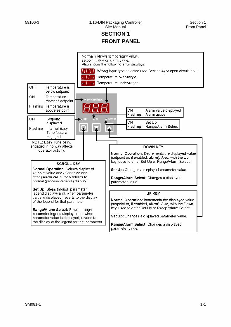
SEC TION 1FRONT PANEL
SM081-1 1-1
59106-3 1/16- DIN Pack ag ing Con trol ler Sec tion 1Site Man ual Front Panel
SEC TION 2INSTALLATION - PANEL-MOUNTING
2.1 UN PACK ING THE IN STRU MENT
1. Re move the Con trol ler from its pack ing. The Con trol ler is sup plied with a panelgas ket and a “no tools re quired” fix ing strap. Re tain the pack ing for fu ture use (e.g. mov ing the Con trol ler to a dif fer ent site).
2. Ex am ine the de liv ered items for dam age or de fi cien cies. If any is found, no tifythe car rier im me di ately.
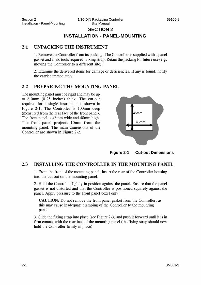
2.2 PREPARING THE MOUNTING PANEL
The mounting panel must be rigid and may be upto 6.0mm (0.25 inches) thick. The cut-outrequired for a single instrument is shown inFigure 2-1. The Controller is 100mm deep(measured from the rear face of the front panel).The front panel is 48mm wide and 48mm high.The front panel projects 10mm from themounting panel. The main dimensions of theController are shown in Figure 2-2.
2.3 INSTALLING THE CONTROLLER IN THE MOUNTING PANEL
1. From the front of the mount ing panel, in sert the rear of the Con trol ler hous inginto the cut- out on the mount ing panel.
2. Hold the Con trol ler lightly in po si tion against the panel. En sure that the panelgas ket is not dis torted and that the Con trol ler is po si tioned squarely against thepanel. Ap ply pres sure to the front panel bezel only.
CAUTION: Do not remove the front panel gasket from the Controller, as this may cause inadequate clamping of the Controller to the mountingpanel.
3. Slide the fix ing strap into place (see Fig ure 2-3) and push it for ward un til it is infirm con tact with the rear face of the mount ing panel (the fix ing strap should nowhold the Con trol ler firmly in place).
2-1 SM081-2
Sec tion 2 1/16- DIN Pack ag ing Con trol ler 59106-3In stal la tion - Panel- Mounting Site Man ual
Figure 2-1 Cut- out Di men sions
45mm
45mm

SM081-2 2-2
59106-3 1/16- DIN Pack ag ing Con trol ler Sec tion 2Site Man ual In stal la tion - Panel- Mounting
Figure 2-2 Main Di men sions
48m
48m
10mm approximately
110mm
Figure 2-3 Panel- mounting the Con trol ler
Fixing strap Rear face ofmounting panel
Housing
Tongues on fixing strapengage in ratchet slots onhousing
SEC TION 3INSTALLATION - WIRING CONNECTIONS
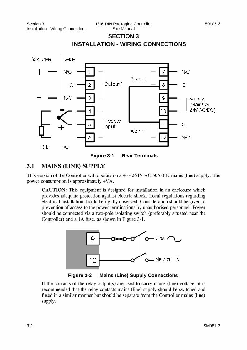
3.1 MAINS (LINE) SUPPLY
This version of the Controller will operate on a 96 - 264V AC 50/60Hz mains (line) supply. Thepower consumption is approximately 4VA.
CAUTION: This equipment is designed for installation in an enclosure whichprovides adequate protection against electric shock. Local regulations regardingelectrical installation should be rigidly observed. Consideration should be given toprevention of access to the power terminations by unauthorised personnel. Powershould be connected via a two-pole isolating switch (preferably situated near theController) and a 1A fuse, as shown in Figure 3-1.
If the contacts of the relay output(s) are used to carry mains (line) voltage, it isrecommended that the relay contacts mains (line) supply should be switched andfused in a similar manner but should be separate from the Controller mains (line)supply.
3-1 SM081-3
Sec tion 3 1/16- DIN Pack ag ing Con trol ler 59106-3In stal la tion - Wir ing Con nec tions Site Man ual
Figure 3-1 Rear Ter mi nals
Figure 3-2 Mains (Line) Sup ply Con nec tions

3.2 24V (NOMINAL) AC/DC SUPPLY
The supply connections for the 24V AC/DC version of the Controller are as shown in Figure 3-3.Power should be connected via a two-pole isolating switch and a 315mA slow-blow (anti-surgeType T) fuse. This version of the Controller will accept the following supply ranges:
24V (nomi nal) AC 50/60Hz - 20 - 50V24V (nomi nal) DC - 22 - 65V
3.3 THERMOCOUPLE INPUT
The correct type of thermocouple extension leadwire or compensating cable must be used for thefull distance between the Controller and the thermocouple, ensuring that the correct polarity isobserved throughout. Joints in the cable should be avoided, if possible.
NOTE: Do not run thermocouple cables adjacent to power-carrying conductors. Ifthe wiring is run in a conduit, use a separate conduit for the thermocouple wiring. If the thermocouple is grounded, this must be done at one point only. If thethermocouple extension lead is shielded, the shield must be grounded at one pointonly.
3.4 RTD INPUTS
The compensating lead should be connected to Terminal 4. For two-wire RTD inputs, Terminals 4and 5 should be linked. The extension leads should be of copper and the resistance of the wiresconnecting the resistance element should not exceed 5 ohms per lead (the leads should be of equallength).
3.5 RELAY OUTPUTS
The contacts are rated at 2A resistive at 120/240V AC.
3.6 SSR DRIVE OUTPUT
This output produces a time-proportioned non-isolated DC signal (0 - 10V nominal, into 500Ωminimum).
SM081-3 3-2
59106-3 1/16- DIN Pack ag ing Con trol ler Sec tion 3Site Man ual In stal la tion - Wir ing Con nec tions
Figure 3-3 24V AC/DC Sup ply Con nec tions

SEC TION 4SETTING UP - RANGE/ALARM SELECTION
Press the Scroll and Up keys simultaneously until the display starts to flash. Release the Scroll andUp keys then press the Down key. The SET UP indicator will flash and the display will show thelegend for the first parameter; after 1.5 seconds, the value of that parameter will be displayed. Usethe Scroll key to step through the parameters in the sequence shown below and opposite.
NOTES ON USE OF SCROLL KEY: When a legend is displayed,pressing this key will step to the legend for the next parameter; when avalue is displayed, pressing this key will display the legend for thatparameter.
4.1 CHANGING PARAMETER VALUES/SETTINGS
Use the Up and Down keys to change the displayed value/setting. All changes are implementedimmediately.
4.2 RETURNING TO NORMAL OPERATION
Press the Scroll key to display a parameter legend. While this legend is still displayed, press the Up and Down keys simultaneously for three seconds. NOTE: An automatic return to normal operation occurs if there is no key activity in Range/Alarm Selection Mode for one minute.
Parameter Displayed Legend
Available Values
Input Type and Range
4-1 SM081-4
Sec tion 4 1/16- DIN Pack ag ing Con trol ler 59106-3Set ting Up - Range/Alarm Se lec tion Site Man ual

Parameter Displayed Legend
Available Values
Control Action Reverse-acting PID control
Direct-acting PID control
Reverse-acting ON/OFF control
Direct-acting ON/OFF control
Alarm Type andAction (available only if an Alarm Option isfitted)
Process High Alarm, direct-acting
Process Low Alarm, direct-acting
Deviation Alarm, direct-acting
Band Alarm, direct-acting
Process High Alarm, reverse-acting
Process Low Alarm, reverse-acting
Deviation Alarm, reverse-acting
Band Alarm, reverse-acting
NOTES:
1. The RTD 0.0 range will always be 0.0 - 99.9, whatever the Range Maximum settingmay be.
2. Absolute Range Maximum = 400°C (700°F).
SM081-4 4-2
59106-3 1/16- DIN Pack ag ing Con trol ler Sec tion 4Site Man ual Set ting Up - Range/Alarm Se lec tion

4-3 SM081-4
Sec tion 4 1/16- DIN Pack ag ing Con trol ler 59106-3Set ting Up - Range/Alarm Se lec tion Site Man ual
Figure 4-1 Alarm Op era tion
Deviation HighAlarm
direct-acting
Deviation LowAlarm
direct-acting
Deviation HighAlarm
reverse-acting
Deviation LowAlarm
reverse-acting
Band Alarmdirect-acting
Band Alarmreverse-acting
Process LowAlarm
direct-acting
Process LowAlarm
reverse-acting
Process HighAlarm
direct-acting
Process HighAlarm
reverse-acting