, department of infrastructure, planning and natural ... · elizabeth madden, nsw agriculture...
TRANSCRIPT
Author
Sian McGhie, Department of Infrastructure, Planning and Natural Resources
Acknowledgments
Building Code Development and Reform Unit (Department of Infrastructure, Planning and Natural Resources), Cement and Concrete Association
Elizabeth Madden, NSW Agriculture
Melissa Ryan, Department of Infrastructure, Planning and Natural Resources
© Department of Infrastructure, Planning and Natural Resources 2003Department of Infrastructure, Planning and Natural Resources 2003
This booklet is copy under the Berne Convention All rights reserved No reproduction without permission
First published 2003 Department of Infrastructure, Planning and Natural Resources22-33 Bridge Street Sydney NSW 2000
Building in a Saline EnvironmentISBN: 0 7347 5375 6Designed and printed by ClickMedia, Penrith Photographs: various sources
American Concrete Institute, A Guide To The Use Of Waterproofing, Damp proofing, Protective and Decorative Barriers Systems For Concrete, American Concrete Institute, Detroit, Michigan.
Andrews-Phaedonos, F ( 1997) The Effects Of Aggressive Agents On The Expected Service Life Of Reinforced Concrete Structures, Concrete In Australia October - December 1997
AS 1547, Australian Standard 1547 - 2000 On Site Domestic Waste Water Management, Standards Australia.
AS 2159, Australian Standard 2159 - 1995 Piling - Design and installation. Standards Australia.
AS 2870, Australian Standard 2870 - 1996 Residential Slabs and Footings, Standards Australia.
AS 3600, Australian Standard 3600 - 2001 Concrete Structures, Standards Australia.
AS 3660.1, Australian Standard 3360.1 - 2000 Termite Management - New Building Work, Standards Australia.
AS 3700, Australian Standard 3700 - 2001 Masonry Structures, Standards Australia.
AS 3798, Australian Standard 3798 - 1996 Guidelines For Earthworks For Commercial and Residential Developments, Standards Australia.
AS 4419, Australian Standard 4419 - 1998 Soils For Landscaping and Garden Use, Standards Australia.
AS 4456.6, Australian Standard 4456.6 - 1997 Masonry Units and Segmental Pavers - Methods of Test -Determining Potential To Effloresce, Standards Australia.
AS 4456.10, Australian Standard 4456.10 - 1997 Masonry Units and Segmental Pavers - Method of Determining Resistance to Salt Attack, Standards Australia.
Building Code of Australia
Building Research Establishment, (1981) Digest 245 - Rising Damp In Walls: Diagnosis and Treatment, BRE, UK.
Department of Environment and Natural Resources (1995), Rising Damp and Salt Attack, State Heritage Branch and City Of Adelaide.
Department of Land and Water Conservation, Local Government Salinity Initiative booklets
* Site Investigations for Urban Salinity ( 2002)
* Broad Scale Resources for Urban Salinity Assessment ( 2002)
* Indicators of Urban Salinity (2002)
Department of Infrastructure, Planning and Natural Resources
* Roads and Salinity (2003)
Electricity Association of NSW, ( 1997), Corrosion In The Electricity Supply Industry, Electricity Association of NSW, ISBN 0 7313109 26
Guiguis,S. Technical Note 57, (1989) Durable Concrete Structures, Cement and Concrete Association Of Australia.
Guiguis,S. Technical Note 59, (1989) Hydaulic Cements - Properties and Characteristics, Cement and Concrete Association Of Australia.
Lume E. (1998?), Concrete In Saline Groundwater Environments, Cement and Concrete Association of Australia,
Massari G, Massari I, (1993), Damp Buildings Old and New, International Centre For The Study Of The Preservation And Restoration Of Cultural Property, Rome.
Patterson, R. (draft 2001) Septic Safe Technical Reference Sheet “ Consideration of Soil Salinity When Assessing Land Application of Effluent”, Department of Local Government.
South Australian Salt Damp Research Committee
* First Report of the Salt Damp Research Committee (1976)
* Second Report of the Salt Damp Research Committee Incorporating the Proceedings of the National Conference On Salt Damp.(1978)
* Third Report of the Salt Damp Research Committee (1981)
* How to Avoid Salt Damp (1978)
* Living With Salt Damp (1980)
References
17
Contents
Introduction 1
Sources of Water and Salt 2Infiltration Rates 3Porosity vs Permeability Porosity vs Permeability Porosity vs Permeability 3
The Reactions of Salts with Building MaterialsThe Reactions of Salts with Building Materials 5Concrete 5
Bricks Resistant to Salt and Water 7
Concrete Resistant to Salt and Water 8
Preventing Salt and Water Moving into the BuildingPreventing Salt and Water Moving into the Building 9
Maintaining Good Drainage on a Building SiteMaintaining Good Drainage on a Building Site 11
The Building Code of Australia 12
Australian Standards 13
References 17
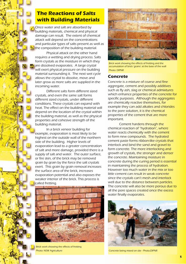
Salts are a natural part of the Australian landscape. Concentrated salt and different types of salt, once dissolved and mobilised in water, can have an impact on the durability of some building material. This booklet looks at:
1. how salts get into building material
2. the effect salt and water can have on some building materials.
Through the explanation of the processes, ideas are given on how to build structures that are less susceptible to salt damage. Other booklets of the Local Government Salinity Initiative kit, ‘Broad Scale Resources For Urban Salinity Assessment’ and ‘Site Investigations For Urban Salinity’, can be used to determine if salty groundwater or salty soil are likely to be affecting a building. ‘Indicators Of Urban Salinity’, gives a guide to the range of symptoms salt and water damage can create in an urban environment. ‘Roads and Salinity’ looks at how to construct a road so that it resists the effects of salinity and does not adversely impact on salt and water processes.
Render showing signs that excess salt and water are present
Photo: NSW Agriculture
Bricks showing signs of salt and water damage
Photo: NSW Agriculture
Paintwork blistering due to the accumulation of salt
Photo: DIPNR
Sandstone showing signs of salt and water damage
Photo: NSW Agriculture
Introduction
Verandah post showing signs of salt and water damage
Salinity and the Electricity Industry
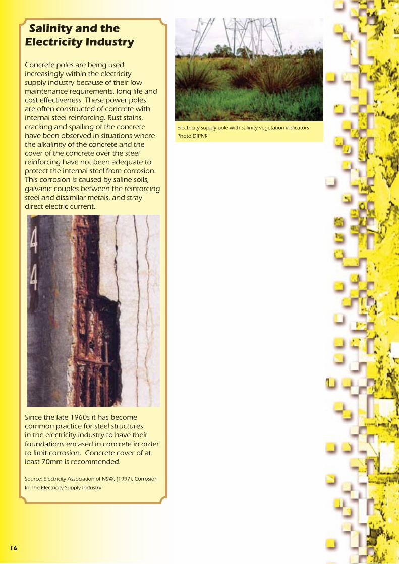
Concrete poles are being used increasingly within the electricity supply industry because of their low maintenance requirements, long life and cost effectiveness. These power poles are often constructed of concrete with internal steel reinforcing. Rust stains, cracking and spalling of the concrete have been observed in situations where the alkalinity of the concrete and the cover of the concrete over the steel reinforcing have not been adequate to protect the internal steel from corrosion. This corrosion is caused by saline soils, galvanic couples between the reinforcing steel and dissimilar metals, and stray direct electric current.
Since the late 1960s it has become common practice for steel structures in the electricity industry to have their foundations encased in concrete in order to limit corrosion. Concrete cover of at least 70mm is recommended.
Source: Electricity Association of NSW, (1997), Corrosion
In The Electricity Supply Industry
Electricity supply pole with salinity vegetation indicators
Photo:DIPNR
116

of the damp-proof course or termite barrier effectively providing a bridge for moisture or termites. Cutting the render at the height of the membrane is an ineffective solution. Over time, dust, dirt and salt crystals can easily bridge a small horizontal cut in the render.
• AS 3700 Masonry Structures, provides a table for durability requirements for exposure environments which includes the minimum salt attack resistance of masonry units, minimum mortar classification, minimum durability of built components and minimum cover to reinforcement.
• AS 2870 Residential Slabs and Footingspresently requires:
• a design life of 50 years (clause 1.4.2)
• drainage to be designed and constructed to avoid the ponding of water against or near footings. A graded fall of 50mm minimum away from the footing over a distance of 1m even on the ground uphill from the slab on cut and fill sites is required (clause 5.2.1)
• 40mm cover to reinforcement
• concrete to be vibrated and cured for at least 3 days in known salt damp areas (clause 6.4.8)
• careful detailing of damp-proof courses in high salt damp areas (clause 5.3.4)
• Damp-proof membranes to be extended under the edge beam to ground level ( clause 5.3.3.3)
and provides an advisory note to use damp-proof membranes in South Australia and areas prone to rising damp and salt attack (clause 5.3.2).
A committee was formed in early 2003 to review the requirements of this standard.
• AS 3600 Concrete Structures. This standard contains a detailed section on durability considerations.
Due to the levels of salts and water that accumulate over time in dryland salinity hazard areas it could be argued that the concrete requirements for moderately aggressive to aggressive environments detailed in AS 3600 should be considered for concrete structures. The following table compares the differences in requirements for the different environments.
These requirements are for a design life of 50 years yet in many cases it would be desirable to construct longer lasting homes and buildings.
Some of the construction and product standards have recommendations that can be overridden by professional expertise based on experience with the product. It is therefore important that members of the design and construction industry become more aware of the processes and impacts of urban salinity.
Non exposure grade bricks used in a garden wall
Photo: NSW Agriculture
non aggressive environment
B2 ( moderately aggressive environment)
C ( aggressive environment )
concrete strength 20M Pa 40M Pa 50M Pacuring time 3days 7days 7dayscover to reinforcing 40mm 45mm 50mm
Internal sources:• Condensation, where water vapour
in the air can condense on cooler wall surfaces. Examples can include hot moist air from clothes driers, cooking, showers, unventilated combustion heaters, people breathing.
It is important to carefully investigate the source or sources of the water in order to determine the most effective course of action. Massari and Massari (1993) quote an example where a building built in a swamp showed signs of moisture damage on the walls fronting the courtyard. Investigations showed the foundations of the building were such that the moisture from the swampy ground was not affecting the building. The cause of the problem was the downpipes in the courtyard discharging roof water onto the paving of the courtyard which in turn sloped towards the building.
Building products may be made with various materials such as sand, aggregates and water that can contain salt. Alternatively the finished product may be stored in a location which allows the addition of salt carried by wind, rain or from the ground to enter the finished product.
Once the product is used in a building, sources of moisture, wind or rain can add further salt. Various coatings or treatments may also add to the type and quantity of salts present. For example magnesite was commonly used on the floors of apartment blocks during the 1960s and 70s to provide a fast level finish to the floor and for sound proofing. It has since been found that salts can leach out of the product, aiding corrosion of the reinforcing within the concrete.
It is important to understand the source or sources of the salt in order to
Salts dissolve in water. They can therefore move with water, into and around buildings. This occurs via either ‘external’ or ‘internal’ sources of water.
External sources:• Rising damp, where ground moisture
is drawn into the building material by capillary action
• Falling damp, where leaking gutters, downpipes, roofs etc allow water to run down into the building
Sources of Water and Salt
Building with wet ‘tide’ mark - Photo: NSW Agriculture
Courthouse showing symptoms of falling damp from a blocked gutter - Photo: NSW Agriculture
Rusted down pipe allowing rainwater to mobilise salts in the soil. - Photo: DIPNR
2 15

Bricks efflorescing - Photo: NSW Agriculture
determine the most effective course of action, if action is needed. In some cases salt may appear as efflorescence on the surface of bricks as salts from the manufacturing process come to the surface. This may be a visual effect but does not cause structural damage to the building. In other cases the impact of salt may be less visible but more significant.
Infiltration RatesThe three main factors driving the rate of water entering a building are:
1. Amount of available water. This is influenced by the depth to the ground- water table, leaking water, sewer and stormwater systems, the over watering of gardens and the timing, distribution and intensity of rainfall.
2. Rate of evaporation. This is affected by such things as ventilation, temperature, relative humidity and the amount of building surface exposed.
3. Permeability of the building material. This depends on pore size, distribution and continuity of the pores within a building material.
Bricks exhibiting signs of salt and water damage
Photo: DIPNR
Porosity vs. PermeabilityA material may be porous but not permeable. That is, a material may have lots of pore spaces and therefore can hold a lot of water but at the same time not allow water to pass through it. If pores:
• are isolated or closed,
• have a lining that can react with fluid to discourage movement, or
• are too small to be filled as the air they contain cannot escape,
then the material will have a low permeability.
Pore size varies between materials but also within a material. In theory, a pore size of 0.001 mm can support a 1m high column of water. If salts are present in the water then the surface tension of the water is increased and there is increased ‘pull’ up the pore tube. This is partially offset by the increased weight of the water column due to the salts dissolved in the water. Pore diameters in mortar and brickwork are in the range of 0.1 um ( 0.0001 mm) to 10 um (0.01 mm). Fine cracks in concrete and other products can also act as capillary tubes. Therefore there is the potential for water to move a long way up a brick wall if the wall is exposed to a source of water.
• AS 4419 Soils For Landscaping and Garden Use sets a requirement for the appropriate labelling of low density and organic soils with an electrical conductivity of 2.5dS/m or 1.2dS/m for soil blends and natural soils. The labelling is to give clear information about salinity and the types of plants that will tolerate high salinity. There is also a note that expert advice should be sought as removal or dilution of salts depends on various factors such as the amount of salt present, depth and permeability of the soil.
This highlights the need to be careful when importing extra salts on to a site. Once present, salt is usually difficult to remove. This is not only important for plant growth and soil structure, but also for infrastructure. Unwashed sands, bricks made with salty clays, concrete made with salty bore water, or bore water used to suppress dust all import extra salt onto a site. Building materials stored on salty ground or exposed to salty winds or rain for extended periods may also pick up salts. Once concentrated within a building, salt may appear as efflorescence, cause corrosion to metals or cause physical and chemical damage to building materials even though the surrounding soil is showing low levels of salt. Many salts are hygroscopic, attracting water from sources such as dew. The salts are then easily mobilised within the structure causing the area of damage to increase until the salt is removed.
• AS 3798 Guidelines For Earthworks For Commercial and Residential Development contains various snippets of information that relate to salinity, for example:
• Site investigations should include identification of special areas relating to groundwater.
• Unsuitable materials for fill include those materials containing substances that can be dissolved or leached out [salt].
• Moisture content of fill should not be increased with saline water without field or laboratory trials. This should also be avoided in areas where steel will be buried or where revegetation will occur or areas that are to be later covered by bitumen.
• Special consideration of saline, chemically aggressive or polluted soils is needed to determine if they are suitable for fill.
• AS 3660.1 Termite Management - New Building Work, aims to deter the concealed entry of termites into new buildings above the termite barrier. However, as termites can damage soft concrete, enter through mortar joints and are attracted to damp areas, some of the recommendations for termite protection are also relevant for salinity protection. For example:
• Perimeter paths and areas under the house should be graded to prevent ponding.
• For slab on ground construction, concrete should be compacted and cured. This enhances the structural performance of the slab and increases resistance to penetration by termites.
• How to lay a barrier membrane to ensure the whole building is effectively protected without gaps.
• Finish a barrier membrane flush with the outside face of render rather than inside face.
Often render is applied over the edge
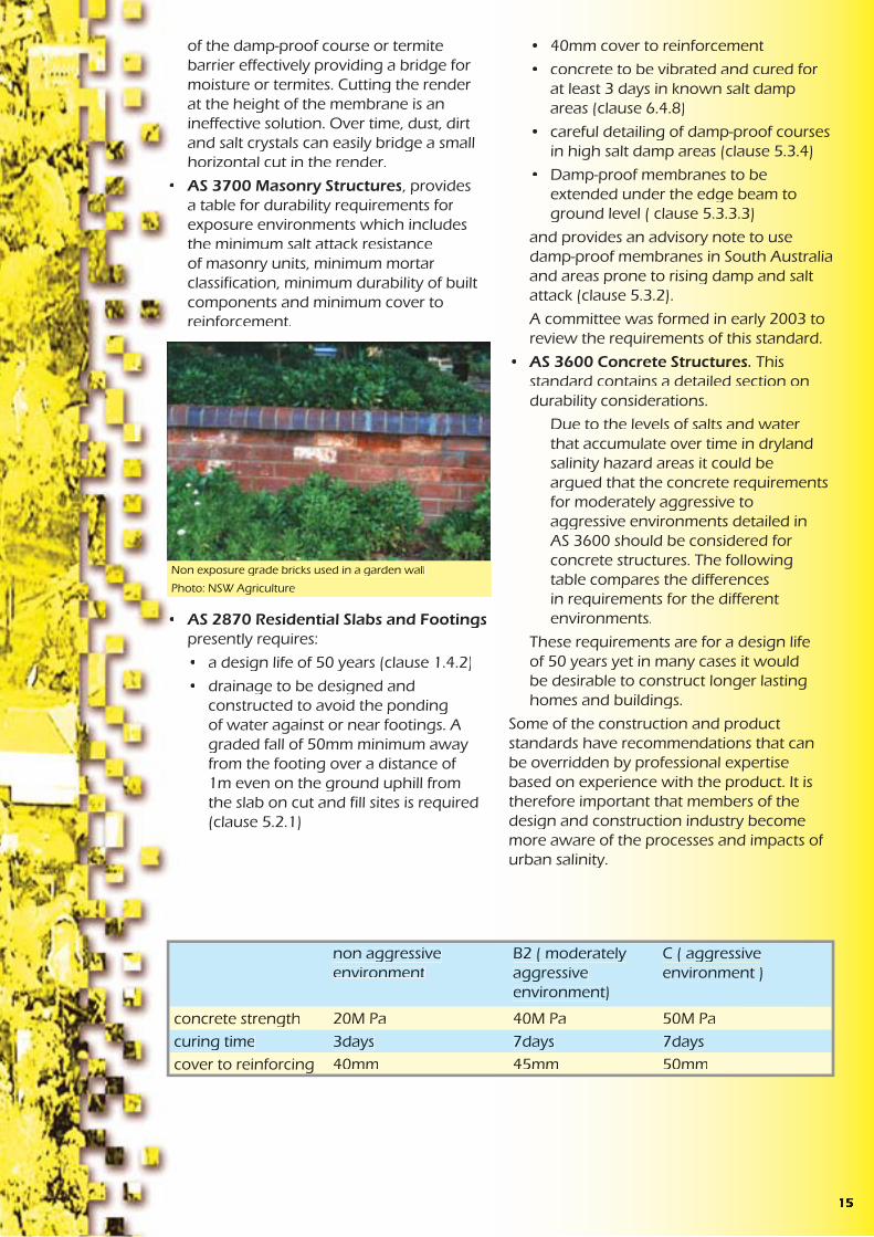
Typical earthworks on a residential building site
Photo: DIPNR
314

Moisture moves through material towards the surface where evaporation is occurring. The tide mark or height of the water on the wall is the point where the rate of evaporation equals the amount of water getting into, and moving through, the wall. Construction that maintains low permeability, allows increased ventilation and decreased contact between building materials, so sources of water are less likely to cause large areas of salt and water damage.
Source: Department of Environment and Natural Resources (1995), Rising Damp and Salt Attack, State Heritage Branch and City of Adelaide
A non permeable render has decreased evaporation
Photo: NSW Agriculture
with consideration to developing suitable requirements for buildings in saline areas. The Australian Building Codes Board (ABCB) has established a Technical Working Group to review and comment on salt attack documents and proposals as they are produced or acquired by the ABCB.
In South Australia there are currently three additional requirement for the barriers installed to prevent ground moisture entering the building:
• a high resistance to moisture penetration
• a high resistance to damage during construction and
• a high resistance to degradation by dissolved salts.
There are various Australian Standards that have provisions that assist in the management of salinity. For example:
• AS 1547 - 2000 On Site Domestic Waste Water Management has a performance requirement for on-site waste water systems to avoid surface and groundwater pollution. The standard recommends construction and installation is undertaken only after suitable site investigations that include such things as changes in the groundwater table and sodicity.
On-site waste water disposal adds extra salts to the soil as well as extra liquid to the groundwater system. This can result in on-site and off-site impacts if not properly considered. More information on salinity and effluent is provided in the Septic Safe Technical Reference Sheet published by the Department of Local Government, ‘Consideration of Soil Salinity When Assessing Land Application of Effluent’ by Dr Robert Patterson. More information on site investigations for salinity is provided in the Local Government Salinity Initiative booklet, ‘Site Investigations for Urban Salinity’ by the former Department of Land and Water Conservation. (2002)
• AS 2159 Piling Design and Installation provides table (6.1) Exposure Classification For Concrete Piles. Soil conditions are listed as non-aggressive, mild, moderate, severe or very severe, based on test results for pH, chlorides, sulphates and soil resistivity, for permeable soils which are below the groundwater table and for low permeability soils or all soils above the groundwater table. Various notes of caution are attached to the table such as the impact of magnesium or ammonium ions which, in the presence of sulphates, increase the aggressiveness of the soil on concrete. This standard also recommends site specific design of concrete for sulphate attack noting that dense, well compacted, low permeable concrete of the correct type is more important than a high characteristic strength.
Extracts from this standard are provided in the Local Government Salinity Initiative booklet, ‘Site Investigations for Urban Salinity’.
Australian Standards
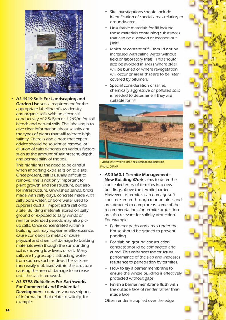
Typical slab on ground construction. - Photo: DIPNR
134
ConcreteConcrete is a mixture of coarse and fine aggregate, cement and possibly additives such as fly ash, slag or chemical admixtures which enhance properties of the concrete for specific purposes. Although the aggregates are chemically reactive themselves, for example they can add alkalies and chlorides to the pore solution, it is the chemical properties of the cement that are more important.
Cement hardens through the chemical reaction of “hydration”, where water reacts chemically with the cement to form new compounds. The hydrated cement paste forms ribbon-like crystals that interlock and bind the sand and gravel to form concrete. The more interlocking and growth of crystals, the stronger and denser the concrete. Maintaining moisture in concrete during the curing period is essential in maintaining the process of hydration. However too much water in the mix or too little cement can result in weak concrete since the crystals can’t mesh and interlock well due to the distance between particles. The concrete will also be more porous due to all the pore spaces created once the excess water finally evaporates.
Once water and salt are absorbed by building materials, chemical and physical damage can result. The extent of chemical attack will depend on the concentrations and particular types of salts present as well as the composition of the building material.
Physical attack on the other hand requires a wetting and drying process. Salts form crystals as the moisture in which they are dissolved evaporates. A large crystal will exert physical pressure on the building material surrounding it. The next wet cycle allows the crystal to dissolve, move and later grow as more salts are supplied in the incoming water.
Different salts form different sized crystals, and even the same salt forms different sized crystals, under different conditions. These crystals can expand with heat. The effect on the building material will depend on the location of the crystal within the building material, as well as the physical properties and cohesive strength of the building material.
In a brick veneer building for example, evaporation is most likely to be highest on the outside wall of the northern side of the building. Higher levels of evaporation lead to a greater concentration of salt and more damage, provided there is a supply of salt and water. The outer surface, or fire skin, of the brick may be removed grain by grain by the force the salt crystals exert. This grain by grain removal increases the surface area of the brick, increases evaporation potential and also exposes the weaker interior of the brick. This process is called fretting.
The Reactions of Salts with Building Materials
Brick work showing the effects of fretting
Photo: NSW Agriculture
Brick work showing the effects of fretting and the accumulation of brick ‘grains’ at the base of the wall
Photo: DIPNR
Concrete being mixed on site - Photo:DIPNR
The Building Code of Australia (BCA) includes some requirements for building in saline environments. For example, in Volume 2 of the BCA, clauses 3.3.1.5(b), 3.3.1.6 and 3.3.1.7(b). The BCA also references Australian Standards that contain requirements for buildings in a saline environment. Some examples of these Standards (AS 2159, AS 2870, AS 3700 and AS 3600) are detailed in the next section of this booklet.
There are some inclusions that are aimed at providing protection against moisture in general. These include:
• Part of Objective 2.2 of the BCA is to protect the building from damage caused by external moisture entering a building.
• Functional Statement 2.2.2 Weatherproofing and Dampness, includes “construction to provide resistance to moisture from the outside and moisture rising from the ground”. This doesn’t apply to class 10 buildings unless construction contributes to the weatherproofing of a class 1 building. Class 1 buildings being residences and class 10 being outbuildings and associated structures such as verandahs, garages, swimming pools, flag poles and carparks.
• Performance Requirement P2.2.3 for Dampness relates specifically to moisture from the ground and requires prevention of
• unhealthy or dangerous conditions, or loss of amenity for occupants
• undue dampness or deterioration of building elements.
This performance requirement does not apply to a class 10 building where in the particular case it is judged that there is no necessity for compliance.
However, the current provisions contained in the BCA related to preventing dampness were not intended to provide protection against rising salt damp (salt attack/salinity) and were aimed at providing protection against moisture in general. At the Australian Building Code Board’s 2001 National Technical Summit, the issue of urban salinity was discussed and it was agreed that a review of the BCA requirements to prevent moisture penetration was necessary,
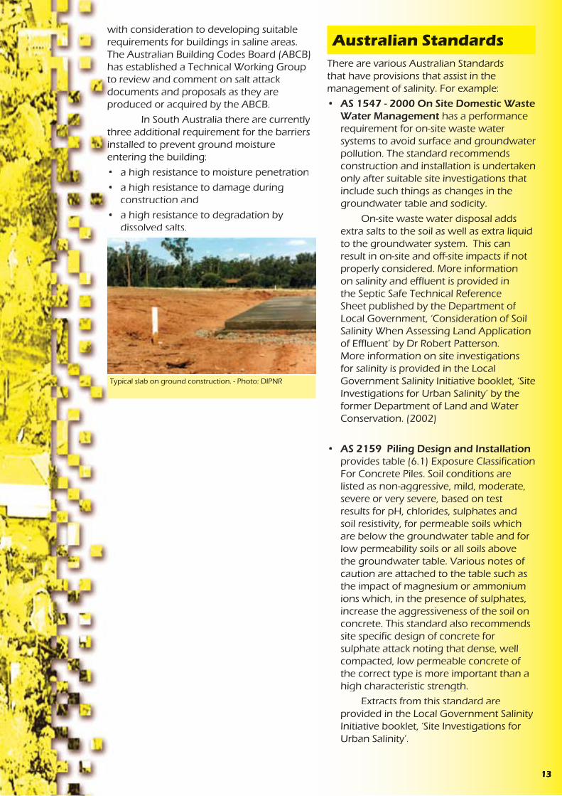
Water flow not obstructed by urban development
Diagram: DIPNR- Greener Subdivision project
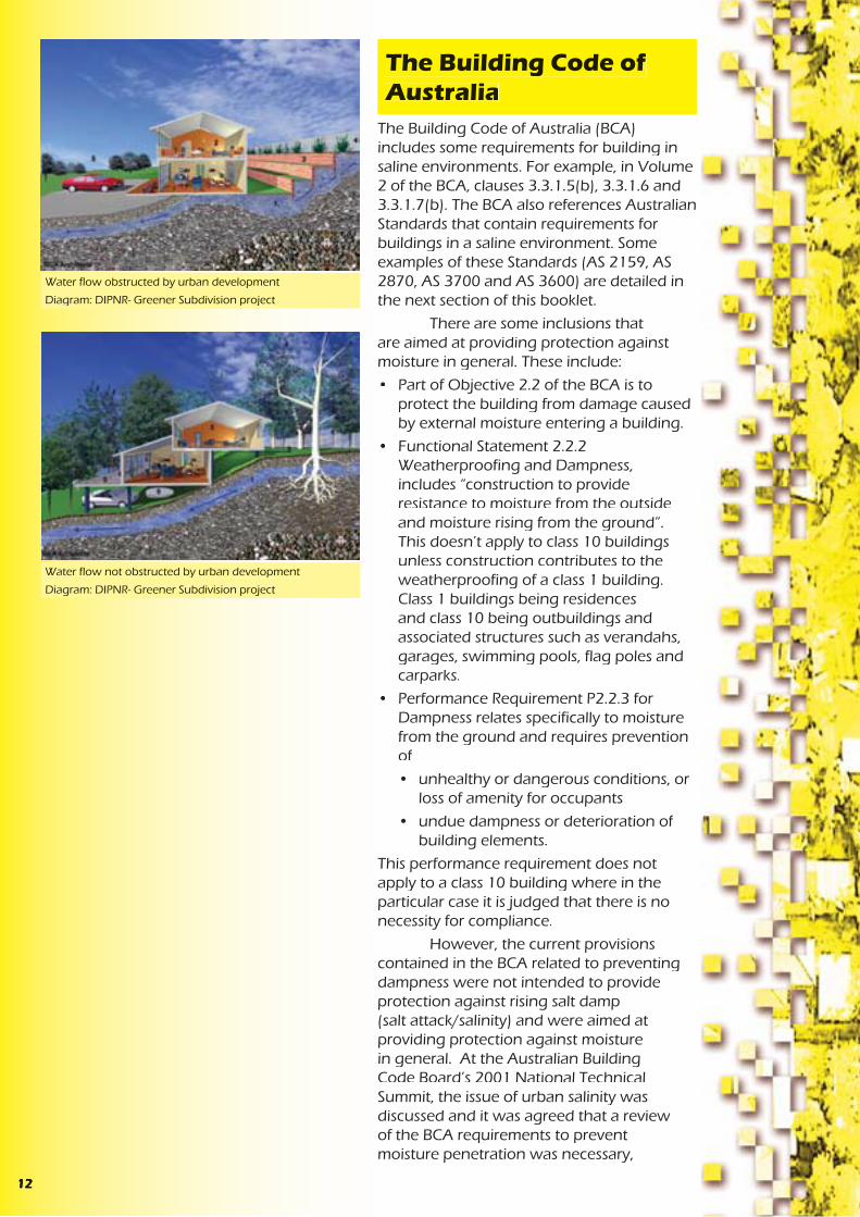
Water flow obstructed by urban development
Diagram: DIPNR- Greener Subdivision project
The Building Code of Australia
512
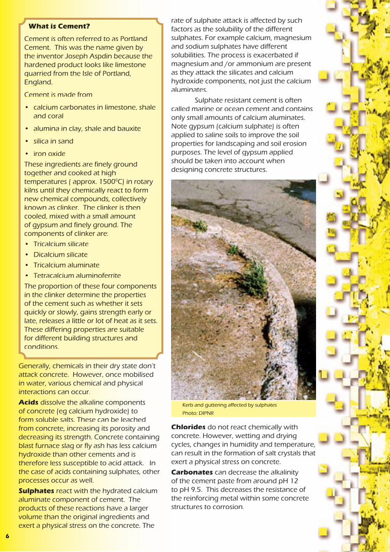
rate of sulphate attack is affected by such factors as the solubility of the different sulphates. For example calcium, magnesium and sodium sulphates have different solubilities. The process is exacerbated if magnesium and /or ammonium are present as they attack the silicates and calcium hydroxide components, not just the calcium aluminates.
Sulphate resistant cement is often called marine or ocean cement and contains only small amounts of calcium aluminates. Note gypsum (calcium sulphate) is often applied to saline soils to improve the soil properties for landscaping and soil erosion purposes. The level of gypsum applied should be taken into account when designing concrete structures.
Chlorides do not react chemically with concrete. However, wetting and drying cycles, changes in humidity and temperature, can result in the formation of salt crystals that exert a physical stress on concrete.
Carbonates can decrease the alkalinity of the cement paste from around pH 12 to pH 9.5. This decreases the resistance of the reinforcing metal within some concrete structures to corrosion.
Kerb and guttering affected by sulphates
Photo: DIPNR
Generally, chemicals in their dry state don’t attack concrete. However, once mobilised in water, various chemical and physical interactions can occur.
Acids dissolve the alkaline components of concrete (eg calcium hydroxide) to form soluble salts. These can be leached from concrete, increasing its porosity and decreasing its strength. Concrete containing blast furnace slag or fly ash has less calcium hydroxide than other cements and is therefore less susceptible to acid attack. In the case of acids containing sulphates, other processes occur as well.
Sulphates react with the hydrated calcium aluminate component of cement. The products of these reactions have a larger volume than the original ingredients and exert a physical stress on the concrete. The
What is Cement?
Cement is often referred to as Portland Cement. This was the name given by the inventor Joseph Aspdin because the hardened product looks like limestone quarried from the Isle of Portland, England.
Cement is made from
• calcium carbonates in limestone, shale and coral
• alumina in clay, shale and bauxite
• silica in sand
• iron oxide
These ingredients are finely ground together and cooked at high temperatures ( approx. 15000C) in rotary kilns until they chemically react to form new chemical compounds, collectively known as clinker. The clinker is then cooled, mixed with a small amount of gypsum and finely ground. The components of clinker are:
• Tricalcium silicate
• Dicalcium silicate
• Tricalcium aluminate
• Tetracalcium aluminoferrite
The proportion of these four components in the clinker determine the properties of the cement such as whether it sets quickly or slowly, gains strength early or late, releases a little or lot of heat as it sets. These differing properties are suitable for different building structures and conditions.
The movement of water at various scales needs to be considered with respect to the mobilisation of salt. On a catchment scale, water may be entering a groundwater system kilometres away from where the water returns to the surface. Along the way this water may have picked up salt from the rocks and soils it has passed through. In this situation, on-site action as well as work further up the catchment where the water is getting into the groundwater system could be more cost effective.
On a subdivision scale, decisions such as whether to use septic tanks, irrigate treated effluent, infiltrate stormwater, supply piped potable water, and how much native vegetation to retain, all impact on the salt and water movement. A salt and water balance should be undertaken to estimate the impact of the development on the salinity processes on and off site. If the environmental, social and economic costs are too high, an alternative decision should be made with respect to the aspect of the development causing the excess salt and water. Alternatively a long term monitoring, evaluation and management plan could be put in place to deal with potential adverse impacts.
On an individual house lot scale, construction and maintenance decisions such as:
• whether to cut or fill the site
• whether the ground is reshaped to slope away from the building
• how the site is landscaped
• how the landscaping is watered
• how much of the site is hard surfaces vs pervious surfaces
• whether a path is provided around the perimeter of the house and sloping away from the building
• what stormwater drainage is provided behind retaining walls
• whether pools, taps, and downpipes are regularly checked for leaks
all affect the amount of water on the site and how it is moving around the structure to be protected from salinity damage.
and areas prone to rising damp and salt attack. The extra cost is around $50 for a 140m2 house. Damp-proof membranes are more resistant to puncturing and stop water if there is no hydrostatic pressure.
Care should be taken when installing the damp-proof membrane to ensure it extends completely under the whole slab and up the sides to at least finished ground level. This prevents moisture moving in from the sides or through gaps. AS 2870 only permits ‘vapour’, not ‘damp’, barriers to be terminated at the internal face of external beams. The standard also sets requirements for the lapping of joints and taping of penetrations for pipes or plumbing fittings. However local plumbers and builders may not be aware of salinity hazard areas or of the importance of this work in such areas.
Care should also be taken laying the reinforcing and walking on the laid membrane prior to pouring of the concrete slab as these activities may result in small holes. Puncturing the membrane to allow excess water from the concrete to escape and speed up curing is also poor practice. Short curing times usually result in a more permeable concrete slab more susceptible to salt damp attack. If the water table is sufficiently high after construction or during the life of the building, then the puncture holes will allow moisture under the slab to move into the slab.
Maintaining Good Drainage on a Building Site
116

It is common practice at present in NSW to construct buildings with concrete floors essentially laying at ground level. Under the concrete slab, there is usually a layer of sand and a vapour-proof plastic that acts as the damp-proof course for the concrete slab. A damp-proof course is also installed in a mortar joint of the brickwork forming the walls of the building.
The sand layer provides a number of functions in relation to salinity. Firstly, it helps prevent membrane puncture from hard material in the underlaying soil. It also decreases the capillary rise of any soil moisture since the sand grains are quite far apart ie there are large pore spaces. Increasing this sand layer is one method that has been suggested1 to increase the protection of structures from salinity.
Previously, floors rested on bearers and joists, supported by piers. This type of construction has less building material in contact with possible salt and water sources in the ground. It more readily allows ventilation, evaporation and the concentration of salts to occur in the soil rather than building materials. It is also less likely to impact on natural salt and water processes.
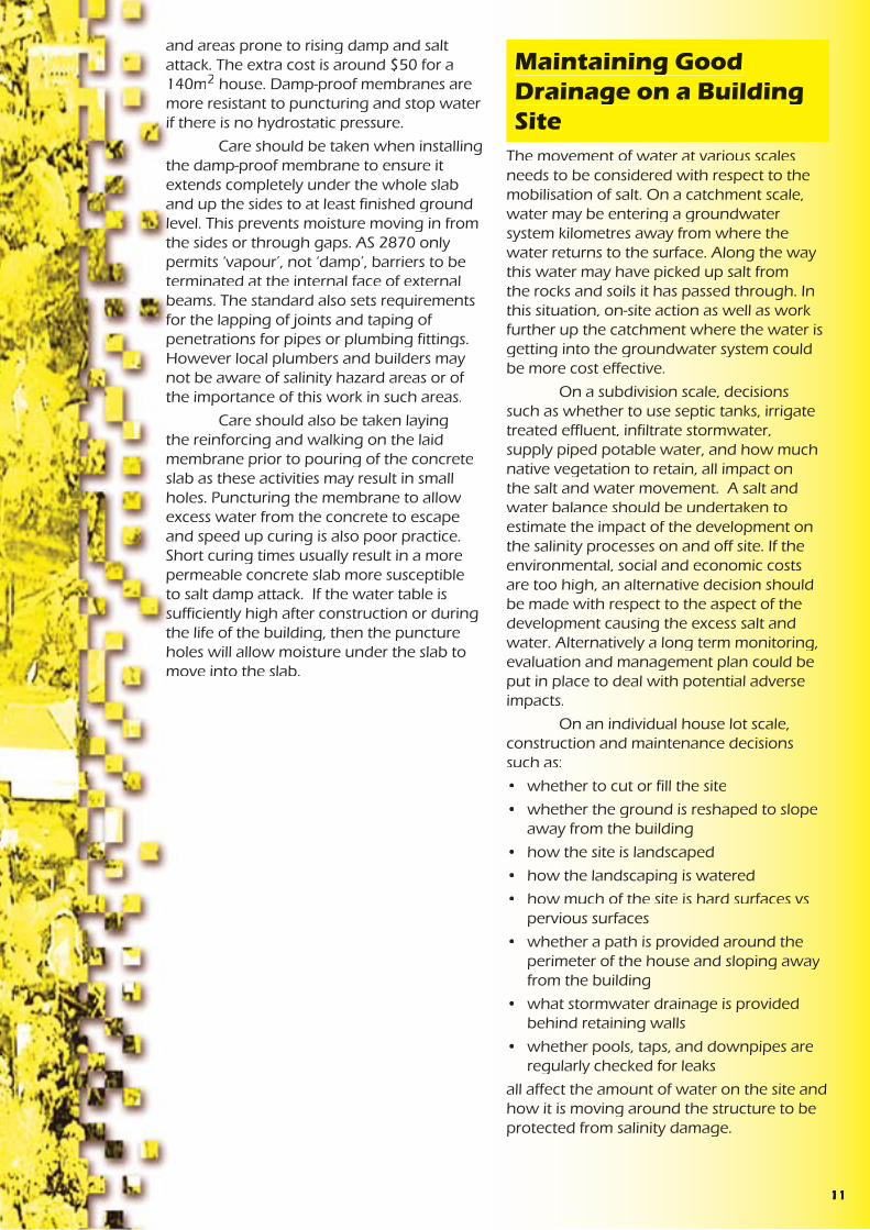
The Australian building code presently requires a minimum clearance of 400mm between the ground and suspended floors to allow ease of access for termite inspection. This also allows a visual inspection for salinity damage to piers.
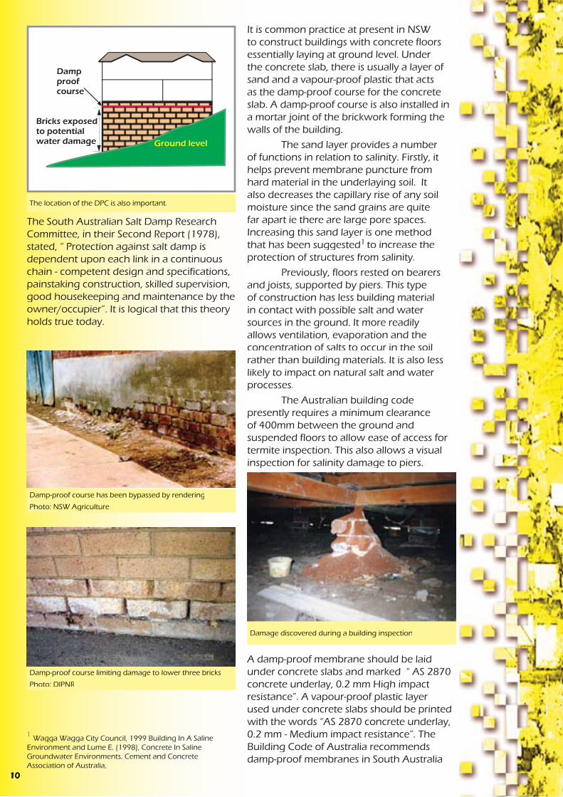
A damp-proof membrane should be laid under concrete slabs and marked “ AS 2870 concrete underlay, 0.2 mm High impact resistance”. A vapour-proof plastic layer used under concrete slabs should be printed with the words “AS 2870 concrete underlay, 0.2 mm - Medium impact resistance”. The Building Code of Australia recommends damp-proof membranes in South Australia
Damp-proof course has been bypassed by rendering
Photo: NSW Agriculture
Damp-proof course limiting damage to lower three bricks
Photo: DIPNR
Damage discovered during a building inspection
1 Wagga Wagga City Council, 1999 Building In A Saline Environment and Lume E. (1998), Concrete In Saline Groundwater Environments, Cement and Concrete Association of Australia,
The South Australian Salt Damp Research Committee, in their Second Report (1978), stated, “ Protection against salt damp is dependent upon each link in a continuous chain - competent design and specifications, painstaking construction, skilled supervision, good housekeeping and maintenance by the owner/occupier”. It is logical that this theory holds true today.
The location of the DPC is also important.
Corrosion of reinforcement in concreteoccurs in 2 phases, namely initiation and propagation. The initiation phase occurs when the alkalinity of the concrete is reduced by carbonation or ionization. Carbonates may come from sources such as groundwater or carbon dioxide in the air. Ionization occurs where there is a higher concentration of reactive ions such as chlorides. Chlorides may come from groundwater, the atmosphere, acid etching, admixtures, or the water, aggregate and sand used to make the concrete. Once initiated, the propagation phase of the corrosion continues at a rate dependent on the amount of available oxygen, moisture, reactive ions and remaining alkalinity.
It is therefore important to know the site conditions and chemicals that the building will be exposed to, so that a suitable type of building material can be chosen and installed. Careful site supervision and quality control is then required to ensure consistency in the production of mortar and other products mixed on site or at batching plants.
Reinforcing steel exposed and corrodingPhoto: DIPNR
Bricks that are less susceptible to damage from salt and water:
• are less permeable so the salt and water cannot penetrate
• do not contain excessive amounts of salts, thus are not adding more salt to the process
• have good internal strength so that they can withstand the physical stress created by the formation of salt crystals
The Building Code of Australia (BCA), Part 3.3.1, requires masonry units to be classified and used in the exposure conditions appropriate to their classification. Table 3.3.1.1 of the BCA states exposure class is “Suitable for use in all classifications including severe local conditions such as:
a) below the damp-proof course in areas where walls are expected to be attacked by salts in the groundwater or brickwork itself ( salt attack or salt damp)
.....
c) In retaining walls.”
The BCA also gives the ratio of cement, lime and sand suitable for mortars, prohibits raked mortar joints in areas requiring exposure class bricks, and requires mortar to be made with potable, not salty, water.
Methods to test the properties of bricks can be found in Australian Standards. Australian Standard 4456.6 Masonry Units and Segmental Pavers - Methods of Test - Determining Potential To Effloresce, compares couples of masonry units where one brick of the pair has been soaked in water for 7 days and then air dried, and the other brick is untreated. A ranking is then given to each batch of bricks ( nil, slight, moderate, heavy or severe) based on
Bricks Resistant to Salt and Water
710
the amount of efflorescence on the outer surface of the treated unit. This test gives an indication of the amount of salt accumulated in the brick from the production and storage process.
Australian Standard 4456.1 Masonry Units and Segmental Pavers - Method of Determining Resistance to Salt Attack, is a test that is used to classify a brick’s resistance to salt attack. Bricks are soaked in a salt solution of either sodium sulphate or sodium chloride and then dried. This is repeated up to 40 times and the amount of damage assessed by comparing the weight of the bricks before and after the process. Bricks are then rated as ‘exposure’, ‘protected’ or ‘general purpose’ class. Satisfactory performance of a sample in a sodium sulphate solution usually guarantees satisfactory performance in a sodium chloride solution but not vice versa. This is presumably due to the sulphate chemical reactions mentioned previously.
Concrete Resistant to Salt and Water
Durability of concrete depends on internal factors such as constituents as well as external factors such as design and construction.
Permeability is a very important factor with regard to rising damp. The more permeable the concrete, the less durable it will be. Permeability depends on pore size, pore distribution and the continuity of pores. Voids are formed by excess water in the mix, incomplete compaction, and incomplete curing which allows concrete to dry out prematurely.
In order to improve the durability of concrete in moist saline environments, consider:
• Proper compaction of the concrete
• Reducing the water cement ratio
• Proper curing procedures and duration
• Choice of appropriate concrete materials (ie cement type, sands and aggregate) for the site conditions
• Increasing the concrete cover over steel reinforcement
• Minimising cracks
• Minimising ponding of water on or next to concrete
• Minimising turbulence of any water flowing over a concrete structure
• A smooth surface
• Increasing the cement content
• Using a quality assurance certified supplier
All other factors being equal, increasing the strength of concrete will decrease its permeability. As there is no standard test for permeability in cement, strength is often used as an ‘indicator’ of permeability. However, this is an oversimplification and should not be used as the only specification or design criteria for ensuring concrete structures are durable in salinity hazard landscapes.
A damp-proof course is a layer of water impermeable material commonly installed in buildings close to ground level. In the past, damp-proof courses have been made of various materials including coal tar, slate, metal and mortars containing chimney soot. Today, it is common for the damp proof course to be a polyethylene sheeting laid in a mortar joint of the brick work.
A damp-proof course should restrict any damage from rising damp to the area below the damp-proof course. However, a damp- proof course (DPC) may:
• break down due to chemical decomposition
• be cracked or penetrated during installation
• be broken by the differential settling of the building
• be incorrectly installed
• be bridged by pointing or rendering
• be bridged by the installation of garden beds and paving
• be bridged by mortar droppings in the wall cavity
• be bridged by renovations or additions, eg incorrect replacement of a timber floor with sand and a concrete slab
Once the damp-proof course is bridged or broken, water and any salts it contains are able to move upwards. This significantly increases the difficulty and cost of repairing salinity damage to buildings. Correctly installing and maintaining a durable damp- proof course is therefore an important technique in controlling salt damage to buildings.
Preventing Salt and Water Moving into the Building
Installation of polyethylene sheeting in mortar joint of the brick work - Photo: DIPNR
Source: Department of Environment and Natural Resources (1995), Rising Damp and Salt Attack, State Heritage Branch and City Of Adelaide.
98
It is common practice at present in NSW to construct buildings with concrete floors essentially laying at ground level. Under the concrete slab, there is usually a layer of sand and a vapour-proof plastic that acts as the damp-proof course for the concrete slab. A damp-proof course is also installed in a mortar joint of the brickwork forming the walls of the building.
The sand layer provides a number of functions in relation to salinity. Firstly, it helps prevent membrane puncture from hard material in the underlaying soil. It also decreases the capillary rise of any soil moisture since the sand grains are quite far apart ie there are large pore spaces. Increasing this sand layer is one method that has been suggested1 to increase the protection of structures from salinity.
Previously, floors rested on bearers and joists, supported by piers. This type of construction has less building material in contact with possible salt and water sources in the ground. It more readily allows ventilation, evaporation and the concentration of salts to occur in the soil rather than building materials. It is also less likely to impact on natural salt and water processes.
The Australian building code presently requires a minimum clearance of 400mm between the ground and suspended floors to allow ease of access for termite inspection. This also allows a visual inspection for salinity damage to piers.
A damp-proof membrane should be laid under concrete slabs and marked “ AS 2870 concrete underlay, 0.2 mm High impact resistance”. A vapour-proof plastic layer used under concrete slabs should be printed with the words “AS 2870 concrete underlay, 0.2 mm - Medium impact resistance”. The Building Code of Australia recommends damp-proof membranes in South Australia
Damp-proof course has been bypassed by rendering
Photo: NSW Agriculture
Damp-proof course limiting damage to lower three bricks
Photo: DIPNR
Damage discovered during a building inspection
1 Wagga Wagga City Council, 1999 Building In A Saline Environment and Lume E. (1998), Concrete In Saline Groundwater Environments, Cement and Concrete Association of Australia,
The South Australian Salt Damp Research Committee, in their Second Report (1978), stated, “ Protection against salt damp is dependent upon each link in a continuous chain - competent design and specifications, painstaking construction, skilled supervision, good housekeeping and maintenance by the owner/occupier”. It is logical that this theory holds true today.
The location of the DPC is also important.
Corrosion of reinforcement in concreteoccurs in 2 phases, namely initiation and propagation. The initiation phase occurs when the alkalinity of the concrete is reduced by carbonation or ionization. Carbonates may come from sources such as groundwater or carbon dioxide in the air. Ionization occurs where there is a higher concentration of reactive ions such as chlorides. Chlorides may come from groundwater, the atmosphere, acid etching, admixtures, or the water, aggregate and sand used to make the concrete. Once initiated, the propagation phase of the corrosion continues at a rate dependent on the amount of available oxygen, moisture, reactive ions and remaining alkalinity.
It is therefore important to know the site conditions and chemicals that the building will be exposed to, so that a suitable type of building material can be chosen and installed. Careful site supervision and quality control is then required to ensure consistency in the production of mortar and other products mixed on site or at batching plants.
Reinforcing steel exposed and corrodingPhoto: DIPNR
Bricks that are less susceptible to damage from salt and water:
• are less permeable so the salt and water cannot penetrate
• do not contain excessive amounts of salts, thus are not adding more salt to the process
• have good internal strength so that they can withstand the physical stress created by the formation of salt crystals
The Building Code of Australia (BCA), Part 3.3.1, requires masonry units to be classified and used in the exposure conditions appropriate to their classification. Table 3.3.1.1 of the BCA states exposure class is “Suitable for use in all classifications including severe local conditions such as:
a) below the damp-proof course in areas where walls are expected to be attacked by salts in the groundwater or brickwork itself ( salt attack or salt damp)
.....
c) In retaining walls.”
The BCA also gives the ratio of cement, lime and sand suitable for mortars, prohibits raked mortar joints in areas requiring exposure class bricks, and requires mortar to be made with potable, not salty, water.
Methods to test the properties of bricks can be found in Australian Standards. Australian Standard 4456.6 Masonry Units and Segmental Pavers - Methods of Test - Determining Potential To Effloresce, compares couples of masonry units where one brick of the pair has been soaked in water for 7 days and then air dried, and the other brick is untreated. A ranking is then given to each batch of bricks ( nil, slight, moderate, heavy or severe) based on
Bricks Resistant to Salt and Water
710
rate of sulphate attack is affected by such factors as the solubility of the different sulphates. For example calcium, magnesium and sodium sulphates have different solubilities. The process is exacerbated if magnesium and /or ammonium are present as they attack the silicates and calcium hydroxide components, not just the calcium aluminates.
Sulphate resistant cement is often called marine or ocean cement and contains only small amounts of calcium aluminates. Note gypsum (calcium sulphate) is often applied to saline soils to improve the soil properties for landscaping and soil erosion purposes. The level of gypsum applied should be taken into account when designing concrete structures.
Chlorides do not react chemically with concrete. However, wetting and drying cycles, changes in humidity and temperature, can result in the formation of salt crystals that exert a physical stress on concrete.
Carbonates can decrease the alkalinity of the cement paste from around pH 12 to pH 9.5. This decreases the resistance of the reinforcing metal within some concrete structures to corrosion.
Kerb and guttering affected by sulphates
Photo: DIPNR
Generally, chemicals in their dry state don’t attack concrete. However, once mobilised in water, various chemical and physical interactions can occur.
Acids dissolve the alkaline components of concrete (eg calcium hydroxide) to form soluble salts. These can be leached from concrete, increasing its porosity and decreasing its strength. Concrete containing blast furnace slag or fly ash has less calcium hydroxide than other cements and is therefore less susceptible to acid attack. In the case of acids containing sulphates, other processes occur as well.
Sulphates react with the hydrated calcium aluminate component of cement. The products of these reactions have a larger volume than the original ingredients and exert a physical stress on the concrete. The
What is Cement?
Cement is often referred to as Portland Cement. This was the name given by the inventor Joseph Aspdin because the hardened product looks like limestone quarried from the Isle of Portland, England.
Cement is made from
• calcium carbonates in limestone, shale and coral
• alumina in clay, shale and bauxite
• silica in sand
• iron oxide
These ingredients are finely ground together and cooked at high temperatures ( approx. 15000C) in rotary kilns until they chemically react to form new chemical compounds, collectively known as clinker. The clinker is then cooled, mixed with a small amount of gypsum and finely ground. The components of clinker are:
• Tricalcium silicate
• Dicalcium silicate
• Tricalcium aluminate
• Tetracalcium aluminoferrite
The proportion of these four components in the clinker determine the properties of the cement such as whether it sets quickly or slowly, gains strength early or late, releases a little or lot of heat as it sets. These differing properties are suitable for different building structures and conditions.
The movement of water at various scales needs to be considered with respect to the mobilisation of salt. On a catchment scale, water may be entering a groundwater system kilometres away from where the water returns to the surface. Along the way this water may have picked up salt from the rocks and soils it has passed through. In this situation, on-site action as well as work further up the catchment where the water is getting into the groundwater system could be more cost effective.
On a subdivision scale, decisions such as whether to use septic tanks, irrigate treated effluent, infiltrate stormwater, supply piped potable water, and how much native vegetation to retain, all impact on the salt and water movement. A salt and water balance should be undertaken to estimate the impact of the development on the salinity processes on and off site. If the environmental, social and economic costs are too high, an alternative decision should be made with respect to the aspect of the development causing the excess salt and water. Alternatively a long term monitoring, evaluation and management plan could be put in place to deal with potential adverse impacts.
On an individual house lot scale, construction and maintenance decisions such as:
• whether to cut or fill the site
• whether the ground is reshaped to slope away from the building
• how the site is landscaped
• how the landscaping is watered
• how much of the site is hard surfaces vs pervious surfaces
• whether a path is provided around the perimeter of the house and sloping away from the building
• what stormwater drainage is provided behind retaining walls
• whether pools, taps, and downpipes are regularly checked for leaks
all affect the amount of water on the site and how it is moving around the structure to be protected from salinity damage.
and areas prone to rising damp and salt attack. The extra cost is around $50 for a 140m2 house. Damp-proof membranes are more resistant to puncturing and stop water if there is no hydrostatic pressure.
Care should be taken when installing the damp-proof membrane to ensure it extends completely under the whole slab and up the sides to at least finished ground level. This prevents moisture moving in from the sides or through gaps. AS 2870 only permits ‘vapour’, not ‘damp’, barriers to be terminated at the internal face of external beams. The standard also sets requirements for the lapping of joints and taping of penetrations for pipes or plumbing fittings. However local plumbers and builders may not be aware of salinity hazard areas or of the importance of this work in such areas.
Care should also be taken laying the reinforcing and walking on the laid membrane prior to pouring of the concrete slab as these activities may result in small holes. Puncturing the membrane to allow excess water from the concrete to escape and speed up curing is also poor practice. Short curing times usually result in a more permeable concrete slab more susceptible to salt damp attack. If the water table is sufficiently high after construction or during the life of the building, then the puncture holes will allow moisture under the slab to move into the slab.
Maintaining Good Drainage on a Building Site
116
ConcreteConcrete is a mixture of coarse and fine aggregate, cement and possibly additives such as fly ash, slag or chemical admixtures which enhance properties of the concrete for specific purposes. Although the aggregates are chemically reactive themselves, for example they can add alkalies and chlorides to the pore solution, it is the chemical properties of the cement that are more important.
Cement hardens through the chemical reaction of “hydration”, where water reacts chemically with the cement to form new compounds. The hydrated cement paste forms ribbon-like crystals that interlock and bind the sand and gravel to form concrete. The more interlocking and growth of crystals, the stronger and denser the concrete. Maintaining moisture in concrete during the curing period is essential in maintaining the process of hydration. However too much water in the mix or too little cement can result in weak concrete since the crystals can’t mesh and interlock well due to the distance between particles. The concrete will also be more porous due to all the pore spaces created once the excess water finally evaporates.
Once water and salt are absorbed by building materials, chemical and physical damage can result. The extent of chemical attack will depend on the concentrations and particular types of salts present as well as the composition of the building material.
Physical attack on the other hand requires a wetting and drying process. Salts form crystals as the moisture in which they are dissolved evaporates. A large crystal will exert physical pressure on the building material surrounding it. The next wet cycle allows the crystal to dissolve, move and later grow as more salts are supplied in the incoming water.
Different salts form different sized crystals, and even the same salt forms different sized crystals, under different conditions. These crystals can expand with heat. The effect on the building material will depend on the location of the crystal within the building material, as well as the physical properties and cohesive strength of the building material.
In a brick veneer building for example, evaporation is most likely to be highest on the outside wall of the northern side of the building. Higher levels of evaporation lead to a greater concentration of salt and more damage, provided there is a supply of salt and water. The outer surface, or fire skin, of the brick may be removed grain by grain by the force the salt crystals exert. This grain by grain removal increases the surface area of the brick, increases evaporation potential and also exposes the weaker interior of the brick. This process is called fretting.
The Reactions of Salts with Building Materials
Brick work showing the effects of fretting
Photo: NSW Agriculture
Brick work showing the effects of fretting and the accumulation of brick ‘grains’ at the base of the wall
Photo: DIPNR
Concrete being mixed on site - Photo:DIPNR
The Building Code of Australia (BCA) includes some requirements for building in saline environments. For example, in Volume 2 of the BCA, clauses 3.3.1.5(b), 3.3.1.6 and 3.3.1.7(b). The BCA also references Australian Standards that contain requirements for buildings in a saline environment. Some examples of these Standards (AS 2159, AS 2870, AS 3700 and AS 3600) are detailed in the next section of this booklet.
There are some inclusions that are aimed at providing protection against moisture in general. These include:
• Part of Objective 2.2 of the BCA is to protect the building from damage caused by external moisture entering a building.
• Functional Statement 2.2.2 Weatherproofing and Dampness, includes “construction to provide resistance to moisture from the outside and moisture rising from the ground”. This doesn’t apply to class 10 buildings unless construction contributes to the weatherproofing of a class 1 building. Class 1 buildings being residences and class 10 being outbuildings and associated structures such as verandahs, garages, swimming pools, flag poles and carparks.
• Performance Requirement P2.2.3 for Dampness relates specifically to moisture from the ground and requires prevention of
• unhealthy or dangerous conditions, or loss of amenity for occupants
• undue dampness or deterioration of building elements.
This performance requirement does not apply to a class 10 building where in the particular case it is judged that there is no necessity for compliance.
However, the current provisions contained in the BCA related to preventing dampness were not intended to provide protection against rising salt damp (salt attack/salinity) and were aimed at providing protection against moisture in general. At the Australian Building Code Board’s 2001 National Technical Summit, the issue of urban salinity was discussed and it was agreed that a review of the BCA requirements to prevent moisture penetration was necessary,
Water flow not obstructed by urban development
Diagram: DIPNR- Greener Subdivision project
Water flow obstructed by urban development
Diagram: DIPNR- Greener Subdivision project
The Building Code of Australia
512
Moisture moves through material towards the surface where evaporation is occurring. The tide mark or height of the water on the wall is the point where the rate of evaporation equals the amount of water getting into, and moving through, the wall. Construction that maintains low permeability, allows increased ventilation and decreased contact between building materials, so sources of water are less likely to cause large areas of salt and water damage.
Source: Department of Environment and Natural Resources (1995), Rising Damp and Salt Attack, State Heritage Branch and City of Adelaide
A non permeable render has decreased evaporation
Photo: NSW Agriculture
with consideration to developing suitable requirements for buildings in saline areas. The Australian Building Codes Board (ABCB) has established a Technical Working Group to review and comment on salt attack documents and proposals as they are produced or acquired by the ABCB.
In South Australia there are currently three additional requirement for the barriers installed to prevent ground moisture entering the building:
• a high resistance to moisture penetration
• a high resistance to damage during construction and
• a high resistance to degradation by dissolved salts.
There are various Australian Standards that have provisions that assist in the management of salinity. For example:
• AS 1547 - 2000 On Site Domestic Waste Water Management has a performance requirement for on-site waste water systems to avoid surface and groundwater pollution. The standard recommends construction and installation is undertaken only after suitable site investigations that include such things as changes in the groundwater table and sodicity.
On-site waste water disposal adds extra salts to the soil as well as extra liquid to the groundwater system. This can result in on-site and off-site impacts if not properly considered. More information on salinity and effluent is provided in the Septic Safe Technical Reference Sheet published by the Department of Local Government, ‘Consideration of Soil Salinity When Assessing Land Application of Effluent’ by Dr Robert Patterson. More information on site investigations for salinity is provided in the Local Government Salinity Initiative booklet, ‘Site Investigations for Urban Salinity’ by the former Department of Land and Water Conservation. (2002)
• AS 2159 Piling Design and Installation provides table (6.1) Exposure Classification For Concrete Piles. Soil conditions are listed as non-aggressive, mild, moderate, severe or very severe, based on test results for pH, chlorides, sulphates and soil resistivity, for permeable soils which are below the groundwater table and for low permeability soils or all soils above the groundwater table. Various notes of caution are attached to the table such as the impact of magnesium or ammonium ions which, in the presence of sulphates, increase the aggressiveness of the soil on concrete. This standard also recommends site specific design of concrete for sulphate attack noting that dense, well compacted, low permeable concrete of the correct type is more important than a high characteristic strength.
Extracts from this standard are provided in the Local Government Salinity Initiative booklet, ‘Site Investigations for Urban Salinity’.
Australian Standards
Typical slab on ground construction. - Photo: DIPNR
134
Bricks efflorescing - Photo: NSW Agriculture
determine the most effective course of action, if action is needed. In some cases salt may appear as efflorescence on the surface of bricks as salts from the manufacturing process come to the surface. This may be a visual effect but does not cause structural damage to the building. In other cases the impact of salt may be less visible but more significant.
Infiltration RatesThe three main factors driving the rate of water entering a building are:
1. Amount of available water. This is influenced by the depth to the ground- water table, leaking water, sewer and stormwater systems, the over watering of gardens and the timing, distribution and intensity of rainfall.
2. Rate of evaporation. This is affected by such things as ventilation, temperature, relative humidity and the amount of building surface exposed.
3. Permeability of the building material. This depends on pore size, distribution and continuity of the pores within a building material.
Bricks exhibiting signs of salt and water damage
Photo: DIPNR
Porosity vs. PermeabilityA material may be porous but not permeable. That is, a material may have lots of pore spaces and therefore can hold a lot of water but at the same time not allow water to pass through it. If pores:
• are isolated or closed,
• have a lining that can react with fluid to discourage movement, or
• are too small to be filled as the air they contain cannot escape,
then the material will have a low permeability.
Pore size varies between materials but also within a material. In theory, a pore size of 0.001 mm can support a 1m high column of water. If salts are present in the water then the surface tension of the water is increased and there is increased ‘pull’ up the pore tube. This is partially offset by the increased weight of the water column due to the salts dissolved in the water. Pore diameters in mortar and brickwork are in the range of 0.1 um ( 0.0001 mm) to 10 um (0.01 mm). Fine cracks in concrete and other products can also act as capillary tubes. Therefore there is the potential for water to move a long way up a brick wall if the wall is exposed to a source of water.
• AS 4419 Soils For Landscaping and Garden Use sets a requirement for the appropriate labelling of low density and organic soils with an electrical conductivity of 2.5dS/m or 1.2dS/m for soil blends and natural soils. The labelling is to give clear information about salinity and the types of plants that will tolerate high salinity. There is also a note that expert advice should be sought as removal or dilution of salts depends on various factors such as the amount of salt present, depth and permeability of the soil.
This highlights the need to be careful when importing extra salts on to a site. Once present, salt is usually difficult to remove. This is not only important for plant growth and soil structure, but also for infrastructure. Unwashed sands, bricks made with salty clays, concrete made with salty bore water, or bore water used to suppress dust all import extra salt onto a site. Building materials stored on salty ground or exposed to salty winds or rain for extended periods may also pick up salts. Once concentrated within a building, salt may appear as efflorescence, cause corrosion to metals or cause physical and chemical damage to building materials even though the surrounding soil is showing low levels of salt. Many salts are hygroscopic, attracting water from sources such as dew. The salts are then easily mobilised within the structure causing the area of damage to increase until the salt is removed.
• AS 3798 Guidelines For Earthworks For Commercial and Residential Development contains various snippets of information that relate to salinity, for example:
• Site investigations should include identification of special areas relating to groundwater.
• Unsuitable materials for fill include those materials containing substances that can be dissolved or leached out [salt].
• Moisture content of fill should not be increased with saline water without field or laboratory trials. This should also be avoided in areas where steel will be buried or where revegetation will occur or areas that are to be later covered by bitumen.
• Special consideration of saline, chemically aggressive or polluted soils is needed to determine if they are suitable for fill.
• AS 3660.1 Termite Management - New Building Work, aims to deter the concealed entry of termites into new buildings above the termite barrier. However, as termites can damage soft concrete, enter through mortar joints and are attracted to damp areas, some of the recommendations for termite protection are also relevant for salinity protection. For example:
• Perimeter paths and areas under the house should be graded to prevent ponding.
• For slab on ground construction, concrete should be compacted and cured. This enhances the structural performance of the slab and increases resistance to penetration by termites.
• How to lay a barrier membrane to ensure the whole building is effectively protected without gaps.
• Finish a barrier membrane flush with the outside face of render rather than inside face.
Often render is applied over the edge
Typical earthworks on a residential building site
Photo: DIPNR
314
of the damp-proof course or termite barrier effectively providing a bridge for moisture or termites. Cutting the render at the height of the membrane is an ineffective solution. Over time, dust, dirt and salt crystals can easily bridge a small horizontal cut in the render.
• AS 3700 Masonry Structures, provides a table for durability requirements for exposure environments which includes the minimum salt attack resistance of masonry units, minimum mortar classification, minimum durability of built components and minimum cover to reinforcement.
• AS 2870 Residential Slabs and Footingspresently requires:
• a design life of 50 years (clause 1.4.2)
• drainage to be designed and constructed to avoid the ponding of water against or near footings. A graded fall of 50mm minimum away from the footing over a distance of 1m even on the ground uphill from the slab on cut and fill sites is required (clause 5.2.1)
• 40mm cover to reinforcement
• concrete to be vibrated and cured for at least 3 days in known salt damp areas (clause 6.4.8)
• careful detailing of damp-proof courses in high salt damp areas (clause 5.3.4)
• Damp-proof membranes to be extended under the edge beam to ground level ( clause 5.3.3.3)
and provides an advisory note to use damp-proof membranes in South Australia and areas prone to rising damp and salt attack (clause 5.3.2).
A committee was formed in early 2003 to review the requirements of this standard.
• AS 3600 Concrete Structures. This standard contains a detailed section on durability considerations.
Due to the levels of salts and water that accumulate over time in dryland salinity hazard areas it could be argued that the concrete requirements for moderately aggressive to aggressive environments detailed in AS 3600 should be considered for concrete structures. The following table compares the differences in requirements for the different environments.
These requirements are for a design life of 50 years yet in many cases it would be desirable to construct longer lasting homes and buildings.
Some of the construction and product standards have recommendations that can be overridden by professional expertise based on experience with the product. It is therefore important that members of the design and construction industry become more aware of the processes and impacts of urban salinity.
Non exposure grade bricks used in a garden wall
Photo: NSW Agriculture
non aggressive environment
B2 ( moderately aggressive environment)
C ( aggressive environment )
concrete strength 20M Pa 40M Pa 50M Pacuring time 3days 7days 7dayscover to reinforcing 40mm 45mm 50mm
Internal sources:• Condensation, where water vapour
in the air can condense on cooler wall surfaces. Examples can include hot moist air from clothes driers, cooking, showers, unventilated combustion heaters, people breathing.
It is important to carefully investigate the source or sources of the water in order to determine the most effective course of action. Massari and Massari (1993) quote an example where a building built in a swamp showed signs of moisture damage on the walls fronting the courtyard. Investigations showed the foundations of the building were such that the moisture from the swampy ground was not affecting the building. The cause of the problem was the downpipes in the courtyard discharging roof water onto the paving of the courtyard which in turn sloped towards the building.
Building products may be made with various materials such as sand, aggregates and water that can contain salt. Alternatively the finished product may be stored in a location which allows the addition of salt carried by wind, rain or from the ground to enter the finished product.
Once the product is used in a building, sources of moisture, wind or rain can add further salt. Various coatings or treatments may also add to the type and quantity of salts present. For example magnesite was commonly used on the floors of apartment blocks during the 1960s and 70s to provide a fast level finish to the floor and for sound proofing. It has since been found that salts can leach out of the product, aiding corrosion of the reinforcing within the concrete.
It is important to understand the source or sources of the salt in order to
Salts dissolve in water. They can therefore move with water, into and around buildings. This occurs via either ‘external’ or ‘internal’ sources of water.
External sources:• Rising damp, where ground moisture
is drawn into the building material by capillary action
• Falling damp, where leaking gutters, downpipes, roofs etc allow water to run down into the building
Sources of Water and Salt
Building with wet ‘tide’ mark - Photo: NSW Agriculture
Courthouse showing symptoms of falling damp from a blocked gutter - Photo: NSW Agriculture
Rusted down pipe allowing rainwater to mobilise salts in the soil. - Photo: DIPNR
2 15
Salts are a natural part of the Australian landscape. Concentrated salt and different types of salt, once dissolved and mobilised in water, can have an impact on the durability of some building material. This booklet looks at:
1. how salts get into building material
2. the effect salt and water can have on some building materials.
Through the explanation of the processes, ideas are given on how to build structures that are less susceptible to salt damage. Other booklets of the Local Government Salinity Initiative kit, ‘Broad Scale Resources For Urban Salinity Assessment’ and ‘Site Investigations For Urban Salinity’, can be used to determine if salty groundwater or salty soil are likely to be affecting a building. ‘Indicators Of Urban Salinity’, gives a guide to the range of symptoms salt and water damage can create in an urban environment. ‘Roads and Salinity’ looks at how to construct a road so that it resists the effects of salinity and does not adversely impact on salt and water processes.
Render showing signs that excess salt and water are present
Photo: NSW Agriculture
Bricks showing signs of salt and water damage
Photo: NSW Agriculture
Paintwork blistering due to the accumulation of salt
Photo: DIPNR
Sandstone showing signs of salt and water damage
Photo: NSW Agriculture
Introduction
Verandah post showing signs of salt and water damage
Salinity and the Electricity Industry
Concrete poles are being used increasingly within the electricity supply industry because of their low maintenance requirements, long life and cost effectiveness. These power poles are often constructed of concrete with internal steel reinforcing. Rust stains, cracking and spalling of the concrete have been observed in situations where the alkalinity of the concrete and the cover of the concrete over the steel reinforcing have not been adequate to protect the internal steel from corrosion. This corrosion is caused by saline soils, galvanic couples between the reinforcing steel and dissimilar metals, and stray direct electric current.
Since the late 1960s it has become common practice for steel structures in the electricity industry to have their foundations encased in concrete in order to limit corrosion. Concrete cover of at least 70mm is recommended.
Source: Electricity Association of NSW, (1997), Corrosion
In The Electricity Supply Industry
Electricity supply pole with salinity vegetation indicators
Photo:DIPNR
116

© Department of Infrastructure, Planning and Natural Resources 2003Department of Infrastructure, Planning and Natural Resources 2003
This booklet is copy under the Berne Convention All rights reserved No reproduction without permission
First published 2003 Department of Infrastructure, Planning and Natural Resources22-33 Bridge Street Sydney NSW 2000
Building in a Saline EnvironmentISBN: 0 7347 5375 6Designed and printed by ClickMedia, Penrith Photographs: various sources
American Concrete Institute, A Guide To The Use Of Waterproofing, Damp proofing, Protective and Decorative Barriers Systems For Concrete, American Concrete Institute, Detroit, Michigan.
Andrews-Phaedonos, F ( 1997) The Effects Of Aggressive Agents On The Expected Service Life Of Reinforced Concrete Structures, Concrete In Australia October - December 1997
AS 1547, Australian Standard 1547 - 2000 On Site Domestic Waste Water Management, Standards Australia.
AS 2159, Australian Standard 2159 - 1995 Piling - Design and installation. Standards Australia.
AS 2870, Australian Standard 2870 - 1996 Residential Slabs and Footings, Standards Australia.
AS 3600, Australian Standard 3600 - 2001 Concrete Structures, Standards Australia.
AS 3660.1, Australian Standard 3360.1 - 2000 Termite Management - New Building Work, Standards Australia.
AS 3700, Australian Standard 3700 - 2001 Masonry Structures, Standards Australia.
AS 3798, Australian Standard 3798 - 1996 Guidelines For Earthworks For Commercial and Residential Developments, Standards Australia.
AS 4419, Australian Standard 4419 - 1998 Soils For Landscaping and Garden Use, Standards Australia.
AS 4456.6, Australian Standard 4456.6 - 1997 Masonry Units and Segmental Pavers - Methods of Test -Determining Potential To Effloresce, Standards Australia.
AS 4456.10, Australian Standard 4456.10 - 1997 Masonry Units and Segmental Pavers - Method of Determining Resistance to Salt Attack, Standards Australia.
Building Code of Australia
Building Research Establishment, (1981) Digest 245 - Rising Damp In Walls: Diagnosis and Treatment, BRE, UK.
Department of Environment and Natural Resources (1995), Rising Damp and Salt Attack, State Heritage Branch and City Of Adelaide.
Department of Land and Water Conservation, Local Government Salinity Initiative booklets
* Site Investigations for Urban Salinity ( 2002)
* Broad Scale Resources for Urban Salinity Assessment ( 2002)
* Indicators of Urban Salinity (2002)
Department of Infrastructure, Planning and Natural Resources
* Roads and Salinity (2003)
Electricity Association of NSW, ( 1997), Corrosion In The Electricity Supply Industry, Electricity Association of NSW, ISBN 0 7313109 26
Guiguis,S. Technical Note 57, (1989) Durable Concrete Structures, Cement and Concrete Association Of Australia.
Guiguis,S. Technical Note 59, (1989) Hydaulic Cements - Properties and Characteristics, Cement and Concrete Association Of Australia.
Lume E. (1998?), Concrete In Saline Groundwater Environments, Cement and Concrete Association of Australia,
Massari G, Massari I, (1993), Damp Buildings Old and New, International Centre For The Study Of The Preservation And Restoration Of Cultural Property, Rome.
Patterson, R. (draft 2001) Septic Safe Technical Reference Sheet “ Consideration of Soil Salinity When Assessing Land Application of Effluent”, Department of Local Government.
South Australian Salt Damp Research Committee
* First Report of the Salt Damp Research Committee (1976)
* Second Report of the Salt Damp Research Committee Incorporating the Proceedings of the National Conference On Salt Damp.(1978)
* Third Report of the Salt Damp Research Committee (1981)
* How to Avoid Salt Damp (1978)
* Living With Salt Damp (1980)
References
17
Contents
Introduction 1
Sources of Water and Salt 2Infiltration Rates 3Porosity vs Permeability Porosity vs Permeability Porosity vs Permeability 3
The Reactions of Salts with Building MaterialsThe Reactions of Salts with Building Materials 5Concrete 5
Bricks Resistant to Salt and Water 7
Concrete Resistant to Salt and Water 8
Preventing Salt and Water Moving into the BuildingPreventing Salt and Water Moving into the Building 9
Maintaining Good Drainage on a Building SiteMaintaining Good Drainage on a Building Site 11
The Building Code of Australia 12
Australian Standards 13
References 17

Author
Sian McGhie, Department of Infrastructure, Planning and Natural Resources
Acknowledgments
Building Code Development and Reform Unit (Department of Infrastructure, Planning and Natural Resources), Cement and Concrete Association
Elizabeth Madden, NSW Agriculture
Melissa Ryan, Department of Infrastructure, Planning and Natural Resources