© copyright 1996, passive fire protection partners firestopping technical training seminar...
TRANSCRIPT

© Copyright 1996, Passive Fire Protection Partners
Firestopping Technical
Training Seminar
Previously

2
© Copyright Notice© Copyright Notice
Copyright of this presentation is owned by Passive Fire Protection Partners. All rights are reserved. This material is provided free of charge in electronic and printed formats for educational, non-profit use only and reproduction by any means is prohibited without the express written consent of Passive Fire Protection Partners.
Where copyright law is not violated and credit is given to the authors, permission to reproduce will not be unreasonably withheld to Building Officials, Architects, Engineers, Fire Marshals, educators or other groups or agencies in the interest of fire safety.
Contact…………...Passive Fire Protection Partners.
1412 Derwent Way, Annacis Island
Delta B.C., Canada V3M-6H9Toll Free 1.800.810.1788Fax 1.604.515.1783 Internet htpp://www.firestop.comEmail [email protected]

3
Passive Fire Protection PartnersPassive Fire Protection Partners
We manufacture a full line of firestop products for the construction industry.
We also manufacture a line of ASTM E84 rated fire retardants based on our advanced polymer technology.
We have rated coatings for– SPF dimension lumber, NFPA class “A” and UBC class “1”– SPF plywood, NFPA class “A” and UBC class “1”– MDF, NFPA class “A” and UBC class “1”– Cedar siding NFPA class “B” and UBC class “2”
4

5
Active and Passive Fire ProtectionActive and Passive Fire Protection Active Fire Protection defines actively extinguishing a fire (i.e..
firefighters, sprinkler systems, etc...)
Passive Fire Protection is the containment of fire via the use of construction materials (i.e.. fire separations, fire doors, firestopping)
Some believe that Passive Fire Protection began in North America in the mid 80’s after the MGM Grand Hotel fire in Las Vegas killed 85 people. Although the fire started on the 1st floor, 68 people died on the 23rd floor from asphyxia when lethal smoke and gas traveled freely through the bathroom penetrations and the electrical chases.
Passive fire protection and firestopping has been used by the military in warships for over 50 years.
Nuclear Plant construction in the 60’s and 70’s installed firestopping in cable tray and pipe penetration openings

6
Background of FirestoppingBackground of Firestopping Insurance companies were primarily concerned with property
loss. Specifically in large industrial plants such as pulp mills, fire separations were developed to isolate million dollar paper machines from one another. Firestopping was developed as a method to maintain the integrity of these fire separations once penetrated for electrical wiring and plumbing services. If fire broke out around one, the loss would be limited to the one machine instead of all machines housed in the building.
With fire being the major concern, most manufacturers testing these early fire separations and firestop systems only obtained the fire (“F”) rating.
When passive fire protection was include in the building codes in the mid 80’s, the concern was not only for property damage but also for loss of life.
As a result, new code requirements and more sophisticated test methods were implemented to address the movement of fire within building construction.

7
Building And Industry CodesBuilding And Industry Codes
BOCA Building Officials & Code Administrators
SBCII Standard Building Code
UBC (ICBO) Uniform Building Code
NFPA National Safety Code
NFPA/NEC National Electric Code Article 300-21

8
What is Firestopping?What is Firestopping?
The installation of a Firestop System is to maintain or regain the fire resistance rating of a fire separation that has openings (service penetrations, open cavities or joints) that could allow fire or smoke to pass to any other part of the building or to the interior of an adjoining hollow fire separation.
All Firestop Systems must be tested and listed by accredited third party testing agency for their appropriate use.
Firestop Systems can be single or multiple component.

9
Fire Separations,What is tested?
Fire Separations,What is tested?
ASTM E-119 fire separations are tested on full scale furnaces. Full scale horizontal or vertical furnaces are capable of testing
assemblies that are a minimum size of 100 sq./ft with neither dimension being less than 9 ft.
What in fact is being tested is not the area of the assembly but the cross section (thickness) of the assembly to withstand fire and not conduct heat sufficient to ignite combustibles on the non fire exposed side.
One side of the assembly is exposed to the time / temperature curve and open flame from the furnace to establish the time it takes to burn through the cross section of the assembly or create structural failure of its framing components.
Large items requiring testing are tested on the full scale furnaces: entire walls or floor/ceiling assemblies, doors, windows, structural members, columns, etc..
10
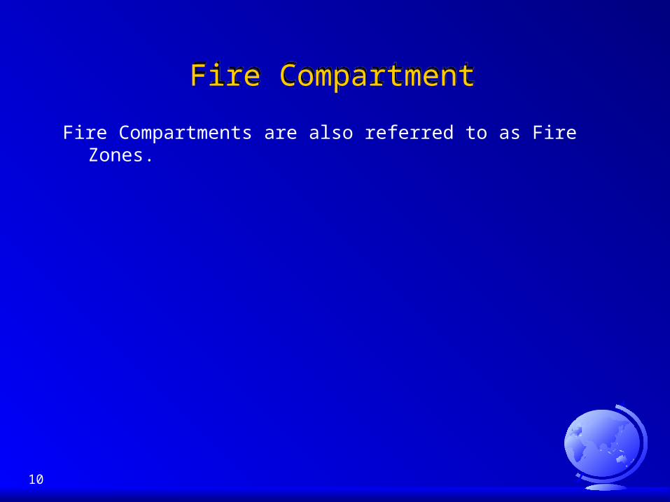
Fire CompartmentFire Compartment
Fire Compartments are also referred to as Fire Zones.

11
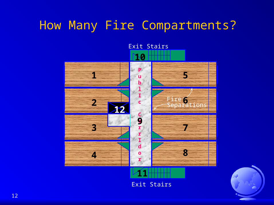
Explanation of Fire CompartmentsExplanation of Fire Compartments
Fire compartments are a series of “fireproof” boxes created during the construction process. Each box is separated from the others by fire separations and will contain a fully engulfed fire (1800º - 2000º F) for a known period of time.
Fire compartments normally have 6 or more sides: (4) walls (vertical fire assemblies) and (1) ceiling and (1) floor (horizontal fire assemblies).
Each of these walls and floor/ceiling fire assemblies are known as individual fire separations.
Fire separations are constructed using materials that have known fire erosion time/temperature/pressure ratings.
I.e..: concrete, concrete block and membrane type materials (GWB with metal, wood studs) etc....
12
How Many Fire Compartments?
Exit Stairs
Exit Stairs
PublIc
CorrIdor
FireSeparations
1
2
3
4
5
6
7
8
9
10
11
12

13
WHAT IS THE INTENT
OF THE BUILDING CODE? to maximize life safety and
minimize property damage. accomplished by
constructing buildings that contain fire and smoke within fire compartments.
The UBC is primarily a health and safety document.
14
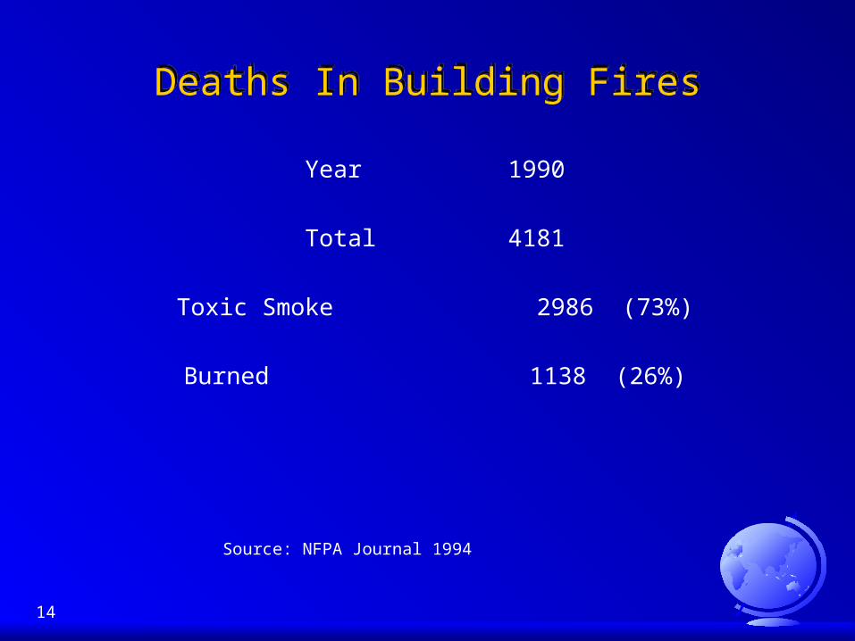
Deaths In Building FiresDeaths In Building Fires
Year 1990
Total 4181
Toxic Smoke 2986 (73%)
Burned 1138 (26%)
Source: NFPA Journal 1994

15
Smoke ManagementSmoke Management
Smoke travels up to 50 feet per minute in a developing fire
300 feet per minute in a fully engaged fire.
All fire separations must stop the spread of
SMOKE AND FIRE
Life Safety

16
Regulated Construction ProductsRegulated Construction Products
In the United States, all passive fire protection products are classified as regulated construction products. This is a mandatory requirement.
Products must be tested to the requirements of the recognized standard by an Accredited Third Party Testing Agencies in order to comply with the Uniform Building Code.
Third part testing gives Further Assurance that products will perform to their tested and listed uses.
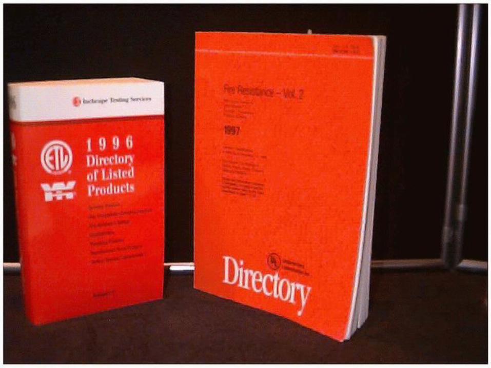
Always refer to Fire Resistance Directories.

17
Noncombustible ConstructionNoncombustible Construction
Many buildings are constructed as Noncombustible under the Uniform Building Code
Most government buildings as follows: Hospitals and Health Care Universities and schools Federal and state prisons Hydro projects and nuclear power plants
Most new Federal Government specifications call for firestop and smoke seals to be installed around all penetrating items as well as smoke seals anywhere dissimilar fire separations meet. (i.e... GWB to concrete floor/ceiling assemblies.)

18
Test Methods & StandardsTest Methods & Standards
ASTM E-119Standard Method of Fire Endurance Tests of Building
Construction Materials
ASTM E-84Standard Method of Testing for Surface Burning Characteristics
of Building Materials and Assemblies
ASTM E-136Standard Method of test for determination of Non-combustibility in
Building Materials
ASTM E-814
Standard Method of Fire Tests of Firestop Systems

19
Fire Separations are SacrificialFire Separations are Sacrificial
Fire separations are sacrificial in a fire condition. The cross section of each type has a known fire erosion (BURN THROUGH) time.
The fire separation cannot conduct heat for the rating period over 2500 F to the non fire exposed side.
20
Accredited Fire Resistance Testing Labs
Accredited Fire Resistance Testing Labs
Each testing agency must obtain accreditation for their individual specialties from the Code Body Authority.
Accredited fire resistance laboratories are;– Underwriters Laboratories– Warnock Hersey (Intertek)– Omega Point– Southwest Labs
Each of these agencies have there own individual marks (logos)
21
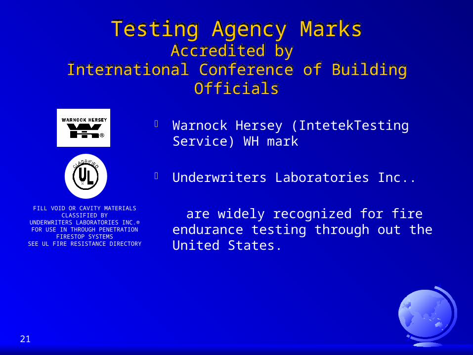
Testing Agency MarksAccredited by
International Conference of Building Officials
Testing Agency MarksAccredited by
International Conference of Building Officials
Warnock Hersey (IntetekTesting Service) WH mark
Underwriters Laboratories Inc..
are widely recognized for fire endurance testing through out the United States.
FILL VOID OR CAVITY MATERIALSCLASSIFIED BY
UNDERWRITERS LABORATORIES INC.®FOR USE IN THROUGH PENETRATION
FIRESTOP SYSTEMSSEE UL FIRE RESISTANCE DIRECTORY

22
ASTM E-814 Standard Method of Fire Tests of Firestop Systems
UL 1479Fire Tests For Through-Penetration Firestops
UL 2079Tests For Fire Resistance Of Building Joint Systems
Dynamic Movement of Construction Joints.
ASTM E-814 Standard Method of Fire Tests of Firestop Systems
UL 1479Fire Tests For Through-Penetration Firestops
UL 2079Tests For Fire Resistance Of Building Joint Systems
Dynamic Movement of Construction Joints.

23
The Standards and Test MethodsThe Standards and Test Methods
Standards and test methods for regulated construction products are based on
MINIMUM ACCEPTABLE STANDARDS

24
Where to Firestop and Smoke Seal?
Service Penetrations Where a fire separation has been penetrated for services, a
firestop system is installed in the annular space around the penetrating item OR in an open void if a penetrating item is not present.
Construction/Expansion Joints Where fire separations meet, a firestop system is installed in the
joint or void (i.e.. concrete slabs to curtain wall assemblies or GWB fire separations to dissimilar surfaces).
Fire Blocking Where hollow cavity fire separations and open interior cavity or
ceiling space will transverse into another fire compartment.

25
•ACCEPTED/RECOGNIZED
THIRD PARTY TESTING LABS IN CANADA
•ACCEPTED/RECOGNIZED
THIRD PARTY TESTING LABS IN CANADA
ULC UNDERWRITERS LABORATORIES CANADA
W/H INTERTEK WARNOCK HERSEY
cUL UNDERWRITERS LABORATORIES INC.
( tested to the Canadian Standard CAN4 S115)

26
27
28
The “MARK” & Product Labeling The “MARK” & Product Labeling
Assemblies are tested and listed Not the product.
The product with the Mark on the label was tested in a system assembly
29
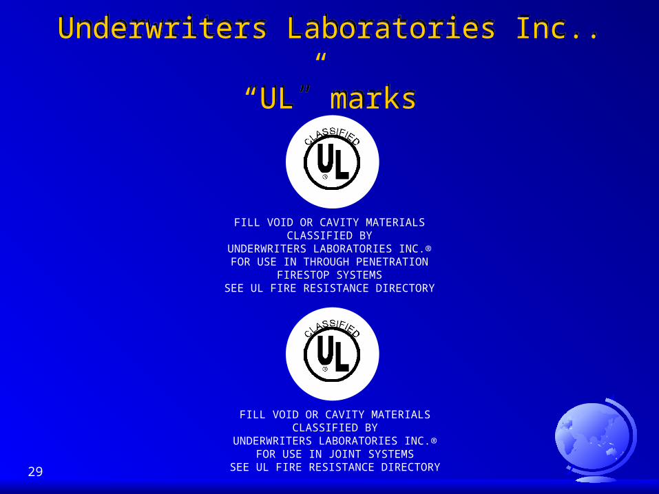
Underwriters Laboratories Inc.. “UL” marks
Underwriters Laboratories Inc.. “UL” marks
FILL VOID OR CAVITY MATERIALSCLASSIFIED BY
UNDERWRITERS LABORATORIES INC.®FOR USE IN THROUGH PENETRATION
FIRESTOP SYSTEMSSEE UL FIRE RESISTANCE DIRECTORY
FILL VOID OR CAVITY MATERIALSCLASSIFIED BY
UNDERWRITERS LABORATORIES INC.®FOR USE IN JOINT SYSTEMS
SEE UL FIRE RESISTANCE DIRECTORY
30
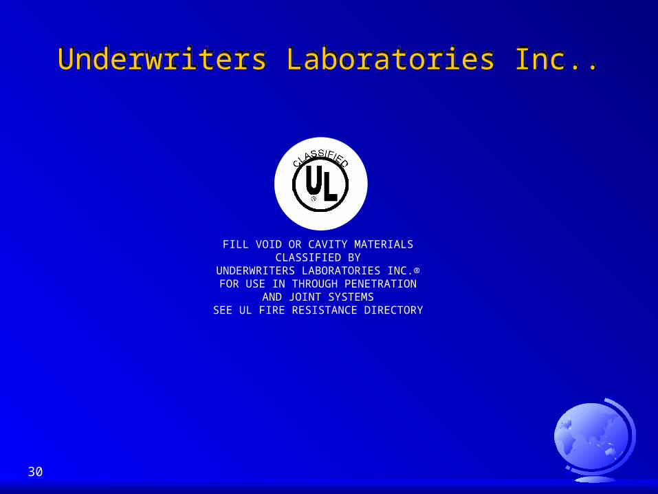
Underwriters Laboratories Inc..Underwriters Laboratories Inc..
FILL VOID OR CAVITY MATERIALSCLASSIFIED BY
UNDERWRITERS LABORATORIES INC.®FOR USE IN THROUGH PENETRATION
AND JOINT SYSTEMSSEE UL FIRE RESISTANCE DIRECTORY

31
Warnock Hersey (WHI mark)Warnock Hersey (WHI mark)
WHI has many testing facilities throughout the United States several dedicated to fire endurance testing.
Warnock Hersey tests to the ASTM E-814 standard (ICBO, UBC, BOCA, AND SBCII)
ASTM E-814 requires positive pressure testing for firestop assemblies.

32
FOLLOW UP INSPECTION SERVICESFOLLOW UP INSPECTION SERVICES
UL conducts 4 follow up inspections each year on any manufacturer listed in their Fire Resistive Directory
Intertek Warnock Hersey has the same follow up inspection policy
Inspections are done each quarter Inspections are done at random Materials and Procedures must be identical to the previous
inspection or you must re test Manufacturers who give a Report Number, not a Listed Systems
Design Number, are not included in the Follow - Up Inspection Program ( a “Buyer Beware” attitude should taken )

33
CHANGES TO FIRESTOP STANDARD UL 1479 UL 2079 and ASTM E-814 CHANGES TO FIRESTOP STANDARD UL 1479 UL 2079 and ASTM E-814
Changes are coming
Testing Standards, Methods
Product Testing Requirements (i.e.. aging tests will be conducted before subjected to Firestop Tests) Will these products last the life expectancy of the building

34
FIRE RESISTIVE RATINGFIRE RESISTIVE RATING
The time in hours that a material or assembly will withstand the passage of flame and the transmission of heat when exposed to fire under specified test conditions and performance criteria

35
538º C 1000º F
843º C 1550º F
927º C 1700º F
1010º C 1850º F
1052º C 1925º F
1093º C 2000º F
What Temperatures Are Fire Compartments Tested to
Withstand?
All ASTM E-119 fire separations and ASTM E-814 firestop systems are tested to this time/temperature curve.
5 min.
30 min.
1 hour
2 hours
3 hours
4 hours
36
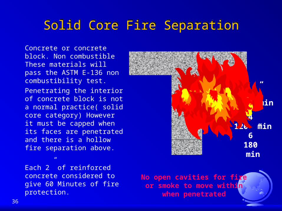
Solid Core Fire SeparationSolid Core Fire Separation
Concrete or concrete block. Non combustible These materials will pass the ASTM E-136 non combustibility test.
Penetrating the interior of concrete block is not a normal practice( solid core category) However it must be capped when its faces are penetrated and there is a hollow fire separation above.
Each 2” of reinforced concrete considered to give 60 Minutes of fire protection.
2” 60 min
4”120 min
6”180 min
No open cavities for fire or smoke to move within when penetrated

37
This type has interior framing members with an exterior skin of single or multiple layers of GWB or other materials which have a known burn through rating period. Hollow core fire separation are sacrificial.
Each layer of type “X” 5/8” (15mm) will give 30 minutes of fire protection.
Particular attention has to be paid to header and sill plate penetrations. Fire and smoke cannot be allowed access to the interior of the fire separations above or below.
Hollow Core Fire Separations
Layer 1, 30 min
Layer 2, 60 min Fire inside cavity, 60 min
Through headerpenetrationsinto hollow floor/ceiling
fire separationat 60 Min
120 Min
Layer 3, 90 min
Layer 4, 120 minEntire separation failure

38
Fire TapeFire Tape
Fire tape is not an acceptable firestop, smoke stop or draft stop
Proper treatment of joints that meet dissimilar surfaces, GWB to concrete assemblies, requires an elastomeric firestop systems in order to allow for the slab above flexing under load. All rigid materials fail this requirement.
Fire Tape
Fire tape lasts approximately
8 min before failure8 min
Right

39
Smoke SealSmoke Seal Limits to Smoke Movement - Every building shall be designed to
limit the danger to occupants and fire fighters from exposure to smoke in a building fire.
When considering a smoke seal in or around the perimeter of fire separations the sealant should be able to withstand the time / temperature curve of the fire separation and overall fire compartment. (1800º - 2000º F)
Smoke seals should be a mandatory requirement of the building code for all high occupancy buildings.

40
EarthquakesEarthquakes Seismic restraint (earthquake vibration control) is one of the fastest
growing fields in North America Firestopping is following at the same pace. The major concern of earthquakes is broken and sheared off gas
and electrical lines which can create fires. It is critical to allow for the movement of all items penetrating fire
separations. NFPA 13 states that all sprinkler pipes passing through fire
separations require a minimum 1” (25mm) annular space around the sprinkler pipe and must be sealed with a flexible firestop material.
Many States have adopted the guidelines of NFPA 13 with the exception that the flexible firestop material must conform to ASTM E-814 in order to maintain the integrity of the fire separation.

41
The Importance of Listed Systems Designs
The Importance of Listed Systems Designs
Think of a listed systems design as the “License” or “Certificate of Worthiness” allowing a firestop manufacturer to sell product for the exact application as outlined in the systems design.
If a product does not have a third party listed systems design
TO COVER A SPECIFIC APPLICATIONthe product cannot be used for that application, no
matter how many listings it has for other uses. The listing also provides a trail of liability to the listing agency
and the manufacturer. If you have installed or passed an application without a listing
you have just accepted all liability associated with an improper installation.
42
How To Read Systems DesignsHow To Read Systems Designs
It is important to be able to read and understand systems designs.

43
The “F” (Fire) RatingThe “F” (Fire) Rating
10.1.1 A firestop system shall be considered as meeting the requirements for an “F” rating if it remains in the opening during the fire test and hose stream test within the following limitations.
10.1.2 The fire stop shall have withstood the fire test for the rating period without permitting the passage of flame through openings, or the occurrence of flaming on any element of the unexposed side of the fire stops.
10.1.3 During the hose stream test, the fire stop shall not develop any opening that would permit a projection of water from the stream beyond the unexposed side.
(Ref: ASTM E 814, 10.1.1 to 10.1.1.3)
44
How Important is the “T” RatingHow Important is the “T” Rating The “T” rating is the evaluated time it takes for the heat to be
conducted through the penetrating item and the fire separation and ignites combustible items on the non fire exposed side.
When penetrating into a hollow fire separation that has combustible framing members (wood) the “T” rating is extremely important.
Many firestop manufacturers test the penetrating item centered between the studs. Very few manufacturers can provide truly representative listing details for the penetrating item attached to the studs and/or penetrating the header or sill plates in wood framed construction.

45
The “FT” (Fire and Temperature) RatingThe “FT” (Fire and Temperature) Rating
The firestop system must pass the requirements of the “F” rating, AND
10.2.1.1 The transmission of heat through the fire stop during the rating period shall not have been such as to raise the temperature of any thermocouple on the unexposed surface of the fire stop or on any penetrating item more than 325º F (181º C) above its initial temperature. Also the fire stop shall have withstood the fire test during the rating period without permitting the passage of flame through openings, or the occurrence of flaming on any element of the unexposed side of the fire stops.
(Ref: ASTM E 814, 10.2.1.1)

46
Understanding the RatingsUnderstanding the Ratings
The “F” rating is simple: No fire on the “unexposed” side and shall not develop any opening that would permit a projection of water from the hose stream test beyond the “unexposed” side.
There are 2 ways to obtain the hose stream requirement. The first is to build two identical assemblies, burn the first one for the full “F” rating period, burn the second one for 1/2 the “F” rating period and perform the hose stream on that assembly. If you are confident in your firestop system, build one assembly, burn it for the full “F” rating period and hose stream that assembly. Passive Fire Protection Partners. uses the one assembly approach on it’s firestop tests.

47
Understanding the Ratings (cont)Understanding the Ratings (cont) The “FT” rating is a little more difficult. The firestop system
must pass the requirements of the “F” rating AND the thermocouple on the fire stop or penetrating item penetrating from the “unexposed” side of the furnace cannot exceed more than 325º F (181º C) above its initial temperature.
The International Standards Organization (ISO) takes a real conditions approach. Instead of an thermocouple evaluation approach to this test, they place a cotton swab on the item penetrating on the “unexposed” side of the assembly. When the heat of the penetrating item cause the cotton to ignite, is the stated time in minutes that you fail the requirements of the “T” rating. The CAN/4 S101 full scale test also uses this approach. (ref: CAN/4 S101 7.3.2.)
The most difficult rating to obtain is the “FT” in fire separations.

48
PENETRATINGITEM / PIPE
max
min
HOLE
ANNULAR SPACE(ANNULUS)
Maximum Annular SpaceMaximum distance between
substrate and pipe
Minimum Annular SpaceMinimum distance between
substrate and pipe(pipe cannot touch substrate unless specified)

49
Annular Space(the Firestop Manufacturer’s nightmare)
Annular Space(the Firestop Manufacturer’s nightmare)
The greater the annular space the greater the erosion rate of the firestop system.
Erosion cycles in small annular spaces are extremely restricted.
In concrete types, the concrete dissipates a lot or the furnace heat.
The smaller the annular space the easier to pass the test requirements.
Annular space is one of the most important listed systems design criteria.
When it says MAXIMUM annular space that is precisely what it means.

50
Centered in the HoleCentered in the Hole
If the Listed System Design defines the penetrating item as centered in the hole, do I have the proper systems design that Underwriters Laboratories or Warnock Hersey will recognize when the penetrating item is offset in the hole.
NO
You can verify this by calling the listing agency

51
Exposed / UnexposedExposed / Unexposed
Fire tests refer to the fire “exposed” or “unexposed” side of a test assembly:
- Horizontal assemblies: Fire usually burns in an upward direction The fire exposed side of a horizontal separation would be the interior ceiling. The “unexposed” side of this separation would be the floor of the compartment above.
- Vertical separations: both sides of a vertical separation are potentially the fire “exposed” side.

52
Perform the TestPerform the Test
Passive Fire Protection Partners. has its own firestop testing furnace certified under a Third Party Testing Agencies Witness Program.
These furnaces have been built and are calibrated regularly under the same terms as the testing agencies furnaces and will perform to all the requirement of the standard.
If no listing exists, these furnaces can usually be used on short notice to perform any firestop and construction materials configuration desired. This allows for proven results rather than any guess work.
Passive Fire Protection Partners. furnace is capable of testing floor/ceiling and wall firestop assemblies simultaneously.

53
Firestop Systems ReportFirestop Systems Report Firestop System Report: results reported in accordance with the
performance in the tests prescribed in the ASTM E-814 methods. Express the results in time periods of resistance to passage of flame to the nearest integral minute. Reports shall include the following:
Description of assembly and materials; identify and describe items of the test fire stop. Drawings depicting geometry, exact size (length-width-thickness) and location of firestop systems within the test assembly.
Relative humidity of the fire test sample
Unexposed side temperatures for the duration of the standard fire test.
The “F” and “T” ratings for each fire stop in the time period of resistance.
The location of the pressure probes and the differential pressures between the exposed and unexposed surfaces of the test assembly measured during the fire test.
(Ref, ASTM E-814, 11.1-11.5 )

54
“T” rating Cont..“T” rating Cont..
Copper VS Plastic "T" Rating
0.00
200.00
400.00
600.00
800.00
1000.00
1200.00
1400.00
1600.00
1800.000 6 12 18 24 30 36 42 48 54 60
Time (minutes)
Tem
per
atu
re (
F)
This table is information taken from an actual 1 hour GWB firestop test. It is important to note that the copper pipe follows the time/temperature curve of the furnace and failed the “T” rating at 38 min. This time varies from 12 to 40 minutes depending on the assembly type and thickness and penetrating material types of the firestop system.
The plastic pipe stayed at around 107 F throughout the test easily passing the “T” rating criteria.
Furnace Temperature“T” Fail LineCopper PipePlastic Pipe

55
“T” RATINGPenetrating Item Conductivity
The previous slide demonstrated copper vs. plastic, all metallic pipe depending on conductivity will follow the time/temperature curve of the furnace.
Non-combustible Pipe (metallic) does not normally pass the “T” Rating requirements.
Combustible Pipe (plastic), because of it’s very poor conductivity, and it usually burning off with the firestop sealing the hole normally passes the “T” Rating.

56
Are the ratings separableAre the ratings separable
No If just an “F” rating is asked for, that is all that is required.
If an “FT” is asked for you must pass all the criteria for the full rating period.
Many systems have 2 hour “F” ratings and 10-20 minute “T” ratings. This means the overall systems “FT” rating is 10-20 minutes not 2 hours.

57
Service PenetrationsService Penetrations
There are two main types of Service penetrations:
Closed Penetrating Items
Open Penetrating Items

58
Closed Penetrating ItemClosed Penetrating Item The interior of a closed penetrating item is not open or vented to
atmosphere anywhere within the system: process and supply piping systems or solid items like electrical wire, solid steel beams or seismic braces, etc... There are two classifications in this category:
Combustible
Plastics or materials that will melt prior to 1800º - 2000º F. These systems are capped or closed on both sides during firestop testing with a small vent hole on the “unexposed” side.
Non-combustible
Metallic or materials that will withstand 1800º F and above. Aluminum for these purposes is considered to be combustible. These systems are capped or closed on the fire “exposed” side (furnace side) during firestop testing.

59
Open Penetrating ItemsOpen Penetrating Items Open penetrating items are exactly that: open or vented to
atmosphere. The same two basic classifications exist for this category:
Combustible
– Plastics or materials that will melt prior to 1800º -2000º F. These systems are only capped on fire “exposed” side.
Non-Combustible– Metallic or materials that will withstand 1800º F and above.
Aluminum for these purposes is considered to be combustible. These systems are also only capped on the fire “exposed” side.
Again, the test furnace for Firestop testing has no way to differentiate between combustible or non-combustible systems. For a combustible or non-combustible system to pass, it must not permit the passage of flame through openings, or the occurrence of flaming on any element of the “unexposed” side of the firestop system.

60
Firestop Materials (Components)
Firestop Materials (Components)
A firestop system is composed of one or more materials. The listed system design identifies the exact materials to
be installed
Single Component - a firestop system using only ONE Listed Material (filler material maybe optional)
Multiple Component - a system using more than one material. These systems must be installed using the filler material at the correct density and depth. The filler material is usually stopping the fire.

61
Firestop Materials (cont)Multiple Component Systems
SEALANT the smoke and hot gases seal.
adheres the filler material in place during building settling and seismic movement and assists during the hose stream rating.
FILLER (ceramic fibre, mineral/rock wool, gypsum wall board) the filler stops or slows down the fire and high temperature from
getting to the sealant.

62
Firestop Materials (cont)Single Component Systems
Firestop Materials (cont)Single Component Systems
There are two types of single component firestop products:
RIGID and ELASTOMERIC
1. RIGID FIRESTOPS The 1960’s to the early 80’s. Concrete, cementitious
grouts, gypsum filler compounds, etc.. These systems / products do not allow for dynamic or building movement.
Building settling or dynamic movement cause cracking around the penetrating item, the firestops can fall out entirely, smoke seals are non existent

63
Firestop Materials (cont)Single Component Systems
Firestop Materials (cont)Single Component Systems
2. ELASTOMERIC (flexible caulks and sealants)
– Technological advancements have produced much more sophisticated firestop material. Earlier material required a lot of sealant to be installed, restricting movement and requiring small annular space
– Recently developed elastomers allow maximum movement, large annular spaces, offset designs, easy application.
– They will pass the requirements of ASTM E-814 (firestop test) and also the ASTM E-136 (non-combustibility test).

64
Service PenetrationMultiple Component Firestop System
(Solid Horizontal Fire Separations)
Plan View
1) Penetrating Item2) Substrate Assembly Type3) Component 1, Firestop Sealant4) Component 2, Mineral wool or Ceramic fiber
3
41
2
Fire exposed side

65
Service PenetrationMultiple Component Firestop System
(Solid Vertical Fire Separations)
Side View
1) Penetrating Item2) Substrate Assembly Type3) Component 1, Firestop Sealant4) Component 2, Mineral wool or Ceramic fiber
Note: Vertical separations,both sides of the wall are considered the fire
exposed side
Cutaway View
3
4
1
2
3

66
3
1
2 Cutaway View
Service PenetrationSingle Component Firestop System
(Solid Horizontal and Vertical Fire Separations)
67
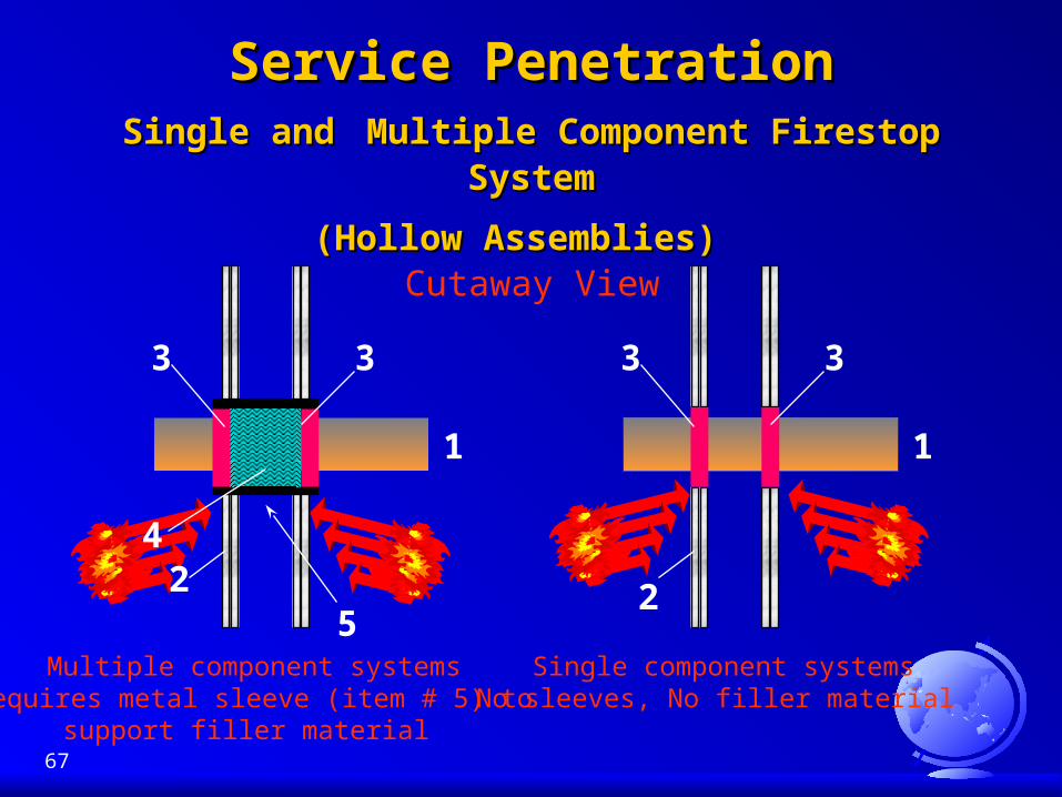
Service PenetrationService PenetrationSingle andSingle and Multiple Component Firestop Multiple Component Firestop
SystemSystem
(Hollow Assemblies)(Hollow Assemblies) Cutaway View
Single component systemsNo sleeves, No filler material
3
4
1
2
3
5Multiple component systems
requires metal sleeve (item # 5) tosupport filler material
3
1
2
3

68
Service PenetrationService PenetrationSingle Component Firestop SystemSingle Component Firestop System
(Hollow Assembly Interior Penetrations )(Hollow Assembly Interior Penetrations )
Header and Sillpenetration, andpenetration of
the faces
1
3
Header and Sillpenetration, No penetration of
the faces
2
1) Penetrating Item 2) Substrate Assembly Type3) Component 1, Firestop Sealant4) Component 2, Optional
69
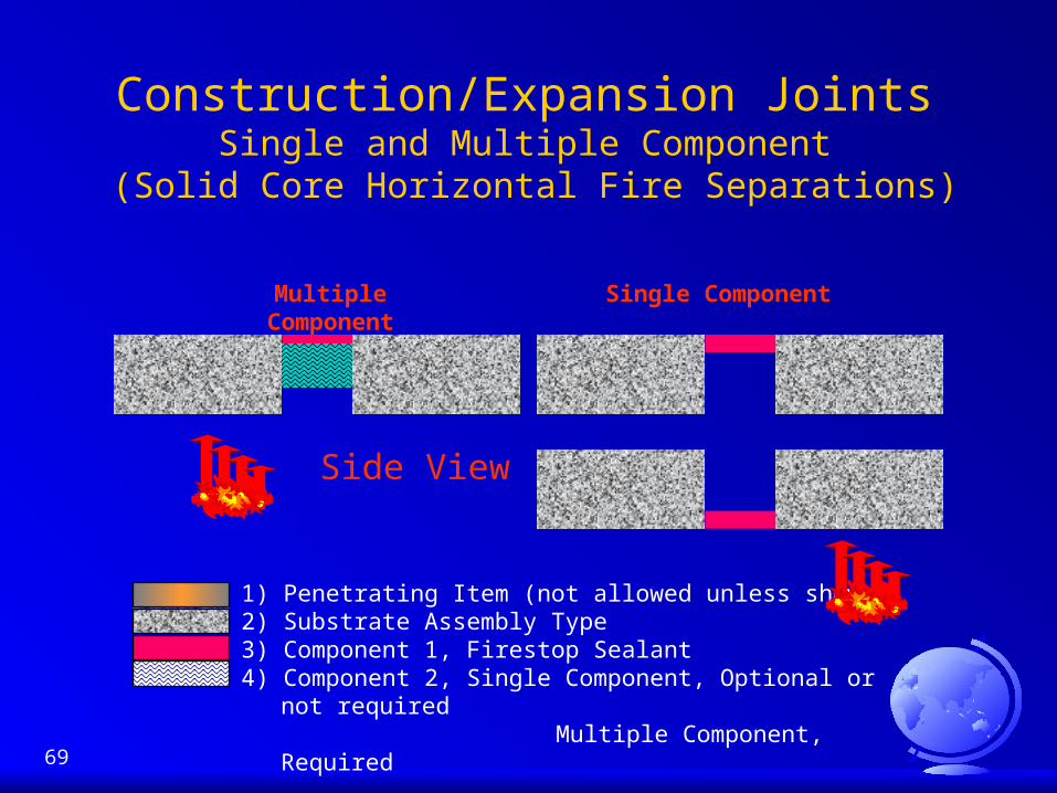
Construction/Expansion JointsSingle and Multiple Component
(Solid Core Horizontal Fire Separations)
Multiple Component
Side View
Single Component
1) Penetrating Item (not allowed unless shown)2) Substrate Assembly Type3) Component 1, Firestop Sealant4) Component 2, Single Component, Optional or not required
Multiple Component, Required

70
Firestop Materials are SacrificialFirestop Materials are Sacrificial
Each firestop system has a known fire erosion rating or burn through time.

71
Industry Firestop Sealants Typical Vehicle Service Temperatures
Industry Firestop Sealants Typical Vehicle Service Temperatures
1350º F 15 MinASTM E-136 Non-Combustible Classification
1832º F1, 2 or 3Hours
ASTM E-814 Firestops and ASTM E-119 Fire Separations
Latex Polymer 325º F
Urethane Urethane Polymer 425º F
Silicone Polymer 550º F
Latex
Silicone

72
Insulation/Filler MaterialsFiberglass Insulation
Insulation/Filler MaterialsFiberglass Insulation
Fiberglass insulation does not meet the average test requirements of 1832F. This material is rarely listed as the filler material component of a firestop system. Some manufacturers have obtained rating for fiberglass pipe insulation, usually the sealant component is an intumescent that when the insulation melts will fill any open cavities.
Use mineral wool pipe insulation at the fire separation.
1382º F 15 MinASTM E-136 Non-Combustible Classification1832 F1,2 or 3Hours
ASTM E-814 Firestops and ASTM E-119 Fire Separations
850º FFiberglass
73
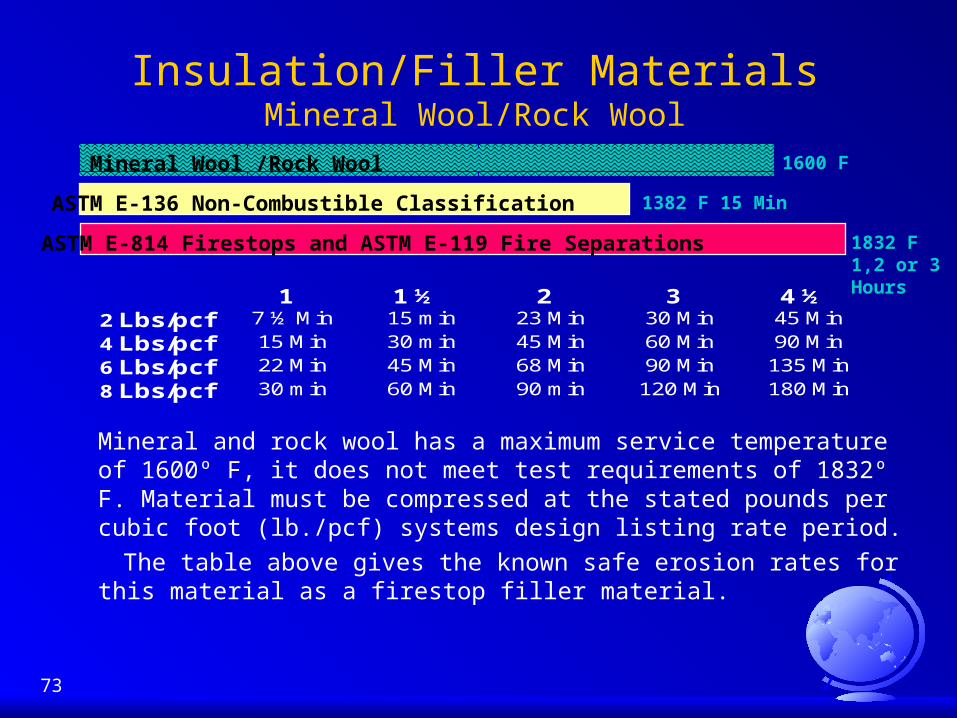
Insulation/Filler MaterialsMineral Wool/Rock Wool
Mineral and rock wool has a maximum service temperature of 1600º F, it does not meet test requirements of 1832º F. Material must be compressed at the stated pounds per cubic foot (lb./pcf) systems design listing rate period.
The table above gives the known safe erosion rates for this material as a firestop filler material.
1” 1 ½” 2” 3” 4 ½”2 Lbs/pcf 7 ½ Min 15 min 23 Min 30 Min 45 Min
4 Lbs/pcf 15 Min 30 min 45 Min 60 Min 90 Min
6 Lbs/pcf 22 Min 45 Min 68 Min 90 Min 135 Min
8 Lbs/pcf 30 min 60 Min 90 min 120 Min 180 Min
1382 F 15 MinASTM E-136 Non-Combustible Classification
1832 F1,2 or 3 Hours
ASTM E-814 Firestops and ASTM E-119 Fire Separations
1600 FMineral Wool /Rock Wool
74
Insulation/Filler MaterialsCeramic Fiber/Aluminum SilicateInsulation/Filler MaterialsCeramic Fiber/Aluminum Silicate
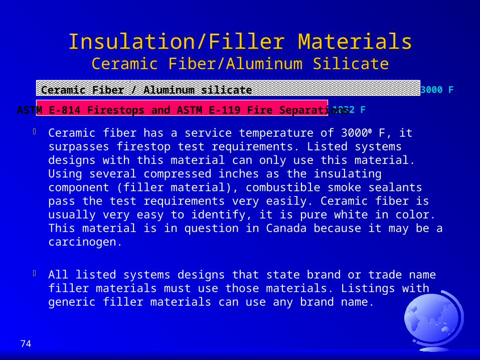
Ceramic fiber has a service temperature of 30000 F, it surpasses firestop test requirements. Listed systems designs with this material can only use this material. Using several compressed inches as the insulating component (filler material), combustible smoke sealants pass the test requirements very easily. Ceramic fiber is usually very easy to identify, it is pure white in color. This material is in question in Canada because it may be a carcinogen.
All listed systems designs that state brand or trade name filler materials must use those materials. Listings with generic filler materials can use any brand name.
1832 FASTM E-814 Firestops and ASTM E-119 Fire Separations
3000 FCeramic Fiber / Aluminum silicate

75
Things to Remember AboutFirestop Sealants
Things to Remember AboutFirestop Sealants
Most sealants labeled firestop are actually “Smoke” sealants, for use only as part of a multi-component firestop system.
Firestop sealants are NOT GENERIC. Each manufacturer has a proprietary formula that has been third party tested. You cannot substitute one sealant for another!
Check for chemical compatibility with different substrates and penetrating items.
Check for adhesion capability Confirm adhesion capability to “actual” job site conditions of
damp, dirty or oily surfaces. Confirm elasticity to withstand building settling and penetrating
item movement.
76
INTUMESCENTSINTUMESCENTS
What is an INTUMESCENT Material That Expands When Exposed To High Heat 450 Deg. F ( some are 2 Stages ) Caulks, Wrap Strips, Devices (Collars), Boards Uses : Plastic Pipe, Insulated Pipe Telescoping Caution: May Have Long Term Aging Problems
Small Annular Space ( 1/4 inch )
NFPA 13 Requires Movement

77
Joints, what StandardJoints, what Standard ICBO adopted the UL 2079 testing method for dynamic testing
of fire rated expansion and control joints. All joints to be cycled a minimum of 20 times from full compression to full expansion. The joint is then fire tested in its fully expanded state. All joints must meet the “FT” rating.
Minimum joint testing dimension ratio is 10 to 1. A 4” joint in order to be representative requires a 40”long assembly to be tested (pilot scale furnace). A 12” joint requires 120” in length (full scale furnace)
Many construction projects continue to install rigid sprayed on cementitious materials or gypsum compounds where dynamic movement will occur i.e. top of wall and edge of slab

78

79
Acceptance Criteria For Joints Systems
Acceptance Criteria For Joints Systems
1. Introduction 1.1 Scope: These criteria establish minimum requirements
for recognition of fire-resistive joint systems in ICBO ES evaluation reports under Section 706 of Chapter 7 of the Uniform Building CodeTM.
1.2 Reference Documents:
1. 1994 Uniform Building CodeTM .
2. UL Standard 2079, Tests for Fire Resistance of
Building Joint Systems,”

80
UL Standard 2079 Joint Movement Revised
UL Standard 2079 Joint Movement Revised
Joint Systems designed to accommodate movement shall be preconditioned by cycling between the minimum and the maximum joint opening width for which they are intended to function for the number of cycles specified in the following table
TYPE OF JOINT SYSTEM NUMBER OF CYCLES– Expansion/Contraction 500– Seismic 100– Wind Sway 500
81
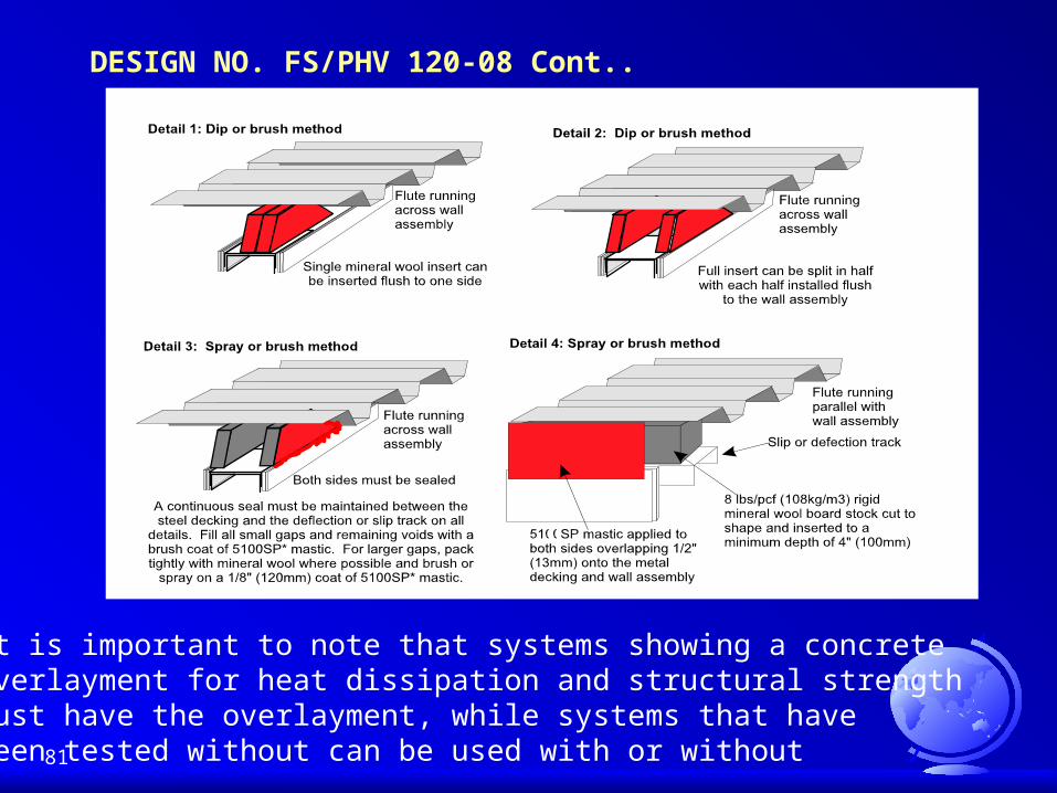
It is important to note that systems showing a concreteoverlayment for heat dissipation and structural strengthmust have the overlayment, while systems that havebeen tested without can be used with or without
DESIGN NO. FS/PHV 120-08 Cont..

82
LISTED SYSTEMS DESIGNLISTED SYSTEMS DESIGN
Manufacturer submits an assembly containing their firestopping products to a accredited testing agency to be tested to the current firestop standard
A report is written and given to the manufacturer / customer whether the test was sccessful or not. This report is confidential information between client and testing agency
If the test was successful a listing is promulgated by the testing agency and is published in the Fire Resistive Directory. This outlines the information relavent to the test standard and is used for the submittal package
Although these Listings are commonly referred to as “APPROVALS” they are not. They are like report cards

83

84
Tested Systems / EvaluationsTested Systems / Evaluations
When a tested and listed systems designs exists for a firestop procedure, this is the system that should be installed
When a systems design cannot be found, an evaluation can be made by an accredited testing agency that has experience in firestop testing.
If the testing agency will not evaluate a proposed design, a full firestop test must be performed.
Engineering judgments or evaluations by firestop manufacturers can be accepted by the architect or AHJ as long as they know it is a judgment and no tests exists for the application

85
Engineered Judgment By Third Party Testing Agency
Engineered Judgment By Third Party Testing Agency
i.e. UL and Interteck Warnock Hersey
Judgment is given from known data in previous tests and should reference a current Listed System.

86
Manufacturer Letter Of JudgmentManufacturer Letter Of Judgment
AHJ AND ARCHITECT
MAY OR MAY NOT ACCEPT
BE CAREFUL!

87
Evaluations Engineered JudgmentsEvaluations Engineered Judgments
Evaluations are the accurate results reported from the actual firestop test that clearly outline all the items used to create the firestop system including conduits, pipes, cables, jacket types, sizes, percent fills, required supports and construction types. Evaluations can only be performed by an accredited testing agency.
Engineering Judgments are extrapolations of data from actual firestop tests to encompass oversized items or different construction configuration types that were not tested but may possibly work in the opinion of the accredited testing agency.

88
MANUFACTURE’S LETTER OF JUDGMENT
MANUFACTURE’S LETTER OF JUDGMENT
Engineered Judgments given by a manufacturer when a tested and listed system does not exist
AHJ’S should be cautious when these are offered by a manufacturer
Submitting Letters of Judgments is being abused
Should always refer to a tested and listed system conducted by a Third Party Testing Lab

89

90
Building InspectorsOn-Site Check List
1. Always request the Listed System Design (cut sheet) for each application from the contractor. The System Design must be from the current UL or WH fire resistance directory or have a accompanying recent test letter from the Accredited Third Party Testing Agency.
2. Check that each System Design meets each jobsite application condition.
3. Is mineral wool or ceramic fibre required, what density?
4. What firestop product(s) is the contractor using? Is there a “WH” or “UL” logo and identification on the product?

91
What to look for in the listingWhat to look for in the listing Is the construction type (substrate materials) listed. Does the design allow for penetrating horizontal and vertical
fire separations. Is the penetrating item size and material type listed. Does the design allow for combustible (plastic) or non-
combustible (metallic) pipe systems. Is the design for open (DWV) or closed (process and supply)
systems or both. Is the design calling for the penetrating item to be centered or
can it be offset. What is the maximum allowable annular space. Does the detail show penetrating header and sill plates in
wood framed construction.
92
The Insurance Company ViewThe Insurance Company View
Insurance Underwriters and Risk Management Groups have based their insurance premiums for multi-tenant and commercial buildings constructed since 1985 on the assumption that they have complied with the Building Code.
Some Insurance Companies Risk Management groups are now performing their own passive fire protection inspections.
Some Building Owners are refused insurance or are required to pay a higher premium for their building even though it was constructed after 1985.

93
The IBM Tower, MontrealThe IBM Tower, Montreal
This 66 story high-rise was built after 1985. Though mandated by the NBC in Canada, no
firestopping was installed on the curtain wall system or in the service penetrations.
94
Internet ResourcesInternet Resources
the best tools for fire related resources and data bases available anywhere are on the Internet.
Many Architects, Building Officials and Fire related organizations are already using the Internet to receive and post up to the minute news for their respective professions or service from all over the world.

95
To Log onTo Log on
Passive Fire Protection Partners. world wide web site is located at:
http://www.firestop.com