上海师范大学电气信息系 chapter 3 lightwave fundamentals....
TRANSCRIPT

上海师范大学电气信息系
Chapter 3
Lightwave Fundamentals

上海师范大学电气信息系
Contents
Reflection at a plane boundary
Resonant cavities
Polarization
Dispersion, pulse distortion, information rate
Electromagnetic waves
Critical-angle reflection
上海师范大学电气信息系
3.1 Electromagnetic Waves
Wave Properties
•velocity
•power
•polarization
•interference
•refraction

上海师范大学电气信息系
Wave traveling in the z direction
On the figure, t1 < t2 < t3
t1 t3t2
Electric Field
Position (z)
Electric field:
At t1 < t2 < t3 , peak amplitude E0 is fixed, Ф = wt - kz
(3.1)
Electromagnetic Waves

上海师范大学电气信息系
This is a solution of the wave equation:2 2
22
2
0
0
E k E
EE
z v
(3.2)Propagation factor:
Frequency: f = v/
Radian frequency: = 2f (rad/s)
Wave peak amplitude: E0
Wave phase: = t-kz
kv
Electromagnetic Waves

上海师范大学电气信息系
Relationships for the Propagation Factor k
k = /v = /(c/n) = n/c
In free space, n = 1, so that k = ko = /c
In general, then k = kon
o
c
f
(3.6)
o: wavelength in free space
: wavelength in the medium
/o n (3.7)
2 2k
vv
f
/ ov c n
f f n
Then,
f is fixed, f = f0
Electromagnetic Waves

上海师范大学电气信息系
Power in a resistor: Pr = V2/R
Power is proportional to the voltage (V) squared.
In an optical beam, define Intensity: I = E2
Since P E∝ 2, P ∝ I.
Power
上海师范大学电气信息系
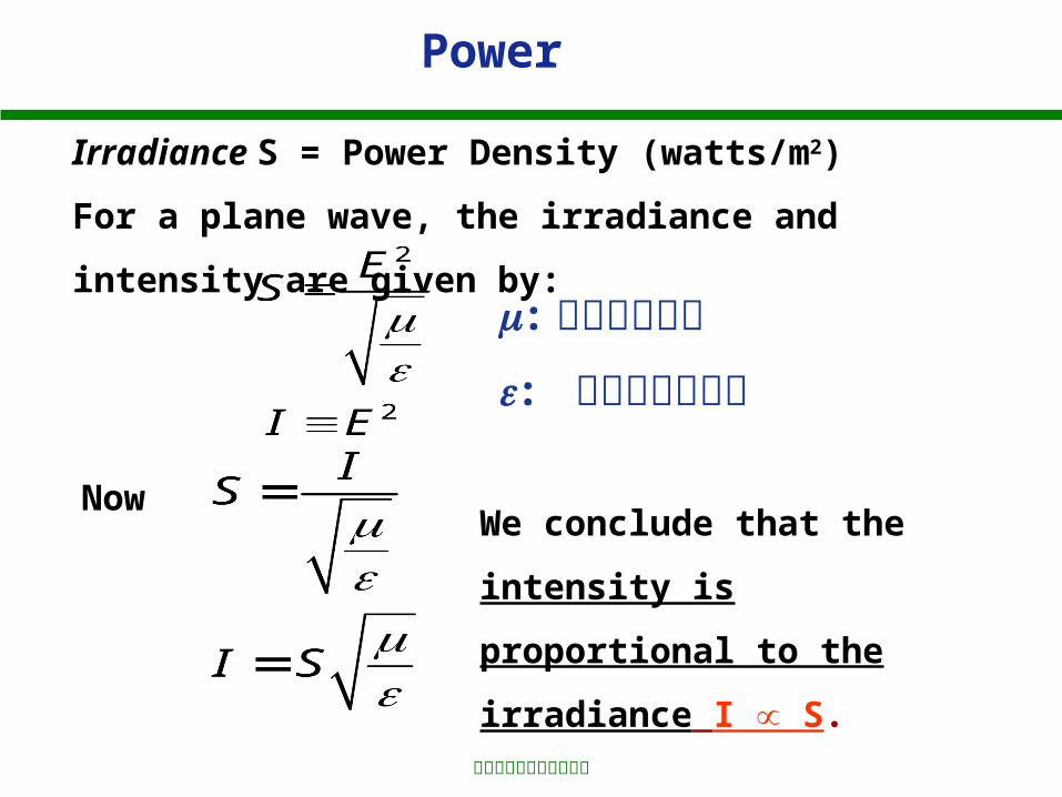
Irradiance S = Power Density (watts/m2)
For a plane wave, the irradiance and intensity are given
by:
NowWe conclude that the
intensity is proportional to
the irradiance I S∝ .
Power
: 材料的磁导率
: 材料的介电常数

上海师范大学电气信息系
Electromagnetic Waves
Recall the plane wave given by
This expression represents a wave traveling with zero
loss.
(3.1)
If loss occurs, the field is represented by
sin( )zoE E t kze (3.8)
is the attenuation coefficient for E.
The frequency and phase do not vary with loss, only
the amplitude of the wave Eoe-z changes with loss.

上海师范大学电气信息系
P∝E2, for a path length L in a lossy medium, the power
diminishes by a factor of:2 Le
The corresponding P (or I) reduction in dB is:210lg LdB e
This will be a negative number for propagation through a
lossy medium.
Define: (dB/km) in terms of the attenuation coefficient
. = -8.685 proofIf L is in unit of km, then is in units of km-1.
2 is the attenuation coefficient for P
Electromagnetic Waves

上海师范大学电气信息系
Wave Traveling in a Lossy Medium
t2
t1
Distance (z)
Ele
ctri
c F
ield
Electromagnetic Waves

上海师范大学电气信息系
3.2 Dispersion, Pulse Distortion, Information Rate
When we write E = Eosin (t – kz), we imply a single
frequency source.
Frequency
Radio oscillators approximate single f pretty well.
Optical sources do not produce single f.

上海师范大学电气信息系
Example : Emission Spectrum of an Optical Source
f = source bandwidth (range of frequencies emitted by
the source).
f is the central frequency.
1
0.5
f
Frequency
Normalized Power
ff1 f2
Dispersion, Pulse Distortion, Information Rate

上海师范大学电气信息系
Alternatively, we can plot the wavelength emission
spectrum as follows:
= linewidth or spectral width
1
0.5
Wavelength
Normalized Power
21
Dispersion, Pulse Distortion, Information Rate

上海师范大学电气信息系
Example: If = 0.82 m, = 30 nm
so we have 3.7% bandwidth.
The conversion between wavelength and frequency is:
(3.9)
f
f
Dispersion, Pulse Distortion, Information Rate

上海师范大学电气信息系
Proof:
The mean frequency is: f = c/
Define the mean wavelength as:
Then,
Now, we have
212
Dispersion, Pulse Distortion, Information Rate

上海师范大学电气信息系
Spectral Widths for Typical Light Sources (table 3.1)
Source Spectral Width (nm)
LED 20-100
Laser Diode 1-5
Nd:YAG-Laser(固态钇铝石榴石 ) 0.1
He-Ne Laser 0.002
Dispersion, Pulse Distortion, Information Rate

上海师范大学电气信息系
If = 0, (f = 0), the source is perfectly coherent.
It is monochromatic (单色) .
Laser diodes are more coherent than LEDs, but are
not perfectly coherent.
We will see how source bandwidth limits the
information capacity of fiber transmission lines.
Dispersion, Pulse Distortion, Information Rate

上海师范大学电气信息系
3.2.1 Material Dispersion and Pulse Distortion
Recall that v = c/n.
For glass, n varies with wavelength. Thus, waves
of different wavelengths (frequencies) travel at
different speeds.
Dispersion:
Wavelength dependent propagation velocity.
Material Dispersion: Dispersion caused by the material.
Waveguide Dispersion: Dispersion caused by the
structure of the waveguide.

上海师范大学电气信息系
Consider a pulse of light emitted by a source which contains a range of wavelengths (say 1, 2, 3).
Input Power
t
t
t
1
tT
2
3
Fastestwavelength
Slowest wavelength
Output Power
t
t
t
t
1
2
3
T +
Arrives last
Arrives first
Material Dispersion and Pulse Distortion

上海师范大学电气信息系
Because of dispersion, the components of the input
pulse at 1, 2, and 3 travel at different speeds and
thus arrive at the receiver at different times. The
previous slide displayed how this phenomenon spreads
pulses as they travel along a dispersive medium. The
output is widened by an amount we label as .

上海师范大学电气信息系
Dispersion also distorts an analog signal waveform.
Input Power Output Power
Pac,in Pac,out
1
2
Slower wavelength
1
2
Pac,out < Pac,in
Information is contained in the amplitude variation.
t t

上海师范大学电气信息系
DISPERSION
Refractive Index Variation for SiO2
First Derivative
o
n’
dn/d0
1.45
o
Inflection Point
0
n
Second Derivative
o
dn2/d2
0
n’’
Inflection point for SiO2 glass occurs near wavelength: 1300 nm

上海师范大学电气信息系
Find the amount of pulse spread due to material dispersion.
Let = time of travel of a pulse over path length L.
With No Dispersion
With Dispersion Present
/L
1 2
L
(/L)2
(/L)1
/L
The source linewidth is taken to be (with 2 > 1):
= 2 - 1

上海师范大学电气信息系
where 1 is the fastest and 2 is the slowest wavelength.
(3.10)
The pulse spread per unit length is then:
(/L)/ = d(/L)/d ( slope of the curve )Pulse spread per unit length: (/L) = [d(/L)/d
(3.12)
Actual spread would be:
1 2
L
(/L)2
(/L)1
/L

上海师范大学电气信息系
(/L) = [d(/L)/d L’ (3.12)
Two distinct terms determine the pulse spread
1. the slope of the /L curve
2. the linewidth of the source.
The linewidth will be available from manufacturer's
data or must be measured.
Further analysis shows that:
The prime and double prime denote first and second
derivatives.
(3.13)

上海师范大学电气信息系
Proof:
Pulses travel at a speed called the group velocity u.
The group velocity is given by:
The pulse travel time is thus:
This is the pulse travel time per unit of path length.

上海师范大学电气信息系
( is the free space value)If n (), then (/L)’ = 0 and there is no dispersion and no pulse
spread.

上海师范大学电气信息系
Define material dispersion M :
(3.14)
Combining (3.12) and (3.13):
M (ps/nm/km) is in picoseconds of pulse spread per nanometer of source spectral width and per kilometer of fiber length.
1.3 1.55
0.82
110
-20
M(ps/(nm.km))
(m)
SiO2

上海师范大学电气信息系
1. For M > 0 (wavelengths < 1.3 m)
Wavelength 2 arrives before wavelength 1.
Energy at 2 travels faster than energy at 1. (2 > 1)
2. For M < 0 (wavelengths > 1.3 m)
So that 1 travels faster than wavelength 2.
3. At 1.3 m, M = 0 , and there is no material dispersive pulse spreading.

上海师范大学电气信息系
Example: Consider an LED at = 0.82 m, L = 10 km, and = 20 nm. Find (/L).
From the graph, at 0.82 m, M =110 ps/(nm·km).
Change the wavelength to = 1.5 m, = 50 nm. At 1.5 m, M = -15 ps/nm·km. Then

上海师范大学电气信息系
Example: = 0.82 m, = 1 nm. M = 110 ps/(nm·km)
ns
nspsnmkmnm
pskm
LL
1.1
1.11100111010
Example: = 1.5 m, = 1 nm. M = -15 ps/nm·km

上海师范大学电气信息系
Between 1200 nm and 1600 nm(near the inflection point), M is given by
Mo = -0.095 ps/(nm2•km) and o is the zero dispersion
wavelength ( 1300 nm).
Conclusion:
•The longer the path the greater the pulse spread.
•The greater the source spectral width, the greater
the pulse spread.

上海师范大学电气信息系
A soliton is a pulse that travel without spreading. The refractive index of glass depends upon the pulse intensity. This fiber nonlinearity is used to counter the effects of dispersion. The leading edge of the pulse can be slowed down, and the trailing edge speeded up to reduce spreading. Thus, the pulse must be properly shaped.
3.2.2 Solitons
The nonlinearity is such that solitons are only produced at wavelengths longer than the zero-dispersion wavelength in glass fibers. Compensation to overcome pulse broadening is only possible in the longer wavelength region range 1300 to 1600 nm.

上海师范大学电气信息系
单脉冲传输 800km 时孤子脉冲波形的演变
-10
0
100
200
400
600
8000
1
2
3
4
5
x 10-3

上海师范大学电气信息系
基态和高阶孤子沿光纤传输时的变化特点

上海师范大学电气信息系
Solitons overcome the bandwidth limitations of the
fiber, but not the attenuation. Optical amplifiers are
needed along the transmission path to maintain the
pulse energy above the minimum required for
soliton production.
Fiber
Amplifier
上海师范大学电气信息系
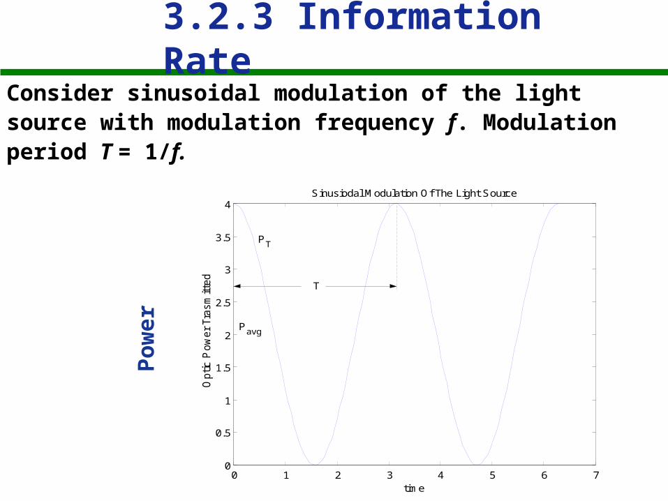
3.2.3 Information RateConsider sinusoidal modulation of the light source with modulation frequency f. Modulation period T = 1/f.
0 1 2 3 4 5 6 70
0.5
1
1.5
2
2.5
3
3.5
4
time
Optic P
ow
er
Tra
sm
itte
dSinusiodal Modulation Of The Light Source
PT
Pavg
T
Po
wer

上海师范大学电气信息系
Information Rate
consder
0 1 2 3 4 5 6 70
0.2
0.4
0.6
0.8
1
1.2
1.4
1.6
1.8
2Maximum Allowable Pulse Spead At The Receiver
time
Opt
ic P
ower
Rec
eive
r
PR
T
T/2
This spread reduces the total power variation to zero.
Modulation is canceled.
Blue: 1
Red: 2
TimeT/2
Information Rate

上海师范大学电气信息系
The limit on the allowable pulse spread will be
taken to be:
2
T (2)
Information Rate

上海师范大学电气信息系
so that the modulation frequency has the limits: 1
2f
The maximum modulation frequency is then:
(4)
From (2) we have the requirement that 1/T < 1/(2)(3)
This modulation frequency turns out to be the 3-dB
bandwidth. The signal is actually reduced by half (3-dB)
at this modulation frequency.
2
13 dBf (5)3-dB optical bandwidth:
Information Rate
max
1
2f

上海师范大学电气信息系
The total signal loss has two parts and can be expressed
by the equation:
(6)
La = Loss due to absorption and scattering (fixed loss).
Lf = Modulation (message) frequency dependent loss.
The modulation frequency dependent loss is given by:
(7)
Information Rate

上海师范大学电气信息系
Example: Suppose f = f3-dB. Compute the loss.
Example: Suppose f << f3-dB. Compute the loss.
The equation predicts no modulation frequency loss for modulation frequencies well below the 3-dB frequency.
Information Rate

上海师范大学电气信息系
Example: Suppose f = 0.1 f3-dB. Compute the loss.
Maximum frequency length product is calculated from (5) as follows:
3 2dB
Lf L
(8)
(3.16)
3
1 0.5
2dBf (5)
3
1
2dBf L
L
Information Rate

上海师范大学电气信息系
Find the frequency at which Lf = 1.5 dB.
Use (7) for Lf
2
3
ln 2
1.5 10lg dB
f
fe
2
3
ln 2
10lg dB
f
ffL e
(7)
1.5 30.71dB dBf f
Solving for the frequency at which the loss is 1.5
dB, we obtain
Information Rate

上海师范大学电气信息系
Now consider the photodetection circuit:
RL
P
Photodetector
Optical Power
i
P = incident optic power
i = P detector output current
= detector responsivity (A/w)
The electrical power in the load resistor RL is:
222
2
)( PRPRP
iRP
LLe
Le
Information Rate

上海师范大学电气信息系
Consider two optical power levels P1 and P2 and their corresponding electrical power levels Pe1 and Pe2.
2electrical opticaldB dB
Information Rate

上海师范大学电气信息系
Examples:
•A loss of 3 dB in optical power yields a loss of 6
dB in the corresponding electrical power.
•A loss of 1.5 dB in optical power yields a loss of 3
dB in the corresponding electrical power.
Information Rate

上海师范大学电气信息系
We found that the modulation frequency at which
the optical loss is 1.5 dB was:
3 ( )
0.35dB electricalf L
L
Electrical 3-dB bandwidth length product is:
(3.19)
(3.18)
Information Rate
上海师范大学电气信息系
t
tp
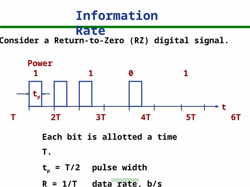
Consider a Return-to-Zero (RZ) digital signal.
Power 1 1 1 0 1
0 T 2T 3T 4T 5T 6T 7T
Each bit is allotted a time T.
tp = T/2 pulse width
R = 1/T data rate, b/s
Information Rate

上海师范大学电气信息系
Spectrum of the RZ Signal
Most of the signal power lies below 1/T Hz, so the required transmission bandwidth by a system is:
RT
BRZ 1
FrequencyptTT
121
PowerSpectralDensity(Watts/Hz)
0
Information Rate

上海师范大学电气信息系
If the system passes this band of frequencies the
pulses will be recognizable. To be conservative,
use the 3-dB electrical bandwidth.
(3.20)0.35
RZR L
L
The RZ rate length product is then:
Information Rate

上海师范大学电气信息系
We obtain the same result by allowing a pulse
spread of 70% of the initial pulse duration.
As on the preceding slide.
Information Rate
上海师范大学电气信息系
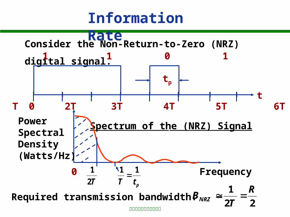
Consider the Non-Return-to-Zero (NRZ) digital signal.
t
tp
1 1 1 0 1
T 2T 3T 4T 5T 6T 7T0
Spectrum of the (NRZ) Signal
Required transmission bandwidth:22
1 R
TBNRZ
FrequencyptTT
11
2
1
PowerSpectralDensity(Watts/Hz)
0
Information Rate

上海师范大学电气信息系
The allowed data rate is:
Use the electrical 3-dB bandwidth:
0.7NRZR L
L
NRZ rate length product is:
(3.21)
Comparing the results for the RZ and NRZ data rates:
Information Rate

上海师范大学电气信息系
BANDWIDTH DATA RATE SUMMARY
Information Rate

上海师范大学电气信息系
3.3 Polarization
Linearly polarized: An electric field points in just one direction, it always
points along a single line.a. Linearly polarized in x direction and traveling in the
z direction.b. linearly polarized in y direction and traveling in the
z direction.
yz
xE
v
yz
xE
v
(a) (b)

上海师范大学电气信息系
1. The two orthogonal linear polarizations are the
plane wave modes of an unbounded media.
2. They can exist simultaneously.
3. The actual polarization is determined by the
polarization of the light source and by other
polarization sensitive components in the optical
system.
Polarization
上海师范大学电气信息系
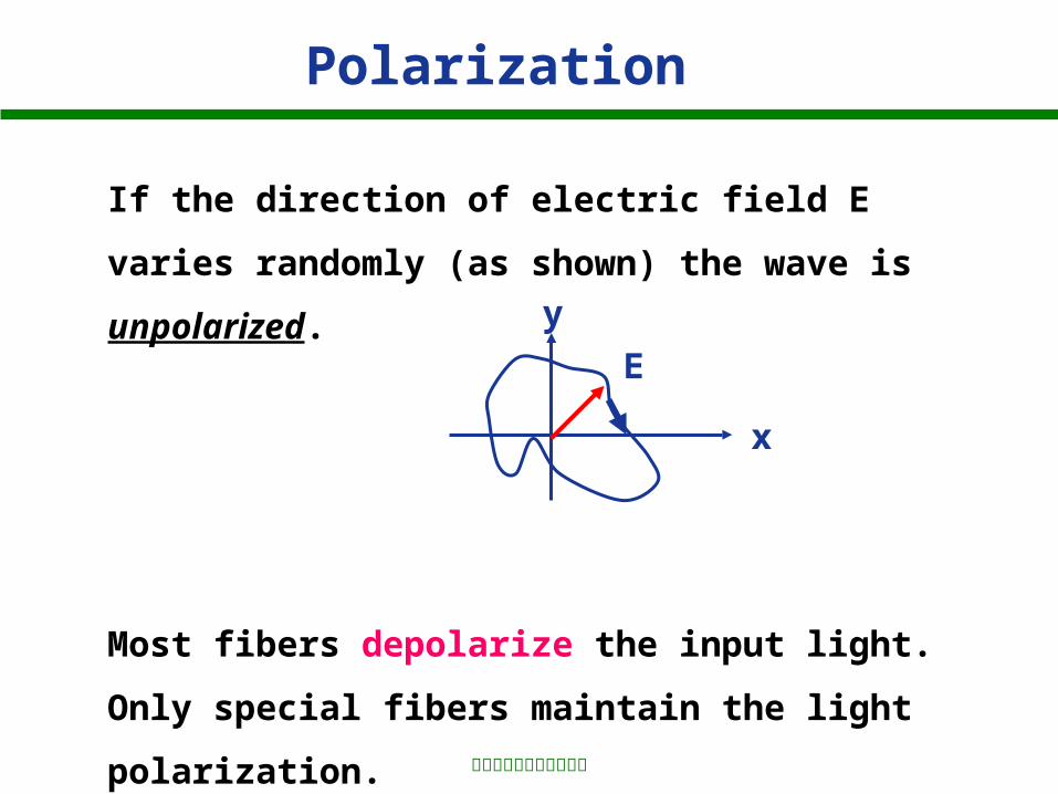
If the direction of electric field E varies randomly (as
shown) the wave is unpolarized.
Most fibers depolarize the input light. Only special
fibers maintain the light polarization.
x
y
E
Polarization

上海师范大学电气信息系
L
镜子
镜子
A
1 、让任意一个光波从左边的镜子传向右边的镜子,如 A 图所示。绿波在右边的镜子处发生发射,因此这个波经历了一次 180 度相移。从 A 图我们可以看出,这个波在其相位上发生了中断,在这里应该是不可能的,也就是说,这个谐振器不支持这个波。
L
镜子
镜子
B
2 、在图 B 中,在右边的镜子处,这个波也发生了一个 180 度相移,然后继续传播,在左边的镜子处,同样经历了一个 180 度相移,然后继续传播。因此,图 B 所示的波有着一个稳定的模式,我们称之为驻波
3.4 Resonant Cavities

上海师范大学电气信息系
2
2
L m
mL
Design:The cavity must be an integral number of half wavelengths long to support a wave.
The wavelength is that in the medium filling the cavity.
(3.22)L
Standing-wave pattern in a cavity (m = 4)
Resonant Cavities

上海师范大学电气信息系
m
L2
The resonant wavelengths are:
Ln
cm
L
m
n
cf
n
cf
vf
22
The corresponding resonant frequencies are:
(3.23)
Resonant Cavities

上海师范大学电气信息系
Cavity Resonant frequencies
2c
cf
nL
211 mmmm ffff
This picture shows the longitudinal modes of the cavity.
Frequency
The resonant frequency spacing is:
1
( 1)
2 2 2
c m m
c
f f f
m c mc cf
Ln Ln Ln
(3.25)
Resonant Cavities

上海师范大学电气信息系
2
c c
o
o c o cc
o
f
f
f fc c
The free space wavelength spacing corresponding
to fc is c calculated from:
(3.26)
This equation refers to the free space wavelengths.
Resonant Cavities

上海师范大学电气信息系
Example: Consider an AlGaAs laser cavity.
L = 0.3 mm = 300 m; n = 3.6; o = 0.82 m.
Find the cavity resonant wavelength spacing c.
Resonant Cavities

上海师范大学电气信息系
Example: Suppose the AlGaAs, LD has a spectral width of 2 nm. Determine the number of longitudinal modes in the output.
0.82 m
2 nm
0.82 m
Gain (AlGaAs)
Cavity Resonances
c
Resonant Cavities

上海师范大学电气信息系
2 nm
0.82 m
c
Laser Output
The laser emits 6 longitudinal modes.
A laser emitting only one longitudinal mode is a
single-mode laser.
Resonant Cavities

上海师范大学电气信息系
3.5 Reflection at a Plane Boundary
Consider normal incidence of light at a boundary.
This is referred to as Fresnel Reflection.n1 n2
Incident Wave Transmitted Wave
Reflected Wave
Reflection Coefficient:
reflected electric field
incident electric field
Boundary
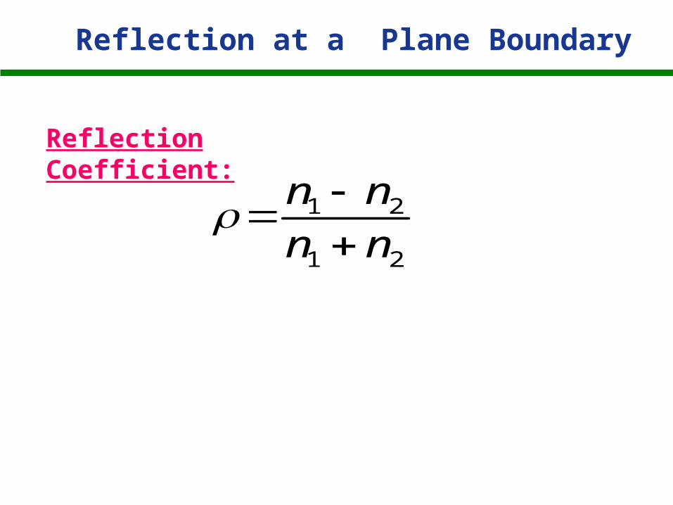
1 2
1 2
n n
n n
Reflection Coefficient:
Reflection at a Plane Boundary
上海师范大学电气信息系
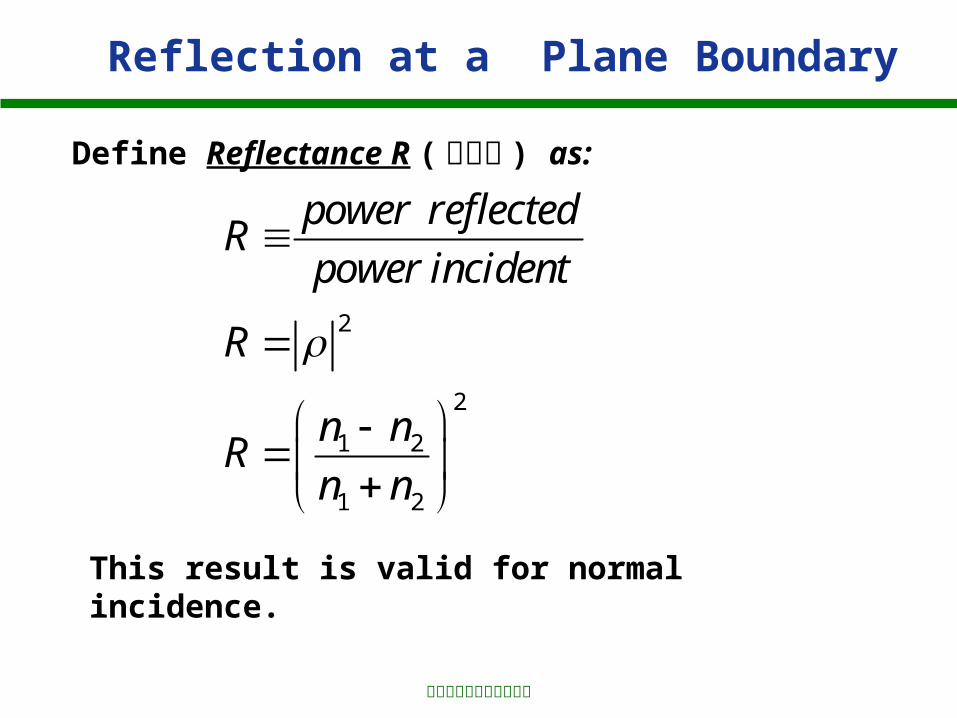
2
2
1 2
1 2
power reflectedR
power incident
R
n nR
n n
Define Reflectance R ( 反射比 ) as:
This result is valid for normal incidence.
Reflection at a Plane Boundary

上海师范大学电气信息系
For air-to-glass, compute the transmitted power.
4% power reflected. 96% power transmitted.
In dB, the transmitted power is:
10 lg (0.96) = -0.177 dB
Typically we round this off to 0.2 dB (omitting the
minus sign). This is called the Fresnel loss.
Reflection at a Plane Boundary

上海师范大学电气信息系
Consider arbitrary incidence:
Perpendicular Polarization (s) 垂直偏振
n1 n2
r
t
i
Ei
Er
Et
Reflection at a Plane Boundary

上海师范大学电气信息系
Consider arbitrary incidence:
Parallel Polarization (p)平行偏振
n1 n2
r
t
i
Ei
Er
Et
Reflection at a Plane Boundary

上海师范大学电气信息系
Plane of Incidence( 入射平面 )
Defined by the normal to the boundary and the ray
direction of the incident beam.
z
x
The xz plane is the plane of incidence in this example.
Incident Boundary
Reflection at a Plane Boundary

上海师范大学电气信息系
Fresnel’s Law of Reflection
2 2 2 22 1 2 1
2 2 2 22 1 2 1
cos sin
cos sin
i ip
i i
n n n n
n n n n
For parallel polarization, the reflection coefficient:
Note that may be complex.
(3.29)
(3.30)
For perpendicular polarization, the reflection coefficient:
Reflection at a Plane Boundary
2 2 21 2 1
2 2 21 2 1
cos sin
cos sin
i is
i i
n n n
n n n

上海师范大学电气信息系
Plots of p and s for n1 = 1 (air), n2 = 1.48 (glass)
Parallel (p)
Perpendicular (s)
s
p
Angle of incidence (i)
Reflection at a Plane Boundary

上海师范大学电气信息系
From equation (3.29) for parallel polarization, we can get total transmission (no reflection) if
2 2 2 22 1 2 1cos sini in n n n
The angle satisfying this equation is the Brewster
angle B. The solution is:2
1
tan B
n
n
Compute B for air-to-glass and glass-to-air:
For n1 = 1, n2 = 1.5
For n1 = 1.5, n2 = 1
For perpendicular polarization there is no Brewster angle. No i s.t. Equ.3.30 = 0.
Reflection at a Plane Boundary

上海师范大学电气信息系
Antireflection CoatingsWe have just seen that we can transmit a beam from one material to another without reflection under Brewster angle conditions. We can also transmit with no (or very little) reflection by placing a coating between the two materials.
The thickness of the coating is a quarter wavelength. The reflectance R for this configuration is:
n1 n2 n3
/4
221 3 2
221 3 2
n n nR
n n n
Reflection at a Plane Boundary

上海师范大学电气信息系
Clearly, the reflectance becomes zero if: 2 1 3n n n
A coating that reduces the reflectance is called an
antireflection (AR) coating . 消反射涂覆
Example: Compute the reflectance when a quarter
wavelength of magnesium fluoride ( 氟化镁 n = 1.38) is
coated onto a piece of glass (n = 1.5).
Solution:
The reflectance is:
22
22
1.5 1.380.014
1.5 1.38R
4% → 1.4%
Reflection at a Plane Boundary

上海师范大学电气信息系
3.6 Critical Angle Reflection
Fresnel’s Law of Reflection
2 2 2 22 1 2 1
2 2 2 22 1 2 1
cos sin
cos sin
i ip
i i
n n n n
n n n n
For parallel polarization:
(3.29)
(3.30)
For perpendicular polarization:
2 2 21 2 1
2 2 21 2 1
cos sin
cos sin
i is
i i
n n n
n n n

上海师范大学电气信息系
From equations (3.29) and (3.30), we find that
1
2sinn
nc
Call the solution c, the critical angle.
c exists only if n1 > n2. That is, travel from a high index to a low index material. This result is valid for both polarizations.
(3.34)
The incident angle satisfying this equation is the angle whose sine is given by:
Critical Angle Reflection

上海师范大学电气信息系
is purely imaginary.
If then
Under this condition, equations (3.29) and (3.30) can
be written in the form:
where A, B, C, and D are real and j is the imaginary
term
Critical Angle Reflection

上海师范大学电气信息系
Then:
We conclude that there is complete reflection (called
critical angle reflection) for all rays which satisfy the
condition: ci
Critical Angle Reflection

上海师范大学电气信息系
Consider waves undergoing critical angle reflections:
n1 n2
In region n1 we have a standing wave due to the
interference of the incident and reflected waves.
i c i
Critical Angle Reflection
上海师范大学电气信息系
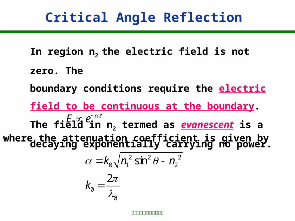
In region n2 the electric field is not zero. The
boundary conditions require the electric field to be
continuous at the boundary. The field in n2 termed as
evanescent is a decaying exponentially carrying no
power.
2 2 20 1 2
00
sin
2
k n n
k
where the attenuation coefficient is given by
Critical Angle Reflection
zE e

上海师范大学电气信息系
Consider a wave where
The decaying wave carries no power in the z-direction.
Evanescent Wave
E
z
Standing Wave
n1 n2Envelope
e-z
i c
At the critical angle,
In this case, there is no decay. The wave penetrates deeply into the second medium.
Critical Angle Reflection
这里衰减因子和前面提到的衰减系数不同,衰减系数是指功率的实际损耗,这里衰减因子并不具有这样的含义,仅仅指电磁波回到入射区之前,场在第二种介质中要传播多远。

上海师范大学电气信息系
As i increases, increases and the decay becomes
greater. = 0, = c |E|
z
i > c
As i increases from c towards 90o, increases
and the evanescent field penetrates less and less
into the second medium.
0
i
e-z
Critical Angle Reflection

上海师范大学电气信息系
LIGHTWAVE FUNDAMENTALS
•Pulse spread
•3-dB bandwidths
•Rate-length products
•Reflectance
•Critical angle reflections