Серводвигатели серии blq magnetic
TRANSCRIPT

servomotori brushless a magneti permanenti serie BLQpermanent magnet brushless servomotors BLQ series

generalità | general featuresI servomotori brushless a magneti permanenti derivano dalle esigenze semprepiù spinte dell’automazione industriale che necessita di sistemi a sempre piùelevate prestazioni e affidabilità con ridotta manutenzione.La MAGNETIC interpretando le esigenze di mercato e affinando con l’esperien-za di numerose applicazioni diverse ha consolidato due distinte serie di moto-ri: una per applicazioni generiche che necessitano di una buona rotondità dimoto, inerzia non troppo ridotta per agevolarne il controllo e una grande varie-tà di personalizzazioni, l’altra per applicazioni ad altissima dinamica e dove gliingombri richiesti sono particolarmente ridotti.Ambedue le serie utilizzano magneti dell’ultima generazione in neodimio-ferro-boro e soluzioni tecniche che assicurano:> F.C.E.M. sinusoidale> intercambiabilità con le ns. serie precedenti e con le esecuzioni più diffuse
presenti sul mercato> ridotto momento d’inerzia con conseguenti elevate accelerazioni e decelerazioni> elevata capacità di sovraccarico> bassa pendolazione di coppia> avvolgimento trifase a stella senza neutro accessibile> esecuzione non ventilata IC400 (CEI EN 60034-6) con grado di protezio-
ne IP 54 (CEI EN 60034-5)> dimensionamento in classe F (CEI EN 60034-1 - ΔTmax=105K) pur utiliz-
zando isolanti in classe H> forma costruttiva B5 (CEI EN 60034-7), trasformabile in V1 o V3 senza
modifiche> protezione termica realizzata con termoprotettore a contatto normalmen-
te chiuso avente le seguenti caratteristiche:- Temperatura di intervento 135 ± 5°C- Tensione massima 48 Vcc, 230 Vca- Max portata dei contatti 6 Acc, 6 Aca (cosΦ =0.6)
1,3 Acc, 1,6 Aca (cosΦ =0.6)su BLQ 23-33 e la serie TOP
L’esecuzione meccanica particolarmente robusta assicura un’ottima affidabili-tà delle parti. I materiali isolanti utilizzati e i controlli eseguiti sia durante lefasi di costruzione degli avvolgimenti e al collaudo finale assicurano un’ottimaaffidabilità nelle condizioni di alimentazione tipiche: invertitore a PWM coningresso diretto da rete.
The brushless servomotors with permanent magnets are designed to meetthe more and more demanding needs of industrial automation with very high-performances and reliable systems requiring little maintenance.MAGNETIC, to meet the market requirements and on the ground of its expe-rience of many different applications, has defined two different motor series:one for generic applications that need a good rotation regularity, an inertianot too low to make the control easier and a wide range of customized exe-cutions; the other series for high dynamic special applications with overalldimensions particularly reduced. These two series of servomotors use thelast generation magnets made of neodymium, iron and boron and advancedtechnical solutions to obtain:> sinusoidal B.E.M.F.> interchangeability with our previous series and with the most common
servomotors present on the market> low moment of inertia resulting in high accelerations and decelerations> high overload capacity> low cogging of torque.> three-phase, 4 pole star winding with no access to neutral> TENV execution IC400 (IEC 34-6) with degree of protection IP 54
(IEC60034-5)> dimensioning in F class (IEC34-1; ΔT=105K), even if the insulation used
is of H class> assembly B5 (IEC34-7), with the possibility of transforming it into V1 or
V3 without changes> normally-closed contact foreseen for thermal protection with the follo-
wing characteristics:- Operating temperature 135±5°C- Ceiling voltage 48 Vdc, 230 Vac- Capacity of the contacts 6 Adc, 6 Aac (cosϕ =0.6)
1,3 Adc, 1,6 Aac (cosϕ=0.6)for BLQ 23-33 and TOP series
The mechanical execution particularly rugged assures a very high reliabilityof the components. The insulation materials used and the tests made duringthe windings manufacturing phase and the final testing assure the operatingin the typical supplying conditions: PWM inverter with input from transfor-mer or direct to the mains.
2 | BLQ

Questa serie si sviluppa su 3 taglie 25-35-100. Particolarmente apprezzatesono le caratteristiche di bassa ondulazione di coppia e adeguato valore d’iner-zia che porta ad un miglior controllo dell’asse anche in applicazioni come lamacchina utensile.Sono definiti per una tensione di alimentazione max (Vca) pari a 3x205 VRMS
(tensione di rete 3x230V)i tipi BLQ 23, 33 e 103 mentre per tensione Vcapari a 3x345 VRMS (tensione di rete 3x400V) i 104.Le dimensioni meccaniche delle due serie sono le stesse. Per applicazioni cherichiedono elevate coppie continuative anche ad alte velocità (regolazione acoppia costante), è disponibile l’esecuzione ventilata del BLQ 103 e 104.
The BLQ series includes 3 frames (25-35-100).Low torque ripple and adequate inertia value are characteristics particularlyappreciated that allow a better control even in applications as the tool machines.The max supply voltage (Vac) for the 23, 33 and 103 types is 3x205 VRMS
(mains 3x230V), while the 104 are designed for Vac=3x345 VRMS (mains3x400V). The mechanical dimensions of these two series are the same.For applications that require high continuous torques even at high speed(costant torque regulation) the execution with fan is availablefor BLQ 103 and 104.
BLQ | 3
* Versione speciale, rivolgersi all’ufficio commerciale MAGNETIC* Special version, please contact MAGNETIC sales dpt.
definizione dei parametri |parametersI valori riportati nelle tabelle corrispondono alle seguenti definizioni:> Coppia di stallo Tn1: coppia continuativa erogabile dal motore a velocità
prossima a zero con ΔTmax=105K (Tamb.max=40°C)> Coppia di stallo Tn2: coppia continuativa erogabile dal motore a velocità
prossima a zero con ΔTmax=65K (Tamb.max=40°C)> Coppia massima Tp: coppia massima di accelerazione erogabile dal motore> Velocità massima nmax: velocità massima con carico pari alla coppia di stal-
lo Tn1 e tensione al motore pari alla massima erogabile dal convertitore(Vca)
The values indicated on the tables correspond to what follows:> Stall torque Tn1: continuous torque that may be supplied by the motor
while running at a speed near zero with ΔTmax=105K (max room T=40°C)> Stall torque Tn2: continuous torque that may be supplied by the motor
while running at a speed near zero with ΔTmax=65K (max room T=40°C)> Max torque Tp: acceleration torque that may be supplied by the motor> Max speed nmax: max speed when the load is equal to the stall torque Tn1
and the voltage supplied to the motor is equal to the max voltage that maybe delivered by the converter (Vac)
> Area 1: poiché l’aumentare della velocità determina mag-giori perdite nel motore, occorre considerare un declas-samento della coppia continuativa (S1 CEI EN 60034-1)in funzione della velocità.
> Area 2: nella scelta del motore necessita considerare lavelocità fino a cui viene richiesta l’erogazione della coppiamassima richiesta: la limitazione è dovuta alla tensionemassima fornibile dal convertitore. A tal senso le tabelle dipagina 4 forniscono valori di velocità massima (nmax2 enmax3) corrispondenti a 2 volte la coppia di stallo Tn1 e allacoppia massima Tp. Affinchè il motore possa fornire coppiadi sovraccarico alla velocità richiesta, risulta necessariosceglierlo con velocità massima maggiore.
> Area 1: since an increase in speed results in bigger los-ses of the motor, it is necessary to derate the continuoustorque (S1 IEC34-1) according to the speed.
> Area 2: when choosing the motor it is necessary to takeinto account the speed up to which the max torque has tobe supplied; this depends on the max voltage which maybe delivered by the converter. To this purpose, tables onpage 4 provides maximum speed values (nmax2 and nmax3)corresponding to the stall torque Tn1 multiplied per 2 andto the max torque Tp are given in the tables on pages 3,4, 5. It is necessary to choose the motor with a highermax speed in order to obtain the overload torque at thedesired speed.
TP
2xTn1
Tn1
Nmax3 Nmax2 Nmax
2
1
motore tipo / motor type BLQ 23 BLQ 33 BLQ 103 - BLQ 104
CARATTERISTICHE DEI CUSCINETTI / BEARINGS DATA
cuscinetto lato accoppiamento / shaft end bearing 6200 2RS1 6202 2RS1 6209 2RS1
cuscinetto lato opposto / opposite end bearing 61900 2Z 16002 2Z 6307 2Z
CARATTERISTICHE DELL’OPZIONE FRENO / OPTION BRAKE FEATURES
tipo / type 04* 06H 14
coppia frenante / braking torque Nm 1.2 3.2 40
corrente assorbita / nominal current Adc 0.33 0.50 1.46
momento d’inerzia agg. / additional inertia x10-4 kgm2 0.14 0.5 36
tempo di risposta in ins. / insertion response time x10-3 s 4 29 100
tempo di risposta in disins. / fall response time x10-3 s 3 19 30
peso aggiuntivo / additional weight kg 0.3 0.3 3.5
caratteristiche principali |main characteristics
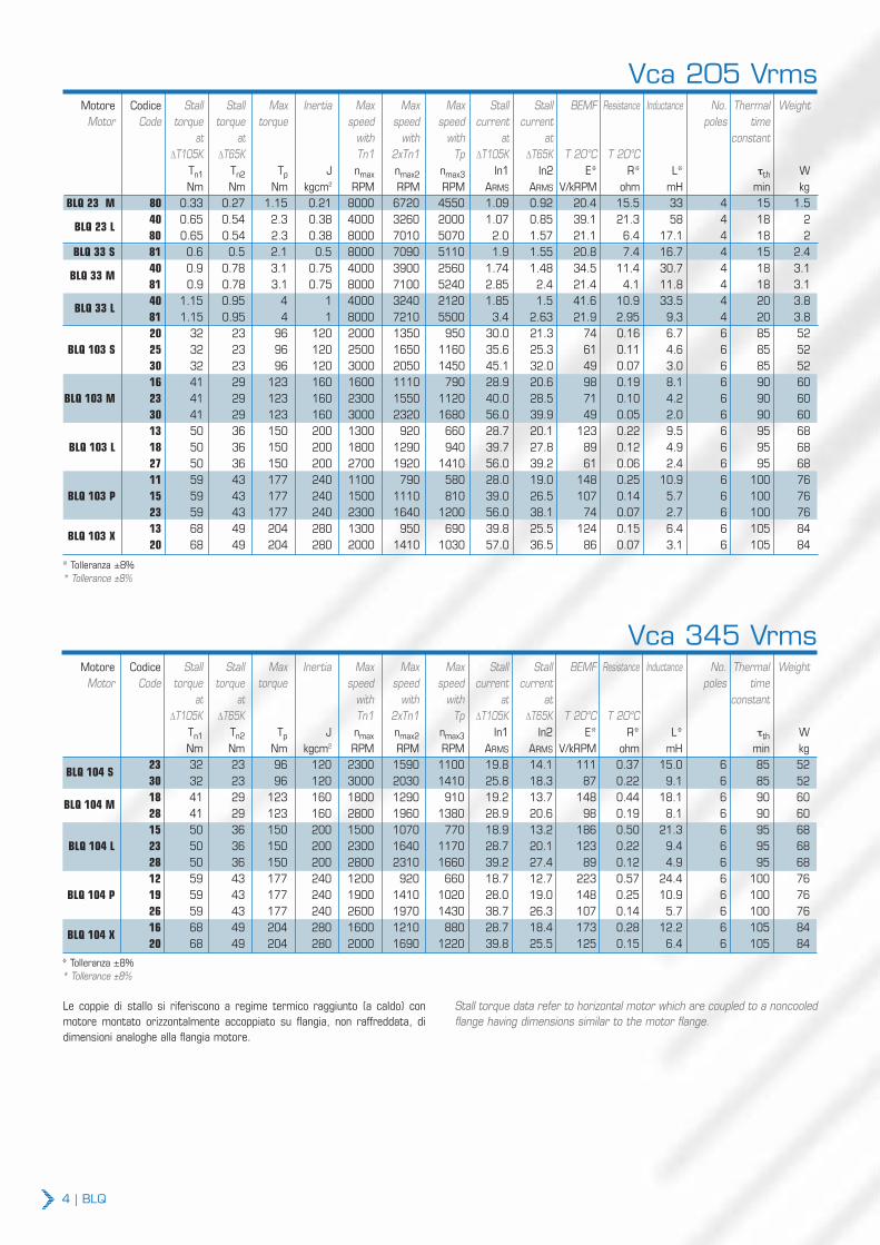
Le coppie di stallo si riferiscono a regime termico raggiunto (a caldo) conmotore montato orizzontalmente accoppiato su flangia, non raffreddata, didimensioni analoghe alla flangia motore.
Stall torque data refer to horizontal motor which are coupled to a noncooledflange having dimensions similar to the motor flange.
4 | BLQ
Motore Codice Stall Stall Max Inertia Max Max Max Stall Stall BEMF Resistance Inductance No. Thermal WeightMotor Code torque torque torque speed speed speed current current poles time
at at with with with at at constantΔT105K ΔT65K Tn1 2xTn1 Tp ΔT105K ΔT65K T 20°C T 20°C
Tn1 Tn2 Tp J nmax nmax2 nmax3 In1 In2 E* R* L* τth WNm Nm Nm kgcm2 RPM RPM RPM ARMS ARMS V/kRPM ohm mH min kg
BLQ 104 S23 32 23 96 120 2300 1590 1100 19.8 14.1 111 0.37 15.0 6 85 5230 32 23 96 120 3000 2030 1410 25.8 18.3 87 0.22 9.1 6 85 52
BLQ 104 M18 41 29 123 160 1800 1290 910 19.2 13.7 148 0.44 18.1 6 90 6028 41 29 123 160 2800 1960 1380 28.9 20.6 98 0.19 8.1 6 90 6015 50 36 150 200 1500 1070 770 18.9 13.2 186 0.50 21.3 6 95 68
BLQ 104 L 23 50 36 150 200 2300 1640 1170 28.7 20.1 123 0.22 9.4 6 95 6828 50 36 150 200 2800 2310 1660 39.2 27.4 89 0.12 4.9 6 95 6812 59 43 177 240 1200 920 660 18.7 12.7 223 0.57 24.4 6 100 76
BLQ 104 P 19 59 43 177 240 1900 1410 1020 28.0 19.0 148 0.25 10.9 6 100 7626 59 43 177 240 2600 1970 1430 38.7 26.3 107 0.14 5.7 6 100 76
BLQ 104 X16 68 49 204 280 1600 1210 880 28.7 18.4 173 0.28 12.2 6 105 8420 68 49 204 280 2000 1690 1220 39.8 25.5 125 0.15 6.4 6 105 84
Vca 345 Vrms
* Tolleranza ±8%* Tollerance ±8%
Motore Codice Stall Stall Max Inertia Max Max Max Stall Stall BEMF Resistance Inductance No. Thermal WeightMotor Code torque torque torque speed speed speed current current poles time
at at with with with at at constantΔT105K ΔT65K Tn1 2xTn1 Tp ΔT105K ΔT65K T 20°C T 20°C
Tn1 Tn2 Tp J nmax nmax2 nmax3 In1 In2 E* R* L* τth WNm Nm Nm kgcm2 RPM RPM RPM ARMS ARMS V/kRPM ohm mH min kg
BLQ 23 M 80 0.33 0.27 1.15 0.21 8000 6720 4550 1.09 0.92 20.4 15.5 33 4 15 1.5
BLQ 23 L40 0.65 0.54 2.3 0.38 4000 3260 2000 1.07 0.85 39.1 21.3 58 4 18 280 0.65 0.54 2.3 0.38 8000 7010 5070 2.0 1.57 21.1 6.4 17.1 4 18 2
BLQ 33 S 81 0.6 0.5 2.1 0.5 8000 7090 5110 1.9 1.55 20.8 7.4 16.7 4 15 2.4
BLQ 33 M40 0.9 0.78 3.1 0.75 4000 3900 2560 1.74 1.48 34.5 11.4 30.7 4 18 3.181 0.9 0.78 3.1 0.75 8000 7100 5240 2.85 2.4 21.4 4.1 11.8 4 18 3.1
BLQ 33 L40 1.15 0.95 4 1 4000 3240 2120 1.85 1.5 41.6 10.9 33.5 4 20 3.881 1.15 0.95 4 1 8000 7210 5500 3.4 2.63 21.9 2.95 9.3 4 20 3.820 32 23 96 120 2000 1350 950 30.0 21.3 74 0.16 6.7 6 85 52
BLQ 103 S 25 32 23 96 120 2500 1650 1160 35.6 25.3 61 0.11 4.6 6 85 5230 32 23 96 120 3000 2050 1450 45.1 32.0 49 0.07 3.0 6 85 5216 41 29 123 160 1600 1110 790 28.9 20.6 98 0.19 8.1 6 90 60
BLQ 103 M 23 41 29 123 160 2300 1550 1120 40.0 28.5 71 0.10 4.2 6 90 6030 41 29 123 160 3000 2320 1680 56.0 39.9 49 0.05 2.0 6 90 6013 50 36 150 200 1300 920 660 28.7 20.1 123 0.22 9.5 6 95 68
BLQ 103 L 18 50 36 150 200 1800 1290 940 39.7 27.8 89 0.12 4.9 6 95 6827 50 36 150 200 2700 1920 1410 56.0 39.2 61 0.06 2.4 6 95 6811 59 43 177 240 1100 790 580 28.0 19.0 148 0.25 10.9 6 100 76
BLQ 103 P 15 59 43 177 240 1500 1110 810 39.0 26.5 107 0.14 5.7 6 100 7623 59 43 177 240 2300 1640 1200 56.0 38.1 74 0.07 2.7 6 100 76
BLQ 103 X13 68 49 204 280 1300 950 690 39.8 25.5 124 0.15 6.4 6 105 8420 68 49 204 280 2000 1410 1030 57.0 36.5 86 0.07 3.1 6 105 84
Vca 205 Vrms
* Tolleranza ±8%* Tollerance ±8%
BLQ | 5
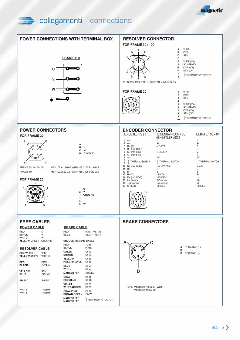
collegamenti |connections
A V RIFB COSC SENDE V RIF (0V)F SCHERMOG COS (0V)H SEN (0V)IJ } THERMOPROTECTOR
1 V RIF2 COS3 SEN45 V RIF (0V)6 SCHERMO7 COS (0V)8 SEN (0V)910 } THERMOPROTECTOR
POWER CONNECTIONS WITH TERMINAL BOX RESOLVER CONNECTORFOR FRAME 30÷100
FOR FRAME 20
AI
H
G
F
B
C
DJ
E
TYPE: MS 4102 A 18-1P WITH MS 3106 A 18-1S
POWER CONNECTORSFOR FRAME 30
A UB VC WD GROUND
A D
B C
FRAME 30, 40, 50, 60: MS 4102 A 18-10P WITH MS 3106 F 18-10S
FRAME 80: MS 4102 A 22-22P WITH MS 3106 F 22-22S
FOR FRAME 20
1 U2 V
GROUND456 W
1 A+2 A-3 R+ (Z)4 D- (ref. COS)5 C+ (ref. SIN)6 C- (ref. SIN) 7 0V89
10 Up +5V (Vdc)11 B+12 B-13 R- (Z)14 D+ (ref. COS)15 0V sensor16 +5V sensor17 SHIELD
A+A-+ DATA
+ CLOCK
0V
Up +5V (Vdc)B+B-- DATA- CLOCK0V sensorUp sensorSHIELD
A+A-ZUVV-0V
+ VdcB+B-Z-U-W-WSHIELD
} THERMAL SWITCH
FREE CABLESPOWER CABLERED UBLACK VWHITE WYELLOW-GREEN GROUND
RESOLVER CABLERED-WHITE VRIFYELLOW-WHITE VRIF (0)
RED COSBLACK COS (0)
YELLOW SENBLUE SEN (0)
SHIELD SHIELD
WHITE THERM.WHITE THERM.
BRAKE CABLERED POSITIVE (+)BLUE NEGATIVE (-)
ENCODER EF36/49 CABLE
RED +VdcBLACK 0 Volt
GREEN Ch ABROWN Ch A-
YELLOW Ch BPINK or ORANGE Ch B-
BLUE Ch ZWHITE Ch Z-
MARKED “S” SHIELD
GRAY Ch URED-BLUE Ch U-
VIOLET Ch VWHITE-GREEN Ch V-
GRAY-PINK Ch WBROWN-GREEN Ch W-
MARKED “T” } THERMOPROTECTORMARKED “T”
BRAKE CONNECTORS
A NEGATIVE (–)BC POSITIVE (+)
CA
B
TYPE: MS 3102 R10 SL-3P WITHMS 3106 F10 SL-3P
5
6
42
1
1110
1
1213
14 15
1617
2
3
45
67
8
9
THERMAL SWITCH} THERMAL SWITCH}
1110
1
1213
14 15
1617
2
3
45
67
8
9
ENCODER CONNECTORHENGSTLER S 21 HEIDENHAIN EQN / EQI ELTRA EF 36 - 49
HENGSTLER AD36
FRAME 100
U
V
W
6 | BLQ
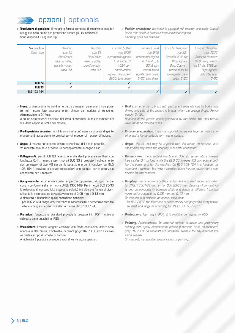
opzioni | optionals> Trasduttore di posizione: il motore è fornito completo di resolver o encoder
alloggiato nello scudo per protezione contro gli urti accidentali. Sono disponibili i seguenti tipi:
> Position transducer: the motor is equipped with resolver or encoder locatedinside rear shield to protect it from accidental impacts. Following types are available:
> Freno: di stazionamento e/o di emergenza a magneti permanenti incorpora-to nel motore lato accoppiamento; chiude per caduta di tensione.Alimentazione a 24 Vcc.A causa della potenza dissipata dal freno si consideri un declassamento del5% della coppia di stallo del motore.
> Predisposizione enconder: fornibile a richiesta può essere completa di giuntoe lanterna di accoppiamento previsti per gli encoder di maggior diffusione.
> Angus: il motore può essere fornito su richiesta dell’anello paraolio.Va montato solo se è previsto un accoppiamento in bagno d’olio.
> Collegamenti: per il BLQ 23 l’esecuzione standard prevede cavi liberi conlunghezza 0.4 m, mentre per i motori BLQ 33 è previsto il collegamentocon connettori di tipo MS sia per la potenza che per il resolver; sul BLQ103-104 è prevista la scatola morsettiera con basetta per la potenza econnettore per il resolver.
> Accoppiamento: le dimensioni della flangia d’accoppiamento di ogni motoresono in conformità alla normativa UNEL 13501-69. Per i motori BLQ 23-33la tolleranza di concentricità e perpendicolarità tra albero e flangia si diver-sifica dalla normativa ed è rispettivamente di 0.08 mm e 0.13 mm.A richiesta è disponibile quale esecuzione speciale:- per BLQ 23-33 flangia con tolleranza di concentricità e perpendicolarità tra
albero e flangia in conformità alla normativa UNEL 13501-96.
> Protezioni: l’esecuzione standard prevede le protezioni in IP54 mentre arichiesta sono possibili in IP55.
> Verniciatura: i motori vengono verniciati con fondo epossidico (colore neroopaco o in alternativa, a richiesta, di colore grigio RAL7031) atto a riceve-re qualsiasi tipo di smalto di finitura.A richiesta è possibile prevedere cicli di verniciatura speciali.
> Brake: an emergency brake with permanent magnets can be built in thedriving end side of the motor; it brakes when the voltage drops. Powersupply: 24Vdc.Because of the power losses generated by the brake, the stall torquevalue must be derated of 5%.
> Encoder preparation: it may be supplied on request together with a cou-pling and a flange suitable for most encoders.
> Angus: the oil seal may be supplied with the motor on request. It isassembled only when the coupling is oil-bath lubrificated.
> Connections: the standard exection of BLQ 23 servomotors foreseefree cables 0.4 m long while the BLQ 33 foresee MS connectors bothfor the power and for the resolver. On BLQ 103-104 it is foreseen asstandard a terminal box with a terminal block for the power and a con-nector for the resolver.
> Coupling: the dimensions of the coupling flange of each motor accordingto UNEL 13501-69 norms. For BLQ 23-33 the tolerance of concentrici-ty and perpendicularity between shaft and flange is different from thenorm and is respectively 0.08 mm and 0.13 mm.On request it is available as special execution:- for BLQ 23-33 the tolerance of concentricity and perpendicularity betwe-en shaft and lange in according to UNEL13501-69 norm.
> Protections: Normally in IP54, it is available on request in IP55.
> Painting: Pretreatments for external surface of motor and preliminarypainting with epoxy bicomponent primer (lustreless black as standard;grey RAL7031 on request) are foreseen, suitable for any different fini-shing enamel.On request, it’s avaiable special cycles of painting.
Motore tipo Resolver Resolver Encoder ELTRA Encoder ELTRA Encoder Hengstler Encoder HengstlerMotor type size 15 size 21 type EF36 type EF49 type S21 type AD36
Sine-Cosine Sine-Cosine Incremental signals Incremental signals Sinusoidal 2048 ppr Absolute multiturnwave; 2 poles; wave; 2 poles; A, A and B, B A, A and B, B 1Vpp signals; (4096 rev.) positiontransformation transformation 1024 ppr; 2048 ppr; Sine/Cosine 1 on 31 bits; 8192 ppr
ratio 0.5 ratio 0.5 commutation commutation period absolute 1Vpp signals;signals; zero pulse; signals; zero pulse; waves/rev.; zero BiSS interface;
5VDC; Line driver 5VDC; Line driver pulse; 5VDC 5VDCBLQ 23 3 3
BLQ 33 3 3
BLQ 103-104 3 3 3 3

BLQ | 7
coppia continuativa (∆T=105K) in funzione della velocitàcontinuous torque (∆T=105K) versus speed
[Nm]1.2
0.9
0.6
0.3
0 2000 4000 6000 8000 [RPM]
BLQ 23 BLQ 33
L
ML
M S
[Nm]80
60
0 1000500 2000 [RPM]
BLQ 103 - BLQ 104
P
L
M
S40
20
1500
x
carico radiale ammissibile per una durata teorica del cuscinetto lato accoppiamento di 20000 oreadmitted radial load for 20000 hours, theoretical life of the shaft end bearing
10
max 2 E
X (mm)E
Fr
Fr = 2040 x C x kD
dove:Fr carico radiale in [N]C coppia del motore in [Nm]D diametro della puleggia in [mm]k fattore di tensione fornito dal costruttore
della puleggia e valutabile mediamente ink=1 per cinghie dentellatek=2.3 per cinghie trapezoidalik=3.8 per cinghie piane
Fr = 2040 x C x kD
where:Fr radial load in [N]C motor torque in [Nm]D pulley diameter in [mm]k tensile factor specified by pulley manufa-curer and corrisponding about to:
k=1 for toothed beltsk=2.3 for trapeizodal beltsk=3.8 for flat belts
0 20 x [mm]
BLQ 23 BLQ 33
5 10
F [N]500
375
250
125
2000 RPM
4000 RPM 6000 RPM8000 RPM
2000 RPM
4000 RPM 6000 RPM8000 RPM
<
<
0 80 x [mm]
BLQ 103 - BLQ 104
20 50
F [N]4000
2000
1000
1000 RPM
2000 RPM 3000 RPM
1500 RPM3000
<

8 | BLQ
BLQ 23
VERSION E: STANDARD EXECUTION (RESOLVER / ENCODER EF36)
252
POWERSIGNALS
56
Ø63
Ø5.5
136
L
B20
2.5
7
CABLES LENGHT 400 mm
SIGNAL CABLES POWER CABLES
CENTRE M3 UNI 9321
B
LENGHT
FREE CABLES
ML
133173
L153
193
QUOTASCONNECTORS
B141181
L161
201
Ø9
j6
10.2
3 h
9
56
57.5
Ø5.5
Ø63
2.5
7
20 B
L
Ø40
j6
2526/0
VERSION B: MOTOR WITH RADIAL MOUNTED CONNECTORS

BLQ | 9
BLQ 33
VERSION B: STANDARD EXECUTION (RESOLVER / ENCODER EF36)
QUOTAS
LENGHTSML
B157177197
L180200220
QUOTAS B-L INCREASES28 mm IN BRAKE VERSION
126
26
6732
35
70
20
Ø60
j6
2.5
7.5
23 B
L
BRAKE CONNECTOR IF REQUIRED POWER
SIGNALS
Ø5.5
Ø75
Ø11
j6
12.54
H9
CENTRE M4 UNI 9321
124.
5
2648.5
84
110.5 26
2521/A
VERSION C: MOTOR WITH ROTATABLE RIGHT ANGLE LINE CONNECTORS
VERSION D: MOTOR WITH RIGHT ANGLE MOUNTEDPANEL CONNECTORS (180° ADJUSTABLE)

10 | BLQ
BLQ 103/104
VERSION A: STANDARD EXECUTION (RESOLVER / ENCODER S21-EF49)
L
BLQ 103/104
QUOTAS
SMLPX
374419464
456
501546
509 591554 636
QUOTAS B-L INCREASES 45 mm IN BRAKE VERSION
B
L
B
20
82
4
58
60
Ø18
0 j6
70
BRAKE CONNECTOR IF REQUIRED
1.5131
HOLE POWER Ø33
5
SIGNALS
208
176
30X45°
75 146
Ø215
Ø14
TERMINAL BOX (90° ADJUSTABLE)
45
Ø42
k6
12 h
9
CENTRE M12 UNI 9321
2520/A

BLQ | 11
BLQ 103/104
VERSION A: STANDARD EXECUTION (RESOLVER / ENCODER S21-EF49)
D
T V h9
CENTRE d UNI 9321
Q
N
F
A
I
55(60 FOR BLQ 103/104-106)
P5 59
BRAKE CONNECTOR IF REQUIRED
POWER
R
SIGNALS
B
TERMINAL BOX (90° ADJUSTABLE)
79 C
G
E
M
K
L
O
AIR INLET
AIR OUTLET
N M K I A F D V T d P B L O C R E G QQUOTAS
QUOTAS B-L INCREASES 45 mm IN BRAKE VERSION
BLQ 103/104
S
MLPX
180 215 14 4 20 82 42k6 12 45 M12 70 131 146 99 208 236 312
468513558603648
550595640685730
2530/A
MAGNETIC S.p.A.
via del Lavoro, 7
I-36054 Montebello Vicentino (VI)
tel. +39 0444 649399
fax +39 0444 440495
www.magnetic.it
[email protected] I00120/I - 10/2012
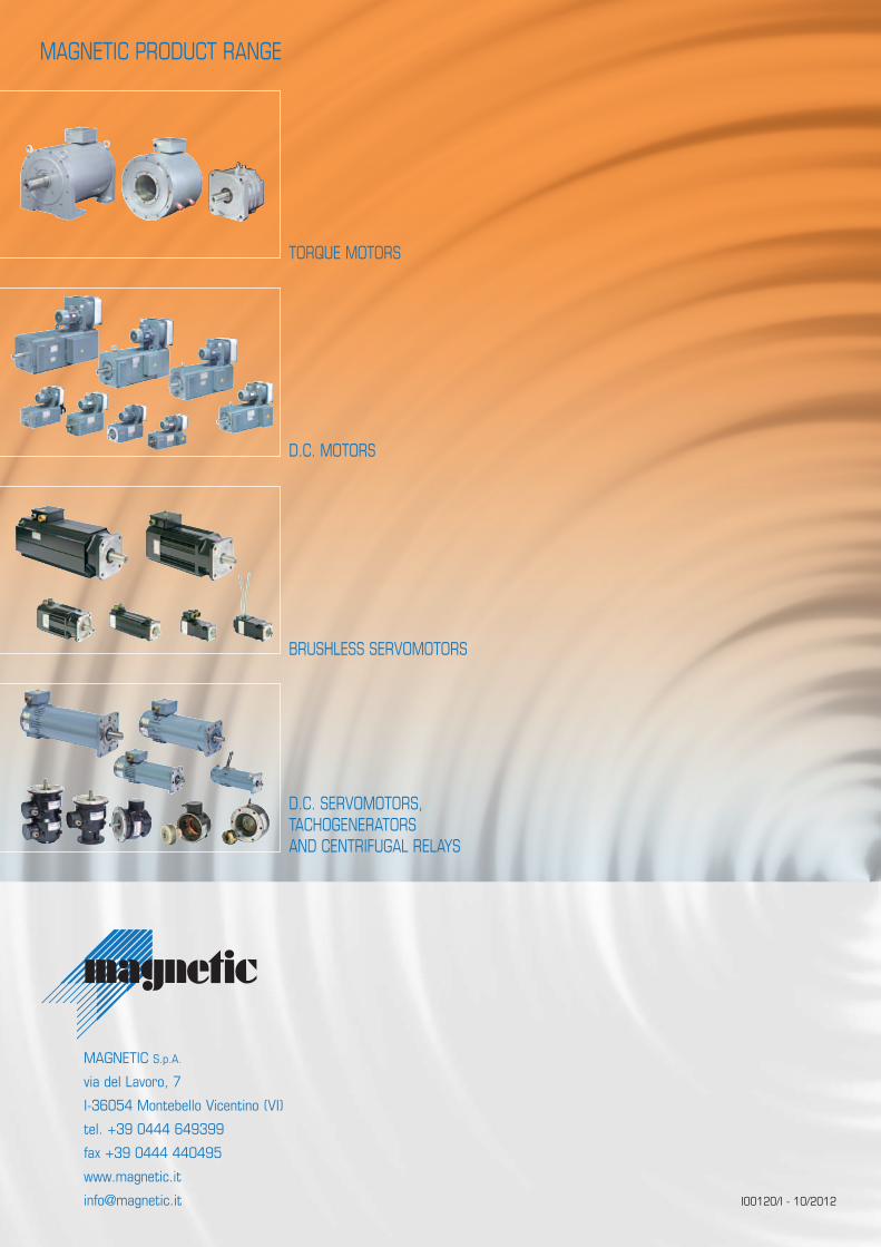
MAGNETIC PRODUCT RANGE
TORQUE MOTORS
D.C. MOTORS
BRUSHLESS SERVOMOTORS
D.C. SERVOMOTORS, TACHOGENERATORSAND CENTRIFUGAL RELAYS