section.wizard - bentley...section 1 introduction - geometric section properties - section.wizard 3...
TRANSCRIPT

Z Research Engineers
Section.wizard Creation of Sections and Calculation of their Geometric Properties
U S E R ’ s G U I D E

Section.wizard is a proprietary computer program of Research Engineers Intl. (REI), a division of netGuru, inc. California, U.S.A. Although every effort has been made to ensure the correctness of this program, REI will not accept responsibility for any mistake, error or misrepresentation in or as a result of the usage of this program. The User’s Guide contains description for the performance capability of the program packet for the creation of section forms and calculation of their geometric properties.
VERSION 4.0 Copyright© Research Engineers (Divisions of netGuru, Inc.). All Right Reserved
Published December, 2004

C o n t e n t s
INTRODUCTION ................................................................................................................................1 COORDINATE SYSTEM........................................................................................................................3 CALCULATED PROPERTIES.................................................................................................................3 FILES CREATED BY THE PROGRAMS ..................................................................................................4 COMMON CONTROL ELEMENTS.........................................................................................................5 SETTING UP ........................................................................................................................................5
Units of Measurement...................................................................................................................6 Miscellaneous Settings .................................................................................................................7 Stress Scale ...................................................................................................................................9 Profile Database...........................................................................................................................9
MENU ...............................................................................................................................................10 STATUS BAR.....................................................................................................................................12 TOOLBAR..........................................................................................................................................13
New Section.................................................................................................................................13 Open Section ...............................................................................................................................14 Save Section ................................................................................................................................15 Preview .......................................................................................................................................15 Create Standard Section.............................................................................................................16 Show Coordinate Axes................................................................................................................17 Show Grid ...................................................................................................................................17 Show Principal Axes ...................................................................................................................17 Show Center of Gravity ..............................................................................................................17 Shear Center ...............................................................................................................................17 Calculate Section Properties ......................................................................................................18 Stress Field .................................................................................................................................18 Zoom In and Zoom Out...............................................................................................................20 Create Report..............................................................................................................................21
FREESKETCH ...................................................................................................................................23 MOUSE CURSOR ...............................................................................................................................23 ENTER SECTION ...............................................................................................................................24 SET OVERALL DIMENSIONS .............................................................................................................24
Coordinate Grid..........................................................................................................................25 Enter External Contour ..............................................................................................................26 Edit External Contour ................................................................................................................27 Enter Internal Contour ...............................................................................................................27 Delete Internal Contour..............................................................................................................28 Multiple Copies of Internal Boundaries.....................................................................................29 Parametric Holes........................................................................................................................31
SECTION 1
SECTION 2

CONTENTS Section.wizard – USER’s GUIDE
ii
Enhanced Moving Vertices Command .......................................................................................33 Smooth Angle ..............................................................................................................................34 Shift Origin .................................................................................................................................36 Move Selected Nodes ..................................................................................................................36 Edit Node Coordinates ...............................................................................................................36 Unlimited Redo ...........................................................................................................................37 Delete Vertices............................................................................................................................38 Parametric Sections....................................................................................................................39 Auto-Dimension Tool..................................................................................................................41 New parametric sections including channels and rectangular tubes ........................................41 Import CAD Files .......................................................................................................................41 Enhanced import of DXF and DWG files...................................................................................42 Create sections from the standard databases ............................................................................42
SECTION BUILDER .........................................................................................................................45 MOUSE CURSOR ...............................................................................................................................46 SECTION ELEMENT DIALOG BOX.....................................................................................................47 SELECT PROFILE DIALOG BOX ........................................................................................................48 ELEMENT INFORMATION ..................................................................................................................49 ELEMENT ORIENTATION ..................................................................................................................49 OPERATIONS.....................................................................................................................................51
Shift Origin .................................................................................................................................51 Copy Element..............................................................................................................................52 Element Shift / Rotate .................................................................................................................53 Delete Element............................................................................................................................53 Unlimited Redo ...........................................................................................................................54 Viewing Element Properties .......................................................................................................55
ASSEMBLY HISTORY ........................................................................................................................56 ASSEMBLING SECTIONS ...................................................................................................................57
Including Element in Compound Section ...................................................................................57 Setting the First Element ............................................................................................................58 Join Node Method of Assembly ..................................................................................................59 Set Node Method of Assembly ....................................................................................................61 Join Line Method of Assembly....................................................................................................62
INTERSECTION OF SECTION ELEMENTS ...........................................................................................64 EXAMPLES OF ASSEMBLY ALONG A LINE .......................................................................................65
Dynamically Changing Elements ...............................................................................................70 Extra connection points for standard sections...........................................................................72 Auto-dimension Tool...................................................................................................................72 Error in calculating plastic section modulus for Tee sections...................................................73
SEZAM – SELECTION OF EQUIVALENT SECTIONS ............................................................75 SELECTION RESULTS........................................................................................................................76 RUN SECTION BUILDER....................................................................................................................77 RUN FREESKETCH ............................................................................................................................77
APPENDIXES.....................................................................................................................................79 DEFINITIONS OF GEOMETRIC PROPERTIES.......................................................................................79
Moments of Inertia......................................................................................................................79
SECTION 3
SECTION 4
SECTION 5

CONTENTS Section.wizard – USER’s GUIDE
iii
Principal Moments of Inertia, Angle of Principal Axes.............................................................79 Radii of Inertia............................................................................................................................80 Resisting Moments ......................................................................................................................80 Radius of Gyration......................................................................................................................81 Torsional Rigidity .......................................................................................................................81 Shear Center ...............................................................................................................................82 Section Areas at Shear................................................................................................................83 Plastic Resisting Moments..........................................................................................................84 Sectorial Properties ....................................................................................................................84 Normal Stress..............................................................................................................................85
FILE FORMAT ...................................................................................................................................85 ADDING PARAMETRIC SECTIONS.....................................................................................................87 SERVICE FUNCTIONS........................................................................................................................92
Formula Calculation ..................................................................................................................92 Unit Conversion..........................................................................................................................94
PROGRAM INTERFACE......................................................................................................................95 Using Section Builder Files........................................................................................................95 Using Freesketch Program Files................................................................................................97
EXPORTING DATA ..........................................................................................................................100 Section Builder and Freesketch................................................................................................100 Sezam ........................................................................................................................................101 Add selection of measure units for the export to STAAD.........................................................104
LIST OF METAL-ROLLED PROFILE ASSORTMENTS SUPPLIED WITH STRUCTURE.WIZARD...........105 Assortment of Cheliabinsk Steel Plant (Cheliabinsk Metal Manufacturers)...........................105 GOST.........................................................................................................................................105 Reduced GOST Assortment ......................................................................................................106 Old Assortments........................................................................................................................106 ASTM.........................................................................................................................................107 British Steel Sections ................................................................................................................107 British Standard Sections .........................................................................................................107 Overseas Shapes .......................................................................................................................108 Arbed.........................................................................................................................................108 OTUA ........................................................................................................................................109 DIN............................................................................................................................................110


Introduction Section.wizard consists of three applications, Section Builder, Freesketch and Sezam. All the programs operate under Windows 32 bit operating systems and place no special requirements upon computer configuration. User interface elements do not differ from the majority of other programs operating in the Windows environment.
Section Builder (Builder) is for creating arbitrary compound sections from steel rolled shapes and plates, as well as calculating their geometric properties.
The Freesketch program is for creating arbitrary sections, as well as calculating their geometric properties using solid rods theory.
The Sezam program is for finding equivalent sections (box, I-beam or channel), approximating the arbitrary section according to its geometric properties set by the user.
All the programs contained in Section.wizard are integrated with each other and with STAAD.Pro. In particular, it is possible to call one program from another and in some cases the data transfers from one program into another. The diagram of possible interrelations is shown in Fig. 1, where .SEC, .CNS, .CON are file format designations.

SECTION 1 Section.wizard - Geometric Section Properties - INTRODUCTION
2
STAAD
.SEC Import .CNS
.SEC .CNS
Export .CON
.CON
Section
Builder
.SEC
.CNS
Freesketch
Open Save
Open Save
.SEC .SEC .CNS .CNS
.CON .CON
.SEC
Sezam .CON
Open Save
.SEC .CNS .SEC .CON
Fig. 1. The diagram of program integration

SECTION 1 INTRODUCTION - Geometric Section Properties - Section.wizard
3
Coordinate System The right hand Cartesian coordinate system (X, Y, Z) is used. The x-axis is the beam’s longitudinal axis directed from the drawing plane toward an observer.
The z-axis is the vertical axis directed upwards in the drawing. The y-axis is the horizontal axis with the positive direction to the right.
Calculated Properties When designing a section, Section Builder calculates:
cross-sectional area A moments of inertia, Iy and Iz, about central axes parallel to the Y and Z
axes of the right hand Cartesian coordinate system radii of inertia, iy and iz, about the same axes moment of inertia at free torsion, It coordinates of the center of gravity angle of inertia of the principal central axis (the angle, α, between the U
and Y axes) maximum Iu and minimum Iv moments of inertia maximum iu and minimum iv radii of inertia maximum Wu+ and minimum Wu-resisting moments about the U-axis maximum Wv+ and minimum Wv- resisting moments about the V-axis radius of gyration from U-axis along the positive (au+) and negative (au-)
directions of V-axis radius of gyration from V-axis along the positive (av+) and negative (av-)
directions of U-axis In addition to those mentioned above, the Freesketch program calculates the following section properties:
section perimeters: total P, external Pe and internal Pi conditional cut-off areas, Av,y, Av,z moments of inertia about the system within which the section has been
created coordinates of the shear center sector properties: the sector moment and bimoment

SECTION 1 Section.wizard - Geometric Section Properties - INTRODUCTION
4
Section Builder does not calculate all the geometric properties in comparison with the Freesketch program. To calculate properties such as the flexural center position or sectorial characteristics, a solution of Laplacian differential equations is required on the section area with boundary conditions on the boundary line. These depend on whether this or another portion of the boundary line is a part of the external contour or whether it belongs to the internal hole. If sections have been created using Section Builder, in many cases it is unclear what the boundary line (external or internal) of the contour section is. That is why, in particular, the moment of inertia at free torsion is approximately determined as the sum of moments of inertia of the free torsion of profiles composing the section.
Geometric properties are usually calculated considering the section as continuous, ignoring the pliability of connecting grates and/or plates.
It should be noted that in the case of a section with equal moments of inertia (Iy = Iz), the angle α is undefined. The axes shown on the screen are accidental to some extent, since in the case considered, the ellipse of inertia degenerates into a circle of inertia (iy = iz = iu = iv) so any orthogonal couple of the central axes can be named as the principal axis.
The calculation of geometric properties is not the end in itself. It is assumed the calculation results will be used during further research of the stressed-strained state, in particular, while setting the initial data in a structural analysis program. The structural analysis program can be used to calculate the rigid characteristics of buildings and constructions and their elements. The Freesketch and Section Builder programs obtain the fields of normal stresses if internal forces in the section have been set.
Files Created by the Programs The Freesketch program creates, saves and reads files in two different file formats (with the CNS and CON extensions).
The CNS format is the internal format and has a relatively complicated structure. This format saves and reads the information about a section form as well as additional user defined settings such as grid parameters.
The CON format has a simple structure and is designed to exchange data with other applications.

SECTION 1 INTRODUCTION - Geometric Section Properties - Section.wizard
5
Section Builder creates, saves and reads files in the SEC file format. This file format stores information about the elements which compose the section and their mutual position. The Sezam program can read files both in the Section Builder (SEC) format and in the Freesketch (CNS) format.
Common Control Elements The different programs in Section.wizard have many common control elements. These common elements are described in this chapter. Each subchapter has the following table.
The sign “ • “ in the first cell means that the given action (option) is related to Section Builder, in the second cell to Freesketch and in the third cell to the Sezam program.
Setting Up The Settings dialog box is multi-tabbed.
Fig. 2

SECTION 1 Section.wizard - Geometric Section Properties - INTRODUCTION
6
Units of Measurement
The Units of Measurement tab (Fig. 2) is intended for setting the units, which describe angular (Angles) and linear (Sizes of Sections) dimensions, as well as results of the section analysis (Properties of Sections), forces and moments. The units are selected from relevant lists. For moments separate force and length length units may be defined using the button. The number of significant digits (number of decimal digits) is adjusted using the and buttons. The exponential form of a number is set with the button.
When adjusting the number of significant digits, note that this parameter also affects the operation of changing the distance between section points.
Fig. 3 Units of Measurement tab

SECTION 1 INTRODUCTION - Geometric Section Properties - Section.wizard
7
Miscellaneous Settings
The following settings can be adjusted on the Misc tab (Fig. 3):
message output language; report handling mode (review, print) report type (type of RTF file) report paper size (for printing) setting style and size of screen font name of the file containing report column headings Open Last Document option while the program is loading
Besides those mentioned above, the following options are available in the Freesketch program:
number of nodes on the full circle while plotting contours and rounding-off angles (Circle)
cursor snap to grid nodes Show Nodes option in the contour
The message output Language group determines the language in which the information is represented.
The Preview/Edit mode or Print mode can be selected for handling report documents.
If Preview/Edit is selected, one can view and edit the text of the report after pressing the Report button in any working window. An application associated with the RTF extension (e.g. Word/Pad or MS Word) is launched for this purpose. There are some differences between the RTF file format used by the MS Word v.7 and the one used by the Word 97 application. Therefore, Section.Wizard offers the option to choose the type of RTF file in the Report Type group.
If the Print radio button in the Report group is selected, the report will be printed in the format specified.

SECTION 1 Section.wizard - Geometric Section Properties - INTRODUCTION
8
Report Type specifies the RTF file type, which depends on the application associated with the RTF file (MS Word v.7, WordPad or MS Word 97). The correct representation of an assembled section can be attained only if the MS Word 97 option is used. MS Word v.7 contains some features that do not allow for representation of this type of graphical data.
Paper Size sets the paper size used when printing the report. The paper size is selected from a list.
The Font button is used to set the style and size of the displayed font. It opens a standard window where a font style and font size are selected. This font is used for representing information in the working area (numbers of supporting nodes, indices of axes, etc.), including rulers in Section Builder.
Column Headings allows you to select the name of a RTF file containing column headings, enabling the user to create and modify the file.
Apart from the settings mentioned above there are options on this tab whereby modes of automatically opening the last project while loading the program, snapping nodes to the next coordinate grid point and the visualization of nodes in a contour can be set. These options belong to the Freesketch program.
Fig. 4 Misc. tab of the Settings dialog box.

SECTION 1 INTRODUCTION - Geometric Section Properties - Section.wizard
9
Stress Scale
The Stress Scale tab (Fig. 4) facilitates choosing colors to depict the compressed and elongated parts of a section while viewing normal stress fields. The color scale will be more or less ‘smooth’ depending on the number of intervals specified in Quantity of Intervals.
Fig. 5 Stress Scale tab of the Settings dialog box
Profile Database
The Standards dialog box (Fig.5) is used to select metal-rolling assortment standards with the help of which a section is assembled. The left list contains the standard names included in the program. The right list contains the standards required for the current section assembly. The shift of selected standards from

SECTION 1 Section.wizard - Geometric Section Properties - INTRODUCTION
10
the left list into the right list and vice versa is executed with the Add button and the Remove button accordingly.
The standards placed in the right list can be arranged in any order. This is the order in which they will be displayed in the Standards list of the Element Selection and Standard Section dialog boxes. The Up and Down buttons are used to shift a selected standard upward or downward in the list.
Fig.6 Standards dialog box
Menu The menus of the Section Builder and Freesketch programs are located in the upper part of the window and contain five items, File, Edit, Settings, Service and Help.
The File menu includes the following items:
New – creates a new section (hot key combination CTRL-N) Open – opens a previously created section (hot key combination CTRL-O) Save – saves the assembled section (hot key combination CTRL-S) Save as…– saves the assembled section (file) with a different name Report – creates a report containing section properties

SECTION 1 INTRODUCTION - Geometric Section Properties - Section.wizard
11
Calculate – calculates section properties Stress Fields – creates normal stress fields Parametric Sections – creates a section based on the set of prototypes Selection of Equivalent Section – activates the Sezam program designed
for selecting equivalent sections (box, I-beam or channel), which approximate an arbitrary section created by the user according to geometric properties.
The Edit menu of the Freesketch program contains the following items:
Cancel – cancels the last operation Overall Dimensions – sets a sections overall dimensions External Contour – provides for creating and editing the external
contour of a section Internal Contour– provides for creating and editing the holes in an
arbitrary form, selected as a polygon Delete Internal Contour – deletes the selected internal contour Create Round Hole – creates a round hole with the radius set using the
mouse Create Round Hole with Specified Radius– generates a round hole with
the radius given in an edit box Smooth Angle… – smoothes the selected angle with am arc of a given
radius Origin of Coordinates… – shifts the origin of a sections coordinate
system. The Edit menu of the Section Builder program provides options to delete a selected element from the current section, to change the location of an element in a section, to shift the origin of coordinates and to copy selected elements.
The Settings menu includes the following items:
Preferences – calls a dialog box containing setup values Grid Options — allows you to specify dimensional grid spacing Grid — shows a dimensional grid in the working area Coordinate Axes — shows coordinate axes for the section Principal Axes — shows principal axes of inertia for the section

SECTION 1 Section.wizard - Geometric Section Properties - INTRODUCTION
12
Center of Gravity — shows the location of the center of gravity for the section
Zoom In — zooms in the section view in the working area Zoom Out — zooms out the section view shown in the working area.
This operation is only available after the view has been zoomed in. Normal Stress Field —draws a normal stress field in a section in
accordance with internal forces specified by the user.
The Service menu contains a link to the standard Windows Calculator, the scientific calculator and a program for converting units.
The Service menu allows access to the reference information.
Status Bar
The Status Bar (Fig.6) contains three fields: Overall Dimensions, Current Cursor Position, and Distance. The Overall Dimensions field shows the section’s overall dimensions. The Current Cursor Position field shows the coordinates of the cursor. These change as the mouse is moved. The Distance field displays the distance between two points of a section when in the measuring mode.
Fig. 7 Status Bar

SECTION 1 INTRODUCTION - Geometric Section Properties - Section.wizard
13
Toolbar Upon clicking a button in the toolbar, the corresponding process or command is activated. Henceforward, the term clicking means the following sequence: pointing at a desired object (in this case a button) and pressing the left mouse button.
New Section
The New Section icon is used to prepare the program to create a new section. Upon selecting this icon, the program window is set to the starting stage. If the current section was modified but not saved, a message is shown prompting to save it.
Fig. 8 Message window

SECTION 1 Section.wizard - Geometric Section Properties - INTRODUCTION
14
Open Section
The Open Section icon allows you to load a previously assembled section. After the operation is activated a standard Windows dialog box containing files (the CNS or CON extensions in Freesketch, or the SEC extension in Section Builder) is shown. As in the previous case, a save prompt is shown if the current section was modified but not saved.
Fig. 9 Open Section dialog box

SECTION 1 INTRODUCTION - Geometric Section Properties - Section.wizard
15
Save Section
The Save Section icon allows section data to be saved in a file. A standard Window dialog box opens where a file name is specified.
Fig. 10 Save Section dialog box
Preview
Preview allows the section to be viewed in the Section Builder window without active elements. When a section is being composed, the active element is always highlighted in the section. The Section Element window is closed and the deletion and shift operations become inaccessible.

SECTION 1 Section.wizard - Geometric Section Properties - INTRODUCTION
16
Create Standard Section
Create Standard Section allows you to create an initial section in the form of a compound section using a set of prototypes. A prototype selection and compound section settings are found in the Section dialog box, which appears after initializing the Create Standard Section function.
In the Select Profile group one can choose structural steel sections (the Standards group), whereby a required section will be selected. Only those standards used which were included into the Add tab on the Standard Section tab of the Settings dialog box are used.
Specify the group of structural steel profiles of one type (e.g. I-beams, channels, angles, etc.) from the cross section types. The selected cross-section type determines the table of accessible profile groups. For example, if the first section type is selected, only Equal Angles and Unequal Angles are accessible.
The Section tab allows you to select a specific profile, which will be used in the element cross-section.
Fig. 11 Section dialog box

SECTION 1 INTRODUCTION - Geometric Section Properties - Section.wizard
17
Show Coordinate Axes
This icon maps the axes of the main coordinate system onto the working area.
Show Grid
The Show Grid icon maps a grid onto the working area. Grid spacing is defined using the Grid Spacing function from the Settings menu.
Show Principal Axes
The Show Principal Axes icon maps the principal axes of inertia of the designed section onto the working area.
Show Center of Gravity
This icon maps the location of the center of gravity of the designed section onto the working area.
Shear Center
This icon maps the location of the flexural center of the designed section onto the working area of the Freesketch program.

SECTION 1 Section.wizard - Geometric Section Properties - INTRODUCTION
18
Calculate Section Properties
This operation carries out a calculation of geometric and rigid properties for the section and a dialog box appears where these properties are presented. Values of the properties are shown with the accuracy specified and in the terms selected for the current section. Refer to the Units of Measurement chapter for further information on specifying these values.
Fig. 12. Basic Geometry Dialog Box
Stress Field
The Stress Field icon displays internal forces acting in the section. In the Section Forces dialog box (Fig. 13) appears after the operation is activated. This is where you specify internal moments Mu and Mv acting about the principal axes as well as the internal longitudinal force applied to the center of gravity. Upon clicking OK an isofield of normal stress distribution is displayed.

SECTION 1 INTRODUCTION - Geometric Section Properties - Section.wizard
19
It is possible to display the stress value at any point in the section. To do this, place the mouse cursor at the corresponding point and press the left mouse button. Points with minimal and maximal stress values are always highlighted.
Fig. 13 Stress Field dialog box
Fig. 14 Normal Stress Field

SECTION 1 Section.wizard - Geometric Section Properties - INTRODUCTION
20
To change values of internal forces while a normal stress field is displayed, click in the working area with the right mouse button. The Section Forces dialog box (Fig.13) will appear where new values may be entered.
The Show areas only with the stresses above… option is used when a user wants to see only those fields of the section with absolute stress values which exceed the specified stress value. To use this option, enter a limiting stress value in the dialog box.
When moving the mouse cursor in this mode, the normal stress value at the position located by the mouse cursor is shown on the status bar.
The Freesketch program provides the option to plot the normal stress distribution diagram along a straight line specified. To do this, the following operations are to be carried out:
place the cursor at the first point of the straight line press and hold the Ctrl key press and hold the left mouse button. Keeping it pressed, move the cursor
to the second point then release.
Zoom In and Zoom Out
Zoom in on a section using the button. This causes the linear scaling of the section to be changed by +10%. The maximum scale pertains to a double enlarged view of the section. If the scale has been enlarged, scroll bars appear at the right and bottom edges of the working area, allowing you to change the position of the section in the working area.
Zoom out using the button.

SECTION 1 INTRODUCTION - Geometric Section Properties - Section.wizard
21
Create Report
The Create Report icon generates a report containing properties of the selected section in RTF (Rich Text Format) file format. After the file is created, an application associated with the RTF format is launched (e.g. MS Word or WordPad). Due to changes in the data format, it is important to create the RTF file in the correct format if MS Word is used. The MS Word version installed on the computer is specified when setting up Structure.wizard. Refer to the Misc subchapter.

SECTION 1 Section.wizard - Geometric Section Properties - INTRODUCTION
22

Freesketch The Freesketch program window (Fig. 15) contains a menu, toolbar, working area and status bar.
Fig. 15 General View of the Freesketch Program
Mouse Cursor All operations carried out in the working area are performed with the mouse cursor. The mouse cursor takes different forms when it is moved in the working area and when performing some commands. For example, when selecting an item from the menu or the toolbar, the mouse cursor takes the form of an arrow. When processing a command, the mouse cursor turns into an hourglass. If the mouse cursor is placed on the section contour, it is displayed as a cross with its center coordinates defining its current location. When placed on a node the cursor takes the form of a cross with a target.
toolbar menu
Status bar
working area

SECTION 2 Section.wizard - Geometric Section Properties - FREESKETCH
24
The distance between two points of a section can be found using the mouse cursor. To do this, place the mouse cursor on the first point and press the left mouse button. Keeping the mouse button pressed, move the mouse cursor to the second point. The distance between these two points will be shown in the right most section of the status bar. The accuracy of this value depends on the number of decimal digits specified in the Units of Measurement tab of the Settings dialog box. The coordinates of the mouse cursor’s current position are displayed in the middle section of the status bar.
Enter Section The sequence of operations for entering a section includes defining the following:
section dimensions coordinate grid parameters external section contour internal contours smoothing of angles (if required).
Set Overall Dimensions A section is set up on the coordinate grid, the dimensions of which are limited by the section dimensions. Section dimensions are specified in the Overall Dimensions dialog box (Fig. 16) using the units specified in the Units of Measurement tab of the Settings dialog box.
After leaving the Overall Dimensions dialog box, the rectangle limiting the section is displayed in the working area (Fig. 17). The section dimensions are shown in the first Status Bar field. After setting the external contour, the section dimensions are updated to their actual values
Fig.16 Overall Dimensions Dialog Box

SECTION 2 FREESKETCH - Geometric Section Properties - Section.wizard
25
Fig. 17 Representation of limits for a section on the working area
Coordinate Grid
Coordinate grid properties are set in the Grid Settings dialog box (Fig. 18). The horizontal grid spacing along the Y-axis and vertical grid spacing along the Z-axis are set within this dialog box, as well as the grid angle, in degrees, about the horizontal axis. The origin of the coordinate system coincides with the lower left corner of the rectangle which limits the sections overall dimensions.
Grid spacing and angle can be changed more than once while defining and/or editing the internal and external contours. This allows a grid to be set in accordance with the dimensions or position within the section contour. The grid rotates about the origin.
The grid is shown on the screen after the grid parameters have been defined (Fig. 19). The grid representation is switched on/off using the Grid button on the toolbar.
Fig. 18 Grid Parameters dialog box

SECTION 2 Section.wizard - Geometric Section Properties - FREESKETCH
26
Fig. 19 Grid representation on the working area
Enter External Contour
The Enter External Contour icon allows you to define the external shape of the section. This is done by clicking on the inflexion points of the polygon which define the contour, in consecutive order. Each inflexion point is fixed by clicking the left mouse button. The contour is closed by double clicking the left mouse button. The last inflexion point is connected to the first point and the section (Fig.20) is represented on the screen.
The mouse cursor can be set to snap to the nearest grid node. This is set in the Misc tab of the Settings dialog box. If the cursor is not set to snap to the grid, its current coordinates are shown in the second field of the status bar. If the Snap to Grid option is active, the coordinates of the nearest grid node are displayed in the status bar.
Fig. 20 Section representation in the working area

SECTION 2 FREESKETCH - Geometric Section Properties - Section.wizard
27
Edit External Contour
Clicking the External Contour icon after the external contour has already been defined allows you to edit the external contour. When editing, move the mouse cursor to any point on the contour. The mouse cursor changes to a cross for an arbitrary point or a cross with a target for an inflexion point. Click the left mouse button and “drag” the selected point to it’s new position. The new point is fixed by double clicking the left mouse button. Fig. 21 displays the contour of Fig. 9 after it has been edited.
Fig. 21 Section view after the external contour correction
Enter Internal Contour
Section.wizard provides three types of operations for defining internal contours:
setting a contour in the form of a closed polygon setting a contour in the form of a circle, using the mouse to define its
dimensions setting a contour in the form of a circle with a radius specified by entering
it into a dialog box. The sequence of operations for setting an internal contour in the form of a closed polygon is similar to those for entering an external contour. The internal contour is defined within the area of the external contour.
While defining a contour in the form of a circle with its dimensions set using the mouse, place the mouse cursor on the point in the section which defines the center of the circle. Keeping the left mouse button pressed, drag the cursor until the desired diameter is achieved. The contour (hole) is fixed upon double

SECTION 2 Section.wizard - Geometric Section Properties - FREESKETCH
28
clicking the left mouse button. If the right mouse button is pressed during this operation, the operation is aborted.
When defining a circle with a radius specified by entering it into a dialog box, the Round Hole Radius dialog box appears (Fig. 22) where the radius is specified. After defining the radius and clicking the OK button, use the mouse cursor to click on the center of the hole within the section.
An example of a section with internal contours is shown in Fig. 23.
Internal contours can not intersect an external contour.
Fig. 22 Radius of the circle hole dialog box
Fig. 23 Example of a section with selected internal contours of different forms
Delete Internal Contour
The Delete Internal Contour icon allows you to remove holes from the section. To delete an internal contour, click the Delete Internal Contour icon, place the mouse cursor on any point inside the contour and press the left mouse button.

SECTION 2 FREESKETCH - Geometric Section Properties - Section.wizard
29
Multiple Copies of Internal Boundaries
Purpose
This new feature allows the user to copy internal cutouts and paste them anywhere on the cross section.
Description
From the Edit menu, choose Multiple copy of internal contour and then select the method by which this contour will be selected.
Fig. 24
The two choices are Rectangle and Polygon. For Rectangle, click on the first corner of the rectangle and use the mouse to rubber band the window to

SECTION 2 Section.wizard - Geometric Section Properties - FREESKETCH
30
encompass the internal boundary/cutout to be copied. Click the left-mouse button to define the opposite corner of the rectangle.
Fig. 25
Drag the mouse to the position where the cutout is to be copied to. The coordinate locations can be viewed in the status bar at the bottom of the program. Click the left-mouse button again to confirm the copy.
Fig. 26
To copy an internal boundary using a polygon, select Polygon and click the outline of the polygon with the mouse. Double-click the mouse to close the polygon. The rest of the steps are the same as for the Rectangle selection.

SECTION 2 FREESKETCH - Geometric Section Properties - Section.wizard
31
Parametric Holes
Purpose
This new feature allows the user to create a circular or rectangular cutout and place it at an exact location on the cross-section.
Description
From the Edit menu, choose Parametric hole.
Figure 27

SECTION 2 Section.wizard - Geometric Section Properties - FREESKETCH
32
A dialog box will popup prompting for the center of the circle (if a circular hole is chosen) or the upper left hand corner of the rectangle (if the rectangular cutout is chosen). These two points are the Y and Z input items. If a circle is chose, provide the radius of the circle. If a rectangle is chosen, provide the width (B) along the Y axis and the height (H) along the Z axis.
Figure 28
Click on OK to see the new hole appear on the cross-section.

SECTION 2 FREESKETCH - Geometric Section Properties - Section.wizard
33
Enhanced Moving Vertices Command
Purpose
This new feature allows the user to graphically move the vertices of an existing cross-section.
Description
From the Edit menu, choose Move vertexes.
Figure 29
SECTION 2 Section.wizard - Geometric Section Properties - FREESKETCH
34
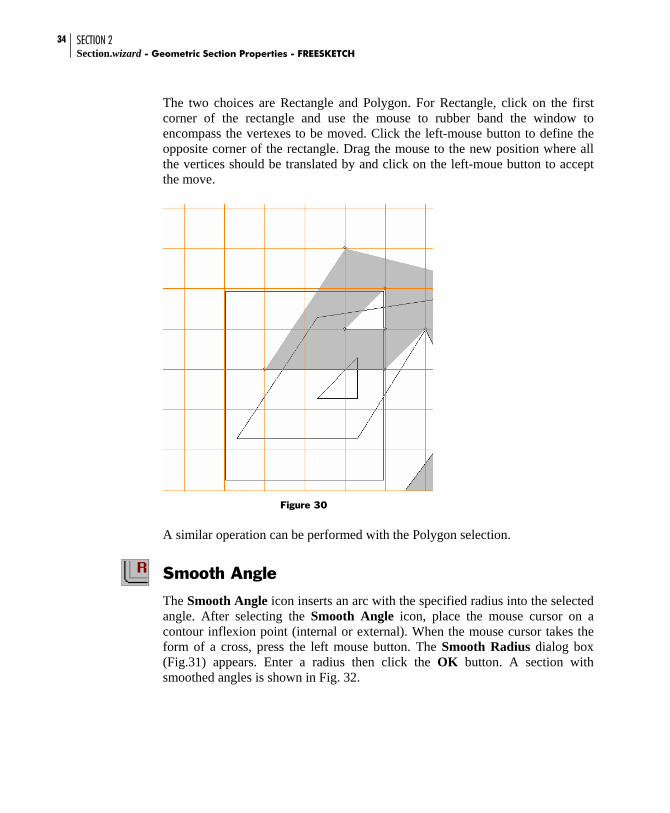
The two choices are Rectangle and Polygon. For Rectangle, click on the first corner of the rectangle and use the mouse to rubber band the window to encompass the vertexes to be moved. Click the left-mouse button to define the opposite corner of the rectangle. Drag the mouse to the new position where all the vertices should be translated by and click on the left-moue button to accept the move.
Figure 30
A similar operation can be performed with the Polygon selection.
Smooth Angle
The Smooth Angle icon inserts an arc with the specified radius into the selected angle. After selecting the Smooth Angle icon, place the mouse cursor on a contour inflexion point (internal or external). When the mouse cursor takes the form of a cross, press the left mouse button. The Smooth Radius dialog box (Fig.31) appears. Enter a radius then click the OK button. A section with smoothed angles is shown in Fig. 32.

SECTION 2 FREESKETCH - Geometric Section Properties - Section.wizard
35
The number of points (nodes) on the arc is defined in the Misc tab of the Settings dialog box. The minimum number of nodes on the full circle should not be less then 16. This is also true for nodes on internal contours.
While setting the number of nodes on a circle, note that their number considerably influences the calculation time, but at the same time, has a very small influence upon the result quality achieved. The calculations are based on the finite element method. Setting too many points on the arc can lead to the appearance of degenerated finite elements and finally to the calculation being interrupted.
Fig. 31 Smooth Radius dialog box
Fig. 32 Section view with smoothed angles
SECTION 2 Section.wizard - Geometric Section Properties - FREESKETCH
36
Shift Origin
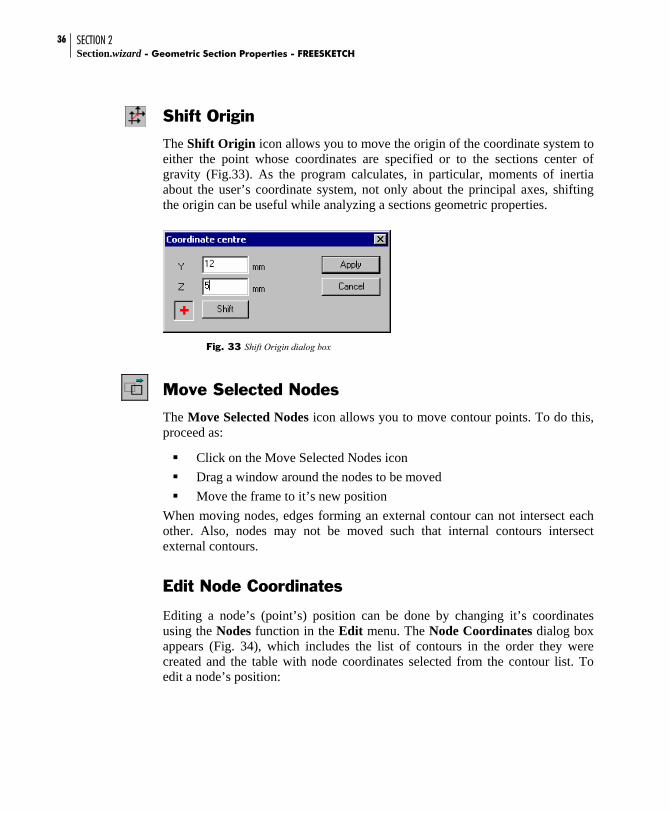
The Shift Origin icon allows you to move the origin of the coordinate system to either the point whose coordinates are specified or to the sections center of gravity (Fig.33). As the program calculates, in particular, moments of inertia about the user’s coordinate system, not only about the principal axes, shifting the origin can be useful while analyzing a sections geometric properties.
Fig. 33 Shift Origin dialog box
Move Selected Nodes
The Move Selected Nodes icon allows you to move contour points. To do this, proceed as:
Click on the Move Selected Nodes icon Drag a window around the nodes to be moved Move the frame to it’s new position
When moving nodes, edges forming an external contour can not intersect each other. Also, nodes may not be moved such that internal contours intersect external contours.
Edit Node Coordinates
Editing a node’s (point’s) position can be done by changing it’s coordinates using the Nodes function in the Edit menu. The Node Coordinates dialog box appears (Fig. 34), which includes the list of contours in the order they were created and the table with node coordinates selected from the contour list. To edit a node’s position:

SECTION 2 FREESKETCH - Geometric Section Properties - Section.wizard
37
select a contour from the list
change the node coordinates in the table press the Apply or OK button.
Fig. 34. Vertices coordinates dialog box
When moving nodes, edges forming an external contour can not intersect each other. Also, nodes may not be moved such that internal contours intersect external contours.
Unlimited Redo
Please see ‘Unlimited Redo’ under Section 3

SECTION 2 Section.wizard - Geometric Section Properties - FREESKETCH
38
Delete Vertices
Purpose
Vertices of a free-sketched polygon can be deleted graphically. The section will automatically redraw itself to compensate for the loss in a vertex.
Description
From the Edit menu, choose Delete vertexes. Several options will be presented in which vertexes can be deleted including selecting vertexes one by one and deleting all vertexes in a rectangular or polygonal region defined by the user.
Fig. 35

SECTION 2 FREESKETCH - Geometric Section Properties - Section.wizard
39
To delete one vertex at a time, select Single and click on a vertex to be deleted from the main graphical view. To delete a group of vertices, simply select Rectangle or Polygon. For Rectangle, click on the first corner of the rectangle and use the mouse to rubber band the window to encompass all vertexes to be deleted. Click the left-mouse button to define the opposite corner of the rectangle. All vertexes inside the rectangle will be deleted. To delete a group of vertices using a polygon, select Polygon and click the outline of the polygon with the mouse. Double-click the mouse to close the polygon. All vertexes inside the polygon will be deleted.
Parametric Sections
The standard set of parametric sections can be used to create sections. The Parametric Sections dialog box is called from the File menu option of the same name. The dialog box (Fig.36) includes the list of standard parametric sections, representation of a selected section model with the parameter symbols and a set of edit boxes for defining parameters.
A section is defined using the following actions:
select a required section from the list fill in the edit boxes according to the model press the OK button.
After clicking OK, the dialog box is closed and the created section is shown in the working area (Fig.37).
The section can be modified with operations from the toolbar. For example, the section contour profile can be changed, holes can be added, angles can be smoothed, etc.

SECTION 2 Section.wizard - Geometric Section Properties - FREESKETCH
40
The parametric section description language is used, with the help of which users are able to develop their own parametrical prototypes. The language description is given in the Appendix.
Fig. 36 Parametric Sections dialog box
Fig. 37 Resultant section

SECTION 2 FREESKETCH - Geometric Section Properties - Section.wizard
41
Auto-Dimension Tool
Please see ‘Auto-Dimension Tool’ under Section 3
New parametric sections including channels and rectangular tubes
Purpose
The pre-defined parametric sections under File->Parametric Sections now includes wide-flanges, channels and rectangular tubes.
Import CAD Files
A section can be imported from a CAD system in DWG or DXF file format.
The following types of graphic primitives are supported:
3DFACE SOLID TRACE LINE POLYLINE LWPOLYLINE ELLIPSE CIRCLE ARC
The section vertices must belong to one plane and the contour must be closed. These conditions are verified during import. If these conditions are not observed, the import is terminated and an error message appears.

SECTION 2 Section.wizard - Geometric Section Properties - FREESKETCH
42
Enhanced import of DXF and DWG files
Purpose
The import capabilities from AutoCAD DXF and DWG files have been improved significantly. There were problems with certain 3D faces that were not being imported in properly.
Create sections from the standard databases
Purpose
Standard steel sections from the steel databases provided in the program can now be inserted into the Free Sketch module.
Description
From the File menu, choose Rolled section.
Fig. 38

SECTION 2 FREESKETCH - Geometric Section Properties - Section.wizard
43
A dialog box prompting for the section to be inserted will popup. Select the section to be inserted. Only one standard section can be inserted from the Rolled Section option.
Fig. 39

SECTION 2 Section.wizard - Geometric Section Properties - FREESKETCH
44
Various steel section databases can either be removed or added to the Rolled Section list from the Settings->Preferences menu item. Select the tab marked Profile Databases and use the left and right arrow buttons to remove or add specific steel databases to be shown in the Rolled Section dialog box.
Figure 40

Section Builder The main items of the user interface are focused in two windows — Section Builder (Fig.41) and Section Element (Fig.42). The first window contains a working area where a section is created; menu, toolbar, and status bar are shown. The second window is a dialog box and contains control elements for selecting structural or lightweight steel sections, changing their position, controlling the assembly process, as well as providing an assembly history table.
Fig. 41. Section Builder window
Status bar
menu toolbar
working area

SECTION 3 Section.wizard - Geometric Section Properties – SECTION BUILDER
46
Fig. 42. Section Element dialog box
Mouse Cursor All operations carried out in the working area are performed with the mouse cursor. The mouse cursor takes different forms when it is moved in the working area and when performing some commands. For example, when selecting an item from the menu or the toolbar, the mouse cursor takes the form of an arrow. When processing a command, the mouse cursor turns into an hourglass. If the mouse cursor is placed on the section contour, it is displayed as a cross with its center coordinates defining its current location. When placed on a node the cursor takes the form of a cross with a target.
The distance between two points of a section can be found using the mouse cursor. To do this, place the mouse cursor on the first point and press the left mouse button. Keeping the mouse button pressed, move the mouse cursor to the second point. The distance between these two points will be shown in the right

SECTION 3 SECTION BUILDER - Geometric Section Properties - Section.wizard
47
most section of the status bar. The accuracy of this value depends on the number of decimal digits specified in the Units of Measurement tab of the Settings dialog box. The coordinates of the mouse cursor’s current position are displayed in the middle section of the status bar.
Section Element Dialog Box The Section Element dialog box is used to select structural sections from a steel table or specify lightweight sections, setting their orientation, as well as specifying rules for incorporating the selected element into the compound section. Most dialog box items are gathered into two groups, Operations and Assembly. The dialog box also contains Select Profile, Zoom In and Zoom Out buttons, an assembly history table, and a selected element representation field.
Fig. 43 Section Element dialog box
Selecting Section Button Element Information
Operation Group
Title of Element
Assembly Group
Assembly History Table
SECTION 3 Section.wizard - Geometric Section Properties – SECTION BUILDER
48
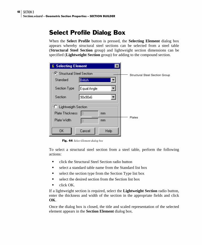
Select Profile Dialog Box When the Select Profile button is pressed, the Selecting Element dialog box appears whereby structural steel sections can be selected from a steel table (Structural Steel Section group) and lightweight section dimensions can be specified (Lightweight Section group) for adding to the compound section.
Fig. 44 Select Element dialog box
To select a structural steel section from a steel table, perform the following actions:
click the Structural Steel Section radio button select a standard table name from the Standard list box select the section type from the Section Type list box select the desired section from the Section list box click OK.
If a lightweight section is required, select the Lightweight Section radio button, enter the thickness and width of the section in the appropriate fields and click OK.
Once the dialog box is closed, the title and scaled representation of the selected element appears in the Section Element dialog box.
Structural Steel Section Group
Plates

SECTION 3 SECTION BUILDER - Geometric Section Properties - Section.wizard
49
If supporting nodes are not clear on the representation, the Zoom In button can be used. By pressing the button, the view is zoomed in by 10%. When the view is zoomed in, scroll bars are displayed in the representation field.
Element information The Element Information button is used to open a Section Element window where the selected element and its dimensions are displayed.
Fig. 45 Section Element window
Element Orientation Prior to its incorporation into the compound section, the selected element is oriented using commands from the Operation group. These commands are Rotate and Mirror. Each element in the assembly has supporting nodes which are used to incorporate the element into the section. The rotation is performed about the basic node. The rotation of an element by the angle specified in the Rotation Angle entry field is processed by pressing the Rotate button. A positive angle rotates counter clockwise. The locations of supporting and basic nodes are shown in Fig. 46.

SECTION 3 Section.wizard - Geometric Section Properties – SECTION BUILDER
50
a) angles (basic node 1) b) I-sections (basic node 10)
c) channels (basic node 1) d) O-sections (basic node 10)
e) plate section (basic node is located at the center of gravity)
f) T-section (base node1) g) Rectangular hollow sections (basic node is located at the center of gravity)
Fig. 46. Location of supporting and basic nodes in various type elements.
For angles and channels, the Mirror command is available.

SECTION 3 SECTION BUILDER - Geometric Section Properties - Section.wizard
51
Operations The following sections will describe the functions and tools available to edit certain parts of the current section.
Shift Origin
The Shift Origin icon allows you to move the origin of the coordinate system to either the point whose coordinates are specified or to the sections center of gravity (Fig.33). As the program calculates, in particular, moments of inertia about the user’s coordinate system, not only about the principal axes, shifting the origin can be useful while analyzing a sections geometric properties.
Fig. 47 Shift Origin dialog box

SECTION 3 Section.wizard - Geometric Section Properties – SECTION BUILDER
52
Copy Element
The Copy Element icon allows you to copy a selected element a given number of times with a definite spacing along the Y and Z directions. Select an element to be copied and press the Copy Element icon. Set the spacing along the Y and Z directions in the dialog box.
There is a copy operation result in Figure 49.
Fig. 48 Copy Element Dialog Box
Fig. 49 Copy Operation Result

SECTION 3 SECTION BUILDER - Geometric Section Properties - Section.wizard
53
Element Shift / Rotate
The Element Shift/Rotate icon allows you to shift, mirror and/or rotate the specified element. Shift and rotation settings are entered in the Element Shift/Rotation dialog box. The Mirror operation makes sense only for angles and channels and is carried out about the Z-axis.
Fig. 50 Element Shift/Rotate Dialog box
Delete Element
The Delete Element icon allows a selected element to be deleted from the section. To execute the operation, use the cursor to select the element to be deleted and press the Delete Element icon in the toolbar.
SECTION 3 Section.wizard - Geometric Section Properties – SECTION BUILDER
54
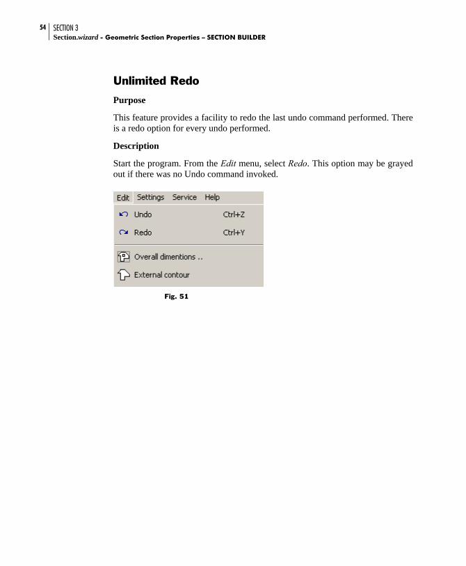
Unlimited Redo Purpose
This feature provides a facility to redo the last undo command performed. There is a redo option for every undo performed.
Description
Start the program. From the Edit menu, select Redo. This option may be grayed out if there was no Undo command invoked.
Fig. 51

SECTION 3 SECTION BUILDER - Geometric Section Properties - Section.wizard
55
Viewing Element Properties
Purpose
This facility makes it possible to display the dimensions and view the sectional property values of individual elements in a built-up section.
Description
Double click on any element in the main view. The dimensions of the element of the cross-section will be displayed. To view the actual properties of the element, simply click on the Properties button.
Fig. 52

SECTION 3 Section.wizard - Geometric Section Properties – SECTION BUILDER
56
Assembly History An assembly history table is located in the lower portion of the Section Element dialog box. All the elements included in the compound section are listed in the order in which they were added. The angle of rotation about the Y-axis of the general section coordinate system and indication of any activated Mirror commands are also shown.
A row of the table is selected by clicking on it with the mouse cursor. The corresponding element of the section becomes active; it is colored yellow in the Section Builder window. The following operations can be performed on the element described in the highlighted row. Click right mouse button and select one of the following from the pop-up menu (Fig. 54):
Shift, Rotate - replicates the Element Shift/Rotate command of the toolbar
Select Element - replicates the Select Section command, adding the section to the element without searching for it in a steel table or specifying lightweight section sizes.
Fig. 53 Assembly History Table
Fig. 54 Initiating processes per pop-up menu

SECTION 3 SECTION BUILDER - Geometric Section Properties - Section.wizard
57
Assembling Sections To include an element into the compound section, proceed as follows:
press the Select Section button select a structural section or enter lightweight section sizes in the Select
Element dialog box in the Operations group, set the orientation of the element in the section in the Assembly group, set a method of including the element into the
section and press the Add button.
Including Element in Compound Section
The operation of including an element into the compound section is performed in the Assembly group. Assembling means incorporating an element from the Section Element dialog box into a previously built element or relating it to a section node defined by Y and Z coordinates.
The following methods of assembly are accepted by Section Builder:
joining an elements supporting node to a supporting node of an element which is part of a section
joining an elements supporting node to a section node defined by Y and Z coordinates;
joining an element by coincidence of lines connecting two supporting nodes in the element being added and an active element of the section.
When using the two first two methods the section orientation specified in the Section Element dialog box is considered. When joining by a line, the orientation of an element is defined by the orientation of the lines used to join the elements. When the first element is being positioned, only the second method of assembly can be used.

SECTION 3 Section.wizard - Geometric Section Properties – SECTION BUILDER
58
Setting the First Element The first element is set using the following sequence of actions: 1] specify the first element of the designed section in the Section Element
dialog box (Fig. 55), e.g. American Standard Shapes S3×5.7 [1a] 2] select the Set Node radio button 3] from the list, select the number of the supporting node (e.g. No.2 [4]) used
for positioning the element at the a point with the specified coordinates. The supporting node is colored red in the section representation
5] specify the coordinates of the point at which the supporting node will be joined (e.g. Y=0, Z=0);
6] press the Add button.
Fig. 55 Sequence of actions for setting the first node of a section
1
1a
4
32
5
6

SECTION 3 SECTION BUILDER - Geometric Section Properties - Section.wizard
59
After the Add button is clicked, the positioned structural section is shown in the working area of the Section Builder window. Simultaneously, in the bottom of the Section Builder window, the positioned structural section is shown in the assembly history table, where the section is listed in the first row (Fig. 56).
Fig. 56 Result of setting the first element of a section
Join Node Method of Assembly
The assembly method allows a new element to be added into a section by joining the selected supporting node of the element to the selected supporting node belonging to an active element of the section. An active element is an element of a section to be joined by a new element. The active element can be selected by clicking on it with the mouse cursor in the working area or by highlighting it’s row in the assembly history table.
SECTION 3 Section.wizard - Geometric Section Properties – SECTION BUILDER
60
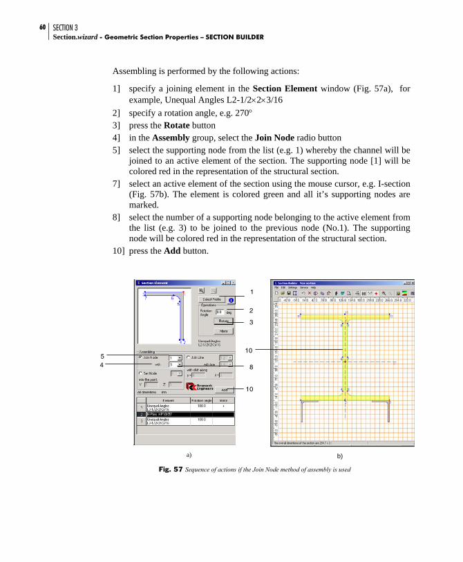
Assembling is performed by the following actions:
1] specify a joining element in the Section Element window (Fig. 57a), for example, Unequal Angles L2-1/2×2×3/16
2] specify a rotation angle, e.g. 270° 3] press the Rotate button 4] in the Assembly group, select the Join Node radio button 5] select the supporting node from the list (e.g. 1) whereby the channel will be
joined to an active element of the section. The supporting node [1] will be colored red in the representation of the structural section.
7] select an active element of the section using the mouse cursor, e.g. I-section (Fig. 57b). The element is colored green and all it’s supporting nodes are marked.
8] select the number of a supporting node belonging to the active element from the list (e.g. 3) to be joined to the previous node (No.1). The supporting node will be colored red in the representation of the structural section.
10] press the Add button.
a) b)
Fig. 57 Sequence of actions if the Join Node method of assembly is used
54 8
1
2
3
10
10

SECTION 3 SECTION BUILDER - Geometric Section Properties - Section.wizard
61
NOTE : If the Zoom In button is used, scroll bars are displayed in the structural section representation field of the Section Element window.
The section resulting from the assembly is shown in Fig. 58.
Fig. 58 Section resulting from assembly
The coordinate axes, the principal axes of inertia and the position of the center of gravity are shown in the drawing.
Set Node Method of Assembly
The Set Node method of assembly is described in the Section titled Setting the First Element. Additionally, it should be noted that an element can be joined to a point with specified coordinates, having been oriented as specified in the Section Element dialog box.

SECTION 3 Section.wizard - Geometric Section Properties – SECTION BUILDER
62
Join Line Method of Assembly
The Join Line method concerns the possibility of joining an element into the section using coinciding lines defined by selected pairs of nodes in the added element and the active element of the section. The first node of the added element’s line coincides with the first node of the line belonging to the active element.
It is possible to move the additional element. This is specified by shift components y, along the interface line belonging to the active element of the section, and z, perpendicular to the line. The interface lines remain parallel. This is convenient when inclined elements are added to the section.
The assembly is performed in the following order:
1] in the Section Profile window (Fig. 57a), specify an element, e.g. an angle with unequal flanges 25x16x3, which will be joined to the previously created section (Fig. 57b)
2] in the Assembly group, select the Join Line radio button 3] from the list, select the supporting nodes that define the line by which the
angle adjoins the active element of the section (e.g. 1-2). The line running between the specified nodes [4] will be colored red in the section representation.
5] select an active element from the section, for example a lightweight section. The element is colored yellow and supporting nodes are marked on it.
6] from the list, choose the supporting nodes that define the line that the new profile is to be positioned along (e.g. 1-4). The line running between the specified nodes [7] will be colored red in the section representation.
8] enter a shift value, e.g. 30 mm along the lightweight section (y), if desired 9] press the Add button. The resulting section is shown in Fig. 60.

SECTION 3 SECTION BUILDER - Geometric Section Properties - Section.wizard
63
a)
b)
Fig. 59. Assembly along a line
When assembling along a line, the following should be considered:
the additional element is positioned in the section in such a way that the first node of the assembly line coincides with the first node of the assembly line belonging to the active element of the section (if no shift had been specified);
shifting the added element is performed about the local coordinate axes yz with their origin being at the first node of the assembly line belonging to the active element of the section;
when the assembly is performed, control over the intersection of the added element with the section is carried out. If detected a message is issued.

SECTION 3 Section.wizard - Geometric Section Properties – SECTION BUILDER
64
Fig. 60 Section resulted from joining an angle
Intersection of Section Elements A message warning about the intersection of section elements is shown in Fig. 44. The information issued in the message window can be ignored (Yes) or the intersecting element can be removed from the section (No). In some cases the intersection occurs due to approximation errors when processing floating-point operations; there is no “pure” null, values of trigonometric functions are counted approximately. In these cases, which are possible if a rotation has been performed, answer Yes is recommended. The same answer is given if a user is aware of the intersection because the final setting of the element is intended to be done with the Shift, Rotate or Mirror operations.
Fig. 61 Message window

SECTION 3 SECTION BUILDER - Geometric Section Properties - Section.wizard
65
Examples of Assembly Along a Line Example 1: A section (Fig. 62) containing a lightweight section 10x100 mm (1) and four angles with unequal flanges 50x32x3 (2–5) is required.
Fig. 62 Designed section
Following are the operations to perform the assembly:
choose a lightweight section as the first element and set it into the designed section (ref. Setting the First Element for details) relating the node No.1 to X=0, Y=0
select an angle specify the Join Line operation set line with nodes 1–3 for the angle set line with nodes 1–4 for the lightweight section press the Add button (Fig. 63)
Fig. 63 Setting the first angle
press the Mirror button to change the orientation of the angle specify the Join Line operation for the angle with nodes 1–3 and the
lightweight section with nodes 4–1 press the Add button (Fig. 64)
3
1
4
5
2

SECTION 3 Section.wizard - Geometric Section Properties – SECTION BUILDER
66
Fig. 64 Setting the second angle
press the Mirror button to change the orientation of the angle specify the Join Line operation for the angle with nodes 1–2 and the
lightweight section with nodes 2–3 press the Add button; the angle will be positioned as shown in Fig. 65
Fig. 65 Position of the third angle after processing Add command
click on the positioned angle to make it active click on the Shift/Rotate Selected Element icon in the toolbar in the Rotate field of the Shift/Rotate Element dialog box (Fig. 68),
enter an angle of 270º in the Rotate field as a result, the angle will be positioned as shown in Fig. 66
Fig. 66 Position of the third angle after performing rotation by 270º
press the Mirror button to change the orientation of the angle

SECTION 3 SECTION BUILDER - Geometric Section Properties - Section.wizard
67
specify the Join Line operation for the angle with nodes 1–2 and the lightweight section with nodes 3–2
press the Add button; the angle will be positioned as shown in Fig. 67
Fig. 67 The net result after the fourth angle is set
Fig. 68 Shift/Rotate Element dialog box

SECTION 3 Section.wizard - Geometric Section Properties – SECTION BUILDER
68
Example 2:
A section (Fig. 69) containing an I-section S5x10 (1) and two channels (2–3) is required.
Fig. 69 Section designed
Following are the operations to perform the assembly:
choose an I-section as the first element set the inclination angle to 30º. Position the I-section into the designed
section relating to X=0, Y=0 select a channel press the Mirror button and change the orientation of the channel specify the Join Line operation set line with nodes 11–1 for the channel (note that the assembly line is
defined with the line running from node 11 to node 1) set line with nodes 4–8 for the I-section press the Add button (Fig. 70). Once the channel has been set a message
about the intersection with the I-section is issued (ref. Intersection of Section Elements for details). In this case, this is because the channel overlaps the curved parts of the I-section web. The intersection can be ignored in the example.

SECTION 3 SECTION BUILDER - Geometric Section Properties - Section.wizard
69
Fig. 70 The section after the first channel has been set
Press the Mirror button to change the orientation of the channel specify the Join Line operation for the channel with nodes 1–11 and the I-
section with nodes 5–9 press the Add button (Fig 71). In this case again the intersection of the
elements shall be ignored
Fig. 71 The section after the second section has been set
click on the positioned channel with the mouse cursor to make it active select the Rotate/Shift Selected Element icon from the tool bar in the Rotate field of the Shift/Rotate Element dialog box enter a 210º
angle of rotation as a result, the channel will be positioned as shown in Fig. 69 Section designed
SECTION 3 Section.wizard - Geometric Section Properties – SECTION BUILDER
70
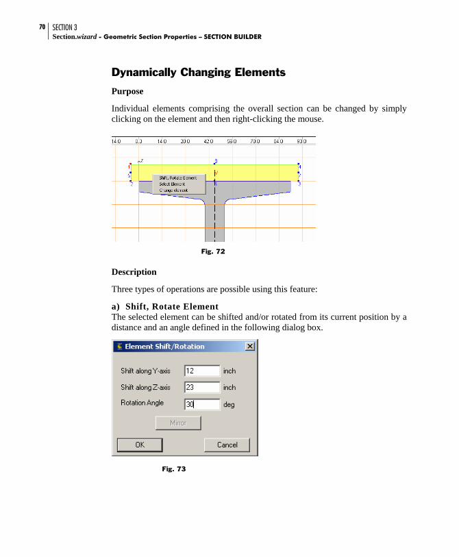
Dynamically Changing Elements
Purpose
Individual elements comprising the overall section can be changed by simply clicking on the element and then right-clicking the mouse.
Fig. 72
Description
Three types of operations are possible using this feature:
a) Shift, Rotate Element The selected element can be shifted and/or rotated from its current position by a distance and an angle defined in the following dialog box.
Fig. 73

SECTION 3 SECTION BUILDER - Geometric Section Properties - Section.wizard
71
All the vertices in the element will be moved and/or rotated by the amount specified.
b) Select Element Selecting the current element sets the current highlighted element (in yellow) in the Section Element dialog box. This allows the user to change the section type from the dialog box instead of graphically.
c) Change Element The change element option allows the user to replace the highlighted section with another standard section or plate.
Fig. 74
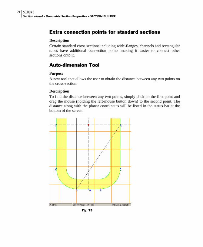
SECTION 3 Section.wizard - Geometric Section Properties – SECTION BUILDER
72
Extra connection points for standard sections
Description Certain standard cross sections including wide-flanges, channels and rectangular tubes have additional connection points making it easier to connect other sections onto it.
Auto-dimension Tool
Purpose A new tool that allows the user to obtain the distance between any two points on the cross-section.
Description To find the distance between any two points, simply click on the first point and drag the mouse (holding the left-mouse button down) to the second point. The distance along with the planar coordinates will be listed in the status bar at the bottom of the screen.
Fig. 75

SECTION 3 SECTION BUILDER - Geometric Section Properties - Section.wizard
73
Error in calculating plastic section modulus for Tee sections
Description
The calculation of the plastic section modulii along both major and minor axes was incorrect for ASTM American Standard, Miscellaneous and Wide-Flange Tees. This has been fixed which is reflected by the distribution of a new USA.PRF file.

SECTION 3 Section.wizard - Geometric Section Properties – SECTION BUILDER
74

Sezam – Selection of Equivalent Sections An arbitrary section, at best, can be checked for strength according to the formulas given in the manual on strength of materials. But when the question is about the elastoplastic stage, flat form bending stability, buckling from the power plane or other checks by norms, all the standardizing documents are directed toward only certain cross-sections. Usually engineers take the following approach – the strength is checked for the actual cross-section and all the other checks are carried out for a “similar” section, the geometric properties of which are selected according to the consideration of equivalence.
Fig. 76 Sezam window
The equivalence is understood in the sense of the cross-section geometric properties, area, moments of inertia, resisting moments, etc. Sometimes, in the process of reduction, some additional considerations are used which aid in the conception of equivalence. For example, it is achieved only the equation of inertia moments, if the stability checking has to be done only.
The Sezam program is used to find an equivalent cross-section, which approximates the user-defined section according to its geometric properties. The current version of Sections.wizard only allows you to find equivalent sections as box, I-beam or channel. An initial section can be set:
as a file received from the results of the Section Builder program as a file received from the result of the Freesketch program

SECTION 4 Section.wizard - Geometric Section Properties – SEZAM
76
by entering geometric properties as a built-up section from the set of prototypes given in the program
(e.g. two channels, two I-beams, …) Only geometrical properties are used for the calculation in the program. The following properties are approximated for a section:
area (A) principal moments of inertia (Iu,Iv) resisting moments (Wu+, Wu-, Wv+, Wv-)
Apart from the parameters mentioned above, it is necessary to set weight coefficients for each of the properties. All the weights are equal to 1 by default.
The task is to select geometric dimensions of a box, channel or I-beam by minimizing the following function.
where A0, Iu0, Iv
0, W0u+, W0
u-, W0v+, W0
v- are the corresponding geometric properties of the selected section (a box, channel or I-beam).
Coefficients ki (i=1…7) are weight (importance) factors. It is possible to abandon approximation of a geometric property by setting the corresponding coefficient equal to zero.
Selection Results
Upon clicking the Find button, the program finds an equivalent section in accordance with the selected prototype (an I-beam, an equal I-beam, a box, a rectangular hollow section or a channel) and with the selected weight coefficients. The selected section and its dimensions are shown in the window (Fig.77). The geometric properties of the equivalent section and the divergences of initial and resultant section values for each of geometric propertied are represented simultaneously.
,)1()1(
)1()1()1()1()1(
207
206
205
204
203
202
201
−
−
+
+
−
−
+
+
−+−
+−+−+−+−+−
v
v
v
v
u
u
u
u
v
v
u
u
WWk
WWk
WWk
WWk
IIk
IIk
AAk
(1)

SECTION 4 SEZAM - Geometric Section Properties - Section.wizard
77
Fig. 77 The Sections dialog box with selection results
If the initial section selected is a file created by the Freesketch or Section Builder program, the initial and equivalent sections are simultaneously represented in the window (Fig. 78).
Fig. 78 The Sections dialog box with selection results (window shows the initial and equivalent sections)
Run Section Builder The Run Section Builder icon activates Section Builder and opens the selected equivalent section automatically. With Section Builder a user is able to calculate additional geometric properties and modify the section.
Run Freesketch The Run Freesketch icon activates Freesketch and opens the selected equivalent section automatically. With Freesketch a user is able to calculate additional geometric properties and modify the section.

SECTION 4 Section.wizard - Geometric Section Properties – SEZAM
78

Appendixes
Definitions of Geometric Properties
Moments of Inertia
Calculations for some geometric properties (e.g. area, moment of inertia, center of gravity) are based on the calculation of moments of the (Ω) zone covered by a section, i.e. the calculation of values of the form
∫Ω
=ν zdydzy qppq .
E.g. when p = q = 0 we get the section area A.
Often the calculation of moments normalized by the area (A) is required, i.e. values of the form
αpq = νpq/A. At that, values α01 and α10 determine the section gravity center.
When p+q ≥ 2 the central moments are of interest.
∫Ω
α−α−=µ zdydzy qppq )()( 0110
Values µ20, µ02, µ11 are the central moments of inertia about axes Z, Y and the centrifugal moment of inertia correspondingly.
Principal Moments of Inertia, Angle of Principal Axes
22
22 yzzyzy
vu I
IIIII +⎟⎟
⎠
⎞⎜⎜⎝
⎛ −±
+=
)(.
Angle of the principal axes of inertia

SECTION 5 Section.wizard - Geometric Section Properties – APPENDIXES
80
⎟⎟⎟⎟
⎠
⎞
⎜⎜⎜⎜
⎝
⎛
−=α
vuy
yz
III
tana .
In the last formula for determining the axis angle of the greatest moment of inertia, Iu is to be put to the right side; for determining the axis angle of the least moment of inertia Iv is to be put on the right side.
Remark: Freesketch allows working with zones limited not only by polygons, but by curves as well. This occurs when the Smooth Angle and Create Round Hole functions are used. In this case, the program substitutes a curve for a polyline while calculating.
Radii of Inertia
AI
i yy = ;
AI
i zz = ;
AI
i uu = ;
AI
i vv = .
Resisting Moments
Axial resisting moments:
maxvI
W uu =+ ;
minvI
W uu =− ;

SECTION 5 APPENDIXES - Geometric Section Properties -
81
maxuI
W vv =+ ;
minuI
W vv =− ,
where umax,umin,vmax,vmin are correspondingly maximum distances from a section exterior boundary to the axes U, V (on one and another side).
Polar resisting moment:
,maxρ
+=ρ
zy IIW
where ρmax is the maximum distance from section points to the center of gravity.
The value Iy+Iz is the polar moment of inertia.
Radius of Gyration
AW
a uu
++ = ;
AW
a uu
−− = ;
AW
a vv
++ = ;
AW
a vv
−− = .
Torsional Rigidity
Let us examine the function ϕ(y, z) in the Ω zone (function of stresses or Prandtl function), which satisfy an equation
∆ϕ + 2 = 0

SECTION 5 Section.wizard - Geometric Section Properties – APPENDIXES
82
and, besides, ϕ = 0 on the boundary of the Ω zone in the case when Ω does not contain holes. In the case of a boundary containing holes, it is assumed that ϕ = 0 on the exterior boundary of the Ω zone, but the stress function is constant on each of the interior boundaries (Li, i=1…n), at that, the constants Ui (i=1…n) are such that the relationships are accomplished
,dsn i
Li
Ω−=∂ϕ∂
∫ 2
where ΩI is the area of zone limited by the contour Li.
The value ∑∫=Ω
Ω+ϕ=n
iiit )Udydz)z,y((I
1
2 is named the torsional moment of
inertia.
Shear Center
Shear center coordinates (in the principal central axes) are determined according to the formulas
∫Ω
ω= zdydz)z,y(J
yy
1 ;
∫Ω
ω−= ,ydydz)z,y(J
zz
1
where ω(y, z) is the Saint-Venant torsion function or the function of displacements. This function is harmonious for the Ω (∆ω = 0) zone and on the boundary it satisfies the condition
nzcosynycoszn
−=∂ω∂
and, furthermore
0dsn
=∂ω∂
∫ .

SECTION 5 APPENDIXES - Geometric Section Properties -
83
Section Areas at Shear
Let us assume that there is a section where the axes Y, Z are principal
Fig. A1
Let
∫=tz
z
dn)n(nb)z(Q .
The shearing area about Y-axis is the following value
∫t
b
z
z
y
dz)z(b)z(Q
I2
2
.
The shearing area about Z-axis is determined similarly.

SECTION 5 Section.wizard - Geometric Section Properties – APPENDIXES
84
Plastic Resisting Moments
Let us mark a section zone as Ω. Let Ω2 be a part of the Ω zone located on one side of the principal U-axis. The section plastic resisting moment at flexure about U-axis is
∫Ω
ω=2
vd2W u,pl .
The plastic moment Wpl,v about the principal V-axis is determined similarly.
Sectorial Properties
The section inertia bimoment (sectorial moment) for massive sections
∫Ω
ω ω= ,dydz)z,y(I 2
where ω(y,z) is the Saint-Venant torsion function.
Sectorial static moment:
∫Ω
ω ω= dydz)z,y(S .
It should be noted that the sectorial characteristics are usually used in the theory of thin-walled rods by V.Z.Vlasov1. But, as G.Y.Djanelidze2 proved, the above mentioned formulas are applicable to sections of any shape and with the 1+О(h/ρ) accuracy correspond to the conception of bimoment and sectorial static moment of Vlasov theory, where h is the thickness of thin-walled section, ρ is a curvature radius.
1V.Z.Vlasov, Thin-Walled Elastic Beams, Israel Program for Scientific Translations, Jerusalem, 1961 2 G.Yu.Djanelidze To the theory of thin-wall bars Appl. Math. and Mech. 1949, XIII, No 6, 597-.608

SECTION 5 APPENDIXES - Geometric Section Properties -
85
Normal Stress
The components of strain in a section are to be set, i.e. the component N of the force vector and the components Mu, Mv of the integral moment about section gravity.
The value of normal stress at a point is
v
v
u
u
IuM
IvM
AN ⋅
−⋅
−=σ ,
where vu M,M,N correspondingly are a normal force and moments (in the principal axes) acting in a section; u,v are the coordinates of a point in the section principal axes.
File Format Section.wizard can import sections created by other programs. In particular, Freesketch is able to import files of the CON type (created, for example, by the SCAD program).
CON files are the files of the following structure:
The section is described by a set of polygons The first polygon is the external contour, and all the following (if
applicable) describe holes (internal contours) Each polygon (external or internal) is described as follows:
The first line is the whole number n, which determines the number of polygon vertices
n lines follow, each line contains three digits with the floating point, which are the coordinates of the next point in the section plane and the radius of a contour curvature at this point. The last number can be absent, assumed that the curvature is absent.
All the dimensions are set in meters. The separator between two numbers is a space. A “.” Following a number denotes a decimal point
Example: The section shown below is described in the CON format as follows:

SECTION 5 Section.wizard - Geometric Section Properties – APPENDIXES
86
Fig. A2
12
-1.000 3.000
3.0. 0.000
3.1. -1.000
3.2. -1.000
3.3. 0.000
3.4. 3.000
3.5. 6.000
3.6. 9.000
3.7. 10.000
3.8. 10.000
3.9. 9.000 -1.000 6.000
4
3.0. 3.000
3.1. 3.000
3.2. 6.000 3.000 6.000

SECTION 5 APPENDIXES - Geometric Section Properties -
87
Adding Parametric Sections A qualified user can extend the parametric sections set by adding his own prototypes.
To do this, the following is required:
change the ParamSec.ini prepare two drawings in the BMP format (Windows Bitmap) prepare the DSC type file with the description of a new parametric section
The ParamSec.ini file contains the list of parametric sections and has the format:
[LIST]
quantity=n — <quantity of types of parametric sections >
…….
Name<i>1=<file name with the i-type description >
………
Example:
[LIST]
quantity=10
Name1=RoundRect.dsc
Name2=Hollow.dsc
Name3=Channel.DSC
Name4=CP.DSC
Name5=I.DSC
Name6=T.DSC
Name7=TT.DSC
Name8=Wedge.DSC
Name9=Z.DSC
Name10=Pipe.DSC

SECTION 5 Section.wizard - Geometric Section Properties – APPENDIXES
88
Files with descriptions of parametric sections have the DSC extension and are text files of the following structure:
Each line, beginning with symbols // is considered a comment line and does not keep “useful” information. Henceforward, when speaking about the I-line we mean the number of a line without comment lines.
The first line contains the BMP file of a small section drawing, which appears in the list of parametric sections type. The recommended size of the drawing is 64x32 pixels.
The second line contains the BMP file of a section drawing with parameter dimensions. The recommended size of this drawing is 140x148.
The third line is the number of parameters, n There are n lines with the description of parameters. Each line contains
three fields separated by spaces. 1 The digit 0 or 1. 0 if a parameter is able to possess a zero value or 1
otherwise). It is assumed that all the parameters are able to possess nonnegative values only.
2 The digit 0 if a parameter is a linear dimension and 1 for angular dimensions.
3 A parameter name up to 4 characters in length. On the next line the number of restrictions, m, for the relations between the parameters is to be given, followed by m lines with the description of restrictions. The restrictions are to be represented in the form of inequality of the type X ≤ Y. Each line with the restriction consists of three fields separated by semicolons (;).
1 Inequality upper boundary 2 Inequality lower boundary 3 Information text at the disturbance of the given restriction. The
information is displayed as “Disturbance of restriction”: <text>. Upper and lower boundaries can be entered in the form of formulae. Parameters are given as variables in these formulae. Parameters must be lower case letters of the latin alphabet. The following rules apply to parameter names:
a — parameter 1
b — parameter 2

SECTION 5 APPENDIXES - Geometric Section Properties -
89
Formulae can contain:
arithmetic operations using symbols +, -, *, /, exponentiation ^ (e.g. 2.5*2.5*2.5 is entered as 2.5^3)
parentheses elemental functions.
The following functions can be used in formulae:
floor – the greatest whole number not exceeding the given one tan – tangent
sin – sine
cos – cosine
asin – antisine
acos – anticosine
atan – antitangent
exp – exponent
ceil – the least whole number exceeding the given one
tanh – hyperbolic tangent
sinh – hyperbolic sine
cosh – hyperbolic cosine
log – natural logarithm
log10 – common logarithm
abs – absolute value
sqrt – square root Arguments of trigonometric functions (sin, cos, tan) and results of arc trigonometric functions (asin, acos, atan) are set up/obtained in degrees.
Only parentheses should be used at arbitrary embedding depth.
Last, section contour data is formatted similar to the CON file format. However, instead of three digits (two coordinates and a rounding-off radius), formulae for calculation of these coordinates and a radius depending on parameters are to be used. Formulae are to be ended with the “semicolon” symbol (;).

SECTION 5 Section.wizard - Geometric Section Properties – APPENDIXES
90
Example 1:
Drawing RoundRectS.bmp
Drawing RoundRectL.bmp
// rounded rectangle
// images (small and large)
RoundRectS.bmp
RoundRectL.bmp
// quantity, unit types, and names of
//parameters
3
1 0 a
1 0 b
0 0 r
// verification
2
c;a/2; r<=a/2
c;b/2; r<=b/2
// nodes (quantity; 2 coordinates and
//radius)
4
-a/2;-b/2;c
-a/2;b/2;c
a/2;b/2;c
a/2;-b/2;c

SECTION 5 APPENDIXES - Geometric Section Properties -
91
Example 2:
Drawing CPS.bmp
Drawing CPL.bmp
// images (small and large) CPS.bmp CPL.bmp // quantity, unit types, and names of //parameters 6 1 0 a 1 0 b 1 0 c 1 0 d 1 0 e 1 0 f // verification — quantity of inequalities 2 f+c;b; f+c < b 2*(e+d);a; 2(e+d) < a // nodes (quantity; 2 coordinates and radius) 8 0;0;0 0; b-c;0 -e;b-c;0 -e;b;0 a-e;b;0 a-e;b-c;0 a-2*e;b-c;0 a-2*e;0;0 4 d;f;0 d;b-c;0 a-2*e-d;b-c;0 a-2*e-d;f;0
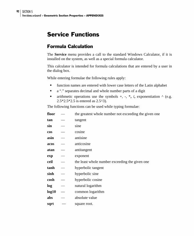
SECTION 5 Section.wizard - Geometric Section Properties – APPENDIXES
92
Service Functions
Formula Calculation
The Service menu provides a call to the standard Windows Calculator, if it is installed on the system, as well as a special formula calculator.
This calculator is intended for formula calculations that are entered by a user in the dialog box.
While entering formulae the following rules apply: function names are entered with lower case letters of the Latin alphabet a “.” separates decimal and whole number parts of a digit arithmetic operations use the symbols +, -, *, /, exponentiation ^ (e.g.
2.5*2.5*2.5 is entered as 2.5^3). The following functions can be used while typing formulae:
floor — the greatest whole number not exceeding the given one tan — tangent sin — sine cos — cosine asin — antisine acos — anticosine atan — antitangent exp — exponent ceil — the least whole number exceeding the given one tanh — hyperbolic tangent sinh — hyperbolic sine cosh — hyperbolic cosine log — natural logarithm log10 — common logarithm abs — absolute value sqrt — square root.

SECTION 5 APPENDIXES - Geometric Section Properties -
93
Depending on the radio button position, Degrees/Radians, arguments of trigonometric functions (sin, cos, tan) and the results of arc trigonometric functions (asin, acos, atan) are given in degrees or radians correspondingly.
Only parentheses should be used at arbitrary embedding depth.
Fig. A3 Formula Calculation window
Example:
The formula
5 003.08.67.6)43.0sin(2.1 −++ is to be entered as:
1.2+sin(0.43)+6.7*sqrt(6.8)-0.003^0.2 . Once the Variables button is pressed, there is an option to use three independent variables x, y, z in the formula. At that, the values of variables are set up in the corresponding window boxes. This allows carrying out a series of uniform calculations at different parameter values. For example, the formula
58.67.6)sin(2.1 yx −++ is to be entered as
1.2+sin(x)+6.7*sqrt(6.8)-y^0.2 For calculations, the Calculation button is to be pressed. The Copy button allows sending results to the exchange buffer.
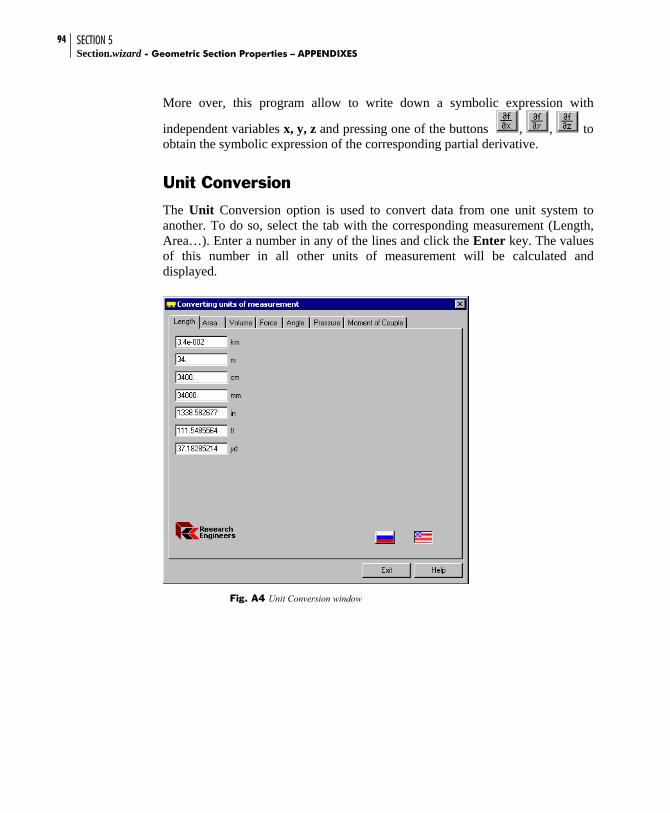
SECTION 5 Section.wizard - Geometric Section Properties – APPENDIXES
94
More over, this program allow to write down a symbolic expression with
independent variables x, y, z and pressing one of the buttons , , to obtain the symbolic expression of the corresponding partial derivative.
Unit Conversion
The Unit Conversion option is used to convert data from one unit system to another. To do so, select the tab with the corresponding measurement (Length, Area…). Enter a number in any of the lines and click the Enter key. The values of this number in all other units of measurement will be calculated and displayed.
Fig. A4 Unit Conversion window

SECTION 5 APPENDIXES - Geometric Section Properties -
95
Program Interface Files created by Section Builder (the SEC file) and Freesketch (the CNS file) can be used in other programs, e.g. in programs for the analysis of stressed-deformed state of buildings and constructions to specify rigid properties for rod elements. For this purpose one can use the dynamically loaded libraries supplied with Section.wizard.
Using Section Builder Files
An application using the Section Builder file should load this file to the operative memory. Then the application can use two functions from the SD.DLL dynamically loaded library:
1. Drawing a section
void SDDraw(HDC hDC, // context of representation device
LPRECT Rect, // cursor to a rectangle of drawing
void *Buffer);// cursor to the information buffer
// loaded from the SEC file 2. Calculation of geometric properties
void SDCalc(void *Buffer,// cursor to the information buffer
loaded from the SEC file
struct GeoProperties *GeoProp); // cursor to the
//structure with calculated
//geometric properties (see below)
struct GeoProperties
double A; // sectional area
double Avy; // reserve
double Avz; // reserve

SECTION 5 Section.wizard - Geometric Section Properties – APPENDIXES
96
double alpha; // Angle of principal inertia axes
double Iy; // Inertia moment about central axis Y1 // parallel to Y-axis
double Iz; // Inertia moment about central axis Z1 // parallel to Z-axis
double It; // Torsional moment of inertia
double Iw; // reserve
double iy; // Radius of inertia about Y1-axis
double iz; // Radius of inertia about Z1-axis
double Ys; // reserve
double Zs; // reserve
double Wyplus; // Maximum resisting moment about U-axis
double Wyminus; // Minimum resisting moment about U-axis
double Wzplus; // Maximum resisting moment about V-axis
double Wzminus; // Minimum resisting moment about V-axis
double Wply; // Plastic resisting moment about U-axis
double Wplz; // Plastic resisting moment about V-axis
double Iu; // Maximum inertia moment
double Iv; // Minimum inertia moment double
iu; // Maximum radius of inertia
double iv; // Minimum radius of inertia double ayplus; // nucleus distances double ayminus;
double azplus;

SECTION 5 APPENDIXES - Geometric Section Properties -
97
double azminus;
double xM; // y-coordinate of gravity center
double yM; // z-coordinate of gravity center double Iyz; // reserve
;
Using Freesketch Program Files
An application using the Freesketch file should load the file (with the CNS extension) to the operative memory. The first six bytes of the file contain the “Freesketch” signature, which can be used for controlling the right and check-up of the fact that the file was created by Freesketch. Then the application can use two functions realized in the dynamically launched libraries ModelDLL.DLL and CalcDLL.DLL:
1. Drawing a section
BOOL ConDraw(
const char* buf, // cursor to information buffer loaded from CNS file
// with 11 bytes bias int size, // CNS file size decreased
for 11 bytes
HDC hDC, // context of representation device
const RECT * Rect); // cursor to a rectangle of drawing
2. Calculation of geometric properties
void ConCalc (
const char* buf, // cursor to information buffer launched from
// CNS file with 11 bytes bias int size, // CNS file size decreased for 11
bytes

SECTION 5 Section.wizard - Geometric Section Properties – APPENDIXES
98
double Mu, // Puasson coefficient
struct GeoPropertiesEx *geo, // cursor to a structure with calculated
// geometrical properties (see below)
BOOL Full); // calculation criterion of all the geometric properties (Full = TRUE) or
// only inertia moment and the center of gravity (Full=FALSE)
struct GeoPropertiesEx
double A; // sectional area
double Avy; // reserve
double Avz; // reserve
double alpha; // Angle of principal inertia axes
double Iy; // Inertia moment about central axis Y1 parallel to Y-axis
double Iz; // Inertia moment about central axis Z1 parallel to Z-axis
double It; // Torsional moment of inertia
double Iw; // reserve
double iy; // Radius of inertia about Y1-axis
double iz; // Radius of inertia about Z1-axis
double Ys; // reserve
double Zs; // reserve
double Wyplus; // Maximum resisting moment about U-axis
double Wyminus; // Minimum resisting moment about U-axis
double Wzplus; // Maximum resisting moment about V-axis
double Wzminus; // Minimum resisting moment about V-axis
double Wply; // Plastic resisting moment about U-axis
double Wplz; // Plastic resisting moment about V-axis
double Iu; // Maximum inertia moment
double Iv; // Minimum inertia momrnt
double iu; // Maximum radius of inertia

SECTION 5 APPENDIXES - Geometric Section Properties -
99
double iv; // Minimum radius of inertia
double ayplus; // nucleus distances
double ayminus;
double azplus;
double azminus;
double xM; // y—coordinate of gravity center
double yM; // z—coordinate of gravity center
double Iyz; // reserve
double Sw; // sectorial static moment
double Yb; // y—coordinate of flexural center
double Zb; // z—coordinate of flexural center
double P; // Perimeter
double Pi; // internal perimeter
double Pe; // external perimeter
double I1; // Inertia moment in global system of coordinates about Y-axis
double I2; // Inertia moment in global system of coordinate about Z-axis
double I12; // Centrifugal inertia moment in global system of coordinate
double Ip; // Polar inertia moment
double ip; // Polar radius of inertia
double Wp; // Polar resisting radius
;

SECTION 5 Section.wizard - Geometric Section Properties – APPENDIXES
100
Exporting Data Section geometric properties export to the SCAD calculating complex by loading data from the SEC and CNS files in the regime of rigid properties setting to rod elements. It is also possible to export data to STAAD-III and STAAD.Pro.
Section Builder and Freesketch
To export data from Section Builder and Freesketch, use the Export to STAAD operation in the File menu and to select a type according to which the data will be exported (General or Prismatic). In the Open User’s Table dialog box, specify a directory and a table name where section parameters are to be entered. The table type should correspond to the section type. If the table with the specified name does not exist, a new table is created. After selecting the table name and clicking the Open button, the General dialog box appears for the General type of data or Prismatic for the Prismatic type.
Fig. A5 General dialog box
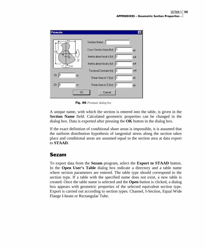
SECTION 5 APPENDIXES - Geometric Section Properties -
101
Fig. A6 Prismatic dialog box
A unique name, with which the section is entered into the table, is given in the Section Name field. Calculated geometric properties can be changed in the dialog box. Data is exported after pressing the OK button in the dialog box.
If the exact definition of conditional share areas is impossible, it is assumed that the uniform distribution hypothesis of tangential stress along the section takes place and conditional areas are assumed equal to the section area at data export to STAAD.
Sezam
To export data from the Sezam program, select the Export to STAAD button. In the Open User’s Table dialog box indicate a directory and a table name where section parameters are entered. The table type should correspond to the section type. If a table with the specified name does not exist, a new table is created. Once the table name is selected and the Open button is clicked, a dialog box appears with geometric properties of the selected equivalent section type. Export is carried out according to section types: Channel, I-Section, Equal Wide Flange I-beam or Rectangular Tube.

SECTION 5 Section.wizard - Geometric Section Properties – APPENDIXES
102
Fig. A7 Equal Wide Flange I-beam dialog box
Fig. A8 Channel dialog box

SECTION 5 APPENDIXES - Geometric Section Properties -
103
Fig. A9 Rectangular Tube dialog box
Fig. A10 I-Section dialog box
For a section of the Box type, it is required to select a type in accordance with which the data will be exported (General or Prismatic). Dialog boxes with section properties of these types are described above in the description of data export from the Section Builder and Freesketch programs.

SECTION 5 Section.wizard - Geometric Section Properties – APPENDIXES
104
A unique name, with which the section is entered into the table, is given in the Section Name field. Calculated geometric properties can be changed in the dialog box. Data is exported after pressing the OK button in the dialog box.
If the exact definition of conditional share areas is impossible, it is assumed that the uniform distribution hypothesis of tangential stress along the section takes place and conditional areas are assumed equal to the section area at data export to STAAD.
Add selection of measure units for the export to STAAD
Purpose
Exporting the section properties obtained from Sectionwizard can now be exported to a user-defined STAAD.Pro table in any unit system.
Description
After creating and analyzing a cross-section, go to File->Export to STAAD-III and choose either General or Prismatic section. After providing a table name, the following dialog box will popup prompting for the proper unit system for the property values to be exported to.
Figure 79

SECTION 5 APPENDIXES - Geometric Section Properties -
105
List of Metal-Rolled Profile Assortments Supplied with Structure.Wizard
Assortment of Cheliabinsk Steel Plant (Cheliabinsk Metal Manufacturers)
Regular I-beam per STO ASChM 20-93
Broad-flanged beam per STO ASChM 20-93
Column I-beam per STO ASChM 20-93
I-beam R 40-93
Special I-beam per STO ASChM 20-93
GOST
Equal legs angle per GOST 8509-93
Unequal legs angle per GOST 8510-86*
Channel with parallel edges of flanges per GOST 8240-89
Channel per GOST 8240-89
Channel with inclined inner edges of flanges per GOST 8240-89
Column I-beam GOST 26020-83
I-beam with inclined inner edges of flanges per GOST 8239-89
Additional series I-beam GOST 26020-83
Regular I-beam per GOST 26020-83
Broad-flanged beam per GOST 26020-83
Column T-bar per TU 14-2-685-86
T-bar per TU 14-2-685-86
Pipe per GOST 10704-91
Pipe per GOST 10704-91 ( reduced list )
Channel with inclined inner edges of flanges per GOST 8240-89
Channel with inclined inner edges of flanges per GOST 8240-89
Square Hollow Structural Tubing per TU 36-2287-80
Rectangular Hollow Structural Tubing per TU 67-2287-80

SECTION 5 Section.wizard - Geometric Section Properties – APPENDIXES
106
Reduced GOST Assortment
Equal legs angle per GOST 8509-93
Unequal legs angle per GOST 8510-86*
Channel with parallel edges of flanges per GOST 8240-89
Channel with inclined inner edges of flanges per GOST 8240-89
Column I-beam GOST 26020-83
I-beam with inclined inner edges of flanges per GOST 8239-89
Additional series I-beam GOST 26020-83
Regular I-beam per GOST 26020-83
Broad-flanged beam per GOST 26020-83
Column T-bar per TU 14-2-685-86
T-bar per TU 14-2-685-86
Pipe per GOST 10704-91
Channel with inclined inner edges of flanges per GOST 8240-89
Channel with inclined inner edges of flanges per GOST 8240-89
Square Hollow Structural Tubing per TU 36-2287-80
Rectangular Hollow Structural Tubing per TU 67-2287-80
Old Assortments
Equal legs angle per OST 14-1926
Equal legs angle per OST 14-1932
Unequal legs angle per OST 15-1926
Unequal legs angle per OST 15-1932
I-beam per OST 16-1926
I-beam per OST 16-1932
Channel with inclined inner edges of flanges per OST 17-1926
Channel with inclined inner edges of flanges per OST 17-1933

SECTION 5 APPENDIXES - Geometric Section Properties -
107
ASTM
Equal Angles
Unequal Angles
H-Piles
Miscellaneous Shapes
American Standard Shapes
Wide Flange Shapes
Miscellaneous Tees
American Standard Tees
Wide Flange Tees
American Standard Channels
Miscellaneous Channels
Pipe
Extra Strong Pipe
Double-Extra Strong Pipe
Tube Steel (Square)
Tube Steel (Rectangular)
British Steel Sections
Channels
Structural Tees cut from UB's
Structural Tees cut from UC's
British Standard Sections
Universal Beams
Universal Columns
Universal Bearing Piles
Rectangular Hollow Sections
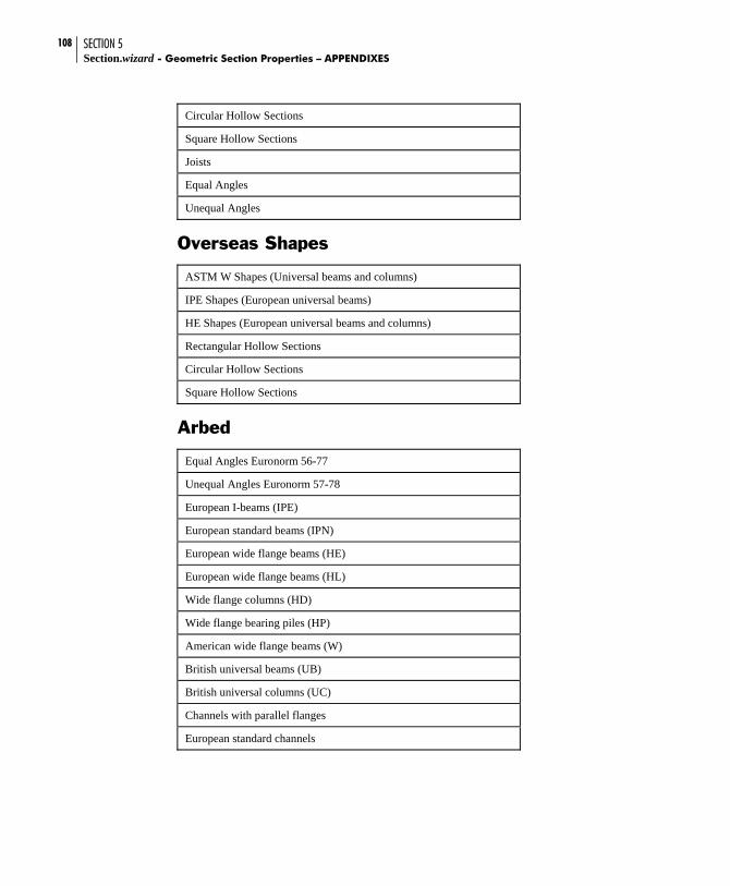
SECTION 5 Section.wizard - Geometric Section Properties – APPENDIXES
108
Circular Hollow Sections
Square Hollow Sections
Joists
Equal Angles
Unequal Angles
Overseas Shapes
ASTM W Shapes (Universal beams and columns)
IPE Shapes (European universal beams)
HE Shapes (European universal beams and columns)
Rectangular Hollow Sections
Circular Hollow Sections
Square Hollow Sections
Arbed
Equal Angles Euronorm 56-77
Unequal Angles Euronorm 57-78
European I-beams (IPE)
European standard beams (IPN)
European wide flange beams (HE)
European wide flange beams (HL)
Wide flange columns (HD)
Wide flange bearing piles (HP)
American wide flange beams (W)
British universal beams (UB)
British universal columns (UC)
Channels with parallel flanges
European standard channels

SECTION 5 APPENDIXES - Geometric Section Properties -
109
OTUA
Equal Angles NF A 45-009
Unequal Angles NF A 45-010
IPN Shapes NF A 45-209
PA Shapes NF A 45-205
IPE-A Shapes NF A 45-205
IPE Shapes NF A 45-205
IPE-R Shapes NF A 45-205
HEA-A Shapes NF A 45-201
HEA Shapes NF A 45-201
HEB Shapes NF A 45-201
HEM, HEC Shapes NF A 45-201
Structural Tees cut from PA NF A 45-205
Structural Tees cut from IPE-A NF A 45-205
Structural Tees cut from IPE NF A 45-205
Structural Tees cut from IPE-R NF A 45-205
Structural Tees cut from HEA-A NF A 45-211
Structural Tees cut from HEA NF A 45-201
Structural Tees cut from HEB NF A 45-201
Structural Tees cut from HEM, HEC NF A 45-201
Channels UPN NF A 45-202
Channels UPN-A NF A 45-202
Channels UAP NF A 45-255
Channels UAP-A NF A 45-255
Tubes Ronds
Tubes Rectangular
Tubes Carres

SECTION 5 Section.wizard - Geometric Section Properties – APPENDIXES
110
DIN
Equal Angles DIN 1028
Unequal Angles DIN 1029
Beam DIN 1025
IP DIN 1025
IP DIN 1025 (9%)
Channels DIN 1026
Circular Hollow Sections DIN 2448
Rectangular Hollow Sections DIN 59410
Square Hollow Sections DIN 59410