· basic electrical engineering for b.e./b.tech. and other engineering examinations v.k. mehta...
TRANSCRIPT

www.EngineeringBooksPdf.com

BASIC ELECTRICAL ENGINEERING
For B.E./B.Tech. and Other Engineering Examinations
V.K. MEHTAROHIT MEHTA
S. CHAND & COMPANY PVT. LTD.(AN ISO 9001 : 2008 COMPANY)
RAM NAGAR, NEW DELHI – 110 055
www.EngineeringBooksPdf.com

S. CHAND & COMPANY LTD.(An ISO 9001 : 2008 Company)Head Office: 7361, RAM NAGAR, NEW DELHI - 110 055Phone: 23672080-81-82, 9899107446, 9911310888 Fax: 91-11-23677446Shop at: schandgroup.com; e-mail: [email protected]
Branches :AHMEDABAD : 1st Floor, Heritage, Near Gujarat Vidhyapeeth, Ashram Road, Ahmedabad - 380 014,
Ph: 27541965, 27542369, [email protected] : No. 6, Ahuja Chambers, 1st Cross, Kumara Krupa Road, Bengaluru - 560 001,
Ph: 22268048, 22354008, [email protected] : Bajaj Tower, Plot No. 243, Lala Lajpat Rai Colony, Raisen Road, Bhopal - 462 011,
Ph: 4274723. [email protected] : S.C.O. 2419-20, First Floor, Sector - 22-C (Near Aroma Hotel), Chandigarh -160 022,
Ph: 2725443, 2725446, [email protected] : 152, Anna Salai, Chennai - 600 002, Ph: 28460026, 28460027, [email protected] COIMBATORE : No. 5, 30 Feet Road, Krishnasamy Nagar, Ramanathapuram, Coimbatore -641045,
Ph: 0422-2323620 [email protected] (Marketing Office)CUTTACK : 1st Floor, Bhartia Tower, Badambadi, Cuttack - 753 009, Ph: 2332580; 2332581,
[email protected] : 1st Floor, 20, New Road, Near Dwarka Store, Dehradun - 248 001, Ph: 2711101, 2710861,
[email protected] : Pan Bazar, Guwahati - 781 001, Ph: 2738811, 2735640 [email protected] : Padma Plaza, H.No. 3-4-630, Opp. Ratna College, Narayanaguda, Hyderabad - 500 029,
Ph: 24651135, 24744815, [email protected] : 1st Floor, Nand Plaza, Hawa Sadak, Ajmer Road, Jaipur - 302 006,
Ph: 2219175, 2219176, [email protected] : Mai Hiran Gate, Jalandhar - 144 008, Ph: 2401630, 5000630, [email protected] : 67/B, B-Block, Gandhi Nagar, Jammu - 180 004, (M) 09878651464 (Marketing Office)KOCHI : Kachapilly Square, Mullassery Canal Road, Ernakulam, Kochi - 682 011, Ph: 2378207, co-
[email protected] : 285/J, Bipin Bihari Ganguli Street, Kolkata - 700 012, Ph: 22367459, 22373914,
[email protected] : Mahabeer Market, 25 Gwynne Road, Aminabad, Lucknow - 226 018, Ph: 2626801, 2284815,
[email protected] : Blackie House, 103/5, Walchand Hirachand Marg, Opp. G.P.O., Mumbai - 400 001,
Ph: 22690881, 22610885, [email protected] : Karnal Bag, Model Mill Chowk, Umrer Road, Nagpur - 440 032, Ph: 2723901, 2777666
[email protected] : 104, Citicentre Ashok, Govind Mitra Road, Patna - 800 004, Ph: 2300489, 2302100,
[email protected] : 291/1, Ganesh Gayatri Complex, 1st Floor, Somwarpeth, Near Jain Mandir,
Pune - 411 011, Ph: 64017298, [email protected] (Marketing Office)RAIPUR : Kailash Residency, Plot No. 4B, Bottle House Road, Shankar Nagar, Raipur - 492 007,
Ph: 09981200834, [email protected] (Marketing Office)RANCHI : Flat No. 104, Sri Draupadi Smriti Apartments, East of Jaipal Singh Stadium, Neel Ratan Street,
Upper Bazar, Ranchi - 834 001, Ph: 2208761, [email protected] (Marketing Office)
SILIGURI : 122, Raja Ram Mohan Roy Road, East Vivekanandapally, P.O., Siliguri-734001, Dist., Jalpaiguri, (W.B.) Ph. 0353-2520750 (Marketing Office)
VISAKHAPATNAM : Plot No. 7, 1st Floor, Allipuram Extension, Opp. Radhakrishna Towers, Seethammadhara North Extn., Visakhapatnam - 530 013, (M) 09347580841, [email protected] (Marketing Office)
© 1988, V.K. Mehta and Rohit Mehta All rights reserved. No part of this publication may be reproduced or copied in any material form (including photo copying or storing it in any medium in form of graphics, electronic or mechanical means and whether or not transient or incidental to some other use of this publication) without written permission of the copyright owner. Any breach of this will entail legal action and prosecution without further notice.Jurisdiction : All disputes with respect to this publication shall be subject to the jurisdiction of the Courts, tribunals and forums of New Delhi, India only.
First Edition 1988; Subsequent Editions and Reprints 1991, 95, 97, 98, 2001, 2006, 2007, 2008 (Thrice), 2009 (Twice), 2010 (Twice); 2011; Revised Edition 2012
Code : 10A 113 ISBN : 81-219-0871-X
www.EngineeringBooksPdf.com

Preface to Sixth Edition
The general response to the Fifth Edition of the book was very encouraging. Authors feel that their work has been amply rewarded and wish to express their deep sense of gratitude to the large number of readers who have used it and in particular to those of them who have sent helpful sugges-tions from time to time for the improvement of the book.
The popularity of the book is judged from the fact that authors frequently receive feedback from many quarters including teachers, students and serving engineers. This feedback helps the authors to make the book up-to-date. In the present edition, many new topics/numericals/illustrations have been added to make the book more useful.
Authors lay no claim to the original research in preparing the book. Liberal use of materials available in the works of eminent authors has been made. What they may claim, in all modesty, is that they have tried to fashion the vast amount of material available from primary and secondary sources into coherent body of description and analysis.
The authors wish to thank their colleagues and friends who have contributed many valuable suggestions regarding the scope and content sequence of the book. Authors are also indebted to S. Chand & Company Ltd., New Delhi for bringing out this revised edition in a short time and pricing the book moderately inspite of heavy cost of paper and printing.
Errors might have crept in despite utmost care to avoid them. Authors shall be grateful if these are pointed out along with other suggestions for the improvement of the book.
V.K. MEHTA
ROHIT MEHTA
Disclaimer : While the authors of this book have made every effort to avoid any mistake or omission and have used their skill, expertise and knowledge to the best of their capacity to provide accurate and updated information. The authors and S. Chand does not give any representation or warranty with respect to the accuracy or completeness of the contents of this publication and are selling this publication on the condition and understanding that they shall not be made liable in any manner whatsoever. S.Chand and the author expressly disclaim all and any liability/responsibility to any person, whether a purchaser or reader of this publication or not, in respect of anything and everything forming part of the contents of this publication. S. Chand shall not be responsible for any errors, omissions or damages arising out of the use of the information contained in this publication.Further, the appearance of the personal name, location, place and incidence, if any; in the illustrations used herein is purely coincidental and work of imagination. Thus the same should in no manner be termed as defamatory to any individual.
(iii)
www.EngineeringBooksPdf.com

(iv)
www.EngineeringBooksPdf.com

ContentsChapter Pages1. Basic Concepts 1—35 Nature of Electricity—Unit of Charge—The Electron—Energy of an Electron—Valence Electrons—
Free Electrons—Electric C urrent—Electric Current is a Scalar Quantity—Types of Electric C urrent—Mechanism of Current Conduction in Metals—Relation Between Current and Drift Velocity——Electric Potential—Potential Difference—Maintaining Potential Difference—Concept of E.M.F. and Potential Difference—Potential Rise and Potential Drop——Resistance—Factors Upon Which Resistance Depends—Specific Resistance or Resistivity—Conductance—Types of Resistors—Effect of Temperature on Resistance—Temperature Co-efficient of Resistance—Graphical Determination of a—Temperature Co-efficient at Various Temperatures—Summary of Temperature Co-efficient Relations—Variation of Resistivity With Temperature—Ohm’s Law—Non-ohmic Conductors—Electric Power—Electrical Energy—Use of Power and Energy Formulas—Power Rating of a Resistor—Non-linear Resistors—Objective Questions.
2. D.C. Circuits 36—105 D.C. Circuit—D.C. Series Circuit—D.C. Parallel Circuit—Main Features of Parallel Circuits—
Two Resistances in Parallel—Advantages of Parallel Circuits—Applications of Parallel Circuits—D.C. Series-Parallel Circuits—Applications of Series-Parallel Circuits—Internal Resistance of a Supply—Equivalent Resistance—Open Circuits—Short Circuits—Duality Between Series and Parallel Circuits—Wheatstone Bridge—Complex Circuits—Kirchhoff’s Laws—Sign Convention—Illustration of Kirchhoff’s Laws—Method to Solve Circuits by Kirchhoff’s Laws—Matrix Algebra—Voltage and Current Sources—Ideal Voltage Source or Constant-Voltage Source—Real Voltage Source—Ideal Current Source—Real Current Source—Source Conversion—Independent Voltage and Current Sources—Dependent Voltage and Current Sources—Circuits With Dependent-Sources—Ground—Voltage Divider Circuit—Objective Questions.
3. D.C. Network Theorems 106—238 Network Terminology—Network Theorems and Techniques—Important Points About Network
Analysis—Maxwell’s Mesh Current Method—Shortcut Procedure for Network Analysis by Mesh Currents—Nodal Analysis—Nodal Analysis with Two Independent Nodes—Shortcut Method for Nodal Analysis—Superposition Theorem—Thevenin’s Theorem—Procedure for Finding Thevenin Equivalent Circuit—Thevenin Equivalent Circuit—Advantages of Thevenin’s Theorem—Norton’s Theorem—Procedure for Finding Norton Equivalent Circuit—Norton Equivalent Circuit—Maximum Power Transfer Theorem—Proof of Maximum Power Transfer Theorem—Applications of Maximum Power Transfer Theorem—Reciprocity Theorem—Millman’s Theorem—Compensation Theorem—Delta/Star and Star/Delta Transformation—Delta/Star Transformation—Star/Delta Transformation—Tellegen’s Theorem—Objective Questions.
4. Units—Work, Power and Energy 239—259 International System of Units—Important Physical Quantities—Units of Work or Energy—
Some Cases of Mechanical Work or Energy—Electrical Energy—Thermal Energy—Units of Power—Efficiency of Electric Device—Harmful Effects of Poor Efficiency—Heating Effect of Electric Current—Heat Produced in a Conductor by Electric Current—Mechanical Equivalent of Heat (J)—Objective Questions.
5. Electrostatics 260—294 Electrostatics—Importance of Electrostatics—Methods of Charging a Capacitor—Coulomb’s Laws
of Electrostatics—Absolute and Relative Permittivity—Coulomb’s Law in Vector Form—The (v)
www.EngineeringBooksPdf.com

Superposition Principle—Electric Field—Properties of Electric Lines of Force—Electric Intensity or Field Strength (E)—Electric Flux (ψ)—Electric Flux Density (D)—Gauss’s Theorem—Proof of Gauss’s Law—Electric Potential Energy—Electric Potential—Electric Potential Difference—Potential at a Point Due to a Point Charge—Potential at a Point Due to Group of Point Charges—Behaviour of Metallic Conductors in Electric Field—Potential of a Charged Conducting Sphere—Potential Gradient—Breakdown Voltage or Dielectric Strength—Uses of Dielectrics—Refraction of Electric Flux—Equipotential Surface—Motion of a Charged Particle in Uniform Electric Field—Objective Questions.
6. Capacitance and Capacitors 295—349 Capacitor—How does a Capacitor Store Charge ?—Capacitance—Factors Affecting Capacitance—
Dielectric Constant or Relative Permittivity—Capacitance of an Isolated Conducting Sphere—Capacitance of Spherical Capacitor—Capacitance of Parallel-Plate Capacitor with Uniform Medium—Parallel-Plate Capacitor with Composite Medium—Special Cases of Parallel-Plate Capacitor—Multiplate Capacitor—Cylindrical Capacitor—Potential Gradient in a Cylindrical Capacitor—Most Economical Conductor Size in a Cable—Capacitance Between Parallel Wires—Insulation Resistance of a Cable Capacitor—Leakage Resistance of a Capacitor—Voltage Rating of a Capacitor—Capacitors in Series—Capacitors in Parallel—Joining Two Charged Capacitors—Energy Stored in a Capacitor—Energy Density of Electric Field—Force on Charged Plates—Behaviour of Capacitor in a D.C. Circuit—Charging of a Capacitor—Time Constant—Discharging of a Capacitor—Transients in D.C. Circuits—Transient Relations During Charging Discharging of Capacitor—Objective Questions.
7. Magnetism and Electromagnetism 350—385 Poles of a Magnet—Laws of Magnetic Force—Magnetic Field—Magnetic Flux—Magnetic Flux
Density—Magnetic Intensity or Magnetising Force (H)—Magnetic Potential—Absolute and Relative Permeability—Relation Between B and H—Important Terms—Relation Between mr and χm—Refraction of Magnetic Flux—Molecular Theory of Magnetism—Modern View about Magnetism—Magnetic Materials—Electromagnetism—Magnetic Effect of Electric Current—Typical Electromagnetic Fields—Magnetising Force (H) Produced by Electric Current—Force on Current-Carrying Conductor Placed in a Magnetic Field—Ampere’s Work Law or Ampere’s Circuital Law—Applications of Ampere’s Work Law—Biot-Savart Law—Applications of Biot-Savart Law—Magnetic Field at the Centre of Current-Carrying Circular Coil—Magnetic Field Due to Straight Conductor Carrying Current—Magnetic Field on the Axis of Circular Coil Carrying Current—Force Between Current-Carrying Parallel Conductors—Magnitude of Mutual Force—Definition of Ampere—Objective Questions.
8. Magnetic Circuits 386—429 Magnetic Circuit—Analysis of Magnetic Circuit—Important Terms—Comparison Between
Magnetic and Electric Circuits—Calculation of Ampere-Turns—Series Magnetic Circuits—Air Gaps in Magnetic Circuits—Parallel Magnetic Circuits—Magnetic Leakage and Fringing—Solenoid—B-H Curve—Magnetic Calculations From B-H Curves—Determination of B/H or Magnetisation Curve—B-H Curve by Ballistic Galvanometer—B-H Curve by Fluxmeter—Magnetic Hysteresis—Hysteresis Loss—Calculation of Hysteresis Loss—Factors Affecting the Shape and Size of Hysteresis Loop—Importance of Hysteresis Loop—Applications of Ferromagnetic Materials—Steinmetz Hysteresis Law—Comparison of Electrostatics and Electromagnetic Terms—Objective Questions.
9. Electromagnetic Induction 430—480 Electromagnetic Induction—Flux Linkages—Faraday’s Laws of Electromagnetic Induction—
Direction of Induced E.M.F. and Current—Induced E.M.F.—Dynamically Induced E.M.F.—Statically Induced E.M.F.—Self-inductance (L)—Magnitude of Self-induced E.M.F.—Expressions for Self-inductance—Magnitude of Mutually Induced E.M.F.—Expressions for Mutual Inductance—Co-efficient of Coupling—Inductors in Series—Inductors in Parallel with no Mutual Inductance—Inductors in Parallel with Mutual Inductance—Energy Stored in a Magnetic Field—
(vi)
www.EngineeringBooksPdf.com
Magnetic Energy Stored Per Unit Volume—Lifting Power of a Magnet—Closing and Breaking an Inductive Circuit—Rise of Current in an Inductive Circuit—Time Constant—Decay of Current in an Inductive Circuit—Eddy Current Loss—Formula for Eddy Current Power Loss—Objective Questions.
10. Chemical Effects of Electric Current 481—520 Electric Behaviour of Liquids—Electrolytes—Mechanism of Ionisation—Electrolysis—Back
e.m.f. or Polarisation Potential—Faraday’s Laws of Electrolysis—Relation Between E and Z—Deduction of Faraday’s Laws of Electrolysis—Practical Applications of Electrolysis—Cell—Types of Cells—Lead-Acid Cell—Chemical Changes During Discharging—Chemical Changes During Recharging—Formation of Plates of Lead-acid Cells—Construction of a Lead-acid Battery—Characteristics of a Lead-acid Cell—Curves of a Lead-acid Cell—Indications of a Fully Charged Lead-acid Cell—Load Characteristics of a Lead-acid Cell—Sulphation of Plates—Methods of Charging Batteries—Important Points About Charging of Lead-Acid Batteries—Effects of Overcharging—Care of Lead-acid Batteries—Applications of Lead-acid Batteries—Voltage Control Methods—Alkaline Batteries—Nickel-Iron Cell or Edison Cell—Electrical Characteristics of Nickel-Iron Cell—Nickel-Cadmium Cell—Comparison of Lead-acid Cell and Edison Cell—Silver-Zinc Batteries—Solar Cells—Fuel Cells—Objective Questions.
11. A.C. Fundamentals 521—577 Alternating Voltage and Current—Sinusoidal Alternating Voltage and Current—Why Sine
Waveform?—Generation of Alternating Voltages and Currents—Equation of Alternating Voltage and Current—Important A.C. Terminology—Important Relations—Different Forms of Alternating Voltage—Values of Alternating Voltage and Current—Peak Value—Average Value—Average Value of Sinusoidal Current—R.M.S. or Effective Value—R.M.S. Value of Sinusoidal Current—Importance of R.M.S. Values—Form Factor and Peak Factor—Complex Waveforms—R.M.S. Value of a Complex Wave—Phase—Phase Difference—Representation of Alternating Voltages and Currents—Phasor Representation of Sinusoidal Quantities—Phasor Diagram of Sine Waves of Same Frequency—Addition of Alternating Quantities—Subtraction of Alternating Quantities—Phasor Diagrams Using R.M.S. Values—Instantaneous Power—A.C. Circuit Containing Resistance Only—A.C. Circuit Containing Pure Inductance Only—A.C. Circuit Containing Capacitance Only—Complex Waves and A.C. Circuit—Fundamental Power and Harmonic Power—Objective Questions.
12. Series A.C. Circuits 578—633 R-L Series A.C. Circuit—Impedance Triangle—Apparent, True and Reactive Powers—Power
Factor—Significance of Power Factor—Q-factor of a Coil—Power in an Iron-Cored Choking Coil—R-C Series A.C. Circuit—Equivalent Circuit for a Capacitor—R-L-C Series A.C. Circuit—Resonance in A.C. Circuits—Resonance in Series A.C. Circuit (Series Resonance)—Resonance Curve—Q-Factor of Series Resonant Circuit—Bandwidth of a Series Resonant Circuit—Expressions for Half-power Frequencies—To Prove : fr = 1 2f f —Expressions for Bandwidth—Important Relations in R-L-C Series Circuit—Applications of Series Resonant Circuits—Decibels—Objective Questions.
13. Phasor Algebra 634—665 Notation of Phasors on Rectangular Co-ordinate Axes—Significance of Operator j—Mathematical
Representation of Phasors—Conversion from One Form to the Other—Addition and Subtraction of Phasors—Conjugate of a Complex Number—Multiplication and Division of Phasors—Powers and Roots of Phasors—Applications of Phasor Algebra to A.C. Circuits—R-L Series A.C. Circuit—R-C Series A.C. Circuit—R-L-C Series A.C. Circuit—Power Determination Using Complex Notation—Power Determination by Conjugate Method—A.C. Voltage Divider—Objective Questions.
(vii)
www.EngineeringBooksPdf.com

14. Parallel A.C. Circuits 666—721 Methods of Solving Parallel A.C. Circuits—By Phasor Diagram—By Phasor Algebra—Equivalent
Impedance Method—Admittance (Y)—Importance of Admittance in Parallel A.C. Circuit Analysis—Admittance Triangle—Admittance Method for Parallel Circuit Solution—Application of Admittance Method—Some Cases of Parallel Connected Elements—Series-Parallel A.C. Circuits—Series-to-Parallel Conversion and Vice-Versa—Resonance in Parallel A.C. Circuits (Parallel Resonance)—Graphical Representation of Parallel Resonance—Q-factor of a Parallel Resonant Circuit—Bandwidth of Parallel Resonant Circuit—Key Points About Parallel Resonance—General Case for Parallel Resonance—Comparison of Series and Parallel Resonant Circuits—Objective Questions.
15. Polyphase Circuits 722—829 Polyphase System—Reasons for the Use of 3-phase System—Elementary 3-Phase Alternator—
Some Concepts in 3-Phase System—Interconnection of Three Phases—Star or Wye Connected System—Important 3-Phase Terminology—Voltages and Currents in Balanced Y-Connected Supply System—Checking Correct Connections for Y-connected Alternator—Delta (D) or Mesh Connected System—Correct and Incorrect D Connections of Alternator—Voltages and Currents in Balanced D Connected Supply System—Advantages of Star and Delta Connected Systems—Constancy of Total Power in Balanced 3-phase System—Effects of Phase Sequence—Phase Sequence Indicator—Y/D or D/Y Conversions for Balanced Loads—3-phase Balanced Loads in Parallel—Use of Single-Phase Wattmeter—Power Measurement in 3-phase Circuits—Three-Wattmeter Method—Two-Wattmeter Method—Proof for Two-Wattmeter Method—Determination of P.F. of Load by Two-wattmeter Method (For balanced Y or D load only)—Effect of Load p.f. on Wattmeter Readings—Leading Power Factor—How to Apply p.f. Formula ?—One-Wattmeter Method–Balanced Load—Reactive Power with Two-Wattmeter Method—Reactive Power with One Wattmeter—Unbalanced 3-Phase Loads—Four-Wire Star-Connected Unbalanced Load—Unbalanced D-Connected Load—Unbalanced 3-Wire Star-Connected Load—Methods of Solving Unbalanced 3-wire Y load—Solving Unbalanced 3-Wire Y Load by Kirchhoff’s Laws—Solving Unbalanced 3-wire Y Load By Loop Current Method—Solving Unbalanced 3-Wire Y Load by Y/D Conversion—Solving Unbalanced 3-Wire Y Load by Millman’s Theorem—Significance of Power Factor—Disadvantages of Low Power Factor—Causes of Low Power Factor—Power Factor Improvement—Power Factor Improvement Equipment—Calculations of Power Factor Correction—Objective Questions.
16. Electrical Instruments and Electrical Measurements 830—935 Classification of Electrical Measuring Instruments—Types of Secondary Instruments—Principles
of Operation of Electrical Instruments—Essentials of Indicating Instruments—Deflecting Torque—Controlling Torque—Damping Torque—Ammeters and Voltmeters—Permanent-Magnet Moving Coil (PMMC) Instruments (Ammeters and Voltmeters) —Extension of Range of PMMC Instruments—Extension of Range of PMMC Ammeter—Extension of Range of PMMC Voltmeter—Voltmeter Sensitivity—Dynamometer Type Instruments (Ammeters and Voltmeters)—Deflectiing Torque (Td) of Dynamometer Type Instruments in Terms of Mutual Inductance—Range Extension of Dynamometer Type Instruments—Moving-Iron (M.I.) Ammeters and Voltmeters—Attraction Type M.I. Instruments—Repulsion Type M.I. Instruments—Td of M.I. Instruments in Terms of Self-Inductance—Sources of Errors in Moving Iron Instruments—Characteristics of Moving-Iron Instruments—Extending Range of Moving-Iron Instruments—Comparison of Moving Coil, Dynamometer type and Moving Iron Voltmeters and Ammeters—Hot-Wire Ammeters and Voltmeters—Thermocouple Instruments—Electrostatic Voltmeters—Attracted Disc Type Voltmeter—Quadrant Type Voltmeter—Multicellular Electrostatic Voltmeter—Characteristics of Electrostatic Voltmeters—Range Extension of Electrostatic Voltmeters—Induction Type Instruments—Induction Ammeters and Voltmeters—Characteristics of Induction Ammeters and Voltmeters—Wattmeters—Dynamometer Wattmeter—Characteristics of Dynamometer Wattmeters—Wattmeter Errors—Induction Wattmeters—Three-phase Wattmeter—Watthour
(viii)
www.EngineeringBooksPdf.com
Meters or Energy Meters—Commutator Motor Meter—Mercury Motor Watthour Meter—Induction Watthour Meters or Energy Meters—Single-Phase Induction Watthour Meters or Energy Meters—Errors in Induction Watthour Meters—Three-Phase Watthour Meter—D.C. Potentiometer—Direct Reading Potentiometers—Modern D.C. Potentiometers—Crompton D.C. Potentiometers—Volt Ratio Box—Applications of D.C. Potentiometers—A.C. Potentiometer—Drysdale A.C. Potentiometer—Ballistic Galvanometer—Vibration Galvanometer—Frequency Meters—Vibrating-Reed Frequency meter—Electrodynamic Frequency Meter—Moving-Iron Frequency Meter—Power Factor Meters—Single-Phase Electrodynamic Power Factor Meter—3-Phase Electrodynamic Power Factor Meter—Moving-Iron Power Factor Meter—3-Voltmeter Method of Determining Phase Angle—Ohmmeter—Megger—Instrument Transformers—Current Transformer (C.T.)—Potential Transformer (P.T.)—Advantages of Instrument Transformers—Objective Questions.
17. A.C. Network Analysis 936—983 A.C. Network Analysis—Kirchhoff’s Laws for A.C. Circuits—A.C. Mesh Current Analysis—A.C.
Nodal Analysis—Superposition Theorem for A.C. Circuits—Thevenin’s Theorem for A.C. Circuits—Norton’s Theorem for A.C. Circuits—Thevenin and Norton Equivalent Circuits—Millman’s Theorem for A.C. Circuits—Reciprocity Theorem—Maximum Power Transfer Theorem for A.C. Circuits—A.C. Network Transformations—Objective Questions.
n Index 985—989
(ix)
www.EngineeringBooksPdf.com

(x)
www.EngineeringBooksPdf.com

1Basic Concepts
Introduction Everybody is familiar with the functions that electricity can perform. It can be used for lighting, heating, traction and countless other purposes. The question always arises, “What is electricity” ? Several theories about electricity were developed through experiments and by observation of its behaviour. The only theory that has survived over the years to explain the nature of electricity is the Modern Electron theory of matter. This theory has been the result of research work conducted by scientists like Sir William Crooks, J.J. Thomson, Robert A. Millikan, Sir Earnest Rutherford and Neils Bohr. In this chapter, we shall deal with some basic concepts concerning electricity.
1.1. Nature of Electricity We know that matter is electrical in nature i.e. it contains particles of electricity viz. protons and electrons. The positive charge on a proton is equal to the negative charge on an electron. Whether a given body exhibits electricity (i.e. charge) or not depends upon the relative number of these par-ticles of electricity. (i) If the number of protons is equal to the number of electrons in a body, the resultant charge is zero and the body will be electrically neutral. Thus, the paper of this book is electrically neutral (i.e. paper exhibits no charge) because it has the same number of protons and electrons. (ii) Iffromaneutralbody,some*electronsareremoved,thereoccursadeficitofelectronsinthe body. Consequently, the body attains a positive charge. (iii) If a neutral body is supplied with electrons, there occurs an excess of electrons. Conse-quently, the body attains a negative charge.
1.2. Unit of Charge The charge on an electron is so small that it is not convenient to select it as the unit of charge. In practice, coulomb is used as the unit of charge i.e. SI unit of charge is coulomb abbreviated as C. One coulomb of charge is equal to the charge on 625 × 1016 electrons, i.e. 1 coulomb = Charge on 625 × 1016 electronsThus when we say that a body has a positive charge of one coulomb (i.e. +1 C), it means that the body hasadeficitof625×1016 electrons from normal due share. The charge on one electron is given by ;
Charge on electron = 16
1
625 10−
× = – 1.6 × 10⁻¹⁹ C
1.3. The Electron Since electrical engineering generally deals with tiny particles called electrons, these small particles require detailed study. We know that an electron is a negatively charged particle having negligible mass. Some of the important properties of an electron are : (i) Charge on an electron, e = 1.602 × 10⁻¹⁹ coulomb (ii) Mass of an electron, m = 9.0 × 10⁻³¹ kg (iii) Radius of an electron, r = 1.9 × 10⁻¹⁵ metre* Electrons have very small mass and, therefore, are much more mobile than protons. On the other hand,
protons are powerfully held in the nucleus and cannot be removed or detached.
www.EngineeringBooksPdf.com

2 Basic Electrical Engineering
The ratio e/m of an electron is 1.77 × 10¹¹ coulombs/kg. This means that mass of an electron is very small as compared to its charge. It is due to this property of an electron that it is very mobile andisgreatlyinfluencedbyelectricormagneticfields.
1.4. Energy of an Electron An electron moving around the nucleus possesses two types of energies viz. kinetic energy due to its motion and potential energy due to the charge on the nucleus. The total energy of the electron is the sum of these two energies. The energy of an electron increases as its distance from the nucleus increases.Thus,anelectroninthesecondorbitpossessesmoreenergythantheelectroninthefirstorbit ; electron in the third orbit has higher energy than in the second orbit. It is clear that electrons in the last orbit possess very high energy as compared to the electrons in the inner orbits. These last orbit electrons play an important role in determining the physical, chemical and electrical properties of a material.
1.5. Valence Electrons The electrons in the outermost orbit of an atom are known as valence electrons. The outermost orbit can have a maximum of 8 electrons i.e. the maximum number of valence electrons can be 8. The valence electrons determine the physical and chemical properties of a mate-rial. These electrons determine whether or not the material is chemically active; metal or non-metal or, a gas or solid. These electrons also determine the electrical properties of a material. Onthebasisofelectricalconductivity,materialsaregenerallyclassifiedintoconductors, insu-lators and semi-conductors. As a rough rule, one can determine the electrical behaviour of a mate-rial from the number of valence electrons as under : (i) When the number of valence electrons of an atom is less than 4 (i.e. half of the maximum eight electrons), the material is usually a metal and a conductor. Examples are sodium, magnesium and aluminium which have 1, 2 and 3 valence electrons respectively. (ii) When the number of valence electrons of an atom is more than 4, the material is usually a non-metal and an insulator. Examples are nitrogen, sulphur and neon which have 5, 6 and 8 valence electrons respectively. (iii) When the number of valence electrons of an atom is 4 (i.e. exactly one-half of the maximum 8 electrons), the material has both metal and non-metal properties and is usually a semi-conductor. Examples are carbon, silicon and germanium.
1.6. Free Electrons We know that electrons move around the nucleus of an atom in different orbits. The electrons in the inner orbits (i.e., orbits close to the nucleus) are tightly bound to the nucleus. As we move away from the nucleus, this binding goes on decreasing so that electrons in the last orbit (called valence electrons) are quite loosely bound to the nucleus. In certain substances, especially metals (e.g. copper, aluminium etc.), the valence electrons are so weakly attached to their nuclei that they can be easily removed or detached. Such electrons are called free electrons. Those valence electrons which are very loosely attached to the nucleus of an atom are called free electrons. The free electrons move at random from one atom to another in the material. Infact, they are so loosely attached that they do not know the atom to which they belong. It may be noted here that all valence electrons in a metal are not free electrons. It has been found that one atom of a metal can
www.EngineeringBooksPdf.com
Basic Concepts 3
provide at the most one free electron. Since a small piece of metal has billions of atoms, one can expect a very large number of free electrons in metals. For instance, one cubic centimetre of copper has about 8.5 × 10²² free electrons at room temperature. (i) A substance which has a large number of free electrons at room temperature is called a conductor of electricity e.g. all metals. If a voltage source (e.g. a cell) is applied across the wire of aconductormaterial,freeelectronsreadilyflowthroughthewire,thusconstitutingelectriccurrent.The best conductors are silver, copper and gold in that order. Since copper is the least expensive out of these materials, it is widely used in electrical and electronic industries. (ii) A substance which has very few free electrons is called an insulator of electricity. If a voltagesourceisappliedacrossthewireofinsulatormaterial,practicallynocurrentflowsthroughthe wire. Most substances including plastics, ceramics, rubber, paper and most liquids and gases fall in this category. Of course, there are many practical uses for insulators in the electrical and electronic industries including wire coatings, safety enclosures and power-line insulators. (iii) There is a third class of substances, called semi-conductors. As their name implies, they are neither conductors nor insulators. These substances have crystalline structure and contain very few free electrons at room temperature. Therefore, at room temperature, a semiconductor practically behaves as an insulator. However, if suitable controlled impurity is imparted to a semi-conductor, it is possible to provide controlled conductivity. Most common semi-conductors are silicon, germa-nium, carbon etc. However, silicon is the principal material and is widely used in the manufacture of electronic devices (e.g. crystal diodes, transistors etc.) and integrated circuits.
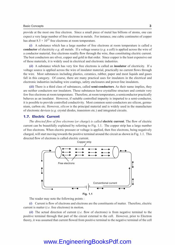
1.7. Electric C urrent The directed flow of free electrons (or charge) is called electric current.Theflowofelectriccurrent can be beautifully explained by referring to Fig. 1.1. The copper strip has a large number of free electrons. When electric pressure or voltage is applied, then free electrons, being negatively charged, will start moving towards the positive terminal around the circuit as shown in Fig. 1.1. This directedflowofelectronsiscalledelectriccurrent.
Fig. 1.1 The reader may note the following points : (i) Currentisflowofelectronsandelectronsaretheconstituentsofmatter.Therefore,electriccurrent is matter (i.e. free electrons) in motion. (ii) The actual direction of current (i.e. flowof electrons) is fromnegative terminal to thepositive terminal through that part of the circuit external to the cell. However, prior to Electron theory,itwasassumedthatcurrentflowedfrompositiveterminaltothenegativeterminalofthecell
www.EngineeringBooksPdf.com

4 Basic Electrical Engineering
viathecircuit.Thisconventionissofirmlyestablishedthatitisstillinuse.Thisassumeddirectionof current is now called conventional current. Unit of Current. The strength of electric current Iistherateofflowofelectronsi.e. charge flowingpersecond. \ Current, I =
Qt
The charge Q is measured in coulombs and time t in seconds. Therefore, the unit of electric current will be coulombs/sec or ampere. If Q = 1 coulomb, t = 1 sec, then I = 1/1 = 1 ampere. One ampere of current is said to flow through a wire if at any cross-section one coulomb of charge flows in one second. Thus,if5amperescurrentisflowingthroughawire,itmeansthat5coulombspersecondflowpast any cross-section of the wire. Note. 1 C = charge on 625 × 1016 electrons. Thus when we say that current through a wire is 1 A, it means that 625 × 1016electronspersecondflowpastanycross-sectionofthewire.
\ I = Q net t
= where e = – 1.6 × 10⁻¹⁹ C ; n = number of electrons
1.8. Electric Current is a Scalar Quantity
(i) Electric current, I = Qt
As both charge and time are scalars, electric current is a scalar quantity. (ii) We show electric current in a wire by an arrow to indicate the direction of flowof positive charge. But sucharrows are not vectors because they do not obey the laws of vector algebra. This point can be explained by referring to Fig. 1.2. The wires OA and OB carry currents of 3 A and 4 A respectively. The total current in the wire CO is 3 + 4 = 7 A ir-respective of the angle between the wires OA and OB. This is not surprising because the charge is conserved so that the magnitudes of currents in wires OA and OB must add to give the magnitude of current in the wire CO.
1.9. Types of Electric C urrent Theelectriccurrentmaybeclassified into threemainclasses: (i) steady current (ii) varying current and (iii) alternating current. (i) Steady current. When the magnitude of current does not change with time, it is called a steady current. Fig. 1.3 (i) shows the graph between steady current and time. Note that value of current remains the same as the time changes. The current provided by a battery is almost a steady current (d.c.).
Fig. 1.3
Fig. 1.2
www.EngineeringBooksPdf.com

Basic Concepts 5
(ii) Varying current. When the magnitude of current changes with time, it is called a varying current. Fig. 1.3 (ii) shows the graph between varying current and time. Note that value of current varies with time. (iii) Alternating current. An alternating current is one whose magnitude changes contin-uously with time and direction changes periodically. Due to technical and economical reasons, we produce alternating currents that have sine waveform (or cosine waveform) as shown in Fig. 1.3 (iii). It is called alternating current becausecurrentflowsinalternatedirectionsinthecircuit,i.e., from 0 to T/2 second (T is the time period of the wave) in one direction and from T/2 to T second in the opposite direction. The current provided by an a.c. generator is alternating current that has sine (or cosine) waveform.
1.10. Mechanism of Current Conduction in Metals Every metal has a large number of free electrons which wander randomly within the body of the conductorsomewhatlikethemoleculesinagas.Theaveragespeedoffreeelectronsissufficientlyhigh ( 105 ms–1) at room temperature. During random motion, the free electrons collide with posi-tive ions (positive atoms of metal) again and again and after each collision, their direction of motion changes. When we consider all the free electrons, their random motions average to zero. In other words,thereisnonetflowofcharge(electrons)inanyparticulardirection.Consequently,nocurrentis established in the conductor. When potential difference is applied across the ends of a conductor (say copper wire) as shown in Fig.1.4,electricfieldisappliedateverypointofthecopperwire.Theelectricfieldexertsforceonthefreeelectrons which start accelerating towards the positive terminal (i.e.,oppositetothedirectionofthefield).Asthe free electrons move, they *collide again and again with positive ions of the metal. Each collision destroys the extra velocity gained by the free electrons. The average time that an electron spends between two collisions is called the relaxation time (t). Its value is of the order of 10–14 second. Althoughthefreeelectronsarecontinuouslyacceleratedbytheelectricfield,collisionspreventtheirvelocityfrombecominglarge.Theresultisthatelectricfieldprovidesasmallconstantvelocitytowards positive terminal which is superimposed on the random motion of the electrons. This con-stant velocity is called the drift velocity. The average velocity with which free electrons get drifted in a metallic conductor under the influence of electric field is called drift velocity ( )dv
→. The drift velocity of free electrons is of the
order of 10–5 ms–1. Thuswhenametallicconductorissubjectedtoelectricfield(orpotentialdifference),freeelec-trons move towards the positive terminal of the source with drift velocity dv→ . Small though it is, the drift velocity is entirely responsible for electric current in the metal. Note. The reader may wonder that if electrons drift so slowly, how room light turns on quickly when switchisclosed?Theansweristhatpropagationofelectricfieldtakesplacewiththespeedoflight.Whenweapplyelectricfield(i.e., potential difference) to a wire, the free electrons everywhere in the wire begin drifting almost at once.
Fig. 1.4
* What happens to an electron after collision with an ion ? It moves off in some new and quite random direction. However, itstillexperiencestheappliedelectricfield,soitcontinuestoaccelerateagain,gaininga velocity in the direction of the positive terminal. It again encounters an ion and loses its directed motion. This situation is repeated again and again for every free electron in a metal.
www.EngineeringBooksPdf.com
6 Basic Electrical Engineering
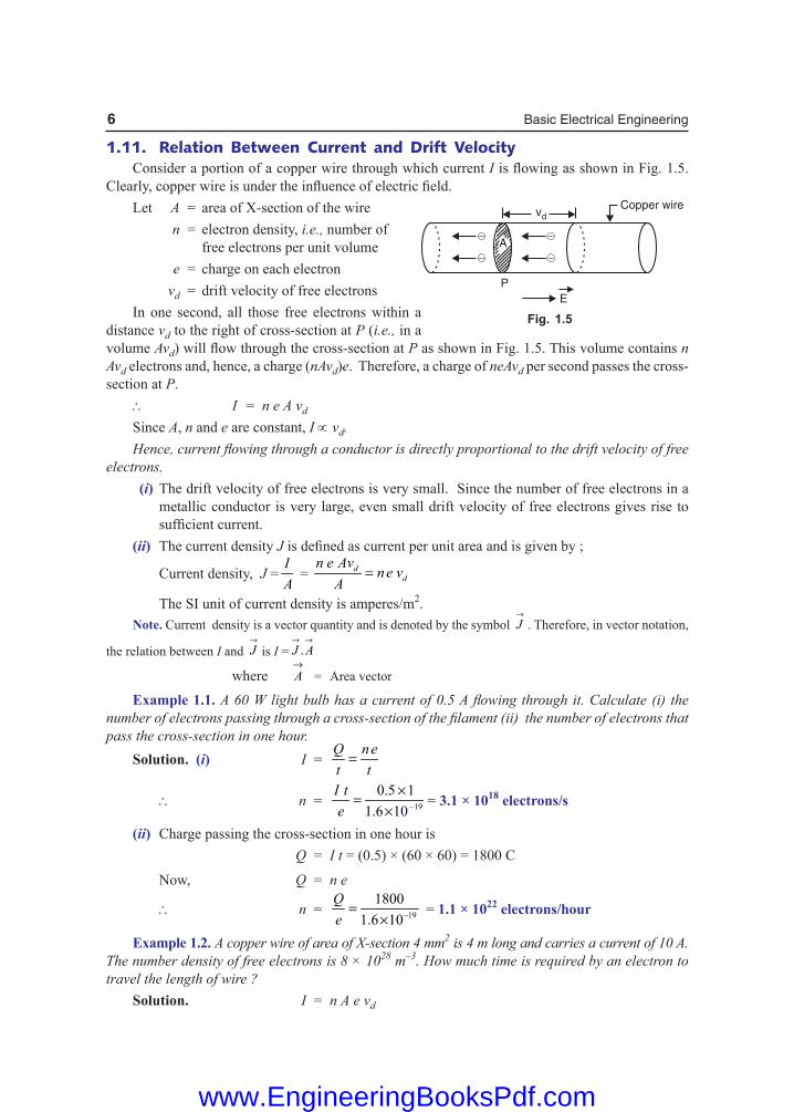
1.11. Relation Between Current and Drift Velocity Consider a portion of a copper wire through which current IisflowingasshowninFig.1.5.Clearly,copperwireisundertheinfluenceofelectricfield. Let A = area of X-section of the wire n = electron density, i.e., number of free electrons per unit volume e = charge on each electron vd = drift velocity of free electrons In one second, all those free electrons within a distance vd to the right of cross-section at P (i.e., in a volume Avd)willflowthroughthecross-sectionatP as shown in Fig. 1.5. This volume contains n Avd electrons and, hence, a charge (nAvd)e. Therefore, a charge of neAvd per second passes the cross-section at P. \ I = n e A vd
Since A, n and e are constant, I ∝ vd. Hence, current flowing through a conductor is directly proportional to the drift velocity of free electrons. (i) The drift velocity of free electrons is very small. Since the number of free electrons in a
metallic conductor is very large, even small drift velocity of free electrons gives rise to sufficientcurrent.
(ii) The current density Jisdefinedascurrentperunitareaandisgivenby;
Current density, J = IA
= dd
n e Avne v
A=
The SI unit of current density is amperes/m2. Note. Current density is a vector quantity and is denoted by the symbol
→J . Therefore, in vector notation,
the relation between I and →J is I = .
→ →J A
where →A = Area vector
Example 1.1. A 60 W light bulb has a current of 0.5 A flowing through it. Calculate (i) the number of electrons passing through a cross-section of the filament (ii) the number of electrons that pass the cross-section in one hour. Solution. (i) I =
Q net t
=
\ n = —19
0.5 1
1.6 1 0
I te
×=×
= 3.1 × 10¹⁸ electrons/s
(ii) Charge passing the cross-section in one hour is Q = I t = (0.5) × (60 × 60) = 1800 C
Now, Q = n e
\ n = —19
1800
1.6 10
Qe
=×
= 1.1 × 10²² electrons/hour
Example 1.2. A copper wire of area of X-section 4 mm2 is 4 m long and carries a current of 10 A. The number density of free electrons is 8 × 1028 m–3. How much time is required by an electron to travel the length of wire ? Solution. I = n A e vd
Fig. 1.5
www.EngineeringBooksPdf.com

Basic Concepts 7
Here I = 10 A ; A = 4 mm2 = 4 × 10⁻⁶ m2 ; e = 1.6 × 10⁻¹⁹ C ; n = 8 × 1028 m–3
\ Drift velocity, vd = —4 —1
28 —6 —19
101.95 10 ms
8 10 (4 10 ) 1.6 10
In A e
= = ×× × × × ×
\ Time taken by the electron to travel the length of the wire is
t = 4—4
42.05 10 s
1.95 10d
lv
= = ××
= 5.7 hours
Example 1.3. The area of X-section of copper wire is 3 × 10⁻⁶ m2. It carries a current of 4.2 A. Calculate (i) current density in the wire and (ii) the drift velocity of electrons. The number density of conduction electrons is 8.4 × 1028 m–3. Solution. (i) Current density, J = —6
4.2
3 10
IA
=×
= 1.4 × 10⁶ A/m2
(ii) I = n e A vd
\ Drift velocity, vd = 28 —19 —6
4.2
(8.4 10 ) (1.6 10 ) 3 10
In A e
=× × × × ×
= 1.04 × 10⁻⁴ ms–1
Tutorial Problems
1. Howmuchcurrentisflowinginacircuitwhere1.27×1015 electrons move past a given point in 100 ms ? [2.03 A]
2. The current in a certain conductor is 40 mA. (i) Find the total charge in coulombs that passes through the conductor in 1.5 s. (ii) Find the total number of electrons that pass through the conductor in that time. [( i) 60 mC (ii) 3.745 × 10¹⁷ electrons] 3. The density of conduction electrons in a wire is 1022 m–3. If the radius of the wire is 0.6 mm and it is
carrying a current of 2 A, what will be the average drift velocity ? [1.1 × 10⁻³ ms–1] 4. Findthevelocityofchargeleadingto1Acurrentwhichflowsinacopperconductorofcross-section
1 cm2 and length 10 km. Free electron density of copper = 8.5 × 1028 per m3. How long will it take the electric charge to travel from one end of the conductor to the other ? [0.735 mm/s; 431 years]
1.12. Electric Potential When a body is charged, work is done in charging it. This work done is stored in the body in the form of potential energy. The charged body has the capacity to do work by moving other charges either by attraction or repulsion. The ability of the charged body to do work is called electric potential. The capacity of a charged body to do work is called its electric potential. The greater the capacity of a charged body to do work, the greater is its electric potential. Obviously, the work done to charge a body to 1 coulomb will be a measure of its electric potential i.e. Electric potential, V =
Work done
Charge
WQ
=
The work done is measured in joules and charge in coulombs. Therefore, the unit of electric potential will be joules/coulomb or volt. If W = 1 joule, Q = 1 coulomb, then V = 1/1 = 1 volt. Hence a body is said to have an electric potential of 1 volt if 1 joule of work is done to give it a charge of 1 coulomb. Thus, when we say that a body has an electric potential of 5 volts, it means that 5 joules of work has been done to charge the body to 1 coulomb. In other words, every coulomb of charge possesses an energy of 5 joules. The greater the joules/coulomb on a charged body, the greater is its electric potential.
www.EngineeringBooksPdf.com

8 Basic Electrical Engineering
1.13. Potential Difference The difference in the potentials of two charged bodies is called potential difference. If two bodies have different electric potentials, a potential difference exists between the bodies. Consider two bodies A and B having potentials of 5 volts and 3 volts respectively as shown in Fig. 1.6 (i). Each coulomb of charge on body A has an energy of 5 joules while each coulomb of charge on body B has an energy of 3 joules. Clearly, body A is at higher potential than the body B.
Fig. 1.6 If the two bodies are joined through a conductor [See Fig. 1.6 (ii)],thenelectronswill*flowfrom body B to body A.Whenthetwobodiesattainthesamepotential,theflowofcurrentstops.Therefore,wearriveataveryimportantconclusionthatcurrentwillflowinacircuitifpotentialdifferenceexists.Nopotentialdifference,nocurrentflow.Itmaybenotedthatpotentialdifferenceis sometimes called voltage. Unit. Since the unit of electric potential is volt, one can expect that unit of potential difference will also be volt.Itisdefinedasunder: The potential difference between two points is 1 volt if one joule of work is **done or released in transferring 1 coulomb of charge from one point to the other.
1.14. Maintaining Potential Difference A device that maintains potential difference between two points is said to develop electromotive force (e.m.f.). A simple example is that of a cell. Fig. 1.7 shows the familiar voltaic cell. It consists of a copper plate (called anode) and a zinc rod (called cathode) immersed in dilute H2SO4. The chemical action taking place in the cell removes electrons from copper plate and transfers them to the zinc rod. This transference of electrons takes place through the agency of dil. H2SO4 (called electrolyte). Consequently, the copper plate attains a positive charge of +Q coulombs and zinc rod a charge of –Q coulombs. The chemical action of the cell has done a certain amount of work (say W joules) to do so. Clearly, the potential difference between the two plates will be W/Q volts. If the two plates are joined through a wire, some electrons from zinc rod will be attracted through the wire to copper plate. The chemical action of the cell now transfers an equal amount of electrons from copper plate to zinc rod internally through the cell to maintain original potential difference (i.e. W/Q). This process continues so long as the * The conventional currentflowwill be in theopposite direction i.e. from body A to body B.** 1 joule of work will be done in the case if 1 coulomb is transferred from point of lower potential to that of
higher potential. However, 1 joule of work will be released (as heat) if 1 coulomb of charge moves from a point of higher potential to a point of lower potential.
Fig. 1.7
www.EngineeringBooksPdf.com

Basic Concepts 9
circuitiscompleteorsolongasthereischemicalenergy.Theflowofelectronsthroughtheexternal wire from zinc rod to copper plate is the electric current. Thuspotentialdifferencecausescurrenttoflowwhileane.m.f. maintains the potential differ-ence. Although both e.m.f. and p.d. are measured in volts, they do not mean exactly the same thing.
1.15. Concept of E.M.F. and Potential Difference There is a distinct difference between e.m.f. and potential difference. The e.m.f. of a device, say a battery, is a measure of the energy the battery gives to each coulomb of charge. Thus if a battery supplies 4 joules of energy per coulomb, we say that it has an e.m.f. of 4 volts. The energy given to each coulomb in a battery is due to the chemical action. The potential difference between two points, say A and B, is a measure of the energy used by one coulomb in moving from A to B. Thus if potential difference between points A and B is 2 volts, it means that each coulomb will give up an energy of 2 joules in moving from A to B. Illustration. The difference between e.m.f. and p.d. can be made more illustrative by referring to Fig. 1.8. Here battery has an e.m.f. of 4 volts. It means battery supplies 4 joules of energy to each coulomb continuously. As each coulomb travels from the positive terminal of the battery, it gives up its most of energy to resistances (2 W and 2 W in this case) and remaining to connecting wires. When it returns to the negative terminal, it has lost all its energy originally supplied by the battery. The battery now supplies fresh energy to each coulomb (4 joules in the present case) to start the journey once again. The p.d. between any two points in the circuit is the energy used by one coulomb in moving from one point to another. Thus in Fig. 1.8, p.d. between A and B is 2 volts. It means that 1 coulomb will give up an energy of 2 joules in moving from A to B. This energy will be released as heat from the part AB of the circuit. The following points may be noted carefully : (i) Thenamee.m.f.atfirstsightimpliesthatitisaforcethatcausescurrenttoflow.Thisisnotcorrect because it is not a force but energy supplied to charge by some active device such as a battery. (ii) Electromotive force (e.m.f.) maintains potential difference while p.d. causes current to flow.
1.16. Potential Rise and Potential Drop Fig. 1.9 shows a circuit with a cell and a resistor. The cell provides a potential difference of 1.5 V. Since it is an energy source, there is a rise in potential associated with a cell. The cell’s potential difference represents an e.m.f. so that symbol E could be used. The resistor is also associated with a potential difference. Since it is a consumer (converter) of energy, there is a drop in potential across the resistor. We can combine the idea of potential rise or drop with the popular term “voltage”. It is customary to refer to the potential difference across the cell as a voltage rise and to the potential difference across the resistor as a voltage drop.
Fig. 1.8
+
–
1.5 V( )DROP
E = 1.5 V( )RISE
Fig. 1.9
www.EngineeringBooksPdf.com

10 Basic Electrical Engineering
Note. The term voltage refers to a potential difference across two points. There is no such thing as a voltageatonepoint.Incaseswhereasinglepointisspecified,somereferencemustbeusedastheotherpoint. Unless stated otherwise, the ground or common point in any circuit is the reference when specifying a voltage at some other point. Example 1.4. A charge of 4 coulombs is flowing between points A and B of a circuit. If the potential difference between A and B is 2 volts, how many joules will be released by part AB of the circuit ? Solution. The p.d. of 2 volts between points A and B means that each coulomb of charge will give up an energy of 2 joules in moving from A to B.Asthechargeflowingis4coulombs,therefore,total energy released by part AB of the circuit is = 4 × 2 = 8 joules. Example 1.5. How much work will be done by an electric energy source with a potential differ-ence of 3 kV that delivers a current of 1 A for 1 minute ? Solution. We know that 1 A of current represents a charge transfer rate of 1 C/s. Therefore, the total charge for a period of 1 minute is Q = It = 1 × 60 = 60 C. Total work done, W = Q × V = 60 × (3 × 103) = 180 × 103 J = 180 kJ
Tutorial Problems
1. Calculate the potential difference of an energy source that provides 6.8 J for every milli-coulomb of charge that it delivers. [6.8 kV]
2. The potential difference across a battery is 9 V. How much charge must it deliver to do 50 J of work ? [5.56 C]
3. A 300 V energy source delivers 500 mA for 1 hour. How much energy does this represent ? [540 kJ]
1.17. Resistance The opposition offered by a substance to the flow of electric current is called its resistance. Sincecurrentistheflowoffreeelectrons,resistanceistheoppositionofferedbythesubstancetotheflowoffreeelectrons.Thisoppositionoccursbecauseatomsandmoleculesofthesubstanceobstructtheflowoftheseelectrons.Certainsubstances(e.g. metals such as silver, copper, aluminium etc.)offerverylittleoppositiontotheflowofelectriccurrentandarecalledconductors.Ontheotherhand,thosesubstanceswhichofferhighoppositiontotheflowofelectriccurrent(i.e.flowoffreeelectrons) are called insulators e.g. glass, rubber, mica, dry wood etc. It may be noted here that resistance is the electric friction offered by the substance and causes productionofheatwiththeflowofelectriccurrent.Themovingelectronscollidewithatomsormolecules of the substance ; each collision resulting in the liberation of minute quantity of heat. Unit of resistance. The practical unit of resistance is ohm and is represented by the symbol W. Itisdefinedasunder: A wire is said to have a resistance of 1 ohm if a p.d. of 1 volt across its ends causes 1 ampere to flow through it (See Fig. 1.10). Thereisanotherwayofdefiningohm. A wire is said to have a resistance of 1 ohm if it releases 1 joule (or develops 0.24 calorie of heat) when a current of 1 A flows through it for 1 second. A little reflection shows that second definition leads to the first definition. Thus 1 A current flowing for 1 second means that total charge flowing is Q = I × t = 1 × 1 = 1 coulomb. Now the charge flowing between A and B (See Fig. 1.10) is 1 coulomb and energy released is 1 joule (or 0.24 calorie). Obviously, by definition, p.d. between A and B should be 1 volt.
Fig. 1.10
www.EngineeringBooksPdf.com

Basic Concepts 11
1.18. Factors Upon Which Resistance Depends The resistance R of a conductor (i) is directly proportional to its length i.e. R ∝ l (ii) is inversely proportional to its area of X-section i.e.
R ∝ 1
a
(iii) depends upon the nature of material. (iv) depends upon temperature. Fromthefirstthreepoints(leavingtemperatureforthetimebeing),wehave,
R ∝ la
or R = la
ρ
whereρ(Greekletter‘Rho’)isaconstantandisknownasresistivity or specific resistance of the material. Its value depends upon the nature of the material.
1.19. Specific Resistance or Resistivity
We have seen above that R = la
ρ
If l = 1 m, a = 1 m2, then, R = ρ Hence specific resistance of a material is the resistance offered by 1 m length of wire of material having an area of cross-section of 1 m2 [See Fig. 1.11 (i)].
Current
1 m
1 m
1 m
1 m2
1 m
( )i ( )iiFig. 1.11
Specificresistancecanalsobedefinedinanotherway.Takeacubeofthematerialhavingeachside 1 m. Considering any two opposite faces, the area of cross-section is 1 m2 and length is 1 m [See Fig. 1.11 (ii)] i.e. l = 1 m, a = 1 m2. Hence specific resistance of a material may be defined as the resistance between the opposite faces of a metre cube of the material. Unit of resistivity. We know R =
laρ
or ρ=R al
Hence the unit of resistivity will depend upon the units of area of cross-section (a) and length (l). (i) If the length is measured in metres and area of cross-section in m2, then unit of resistivity willbeohm-metre(Ωm).
ρ =2ohm × m
ohm-mm
=
www.EngineeringBooksPdf.com

12 Basic Electrical Engineering
(ii) If length is measured in cm and area of cross-section in cm2, then unit of resistivity will be ohm-cm(Ωcm). ρ=
2ohm cm
cm
× = ohm-cm
The resistivity of substances varies over a wide range. To give an idea to the reader, the follow-ing table may be referred :
S.No. Material Nature Resistivity (W-m) at room temperature
1 Copper metal 1.7 ×10⁻⁸
2 Iron metal 9.68 × 10⁻⁸
3 Manganin alloy 48 × 10–8
4 Nichrome alloy 100 × 10–8
5 Pure silicon semiconductor 2.5 ×10³
6 Pure germanium semiconductor 0.67 Glass insulator 1010 to 1014
8 Mica insulator 1011 to 1015
The reader may note that resistivity of metals and alloys is very small. Therefore, these materials are good conductors of electric current. On the other hand, resistivity of insulators is extremely large. As a result, these materials hardly conduct any current. There is also an intermediate class of semiconductors. The resistivity of these substances lies between conductors and insulators.
1.20. Conductance The reciprocal of resistance of a conductor is called its conductance (G). If a conductor has resistance R, then its conductance G is given by ; G = 1/R Whereas resistance of a conductor is the opposition to current flow, the conductance of aconductoristheinducementtocurrentflow. The SI unit of conductance is mho (i.e., ohm spelt backward). These days, it is a usual practice to use siemen as the unit of conductance. It is denoted by the symbol S. Conductivity. The reciprocal of resistivity of a conductor is called its conductivity. It is denotedbythesymbolσ.Ifaconductorhasresistivityρ,thenitsconductivityisgivenby;
Conductivity, σ = 1
ρ We know that G =
1 .a aR l l
= = σρ
Clearly, the SI unit of conductivity is Siemen metre−1 (S m−1).
Example 1.6. A coil consists of 2000 turns of copper wire having a cross-sectional area of 0.8 mm2. The mean length per turn is 80 cm and the resistivity of copper is 0.02 mW m. Find the resistance of the coil and power absorbed by the coil when connected across 110 V d.c. supply. Solution. Length of coil, l = 0.8 × 2000 = 1600 m; cross-sectional area of coil, a = 0.8 mm2 = 0.8 × 10⁻⁶m2; Resistivity of copper, ρ = 0.02 × 10⁻⁶ Wm
\ Resistance of coil, R = la
ρ = 0.02 × 10⁻⁶ —6
1600
0.8 10× = 40 W
Power absorbed, P = 2V
R =
2(110)
40 = 302.5 W
www.EngineeringBooksPdf.com

Basic Concepts 13
Example 1.7. Find the resistance of 1000 metres of a copper wire 25 sq. mm in cross-section. The resistance of copper is 1/58 ohm per metre length and 1 sq. mm cross-section. What will be the resistance of another wire of the same material, three times as long and one-half area of cross-section ? Solution.Forthefirstcase,R1 = ? ; a1 = 25 mm2 ; l1 = 1000 m For the second case, R2 = 1/58 W ; a2 = 1 mm2 ; l2 = 1 m R1 = ρ(l1/a1) ; R2=ρ(l2/a2)
\ 1
2
RR
= 1 2
2 1
000 140
1 25
l al a
1 × = × =
or R1 = 40 R2 = 40 × 1
58=
2029
W
For the third case, R3 = ? ; a3 = a1/2 ; l3 = 3l1
\ 3
1
RR
= 3 1
1 3
l al a
×
= (3) × (2) = 6
or R3 = 6R1 = 6 × 20
29 =
12029
W
Example 1.8. A copper wire of diameter 1 cm had a resistance of 0.15 Ω. It was drawn under pressure so that its diameter was reduced to 50%. What is the new resistance of the wire ?
Solution. Area of wire before drawing, a1 = 4
π (1)2 = 0.785 cm2
Area of wire after drawing, a2 = 4
π (0.5)2 = 0.196 cm2
As the volume of wire remains the same before and after drawing, \ a1l1 = a2l2 or l2/l1 = a1/a2 = 0.785/0.196 = 4 Forthefirstcase, R1 = 0.15Ω;a1 = 0.785 cm2 ; l1 = l For the second case, R2 = ? ; a2 = 0.196 cm2 ; l2 = 4l
Now R1 = 1
1
;la
ρ R2 = 2
2
la
ρ
\ 2
1
RR
= 2 1
1 2
l al a
×
= (4) × (4) = 16
or R2 = 16R1 = 16 × 0.15 = 2.4 Ω Example 1.9. Two wires of aluminium and copper have the same resistance and same length. Which of the two is lighter? Density of copper is 8.9 × 10³ kg/m3 and that of aluminium is 2.7 × 10³ kg/m3. The resistivity of copper is 1.72 × 10⁻⁸ Ω m and that of aluminium is 2.6 × 10⁻⁸ Ω m. Solution.Thatwirewillbelighterwhichhaslessmass.Letsuffix1representaluminiumandsuffix2representcopper. R1 = R2 or 1 2
1 21 2
l lA A
ρ = ρ
or 1
1Aρ
= 2
2Aρ
( l1 = l2)
or 1
2
AA
= —8
1—8
2
.6 101.5
1.72 10
ρ 2 ×= =ρ ×
www.EngineeringBooksPdf.com
14 Basic Electrical Engineering
Now 1
2
mm
= 1 1 1 1 1
2 2 2 2 2
( )
( )
A l d A dA l d A d
= ( l1 = l2)
or 1
2
mm
=3
1 13
2 2
2.7 101.5
8.9 10
A dA d
×× = × ×
= 0.46
or m1/m2 = 0.46 It is clear that for the same length and same resistance, aluminium wire is lighter than copper wire. For this reason, aluminium wires are used for overhead power transmission lines. Example 1.10. A rectangular metal strip has the dimensions x = 10 cm, y = 0.5 cm and z = 0.2 cm. Determine the ratio of the resistances Rx, Ry and Rz between the respective pairs of opposite faces. Solution. Rx : Ry : Rz = : :
ρ ρ ρx y zyz zx xy
= 10 0.5 0.2
: :0.5 0.2 0.2 10 10 0.5× × ×
= 10 1
: : 0.040.1 4
= 2500 : 6.25 : 1
Example 1.11. Calculate the resistance of a copper tube 0.5 cm thick and 2 m long. The external diameter is 10 cm. Given that resistance of copper wire 1 m long and 1 mm2 in cross-section is 1/58 Ω. Solution. External diameter, D = 10 cm Internal diameter, d = 10 – 2 × 0.5 = 9 cm
Area of cross-section, a = 2 2 2 2 2( ) (10) (9) cm4 4
D dπ π − = −
= 2 2 2(10) (9) 100 mm4
π − ×
\ Resistance of copper tube = 2
1 length in metres
58 area of X-section in mm
laρ = ×
= 2 2
1 2
58 (10) (9) 1004
×π − ×
= 23.14 × 10⁻⁶Ω=23.14 µΩ
Example 1.12. A copper wire is stretched so that its length is increased by 0.1%. What is the percentage change in its resistance ?
Solution. R = la
ρ ; R′=la′ρ′
Now l′ =0.1
100l l+ × = 1.001 l
As the volume remains the same, al = a′l′.
\ a′ =1.001
l aal
=′
\ RR
′ =
l al a′ × ′
= (1.001) × (1.001) = 1.002
or R R
R′ −
= 0.002
\ Percentage increase = 100R R
R′ − × = 0.002 × 100 = 0.2%
www.EngineeringBooksPdf.com

Basic Concepts 15
Example 1.13. A lead wire and an iron wire are connected in parallel. Their respective specific resistances are in the ratio 49 : 24. The former carries 80% more current than the latter and the latter 47% longer than the former. Determine the ratio of their cross-sectional areas. Solution.Letusrepresentleadandironbysuffixes1and2respectively.Thenasperthecondi-tions of the problem, we have,
1
2
ρρ
= 49
24 ; I1 = 1.8 I2 ; l2 = 1.47 l1
Now R1 = 11
1
ρla
; R2 = 22
2
la
ρ
I1 = 1
VR
and I2 = 2
VR
\ 2
1
II
= 1 1 1 2 1 1 2
2 1 2 2 2 2 1
R l a l aR a l l a
ρ ρ= × = × × ρ ρ
or 1
1.8 = 2
1
49 1
24 1.47
aa
× ×
\ 2
1
aa
= 1 24
1.471.8 49
× × = 0.4
Example 1.14. An aluminium wire 7.5 m long is connected in parallel with a copper wire 6 m long. When a current of 5 A is passed through the combination, it is found that the current in the aluminium wire is 3 A. The diameter of the aluminium wire is 1 mm. Determine the diameter of the copper wire. Resistivity of copper is 0.017 µΩm ; that of the aluminium is 0.028 µΩ m. Solution. Let us assign subscripts a and c to aluminium and copper respectively. Current through Al wire, Ia = 3 A \ Current through Cu wire, Ic = 5 – 3 = 2 A Since Ra and Rc are in parallel, the voltage across them is the same [See Fig. 1.12] i.e.
Ia Ra = Ic Rc or 2
3a c
c a
R IR I
= =
Now Ra = a a
a
la
ρ ; Rc = c c
c
la
ρ
\ c
a
RR
= c c a
a a c
l al a
ρ× ×
ρ
Here c
a
RR
= 0.017 6
; ; ;2 0.028 7.5
3 ρ= =
ρc c
a a
ll
aa = 2
2 2(1)mm
4 4 4
π π× π= =d
\ 3
2 =
0.017 6 / 4
0.028 7.5 caπ× ×
or ac = 2 0.017 6
3 0.028 7.5 4
π× × × = 0.2544 mm2
or 2
4 cdπ = 0.2544 \ dc = 0.569 mm
Fig. 1.12
www.EngineeringBooksPdf.com

16 Basic Electrical Engineering
Example 1.15. A transmission line cable consists of 19 strands of identi-cal copper conductors, each 1.5 mm in diameter. The length of the cable is 2 km but because of the twist of the strands, the actual length of each conductor is increased by 5 percent. What is resistance of the cable ? Take the resistivity of the copper to be 1.78 × 10⁻⁸ Ω m. Solution. Fig. 1.13 shows the general shape of a stranded conductor. Allowing for twist, the length of the strands is l = 2000 m + 5% of 2000 m = 2100 m
Area of X-section of 19 strands, a = —3 2 —6 2(19) (1.5 10 ) 33.576 10 m4
π × × = ×
\ Resistance of line, R = —8—6
21001.72 10
33.576 10
la
ρ = × ××
= 1.076 Ω
Example 1.16. The resistance of the wire used for telephone is 35 Ω per kilometre when the weight of the wire is 5 kg per kilometre. If the specific resistance of the material is 1.95 × 10⁻⁸ Ω m, what is the cross-sectional area of the wire ? What will be the resistance of a loop to a subscriber 8 km from the exchange if wire of the same material but weighing 20 kg per kilometre is used? Solution.Forthefirstcase,R = 35Ω ; l=1000m ; ρ=1.95×10⁻⁸Ωm
Now R = la
ρ \ a = —81.95 10 1000
35
lRρ × ×= = 55.7 × 10⁻⁸ m2
Since weight of conductor is directly proportional to the area of cross-section, for the second case, we have,
a = 20
5 × 55.7 × 10–8 = 222.8 × 10⁻⁸ m2 ; l = 2 × 8 = 16 km = 16000 m
\ R = la
ρ = 1.95 × 10⁻⁸ × —8
16000
222.8 10× = 140.1 Ω
Example 1.17. Find the resistance of a cubic centimetre of copper (i) when it is drawn into a wire of diameter 0.32 mm and (ii) when it is hammered into a flat sheet of 1.2 mm thickness, the current flowing through the sheet from one face to another, specific resistance of copper is 1.6 × 10⁻⁸ W-m. Solution. Volume of copper wire, v = 1 cm3 = 1 × 10⁻⁶ m3
(i) Resistance when drawn into wire.
Area of X-section, a = 2 —3 2(0.32 10 )4 4
dπ π= × = 0.804 × 10⁻⁷ m2
Length of wire, l = —6
—7
1 1012.43m
0.804 10
va
×= =×
\ Resistance of wire, R = la
ρ = 1.6 × 10⁻⁸ —7
12.43
0.804 10× = 2.473 W
(ii) Resistance when hammered into flat sheet.
Length of f lat sheet, l = 1.2 × 10⁻³m;Areaofcross-sectionofflatsheetis
a = vl
=—6 —3
2
—3
1 10 10m
1.21.2 10
× =×
\ Resistance of copper flat sheet is R = —3
—8
—3
1.2 101.6 10
10 /1.2
la
×ρ = × = 2.3 × 10⁻⁸ W
Fig. 1.13
www.EngineeringBooksPdf.com

Basic Concepts 17
Tutorial Problems
1. Calculate the resistance of 915 metres length of a wire having a uniform cross-sectional area of 0.77 cm2 if the wire is made of copper having a resistivity of 1.7 × 10⁻⁶Ωcm. [0.08 Ω]
2. Awireoflength1mhasaresistanceof2ohms.Whatistheresistanceofsecondwire,whosespecificresistanceisdoublethefirst,ifthelengthofwireis3metresandthediameterisdoubleofthefirst?[3 Ω]
3. A rectangular copper strip is 20 cm long, 0.1 cm wide and 0.4 cm thick. Determine the resistance between (i) opposite ends (ii) opposite sides. The resistivity of copper is 1.7 × 10⁻⁶Ωcm.
[(i) 0.85 × 10⁻⁴ Ω (ii) 0.212 × 10⁻⁶ Ω] 4. Acubeofamaterialofside1cmhasaresistanceof0.001Ωbetweenitsoppositefaces.Ifthesame
material has a length of 9 cm and a uniform cross-sectional area 1 cm2, what will be the resistance of this length ? [0.009 Ω]
5. An aluminium wire 10 metres long and 2 mm in diameter is connected in parallel with a copper wire 6 metres long. A total current of 2 A is passed through the combination and it is found that current through thealuminiumwireis1.25A.Calculatethediameterofcopperwire.Specificresistanceofcopperis1.6 × 10–6Ωcmandthatofaluminiumis2.6×10–6Ωcm. [0.94 mm]
6. A copper wire is stretched so that its length is increased by 0.1%. What is the percentage change in its resistance ? [0.2%]
1.21. Types of Resistors A component whose function in a circuit is to provide a specified value of resistance is called a resistor. The principal applications of resistors are to limit current, divide voltage and in certain cases, generate heat. Although there are a variety of different types of resistors, the following are the commonly used resistors in electrical and electronic circuits : (i) Carbon composition types (ii) Film resistors (iii) Wire-wound resistors (iv) Cermet resistors (i) Carbon composition type. Thistypeofresistorismadewithamixtureoffinelygroundcarbon, insulatingfilleranda resinbinder. The ratioofcarbonand insulatingfillerdecides theresistance value [See Fig. 1.14]. The mixture is formed into a rod and lead connections are made. The entire resistor is then enclosed in a plastic case to prevent the entry of moisture and other harmful elements from outside.
Fig. 1.14
Carbon resistors are relatively inexpensive to build. However, they are highly sensitive to temperature variations. The carbon resistors are available in power ratings ranging from 1/8 to 2 W. (ii) Film resistors. Inafilmresistor,aresistivematerialisdepositeduniformlyontoahigh-gradeceramic rod. The resistivefilmmaybecarbon (carbonfilm resistor)ornickel-chromium(metalfilmresistor).Inthesetypesofresistors,thedesiredresistancevalueisobtainedbyremovinga part of the resistive material in a helical pattern along the rod as shown in Fig. 1.15.
www.EngineeringBooksPdf.com

18 Basic Electrical Engineering
Metal film resistors have bettercharacteristicsascompared tocarbonfilmresistors. (iii) Wire-wound resistors. A wire-wound resistor is constructed by winding a resistive wire of some alloy around an insulating rod. It is then enclosed in an insulating cover. Generally, nickle-chromium alloy is used because of its very smalltemperaturecoefficientofresistance.Wire-wound resistors can safely operate at higher temperatures than carbon types. These resistors have high power ratings ranging from 12 to 225 W. (iv) Cermet resistors. Acermet resistor ismadebydepositinga thinfilmofmetal suchasnichrome or chromium cobalt on a ceramic substrate. They are cermet which is a contraction for ceramic and metal. These resistors have very accurate values.
1.22. Effect of Temperature on Resistance In general, the resistance of a material changes with the change in temperature. The effect of temperature upon resistance varies according to the type of material as discussed below : (i) The resistance of pure metals (e.g. copper, aluminium) increases with the increase of temperature. The change in resistance is fairly regular for normal range of temperatures so that temperature/resistance graph is a straight line as shown in Fig. 1.16 (for copper). Since the resistance of metals increases with the rise in temperature, they have positive temperature co-efficient of resistance. (ii) The resistance of electrolytes, insulators (e.g. glass, mica, rubber etc.) and semiconductors (e.g. germanium, silicon etc.) decreases with the increase in temperature. Hence these materials have negative temperature co-efficient of resistance. (iii) The resistance of alloys increases with the rise in temperature but this increase is very small and irregular. For some high resistance alloys (e.g. Eureka, manganin, constantan etc.), the change in resistance is practically negligible over a wide range of temperatures. Fig. 1.16 shows temperature/resistance graph for copper which is a straight line. If this line is extendedbackward,itwouldcutthetemperatureaxisat−234.5°C. It means that theoretically, the resistanceofcopperwireiszeroat−234.5°C. However, in actual practice, the curve departs (point A) from the straight line path at very low temperatures.
1.23. Temperature Co-efficient of Resistance Consider a conductor having resistance R0 at 0°C and Rt at t °C. It has been found that in the normal range of temperatures, the increase in resistance (i.e. Rt−R0) (i) is directly proportional to the initial resistance i.e. Rt−R0 ∝ R0
Fig. 1.15
Fig. 1.16
www.EngineeringBooksPdf.com

Basic Concepts 19
(ii) is directly proportional to the rise in temperature i.e. Rt −R0 ∝ t (iii) depends upon the nature of material. Combiningthefirsttwo,weget, Rt−R0 ∝ R0 t or Rt−R0 = *a0 R0 t ...(i)where α0 is a constant and is called temperature co-efficient of resistance at 0°C. Its value depends upon the nature of material and temperature. Rearranging eq. (i), we get, Rt = R0(1+α0 t) ...(ii) Definition of a0. From eq. (i), we get,
a0 = 0
0
tR RR t
−×
= Increase in resistance/ohm original resistance/°C rise in tem- perature Hence temperature co-efficient of resistance of a conductor is the increase in resistance per ohm original resistance per °C rise in temperature. A little reflection shows that unit of a will be ohm/ohm°C i.e./°C. Thus, copper has a temperature co-efficient of resistance of 0.00426/°C. It means that if a copper wire has a resistance of 1 W at 0°C, then it will increase by 0.00426 W for 1°C rise in temperature i.e. it will become 1.00426 W at 1°C. Similarly, if temperature is raised to 10°C, then resistance will become 1 + 10 × 0.00426 = 1.0426 ohms. The following points may be noted carefully : (i) Those substances (e.g. pure metals) whose resistance increases with rise in temperature are said to have positivetemperatureco-efficientofresistance.Ontheotherhand,thosesubstanceswhose resistance decreases with increase in temperature are said to have negative temperature co-efficientofresistance. (ii) If a conductor has a resistance R0, R1 and R2 at 0oC, t1
oC and t2oC respectively, then,
R1 = R0 (1 + a0 t1)
R2 = R0 (1 + a0 t2)
\ 2
1
RR
= 0 2
0 11
tt
1+ α+ α
...(iii)
This relation is often utilised in determining the rise of temperature of the winding of an electrical machine. The resistance of the winding is measured both before and after the test run. Let R1 and t1 be the resistance and temperature before the commencement of the test. After the operation of the machine for a given period, let these values be R2 and t2. Since R1 and R2 can be measured and t1 (ambient temperature) and a0 are known, the value of t2 can be calculated from eq. (iii). The average rise in temperature of the winding will be (t2−t1)°C. Note. The life expectancy of electrical apparatus is limited by the temperature of its insulation; the higher the temperature, the shorter the life. The useful life of electrical apparatus reduces approximately by half every time the temperature increases by 10°C. This means that if a motor has a normal life expectancy of eight years
* It will be shown in Art. 1.25 that value of a depends upon temperature. Therefore, it is referred to the original temperature i.e. 0°C in this case. Hence the symbol a0.
www.EngineeringBooksPdf.com

20 Basic Electrical Engineering
at a temperature of 100°C, it will have a life expectancy of only four years at a temperature of 110°C, of two years at a temperature of 120°C and of only one year at 130°C.
1.24. Graphical Determination of a The value of temperature co-efficient ofresistance can also be determined graphically from temperature/resistance graph of the material. Fig. 1.17 shows the temperature/resistance graph for a conductor. The graph is a straight line AX as is the case with all conductors. The resistance of the conductor is R0 (represented by OA) at 0°C and it becomes Rt at t°C.Bydefinition,
a0 = 0
0
tR RR t
−×
But Rt−R0 = BC and t = rise in temperature = AB
\ a0 = 0
BCR AB×
But BC/AB is the slope of temperature/resistance graph.
\ α0 = Slope of temp./resistance graph
Original resistance ...(i)
Hence, temperature co-efficient of resistance of a conductor at 0°C is the slope of temp./resistance graph divided by resistance at 0°C (i.e. R0). The following points may be particularly noted : (i) Thevalueofαdependsupontemperature.Atanytemperature,a can be calculated by using
eq. (i). Thus, α0 =
0
Slope* of temperature/resistance graph
R
and αt = Slope of temperature/resistance graph
tR
(ii) The value of α0 is maximum and it decreases as the temperature is increased. This is clear from the fact that the slope of temperature/resistance graph is constant and R0 has the minimum value.
1.25. Temperature Co-efficient at Various Temperatures Consider a conductor having resistances R0 and R1 at temperatures 0°C and t1°C respectively. Let a0 and a1 be the temperature co-efficients of resistance of the conductor at 0°C and t1°C respectively. It is desired to establish the relationship between a1 and a0. Fig. 1.18 shows the temperature/resistance graph of the conductor. As proved in Art. 1.24,
a0 = 0
Slope of graph
R\ Slope of graph = a0 R0
Fig. 1.17
* The slope of temp./resistance graph of a conductor is always constant (being a straight line).
www.EngineeringBooksPdf.com

Basic Concepts 21
Similarly, a1 = 1
Slope of graph
Ror Slope of graph = a1 R1
Since the slope of temperature/resistance graph is constant, \ a0 R0 = a1 R1
or a1 = 0 0
1
RR
α = 0 0
0 0 1(1 )
RR t
α+ α
[ R1 = R0(1+α0 t1)]
\ a1 = 0 11 t
0α+ α
...(i)
Similarly,* a2 = 0
0 21 tα
+ α ...(ii)
Subtracting the reciprocal of eq. (i) from the reciprocal of eq. (ii),
2 1
1 1−α α
= 0 10 2
0 0
11 tt + α+ α −α α = t2−t1
\ a2 = 2 1
1
11 ( )t t+ −
α
...(iii)
Eq. (i)givestherelationbetweenα1andα0 while Eq. (iii)givestherelationbetweenα2andα1.
1.26. Summary of Temperature Co-efficient Relations
(i) If R0andα0aretheresistanceandtemperatureco-efficientofresistanceofaconductorat0oC, then its resistance Rt at t°C is given by ;
Rt = R0(1+α0 t) (ii) If a0, a1 and a2 are the temperature co-efficients of resistance at 0°C, t1°C and t2°C
respectively, then,
α1 = 0
0 11 tα
+ α;α2 = 0
0 21 tα
+ α;α2 =
2 11
11 ( )+ −
αt t
(iii) Suppose R1 and R2 are the resistances of a conductor at t1°C and t2°Crespectively.Ifα1 is thetemperatureco-efficientofresistanceatt1
oC, then, R2** = R1[1+α1(t2−t1)]
1.27. Variation of Resistivity With Temperature Notonly resistance but resistivity or specific resistance of amaterial also changeswithtemperature. The change in resistivity per °C change in temperature is called temperature
Fig. 1.18
* a0R0 = a2R2 where R2 is the resistance at t2°C
or a2 = 0 0 0 0 0
2 0 0 2 0 2(1 ) 1
R R
R R t t
α α α= =
+ α + α** Slope of graph, tan q = R0 a0 = R1 a1 = R2 a2
Increase in resistance as temperature is raised from t1°C to t2°C = tan q(t2 – t1) = R1a1(t2 – t1) \ Resistance at t2°C, R2 = R1 + R1a1(t2 – t1) = R1[1 + a1(t2 – t1)]
www.EngineeringBooksPdf.com

22 Basic Electrical Engineering
coefficient of resistivity. In case of metals, the resistivity increases with increase in temperature and vice-versa. It is found that resistivity of a metallic conductor increases linearly over a wide range of temperatures and is given by ; ρt = ρ0(1 + a0t) where ρ0 = resistivity of metallic conductor at 0°C ρt = resistivity of metallic conductor at temperature t°C Notethattemperaturecoefficientofresistivityisequaltotemperaturecoefficientofresis-tance a0. Example 1.18. A coil has a resistance of 18 W when its mean temperature is 20°C and of 20 W when its mean temperature is 50°C. Find its mean temperature rise when its resistance is 21W and the surrounding temperature is 15°C. Solution. Let R0 be the resistance of the coil at 0°C and a0beitstemperaturecoefficientofresistance at 0°C. Then, 18 = R0 (1 + a0 × 20) and 20 = R0 (1 + a0 × 50)
\ 20
18 = 0
0
1 50
1 20
+ α+ α
or a0 = 1
0.004/250
C= °
If t°C is the temperature of the coil when its resistance is 21W, then, 21 = R0 (1 + 0.004 t)
\ 21
18 = 0
0
(1 0.004 )
(1 0.004 20)
R tR
++ ×
or t = 65°C
\ Temperature rise = t – 15 = 65° – 15° = 50°C Example 1.19. The resistance of the field coils of a dynamo is 173 Ω at 16oC. After working for 6 hours on full-load, the resistance of the coils increases to 212 Ω. Calculate (i) the temperature of the coils (ii) mean rise of temperature of the coils. Assume temperature co-efficient of resistance of copper is 0.00426/oC at 0oC. Solution. (i) Let toCbethefinaltemperature.
16
t
RR
= 0 0
0 0
(1 16)
(1 )
RR t
+ α ×+ α ×
or 173
212 =
1 0.00426 16
1 0.00426 t+ ×+ ×
or 0.816 = 1.068
1 0.00426 t+ \ t = 72.5°C
(ii) Rise in temperature = t−16=72.5−16=56.5°C Example 1.20. The resistance of a transformer winding is 460 Ω at room temperature of 25oC. When the transformer is running and the final temperature is reached, the resistance of the winding increases to 520 Ω. Find the average temperature rise of winding, assuming that α20 = 1/250 per oC.
Solution. a25 = 20
1 1 1/
1/ (25 — 20) 250 5 255C= = °
α + +
Let toCbethefinaltemperatureofthewinding.Then,theriseintemperatureist−25. Now, R25 = 460Ω;Rt=520Ω Rt = R25[1+α25(t−25)]
or t−25 =25 25
11tR
R
− α =255(520/460−1)=33.26°C
\ Temperature rise = t−25=32.26°C
www.EngineeringBooksPdf.com

Basic Concepts 23
Example 1.21. The filament of a 60 watt, 230 V lamp has a normal working temperature of 2000oC. Find the current flowing in the filament at the instant of switching, when the lamp is cold. Assume the temperature of cold lamp to be 15°C and α15 = 0.005/oC. Solution. Resistance of lamp at 2000oC is R2000 = V2/P = (230)2/60=881.67Ω R2000 = R15[1+α15(2000−15)]
\ R15 = 2000 881.6780.7
1 0.005(1985) 10.925
R= = Ω
+ \ Current taken by cold lamp (i.e. at the time of switching) is I = V/R15 = 230/80.7 = 2.85 A Example 1.22. Two coils connected in series have resistances of 600 W and 300 W and temperature coefficients of 0.1% and 0.4% per °C at 20°C respectively. Find the resistance of combination at a temperature of 50°C. What is the effective temperature coefficient of the combination at 50°C ? Solution. Resistance of 600 W coil at 50°C = 600 [1 + 0.001(50 – 20)] = 618 W Resistance of 300 W coil at 50°C = 300 [1 + 0.004 (50 – 20)] = 336 W Resistance of series combination at 50°C is R50 = 618 + 336 = 954 W Resistance of series combination at 20°C is R20 = 600 + 300 = 900 W Now R50 = R20 [1 + a20 (t2 – t1)]
\ a20 =
50
20
2 1
9541 1900 0.00250 — 20
RRt t
− −= =
−
Now a50 = 20 2 1
1
1/ ( )t tα + − =
1
1/ 0.002 (50 20)+ − =
1 / °C530
Example 1.23. The coil of a relay takes a current of 0.12 A when it is at the room temperature of 15°C and connected across a 60 V supply. If the minimum operating current of the relay is 0.1 A, calculate the temperature above which the relay will fail to operate when connected to the same supply. Resistance temperature coefficient of the coil material is 0.0043 per °C at 0°C. Solution. Resistance of relay coil at 15°C, R15=60/0.12=500Ω If the temperature increases, the resistance of relay coil increases and current in relay coil de-creases. Let t°C be the temperature at which the current in relay coil becomes 0.1 A (= the minimum relay coil current for its operation). Clearly, Rt=60/0.1=600Ω. Now, R15 = R0(1+15α0) = R0 (1 + 15 × 0.0043) Rt = R0(1+α0t) = R0 (1 + 0.0043 t)
\ 15
tRR
= 1 0.0043
1.0645
t+
or 600
500 =
1 0.0043
1.0645
t+
On solving, t = 64.5°C
www.EngineeringBooksPdf.com

24 Basic Electrical Engineering
If the temperature of relay coil increases above 64.5°C, the resistance of relay coil will increase and the relay coil current will be less than 0.1 A. As a result, the relay will fail to operate. Example 1.24. Two materials, A and B, have resistance temperature coefficients of 0.004 and 0.0004 respectively at a given temperature. In what proportion must A and B be joined in series to produce a circuit having a temperature coefficient of 0.001 ? Solution. Let the resistance of Abe1ΩandthatofB be xΩi.e. RA=1ΩandRB = xΩ. Resistance of series combination = RA + RB = (1 + x)Ω Suppose the temperature rises by t°C. Resistance of series combination at the raised temperature = (1 + x) (1 + 0.001 t) ...(i) Resistance of A at the raised temperature = 1 (1 + 0.004 t) ...(ii) Resistance of B at the raised temperature = x (1 + 0.0004 t) ...(iii) As per the conditions of the problem, we have, (ii) + (iii) = (i) or 1 (1 + 0.004 t) + x (1 + 0.0004 t) = (1 + x) (1 + 0.001 t) or 0.004 t + 0.0004 t x = (1 + x) × 0.001 t Dividing by t and multiplying throughout by 104, we have, 40 + 4x = 10 (1 + x) \ x = 5 \ RA : RB = 1 : 5 i.e. RB should be 5 times RA. Example 1.25. A resistor of 80 Ω resistance, having a temperature coefficient of 0.0021/°C is to be constructed. Wires of two materials of suitable cross-sectional areas are available. For material A, the resis-tance is 80 Ω per 100 m and the temperature coefficient is 0.003/°C. For material B, the corresponding figures are 60 Ω per 100 m and 0.0015/°C. Calculate suitable lengths of wires of materials A and B to be connected in series to construct the required resistor. All data are referred to the same temperature. Solution. Let RA and RB be the required resistances of materials A and B respectively which whenjoinedinserieshaveacombinedtemperaturecoefficientof0.0021[SeeFig.1.19]. Resistance of series combination = RA + RB
Resistance of series combination at raised temperature = (RA + RB) (1 + 0.0021 t) ...(i) Resistance of A at raised temperature = RA (1 + 0.003 t) ...(ii) Resistance of B at raised temperature = RB (1 + 0.0015 t) ...(iii) As per conditions of the problem, (ii) + (iii) = (i). \ RA (1 + 0.003 t) + RB (1 + 0.0015 t) = (RA + RB) (1 + 0.0021 t)
On solving, B
A
RR
= 3
2 ...(iv)
Now, RA + RB = 80 ...(v) From eqs. (iv) and (v), RA = 32ΩandRB=48Ω \ Length of wire A, LA = (100/80) × 32 = 40 m Length of wire B, LB = (100/60) × 48 = 80 m Example 1.26. Two wires A and B are connected in series at 0°C and resistance of B is 3.5 times that of A. The resistance temperature coefficient of A is 0.4% and that of combination is 0.1%. Find the resistance temperature coefficient of B.
RA
RB
I
V
Fig. 1.19
www.EngineeringBooksPdf.com

Basic Concepts 25
Solution.LetthetemperaturecoefficientofresistanceofwireB be aB. If R is the resistance of wire A, then, RA = R ; RB = 3.5 R Total resistance of two wires at 0°C = RA + RB = R + 3.5 R = 4.5 R Increase in resistance of wire A per °C rise = aA R = 0.004 R Increase in resistance of wire B per °C rise = aB × 3.5 R = 3.5 R aB
Total increase in the resistance of combination per °C rise = 0.004 R + 3.5 R aB ... (i) Also, total increase in the resistance of combination per °C rise = aC × Total resistance of com-bination = 0.001 × 4.5 R = 0.0045 R ... (ii) From eqs. (i) and (ii), 0.004 R + 3.5 RaB = 0.0045 R
\ aB = 0.0045 0.004
3.5
R RR
− = 0.000143/°C or 0.0143%
Example 1.27. Two conductors, one of copper and the other of iron, are connected in parallel and carry equal currents at 25°C. What proportion of current will pass through each if the tem-perature is raised to 100°C? The temperature co-efficients of resistance at 0°C are 0.0043/°C and 0.0063/°C for copper and iron respectively. Solution. Since copper and iron conductors carry equal currents at 25°C, their resistances are the same at this temperature. Let their resistance be R ohms at 25°C. If R1 and R2 are the resistances of copper and iron conductors respectively at 100°C, then, R1 = R [1 + 0.0043 (100 – 25)] = 1.3225 R R2 = R [1 + 0.0063 (100 – 25)] = 1.4725 R If I is the total current at 100°C, then,
Current in copper conductor = 2
1 2
1.47250.5268
1.3225 1.4725
R RI I IR R R R
× = × =+ +
Current in iron conductor = 1
1 2
1.32250.4732
1.3225 1.4725
R RI I IR R R R
× = × =+ +
Therefore, at 100°C, the copper conductor will carry 52.68% of total current and the remaining 47.32% will be carried by iron conductor. Example 1.28. A semi-circular ring of copper has an inner radius 6 cm, radial thickness 3 cm and an axial thickness 4 cm. Find the resistance of the ring at 50°C between its two end-faces. Assume specific resistance of copper at 20°C = 1.724 × 10⁻⁶ W-cm and resistance tempera-ture coefficient of copper at 0°C = 0.0043/°C. Solution. Fig. 1.20 shows the semi-circular ring. Mean radius of the ring, rm = (6 + 9)/2 = 7.5 cm Mean length between end faces is lm = prm = p × 7.5 = 23.56 cm Cross-sectional area of the ring is a = 3 × 4 = 12 cm2
Now a20 = 0
0
0.0043
1 1 0.0043 20tα
=+ α + ×
= 0.00396/°CFig. 1.20
www.EngineeringBooksPdf.com

26 Basic Electrical Engineering
Also ρ50 = ρ20 [1 + a20 (t – 20)]
= 1.724 × 10⁻⁶ [1 + 0.00396 × (50 – 20)] = 1.93 × 10⁻⁶ W cm
\ R50 = —6
50 1.93 10 23.56
12ml
aρ × ×= = 3.79 × 10⁻⁶ W
This example shows that resistivity of a conductor increases with the increase in temperature and vice-versa. Example 1.29. A copper conductor has its specific resistance of 1.6 ×10⁻⁶ W cm at 0°C and a resistance temperature coefficient of 1/254.5 per °C at 20°C. Find (i) specific resistance and (ii) the resistance temperature coefficient at 60°C.
Solution. a20 = 0
01 20
α+ α ×
or 0
0
1
254.5 1 20
α=
+ α × 0
1/ C
234.5∴ α = °
(i) ρ60 = ρ0 (1 + a0 × 60) = 1.6 × 10⁻⁶ (1 + 60/234.5) = 2.01 × 10⁻⁶ W cm
(ii) a60 = 2 1
20
1 11 254.5 (60 20)( )t t
= =+ −+ −
α
1 / °C294.5
Example 1.30. The filament of a 240 V metal-filament lamp is to be constructed from a wire having a diameter of 0.02 mm and a resistivity at 20° C of 4.3 mW cm. If a20 = 0.005/°C, what length of filament is necessary if the lamp is to dissipate 60 W at a filament temperature of 2420°C ?
Solution. Power to be dissipated by the lamp at 2420°C is
2
2420
VR
= 60 \ R2420 = 2 2(240)
96060 60
V = = Ω
Now R2420 = R20 [1 + a20 (2420 – 20)]
or 960 = R20 [1 + 0.005 (2420 – 20)]
\ R20 = 960/13 W
Now ρ20 = 4.3 × 10⁻⁶ W cm ; a = 2 —1 2 2(0.02 10 ) cm4 4
dπ π= ×
\ Length of filament is l = —1 2
20—6
20
(0.02 10 ) 960
4 4.3 10 13
a R× π × ×= ×ρ × ×
= 54 cm
Tutorial Problems
1. Theshuntwindingofamotorhasaresistanceof35.1Ωat20°C.Finditsresistanceat32.6°C.Thetemperatureco-efficientofcopperis0.00427/°Cat0°C. [39.6 Ω]
2. Theresistanceofacoilofwireincreasesfrom40Ωat10°Cto48.25Ωat60°C.Findthetemperaturecoefficientat0°Coftheconductormaterial. [0.0043/°C]
3. Thecoilofanelectromagnet,madeofcopperwire,hasresistanceof4Ωata temperatureof22°C.After operating for 2 days, the coil current is 42 A at a terminal voltage of 210 V. Calculate the average temperature of the coil at that time. [86.1°C]
4. Thefilamentofa60wattincandescentlamppossessesacoldresistanceof17.6Ωat20°C.Thelampdrawsacurrentof0.25Awhenconnectedtoa240Vsource.Calculatethetemperatureofhotfilament.Taketemperatureco-efficientat0°Cas0.0055/°C. [2571oC]
www.EngineeringBooksPdf.com

Basic Concepts 27
5. A nichrome heater is operated at 1500°C. What is the percentage increase in its resistance over that at roomtemperature(20°C)?Temperatureco-efficientofnichromeis0.00016/°Cat0°C. [23.6%]
6. Two wires A and B are connected in series at 0°C and resistance of B is 3.5 times that of A. The resistance temperaturecoefficientofA is 0.4% and that of the combination is 0.1%. Find the resistance temperature coefficientofB. [0.0143%]
7. Ad.c.shuntmotorafterrunningforseveralhoursonconstantvoltagemainsof400Vtakesafieldcurrentof 1.6 A. If the temperature rise is known to be 40°C, what value of extra circuit resistance is required to adjustthefieldcurrentto1.6Awhenstartingfromcoldat20°C?Temperaturecoefficient=0.0043/°Cat 20°C. [36.69 Ω]
8. Apotentialdifferenceof250Visappliedtoacopperfieldcoilatatemperatureof15°Candthecurrentis 5 A. What will be the mean temperature of the coil when the current has fallen to 3.91 A, the applied voltage being the same as before ? [85°C]
9. An insulating material has an insulation resistance of 100% at 0°C. For each rise in temperature of 5°C its resistance is reduced by 10%. At what temperature is the insulation resistance halved ? [33°C]
10. A carbon electrode has a resistance of 0.125Ω at 20°C. The temperature coefficient of carbon is –0.0005 at 20°C. What will the resistance of the electrode be at 85°C ? [0.121 Ω]
1.28. Ohm’s Law The relationship between voltage (V), the current (I) and resistance (R)inad.c.circuitwasfirstdiscoveredbyGermanscientistGeorgeSimon*Ohm.ThisrelationshipiscalledOhm’slawandmay be stated as under : The ratio of potential difference (V) between the ends of a conductor to the current (I) flowing between them is constant, provided the physical conditions (e.g. temperature etc.) do not change i.e.
VI
= Constant = R
where R is the resistance of the conductor between the two points considered. For example, if in Fig. 1.21 (i), the voltage between points A and B is V voltsandcurrentflow-ing is I amperes, then V/I will be constant and equal to R, the resistance between points A and B. If the voltage is doubled up, the current will also be doubled up so that the ratio V/I remains constant. If we draw a graph between V and I, it will be a straight line passing through the origin as shown in Fig. 1.21 (ii). The resistance R between points A and B is given by slope of the graph i.e. R = tanθ=V/I = Constant Ohm’s law can be expressed in three forms viz. I = V/R ; V = IR ; R = V/I These formulae can be applied to any part of a d.c. circuit or to a complete circuit. It may be noted that if voltage is measured in volts and current in amperes, then resistance will be in ohms.
Fig. 1.21
* The unit of resistance (i.e. ohm) was named in his honour.
www.EngineeringBooksPdf.com

28 Basic Electrical Engineering
1.29. Non-ohmic Conductors Those conductors which do not obey Ohm’s law (1 ∝ V) are called non-ohmic conductors e.g., vacuum tubes, transistors, electrolytes, etc. A non-ohmic conductor may have one or more of the following properties : (i) The V-I graph is non-linear i.e. V/I is variable. (ii) The V-I graph may not pass through the origin as in case of an ohmic conductor. (iii) A non-ohmic conductor may conduct poorly or not at all when the p.d. is reversed. The non-linear circuit problems are generally solved by graphical methods.
Fig. 1.22 Fig. 1.22 illustrates the graphs of non-ohmic conductors. Note that V-I graphs for these non-ohmic conductors are not a straight line. Example 1.31. What is the value of the unknown resistor R in Fig. 1.23 (i) if the voltage drop across the 500 W resistor is 2.5 volts ? All resistances are in ohm.
Fig. 1.23
Solution. Fig. 1.23 (ii) shows the various currents in the circuit.
I2 = Voltage drop across 500 2.5
500 500
Ω =Ω
= 0.005 A
Voltage across CMD or CD is given by ; VCMD = VCD = I2 (50 + 500) = 0.005 × 550 = 2.75 V
Now I = 12 12 2.75
0.0168 A550 550
CDV− −= =
\ I1 = I – I2 = 0.0168 – 0.005 = 0.0118 A
Now VCD = I1 R \ R = 1
2.75
0.0118CDVI
= = 233 W
Example 1.32. A metal filament lamp takes 0.3 A at 230 V. If the voltage is reduced to 115 V, will the current be halved ? Explain your answer.
www.EngineeringBooksPdf.com

Basic Concepts 29
Solution. No. It is because Ohm’s law is applicable only if the resistance of the circuit does not change. In the present case, when voltage is reduced from 230 V to 115 V, the temperature of the lamp will decrease too much, resulting in an enormous decrease of lamp resistance. Consequently, Ohm’s law (I = V/R) cannot be applied. To give an idea to the reader, the hot resistance (i.e. at normal operating temperature) of an incandescent lamp is more than 10 times its cold resistance. Example 1.33. A coil of copper wire has resistance of 90 W at 20°C and is connected to a 230 V supply. By how much must the voltage be increased in order to maintain the current constant if the temperature of the coil rises to 60°C? Take a0 for copper = 0.00428/°C. Solution. R20 = R0(1 + a0 × 20) ; R60 = R0 (1 + a0 × 60)
\ 60
20
1 0.00428 60 1.2568
1 0.00428 20 1.0856
RR
+ ×= =+ ×
or R60 = R20 × 1.2568 1.2568
90 104.21.0856 1.0856
= × = Ω
Now, current at 20°C = 230 23
A90 9
=
The wire resistance has become 104.2 W at 60°C. Therefore, in order to keep the current constant at the previous value, the new voltage required = (23/9) × 104.2 = 266.3 V. \ Required voltage increase = 266.3 – 230 = 36.3 V
Tutorial Problems 1. A battery has an e.m.f. of 12.8 V and supplies a current of 3.2 A. What is the resistance of the circuit ?
How many coulombs leave the battery in 5 minutes ? [4 Ω ; 960 C] 2. In a discharge tube, the number of hydrogen ions (i.e. protons) drifting across a cross-section per second
is 1.2 × 10¹⁸ while the number of electrons drifting in the opposite direction is 2.8 × 10¹⁸ per second. If the supply voltage is 220 V, what is the effective resistance of the tube ? [344 Ω]
3. An electromagnet of resistance 12.4Ω requires a current of 1.5A to operate it. Find the requiredvoltage. [18.6 V]
4. Thecoldresistanceofacertaingas-filledtungstenlampis18.2Ωanditshotresistanceattheoperatingvoltageof220Vis202Ω.Findthecurrent(i) at the instant of switching (ii) under normal operating conditions. [(i) 12.08 A (ii) 1.09 A]
1.30. Electric Power The rate at which work is done in an electric circuit is called its electric power i.e.
Electric power = Work done in electric circuit
Time When voltage is applied to a circuit, it causes current (i.e.electrons)toflowthroughit.Clearly,work is being done in moving the electrons in the circuit. This work done in moving the electrons in a unit time is called the electric power. Thus referring to the part AB of the circuit (See Fig. 1.24), V = P.D. across AB in volts I = Current in amperes R = Resistance of ABinΩ t = Time in sec. for which currentflowsThetotalchargethatflowsint seconds is Q = I × tcoulombsandbydefinition(SeeArt.1.12),
V = Work
Q
Fig. 1.24
www.EngineeringBooksPdf.com

30 Basic Electrical Engineering
or Work = VQ = VIt ( Q = It)
\ Electric power, P = Work
t=
VItt
= VI joules/sec or watts
\ P = VI = I2R = 2V
R [ V = IR and I = V/R]
The above three formulae are equally valid for calculation of electric power in a d.c. circuit. Which one is to be used depends simply on which quantities are known or most easily determined. Unit of electric power. The basic unit of electric power is joules/sec or watt. The power consumedinacircuitis1wattifap.d.of1Vcauses1Acurrenttoflowthroughthecircuit. Power in watts = Voltage in volts × Current in amperes The bigger units of electric power are kilowatts (kW) and megawatts (MW). 1 kW = 1000 watts ; 1 MW = 106 watts or 103 kW
1.31. Electrical Energy The total work done in an electric circuit is called electrical energy i.e. Electrical energy = Electrical power × Time
= V I t = I2R t = 2V t
R The reader may note that formulae for electrical energy can be readily derived by multiplying theelectricpowerby‘t’,thetimeforwhichthecurrentflows.Theunitofelectricalenergywilldepend upon the units of electric power and time. (i) If power is taken in watts and time in seconds, then the unit of electrical energy will be
watt-sec. i.e. Energy in watt-sec. = Power in watts × Time in sec. (ii) If power is expressed in watts and time in hours, then unit of electrical energy will be
watt-hour i.e. Energy in watt-hours = Power in watts × Time in hours (iii) If power is expressed in kilowatts and time in hours, then unit of electrical energy will be
kilowatt-hour (kWh) i.e. Energy in kWh = Power in kW × Time in hours It may be pointed out here that in practice, electrical energy is measured in kilowatt-hours (kWh).Therefore,itisprofitabletodefineit. One kilowatt-hour (kWh) of electrical energy is expended in a circuit if 1 kW (1000 watts) of power is supplied for 1 hour. The electricity bills are made on the basis of total electrical energy consumed by the consumer. The unit for charge of electricity is 1 kWh. One kWh is also called Board of Trade (B.O.T.) unit or simply unit. Thus when we say that a consumer has consumed 100 units of electricity, it means that electrical energy consumption is 100 kWh.
1.32. Use of Power and Energy Formulas It has already been discussed that electric power as well as electrical energy consumed can be expressed by three formulas. While using these formulas, the following points may be kept in mind:
(i) Electric power, P = I2 R = 2V
R watts
Electrical energy consumed, W = I2 Rt = 2V t
R joules
www.EngineeringBooksPdf.com

Basic Concepts 31
The above formulas apply only to resistors and to devices (e.g. electric bulb, heater, electric kettle etc) where all electrical energy consumed is converted into heat.
(ii) Electric power, P = VI watts Electrical energy consumed, W = VIt joules These formulas apply to any type of load including the one mentioned in point (i). Example 1.34. A 100 V lamp has a hot resistance of 250 Ω. Find the current taken by the lamp and its power rating in watts. Calculate also the energy it will consume in 24 hours. Solution. Current taken by lamp, I = V/R = 100/250 = 0.4 A Power rating of lamp, P = VI = 100 × 0.4 = 40 W Energy consumption in 24 hrs. = Power × time = 40 × 24 = 960 watt-hours Example 1.35. A heating element supplies 300 kilojoules in 50 minutes. Find the p.d. across the element when current is 2 amperes. Solution. Total charge, Q = I × t = 2 × 50 × 60 = 6000 C
P.D., V = 3Work 300 10
Charge 6000
×= = 50 V
Example 1.36. A 10 watt resistor has a value of 120 Ω. What is the rated current through the resistor ? Solution. Rated power, P = I2R
\ Rated current, I = 10
120
PR
= = 0.2887 A
If current through the resistor exceeds this value, the resistor will be burnt due to excessive heat. Note. Every electrical equipment has power and current ratings marked on its body. While the equipment is in operation, care should be taken that neither of these limits is exceeded, otherwise the equipment may be damaged/burnt due to excessive heat. Example 1.37. The following are the details of load on a circuit connected through a supply metre : (i) Six lamps of 40 watts each working for 4 hours per day (ii) Two flourescent tubes 125 watts each working for 2 hours per day (iii) One 1000 watt heater working for 3 hours per day If each unit of energy costs 70 P, what will be the electricity bill for the month of June ? Solution. Total wattage of lamps = 40 × 6 = 240 watts Total wattage of tubes = 125 × 2 = 250 watts Wattage of heater = 1000 watts Energy consumed by the appliances per day = (240 × 4) + (250 × 2) + (1000 × 3) = 4460 watt-hours = 4.46 kWh Total energy consumed in the month of June (i.e. in 30 days) = 4.46 × 30 = 133.8 kWh Bill for the month of June = Rs. 0.7 × 133.8 = Rs. 93.66
Tutorial Problems 1. Aresistorof50Ωhasap.d.of100voltsd.c.acrossitfor1hour.Calculate(i) power and (ii) energy. [(i) 200 watts (ii) 7.2 × 10⁵ J] 2. Acurrentof10Aflowsthrougharesistorfor10minutesandthepowerdissipatedbytheresistoris100
watts. Find the p.d. across the resistor and the energy supplied to the circuit. [10 V ; 6 × 10⁴ J]
www.EngineeringBooksPdf.com

32 Basic Electrical Engineering
3. Afactoryissuppliedwithpowerat210voltsthroughapairoffeedersoftotalresistance0.0225Ω.Theload consists of 354, 250 V, 60 watt lamps and 4 motors each taking 40 amperes. Find :
(i) total current required (ii) voltage at the station end of feeders (iii) power wasted in feeders. [(i) 231.4 A (ii) 215.78 V (iii) 1.4 kW] 4. How many kilowatts will be required to light a factory in which 250 lamps each taking 1.3 A at 230 V
are used ? [74.75 kW]
1.33. Power Rating of a Resistor The ability of a resistor to dissipate power as heat without destructive temperature build-up is called power rating of the resistor. Power rating of resistor = I2R or V2/R [See Fig. 1.25] Suppose the power rating of a resistor is 2 W. It means that I2R or V2/R should not exceed 2 W. Suppose the quantity I2R (or V2/R) for this resistor becomes 4 W. The resistor is able to dissi-pate 2 W as heat and the remaining 2 W will start building up the temperature. In a matter of seconds, the resistor will burn out. The physical size of a resistor is not necessarily related to its resistance value but rather to its power rating. A large resistor is able to dissipate (throw off) more heat because of its large physical size. In general, the greater the physical size of a resistor, the greater is its power rating and vice-versa. Example 1.38. A 0.1 Ω resistor has a power rating of 5 W. Is this resistor safe when conducting a current of 10 A ? Solution. Power developed in the resistor is P = I2R = (10)2 × 0.1 = 10 W The resistor is not safe since the power developed in the resistor exceeds its dissipation rating. Example 1.39. What is the maximum safe current flow in a 47 Ω, 2 W resistor ? Solution. Power rating = I2R
or 2 = I2 × 47 \ Maximum safe current, I = 2
47 = 0.21 A
Example 1.40. What is the maximum voltage that can be applied across a 100 Ω, 10 W resistor in order to keep within the resistor’s power rating ? Solution. Power rating = V2/R
or 10 = V2/100 \ Max. safe voltage, V = 10 100× = 31.6 volts
Tutorial Problems 1. A200Ωresistorhasa2Wpowerrating.Whatisthemaximumcurrentthatcanflowintheresistor
without exceeding the power rating ? [100 mA] 2. A6.8kΩ,0.25Wresistorshowsapotentialdifferenceof40V.Istheresistorsafe? [Yes] 3. A1.5kΩresistorhas1Wpowerrating. Whatmaximumvoltagecanbeappliedacross theresistor
without exceeding the power rating ? [38.73 V]
1.34. Nonlinear Resistors A device or circuit element whose V/I characteristic is not a straight line is said to exhibit nonlinear resistance. Theexamplesofnonlinearresistorsarethermistors,varistors,diodes,filamentsofincandescentlamps etc.
Fig. 1.25
www.EngineeringBooksPdf.com

Basic Concepts 33
1. Thermistors. A thermistor is a heat sensitive device usually made of a semiconductor material whose resistance changes very rapidly with change of temperature. A thermistor has the following important properties : (i) The resistance of a thermistor changes very rapidly with change of temperature. (ii) Thetemperaturecoefficientofathermistorisveryhigh. (iii) Thetemperatureco-efficientofathermistorcanbebothpositiveandnegative.
Fig. 1.26
Fig. 1.27
Construction. Thermistors are made from semiconductor oxides of iron, nickel and cobalt. They are generally in the form of beads, discs or rods (See Fig. 1.26). A pair of platinum leads are attached at the two ends for electrical connections. The arrangement is enclosed in a very small glass bulb and sealed. Fig. 1.27 shows the resistance/temperature characteristic of a typical thermistor with negative temperaturecoefficient.Theresistancedecreasesprogressivelyfrom4000Ωto3Ωasitstempera-ture varies from – 50°C to +150°C.Applications (a) Athermistorwithnegativetemperaturecoefficient
of resistance may be used to safeguard against current surges in a circuit where this could be harmful e.g. in a circuit where the heaters of the radio valves are in series (See Fig. 1.28).
A thermistor T is included in the circuit. When the supply voltage is switched on, the thermistor has ahighresistanceatfirstbecauseitiscold.Itthuslimitsthecurrenttoamoderatevalue. As it warms up, the thermistor resistance drops appreciably and an increased current then flowsthroughtheheaters.
(b) A thermistor with a negative temperature coefficient can be used to issue an alarm for excessive temperature of winding of motors, transformers and generators [See Fig. 1.29].
Fig. 1.28
www.EngineeringBooksPdf.com

34 Basic Electrical Engineering
Fig. 1.29 When the temperature of windings is low, the thermistor is cool and its resistance is high. Therefore,onlyasmallcurrentflowsthroughthethermistorandtherelaycoil.Whenthetempera-ture of the windings is high, the thermistor is hot and its resistance is low. Therefore, a large current flowsintherelaycoiltoclosethecontacts.Thiscompletesthecircuitforthesignallamporbuzzer. 2. Varistor (Thyrite). A varistor is a nonlinear resistor whose resistance decreases as the voltage increases. Therefore, a varistor is a voltage-dependent resistor. It is made of silicon-carbide powder and is built in the shape of a disc. The V-I characteristic of a typical varistor is shown in Fig. 1.30. The curve shows that the current increases dramatically with increasing voltage. Thus when the voltage increases from 1.5 kV to 10 kV, the current rises from 1 mA to 100 A. Varistors are placed in parallel with critical components which might be damaged by high transient voltages. Under normal conditions, the varistor remains in high-resistance state and draws very little current. On the application of surge, the varistor is driven to its low-resistance state. The varistor then conducts a relatively large amount of current and dissipates much of the surge as heat. Thus the component is saved from damage. Fig. 1.30
OBJECTIVE QUESTIONS 1. The resistance of a wire is R ohms. It is stretched
to double its length. The new resistance of the wire in ohms is
(i) R/2 (ii) 2R (iii) 4R (iv) R/4 2. The example of non-ohmic resistance is (i) copper wire (ii) carbon resistance (iii) tungsten wire (iv) diode 3. In which of the following substances, the resis-
tance decreases with the increase of tempera-ture
(i) carbon (ii) constantan (iii) copper (iv) silver
4. The resistance of a wire of uniform diameter d and length l is R. The resistance of another wire of the same material but diameter 2d and length 4l will be
(i) 2R (ii) R (iii) R/2 (iv) R/4 5. The temperature coefficientof resistanceof a
wire is 0.00125 ºC–1. At 300 K, its resistance is one ohms. The resistance of the wire will be 2 ohms at
(i) 1154 K (ii) 1100 K (iii) 1400 K (iv) 1127 K 6. The resistance of 20 cm long wire is 5 ohms.
The wire is stretched to a uniform wire of 40 cm length. The resistance now will be (in ohms)
(i) 5 (ii) 10 (iii) 20 (iv) 200
www.EngineeringBooksPdf.com

Basic Concepts 35
7. A current of 4.8A is flowing in a conductor.The number of electrons flowing per secondthrough the X-section of conductor will be
(i) 3 × 10¹⁹ electrons (ii) 76.8 × 10²⁰ electrons (iii) 7.68 × 10²⁰ electrons (iv) 3 × 10²⁰ electrons 8. A carbon resistor has coloured strips as brown,
green, orange and silver respectively. The re-sistance is
(i) 15kΩ±10% (ii) 10kΩ±10% (iii) 15kΩ±5% (iv) 10kΩ±5% 9. Awirehasaresistanceof10Ω.Itisstretched
by one-tenth of its original length. Then its re-sistance will be
(i) 10Ω (ii) 12.1Ω (iii) 9Ω (iv) 11Ω 10. A 10m longwire of resistance 20Ω is con-
nected in series with a battery of e.m.f. 3 V (negligible internal resistance) and a resistance of10Ω.Thepotentialgradientalongthewirein volt per metre is
(i) 0.02 (ii) 0.1 (iii) 0.2 (iv) 1.2 11. The diameter of an atom is about (i) 10–10 m (ii) 10–8 m (iii) 10–2 m (iv) 10–15 m 12. 1 cm3 of copper at room temperature has about (i) 200 free electrons (ii) 20 × 1010 free electrons (iii) 8.5 × 10²² free electrons (iv) 3 × 10⁵ free electrons 13. Theelectriccurrentisduetotheflowof (i) positive charges only (ii) negative charges only (iii) both positive and negative charges
(iv) neutral particles only 14. The quantity of charge that will be transferred
byacurrentflowof10Aover1hourperiodis (i) 10 C (ii) 3.6 × 10⁴ C (iii) 2.4 × 10³ C (iv) 1.6 × 10² C 15. The drift velocity of electrons is of the order of (i) 1 ms–1 (ii) 10–3 ms–1
(iii) 106 ms–1 (iv) 3 × 10⁸ ms–1
16. Insulatorshave.................temperatureco-effi-cient of resistance.
(i) zero (ii) positive (iii) negative (iv) none of the above 17. Eurekahas ................ temperatureco-efficient
of resistance. (i) almost zero (ii) negative (iii) positive (iv) none of the above 18. Constantan wire is used for making standard
resistances because it has ................. (i) lowspecificresistance (ii) highspecificresistance (iii) negligiblysmalltemperatureco-efficient
of resistance (iv) high melting point 19. Two resistors A and B have resistances RA and
RB respectively with RA < RB. The resistivities oftheirmaterialsareρAandρB. Then,
(i) ρA>ρB (ii) ρA=ρB
(iii) ρA<ρB
(iv) Informationinsufficient 20. In case of liquids, Ohm’s law is .............. (i) fully obeyed (ii) partially obeyed (iii) there is no relation between current and
p.d. (iv) none of the above.
ANSWERS
1. (iii) 2. (ii) and (iii) 3. (i) 4. (ii) 5. (ii) 6. (iii) 7. (i) 8. (i) 9. (ii) 10. (iii) 11. (i) 12. (iii) 13. (iii) 14. (ii) 15. (ii) 16. (iii) 17. (i) 18. (iii) 19. (iv) 20. (i)
www.EngineeringBooksPdf.com

36 Basic Electrical Engineering
Introduction Itiswellknownthatelectriccurrentflowsinaclosedpath.Theclosedpathfollowedbyelectriccurrentiscalledanelectriccircuit.Theessentialpartsofanelectriccircuitare(i)thesourceofpower(e.g.battery,generatoretc.),(ii)theconductorsusedtocarrycurrentand(iii)theload*(e.g. lamp,heater,motoretc.).Thesourcesupplieselectricalenergytotheloadwhichconvertsitintoheatorotherformsofenergy.Thus,conversionofelectricalenergyintootherformsofenergyispossibleonlywithsuitablecircuits.Forinstance,conversionofelectricalenergyintomechanicalenergyisachievedbydevisingasuitablemotorcircuit.Infact,theinnumerableusesofelectricityhavebeenpossibleonlyduetotheproperuseandapplicationofelectriccircuits.Inthischapter,weshallconfineourdiscussiontod.c.circuitsonlyi.e.circuitscarryingdirectcurrent.
2.1. D.C. Circuit The closed path followed by direct current (d.c.) is called a d.c. circuit. Ad.c.circuitessentiallyconsistsofasourceofd.c.power(e.g.battery,d.c.generatoretc.), theconductorsusedtocarrycurrentandtheload.Fig.2.1 showsatorchbulbconnectedtoabatterythroughconductingwires.Thedirectcurrent**startsfrom the positive terminal of the battery and comes back tothe startingpointvia the load.Thedirect current follows thepathABCDAandABCDA isad.c.circuit.Theloadforad.c.circuit isusuallya***resistance. Inad.c.circuit, loads (i.e. resistances)may be connected in series or parallel or series-parallel.Accordingly,d.c.circuitscanbeclassifiedas: (i) Series circuits (ii) Parallel circuits (iii) Series-parallelcircuits.
2.2. D.C. Series Circuit The d.c. circuit in which resistances are connected end to end so that there is only one path for current to flow is called a d.c. series circuit. ConsiderthreeresistancesR1,R2andR3 ohmsconnectedinseriesacrossabatteryofVvoltsasshowninFig.2.2(i).Obviously,thereisonlyonepathforcurrentI i.e.currentissamethroughoutthecircuit.ByOhm’slaw,voltageacrossthevariousresistancesis V1 = I R1 ; V2 = I R2 ; V3 = I R3
Now V = V1 + V2+ V3
= I R1 + I R2 + IR 3
* The device which utilises electrical energy is called load. For instance, heater converts electrical energysupplied to it into heat.Therefore, heater is the load.
** This is thedirectionof conventional current.However, the electronflowwill be in theopposite direction.*** Other passive elementsviz. inductance and capacitance are relevant only in a.c. circuits.
Fig. 2.1
2D.C. Circuits
www.EngineeringBooksPdf.com

D.C. Circuits 37
= I(R1 + R2 + R3)
or VI = R1 + R2 + R3
Fig. 2.2
ButV/I is the total resistance RSbetweenpoints AandB. Note that RSiscalledthe*totalorequivalentresistanceofthethreeresistances. \ RS = R1+ R2+ R3 Hence when a number of resistances are connected in series, the total resistance is equal to the sum of the individual resistances. ThetotalconductanceGSofthecircuitisgivenby;
GS = 1 2 3
1 1
SR R R R=
+ +
Also 1
SG = 1 2 3
1 1 1G G G
+ +
Themaincharacteristicsofaseriescircuitare: (i) Thecurrentineachresistoristhesame. (ii) Thetotalresistanceinthecircuitisequaltothesumofindividualresistances. (iii) The total power dissipated in the circuit is equal to the sum of powers dissipated in
individualresistances.ThusreferringtoFig.2.2(i), RS = R1 + R2 + R3
or I2RS = I2R1 + I2R2 + I2R3
or PS = P1 + P2 + P3
Thus total power dissipated in a series circuit is equal to the sum of powers dissipated in individual resistances.Asweshallsee,thisisalsotrueforparallelandseries-paralleld.c.circuits. Note. Aseriesresistorcircuit[SeeFig.2.2(i)]canbeconsideredtobeavoltage divider circuit becausethepotentialdifferenceacrossanyoneresistorisafractionofthetotalvoltageappliedacrosstheseriescombination;thefractionbeingdeterminedbythevaluesoftheresistances.
Example 2.1. Two filament lamps A and B take 0.8 A and 0.9 A respectively when connected across 110 V supply. Calculate the value of current when they are connected in series across a 220-V supply, assuming the filament resistances to remain unaltered. Also find the voltage across each lamp.* Total or equivalent resistance is the single resistance,which if substituted for the series resistances,would
provide the same current in the circuit.
www.EngineeringBooksPdf.com

38 Basic Electrical Engineering
Solution. ForlampA, RA = 110/0.8=137.5Ω ForlampB, RB = 110/0.9=122.2Ω Whenthelampsareconnectedinseries,totalresistanceis RS = 137.5+122.2=259.7Ω \ Circuitcurrent, I = V/RS=220/259.7= 0.847 A VoltageacrosslampA = I RA =0.847×137.5=116.5 V
Voltageacrosslamp B = I RB=0.847×122.2=103.5 V
Example 2.2. A 100 watt, 250 V lamp is connected in series with a 100 watt, 200 V lamp across 250 V supply. Calculate (i) circuit current and (ii) voltage across each lamp. Assume the lamp resistances to remain unaltered. Solution. (i)Resistance, R =
2VP
Resistanceof100watt,250Vlamp,R1=(250)2/100=625Ω
Resistanceof100watt,200Vlamp, R2=(200)2/100=400Ω
Whenthelampsareconnectedinseries,totalresistanceis RS = 625+400=1025Ω \ Circuitcurrent, I = V/RS=250/1025=0.244 A
(ii) Voltageacross100W,250Vlamp= I R1=0.244×625=152.5 V
Voltageacross100W,200Vlamp=I R2=0.244×400=97.6 V
Example 2.3. The element of 500 watt electric iron is designed for use on a 200 V supply. What value of resistance is needed to be connected in series in order that the iron can be operated from 240 V supply? Solution.Currentratingofiron, I =
Wattage 500Voltage 200
= =2.5A
IfRohmsistherequiredvalueofresistancetobeconnectedinseries,thenvoltagetobedroppedacrossthisresistance=240−200=40V. \ R = 40/2.5=16 Ω Example 2.4. Determine the resistance and the power dissipation of a resistor that must be placed in series with a 75 - ohm resistor across 120 V source in order to limit the power dissipation in the 75 - ohm resistor to 90 watts. Solution. Fig. 2.3 represents the conditions of theproblem. I2×75 =90 \ I = 90 75 =1.095A
Now, I = 12075R +
or 1.095 = 12075R +
\ R = 34.6 Ω PowerdissipationinR = I2R=(1.095)2×34.6=41.5 watts Example 2.5. A generator of e.m.f. E volts and internal resistance r ohms supplies current to a water heater. Calculate the resistance R of the heater so that three-quarter of the total energy developed by the generator is absorbed by the water.
Fig. 2.3
www.EngineeringBooksPdf.com

D.C. Circuits 39
Solution.Currentsuppliedbygenerator, I = ER r+
Powerdevelopedbygenerator=E I = 2E
R r+
Powerdissipatedbyheater=I2R = 2 2
2 2( ) ( )
E E RRR r R r
× =+ +
Aspertheconditionsoftheproblem,wehave,
2
2( )
E RR r+
= 23
4
ER r
×+
or 4
3
RR r
=+
\ R = 3 r
Example 2.6. A direct current arc has a voltage/current relation expressed as :
V = 44 + 30I
volts
It is connected in series with a resistor across 100 V supply. If voltages across the arc and resistor are equal, find the ohmic value of the resistor. Solution. Let R ohmsberesistanceoftheresistor.Thevoltageacrossthearcaswellasresistor=50volts. Now 50 =
3044
I+ \ I =5A
\ R = 50
5
VI
= = 10 Ω
Tutorial Problems 1. Iftheresistanceofacircuithaving12Vsourceisincreasedby4Ω,thecurrentdropsby0.5A.Whatis
theoriginalresistanceofthecircuit? [8 Ω] 2. Asearchlighttakes100Aat80V.Itistobeoperatedfroma220Vsupply.Findthevalueoftheresistor
tobeconnectedinseries. [1.4 Ω] 3. Themaximumresistanceofa rheostat is4.8Ωand theminimumresistance is0.5Ω.Findforeach
conditionthevoltageacrosstherheostatwhencurrentis1.2A. [5.76V ; 0.6V ] 4. Whatisthedropacrossthe150ΩresistorinFig.2.4? [5.33 V]
Fig. 2.4 Fig. 2.5
5. CalculatethecurrentflowforFig.2.5. [3.51 mA]
2.3. D.C. Parallel Circuit When one end of each resistance is joined to a common point and the other end of each resistance is joined to another common point so that there are as many paths for current flow as the number of resistances, it is called a parallel circuit. ConsiderthreeresistancesR1,R2andR3ohmsconnectedinparallelacrossabatteryofVvoltsasshowninFig.2.6(i).ThetotalcurrentIdividesintothreeparts:I1flowingthroughR1,I2flowingthroughR2andI3 flowingthroughR3.Obviously,thevoltageacrosseachresistanceisthesame (i.e.V voltsinthiscase)andthereareasmanycurrentpathsasthenumberofresistances.ByOhm’slaw,currentthrougheachresistanceis
www.EngineeringBooksPdf.com

40 Basic Electrical Engineering
I1 = V/R1 ; I2 = V/R2 ; I3 = V/R3
Now, I = I1 + I2 + I3
= 1 2 3
V V VR R R
+ +
= 1 2 3
1 1 1VR R R
+ +
Fig. 2.6
or IV
= 1 2 3
1 1 1
R R R+ +
ButV/IisequivalentresistanceRPoftheparallelresistances[SeeFig.2.6(ii)] so that I/V=1/RP.
\ 1
PR =
1 2 3
1 1 1
R R R+ +
Hence when a number of resistances are connected in parallel, the reciprocal of total resistance is equal to the sum of the reciprocals of the individual resistances. Also GP = G1 + G2 + G3
Hence total conductance GP of resistors in parallel is equal to the sum of their individual conductances. WecanalsoexpresscurrentsI1,I2andI3intermsofconductances.
I1 = 1 11 1
1 1 2 3P P
G GV IVG G I IR G G G G G
= = = × = ×+ +
Similarly, I2 = 2
1 2 3
GIG G G
×+ +
; I3 = 3
1 2 3
GI
G G G×
+ +
2.4. Main Features of Parallel Circuits Thefollowingarethecharacteristicsofaparallelcircuit: (i) Thevoltageacrosseachresistoristhesame. (ii) Thecurrentthroughanyresistorisinverselyproportionaltoitsresistance. (iii) Thetotalcurrentinthecircuitisequaltothesumofcurrentsinitsparallelbranches. (iv) Thereciprocalofthetotalresistanceisequaltothesumofthereciprocalsoftheindividual
resistances.
www.EngineeringBooksPdf.com

D.C. Circuits 41
(v) As the number of parallel branches is increased, the total resistance of the circuit isdecreased.
(vi) Thetotalresistanceofthecircuitisalwayslessthanthesmallestoftheresistances. (vii) Ifn resistors,eachofresistanceR,areconnectedinparallel,thentotalresistanceRP = R/n. (viii) Theconductancesareadditive. (ix) Thetotalpowerdissipatedinthecircuit isequaltothesumofpowersdissipatedinthe
individualresistances.ThusreferringtoFig.2.6(i),
1
PR =
1 2 3
1 1 1
R R R+ +
or 2
P
VR
= 2 2 2
1 2 3
V V VR R R
+ +
or PP = P1 + P2 + P3
Likeaseriescircuit, the total power dissipated in a parallel circuit is equal to the sum of powers dissipated in the individual resistances. Note. Aparallel resistor circuit [See Fig. 2.6 (i)] can be considered to be a current divider circuit becausethecurrentthroughanyoneresistorisafractionofthetotalcircuitcurrent;thefractiondependingonthevaluesoftheresistors.
2.5. Two Resistances in Parallel Afrequentspecialcaseofparallelresistorsisacircuitthatcontainstworesistancesinparallel.Fig.2.7showstworesistancesR1 and R2connectedinparallelacrossabatteryofVvolts.Thetotalcurrent I dividesintotwoparts;I1flowingthroughR1andI2flowingthroughR2.
(i) Total resistance RP. 1
PR = 2 1
1 2 1 2
1 1 R RR R R R
++ =
\ RP = 1 2
1 2
ProductSum
R RR R
=+
Hence the total value of two resistors connected in parallel is equal to the product divided by the sum of the two resistors.
Fig. 2.7
(ii) Branch Currents. RP = 1 2
1 2
R RR R+
V = I RP = 1 2
1 2
R RIR R+
CurrentthroughR1, I1 = 2
1 1 2
RV IR R R
=+ 1 2
1 2Putting
R RV IR R
= +
www.EngineeringBooksPdf.com

42 Basic Electrical Engineering
Current through R2, I2 = 1
2 1 2
RV IR R R
=+
Hence in a parallel circuit of two resistors, the current in one resistor is the line current (i.e. total current) times the opposite resistor divided by the sum of the two resistors. Wecanalsoexpresscurrentsintermsofconductances. GP = G1 + G2
I1 = 1 11 1
1 1 2P P
G GV IVG G I IR G G G G
= = × = × = ×+
I2 = 2 22 2
2 1 2P P
G GV IVG G I IR G G G G
= = × = × = ×+
Note. Whentworesistancesareconnectedinparallelandoneresistanceismuchgreaterthantheother,then the total resistanceof the combination is verynearly equal to the smaller of the two resistances.Forexample, ifR1=10ΩandR2=10kΩand they are connected inparallel, then total resistanceRP of thecombinationisgivenby;
RP = 4 5
1 24
1 2
10 10 1010,01010 10
R RR R
×= =+ +
=9.99Ω R1
Ingeneral,ifR2is10times(ormore)greaterthanR1,thentheircombinedresistanceinparallelisnearlyequal to R1.
2.6. Advantages of Parallel Circuits Themostusefulpropertyofaparallelcircuitisthefactthatpotentialdifferencehasthesamevaluebetweentheterminalsofeachbranchofparallelcircuit.Thisfeatureoftheparallelcircuitoffersthefollowingadvantages: (i)Theappliancesratedforthesamevoltagebutdifferentpowerscanbeconnectedinparallel
withoutdisturbingeachother’sperformance.Thusa230V,230WTVreceivercanbeoperatedindependentlyinparallelwitha230V,40Wlamp.
(ii)Ifabreakoccursinanyoneofthebranchcircuits,itwillhavenoeffectonotherbranchcircuits.
Due to above advantages, electrical appliances in homes are connected in parallel.We canswitchonoroffanylightorappliancewithoutaffectingotherlightsorappliances.
2.7. Applications of Parallel Circuits Parallelcircuitsfindmanyapplicationsinelectricalandelectroniccircuits.Weshallgivetwoapplicationsbywayofillustration. (i) Identicalvoltagesourcesmaybeconnectedinparalleltoprovideagreatercurrentcapacity.
Fig.2.8showstwo12Vautomobilestoragebatteriesinparallel.Ifthestartermotordraws400Aatstarting,theneachbatterywillsupplyhalfthecurrenti.e. 200A.Asinglebatterymightnotbeabletoprovidealoadcurrentof400A.Anotherbenefitisthattwobatteriesinparallelwillsupplyagivenloadcurrentfortwicethetimewhencomparedtoasinglebatterybeforedischargeisreached.
Fig. 2.8 Fig. 2.9
www.EngineeringBooksPdf.com

D.C. Circuits 43
(ii) Fig.2.9showsanotherapplicationforparallelconnection.Alowresistor,calledashunt, is connectedinparallelwithanammetertoincreasethecurrentrangeofthemeter.Ifshuntisnotused,theammeterisabletomeasurecurrentsupto1mA.However,theuseofshuntpermitstomeasurecurrentsupto1A.Thusshuntincreasestherangeoftheammeter.
Example 2.7. Two coils connected in series have a resistance of 18 Ωand when connected in parallel have a resistance of 4 Ω. Find the value of resistances. Solution. Let R1and R2betheresistancesofthecoils.Whenresistancesareconnectedinseries, RS=18Ω. \ R1 + R2 = 18 ...(i) Whenresistancesareconnectedinparallel, RP=4Ω.
\ 4= 1 2
1 2
R RR R+ ....(ii)
MultiplyingEqns.(i)and(ii),weget, R1R2=18×4=72
Now R1−R2 = 2 21 2 1 2( ) 4 (18) 4 72R R R R+ − = − ×
\ R1−R2 = ± 6 ...(iii) SolvingEqns.(i)and(iii),weget, R1 = 12 Ω or 6Ω ; R2 = 6 Ω or 12 Ω Example 2.8. A 100 watt, 250 V lamp is connected in parallel with an unknown resistance R across a 250 V supply. The total power dissipated in the circuit is 1100 watts. Find the value of unknown resistance. Assume the resistance of lamp remains unaltered. Solution. ThetotalpowerdissipatedinthecircuitisequaltothesumofthepowersconsumedbythelampandunknownresistanceR. \ Powerconsumedby R = 1100−100=1000watts
\ Valueofresistance,R = 22 (250)
Power consumed 1000V = = 62.5Ω
Example 2.9. A coil has a resistance of 5.2 ohms; the resistance has to be reduced to 5 Ω by connecting a shunt across the coil. If this shunt is made of manganin wire of diameter 0.025 cm, find the length of wire required. Specific resistance for manganin is 47 × 10−8 Ω m. Solution. Let Rohmsbetherequiredresistanceoftheshunt.
RP = 5.25.2
RR
×+ or 5= 5.2
5.2R
R + \ R=130W
a = ( )220.025 104
−π × =490×10–10 m2 ; ρ =47×10−8Ω-m
Now R = la
ρ
\ l = 10
8
130 (490 10 )
47 10
Ra −
−× ×=
ρ × = 13.55 m
Example 2.10. Three equal resistors are connected as shown in Fig 2.10. Find the equivalent resistance between points A and B. Solution. The reader may observethatoneendofeachresistorisconnectedto point A and the other end of eachresistor is connected to pointB. Hencethethreeresistorsareinparallel.
\ 1
ABR = 1 1 1 3R R R R
+ + = or RAB = 3R
Fig. 2.10
www.EngineeringBooksPdf.com

44 Basic Electrical Engineering
Example 2.11. Find the branch currents for Fig. 2.11 using the current divider rule for parallel conductances.
Fig. 2.11
Solution. GP = G1 + G2 + G3=0.5+0.3+0.2=1S
\ I1 = 1 0.541P
GIG
= × = 2 A
I2 = 2 0.341P
GIG
= × = 1.2 A
I3 = 3 0.24
1P
GIG
= × = 0.8 A
Example 2.12. Find the three branch currents in the circuit shown in Fig. 2.12. What is the potential difference between points A and B?
Fig. 2.12 Fig. 2.13 Solution.Currentsourcesinparalleladdalgebraically.Therefore,thetwocurrentsourcescanbecombinedtogivetheresultantcurrentsourceofcurrentI=24–5=19AasshowninFig.2.13.ReferringtoFig.2.13, GP = G1 + G2 + G3=0.5+0.25+0.2=0.95S
\ I1 = 1 0.519
0.95P
GIG
× = × = 10 A
I2 = 2 0.2519
0.95P
GIG
× = × = 5 A
I3 = 3 0.219
0.95P
GIG
× = × = 4 A
Thevoltageacrosseachconductanceisthesame.
\ VAB = 31 2
1 2 3
II IG G G
= =
or VAB = 1
1
10 A
0.5 S
IG
= = 20 V
Example 2.13. A current of 90 A is shared by three resistances in parallel. The wires are of the same material and have their lengths in the ratio 2 : 3 : 4 and their cross-sectional areas in the ratio 1 : 2 : 3. Determine current in each resistance.
www.EngineeringBooksPdf.com

D.C. Circuits 45
Solution. Conductance, G = al
σ so that G ∝ al ( s is same)
\ G1:G2:G3 ::31 2
1 2 3: :
aa al l l
or G1:G2:G3 ::1 2 3: :2 3 4
or G1:G2:G3 :: 6:8:9 \ I1 = 1
1 2 3
6906 8 9
GIG G G
× = ×+ + + + = 23.48 A
I2 = 2
1 2 3
8906 8 9
GIG G G
× = ×+ + + + = 31.30 A
I3 = 3
1 2 3
9906 8 9
GIG G G
× = ×+ + + + = 35.22 A
Example 2.14. An aluminium wire 7.5 m long is connected in parallel with a copper wire 6 m long. When a current of 5 A is passed through the combination, it is found that current in the aluminium wire is 3 A. The diameter of aluminium wire is 1 mm. Determine the diameter of copper wire. Resistivity of copper is 0.017 mW m and that of aluminium is 0.028 mW m. Solution.AssignsuffixAtoaluminiumandCtocopper.Then, IA = 3A and IC=5–IA=5–3=2A Inaparallelcircuit,thecurrentinanybranchisdirectlyproportionaltoconductance(G)ofthatbranch( I = VG). \ IA ∝ GA and IC ∝ GC
\ C
A
GG = 2
3C
A
II
=
Now, GC = C
C C
alρ and GA = A
A A
alρ
\ C
A
GG = C A A
C C A
a ll a
ρ×ρ
or 23
= 0.028 7.5
0.017 6C
A
aa
×××
or C
A
aa =
0.017 623 0.028 7.5
××× =0.3238
\ aC = 0.3238×aA = 20.3238 (1 mm)4π×
or 2( )4 Cdπ = 0.3238
4π×
\ dC = 0.3238 = 0.57 mm Example 2.15. A voltage of 200 V is applied to a tapped resistor of 500 Ω. Find the resistance between two tapping points connected to a circuit needing 0.1 A at 25 V. Calculate the total power consumed. Solution. Fig.2.14showstheconditionsoftheproblem.
Current in AB = 250.1R
+
Also current in AB = 200 25 175500 500R R
− =− −
www.EngineeringBooksPdf.com

46 Basic Electrical Engineering
\ 250.1R
+ = 175500 R−
or 0.1 25R
R+
= 175500 R−
or (500–R)(0.1R+25) = 175R or 0.1R2+150R–12500 = 0 Onsolvingandtakingthepositivevalue,R = 79 Ω. Totalcurrent, I = Current in AB = 250.1
79+ =0.4165A
\ Totalpower = 200×I =200×0.4165=83.5 W Example 2.16. A heater has two similar elements controlled by a 3-heat switch. Draw a connection diagram of each position of the switch. What is the ratio of heat developed for each position of the switch? Solution. Fig.2.15showstheconnectionsof3-heatswitchcontrollingtwosimilarelements.SupposethesupplyvoltageisV. Withpoints1and3linkedandsupplyconnectedacross1and3,thetwoelementswillbeinparallel. \ Powerdissipated,P1 =
2 22/2
V VR R
=
Withvoltageacross1and2or2and3,onlyoneelementis inthecircuit. \ Powerdissipated, P2 =
2VR
Withvoltageacross1and3,thetwoelementsareinseries.
\ Powerdissipated, P3 = 2
2V
R
\ P1:P2:P3 = 2 2 22 1
: : 2 :1:2 2
V V VR R R
= = 4 : 2 : 1
Example 2.17. The frame of an electric motor is connected to three earthing plates having resistance to earth of 10 Ω, 20 Ω and 30 Ω respectively. Due to a fault, the frame becomes live. What proportion of total fault energy is dissipated at each earth connection ? Solution. Thethreeresistancesareinparallel.Duringthefault,supposevoltagetogroundisV.Thenratiosofenergydissipatedare:
2 2 2
: :10 20 30V V V = 1 1 1: :
10 20 30=6:3:2
%offaultenergydissipatedin10Ω= 6 1006 3 2
×+ + = 54.5%
%offaultenergydissipatedin20Ω= 3 1006 3 2
×+ + = 27.3%
%offaultenergydissipatedin30Ω= 2 1006 3 2
×+ + = 18.2%
Example 2.18. A 50 W resistor is in parallel with 100 W resistor. Current in 50 W resistor is 7.2 A. How will you add a third resistor and what will be its value if the line current is to be 12.1 A? Solution. Sourcevoltage = 50×7.2=360V
\ Currentin100W resistor = 360100
=3.6A
Fig. 2.14
Fig. 2.15
www.EngineeringBooksPdf.com

D.C. Circuits 47
Totalcurrentdrawnby50Wand100Wresistors=7.2+3.6=10.8A Inorderthatlinecurrentis12.1A,some resistance R must be added in parallel.Thecurrentin Ristobe=12.1–10.8=1.3A. \ ValueofR = 360
1.3 = 277 W
Tutorial Problems 1. Tworesistorsof4Ωand6Ωareconnectedinparallel.Ifthetotalcurrentis30A,findthecurrentthrough
eachresistor. [18 A ; 12 A] 2. Fourresistorsareinparallel.Thecurrentsinthefirstthreeresistorsare4mA,5mAand6mArespectively.
Thevoltagedropacrossthefourthresistoris200volts.Thetotalpowerdissipatedis5watts.Determinethevaluesoftheresistancesofthebranchesandthetotalresistance.
[50 k Ω, 40 k Ω, 33.33 k Ω, 8 k Ω, 5 k Ω] 3. Fourresistorsof2Ω,3Ω,4Ωand5Ωrespectivelyareconnectedinparallel.Whatpotentialdifference
mustbeappliedtothegroupinorderthattotalpowerof100wattsmaybeabsorbed? [8.826 volts] 4. Threeresistorsareinparallel.Thecurrentinthefirstresistoris0.1A.Thepowerdissipatedinthesecond
is3watts.Thevoltagedropacrossthethirdis100volts.Determinetheohmicvaluesofresistorsandthetotalresistanceiftotalcurrentis0.2A. [1000 Ω, 3333.3 Ω, 1428.5 Ω, 500 Ω]
5. Twocoilseachof250Ωresistanceareconnectedinseriesacrossaconstantvoltagemains.Calculatethevalueofresistancetobeconnectedinparallelwithoneofthecoilstoreducethep.d.acrossitsterminalsby1%. [12,375 Ω]
6. Whenaresistorisplacedacrossa230voltsupply,thecurrentis12A.Whatisthevalueofresistorthatmustbeplacedinparalleltoincreasetheloadto16A? [57.5 Ω]
7. A 50-ohmresistorisinparallelwitha100-ohmresistor.Thecurrentin50Ωresistoris7.2A.Whatisthevalueofthirdresistancetobeaddedinparalleltomakethelinecurrent12.1A? [276.9 Ω]
8. Fiveequalresistorseachof2ΩareconnectedinanetworkasshowninFig.2.16.FindtheequivalentresistancebetweenpointsAandB. [2 Ω]
Fig. 2.16 Fig. 2.17 9. FindtheequivalentresistancebetweenpointsAandBinthecircuitshowninFig.2.17. [10 Ω]
10. Fig. 2.18 shows a 50V source connected to threeresistances:R1=5kΩ;R2=25kΩandR3=10kΩ.Calculate(i)branchcurrents(ii)totalcurrentforthegivenfigure.
[(i) I1 = 10 mA ; I2 = 2 mA; I3 = 5 mA (ii) I = 17 mA] 11. Aparallelcircuitconsistsoffourparallel-connected
480Ω resistors inparallelwith six360Ω resistors.Whatisthetotalresistanceandtotalconductanceofthecircuit? [40 Ω ; 0.025 S]
Fig. 2.18
www.EngineeringBooksPdf.com

48 Basic Electrical Engineering
2.8. D.C. Series-Parallel Circuit As thename suggests, this circuit is a combinationof series andparallel circuits.A simpleexampleofsuchacircuitisillustratedinFig.2.19.NotethatR2and R3areconnectedinparallelwitheachotherandthatbothtogetherareconnectedinserieswithR1.Onesimpleruletosolvesuchcircuitsistofirstreducetheparallelbranchestoanequivalentseriesbranchandthensolvethecircuitasasimpleseriescircuit.
Fig. 2.19
Referringtotheseries-parallelcircuitshowninFig.2.19,
RPforparallelcombination =2 3
2 3
R RR R+
Totalcircuitresistance = 2 31
2 3
R RRR R
++
Voltageacrossparallelcombination = 2 31
2 3
R RIR R
×+
ThereadercannowreadilyfindthevaluesofI1, I2,I3. Likeseriesandparallelcircuits,thetotalpowerdissipatedinthecircuitisequaltothesumofpowersdissipatedintheindividualresistancesi.e.,
Totalpowerdissipated,P = 2 2 21 1 2 2 3 3I R I R I R+ +
2.9. Applications of Series-Parallel Circuits Series-parallelcircuitscombinetheadvantagesofbothseriesandparallelcircuitsandminimisetheirdisadvantages.Generally,lesscopperisrequiredandasmallersizewirecanbeused.Suchcircuitsareusedwhenevervarioustypesofcircuitsmustbefedfromthesamepowersupply.Afewcommonapplicationsofseries-parallelcircuitsaregivenbelow:
(i) Inanautomobile,thestarting,lightingandignitioncircuitsareallindividualcircuitsjoinedtomakeaseries-parallelcircuitdrawingitspowerfromonebattery.
(ii) Radioandtelevisionreceiverscontainanumberofseparatecircuitssuchastuningcircuits,r.f. amplifiers, oscillator, detector and picture tube circuits. Individually, theymay besimpleseriesorparallelcircuits.However,whenthereceiverisconsideredasawhole,theresultisaseries-parallelcircuit.
(iii) Powersuppliesareconnectedinseriestogetahighervoltageandinparalleltogetahighercurrent.
www.EngineeringBooksPdf.com

D.C. Circuits 49
2.10. Internal Resistance of a Supply Allsupplies(e.g. acell)musthavesomeinternalresistance,howeversmall.Thisisshownasaseriesresistorexternaltothesupply.Fig2.20showsacellofe.m.f. E voltsandinternalresistancer.Whenthecellisdeliveringnocurrent(i.e.onnoload),thep.d.acrosstheterminalswillbeequaltoe.m.f. EofthecellasshowninFig.2.20(i). WhensomeloadresistanceRisconnectedacrosstheterminalsofthecell,thecurrentI starts flowinginthecircuit.ThiscurrentcausesavoltagedropacrossinternalresistancerofthecellsothatterminalvoltageVavailablewillbelessthanE.TherelationshipbetweenEandVcanbeeasilyestablished[SeeFig.2.20(ii)]. I = E
R r+ or I R = E −I r
But I R = V, theterminalvoltageofthecell. \ V = E−I r
Fig. 2.20
Internalresistanceofcell,r = ( )E V E V R
I V− −=
VIR
= ∵
2.11. Equivalent Resistance Sometimeswecomeacrossacomplicatedcircuitconsistingofmanyresistances.Theresistancebetweenthetwodesiredpoints(orterminals)ofsuchacircuitcanbereplacedbyasingleresistancebetween thesepointsusing lawsof series andparallel resistances.Then this single resistance iscalledequivalentresistanceofthecircuitbetweenthesepoints.
The equivalent resistance of a circuit or network between its any two points (or terminals) is that single resistance which can replace the entire circuit between these points (or terminals). Once equivalent resistance is found, we canuseOhm’slawtosolvethecircuit.Itisimportanttonotethatresistancebetweentwopointsofacircuitisdifferentfordifferentpoint-pairs.ThisisillustratedinFig.2.21.
(i) BetweenpointsAandB,R1isinparallelwiththeseriescombinationofR2andR3 i.e.
RAB = R1||(R2 + R3) = 1 2 3
1 2 3
( )R R RR R R
++ +
Fig. 2.21
www.EngineeringBooksPdf.com

50 Basic Electrical Engineering
(ii) BetweenpointsAandC,R3isinparallelwiththeseriescombinationofR1andR2 i.e.
RAC = R3||(R1 + R2) = 3 1 2
1 2 3
( )R R RR R R
++ +
(iii) BetweenpointsBandC,R2isinparallelwiththeseriescombinationofR1andR3 i.e.
RBC = R2||(R1 + R3) = 2 1 3
1 2 3
( )R R RR R R
++ +
Example 2.19. A battery having an e.m.f. of E volts and internal resistance 0.1 Ω is connected across terminals A and B of the circuit shown in Fig. 2.22. Calculate the value of E in order that power dissipated in 2 Ω resistor shall be 2 W. Solution.ResistancebetweenEandFisgivenby;
1
EFR = 1 1 1 63 2 6 6
+ + =
Fig. 2.22
\ REF = 6/6=1Ω ResistanceofbranchCEFD = 1+5=6Ω
Currentthrough2Ω = Power loss 2Resistance 2
= =1A
P.D.acrossEF = 1×2=2V Currentthrough3Ω = 2/3=0.67A
Currentthrough6Ω = 2/6=0.33A
CurrentinbranchCED = 1+0.67+0.33=2A P.D.acrossCD = 6×2=12V Currentthrough12Ω = 12/12=1A
Currentsuppliedbybattery = 2+1=3A \ E=P.D.acrossAB or CD+Dropinbatteryresistance = 12+0.1×3=12.3 V Example 2.20. Calculate the values of various currents in the circuit shown in Fig. 2.23. What is total circuit conductance and total resistance?
www.EngineeringBooksPdf.com

D.C. Circuits 51
Fig. 2.23
Solution. I=12A;GBC=0.1+0.2+0.3=0.6S
\ I1 = 0.1 0.1120.6BC
IG
× = × = 2 A ; I2 = 0.2 0.2120.6 0.6
I × = × = 4 A ;
I3 = 0.30.6
I × = 6 A ; I = 12 A
Now,GAB=0.4SandGBC=0.6Sareinseries.
\ 1
ACG = 1 1 1 1 250.4 0.6 6AB BCG G
+ = + = \ GAC = 6 S25
Totalcircuitresistance,RAC = 1 16 25ACG
= = Ω256
Example 2.21. Six resistors are connected as shown in Fig. 2.24. If a battery having an e.m.f. of 24 volts and internal resistance of 1 Ω is connected to the terminals A and B, find (i) the current from the battery, (ii) p.d. across 8 Ω and 4 Ωresistors and (iii) the current taken from the battery if a conductor of negligible resistance is connected in parallel with 8 Ω resistor.
Fig. 2.24
Solution. ResistancebetweenEandF, REF =
(4 2) 6(4 2) 6
+ ×+ + = 3 W
ResistancebetweenCandD, RCD = (5 3) 8(5 3) 8
+ ×+ + =4W
ResistancebetweenA andB, RAB = 3+4=7Ω Totalcircuitresistance, RT = RAB+Supplyresistance=7+1=8Ω (i) Currentfrombattery, I = E/RT=24/8=3 A (ii) P.D.across8Ω=E − I(3+1)=24−3(4)=12 V Currentthrough8Ω= 12/8=1.5A Currentthrough5Ω= 3−1.5=1.5A P.D.acrossEF= 12−1.5×5=4.5V Currentthrough6Ω= 4.5/6=0.75A
www.EngineeringBooksPdf.com

52 Basic Electrical Engineering
\ Currentthrough4Ω= 1.5−0.75=0.75A \ Voltageacross4Ω= 0.75×4=3 V (iii)When a conductor of negligible resistance is connected across 8 Ω, then resistance
betweenCandD iszero.Therefore,totalresistanceinthecircuitisnow3Ωresistorinserieswith1Ωinternalresistanceofbattery.
\ Currentfrombattery= 243 1+ = 6 A
Example 2.22. Two resistors R1 = 2500 Ω and R2 = 4000 Ω are joined in series and connected to a 100 V supply. The voltage drops across R1 and R2 are measured successively by a voltmeter having a resistance of 50000 Ω. Find the sum of two readings. Solution. When voltmeter is connected across resistorR1 [See Fig. 2.25 (i)], it becomes a series-parallelcircuitandtotalcircuitresistancedecreases.
Totalcircuitresistance =2500 50000
40002500 50000
×++ =4000+2381=6381Ω
Circuitcurrent, I = 100 A6381
Voltmeterreading, V1 = I×2381= 100 23816381
× =37.3V
Fig. 2.25 WhenvoltmeterisconnectedacrossR2[SeeFig.2.25(ii)],itbecomesaseries-parallelcircuit.
Totalcircuitresistance =4000 50000
25004000 50000
×++ =2500+3703.7=6203.7Ω
Circuitcurrent, I ′ = 100 A6203.7
Voltmeterreading, V2 = I′×3703.7= 100 3703.76203.7
× =59.7V
\ Sumoftworeadings = V1 + V2=37.3+59.7=97 V
Example 2.23. A battery of unknown e.m.f. is connected across resistances as shown in Fig. 2.26. The voltage drop across the 8 Ω resistor is 20 V. What will be the current reading in the ammeter? What is the e.m.f. of the battery? Solution. Thecurrentthrough8ΩresistanceisI =20/8=2.5A.AtpointA inFig.2.26,thecurrentI is dividedintotwopathsviz I2flowinginpathABC of15+13=28ΩresistanceandcurrentI1flowinginpathAC of11Ωresistor.Bycurrentdividerrule,thevalueofI2isgivenby; Fig. 2.26
www.EngineeringBooksPdf.com

D.C. Circuits 53
I2 = 11 112.511 28 39
I × = ×+ =0.7A
Therefore,ammeterreads0.7 A. ResistancebetweenA andC = (28×11)/39=308/39Ω Totalcircuitresistance, RT = 8+11+(308/39)=1049/39Ω \ E = I×RT=2.5×(1049/39)=67.3 V Example 2.24. Find the voltage VAB in the circuit shown in Fig. 2.27.
Fig. 2.27
Solution. Theresistors10Ωand20Ωareinseriesandvoltageacrossthiscombinationis10V.
\ VAC = 20 1010 20
×+ =6.667V
Theresistors30Ωand40Ωareinseriesandvoltageacrossthiscombinationis10V.
\ VBC = 40 1030 40
×+ =5.714V
ThepointA ispositivew.r.t. pointB. \ VAB = VAC – VBC=6.667–5.714=0.953 V Example 2.25. A circuit consists of four 100 W lamps connected in parallel across a 230 V supply. Inadvertently, a voltmeter has been connected in series with the lamps. The resistance of the voltmeter is 1500 Ω and that of the lamps under the conditions stated is six times their value then burning normally. What will be the reading of the voltmeter ?
Fig. 2.28
Solution. Fig.2.28showstheconditionsoftheproblem.Whenburningnormally,theresistanceofeachlampisR = V2/P=(230)2/100=529Ω.UndertheconditionsshowninFig.2.28,resistanceofeachlamp=6×529=3174Ω.\ Equivalentresistanceof4lampsunderstatedconditionsisRP=3174/4=793Ω Totalcircuitresistance = 1500+RP
= 1500+793.5=2293.5Ω
www.EngineeringBooksPdf.com

54 Basic Electrical Engineering
\ Circuitcurrent, I = 230 A2293.5
\Voltagedropacrossvoltmeter=I ×1500= 230 15002293.5
× 150 V
Example 2.26. Find the current supplied by the d.c. source in the circuit shown in Fig. 2.29.
Fig. 2.29
Solution. InthecircuitshowninFig.2.29,theresistancesinseriescanbecombinedandthecircuitreducestotheoneshowninFig.2.30(i).InFig.2.30(i),theresistancesinparallelcanbecombinedusingtheformulaproductdividedbysumandthecircuitreducestotheoneshownin Fig.2.30(ii). InFig.2.30(ii),theresistancesinseriescanbecombinedandthecircuitreducestotheoneshowninFig.2.30(iii).InFig.2.30(iii),3.2Wand2Wareinparallelandtheircombinedresistanceis16/13W.Now16/13Wand1Wareinseriesandthisseriescombinationisinparallelwith2W.
Fig. 2.30
\ Effectiveresistanceofthecircuitis
Reff = 16 581 || 213 55
+ Ω Ω = Ω [SeeFig.2.30(iv)]
\ Currentsuppliedbysource= 30 3058 55effR
= = 28.45 A
Example 2.27. Determine the current drawn by a 12 V battery with internal resistance 0.5 Ω by the following infinite network (See Fig. 2.31).
www.EngineeringBooksPdf.com

D.C. Circuits 55
Fig. 2.31
Solution. Let xbetheequivalentresistanceofthenetwork.Sincethenetworkisinfinite,theadditionofonesetofthreeresistances,eachof1Ω,willnotchangethetotalresistance,i.e.,itwillremain x.ThenetworkwouldthenbecomeasshowninFig.2.32.Theresistancesxand1ΩareinparallelandtheirtotalresistanceisRPgivenby;
Fig. 2.32 Fig. 2.33
RP = 11 1
x xx x
× =+ +
ThecircuitthenreducestotheoneshowninFig.2.33.ReferringtoFig.2.33,
Totalresistanceofthenetwork=1+1+ 21 1
x xx x
= ++ +
Buttotalresistanceofthenetworkisxasmentionedabove.
\ x = 21
xx
++
or x + x2 = 2+2x + x or x2–2x–2 = 0
\ x = 2 4 8 2 12 2 2 3
2 2 2± + ± ±= =
or x = 1 3± Asthevalueoftheresistancecannotbenegative,
\ x = 1 3+ =1+1.732=2.732Ω Totalcircuitresistance, RT = x+internalresistanceofthesupply = 2.732+0.5=3.232Ω \ Currentdrawnbythenetworkis
I = 123.232T
ER
= = 3.71 A
www.EngineeringBooksPdf.com

56 Basic Electrical Engineering
Example 2.28. Find RAB in the circuit shown in Fig. 2.34.
Fig. 2.34 Solution.ThecircuitshowninFig.2.34reducestotheoneshowninFig.2.35(i).ThiscircuitfurtherreducestothecircuitshowninFig.2.35(ii).
Fig. 2.35 ReferringtoFig.2.35(ii),wehave, RAB = 2+(50||25||50)+8 = 2+(25||25)+8 = 2+12.5+8= 22.5 Ω Example 2.29. What is the equivalent resistance between the terminals A and B in Fig. 2.36? Solution.Thenetworkshown inFig.2.36canbe redrawnasshown inFig.2.37 (i). It isabalancedWheatstonebridge.Therefore,pointsCandDareatthesamepotential.SincenocurrentflowsinthebranchCD,thisbranchisineffectiveindeterminingtheequivalentresistancebetweenterminals AandBandcanberemoved.ThecircuitthenreducestothatshowninFig.2.37(ii).
Fig. 2.36 Fig. 2.37
ThebranchACB(=R + R=2R)isinparallelwithbranchADB (=R+ R=2R).
\ RAB = (2 ) (2 )
2 2R RR R
×+ = R
www.EngineeringBooksPdf.com

D.C. Circuits 57
Example 2.30. An electrical network is arranged as shown in Fig. 2.38. Find the value of current in the branch AF. Solution.ResistancebetweenEandC,
REC = (5 9) 14(5 9) 14
+ ×+ + =7W
ResistancebetweenBandE,
RBE = (11 7) 18(11 7) 18
+ ×+ + =9W
ResistancebetweenAandE,
RAE = (13 9) 22(13 9) 22
+ ×+ + =11W
i.e.,Totalcircuitresistance,RT= 11W \ CurrentinbranchAF,I = V/RT =22/11=2 A Example 2.31. A resistor of 5 W is connected in series with a parallel combination of a number of resistors each of 5 W. If the total resistance of the combination is 6 W, how many resistors are in parallel? Solution. Let n be the required number of 5W resistors to be connected in parallel. The equivalentresistanceofthisparallelcombinationis
1
PR = 1 1 1 ... times =5 5 5 5
nn+ +
Therefore, RP = 5/n Now RP(=5/n)inserieswith5Wisequalto6W i.e.,
5 5n
+ = 6 \ n = 5
Example 2.32. A letter A consists of a uniform wire of resistance 1 W per cm. The sides of the letter are each 20 cm long and the cross-piece in the middle is 10 cm long while the apex angle is 60°. Find the resistance of the letter between the two ends of the legs. Solution. Fig. 2.39 shows the conditions of theproblem. PointB is themid-point ofAC, pointD is the mid-pointofECandBD =10cm. \ AB = BC = CD = DE = BD=10cm or R1 = R2 = R3 = R4 = R5=10W(1cm=1W) Now R2andR3areinseriesandtheirtotalresistance =10+10=20W.This20WresistanceisinparallelwithR5. \ RBD = 20W || R5=20W||10W
= 20 10 2020 10 3
× = Ω+
Now,R1,RBDandR4areinseriessothat: RAE = R1 + RBD + R4
= 2010 103
+ + = 26.67 W
Fig. 2.38
Fig. 2.39
www.EngineeringBooksPdf.com

58 Basic Electrical Engineering
Example 2.33. All the resistances in Fig. 2.40 are in ohms. Find the effective resistance between the points A and B. Solution.ResistancebetweenpointsAandD is
RAD = (3+3)W||6W = 6 66 6
×+ = 3 W
RAE = (RAD + 3) W||6W = 6 66 6
×+ = 3 W
RAF = (RAE + 3) W||6W = 6 66 6
×+ = 3 W
\ ResistancebetweenpointsAandB is RAB = (RAF + 3) W || 3 W
= 6 3 186 3 9
× =+ = 2 W
Example 2.34. What is the equivalent resistance of the ladder network shown in Fig. 2.41?
Fig. 2.41 Solution.ReferringtoFig.2.41,theresistancebetweenpointsKandL is RKL = (25+75)W||100W =
100 100100 100
×+ =50W
ThecircuitofFig.2.41thenreducestotheoneshowninFig.2.42(i).ReferringtoFig.2.42(i),
RGH = (50+50)W||100W = 100 100100 100
×+ =50W
ThecircuitofFig.2.42(i)thenreducestotheoneshowninFig.2.42(ii).ReferringtoFig.2.42(ii),
REF = (50+50)W||100W = 100 100100 100
×+ =50W
Fig. 2.42 ThecircuitofFig.2.42(ii)thenreducestotheoneshowninFig.2.42(iii).ReferringtoFig.2.42(iii), Equivalentresistanceoftheladdernetwork = 25+50=75 W
Fig. 2.40
www.EngineeringBooksPdf.com

D.C. Circuits 59
Tutorial Problems 1. Aresistorof3.6Ωisconnectedinserieswithanotherof4.56Ω.Whatresistancemustbeplacedacross
3.6Ωsothatthetotalresistanceofthecircuitshallbe6Ω? [2.4 Ω] 2. Acircuitconsistsofthreeresistorsof3Ω,4Ωand6Ωinparallelandafourthresistorof4Ωinseries.
Abatteryofe.m.f.12Vandinternalresistance6Ωisconnectedacrossthecircuit.Findthetotalcurrentinthecircuitandterminalvoltageacrossthebattery. [1.059 A, 5.65 V]
3. A resistance Risconnectedinserieswithaparallelcircuitcomprisingtworesistorsof12Ωand8Ωrespectively. Thetotalpowerdissipatedinthecircuit is70Wwhentheappliedvoltageis22volts.CalculatethevalueofR. [0.91 Ω]
4. TworesistorsR1andR2of12Ωand6Ωareconnectedinparallelandthiscombinationisconnectedinserieswitha6.25ΩresistanceR3andabatterywhichhasaninternalresistanceof0.25Ω.Determinethee.m.f.ofthebattery. [12.6 V]
5. Findthevoltageacrossandcurrentthrough4kΩresistorinthecircuitshowninFig.2.43.[4 V ; 1 mA]
Fig. 2.43 Fig. 2.44
6. Find the current I in the 50 W resistor in the circuit shown in Fig. 2.44. [1 A] 7. Find the current in the 1 kW resistor in Fig. 2.45. [6.72 mA]
Fig. 2.45 Fig. 2.46
8. Calculate the value of different currents for the circuit shown in Fig. 2.46. What is the total circuit conductance and resistance ? [I = 12 A ; I1 = 2 A ; I2 = 4 A ; I3 = 6 A ; GAC = 6/25 S ; RAC = 25/6 W]
9. For the parallel circuit of Fig. 2.47, calculate (i) V (ii) I1 (iii) I2. [(i) 20 V (ii) 5 A (iii) –5 A]
Fig. 2.47 Fig. 2.48
www.EngineeringBooksPdf.com

60 Basic Electrical Engineering
10. ProvethatoutputvoltageV0inthecircuitofFig.2.48isV/13. 11. FindthecurrentIsuppliedbythe50VsourceinFig.2.49. [I = 13.7 A]
Fig. 2.49
12. Anelectricheatingpadratedat110Vand55Wistobeusedata220Vsource.Itisproposedtoconnecttheheatingpadinserieswithaseries-parallelcombinationoflightbulbs,eachratedat100V;bulbsarehavingratingsof25W,60W,75Wand100W.Obtainapossibleschemeofthepad-bulbscombination.Atwhatratewillheatbeproducedbythepadwiththismodification?
[100 W bulb in series with a parallel combination of two 60 W bulbs ; 54.54 W]
2.12. Open Circuits Asthenameimplies,anopenisagaporbreakorinterruptioninacircuitpath. When there is a break in any part of a circuit, that part is said to be open-circuited. Nocurrentcanflowthroughanopen.Sincenocurrentcanflowthroughanopen,accordingtoOhm’slaw,anopenhasinfiniteresistance(R = V/I = V/0=∞).Anopencircuitmaybeasaresultofcomponentfailureordisintegrationofaconductingpathsuchasthebreakingofawire. 1. Open circuit in a series circuit. Fig.2.50showsanopencircuitfaultinaseriescircuit.
HereresistorR4isburntoutandanopendevelops.Becauseoftheopen,nocurrentcanflowinthecircuit.
Fig. 2.50
Whenanopenoccursinaseriescircuit,thefollowingsymptomscanbeobserved: (i) Thecircuitcurrentbecomeszero. (ii) Therewillbenovoltagedropacrosstheresistorsthatarenormal. (iii) The entire voltage drop appears across the open. Thiscanbereadilyproved.Applying
Kirchhoff’svoltagelawtotheloopABCDEFA,wehave, –0× R1–0× R2–0× R3 – VDE–0× R5+120=0 \ VDE = 120V
www.EngineeringBooksPdf.com

D.C. Circuits 61
(iv) Sincethecircuitcurrentiszero,thereisnovoltagedropintheinternalresistanceofthesource.Therefore,terminalvoltagemayappearhigherthanthenormal.
2. Open circuit in a parallel circuit. Oneormorebranchesofaparallelcircuit maydevelopanopen.Fig.2.51showsaparallelcircuitwithanopen.HereresistorR3isburntoutandnowhasinfiniteresistance.
Fig. 2.51
Thefollowingsymptomscanbeobserved: (i) BranchcurrentI3willbezerobecauseR3isopen. (ii) ThetotalcurrentI willbelessthanthenormal. (iii) Theoperationofthebrancheswithoutopenswillbenormal. (iv) Theopendevicewillnotoperate.IfR3isalamp,itwillbeout.Ifitisamotor,itwillnot
run.
2.13. Short Circuits Ashortcircuitorshortisapathoflowresistance.A short circuit is an unwanted path of low resistance. Whena short circuitoccurs, the resistanceof thecircuitbecomes low. Asa result,currentgreaterthanthenormalflowswhichcancausedamagetocircuitcomponents.Theshortcircuitmaybeduetoinsulationfailure,componentsgetshortedetc. 1. Partial short in a series circuit. Fig.2.52(i) shows a series circuit with a partial short. AnunwantedpathhasconnectedR1 to R3andhaseliminatedR2fromthecircuit.Therefore,thecircuitresistancedecreasesandthecircuitcurrentbecomesgreaterthannormal.Thevoltagedropacrosscomponentsthatarenotshortedwillbehigherthannormal.Sincecurrentisincreased,thepowerdissipationinthecomponentsthatarenotshortedwillbegreaterthanthenormal.Apartialshortmaycausehealthycomponenttoburnoutduetoabnormallyhighdissipation.
Fig. 2.52
www.EngineeringBooksPdf.com

62 Basic Electrical Engineering
2. Dead short in a series circuit. Fig. 2.52 (ii) shows a series circuit with a dead short. Herealltheloads(i.e.resistorsinthiscase)havebeenremovedbytheunwantedpath.Therefore, the circuit resistance is almost zero and the circuit current becomes extremelyhigh.Iftherearenoprotectivedevices(fuse,circuitbreakeretc.)inthecircuit,drasticresults(smoke,fire,explosionetc.)mayoccur. 3. Partial short in a parallel circuit. Fig.2.53(i) shows a parallel circuit with a partial short. Thecircuitresistancewilldecreaseandtotalcurrentbecomesgreaterthanthenormal.Further, the current flow in the healthy branches will be less than the normal. Therefore,healthybranchesmayoperatebutnotastheyaresupposedto.
Fig. 2.53 4. Dead short in a parallel circuit. Fig.2.53 (ii) shows a parallel circuit with a dead short. Notethatalltheloadsareeliminatedbytheshortcircuitsothatthecircuitresistanceisalmostzero.Asaresult,thecircuitcurrentbecomesabnormallyhighandmaycauseextensivedamageunlessithasprotectivedevices(e.g. fuse,circuitbreakeretc.).
2.14. Duality Between Series and Parallel Circuits Two physical systems or circuits are called dual if they are described by equations of the same mathematical form. Thispeculiarpatternofrelationshipexistsbetweenseriesandparallelcircuits.Forexample,considerthefollowingtableford.c.seriescircuitandd.c.parallelcircuit. D.C. series circuit D.C. parallel circuit I1 = I2 = I3=... V1 = V2 = V3=... V = V1 + V2 + V3+... I = I1 + I2 + I3+... RS = R1 + R2 + R3+... GP = G1 + G2 + G3+...
I = 31 2
1 2 3...
VV VR R R
= = = V = 31 2
1 2 3...
II IG G G
= = =
V1 = 1
S
RVR ; V2 = 2
S
RVR I1 = 1
P
GIG ; I2 = 2
P
GIG
Notethattherelationsforparallelcircuitcanbeobtainedfromtheseriescircuitbyreplacingvoltagebycurrent,currentbyvoltageandresistancebyconductance.Inlikemanner,relationsforseriescircuitcanbeobtainedfromtheparallelcircuitbyreplacingcurrentbyvoltage,voltagebycurrentandconductancebyresistance.Suchapatternisknownasduality andthetwocircuitsaresaidtobedualofeachother.Thusseriesandparallelcircuitsaredualofeachother.Otherexamplesofdualsare:shortcircuitsandopencircuitsaredualsandnodesandmeshesareduals.2.15. Wheatstone Bridge ThisbridgewasfirstproposedbyWheatstone(anEnglishtelegraphengineer)formeasuringaccurately the value of an unknown resistance. It consists of four resistors (two fixed knownresistances PandQ,aknownvariableresistanceRandtheunknownresistance X whosevalueistobefound)connectedtoformadiamond-shapedcircuitABCDA asshowninFig.2.54(i).Acrossonepairofoppositejunctions(A and C),batteryisconnectedandacrosstheotheroppositepairof
www.EngineeringBooksPdf.com

D.C. Circuits 63
Fig. 2.54junctions(Band D),agalvanometerisconnectedthroughthekeyK.ThecircuitiscalledabridgebecausegalvanometerbridgestheoppositejunctionsBandD.Fig.2.54(ii)showsanother*wayofdrawingtheWheatstonebridge. Working. ThevaluesofPandQareproperlyfixed.ThevalueofRisvariedsuchthatonclosingthekeyK,thereisnocurrentthroughthegalvanometer.Undersuchconditions,thebridgeissaidtobebalanced.Thepointatwhichthebridgeisbalancediscalledthenull point.LetI1 andI2bethecurrentsthroughPandRrespectivelywhenthebridgeisbalanced.Sincethereisnocurrentthroughthegalvanometer,thecurrentsinQandX are also I1andI2respectively.Asthegalvanometerreadszero,pointsBandDareatthesamepotential.ThismeansthatvoltagedropsfromA to BandA to Dmustbeequal.AlsovoltagedropsfromB to CandD to Cmustbeequal.Hence, I1 P = I2R ...(i)and I1 Q = I2X ...(ii) Dividingexp.(i)by(ii),weget, P/Q = R/Xor P X = Q Ri.e. Product of opposite arms = Product of opposite arms
Unknownresistance, X = Q RP
× ...(iii)
Since the **values ofQ, P andR are known, the value of unknown resistance X can becalculated.Itshouldbenotedthatexp.(iii)istrueonlyunderthebalancedconditionsofWheatstonebridge. Note. Whenthebridgeisbalanced,VB = VDsothevoltageacrossgalvanometeriszeroi.e. VBD = VB – VD =0.Whenthereiszerovoltageacrossthegalvanometer,thereisalsozerocurrentthoughthegalvanometer.Consequently,in a balanced Wheatstone bridge, galvanometer can be replaced by either a short circuit or an open circuit without affecting the voltages and currents anywhere else in the circuit. Example 2.35. Verify that the Wheatstone bridge shown in Fig. 2.55 is balanced. Then find the voltage VT across the 0.2 A current source by (i) replacing the 200 Ω resistor with a short. (ii) replacing the 200 Ω resistor with an open.
* NotethefourpointsA,B,CandD,eachlyingat thejunctionbetweentworesistors.Agalvanometershouldbridge a pair of opposite points such asB andD and thebattery theother pairA andC.
** Resistances P and Q are called the ratio arms of bridge and are usually made equal to definite ratio such as 1 to 1, 10 to 1 or 100 to 1. The resistance R is ca]lled the rheostat arm and is made continuously variable from 1 to 1000 ohms or from 1 to 10,000 ohms.
www.EngineeringBooksPdf.com

64 Basic Electrical Engineering
Fig. 2.55
Solution. TheWheatstonebridgeisbalancediftheproductsoftheresistancesoftheoppositearmsof thebridgeareequal.An inspectionofFig.2.55shows thatR1R4 = R2R3.Therefore, thebridgeisbalanced. (i) When 200 Ω resistor is shorted. Fig.2.56(i)showsthebridgewhenthe200Ωresistor
(R5)isreplacedbyashort.Inthiscase,thecircuitisequivalenttoaseries-parallelcircuitasshowninFig.2.56(ii).ReferringtoFig.2.56(ii),thecircuitisequivalenttoparallelcombinationofR1andR2inserieswiththeparallelcombinationofR3andR4.
Fig. 2.56
The circuit shown in Fig. 2.56 (ii) further reduces to the one shown in Fig. 2.57 (iii).Therefore,totalcircuitresistance,RT=90+45=135Ω.
\ Voltageacross0.2Acurrentsourceis VT = I RT=0.2×135=27 V (ii) When 200 Ω resistor is open-circuited. Fig.2.57(i)showsthebridgewhen200Ωresistor
isreplacedbyanopen.Inthiscase,thecircuitisequivalenttoaseries-parallelcircuitinwhichseriescombinationofR1andR3isinparallelwiththeseriescombinationofR2andR4.ThisisshowninFig.2.57(ii).
Fig. 2.57
www.EngineeringBooksPdf.com

D.C. Circuits 65
The circuit shown in Fig. 2.57 (ii) further reduces to the one shown in Fig. 2.57 (iii).ReferringtoFig.2.57(iii),thetotalcircuitresistanceRTisgivenby;
RT = 180 540180 540
×+ =135Ω
\ Voltageacross0.2Acurrentsource,VT = I RT=0.2×135=27 V Note that the voltage across current source is unaffected whether 200 Ω resistor is replaced by a short or an open.
2.16. Complex Circuits Sometimesweencountercircuitswheresimplificationbyseriesandparallelcombinationsisimpossible.Consequently,Ohm’slawcannotbeappliedtosolvesuchcircuits.Thishappenswhenthereismorethanonee.m.f.inthecircuitorwhenresistorsareconnectedinacomplicatedmanner.Suchcircuitsarecalledcomplex circuits. Weshalldiscusstwosuchcircuitsbywayofillustration. (i) Fig.2.58showsacircuitcontainingtwosourcesofe.m.f. E1andE2andthreeresistors.This
circuitcannotbesolvedbyseries-parallelcombinations.AreresistorsR1andR3 inparallel? Notquite,becausethereisane.m.f. source E1betweenthem.Aretheyinseries?Notquite,
becausesamecurrentdoesnotflowbetweenthem.
Fig. 2.58 Fig. 2.59
(ii) Fig. 2.59 shows another circuit where we cannot solve the circuit by series-parallelcombinations.Though this circuit has one source of e.m.f. (E), it cannot be solved byusingseriesandparallelcombinations.ThusresistorsR1andR2 are neither in series nor in parallel;thesameistrueforotherpairofresistors.
In order to solve such complex circuits, Gustav Kirchhoff gave two laws, known asKirchhoff’slaws.
2.17. Kirchhoff’s Laws Kirchhoffgavetwolawstosolvecomplexcircuits,namely; 1.Kirchhoff’sCurrentLaw(KCL) 2. Kirchhoff’sVoltageLaw(KVL)1. KIRCHHOFF’S CURRENT LAW (KCL) Thislawrelatestothecurrentsatthe*junctionsofanelectriccircuitandmaybestatedasunder: The algebraic sum of the currents meeting at a junction in an electrical circuit is zero. Analgebraicsumisone inwhich thesignof thequantity istakenintoaccount.Forexample,considerfourconductorscarryingcurrents I1, I2, I3and I4andmeetingatpointOasshowninFig.2.60. Fig. 2.60
* A junction is that point in an electrical circuitwhere three or more circuit elementsmeet.
www.EngineeringBooksPdf.com

66 Basic Electrical Engineering
IfwetakethesignsofcurrentsflowingtowardspointO aspositive,thencurrentsflowingawayfrompointOwillbeassignednegativesign. Thus,applyingKirchhoff’scurrent lawtothejunctionO inFig.2.60,wehave, (I1)+(I4)+(−I2)+(−I3) = 0 or I1 + I4 = I2 + I3
i.e., Sumofincomingcurrents=Sumofoutgoingcurrents Hence,Kirchhoff’scurrentlawmayalsobestatedasunder:The sum of currents flowing towards any junction in an electrical circuit is equal to the sum of currents flowing away from that junction. Kirchhoff’s current law is also called junction rule. Kirchhoff’scurrentlawistruebecauseelectriccurrentismerelytheflowoffreeelectronsandtheycannotaccumulateatanypointinthecircuit.Thisisinaccordancewiththelawofconservationofcharge.Hence,Kirchhoff’scurrentlawisbasedonthelawofconservationofcharge.2. KIRCHHOFF’S VOLTAGE LAW ( KVL ) Thislawrelatestoe.m.fsandvoltagedropsinaclosedcircuitorloopandmaybestatedasunder: In any closed electrical circuit or mesh, the algebraic sum of all the electromotive forces (e.m.fs) and voltage drops in resistors is equal to zero, i.e., Inanyclosedcircuitormesh, Algebraic sum of e.m.fs + Algebraic sum of voltage drops = 0 ThevalidityofKirchhoff’svoltage lawcanbe easily established by referring to the closed loopABCDA shown in Fig. 2.61. If we start fromany point (say point A) in this closed circuit andgo back to this point (i.e., point A) after goingaround the circuit, then there is no increase or decrease in potential. This means that algebraicsumof thee.m.fs of all the sources (hereonlyonee.m.f.sourceisconsidered)metonthewayplus the algebraicsumofthevoltagedropsintheresistancesmustbezero.Kirchhoff’svoltagelawisbasedonthelawof*conservationofenergy, i.e.,netchangeintheenergyofachargeaftercompletingtheclosedpathiszero. Note. Kirchhoff’svoltagelawisalsocalledloop rule.
2.18. Sign Convention While applyingKirchhoff’s voltage law to a closed circuit, algebraic sums are considered.Therefore,itisveryimportanttoassignpropersignsto e.m.fsandvoltagedropsintheclosedcircuit.Thefollowingconventionmaybefollowed: A **rise in potential should be considered positive and fall in potential should be considered negative. (i) Thusifwegofromthepositiveterminalofthebatterytothenegativeterminal,thereisfall
ofpotentialandthe e.m.f.shouldbeassignednegativesign.ThusinFig.2.62(i),aswegofromA to B,thereisafallinpotentialandthee.m.f. ofthecellwillbeassignednegative
Fig. 2.61
* Asachargetraversesaloopandreturnstothestartingpoint,thesumofrisesofpotentialenergyassociatedwith e.m.fs in the loopmust be equal to the sumof thedropsof potential energy associatedwith resistors.
** Thereverseconventionisequallyvalidi.e.riseinpotentialmaybeconsiderednegativeandfallinpotentialas positive.
www.EngineeringBooksPdf.com

D.C. Circuits 67
sign. On the otherhand,ifwegofromthenegativeterminaltothepositive terminalof thebattery or source, thereis a rise in potentialandthee.m.fshouldbeassignedpositivesign.ThusinFig.2.62(ii)aswegofrom A to B,thereisariseinpotentialandthee.m.f.ofthecellwillbeassignedpositivesign.It may be noted that the sign of e.m.f. is independent of the direction of current through the branch under consideration.
(ii)Whencurrentflowsthrougharesistor,thereisavoltagedropacrossit.Ifwegothroughtheresistorinthesamedirectionasthecurrent,thereisafallinpotentialbecausecurrentflowsfromhigherpotentialtolowerpotential.Hencethisvoltagedropshouldbeassignednegative sign. In Fig.2.63(i),aswegofromA to B, there is a fallin potential and thevoltage drop acrossthe resistor will beassignednegativesign.Ontheotherhand,ifwegothroughtheresistoragainstthecurrentflow,thereisariseinpotentialandthevoltagedropshouldbegivenpositivesign.ThusreferringtoFig.2.63(ii),aswegofromA to B,thereisariseinpotentialandthisvoltagedropwillbegivenpositivesign. It may be noted that sign of voltage drop depends on the direction of current and is independent of the polarity of the e.m.f. of source in the circuit under consideration.
2.19. Illustration of Kirchhoff’s Laws Kirchhoff’sLawscanbebeautifullyexplainedbyreferringtoFig.2.64.Markthedirectionsofcurrentsasindicated.Thedirectioninwhichcurrentsareassumedtoflowisunimportant,sinceifwrongdirectionischosen,itwillbeindicatedbyanegativesignintheresult. (i) The magnitude of current in any
branch of the circuit can be foundbyapplyingKirchhoff’scurrentlaw.Thusat junctionC inFig.2.64, theincomingcurrentstothejunctionareI1and I2.Obviously,thecurrentinbranchCFwillbe I1+I2.
(ii) There are three closed circuits inFig 2.64 viz. ABCFA, CDEFC andABCDEFA.Kirchhoff’s voltage lawcanbeappliedtotheseclosedcircuitstogetthedesiredequations.
Loop ABCFA. Inthisloop,e.m.f. E1willbegivenpositivesign.ItisbecauseasweconsidertheloopintheorderABCFA,wegofrom−veterminaltothepositiveterminalofthebatteryinthebranchABandhencethereisariseinpotential.ThevoltagedropinbranchCFis(I1 + I2 ) R1andshallbearnegativesign.ItisbecauseasweconsidertheloopintheorderABCFA,wegowithcurrentinbranchCF andthereisafallinpotential.ApplyingKirchhoff’svoltagelawtotheloopABCFA, −(I1 + I2 ) R1 + E1 = 0
Fig. 2.62
Fig. 2.64
Fig. 2.63
www.EngineeringBooksPdf.com

68 Basic Electrical Engineering
or E1 = (I1 + I2 ) R1 ...(i) Loop CDEFC.AswegoaroundtheloopintheorderCDEFC,dropI2R2 is positive, e.m.f.E2 is negative anddrop(I1 + I2 ) R1 is positive.Therefore,applyingKirchhoff’svoltagelawtothisloop,weget, I2 R2+( I1 + I2 ) R1−E2 = 0
or I2R2+(I1 + I2 ) R1 = E2 ...(ii) Since E1,E2,R1andR2areknown,wecanfind thevaluesof I1and I2from theabove twoequations.Hencecurrentsinallbranchescanbedetermined.
2.20. Method to Solve Circuits by Kirchhoff’s Laws (i) Assumeunknowncurrentsinthegivencircuitandshowtheirdirectionbyarrows. (ii) Chooseanyclosedcircuitandfindthealgebraicsumofvoltagedropsplusthealgebraic
sumofe.m.fsinthatloop. (iii) Putthealgebraicsumofvoltagedropsplusthealgebraicsumofe.m.fsequaltozero. (iv)Writeequationsforasmanyclosedcircuitsasthenumberofunknownquantities.Solve
equationstofindunknowncurrents. (v) Ifthevalueoftheassumedcurrentcomesouttobenegative,itmeansthatactualdirection
ofcurrentisoppositetothatofassumeddirection. Note. ItmaybenotedthatKirchhoff’slawsarealsoapplicabletoa.c.circuits.Theonlythingtobedoneis that I,VandZaresubstitutedforI,Vand R.HereI,VandZarephasorquantities.
2.21. Matrix Algebra Thesolutionof twoor threesimultaneousequationscanbeachievedbyamethodthatusesdeterminants. Adeterminant is a numerical value assigned to a square arrangementof numberscalledamatrix.Theadvantageofdeterminantmethodisthatitislessdifficultforthreeunknownsandthereislesschanceoferror.Thetheorybehindthismethodisnotpresentedherebutisavailableinanynumberofmathematicsbooks. Second-order determinant. A2×2matrixhasfournumbersarrangedintworowsandtwocolumns. Thevalueofsuchamatrix iscalledasecond-order determinant and isequal to the product of the principal diagonal minus the product of the other diagonal. Forexample,valueofthematrix=ad – cb. Second-order determinant can be used to solve simultaneousequationswithtwounknowns.Considerthefollowingequations: a1x + b1y = c1 a2 x + b2y = c2 Theunknownsarex and yintheseequations.Thenumbersassociatedwiththeunknownsarecalledcoefficients. Thecoefficientsintheseequationsarea1,a2,b1andb2.Therighthandnumber(c1 or c2)ofeachequationiscalledaconstant. Thecoefficientsandconstantscanbearrangedasanumerator matrix andasadenominator matrix. Thematrixforthenumeratorisformedbyreplacingthecoefficientsoftheunknownbytheconstants.Thedenominatormatrixiscalledcharacteristic matrix andisthesameforeachfraction.Itisformedbythecoefficientsofthesimultaneousequations.
x =
1 1
2 2
1 1
2 2
c bc ba ba b
; y =
1 1
2 2
1 1
2 2
a ca ca ba b
www.EngineeringBooksPdf.com

D.C. Circuits 69
Notethatthecharacteristicdeterminant(denominator)isthesameinbothcasesandneedstobeevaluatedonlyonce.Alsonotethatthecoefficientsforxarereplacedbytheconstantswhensolvingforxandthatthecoefficientsfory arereplacedbytheconstantswhensolvingfory. Third-order determinant. A third-order determinant has 9 numbers arranged in 3 rowsand 3 columns. Simultaneous equationswith three unknowns can be solvedwith third-orderdeterminants.Considerthefollowingequations: a1x + b1y + c1z = d1 a2x + b2y + c2z = d2 a3x + b3y + c3z = d3
Thecharacteristicmatrixformsthedenominatorandisthesameforeachfraction.Itisformedbythecoefficientsofthesimultaneousequations.
Denominator = 1 1 1
2 2 2
3 3 3
a b ca b ca b c
Thematrixforeachnumeratorisformedbyreplacingthecoefficientoftheunknownwiththeconstant.
x =
1 1 1
2 2 2
3 3 3
Denominator
d b cd b cd b c
; y =
1 1 1
2 2 2
3 3 3
Denominator
a d ca d ca d c
; z =
1 1 1
2 2 2
3 3 3
Denominator
a b da b da b d
Example 2.36. In the network shown in Fig. 2.65, the different currents and voltages are as under : i2 = 5e–2t ; i4 = 3 sin t ; v3 = 4e–2t
Using KCL, find voltage v1. Solution.Currentthroughcapacitoris
i3 = 233
2( ) (4 )tdv d dC C v edt dt dt
−= =
= –16e–2t
ApplyingKCL tojunctionAinFig.2.65, i1 + i2 + i3+(–i4) = 0
or i1+5e–2t–16e–2t – 3 sin t = 0
or i1 = 3 sin t+11e–2t
\ Voltagedevelopedacross4Hcoilis
v1 = 211( ) 4 (3 sin 11 )tdi d dL L i t e
dt dt dt−= = +
= 4(3cost–22e–2t) = 12 cos t – 88e–2t
Example 2.37. For the circuit shown in Fig. 2.66, find the currents flowing in all branches. Solution.Mark thecurrents invariousbranchesas shown inFig.2.66.Since thereare twounknown quantities I1andI2,twoloopswillbeconsidered.
Fig. 2.65
www.EngineeringBooksPdf.com

70 Basic Electrical Engineering
Loop ABCFA.ApplyingKVL, 30−2I1−10+5I2= 0 or 2I1−5I2 = 20 ...(i) Loop FCDEF.ApplyingKVL, −5I2+10−3(I1 + I2)−5−4(I1 + I2)=0 or 7I1+12I2 =5 ...(ii) Multiplyingeq.(i) by7andeq.(ii) by2,weget, 14I1−35I2=140...(iii) 14I1+24I2= 10 ...(iv) Subtractingeq.(iv) fromeq.(iii),weget, −59I2 = 130 \ I2 = −130/59=−2.2A=2.2 A from C to F SubstitutingthevalueofI2=−2.2Aineq.(i),weget,I1 = 4.5 A CurrentinbranchCDEF = I1 + I2=(4.5)+(−2.2)=2.3 A Example 2.38. A Wheatstone bridge ABCD has the following details ; AB = 1000 Ω; BC = 100 Ω; CD = 450 Ω; DA = 5000 Ω. A galvanometer of resistance 500 Ω is connected between B and D. A 4.5-volt battery of negligible resistance is connected between A and C with A positive. Find the magnitude and direction of galvanometer current. Solution. Fig. 2.67 shows theWheatstone bridgeABCD.Mark the currents in the varioussectionsasshown.Sincetherearethreeunknownquantities(viz.I1,I2andIg ),threeloopswillbeconsidered. Loop ABDA. ApplyingKVL, −1000I1−500Ig+5000I2 = 0 or 2I1 + Ig−10I2 = 0 ...(i) Loop BCDB. ApplyingKVL, −100(I1−Ig)+450(I2 + Ig)+500Ig=0 or 2I1−21Ig−9I2= 0 ...(ii) Loop EABCFE. ApplyingKVL, −1000I1−100(I1−Ig)+4.5= 0 or 1100I1−100Ig = 4.5 ...(iii) Subtractingeq.(ii)fromeq.(i),weget, 221g−I2 = 0 ...(iv) Multiplyingeq.(i)by550andsubtractingeq.(iii)fromit,weget, 650Ig−5500I2 = −4.5 ...(v) Multiplyingeq.(iv)by5500andsubtractingeq.(v)fromit,weget, 120350Ig = 4.5
\ Ig = 4.5120350
=37.4×10⁻⁶ A = 37.4 µA from B to D
Fig. 2.66
Fig. 2.67
www.EngineeringBooksPdf.com

D.C. Circuits 71
Example 2.39. A Wheatstone bridge ABCD is arranged as follows : AB = 1 Ω; BC = 2 Ω; CD = 3 Ω; DA = 4 Ω. A resistance of 5 Ω is connected between B and D. A 4-volt battery of internal resistance 1 Ω is connected between A and C. Calculate (i) the magnitude and direction of current in 5 Ω resistor and (ii) the resistance between A and C. Solution. (i) Fig. 2.68 shows theWheatstone bridge ABCD. Mark thecurrentsinthevariousbranchesasshown.Since there are three unknown quantities (viz. I1, I2 and I3), three loops will beconsidered.
Loop ABDA. ApplyingKVL, −1×I1−5I3+4I2 = 0 or I1+5I3−4I2 = 0 ...(i) Loop BCDB. ApplyingKVL, −2(I1−I3)+3(I2 + I3)+5I3 =0
or 2I1−10I3−3I2 = 0 ...(ii) Loop FABCEF. ApplyingKVL,− I1×1−2(I1−I3)−1(I1 + I2)+4=0 or 4I1−2I3 + I2 = 4...(iii) Multiplyingeq.(i)by2andsubtractingeq.(ii) fromit,weget, 20I3–5I2 = 0 ...(iv)
Multiplyingeq. (i)by4andsubtractingeq. (iii)fromit,weget, 22I3−17I2 = −4 ...(v)
Multiplyingeq. (iv)by17andeq.(v) by5,weget, 340I3−85I2 = 0 ...(vi) 110I3−85I2 = −20 ...(vii) Subtractingeq. (vii)from eq. (vi),weget, 230I3 = 20
\ I3 = 20/230=0.087A
i.e Currentin5Ω,I3 = 0.087 A from B to D (ii) SubstitutingthevalueofI3 = 0.087Aineq. (iv),weget, I2=0.348A. Substitutingvaluesof I3 = 0.087Aand I2=0.348Aineq. (ii),I1=0.957A. Currentsuppliedbybattery,I = I1 + I2=0.957+0.348=1.305A P.D.betweenAandC = E.M.F.ofbattery−Dropinbattery=4−1.305×1=2.695V
\ Resistancebetween A andC = . . across 2.695
Battery current 1.305P D AC = = 2.065Ω
Fig. 2.68
www.EngineeringBooksPdf.com

72 Basic Electrical Engineering
Example 2.40. Determine the current in 4 W resistance of the circuit shown in Fig. 2.69. Solution. The given circuit is redrawn asshown in Fig. 2.70. Mark the currents in thevariousbranchesofthecircuitusingKCL.Sincethere are three unknown quantities (viz. I1, I2 and I3), three loopswill be considered.WhileapplyingKVL to any loop, rise in potential isconsidered positive while fall in potential isconsiderednegative.Thisconventionisfollowedthroughoutthebook.
Fig. 2.70 Loop BCDHB.ApplyingKVL,wehave, –2(I1 – I2)+10I3+1×(I2–6) = 0 or 2I1 – 3I2–10I3 = –6 ...(i) Loop DEFHD.ApplyingKVL,wehave, –2(I1 – I2+6+I3)–10+3(I2–6–I3)–10I3=0 or 2I1–5I2+15I3 = –40 ...(ii) Loop BHFGAB.ApplyingKVL,wehave, –1(I2–6)–3(I2–6–I3)–4I1+24=0 or 4I1+4I2 – 3I3 = 48 ...(iii) Solvingeqs.(i),(ii)and(iii),weget,I1=4.1A. \ Currentin4W resistance = I1 = 4.1 A Example 2.41. Two batteries E1 and E2 having e.m.fs of 6V and 2V respectively and internal resistances of 2 Ω and 3 Ω respectively are connected in parallel across a 5 Ω resistor. Calculate (i) current through each battery and (ii) terminal voltage. Solution. Fig. 2.71 shows the conditions of the problem.Mark the currents in the variousbranches.SincetherearetwounknownquantitiesI1andI2,twoloopswillbeconsidered. (i) Loop HBCDEFH.ApplyingKirchhoff’svoltagelawtoloopHBCDEFH,weget, 2I1−6+2−3I2 = 0 or 2I1−3I2 = 4 ...(i) Loop ABHFEGA. ApplyingKirchhoff’svoltagelawtoloop ABHFEGA,weget, 3 I2−2+5(I1 + I2) = 0 or 5I1+8I2 = 2 ...(ii)
Fig. 2.69
www.EngineeringBooksPdf.com

D.C. Circuits 73
Multiplying eq. (i) by 8 and eq. (ii)by3and thenadding them,weget, 31I1=38
or I1 = 3831 = 1.23 A
i.e. battery E1 is being dischargedat 1.23A. Substituting I1 = 1.23Aineq. (i),weget, I2 = − 0.52A i.e. batteryE2isbeingcharged.
(ii)Terminalvoltage=(I1 + I2)5
=(1.23−0.52)5=3.55 V Example 2.42. Twelve wires, each of resistance r, are connected to form a skeleton cube. Find the equivalent resistance between the two diagonally opposite corners of the cube. Solution. Let ABCDEFGH betheskeletoncubeformedbyjoining12wires,eachofresistancerasshowninFig.2.72.Supposeacurrentof6I entersthecubeatthecornerA.Sincetheresistanceofeachwireisthesame,thecurrentat corner A isdividedintothreeequalparts:2IflowinginAE, 2I flowing inAB and2I flowing inAD.At pointsB, DandE, thesecurrentsaredivided intoequalparts,eachpartbeingequaltoI.ApplyingKirchhoff’scurrentlaw,2I currentflowsineachofthewiresCG, HGandFG.ThesethreecurrentsaddupatthecornerGsothatcurrentflowingoutofthiscorneris6I. Let E=e.m.f.of thebatteryconnected tocornersA andG ofthecube;cornerA beingconnectedtothe+veterminal.NowconsideranyclosedcircuitbetweencornersAandG,saytheclosedcircuitAEFGA.ApplyingKirchhoff’svoltagelawtotheclosedcircuitAEFGA,wehave, −2I r−I r−2I r= −E or 5I r = E ...(i) Let RbetheequivalentresistancebetweenthediagonallyoppositecornersAandG. Then, E = 6I R ...(ii) Fromeqs.(i)and(ii),weget,6IR=5I r or R = (5/6) r Example 2.43. Determine the current supplied by the battery in the circuit shown in Fig. 2.73. Solution. Markthecurrentsinthevariousbranches as shown inFig. 2.73.Since thereare three unknown quantities x,yandz,threeequations must be formed by consideringthreeloops. Loop ABCA. ApplyingKVL,wehave, –100x–300z+500y = 0 or x–5y + 3z = 0
...(i)
Fig. 2.72
Fig. 2.73
Fig. 2.71
www.EngineeringBooksPdf.com

74 Basic Electrical Engineering
Loop BCDB. ApplyingKVL,wehave, –300x–100(y + z)+500(x – z)=0 or 5x – y–9z = 0 ...(ii) Loop ABDEA. ApplyingKVL,wehave, –100x–500(x – z)+100–100(x + y)=0 or 7x + y–5z = 1 ...(iii)
Fromeqs.(i),(ii)and(iii), x = 1 A5
; y = 1 A10
; z = 1 A10
By Determinant Method. Weshallnowfindthevaluesofx,y andzbydeterminantmethod. x–5y + 3z = 0 ...(i) 5x – y –9z = 0 ...(ii) 7x + y –5z = 1 ...(iii)
1 5 3
5 1 9
7 1 5
xyz
− − − −
= 0
0
1
\ x =
0 5 30 1 9 1 9 0 9 0 1
0 5 31 1 5 1 5 1 5 1 1
1 5 3 1 9 5 9 5 11 5 3
5 1 9 1 5 7 5 7 17 1 5
−− − − − − −+ +− − −
=− − − − −+ +− − − −
−
= 0 [( 1 5) (1 9)] 5 [(0 5) (1 9)] 3[(0 1) (1 1)]1[( 1 5) (1 9)] 5 [(5 5) (7 9) 3[(5 1) (7 1)]
− × − − × − + × − − × − + × − × −− × − − × − + × − − × − + × − × −
= 0 45 3 48 1 A
14 190 36 240 5+ + = =
+ +
y =
1 0 35 0 97 1 5 24 1 A
240 101 5 35 1 97 1 5
−−
= =−− −
−
z =
1 5 05 1 07 1 1 24 1 A
240 101 5 35 1 97 1 5
−−
= =−− −
−
\ Currentsuppliedbybattery=x + y = 1 15 10
+ = 3 A10
www.EngineeringBooksPdf.com

D.C. Circuits 75
Example 2.44. Use Kirchhoff’s voltage law to find the voltage Vab in Fig. 2.74. Solution. WeshalluseKirchhoff’svoltagelaw to solve this problem, although othermethodscanbeused. Totalcircuitresistance,RT=2+1+3=6kΩ
Circuitcurrent, I = 24 V6 kT
VR
=Ω =4mA
ApplyingKirchhoff’s voltage law to loopABCDA,wehave, 24–4mA×2kΩ–*Vab = 0 or 24–8–Vab = 0 \ Vab=24–8=16 V Example 2.45. For the ladder network shown in Fig. 2.75, find the source voltage Vs which results in a current of 7.5 mA in the 3 Ω resistor. Solution. Let us assume that currentinbranchde is1A. Sincethecircuitislinear,thevoltagenecessarytoproduce1Aisinthesameratioto1AasVsto7.5mA. Voltagebetweenc andf, Vcf = 1(1+3+2)=6V \ Currentinbranchcf, Icf =6/6=1A ApplyingKCLatjunctionc, Ibc = 1+1=2A ApplyingKVLtoloopbcfgb, wehave, –4×2–6×1+Vbg = 0 \ Vbg=8+6=14V
\ Currentinbranchbg,Ibg =14
7 7bgV
= =2A
ApplyingKCLtojunctionb,wehave,Iab=2+2=4A ApplyingKVLtoloopabgha, wehave, –8×4–7×2–12×4+Vah =0 \ Vah=94V
Now 1 A
ahV =
7.5 mAsV
or 394
1 A 7.5 10 AsV
−=×
\ Vs = 0.705 V
Example 2.46. De-termine the readings of an ideal voltmeter con-nected in Fig. 2.76 to (i) terminals a and b, (ii) terminals c and g. The average power dissipat-ed in the 5 Ω resistor is equal to 20 W.
* Note that pointa is positivew.r.t. pointb.
Fig. 2.74
Fig. 2.75
Fig. 2.76
www.EngineeringBooksPdf.com

76 Basic Electrical Engineering
Solution. Thepolarityof90Vsource suggests thatpointd ispositivew.r.t.c.Therefore,currentflows frompointd to c. Theaveragepower in5Ωresistor is20Wso thatV2
dc/5=20.Therefore,Vdc=10V.Anideal voltmeterhasaninfiniteresistanceandindicatesthevoltagewithoutdrawinganycurrent. (i) ApplyingKVLtoloopacdba, wehave, Vac + Vcd + Vdb + Vba = 0 or 0+10+0+Vba = 0 \ Vba = – 10 V Ifthemeterisofdigitaltype,itwillindicate–10V.Formoving-coilgalvanometer,theleadsofvoltmeterwillbereversedtoobtainthereading. (ii) ApplyingKVLtoloopcefgc,wehave, –Vce + Vef – Vfg – Vgc = 0 or –17×2+90–6×2–Vgc = 0 \ Vgc = 44 V Example 2.47. Using Kirchhoff’s current law and Ohm’s law, find the magnitude and polarity of voltage V in Fig. 2.77. Directions of the two current sources are shown.
Fig. 2.77
Solution. LetusassignthedirectionsofI1,I2andI3andpolarityofV asshowninFig.2.77(ii).Weshallseeinthefinalresultwhetherourassumptionsarecorrectornot.ReferringtoFig.2.77(ii) andapplyingKCLtojunctionA,wehave, Incomingcurrents = Outgoingcurrents or I2+30 = I1 + I3+8 \ I1 – I2 + I3 = 22 ...(i) ApplyingOhm’slawtoFig.2.77(ii),wehave,
I1 = 2V ; I3 =
4V ; I2 =
6V−
PuttingthesevaluesofI1,I2andI3ineq.(i),wehave,
2 6 4V V V − − +
= 22 or V = 24 V
Now I1 = V/2 = 24/2=12A ; I2=–24/6=–4A ; I3=24/4=6A The negative sign of I2 indicates that the direction of its flow is opposite to that shown in Fig.2.77(ii). Example 2.48. In the network shown in Fig. 2.78, v1 = 4 volts ; v4 = 4 cos 2t and i3 = 2e–t/3. Determine i2. Solution.Voltageacross6Hcoilis
v3 = 33( )
di dL L idt dt
=
= /3 /36 (2 ) 4t td e edt
− −= −
www.EngineeringBooksPdf.com

D.C. Circuits 77
ApplyingKVLtoloopABCDA,wehave, –v1 – v2 + v3 + v4 = 0 or –4–v2–4e–t/3+4cos2t = 0 \ v2 = 4cos2t–4e–t/3–4 Currentthrough8Fcapacitoris
i2 = 22( )
dv dC C vdt dt
=
= /38 (4 cos 2 4 4)td t edt
−− −
= /348 8 sin 23
tt e− − +
= −− + /33264 sin 23
tt e
Tutorial Problems
1. UsingKirchhoff’slaws,findthecurrentinvariousresistorsinthecircuitshowninFig.2.79. [6.574 A, 3.611 A ,10.185 A]
Fig. 2.79 Fig. 2.80 2. ForthecircuitshowninFig.2.80,determinethebranchcurrentsusingKirchhoff’slaws.
[151.35A, 224.55A, 27.7A , 179.05 A, 196.84 A] 3. TwobatteriesAandB havinge.m.fs.12Vand8Vrespectivelyandinternalresistancesof2Ωand
1Ωrespectively,areconnectedinparallelacross10Ωresistor.Calculate(i)thecurrentineachofthebatteriesandtheexternalresistorand(ii)p.d.acrossexternalresistor.
[(i) IA = 1.625 A discharge ; IB = 0.75 A charge; 0.875 A (ii) 8.75 V] 4. AWheatstonebridgeABCDisarrangedasfollows:AB=20Ω,BC=5Ω,CD =4ΩandDA =10Ω.A
galvanometerofresistance6ΩisconnectedbetweenBandD.A100-voltsupplyofnegligibleresistanceisconnectedbetweenAandC with A positive.Findthemagnitudeanddirectionofgalvanometercurrent.
[0.667 A from D to B] 5. A network ABCD consistsofthefollowingresistors:AB =5kΩ,BC=10kΩ,CD=15kΩandDA =
20kΩ.Afifthresistorof10kΩisconnectedbetweenAandC.Adrybatteryofe.m.f.120Vandinternalresistance 500Ω is connected across the resistorAD. Calculate (i) the total current supplied by thebattery,(ii) thep.d.acrosspointsC andD and(iii) themagnitudeanddirectionofcurrentthroughbranchAC. [(i) 11.17 mA (ii) 81.72 V (iii) 3.27 mA from A to C]
6. AWheatstonebridgeABCD isarrangedasfollows:AB =10Ω,BC=30Ω,CD =15ΩandDA =20Ω.A2voltbatteryofinternalresistance2ΩisconnectedbetweenAandC with A positive.Agalvanometerofresistance40ΩisconnectedbetweenBandD.Findthemagnitudeanddirectionofgalvanometercurrent. [11.5 mA from B to D]
7. TwobatteriesE1andE2havinge.m.fs 6Vand2Vrespectivelyandinternalresistancesof2Ωand3Ωrespectivelyareconnectedinparallelacrossa5Ωresistor.Calculate(i)currentthrougheachbatteryand(ii)terminalvoltage. [(i) 1.23A; –0.52A (ii) 3.55V]
Fig. 2.78
www.EngineeringBooksPdf.com

78 Basic Electrical Engineering
8. Calculatethecurrentin20ΩresistorinFig.2.81. [26.67 mA]
Fig. 2.81 Fig. 2.82 9. InthecircuitshowninFig.2.82,findthecurrentineachbranchandthecurrentinthebattery.Whatis
thep.d.betweenA and C ? [Branch ABC = 0.581 A ; Branch ADC = 0.258 A ; Branch AC = 0.839 A ; VAC = 2.32 V] 10. TwobatteriesA andB havinge.m.f.sof20Vand21Vrespectivelyandinternalresistancesof0.8Ωand
0.2Ωrespectively,areconnectedinparallelacross50Ωresistor.Calculate(i)thecurrentthrougheachbatteryand(ii)theterminalvoltage. [(i) Battery A = 0.4725 A ; Battery B = 0.0714 A (ii) 20 V]
11. Abatteryhavingane.m.f.of10Vandinternalresistance0.01Ωisconnectedinparallelwithasecondbatteryofe.m.f.10Vandinternalresistance0.008Ω.Thetwobatteriesinparallelareproperlyconnectedforchargingfromad.c.supplyof20Vthrougha0.9Ωresistor.Calculatethecurrenttakenbyeachbatteryandthecurrentfromthesupply. [4.91 A, 6.14 A, 10.05 A]
12. FindixandvxinthenetworkshowninFig.2.83. [ix = – 5 A; vx = – 15 V]
Fig. 2.83 Fig. 2.84
13. FindvxforthenetworkshowninFig.2.84. [31 V] 14. Findi andvabforthenetworkshowninFig.2.85. [3 A ; 19 V]
Fig. 2.85
www.EngineeringBooksPdf.com

D.C. Circuits 79
2.22. Voltage and Current Sources Thetermvoltage sourceisusedtodescribeasourceofenergywhichestablishesapotentialdifference across its terminals. Most of the sources encountered in everyday life are voltage sources e.g.,batteries,d.c.generators,alternatorsetc.Thetermcurrent sourceisusedtodescribeasourceofenergythatprovidesacurrente.g.,collectorcircuitsoftransistors.Voltageandcurrentsourcesarecalledactiveelementsbecausetheyprovideelectricalenergytoacircuit. Unlike a voltage source,whichwe can imagine as two oppositely charged electrodes, it isdifficulttovisualisethestructureofacurrentsource.However,aswewilllearninlatersections,arealcurrentsourcecanalwaysbeconvertedintoarealvoltagesource.Inotherwords,wecanregardacurrentsourceasaconvenientfictionthataidsinsolvingcircuitproblems,yetwefeelsecureintheknowledgethatthecurrentsourcecanbereplacedbytheequivalentvoltagesource,ifsodesired.
2.23. Ideal Voltage Source or Constant-Voltage Source An ideal voltage source (also called constant-voltage source) is one that maintains a constant terminal voltage, no matter how much current is drawn from it. An ideal voltage source has zero internal resistance. Therefore, itwould provide constantterminalvoltageregardlessofthevalueofloadconnectedacrossitsterminals.Forexample,anideal 12V sourcewouldmaintain 12V across its terminalswhen a 1MΩ resistor is connected (soI=12V/1MΩ=12A)aswellaswhena1kΩresistorisconnected(I =12mA)orwhena1Ωresistorisconnected(I=12A).ThisisillustratedinFig.2.86.
Fig. 2.86
It is not possible to construct an idealvoltagesourcebecauseeveryvoltagesourcehassome internal resistance that causes the terminal voltagetofallduetotheflowofcurrent.However, if the internal resistance of voltage source is very small, it can be considered as a constant voltage source. ThisisillustratedinFig.2.87. It has a d.c.sourceof6VwithaninternalresistanceRi = 0.005Ω.Iftheloadcurrentvariesoverawiderangeof1to10A,foranyofthesevalues,theinternaldropacrossRi(=0.005Ω)islessthan0.05volt.Therefore,thevoltageoutputofthesourceisbetween5.995and5.95volts.Thiscanbeconsideredconstantvoltagecomparedwithwidevariationsinloadcurrent.Thepracticalexampleofaconstantvoltagesourceisthelead-acidcell.Theinternalresistanceoflead-acidcellisverysmall(about0.01Ω)sothatitcanberegardedasaconstantvoltagesourceforallpracticalpurposes.AconstantvoltagesourceisrepresentedbythesymbolshowninFig.2.88.
Fig. 2.87
Fig. 2.88
www.EngineeringBooksPdf.com

80 Basic Electrical Engineering
2.24. Real Voltage Source Arealornon-idealvoltagesourcehas lowbutfinite internal resistance(Rint) that causes its terminalvoltagetodecreasewhenloadcurrentisincreasedandvice-versa. A real voltage source can be represented as an ideal voltage source in series with a resistance equal to its internal resistance (Rint) as shown in Fig. 2.89. When loadRL is connected across the terminals of a real voltage source, a load current IL flowsthroughthecircuitsothatoutputvoltageVoisgivenby; Vo = E – IL Rint HereEisthevoltageoftheidealvoltagesourcei.e.,itisthepotentialdifferencebetweentheterminalsofthesourcewhennocurrent(i.e.,IL=0)isdrawn.Fig.2.90showsthegraphofoutputvoltageVoversusloadcurrentILofarealornon-idealvoltagesource.
Fig. 2.89 Fig. 2.90
As Rint becomes smaller, the real voltage sourcemore closely approaches the ideal voltagesource.Sometimesit isconvenientwhenanalysingelectriccircuitstoassumethatarealvoltagesourcebehaveslikeanidealvoltagesource.Thisassumptionisjustifiedbythefactthatincircuitanalysis,wearenotusuallyconcernedwithchangingcurrentsoverawiderangeofvalues.
2.25. Ideal Current Source An ideal current source or constant current source is one which will supply the same current to any resistance (load) connected across its terminals. An ideal current source has infinite internal resistance.Therefore,itsuppliesthesamecurrentto any resistanceconnectedacross its terminals.This is illustrated inFig.2.91.The symbol for idealcurrentsourceisshowninFig.2.92.Thearrowshowsthedirectionofcurrent(conventional)producedbythecurrentsource.
Fig. 2.91 Fig. 2.92
Sinceanidealcurrentsourcesuppliesthesamecurrentregardlessofthevalueofresistanceconnectedacross its terminals, it isclear that the terminalvoltageVof thecurrentsourcewill
www.EngineeringBooksPdf.com

D.C. Circuits 81
dependonthevalueofloadresistance.Forexample,ifa2Acurrentsourcehas10W across its terminals, thenterminalvoltageof thesource isV=2A×10W=20volts. If loadresistanceis changed to 100W, then terminal voltage of the current source becomesV = 2A × 100W =200volts.ThisisillustratedinFig.2.91.
2.26. Real Current Source Arealornon-idealcurrentsourcehashighbutfiniteinternalresistance(Rint).Therefore,theloadcurrent(IL)willchangeasthevalueofloadresistance(RL)changes.A real current source can be represented by an ideal current source (I) in parallel with its internal resistance (Rint) as shown in Fig. 2.93.WhenloadresistanceRLisconnectedacrosstheterminalsoftherealcurrentsource,theloadcurrentIL is equal to the current Ifromtheidealcurrentsourceminusthatpartofthecurrentthatpassesthroughtheparallelinternalresistance(Rint) i.e.,
Fig. 2.93 Fig. 2.94
IL = −int
VIR
where V = P.D.betweenoutputterminals Fig.2.94showsthegraphofloadcurrentILversusoutputvoltageVofarealcurrentsource. Note that loadcurrent IL is less than itwouldbe if the sourcewere ideal.As the internalresistanceofrealcurrentsourcebecomesgreater,thecurrentsourcemorecloselyapproachestheidealcurrentsource.
Note.Currentsourcesinparalleladdalgebraically.Iftwocurrentsourcesaresupplyingcurrentsinthesamedirection,theirequivalentcurrentsourcesuppliescurrentequaltothesumoftheindividualcurrents.Iftwocurrentsourcesaresupplyingcurrentsintheoppositedirections,theirequivalentcurrentsourcesuppliesacurrentequaltothedifferenceofthecurrentsofthetwosources.
2.27. Source Conversion Arealvoltagesourcecanbeconvertedtoanequivalentrealcurrentsourceandvice-versa.Whentheconversionismade,thesourcesareequivalentineverysenseoftheword;itisimpossibletomakeanymeasurementorperformanytestattheexternalterminalsthatwouldrevealwhetherthesourceisavoltagesourceoritsequivalentcurrentsource.
(i) Voltage to current source conversion. Let us see how a real voltage source can beconvertedtoanequivalentcurrentsource.WeknowthatarealvoltagesourcecanberepresentedbyconstantvoltageE in series with its internal resistance RintasshowninFig.2.95(i).
www.EngineeringBooksPdf.com

82 Basic Electrical Engineering
Fig. 2.95
ItisclearfromFig.2.95(i)thatloadcurrentILisgivenby;
IL = int int
int Lint L int int L
int
ER RE E= = ×R + RR + R R R + RR
\ IL = intS
int L
RIR + R
× ...(i)
where IS = *
int
ER
= CurrentwhichwouldflowinashortcircuitacrosstheoutputterminalsofvoltagesourceinFig.2.95(i)
Fromeq. (i), thevoltage source appears as a current sourceof current ISwhich isdividingbetween the internal resistance Rint and load resistance RL connected in parallel as shown in Fig.2.95(ii).ThusthecurrentsourceshowninFig.2.95(ii)(dottedbox)isequivalenttotherealvoltagesourceshowninFig.2.95(i)(dottedbox). Thus a real voltage source of constant voltage E and internal resistance Rint is equivalent to a current source of current IS = E/Rint and Rint in parallel with current source. Notethatinternalresistanceoftheequivalentcurrentsourcehasthesamevalueastheinternalresistanceoftheoriginalvoltagesourcebutisinparallelwithcurrentsource.ThetwocircuitsshowninFig.2.95areequivalentandeithercanbeusedforcircuitanalysis. (ii) Current to voltage source conversion.Fig.2.96(i) shows a real current source whereas Fig.2.96(ii)showsitsequivalentvoltagesource.NotethatseriesresistanceRintofthevoltagesource
Fig. 2.96
* The source voltage isE and its internal resistance isRint. Therefore,E/Rint is the current that would flowwhen source terminals inFig. 2.95 (i) are shorted.
www.EngineeringBooksPdf.com

D.C. Circuits 83
has thesamevalueastheparallelresistanceoftheoriginalcurrentsource.ThevalueofvoltageoftheequivalentvoltagesourceisE = IS Rint where ISisthemagnitudeofcurrentofthecurrentsource.
NotethatthetwocircuitsshowninFig.2.96areequivalentandeithercanbeusedforcircuitanalysis.
Note.Thesourceconversion(voltagesourceintoequivalentcurrentsourceandvice-versa)oftensimplifiestheanalysisofmanycircuits.Anyresistancethatisinserieswithavoltagesource,whetheritbeinternalorexternalresistance,canbeincludedinitsconversiontoanequivalentcurrentsource.Similarly,anyresistanceinparallelwithcurrentsourcecanbeincludedwhenitisconvertedtoanequivalentvoltagesource.
Example 2.49. Show that the equivalent sources shown in Fig. 2.97 have exactly the same terminal voltage and produce exactly the same external current when the terminals (i) are shorted, (ii) are open and (iii) have a 500 Ω load connected.
Fig. 2.97
Solution. Fig2.97(i)showsavoltagesourcewhereasFig.2.97(ii)showsitsequivalentcurrentsource. (i) When terminals are shorted. ReferringtoFig.2.98,theterminalvoltageis0Vinbothcircuitsbecausetheterminalsareshorted.
IL = 15 V500 Ω =30mA...voltagesource
IL = 30mA...currentsource Note that incaseofcurrentsource,30mAflows in theshorted terminalsbecause theshortdivertsallofthesourcecurrentaroundthe500Ωresistor.
Fig. 2.98
(ii) When the terminals are open. Referring to Fig. 2.99 (i), the voltage across the openterminalsofvoltagesourceis15Vbecausenocurrentflowsandthereisnovoltagedropacross500Ωresistor.ReferringtoFig.2.99(ii),thevoltageacrosstheopenterminalsofthecurrentsourceisalso15V;V=30mA×500Ω=15V.Thecurrentflowingfromoneterminalintotheotheriszeroinbothcasesbecausetheterminalsareopen.
www.EngineeringBooksPdf.com

84 Basic Electrical Engineering
Fig. 2.99
(iii) Terminals have a 500 Ω load connected. (a) Voltage source. ReferringtoFig.2.100(i),
Current in RL, IL = 15 V
(500 500)+ Ω =15mA
Fig. 2.100
Terminalvoltageofsource,V = IL RL=15mA×500Ω=7.5V (b) Current source. ReferringtoFig.2.100(ii),
Current in RL, IL = 50030500 500
×+ =15mA
Terminalvoltageofsource = IL RL=15mA×500Ω=7.5V Weconcludethatequivalentsourcesproduceexactlythesamevoltagesandcurrentsattheirexternalterminals,nomatterwhattheloadandthattheyarethereforeindistinguishable. Example 2.50. Find the current in 6 kΩ resistor in Fig. 2.101 (i) by converting the current source to a voltage source. Solution. Sincewewanttofindthecurrentin6kΩresistor,weuse3kΩresistortoconvertthecurrentsourcetoanequivalentvoltagesource.ReferringtoFig.2.101(ii),theequivalentvoltageis E = 15mA×3kΩ=45V
Fig. 2.101
www.EngineeringBooksPdf.com

D.C. Circuits 85
The circuit then becomes as shown in Fig. 2.101 (iii).Note that polarity of the equivalentvoltagesourceissuchthatitproducescurrentinthesamedirectionastheoriginalcurrentsource. ReferringtoFig.2.101(iii),thecurrentin6kΩis
I = 45 V
(3 6) k+ Ω = 5 mA
IntheseriescircuitshowninFig.2.101(iii),itwouldappearthatcurrentin3kΩresistorisalso5mA.However,3kΩresistorwasinvolvedinsourceconversion,sowecannot concludethatthereis5mAinthe3kΩresistoroftheoriginalcircuit[SeeFig.2.101(i)].Verifythatthecurrentinthe3kΩresistorinthatcircuitis,infact,10mA. Example 2.51. Find the current in the 3 kΩ resistor in Fig. 2.101 (i) above by converting the current source to a voltage source. Solution. ThecircuitshowninFig.2.101(i) is redrawninFig.2.102(i).Sincewewant tofindthecurrentin3kΩresistor,weuse6kΩresistortoconvertthecurrentsourcetoanequivalentvoltagesource.ReferringtoFig.2.102(i),theequivalentvoltageis E =15mA×6kΩ=90V
Fig. 2.102
ThecircuitthenreducestothatshowninFig.2.102(ii).Thecurrentin3kΩresistoris
I = 90 V 90 V
(6 3)k 9 k=
+ Ω Ω = 10 mA
Example 2.52. Find the current in various resistors in the circuit shown in Fig. 2.103 (i) by converting voltage sources into current sources. Solution. Referring to Fig. 2.103 (i), the 100Ω resistor can be considered as the internalresistanceof15Vbattery.Theequivalentcurrentis
I = 15 V
100 Ω =0.15A
Fig. 2.103
Similarly, 20 Ω resistor can be considered as the internal resistance of 13 V battery. Theequivalentcurrentis
www.EngineeringBooksPdf.com

86 Basic Electrical Engineering
I = 13 V20 Ω =0.65A
Replacingthevoltagesourceswithcurrentsources,thecircuitbecomesasshowninFig.2.103(ii).Thecurrent sources areparallel-aiding for a totalflow=0.15+0.65=0.8A.Theparallelresistorscanbecombined. 100Ω||10Ω||20Ω = 6.25Ω Thetotalcurrentflowingthroughthisresistanceproducesthedrop: 0.8A×6.25Ω = 5V This5Vdropcannowbe“transported”backto the original circuit. It appears across 10 Ωresistor [SeeFig.2.104]. Itspolarity isnegativeat the bottom and positive at the top. ApplyingKirchhoff’svoltage law (KVL), thevoltagedropacross100Ω resistor=15–5=10Vanddropacross20Ωresistor=13–5=8V.
\ Currentin100Ωresistor = 10100
= 0.1 A
Currentin10Ωresistor = 510
= 0.5 A
Currentin20Ωresistor = 820
= 0.4 A
Example 2.53. Find the current in and voltage across 2 Ωresistor in Fig. 2.105.
Fig. 2.105
Solution. Weuse5Ωresistortoconvertthecurrentsourcetoanequivalentvoltagesource.Theequivalentvoltageis E = 5A×5Ω=25V
Fig. 2.106
ThecircuitshowninFig.2.105thenbecomesasshowninFig.2.106.
Fig. 2.104
www.EngineeringBooksPdf.com

D.C. Circuits 87
Loop ABEFA. ApplyingKirchhoff’svoltagelawtoloopABEFA,wehave, –5I1–10I1–10–3(I1 – I2)+25=0 or –18I1 + 3 I2=–15 ...(i) Loop BCDEB. ApplyingKirchhoff’svoltagelawtoloopBCDEB,wehave, –2I2+20+3(I1 – I2)= 0 or 3 I1–5I2 = –20 ...(ii) Solvingequations(i)and(ii),weget,I2=5A. \ Currentthrough2Ωresistor=I2 = 5 A Voltageacross2Ωresistor=I2×2=5×2=10 V Example 2.54. Find the current in 28 W resistor in the circuit shown in Fig. 2.107.
Fig. 2.107
Solution.Thetwocurrentsourcescannotbecombinedtogetherbecause28WresistorispresentbetweenpointsAandC.However,thisdifficultyisovercomebyconvertingcurrentsourcesintoequivalentvoltagesources.Now10Acurrentsourceinparallelwith4Wresistorcanbeconvertedintoequivalentvoltagesourceofvoltage=10A×4W=40Vinserieswith4W resistor as shown inFig.2.108(i).Notethatpolarityoftheequivalentvoltagesourceissuchthatitprovidescurrentinthesamedirectionastheoriginalcurrentsource.
Fig. 2.108
Similarly, 5Acurrent source inparallelwith8W resistor canbe converted into equivalentvoltagesourceofvoltage=5A×8W=40Vinserieswith8Wresistor.ThecircuitthenbecomesasshowninFig.2.108(ii).Notethatpolarityofthevoltagesourceissuchthatitprovidescurrentinthesamedirectionastheoriginalcurrentsource.ReferringtoFig.2.108(ii), Totalcircuitresistance = 4+28+8=40W Totalvoltage = 40+40=80V
\ Currentin28W resistor = 8040
= 2 A
www.EngineeringBooksPdf.com

88 Basic Electrical Engineering
Example 2.55. Using source conversion technique, find the load current IL in the circuit shown in Fig. 2.109(i).
Fig. 2.109
Solution.Wefirstconvert6Vsourceinserieswith3Wresistorintoequivalentcurrentsourceofcurrent=6V/3W=2Ainparallelwith3Wresistor.ThecircuitthenbecomesasshowninFig.2.109(ii).Notethatpolarityofcurrentsourceissuchthatitprovidescurrentinthesamedirectionastheoriginalvoltagesource.InFig.2.109(ii),3Wand6Wresistorsareinparallelandtheirequivalentresistance=(3×6)/3+6=2W.Therefore,circuitofFig.2.109(ii)reducestotheoneshownin Fig.2.109(iii).
Fig. 2.109
In Fig. 2.109 (iii), we now convert 2A current source in parallel with 2W resistor into equivalentvoltagesourceofvoltage=2A×2W=4Vinserieswith2Wresistor.ThecircuitthenbecomesasshowninFig.2.109(iv).Thepolarityofvoltagesourceismarkedcorrectly.InFig.2.109(iv),weconvert4Vsourceinserieswith2+2=4Wresistorintoequivalentcurrentsourceofcurrent=4V/4W=1Ainparallelwith4WresistorasshowninFig.2.109(v).Notethatdirectionofcurrentofcurrentsourceisshowncorrectly.
Fig. 2.109
InFig.2.109(v),thetwocurrentsourcescanbecombinedtogethertogiveresultantcurrentsourceof3+1=4A.ThecircuitthenbecomesasshowninFig.2.109(vi).ReferringtoFig.2.109(vi)andapplyingcurrent-dividerrule,
Loadcurrent, IL = 44(3 1) 4
×+ + = 2 A
www.EngineeringBooksPdf.com

D.C. Circuits 89
Tutorial Problems 1. Byperforminganappropriatesourceconversion,findthevoltageacross120Ωresistorinthecircuit
showninFig.2.110. [20 V]
Fig. 2.110 Fig. 2.111
2. Byperforminganappropriatesourceconversion,findthevoltageacross120ΩresistorinthecircuitshowninFig.2.111. [30 V]
Fig. 2.112
3. Byperforminganappropriatesourceconversion,findthecurrentsI1,I2andI3 in the circuit shown in Fig.2.112. [I1 = 1 A; I2 = 0.2 A; I3 = 0.8 A]
2.28. Independent Voltage and Current Sources Sofarwehavebeendealingwithindependentvoltageandcurrentsources.Wenowgivebriefdescriptionaboutthesetwoactiveelements. (i) Independent voltage source. An independent
voltage source is a two-terminal element (e.g. a battery, a generator etc.) that maintains a specified voltage between its terminals.
An independent voltage source provides a voltageindependent of any other voltage or current. Thesymbol for independent voltage source having v voltsacrossitsterminalsisshowninFig.2.113.(i).Asshown,theterminala is vvoltsaboveterminalb.Ifvisgreaterthanzero,thenterminala isatahigherpotentialthanterminalb.InFig.2.113(i),thevoltagevmaybetimevaryingoritmaybeconstantinwhichcasewelabelitV.
(ii) Independent current source. An independent current source is a two-terminal element through which a specified current flows.
An independentcurrentsourceprovidesacurrent that iscompletely independentof thevoltageacrossthesource.ThesymbolforanindependentcurrentsourceisshowninFig.2.113(ii) where iisthespecifiedcurrent.Thedirectionofthecurrentisindicatedbythearrow.InFig.2.113(ii),thecurrentimaybetimevaryingoritmaybeconstantinwhichcasewelabelitI.
Fig. 2.113
www.EngineeringBooksPdf.com

90 Basic Electrical Engineering
2.29. Dependent Voltage and Current Sources A dependent source provides a voltage or current between its output terminals which depends upon another variable such as voltage or current. Forexample,avoltageamplifiercanbeconsidered tobeadependentvoltagesource. It isbecausetheoutputvoltageoftheamplifierdependsuponanothervoltagei.e.theinputvoltagetotheamplifier.Adependentsourceisrepresentedbya*diamond-shapedsymbolasshowninthefiguresbelow.Therearefourpossibledependentsources: (i)Voltage-dependentvoltagesource (ii) Current-dependentvoltagesource (iii)Voltage-dependentcurrentsource (iv) Current-dependentcurrentsource (i) Voltage-dependent voltage source. A voltage-dependent voltage source is one whose
output voltage (v0) depends upon or is controlled by an input voltage (v1). Fig.2.114(i) showsavoltage-dependentvoltage source.Thus if inFig.2.114 (i), v1=20mV, then v0=60×20mV=1.2V.Ifv1changesto30mV,thenv0changesto60×30mV=1.8V.Notethattheconstant(60)thatmultipliesv1isdimensionless.
Fig. 2.114
(ii) Current-dependent voltage source. A current-dependent voltage source is one whose output voltage (v0) depends on or is controlled by an input current (i1). Fig.2.114(ii) shows acurrent-dependentvoltagesource.Notethatthecontrollingcurrenti1 is in the same circuit asthecontrolledsourceitself.Theconstantthatmultipliesthevalueofvoltageproducedbythecontrolledsourceissometimesdesignatedbyaletterkorβ.NotethattheconstantkhasthedimensionsofV/Aorohm.Thusifi1=50µAandconstantkis0.5V/A,then v0=50×10
–6×0.5=25µV. (iii) Voltage-dependent current source. A voltage-dependent current source is one whose
output current (i) depends upon or is controlled by an input voltage (v1). Fig.2.115(i) showsavoltage-dependentcurrentsource.Theconstantthatmultipliesthevalueofvoltagev1hasthedimensionsofA/V i.e.mhoorsiemen.Forexample,inFig.2.115.(i), iftheconstantis0.2siemenandifinputvoltagev1is10mV,thentheoutputcurrenti=0.2S×10mV=2mA.
Fig. 2.115
* So as not to confusewith the symbol of independent source.
www.EngineeringBooksPdf.com

D.C. Circuits 91
(iv) Current-dependent current source. A current-dependent current source is one whose output current (i) depends upon or is controlled by an input current (i1).Fig.2.115(ii) showsacurrent-dependentcurrentsource.Notethatcontrollingcurrenti1 is in the same circuitasthecontrolledsourceitself.Theconstant(β)thatmultipliesthevalueofcurrentproducedbythecontrolledsourceisdimensionless.ThusinFig.2.115(ii),ifil=50µAandifconstantβequals100,thenthecurrentproducedbythecontrolledcurrentsourceisi =100×50µA=5mA.Ifi1changesto20µA,thenichangestoi=100×20µA=2mA.
2.30. Circuits With Dependent-Sources Fig.2.116showsthecircuit thathasan independentsource,adependent-sourceandtworesistors.Thedependent-sourceisavoltagesourcecontrolledbythecurrent i1. Theconstantforthedependent-source is 0.5V/A. Dependent sources are essentialcomponentsinamplifiercircuits.Circuitscontainingdependent-sourcesareanalysedinthesamemannerasthosewithoutdependent-sources.Thatis,Ohm’slawforresistorsandKirchhoff’svoltageand current laws apply, as well as the concepts of equivalentresistanceandvoltageandcurrentdivision.Weshallsolveafewexamplesbywayofillustration. Example 2.56. Find the value of v in the circuit shown in Fig. 2.117. What is the value of dependent-current source ?
Solution. By applyingKCL to node*A in Fig.2.117,weget,
4–i1+2i1 = 2v ...(i)
ByOhm’slaw, i1 = 6v
Puttingi1 = v/6ineq.(i),weget,
246 6v v− + =
2v \ v = 12 V
Valueofdependent-currentsource==2i1 = 2 122
6 6v ×= = 4 A
Example 2.57. Find the values of v, i1 and i2 in the circuit shown in Fig. 2.118 (i) which contains a voltage-dependent current source. Resistance values are in ohms.
Solution.ApplyingKCLtonodeAinFig.2.118(i),weget, 2–i1+4v = i2 ...(i)
Now ByOhm’slaw,i1 = 3v andi2 =
6v
Putting i1 = 3v andi2 =
6v ineq.(i),weget,
2 43v v− + =
6v \ v =
— 47 V
\ i1 = 41 1
3 3 3 7v v −= × = × =
— 421 A
* Anodeof a network is an equipotential surface atwhich two or more circuit elements are joined.
Fig. 2.116
Fig. 2.117
www.EngineeringBooksPdf.com

92 Basic Electrical Engineering
\ i2 = 41 1
6 6 6 7v v −= × = × =
— 221 A
Valueofdependentcurrentsource=4v = 4 16
4 A7 7
− −× =
Fig. 2.118
Sincethevalueofi1,i2comesouttobenegative,itmeansthatdirectionsofflowofcurrentsareoppositetothatassignedinFig.2.118.(i).Thesameisthecaseforcurrentsource.TheactualdirectionsareshowninFig.2.118(ii). Example 2.58. Find the value of i in the circuit shown in Fig. 2.119 if R = 10 Ω. Solution. ApplyingKVLtotheloopABEFA,wehave, 5–10i1+5i1 = 0 \ i1=1A ApplyingKVLtotheloopBCDEB,wehave, 10i–25–5i1 = 0 or 10i–25–5 = 0 \ i = 3 A
Fig. 2.119 Fig. 2.120
Example 2.59. Find the voltage v in the branch shown in Fig. 2.120. for (i) i2 = 1 A, (ii) i2 = – 2 A and (iii) i2 = 0A. Solution.Thevoltagev is thesumof thecurrent-independent10Vsourceand thecurrent-dependentvoltagesourcevx.Notethefactor15multiplyingthecontrolcurrentcarriestheunitsofohm. (i) v=10+vx=10+15(1) = 25 V (ii) v=10+vx=10+15(–2)=– 20 V (iii) v=10+vx=10+15(0) = 10 V Example 2.60. Find the values of current i and voltage drops v1 and v2 in the circuit of Fig. 2.121 which contains a current-dependent voltage source. What is the voltage of the dependent-source? All resistance values are in ohms. Solution. Note that the factor 4 multiplying the control current carries the units of ohms.ApplyingKVLtotheloopABCDAinFig.2.121,wehave, – v1+4i – v2+6 = 0 or v1–4i + v2 = 6 ...(i)
www.EngineeringBooksPdf.com

D.C. Circuits 93
ByOhm’slaw,v1=2iandv2=4i. Puttingthevaluesofv1=2iandv2=4iineq.(i),wehave, 2i–4i+4i = 6 \ i = 3 A \ v1 = 2i=2×3=6 V ; v2=4i=4×3=12 V Voltageofthedependentsource=4i=4×3=12 V
Fig. 2.121 Fig. 2.122
Example 2.61. Find the voltage v across the 10 Ω resistor in Fig. 2.122, if the control current i1 in the dependent current-source is (i) 2A (ii) – 1A. Solution. (i) v=(i–4)10=[4(2)–4]10 = 40 V (ii) v=(i–4)10=[4(–1)–4]10= – 80 V Example 2.62. Calculate the power delivered by the dependent-source in Fig. 2.123. Solution.ApplyingKVLtotheloopABCDA,wehave, –2I–4I – 3 I+10 = 0
\ I = 10/9=1.11A ThecurrentIentersthepositiveterminalofdependent-source.Therefore,powerabsorbed=1.11×4 (1.11)=4.93watts.Hencepowerdeliveredis – 4.93 W. Example 2.63. In the circuit of Fig. 2.124, find the values of i and v. All resistances are in ohms. Solution.ReferringtoFig.2.124,itisclearthatva=12+v. Therefore, v = va–12 Voltagedropacrossleft2Ωresistor=0–va Voltagedropacrosstop2Ωresistor=va–12 ApplyingKCLtothenodea,wehave,
0 12
2 4 2a av vv− −+ − = 0 or va=4V
\ v = va–12=4–12=– 8V
Thenegativesignshowsthat thepolarityofv isopposite to thatshowninFig.2.124. Thecurrent thatflows frompointa toground=4/2=2A.Hencei = – 2 A. Example 2.64. In Fig. 2.125, both independent and dependent-current sources drive current through resistor R. Is the value of R uniquely determined ? Solution.Bydefinitionofanindependentsource,thecurrent I mustbe10A.
Fig. 2.123
Fig. 2.125
Fig. 2.124
www.EngineeringBooksPdf.com

94 Basic Electrical Engineering
\ I = 10A=2VR
or VR = 10/2=5V Now 5V = (10)(R) \ R =5/10=0.5 Ω NoothervalueofRispossible. Example 2.65. Find the value of current i2 supplied by the voltage-controlled current source (VCCS) shown in Fig. 2.126. Solution.ApplyingKVLtotheloopABCDA,wehave, 8–v1–4 = 0 \ v1=4V ThecurrentsuppliedbyVCCS=10v1=10×4=40A As i2flowsinoppositedirectiontothiscurrent,therefore,i2 = – 40A. Example 2.66. By using voltage divider rule, calculate the voltages vx and vy in the circuit shown in Fig. 2.127.
Fig. 2.127
Solution.AscanbeseenfromFig.2.127,12Vdropisovertheseriescombinationof1W,2W and3Wresistors.Therefore,byvoltagedividerrule,
Voltagedropover3W,vx = 3121 2 3
× + + = 6V
\ Voltageofdependentsource=12vx=12×6=72V Asseen72Vdropisoverseriescombinationof4Wand8Wresistors.Therefore,byvoltagedividerrule, Voltagedropover8W,vy = 872
4 8× + =48V
TheactualsignofpolaritiesofvyisoppositetothatshowninFig.2.127.Hencevy = – 48 V. Example 2.67. Find the values of i1, v1, vx and vab in the network shown in Fig. 2.128 with its terminals a and b open. Solution.Itisclearfromthecircuitthati1 = 4A.
ApplyingKVLtotheleft-handloop,wehave,
20–v1–40= 0 \ v1 = – 20 V
Applying KVL to the second loop from left, wehave,
Fig. 2.126
Fig. 2.128
www.EngineeringBooksPdf.com

D.C. Circuits 95
– vx+4v1–50+v1 = 0 \ vx = 5v1–50=5(–20)–50=– 150 V ApplyingKVLtothethirdloopcontainingvab,wehave, –10–vab+50–4v1 = 0 \ vab = –10+50–4v1=–10+50–4(–20)=120 V
Tutorial Problems
1. ThecircuitofFig.2.129containsavoltage-dependentvoltagesource.Findthecurrentsuppliedbythebatteryandpowersuppliedbythevoltagesource. [8A; 1920 W]
Fig. 2.129 Fig. 2.130
2. ApplyingKirchhoff’scurrentlaw,determinecurrentISintheelectriccircuitofFig.2.130.TakeV0 = 16V. [1A]
Fig. 2.131
3. Findthevoltagedropv2acrossthecurrent-controlledvoltagesourceshowninFig.2.131. [40 V]
2.31. Ground Voltage is relative.Thatis,thevoltageatonepointinacircuitisalwaysmeasuredrelativetoanotherpointinthecircuit.Forexample,ifwesaythatvoltageatapointinacircuitis+100V,wemeanthatthepointis100Vmorepositivethansomereferencepointinthecircuit.Thisreferencepoint in a circuit is usually called theground point.Thusground is used as referencepoint forspecifying voltages. The ground may beused as common connection (common ground)orasazeroreferencepoint(earth ground). There are different symbols forchassisground,commongroundandearthground as shown in Fig. 2.132.However, earth ground symbol is often used in place of chassis ground or common ground.
(i) Ground as a common connection. It is a usual practice tomount the electronic andelectricalcomponentsonametalbasecalledchassis (SeeFig.2.133).Sincechassisisgoodconductor,itprovidesaconductingreturnpathasshowninFig.2.134.Itmaybeseenthat
Fig. 2.132
www.EngineeringBooksPdf.com

96 Basic Electrical Engineering
allpointsconnectedtochassisareshownasgroundedandrepresentthesamepotential.Theadoptionofthisscheme(i.e.showingpointsofsamepotentialasgrounded)oftensimplifiestheelectricalandelectroniccircuits.
Fig. 2.133 Fig. 2.134
(ii) Ground as a zero reference point.Manytimesconnectionismadetoearthwhichactsasareferencepoint.Theearth(ground)hasapotentialofzerovolt(0V)withrespecttoallotherpointsinthecircuit.ThusinFig.2.135(i),pointEisgrounded(i.e.,pointEisconnectedtoearth)andhaszeropotential.Thevoltageacrosseachresistoris25volts.Thevoltagesofthevariouspointswithrespecttogroundorearth(i.e.,pointE)are:
VE= 0V;VD=+25V;VC=+50V;VB=+75V;VA=+100V
Fig. 2.135
If insteadofpointE, thepointD isgroundedasshowninFig.2.135(ii), thenpotentialsofvariouspointswithrespecttoground(i.e.,pointD)willbe: VE = – 25 V ; VD = 0 V ; VC = + 25 V ; VB = + 50 V ; VA = + 75 V Example 2.68. In Fig. 2.136, find the relative potentials of points A, B, C, D and E when point A is grounded. Solution. Net circuit voltage, V = 34 – 10 = 24 V Total circuit resistance, RT = 6 + 4 + 2 = 12 W
Circuit current, I = V/RT = 24/12 = 2 A
Drop across 2 W resistor = 2 × 2 = 4 V
Drop across 4 W resistor = 2 × 4 = 8 V
Drop across 6 W resistor = 2 × 6 = 12 VFig. 2.136
www.EngineeringBooksPdf.com

D.C. Circuits 97
\ Potential at point B, VB = 34 – 0 = 34 V Potential at point C, VC = 34 – drop in 2 W = 34 – 2 × 2 = 30 V Potential at point D, VD = VC – 10 = 30 – 10 = 20 V Potential at point E, VE = VD – drop in 4W = 20 – 2 × 4 = 12 V Potential at point A, VA = VE – drop in 6 W = 12 – 6 × 2 = 0 V Example 2.69. Fig. 2.137 shows the circuit with common ground symbols. Find the total current I drawn from the 25 V source.
Solution. The circuit shown in Fig. 2.137 is redrawn by eliminating the common ground symbols. The equivalent circuit then becomes as shown in Fig. 2.138. (i). We see that 8 kW and 12 kW resistors are in parallel as are the 9 kW and 4.5 kW resistors. Fig. 2.138 (ii) shows the circuit when these parallel combinations are replaced by their equivalent resistances :
8 128 12
×+ = 4.8 kW and
9 4.59 4.5
×+ = 3 kW
Fig. 2.138
Referring to Fig. 2.138 (ii), it is clear that 4.8 kW resistance is in series with 1.2 kWresistance, giving an equivalent resistance of 4.8 + 1.2 = 6 kW. ThecircuitthenbecomesasshowninFig.2.139(i).
Fig. 2.139
Fig. 2.137
www.EngineeringBooksPdf.com

98 Basic Electrical Engineering
Referring to Fig. 2.139 (i), 6 kWis in parallel with 3 kWgiving the total resistance RT as :
RT = 6 3
6 3
×+
= 2 kW
The circuit then reduces to the one shown in Fig. 2.139 (ii). \ Total current I drawn from 25 V source is
I = 25V 25V
2kTR=
Ω = 12.5 mA
Example 2.70. What is the potential difference between X and Y in the network shown in Fig. 2.140 ?
Fig. 2.140
Fig. 2.141
Solution.Fig.2.140isreproducedasFig2.141withrequiredlabeling.Considerthetwobatterycircuitsseparately.ReferringtoFig.2.141, Current flowingin2Wand3W resistors is
I1 = 2
2 3+=0.4A
Currentflowingin3Wand5W resistors is I2 =
4
3 5+=0.5A
\ PotentialdifferencebetweenXandY is VXY = VXA + VAB – VBY [SeeFig.2.141] = 3I1+5–3I2 = 3×0.4+5–3×0.5=4.7 V
2.32. Voltage Divider Circuit A voltage divider (or potential divider) is a series circuit that is used to provide two or more reduced voltages from a single input voltage source. Fig.2.142showsasimplevoltagedividercircuitwhichprovidestworeducedvoltagesV1andV2from asingleinputvoltageV.Sincenoloadisconnectedtothecircuit,itiscalledunloaded voltage divider.ThevaluesofV1andV2canbefoundasunder:
Circuitcurrent,I = 1 2
VR R+
= T
VR
www.EngineeringBooksPdf.com

D.C. Circuits 99
where RT = Totalresistanceofthevoltagedivider
\ V1 = IR1 = 1
T
RVR
×
and V2 = IR2 = 2
T
RVR
×
Therefore, voltage drop across any resistor in an unloaded voltage divider is equal to the ratio of that resistance value to the total resistance multiplied by the source voltage. Loaded voltage divider.WhenloadRLisconnectedtotheoutputterminalsofthevoltagedividerasshowninFig.2.143,theoutputvoltage(V2)isreducedbyanamount depending on the value of RL. It is becauseload resistorRL is inparallelwithR2 and reduces theresistancefrompointAtopointB.Asaresult,theoutputvoltageisreduced.ThelargerthevalueofRL,thelesstheoutputvoltageisreducedfromtheunloadedvalue.Loadingavoltagedividerhasthefollowingeffects: (i) The output voltage is reduced depending
uponthevalueofloadresistanceRL.. (ii) The current drawn from the source is increased because total resistance of the circuit
isreduced.Thedecreaseintotalresistanceisduetothefactthatloadedvoltagedividerbecomesseries-parallelcircuit.
Example 2.71. Design a voltage divider circuit that will operate the following loads from a 20 V source : 5 V at 5 mA ; 12 V at 10 mA ; 15 V at 5 mA The bleeder current is 4 mA. Solution. Avoltagedividerthatproducesa*bleedercurrentrequiresN+1resistorswhereN isthenumberofloads.Inthisexample,thenumberofloadsisthree.Therefore,fourresistorsarerequired for this voltage divider.The required circuit is shown inFig.2.144.HereR1isthebleederresistor.The loadsarearranged inascending order of their voltagerequirements,startingatthebottomofthedividernetwork. VoltageacrossbleederresistorR1=5V;CurrentthroughR1,IB = 4mA.
\ Value of R1 = 5V
4mA = 1.25 kW
Next we shall find the valueof resistor R2. For this purpose,wefindthecurrentthroughR2andvoltageacrossR2.
Fig. 2.142
Fig. 2.143
* Thecurrentdrawncontinuouslyfromapowersupplybytheresistivevoltagedividercircuitiscalledbleedercurrent.Without a bleeder current, the voltage divider outputs go up to full value of supply voltage if allthe loads are disconnected.
Fig. 2.144
www.EngineeringBooksPdf.com

100 Basic Electrical Engineering
Current through R2 = IB + 5 mA = 4 mA + 5 mA = 9 mA Voltage across R2 = VC – VD = 12 – 5 = 7 V
\ Value of R2 = 7V
9mA = 778 W
NowweshallfindthevalueofresistorR3. CurrentthroughR3 = Current in R2+10mA=9mA+10mA=19mA VoltageacrossR3 = VB – VC = 15–12=3V
\ Value of R3 = 3V
19mA = 158 W
Finally,weshalldeterminethevalueofresistorR4. Current through R4 = Current through R3 + 5 mA = 19 mA + 5 mA = 24 mA Voltage across R4 = VA – VB = 20 – 15 = 5 V
\ Value of R4 = 5V
24mA= 208 W
The design of voltage divider circuit means finding the values of R1, R2, R3 and R4. Therefore, the design of voltage divider circuit stands completed. Example 2.72. Fig. 2.145 shows the voltage divider circuit. Find (i) the unloaded output voltage, (ii) the loaded output voltage for RL = 10 kW and RL = 100 kW. Solution. (i) When load RL is removed, the voltage across R2 is the unloaded output voltage of the voltage divider.
\ Unloaded output voltage = 2
1 2S
R VR R
×+
= 10
54.7 10
×+
= 3.4 V (ii) When RL = 10 kW is connected in parallel with R2,
then equivalent resistance of this parallel combination is
RT = 2
2
10 10
10 10L
L
R RR R
×=+ +
= 5 kW
Fig. 2.146
ThecircuitthenbecomesasshowninFig.2.146(i).
\ Loaded output voltage = 1
55
4.7 5T
ST
R VR R
× = ×+ +
= 2.58 V
Fig. 2.145
www.EngineeringBooksPdf.com
D.C. Circuits 101
When RL = 100 kW is connected in parallel with R2, then equivalent resistance of this parallel
combination is given by ; R ′T = 2
2
10 100
10 100L
L
R RR R
×=+ +
= 9.1 kW
ThecircuitthenbecomesasshowninFig.2.146(ii).
\ Loaded output voltage = 1
TS
T
R VR R
′×
′+ =
9.15
4.7 9.1×
+ = 3.3 V
Example 2.73. Find the values of different voltages that can be obtained from 25V source with the help of voltage divider circuit of Fig. 2.147.
Fig. 2.147
Solution. Total circuit resistance, RT = R1 + R2 + R3 = 1 + 8.2 + 3.3 = 12.5 kW
VoltagedropacrossR1,V1 = 1S
T
R VR
× = 1
2512.5
× =2V
\ Voltage at point B, VB = 25 – 2 = 23 V
VoltagedropacrossR2,V2 = 2 8.225
12.5ST
R VR
× = × =16.4V
\ Voltage at point C, VC = VB – V2 = 23 – 16.4 = 6.6 V The different available load voltages are : VAB = VA – VB = 25 – 23 = 2 V ; VAC = VA – VC = 25 – 6.6 = 18.4 V VBC = VB – VC = 23 – 6.6 = 16.4 V ; VAD = 25 V ; VCD = VC – VD = 6.6 – 0 = 6.6 V VBD = VB – VD = 23 – 0 = 23 V Example 2.74. Fig. 2.148 shows a 10 kW potentiometer connected in a series circuit as an adjustable voltage divider. What total range of voltage V1 can be obtained by adjusting the potentiometer through its entire range ? Solution. Totalcircuitresistanceis RT = 5 + 10 + 10 = 25 kW The total voltage E that appears across the end terminals of potentiometer is E =
10 1024
25ST
VR
× = × =9.6V
Whenthewiperarmisatthetopofthepotentiometer,
V1 = 10 10
9.610 10
E× = × =9.6V
Fig. 2.148
www.EngineeringBooksPdf.com

102 Basic Electrical Engineering
Whenthewiperarmisatthebottomofthepotentiometer,
V1 = 0 0
9.610 10
E× = × =0V
Therefore,V1canbeadjustedbetween 0 and 9.6 V. Example 2.75. Fig. 2.149 shows the voltage divider circuit. Find (i) the current drawn from the supply, (ii) voltage across the load RL, (iii) the current fed to RL and (iv) the current in the tapped portion of the divider. Solution.Itisaloadedvoltagedivider.
(i) RBC = 120 W 300 W = 120 300
120 300
×+
= 85.71 W
VAB = ABS
AB BC
R VR R
×+
= 80
20080 85.71
×+
= 96.55 V
\ The current I drawn from the supply is
I = 96.55
80AB
AB
VR
= = 1.21 A
(ii) VBC = 85.71
20080 85.71
BCS
AB BC
RV
R R× = ×
+ + = 103.45 V
(iii) \ Current fed to load, IL = 103.45
300BC
L
VR
= = 0.35 A
(iv) Currentinthetappedportionofthedivideris IBC = I – IL = 1.21 – 0.35 = 0.86A
Tutorial Problems
1. RedrawthecircuitshowninFig.2.150usingthecommongroundsymbol. Ans.
Fig. 2.150
2. RedrawthecircuitshowninFig.2.151usingthecommongroundsymbol. Ans.
Fig. 2.151
Fig. 2.149
www.EngineeringBooksPdf.com

D.C. Circuits 103
3. DrawthecircuitshowninFig.2.152byeliminatingthecommongroundsymbols.
Fig. 2.152
4. Avoltageof200Visappliedtoatappedresistorof500W.Findtheresistancebetweenthetappedpointsconnectedtoacircuitreading0.1Aat25V.Alsocalculatethetotalpowerconsumed. [79W ; 83.3W]
Objective Questions
1. Two resistances are joined in parallel whoseresultant resistance is 6/5 ohms. One of theresistance wire is broken and the effectiveresistancebecomes2ohms.Thentheresistanceofthewirethatgotbrokenis
(i) 6/5ohms (ii) 3 ohms (iii) 2ohms (iv) 3/5ohms 2. Thesmallestresistanceobtainedbyconnecting
50resistancesof1/4ohmeachis (i) 50/4Ω (ii) 4/50Ω (iii) 200Ω (iv) 1/200Ω 3. Five resistances are connected as shown in
Fig. 2.153. The effective resistance betweenpointsA andB is
Fig. 2.153
(i) 10/3Ω (ii) 20/3Ω (iii) 15Ω (iv) 6Ω 4. A 200W and a 100W bulb both meant for
operation at 220 V are connected in series.Whenconnectedtoa220Vsupply,thepowerconsumedbythemwillbe
(i) 33W (ii) 100W
(iii) 66W (iv) 300W 5. Awirehasaresistanceof12ohms. It isbent
intheformofacircle.Theeffectiveresistancebetweentwopointsonanydiameteris
(i) 6Ω (ii) 24Ω (iii) 16Ω (iv) 3Ω 6. A primary cell has an e.m.f. of 1.5V.When
short-circuited, it gives a current of 3A.Theinternalresistanceofthecellis
(i) 4.5Ω (ii) 2Ω (iii) 0.5Ω (iv) 1/4.5Ω 7. Fig. 2.154 shows a part of a closed electrical
circuit.ThenVA – VB is
Fig. 2.154
(i) −8V (ii) 6V (iii) 10V (iv) 3 V 8. ThecurrentIintheelectriccircuitshowninFig.
2.155is
Fig. 2.155
(i) 1.3A (ii) 3.7A (iii) 1A (iv) 1.7A
Ans.
www.EngineeringBooksPdf.com

104 Basic Electrical Engineering
9. Three 2 ohm resistors are connected to forma triangle. The resistance between any twocorners is
(i) 6W (ii) 2W (iii) 3/4W (iv) 4/3W 10. Acurrentof2Aflowsinasystemofconductors
shown in Fig. 2.156.The potential differenceVA – VBwillbe
Fig. 2.156
(i) +2 V (ii) +1 V (iii) −1 V (iv) −2 V 11. AuniformwireofresistanceR isdividedinto
10equalpartsandallofthemareconnectedinparallel.Theequivalentresistancewillbe
(i) 0.01R (ii) 0.1 R (iii) 10R (iv) 100R 12. Acellofnegligibleresistanceande.m.f.2volts
isconnectedtoseriescombinationof2,3and5ohms.Thepotentialdifferenceinvoltsbetweentheterminalsof3-ohmresistancewillbe
(i) 0.6V (ii) 2
V3
(iii) 3V (iv) 6V 13. TheequivalentresistancebetweenpointsXand
YinFig.2.157is
Fig. 2.157
(i) 10 W (ii) 22 W (iii) 20 W (iv) 50 W 14. IfeachresistanceinthenetworkshowninFig.
2.158 is R, what is the equivalent resistancebetweenterminalsAandB?
Fig. 2.158
(i) 5R (ii) 3 R (iii) 6R (iv) R 15. Fig.2.159representsapartofaclosedcircuit.
ThepotentialdifferencebetweenAandB(i.e. VA – VB ) is
Fig. 2.159
(i) 24V (ii) 0V (iii) 18V (iv) 6V 16. In the arrangement shown in Fig. 2.160, the
potential difference betweenB andDwill bezeroiftheunknownresistanceX is
Fig. 2.160
(i) 4Ω (ii) 2Ω (iii) 20Ω (iv) 3Ω 17. Resistances of 6 Ω each are connected in a
mannershowninFig.2.161.With thecurrent0.5A as shown in the figure, the potentialdifferenceVP – VQ is
Fig. 2.161
www.EngineeringBooksPdf.com

D.C. Circuits 105
(i) 3.6V (ii) 6V (iii) 3V (iv) 7.2V 18. An electric fan and a heater are marked
100W,220Vand1000W,220Vrespectively.Theresistanceoftheheateris
(i) zero (ii) greaterthanthatoffan (iii) lessthanthatoffan (iv) equaltothatoffan 19. In the circuit shown in Fig. 2.162, the final
voltagedropacrossthecapacitorC is
Fig. 2.162
(i) 1
1 2
V rr r+
(ii) 2
1 2
V rr r+
(iii) ( )1 2
2
V r rr+
(iv) ( )2 1
1 2 3
V r rr r r
++ +
20. A primary cell has an e.m.f. of 1.5V.Whenshort circuited, it gives a current of 3A.Theinternalresistanceofthecellis
(i) 4.5Ω (ii) 2Ω (iii) 0.5Ω (iv) (1/4.5)Ω
Answers 1. (ii) 2. (iv) 3. (i) 4. (iii) 5. (iv) 6. (iii) 7. (iii) 8. (iv) 9. (iv) 10. (ii) 11. (i) 12. (i) 13. (i) 14. (iv) 15 (iii) 16. (ii) 17. (iii) 18. (iii) 19. (ii) 20. (iii)
www.EngineeringBooksPdf.com

Introduction Any arrangement of electrical energy sources, resistances and other circuit elements is called an electrical network. The terms circuit and network are used synonymously in electrical literature. In the text so far, we employed two network laws viz Ohm’s law and Kirchhoff’s laws to solve network problems. Occasions arise when these laws applied to certain networks do not yield quick and easy solution. To overcome this difficulty, some network theorems have been developed which are very useful in analysing both simple and complex electrical circuits. Through the use of these theorems, it is possible either to simplify the network itself or render the analytical solution easy. In this chapter, we shall focus our attention on important d.c. network theorems and techniques with special reference to their utility in solving network problems.
3.1. Network Terminology While discussing network theorems and techniques, one often comes across the following terms: (i) Linear circuit. A linear circuit is one whose parameters (e.g. resistances) are constant i.e.
they do not change with current or voltage. (ii) Non-linear circuit. A non-linear circuit is one whose parameters (e.g. resistances) change
with voltage or current. (iii) Bilateral circuit. A bilateral circuit is one whose properties are the same in either direction.
For example, transmission line is a bilateral circuit because it can be made to perform its function equally well in either direction.
(iv) Active element. An active element is one which supplies electrical energy to the circuit. Thus in Fig. 3.1, E1 and E2 are the active elements because they supply energy to the circuit.
(v) Passive element. A passive element is one which receives electrical energy and then either converts it into heat (resistance) or stores in an electric field (capacitance) or magnetic field (inductance). In Fig. 3.1, there are three passive elements, namely R1, R2 and R3. These passive elements (i.e. resistances in this case) receive energy from the active elements (i.e. E1 and E2) and convert it into heat.
(vi) Node. A node of a network is an equipotential surface at which two or more circuit elements are joined. Thus in Fig. 3.1, circuit elements R1 and E1 are joined at A and hence A is the node. Similarly, B, C and D are nodes.
(vii) Junction. A junction is that point in a network where three or more circuit elements are joined. In Fig. 3.1, there are only two junction points viz. B and D. That B is a junction is clear from the fact that three circuit elements R1, R2 and R3 are joined at it. Similarly, point D is a junction because it joins three circuit elements R2, E1 and E2.
(viii) Branch. A branch is that part of a network which lies between two junction points. Thus referring to Fig. 3.1, there are a total of three branches viz. BAD, BCD and BD. The branch
3D.C. Network Theorems
Fig. 3.1
www.EngineeringBooksPdf.com

D.C. Network Theorems 107
BAD consists of R1 and E1 ; the branch BCD consists of R3 and E2 and branch BD merely consists of R2.
(ix) Loop. A loop is any closed path of a network. Thus in Fig. 3.1, ABDA, BCDB and ABCDA are the loops.
(x) Mesh. A mesh is the most elementary form of a loop and cannot be further divided into other loops. In Fig. 3.1, both loops ABDA and BCDB qualify as meshes because they cannot be further divided into other loops. However, the loop ABCDA cannot be called a mesh because it encloses two loops ABDA and BCDB.
(xi) Network and circuit. Strictly speaking, the term network is used for a circuit containing passive elements only while the term circuit implies the presence of both active and passive elements. However, there is no hard and fast rule for making these distinctions and the terms “network” and “circuit” are often used interchangeably.
(xii) Parameters. The various elements of an electric circuit like resistance (R), inductance (L) and capacitance (C) are called parameters of the circuit. These parameters may be lumped or distributed.
(xiii) Unilateral circuit. A unilateral circuit is one whose properties change with the direction of its operation. For example, a diode rectifier circuit is a unilateral circuit. It is because a diode rectifier cannot perform rectification in both directions.
(xiv) Active and passive networks. An active network is that which contains active elements as well as passive elements. On the other hand, a passive network is that which contains passive elements only.
3.2. Network Theorems and Techniques Having acquainted himself with network terminology, the reader is set to study the various network theorems and techniques. In this chapter, we shall discuss the following network theorems and techniques : (i) Maxwell’s mesh current method (ii) Nodal analysis (iii) Superposition theorem (iv) Thevenin’s theorem (v) Norton’s theorem (vi) Maximum power transfer theorem (vii) Reciprocity theorem (viii) Millman’s theorem (ix) Compensation theorem (x) Delta/star or star/delta transformation (xi) Tellegen’s theorem
3.3. Important Points About Network Analysis While analysing network problems by using network theorems and techniques, the following points may be noted :
(i) There are two general approaches to network analysis viz. (a) direct method (b) network reduction method. In direct method, the network is left in its original form and different voltages and currents in the circuit are determined. This method is used for simple circuits. Examples of direct method are Kirchhoff’s laws, Mesh current method, nodal analysis, superposition theorem etc. In network reduction method, the original network is reduced to a simpler equivalent circuit. This method is used for complex circuits and gives a better insight into the performance of the circuit. Examples of network reduction method are Thevenin’s theorem, Norton’s theorem, star/delta or delta/star transformation etc.
www.EngineeringBooksPdf.com

108 Basic Electrical Engineering
(ii) The above theorems and techniques are applicable only to networks that have linear, bilateral circuit elements.
(iii) The network theorem or technique to be used will depend upon the network arrangement. The general rule is this. Use that theorem or technique which requires a smaller number of independent equations to obtain the solution or which can yield easy solution.
(iv) Analysis of a circuit usually means to determine all the currents and voltages in the circuit.
3.4. Maxwell’s Mesh Current Method In this method, Kirchhoff’s voltage law is applied to a network to write mesh equations in terms of mesh currents instead of branch currents. Each mesh is assigned a separate mesh current. This mesh current is assumed to flow clockwise around the perimeter of the mesh without splitting at a junction into branch currents. Kirchhoff’s voltage law is then applied to write equations in terms of unknown mesh currents. The branch currents are then found by taking the algebraic sum of the mesh currents which are common to that branch. Explanation. Maxwell’s mesh current method consists of following steps : (i) Each mesh is assigned a separate mesh current. For convenience, all mesh currents are
assumed to flow in *clockwise direction. For example, in Fig. 3.2, meshes ABDA and BCDB have been assigned mesh currents I1 and I2 respectively. The mesh currents take on the appearance of a mesh fence and hence the name mesh currents.
(ii) If two mesh currents are flowing through a circuit element, the actual current in the circuit element is the algebraic sum of the two. Thus in Fig. 3.2, there are two mesh currents I1 and I2 flowing in R2. If we go from B to D, current is I1 – I2 and if we go in the other direction (i.e. from D to B), current is I2 – I1.
(iii) **Kirchhoff’s voltage law is applied to write equation for each mesh in terms of mesh currents. Remember, while writing mesh equations, rise in potential is assigned positive sign and fall in potential negative sign.
(iv) If the value of any mesh current comes out to be negative in the solution, it means that true direction of that mesh current is anticlockwise i.e. opposite to the assumed clockwise direction.
Applying Kirchhoff’s voltage law to Fig. 3.2, we have,
Mesh ABDA. – I1R1 – (I1 – I2) R2 + E1 = 0
or I1 (R1 + R2) – I2R2 = E1 ...(i)
* It is convenient to consider all mesh currents in one direction (clockwise or anticlockwise). The same result will be obtained if mesh currents are given arbitrary directions.
** Since the circuit unknowns are currents, the describing equations are obtained by applying KVL to the meshes.
Fig. 3.2
www.EngineeringBooksPdf.com

D.C. Network Theorems 109
Mesh BCDB. – I2R3 – E2 – (I2 – I1) R2 = 0 or` – I1R2 + (R2 + R3) I2 = – E2 ...(ii) Solving eq. (i) and eq. (ii) simultaneously, mesh currents I1 and I2 can be found out. Once the mesh currents are known, the branch currents can be readily obtained. The advantage of this method is that it usually reduces the number of equations to solve a network problem. Note. Branch currents are the real currents because they actually flow in the branches and can be measured. However, mesh currents are fictitious quantities and cannot be measured except in those instances where they happen to be identical with branch currents. Thus in branch DAB, branch current is the same as mesh current and both can be measured. But in branch BD, mesh currents (I1 and I2) cannot be measured. Hence mesh current is a concept rather than a reality. However, it is a useful concept to solve network problems as it leads to the reduction of number of mesh equations.
3.5. Shortcut Procedure for Network Analysis by Mesh Currents We have seen above that Maxwell mesh current method involves lengthy mesh equations. Here is a shortcut method to write mesh equations simply by inspection of the circuit. Consider the circuit shown in Fig. 3.3. The circuit contains resistances and independent voltage sources and has three meshes. Let the three mesh currents be I1, I2 and I3 flowing in the clockwise direction. Loop 1. Applying KVL to this loop, we have, 100 – 20 = I1(60 + 30 + 50) – I2 × 50 – I3 × 30 or 80 = 140I1 – 50I2 – 30I3 ...(i) We can write eq. (i) in a shortcut form as : E1 = I1R11 – I2R12 – I3R13 Here E1 = Algebraic sum of e.m.f.s in Loop (1) in the direction of I1 = 100 – 20 = 80 V R11 = Sum of resistances in Loop (1) = Self*-resistance of Loop (1) = 60 + 30 + 50 = 140 Ω R12 = Total resistance common to Loops (1) and (2) = Common resistance between Loops (1) and (2) = 50 Ω R13 = Total resistance common to Loops (1) and (3) = 30 Ω It may be seen that the sign of the term involving self-resistances is positive while the sign of common resistances is negative. It is because the positive directions for mesh currents were all chosen clockwise. Although mesh currents are abstract currents, yet mesh current analysis offers the advantage that resistor polarities do not have to be considered when writing mesh equations. Loop 2. We can use shortcut method to find the mesh equation for Loop (2) as under : Fig. 3.3
* The sum of all resistances in a loop is called self-resistance of that loop. Thus in Fig. 3.3, self-resistance of Loop (1) = 60 + 30 + 50 = 140 Ω.
www.EngineeringBooksPdf.com

110 Basic Electrical Engineering
E2 = –I1R21 + I2R22 – I3R23
or 50 + 20 = –50I1 + 100I2 – 40I3 ...(ii) Here, E2 = Algebraic sum of e.m.f.s in Loop (2) in the direction of I2
= 50 + 20 = 70 V
R21 = Total resistance common to Loops (2) and (1) = 50 Ω
R22 = Sum of resistances in Loop (2) = 50 + 40 + 10 = 100 Ω
R23 = Total resistance common to Loops (2) and (3) = 40 Ω
Again the sign of self-resistance of Loop (2) (R22) is positive while the sign of the terms of common resistances (R21, R23) is negative.
Loop 3. We can again use shortcut method to find the mesh equation for Loop (3) as under :
E3 = –I1R31 – I2R32 + I3R33
or 0 = –30I1 – 40I2 + 90I3 ...(iii) Again the sign of self-resistance of Loop (3) (R33) is positive while the sign of the terms of common resistances (R31, R32) is negative.
Mesh analysis using matrix form. The three mesh equations are rewritten below :
E1 = I1R11 – I2R12 – I3R13
E2 = –I1R21 + I2R22 – I3R23
E3 = –I1R31 – I2R32 + I3R33
The matrix equivalent of above given equations is :
11 12 13 1
21 22 23 2
31 32 33 3
R R R IR R R IR R R I
= 1
2
3
EEE
It is reminded again that (i) all self-resistances are positive (ii) all common resistances are negative and (iii) by their definition, R12 = R21 ; R23 = R32 and R13 = R31.
Example 3.1. In the network shown in Fig. 3.4 (i), find the magnitude and direction of each branch current by mesh current method. Solution. Assign mesh currents I1 and I2 to meshes ABDA and BCDB respectively as shown in Fig. 3.4 (i). Mesh ABDA. Applying KVL, we have,
–40I1 – 20(I1 – I2) + 120 = 0
or 60I1 – 20I2 = 120 ...(i) Mesh BCDB. Applying KVL, we have,
–60I2 – 65 – 20(I2 – I1) = 0
or –20I1 + 80I2 = –65 ...(ii) Multiplying eq. (ii) by 3 and adding it to eq. (i), we get,
220I2 = –75 ∴ I2 = –75/220 = – 0·341 A
www.EngineeringBooksPdf.com

D.C. Network Theorems 111
Fig. 3.4
The minus sign shows that true direction of I2 is anticlockwise. Substituting I2 = – 0·341A in eq. (i), we get, I1 = 1·886 A. The actual direction of flow of currents is shown in Fig. 3.4 (ii). By determinant method 60I1 – 20I2 = 120
–20I1 + 80I2 = –65
∴ I1 =
120 20
65 80 (120 80) ( 65 20) 830060 20 (60 80) ( 20 20) 4400
20 80
−− × − − × −= =
− × − − × −−
= 1·886 A
I2 =
60 120
20 65 (60 65) ( 20 120) 1500
Denominator 4400 4400
− − × − − − × −= = = – 0·341 A
Referring to Fig. 3.4 (ii), we have, Current in branch DAB = I1 = 1·886 A ; Current in branch DCB = I2 = 0·341 A Current in branch BD = I1 + I2 = 1·886 + 0·341 = 2·227 A
Example 3.2. Calculate the current in each branch of the circuit shown in Fig. 3.5.
Fig. 3.5
Solution. Assign mesh currents I1, I2 and I3 to meshes ABHGA, HEFGH and BCDEHB respectively as shown in Fig. 3.6.
www.EngineeringBooksPdf.com

112 Basic Electrical Engineering
Mesh ABHGA. Applying KVL, we have, – 60I1 – 30(I1 – I3) – 50(I1 – I2) – 20 + 100 = 0 or 140I1 – 50I2 – 30I3 = 80 or 14I1 – 5I2 – 3I3 = 8 ...(i) Mesh GHEFG. Applying KVL, we have, 20 – 50(I2 – I1) – 40(I2 – I3) – 10I2 + 50 = 0 or –50I1 + 100I2 – 40I3 = 70 or –5I1 + 10I2 – 4I3 = 7 ...(ii) Mesh BCDEHB. Applying KVL, we have, –20I3 – 40(I3 – I2) – 30(I3 – I1) = 0 or 30I1 + 40I2 – 90I3 = 0 or 3I1 + 4I2 – 9I3 = 0 ...(iii) Solving for equations (i), (ii) and (iii), we get, I1 = 1·65 A ; I2 = 2·12 A ; I3 = 1·5 A By determinant method 14I1 – 5I2 – 3I3 = 8 –5I1 + 10I2 – 4I3 = 7 3I1 + 4I2 – 9I3 = 0
Fig. 3.6
∴ I1 =
8 5 3
7 10 4
0 4 9
14 5 3
5 10 4
3 4 9
− −−−
− −− −
−
=
10 4 7 4 7 108 5 3
4 9 0 9 0 4
10 4 5 4 5 1014 5 3
4 9 3 9 3 4
− −+ −
− −− − − −
+ −− −
= 8[(10 9) (4 4)] 5[(7 9) (0 4)] 3[(7 4) (0 10)]
14[(10 9) (4 4)] 5[( 5 9) (3 4)] 3[( 5 4) (3 10)]
× − − × − + × − − × − − × − ×× − − × − + − × − − × − − − × − ×
= 592 315 84 991
1036 285 150 601
− − − −=− + + −
= 1·65 A
www.EngineeringBooksPdf.com

D.C. Network Theorems 113
I2 =
14 8 3
5 7 4
3 0 9 14[( 63) (0)] 8[(45) ( 12)] 3[(0) (21)]
Denominator 601
−− −
− − − − − − − −=−
= 882 456 63 1275
601 601
− − + −=− −
= 2·12 A
I3 =
14 5 8
5 10 7
3 4 0 14[(0) (28)] 5[(0) (21)] 8[( 20) (30)]
Denominator 601
−−
− + − + − −=−
= 392 105 400 897
601 601
− − − −=− −
= 1·5 A
∴ Current in 60 Ω = I1 = 1·65 A from A to B Current in 30 Ω = I1 – I3 = 1·65 – 1·5 = 0·15 A from B to H Current in 50 Ω = I2 – I1 = 2·12 – 1·65 = 0·47 A from G to H Current in 40 Ω = I2 – I3 = 2·12 – 1·5 = 0·62 A from H to E Current in 10 Ω = I2 = 2·12 A from E to F Current in 20 Ω = I3 = 1·5 A from C to D Example 3.3. By using mesh resistance matrix, determine the current supplied by each battery in the circuit shown in Fig. 3.7.
Fig. 3.7 Solution. Since there are three meshes, let the three mesh currents be I1, I2 and I3, all assumed to be flowing in the clockwise direction. The different quantities of the mesh-resistance matrix are : R11 = 5 + 3 = 8 Ω ; R22 = 4 + 2 + 3 = 9 Ω ; R33 = 8 + 2 = 10 Ω R12 = R21 = – 3 Ω ; R13 = R31 = 0 ; R23 = R32 = – 2 Ω E1 = 20 – 5 = 15 V ; E2 = 5 + 5 + 5 = 15 V ; E3 = – 30 – 5 = – 35 V Therefore, the mesh equations in the matrix form are :
11 12 13 1
21 22 23 2
31 32 33 3
R R R IR R R IR R R I
= 1
2
3
EEE
or 1
2
3
8 3 0
3 9 2
0 2 10
III
− − − −
= 15
15
35
−
www.EngineeringBooksPdf.com

114 Basic Electrical Engineering
By determinant method, we have,
I1 =
15 3 0
15 9 2
35 2 10 15308 3 0 598
3 9 2
0 2 10
−−
− −=
−− −
−
= 2·56 A
I2 =
8 15 0
3 15 2
0 35 10 1090
Denominator 598
− −−
= = 1·82 A
I3 =
8 3 15
3 9 15
0 2 35 1875
Denominator 598
−−
− − −= = – 3·13 A
The negative sign with I3 indicates that actual direction of I3 is opposite to that assumed in Fig. 3.7. Note that batteries B1, B3, B4 and B5 are discharging while battery B2 is charging.
∴ Current supplied by battery B1 = I1 = 2·56 A
Current supplied to battery B2 = I1 – I2 = 2·56 – 1·82 = 0·74 A
Current supplied by battery B3 = I2 + I3 = 1·82 + 3·13 = 4·95 A
Current supplied by battery B4 = I2 = 1·82 A
Current supplied by battery B5 = I3 = 3·13 A
Example 3.4. By using mesh resistance matrix, calculate the current in each branch of the circuit shown in Fig. 3.8.
Fig. 3.8 Fig. 3.9
Solution. Since there are three meshes, let the three mesh currents be I1, I2 and I3, all assumed to be flowing in the clockwise direction as shown in Fig. 3.9. The different quantities of the mesh resistance-matrix are :
www.EngineeringBooksPdf.com

D.C. Network Theorems 115
R11 = 60 + 30 + 50 = 140 Ω ; R22 = 50 + 40 + 10 = 100 Ω ; R33 = 30 + 20 + 40 = 90 Ω
R12 = R21 = – 50 Ω ; R13 = R31 = – 30 Ω ; R23 = R32 = – 40 Ω
E1 = 100 – 20 = 80 V ; E2 = 50 + 20 = 70 V ; E3 = 0 V
Therefore, the mesh equations in the matrix form are :
11 12 13 1
21 22 23 2
31 32 33 3
R R R IR R R IR R R I
= 1
2
3
EEE
or 1
2
3
140 50 30
50 100 40
30 40 90
III
− − − − − −
= 80
70
0
By determinant method, we have,
I1 =
80 50 30
70 100 40
0 40 90 991000140 50 30 601000
50 100 40
30 40 90
− −−
−=
− −− −− −
= 1·65 A
I2 =
140 80 30
50 70 40
30 0 90 1275000
Denominator 601000
−− −−
= = 2·12 A
I3 =
140 50 80
50 100 70
30 40 0 897000
Denominator 601000
−−− −
= = 1·5 A
∴ Current in 60 Ω = I1 = 1·65 A in the direction of I1
Current in 30 Ω = I1 – I3 = 0·15 A in the direction of I1 Current in 50 Ω = I2 – I1 = 0·47 A in the direction of I2 Current in 40 Ω = I2 – I3 = 0·62 A in the direction of I2 Current in 10 Ω = I2 = 2·12 A in the direction of I2 Current in 20 Ω = I3 = 1·5 A in the direction of I3
Example 3.5. Find mesh currents i1 and i2 in the electric circuit shown in Fig. 3.10. Solution. We shall use mesh current method for the solution. Mesh analysis requires that all the sources in a circuit be voltage sources. If a circuit contains any current source, convert it into equivalent voltage source.
Outer mesh. Applying KVL to this mesh, we have,Fig. 3.10
www.EngineeringBooksPdf.com

116 Basic Electrical Engineering
–i1 × 1 – 2i2 – 3 + 4 = 0 or i1 + 2i2 = 1 ...(i) First mesh. Applying KVL to this mesh, we have,
– i1 × 1 – (i1 – i2) × 1 – 3i2 + 4 = 0 or i1 + i2 = 2 ...(ii) From eqs. (i) and (ii), we have i1 = 3A ; i2 = – 1 A Example 3.6. Using mesh current method, determine current Ix in the circuit shown in Fig. 3.11.
Fig. 3.11 Fig. 3.12
Solution. First convert 2A current source in parallel with 1Ω resistance into equivalent voltage source of voltage 2A × 1Ω = 2V in series with 1Ω resistance. The circuit then reduces to that shown in Fig. 3.12. Assign mesh currents I1 and I2 to meshes 1 and 2 in Fig. 3.12. Mesh 1. Applying KVL to this mesh, we have, – 3I1 – 1 × (I1 – I2) – 2 + 2 = 0 or I2 = 4I1
Mesh 2. Applying KVL to this mesh, we have, –2I2 + 5 + 2 – (I2 – I1) × 1 = 0
or – 2 (4I1) + 7 – (4I1 – I1) = 0 ( I2 = 4I1)
∴ I1 = 7
A11
and I2 = 4I1 = 7 28
4 A11 11
× =
∴ Current in 3Ω resistance, I1 = 7
A11
; Current in 2Ω resistance, I2 = 28
A11
Referring to the original Fig. 3.11, we have,
Ix = I1 + (2 – I2) = 7 28
211 11
+ − =
1 A11
Example 3.7. Using mesh current method, find the currents in resistances R3, R4, R5 and R6 of the circuit shown in Fig. 3.13 (i).
Fig. 3.13 Solution. First convert 2 A current source in parallel with 12Ω resistance into equivalent voltage source of voltage = 2A × 12Ω = 24V in series with 12Ω resistance. The circuit then reduces to the one shown in Fig. 3.13 (ii). Assign the mesh currents I1, I2 and I3 to three meshes 1, 2 and 3 shown in Fig. 3.13 (ii).
www.EngineeringBooksPdf.com

D.C. Network Theorems 117
Mesh 1. Applying KVL to this mesh, we have, –12I1 – 8 × (I1 – I2) – 20 × (I1 – I3) + 24 = 0 or 10I1 –2I2 – 5I3 = 6 ...(i) Mesh 2. Applying KVL to this mesh, we have, – 4I2 – 6 × (I2 – I3) – 8(I2 – I1) = 0 or – 4I1 + 9I2 – 3I3 = 0 ...(ii) Mesh 3. Applying KVL to this mesh, we have, –10I3 – 20 × (I3 – I1) – 6 × (I3 – I2) = 0 or – 10I1 – 3I2 + 18I3 = 0 ...(iii) From eqs. (i), (ii) and (iii), I1 = 1.125 A ; I2 = 0.75 A ; I3 = 0.75 A ∴ Current in R3 (= 4Ω) = I2 = 0.75 A from A to B Current in R4 (= 6Ω) = I2 – I3 = 0.75 – 0.75 = 0A Current in R5 (= 20Ω) = I1 – I3 = 1.125 – 0.75 = 0.375A from D to C Current in R6 (= 10Ω) = I3 = 0.75A from B to C Example 3.8. Use mesh current method to determine currents through each of the components in the circuit shown in Fig. 3.14 (i).
0.3 A10 V
+
–
10 30
8 V 0.3 A10 V
+
–
10 30
8 VI2
I1
+
–
( )i ( )ii
+
–
Fig. 3.14
Solution. Suppose voltage across current source is v. Assign mesh currents I1 and I2 in the meshes 1 and 2 respectively as shown in Fig. 3.14 (ii). Mesh 1. Applying KVL to this mesh, we have, 10 – 10I1 + v = 0 ...(i) Mesh 2. Applying KVL to this mesh, we have, – 30I2 – 8 – v = 0 ...(ii) Adding eqs. (i) and (ii), 2 – 10I1 – 30I2 = 0 ...(iii) Also current in the branch containing current source is I1 – I2 = 0.3 ...(iv) From eqs. (iii) and (iv), I1 = 0.275 A ; I2 = – 0.025A ∴ Current in 10Ω = I1 = 0.275A Current in 30Ω = I2 = – 0.025 A Current in current source = I1 – I2 = 0.275 – (–0.025) = 0.3ANote that negative sign means current is in the opposite direction to that assumed in the circuit.
Tutorial Problems 1. Use mesh analysis to find the current in each resistor in Fig. 3.15. [in 100 Ω = 0·1 A from L to R ; in 20 Ω = 0·4 A from R to L ; in 10 Ω = 0·5 A downward]
www.EngineeringBooksPdf.com

118 Basic Electrical Engineering
Fig. 3.15 Fig. 3.16
2. Using mesh analysis, find the voltage drop across the 1 kΩ resistor in Fig. 3.16. [50 V] 3. Using mesh analysis, find the currents in 50 Ω, 250 Ω and 100 Ω resistors in the circuit shown in
Fig. 3.17. [I(50 Ω) = 0·171 A → ; I(250 Ω) = 0·237 A ← ; I(100 Ω) = 0·408 A ↓]
Fig. 3.17
4. For the network shown in Fig. 3.18, find the mesh currents I1, I2 and I3. [5 A, 1 A, 0·5 A]
Fig. 3.18
5. In the network shown in Fig. 3.19, find the magnitude and direction of current in the various branches by mesh current method. [FAB = 4 A ; BF = 3 A ; BC = 1 A ; EC = 2 A ; CDE = 3 A]
Fig. 3.19
3.6. Nodal Analysis Consider the circuit shown in Fig. 3.20. The branch currents in the circuit can be found by Kirchhoff’s laws or Maxwell’s mesh current method. There is another method, called nodal analysis for determining branch currents in a circuit. In this method, one of the nodes (Remember a node is a point in a network where two or more circuit elements meet) is taken as the reference node. The
www.EngineeringBooksPdf.com

D.C. Network Theorems 119
potentials of all the points in the circuit are measured w.r.t. this reference node. In Fig. 3.20, A, B, C and D are four nodes and the node D has been taken as the *reference node. The fixed-voltage nodes are called dependent nodes. Thus in Fig. 3.20, A and C are fixed nodes because VA = E1 = 120 V and VC = 65 V. The voltage from D to B is VB and its magnitude depends upon the parameters of circuit elements and the currents through these elements. Therefore, node B is called independent node. Once we calculate the potential at the independent node (or nodes), each branch current can be determined because the voltage across each resistor will then be known. Hence nodal analysis essentially aims at choosing a reference node in the network and then finding the unknown voltages at the independent nodes w.r.t. reference node. For a circuit containing N nodes, there will be N–1 node voltages, some of which may be known if voltage sources are present. Circuit analysis. The circuit shown in Fig. 3.20 has only one independent node B. Therefore, if we find the voltage VB at the independent node B, we can determine all branch currents in the circuit. We can express each current in terms of e.m.f.s, resistances (or conductances) and the voltage VB at node B. Note that we have taken point D as the reference node.
Fig. 3.20 The voltage VB can be found by applying **Kirchhoff’s current law at node B. I1 + I3 = I2 ...(i) In mesh ABDA, the voltage drop across R1 is E1 – VB.
∴ I1 = 1
1
BE VR−
In mesh CBDC, the voltage drop across R3 is E2 – VB.
∴ I3 = 2
3
BE VR−
Also I2 = 2
BVR
Putting the values of I1, I2 and I3 in eq. (i), we get,
1 2
1 3
B BE V E VR R− −+ =
2
BVR
...(ii)
All quantities except VB are known. Hence VB can be found out. Once VB is known, all branch currents can be calculated. It may be seen that nodal analysis requires only one equation [eq. (ii)] for determining the branch currents in this circuit. However, Kirchhoff’s or Maxwell’s solution would have needed two equations.
* An obvious choice would be ground or common, if such a point exists.** Since the circuit unknowns are voltages, the describing equations are obtained by applying KCL at the nodes.
www.EngineeringBooksPdf.com

120 Basic Electrical Engineering
Notes. (i) We can mark the directions of currents at will. If the value of any current comes out to be negative
in the solution, it means that actual direction of current is opposite to that of assumed. (ii) We can also express the currents in terms of conductances.
I1 = 1
1
BE VR−
= (E1 – VB)G1 ; I2 = 2
BVR
= VB G2 ; I3 = 2
3
BE VR−
= (E2 – VB)G3
3.7. Nodal Analysis with Two Independent Nodes Fig. 3.21 shows a network with two independent nodes B and C. We take node D (or E) as the reference node. We shall use Kirchhoff’s current law for nodes B and C to find VB and VC. Once the values of VB and VC are known, we can find all the branch currents in the network.
Fig. 3.21 Each current can be expressed in terms of e.m.f.s, resistances (or conductances), VB and VC.
E1 = VB + I1R1 ∴ I1 = 1
1
BE VR−
E3 = VC + I3R3 ∴ I3 = 3
3
CE VR−
E2* = VB – VC + I2R2 ∴ I2 = 2
2
B CE V VR
− +
Similarly, I4 = 4
BVR
; I5 = 5
CVR
At node B. I1 + I2 = I4
or 21
1 2
B CB E V VE VR R
− +− + = 4
BVR
...(i)
At node C. I2 + I5 = I3
or 2
2 5
B C CE V V VR R
− + + = 3
3
CE VR−
...(ii)
From eqs. (i) and (ii), we can find VB and VC since all other quantities are known. Once we know the values of VB and VC, we can find all the branch currents in the network. Note. We can also express currents in terms of conductances as under : I1 = (E1 – VB) G1 ; I2 = (E2 – VB + VC) G2
I3 = (E3 – VC) G3 ; I4 = VB G4 ; I5 = VC G5
* As we go from C to B, we have, VC – I2R2 + E2 = VB
∴ E2 = VB – VC + I2R2
www.EngineeringBooksPdf.com

D.C. Network Theorems 121
Example 3.9. Find the currents in the various branches of the circuit shown in Fig. 3.22 by nodal analysis. Solution. Mark the currents in the various branches as shown in Fig. 3.22. If the value of any current comes out to be negative in the solution, it means that actual direction of current is opposite to that of assumed. Take point E (or F) as the reference node. We shall find the voltages at nodes B and C. At node B. I2 + I3 = I1
or *
10 15B CB V VV −+ =
100
20BV−
or 13VB – 4VC = 300 ...(i) At node C. I4 + I5 = I3
or 80
10 10C CV V ++ =
15B CV V−
or VB – 4VC = 120 ...(ii)
Fig. 3.22
Subtracting eq. (ii) from eq. (i), we get, 12VB = 180 ∴ VB = 180/12 = 15 V Putting VB = 15 volts in eq. (i), we get, VC = – 26.25 volts. By determinant method 13VB – 4VC = 300 VB – 4VC = 120
∴ VB =
300 4
120 4
13 4
1 4
−−
−−
= (300 4) (120 4) 720
(13 4) (1 4) 48
× − − × − −=× − − × − −
= 15 V
and VC =
13 300
1 120
Denominator =
(13 120) (1 300) 1260
48 48
× − × =− −
= – 26·25 V
∴ Current I1 = 100 100 15
20 20BV− −= = 4·25 A
Current I2 = VB/10 = 15/10 = 1·5 A
Current I3 = 15 ( 26.25)
15 15B CV V− − −= = 2·75 A
* Note that the current I3 is assumed to flow from B to C. Therefore, with this assumption, VB > VC.
www.EngineeringBooksPdf.com

122 Basic Electrical Engineering
Current I4 = VC/10 = – 26·25/10 = – 2·625 A
Current I5 = 80 26.25 80
10 10CV + − += = 5·375 A
The negative sign for I4 shows that actual current flow is opposite to that of assumed. Example 3.10. Use nodal analysis to find the currents in various resistors of the circuit shown in Fig. 3.23 (i).
Fig. 3.23
Solution. The given circuit is redrawn in Fig. 3.23 (ii) with nodes marked 1, 2, 3 and 4. Let us take node 4 as the reference node. We shall apply KCL at nodes 1, 2 and 3 to obtain the solution. At node 1. Applying KCL, we have, I1 + I2 + I3 = I
or 1 31 1 2
2 3 5
V VV V V −−+ + = 10
or 31V1 – 10V2 – 6V3 = 300 ...(i) At node 2. Applying KCL, we have, I2 = I4 + I5
or 1 2
3
V V− = 2 3 2
1 5
V V V− +
or 5V1 – 23V2 + 15V3 = 0 ...(ii) At node 3. Applying KCL, we have, I3 + I4 = I6 + 2
or 1 3 2 3
5 1
V V V V− −+ = 3
4
V + 2
or 4V1 + 20V2 – 29V3 = 40 ...(iii)
From eqs. (i), (ii) and (iii), V1 = 6572
V545
; V2 = 556
V109
; V3 = 2072
V545
∴ Current I1 = 1
2
V =
6572 1
545 2× = 6.03 A
Current I2 = 1 2 1 6572 556
3 3 545 109
V V− = − = 2.32A
Current I3 = 1 3 1 6572 2072
5 5 545 545
V V− = − = 1.65 A
www.EngineeringBooksPdf.com

D.C. Network Theorems 123
Current I4 = 2 3 556 2072
1 109 545
V V− = − = 1.3A
Current I5 = 2 556 1
5 109 5
V = × = 1.02A
Current I6 = 3 2072 1
4 545 4
V = × = 0.95A
Example 3.11. Find the total power consumed in the circuit shown in Fig. 3.24. Solution. Mark the direction of currents in the various branches as shown in Fig. 3.24. Take D as the reference node. If voltages VB and VC at nodes B and C respectively are known, then all the currents can be calculated. At node B. I1 + I3 = I2
or 15
1 0.5C BB V VV −− + =
1BV
or 15 – VB + 2(VC – VB) – VB = 0
or 4VB – 2VC = 15 ...(i) At node C. I3 + I4 = I5
or 0.5 2
C B CV V V− + = 20
1CV−
or 2(VC – VB) + 0·5VC – (20 – VC) = 0 or 3·5VC – 2VB = 20
or 4VB – 7VC = –40 ...(ii)
Fig. 3.24 Subtracting eq. (ii) from eq. (i), we get, 5VC = 55 ∴ VC = 55/5 = 11 volts Putting VC = 11 V in eq. (i), we get, VB = 9·25 V
∴ Current I1 = 15 15 9.25
1 1BV− −= = 5·75 A
Current I2 = VB/1 = 9·25/1 = 9·25 A
Current I3 = 11 9.25
0.5 0.5C BV V− −= = 3·5 A
Current I4 = VC/2 = 11/2 = 5·5 A
Current I5 = 20 20 11
1 1CV− −= = 9 A
www.EngineeringBooksPdf.com

124 Basic Electrical Engineering
∴ Power loss in the circuit = I12 × 1 + I2
2 × 1 + I23 × 0·5 + I4
2 × 2 + I52 × 1
= (5·75)2 × 1 + (9·25)2 × 1 + (3·5)2 × 0·5 + (5·5)2 × 2 + (9)2 × 1 = 266·25 W Example 3.12. Using nodal analysis, find node-pair voltages VB and VC and branch currents in the circuit shown in Fig. 3.25. Use conductance method.
Fig. 3.25
Solution. Mark the currents in the various branches as shown in Fig. 3.25. If the value of any current comes out to be negative in the solution, it means that actual direction of current is opposite to that of assumed. Take point D (or E) as the reference node. We shall find the voltages at nodes B and C and hence the branch currents.
G1 = 1
1 1
2R= = 0·5 S ; G2 =
2
1
R =
1
4 = 0·25 S ; G3 =
3
1 1
16R= = 0·0625 S ;
G4 = 4
1 1
10R= = 0.1 S ; G5 =
5
1 1
20R= = 0·05 S
At node B. I1 + I2 = I4
or (E1 – VB)G1 + (E2 – VB + VC)G2 = VBG4
or E1G1 + E2G2 = VB(G1 + G2 + G4) – VCG2
or (12 × 0.5) + (4 × 0.25) = VB(0·5 + 0·25 + 0·1) – VC × 0·25 or 7 = 0·85 VB – 0·25 VC ...(i) At node C. I3 = I2 + I5
or (E3 –VC)G3 = (E2 – VB + VC)G2 + VC × G5
or E3G3 – E2G2 = – VBG2 + VC(G2 + G3 + G5) or (8 × 0.0625) – (4 × 0.25) = – VB(0·25) + VC(0·25 + 0·0625 + 0·05) or –0·5 = – 0·25 VB + 0·362 VC ...(ii) From equations (i) and (ii), we get, VB = 9.82 V ; VC = 5·4V ∴ I1 = (E1 – VB)G1 = (12 – 9·82) × 0·5 = 1·09 A I2 = (E2 – VB + VC)G2 = (4 – 9·82 + 5·4) × 0·25 = –0·105A I3 = (E3 – VC)G3 = (8 – 5·4) × 0·0625 = 0·162A I4 = VBG4 = 9·82 × 0·1 = 0·982A I5 = VCG5 = 5·4 × 0.05 = 0·27A The negative sign for I2 means that the actual direction of this current is opposite to that shown in Fig. 3.25.
www.EngineeringBooksPdf.com

D.C. Network Theorems 125
Example 3.13. Using nodal analysis, find the different branch currents in the circuit shown in Fig. 3.26 (i).
Fig. 3.26
Solution. Mark the currents in the various branches as shown in Fig. 3.26 (ii). Take ground as the reference node. We shall find the voltages at the other three nodes.
At first node. Applying KCL to the first node from left,
I2 = I1 + 2
or (V3 – V1)2 = (V1 – V2)1 + 2
or 3V1 – V2 – 2V3 = – 2 ...(i) At second node. Applying KCL to the second node from left,
I1 + 5 = I4
or (V1 – V2)1 + 5 = V2 × 4
or V1 – 5V2 = – 5 ...(ii) At third node. Applying KCL to the third node from left,
I3 = 5 + I2
or – V3 × 3 = 5 + (V3 – V1)2
or 2V1 – 5V3 = 5 ...(iii)
Solving eqs. (i), (ii) and (iii), we have, V1 = 3V
2− ; V2 = 7
V10
and V3 = 8V
5
−
∴ I1 = (V1 – V2)1 = 3 7
12 10
− − = – 2.2A
I2 = (V3 – V1)2 = 8 3
25 2
− + = – 0.2A
I3 = –V3 × 3 = 8
35
× = 4.8 A
I4 = V2 × 4 = 7
410
× = 2.8A
The negative value of any current means that actual direction of current is opposite to that originally assumed.
www.EngineeringBooksPdf.com

126 Basic Electrical Engineering
Example 3.14. Find the current I in Fig. 3.27 (i) by changing the two voltage sources into their equivalent current sources and then using nodal method. All resistances are in ohms.
Fig. 3.27
Solution. Since we are to find I, it would be convenient to take node 4 as the reference node. The two voltage sources are converted into their equivalent current sources as shown in Fig. 3.27. (ii). We shall apply KCL at nodes 1, 2 and 3 in Fig. 3.27 (ii) to obtain the required solution. At node 1. Applying KCL, we have,
3 1 41
V V− + = 1 1 2 51 1
V V V−+ +
or 3V1 – V2 – V3 = – 1 ...(i) At node 2. Applying KCL, we have,
1 251
V V−+ = 2 32 31 1
V VV −+ +
or V1 – 3V2 + V3 = – 2 ...(ii) At node 3. Applying KCL, we have,
2 3 331 1
V V V− + − = 3 1 41
V V− +
or V1 + V2 – 3V3 = 1 ...(iii) From eqs. (i), (ii) and (iii), we get, V2 = 0.5 V.
∴ Current I = 2 0
1
V − =
0.5 0
1
− = 0.5A
Example 3.15. Use nodal analysis to find the voltage across and current through 4 Ω resistor in Fig. 3.28 (i). Solution. We must first convert the 2V voltage source to an equivalent current source. The value of the equivalent current source is I = 2V/2Ω = 1 A. The circuit then becomes as shown in Fig. 3.28 (ii).
Fig. 3.28
www.EngineeringBooksPdf.com

D.C. Network Theorems 127
Mark the currents in the various branches as shown in Fig. 3.28 (ii). Take point E (or F) as the reference node. We shall calculate the voltages at nodes A and B. At node A. I1 = I2 + I3
or 1 = *
4 2A B AV V V− +
or 3VA – VB = 4 ...(i) At node B. I2 + I4 = I5
or 24
A BV V− + = 8BV
or 2VA – 3VB = –16 ...(ii) Solving equations (i) and (ii), we find VA = 4V and VB = 8V. Note that VB > VA, contrary to our initial assumption. Therefore, actual direction of current is from node B to node A. By determinant method 3VA – VB = 4 2VA – 3VB = –16
∴ VA =
4 1
16 3 ( 12) (16) 283 1 ( 9) ( 2) 7
2 3
−− − − − −= =
− − − − −−
= 4V
VB =
3 4
2 16 ( 48) (8) 56
Denominator 7 7
− − − −= =− −
= 8V
Voltage across 4Ω resistor = VB – VA = 8 – 4 = 4V
Current through 4Ω resistor = 4V
4Ω = 1A
We can also find the currents in other resistors.
I3 = 4
2 2AV = = 2A
I5 = 8
8 8BV = = 1A
Fig. 3.29* We assume that VA > VB. On solving the circuit, we shall see whether this assumption is correct or not.
www.EngineeringBooksPdf.com

128 Basic Electrical Engineering
Fig. 3.29 shows the various currents in the circuit. You can verify Kirchhoff’s current law at each node. Example 3.16. Use nodal analysis to find current in the 4 kΩ resistor shown in Fig. 3.30.
Fig. 3.30
Solution. We shall solve this example by expressing node currents in terms of conductance than expressing them in terms of resistance. The conductance of each resistor is
G1 = 31
1 1
1 10R=
× = 10–3 S ; G2 = 3
2
1 1
2 10R=
× = 0.5 × 10⁻³ S
G3 = 33
1 1
2 10R=
× = 0.5 × 10⁻³ S ; G4 = 3
4
1 1
4 10R=
× = 0.25 × 10⁻³ S
Mark the currents in the various branches as shown in Fig. 3.31. Take point E (or F) as the reference node. We shall find voltages at nodes A and B. At node A. I5 + I6 = I1 + I2 or 50 × 10–3 + 30 × 10–3 = G1(VA – VB) + G2 VA or 80 × 10–3 = 10–3 (VA – VB) + 0.5 × 10⁻³ VA
or 1.5VA – VB = 80 ...(i)
Fig. 3.31
At node B. I1 = I6 + I3 + I4
or G1(VA – VB) = 30 × 10–3 + G3VB + G4VB
www.EngineeringBooksPdf.com

D.C. Network Theorems 129
or 10–3 (VA – VB) = 30 × 10–3 + 0.5 × 10⁻³ VB + 0·25 × 10–3 VB
or VA – 1·75 VB = 30 ...(ii)
Solving equations (i) and (ii), we get, VB = 21·54 V. By determinant method 1·5 VA – VB = 80
VA – 1·75 VB = 30
∴ VB =
1.5 80
1 30 (45) (80) 351.5 1 ( 2.625) ( 1) 1.625
1 1.75
− −= =− − − − −
−
= 21·54 V
∴ Current in 4 kΩ resistor, I4 = G4VB = 0·25 × 10–3 × 21·54 = 5·39 × 10–3 A = 5·39 mA Example 3.17. For the circuit shown in Fig. 3.32 (i), find (i) voltage v and (ii) current through 2Ω resistor using nodal method.
Fig. 3.32
Solution. Mark the direction of currents in the various branches as shown in Fig. 3.32 (ii). Let us take node C as the reference node. It is clear from Fig. 3.32 (ii) that VB = – 8V (VC = 0V). Also, v = 6 – VA. Applying KCL to node A, we have, I1 + I2 = I3
or 6 5
1 2A AV v V− −+ =
3A BV V−
or 6 5(6 )
1 2A A AV V V− − −+ =
( 8)
3AV − −
On solving, we get, VA = 55V
13
(i) Voltage v = 6 – VA = 55
613
− = V2313
(ii) Current through 2Ω, I2 = 5
2Av V−
= 5(23 13) (55 13)
2
− =
3
30 A1
3.8. Shortcut Method for Nodal Analysis There is a shortcut method for writing node equations similar to the form for mesh equations. Consider the circuit with three independent nodes A, B and C as shown in Fig. 3.33. The node equations in shortcut form for nodes A, B and C can be written as under :
www.EngineeringBooksPdf.com

130 Basic Electrical Engineering
VA GAA + VB GAB + VC GAC = IA VA GBA + VB GBB + VC GBC = IB VA GCA + VB GCB + VC GCC = IC Let us discuss the various terms in these equations. GAA = Sum of all conductances connected to node A = G1 + G2 in Fig. 3.33. The term GAA is called self-conductance at node A. Similarly, GBB and GCC are self-conductances at nodes B and C respectively. Note that product of node voltage at a node and self-conductance at that node is always a positive quantity. Thus VA GAA, VB GBB and VC GCC are all positive. GAB = Sum of all conductances directly connected between nodes A and B = G2 in Fig. 3.33
Fig. 3.33 The term GAB is called common conductance between nodes A and B. Similarly, the term GBC is common conductance between nodes B and C and GCA is common conductance between nodes C and A. The product of connecting node voltage with common conductance is always a negative quantity. Thus VB GAB is a negative quantity. Here connecting node voltage is VB and common conductance is GAB. Note that GAB = GBA, GAC = GCA and so on. Note the direction of current provided by current source connected to the node. A current leaving the node is shown as negative and a current entering a node is positive. If a node has no current source connected to it, set the term equal to zero. Node A. Refer to Fig. 3.33. At node A, GAA = G1 + G2 and is a positive quantity. The product VBGAB is a negative quantity. The current IA is leaving the node A and will be assigned a negative sign. Therefore, node equation at node A is VAGAA – VBGAB = –IA or VA(G1 + G2) – VB (G2) = –IA Similarly, for nodes B and C, the node equations are : VB(G2 + G3 + G4) – VA(G2) – VC(G4) = 0 VC(G4 + G5) – VB(G4) = IB Example 3.18. Solve the circuit shown in Fig. 3.34 using nodal analysis.
Fig. 3.34 Fig. 3.35
www.EngineeringBooksPdf.com

D.C. Network Theorems 131
Solution. Here point D is chosen as the reference node and A and B are the independent nodes. Node A. VA(0.02 + 0.01) – VB(0.01) = –2 or 0.03 VA – 0.01 VB = –2 ...(i) Node B. VB(0.01 + 0.1) – VA (0.01) = –2 or –0.01 VA + 0.11 VB = –2 ...(ii) From equations (i) and (ii), we have, VA = –75V and VB = –25V Fig. 3.35 shows the circuit redrawn with solved voltages. Current in 0.02 S = VG = 75 × 0·02 = 1·5A Current in 0.1 S = VG = 25 × 0·1 = 2·5A Current in 0.01 S = VG = 50 × 0·01 = 0·5 A The directions of currents will be as shown in Fig. 3.35. Example 3.19. Solve the circuit shown in Fig. 3.36 using nodal analysis.
Fig. 3.36
Solution. Here A, B and C are the independent nodes and D is the reference node.
Node A. 1 1 1*
15 2.5 2.5A BV V + − = –6
or 0·467 VA – 0·4 VB = –6 ...(i)
Node B. 1 1 1 1 1
2.5 20 6 2.5 6B A CV V V + + − − = 0
or – 0·4 VA + 0·617 VB – 0·167 VC = 0 ...(ii)
Node C. 1 1 1
6 4 6C BV V + − = 2·5
or –0·167 VB + 0·417 VC = 2·5 ...(iii) From equations (i), (ii) and (iii), VA = –30 V ; VB = –20 V ; VC = – 2 V
Fig. 3.37
* Note that 5Ω is omitted from the equation for node A because it is in series with the current source.
www.EngineeringBooksPdf.com

132 Basic Electrical Engineering
Fig. 3.37 shows the circuit redrawn with solved voltages. Current in 15 Ω = 30/15 = 2 A Current in 20 Ω = 20/20 = 1 A Current in 4 Ω = 2/4 = 0.5 A Current in 6 Ω = 18/6 = 3 A Current in 2.5 Ω = 10/2.5 = 4 A Current in 5 Ω = 4 + 2 = 6 A The directions of currents will be as shown in Fig. 3.37. Example 3.20. Find the value of Ix in the circuit shown in Fig. 3.38 using nodal analysis. The various values are : Gu = 10 S ; Gv = 1S ; Gw = 2S ; Gx = 1S ; Gy = 1S ; Gz = 1S and I = 100 A. Solution. Node A. (Gu + Gv + Gw)VA – GwVB – GuVC = I Node B. – GwVA + (Gw + Gx + Gz) VB – GzVC = 0 Node C. – GuVA – GzVB + (Gu + Gy + Gz)VC = –I Putting the various values in these equations, we have, 13 VA – 2 VB – 10 VC = I –2 VA + 4 VB – VC = 0 –10 VA – VB + 12 VC = –I Now VB can be calculated as the ratio of two determinants NB/D where
D = 13 2 10
2 4 1
10 1 12
− −− −− −
= 624 – 20 – 20 – (400 + 48 + 13) = 123
and NB = 13 10
2 0 1
10 12
I
I
−− −− −
= 10I – 20I – (13I – 24I) = I
∴ VB = 123
BN ID
=
Current Ix = GxVB = 1001 1
123 123
I× = × = 0.813A
Tutorial Problems
1. Using nodal analysis, find the voltages at nodes A, B and C w.r.t. the reference node shown by the ground symbol in Fig. 3.39. [VA = –30V ; VB =
–20V ; VC = –2V]
Fig. 3.38
Fig. 3.39
www.EngineeringBooksPdf.com

D.C. Network Theorems 133
2. Using nodal analysis, find the current through 0.05 S conductance in Fig. 3.40. [0.264 A]
Fig. 3.40 Fig. 3.41
3. Using nodal analysis, find the current flowing in the battery in Fig. 3.41. [1.21 A]
Fig. 3.42 Fig. 3.43 4. In Fig. 3.42, find the node voltages. [VA = –6.47 V; VB = – 11.8V] 5. In Fig. 3.42, find current through 0.05 S conductance. Use nodal analysis. [264 mA] 6. In Fig. 3.43, find the node voltages. [VA = 4.02 V; VB = 3.37 V ; VC = 3.72 V] 7. By using nodal analysis, find current in 0.3 S in Fig. 3.43. [196 mA] 8. Using nodal analysis, find current in 0.4 S conductance in Fig. 3.43. [141 mA]
Fig. 3.44 9. Find node voltages in Fig. 3.44. [VA = 0.806 V; VB = –2.18 V; VC = –5 V] 10. Using nodal analysis, find current through the battery in Fig. 3.44. [1. 21A]
3.9. Superposition Theorem Superposition is a general principle that allows us to determine the effect of several energy sources (voltage and current sources) acting simultaneously in a circuit by considering the effect of each source acting alone, and then combining (superposing) these effects. This theorem as applied to d.c. circuits may be stated as under :In a linear, bilateral d.c. network containing more than one energy source, the resultant potential difference across or current through any element is equal to the algebraic sum of potential differences or currents for that element produced by each source acting alone with all other independent ideal voltage sources replaced by short circuits and all other independent ideal current sources replaced by open circuits (non-ideal sources are replaced by their internal resistances).
www.EngineeringBooksPdf.com

134 Basic Electrical Engineering
Procedure. The procedure for using this theorem to solve d.c. networks is as under : (i) Select one source in the circuit and replace all other ideal voltage sources by short circuits
and ideal current sources by open circuits. (ii) Determine the voltage across or current through the desired element/branch due to single
source selected in step (i). (iii) Repeat the above two steps for each of the remaining sources. (iv) Algebraically add all the voltages across or currents through the element/branch under
consideration. The sum is the actual voltage across or current through that element/branch when all the sources are acting simultaneously.
Note. This theorem is called superposition because we superpose or algebraically add the components (currents or voltages) due to each independent source acting alone to obtain the total current in or voltage across a circuit element. Example 3.21. Using superposition theorem, find the current through the 40 Ω resistor in the circuit shown in Fig. 3.45 (i). All resistances are in ohms. Solution. In Fig. 3.45 (ii), 10V battery is replaced by a short so that 50V battery is acting alone. It can be seen that right-hand 5 Ω resistance is in parallel with 40 Ω resistance and their combined resistance = 5 Ω || 40 Ω = 4.44 Ω as shown in Fig. 3.45 (iii). The 4.44 Ω resistance is in series with left-hand 5 Ω resistance giving total resistance of (5 + 4.44) = 9.44 Ω to this path. As can be seen from Fig. 3.45 (iii), there are two parallel branches of resistances 20 Ω and 9.44 Ω across the 50 V battery. Therefore, current through 9.44 Ω branch is I = 50/9.44 = 5.296 A. Thus in Fig. 3.45 (ii), the current I (= 5.296 A) at point A divides between 5 Ω resistance and 40 Ω resistance. By current-divider rule, current I1 in 40 Ω resistance is I1 =
5
5 40I ×
+ =
55.296
45× = 0.589 A downward
Fig. 3.45 In Fig. 3.45 (iv), the 50 V battery is replaced by a short so that 10 V battery is acting alone. Again, there are two parallel branches of resistances 20 Ω and 9.44 Ω across the 10V battery [See Fig. 3.45 (v)]. Therefore, current through 9.44 Ω branch is I = 10/9.44 = 1.059 A.
Fig. 3.45
10 V50 V
5 5
20
40
( )iFig. 3.45
www.EngineeringBooksPdf.com

D.C. Network Theorems 135
Thus in Fig. 3.45 (iv), the current I (= 1.059 A) at point B divides between 5 Ω resistance and 40 Ω resistance. By current-divider rule, current in 40 Ω resistance is
I2 = 5
1.0595 40
×+
= 0.118 A downward
∴ By superposition theorem, the total current in 40 Ω = I1 + I2 = 0.589 + 0.118 = 0.707 A downward Example 3.22. In the circuit shown in Fig. 3.46 (i), the internal resistances of the batteries are 0·12 Ω and 0·08 Ω. Calculate (i) current in load (ii) current supplied by each battery. Solution. In Fig. 3.46 (ii), the right-hand 12 V source is replaced by its internal resistance so that left-hand battery of 12 V is acting alone. The various branch currents due to left-hand battery of 12 V alone [See Fig. 3.46 (ii)] are :
Total circuit resistance = 0.08 0.5
0.120.08 0.5
×++
= 0·189 Ω
Total circuit current, I1′ = 12/0·189 = 63·5 A
Current in 0·08 Ω, I2′ = 0.5
63.50.08 0.5
×+
= 54·74 A
Current in 0·5 Ω, I3′ = 0.08
63.50.08 0.5
×+
= 8·76 A
Fig. 3.46
In Fig. 3.46 (iii), left-hand 12 V source is replaced by its internal resistance so that now right-hand 12 V source is acting alone. Total circuit resistance =
0.12 0.50.08
0.12 0.5
×++
= 0·177 Ω
Total circuit current, I2 ′′ = 12/0·177 = 67·8 A
Current in 0·12 Ω, I1 ′′ = 0.567.8
0.12 0.5×
+
= 54·6 A
Current in 0·5 Ω, I3 ′′ = 0.12
67.80.12 0.5
×+
= 13·12 A
The actual current values of I1 (current in first battery), I2 (current in second battery) and I3 (load current) can be found by algebraically adding the component values. I1 = I1 ′ − I1′′ = 63·5 − 54·6 = 8·9 A
I2 = I2′′ − I2′ = 67·8 − 54·74 = 13·06 A
Fig. 3.46
www.EngineeringBooksPdf.com

136 Basic Electrical Engineering
I3 = I3′ + I3′′ = 8·76 + 13·12 = 21·88 A Example 3.23. By superposition theorem, find the current in resistance R in Fig. 3.47 (i). Solution. In Fig. 3.47 (ii), battery E2 is replaced by a short so that battery E1 is acting alone. It is clear that resistances of 1Ω (= R) and 0.04Ω are in parallel across points A and C. ∴ RAC = 1Ω ||0.04Ω =
1 0.04
1 0.04
×+
= 0.038 Ω
This resistance (i.e., RAC) is in series with 0.05 Ω.
Total resistance to battery E1 = 0.038 + 0.05 = 0.088Ω
∴ Current supplied by battery E1 is
I = 1 2.05
0.088 0.088
E = = 23.2A
The current I(= 23.2A) is divided between the parallel resistances of 1Ω (= R) and 0.04Ω.
∴ Current in 1Ω (= R) resistance is
I1 = 0.04
23.21 0.04
×+
= 0.892 A from C to A
Fig. 3.47
In Fig. 3.47 (iii), battery E1 is replaced by a short so that battery E2 is acting alone. Total resistance offered to battery E2
= (1Ω || 0.05Ω) + 0.04Ω
= 1 0.05
0.041 0.05
× ++
= 0.088Ω
∴ Current supplied by battery E2 is
I = 2.15
0.088 = 24.4A
The current I(= 24.4A) is divided between two parallel resistances of 1Ω (= R) and 0.05Ω.
∴ Current in 1Ω (= R) resistance is
I2 = 0.05
24.41 0.05
×+
= 1.16A from C to A
∴ Current through 1Ω resistance when both batteries are present
= I1 + I2 = 0.892 + 1.16 = 2.052A
Fig. 3.47
www.EngineeringBooksPdf.com

D.C. Network Theorems 137
Example 3.24. Using the superposition principle, find the voltage across 1k Ω resistor in Fig. 3·48. Assume the sources to be ideal. Solution. (i) The voltage across 1kΩ resistor due to current source acting alone is found by replacing 25-V and 15-V sources by short circuit as shown in Fig. 3.49 (i). Since 3 kΩ resistor is shorted out, the current in 1 kΩ resistor is, by current divider rule, I1 k Ω =
410
1 4 +
= 8 mA
∴ Voltage V1 across 1 kΩ resistor is
V1 = (8 mA) (1 kΩ) = +8V −
The + and − symbols indicate the polarity of the voltage due to current source acting alone as shown in Fig. 3.49 (i).
Fig. 3.49
(ii) The voltage across the 1 k Ω resistor due to 25 V source acting alone is found by replacing the 10 mA current source by an open circuit and 15 V source by a short circuit as shown in Fig. 3.49 (ii). Since the 25 V source is across the series combination of the 1 kΩ and 4 k Ω resistors, the voltage V2 across 1 kΩ resistor can be found by the voltage divider rule.
∴ V2 = 1
254 1
+
= –5V+
Note that 3 kΩ resistor has no effect on this computation.
(iii) The voltage V3 across 1 kΩ resistor due to 15 V source acting alone is found by replacing the 25 V source by a short circuit and the 10 mA current source by an open circuit as shown in Fig. 3.49 (iii). The short circuit prevents any current from flowing in the 1 k Ω resistor.
∴ V3 = 0 (iv) Applying superposition principle, the voltage across the 1kΩ resistor due to all the three
sources acting simultaneously [See Fig. 3.49 (iv)] is
V1 k Ω = V1 + V2 + V3
= + 8 V − + −5 V+ + 0 V
= +3 V −
Fig. 3.48
www.EngineeringBooksPdf.com

138 Basic Electrical Engineering
Note that V1 and V2 have opposite polarities so that the sum (net) voltage is actually = 8 − 5 = 3 V
Fig. 3.49
Example 3.25. To what voltage should adjustable source E be set in order to produce a current of 0.3 A in the 400 Ω resistor shown in Fig. 3.50 ? Solution. We first find the current I1 in 400 Ω resistor due to the 0.6 A current source alone. This current can be found by replacing E by a short circuit as shown in Fig. 3.51 (i). Applying current divider rule to Fig. 3.51 (i),
I1 = 200
0.6200 400
+
= 0.2 A
Fig. 3.51
In order that current in the 400 Ω resistor is equal to 0.3 A, the current produced in the resistor by the voltage source acting alone must be = 0.3 − 0.2 = 0.1 A. The current in the 400 Ω resistor due to voltage source alone can be calculated by open-circuiting the current source as shown in Fig 3.51 (ii). Referring to Fig. 3.51 (ii) and applying Ohm’s law, we have,
I = 200 400 600
E E=+
or 0.1 = 600
E ∴ E = 600 × 0.1 = 60 V
Fig. 3.50
www.EngineeringBooksPdf.com

D.C. Network Theorems 139
Example 3.26. Use superposition theorem to find current I in the circuit shown in Fig. 3.52 (i). All resistances are in ohms.
Fig. 3.52
Solution. In Fig. 3.52 (ii), the 10V voltage source has been replaced by a short and the 40A current source by an open so that now only 120A current source is acting alone. By current-divider rule, I1 is given by ; I1 =
50120
50 150×
+ = 30 A
In Fig. 3.52 (iii), 40A current source is acting alone; 10 V voltage source being replaced by a short and 120A current source by an open. By current-divider rule, I2 is given by ;
I2 = 150
4050 150
×+
= 30A
Fig. 3.52 In Fig. 3.52 (iv), 10V voltage source is acting alone. By Ohm’s law, I3 is given by ;
I3 = 10
50 150+ = 0.05A
Currents I1 and I2, being equal and opposite, cancel out so that : I = I3 = 0.05 A Example 3.27. Using superposition theorem, find the current in the branch AC of the network ABCD shown in Fig. 3.53 (i). Solution. Let the current in section AC be I as shown in Fig. 3.53 (i). We shall determine the value of this current by superposition theorem. First consider 20A load acting alone Let I1 and I2 be the currents through AB and AC respectively as shown in Fig. 3.53 (ii). Then the current distribution will be as shown. We shall apply Kirchhoff’s voltage law to loops ADCA and ABCA. Loop ADCA. Applying KVL, we have,
–(20 – I1 – I2) × 0.15 + 0.1 I2 = 0
or 0.15 I1 + 0.25 I2 = 3 ...(i)
www.EngineeringBooksPdf.com

140 Basic Electrical Engineering
Loop ABCA. Applying KVL, we have, –0.1 I1 + (20 – I1) × 0.05 + 0.1 I2 = 0 or 0.15 I1 – 0.1 I2 = 1 ...(ii) From equations (i) and (ii), we get, I2 = 40/7A.
Fig. 3.53 Consider now 50 A load acting alone Let I1′ and I2′ be the currents through AB and AC respectively. Then the current distribution will be as shown in Fig. 3.54 (i). Loop ABCA. Applying KVL, we have, –0.15 I1′ + 0.1 I2′ = 0 or 0.15 I1′ – 0.1 I2′ = 0 ...(iii) Loop ADCA. Applying KVL, we have, –(50 – I1′ – I2′) × 0.15 + 0.1 I2′ = 0 or 0.15 I1′ + 0.25 I2′ = 7.5 ...(iv) From equations (iii) and (iv), we get, I2′ = 150/7A. Consider now 30A load acting alone Let the currents circulate as shown in Fig. 3.54 (ii). It is required to find I2″. Loop ABCA. Applying KVL, we have, –0.15 I1″ + 0.1 I2″ = 0 or 0.15 I1″ – 0.1 I2″ = 0 ...(v)
Fig. 3.54
www.EngineeringBooksPdf.com

D.C. Network Theorems 141
Loop ADCA. Applying KVL, we have, –(30 – I1″ – I2″) × 0.1 + 0.05 (I1″ + I2″) + 0.1I2″ = 0
or 0.15 I1″ + 0.25 I2″ = 3 ...(vi) From equations (v) and (vi), we get, I2″ = 60/7A. According to superposition theorem, the total current in AC is equal to the algebraic sum of the component values. I = I2 + I2′ + I2″ = 40/7 + 150/7 + 60/7 = 250/7 = 35.7A Example 3.28. Using superposition theorem, find the current in the each branch of the network shown in Fig. 3.55 (i).
Fig. 3.55
Solution. Since there are three sources of e.m.f., three circuits [Fig. 3.55 (ii), Fig. 3.56 (i) and (ii)] are required for analysis by superposition theorem. In Fig. 3.55 (ii), it is shown that only 20 V source is acting.
Total resistance across source = 20 10
1520 10
×++
= 21.67Ω
∴ Total circuit current, I′1 = 20/21.67 = 0.923 A Current in 20 Ω, I′2 = 0.923 × 10/30 = 0.307A Current in 10 Ω, I′3 = 0.923 × 20/30 = 0.616 A In Fig. 3.56 (i), only 40V source is acting in the circuit.
Total resistance across source = 20 15
1020 15
×++
= 18.57Ω
Total circuit current, I3″ = 40/18.57 = 2.15A Current in 20 Ω, I2″ = 2.15 × 15/35 = 0.92 A Current in 15 Ω, I1″ = 2.15 × 20/35 = 1.23 A In Fig. 3.56 (ii), only 30 V source is acting in the circuit. Total resistance across source = 20 + 10 × 15/(10 + 15) = 26 Ω Total circuit current, I2′″ = 30/26 = 1.153 A Current in 15 Ω, I1′″ = 1.153 × 10/25 = 0.461 A Current in 10 Ω, I3′″ = 1.153 × 15/25 = 0.692 A
www.EngineeringBooksPdf.com

142 Basic Electrical Engineering
The actual values of currents I1, I2 and I3 shown in Fig. 3.55 (i) can be found by algebraically adding the component values.
(i) (ii)
Fig. 3.56
I1 = I1′ – I1″ – I1″′ = 0.923 – 1.23 – 0.461 = –0.768 A I2 = – I2′ – I2″ + I2″′ = –0.307 –0.92 + 1.153 = – 0.074 A I3 = I3′ – I3″ + I3″′ = 0.616 – 2.15 + 0.692 = – 0.842 A The negative signs with I1, I2 and I3 show that their actual directions are opposite to that assumed in Fig. 3.55 (i). Example 3.29. Use superposition theorem to find the voltage V in Fig. 3.57 (i).
Fig. 3.57
Solution. In Fig. 3.57 (ii), 12 V battery is replaced by a short and 2.5A current source by an open so that 15V battery is acting alone. Therefore, voltage V1 across open terminals A and B is
V1 = Voltage across 10Ω resistor
By voltage-divider rule, V1 is given by ;
V1 = 10
1540 10
×+
= 3V
In Fig. 3.57 (iii), 15 V and 12 V batteries are replaced by shorts so that 2.5A current source is acting alone. Therefore, voltage V2 across open terminals A and B is
V2 = Voltage across 10 Ω resistor
By current-divider rule, current in 10 Ω = 40
2.550
× = 2A
∴ V2 = 2 × 10 = 20V
www.EngineeringBooksPdf.com

D.C. Network Theorems 143
Fig. 3.57
In Fig. 3.57 (iv), 15 V battery is replaced by a short and 2.5 A current source by an open so that 12V battery is acting alone. Therefore, voltage V3 across open terminals A and B is V3 = –*12V The minus sign is given because the negative terminal of the battery is connected to point A and positive terminal to point B. ∴ Voltage across open terminals AB when all sources are present is V = V1 + V2 + (–V3) = 3 + 20 – 12 = 11V Example 3.30. Using superposition theorem, find the current in 23 Ω resistor in the circuit shown in Fig. 3.58. Solution. 200 V source acting alone. We first consider the case when 200 V voltage source is acting alone as shown in Fig. 3.59. Note that current source is replaced by an open. The total resistance RT presented to the voltage source is 47 Ω in series with the parallel combination of 27 Ω and (23 + 4) Ω. Therefore, the value of RT is given by ;
RT = 47 + [27 (23 + 4)] = 27 27
4727 27
×++
= 47 + 13.5 = 60.5 Ω
∴ Current supplied by 200 V source is given by ;
IT = 200
60.5T
VR
= = 3.31 A
At the node A, IT (= 3.31 A) divides between the parallel resistors of 27 Ω and (23 + 4) Ω.
∴ Current through 23 Ω, I1 = 27
3.3127 27
×+
= 1.65 A downward
Fig. 3.59 Fig. 3.60
Fig. 3.58
* The total circuit resistance at terminals AB = 4 + (40||10) = 12Ω. The circuit behaves as a 12V battery having internal resistance of 12Ω with terminals A and B open.
www.EngineeringBooksPdf.com

144 Basic Electrical Engineering
20 A current source acting alone. We now consider the case when the current source is acting alone as shown in Fig. 3.60. Note that voltage source is replaced by a short because its internal resistance is assumed zero. The equivalent resistance Req to the left of the current source is
Req = 4 + (27 || 47) = 27 47
427 47
×++
= 4 + 17.15 = 21.15 Ω
At node B, 20 A divides between two parallel resistors Req and 23 Ω. By current divider rule,
Current in 23Ω resistor, I2 = 21.15
20 2023 21.15 23
eq
eq
RR
× = ×+ +
= 9.58 A
Note that I2 in 23Ω resistor is downward.
∴ Total current in 23 Ω = I1 + I2 = 1.65 + 9.58 = 11.23 A
Example 3.31. Fig. 3.61 shows the circuit with two independent sources and one dependent source. Find the power delivered to the 3 Ω resistor. Solution. While applying superposition theo-rem, two points must be noted carefully. First, we cannot find the power due to each independent source acting alone and add the results to obtain total power. It is because the relation for power is non-linear (P = I2R or V2/R). Secondly, when the circuit also has dependent source, only independent sources act one at a time while dependent sources remain unchanged. Let us come back to the problem. Suppose v1 is the voltage across 3 Ω resis-tor when 12 V source is acting alone and v2 is the voltage across 3 Ω resistor when 6 A source is acting alone. Therefore, v = v1 + v2. When 12 V source is acting alone. When 12 V source is acting alone, the circuit becomes as shown in Fig. 3.62. Note that 6A source is replaced by an open. Applying KVL to the loop ABCDA in Fig. 3.62, we have, 12 – v1 – 2i1 – i1 × 1 = 0 or 12 – 3i1 – 2i1 – i1 = 0 ∴ i1 = 12/6 = 2 A ∴ v1 = 3i1 = 3 × 2 = 6V
Fig. 3.62 Fig. 3.63
When 6A source is acting alone. When 6A source is acting alone, the circuit becomes as shown in Fig. 3.63. Note that 12V source is replaced by a short because internal resistance of the source is assumed zero. Applying KVL to the loop ABCDA in Fig. 3.63, we have, –3(i2 + 6) – 2i2 – i2 × 1 = 0 or –3i2 – 18 – 2i2 – i2 = 0 ∴ i2 = –18/6 = –3 A
∴ v2 = 3(i2 + 6) = 3 × 3 = 9 V
Fig. 3.61
www.EngineeringBooksPdf.com

D.C. Network Theorems 145
∴ v = v1 + v2 = 6 + 9 = 15 V
∴ Power delivered to 3Ω, P = 2 2(15)
3 3
v = = 75 W
Example 3.32. Using superposition principle, find the current through GC conductance in the circuit shown in Fig. 3.64. Given that GA = 0. 3 S ; GB = 0.4 S and GC = 0.1 S.
Fig. 3.64
Solution. Current source IA acting alone. We first consider the case when current source IA is acting alone as shown in Fig. 3.65. Note that current source IB is replaced by an open.
Total conductance, GT = GA + GC + GB = 0.3 + 0·1 + 0·4 = 0·8S
Voltage acrossGC, V′ = 4
0.8A
T
IG
= = 5 V
∴ Current through GC, I′C = V ′GC = 5 × 0·1 = 0· 5 A
Fig. 3.65
Current source IB acting alone. We now consider the case when current source IB acts alone as shown in Fig. 3.66. Note that current source IA is replaced by an open.
Voltage across GC, V″ = 8
0.8B
T
IG
= = 10 V
Current through GC, I″C = V″GC = 10 × 0·1 = 1 A
∴ Total current through GC, IC = I′C + I″C = 0·5 + 1 = 1·5 A
Fig. 3.66
www.EngineeringBooksPdf.com

146 Basic Electrical Engineering
Note. It is important to note that superposition theorem applies to currents and voltages; it does not mean that powers from two sources can be superimposed. It is because power varies as the square of the voltage or the current and this relationship is nonlinear. Example 3.33. Using superposition theorem, find the value of output voltage V0 in the circuit shown in Fig. 3.67.
Fig. 3.67
Solution. The problem will be divided into three parts using one source at a time.
6A source acting alone. We first consider the case when 6 A source is acting alone as shown in Fig. 3.68. Note that voltage source is replaced by a short and the current source of 4 A is replaced by an open. According to current-divider rule, current i1 through 2 Ω resistor is
i1 = 1
61 2 3
×+ +
= 1A ∴ V01 = 1× 2 = 2V
Fig. 3.68 Fig. 3.69
4A source acting alone. We now consider the case when 4A source is acting alone as shown in Fig. 3.69. Note that voltage source is replaced by a short and current source of 6A is replaced by an open. At point A, the current 4A finds two parallel paths; one of resistance 3 Ω and the other of resistance = 2 + 1 = 3 Ω. Therefore, current i2 through 2 Ω resistor is i2 = 4/2 = 2A ∴ V02 = 2 × 2 = 4V 6 V source acting alone. Finally, we consider the case when 6 V source is acting alone as shown in Fig. 3.70. Note that each current source is replaced by an open. The circuit current is 1A and voltage drop across 2 Ω resistor = 2 × 1 = 2V. It is clear from Fig. 3.70 that : VA – 2V + 6V = VB ∴ VA – VB = V03 = – 4V Fig. 3.70
www.EngineeringBooksPdf.com

D.C. Network Theorems 147
According to superposition theorem, we have, V0 = V01 + V02 + V03 = 2 + 4 – 4 = 2V Example 3.34. Using superposition theorem, find voltage across 4Ω resistance in Fig. 3.71 (i).
Fig. 3.71 (i)
Solution. In Fig. 3.71 (ii), the 5A current source is replaced by an open so that 10V source is acting alone. Referring to Fig. 3.71 (ii), the total circuit resistance RT offered to 10V source is
RT = 2Ω + [4Ω || (2 + 8)Ω] = 4 10
24 10
×++
= 4.857Ω
∴ Current I supplied by 10 V source is given by ;
I = 10V
TR =
10V
4.857Ω = 2.059 A
At point A in Fig. 3.71 (ii), the current 2.059 A divides into two parallel paths consisting of 4Ω resistance and (8 + 2) = 10Ω resistance. ∴ By current-divider rule, current I1 in 4Ω due to 10 V alone is
I1 = 10
2.0594 10
×+
= 1.471 A in downward direction
Fig. 3.71
In Fig. 3.71 (iii), the 10V battery is replaced by a short so that 5A current source is acting alone. At point B in Fig. 3.71 (iii), current 5A divides into two parallel paths consisting of 2Ω resistance and 8Ω + (2Ω||4Ω) = 8 + (2 × 4)/(2 + 4) = 9.333Ω. ∴ By current-divider rule, current in 8Ω resistance is
I8Ω = 2
52 9.333
×+
= 0.8824 A
At point A in Fig. 3.71 (iii), current 0.8824A divides into two parallel paths consisting of 2Ω resistance and 4Ω resistance. ∴ By current-divider rule, current I2 in 4Ω due to 5A alone is
I2 = 2
0.88242 4
×+
= 0.294 A in downward direction
By superposition theorem, total current in 4 Ω
www.EngineeringBooksPdf.com

148 Basic Electrical Engineering
= I1 + I2 = 1.471 + 0.294 = 1.765A in downward direction ∴ Voltage across 4Ω = 1.765 × 4 = 7.06V Note. We can also find I2 in another way. Current in left-hand side 2Ω resistance will be 2I2 because 2Ω || 4Ω. By KCL, current in 8Ω resistance is I8Ω = I2 + 2I2 = 3I2
Resistance to I8Ω flow = 8Ω + (4Ω || 2Ω) = 2 4
82 4
×+
+ = 9.333 Ω
Now 5A divides between two parallel paths of resistances 9.333 Ω and 2 Ω.
∴ I8Ω = 2
52 9.333
×+
= 0.8824 A
or 3I2 = 0.8824 ∴ I2 = 0.8824
3 = 0.294 A
Tutorial Problems
1. Use the superposition theorem to find the current in R1 (= 60 Ω) in the circuit shown in Fig. 3.72. [0.125 A from left to right]
2. Use the superposition theorem to find the current through R1 (= 1k Ω) in the circuit shown in Fig 3.73. [2 mA from right to left]
Fig. 3.72 Fig. 3.73
3. Use the superposition theorem to find the current through R1 (= 10 Ω) in the circuit shown in Fig. 3.74. [4.6 A from left to right]
Fig. 3.74 Fig. 3.75
4. Use superposition principle to find the current through resistance R1 (= 40 kΩ) in the circuit shown in Fig. 3.75. [1 mA downward]
5. Use superposition principle to find the voltage across R1 (= 1 k Ω) in the circuit shown in Fig. 3.76. Be sure to indicate the polarity of the voltage. [− (11 V) + ]
www.EngineeringBooksPdf.com

D.C. Network Theorems 149
Fig. 3.76 6. Using superposition principle, find the current through 10 Ω resistor in Fig. 3.77. [ 0.5 A↓ ]
Fig. 3.77 Fig. 3.78 7. Using superposition principle, find the voltage across 4 kΩ resistor in Fig. 3.78. [28 V+
– ] 8. Referring to Fig. 3.79, the internal resistance RS of the current source is 100 Ω. The internal resistance RS
of the voltage source is 10 Ω. Use superposition principle to find the power dissipated in 50 Ω resistor. [8.26 W]
Fig. 3.79 9. Find v using superposition principle if
R = 2Ω in Fig. 3.80. [8 V]
10. State whether true or false.
(i) Superposition theorem is applicable to multiple source circuits.
(ii) Superposition theorem is restricted to linear circuits. [(i) True (ii) True]
Fig. 3.80
www.EngineeringBooksPdf.com

150 Basic Electrical Engineering
11. Find i using superposition theorem in Fig. 3.81. [ –6 A]
Fig. 3.81
3.10. Thevenin’s Theorem Fig. 3.82 (i) shows a network enclosed in a box with two terminals A and B brought out. The network in the box may consist of any number of resistors and e.m.f. sources connected in any manner. But according to Thevenin, the entire circuit behind terminals A and B can be replaced by a single source of e.m.f. VTh (called Thevenin voltage) in series with a single resistance RTh (called Thevenin resistance) as shown in Fig. 3.82 (ii). The values of VTh and RTh are determined as mentioned in Thevenin’s theorem. Once Thevenin’s equivalent circuit is obtained [See Fig. 3.82 (ii)], then current I through any load resistance RL connected across AB is given by ;
I = TH
TH L
VR R+
Fig. 3.82 Thevenin’s theorem as applied to d.c. circuits is stated below : Any linear, bilateral network having terminals A and B can be replaced by a single source of e.m.f. VTh in series with a single resistance RTh. (i) The e.m.f. VTh is the voltage obtained across terminals A and B with load, if any removed i.e. it is open-circuited voltage between terminals A and B. (ii) The resistance RTh is the resistance of the network measured between terminals A and B with load removed and sources of e.m.f. replaced by their internal resistances. Ideal voltage sources are replaced with short circuits and ideal current sources are replaced with open circuits. Note how truly remarkable the implications of this theorem are. No matter how complex the circuit and no matter how many voltage and / or current sources it contains, it is equivalent to a single voltage source in series with a single resistance (i.e. equivalent to a single real voltage source). Although Thevenin equivalent circuit is not the same as its original circuit, it acts the same in terms of output voltage and current. Explanation. Consider the circuit shown in Fig. 3.83 (i). As far as the circuit behind terminals AB is concerned, it can be replaced by a single source of e.m.f. VTh in series with a single resistance RTh as shown in Fig. 3.84 (ii).
www.EngineeringBooksPdf.com

D.C. Network Theorems 151
Fig. 3.83
(i) Finding VTh. The e.m.f. VTh is the voltage across terminals AB with load (i.e. RL) removed as shown in Fig. 3.83 (ii). With RL disconnected, there is no current in R2 and VTh is the voltage appearing across R3. ∴ VTh = Voltage across R3 = 3
1 3
V RR R
×+
Fig. 3.84
(ii) Finding RTh. To find RTh, remove the load RL and replace the battery by a short-circuit because its internal resistance is assumed zero. Then resistance between terminals A and B is equal to RTh as shown in Fig. 3.84 (i). Obviously, at the terminals AB in Fig. 3.84 (i), R1 and R3 are in parallel and this parallel combination is in series with R2.
∴ RTh = 1 32
1 3
R RRR R
++
When load RL is connected between terminals A and B [See Fig. 3.84 (ii)], then current in RL is given by ; I = Th
Th L
VR R+
3.11. Procedure for Finding Thevenin Equivalent Circuit (i) Open the two terminals (i.e., remove any load) between which you want to find Thevenin
equivalent circuit. (ii) Find the open-circuit voltage between the two open terminals. It is called Thevenin voltage VTh. (iii) Determine the resistance between the two open terminals with all ideal voltage sources
shorted and all ideal current sources opened (a non-ideal source is replaced by its internal resistance). It is called Thevenin resistance RTh.
(iv) Connect VTh and RTh in series to produce Thevenin equivalent circuit between the two terminals under consideration.
(v) Place the load resistor removed in step (i) across the terminals of the Thevenin equivalent circuit. The load current can now be calculated using only Ohm’s law and it has the same value as the load current in the original circuit.
Note. Thevenin’s theorem is sometimes called Helmholtz’s theorem.
www.EngineeringBooksPdf.com

152 Basic Electrical Engineering
Example 3.35. Using Thevenin’s theorem, find the current in 6 Ω resistor in Fig. 3·85 (i).
Fig. 3.85
Solution. Since internal resistances of batteries are not given, it will be assumed that they are zero. We shall find Thevenin’s equivalent circuit at terminals AB in Fig. 3.85 (i). VTh = Voltage across terminals AB with load (i.e. 6 Ω resistor) removed as shown in Fig. 3·85 (ii). = *4·5 − 0.167 × 4 = 3·83 V RTh = Resistance at terminals AB with load (i.e. 6 Ω resistor) removed and battery replaced by a short as shown in Fig. 3·86 (i). =
4 5
4 5
×+
= 2.22 Ω
Fig. 3.86
Thevenin’s equivalent circuit at terminals AB is VTh (= 3·83 V) in series with RTh (= 2·22 Ω). When load (i.e. 6 Ω resistor) is connected between terminals A and B, the circuit becomes as shown in Fig. 3·86 (ii). ∴ Current in 6 Ω resistor =
6Th
Th
VR +
= 3.83
2.22 6+ = 0.466A
Example 3.36. Using Thevenin’s theorem, find p.d. across terminals AB in Fig. 3·87 (i).
Fig. 3.87
* Net e.m.f. in the circuit shown in Fig. 3·85 (ii) is 4·5 − 3 = 1·5 V and total circuit resistance is 9 Ω. ∴ Circuit current = 1·5/9 = 0·167 A The voltage across AB is equal to 4·5 V less drop in 4 Ω resistor. ∴ VTh = 4·5 − 0·167 × 4 = 3·83 V
www.EngineeringBooksPdf.com

D.C. Network Theorems 153
Solution. We shall find Thevenin’s equivalent circuit at terminals AB in Fig. 3.87 (i). VTh = Voltage across terminals AB with load (i.e. 10 Ω resistor) removed as shown in Fig. 3.87 (ii). = Voltage across terminals CD = 9 – drop in 5 Ω resistor
= 9* – 5 × 0·27 = 7·65 V
RTh = Resistance at terminals AB with load (i.e. 10 Ω resistor) removed and batteries replaced by a short as shown in Fig. 3.88 (i).
= 5 6
45 6
×++
= 6.72Ω
Thevenin’s equivalent circuit to the left of terminals AB is VTh (= 7·65 V) in series with RTh (= 6·72 Ω). When load (i.e. 10 Ω resistor) is connected between terminals A and B, the circuit becomes as shown in Fig. 3.88 (ii).
Fig. 3.88
∴ Current in 10 Ω resistor = 7.65
10 6.72 10Th
Th
VR
=+ +
= 0.457 A
P.D. across 10 Ω resistor = 0·457 × 10 = 4·57 V Example 3.37. Using Thevenin’s theorem, find the current through resistance R connected between points a and b in Fig. 3.89 (i).
Fig. 3.89
Solution. (i) Finding VTh. Thevenin voltage VTh is the voltage across terminals ab with
* The net e.m.f. in the loop of circuit shown in Fig. 3·87 (ii) is 9 – 6 = 3V and total resistance is 5 + 6 = 11 Ω. ∴ Circuit current = 3/11 = 0·27 A
www.EngineeringBooksPdf.com

154 Basic Electrical Engineering
resistance R (= 10Ω) removed as shown in Fig. 3.89 (ii). It can be found by Maxwell’s mesh current method.
Fig. 3.89
Mesh 1. 45 – 120 – 15I1 – 5(I1 – I2) – 10(I1 – I2) = 0
or 30I1 – 15I2 = –75 ...(i) Mesh 2. – 10(I2 – I1) – 5(I2 – I1) – 5I2 + 20 = 0
or – 15I1 + 20I2 = 20 ...(ii) From eqs. (i) and (ii), I1 = – 3.2A ; I2 = – 1.4 A
Now, Va – 45 – 10(I2 – I1) = Vb
or Va – Vb = 45 + 10 (I2 – I1) = 45 + 10 [–1.4 – (–3.2)] = 63V
∴ VTh = Vab = Va – Vb = 63V
(ii) Finding RTh. Thevenin resistance RTh is the resistance at terminals ab with resistance R (= 10Ω) removed and batteries replaced by a short as shown in Fig. 3.89 (iii). Using laws of series and parallel resistances, the circuit is reduced to the one shown in Fig. 3.89 (iv). ∴ RTh = Resistance at terminals ab in Fig 3.89 (iv).
= 10Ω || [5Ω + (15Ω || 5Ω)] = 10Ω || (5Ω + 3.75Ω) = 14
3Ω
Fig. 3.89
∴ Current in R (= 10Ω) = Th
Th
VR R+
= 63
(14 3) 10+ = 4.295A
Example 3.38. A Wheatstone bridge ABCD has the following details : AB = 10 Ω, BC = 30 Ω, CD = 15 Ω and DA = 20 Ω. A battery of e.m.f. 2 V and negligible resistance is connected between A and C with A positive. A galvanometer of 40 Ω resistance is connected between B and D. Using Thevenin’s theorem, determine the magnitude and direction of current in the galvanometer.
www.EngineeringBooksPdf.com

D.C. Network Theorems 155
Fig. 3.90
Solution. We shall find Thevenin’s equivalent circuit at terminals BD in Fig. 3.90 (i). (i) Finding VTh. To find VTh at terminals BD, remove the load (i.e. 40 Ω galvanometer) as shown in Fig. 3.90 (ii). The voltage between terminals B and D is equal to VTh.
Current in branch ABC = 2
10 30+ = 0.05 A
P.D. between A and B, VAB = 10 × 0.05 = 0.5 V
Current in branch ADC = 2
20 15+ = 0.0571A
P.D. between A and D, VAD = 0.0571 × 20 = 1.142 V∴ P.D. between B and D, VTh = VAD − VAB = 1.142 − 0.5 = 0.642 V Obviously, point B* is positive w.r.t. point D i.e. current in the galvanometer, when connected between B and D, will flow from B to D. (ii) Finding RTh. In order to find RTh, remove the load (i.e. 40 Ω galvanometer) and replace the battery by a short (as its internal resistance is assumed zero) as shown in Fig. 3.91 (i). Then resistance measured between terminals B and D is equal to RTh.
Fig. 3.91
* The potential at point D is 1·142 V lower than at A. Also potential of point B is 0·5 V lower than A. Hence
point B is at higher potential than point D.
www.EngineeringBooksPdf.com

156 Basic Electrical Engineering
RTh = Resistance at terminals BD in Fig. 3.91 (i).
= 10 30 20 15
10 30 20 15
× ×++ +
= 7.5 + 8.57 = 16.07Ω
Thevenin’s equivalent circuit at terminals BD is VTh (= 0.642 V) in series with RTh (= 16·07 Ω). When galvanometer is connected between B and D, the circuit becomes as shown in Fig. 3.91 (ii).
∴ Galvanometer current = 0.642
40 16.07 40Th
Th
VR
=+ +
= 11.5 × 10⁻³ A = 11.5 mA from B to D Example 3·39. Find the Thevenin equivalent circuit lying to the right of terminals x − y in Fig. 3.92. Solution. In this example, there is no external circuitry connected to x − y terminals.
Fig. 3.92
(i) Finding RTh. To find Thevenin equivalent resistance RTh, we open-circuit the current source as shown in Fig. 3.93 (i). Note that 4 kΩ, 6 kΩ and 10 kΩ resistors are then in series and have a total resistance of 20 kΩ. Thus RTh is the parallel combination of that 20 kΩ resistance and the other 20 kΩ resistor as shown in Fig. 3·93 (ii).
Fig. 3.93
∴ RTh = 20 kΩ || 20 kΩ = 20 2010k
20 20
× = Ω+
(ii) Finding VTh. Fig. 3.94 (i) shows the computation of Thevenin equivalent voltage VTh. Note that VTh is the voltage drop across the 20 kΩ resistor. The current from the 5 mA source divides between 6 kΩ resistor and the series string of 10 kΩ + 20 kΩ + 4 kΩ = 34 kΩ. Thus, by the current divider-rule, the current in 20 kΩ resistor is
I20 kΩ = 6
534 6
× + = 0.75 mA
www.EngineeringBooksPdf.com

D.C. Network Theorems 157
Fig. 3.94
Voltage across 20 kΩ resistor is given by ; VTh = (0.75 mA) (20 kΩ) = 15 V Notice that terminal y is positive with respect to terminal x. Fig. 3.94 (ii) shows the Thevenin equivalent circuit. The polarity of VTh is such that terminal y is positive with respect to terminal x, as required. Example 3.40. Calculate the power which would be dissipated in a 50 Ω resistor connected across xy in the network shown in Fig. 3.95.
Fig. 3.95
Solution. We shall find Thevenin equivalent circuit to the left of terminals xy. With xy terminals open, the current in 10 Ω resistor is given by ;
*I = 100
20 10 20+ + = 2A
∴ Open circuit voltage across xy is given by ; VTh = I × 10 = 2 × 10 = 20V
Fig. 3.96 In order to find RTh replace the battery by a short since its internal resistance is assumed to be zero [See Fig. 3.96]. RTh = Resistance looking into the terminals xy in Fig. 3.96. = 20 + [(20 + 20) || 10] + 20* It is clear that (20 + 10 + 20) Ω is in parallel with 40 Ω resistor across 100 V source.
www.EngineeringBooksPdf.com

158 Basic Electrical Engineering
= *40 10
20 2040 10
×+ ++
= 20 + 8 + 20 = 48 Ω
Therefore, Thevenin’s equivalent circuit behind terminals xy is VTh ( = 20V) in series with RTh (= 48 Ω). When load RL (= 50 Ω) is connected across xy, the circuit becomes as shown in Fig. 3.97. ∴ Current I in 50 Ω resistor is
I = 20 20A
48 50 98Th
Th L
VR R
= =+ +
∴ Power dissipated in 50 Ω resistor is
P = I2RL = 2
20
98
× 50 = 2·08 W
Example 3.41. Calculate the current in the 50 Ω resistor in the network shown in Fig. 3.98.
Fig. 3.98
Solution. We shall simplify the circuit shown in Fig. 3.98 by the repeated use of Thevenin’s theorem. We first find Thevenin’s equivalent circuit to the left of **xx.
Fig. 3.97
* Note that 40 Ω resistor is shorted and may be considered as removed in the circuit shown in Fig. 3.96.**
VTh = Current in 100 Ω × 100 Ω = 80
100100 100
×+
= 40V
RTh = Resistance looking into the open terminals in Fig. (b)
= 100 || 100 = 100 100
100 100
×+
= 50Ω
www.EngineeringBooksPdf.com

D.C. Network Theorems 159
Fig. 3.99
VTh = 80
100100 100
×+
= 40V
RTh = 100 || 100 = 100 100
100 100
×+
= 50Ω
Therefore, we can replace the circuit to the left of xx in Fig. 3.98 by its Thevenin’s equivalent circuit viz. VTh (= 40V) in series with RTh (= 50 Ω). The original circuit of Fig. 3.98 then reduces to the one shown in Fig. 3.99.
We shall now find Thevenin’s equivalent circuit to the left of yy in Fig. 3.99.
V′Th = 40
50 30 80+ + × 80 = 20 V
R′Th = (50 + 30) || 80 = 80 80
80 80
×+
= 40 Ω
We can again replace the circuit to the left of yy in Fig. 3.99 by its Thevenin’s equivalent circuit. Therefore, the original circuit reduces to that shown in Fig. 3.100.
Fig. 3.100
Using the same procedure to the left of zz, we have,
V″Th = 20
6040 20 60
×+ +
= 10 V
R″Th = (40 + 20) || 60 = 60 60
60 60
×+
= 30Ω
The original circuit then reduces to that shown in Fig. 3.101.
www.EngineeringBooksPdf.com

160 Basic Electrical Engineering
Fig. 3.101 By Ohm’s law, current I in 50 Ω resistor is
I = 10
30 20 50+ + = 0.1 A
Example 3.42. Calculate the current in the 10 Ω resistor in the network shown in Fig. 3·102.
Fig. 3.102
Solution. We can replace circuits to the left of xx and right of yy by the Thevenin’s equivalent circuits. It is easy to see that to the left of xx, the Thevenin’s equivalent circuit is a voltage source of 3V (= VTh) in series with a resistor of *1·2 Ω (= RTh). Similarly, to the right of yy, the Thevenin’s equivalent circuit is a voltage source of 2V ( = VTh) in series with a resistor of **1·6 Ω (= RTh). The original circuit then reduces to that shown in Fig. 3.103.
Fig. 3.103 ∴ Current through 10 Ω resistor is given by ;
I = Net voltage 3 2
Total resistance 1.2 10 1.6 5
−=+ + +
= 56·2 ×10–3 A = 56·2 mA
* RTh = 2 || 3 = 2 3
2 3
×
+ = 1.2Ω
** RTh = 2 || 8 = 2 8
2 8
×
+ = 1.6Ω
www.EngineeringBooksPdf.com

D.C. Network Theorems 161
Example 3.43. Calculate the values of VTh and RTh between terminals A and B in Fig. 3.104 (i). All resistances are in ohms.
Fig. 3.104
Solution. (i) Finding VTh. Between points E and F [See Fig. 3.104 (i)], 12Ω || (4 + 8)Ω. ∴ REF = 12Ω || (4 + 8)Ω = 12Ω || 12Ω = 6Ω By voltage-divider rule, we have, VDE =
648
6 6×
+ = 24V ; VEF =
648
6 6×
+ = 24V
Now VEF (= 24V) is divided between 4Ω and 8Ω resistances in series.
∴ VEG = 4
244 8
×+
= 8V
In going from A to B via D, E and G, there is fall in potential from D to E, fall in potential from E to G and rise in potential from B to A. Therefore, by KVL, VBA – VDE – VEG = 0 or VBA = VDE + VEG = 24 + 8 = 32V ∴ VTh = VBA = 32V ; A positive w.r.t B. (ii) Finding RTh. RTh is the resistance between open terminals AB with voltage source replaced by a short as shown in Fig. 3.104 (ii). Shorting voltage source brings points A, D and F together. Now combined resistance of parallel combination of 6Ω and 12Ω = 6Ω || 12Ω = 4Ω and the circuit reduces to the one shown in Fig. 3.104 (iii).
Fig. 3.104
∴ RTh = RAB in Fig. 3.104 (iii) = 8Ω || (4 + 4)Ω = 4Ω Example 3.44. The circuit shown in Fig. 3.105 consists of a current source I = 10 A paralleled by G = 0·1S and a voltage source E = 200 V with a 10 Ω series resistance. Find Thevenin equivalent circuit to the left of terminals AB. Solution. With terminals A and B open-circuited, the current source will send a current through conductance G as shown in Fig. 3.106. Fig. 3.105
www.EngineeringBooksPdf.com

162 Basic Electrical Engineering
∴ Voltage across G, VG = 10
0.1
IG
= = 100 V
Thevenin voltage, VTh = Open-circuited voltage at terminals AB in Fig. 3.106.
= E + VG = 200 + 100 = 300 V
Fig. 3.106 Fig. 3.107
In order to find Thevenin resistance RTh, replace the voltage source by a short and current source by an open. The circuit then becomes as shown in Fig. 3.107. RTh = Resistance looking into terminals AB
in Fig. 3.107.
= 1RG
+ = 1
100.1
+ = 10 + 10 = 20Ω
Therefore, Thevenin equivalent circuit consists of 300V voltage source in series with a resistance of 20 Ω as shown in Fig. 3.108.
Example 3.45. Using Thevenin’s theorem, find the voltage across 3Ω resistor in Fig. 3.109 (i).
Fig. 3.109
Solution. (i) Finding VTh. Thevenin voltage VTh is the voltage at the open-circuited load terminals AB (i.e., when 3Ω is removed) as shown in Fig. 3.109 (ii). It can be found by superposition theorem. First, open circuit both 15A current sources so that 20V voltage source is acting alone as shown in Fig. 3.109 (iii). It is clear that :
VAB1 = *20V
Next, open one 15A current source and replace 20V source by a short so that the second 15A source is acting alone as shown in Fig. 3.109 (iv). By current-divider rule, the currents in the various branches will be as shown in Fig. 3.109 (iv).
* The circuit behaves as a 20V source having internal resistance of (1 + 2)Ω || 6Ω with terminals AB open.
Fig. 3.108
www.EngineeringBooksPdf.com

D.C. Network Theorems 163
Fig. 3.109
Referring to Fig. 3.109 (iv), we have,
VA – I1 × 2 + I2 × 1 = VB
∴ VA – VB = I1 × 2 – I2 × 1 = 35 10
2 13 3
× − × = 20 V
∴ VAB2 = VA – VB = 20V Finally, open the second 15A source and replace the 20V source by a short as shown in Fig. 3.109 (v). By current-divider rule, the currents in the various branches will be as shown in Fig. 3.109 (v). Now, VA – I3 × 2 + I4 × 1 = VB
∴ VA – VB = I3 × 2 – I4 × 1 = 5 40
2 13 3
× − × = – 10V
∴ VAB3 = VA – VB = – 10V By superposition theorem, the open-circuited voltage at terminals AB (i.e., VTh) with all sources present is VTh = VAB1 + VAB2 + VAB3 = 20 + 20 – 10 = 30V
Fig. 3.109
(ii) Finding RTh. Thevenin resistance RTH is the resistance at terminals AB when 3Ω is removed and current sources replaced by open and voltage source replaced by short as shown in Fig. 3.109 (vi).
∴ RTh = (1Ω + 2Ω) || 6Ω = 2Ω
∴ Current in 3Ω, I = 3
Th
Th
VR +
= 30
2 3+ = 6A
∴ Voltage across 3Ω = I × 3 = 6 × 3 = 18V
www.EngineeringBooksPdf.com

164 Basic Electrical Engineering
Example 3.46. Using Thevenin’s theorem, determine the current in 1 Ω resistor across AB of the network shown in Fig. 3.110 (i). All resistances are in ohms.
Fig. 3.110
Solution. The circuit shown in Fig. 3.110 (i) can be redrawn as shown in Fig. 3.110 (ii). If we convert the current source into equivalent voltage source, the circuit becomes as shown in Fig. 3.110 (iii). In order to find VTh, remove 1 Ω resistor from the terminals AB. Then voltage at terminals AB is equal to VTh (See Fig. 3.111 (i)). Applying KVL to the first loop in Fig. 3.111 (i), we have, 3 – (3 + 2) x – 1 = 0 ∴ x = 0·4 A ∴ VTh = VAB = 3 – 3x = 3 – 3 × 0·4 = 1·8 V In order to find RTh, replace the voltage sources by short circuits and current sources by open circuits in Fig. 3.110 (ii). The circuit then becomes as shown in Fig. 3.111 (ii). Then resistance at terminals AB is equal to RTh. Clearly, RTh = 2 || 3 =
2 3
2 3
×+
= 1.2 Ω
Thevenin’s equivalent circuit is 1·8 V voltage source in series with 1·2 Ω resistor. When 1 Ω resistor is connected across the terminals AB of the Thevenin’s equivalent circuit, the circuit becomes as shown in Fig. 3.111 (iii).
Fig. 3.111
∴ Current in 1 Ω = 1.8
1 1.2 1Th
Th
VR
=+ +
= 0·82 A
Example 3.47. At no-load, the terminal voltage of a d.c. generator is 120 V. When delivering its rated current of 40 A, its terminal voltage drops to 112 V. Represent the generator by its Thevenin equivalent. Solution. If R is the internal resistance of the generator, then,
E = V + IR or R = 120 112
40
E VI− −= = 0.2Ω
Therefore, VTh = No-load voltage = 120 V and RTh = R = 0·2 Ω. Hence Thevenin equivalent circuit of the generator is 120 V source in series with 0·2 Ω resistor.
www.EngineeringBooksPdf.com
D.C. Network Theorems 165
Example 3.48. Calculate VTh and RTh between the open terminals A and B of the circuit shown in Fig. 3.112 (i). All resistance values are in ohms.
Fig. 3.112 Solution. If we replace the 48 V voltage source into equivalent current source, the circuit becomes as shown in Fig. 3.112 (ii). The two 12 Ω resistors are in parallel and can be replaced by 6 Ω resistor. The circuit then reduces to the one shown in Fig. 3.112 (iii). It is clear that 4 A current flows through 6 Ω resistor. ∴ VTh = Voltage across terminals AB in Fig. 3.112 (iii) = Voltage across 6 Ω resistor = 4 × 6 = 24 V Note that terminal A is negative w.r.t. B. Therefore, VTh = – 24 V. RTh = Resistance between terminals AB in Fig. 3.112 (i) with 48V
source replaced by a short and 8 A source replaced by an open = 12 || 12 = 6 Ω Example 3.49. Find the voltage across RL in Fig. 3.113 when (i) RL = 1 kΩ (ii) RL = 2 kΩ (iii) RL = 9 kΩ. Use Thevenin’s theorem to solve the problem. Solution. It is required to find the voltage across RL when RL has three different values. We shall find Thevenin’s equivalent circuit to the left of the terminals AB. The solution involves two steps. The first step is to find the open-circuited voltage VTh at terminals AB. For this purpose, we shall use the superposition principle. With the current source removed (opened), we find voltage V1 due to the 45 V source acting alone as shown in Fig. 3.114 (i). Since V1 is the voltage across the 3 kΩ resistor, we have by voltage-divider rule :
V1 = 3 k
451.5k 3 k
Ω×Ω + Ω
= 30V+–
Fig. 3.114
Fig. 3.113
www.EngineeringBooksPdf.com

166 Basic Electrical Engineering
The voltage V2 due to the current source acting alone is found by shorting 45 V voltage source as shown in Fig. 3.114 (ii). By current-divider rule,
Current in 3 kΩ resistor = 1.5 k
121.5 k 3 k
Ω×Ω + Ω
= 4 mA
∴ V2 = 4 mA × 3 kΩ = 12 V+–
Note that V1 and V2 have opposite polarities.
∴ Thevenin’s voltage, VTh = V1 – V2 = 30 – 12 = 18 V–+
The second step is to find Thevenin’s resistance RTh. For this purpose, we replace the 45 V voltage source by a short circuit and the 12 mA current source by an open circuit as shown in Fig. 3.115. As can be seen in the figure, RTh is equal to parallel equivalent resistance of 1·5 kΩ and 3 kΩ resistors. ∴ RTh = 1·5 kΩ || 3 kΩ = 1 kΩ
Fig. 3.116 shows Thevenin’s equivalent circuit.
Voltage across RL, VL = 181 k
L
L
RR
×Ω +
Fig. 3.115 Fig. 3.116
(i) When RL = 1 kΩ ; VL = 1k
181k 1k
Ω×Ω + Ω
= 9 V
(ii) When RL = 2 kΩ ; VL = 2k
181k 2k
Ω×Ω + Ω
= 12 V
(iii) When RL = 9 kΩ ; VL = 9k
181k 9k
Ω×Ω + Ω
= 16·2 V
Example 3.50. Find Thevenin’s equivalent circuit to the left of terminals AB in Fig. 3.117.
Fig. 3.117
www.EngineeringBooksPdf.com

D.C. Network Theorems 167
Solution. To find VTh, remove RL from terminals AB. The circuit then becomes as shown in Fig. 3.118 (i). ∴ VTh = Voltage across terminals AB in Fig. 3.118 (i)
= Voltage across 3 Ω resistor in Fig. 3.118 (i)
Fig. 3.118 Note that voltage at point C is VTh and voltage at point D is VTh – 6. Therefore, nodal equation becomes :
6
6 3Th ThV V− + = 2 or VTh = 6 V
In order to find RTh, remove RL and replace voltage source by a short and current source by an open in Fig. 3.117. The circuit then becomes as shown in Fig. 3.118 (ii). ∴ RTh = Resistance looking into terminals AB in Fig. 3.118 (ii).
= 2 + (3 | | 6) = 3 6
23 6
×++
= 4 Ω
Therefore, Thevenin equivalent circuit to the left of terminals AB is a voltage source of 6 V (= VTh) in series with a resistor of 4 Ω (= RTh). When load RL is connected across the output terminals of Thevenin equivalent circuit, the circuit becomes as shown in Fig. 3.119. We can use Ohm’s law to find current in the load RL.
∴ Current in RL, I = 6
4Th
Th L L
VR R R
=+ +
Example 3.51. Find Thevenin’s equivalent circuit in Fig. 3.120 when we view from (i) between points A and C (ii) between points B and C.
Fig. 3.120
Solution. The Thevenin equivalent for any circuit depends on the location of the two points from between which circuit is “viewed”. Any given circuit can have more than one Thevenin equivalent, depending on how the viewpoints are designated. For example, if we view the circuit in Fig. 3.120
Fig. 3.119
www.EngineeringBooksPdf.com

168 Basic Electrical Engineering
from between points A and C, we obtain a completely different result than if we view it from between points A and B or from between points B and C. (i) Viewpoint AC. When the circuit is viewed from between points A and C, VTh = Voltage between open-circuited points A and C in Fig. 3.121 (i). = Voltage across (R2 + R3) in Fig. 3.121 (i)
Fig. 3.121
= 2 31 2 3
( )SV R RR R R
× ++ +
= 2 3
1 2 3S
R R VR R R
+ + +
In order to find RTh, replace the voltage source by a short. Then resistance looking into the open-circuited terminals A and C [See Fig. 3.121 (ii)] is equal to RTh.
∴ RTh = R1 || (R2 + R3) = 1 2 3
1 2 3
( )R R RR R R
++ +
The resulting Thevenin equivalent circuit is shown in Fig. 3.121 (iii). (ii) Viewpoint BC. When the circuit is viewed from between points B and C, VTh = Voltage between open-circuited points B and C in Fig.3.122 (i). = Voltage across R3
= 33
1 2 3 1 2 3
SS
V RR VR R R R R R
× = + + + +
Fig. 3.122 In order to find RTh, replace the voltage source by a short. Then resistance looking into the open-circuited terminals B and C [See Fig. 3.122 (ii)] is equal to RTh.
∴ RTh = (R1 + R2) || R3 = 3 1 2
1 2 3
( )R R RR R R
++ +
The resulting Thevenin equivalent circuit is shown in Fig. 3.122 (iii).
www.EngineeringBooksPdf.com

D.C. Network Theorems 169
Example 3.52. Calculate (i) VTh and (ii) RTh between the open terminals A and B in the circuit shown in Fig. 3.123 (i). All resistance values are in ohms.
Fig. 3.123 Solution. Since terminals A and B are open, it is clear from the circuit that 10V and 20V voltage sources are ineffective in producing current in the circuit. However, current sources will circulate currents in their respective loops. Therefore, 2A current circulating in its loop will produce a voltage drop across 10 Ω resistance = 2A × 10 Ω = 20 V. Similarly, 3A current will produce a voltage drop across 8 Ω resistance = 3A × 8Ω = 24V. Tracing the circuit from A to B via points C and D [See Fig. 3.123 (i)], we have, VA – 24 – 20 + 20 = VB
or VA – VB = 24 + 20 – 20 = 24V ∴ VTh = VAB = VA – VB = 24V In order to find RTh, open circuit the current sources and replace the voltage sources by a short as shown in Fig. 3.123 (ii). The resistance at the open-circuited terminals AB is RTh. ∴ RTh = Resistance at terminals AB in Fig. 3.123 (ii) = 8Ω + 10Ω + 2Ω = 20Ω Example 3.53. Find the current in the 25 Ω resistor in Fig. 3.124 (i) when E = 3 V.
Fig. 3.124
Solution. Finding VTh. Remove the voltage source E and the 25 Ω resistor, leaving the terminals x – y open-circuited as shown in Fig. 3.124 (ii). The circuit shown in Fig. 3.124 (ii) can be redrawn as shown in Fig. 3.125. The voltage between terminals xy in Fig. 3.125 is equal to VTh. We can use voltage-divider rule to find voltage drops across 60 Ω and 45 Ω resistors.
Fig. 3.125
www.EngineeringBooksPdf.com

170 Basic Electrical Engineering
Voltage across 60 Ω = 60
1860 30
×+
= 12V
Voltage across 45 Ω = 45
1890 45
×+
= 6V
Applying KVL around the loop shown in Fig. 3.125, we have, 12 – Vxy – 6 = 0 ∴ Vxy = 6 V
But Vxy = VTh. Therefore, VTh = 6 V. Finding RTh. In order to find RTh, replace the voltage source by a short. Then resistance at open-circuited terminals xy (See Fig. 3.126) is equal to RTh. Note that in Fig. 3.126, 30 Ω and 60 Ω resistors are in parallel and so are 90 Ω and 45 Ω resistors.
Fig. 3.126 The circuit shown in Fig. 3.126 can be redrawn as shown in Fig. 3.127 (i). This further reduces to the circuit shown in Fig. 3.127 (ii). ∴ RTh = 20 + 30 = 50 Ω
Fig. 3.127 Therefore, the Thevenin equivalent circuit is a voltage source of 6 V in series with 50 Ω resistor. When we reconnect E and 25 Ω resistor, the circuit becomes as shown in Fig. 3.128. Note that VTh
and E are in series opposition.
∴ Current in 25 Ω, I = 6 3
25 50 25Th
Th
V ER
− −=+ +
= 40 × 10–3 A = 40 mA Example 3.54. Find the current in the feeder AC of the distribution circuit shown in Fig. 3.129 (i) by using Thevenin’s theorem. Also determine the currents in other branches. Solution. To determine current in the feeder AC, we shall find Thevenin voltage VTh and Thevenin resistance RTh at terminals AC. (i) With AC removed, the voltage between A and C will be equal to VTh as shown in Fig. 3.129
(ii). Assuming that current I flows in AB, then current distribution in the network will be as shown in Fig. 3.129 (ii).
Fig. 3.128
www.EngineeringBooksPdf.com

D.C. Network Theorems 171
Voltage drop along ADC = Voltage drop across ABC or 0·05 (100 – I) + 0·05 (80 – I) = 0.1 I + 0·1 (I – 30) or 0·3 I = 12 ∴ I = 12/0·3 = 40 A ∴ P.D. between A and C, VTh = Voltage drop from A to C = 0·05 (100 – 40) + 0·05 (80 – 40) = 5 V
Fig. 3.129
(ii) With AC removed, the resistance between terminals A and C is equal to RTh. Referring to Fig. 3.129 (ii), there are two parallel paths viz ADC (= 0·05 + 0·05 = 0·1 Ω) and ABC (= 0·1 + 0·1 = 0·2 Ω) between terminals A and C.
∴ RTh = 0.2 0.1
0.2 0.1
×+
= 0·067 Ω
Fig. 3.130
The Thevenin equivalent circuit at terminals AC will be VTh (= 5 V) in series with RTh (= 0·067 Ω). When feeder AC (= 0·1 Ω) is connected between A and C, the circuit becomes as shown in Fig. 3.130 (i).
∴ Current in AC = 5
0.1 0.067 0.1Th
Th
VR
=+ +
= 30 A
www.EngineeringBooksPdf.com

172 Basic Electrical Engineering
To find currents in other branches, refer to Fig. 3.130 (ii). With current in AC calculated (i.e. 30A) and current in AB assumed to be I, the current distribution will be as shown in Fig. 3.130 (ii). It is clear that voltage drop along the path ADC is equal to the voltage drop along the path ABC i.e.
0·05 (70 – I) + 0·05 (50 – I ) = 0·1 I + 0·1 (I – 30) or 0·3 I = 9 ∴ I = 9/0·3 = 30 A The current distribution in the various branches will be as shown in Fig. 3.131. Note that branch BC of the circuit carries no current. Example 3.55. Using Thevenin’s theorem, calculate current in 1000Ω resistor connected between terminals A and B in Fig. 3.132 (i).
Fig. 3.132
Solution. (i) Finding VTh. Thevenin voltage VTh is the voltage across open circuited terminals AB in Fig. 3.132 (i). Refer to Fig. 3.132 (i). By voltage-divider rule, we have,
VBD = 880
51000 880
×+
= 2.340426V
Current in branch CAD is I = 5 0.05
100 85
−+
= 0.026757A
Now, VA – 0.05 – 0.026757 × 85 = VD
∴ VAD = VA – VD = 0.05 + 0.026757 × 85 = 2.324324 V Clearly, point B is at higher potential than point A. ∴ VTh = VBA = 2.340426 – 2.324324 = 0.0161V (ii) Finding RTh. Thevenin resistance RTh is the resistance at open circuited terminals AB with 5V battery replaced by a short as shown in Fig. 3.132 (ii).
∴ RTh = (100Ω || 85Ω) + (1000Ω || 880Ω)
= 100 85 1000 880
100 85 1000 880
× ×++ +
= 514Ω
∴ Current in 1000Ω connected between terminals A and B
= 0.0161
1000 514 1000Th
Th
VR
=+ +
= 10.634 × 10⁻⁶ A
= 10.634 µA from B to A
Fig. 3.131
www.EngineeringBooksPdf.com

D.C. Network Theorems 173
Example 3.56. Calculate the values of VTh and RTh between the open terminals A and B of the circuit shown in Fig. 3.133 (i). All resistance values are in ohms.
Fig. 3.133
Solution. If we eliminate the ground symbols in the circuit shown in Fig. 3.133 (i), we get the circuit shown in Fig. 3.133 (ii). Referring to Fig. 3.133 (ii), Total resistance offered to 24V battery = 3Ω + (6Ω || 6Ω) = 3Ω + 3Ω = 6Ω Current delivered by 24V battery = 24/6 = 4A
The distribution of currents in the various branches of the circuit is shown in Fig. 3.133 (iii).
Fig. 3.133 Referring to Fig. 3.133 (iii) and tracing the circuit from point A to point B via points C and D, we have, VA – 3 × 4 – 2 × 6 + 4 × 2 = VB ∴ VA – VB = 3 × 4 + 2 × 6 – 4 × 2 = 16V ∴ VTh = VAB = VA – VB = 16V In order to find RTh, we replace the 24V source by a short and the circuit becomes as shown in Fig. 3.133 (iv). This circuit further reduces to the one shown in Fig. 3.133 (v). ∴ RTh = RAB = [(3Ω || 6Ω) + 2Ω] || 4Ω = [2Ω + 2Ω] || 4Ω = 2Ω Example 3.57. Using Thevenin theorem, find current in 1 Ω resistor in the circuit shown in Fig. 3.134 (i).
Fig. 3.134
www.EngineeringBooksPdf.com

174 Basic Electrical Engineering
Solution. In order to find VTh, remove the load as shown in Fig. 3.134 (ii). Then voltage between the open-circuited terminals A and B is equal to VTh. It is clear from Fig. 3.134 (ii) that 4 A (= 3 + 1) flows from D to C. Applying KVL to the loop ECABFE, we have, 4 + 2 × 4 – VAB = 0 ∴ VAB = VTh = 12 V
RTh = Resistance looking into terminals AB in Fig. 3.134 (iii) = 2 Ω
Fig. 3.134
When load (i.e. 1 Ω resistor) is reconnected, circuit becomes as shown in Fig. 3.134 (iv).
∴ Current in 1 Ω = 12
2 1+ = 4 A
3.12. Thevenin Equivalent Circuit (Circuits containing both independent and dependent sources) Sometimes we come across circuits which contain both independent and dependent sources. One such example is shown in Fig. 3.135. The procedure for finding Thevenin equivalent circuit (i.e. finding vTh and RTh) in such cases is as under :
Fig. 3.135
(i) The open-circuit voltage voc (= vTh) at terminals ab is determined as usual with sources present.
(ii) We cannot find RTh at terminals ab simply by calculating equivalent resistance because of the presence of the dependent source. Instead, we place a short circuit across the terminals ab and find the value of short-circuit current isc at terminals ab.
(iii) Therefore, Thevenin resistance *RTh = voc/isc(= vTh/isc). It is the same procedure as adopted for Norton’s theorem.
Note. In case the circuit contains dependent sources only, the procedure of finding voc(= vTh) and RTh is as under : (a) In this case, voc = 0 and isc = 0 because no independent source is present. (b) We cannot use the relation RTh = voc/isc as we do in case the circuit contains both independent and
dependent sources.
* Alternatively, we can find RTh in another way. We excite the circuit at terminals ab from external 1A current source and measure vab. Then RTh = vab/1Ω.
www.EngineeringBooksPdf.com

D.C. Network Theorems 175
(c) In order to find RTh, we excite the circuit at terminals ab by connecting 1A source to the terminals a and b and calculate the value vab. Then RTh = vab/1Ω.
Example 3.58. Find the values of vTh and RTh at terminals ab for the circuit shown in Fig. 3.136 (i). Solution. We first put a short circuit across terminals a and b and find short-circuit current isc at terminals ab as shown in Fig. 3.136 (ii). Applying KCL at node C, 10 = i1 + i2 + isc or i2 = 10 – i1 – isc Applying KVL to loops 1 and 2, we have, – 4i2 + 6i1 – 2i1 = 0 ... Loop 1 or – 4(10 – i1 – isc) + 4i1 = 0 ...(i) Also – 6i1 + 3isc = 0 ...(ii) ... Loop 2 From eqs. (i) and (ii), isc = 5A.
Fig. 3.136
In order to find voc (= vTh), we refer to Fig. 3.136 (iii) where we have, voc = 6i1 ...(iii) Applying KVL to the central loop in Fig. 3.136 (iii), – 4(10 – i1) + 6i1 – 2i1 = 0 ...(iv) From eqs. (iii) and (iv), we have, voc = vTh = 30V
Also RTh = oc
sc
vi
= 30
5 = 6Ω
Example 3.59. Find Thevenin equivalent circuit for the network shown in Fig. 3.137 (i) which contains only a dependent source.
Fig. 3.137
Solution. In order to find RTh, we connect 1A current source to terminals a and b as shown in Fig. 3.137 (ii). Then by finding the value of vab, we can determine the value of RTh = vab/1Ω. It may be seen that potential at point A is the same as that at a. ∴ vab = Voltage across 12Ω resistor Applying KCL to point A, we have,
Fig. 3.136
www.EngineeringBooksPdf.com

176 Basic Electrical Engineering
2
16
abi v−+ =
12abv
or 4i – 3vab = –12 or 4 312ab
abv
v − = –2 ∴ vab = 4.5V
∴ RTh = 4.5/1 = 4.5Ω Fig. 3.137 (iii) shows the Thevenin equivalent circuit. Example 3.60. Find Thevenin equivalent circuit at terminals ab for the circuit shown in Fig. 3.138.
Fig. 3.138
Solution. The current ix is zero because there is no return path for ix. The Thevenin voltage vTh will be the voltage across 25Ω resistor.
With ix = 0, vTh = v = vab = (–20i) (25) = –500i
The current i is, i = 5 3
2 1000
v−×
= 5 3
2000Thv−
( v = vTh)
∴ vTh = 5 3
5002000
Thv− − or vTh = – 5V
In order to find Thevenin resistance RTh, we find the short-circuit current isc at terminals ab. Then, RTh = Th
sc
vi
Fig. 3.139
To find isc, we short circuit the terminals ab as shown in Fig. 3.139 (i). It is clear that all the current from the dependent current source will pass through the short circuit ( 25Ω resistor is shunted by the short circuit). ∴ isc = – 20i Now, i =
5
2000 = 2.5 mA so that isc = – 20 × 2.5 = – 50 mA
∴ RTh = Th
sc
vi
= 3
5
50 10−
−− ×
= 100 Ω
Fig. 3.139 (ii) shows the Thevenin equivalent circuit at terminals ab.
www.EngineeringBooksPdf.com

D.C. Network Theorems 177
Tutorial Problems 1. Using Thevenin’s theorem, find the current in 10 Ω resistor in the circuit shown in Fig. 3.140. [0.481 A]
Fig. 3.140 Fig. 3.141 2. Using Thevenin’s theorem, find current in the ammeter shown in Fig. 3.141. [1 A] 3. Using Thevenin’s theorem, find p.d. across branch AB of the network shown in Fig. 3.142. [4.16 V]
Fig. 3.142 Fig. 3.143 4. Determine Thevenin’s equivalent circuit to the left of AB in Fig. 3.143. [A 6 V source in series with 3 Ω] 5. A Wheatstone bridge ABCD is arranged as follows : AB = 100 Ω, BC = 99 Ω, CD = 1000 Ω and
DA = 1000 Ω. A battery of e.m.f. 10 V and negligible resistance is connected between A and C with A positive. A galvanometer of resistance 100 Ω is connected between B and D. Using Thevenin’s theorem, determine the galvanometer current. [38.6 µA]
6. Find the Thevenin equivalent circuit of the circuitry, excluding R1, connected to the terminals x – y in Fig. 3.144. [10 V in series with 9Ω ; x positive w.r.t. y]
Fig. 3.144 Fig. 3.145 7. Find the voltage across R1 in Fig. 3.145 by constructing Thevenin equivalent circuit at the R1 terminals.
Be sure to indicate the polarity of the voltage. [– (9.33V) + ] 8. By using Thevenin Theorem, find current I in the circuit shown in Fig. 3.146. [2·5 A]
Fig. 3.146 Fig. 3.147
www.EngineeringBooksPdf.com

178 Basic Electrical Engineering
9. Find Thevenin equivalent circuit in Fig. 3.147. [VTh = 130 V; RTh = 22 Ω] 10. Find the Thevenin equivalent circuit of the circuitry, excluding R1, connected to terminals x – y in
Fig. 3.148. [VTh = 23·1 V; RTh = 69 kΩ]
Fig. 3.148
11. Using Thevenin’s theorem, find the magnitude and direction of current in 2Ω resistor in the circuit shown in Fig. 3.149. [0.25A from D to B]
Fig. 3.149 Fig. 3.150
12. Using Thevenin’s theorem, find the current flowing and power dissipated in the 7Ω resistance branch in the circuit shown in Fig. 3.150. [1.43A; 14.3W]
13. Find Thevenin’s equivalent circuit at terminals BC of Fig. 3.151. Hence determine current through the resistor R = 1Ω. [VTh = 76/7 V; RTh = 32/7Ω ; 76/39A]
Fig. 3.151 3.152
14. Find the Thevenin equivalent circuit of the network shown in Fig. 3.152. All resistances are in ohms. [vTh = 4V; RTh = 8Ω] 15. Replace the circuit (See Fig. 3.153) to the left of terminals a – b by its Thevenin equivalent and use the
result to find v. [vTh = 12V ; RTh = 8Ω ; v = 4V]
Fig. 3.153 Fig. 3.154
16. Find the Thevenin equivalent circuit for the network shown in Fig. 3.154. All resistances are in ohms. [vTh = 0V; RTh = 2/5Ω]
www.EngineeringBooksPdf.com

D.C. Network Theorems 179
3.13. Advantages of Thevenin’s Theorem The Thevenin equivalent circuit is always an equivalent voltage source (VTh) in series with an equivalent resistance (RTh) regardless of the original circuit that it replaces. Although the Thevenin equivalent is not the same as its original circuit, it acts the same in terms of output voltage and current. It is worthwhile to give the advantages of Thevenin’s theorem. (i) It reduces a complex circuit to a simple circuit viz. a single source of e.m.f. VTh in series
with a single resistance RTh. (ii) It greatly simplifies the portion of the circuit of lesser interest and enables us to view the
action of the output part directly. (iii) This theorem is particularly useful to find current in a particular branch of a network as the
resistance of that branch is varied while all other resistances and sources remain constant. (iv) Thevenin’s theorem can be applied in successive steps. Any two points in a circuit can be
chosen and all the components to one side of these points can be reduced to Thevenin’s equivalent circuit.
3.14. Norton’s Theorem Fig. 3.155 (i) shows a network enclosed in a box with two terminals A and B brought out. The network in the box may contain any number of resistors and e.m.f. sources connected in any manner. But according to Norton, the entire circuit behind AB can be replaced by a current source IN in parallel with a resistance RN as shown in Fig. 3.155 (ii). The resistance RN is the same as Thevenin resistance RTh. The value of IN is determined as mentioned in Norton’s theorem. Once Norton’s equivalent circuit is determined [See Fig. 3.155 (ii)], then current in any load RL connected across AB can be readily obtained.
Fig. 3.155
Hence Norton’s theorem as applied to d.c. circuits may be stated as under : Any linear, bilateral network having two terminals A and B can be replaced by a current source of current output IN in parallel with a resistance RN. (i) The output IN of the current source is equal to the current that would flow through AB
when A and B are short-circuited. (ii) The resistance RN is the resistance of the network measured between A and B with load
removed and the sources of e.m.f. replaced by their internal resistances. Ideal voltage sources are replaced with short circuits and ideal current sources are replaced with open circuits.
Norton’s Theorem is converse of Thevenin’s theorem in that Norton equivalent circuit uses a current generator instead of voltage generator and the resistance RN (which is the same as RTh) in parallel with the generator instead of being in series with it. Thus the use of either of these theorems enables us to replace the entire circuit seen at a pair of terminals by an equivalent circuit made up of a single source and a single resistor.
www.EngineeringBooksPdf.com

180 Basic Electrical Engineering
Illustration. Fig. 3.156 illustrates the application of Norton’s theorem. As far as the circuit behind terminals AB is concerned [See Fig. 3.156 (i)], it can be replaced by a current source IN in parallel with a resistance RN as shown in Fig. 3.156 (iv). The output IN of the current generator is equal to the current that would flow through AB when terminals A and B are short-circuited as shown in Fig. 3.156 (ii). The load on the source when terminals AB are short-circuited is given by ;
R ′ = 2 3 1 2 1 3 2 31
2 3 2 3
R R R R R R R RRR R R R
+ ++ =+ +
Source current, I′ = 2 3
1 2 1 3 2 3
( )V R RVR R R R R R R
+=′ + +
Short-circuit current, IN = Current in R2 in Fig. 3.156 (ii)
= 3 3
2 3 1 2 1 3 2 3
R VRIR R R R R R R R
′ × =+ + +
To find RN, remove the load RL and replace battery by a short because its internal resistance is assumed zero [See Fig. 3.156 (iii)].
Fig. 3.156
∴ RN = Resistance at terminals AB in Fig. 3.156 (iii).
= 1 32
1 3
R RRR R
++
Thus the values of IN and RN are known. The Norton equivalent circuit will be as shown in Fig. 3.156 (iv).
3.15. Procedure for Finding Norton Equivalent Circuit (i) Open the two terminals (i.e. remove any load) between which we want to find Norton
equivalent circuit. (ii) Put a short-circuit across the terminals under consideration. Find the short-circuit current
flowing in the short circuit. It is called Norton current IN.
www.EngineeringBooksPdf.com
D.C. Network Theorems 181
(iii) Determine the resistance between the two open terminals with all ideal voltage sources shorted and all ideal current sources opened (a non-ideal source is replaced by its internal resistance). It is called Norton’s resistance RN. It is easy to see that RN = RTh.
(iv) Connect IN and RN in parallel to produce Norton equivalent circuit between the two terminals under consideration.
(v) Place the load resistor removed in step (i) across the terminals of the Norton equivalent circuit. The load current can now be calculated by using current-divider rule. This load current will be the same as the load current in the original circuit.
Example 3.61. Show that when Thevenin’s equivalent circuit of a network is converted into Norton’s equivalent circuit, IN = VTh/RTh and RN = RTh. Here VTh and RTh are Thevenin voltage and Thevenin resistance respectively. Solution. Fig. 3.157 (i) shows a network enclosed in a box with two terminals A and B brought out. Thevenin’s equivalent circuit of this network will be as shown in Fig. 3.157 (ii). To find Norton’s equivalent circuit, we are to find IN and RN. Referring to Fig. 3.157 (ii), IN = Current flowing through short-circuited AB in Fig. 3.157 (ii) = VTh/RTh
RN = Resistance at terminals AB in Fig. 3.157 (ii) = RTh
Fig. 3.157 (iii) shows Norton’s equivalent circuit. Hence we arrive at the following two important conclusions : (i) To convert Thevenin’s equivalent circuit into Norton’s equivalent circuit, IN = VTh/RTh ; RN = RTh
Fig. 3.157
(ii) To convert Norton’s equivalent circuit into Thevenin’s equivalent circuit, VTh = INRN ; RTh = RN
Example 3.62. Find the Norton equivalent circuit at terminals x − y in Fig. 3.158. Solution. We shall first find the Thevenin equivalent circuit and then convert it to an equivalent current source. This will then be Norton equivalent circuit. Finding Thevenin equivalent circuit. To find VTh, refer to Fig. 3.159 (i). Since 30 V and 18 V sources are in opposition, the circuit current I is given by ;
I = 30 18 12
20 10 30
− =+
= 0.4 A
Applying Kirchhoff’s voltage law to loop ABCDA, we have, 30 − 20 × 0.4 − VTh = 0 ∴ VTh = 30 − 8 = 22 V
Fig. 3.158
www.EngineeringBooksPdf.com

182 Basic Electrical Engineering
Fig. 3.159
To find RTh, we short both voltage sources as shown in Fig. 3.159 (ii). Notice that 10 Ω and 20 Ω resistors are then in parallel.
∴ RTh = 10 Ω || 20 Ω = 10 20
10 20
×+
= 6.67 Ω
Therefore, Thevenin equivalent circuit will be as shown in Fig. 3.160 (i). Now it is quite easy to convert it into equivalent current source.
IN = 22
6.67Th
Th
VR
= = 3.3A [See Fig. 3.160 (ii)]
RN = RTh = 6.67 Ω
Fig. 3.160
Fig. 3.160 (iii) shows Norton equivalent circuit. Observe that the Norton equivalent resistance has the same value as the Thevenin equivalent resistance. Therefore, RN is found exactly the same way as RTh. Example 3.63. Using Norton’s theorem, calculate the current in the 5 Ω resistor in the circuit shown in Fig. 3.161. Solution. Short the branch that contains 5 Ω resistor in Fig. 3.161. The circuit then becomes as shown in Fig. 3.162 (i). Referring to Fig. 3.162 (i), the 6 Ω and 4 Ω resistors are in series and this series combination is in parallel with the short. Therefore, these resistors have no effect on Norton current and may be considered as removed from the circuit. As a result, 10 A divides between parallel resistors of 8 Ω and 2 Ω.
∴ Norton current, IN = Current in 2 Ω resistor
= 8
108 2
×+
= 8 A ... Current-divider rule
Fig. 3.161
www.EngineeringBooksPdf.com

D.C. Network Theorems 183
Fig. 3.162
In order to find Norton resistance RN (= RTh), open circuit the branch containing the 5 Ω resistor and replace the current source by an open in Fig. 3.161. The circuit then becomes as shown in Fig. 3.162 (ii). Norton resistance, RN = Resistance at terminals AB in Fig. 3.162 (ii).
= (2 + 8) || (4 + 6) = 10 || 10 = 10 10
10 10
×+
= 5 Ω
Therefore, Norton equivalent circuit consists of a current source of 8 A (= IN) in parallel with a resistance of 5 Ω (= RN) as shown in Fig. 3.163 (i). When the branch containing 5 Ω resistor is connected across the output terminals of Norton’s equivalent circuit, the circuit becomes as shown in Fig. 3.163 (ii).
Fig. 3.163
By current-divider rule, the current I in 5 Ω resistor is
I = 5
85 5
×+
= 4 A
Example 3.64. Find Norton equivalent circuit for Fig. 3.164 (i). Also solve for load current and load voltage.
Fig. 3.164
Solution. Short the branch that contains RL (= 10 Ω) in Fig. 3.164 (i). The circuit then becomes as shown in Fig. 3.164 (ii). The resistor that is in parallel with the battery has no effect on the Norton current (IN). The resistor in parallel with the short also has no effect. Therefore, these resistors may be considered as removed from the circuit shown in Fig. 3.164 (ii). The circuit then contains two 10 Ω resistors in series.
www.EngineeringBooksPdf.com

184 Basic Electrical Engineering
∴ Norton current, IN = 12
10 10+ = 0 ·6 A
Fig. 3.165
In order to find Norton resistance RN (= RTh), open circuit the branch containing RL and replace the voltage source by a short ( internal resistance of the voltage source is assumed zero) in Fig. 3.164 (i). The circuit then becomes as shown in Fig. 3.165 (i). Norton resistance, *RN = Resistance at terminals AB in Fig. 3.165 (i)
= (10 + 10) || 10 = 20 10
20 10
×+
= 6·67 Ω
Therefore, Norton equivalent circuit consists of a current source of 0·6 A (= IN) in parallel with a resistance of 6·67 Ω (=RN). When the branch containing RL (= 10 Ω) is connected across the output terminals of Norton equivalent circuit, the circuit becomes as shown in Fig. 3.165 (ii). By current-divider rule, the current I in RL is
I = 6.67
0.66.67 10
×+
= 0·24 A
Voltage across RL = I RL = 0·24 × 10 = 2·4 V Example 3.65. Find the Norton current for the unbalanced Wheatstone bridge shown in Fig. 3.166.
Fig. 3.166
Solution. The Norton current is found by shorting the load terminals as shown in Fig. 3.167 (i). This situation is more complicated than finding the Thevenin voltage. Here is an easy way to find IN in the circuit of Fig. 3.167 (i). First determine the total current and then use Ohm’s law to find current in the four resistors. Once the currents in the four resistors are known, Kirchhoff’s current law can be used to determine Norton current IN.
* The resistor 10 Ω that is in parallel with short is ineffective and may be considered as removed from the circuit of Fig. 3.165 (i). Therefore, two 10 Ω resistors are in series and this series combination is in parallel with 10 Ω resistor.
www.EngineeringBooksPdf.com

D.C. Network Theorems 185
Fig. 3.167
Fig. 3.167 (ii) shows the equivalent circuit of Fig. 3.167 (i). The total circuit resistance RT to 10 V source is RT =
10 30 20 40
10 30 20 40
× ×++ +
= 7·5 + 13·33 = 20·83 Ω
Total circuit current, I = 10
20.83 = 0·48 A
Referring to Fig. 3.167 (ii), we have, VCD = I × RCD = 0·48 × 7·5 = 3·6 V
VDE = I × RDE = 0·48 × 13·33 = 6·4 V
∴ I1 = 3.6
10 10CDV = = 0·36 A ; I2 =
3.6
30 30CDV = = 0·12 A
I3 = 6.4
20 20DEV = = 0·32 A ; I4 =
6.4
40 40DEV = = 0·16 A
Referring to Fig. 3.167 (i), it is now clear that I1(= 0·36 A) is greater than I3(= 0·32 A). Therefore, current IN will flow from A to B and its value is IN = I1 – I3 = 0·36 – 0·32 = 0·04 A
Example 3.66. Two batteries, each of e.m.f. 12 V, are connected in parallel to supply a resistive load of 0·5 Ω. The internal resistances of the batteries are 0·12 Ω and 0·08 Ω. Calculate the current in the load and the current supplied by each battery. Solution. Fig. 3.168 shows the conditions of the problem. If a short circuit is placed across the load, the circuit becomes as shown in Fig. 3.169 (i). The total short circuit current is given by ;
IN = 12 12
0.12 0.08+
= 100 + 150 = 250 A
Fig. 3.168
www.EngineeringBooksPdf.com

186 Basic Electrical Engineering
Fig. 3.169
In order to find Norton resistance RN(= RTh), open circuit the load and replace the batteries by their internal resistances. The circuit then becomes as shown in Fig. 3.169 (ii). Then resistance looking into the open-circuited terminals is the Norton resistance.∴ Norton resistance, RN = Resistance looking into the open-circuited load terminals in Fig. 3.169 (ii)
= 0·12 || 0·08 = 0.12 0.08
0.12 0.08
×+
= 0·048 Ω
Therefore, Norton equivalent circuit consists of a current source of 250 A (= IN) in parallel with a resistance of 0·048 Ω (= RN). When load (= 0·5 Ω) is connected across the output terminals of Norton equivalent circuit, the circuit becomes as shown in Fig. 3.170. By current-divider rule, the current I in load (= 0·5 Ω) is given by ; I =
0.048250
0.048 0.5×
+ = 21·9 A
Battery terminal voltage = I RL = 21·9 × 0·5
= 10·95 V
Current in first battery = 12 10.95
0.12
− = 8·8 A
Current in second battery = 12 10.95
0.08
− = 13·1 A
Example 3.67. Represent the network shown in Fig. 3.171 between the terminals A and B by one source of current IN and internal resistance RN. Hence calculate the current that would flow in a 6 Ω resistor connected across AB. Solution. Place short circuit across AB in Fig. 3.171. Then the circuit becomes as shown in Fig. 3.172 (i). Note that 2 Ω resistor is shorted and may be considered as removed from the circuit. The total resistance RT presented to the 6 V source is a parallel combination of (3 + 1) Ω and 4 Ω in series with 4 Ω. Therefore, the value of RT is given by ; RT = [(3 + 1) || 4] + 4 =
4 44
4 4
× ++
= 2 + 4 = 6 Ω
Fig. 3.171
Fig. 3.170
www.EngineeringBooksPdf.com

D.C. Network Theorems 187
∴ Current supplied by 6 V source, I = 6/6 = 1 A At node D, 1 A current divides between two parallel resistors of (3 + 1) Ω and 4 Ω.
∴ Norton current, IN = 4
14 4
×+
= 0·5 A
Fig. 3.172
Now Norton resistance RN (= RTh) is the resistance between open-circuited terminals AB with voltage source replaced by a short as shown in Fig. 3.172 (ii). Referring to Fig. 3.172 (ii), (3 + 1) Ω resistance is in parallel with 4 Ω, giving equivalent resistance of 2 Ω. Now (2 + 4) Ω resistance is in parallel with 2 Ω. ∴ RN = (2 + 4) || 2 = 6 || 2
= 6 2 12
6 2 8
× =+
= 1·5 Ω
Therefore, Norton equivalent circuit is a current source of 0·5 A in parallel with resistance of 1·5 Ω. When a 6 Ω resistor is connected across AB, the circuit becomes as shown in Fig. 3.173. By current-divider rule, current in 6 Ω,
I = 1.5 1.5
0.5 0.51.5 6 7.5
× = ×+
= 0·1 A
Example 3.68. For the circuit shown in Fig. 3.174, calculate the potential difference between the points O and N and what current would flow in a 50 Ω resistor connected between these points?
Fig. 3.174
Fig. 3.173
www.EngineeringBooksPdf.com

188 Basic Electrical Engineering
Solution. Place a short circuit across ON in Fig. 3.174. Then total short circuit current in ON is
IN = 40 30 20
10 20 40+ + = 4 + 1·5 + 0·5 = 6 A
In order to find RN (= RTh), replace the voltage sources by short. Then RN is equal to the resistance looking into open circuited terminals ON. It is easy to see that the resistors 10 Ω, 20 Ω and 40 Ω are in parallel across ON. ∴
1
NR =
1 1 1 7
10 20 40 40+ + =
or RN = 40
7 = 5·71 Ω
Therefore, the original circuit reduces to that shown in Fig. 3.175. ∴ Open-circuited voltage across ON = IN RN = 6 × 5·71 = 34·26 V When 50 Ω resistor is connected between points O and N,
Current in 50 Ω connected between ON = 5.71
65.71 50
×+
= 0·62 A
Example 3.69. Find Norton equivalent circuit to the left of terminals AB in the circuit shown in Fig. 3.176. The current sources are I1 = 10 A and I2 = 15 A. The conductances are G1 = 0·2 S, G2 = 0·3 S and G3 is variable.
Fig. 3.176
Solution. First, disconnect branch G3 and short circuit the terminals AB as shown in Fig. 3.177 (i). Since the short circuit has infinite conductance, the total current of 25 A (= I1 + I2) supplied by the two sources would pass through the short-circuited terminals i.e. Norton current, IN = I1 + I2 = 10 + 15 = 25 A
Fig. 3.177
Next, remove the short-circuit and replace the current sources by open. The circuit then becomes as shown in Fig. 3.177 (ii). Norton conductance, GN = Conductance at terminals AB in Fig. 3.177 (ii).
Fig. 3.175
www.EngineeringBooksPdf.com

D.C. Network Theorems 189
= G1 + G2 = 0·2 + 0·3 = 0·5 S
Therefore, Norton equivalent circuit consists of a 25 A current source in parallel with a conductance of 0·5 S. When conductance G3 is connected across terminals AB, the circuit becomes as shown in Fig. 3·178. Although Norton equivalent circuit is not the same as its original circuit, it acts the same in terms of output voltage and current.
Example 3.70. The circuit shown in Fig. 3.179 consists of a current source I = 10 A paralleled by G = 0·1 S and a voltage source E = 200 V with 10 Ω series resistance. Find Norton equivalent circuit to the left of terminals AB.
Solution. We are to find Norton current and Norton resistance. In order to find Norton current IN, short-circuit the terminals AB as shown in Fig. 3.180 (i). Then current that flows in AB is IN. It is easy to see that current which flows in conductance G is *IG = 5 A (upward). ∴ Norton current, IN = I + IG = 10 + 5 = 15 A
Fig. 3.180
In order to find Norton resistance, remove the short circuit and replace the voltage source by a short and current source by an open. The circuit then becomes as shown in Fig. 3.180 (ii). RN = Resistance looking into terminals
AB in Fig. 3.180 (ii).
= 1 1
100.1
RG
+ = + = 10 + 10 = 20 Ω
∴ Norton conductance, GN = 1 1
20NR= = 0·05 S
Therefore, Norton equivalent circuit consists of a 15 A current source paralleled with 0·05 S conductance GN as shown in Fig. 3·181.
Fig. 3.178
Fig. 3.179
Fig. 3.181
* Applying KVL to loop CABDC, we have,
– (I + IG) R + 200 – GIG
= 0
or – (10 + IG) 10 + 200 – 0.1
GI = 0
or – 100 – 10IG + 200 – 10 IG = 0 ∴ IG = 100/20 = 5 A
www.EngineeringBooksPdf.com

190 Basic Electrical Engineering
Example 3.71. Draw Norton’s equivalent circuit at terminals AB and determine the current flowing through 12Ω resistor for the network shown in Fig. 3.182 (i).
Fig. 3.182
Solution. In order to find Norton current IN, short circuit terminals A and B after removing the load (= 12Ω). The circuit then becomes as shown in Fig. 3.182 (ii). The current flowing in the short circuit is the Norton current IN. It can be found by using superposition theorem.
(i) When current source is acting alone. In this case, we short circuit the voltage source so that only current source acts in the circuit. The circuit then becomes as shown in Fig. 3.183 (i). It is clear that :
Norton current, IN1 = *Current in 5Ω resistor
= 8 160
20 A8 5 13
× =+
(ii) When voltage source is acting alone. In this case, we open circuit the current source so that only voltage source acts in the circuit. The circuit then becomes as shown in Fig. 3.183 (ii). It is clear that :
Norton current, IN2 = 40
4 = 10A
Therefore, when both voltage and current sources are present in the circuit, we have,
Norton current, IN = IN1 + IN2 = 160 290
10 A13 13
+ =
Fig. 3.183
In order to find RN, open circuit 12Ω resistor and replace current source by open circuit and voltage source by short circuit. Then circuit becomes as shown in Fig. 3.184 (i). ∴ RN = Resistance at terminals AB in Fig. 3.184 (i)
= 4 || (5 + 8) = 4 || 13 = 4 13
4 13
×+
= 52
17Ω
* No current flows in 4Ω resistor because it is short circuited at terminals A and B. Therefore, 20A divides between 8Ω and 5Ω connected in parallel.
www.EngineeringBooksPdf.com
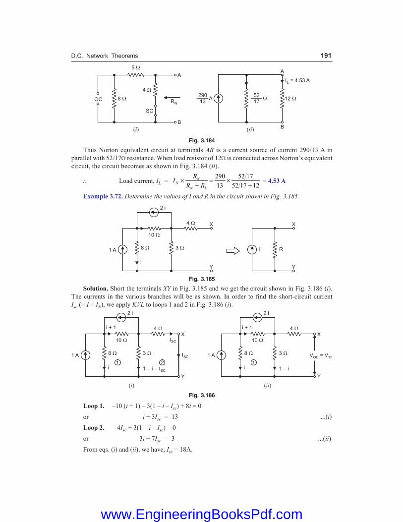
D.C. Network Theorems 191
Fig. 3.184
Thus Norton equivalent circuit at terminals AB is a current source of current 290/13 A in parallel with 52/17Ω resistance. When load resistor of 12Ω is connected across Norton’s equivalent circuit, the circuit becomes as shown in Fig. 3.184 (ii).
∴ Load current, IL = 290 52 17
13 52 17 12N
NN L
RIR R
× = ×+ +
= 4.53 A
Example 3.72. Determine the values of I and R in the circuit shown in Fig. 3.185.
Fig. 3.185
Solution. Short the terminals XY in Fig. 3.185 and we get the circuit shown in Fig. 3.186 (i). The currents in the various branches will be as shown. In order to find the short-circuit current Isc (= I = IN), we apply KVL to loops 1 and 2 in Fig. 3.186 (i).
Fig. 3.186
Loop 1. –10 (i + 1) – 3(1 – i – Isc) + 8i = 0
or i + 3Isc = 13 ...(i) Loop 2. – 4Isc + 3(1 – i – Isc) = 0
or 3i + 7Isc = 3 ...(ii) From eqs. (i) and (ii), we have, Isc = 18A.
www.EngineeringBooksPdf.com

192 Basic Electrical Engineering
In order to find the open-circuited voltage Voc (= VTh) at terminals X and Y, refer to Fig 3.186 (ii). The various branch currents are shown. Applying KVL to loop 1 in Fig. 3.186 (ii), we have,
–10 (i + 1) – 3(1 – i) + 8i = 0 or i = 13A
∴ Voc = Voltage across 3Ω resistor
= 3(1 – i) = 3(1 – 13) = – 36 V
Thevenin resistance, R(= RN) = oc
sc
VI
= 36
18 = 2Ω
Current I = IN = – 18A
Note the polarity of current source I (= IN). Example 3.73. With the help of Norton’s theorem, find Vo in the circuit shown in Fig. 3.187 (i). All resistances are in ohms.
Fig. 3.187
Solution. In order to find Vo, it is profitable to find Norton equivalent circuit to the left of terminals 1 – 1′ and to the right of terminals 2 – 2′ in Fig. 3.187 (i). To the left of terminals 1 – 1′, Voc = 15 × 1 = 15 V and RN = 1 + 1 = 2Ω so that IN = 15/2 = 7.5A as shown in Fig. 3.187 (ii). To the right of terminals 2 – 2′, Voc = 10 V and RTh = RN = 4Ω so that IN = 10/4 = 2.5A as shown in Fig. 3.187 (iii). The two Norton equivalent circuits are put back at terminals 1 – 1′, and 2 – 2′ as shown in Fig. 3.187 (iv).
Fig. 3.187
In Fig. 3.187 (iv), the two current sources, being parallel and carrying currents in the same direction, can be combined into a single current source of 7.5 + 2.5 = 10A. The three resistances are in parallel and can be combined to give a single resistance = 2Ω || 4Ω || 4Ω = 1Ω. Therefore, the circuit of Fig. 3.187 (iv) reduces to the circuit shown in Fig. 3.187 (v). ∴ Vo = 10A × 1Ω = 10V
www.EngineeringBooksPdf.com

D.C. Network Theorems 193
Example 3.74. Find current in the 4 ohm resistor by any three methods for the circuit shown in Fig. 3.188(i).
Fig. 3.188 Solution. Method 1. We shall find current in 4Ω resistor by mesh current method. Mark three mesh currents i1, i2 and i3 in the three loops as shown in Fig. 3.188 (ii). The describing circuit equations are : i1 = 5A due to the current source of 5A VA – VB = 6V due to voltage source of 6V i3 – i2 = 2A due to current source of 2A
VA = (i1 – i2)2 ; VB = i3 × 4 Now, – 6 – 4i3 – 2 (i2 – i1) = 0 ... Applying KVL or – 6 – 4 (2 + i2) – 2 (i2 – 5) = 0 or – 6i2 = 4
∴ i2 = 4 2
A6 3
− = − and i3 = i2 + 2 = 2 4
2 A3 3
− + =
∴ Current in 4Ω resistor = i3 = 4 A3
Method 2. We now find current in 4Ω resistor by Thevenin’s theorem. Remove 4Ω resistor (i.e. load) and the circuit becomes as shown in Fig. 3.188 (iii). Current in 2Ω resistor = 5 + 2 = 7A It is because 6V source is ineffective in producing any current. In going from point X to point Y via B and A, we have, VX + 6 – 7 × 2 = VY
or VX – VY = 7 × 2 – 6 = 8V ∴ VTh = VXY = VX – VY = 8V In order to find RTh, short circuit the voltage source and open-circuit the current sources in Fig. 3.188 (iii). Then circuit becomes as shown in Fig. 3.188 (iv). The resistance at the open-circuited terminals XY in Fig. 3.188 (iv) is RTh. ∴ RTh = 2Ω
∴ Current in 4Ω resistor = 4
Th
Th
VR +
= 8
2 4+ =
4 A3
Fig. 3.188
www.EngineeringBooksPdf.com

194 Basic Electrical Engineering
Method 3. Finally, we find current in 4Ω resistor by Norton’s theorem. To find IN, short-circuit 4Ω resistor in Fig. 3.188 (i). The circuit then becomes as shown in Fig. 3.188 (v). The current distribution in the various branches will be as shown.
Fig. 3.188
It is clear from Fig. 3.188 (v) that :
IN = 2 + 2 = 4A
RN = RTh = 2Ω ...as calculated above
When 4Ω resistor is connected to Norton equivalent circuit, it becomes as shown in Fig. 3.188 (vi). ∴ Current in 4Ω resistor is given by (current-divider rule) ;
I = 2
42 4
×+
= 8
6 = 4 A
3 Example 3.75. Using Norton’s theorem, find current through 1Ω resistor in Fig. 3.189 (i). All resistances are in ohms,
Fig. 3.189
Solution. To find the answers, we convert the three voltage sources into their equivalent current sources.
(a) 12 V source in series with (4 + 2) = 6Ω resistance is converted into equivalent current source of 12V/6Ω = 2A in parallel with 6Ω resistance.
(b) 6V source in series with 6Ω resistance is converted into equivalent current source of 6V/6Ω = 1A in parallel with 6Ω resistance.
(c) 24V source in series with 12Ω resistance is converted into equivalent current source of 24V/12Ω = 2A in parallel with 12Ω resistance.
After the above source conversions, the circuit of Fig. 3.189 (i) becomes the circuit shown in Fig. 3.189 (ii).
www.EngineeringBooksPdf.com
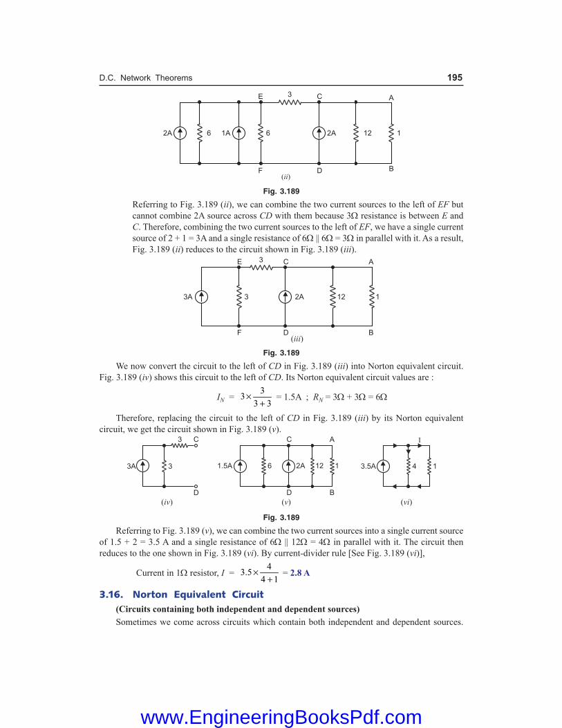
D.C. Network Theorems 195
Fig. 3.189
Referring to Fig. 3.189 (ii), we can combine the two current sources to the left of EF but cannot combine 2A source across CD with them because 3Ω resistance is between E and C. Therefore, combining the two current sources to the left of EF, we have a single current source of 2 + 1 = 3A and a single resistance of 6Ω || 6Ω = 3Ω in parallel with it. As a result, Fig. 3.189 (ii) reduces to the circuit shown in Fig. 3.189 (iii).
Fig. 3.189
We now convert the circuit to the left of CD in Fig. 3.189 (iii) into Norton equivalent circuit. Fig. 3.189 (iv) shows this circuit to the left of CD. Its Norton equivalent circuit values are :
IN = 3
33 3
×+
= 1.5A ; RN = 3Ω + 3Ω = 6Ω
Therefore, replacing the circuit to the left of CD in Fig. 3.189 (iii) by its Norton equivalent circuit, we get the circuit shown in Fig. 3.189 (v).
Fig. 3.189
Referring to Fig. 3.189 (v), we can combine the two current sources into a single current source of 1.5 + 2 = 3.5 A and a single resistance of 6Ω || 12Ω = 4Ω in parallel with it. The circuit then reduces to the one shown in Fig. 3.189 (vi). By current-divider rule [See Fig. 3.189 (vi)],
Current in 1Ω resistor, I = 4
3.54 1
×+
= 2.8 A
3.16. Norton Equivalent Circuit (Circuits containing both independent and dependent sources) Sometimes we come across circuits which contain both independent and dependent sources.
www.EngineeringBooksPdf.com

196 Basic Electrical Engineering
One such example is shown in Fig. 3.190. The procedure for finding Norton equivalent circuit (i.e. finding iN and RN) in such cases is as under :
Fig. 3.190
(i) The open-circuited voltage voc(= vTh) at terminals ab is determined as usual with sources present.
(ii) We cannot find RN (= RTh) at terminals ab simply by calculating equivalent resistance because of the presence of the dependent source. Instead, we place a short circuit across the terminals ab and find the value of short-circuit current isc (= iN) at terminals ab.
(iii) Norton resistance, RN = voc/isc (= vTh/isc). Note. In case the circuit contains dependent sources only, the procedure for finding voc (= vTh) and
RN(= RTh) is as under : (a) In this case, voc = 0 and isc = 0 because no independent source is present. (b) We cannot use the relation RN = voc/isc as we do in case the circuit contains both independent and
dependent sources. (c) In order to find RN, we excite the circuit at terminals ab by connecting 1A source to the terminals a
and b and calculate the value of vab. Then RN (= RTh) = vab/1Ω.
Example 3.76. Find the values of iN and RN at terminals ab for the circuit shown in Fig. 3.191 (i). Solution. We first put a short circuit across terminals a and b to find short-circuit current isc (= iN) at terminals ab as shown in Fig. 3.191 (ii). Applying KCL at node c, we have, 10 = i1 + i2 + isc or i2 = 10 – i1 – isc Applying KVL to loops 1 and 2, we have, – 4i2 + 6i1 – 2i1 = 0 ... Loop 1 or – 4(10 – i1 – isc) + 4i1 = 0 ...(i) Also –6i1 + 3isc = 0 ...(ii) ... Loop 2 From eqs. (i) and (ii), isc = iN = 5A.
Fig. 3.191 In order to find voc (= vTh), we refer to Fig. 3.191 (iii) where we have, voc = 6i1 ...(iii)
Fig. 3.191
www.EngineeringBooksPdf.com

D.C. Network Theorems 197
Applying KVL to the central loop in Fig. 3.191 (iii), – 4 (10 – i1) + 6i1 – 2i1 = 0 ...(iv) From eqs. (iii) and (iv), we have, voc = vTh = 30V.
Also RN (= RTh) = oc
sc
vi
= 30
5 = 6Ω
Tutorial Problems 1. Using Norton’s theorem, find the current in 8 Ω resistor of the network shown in Fig. 3.192. [1.55 A]
Fig. 3.192 Fig. 3.193 2. Using Norton’s theorem, find the current in the branch AB containing 6 Ω resistor of the network shown
in Fig. 3.193. [0.466 A] 3. Show that when Thevenin’s equivalent circuit of a network is converted into Norton equivalent circuit,
IN = VTh/RTh and RN = RTh. 4. Find the voltage between points A and B in the network shown in Fig. 3.194 using Norton’s theorem. [2·56 V]
Fig. 3.194 Fig. 3.195 5. The ammeter labelled A in Fig. 3.195 reads 35 mA. Is the 2·2 kΩ resistor shorted ? Assume that ammeter
has zero resistance. [Shorted] 6. Find Norton equivalent circuit to the left of terminals a – b in Fig. 3.196. [IN = 1·5 A; RN = 4 Ω]
Fig. 3.196 Fig. 3.197
www.EngineeringBooksPdf.com

198 Basic Electrical Engineering
7. What is the current in the 100 Ω resistor in Fig. 3.197 if the 990 Ω resistor is changed to 1010 Ω ? Use Norton theorem to obtain the result. [13·45 µA]
8. Determine the Norton equivalent circuit and the load current in RL in Fig. 3.198. The various circuit values are :
E ′ = 64 V ; R1 = 230 Ω ; R2 = 450 Ω ; R3 = 260 Ω ; R4 = 550 Ω ; R5 = 440 Ω ; RL = 360 Ω
Fig. 3.198 Fig. 3.199
9. In Fig. 3.199, replace the network to the left of terminals ab with its Norton equivalent.
[IN = 2 A+ 12.5
RR
; RN = 50 + 625
+ 25R
RΩ ]
10. When any source (voltage or current) is delivering maximum power to a load, prove that overall circuit efficiency is 50%.
3.17. Maximum Power Transfer Theorem This theorem deals with transfer of maximum power from a source to load and may be stated as under : In d.c. circuits, maximum power is transferred from a source to load when the load resistance is made equal to the internal resistance of the source as viewed from the load terminals with load removed and all e.m.f. sources replaced by their internal resistances.
Fig. 3.200
Fig. 3.200 (i) shows a circuit supplying power to a load RL. The circuit enclosed in the box can be replaced by Thevenin’s equivalent circuit consisting of Thevenin voltage V = VTh in series with Thevenin resistance Ri(=RTh) as shown in Fig. 3.200 (ii). Clearly, resistance Ri is the resistance measured between terminals AB with RL removed and e.m.f. sources replaced by their internal resistances. According to maximum power transfer theorem, maximum power will be transferred from the circuit to the load when RL is made equal to Ri, the Thevenin resistance at terminals AB.
3.18. Proof of Maximum Power Transfer Theorem Consider a voltage source V of internal resistance Ri delivering power to a load RL. We shall prove that when RL = Ri, the power delivered to RL is maximum. Referring to Fig. 3.201 (i), we have,
Circuit current, I = L i
VR R+
Power delivered to load, P = I2 RL
www.EngineeringBooksPdf.com

D.C. Network Theorems 199
= 2
LL i
V RR R
+
...(i)
For a given source, generated voltage V and internal resistance Ri are constant. Therefore, power delivered to the load depends upon RL. In order to find the value of RL for which the value of P is maximum, differentiate eq. (i) w.r.t. RL and set the result equal to zero.
Fig. 3.201
Thus, L
dPdR
= 2
24
( ) 2 ( )
( )L i L L i
L i
R R R R RVR R
+ − + +
= 0
or (RL + Ri)2 − 2 RL (RL + Ri) = 0
or (RL + Ri) (RL + Ri − 2RL) = 0 or (RL + Ri) (Ri − RL) = 0 Since RL + Ri cannot be zero, ∴ Ri − RL = 0 or RL = Ri or Load resistance = Internal resistance of the source Thus, for maximum power transfer, load resistance RL must be equal to the internal resistance Ri of the source. Fig. 3.201 (ii) shows the graph between power delivered (P) and RL. We may extend the maximum power transfer theorem to a linear circuit rather than a single source by means of Thevenin’s theorem as under : The maximum power is obtained from a linear circuit at a given pair of terminals when ter-minals are loaded by Thevenin’s resistance (RTh) of the circuit. The above statement is obviously true because by Thevenin’s theorem, the circuit is equivalent to a voltage source in series with internal resistance (RTh) of the circuit. Important Points. The following points are worth noting about maximum power transfer theorem : (i) The circuit efficiency at maximum power transfer is only 50% as one-half of the total
power generated is dissipated in the internal resistance Ri of the source.
Efficiency = 2
2
Output power
Input power ( )L
L i
I RI R R
=+
= 1
2 2L
L
RR
= = 50% ( RL = Ri)
(ii) Under the conditions of maximum power transfer, the load voltage is one-half of the open-circuited voltage at the load terminals.
www.EngineeringBooksPdf.com

200 Basic Electrical Engineering
Load voltage = I RL = 2 2
LL
L i L
V RV VRR R R
= = +
(iii) Max. power transferred = 2 2 2
2 4L LL i L L
V V VR RR R R R
= = + Note. In case of a practical current source, the maximum power delivered is given by ;
Pmax = 2
4N NI R
where IN = Norton current RN = Norton resistance (= RTh = Ri)
3.19. Applications of Maximum Power Transfer Theorem This theorem is very useful in situations where transfer of maximum power is desirable. Two important applications are listed below : (i) In communication circuits, maximum power transfer is usually desirable. For instance, in a
public address system, the circuit is adjusted for maximum power transfer by making load (i.e. speaker) resistance equal to source (i.e. amplifier) resistance. When source and load have the same resistance, they are said to be matched.
In most practical situations, the internal resistance of the source is fixed. Also, the device that acts as a load has fixed resistance. In order to make RL = Ri, we use a transformer. We can use the reflected-resistance characteristic of the transformer to make the load resistance appear to have the same value as the source resistance, thereby ‘‘fooling’’ the source into ‘‘thinking’’ that there is a match (i.e. RL = Ri). This technique is called impedance matching.
(ii) Another example of maximum power transfer is found in starting of a car engine. The power delivered to the starter motor of the car will depend upon the effective resistance of the motor and internal resistance of the battery. If the two resistances are equal (as is the case when battery is fully charged), maximum power will be transferred to the motor to turn on the engine. This is particularly desirable in winter when every watt that can be extracted from the battery is needed by the starter motor to turn on the cold engine. If the battery is weak, its internal resistance is high and the car does not start.
Note. Electric power systems are never operated for maximum power transfer because the efficiency under this condition is only 50%. This means that 50% of the generated power will be lost in the power lines. This situation cannot be tolerated because power lines must operate at much higher than 50% efficiency.
Example 3.77. Two identical cells connected in series deliver a maximum power of 1W to a resistance of 4 Ω. What is the internal resistance and e.m.f. of each cell ? Solution. Let E and r be the e.m.f. and internal resistance of each cell. The total internal resistance of the battery is 2r. For maximum power transfer, 2 r = RL = 4 ∴ r = RL/2 = 4/2 = 2 Ω
Maximum power = 2*(2 )
4 L
ER
or 1 = 24
4 L
ER
∴ E = LR = 4 = 2 V
* Here total voltage = 2E.
www.EngineeringBooksPdf.com

D.C. Network Theorems 201
Example 3.78. Find the value of resistance R to have maximum power transfer in the circuit shown in Fig. 3.202 (i). Also obtain the amount of maximum power. All resistances are in ohms.
Fig. 3.202
Solution. To find the desired answers, we should find VTh and RTh at the load (i.e. R) terminals. For this purpose, we first convert 120V voltage source in series with 10Ω resistance into equivalent current source of 120/10 = 12A in parallel with 10Ω resistance. The circuit then becomes as shown in Fig. 3.202. (ii).
Fig. 3.202
To find VTh, remove R (i.e. load) from the circuit in Fig. 3.202 (ii), and the circuit becomes as shown in Fig. 3.202 (iii). Then voltage across the open-circuited terminals AB is VTh. Referring to Fig. 3.202 (iii) and applying KCL, we have,
10 5
Th ThV V+ = 12 + 6 or VTh = 60V
In order to find RTh, remove R and replace the current sources by open in Fig. 3.202 (ii). Then circuit becomes as shown in Fig. 3.202 (iv). Then resistance at the open-circuited terminals AB is RTh. ∴ RTh = 10Ω || 5Ω =
10 5
10 5
×+
= 10
3Ω
When R is connected to the terminals of Thevenin equivalent circuit, the circuit becomes as shown in Fig. 3.202 (v). For maximum power transfer, the condition is
R = RTh = 103
Ω
Max. power transferred, Pmax = 2
4Th
L
VR
= 2 2(60)
4 4 (10 3)ThVR
=×
= 270 W
www.EngineeringBooksPdf.com

202 Basic Electrical Engineering
Example 3.79. Calculate the value of R which will absorb maximum power from the circuit of Fig. 3.203 (i). Also find the value of maximum power.
Fig. 3.203
Solution. To find the desired answers, we should find VTh and RTh at the load (i.e. R) terminals. For this purpose, we first convert 2A current source in parallel with 15Ω resistance into equivalent voltage source of 2A × 15Ω = 30 V in series with 15Ω resistance. The circuit then becomes as shown in Fig. 3.203 (ii).
Fig. 3.203
To find VTh, remove R (i.e. load) from the circuit in Fig. 3.203 (ii) and the circuit becomes as shown in Fig. 3.203 (iii). Then voltage across the open-circuited terminals AB is VTh. Referring to Fig. 3.203 (iii), Current in 3Ω resistor, I =
30 6
15 6 3
−+ +
= 1A
In Fig. 3.203 (iii), as we go from point A to point B via 3Ω resistor, we have, VA – I × 3 – 8 = VB
or VA – VB = I × 3 + 8 = 1 × 3 + 8 = 11V ∴ VTh = VAB = VA – VB = 11V In order to find RTh, remove R and replace the voltage sources by short in Fig. 3.203 (ii). Then circuit becomes as shown in Fig. 3.203 (iv). Then resistance at open-circuited terminals AB is RTh.
∴ RTh = (15 + 6)Ω || 3Ω = 21 3
21 3
×+
= 21
8Ω
For maximum power transfer, the condition is
R = RTh = 218
Ω
Max. power transferred, Pmax = 2
4Th
L
VR
= 2
4ThVR
= 2(11)
4 (21 8)× = 11.524 W
www.EngineeringBooksPdf.com

D.C. Network Theorems 203
Example 3.80. Determine the value of RL in Fig. 3.204 (i) for maximum power transfer and evaluate this power. Solution. The three current sources in Fig. 3.204 (i) are in parallel and supply current in the same direction. Therefore, they can be replaced by a single current source supplying 0·8 + 1 + 0·9 = 2·7 A as shown in Fig. 3.204 (ii). The circuit to the left of RL in Fig. 3.204 (ii) can be replaced by Thevenin’s equivalent circuit as under :
Fig. 3.204
VTh = IN RN = 2·7 × 100 = 270 V
Ri = RN = 100 Ω The Thevenin’s equivalent circuit to the left of RL is VTh(= 270 V) in series with Ri (= 100 Ω). When load RL is connected, the circuit becomes as shown in Fig. 3.205. It is clear that maximum power will be transferred when RL = Ri = 100 Ω
Max. power = 2 2(270)
4 4 100Th
L
VR
=×
= 182·25 watts Example 3.81. Determine the maximum power that can be delivered by the circuit shown in Fig. 3.206 (i). Solution. Fig. 3.206 (ii) shows the Norton’s equivalent circuit. Maximum power transfer occurs when RL = RN = 300 Ω.
Fig. 3.206
Referring to Fig. 3.206 (ii), current in RL (= 300 Ω) = IN/2 = 0·5/2 = 0·25 A ∴ Max. power transferred = (0·25)2 × RL = (0·25)2 × 300 = 18·8 W Example 3.82. What percentage of maximum possible power is delivered to RL in Fig. 3.207 (i) when RL = 2 RTh ? Solution. Fig. 3.207 (ii) shows the circuit when RL = 2 RTh.
Circuit current = 2 3
Th Th
Th Th Th
V VR R R
=+
Fig. 3.205
www.EngineeringBooksPdf.com

204 Basic Electrical Engineering
Voltage across load, VL = 2
23 3
ThTh Th
Th
V R VR
× =
Fig. 3.207
Power delivered to load, PL =
2
222
432 18
ThThL
L Th Th
V VVR R R
= =
Since Pmax = VTh2 /4 RTh, the ratio of PL/Pmax is
L
max
PP
=
2
2
4
18
4
Th
Th
Th
Th
VR
VR
= 16
18
∴ PL = 16100
18 maxP × = 88·89% of Pmax
Example 3.83. Find the maximum power in RL which is variable in the circuit shown in Fig. 3.208 (i). Solution. We shall use Thevenin theorem to obtain the result. For this purpose, remove the load RL as shown in Fig. 3.208 (ii). The open-circuited voltage at terminals AB in Fig. 3.208 (ii) is equal to VTh. It is clear from Fig. 3.208 (ii) that current in the branch containing 40 Ω and 60 Ω resistors is 1 A. Similarly, current in the branch containing two 50 Ω resistors is 1 A. It is clear that point A is at higher potential than point B. Applying KVL to the loop EABCDE, we have, – 40 × 1 – VAB – 2 + 50 × 1 = 0 ∴ VAB = 8 V
Now VAB in Fig. 3.208 (ii) is equal to VTh. Therefore, VTh = 8 V.
Fig. 3.208 In order to find Thevenin’s resistance RTh, replace 100V and 2V batteries by a short in Fig. 3.208 (ii). Then resistance at terminals AB is the RTh. It is clear that 40 Ω and 60 Ω resistors are in parallel and so the two 50 Ω resistors.
www.EngineeringBooksPdf.com

D.C. Network Theorems 205
∴ RTh = (40 || 60) + (50 || 50) = 40 60 50 50
40 60 50 50
× ×++ +
= 24 + 25 = 49 Ω
Therefore, for maximum power, RL should be 49 Ω. The Thevenin equivalent circuit is a voltage source of 8 V in series with a resistance of 49 Ω. When load RL is connected across the terminals of Thevenin equivalent circuit, the total circuit resistance = 49 + 49 = 98 Ω.
∴ Circuit current, I = 8 8
49 49 98Th
Th L
VR R
= =+ +
= 0·08163 A
∴ Pmax = I2RL = (0·08163)2 × 49 = 0·3265 W Example 3.84. For the circuit shown in Fig. 3.209 (i), find the value of R that will receieve maximum power. Determine this power.
Fig. 3.209
Solution. We will use Thevenin’s theorem to obtain the results. In order to find VTh, remove the variable load R as shown in Fig. 3.209 (ii). Then open-circuited voltage across terminals AB is equal to VTh. Current in branch DAC =
100
7.1 5.2+ = 8·13 A
Current in branch DBC = 100
19.6 10.9+ = 3·28 A
It is clear from Fig. 3.209 (ii) that point A is at higher* potential than point B. Applying KVL to the loop A′ACBB′A′, we have, – 5·2 × 8·13 + 10· 9 × 3·28 + VAB = 0 ∴ VAB = 6·52 V Now VAB in Fig. 3.209 (ii) is equal to VTh so that VTh = 6·52 V. In order to find RTh, replace the 100 V source in Fig. 3.209 (ii) by a short. The circuit becomes as shown in Fig. 3.209 (iii). The resistance across terminals AB is the Thevenin resistance. Referring to Fig. 3.209 (iii), RAB = RTh = (5·2 | | 7·1) + (10·9 | | 19·6) = 3 + 7 = 10 Ω
Therefore, for maximum power transfer, R = RTh = 10 Ω.
Pmax = 2 2( ) (6.52)
4 4 10ThVR
=×
= 1·06 W
* The fall in potential along DA is less than the fall in potential along DB. Since point D is common, point A will be at higher potential than point B.
Fig. 3.209
www.EngineeringBooksPdf.com

206 Basic Electrical Engineering
Example 3.85. For the circuit shown in Fig. 3.210 (i), what will be the value of RL to get maximum power? Also find this power. Solution. We shall use Thevenin’s theorem to obtain the results. In order to find VTh, remove the load RL as shown in Fig. 3.210 (ii). Then voltage at the open-circuited terminals AB is equal to VTh i.e. VAB = VTh. The total load on 10 V source is RT = (90 || 60 || 180) + 20 = 30 + 20 = 50 Ω
Fig. 3.210 Current supplied by source, I = 10/50 = 0·2 A ∴ VAB = VTh = 10 – 20 × 0·2 = 6V In order to find RTh, replace the 10 V source by a short in Fig. 3.210 (ii). Then, RTh = 20 || 90 || 60 || 180 = 12 Ω Therefore, the variable load RL will receive maximum power when RL = RTh = 12 Ω.
∴ Pmax = 2 2( ) (6)
4 4 12Th
L
VR
=×
= 0·75 W
Tutorial Problems 1. Find the value of RL in Fig. 3.211 necessary to obtain maximum power in RL. Also find the maximum
power in RL. [150Ω ; 1.042 W]
Fig. 3.211 Fig. 3.212 2. If RL in Fig. 3.211 is fixed at 100 Ω, what alternation (s) can be made in the rest of the circuit to obtain
maximum power in RL ? [Short out 50 Ω resistor] 3. What percentage of the maximum possible power is delivered to RL in Fig. 3.212, when
RL = RTh/2 ? [88.9%] 4. Determine the value of RL for maximum power transfer in Fig. 3.213 and evaluate this power.
[100 Ω; 182·25 W]
Fig. 3.213 Fig. 3.214
www.EngineeringBooksPdf.com

D.C. Network Theorems 207
5. What value should RL be in Fig. 3.214 to achieve maximum power transfer to the load? [588 Ω] 6. For the circuit shown in Fig. 3.215, find the value of RL for which power transferred is maximum. Also
calculate this power. [50 Ω; 0·72 W]
Fig. 3.215 Fig. 3.216 7. Calculate the value of RL for transference of maximum power in Fig. 3.216. Evaluate this power.
[220 Ω; 2·2 W]
3.20. Reciprocity Theorem This theorem permits us to transfer source from one position in the circuit to another and may be stated as under : In any linear, bilateral network, if an e.m.f. E acting in a branch X causes a current I in branch Y, then the same e.m.f. E located in branch Y will cause a current I in branch X. However, currents in other parts of the network will not remain the same. Explanation. Consider the circuit shown in Fig. 3.217 (i). The e.m.f. E (=100 V) acting in the branch FAC produces a current I amperes in branch CDF and is indicated by the ammeter. According to reciprocity theorem, if the e.m.f. E and ammeter are interchanged* as shown in Fig. 3.217 (ii), then the ammeter reading does not change i.e. the ammeter now connected in branch FAC will read I amperes. In fact, the essence of this theorem is that E and I are interchangeable. The ratio E/I is constant and is called transfer resistance (or impedance in case of a.c. system).
Fig. 3.217 Note. Suppose an ideal current source is connected across points ab of a network and this causes a voltage v to appear across points cd of the network. The reciprocity theorem states that if the current source is now connected across cd, the same amount of voltage v will appear across ab. This is sometimes stated as follows: An ideal current source and an ideal voltmeter can be interchanged without changing the reading of the voltmeter. However, voltages in other parts of the network will not remain the same. Example 3.86. Verify the reciprocity theorem for the network shown in Fig. 3.217 (i). Also find the transfer resistance. Solution. In Fig. 3.217 (i), e.m.f. E ( = 100V) is in branch FAC and ammeter is in branch CDF. Referring to Fig. 3.217 (i),* If the source of e.m.f in the original circuit has an internal resistance, this resistance must remain in the
original branch and cannot be transferred to the new location of the e.m.f.
www.EngineeringBooksPdf.com

208 Basic Electrical Engineering
Resistance between C and F = 20 Ω || (8 + 8) Ω = 20 × 16/36 = 8·89 Ω Total circuit resistance = 20 + 8·89 = 28·89 Ω ∴ Current supplied by battery = 100/28·89 = 3·46 A The battery current is divided into two parallel paths viz. path CF of 20 Ω and path CDF of 8 + 8 = 16Ω. Current in branch CDF, I = 3·46 × 20/36 = 1·923 A Now in Fig. 3.217 (ii), E and ammeter are interchanged. Referring to Fig. 3.217 (ii), Resistance between C and F = 20 × 20/40 = 10 Ω Total circuit resistance = 10 + 8 + 8 = 26 Ω Current supplied by battery = 100/26 = 3·846 A The battery current is divided into two parallel paths of 20 Ω each. ∴ Current in branch CAF = 3·846/2 = 1·923A Hence, ammeter reading in both cases is the same. This verifies the reciprocity theorem. Transfer resistance = E/I = 100/1·923 = 52 Ω Example 3.87. Find the currents in the various branches of the circuit shown in Fig. 3.218 (i). If a battery of 9V is added in branch BCD, find current in 4 Ω resistor using reciprocity theorem and superposition theorem.
Fig. 3.218
Solution. Referring to Fig. 3.218 (i), we have, Total resistance to source = 4 Ω + [6 Ω || (1 + 2) Ω] = 4 + 6 × 3/9 = 6 Ω Current supplied by source (i.e. current in 4 Ω resistor or branch DAB) = 18/6 = 3 A Current in branch BD = 3 × 3/9 = 1 A Current in branch BCD = 3 × 6/9 = 2 A In Fig. 3.218 (i), the current in branch BCD due to 18 V source acting alone is 2 A. If the 18V source is placed in branch BCD, then according to reciprocity theorem, the current in 4 Ω will be 2 A flowing from B to A. If a battery of 9 V is placed in branch BCD, then current in 4 Ω resistor due to it alone would be 2 × 9/18 = 1 A (By proportion). Now referring to Fig. 3.218 (ii), the current in 4 Ω due to 18 V battery alone is 3 A flowing from A to B. The current in 4 Ω resistor due to 9 V acting alone in branch BCD is 1 A flowing from B to A. By superposition theorem, the current in 4 Ω is the algebraic sum of the two currents i.e. Current in 4 Ω = 3 − 1 = 2 A from A to B
www.EngineeringBooksPdf.com

D.C. Network Theorems 209
Example 3.88. Prove the reciprocity theorem. Solution. We now prove the reciprocity theorem for the circuit shown in Fig. 3.219. In Fig. 3.219 (i), the e.m.f. E is acting in the branch FAC and the current in the branch CDF is I2. If the same e.m.f. E now acts in branch CDF [See Fig. 3.219 (ii)], then current Ib in the branch FAC will be equal to I2. We now show that Ib = I2. Referring to Fig. 3.219 (i), we have,
Fig. 3.219
E = I1 RT
where RT = R1 + (R2 || R3) = 2 31
2 3
R RRR R
+ +
∴ E = 2 31 1
2 3
R RI RR R
+ +
= 1 2 2 3 3 11
2 3
R R R R R RIR R
+ + +
...(i)
Also in Fig. 3.219 (i), 0 = – (I1 – I2) R3 + I2 R2
or I2 = 31
2 3
RIR R
+
...(ii)
Dividing eq. (i) by eq. (ii), we have,
2
EI
= 1 2 2 3 3 1
3
R R R R R RR
+ + ...(iii)
Similarly, it can be shown that in Fig. 3.219 (ii), we have,
b
EI
= 1 2 2 3 3 1
3
R R R R R RR
+ + ...(iv)
From eqs. (iii) and (iv), Ib = I2
Therefore, reciprocity theorem stands proved.
3.21. Millman’s Theorem Millman’s theorem is a combination of Thevenin’s and Norton’s theorems. It is used to reduce any number of parallel voltage/current sources to an equivalent circuit containing only one source. It has the advantage of being easier to apply to some networks than mesh analysis, nodal analysis or superposition. This theorem can be stated in terms of voltage sources or current sources or both. 1. Parallel voltage sources. Millman’s theorem provides a method of calculating the common voltage across different parallel-connected voltage sources and may be stated as under : The voltage sources that are directly connected in parallel can be replaced by a single equivalent voltage source.
www.EngineeringBooksPdf.com

210 Basic Electrical Engineering
Obviously, the above statement is true by virtue of Thevenin’s theorem. Fig 3.220 (i) shows three parallel-connected voltage sources E1, E2 and E3. Then common terminal voltage VAB of these parallel voltage sources is given by ;
VAB = 1 1 2 2 3 3
1 2 31 1 1E R E R E R
R R R+ ++ + = 1 2 3
1 2 3
I I I IG G G G
+ + Σ=+ + Σ
...(i)
Fig. 3.220
This voltage represents the Thevenin’s voltage VTh. The denominator represents Thevenin’s resistance RTh i.e.
RTh = 1 2 3
1
1 1 1R R R+ +
Therefore, parallel-connected voltage sources in Fig 3.220 (i) can be replaced by a single voltage source as shown in Fig 3.220 (ii). If load RL is connected across terminals AB, then load current IL is given by ;
IL = Th
Th L
VR R+
Note. If a branch does not contain any voltage source, the same procedure is used except that current in that branch will be zero. This is illustrated in example 3.89. 2. Parallel current sources. The Millman’s theorem states as under : The current sources that are directly connected in parallel can be replaced by a single equivalent current source. The current of this single current source is the algebraic sum of the individual source currents. The internal resistance of the single current source is equal to the combined resistance of the parallel combination of the source resistances.
Fig. 3.221
Fig. 3.221 (i) shows three parallel connected current sources. The resultant current of the three sources is 0·3 ↓ + 0·6 ↑ + 0·8 ↓ = 0·5 A ↓
The internal resistance of the single current source is equal to the equivalent resistance of three parallel resistors.
www.EngineeringBooksPdf.com

D.C. Network Theorems 211
400 || 200 || 400 = 100 Ω
Thus the single equivalent current source has value 0·5 A and internal resistance 100 Ω in parallel as shown in Fig. 3.221 (ii). 3. Voltage sources and current sources in parallel. The Millman’s theorem is also applicable if the circuit has a mixture of parallel voltage and current sources. Each parallel-connected voltage source is converted to an equivalent current source. The result is a set of parallel-connected current sources and we can replace them by a single equivalent current source. Alternatively, each parallel-connected current source can be converted to an equivalent voltage source and the set of parallel-connected voltage sources can be replaced by an equivalent voltage source.
Example 3.89. Using Millman’s theorem, determine the common voltage Vxy and the load current in the circuit shown in Fig. 3.222 (i).
Fig. 3.222
Solution. Vxy = VTh = 1 1 2 2 3 3
1 2 31 1 1
E R E R E RR R R
+ ++ +
= 12 6 0 2 16 4 2 0 4 6
1 6 1 12 1 4 0.167 0.083 0.25 0.5
+ + + += =+ + + +
= 12V
RTh = 1
1 6 1 12 1 4+ + = 2Ω
Therefore, the circuit shown in Fig. 3.222 (i) can be replaced by the one shown in Fig. 3.222 (ii).
Load current = 12
2 20Th
Th L
VR R
=+ +
= 0.545 A
Example 3.90. Find the current in the 1 k Ω resistor in Fig. 3.223 by finding Millman equivalent voltage source with respect to terminals x – y. Solution. As shown Fig. 3.224 (i), each of the three voltage sources is converted to an equivalent current source. For example, the 36 V source in series with 18 kΩ resistor becomes a 36 V/18 kΩ = 2 mA current source in parallel with 18 kΩ. Note that the polarity of each current source is such that it produces current in the same direction as the voltage source it replaces.
The resultant current of the three current sources
= 2 mA ↑ + 3 mA ↑ + 2 mA ↓ = 3 mA ↑
Fig. 3.223
www.EngineeringBooksPdf.com

212 Basic Electrical Engineering
The parallel equivalent resistance of three resistors
= 18 kΩ || 9 kΩ || 3 kΩ = 2 kΩ
Fig. 3.224
Fig. 3.224 (ii) shows the single equivalent current source. Fig. 3.224 (iii) shows the voltage source that is equivalent to current source in Fig. 3.224 (ii). VTh = 3 mA × 2 kΩ = 6 V
Fig. 3.224
When the 1 kΩ resistor is connected across the x – y terminals, the current is
I = 6V
3kΩ = 2 mA
Example 3.91. Find an equivalent voltage source for the circuit shown in Fig. 3.225 (i). What is the load current?
Fig. 3.225
Solution. VAB = VTh = 1 1 2 2 3 3 4 4
1 2 3 41 1 1 1
E R E R E R E RR R R R+ + +
+ + +
= 10 10 *20 5 5 20 30 15 0.75
1 10 1 5 1 20 1 15 0.417
− + + −=+ + +
= – 1·8 V
Negative sign shows that terminal A is negative w.r.t. terminal B.* Note that polarity is opposite as compared to other sources.
www.EngineeringBooksPdf.com

D.C. Network Theorems 213
RTh = 1 2 3 4
1
1 1 1 1R R R R+ + +
= 1
1 10 1 5 1 20 1 15+ + + = 2.4Ω
Therefore, equivalent voltage source consists of 1·8 V source in series with 2·4 Ω resistor as shown in Fig. 3.225 (ii). ∴ Load current, IL =
1.8
2.4 5Th
Th L
VR R
=+ +
= 0.24A
Example 3.92. For the circuit shown in Fig. 3.225 (i) above, find the equivalent current source. Also find load current. Solution. Convert the voltage sources to current sources as shown in Fig. 3.226 (i). The arrow for each current source corresponds to the polarity of each voltage source in the original circuit.
Fig. 3.226 The equivalent current source is found by algebraically adding the currents of individual sources. Ieq = 1 A ↑ + 4 A ↓ + 0·25 A ↑ + 2 A ↑ = 0·75 A ↓ The downward arrow for Ieq shows that terminal A is negative w.r.t. terminal B.
Req = 10 Ω || 5 Ω || 20 Ω || 15 Ω = 2·4 Ω Therefore, the equivalent current source consists of 0·75 A current source in parallel with 2·4 Ω resistor as shown in Fig. 3.226 (ii). By current-divider rule, the load current IL is
IL = 2.4
0.752.4 5
×+
= 0.243A
Example 3.93. Find the load current for Fig. 3.227 (i) using the dual of Millman’s theorem.
Fig. 3.227 Solution. There is a dual for Millman’s theorem and it is useful for solving circuits with series current sources [See Fig. 3.227 (i)]. In such a case, the following equations are used to find the current and resistance of the equivalent circuit.
www.EngineeringBooksPdf.com

214 Basic Electrical Engineering
Ieq = 1 1 2 2 3 3
1 2 3
I R I R I RR R R
+ ++ +
Req = R1 + R2 + R3
Thus referring to Fig. 3.227 (i), we have,
Ieq = 0.1 100 0.5 150 1 50 15
A100 150 50 300
− × + × − × =+ +
= 50 mA
Req = 100 + 150 + 50 = 300 Ω The equivalent circuit is shown in Fig. 3.227 (ii). By current-divider rule, the load current IL is
IL = 300
50300 300
×+
= 25 mA
Example 3.94. By constructing a Millman equivalent voltage source with respect to terminals x – y, find the voltage across 40 Ω resistor in Fig. 3.228 (i).
Fig. 3.228
Solution. Note that 120 Ω and 180 Ω resistors are in a series path and can therefore be combined into an equivalent resistance of 300 Ω. The circuit is *redrawn as shown in Fig. 3.228 (ii). It is clear that redrawn circuit has three parallel-connected voltage sources. Referring to Fig. 3.228 (ii), we have, Vxy = VTh = 1 1 2 2 3 3
1 2 31 1 1
E R E R E RR R R
− ++ +
= 7.5 300 22.5 100 15 300
1 300 1 100 1 300
− ++ +
= 0.15
0.0167
− = – 9V
Negative sign shows that terminal x is negative w.r.t. terminal y.
RTh = 1 2 3
1 1
1 1 1 1 300 1 100 1 300R R R=
+ + + + = 60 Ω
Therefore, the equivalent voltage source consists of 9 V in series with 60 Ω resistor. When load is connected across the terminals of the equivalent voltage source, the circuit becomes as shown in Fig. 3.229. Load current, IL =
9
60 40Th
Th L
VR R
=+ +
= 0.09 A
Voltage across 40 Ω = IL RL = 0·09 × 40 = 3·6 V Note that Millman’s theorem is a powerful tool in the hands of engineers to solve many problems which cannot be solved easily by the usual methods of circuit analysis. Fig. 3.229
* It makes no difference on which side of each voltage source its series resistance is drawn.
www.EngineeringBooksPdf.com

D.C. Network Theorems 215
Tutorial Problems
1. Find the single equivalent current source for the circuit shown in Fig. 3.230.
Fig. 3.230 Fig. 3.231
2. By constructing a Millman equivalent voltage source at terminals x – y, find the voltage across R1 (= 5 Ω) in the circuit shown in Fig. 3.231. [4 V ± ]
3. Find the single equivalent current source for the circuit shown in Fig. 3.232.
Fig. 3.232
4. What is the current flowing in the load resistor in Fig. 3.233 ? [2·25 mA]
Fig. 3.233 Fig. 3.234
5. What is the drop and polarity of the load in Fig. 3.234 ? [ 8·13V and terminal A is negative]
3.22. Compensation Theorem It is sometimes necessary to know, when making a change in one branch of a network, what effect this change will have on the various currents and voltages throughout the network. The compensation theorem deals with this situation and may be stated for d.c. circuits as under : The compensation theorem states that any resistance R in a branch of a network in which current I is flowing can be replaced, for the purpose of calculations, by a voltage equal to – IR. It follows from Kirchhoff’s voltage law that the current I is unaltered if an e.m.f. – IR is substituted for the voltage drop IR.
www.EngineeringBooksPdf.com

216 Basic Electrical Engineering
Or If the resistance of any branch of a network is changed from R to (R + ∆R) where the current was originally I, then the change of current at any point in the network may be calculated by assuming than an e.m.f. – I∆R has been introduced into the modified branch while all other sources have their e.m.f.s. suppressed and are represented by their internal resistances only. Illustration. Let us illustrate the compensation theorem with a numerical example. Consider the circuit shown in Fig. 3.235 (i). The various branch currents in this circuit are :
I1 = 50
20 5+ = 2 A ; I2 = I3 = 1 A
Fig. 3.235
Now suppose that the resistance of the right branch is increased to 20 Ω i.e. ∆R = 20 – 10 = 10 Ω and a voltage V = – I3 ∆R = – 1 × 10 = – 10 V is introduced in this branch and voltage source replaced by a short ( internal resistance is assumed zero). The circuit becomes as shown in Fig. 3.235 (ii). The compensating currents produced by this voltage are also indicated. When these compensating currents are algebraically added to the original currents in their respective branches, the new branch currents will be as shown in Fig. 3.236. The compensation theorem is useful in bridge and potentiometer circuits, where a slight change in one resistance results in a shift from a null condition.
3.23. Delta/Star and Star/Delta Transformation There are some networks in which the resistances are neither in series nor in parallel. A familiar case is a three terminal network e.g. delta network or star network. In such situations, it is not possible to simplify the network by series and parallel circuit rules. However, converting delta network into star and vice-versa often simplifies the network and makes it possible to apply series-parallel circuit techniques.
3.24. Delta/Star Transformation Consider three resistors RAB, RBC and RCA connected in delta to three terminals A, B and C as shown in Fig. 3.237 (i). Let the equivalent star-connected network have resistances RA, RB and RC. Since the two arrangements are electrically equivalent, the resistance between any two terminals of one network is equal to the resistance between the corresponding terminals of the other network. Let us consider the terminals A and B of the two networks. Resistance between A and B for star = Resistance between A and B for deltaor RA + RB = RAB || (RBC + RCA)
or RA + RB = ( )
( )AB BC CA
AB BC CA
R R RR R R
++ +
...(i)
Fig. 3.236
www.EngineeringBooksPdf.com

D.C. Network Theorems 217
Fig. 3.237
Similarly, RB + RC = ( )BC CA AB
AB BC CA
R R RR R R
++ +
...(ii)
and RC + RA = ( )CA AB BC
AB BC CA
R R RR R R
++ +
...(iii)
Subtracting eq. (ii) from eq. (i) and adding the result to eq. (iii), we have,
RA = AB CA
AB BC CA
R RR R R+ +
...(iv)
Similarly, RB = BC AB
AB BC CA
R RR R R+ +
...(v)
and RC = CA BC
AB BC CA
R RR R R+ +
...(vi)
How to remember ? There is an easy way to remember these relations. Referring to Fig. 3.238, star-connected resistances RA, RB and RC are electrically equivalent to delta-connected resistances RAB, RBC and RCA. We have seen above that :
RA = AB CA
AB BC CA
R RR R R+ +
i.e. Any arm of star-connection = Product of two adjacent arms of
Sum of arms of
∆∆
Thus to find the star resistance that connects to terminal A, divide the product of the two delta resistors connected to A by the sum of the delta resistors. Same is true for terminals B and C.
3.25. Star/Delta Transformation Now let us consider how to replace the star-connected network of Fig. 3.237 (ii) by the equivalent delta-connected network of Fig. 3.237 (i). Dividing eq. (iv) by (v), we have,
RA/RB = RCA/RBC
∴ RCA = A BC
B
R RR
Dividing eq. (iv) by (vi), we have, RA / RC = RAB / RBC
Fig. 3.238
www.EngineeringBooksPdf.com

218 Basic Electrical Engineering
∴ RAB = A BC
C
R RR
Substituting the values of RCA and RAB in eq. (iv), we have,
RBC = B CB C
A
R RR RR
+ +
Similarly, RCA = C AC A
B
R RR RR
+ +
and RAB = A BA B
C
R RR RR
+ +
How to remember ? There is an easy way to remember these relations.
Referring to Fig. 3.239, star-connected resistances RA, RB and RC are electrically equivalent to delta-connected resistances RAB, RBC and RCA. We have seen above that :
RAB = A BA B
C
R RR RR
+ +
i.e. Resistance between two = Sum of star resistances connected to those terminals plus product of terminals of delta same two resistances divided by the third star resistance
Note. Figs. 3.240 (i) to (iii) show three ways that a wye (Y) arrangement might appear in a circuit. Because the wye-connected components may appear in the equivalent form shown in Fig. 3.240 (ii), the arrangement is also called a tee (T) arrangement. Figs. 3.240 (iv) to (vi) show equivalent delta forms. Because the delta (∆) arrangement may appear in the equivalent form shown in Fig. 3.240 (vi), it is also called a pi (π) arrangement. The figures show only a few of the ways the wye (Y) and delta (∆) networks might be drawn in a schematic diagram. Many equivalent forms can be drawn by rotating these basic arrangements through various angles. Note that each network has three terminals.
Fig. 3.240
Fig. 3.239
www.EngineeringBooksPdf.com

D.C. Network Theorems 219
Example 3.95. Using delta/star transformation, find the galvanometer current in the Wheatstone bridge shown in Fig. 3.241 (i).
Fig. 3.241
Solution. The network ABDA in Fig. 3.241 (i) forms a delta. These delta-connected resistances can be replaced by equivalent star-connected resistances R1, R2 and R3 as shown in Fig. 3.241 (i).
R1 = 10 20
10 40 20AB DA
AB BD DA
R RR R R
×=+ + + +
= 2.86 Ω
R2 = 10 40
10 40 20AB BD
AB BD DA
R RR R R
×=+ + + +
= 5.72 Ω
R3 = 20 40
10 40 20DA BD
AB BD DA
R RR R R
×=+ + + +
= 11.4 Ω
Thus the network shown in Fig. 3.241 (i) reduces to the network shown in Fig. 3.241 (ii).
RAC = (30 5.72) (15 11.4)
2.86(30 5.72) (15 11.4)
+ +++ + +
= 18.04 Ω
Battery current, I = 2/18·04 = 0·11 A The battery current divides at N into two parallel paths.
∴ Current in branch NBC, I1 = 0.11 × 26.4
26.4 35.72+ = 0·047 A
Current in branch NDC, I2 = 35.72
0.1126.4 35.72
×+
= 0·063 A
Potential of B w.r.t. C = 30 × 0·047 = 1·41 V
Potential of D w.r.t. C = 15 × 0·063 = 0·945 V Clearly, point B is at higher potential than point D by 1·41 – 0·945 = 0·465 V
∴ Galvanometer current = P.D.between and
Galvanometer resistance
B D
= 0·465 / 40 = 11·6 × 10–3 A = 11·6 mA from B to D
www.EngineeringBooksPdf.com

220 Basic Electrical Engineering
Example 3.96. With the help of star/delta transformation, obtain the value of current supplied by the battery in the circuit shown in Fig. 3.242 (i).
Fig. 3.242
Solution. The star-connected resistances 3 Ω, 3 Ω and 1 Ω in Fig. 3.242 (i), are shown separately in Fig. 3.242 (ii). These star-connected resistances are converted into equivalent delta-connected resistances R1, R2 and R3 as shown in Fig. 3.242 (iii).
R1 = 3 3
3 31
×+ + = 15 Ω
R2 = 3 1
3 13
×+ + = 5 Ω
R3 = 1 3
1 33
×+ + = 5 Ω
After above star-delta conversion, the circuit reduces to the one shown in Fig. 3.242 (iv). This circuit can be further simplified by combining parallel resistances and the circuit becomes as shown in Fig. 3.242 (v).
Fig. 3.242
The three delta-connected resistances 1 Ω, 5 Ω and 8 Ω in Fig. 3.242 (v) are shown separately in Fig. 3.242 (vi). These delta-connected resistances can be converted into equivalent star-connected resistances R′1, R′2 and R′3 as shown in Fig. 3.242 (vii).
www.EngineeringBooksPdf.com

D.C. Network Theorems 221
R′1 = 1 8
1 5 8
×+ +
= 4
7Ω
R′2 = 5 1
1 5 8
×+ +
= 5
14Ω
R′3 = 8 5
1 5 8
×+ +
= 20
7Ω
Fig. 3.242 After above delta-star conversion, the circuit reduces to the one shown in Fig. 3.242 (viii).
Fig. 3.242 Total resistance offered by the circuit to the battery is
RT = 4 5 20 202.5 || 7.6
7 14 7 9
+ + + +
= 4 20 320
|| 7.67 7 63
+ + = 10 Ω
∴ Current supplied by the battery [See Fig. 3.242 (ix)] is
I = 10
10T
VR
= = 1 A
Example 3.97. A network of resistors is shown in Fig. 3.243 (i). Find the resistance (i) between terminals A and B (ii) B and C and (iii) C and A. Solution. The star-connected resistances 6 Ω, 3 Ω and 4 Ω in Fig. 3.243 (i) are shown separately in Fig. 3.243 (ii). These star-connected resistances can be converted into equivalent delta-connected resistances R1, R2 and R3 as shown in Fig. 3.243 (ii). R1 = 4 + 6 + (4 × 6/3) = 18 Ω R2 = 6 + 3 + (6 × 3/4) = 13·5 Ω R3 = 4 + 3 + (4 × 3/6) = 9 Ω
www.EngineeringBooksPdf.com

222 Basic Electrical Engineering
Fig. 3.243 These delta-connected resistances R1, R2 and R3 come in parallel with the original delta-connected resistances. The circuit shown in Fig. 3.243 (i) reduces to the circuit shown in Fig. 3.244(i).
Fig. 3.244
The parallel resistances in each leg of delta in Fig. 3.244 (i) can be replaced by a single resistor as shown in Fig. 3.244 (ii) where RAC = 9 × 18/27 = 6 Ω RBC = 9 × 1/10 = 0·9 Ω RAB = 1·5 × 13·5/15 = 1·35 Ω (i) Resistance between A and B = 1·35 Ω || (6 + 0·9) Ω = 1·35 × 6·9/8·25 = 1·13 Ω (ii) Resistance between B and C = 0·9 Ω || (6 + 1·35) Ω = 0·9 × 7·35/8·25 = 0·8 Ω (iii) Resistance between A and C = 6 Ω || (1·35 + 0·9) Ω = 6 × 2·25/8·25 = 1.636 Ω
Example 3.98. Determine the load current in branch EF in the circuit shown in Fig. 3.245 (i).
Fig. 3.245
www.EngineeringBooksPdf.com

D.C. Network Theorems 223
Solution. The circuit ACGA forms delta and is shown separately in Fig. 3.245 (ii) for clarity. Changing this delta connection into equivalent star connection [See Fig. 3.245 (ii)], we have,
RAN = 500 200
500 200 200
×+ +
= 111.11 Ω ; RCN = 200 200
500 200 200
×+ +
= 44.44 Ω ;
RGN = 500 200
500 200 200
×+ +
= 111.11 Ω
Thus the circuit shown in Fig. 3.245 (i) reduces to the circuit shown in Fig. 3.246 (i). The branch NEF ( = 111·11 + 600 = 711·11 Ω) is in parallel with branch NCD ( = 44·44 + 600 = 644·44 Ω) and the equivalent resistance of this parallel combination is
= 711.11 644.44
711.11 644.44
×+
= 338 Ω
The circuit shown in Fig. 3.246 (i) reduces to the circuit shown in Fig. 3.246 (ii).
Fig. 3.246
∴ Battery current, I = 100
338 111.11+ = 0.222 A
This battery current divides into two parallel paths [See Fig. 3.246 (i)] viz. branch NEF and branch NCD. ∴ Current in branch NEF i.e. in branch EF
= 644.44
0.222711.11 644.44
×+
= 0.1055 A
Example 3.99. A square and its diagonals are made of a uniform covered wire. The resistance of each side is 1 Ω and that of each diagonal is 1·414 Ω. Determine the resistance between two opposite corners of the square.
Fig. 3.247
www.EngineeringBooksPdf.com

224 Basic Electrical Engineering
Solution. Fig. 3.247 (i) shows the given square. It is desired to find the resistance between terminals A and C. The star-connected resistances 1 Ω, 1 Ω and 1·414 Ω (with star point at B) are shown separately in Fig. 3.247 (ii). These star-connected resistances can be converted into equivalent delta connected resistances R1, R2 and R3 as shown in Fig. 3.247 (ii) where
R1 = AB BCAB BC
BD
R RR RR
⋅+ +
= 1 1
1 11.414
×+ + = 2.7 Ω
R2 = 1 1.414
1 1.4141
×+ + = 3·83 Ω
R3 = 1 1.414
1 1.4141
×+ + = 3·83 Ω
The circuit shown in Fig. 3.247 (i) then reduces to the circuit shown in Fig. 3.248 (i). Note that R1 comes in parallel with 1·414 Ω connected between A and C; R2 comes in parallel with 1 Ω connected between C and D and R3 comes in parallel with 1 Ω connected between A and D.
Fig. 3.248
In Fig. 3.248 (i), branch AD has 1 Ω and 3·83 Ω resistances in parallel.
∴ RAD = 1 3.83
1 3.83
×+
= 0.793 Ω ; RCD = 1 3.83
1 3.83
×+
= 0.793 Ω ;
RAC = 2.7 1.414
2.7 1.414
×+
= 0.928 Ω
∴ Resistance between terminals A and C [See Fig. 3.248 (ii)]
= 0·928 || (0·793 + 0·793) = 0·928 × 1·586/2·514 = 0·585 Ω Example 3.100. Determine the resistance between the terminals A and B of the network shown in Fig. 3.249 (i).
www.EngineeringBooksPdf.com

D.C. Network Theorems 225
Fig. 3.249
Solution. We can combine series resistances on the right and left of Fig. 3.249 (i). The circuit then reduces to the one shown in Fig. 3.249 (ii). The resistances 5 Ω, 20 Ω and 15 Ω form a delta circuit and can be replaced by a star network where
R1 = Product of two adjacent arms of delta
Sum of arms of delta =
20 5 100
5 20 15 40
× =+ +
= 2.5 Ω ;
R2 = 20 15
40
× = 7.5 Ω ; R3 =
5 15
40
× = 1.875 Ω
Referring to Fig. 3.249 (ii), R1 is in series with 10 Ω resistor and their total resistance is 10 + R1 = 10 + 2·5 = 12·5 Ω. Similarly, we have 30 + R2 = 30 + 7·5 = 37·5 Ω and 2 + R3 = 2 + 1·875 = 3·875 Ω. The circuit then reduces to the one shown in Fig. 3.249 (iii).
Fig. 3.249
Referring to Fig. 3.249 (iii), 3·875 Ω, 37·5 Ω and 30 Ω form a delta network and can be reduced to star network where R4 =
3.875 37.5 3.875 37.5
3.875 37.5 30 71.375
× ×=+ +
= 2.04 Ω ;
R5 = 37.5 30
71.375
× = 15.76 Ω ; R6 =
3.875 30
71.375
× = 1.63 Ω
Referring to Fig. 3.249 (iii), R4 is in series with 12.5 Ω resistor and their combined resistance = R4 + 12·5 = 2·04 + 12·5 = 14·54 Ω. The circuit then reduces to the one shown in Fig. 3.249 (iv). The resistance between terminals A and B is given by ;
RAB = 15.76 + [14.54 || (15 + 1.63)] = 14.54 16.63
15.7631.17
×+ = 23·5 Ω
www.EngineeringBooksPdf.com

226 Basic Electrical Engineering
Example 3.101. Determine the resistance between points A and B in the network shown in Fig. 3.250 (i).
Fig. 3.250
Solution. The 3 Ω, 5 Ω and 8 Ω form star network and can be replaced by delta network where Resistance between two terminals of delta = Sum of star resistances connected to those
terminals plus product of same two resistances divided by the third star resistance.
∴ R1 = 3 5
3 58
×+ + = 9·875 Ω
R2 = 3 8
3 85
×+ + = 15·8 Ω
R3 = 5 8
5 83
×+ + = 26·3 Ω
Referring to Fig. 3.250 (ii), 5 Ω resistor is in parallel with R2 ( = 15·8 Ω) and their combined resistance is 3·8 Ω. Similarly, 4 Ω resistor is in parallel with R3 (= 26·3 Ω) and their combined resistance is 3·5 Ω. The circuit then reduces to the one shown in Fig. 3.250 (iii). Referring to Fig. 3.250 (iii), 6 Ω, 4 Ω and 9·875 Ω form a delta network and can be replaced by star network where
R6 = 6 4 24
6 4 9.875 19.875
× =+ +
= 1.2 Ω ; R7 = 9.875 4
19.875
× = 1.99 Ω ; R8 =
9.875 6
19.875
× = 2.98 Ω
Fig. 3.250
www.EngineeringBooksPdf.com

D.C. Network Theorems 227
Therefore, the circuit shown in Fig. 3.250 (iii) reduces to the one shown in Fig. 3.250 (iv). It is clear that : RAB = (3·8 + R8) || (R7 + 3·5) + R6 = (3·8 + 2·98) || (1·99 + 3·5) + 1·2 = (6·78 || 5·49) + 1·2 = 4·23 Ω Example 3.102. A π network is to be constructed as shown in Fig. 3.251 (i) so that the resistance RXZ looking into the X – Z terminals (with Y – Z open) equals the resistance RYZ looking into the Y – Z terminals (with X – Z open). If that resistance must equal 1 kΩ, find the value of R∆ that should be used in the π network.
Fig. 3.251
Solution. The delta network shown in Fig. 3.251 (i) can be converted into star network as shown in Fig. 3.251 (ii). Note that the star network has equal-valued resistors R∆/3. It is clear from this figure that : RXZ = RYZ =
2
3 3 3
R R R∆ ∆ ∆+ =
or 1 kΩ = 2
3
R∆ or R∆ = 1.5 kΩ
Therefore, the π network must have three 1.5 kΩ resistors as shown in Fig 3.251 (iii).
Example 3.103. Find the current distribution in the network shown in Fig. 3.252 (i).
Fig. 3.252
Solution. The network OAB forms a delta and can be replaced by star where :
R1 = 1 2 1
6 3
× = Ω ; R2 = 1 3
6
× = 0.5 Ω ; R3 =
2 3
6
× = 1 Ω
The network then reduces to the one shown in Fig. 3.252 (ii). The current through OP is 1 A and divides between two parallel paths at point P. By current-divider rule :
Current in PA = Current in AC = 5 5
1 11 4 0.5 5 10.5
× = ×+ + +
= 0.477 A
Current in PB = Current in BC = 1 – 0.477 = 0.523A
Fig. 3.251
www.EngineeringBooksPdf.com

228 Basic Electrical Engineering
Voltage drop in PB = 1 × 0·523 = 0.523 V
Voltage drop in PA = 0·5 × 0·477 = 0.238 V
∴ VAB = 0·523 – 0·238 = 0.285 V
∴ IAB = 0·285/3 = 0.095 A Current in OB = Current in BC – Current in AB = 0.523 – 0.095 = 0.428 A Current in OA = 1 – 0.428 = 0.572 A
Example 3.104. Find the current in 10 Ω resistor in the network shown in Fig. 3.253 (i) by star-delta transformation.
Fig. 3.253
Solution. In Fig. 3.253 (i), the 4 Ω and 8 Ω resistors are in series and their total resistance is 8 + 4 = 12 Ω. Similarly, at the right end of figure, 17 Ω and 13 Ω are in series so that their total resistance becomes 17 + 13 = 30 Ω. The circuit then reduces to the one shown in Fig. 3.253 (ii). Replacing the two deltas at the left end and right end in Fig. 3.253 (ii) by their equivalent star, we get the circuit shown in Fig. 3.253 (iii).
Fig. 3.253
Referring to Fig. 3.253 (iii), the path CED has resistance = 4 + 34 + 10 = 48 Ω and path CABD has resistance = 4 + 10 + 10 = 24 Ω. The circuit then reduces to the one shown in Fig. 3.253 (iv). The total resistance RT presented to 180V source is RT = 4 + (48 || 24) + 10 = 30 Ω
∴ Circuit current, I = 180/30 = 6 A
∴ Voltage across parallel combination = I × (48 || 24) = 6 × 16 = 96 V
∴ Current in 10 Ω resistor [part of 24 Ω in Fig. 3.253 (iv)] = 96/24 = 4 A
www.EngineeringBooksPdf.com

D.C. Network Theorems 229
Example 3.105. Using Norton’s theorem, find the current through the 8 Ω resistor shown in Fig 3.254 (i). All resistance values are in ohms.
Fig. 3.254
Solution. In order to find Norton current IN, place short circuit across the load of 8 Ω resistor. The circuit then becomes as shown in Fig. 3.254 (ii). The short circuit bypasses all the resistors except 2 Ω resistor. Therefore, ISC = IN = 200/2 = 100 A. In order to find RN, replace 200 V source by a short. Then RN is the resistance looking into open-circuited terminals A and B in Fig. 3.254 (iii).
Fig. 3.254
In Fig. 3.254 (ii), ABC network forms a delta and can be replaced by equivalent star network as shown in Fig. 3.254 (iii). This circuit reduces to the one shown in Fig. 3.254 (iv). Norton’s resistance, RN = Resistance at the open-circuited terminals in Fig. 3.254 (iv) = 2 || 4 || (5·5 + 2·5) = 8/7 Ω Therefore, Norton equivalent circuit consists of 100A current source in parallel with a resistance of 8/7 Ω. When load RL ( = 8 Ω) is connected at the output terminals of Norton’s equivalent circuit, the circuit becomes as shown in Fig 3.254 (v). By current-divider rule, the load current IL through RL ( = 8 Ω) is given by ; IL =
8 7100
8 (8 7)×
+ = 12·5 A
Example 3.106. In the network shown in Fig. 3.255 (i), find (i) Norton equivalent circuit at terminals AB (ii) the maximum power that can be provided to a resistor R connected between terminals A and B.
Fig. 3.255
www.EngineeringBooksPdf.com

230 Basic Electrical Engineering
Solution. (i) The star- connected resistances 4 Ω, 8 Ω and 2 Ω in Fig. 3.255 (i) can be converted into equivalent delta-connected resistances Rab, Rbc and Rca as shown in Fig. 3.255 (ii).
Rab = 4 8
4 82
×+ + = 28 Ω
Rbc = 8 2
8 24
×+ + = 14 Ω
Rca = 2 4
2 48
×+ + = 7 Ω
After above star-delta conversion, the circuit reduces to the one shown in Fig. 3.255 (ii). We can further simplify the circuit in Fig. 3.255 (ii) by combining the parallel resistances (4 Ω || 28 Ω = 3.5 Ω and 3 Ω || 7 Ω = 2.1 Ω). The circuit then becomes as shown in Fig. 3.255 (iii). We now convert 48A current source in parallel with 2.1Ω resistance in Fig. 3.255 (iii) into equivalent voltage source of 48 A × 2.1 Ω = 100.8 V in series with 2.1Ω resistance. The circuit then becomes as shown in Fig. 3.255 (iv). In order to find Norton current IN, we short circuit terminals A and B in Fig. 3.255 (iv) and get the circuit of Fig. 3.255 (v). Then current in the short-circuit is IN. Referring to Fig. 3.255 (v) and applying Ohm’s law, the value of IN is given by ;
IN = 100.8
2.1 3.5+ = 18A
Note that no current will pass through 14 Ω resistor in Fig. 3.255 (v). It is because there is a short across this resistor and the entire current ( = IN) will pass through the short.
Fig. 3.255
In order to find Norton resistance RN(= RTh), we open circuit the terminals AB and replace the voltage source by a short in Fig. 3.255 (iv). The circuit then becomes as shown in Fig. 3.255 (vi).
∴ RN = Resistance at terminals AB in Fig. 3.255 (vi)
= (3.5 + 2.1) Ω || 14 Ω = 5.6 Ω || 14 Ω = 4 Ω
Fig. 3.255
Fig. 3.255
www.EngineeringBooksPdf.com

D.C. Network Theorems 231
Fig. 3.255
The Norton equivalent circuit at terminals AB is shown in Fig. 3.255 (vii).
(ii) Maximum power will be provided to resistance R connected between terminals A and B when resistance R is equal to Norton resistance RN i.e. R = RN = 4 Ω When R(= 4 Ω) is connected across terminals A and B in Fig. 3.255 (vii), then by current-divider rule, Current in R (= 4 Ω), I =
418
4 4×
+ = 9A
∴ Maximum power (Pmax) provided to R is
Pmax = I2R = (9)2 × 4 = 324 W Remember that under the condition of maximum power transfer, the circuit efficiency is only 50% and the remaining 50% is dissipated in the circuit.
Example 3.107. Determine a non-negative value of R such that the power consumed by the 2 Ω resistor in Fig. 3.256 (i) is maximum.
Solution. In order to find maximum power consumed in 2 Ω resistor (i.e. load), we should find Thevenin resistance RTh at 2 Ω terminals. For this purpose, we open circuit the load terminals (i.e. remove 2 Ω resistor) and short circuit the voltage sources as shown in Fig. 3.256 (ii). The resistance at the open-circuited load (i.e. 2Ω) terminals XY is the RTh.
RTh = Resistance at terminals XY in Fig. 3.256 (ii). In order to facilitate the deter-mination of RTh, we convert delta-connected resistances R Ω, 3 Ω and 3 Ω in Fig. 3.256 (ii) into equivalent star-connected resistances R1, R2 and R3 as shown in Fig. 3.256 (iii). The values of R1, R2 and R3 are given by ;
R1 = 3 3
3 3 6
R RR R
× =+ + +
R2 = 3
3 3
RR
×+ +
= 3
6
RR+
Fig. 3.256
Fig. 3.256
www.EngineeringBooksPdf.com

232 Basic Electrical Engineering
R3 = 3 3 9
3 3 6R R× =
+ + +
Fig. 3.256 After above delta-star conversion, the circuit becomes as shown in Fig. 3.256 (iii). Then resistance at open-circuited terminals XY is RTh. Referring to Fig. 3.256 (iii), RTh =
3 9 3|| 3
6 6 6
R RR R R
+ + + + +
= 3 27 3 3
||6 6 6
R R RR R R
+ + + + +
= 3 (27 3 ) 3
(6 ) (27 3 3 ) 6
R R RR R R R
× + ++ + + +
For maximum power in 2 Ω, the value of RTh should be equal to 2 Ω.
∴ 3 (27 3 ) 3
(6 )(27 3 3 ) 6
R R RR R R R
× + ++ + + +
= 2
or 3 (27 3 )
327 6
R R RR
× + ++
= 2(6 + R)
or 5R2 + 12R – 108 = 0 ...after simplification ∴ R = + 3.6 Ω or – 6 Ω Accepting the positive value, R = 3.6 Ω.
Tutorial Problems 1. Find the total current drawn from the voltage source and the current through R1 ( = 1 Ω) in the circuit
shown in Fig. 3.257. [4 A ; 2 A] 2. Convert the delta network shown in Fig. 3.258 into equivalent wye network.
Fig. 3.257 Fig. 3.258
www.EngineeringBooksPdf.com

D.C. Network Theorems 233
3. Convert the wye network shown in Fig. 3.259 into equivalent delta network.
Fig. 3.259 Fig. 3.260
4. Convert the delta network shown in Fig. 3.260 into the equivalent wye network. 5. In the network shown in Fig. 3.261, find the resistance between terminals B and C using star/delta
transformation. [17/12 Ω]
Fig. 3.261 Fig. 3.262
6. In the network shown in Fig. 3.262, find the current supplied by the battery using star/delta transformation. [0·452 A]
7. What is the resistance between terminals A and B of the network shown in Fig. 3.263 ? [274·2 Ω]
Fig. 3.263 Fig. 3.264
8. Using delta/star transformation, find the resistance between terminals A and C of the network shown in Fig. 3.264.
9. Using star/delta transformation, determine the value of R for the network shown in Fig. 3.265 such that 4Ω resistor consumes the maximum power. [R = 36Ω]
www.EngineeringBooksPdf.com

234 Basic Electrical Engineering
Fig. 3.265 Fig. 3.266
10. Calculate the current I flowing through the 10 Ω resistor in the circuit shown in Fig. 3.266. Apply Thevenin’s theorem and star/delta transformation. [5.45 mA from D to B]
ANSWERS TO PROBLEMS 2 TO 4
Prob. 2 Prob. 3 Prob. 4
3.26. Tellegen’s Theorem This theorem has wide applications in electric networks and may be stated as under : For a network consisting of n elements if i1, i2, i3 .... in are the instantaneous currents flowing through the elements satisfying KCL and v1, v2, v3 ... vn are the instantaneous voltages across these elements satisfying KVL, then, v1i1 + v2i2 + v3i3 + ..... + vnin = 0
or 1
n
n nn
v i=
∑ = 0
Now vi is the instantaneous power. Therefore, Tellegen’s theorem can also be stated as under : The sum of instantaneous powers for n branches in a network is always * zero. This theorem is valid for any lumped network that contains elements linear or non-linear, passive or active, time variant or time invariant. Explanation. Let us explain Tellegen’s theorem with a simple circuit shown in Fig. 3.267. The total resistance offered to the battery = 8 Ω + (4 Ω || 4 Ω) = 10 Ω. Therefore, current supplied by battery is I = 100/10 = 10A. This current divides equally at point A. Voltage drop across 8 Ω = – (10 × 8) = – 80 V Voltage drop across 4 Ω = – (5 × 4) = – 20 V Voltage drop across 1 Ω = – (5 × 1) = – 5V Voltage drop across 3 Ω = – (5 × 3) = – 15 V
* This is in accordance with the law of conservation of energy because power delivered by the battery is consumed in the circuit elements.
www.EngineeringBooksPdf.com
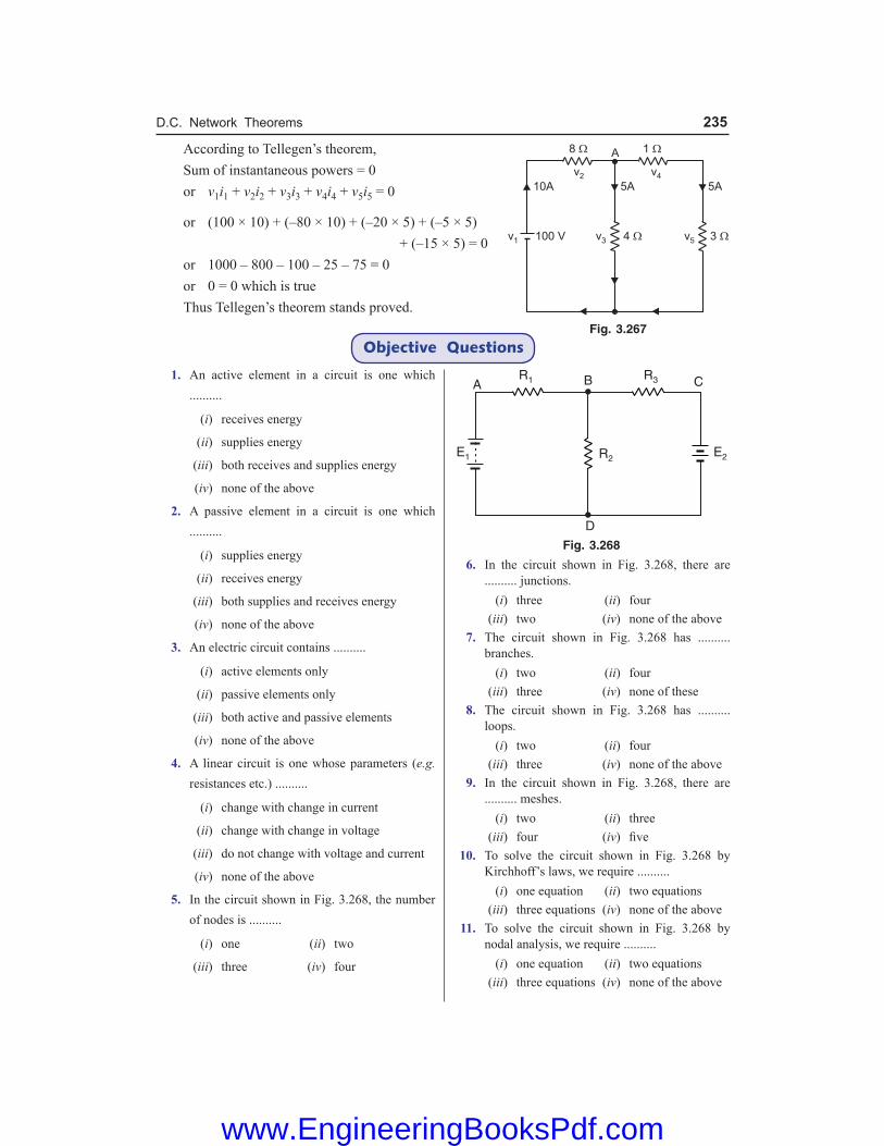
D.C. Network Theorems 235
According to Tellegen’s theorem, Sum of instantaneous powers = 0 or v1i1 + v2i2 + v3i3 + v4i4 + v5i5 = 0
or (100 × 10) + (–80 × 10) + (–20 × 5) + (–5 × 5) + (–15 × 5) = 0 or 1000 – 800 – 100 – 25 – 75 = 0 or 0 = 0 which is true Thus Tellegen’s theorem stands proved.
Objective QuestionsFig. 3.267
1. An active element in a circuit is one which ..........
(i) receives energy
(ii) supplies energy
(iii) both receives and supplies energy
(iv) none of the above
2. A passive element in a circuit is one which ..........
(i) supplies energy
(ii) receives energy
(iii) both supplies and receives energy
(iv) none of the above
3. An electric circuit contains ..........
(i) active elements only
(ii) passive elements only
(iii) both active and passive elements
(iv) none of the above
4. A linear circuit is one whose parameters (e.g. resistances etc.) ..........
(i) change with change in current
(ii) change with change in voltage
(iii) do not change with voltage and current
(iv) none of the above
5. In the circuit shown in Fig. 3.268, the number of nodes is ..........
(i) one (ii) two
(iii) three (iv) four
Fig. 3.268
6. In the circuit shown in Fig. 3.268, there are .......... junctions.
(i) three (ii) four (iii) two (iv) none of the above 7. The circuit shown in Fig. 3.268 has ..........
branches. (i) two (ii) four (iii) three (iv) none of these 8. The circuit shown in Fig. 3.268 has ..........
loops. (i) two (ii) four (iii) three (iv) none of the above 9. In the circuit shown in Fig. 3.268, there are
.......... meshes. (i) two (ii) three (iii) four (iv) five 10. To solve the circuit shown in Fig. 3.268 by
Kirchhoff’s laws, we require .......... (i) one equation (ii) two equations (iii) three equations (iv) none of the above 11. To solve the circuit shown in Fig. 3.268 by
nodal analysis, we require .......... (i) one equation (ii) two equations (iii) three equations (iv) none of the above
www.EngineeringBooksPdf.com

236 Basic Electrical Engineering
Fig. 3.269
12. To solve the circuit shown in Fig. 3.269 by superposition theorem, we require ..........
(i) one circuit (ii) two circuits (iii) three circuits (iv) none of the above 13. To solve the circuit shown in Fig. 3.269 by
Maxwell’s mesh current method, we require ..........
(i) one equation (ii) three equations (iii) two equations (iv) none of the above 14. In the circuit shown in Fig. 3.270, the voltage
at node B w.r.t. D is calculated to be 15V. The current in 3 Ω resistor will be ..........
(i) 2 A (ii) 5 A (iii) 2·5 A (iv) none of the above 15. The current in 2 Ω horizontal resistor in Fig.
3.270 is .......... (i) 10 A (ii) 5 A (iii) 2 A (iv) 2·5 A
Fig. 3.270
16. In order to solve the circuit shown in Fig. 3.270 by nodal analysis, we require ..........
(i) one equation (ii) two equations (iii) three equations (iv) none of the above 17. The superposition theorem is used when the
circuit contains .......... (i) a single voltage source (ii) a number of voltage sources (iii) passive elements only (iv) none of the above
18. Fig. 3.271 (ii) shows Thevenin’s equivalent circuit of Fig. 3.271 (i). The value of Thevenin’s voltage VTh is ..........
(i) 20 V (ii) 24 V (iii) 12 V (iv) 36 V
Fig. 3.271
19. The value of RTh in Fig. 3.271 (ii) is .......... (i) 15 Ω (ii) 3·5 Ω (iii) 6·4 Ω (iv) 7·4 Ω 20. The open-circuited voltage at terminals AB in
Fig. 3.271 (i) is .......... (i) 12 V (ii) 20 V (iii) 24 V (iv) 40 V 21. Find the value of RL in Fig. 3.272 to obtain
maximum power in RL.
Fig. 3.272
(i) 100 Ω (ii) 75 Ω (iii) 250 Ω (iv) 150 Ω 22. In Fig. 3.272, find the maximum power in RL. (i) 2 W (ii) 1·042 W (iii) 2·34 W (iv) 4·52 W
www.EngineeringBooksPdf.com

D.C. Network Theorems 237
23. What percent of the maximum power is delivered to RL in Fig. 3.273 when RL = 2RTh?
Fig. 3.273
(i) 79 % of PL (max) (ii) 65 % of PL (max) (iii) 88·89 % of PL (max) (iv) none of above 24. What percent of the maximum power is
delivered to RL in Fig. 3.273 when RL = RTh/2 ? (i) 65 % (ii) 70 % (iii) 88·89 % (iv) none of above 25. Find Millman’s equivalent circuit w.r.t.
terminals x – y in Fig. 3.274.
Fig. 3.274
(i) Single current source of 0·1A and resistance 75 Ω
(ii) Single current source of 2 A and resistance 50 Ω
(iii) Single current source of 1 A and resistance 25 Ω
(iv) none of above 26. Use superposition principle to find current
through R1 in Fig. 3.275.
Fig. 3.275
(i) 1 mA ← (ii) 2 mA ← (iii) 1·5 mA → (iv) 2·5 A ← 27. Use superposition principle to find current
through R1 in the circuit shown in Fig. 3.276.
Fig. 3.276
(i) 0·2 A ← (ii) 0·25 A → (iii) 0·125 A → (iv) 0·5 A → 28. Find Thevenin equivalent circuit to the left of
terminals x – y in Fig. 3.277.
Fig. 3.277
(i) VTh = 5 V ; RTh = 4·5 Ω (ii) VTh = 6 V ; RTh = 5 Ω (iii) VTh = 4·5 V ; RTh = 10 Ω (iv) VTh = 10 V ; RTh = 9 Ω 29. Convert delta network shown in Fig. 3.278 to
equivalent Wye network.
Fig. 3.278
(i)
(ii)
www.EngineeringBooksPdf.com

238 Basic Electrical Engineering
(iii)
(iv)
30. What percentage of the maximum power is delivered to a load if load resistance is 10 times greater than the Thevenin resistance of the source to which it is connected ?
(i) 25 % (ii) 40 % (iii) 35 % (iv) 33·06 %
Answers 1. (ii) 2. (ii) 3. (iii) 4. (iii) 5. (iv) 6. (iii) 7. (iii) 8. (iii) 9. (i) 10. (ii) 11. (i) 12. (ii) 13. (iii) 14. (ii) 15. (iv) 16. (i) 17. (ii) 18. (ii) 19. (iv) 20. (iii) 21. (iv) 22. (ii) 23. (iii) 24. (iii) 25. (i) 26. (ii) 27. (iii) 28. (iv) 29. (i) 30. (iv)
www.EngineeringBooksPdf.com

Introduction Engineering is an applied science dealing with a very large number of *physical quantities like distance, time, speed, temperature, force, voltage, resistance etc. Although it is possible to as-sign a standard unit for each quantity, it is rarely necessary to do so because many of the quantities are functionally related through experiment, derivation or definition. In the study of mechanics, for example, the units of only three quantities viz. mass, length and time need to be selected. All other quantities (e.g. area, volume, velocity, force etc.) can be expressed in terms of the units of these three quantities by means of experimental, derived and defined **relationship between the physical quantities. The units selected for these three quantities are called fundamental units. In order to cover the entire subject of engineering, three more fundamental quantities have been selected viz. †electric current, temperature and luminous intensity. Thus there are in all six fun-damental quantities (viz, mass, length, time, current, temperature and luminous intensity) which need to be assigned proper and standard units. The units of all other physical quantities can be derived from the units of these six fundamental quantities. In this chapter, we shall focus our at-tention on the mechanical, electrical and thermal units of work, power and energy.
4.1. International System of Units Although several systems were evolved to assign units to the above mentioned six fundamental quantities, only international system of units (abbreviated as SI) has been universally accepted. The units assigned to these six fundamental quantities in this system are given below.
Quantity Symbol Unit name Unit symbolLength l, L metre mMass m kilogram kgTime t second sElectric Current I ampere ATemperature T degree kelvin KLuminous I candela CdIntensity
It may be noted that the units of all other physical quantities in science and engineering (i.e. other than six fundamental or basic quantities above) can be derived from the above basic units and are called derived units. Thus unit of velocity (= 1 m/s) results when the unit of length (= 1 m) is divided by the unit of time (= 1 s). Similarly, the unit of force (= 1 newton) results when unit of mass (= 1 kg) is multiplied by the unit of acceleration (= 1 m/s2). Therefore, units of velocity and force are the derived units.
* A physical quantity is one which can be measured.** For example, by definition, speed is the distance travelled per second. Therefore, speed is related to distance
(i.e. length) and time.† For practical reasons, electric current and not charge has been taken as the fundamental quantity, though
one is derivable from the other. The important consideration which led to the selection of current as the fundamental quantity is that it serves as the link between electric, magnetic and mechanical quantities and can be readily measured.
4Units—Work, Power and Energy
www.EngineeringBooksPdf.com

240 Basic Electrical Engineering
4.2. Important Physical Quantities It is profitable to give a brief description of the following physical quantities much used in science and engineering : (i) Mass. It is the quantity of matter possessed by a body. The SI unit of mass is kilogram
(kg). The mass of a body is a constant quantity and is independent of place and position of the body. Thus the mass of a body is the same whether it is on Earth’s surface, the Moon’s surface, on the top of a mountain or down a deep well.
1 quintal = 100 kg ; 1 tonne = 10 quintals = 1000 kg (ii) Force. It is the product of mass (kg) and acceleration (m/s2). The unit of force is newton
(N) ; being the force required to accelerate a mass of 1 kg through an acceleration of 1 m/s2.
\ F = m a newtons where m = mass of the body in kg a = acceleration in m/s2
(iii) Weight. The force with which a body is attracted towards the centre of Earth is called the weight of the body. Now, force = mass × acceleration. If m is the mass of a body in kg and g is the acceleration due to gravity in m/s2, then,
Weight, W = m g newtons
As the value of g* varies from place to place on earth’s surface, therefore, the weight of the body varies accordingly. However, for practical purposes, we take g = 9·81 m/s2 so that weight of the body = 9·81 m newtons. Thus if a mass of 1 kg rests on a table, the downward force on the table i.e., weight of the body is W = 9·81 × 1 = 9·81 newtons. The following points may be noted carefully : (a) The mass of a body is a constant quantity whereas its weight depends upon the place or
position of the body. However, it is reasonably accurate to express weight W = 9·81 m newtons where m is the mass of the body in kg.
(b) Sometimes weight is given in kg. wt. units. One kg-wt means weight of mass of 1 kg i.e. 9·81 × 1 = 9·81 newtons.
\ 1 kg. wt. = 9·81 newtons Thus, when we say that a body has a weight of 100 kg, it means that it has a mass of 100 kg and that it exerts a downward force of 100 × 9·81 newtons.
4.3. Units of Work or Energy Work is said to be done on a body when a force acts on it and the body moves through some distance. This work done is stored in the body in the form of energy. Therefore, work and energy are measured in the same units. The SI unit of work or energy is joule and is defined as under : The work done on a body is one joule if a force of one newton moves the body through 1 m in the direction of force. It may be noted that work done or energy possessed in an electrical circuit or mechanical system or thermal system is measured in the same units viz. joules. This is expected because mechanical, electrical and thermal energies are interchangeable. For example, when mechanical work is transferred into heat or heat into work, the quantity of work in joules is equal to the quantity of **heat in joules.* The value of g is about 9.81 m/s2 at sea level whereas at equator, it is about 9.78 m/s2 and at each pole it
is about 9.832 m/s2.** Although heat energy was assigned a separate unit viz. calorie but the reader remembers that 1 calorie
= 4.186 joules. In fact, the thermal unit calorie is obsolete and now-a-days heat is expressed in joules.
www.EngineeringBooksPdf.com

Units—Work, Power and Energy 241
Note. To gain some appreciation for the magnitude of a joule of heat energy, it would require about 90,000 J to heat a cup of water from room temperature to boiling.
4.4. Some Cases of Mechanical Work or Energy It may be helpful to give a few important cases of work done or energy possessed in a me-chanical system : (i) When a force of F newtons is exerted on a body through
a distance ‘d’ metres in the direction of force, then, Work done = F × d joules or Nm (ii) Suppose a force of F newtons in maintained tangentially
at a radius r metres from O as shown in Fig. 4.1. In one revolution, the point of application of force travels through a distance of 2π r metres.
\ Work done in one revolution = Force × Distance moved in 1 revolution = F × 2 π r = 2π × T joules or Nmwhere T = F r is the torque. Clearly, the SI unit of torque will be joules or Nm. If the body makes N revolutions per minute, then, Work done/minute = 2π N T joules (iii) If a body of mass m kg is moving with a speed of v m/s, then kinetic energy possessed by
the body is given by ; K.E. of the body = 21
2mv joules
(iv) If a body having a mass of m kg is lifted vertically through a height of h metres and g is acceleration due to gravity in m/s2, then,
Potential energy of body = Work done in lifting the body = Force required × height = Weight of body × height = m g × h = m g h joules
4.5. Electrical Energy The SI unit of electrical work done or electrical energy expended in a circuit is also joule—ex-actly the same as for mechanical energy. It is defined as under : One joule of energy is expended electrically when one coulomb is moved through a p.d. of 1 volt. Suppose a charge of Q coulomb moves through a p.d. of V volts in time t in part AB of a circuit as shown in Fig. 4.2. Then electrical energy expended is given by ; Electrical energy expended = V Q joules = V I t joules ( Q = I t) = I2R t joules ( V = I R)
= 2V t
R joules
VIR
= ∵
It may be mentioned here that joule is also known as watt-second i.e. 1 joule = 1 watt-sec. When we are dealing with large amount of electrical energy, it is often convenient to express it in kilowatt hours (kWh). 1 kWh = 1000 watt-hours = 1000 × 3600 watt-sec or joules
Fig. 4.1
Fig. 4.2
www.EngineeringBooksPdf.com

242 Basic Electrical Engineering
\ 1 kWh = 36 × 105 joules or watt-sec Although practical unit of electrical energy is kWh, yet it is easy to see that this unit is readily convertible to joules with the help of above relation. The electricity bills are made on the basis of total electrical energy consumed by the consumer. The unit for billing of electrical energy is 1 kWh. Thus when we say that a consumer has consumed 100 units, it means the electrical energy consumption is 100 kWh. Note that 1 kWh is also called Board of Trade Unit (B.O.T.U.) or unit of electricity.
4.6. Thermal Energy Heat is a particularly important form of energy in the study of electricity, not only because it affects the electrical properties of the materials but also because it is liberated whenever electric current flows. This liberation of heat is infact the conversion of electrical energy to heat energy. The thermal energy was originally assigned the unit ‘calorie’. One calorie is the amount of heat required to raise the temperature of 1 gm of water through 1ºC. If S is the specific heat of a body, then amount of heat required to raise the temperature of m gm of body through θºC is given by ; Heat gained = (m S θ) calories It has been found experimentally that 1 calorie = 4·186 joules so that heat energy in calories can be expressed in joules as under : Heat gained = (m S θ) × 4·186 joules The reader may note that SI unit of heat is also joule. In fact, the thermal unit calorie is obsolete and unit joule is preferred these days.
4.7. Units of Power Power is the rate at which energy is expended or the rate at which work is performed. Since energy and work both have the units of joules, it follows that power, being rate, has the units joule/second. Now Joule/second is also called watt. In general,
Power = Wt
watts
where W is the total number of joules of work performed or total joules of energy expended in t seconds. Suppose a charge of Q coulomb moves through a p.d. of V volts in time t in part AB of a circuit as shown in Fig. 4.2. Then,
Electrical energy expended = VQ = VIt = I2Rt = 2V t
R
\ Power of circuit, P = VItt
= 2I Rtt
= 2V t
Rt
or P = VI = I2R = 2V
R In practice, watt is often found to be inconveniently small, consequently the unit kilowatt (kW) is used. One kW is equal to 1000 watts i.e. 1 kW = 1000 watts For larger powers, the unit megawatt (MW) is used. One megawatt is equal to 1000 kW i.e. 1 MW = 1000 kW = 1000 × 1000 watts \ 1 MW = 106 watts It may be noted that power of an electrical system or mechanical system or thermal system is measured in the same units viz joules/sec. or watts.
www.EngineeringBooksPdf.com

Units—Work, Power and Energy 243
Important points. The following points are worth noting : (i) Sometimes power is measured in *horse power (h.p.). 1 h.p. = 746 watts (ii) If a body makes N r.p.m. and the torque acting is T newton-metre, then, Work done/minute = 2π N T joules [See Art. 4·4]
Work done/sec = 2
60NTπ
joules/sec or watts
i.e., Power = 2
60NTπ
watts
Since 746 watts = 1 h.p., we have,
Power = 2
60 746NTπ
× h.p.
where T is in newton-m and N is in r.p.m. (iii) Power can also be expressed in terms of force and velocity. Power = Work done/sec = Force × distance/sec \ Power = Force × velocity
4.8. Efficiency of Electric Device The efficiency of an electric device is the ratio of useful output power to the input power, i.e.
Efficiency, η = Useful output power
Input power
= Useful output Energy
Input Energy
The law of conservation of energy states that “energy cannot be created or de-stroyed but can be converted from one form to another.’’ Some of the input energy to an electric device may be converted into a form that is not useful. For example, consider an electric motor shown in Fig. 4.3. The purpose of the motor is to convert electric energy into mechanical energy. It does this but it also converts a part of input energy into heat. The heat produced is not useful. Therefore, the useful output energy is less than the input energy. In other words, the efficiency of motor is less than 100%. While selecting an electric device, its efficiency is an important consideration because the operating cost of the device depends upon this factor. Some electric devices are nearly 100% efficient. An electric heater is an example. In a heater, the heat is useful output energy and practically all the input electric energy is converted into heat energy.
4.9. Harmful Effects of Poor Efficiency The poor (or low) efficiency of a device or of a circuit has the following harmful effects : (i) Poor efficiency means waste of energy on non-useful output.
* This unit for power was conceived by James Watt, a Scottish scientist who invented the steam engine. In his experiments, he compared the output of his engine with the power a horse could put out. He found that an “average” horse could do work at the rate of 746 joules/sec. Although power can be expressed in watts or kW, the unit h.p. is still used.
Fig. 4.3
www.EngineeringBooksPdf.com

244 Basic Electrical Engineering
(ii) Non-useful output of a device or circuit usually appears in the form of heat. Therefore, poor efficiency means a significant temperature rise. High temperature is one of the major limiting factors in producing reliable electric and electronic devices. Circuits and devices that run hot are more likely to fail.
(iii) The heat produced as a result of poor efficiency has to be dissipated i.e., heat has to be transferred to the atmosphere or some other mass. Heat removal can become quite difficult in high power circuits and adds to the cost and size of the equipment.
Example 4.1. An electrically driven pump lifts 80 m3 of water per minute through a height of 12 m. Allowing an overall efficiency of 70% for the motor and pump, calculate the input power to motor. If the pump is in operation for an average of 2 hours per day for 30 days, calculate the energy consumption in kWh and the cost of energy at the rate of Rs 2 per kWh. Assume 1 m3 of water has a mass of 1000 kg and g = 9·81 m/s2. Solution. Mass of 80 m3 of water, m = 80 × 1000 = 8 × 10⁴ kg Weight of water lifted, W = m g = 8 × 104 × 9·81 N Height through which water lifted, h = 12 m W.D. by motor/minute = m g h = 8 × 104 × 9·81 × 12 joules
W.D. by motor/second = 48 10 9.81 12
60× × ×
= 156960 watts
\ Output power of motor = 156960 watts
Input power to motor = Motor output 156960=
Efficiency 0.7 = 2,24,228 W = 224·228 kW
Total energy consumption = Input power × Time of operation
= (224·228) × (2 × 30) kWh = 13453 kWh Total cost of energy = Rs 2 × 13453 = Rs. 26906 Example 4.2. Fig. 4.4 shows an electric motor driving an electric generator. The 2 h.p. motor draws 14·6 A from a 120 V source and the generator supplies 56 A at 24 V. (i) Find the motor efficiency and generator efficiency (ii) Find the overall efficiency.
Fig. 4.4
Solution. Efficiency of a machine is output power (Po) divided by input power (Pi). (i) Pi (motor) = 120 × 14·6 = 1752 W Po (motor) = 2 h.p. = 2 × 746 = 1492 W
\ η (motor) = 14921752
= 0.8516 or 85·16%
www.EngineeringBooksPdf.com

Units—Work, Power and Energy 245
Pi (generator) = 2 h.p. = 1492 W Po (generator) = 24 × 56 = 1344 W
\ η (generator) = 13441492
= 0·90 or 90%
(ii) η (overall) = (generator) 1344
(motor) 1752o
i
PP
= = 0·767 or 76·7%
Note that overall η is the product of efficiencies of the individual machines. η (overall) = η (motor) × η (generator) = 0·8516 × 0·90 = 0·767. Example 4.3. Neglecting losses, at what horse power rate could energy be obtained from Bhakra dam which has an average height of 225 m and water flows at a rate of 500,000 kg/minute ? If the overall efficiency of conversion were 25%, how many 100 watt light bulbs could Bhakra dam supply ? Solution. Wt. of water flowing/minute = m g = 500,000 × 9·81 N Work done/minute = m g h = 500,000 × 9·81 × 225 joules
Work done/second = 500,000 9.81 225
60× ×
= 18394 × 103 watts
\ Gross power obtained = 18394 × 103 watts = 18394 kW Useful output power = 18394 × 0·25 = 4598·5 kW
= 34598.5 10
746×
h.p. = 6164 h.p.
No. of 100-watt bulbs that could be lighted
= 34598.5 10
100×
= 45985
Example 4.4. A 100 MW hydro-electric station is supplying full-load for 10 hours a day. Calcu-late the volume of water which has been used. Assume effective head of station as 200 m and overall efficiency of the station as 80%. Solution. Energy supplied by the station in 10 hours = (100 × 103) × 10 = 106 kWh = 36 × 105 × 106 = 36 × 1011 joules Energy input of station = 36 × 1011/0·8 = 45 × 1011 joules Suppose m kg is the mass of water used in 10 hours. Then, m g h = 45 × 1011
or m = 1145 10
9.81 200××
= 22.93 × 10⁸ kg
Since 1 m3 of water has a mass of 1000 kg, \ Volume of water used = 22·93 × 108/103 = 22·93 × 105 m3
Example 4.5. Two coils are connected in parallel and a voltage of 200 V is applied to the ter-minals. The total current taken is 15A and the power dissipated in one of the coils is 1500 W. What is the resistance of each coil ? Solution. Let R1 and R2 be the resistances of the coils and I1 and I2 be the current drawn from the supply. Since the coils are connected in parallel, voltage across each coil is the same i.e. 200 V.
www.EngineeringBooksPdf.com

246 Basic Electrical Engineering
V I1 = W or I1 = W/V = 1500/200 = 7·5A \ R1 = V/I1 = 200/7·5 = 26.7 Ω I1 + I2 = 15 ..... given \ I2 = 15 − I1 = 15 − 7·5 = 7·5A
\ R2 = 2
2007.5
VI
= = 26.7 Ω
Although not technically correct usage, it is convenient to say that resistance “dissipates power”, meaning that it dissipates (liberates) heat at a certain rate. Example 4.6. A motor is being self-started against a resisting torque of 60 N-m and at each start, the engine is cranked at 75 r.p.m. for 8 seconds. For each start, energy is drawn from a lead-acid battery. If the battery has the capacity of 100 Wh, calculate the number of starts that can be made with such a battery. Assume an overall efficiency of the motor and gears as 25%. Solution. Angular speed, ω = 2π N/60 rad/s = 2π × 75/60 = 7·85 rad/s
Power required per start, P = Torque × Angular speed
Efficiency of motor =
60 7.850.25×
= 1884 W
Energy required/start = P × Time for start = 1884 × 8 = 15072 Ws = 15072 J = 15072/3600 = 4·187 Wh \ No. of starts with a fully-charged battery = 100/4·187 24 Example 4.7. A hydro-electric power station has a reservoir of area 2·4 square kilometres and capacity 5 × 10⁶ m3. The effective head of water is 100 m. The penstock, turbine and generator efficiencies are 95%, 90% and 85% respectively. (i) Calculate the total energy in kWh which can be generated from the power station. (ii) If a load of 15,000 kW has been supplied for 3 hours, find the fall in reservoir level. Solution. (i) Wt. of water available, W = Volume of reservoir × 1000 × 9·81 N = (5 × 106) × (1000) × (9·81) = 49·05 × 109 N Overall efficiency, ηoverall = 0·95 × 0·90 × 0·85 = 0·726 Electrical energy that can be generated from the station = W × Effective head × ηoverall
= (49·05 × 109) × (100) × (0·726) = 35·61 × 1011 watt-sec.
= 1135.61 10
1000 3600×
× kWh = 9,89,116 kWh
(ii) Level of reservoir = 6
6
Volume of reservoir 5 10Area of reservoir 2.4 10
×=×
= 2·083 m
kWh generated in 3 hrs = 15000 × 3 = 45,000 kWh Using unitary method, we get,
Fall in reservoir level = 2.083 45,000
9,89,166× = 0·0947 m = 9·47 cm
www.EngineeringBooksPdf.com

Units—Work, Power and Energy 247
Example 4.8. A large hydel power station has a head of 324 m and an average flow of 1370 m3/sec. The reservoir is a lake covering an area of 6400 sq. km. Assuming an efficiency of 90% for the turbine and 95% for the generator, calculate (i) the available electric power and (ii) the number of days this power could be supplied for a drop in water level by 1 metre. Solution. Water discharge = 1370 m3/sec ; Water head, h = 324 m ; ηoverall = 0.9 × 0.95 (i) As mass of 1 m3 of water is 1000 kg, \ Mass of water flowing/sec, m = 1370 × 1000 kg = 137 × 104 kg Weight of water flowing/sec, W = mg = 137 × 104 × 9.81 N Energy or work available per second (i.e. power) is Power available, P = Wh × ηoverall
= (137 × 104 × 9.81) × 324 × (0.9 × 0.95) = 3723 × 106 W = 3723 MW (ii) Area of reservoir, A = 6400 km2 = 6400 × 106 m2
Rate of water discharge, Q = 1370 m3/sec Fall of reservoir level, h′ = 1 m Volume of water used = A × h′
\ Required time, t = A h
Q′×
= 66400 10 1
1370× ×
= 4.67 × 10⁶ sec. = 54.07 days Example 4.9. Calculate the current required by a 500 V d.c. locomotive when drawing 100 tonne load at 25 km/hr with a tractive resistance of 7 kg/tonne along (i) level road and (ii) a gradient 1 in 100. Given that the efficiency of motor and gearing is 70%. Solution. Weight of locomotive, W = 100 tonne = 100,000 kg Tractive resistance, F = 7 × 100 = 700 kg-wt = 700 × 9·81 = 6867 N (i) Level Track. In this case, the force required is equal to the tractive resistance F [See Fig. 4.5 (i)]. Distance travelled/sec =
25 10003600×
= 6·94 m
Work done/sec = Force × Distance/sec or Motor output = 6867 × 6·94 = 47,657 watts Motor input = 47,657/0·7 = 68,081 watts \ Current drawn = 68,081/500 = 136·16A
Fig. 4.5
www.EngineeringBooksPdf.com

248 Basic Electrical Engineering
(ii) Inclined plane. In this case, the total force required is the sum of tractive resistance F and component W sinθ of locomotive weight [See Fig. 4.5 (ii)]. Clearly, sin θ = 1/100 = 0·01. \ Force required = W sin θ + F = (100,000 × 0·01 + 700) 9·81 N = 16,677 N Work done/sec = Force × distance travelled/sec = 16,677 × 6·94 = 1,15,738 watts \ Motor output = 1,15,738 watts Motor input = 1,15,738/0·7 = 1,65,340 watts \ Current drawn = 1,65,340/500 = 330·68A Example 4.10. A diesel-electric generator set supplies an output of 25 kW. The calorific value of the fuel oil used is 12,500 kcal/kg. If the overall efficiency of the unit is 35%, calculate (i) the mass of oil required per hour (ii) the electric energy generated per tonne of the fuel. Solution. Output power of set = 25 kW ; ηoverall = 35% = 0.35 \ Input power to set = 25/0.35 = 71.4 kW (i) Input energy/hour = 71.4 kW × 1h = 71.4 kWh = 71.4 × 860 kcal As 1 kg of fuel oil produces 12,500 kcal,
\ Mass of fuel oil required/hour = 71.4 860
12,500×
= 4.91 kg
(ii) Heat content in 1 tonne fuel oil (= 1000 kg) = 1000 × 12,500 = 12.5 × 10⁶ kcal
= 612.5 10
860×
kWh = 14,534 kWh
\ Energy generated/tonne = 14,534 × 0.35 = 5087 kWh Example 4.11. The reservoir for a hydro-electric station is 230 m above the turbine house. The annual replenishment of the reservoir is 45 × 1010 kg. What is the energy available at the generating station bus-bars if the loss of head in the hydraulic system is 30 m and the overall efficiency of the station is 85% ? Also, calculate the diameter of the steel pipes needed if a maximum demand of 45 MW is to be supplied using two pipes. Solution. Actual available head, h = 230 − 30 = 200 m
Energy available at turbine house is given by ;
E = mgh = 45 × 1010 × 9·81 × 200 = 8·829 × 1014 J
= 14
5
8.829 1036 10
××
kWh = 24·52 × 107 kWh
Energy available at bus-bars = E × η = 24·52 × 107 × 0.85 = 20·84 × 107 kWh
K.E. of water = Loss of potential energy of water
or 212
mv = mgh \ v = 2 2 9.81 200gh = × × = 62·65 m/s
Power available from m kg of water is
P = 21 12 2
mv = × m × (62.65)2 W
This power is equal to 45 MW (= 45 × 106 W).
www.EngineeringBooksPdf.com

Units—Work, Power and Energy 249
\ P = 45 × 106 W
or 12
× m × (62.65)2 = 45 × 106 \ m = 22930 kg/s
If A is the total area of two pipes in m2, then flow of water is Av m3/s. \ Mass of water flowing/second = Av × 103 kg ( 1 m3 of water = 1000 kg)
\ Av × 103 = 22930 or A = 3
2293062.65 10×
= 0·366 m2
Area of each pipe = 0·366/2 = 0·183 m2
If d is the diameter of each pipe, then,
2
4dπ
= 0.183 or d = 0.183 4×
π = 0·4826 m
Example 4.12. A proposed hydro-electric station has an available head of 30 m, catchment area of 50 × 106 m2, the rainfall for which is 120 cm per annum. If 70% of the total rainfall can be collected, calculate the power that could be generated. Assume the following efficiencies: Penstock 95%, Turbine 80% and Generator 85%. Solution. Available head, h = 30 m ; ηoverall = 0.95 × 0.8 × 0.85 = 0.646
Volume of water *available/annum = 0.7(50 × 106 × 1.2) = 4.2 × 10⁷ m3
Mass of water available/annum = 4.2 × 107 × 1000 = 4.2 × 10¹⁰ kg
Mass of water available/sec; m = 104.2 10
365 24 3600×
× × = 1.33 × 10³ kg
Potential energy available/sec = mgh = 1.33 × 103 × 9.8 × 30 = 391 × 103 J/s \ Power that could be generated = ηoverall × 391 × 103 W = 0.646 × 391 × 103 = 253 × 103 W = 253 kW Example 4·13. A current of 20A flows for one hour in a resistance across which there is a volt-age of 8V. Determine the velocity in metres per second with which a weight of one tonne must move in order that kinetic energy shall be equal in amount to the energy dissipated in the resistance. Solution. Energy dissipated in resistance = V It = 8 × 20 × 3600 = 576 × 103 J Mass of body, m = 1 tonne = 1000 kg Let v m/s be the required velocity of the weight.
Kinetic energy = 212
mv joules
In order that K.E. of weight is equal to energy dissipated in resistance,
212
mv = 576 × 103 \ v = 32 576 10
1000× ×
= 33·9 m/s
Example 4·14. What must be the horse-power of an engine to drive by means of a belt a genera-tor supplying 7000 lamps each taking 0·5 A at 250 V ? The line drop is 5V and the efficiency of the generator is 95%. There is a 2·5% loss in the belt drive. Solution. Total current supplied by generator, I = 0·5 × 7000 = 3500 A Generated voltage, E = Load voltage + Line drop = 250 + 5 = 255 V Generator output = EI = 255 × 3500 W* 0.7 × (Catchment area in m2 × Rainfall in m)
www.EngineeringBooksPdf.com

250 Basic Electrical Engineering
\ Engine output = 255 3500
0.95 0.975××
= 963562 W = 963562
746 h.p. = 1292 h.p.
Example 4.15. Find the head in metres of a hydroelectric generating station in which the reservoir of area 4000 m2 falls by 30 cm when 75 kWh is developed in the turbine. The efficiency of the turbine is 70%. Solution. Hydroelectric generating stations are generally built in hilly areas.
Volume of water used, V = 4000 × 0·3 = 1200 m3
Mass of water used, m = 1200 × 103 = 1·2 × 106 kg
Useful energy developed in turbine = mgh × η = 1·2 × 106 × 9.81 × h × 0·7
But useful energy developed in turbine = 75 kWh = 75 × 3·6 × 106 J
\ 1·2 × 106 × 9·81 × h × 0·7 = 75 × 3·6 × 106
or h = 32·76 m Example 4.16. A room measures 3m × 4m × 4·75m and air in it has to be always kept 10°C higher than that of the incoming air. The air inside has to be renewed every 30 minutes. Neglecting radiation losses, find the necessary rating of electric heater for this purpose. Take specific heat of air as 0·24 and density as 1·28 kg/m3. Solution. It is desired to find the power of the electric heater.
Volume of air to be changed/second = 3 4 4.75
30 60× ×
× = 0·032 m3
Mass of air to be changed/second = 0·032 × 1·28 = 0·041 kg Heat required/second = Mass/second × Specific heat × Rise in temp. = 0·041 × 0·24 × 10 kcal = 0·041 × 0·24 × 10 × 4186 W = 411 W Here, we have neglected radiation losses. However, in practice, radiation losses do occur so that heater power required would be greater than the calculated value. Example 4.17. An electric lift is required to raise a load of 5 tonne through a height of 30 m. One quarter of electrical energy supplied to the lift is lost in the motor and gearing. Calculate the energy in kWh supplied. If the time required to raise the load is 27 minutes, find the kW rating of the motor and the current taken by the motor, the supply voltage being 230V d.c. Assume the efficiency of the motor at 90%. Solution. Work done by lift = mgh = (5 × 103) × 9.8 × 30 = 1.47 × 10⁶ J
Input energy to lift = 61.47 10
*lift
×η
= 61.47 10
0.75×
= 1.96 × 10⁶ J
= 6
5
1.96 1036 10
××
kWh = 0.545 kWh
Motor energy output = Input energy to lift = 1.96 × 10⁶ J
Motor energy input = 61.96 10
motor
×η
= 61.96 10
0.9×
= 2.18 × 10⁶ J
* Since 25% energy is wasted in the motor and gearing, the efficiency of the lift is 75%.
1 kcal 4186 Wsec.
= ∵
www.EngineeringBooksPdf.com

Units—Work, Power and Energy 251
Power rating of motor = Work doneTime taken
= 62.18 10
27 60××
= 1346 W
Current taken by motor = 1346230
= 5.85 A
Example 4.18. An electric hoist makes 10 double journeys per hour. In each journey, a load of 6000 kg is raised to a height of 60 m in 90 seconds and the hoist returns empty in 75 seconds. The hoist cage weighs 500 kg and has a balance weight of 3000 kg. The efficiency of the hoist is 80% and that of the driving motor 88%. Calculate (i) the electrical energy absorbed per double journey (ii) the hourly consumption in kWh (iii) the horse-power of the motor (iv) the cost of electric energy if hoist works for 4 hours per day for 30 days. Cost per kWh is Rs 4.50. Solution. When the hoist cage goes up, the balance weight goes down and when the cage goes down, the balance weight goes up. Total mass lifted on upward journey = Load + mass of cage − mass of balance weight = 6000 + 500 − 3000 = 3500 kg Work done during upward journey = mgh = 3500 × 9·8 × 60 J Total mass moved on downward journey = Mass of balance wt. − Mass of cage = 3000 − 500 = 2500 kg Work done during downward journey = mgh = 250 × 9·8 × 60 J Work done during each double journey = 9·8 × 60 (3500 + 2500)J = 353 × 104 J Overall η = 0·8 × 0·88 = 0·704 (i) Input energy per double journey = 353 × 104/0·704 = 501 × 104 J
= 4
6
501 103.6 10
××
kWh = 1·4 kWh
(ii) Hourly consumption = 1·4 × No. of double journeys/hr = 1·4 × 10 = 14 kWh (iii) The maximum rate of working is during upward journey.
\ h.p. rating of motor = Work done in upward journey
Hoist efficiency × time for up journey × 746
= 3500 9.8 600.8 90 746
× ×× ×
= 38·4 h.p.
(iv) Energy consumption for 30 days = Hourly consumption × 4 × 30 = 14 × 4 × 30 = 1680 kWh
Total cost of energy = Rs. 1680 × 4·5 = Rs. 7560 Example 4.19. A generator supplies power to a factory through cables of total resistance 20 ohms. The potential difference at the generator is 5000 V and power output is 50 kW. Calculate (i) power suppled by the generator, (ii) potential difference at the factory.
Solution. Fig. 4.6 shows the conditions of the problem.
Output power of generator is given by ;
P = 50 kW = 50 × 103 W
P.D. at the generator, E = 5000 V
\ Current in cables is given by ;
I = 350 10
5000PE
×= = 10 A Fig. 4.6
www.EngineeringBooksPdf.com

252 Basic Electrical Engineering
(i) Power loss in cables = I2 R = (10)2 × 20 = 2000 W \ Power supplied at the factory = 50 × 103 − 2000 = 48,000 W (ii) Voltage drop in cables = I R = 10 × 20 = 200 V \ P.D. at the factory, V = E − I R = 5000 − 200 = 4800 V
Tutorial Problems
1. The power required to drive a certain machine at 350 r.p.m. is 600 kW. Calculate the driving torque. [16370 Nm]
2. An electrically driven pump lifts 1500 litres of water per minute through a height of 25 m. Allowing an overall efficiency of 75%, calculate the input power to the motor. If the pump is in operation for an average of 8 hours per day for 30 days, calculate the energy consumed in kWh and the cost of energy at the rate of 50 P/kWh. Assume 1 litre of water has a mass of 1000 kg and g = 9·81 m/s2.
[8·167 kW, 1960 kWh, Rs. 980] 3. A 440-volt motor is used to drive an irrigation pump. The efficiency of motor is 85% and the efficiency
of pump is 66%. The pump is required to lift 240 tonne of water per hour to a height of 30 metres. Calculate the current taken by the motor. [79·48 A]
4. A hydro-electric generating plant is supplied from a reservoir of capacity 2 × 10⁷ m3 with a head of 200 m. The hydraulic efficiency of the plant is 0·8 and electric efficiency is 0·9. What is the total available energy ? [7·85 × 109 watt-hours]
5. A 460-V d.c. motor drives a hoist which raises a load of 100 kg with a velocity of 15 m/s. Calculate : (i) The power output of the motor assuming the hoist gearing to have an efficiency of 0·8. (ii) The motor current, assuming the motor efficiency to be 0·75. [(i) 18·4 kW (ii) 53·2 A]
6. When a certain electric motor is operated for 30 minutes, it consumes 0·75 kWh of energy. During that time, its total energy loss is 3 × 10⁵ J.
(i) What is the efficiency of the motor ? (ii) How many joules of work does it perform in 30 minutes ? [(i) 88·8% (ii) 2·4 × 106J]
7. The total power supplied to an engine that drives an electric generator is 40·25 kW. If the generator delivers 15A to a 100 Ω load, what is the efficiency of the system ? [55·9%]
8. A certain system consists of three identical devices in cascade, each having efficiency 0·85. The first device draws 3A from a 20V source. How much current does the third device deliver to a 50Ω load ?
[0·027 A]
4.10. Heating Effect of Electric Current When electric current is passed through a conductor, heat is produced in the conductor. This effect is called heating effect of electric current. It is a matter of common experience that when electric current is passed through the element of an electric heater, the element becomes red hot. It is because electrical energy is converted into heat energy. This is called heating effect of electric current and is utilised in the manufacture of many heating appliances, e.g., electric iron, electric kettle, etc. The basic principle of all these devices is the same. Electric current is passed through a high resistance (called heating element), thus produc-ing the required heat. Cause. Let us discuss the cause of heating effect of electric current. When potential difference is applied across the ends of a conductor, the free electrons move with drift velocity and current is established in the conductor. As the free electrons move through the conductor, they collide with positive ions of the conductor. On collision, the kinetic energy of an electron is transferred to the ion with which it has collided. As a result, the kinetic energy of vibration of the positive ion increases, i.e., temperature of the conductor increases. Therefore, as current flows through a conductor, the
www.EngineeringBooksPdf.com

Units—Work, Power and Energy 253
free electrons lose energy which is converted into heat. Since the source of e.m.f. (e.g., a battery) is maintaining current in the conductor, it is clear that electrical energy supplied by the battery is converted into heat in the conductor. Applications. The heating effect of electric current is utilised in the manufacture of many heat-ing appliances such as electric heater, electric toaster, electric kettle, soldering iron etc. The basic principle of all these appliances is the same. Electric current is passed through a high resistance (called heating element), thus producing the required heat. There are a number of substances used for making a heating element. One that is commonly used is an alloy of nickel and chromium, called nichrome. This alloy has a resistance more than 50 times that of copper. The heating element may be either nichrome wire or ribbon wound on some insulating material that is able to withstand heat.
4.11. Heat Produced in a Conductor by Electric Current On the basis of his experimental results, Joule found that the amount of heat produced (H) when current I amperes flows through a conductor of resistance R ohms for time t seconds is H = I2Rt joules. This equation is known as Joule’s law of heating. Suppose a battery maintains a potential difference of V volts across the ends of a conductor AB of resistance R ohms as shown in Fig. 4.7. Let the steady current that passes from A to B be I amperes. If this current flows for t seconds, then charge transferred from A to B in t seconds is q = It The electric potential energy lost (W) by the charge q as it moves from A to B is given by ; W = Charge × P.D. between A and B
= qV = (It) V = I2Rt (V = IR)
or W = I2Rt This loss of electric potential energy of charge is converted into heat (H) because the conductor AB has resistance only. \ H = W = I2Rt joules =
2
4.18I Rt
calories ...(i)
It is found experimentally that 1 cal = 4.18 J. Eq. (i) is known as Joule’s law of heating. It is because Joule was the first scientist who studied the heating effect of electric current through a resistor. Thus according to Joule, heat produced in a conductor is directly proportional to (i) square of current through the conductor (ii) resistance of the conductor (iii) time for which current is passed through the conductor.
Note. H = VIt = I2Rt = 2V t
R joules
= 4.18VIt
= 2 2
4.18 4.18I Rt V t
R=
×calories
Important points. While dealing with problems on heating effect of electric current, the following points may be kept in mind : (i) The electrical energy in kWh can be converted into joules by the following relation : 1 kWh = 36 × 105 joules
Fig. 4.7
V
R
A B
I
www.EngineeringBooksPdf.com

254 Basic Electrical Engineering
(ii) The heat energy in calories can be converted into joules by the following relation : 1 calorie = 4·186 joules 1 kcal = 4186 joules (iii) The electrical energy in kWh can be converted into calories (or kilocalories) by the
following relation :
1 kWh = 36 × 105 joules = 536 10
4.186×
calories = 860 × 103 calories
\ 1 kWh = 860 kcal (iv) The electrical energy supplied to the heating appliance forms the input energy. The heat
obtained from the device is the output energy. The difference between the two, if any, represents the loss of energy during conversion from electrical into heat energy.
4.12. Mechanical Equivalent of Heat (J) Joule performed a series of experiments to establish the relationship between the mechani-cal work done and heat produced. He found that heat produced (H) is directly proportional to the amount of mechanical work done (W) i.e.,
H ∝ W or W = JHwhere J is a constant of proportionality and is called mechanical equivalent of heat. The experimen-tally found value of J is J = 4·2 J/cal Note that J is a numerical factor relating mechanical units to heat units. Let us interpret the meaning of J. It takes 4·2 J of mechanical work to raise the temperature of 1g of water by 1°C. In other words, 4·2J of mechanical energy is equivalent to 1 calorie of heat energy. Example 4.20. In Fig. 4.8, the heat produced in 5 Ω resistor due to current flowing through it is 10 calories per second. Calculate the heat generated in 4 Ω resistor. Solution. Let I1 and I2 be the currents in the two parallel branches as shown in Fig. 4.8. The p.d. across the parallel branches is the same i.e. I1 (4 + 6) = 5 I2 \ I2 = 2 I1
Heat produced per second in 5Ω resistor is
H1 = 22 54.2
I ×
or 10 = 2
1(2 ) 54.2
I ×
\ I12 = 2·1
Heat produced in 4Ω resistor per second
= 2
1 4 2.1 44.2 4.2
I × ×= = 2 cal/sec
Example 4.21. An electric heater contains 4 litres of water initially at a mean temperature of 15ºC. 0·25 kWh is supplied to the water by the heater. Assuming no heat losses, what is the final temperature of the water ? Solution. Let tºC be the final temperature of water. Heat received by water (i.e. output energy) = mass × sp. heat × rise in temp. = 4 × 1 × (t − 15) kcal
Fig. 4.8
www.EngineeringBooksPdf.com

Units—Work, Power and Energy 255
Electrical energy supplied to heater (i.e. input energy) = 0·25 kWh = 0·25 × 860 kcal ( 1 kWh = 860 kcal) As there are no losses, output energy is equal to the input energy i.e. 4 × 1 × (t − 15) = 0·25 × 860 or t = 68·8ºC Example 4.22. An immersion heater takes 1 hour to heat 50 kg of water from 20ºC to boiling point. Calculate the power rating of the heater, assuming the heating equipment to have an efficiency of 90%. Solution. Heat received by water (i.e. output energy) = mass × specific heat × rise in temperature = 50 × 1 × 80 = 4000 kcal = 4000/860 = 4·65 kWh Electrical energy supplied to heater (i.e. input energy) = 4·65/0·9 = 5·167 kWh
\ Power rating = Energy 5.167Time 1 hour
= = 5.167 kW
Example 4.23. The cost of boiling 2 kg of water in an electric kettle is 12 paise. The kettle takes 6 minutes to boil water from an ambient temperature of 20ºC. Calculate (i) the efficiency of kettle and (ii) the wattage of kettle if cost of 1 kWh is 40 paise. Solution. (i) Heat received by water (i.e. output energy) = 2 × 1 × 80 = 160 kcal Electrical energy supplied (i.e. input energy) = 12/40 kWh = 860 × 12/40 = 258 kcal
\ Kettle efficiency = 160 100258
× = 62%
(ii) Let W kilowatt be the power rating of the kettle. Input energy = W × time in hours or 12/40 = W × 6/60
\ Wattage of kettle, W = 12 6040 6
× = 3 kW
Example 4.24. How long will it take to raise the temperature of 880 gm of water from 16ºC to boiling point ? The heater takes 2 amperes at 220 V and its efficiency is 90%. Solution. Heat received by water (i.e. output energy) = 0·88 × 1 × (100 − 16) = 73·92 kcal = 73·92/860 = 0·086 kWh Electrical energy supplied to the heater (i.e. input energy) = 0·086/0·9 = 0·096 kWh The heater is supplying a power of 220 × 2 = 440 watts = 0·44 kW. Let t hours be the required time. Input energy = wattage × time or 0·096 = 0·44 × t \ t = 0·096/0·44 = 0·218 hours = 0·218 × 60 = 13·08 minutes Example 4.25. An electric kettle is required to raise the temperature of 2 kg of water from 20ºC to 100ºC in 15 minutes. Calculate the resistance of the heating element if the kettle is to be used on a 240 volts supply. Assume the efficiency of the kettle to be 80%.
www.EngineeringBooksPdf.com

256 Basic Electrical Engineering
Solution. Heat received by water (i.e. output energy) = 2 × 1 × (100 − 20) = 160 kcal = 160/860 = 0·186 kWh Electrical energy supplied to the kettle = 0·186/0·8 = 0·232 kWh The electrical energy of 0·232 kWh is supplied in 15/60 = 0·25 hours. \ Power rating of kettle = 0·232/0·25 = 0·928 kW = 928 watts Let R ohms be the resistance of the heating element.
\ V2/R = 928 or R = 240 240
928×
= 62 Ω
Example 4.26. The heater element of an electric kettle has a constant resistance of 100 Ω and the applied voltage is 250 V. Calculate the time taken to raise the temperature of one litre of water from 15°C to 90°C assuming that 85% of the power input to the kettle is usefully employed. If the wa-ter equivalent of the kettle is 100g, find how long will it take to raise a second litre of water through the same temperature range immediately after the first.
Solution. Mass of water, m = 1 litre = 1 kg ; q = 90 – 15 = 75°C ; S = 1 Heat taken by water = mSq = 1 × 1 × 75 = 75 kcal Heat taken by kettle = water equivalent of kettle × q = 0.1 × 75 = 7.5 kcal Heat taken by both = 75 + 7.5 = 82.5 kcal
Now, I = 250100
= 2.5 A ; J = 4200 J/kcal
Heat produced electrically = 2I RtJ
kcal ... t in seconds
Heat available for heating = 2
0.85 I RtJ
× kcal
or 2
0.85 I RtJ
× = 82.5
or 2(2.5) 1000.854200
t× ×× = 82.5
\ t = 652 s = 10 min. 52 seconds In the second case, heat would be required to heat water only because kettle would be already hot.
\ 20.85 (2.5) 100
4200t× × ×
= 75 or t = 9 min. 53 seconds
As expected, the time required for heating in the second case is less than the first case. Example 4.27. The heaters A and B are in parallel across the supply voltage V. Heater A pro-duces 500 kcal in 20 minutes and B produces 1000 kcal in 10 minutes. The resistance of heater A is 10 Ω. What is the resistance of heater B ? If the same heaters are connected in series, how much heat will be produced in 5 minutes ? Solution. Heat produced =
2V tR J×
kcal
For heater A, 500 = 2 (20 60)
10V
J× ×
× ...(i)
For heater B, 1000 = 2 (10 60)V
R J× ×
× ....(ii)
www.EngineeringBooksPdf.com

Units—Work, Power and Energy 257
Dividing eq. (i) by eq. (ii), we get,
500
1000 =
20 6010 60 10
R× ××
\ R = 2·5 Ω
When the heaters are connected in series, the total resistance becomes RT = 10 + 2·5 = 12·5 Ω. \ Heat produced in 5 minutes
= 2 2
T T
V t V tR J J R
= ××
= 5,000 5 60
20 60 12.5××
× = 100 kcal 2
From eq. ( )5000
20 60
iVJ
= ×
Example 4.28. A soldering iron is rated at 50 watts when connected to a 250 V supply. If the soldering iron takes 5 minutes to heat to a working temperature of 190°C from 20°C, find its mass, assuming it to be made of copper. Given specific heat capacity of copper is 390 J/kg°C. Solution. Let m kg be the mass of soldering iron. Heat gained by the soldering iron = mSθ = m × 390 × (190 – 20) = 66,300 m joules Heat released by the heating element = power × time = (50) × (5 × 60) = 15,000 joules Assuming all the heat released by the element is absorbed by the copper i.e. soldering iron is 100% efficient, 15,000 = 66,300 m \ m = 15,000/66,300 = 0.226 kg Example 4.29. A cubic water tank has surface area of 6 m2 and is filled to 90% capacity 6 times daily. The water is heated from 20°C to 65°C. The losses per square metre of tank surface per 1°C temperature difference are 6.3 W. Find the loading in kW and the efficiency of the tank. Assume specific heat of water = 4200 J/kg/°C and 1 kWh = 3.6 MJ.
Solution. Rise in temp, q = 65 – 20 = 45°C ; S = 4200 J/kg/°C. If l metres is one side of the tank, then surface area of the tank is 6l2. \ 6l2 = 6m2 or l = 1m Volume of tank = l3 = (1)3 = 1m3
Volume of water to be heated daily = 6 × 0.9 = 5.4 m3. As the mass of 1 m3 of water is 1000 kg, \ Mass of water to be heated daily, m = 5.4 × 1000 = 5400 kg Heat required to heat water to the desired temperature is H1 = mSq = 5400 × 4200 × 45 = 1020.6 × 106 J
= 6
5
1020.6 1036 10
××
kWh = 283.5 kWh
Heat losses, H2 = 6.3 6 24
1000× × θ ×
kWh
= 6.3 6 45 24
1000× × ×
= 40.82 kWh
Total energy supplied, H = H1 + H2 = 283.5 + 40.82 = 324.32 kWh
Loading in kW = 24 hr
H = 324.32 kWh
24 hr = 13.5 kW
Efficiency of tank = 1 100HH
× = 283.5 100
324.32× = 87.4%
www.EngineeringBooksPdf.com

258 Basic Electrical Engineering
Example 4.30. An electric furnace is being used to melt 10 kg of aluminium. The initial tem-perature of aluminium is 20°C. Assume the melting point of aluminium to be 660°C, its specific heat capacity to be 950 J/kg°C and its specific latent heat of fusion to be 387000 J/kg. Calculate the power required to accomplish the conversion in 20 minutes, assuming the efficiency of conversion to be 75%. What is the cost of energy consumed if tariff is 50 paise per kWh ? Solution. Heat used to melt aluminium (i.e. output energy) = 10 × 950 × (660 − 20) + 10 × 387000 = 995 × 104 joules
= 4
5
995 1036 10
××
= 2·76 kWh
Electrical energy supplied to the heating element = 2·76/0·75 = 3·68 kWh This much energy (i.e. 3·68 kWh) is to be supplied in 20/60 = 1/3 hour.
\ Power required = 3.681 3
= 3·68 × 3 = 11·04 kW
Cost of energy = Rs. 0·5 × 3·68 = Rs. 1·84 Example 4.31. A transmitting valve is cooled by water circulating through its hollow elec-trodes. The water enters the valve at 25°C and leaves it at 85°C. Calculate the rate of flow in kg/second needed per kW of cooling. The temperature of 1 kg of water is raised to 1°C by 4178 joules. Solution. Heat to be taken away/sec = 1 kW × 1 sec = 1000 × 1 = 1000 joules. Let the required flow of water be m kg per second. Heat produced/sec = mass × Sp. heat × rise in temp. = m × 4178 × (85 − 25) = 250,680 m joules
\ 250,680 m = 1000 or m = 1000
250,680 = 0·004 kg/sec
Tutorial Problems 1 . An electric kettle marked 1 kW, 230 V, takes 7·5 minutes to bring 1 kg of water at 15ºC to boiling
point (100ºC). Find the efficiency of the kettle. [79·07%] 2. An electric kettle contains 1·5 kg of water at 15ºC. It takes 2·5 hours to raise the temperature
to 90ºC. Assuming the heat losses due to radiation and heating the kettle to be 15 kcal, find (i) wattage of the kettle and (ii) current taken if supply voltage is 230 V. [(i) 59·2 W (ii) 0·257 A]
3. A soldering iron is rated at 50 watts when connected to a 250 V supply. If the soldering iron takes 5 minutes to heat to a working temperature of 190ºC from 20ºC, find its mass, assuming it to be made of copper. Given specific heat capacity of copper is 390 J/kgºC. [0·226 kg]
4. Find the amount of electrical energy expended in raising the temperature of 45 litres of water by 75ºC. To what height could a weight of 5 tonnes be raised with the expenditure of the same energy ? Assume efficiencies of heating and lifting equipment to be 90% and 70% respectively
[4·36 kWh, 224 m] 5. Calculate the time taken for a 25 kW furnace, having an overall efficiency of 80% to melt 20 kg of
aluminium. Take the specific heat capacity, melting point and latent heat of fusion of aluminium as 896 J/kgºC, 657ºC and 402 kJ/kg respectively. [16 min 13 sec]
6. An electric boiler has two heating elements each of 230 V, 3·5 kW rating and containing 8 litres of water at 30ºC. Assuming 10% loss of heat from the boiler, find how long after switching on the heater circuit will the water boil at atmospheric pressure
(i) if the two elements are in parallel (ii) if the two elements are in series ? The supply voltage is 230 V. [(i) 373·3 s (ii) 1493·2 s] 7. A coil of resistance 100 Ω is immersed in a vessel containing 0·5 kg of water at 16ºC and is
connected to a 220 V electric supply. Calculate the time required to boil away all the water. Given J = 4200 J/kcal; latent heat of steam = 536 kcal/kg. [44 min 50 sec]
www.EngineeringBooksPdf.com

Units—Work, Power and Energy 259
1. A 25W, 220 V bulb and a 100 W, 220 V bulb are joined in parallel and connected to 220 V supply. Which bulb will glow more brightly ?
(i) 25 W bulb (ii) 100 W bulb (iii) both will glow with same brightness (iv) neither bulb will glow 2. A 25 W, 220 V bulb and a 100 W, 220 V bulb are
joined in series and connected to 220 V supply. Which bulb will glow brighter ?
(i) 25 W bulb (ii) 100 W bulb (iii) both will glow with same brightness (iv) neither bulb will glow 3. You are given three bulbs of 25 W, 40 W and
60 W. Which of them has the lowest resistance ? (i) 25 W bulb (ii) 40 W bulb (iii) 60 W bulb (iv) information incomplete 4. You have the following electric appliances : (a) 1 kW, 250 V electric heater (b) 1 kW, 250 V electric kettle (c) 1 kW, 250 V electric bulb Which of these has the highest resistance ? (i) heater (ii) kettle (iii) all have equal resistances (iv) electric bulb 5. The time required for 1 kW electric heater
to raise the temperature of 10 litres of water through 10ºC is
(i) 210 sec (ii) 420 sec (iii) 42 sec (iv) 840 sec 6. Two electric bulbs rated at P1 watt, V volt and
P2 watt, V volt are connected in series across V volt. The total power consumed is
(i) P1 + P2 (ii) 1 2PP
(iii) 1 2
2P P+
(iv) 1 2
1 2
PPP P+
7. A tap supplies water at 22ºC. A man takes 1 litre of water per minute at 37ºC from the
geyser. The power of geyser is (i) 1050 W (ii) 1575 W (iii) 525 W (iv) 2100 W 8. A 3ºC rise in temperature is observed in a
conductor by passing a certain amount of current. When the current is doubled, the rise in temperature is
(i) 15ºC (ii) 12ºC (iii) 9ºC (iv) 3ºC 9. How much electrical energy in kWh is
consumed in operating ten 50 W bulbs for 10 hours in a day in a month of 30 days ?
(i) 500 (ii) 15000 (iii) 150 (iv) 15 10. Two heater wires of equal length are first
connected in series and then in parallel. The ratio of heat produced in the two cases will be
(i) 2 : 1 (ii) 1 : 2 (iii) 4 : 1 (iv) 1 : 4 11. Two identical heaters each marked 1000 W, 250
V are placed in series and connected to 250 V supply. Their combined rate of heating is
(i) 500 W (ii) 2000 W (iii) 1000 W (iv) 250 W 12. A constant voltage is applied between the
ends of a uniform metallic wire. Some heat is developed in it. If both length and radius of the wire are halved, the heat developed during the same duration will become
(i) half (ii) twice (iii) one fourth (iv) same 13. What is immaterial for a fuse ? (i) its specific resistance (ii) its radius (iii) its length (iv) current flowing through it 14. If the current in an electric bulb drops by 2%,
then power decreases by (i) 1% (ii) 2% (iii) 4 % (iv) 16% 15. The fuse wire is made of (i) tin-lead alloy (ii) copper (iii) tungsten (iv) nichrome
Answers 1. (ii) 2. (i) 3. (iii) 4. (iii) 5. (ii) 6. (iv) 7. (i) 8. (ii) 9. (iii) 10. (iv) 11. (i) 12. (i) 13. (iii) 14. (iii) 15. (i)
Objective Questions
www.EngineeringBooksPdf.com

Introduction So far we have discussed that if two oppositely charged bodies are connected through a conduc-tor, electrons will flow from the negative charge (excess of electrons) to the positive charge (defi-ciency of electrons). This directed flow of electrons is called electric current. The electric current will continue to flow so long as the ‘excess’ and ‘deficiency’ of electrons exist in the bodies. In other words, electric current will continue to flow so long as we maintain the potential difference between the bodies. The branch of engineering which deals with the flow of electrons (i.e. electric current) is called current electricity and is important in many ways. For example, it is the electric current by means of which electrical energy can be transferred from one point to another for utilisation. There can be another situation where charges (i.e. electrons) do not move but remain static or stationary on the bodies. Such a situation will arise when the charged bodies are separated by some insulating medium, disallowing the movement of electrons. This is called static electricity and the branch of engineering which deals with static electricity is called electrostatics. Although current electricity is of greater practical use, yet the importance of static electricity cannot be ignored. Many of the advancements made in the field of electricity owe their developments to the knowledge scien-tists obtained from electrostatics. The most useful outcomes of static electricity are the development of lightning rod and the capacitor. In this chapter, we shall confine our attention to the behaviour and applications of static electricity.
5.1. Electrostatics The branch of engineering which deals with charges at rest is called electrostatics. When a glass rod is rubbed with silk and then separated, the former becomes positively charged and the latter attains equal negative charge. It is because during rubbing, some electrons are trans-ferred from glass to silk. Since glass rod and silk are separated by an insulating medium (i.e., air), they retain the charges. In other words, the charges on them are static or stationary. Note that the word ‘electrostatic’ means electricity at rest.
5.2. Importance of Electrostatics During the past century, there was considerable increase in the practical importance of electro-statics. A few important applications of electrostatics are given below : (i) Electrostatic generators can produce voltages as high as 106 volts. Such high voltages are
required for X-ray work and nuclear bombardment. (ii) We use principles of electrostatics for spray of paints, powder, etc. (iii) The principles of electrostatics are used to prevent pollution. (iv) The problems of preventing sparks and breakdown of insulators in high voltage engineering
are essentially electrostatic. (v) The development of lightning rod and capacitor are the outcomes of electrostatics.
5.3. Methods of Charging a Conductor An uncharged conductor can be charged by the following two methods : (i) By conduction (ii) By induction
5Electrostatics
www.EngineeringBooksPdf.com

Electrostatics 261
(i) By conduction. In this method, a charged body is brought in contact with the uncharged conductor. Fig. 5.1 (i) shows the uncharged conductor B kept on an insulating stand. When the positively charged conductor A provided with insulating handle is touched with uncharged conductor B [See Fig. 5.1 (ii)], free electrons from conductor B move to conductor A. As a result, there occurs a deficit of electrons in conductor B and it becomes positively charged. Similarly, if the conductor A is negatively charged, the conductor B will also get negatively charged.
Fig. 5.1 It may be noted that conductor A is provided with an insulting handle so that its charge does
not escape to the ground through our body. For the same reason, the conductor B is kept on the insulating stand.
(ii) By Induction. In this method, a charged body is brought close to the uncharged conductor but does not touch it. Fig. 5.2 (i) shows a negatively charged plastic rod (provided with insulating handle) kept near an uncharged metal sphere. The free electrons of the sphere near the rod are repelled to the farther end. As a result, the region of the sphere near the rod becomes positively charged and the farthest end of sphere becomes equally negatively charged. If now the sphere is connected to the ground through a wire as shown in Fig. 5.2 (ii), its free electrons at the farther end flow to the ground. On removing the wire to the ground [See Fig. 5.2 (iii)], the positive charge at the near end of sphere remains held there due to the attractive force of external negative charge. Finally, when the plastic rod is removed [See Fig. 5.2 (iv)], the positive charge spreads uniformly on the sphere. Thus, the sphere is positively charged by induction. Note that in the process, the negatively charged plastic rod loses none of its negative charge. Similarly, the metal sphere can be negatively charged by bringing a positively charged rod near it.
Fig. 5.2
Note that charging a body by induction requires no contact with the body inducing the charge. This is in contrast to charging a body by conduction which does require contact between the two bodies.
5.4. Coulomb’s Laws of Electrostatics Charles Coulomb, a French scientist, observed that when two charges are placed near each other, they experience a force. He performed a number of experiments to study the nature and magnitude of the force between the charged bodies. He summed up his conclusions into two laws, known as Coulomb’s laws of electrostatics.
www.EngineeringBooksPdf.com

262 Basic Electrical Engineering
First law. This law relates to the nature of force between two charged bodies and may be stated as under : Like charges repel each other while unlike charges attract each other. In other words, if two charges are of the same nature (i.e. both positive or both negative), the force between them is repulsion. On the other hand, if one charge is positive and the other negative, the force between them is an attraction. Second law. This law tells about the magnitude of force between two charged bodies and may be stated as under : The force between two *point charges is directly proportional to the product of their magni-tudes and inversely proportional to the square of distance between their centres.
Mathematically, F ∝ 1 22
Q Qd
or F = 1 22
Q Qkd
...(i)
where k is a constant whose value depends upon the medium in which the charges are placed and the system of units employed. In SI units, force is measured in newtons, charge in coulombs, distance in metres and the value of k is given by ; k =
0
14 rπε ε
where ε0 = Absolute permittivity of vacuum or air.
εr = Relative permittiv-ity of the medium in which the charges are placed. For vacuum or air, its value is 1.
The value of ε0 = 8·854 × 10−12 F/m and the value of εr is different for different media.
\ F = 1 22
04 r
Q Qdπε ε
...(ii)
Now 0
14πε
= 12
14 8.854 10−π × ×
= 9 × 10⁹
\ F = 9 1 229 10
r
Q Qd
×ε
...in a medium
= 9 1 229 10 Q Q
d× ...in air
Unit of charge. The unit of charge (i.e. 1 coulomb) can also be defined from Coulomb’s second law of electrostatics. Suppose two equal charges placed 1 m apart in air exert a force of 9 × 10⁹ newtons i.e. Q1 = Q2 = Q ; d = 1m ; F = 9 × 10⁹ N
\ F = 9 1 229 10 Q Q
d×
or 9 × 109 = 2
929 10
(1)Q×
* Charged bodies approximate to point charges if they are small compared to the distance between them.
Fig. 5.3
www.EngineeringBooksPdf.com

Electrostatics 263
or Q2 = 1 or Q = ± 1 = 1coulomb Hence one coulomb is that charge which when placed in air at a distance of one metre from an equal and similar charge repels it with a force of 9 × 10⁹ N. Note that coulomb is very large unit of charge in the study of electrostatics. In practice, charges produced experimentally range between pico-coulomb (pC) and micro-coulomb (µC). 1pC = 10−12C ; 1µC = 10−6C Note. One disadvantage of SI units is that coulomb is an inconveniently large unit. This is clear from the fact that the force exerted by a charge of 1C on another equal charge at a distance of 1m is 9 × 10⁹N. Could you hold two one-coulomb charges a metre apart ?
5.5. Absolute and Relative Permittivity Permittivity is the property of a medium and affects the magnitude of force between two point charges. The greater the permittivity of a medium, the lesser the force between the charged bodies placed in it and vice-versa. Air or vacuum has a minimum value of permittivity. The absolute (or actual) permittivity ε0 (Greek letter ‘epsilon’) of air or vacuum is 8·854 × 10−12 F/m. The absolute (or actual) permittivity ε of all other insulating materials is greater than ε0. The ratio ε/ε0 is called the *relative permittivity of the material and is denoted by εr i.e.
εr = 0
εε
where ε = absolute (or actual) permittivity of the material ε0 = absolute (actual) permittivity of air or vacuum (8·854 × 10−12 F/m) εr = relative permittivity of the material. Obviously, εr for air would be ε0/ε0 = 1. Permittivity of a medium plays an important role in electrostatics. For instance, the relative permittivity of insulating oil is 3. It means that for the same charges (Q1 and Q2) and distance (d), the force between the two charges in insulating oil will be one-third of that in air [See eq. (ii) in Art.5·4].
5.6. Coulomb’s Law in Vector Form Consider two like point charges Q1 and Q2 separated by distance d in vacuum. Clearly, charges will repel each other [See Fig. 5.4].
Let 21F→
= force on Q2 due to Q1
12F→
= force on Q1 due to Q2
12d = unit vector pointing from Q1 to Q2
21d = unit vector pointing from Q2 to Q1
According to Coulomb’s law,
21F→
= 1 2122
Q Qk dd
or 21F→
= 1 2122
0
14
Q Q ddπε
...(i)
Similarly, 12F→
= 1 2212
0
1 ˆ4
Q Q ddπε
...(ii)
Eqs. (i) and (ii) express Coulomb’s law in vector form.
Fig. 5.4
* Thus when we say that relative permittivity of a material is 10, it means that its absolute or acutal permittivity e = e0 er = 8.854 × 10–12 × 10 = 8.854 × 10⁻¹¹ F/m.
www.EngineeringBooksPdf.com

264 Basic Electrical Engineering
Importance of vector form. The reader may wonder about the utility of Coulomb’s law in vec-tor form over the scalar form. The answer will be readily available from the following discussion :
(i) The vector form shows at a glance that forces 21F→
and 12F→
are equal and opposite.
21F→
= 1 2122
0
14
Q Q ddπε
12F→
= 1 2212
0
14
Q Q ddπε
As 12d = − 21d
\ 21F→
= − 12F→
That is 21F→
is equal in magnitude to 12F→
but opposite in direction. The scalar form does not show this fact. This is a distinct advantage over the scalar form.
(ii) 21F→
= 12F→
−
This means that 21F→
and 12F→
act along the same line i.e. along the line joining charges Q1 and Q2. In other words, the electrostatic force between two charges is a central force i.e. it acts along the line joining the centres of the two charges. However, scalar form does not show such a nature of electrostatic force between two charges.
5.7. The Superposition Principle If we are given two charges, the electrostatic force between them can be found by using Cou-lomb’s laws. However, if a number of charges are present, the force on any charge due to the other charges can be found by superposition principle stated below : When a number of charges are present, the total force on a given charge is equal to the vector sum of the forces due to the remaining other charges on the given charge. This simply means that we first find the force on the given charge (by Coulomb’s laws) due to each of the other charges in turn. We then determine the total or net force on the given charge by finding the vector sum of all the forces. Notes. (i) Consider two charges Q1 and Q2 located in air. If a third charge Q3 is brought nearby, it has been found experimentally that presence of the third charge (Q3) has no effect on the force between Q1 and Q2. This fact permits us to use superposition principle for electric forces. (ii) The superposition principle holds good for electric forces and electric fields. This fact has made the mathematical description of electrostatic phenomena simpler than it otherwise would be. (iii) We can use superposition principle to find (a) net force (b) net field (c) net flux (d) net potential and (e) net potential energy due to a number of charges. Example 5.1. A small sphere is given a charge of + 20µC and a second sphere of equal diameter is given a charge of −5 µC. The two spheres are allowed to touch each other and are then spaced 10 cm apart. What force exists between them ? Assume air as the medium. Solution. When the two spheres touch each other, the resultant charge = (20) + (−5) = 15 µC. When the spheres are separated, charge on each sphere, Q1 = Q2 = 15/2 = 7·5 µC.
\ Force, F = 9 1 229 10 Q Q
d× ×
= 6 6
92
(7.5 10 ) (7.5 10 )9 10(0.1)
− −× ×× × = 50.62 N repulsive
www.EngineeringBooksPdf.com

Electrostatics 265
Example 5.2. A charge q is divided into two parts in such a way that they repel each other with a maximum force when held at a certain distance apart. Find the distribution of the charge. Solution. Let the two parts be q′ and (q − q′). Therefore, force F between them is
F = 20
1 ( )4
q q qd
′ ′−πε
= 2
20
14
qq qd′ ′−
πε
For maximum value of F, dFdq′ = 0 \
dFdq′ = 2
0
1 ( 2 )4
q qd
′−πε
= 0
or q − 2q′ = 0 \ q′ = 2q
Hence in order to have maximum force, q should be divided into two equal parts.
Example 5.3. Three point charges of + 5µC, + 5µC and + 5µC are placed at the vertices of an equilateral triangle which has sides 10 cm long. Find the force on each charge. Solution. The conditions of the problem are represented in Fig. 5.5. Consider + 5µC placed at the corner C. It is being repelled by the charges at A and B along ACD and BCE respectively. These two forces are equal, each being given by ;
F = 6 6
92
(5 10 ) (5 10 )9 10(0.1)
− −× ×× = 22.5 N
Resultant force at C = 2F cos 30° = 2 × 22.5 × 3
2 = 38.97 N
The forces acting on the charges placed at A and B will also be the same (i.e., 38.97 N) Example 5.4. Two small spheres, each having a mass of 0·1g are suspended from a point by threads 20 cm long. They are equally charged and they repel each other to a distance of 24cm. What is the charge on each sphere ? Solution. Fig. 5.6 shows the conditions of the problem. Let B and C be the spheres, each carrying a charge q. The force of repulsion between the spheres is given by ;
F = 2
929 10
(0.24)q×
= 156.25 × 10⁹ q2
Each sphere is under the action of three forces : (i) weight m g acting vertically downward, (ii) tension T, and (iii) electrostatic force F. Considering the sphere B and resolving T into rectangular components, we have, m g = T sin θ ; F = T cos θ \ tan θ = mg/F
Now, AD = 2 2 2 2(20) (12)AB BD− = − = 16 cm
\ tan θ = 1612
ADBD
= \ 1612
mgF
=
Fig. 5.5
Fig. 5.6
www.EngineeringBooksPdf.com

266 Basic Electrical Engineering
or F = 1216
mg = 0.75 mg = 0.75 × 10–4 × 9.8 = 7.4 × 10⁻⁴ N
But F = 156·25 × 109 q2
\ 156·25 × 109 q2 = 7·4 × 10−4 or q2 = 4
9
7.4 10156.25 10
−××
= 4.8 × 10⁻¹⁵
\ q = 6·9 × 10−8 C Example 5.5. Two point charges +Q and +4Q are placed at a distance ‘a’ apart on a horizontal plane. Where should the third charge be placed for it to be in equilibrium ? Solution. Let the point charge +q be placed at a distance x from the charge +4Q [See Fig. 5.7].
Fig. 5.7
Force on charge +q due to charge +4Q is
F1 = 20
(4 )4q Q
xπε from A to B
Force on charge +q due to charge +Q is
F2 = 20
( )4 ( )
q Qa xπε −
from B to A
In order that charge +q is in equilibrium, F1 = F2.
\ 20
(4 )4q Q
xπε = 2
0
( )4 ( )
q Qa xπε −
or x = 2a/3
Example 5.6. Two point charges of +16 µC and −9 µC are 8 cm apart in air. Where can a third charge be located so that no net electrostatic force acts on it ? Solution. Let the third charge +Q be located at P at a distance x from the charge −9µC as shown in Fig. 5.8.
Fig. 5.8
Force at P due to charge + 16 µC at A is
F1 = 6
2
16 10( 0.08)
Qkx
−× ×+
along AP
Force at P due to charge −9 µC at B is
F2 = 6
2
9 10 Qkx
−× × along PB
For zero electrostatic force at P, F1 = F2.
\ 6
2
16 10( 0.08)
Qkx
−× ×+
= 6
2
9 10 Qkx
−× ×
or 2
16( 0.08)x +
= 2
9x
or 4 30.08x x
=+
\ x = 0.24 m = 24 cm
www.EngineeringBooksPdf.com

Electrostatics 267
Example 5.7. Two small balls are having equal charge Q (coulomb). The balls are suspended by two insulating strings of equal length L (metre) from a hook fixed to a stand. The whole set up is taken in a satellite into space where there is no gravity. (i) What is the angle between the two strings ? (ii) What is the tension in each string ? Solution. (i) In the absence of gravity, the tension in the strings is only due to Coulomb’s repul-sive force. Therefore, the strings become horizontal due to the electric force between the charges. Consequently, the angle between the strings is 180°.
(ii) F = 9 × 109 × 1 22
Q Qd
Here Q1 = Q2 = Q ; d = 2 L
\ F = 2
929 × 10
4QL
Example 5.8. Two identical charged spheres are suspended by strings of equal length. The strings make an angle of 30° with each other. When suspended in a liquid of density 800 kg m−3, the angle remains the same. What is the dielectric constant of the liquid ? The density of the material of the sphere is 1600 kg m−3. Solution. Fig. 5.9 shows the conditions of the problem. Suppose the mass of each sphere is m kg, the charge on each q coulomb and in equilibrium, the distance between them is r. Each sphere is in equilibrium under the action of three forces as shown. Considering the sphere A,
F = 2
20
14
qr
×πε
Now T cos 15° = mg ; T sin 15° = F = 2
20
14
qrπε
\ tan 15° = 2
20
14
qmg rπε
...(i)
When the spheres are immersed in the liquid, the effective weight of each sphere and the force of repulsion both decrease. Consequently, tension also decreases.
Weight of sphere in liquid = 800* 1
1600mg −
= 2
mg
Electric force in liquid, F ′ = 2
20
14
qK r
×πε
Here K is the dielectric constant of the liquid. If the reduced tension is T ′, then for the equilibrium of sphere A, we have,
T ′ cos 15° = 2
mg and T ′ sin 15° =
2
20
14
qK r
×πε
\ tan 15° = 2
20
1 24
qK mg rπε
...(ii)
From eqs. (i) and (ii), we have,
Fig. 5.9
* Weight of sphere in liquid, W′ = Weight in air – Weight of liquid displaced. Now, Weight in air = mg
Also, weight of liquid displaced = 800
1600m g mg mg
σ σ= =ρ ρ
\ W′ = 800 8001
1600 1600 2mgmg mg mg − = − =
www.EngineeringBooksPdf.com

268 Basic Electrical Engineering
2
20
14
qmg rπε
= 2
20
1 24
qK mg rπε
\ K = 2
Tutorial Problems 1. Two copper spheres A and B have their centres separated by 50 cm. If charge on each sphere is
6·5 × 10−7C, what is the mutual force of repulsion between them ? The radii of the spheres are negli-gible compared to the distance of separation. What will be the magnitude of force if the two spheres are placed in water ? (Dielectric constant of water = 80). [1·52 × 10−2 N; 1·9 × 10−4 N]
2. Charges q1 and q2 lie on the x-axis at points x = −4 cm and x = +4 cm respectively. How must q1 and q2 be related so that net electrostatic force on a charge placed at x = +2 cm is zero ? [q1 = 9q2]
3. Two small spheres of equal size are 10 cm apart in air and carry charges +1 µC and − 3 µC. Where should a third charge be located so that no net electrostatic force acts on it ? [24 cm from −3 µC]
4. Two identical spheres, having unequal and opposite charges are placed at a distance of 90 cm apart. After touching them mutually, they are again separated by same distance. Now they repel each other with a force of 0·025N. Find the final charge on each of them. [1·5 µC on each]
5. Two small spheres, each of mass 0·05 g are suspended by silk threads from the same point. When given equal charges, they separate the threads making an angle of 10o with each other. What is the force of repulsion acting on each sphere ? [4·3 × 10−5 N]
6. Point charges of 2 × 10⁻⁹C lie at each of the three corners of a square of side 20cm. Find the magnitude of force on a charge of −1 × 10⁻⁹C placed at the centre of square. [9 × 10⁷ N]
7. The electrostatic force of repulsion between two positively charged ions carrying equal charge is 3·7 × 10−9 N. If their separation is 5 Å, how many electrons are missing from each ion ? [2]
5.8. Electric Field The region surrounding a charged body is always under stress and strain because of the electrostatic charge. If a small charge is placed in this region, it will experience a force according to Coulomb’s laws. This stressed region around a charged body is called electric field. Theoretically, electric field due to a charge extends upto infinity but its effect practically dies away very quickly as the distance from the charge increases. The space (or field) in which a charge experiences a force is called an electric field or electrostatic field.
Fig. 5.10
www.EngineeringBooksPdf.com

Electrostatics 269
The electric field around a charged body is represented by imaginary lines, called electric lines of *force. By convention, the direction of these lines of force at any point is the direction along which a unit positive charge (i.e., positive charge of 1C) placed at that point would move or tend to move. The unit positive charge is sometimes called a test charge because it is used as an indicator to find the direction of electric field. Following this convention, it is clear that electric lines of force would always originate from a positive charge and end on a negative charge. The electric lines of force leave or enter the charged surface **normally. Fig. 5.10 shows typical field distribution. Fig. 5.10 (i) shows electric field due to an isolated positively charged sphere. A unit positive charge placed near it will experience a force directed radi-ally away from the sphere. Therefore, the direction of electric field will be radially outward as shown in Fig. 5.10 (i). For the negatively charged sphere [See Fig. 5.10 (ii)], the force acting on the unit positive charge would be directed radially towards the sphere. Fig. 5.10 (iii) shows the electric field between a positive charge and a negative charge while Fig. 5.10 (iv) shows electric field between two similarly charged (i.e. + vely charged) bodies.
5.9. Properties of Electric Lines of Force (i) The electric field lines are directed away from a positive charge and towards a negative
charge so that at any point, the tangent to a field line gives the direction of electric field at that point.
(ii) Electric lines of force start from a positive charge and end on a negative charge. (iii) Electric lines of force leave or enter the charged surface normally. (iv) Electric lines of force cannot pass through a ***conductor. This means that electric field
inside a conductor is zero. (v) Electric lines of force can never intersect each other. In case the two electric lines of force
intersect each other at a point, then two tangents can be drawn at that point. This would mean two directions of electric field at that point which is impossible.
(vi) Electric lines of force have the tendency to contract in length. This explains attraction between oppositely charged bodies.
(vii) Electric lines of force have the tendency to expand laterally i.e. they tend to separate from each other in the direction perpendicular to their lengths. This explains repulsion between two like charges.
5.10. Electric Intensity or Field Strength (E) To describe an electric field, we must specify its intensity or strength. The intensity of electric field at any point is determined by the force acting on a unit positive charge placed at that point. Electric intensity (or field strength) at a point in an electric field is the force acting on a unit positive charge placed at that point. Its direction is the direction along which the force acts.
Electric intensity at a point, E = N/CFQ+
where Q = Charge in coulombs placed at that point F = Force in newtons acting on Q coulombs
* So called because forces are experienced by charges in this region.** If a line of force is at an angle other than 90°, it will have a tangential component. This tangential component
would cause redistribution (i.e. movement) of charge. By definition, electrostatic charge is static and hence tangential component cannot exist.
*** However, electric lines of force can pass through an insulator.
www.EngineeringBooksPdf.com

270 Basic Electrical Engineering
Thus, if a charge of 2 coulombs placed at a point in an electric field experiences a force of 10N, then electric intensity at that point will be 10/2 = 5N/C. The following points may be noted carefully : (i) Since electric intensity is a force, it is a vector quantity possessing both magnitude and
direction. (ii) Electric intensity can also be *described in terms of lines of force. Where the lines of force
are close together, the intensity is high and where the lines of force are widely separated, intensity will be low.
(iii) Electric intensity can also be expressed in V/m. 1 V/m = 1 N/C (See foot note on page 284)Electric intensity due to a point charge. The value of electric intensity at any point in an electric field due to a point charge can be calculated by Coulomb’s laws. Suppose it is required to find the electric intensity at point P situated at a distance d metres from a charge of + Q coulomb (See Fig. 5.11). Imagine a unit positive charge (i.e. + 1C) is placed at point P. Then, by definition, electric intensity at P is the force acting on + 1C placed at P i.e. Electric intensity at P, E = Force on + 1C placed at P
= 92
19 10r
Qd××
ε
\ E = 929 10
r
Qd
×ε
...in a medium
= 929 10 Q
d× ...in air
Note the direction of electric intensity. It is acting radially away from + Q. For a negative charge (i.e. − Q), its direction would have been radially towards the charge. The electric field intensity in vector form is given as :
E→
= 929 10 Q d
d× ... in air
= 929 10
r
Q dd
×ε
... in a medium
where d is a unit vector directed from + Q to + 1C. Electric field intensity due to a group of point charges. The resultant (or net) electric field intensity at a point due to a group of point charges can be found by applying **superposition prin-ciple. Thus electric field intensity at a point P due to n point charges (q1, q2, q3 ... qn) is equal to the vector sum of electric field intensities due to q1, q2, q3 .... qn at point P i.e.
E→
= 1 2 3 .... nE E E E→ → → →
+ + + +
where E→
= Net or resultant electric field intensity at P
1E→
= Electric field intensity at P due to q1
2E→
= Electric field intensity at P due to q2 and so on.* It may be noted that electric lines of force do not actually exist. It is only a way of representing an electric
field. However, it is a useful method of representation. It is a usual practice to indicate high field strength by drawing lines of force close together and low field strength by widely spaced lines.
** Since the electric force obeys the superposition principle, so does the electric field intensity—the force per unit charge.
Fig. 5.11
www.EngineeringBooksPdf.com

Electrostatics 271
Example 5.9. Two equal and opposite charges of magnitude 2 × 10⁻⁷ C are placed 15cm apart. (i) What is the magnitude and direction of electric intensity (E) at a point mid-way between the charges? (ii) What force would act on a proton (charge = + 1·6 × 10−19 C) placed there ? Solution. Fig. 5.12 shows two equal and opposite charges separated by a distance of 15cm i.e. 0·15 m. Let M be the mid-point i.e. AM = MB = 0·075 m. (i) Imagine a charge of + 1 C placed at M. \ Electric intensity at M due to charge + 2 × 10⁻⁷ C is
E1 = 7
92
2 109 10(0.075)
−×× × = 0.32 × 10⁶ N/C along AM
Electric intensity at M due to charge −2 × 10⁻⁷C is
E2 = 7
92
2 109 10(0.075)
−×× × = 0.32 × 10⁶ N/C along MB
Since electric intensities are acting in the same direction, the resultant intensity E is the sum of E1 and E2.
\ Resultant intensity at point M is
E = 0·32 × 106 + 0·32 × 106 = 0·64 × 106 N/C along AB (ii) Electric intensity E at M is 0·64 × 106 N/C. Therefore, force F acting on a proton (charge, Q = +1·6 × 10−19 C) placed at M is F = E Q = (0·64 × 106) × (1·6 × 10−19) = 1·024 × 10−13 N along AB Example 5.10. A charged oil drop remains stationary when situated between two parallel plates 25mm apart. A p.d. of 1000V is applied to the plates. If the mass of the drop is 5 ×10⁻¹⁵ kg, find the charge on the drop (take g = 10ms−2). Solution. Let Q coulomb be the charge on the oil drop. Since the drop is stationary,
Upward force on drop = Weight of drop [See Fig. 5.13]or Q E = m g
Here E = 3
100025 10
Vd −=
× = 4 × 10⁴ V/m
\ Q = 15
4(5 10 ) 10
4 10mgE
−× ×=×
= 1.25 × 10⁻¹⁸ C
Example 5.11. The diameter of a hollow metallic sphere is 60cm and the sphere carries a charge of 500µC. Find the electric field intensity (i) at a distance of 100cm from the centre of the sphere and (ii) at the surface of sphere. Solution. The electric field due to a charged sphere has spherical symmetry. Therefore, a charged sphere behaves for external points as if the whole charge is placed at its centre. [See Fig. 5.14]
(i) d = OP = 100cm = 1m ; Q = 500 µC = 500 × 10−6C
\ E = 6
9 92
500 109 10 9 101
Qd
−×× = × × = 4.5 × 10⁶ N/C
(ii) d = OP′ = 30 cm = 0·3 m ; Q = 500µC = 500 × 10−6C
\ E = 6
9 92 2
500 109 10 9 10(0.3)
Qd
−×× = × × = 5 × 10⁷ N/C
Fig. 5.12
Fig. 5.13
Fig. 5.14
www.EngineeringBooksPdf.com

272 Basic Electrical Engineering
Example 5.12. Three point charges of +8 × 10⁻⁹ C, +32 × 10−9 C and +24 × 10−9 C are placed at the corners A, B and C of a square ABCD having each side 4 cm. Find the electric field intensity at the corner D. Assume that the medium is air. Solution. The conditions of the problem are represented in Fig. 5.15. It is clear that BD =
2 0.04m× .
Fig. 5.15
Magnitude of electric field intensity at D due to charge +8 × 10⁻⁹ C is
E1 = 9 × 109 × 9
2
8 10(0.04)
−× = 4·5 × 104 N/C along DX
Magnitude of electric field intensity at D due to charge +32 × 10−9 C is
E2 = 9 × 10⁹ × ( )
9
232 10
2 0.04
−×
× = 9 × 10⁴ N/C along DP
Magnitude of electric field intensity at D due to charge +24 × 10−9 C is
E3 = 9 × 109 × 9
2
24 10(0.04)
−× = 13·5 × 104 N/C along DY
It is easy to see that θ = 45°. Resolving electric field intensities along X-axis and Y-axis, we have, Total X-component = E1 + E2 cos θ + 0 = 4·5 × 104 + 9 × 10⁴ × cos 45° = 10·86 × 104 N/C Total Y-component = 0 + E2 sin 45° + E3
= 0 + 9 × 10⁴ sin 45° + 13·5 × 104 = 19·86 × 104 N/C \ Magnitude of resultant electric intensity at D
= 4 2 4 2(10.86 10 ) (19.86 10 )× + × = 22·63 × 104 N/C Let the resultant intensity make an angle f with DX.
\ tanf = 4
4component 19.86 10component 10.86 10
YX
− ×=− ×
= 1·828
or f = tan−1 1·828 = 61·32°
Tutorial Problems 1. What is the magnitude of a point charge chosen so that electric field 20 cm away from it has a magnitude
of 18 × 106 N/C ? [80µC]
www.EngineeringBooksPdf.com

Electrostatics 273
2. Two point charge s of 0·12 µC and −0·06 µC are situated 3m apart in air. Calculate the electric field strength at a point midway between them on the line joining their centres.
[720 N/C towards −ve charge] 3. An oil drop of 12 excess electrons is held stationary in a uniform electric field of 2·55 × 104 N/C. If the
density of oil is 12600 kg/m3, find (i) mass of the drop (ii) radius of the drop.
[(i) 1·5 × 10−15 kg (ii) 9·8 × 10−7 m] 4. A point charge of 0·33 × 10−8C is placed in a medium of relative permittivity of 5. Calculate electric
field intensity at a point 10cm from the charge. [525 N/C] 5. Three point charges of +0·33 × 10−8C, + 0·33 × 10−8C and 0·165 × 10−8C are at the points A, B and C
respectively of a square ABCD. Find the electric field intensity at the corner D. [1·63 × 104 N/C]
5.11. Electric Flux (ψ) Fig. 5.16 shows electric field between two equal and oppositely charged parallel plates. The electric field is considered to be filled with electric flux and each unit of charge is assumed to give rise to one unit of electric flux. The symbol for electric flux is the Greek letter ψ(psi) and it is measured in coulombs. Thus in Fig. 5.16, the charge on each plate is Q coulombs so that electric flux between the plates is Electric flux, ψ = Q coulombs Electric flux is a measure of electric lines of force. The greater the electric flux passing through an area, the greater is the number of electric lines of force passing through that area and vice-versa. Suppose there is a charge of Q coulombs in a medium of absolute permittivity e(= e0 er) where er is the relative permittivity of the medium. Then number of electric lines of force N produced by this charge is N =
Qε
= 0 r
Qε ε
(i) The electric flux through a surface area has maximum value when the surface is perpendicular to the electric field.
(ii) The electric flux through the surface is zero when the surface is parallel to the electric field.
5.12. Electric Flux Density (D) The electric flux density at any section in an electric field is the electric flux crossing normally per unit area of that section i.e. Electric flux density, D =
Aψ
The SI unit of electric flux density is *C/m2. For example, when we say that electric flux density in an electric field is 4C/m2, it means that 4C of electric flux passes normally through an area of 1m2. Electric flux density is a vector quantity; possessing both magnitude and direction. Its direction is the same as the direction of elec-tric intensity. Relation between D and E. Consider a charge of +Q coulombs placed in a medium of relative permittivity εr as shown in Fig. 5.17. The electric flux density at P at a distance d metres from the charge can be found as follows. With centre at the charge and radius d metres, an imaginary sphere can be considered. The electric flux of Q coulombs will pass normally through this imaginary sphere. Now area of sphere = 4π d2. Fig. 5.17
* D = e0erE = [C2 N–1 m–2] [N/C] = Cm–2 = C/m2
Fig. 5.16
www.EngineeringBooksPdf.com

274 Basic Electrical Engineering
\ Flux density at P, D = 2
FluxArea 4
Qd
=π
Also, Electric intensity at P, E = 2 20 0
14 4r r
Q Qd d
= ×πε ε π ε ε
= 0r
Dε ε
24QDd
= π ∵
\ D = ε0 εr E Hence flux density at any point in an electric field is ε0 εr times the electric intensity at that point. The electric flux density (D) is also called electric displacement. It may be noted that D and E are vector quantities having magnitude and direction. Therefore, in vector form, D
→
= 0 r E→
ε ε
Also D→
= 24
Q ddπ
The direction of D→
at every point is the same as that of E→
but its magnitude is D = e0erE. (i) The value of E depends upon the permittivity e(= e0er) of the surrounding medium, that of
D is independent of it. (ii) Electric flux density (D) is directly related to electric field intensity (E); permittivity
e(= e0er) of the medium being the factor by which one quantity differs from the other. (iii) The importance of relation D = e0erE lies in the fact that it relates density concept to
intensity concept. (iv) Electric intensity at a point is also defined as equal to the electric lines of force passing
normally through a unit cross-sectional area at that point. If Q coulombs is the charge, then number of electric lines of force produced by it is Q/e. If these lines fall normally on area A m2 surrounding the point, then electric intensity E at the point is
E = Q
Aε
= QAε
But QA
= D = Electric flux density over the area.
\ E = 0 r
D D=ε ε ε
... in a medium
= 0
Dε
... in air
Example 5.13. Calculate the dielectric flux between two parallel flat metal plates each 35 cm square with an air gap of 1·5 mm between; the potential difference being 3000 V. A sheet of insulating material 1·5 mm thick is inserted between the plates and the potential difference raised to 7400V. What is the relative permittivity of this material if the charge is now 32 µC ?
Solution. E = V/d ; D = ε0εr E = 0 rVd
ε ε ; ψ = DA
\ ψ = 0 rV Ad
ε ε × When medium is air (εr = 1)
ψ = 12 4
03
(8.85 10 ) 3000 (35 35 10 )1.5 10
V Ad
− −
−
ε × × × × ×× =×
www.EngineeringBooksPdf.com

Electrostatics 275
= 21·6 × 10−7C = 2·16 µC When medium is insulating material
ψ = 0 rV Ad
ε ε ×
Here ψ = Q = 32 µC = 32 × 10−6 C ; V = 7400 volts ; d = 1·5 × 10−3 m
\ εr = 6 3
12 2 40
32 10 1.5 108.85 10 7400 (35) 10
dVA
− −
− −
ψ × × × ×=
ε × × × × = 6
Tutorial Problems
1. What is the total flux passing through a 10 cm × 6 cm surface in a region where the electric flux density is 2700 µC/m2 ? [1·62 × 10−5 C]
2. At a certain point in a material, the flux density is 0·09 C/m2 and electric field intensity is 1·2 × 109 V/m. What is the absolute permittivity of the material ? [7·5 × 10−11 C2 N−1 m−2]
5.13. Gauss’s Theorem This theorem was first expressed by a German scientist Karl Fredrich Gauss (1777–1855) and may be stated as under : The electric flux passing through a closed surface surrounding a number of charges is equal to the algebraic sum of the charges inside the closed surface.
To illustrate Gauss’s theorem, consider Fig. 5.18 where charges Q1, Q2, Q3 and −Q4 coulombs are placed inside a closed surface. According to Gauss, the total electric flux ψ passing through this closed surface is given by the algebraic sum of the charges inside the closed surface i.e. ψ = Algebraic sum of the charges inside the closed
surface
= (Q1) + (Q2) + (Q3) + (−Q4)
= Q1 + Q2 + Q3 − Q4 coulombs
The following points may be noted :
(a) The location of charge/charges inside the closed surface does not matter.
(b) The shape of the surface does not matter provided it is a closed surface enclosing the charge/charges.
Explanation. (i) Consider a charge of +Q coulomb placed at the centre of sphere of radius r as shown in Fig. 5.19 (i). Since the charge is at the centre of the sphere, electric flux density (D) is uniform over all the surface and perpendicular to the surface at every point.
D = 2
ChargeArea of sphere 4
Qr
=π
Therefore, the electric flux ψ passing outward through the sphere is
ψ = D × Area = 22 4
4Q rr
× ππ
= Q coulomb
The number of electric lines of force passing through the closed surface normally is Q/e0.
Fig. 5.18
www.EngineeringBooksPdf.com

276 Basic Electrical Engineering
Fig. 5.19
Thus the electric flux passing through the surface of sphere is equal to Q, the charge enclosed in the sphere. This establishes Gauss’s theorem. If the sphere were enclosing a charge −Q placed at the centre [See Fig. 5.19 (ii)], then electric flux ψ = Q coulomb would pass inward through the surface and terminate at the charge. (ii) Now consider that the charge +Q coulomb is placed at any other point (other than centre
O) inside the sphere as shown in Fig. 5.20. The electric lines of force flow outward but not normal to the surface. However, at any point on the sphere (such as point P), electric flux can be resolved into two rectangular components viz
(a) Component normal to the surface i.e., cos θ component. (b) Component perpendicular to the normal to the surface i.e. sin θ component.
If we add all the sin θ components of electric flux over the whole surface, the result will be zero. It is because various sin θ components cancel each other. However, all cos θ components of flux are normal to the sphere surface and meet at the centre if produced backward. Hence the resultant of all cos θ components over the surface of sphere is equal to Q coulomb i.e. ψ = Q coulomb
The number of electric lines of force passing through the closed surface normally is Q/e0.
Thus irrespective of the position of charge Q within the sphere, the flux passing through the sphere surface is Q coulomb. This establishes Gauss’s theorem. Similarly, it can be shown that if a surface encloses a number of charges, the electric flux passing through the surface is equal to the algebraic sum of charges inside the closed surface.
Gauss’s law can also be expressed mathematically.
We know that : ψ= E dS→ →
⋅∫where E dS
→ →⋅∫ is the surface integral of electric field ( )E
→
over the entire closed surface
enclosing the charge Q. \ ψ = E dS
→ →⋅∫ =
0
Qε
Fig. 5.20
www.EngineeringBooksPdf.com

Electrostatics 277
Hence, Gauss’s law may be stated as under : If a closed surface encloses a net charge (Q), then surface integral of electric field ( )E
→
over the closed surface is equal to 1/e0 times the charge enclosed.
5.14. Proof of Gauss’s Law Consider a positive charge + Q located at point O as shown in Fig. 5.21. We draw a sphere of radius r with charge + Q as its centre. We now show that total electric flux (i.e. total number of electric lines of force) passing through the closed surface is Q/e0. The magnitude of electric field at any point on the spherical surface is given by ; E = 2
04Q
rπε
The electric field is directed radially outward from + Q. The spherical surface is only imagi-nary and is called Gaussian surface.
Consider a small elementary area dS→
on the surface of sphere as shown in Fig. 5.21. It is clear that E
→
is * parallel to dS→
i.e. angle between E→
and dS→
is zero. Therefore, electric flux through the entire closed spherical surface is
ψ = cos0E dS E dS E dS→ →
⋅ = ° =∫ ∫ ∫ Since E (magnitude of E
→
) is constant over the considered closed surface, it can be taken out of integral. \ ψ = E dS∫ Now E = 2
04Q
rπε and dS∫ = Surface area of sphere = 4pr2
\ ψ = 22
0
44
Q rr
× ππε
= 0
Qε
Hence, ψ = .E dS→ →
∫ = 0
Qε
Note. We know : ψ = 0
. QE dS→ →
=ε∫
= 0 .E dS→ →
ε∫ = Q
\ ψ = .D dS→ →
∫ = Q 0( )E D→ →
ε =∵
Note that ψcan be expressed in Q or Q/e0. Hence Gauss’s law may be stated in terms of flux density ( )D
→
as under : If a closed surface encloses a net charge (Q), then surface integral of D
→ (electric flux
density) over the closed surface is equal to the charge enclosed by the closed surface. Example 5.14. A spherical surface 50 cm in diameter is penetrated by an inward flux uniformly distributed over the surface, the electric flux density being 2·5 × 10−7 C/m2. What is the magnitude and sign of the charge enclosed by this surface ? Solution. Area of spherical surface is A = 4πr2 = 4π × (25 × 10−2)2 = 0·785 m2
* This is true for every elementary area on the surface.
Fig. 5.21
www.EngineeringBooksPdf.com

278 Basic Electrical Engineering
Electric flux, ψ = D × A = (2·5 × 10−7) × (0·785) = 0·1962 × 10−6 C \ Charge enclosed = 0·1962 × 10−6 C = 0·1962 µC Since the electric flux is passing inward through the sphere, the charge enclosed is negative.
5.15. Electric Potential Energy We know that earth has gravitational field which attracts the bodies towards earth. When a body is raised above the ground level, it possesses mechanical potential energy which is equal to the amount of work done in raising the body to that point. The greater the height to which the body is raised, the greater will be its potential energy. Thus, the potential energy of the body depends upon its position in the gravitational field; being zero on earth’s surface. Strictly speaking, sea level is chosen as the place of zero potential energy. Like earth’s gravitational field, every charge (+ Q) has electric field which theoretically extends upto infinity. If a small positive test charge + q0 is placed in this electric field, the test charge will experience a force of repulsion. If test charge + q0 is moved towards + Q, work will have to be done against the force of repulsion. This work done is stored in + q0 in the form of potential energy. We say the charge + q0 has electric potential energy. The electric potential energy of + q0 depends upon its position in the electric field ; being zero if q0 is situated at infinity. From the above discussion, it follows that just as a mass has mechanical potential energy in the gravitational field, similarly a charge has electric potential energy in the electric field. The electric potential energy of a charge is positive or negative depending upon the kind of charge.
5.16. Electric Potential Just as we define electric field intensity as the force per unit charge, similarly electric potential is defined as the electric potential energy per unit charge. Consider an isolated charge +Q fixed in space as shown in Fig. 5.22. If a unit positive charge (i.e. + 1C) is placed at infinity, the force on it due to charge +Q is *zero. If the unit positive charge at infinity is moved towards +Q, a force of repulsion acts on it (like charges repel) and hence work is required to be done to bring it to a point like A. Hence when the unit positive charge is at A, it has some amount of electric potential energy which is a measure of electric potential. The closer the point to the charge, the higher will be the electric potential energy and hence the electric potential at that point. Therefore, electric potential at a point due to a charge depends upon the position of the point; being zero if the point is situated at infinity. Obviously, in electric field, infinity is chosen as the point of **zero potential. Hence electric potential at a point in an electric field is the amount of work done in bringing a unit positive charge (i.e. +1 C) from infinity to that point i.e.
Electric potential = Work
ChargeWQ
=
where W is the work done to bring a charge of Q coulombs from infinity to the point under consideration.
Fig. 5.22
* F = 92
19 10 Qd×× × ; As d →∞, F → 0
** In practice, earth is chosen to be at zero electric potential. It is because earth is such a huge conductor that its electric potential practically remains constant.
www.EngineeringBooksPdf.com

Electrostatics 279
Unit. The SI unit of electric potential is *volt and may be defined as under : The electric potential at a point in an electric field is 1 volt if 1 joule of work is done in bringing a unit positive charge (i.e. + 1 C) from infinity to that point **against the electric field. Thus when we say that potential at a point in an electric field is +5V, it simply means that 5 joules of work has been done in bringing a unit positive charge from infinity to that point.
5.17. Electric Potential Difference In practice, we are more concerned with potential difference between two points rather than their †absolute potentials. The potential difference (p.d.) between two points may be defined as under : The potential difference between two points is the amount of work done in moving a unit positive charge (i.e. + 1C) from the point of lower potential to the point of higher potential. Consider two points A and B in the electric field of a charge +Q as shown in Fig. 5.23. Let V2 and V1 be the absolute potentials at A and B respectively. Clearly, V2 > V1. The potential V1 at B means that V1 joules of work has been done in bringing a unit positive charge from infinity to point B. Let the extra work done to bring the unit positive charge from B to A be W joules. \ Potential at A = V1 + W \ P.D. between A and B = (V1 + W) − V1
or V2 − V1 = W = W.D. to move + 1C from B to A The SI unit of potential difference is volt and may be defined as under : The p.d. between two points is 1 V if 1 joule of work is done in bringing a unit positive charge (i.e. + 1 C) from the point of lower potential to the point of higher potential. Thus when we say that p.d. between two points is 5 volts, it simply means that 5 joules of work will have to be done to bring +1C of charge from the point of lower potential to the point of higher potential. Conversely, 5 joules of work or energy will be released if + 1 C charge moves from the point of higher potential to the point of lower potential.
5.18. Potential at a Point Due to a Point Charge Consider an isolated positive charge of Q coulombs placed in a medium of relative permittivity εr. It is desired to find the electric potential at point P due to this charge. Let P be at a distance d metres from the charge. Imagine a unit positive charge (i.e. + 1 C) placed at A and situated x metres from the charge. Then the force acting on this unit charge (i.e. electric intensity) is given by [See Fig. 5.24] ;
F = E = 204 r
Qxπε ε
If this unit positive charge at A is moved through a small distance dx towards the charge +Q, then work done is given by ; dW = 2
04 r
Qx
×πε ε
(– †† dx) 204 r
Q dxx
= −πε ε
Fig. 5.23
* Electric potential = W/Q = joules/coulomb. Now joule/coulomb has been given a special name viz volt.** Note if the field is due to a positive charge (as is in this case), work will be done against the electric field.
However, if the field is due to a negative charge, work is done by the electric field.† The potential at a point with infinity as reference is termed as absolute potential.†† The negative sign is taken because dx is considered in the negative direction of distance (x).
Fig. 5.24
www.EngineeringBooksPdf.com

280 Basic Electrical Engineering
Total work done in bringing a unit positive charge from infinity to point P is
Total work done, W = 2 20 0
14 4
d d
r r
Q Qdx dxx x∞ ∞
− = −πε ε πε ε∫ ∫
= ( )0 0
1 1 14 4
d
r r
Q Qx d∞
− − − = − − − πε ε πε ε ∞
= 04 r
Qdπε ε
= 99 10r
Qd
×ε
joules 9
0
1 9 104
= × πε ∵
By definition, the work done in joules to bring a unit positive charge from infinity to point P is equal to potential at P in volts.
\ VP = 99 10r
Qd
×ε
volts ...in a medium
= 99 10 Qd
× volts ...in air
The following points may be noted carefully : (i) The potential varies inversely with the distance d from the point charge Q. If the distance
is increased three times, the potential is reduced one-third of its value and so on. (ii) Electric potential is a scalar quantity.
(iii) At d = ∞ in air/vacuum, VP = 99 10 q×∞
= 0.
(iv) If Q is positive, then potential at P is *positive. On the other hand, if Q is negative, then potential at P is negative.
5.19. Potential at a Point Due to Group of Point Charges Electric potential obeys superposition principle. Therefore, electric potential at any point P due to a group of point charges Q1, Q2, Q3 .... Qn is equal to the algebraic sum of potentials due to Q1, Q2, Q3 ... Qn at point P. Note that an algebraic sum is one in which sign of the physical quantity (potential in this case) is taken into account. Let the distances of Q1, Q2, Q3, .... Qn be d1, d2, d3 ... dn respectively from point P as shown in Fig. 5.25. Further, let V1, V2, V3 ... Vn be the potentials at P due to Q1, Q2, Q3 .... Qn respectively. Assuming the medium to be free space/air, Total potential at P, VP = V1 + V2 + V3 + ..... + Vn
= 31 2
0 1 0 2 0 3 0
1 1 1 1...4 4 4 4
n
n
Q QQ Qd d d d
+ + + +πε πε πε πε
= 31 2
0 1 2 3
1 ...4
n
n
Q QQ Qd d d d
+ + + + πε
\ VP = 9 31 2
1 2 3
9 10 ... n
n
Q QQ Qd d d d
× + + + +
Fig. 5.25
* The potential near an isolated positive charge is positive because work is done by an external agency to push a test charge (positive) from infinity to that point. The potential near an isolated negative charge is negative because outside agent must exert a restraining force as test charge comes in from infinity.
www.EngineeringBooksPdf.com

Electrostatics 281
If the system of charges is placed in a medium of relative permittivity εr, then,
VP = 9
31 2
1 2 3
9 10 ... n
r n
Q QQ Qd d d d
× + + + + ε
5.20. Behaviour of Metallic Conductors in Electric Field When a metallic conductor (solid or hollow) is placed in an electric field, there is a momentary flow of charges (i.e., free electrons). Once the flow of charges ceases, the conductor is said to be in electrostatic equilibrium. It has been seen experimentally that under the conditions of electrostatic equilibrium, a conductor (solid or hollow) shows the following properties [See Fig. 5.26] : (i) The net electric field inside a charged conductor is
zero i.e., no electric lines of force exist inside the conductor.
(ii) The net charge inside a charged conductor is zero. (iii) The electric field (i.e., electric lines of force) on the
surface of a charged conductor is perpendicular to the surface of the conductor at every point.
(iv) The magnitude of electric field just outside a charged conductor is σ/ε0 where σ is the surface charge density.
(v) The electric potential is the same (i.e., constant) at the surface and inside a charged conductor.
Inside a charged conductor, E = 0
Now E = dVdS
− or 0 = dVdS
− This means that V is constant.
5.21. Potential of a Charged Conducting Sphere Consider an isolated conducting sphere of radius r metres placed in air and charged uniformly with Q coulombs. The field has spherical symmetry i.e. lines of force spread out normally from the surface and meet at the centre of the sphere if produced backward. Outside the sphere, the field is exactly the same as though the charge Q on sphere were concentrated at its centre. (i) Potential at the sphere surface. Due to spherical symmetry of the field, we can imagine the charge Q on the sphere as concentrated at its centre O [See Fig. 5.27 (i)]. The problem then re-duces to find the potential at a point r metres from a charge Q.
Fig. 5.27 \ Potential at the surface of sphere
= 04
Qrπε
volts [See Art. 5·18]
Fig. 5.26
www.EngineeringBooksPdf.com

282 Basic Electrical Engineering
= 9 *9 10 Qr
× volts
(ii) Potential outside the sphere. Consider a point P outside the sphere as shown in Fig. 5.27 (ii). Let this point be at a distance of D metres from the surface of sphere.
Then potential at P = 99 10( )
QD r
×+
volts
(iii) Potential inside the sphere. Since there is no electric flux inside the sphere, electric inten-sity inside the sphere is zero.
Now, electric intensity = Change in potential
ror 0 = Change in potential Hence, all the points inside the sphere are at the same potential as the points on the surface. Example 5.15. Two positive point charges of 16 × 10−10 C and 12 × 10−10 C are placed 10 cm apart. Find the work done in bringing the two charges 4 cm closer. Solution. Suppose the charge 16 × 10−10 C to be fixed. Potential of a point 10 cm from the charge 16 × 10−10 C
= 10
9 16 109 100.1
−×× = 144 V
Potential of a point 6 cm from the charge 16 × 10−10 C
= 10
9 16 109 100.06
−×× = 240 V
\ Potential difference = 240 − 144 = 96 V Work done = Charge × p.d. = 12 × 10−10 × 96 = 11·52 × 10−8 joules Example 5.16. A square ABCD has each side of 1 m. Four point charges of +0·01 µC, − 0·02 µC, +0·03 µC and +0·02 µC are placed at A, B, C and D respectively. Find the potential at the centre of the square. Solution. Fig. 5.28 shows the square ABCD with charges placed at its corners. The diagonals of the square intersect at point P. Clearly, point P is the centre of the square. The distance of each charge from point P (i.e. centre of square) is
= 2 21 1 12
+ = 0·707 m
The potential at point P due to all charges is equal to the algebraic sum of potentials due to each charge. \ Potential at P due to all charges
= 9 31 2 49 100.707 0.707 0.707 0.707
QQ Q Q × + + +
= ( )9
69 10 0.01 0.02 0.03 0.02 100.707
−× − + +
= 9
69 10 0.04 100.707
−× × × = 509.2V
* If the sphere is placed in a medium (er), then potential is
= 99 10r
Qr
×ε
Fig. 5.28
www.EngineeringBooksPdf.com

Electrostatics 283
Example 5.17. A hollow sphere is charged to 12µC. Find the potential (i) at its surface (ii) inside the sphere (iii) at a distance of 0·3m from the surface. The radius of the sphere is 0·1m. Solution. (i) The potential at the surface of the sphere in air is
V = 9
0
9 104
Q Qd d
= × ×πε
Here Q = 12 µC = 12 × 10−6 C ; d = 0·1m
\ V = 6
9 12 109 100.1
−×× × = 108 × 104 volts
(ii) Potential inside the sphere is the same as at the surface i.e. 108 × 104 volts. (iii) Distance of the point from the centre = 0·3 + 0·1 = 0·4m
\ Potential = 6
9 12 109 100.4
−×× × = 27 × 104 volts
Example 5.18. If 300 J of work is done in carrying a charge of 3 C from a place where the potential is −10 V to another place where potential is V, calculate the value of V.
Solution. VB − VA = WQ
Here VB = V ; VA = −10V ; W = 300 J ; Q = 3 C \ V − (−10) = 300/3 or V + 10 = 100 \ V = 100 − 10 = 90 volts Example 5.19. The electric field at a point due to a point charge is 30 N/C and the electric potential at that point is 15 J/C. Calculate the distance of the point from the charge and magnitude of charge. Solution. Suppose q coulomb is the magnitude of charge and its distance from the point is r metres. Now, E = 2
k qr
= 30 ; k qVr
= = 15
\ EV
= 1r
or r = 1530
VE
= = 0·5 m
Now kq = 15 r = 15 × 0·5 = 7·5
\ q = 9
7.5 7.59 10k
=×
= 0·83 × 10−9 C
Example 5.20. Two point charges of +4 µC and −6 µC are separated by a distance of 20 cm in air. At what point on the line joining the two charges is the electric potential zero ? Solution. Fig. 5.29 shows the conditions of the problem. Suppose C is the point of zero potential. Potential at point C is given by ;
V = 6 6
0 1 2
1 4 10 6 104 d d
− − × ×− πε
or 0 = 6
0 1 2
10 4 64 d d
− − πε
or 1 2
4 6d d
− = 0 or d1 = 223
d ...(i)
Also d1 + d2 = 20 cm ...(ii) Solving eqs. (i) and (ii), we get, d1 = 8 cm ; d2 = 12 cm. Therefore, the point of zero potential lies 8 cm from the charge of +4 µC or at 12 cm from the charge of −6 µC.
Fig. 5.29
www.EngineeringBooksPdf.com

284 Basic Electrical Engineering
Tutorial Problems 1. A charge of −4·5 × 10−7 C is carried from a distant point upto a charged metal sphere. What is the
electrical potential of the body if the work done is 1·8 × 10−3 joule ? [4 × 10³ V] 2. The difference of potentials between two points in an electric field is 6 volts. How much work is required
to move a charge of 300 µC between these points ? [1·8 × 10−3 joule] 3. A force of 0·032 N is required to move a charge of 42 µC in an electric field between two points 25 cm
apart. What potential difference exists between the two points ? [1·9 × 102 V] 4. What is the magnitude of an isolated positive charge to give an electric potential of 100V at 10 cm from
the charge ? [1·11 × 10−9 C] 5. A square ABCD has each side of 1m. Four charges of +0·02 µC, +0·04 µC, +0·06 µC and +0·02 µC are
placed at A, B, C and D respectively. Find the potential at the centre of the square. [1000V] 6. A sphere of radius 0·1 m has a charge of 5 × 10⁻⁸ C. Determine the potential (i) at the surface of sphere,
(ii) inside the sphere and (iii) at a distance of 1m from the surface of the sphere. Assume air as the me-dium. [(i) 4500 V (ii) 4500 V (iii) 409 V]
5.22. Potential Gradient The change of potential per unit distance is called potential gradient i.e.
Potential gradient = 2 1V VS−
where V2 − V1 is the change in potential (or p.d.) between two points S metres apart. Obviously, the unit of potential gradient will be volts/m. Consider a charge +Q and let there be two points A and B situated S metres apart in its electric field as shown in Fig. 5.30. Clearly, potential at point A is more than the potential at point B. If distance S is small, then the electric intensity will be approximate-ly the same in this small distance. Let it be E newtons/coulomb. It means that a force of E newtons will act on a unit positive charge (i.e. + 1C) placed anywhere between A and B. If a unit positive charge is moved from B to A, then work done to do so is given by ; Work done = E × S joules But work done in bringing a unit positive charge from B to A is the potential difference (VA − VB) between A and B. \ E × S = VA − VB
or E = A BV VS−
= Potential gradient
In differential form, E = –*dVdS
Hence electric intensity at a point is numerically equal to the potential gradient at that point. Since electric intensity is numerically equal to potential gradient at any point, both must be measured in the same units. Clearly, electric intensity can also be measured in V/m. For example, when we say that potential gradient at a point is 1000 V/m, it means that electric intensity at that point is also **1000 V/m or 1000 N/C.
Fig. 5.30
* Since work done in moving +1C from B to A is against electric field, a negative sign must be used to make the equation technically correct.
** It can be shown that 1 V/m = 1 N/C.
1 V/m = joule coulomb newton × metre=
metre metre × coulomb = 1 N/C
www.EngineeringBooksPdf.com

Electrostatics 285
5.23. Breakdown Voltage or Dielectric Strength In an insulator or dielectric, the valence electrons are tightly bound so that no free electrons are available for current conduction. However, when voltage applied to a dielectric is gradually increased, a point is reached when these electrons are torn away, a large current (much larger than the usual leakage current) flows through the dielectric and the material loses its insulating properties. Usually, a *spark or arc occurs which burns up the material. The minimum voltage required to break down a dielectric is called breakdown voltage or dielectric strength. The maximum voltage which a unit thickness of a dielectric can withstand without being punctured by a spark discharge is called **dielectric strength of the material. The dielectric strength (or breakdown voltage) is generally measured in kV/cm or kV/mm. For example, air has a dielectric strength of 30kV/cm. It means that maximum p.d. which 1 cm thickness of air can withstand across it without breaking down is 30kV. If p.d. exceeds this value, the break-down of air insulation will occur; allowing a large current to flow through it. Below is given the table showing dielectric constant and dielectric strength of some common insulators or dielectrics :
S.No. Dielectric DielectricConstant (εr)
Dielectric strength(kV/cm)
1 Air 1 302 Paper (oiled) 2 4003 Paraffin 2·25 3504 Mica 6 5005 Glass 8 1000
The following points may be noted : (i) The value of dielectric strength of an insulator (or dielectric) depends upon temperature,
moisture content, shape etc. (ii) The electric intensity, potential gradient and dielectric strength are numerically equal i.e. Electric intensity = Potential gradient = Dielectric strength (iii) The breakdown of solid insulating material (dielectric) usually renders it unfit for further
use by puncturing, burning, cracking or otherwise damaging it. Gaseous and liquid dielectrics are self-healing and may be used repeatedly following breakdown.
(iv) For reasons of safety, electric field applied to a dielectric is only 10% of the dielectric strength of the dielectric material.
Note. To avoid electric breakdown of dielectric, capacitors are rated according to their working voltage, meaning the maximum safe voltage that can be applied to the capacitor.
5.24. Uses of Dielectrics The insulating materials (or dielectrics) are widely used to provide electrical insulation to electrical and electronics apparatus. The choice of a dielectric for a particular situation will depend upon service requirements. A few cases are given below by way of illustration : (i) If the dielectric is to be subjected to a great heat, as in soldering irons or toasters; mica
should be used. (ii) If space, flexibility and a fair dielectric strength are the deciding factors, as in the dielectric
for small fixed capacitors, cellulose and animal tissue materials are used.
* This spark may burn a path through such dielectrics as paper, cloth, wood or mica. Hard materials such as porcelain or glass will crack or allow a small path to be melted through them.
** Dielectric strength should not be confused with dielectric constant (relative permittivity).
www.EngineeringBooksPdf.com

286 Basic Electrical Engineering
(iii) If a high dielectric strength is desired, as in case of high voltage transformers, glass and porcelain should be used.
(iv) If the insulation must remain liquid, like that used in large switches and circuit breakers to quench the arc when the circuit is opened, then various oils are used.
Example 5.21. A parallel plate capacitor has plates 1 mm apart and a dielectric with relative permittivity of 3·39. Find (i) electric intensity and (ii) the voltage between plates if the surface charge density is 3 ×10⁻⁴ C/m2. Solution. (i) The surface charge density is equal to electric flux density D. Now, D = ε0εr E
\ Electric intensity, E = 4
120
3 108.854 10 3.39r
D −
−
×=ε ε × ×
= 107 V/m
(ii) P.D. between plates, V = E × dx = 107 × (1 × 10−3) = 104V Example 5.22. The electric potential difference between the parallel deflection plates in an oscilloscope is 300V. If the potential drops uniformly when going from one plate to the other and if distance between the plates is 0·75 cm, what is the magnitude of the electric field between them and in which direction does it point? Solution. Let us choose the positive direction of ∆S to be in the direction of increasing potential.
\ E = VS
∆−∆
Here ∆V = + 300V ; ∆S = + 0·75 cm = 0·75 × 10−2 m
\ E = 2
3000.75 10−−
× = – 40,000 V/m
The negative value of E tells us that E is directed opposite to ∆S. Thus E is directed from the higher-voltage plate towards the lower-voltage one. Example 5.23. A uniform electric field is acting from left to right. If a + 2C charge moves from a to b, a distance of 4m, [See Fig. 5.31], find (i) electric field strength and (ii) potential energy of charge at b w.r.t. a. Given that p.d. between a and b is 50 volts. Solution. Referring to Fig. 5.31, we have, (i) Electric intenstity = Potential gradient = 50/4 = 12·5 V/m (ii) Potential energy of charge (i.e., +2C) at b w.r.t. a = Work per unit charge ×
Charge = Voltage between a and b × Charge = 50 joules/C × (2C) = 100 joules Example 5.24. A sheet of glass 1·5 cm thick and of relative permittivty 7 is introduced between two parallel brass plates 2 cm apart. The remainder of the space between the plates is occupied by air. If a p.d. of 10,000 V is applied between the plates, calculate (i) electric intensity in air film between glass and plate and (ii) in the glass sheet. Solution. Fig. 5.32 shows the arrangement. Let V1 and V2 be the p.d. across air and glass respectively and E1 and E2 the corresponding electric intensities. Now, V1 = E1x1 = E1 × (0·5 × 10−2)
Fig. 5.31
www.EngineeringBooksPdf.com

Electrostatics 287
and V2 = E2x2 = E2 × (1·5 × 10−2) Now V = V1 + V2
or 10,000 = (0·5 E1 + 1·5 E2)10−2
or E1 + 3E2 = 2 × 10⁶ ...(i) Now electric flux density D (= ε0 εr E) is the same in the two media because it is independent of the surrounding medium. \ ε0 εr2 E1 = ε0 εr2 E2
or E1 = 7 E2 ...(ii) From exps. (i) and (ii), we get, (i) Electric intensity in air = 1·4 × 106 V/m (ii) Electric intensity in glass = 0·2 × 106 V/m
Fig. 5.32 Fig. 5.33
Example 5.25. A capacitor has two dielectrics 1 mm and 2 mm thick. The relative permittivities of these dielectrics are 3 and 6 respectively. Calculate the potential gradient along the dielectrics if a p.d. of 1000 V is applied between the plates. Solution. Fig. 5.33 shows the arrangement. Finding the potential gradient means to find the electric intensity (or electric stress). V1 = E1 x1 = E1 × (1 × 10−3) V2 = E2 x2 = E2 × (2 × 10−3) Now V = V1 + V2
or 1000 = (E1 + 2E2) 10−3
or E1 + 2E2 = 106 ...(i) Since flux density D (= ε0 εr E) is the same in the two media, \ ε0 εr1 E1 = ε0 εr2 E2
or 3 E1 = 6 E2 ...(ii) From exps. (i) and (ii), we get, E1 = 0·5 × 106 V/m ; E2 = 0·25 × 106 V/m Example 5.26. Two series connected parallel plate capacitors have plate areas of 0·2 m2 and 0·04 m2, plate separation of 0·5 mm and 0·125 mm and relative permittivities of 1 and 6 respectively. Calculate the total voltage across the capacitors that will produce a potential gradient of 100 kV/cm between the plates of first capacitor.
www.EngineeringBooksPdf.com

288 Basic Electrical Engineering
Solution. We shall use suffix 1 for the first capacitor and suffix 2 for the second capacitor. Suppose for a potential gradient of 100 kV/cm between the plates of first capacitor, the voltages across first and second capacitors are V1 and V2 respectively. Then, Total voltage V across capacitors is V = V1 + V2 For the first capacitor E1 = 100 kV/cm = 100 × 103 × 102 = 107 V/m \ V1 = E1d1 = (107) × (0·5 × 10−3) = 5 × 10³ V = 5kV D1 = ε0 εr1E1 = ε0 × 107 ( εr1 = 1) Q1 = A1D1 = (0·2) × ε0 × 107 C For the second capacitor. Since the capacitors are connected in series, the charge on them is the same i.e. Q1 = Q2 = 0·2 × ε0 × 107 C
\ D2 = 7
02
2
0.2 100.04
QA
× ε ×= = 0·5 × 108 × ε0 C/m2
\ E2 = 8 8
02
0 2 0
0.5 10 10 V m6 12r
D × × ε= =ε ε ε ×
( εr2 = 6)
\ V2 = E2d2 = 8
310 (0.125 10 )12
−× = 1·04 × 103 V = 1·04 kV
\ Total voltage across the capacitors is V = V1 + V2 = 5 + 1·04 = 6·04 kV Example 5.27. A parallel plate capacitor consists of two square metal plates 500 mm on a side separated by 10 mm. A slab of Teflon (er = 2) 6 mm thick is placed on the lower plate leaving an air gap 4 mm thick between it and the upper plate. If 100V is applied across the capacitor, find the electric field Ea in the air, electric field Et in Teflon, flux density Da in air, flux density Dt in Teflon and potential difference Vt across Teflon slab. Solution. Electric flux density (D) in the two media is the same. However, electric field inten-sity (E) is inversely proportional to the relative permittivity (er) of the medium. If Ea is the electric intensity in air, then electric intensity in Teflon is Et = Ea/2 ( relative permittivity of Teflon = 2). Thickness of air, ta = 4 mm ; Thickness of Teflon, tt = 6 mm Voltage between two plates, V = Eata + Ettt or 100 = 4 6
2a
aEE × + ×
2a
tEE =
∵
\ Ea = 100
7 volts/mm = 14.286 kV/m
Electric field in Teflon, Et = 14.286
2 = 7.143 kV/m
As electric flux density is the same in the two media,
\ Da = Dt = e0erEa = 8.854 × 10–12 × 1 × 14.286 × 1000
= 1.265 × 10⁻⁷ C/m2
P.D. across Teflon slab, Vt = Et × tt = 7.143 × 1000 × 6 × 10–3 = 42.86 V
Tutorial Problems 1. An electron (charge = 1·6 × 10−19 C; mass = 9·1 × 10−31 kg) is released in a vacuum between two flat,
parallel metal plates that are 10cm apart and are maintained at a constant electric potential difference of 750V. If the electron is released at the negative plate, what is the speed just before it strikes the positive plate ? [1·6 × 107 ms−1]
www.EngineeringBooksPdf.com

Electrostatics 289
2. To move a charged particle through an electric potential difference of 10−3V requires 2 × 10⁻⁶ J of work. What is the magnitude of charge ? [2 × 10⁻³ C]
3. A proton of mass 1·67 × 10−27 kg and charge = 1·6 × 10−19 C is accelerated from rest through an electric potential of 400 kV. What is its final speed ? [8·8 × 106 ms−1]
5.25. Refraction of Electric Flux When electric flux passes from one uniform dielectric medium to another of different permittivities, the electric flux gets refracted at the boundary of the two dielectric media. Under this condition, the following two conditions exist at the boundary (called boundary conditions) : (i) The normal components of electric flux density are
equal i.e. D1n = 2nD (ii) The tangential components of electric field intensities
are equal i.e. E1t = E2t
Fig. 5.34 shows the refraction of electric flux at the boundary BB of two dielectric media of permittivities e1 and e2. As shown, the electric flux in the first me-dium (e1) approaches the boundary BB at an angle q1 and leaves it at q2. D1n and D2n are the normal components of D1 and D2 while E1t and E2t are the tangential components of E1 and E2. Referring to Fig. 5.34, D1n = D1 cos q1 and D2n = D2cos q2
Also E1 = D1/e1 and E1t = D1sinq1/e1
Similarly, E2 = D2/e2 and E2t = D2sin q2/e2
\ 1
1
n
t
DE
= 1
1tanε
θ and 2
2
n
t
DE
= 2
2tanε
θ Since D1n = D2n and E1t = E2t ,
\ 1
2
tantan
θθ
= 1
2
εε
... (i)
Eq. (i) gives the law of refraction of electric flux at the boundary of two dielectric media whose permittivities are different. It is clear that if e2 > e1, then q2 > q1. Note. When electric flux passes from one of the commonly used dielectrics (ebeing 2 to 8) into another or air, there is hardly any refraction of electric flux. Example 5.28. An electric field in a medium with relative permittivity 7 passes into a medium of relative permittivity 2. If E makes an angle of 60° with the normal to the boundary in the first dielectric, what angle does the field make with the normal in the second dielectric ? Solution. As proved in Art 5.25,
1
2
tantan
θθ
= 1
2
εε
Here q1 = 60° ; e1 = 7 ; e2 = 2 ; q2 = ?
\ 2
tan 60tan
°θ
= 72
or tan q2 = 237
× = 0.495
\ q2 = tan–1 0.495 = 26.33°
Fig. 5.34
www.EngineeringBooksPdf.com

290 Basic Electrical Engineering
5.26. Equipotential Surface Any surface over which the potential is constant is called an equipotential surface. In other words, the potential difference between any two points on an equipotential surface is zero. For example, consider two points A and B on an equipotential surface as shown in Fig. 5.35. VB – VA = 0 \ VB = VA
The two important properties of equipotential surfaces are : (a) Work done in moving a charge over an equipoten-
tial surface is zero. Work done = Charge × P.D. Since potential difference (P.D.) over an equipotential surface is zero, work done is zero. (b) The electric field (or electric lines of force) are *perpendicular to an equipotential surface. Some cases of Equipotential surfaces. The fact that the electric field lines and equipotential surfaces are mutually perpendicular helps us to locate the equipotential surfaces when the electric field lines are known. (i) Isolated point charge. The potential at a point P at a distance r from a point charge +q is
given by ; VP =
qkr
where k = 0
14πε
It is clear that potential at various points equidistant from the point charge is the same. Hence, in case of an isolated point charge, the spheres concentric with the charge will be the equipotential surfaces as shown in Fig. 5.36. Note that in drawing the equipotential surfaces, the potential dif-ference is kept the same, i.e., 10 V in this case. It may be seen that distance between charge and equipotential surface I is small so that E (= dV/dr = 10/dr) is high. However, the distance between charge and equipotential surfaces II and III is large so that E (= dV/dr = 10/dr) is small. It follows, therefore, that equipotential surfaces near the charge are crowded (i.e., more E) and become widely spaced as we move away from the charge.
Fig. 5.36 Fig. 5.37
Fig. 5.35
* If this were not so that is if there were a component of E→
parallel to the surface — it would require work
to move the charge along the surface against this component of E→
; and this would contradict that it is an equipotential surface.
www.EngineeringBooksPdf.com

Electrostatics 291
(ii) Uniform electric field. In case of uniform electric field (e.g., electric field between the plates of a charged parallel-plate capacitor), the field lines are straight and equally spaced. Therefore, equipotential surfaces will be parallel planes at right angles to the field lines as shown in Fig. 5.37.
5.27. Motion of a Charged Particle in Uniform Electric Field Consider that a charged particle of charge +q and mass m enters at right angles to a uniform electric field of strength E with velocity v along OX-axis as shown in Fig. 5.38. The electric field is along OY-axis and acts over a horizontal distance x. Since the electric field is along OY-axis, no horizontal force acts on the charged particle entering the field. Therefore, the horizontal velocity v of the charged particle remains the same throughout the journey. The electric field accelerates the charged particle along OY-axis only.
Force on the charged particle, F = qE ... along OY
Acceleration of the charged particle, a = qEm
...along OY
Time taken to traverse the field, t = xv
If y is the displacement of the charged particle along OY direction in the electric field during the time t, then, y = 21*(0)
2t at+
or y = 2
21 12 2
qE xatm v
=
or y = 222
qE xmv
or y = k x2 2 Constant2qE kmv
= = ∵
This is the equation of a parabola. Therefore, inside the electric field, the charged particle fol-lows a parabolic path OA. As the charged particle leaves the electric field at A, it follows a straight line path AB tangent to path OA at A. Note. When an electron (or a charged particle) at rest is accelerated through a potential difference (P.D.) of V volts, then, Energy imparted to electron = Charge × P.D. = e × V
K.E. gained by electron = 212
mv
\ 212
mv = eV or v = 2eVm
Here e is the charge on electron and m is the mass of electron. The velocity acquired by the electron is v.
Fig. 5.38
* At the time the charged particle enters the electric field, its velocity along OY-axis is zero.
www.EngineeringBooksPdf.com
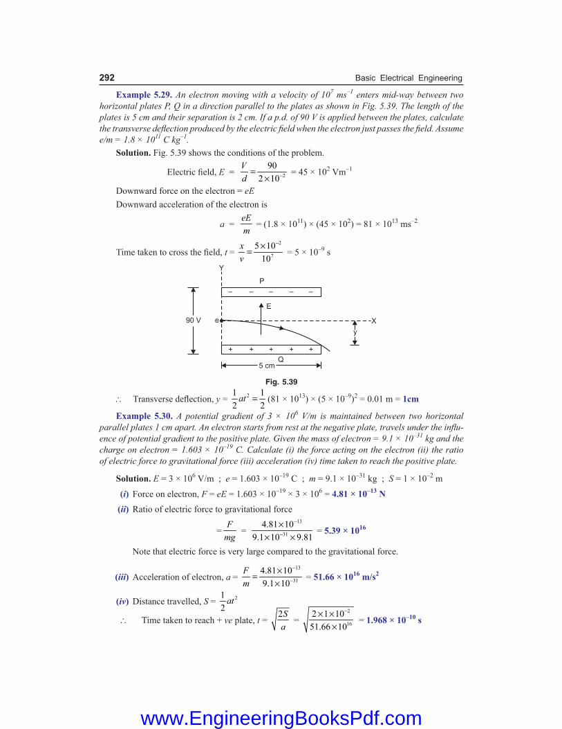
292 Basic Electrical Engineering
Example 5.29. An electron moving with a velocity of 107 ms–1 enters mid-way between two horizontal plates P, Q in a direction parallel to the plates as shown in Fig. 5.39. The length of the plates is 5 cm and their separation is 2 cm. If a p.d. of 90 V is applied between the plates, calculate the transverse deflection produced by the electric field when the electron just passes the field. Assume e/m = 1.8 × 10¹¹ C kg–1. Solution. Fig. 5.39 shows the conditions of the problem.
Electric field, E = 2
902 10
Vd −=
× = 45 × 102 Vm–1
Downward force on the electron = eE Downward acceleration of the electron is
a = eEm
= (1.8 × 1011) × (45 × 102) = 81 × 1013 ms–2
Time taken to cross the field, t = 2
7
5 1010
xv
−×= = 5 × 10⁻⁹ s
Fig. 5.39
\ Transverse deflection, y = 21 12 2
at = (81 × 1013) × (5 × 10–9)2 = 0.01 m = 1cm
Example 5.30. A potential gradient of 3 × 10⁶ V/m is maintained between two horizontal parallel plates 1 cm apart. An electron starts from rest at the negative plate, travels under the influ-ence of potential gradient to the positive plate. Given the mass of electron = 9.1 × 10⁻³¹ kg and the charge on electron = 1.603 × 10⁻¹⁹ C. Calculate (i) the force acting on the electron (ii) the ratio of electric force to gravitational force (iii) acceleration (iv) time taken to reach the positive plate.
Solution. E = 3 × 10⁶ V/m ; e = 1.603 × 10⁻¹⁹ C ; m = 9.1 × 10⁻³¹ kg ; S = 1 × 10⁻² m
(i) Force on electron, F = eE = 1.603 × 10–19 × 3 × 106 = 4.81 × 10⁻¹³ N (ii) Ratio of electric force to gravitational force
=F
mg =
13
31
4.81 109.1 10 9.81
−
−
×× ×
= 5.39 × 10¹⁶
Note that electric force is very large compared to the gravitational force.
(iii) Acceleration of electron, a = 13
31
4.81 109.1 10
Fm
−
−
×=×
= 51.66 × 10¹⁶ m/s2
(iv) Distance travelled, S = 212
at
\ Time taken to reach + ve plate, t = 2Sa
= 2
16
2 1 1051.66 10
−× ××
= 1.968 × 10⁻¹⁰ s
www.EngineeringBooksPdf.com
Electrostatics 293
Example 5.31. An electron of charge 1.6 × 10⁻¹⁹ C can move freely for a distance of 2 cm in a field of 1000 V/cm. The mass of the electron is 9.1 × 10⁻²⁸ g. If the electron starts with an initial velocity of zero, what velocity will it attain, what will be the time taken and what will be its kinetic energy? Solution. e = 1.6 × 10⁻¹⁹ C ; m = 9.1 × 10⁻³¹ kg ; E = 1000 V/cm = 105 V/m Distance of free movement, d = 2 cm = 0.02 m \ Potential difference applied, V = E × d = 105 × 0.02 volts Energy imparted to electron = Charge × P.D. = e × V = 1.6 × 10–19 × 105 × 0.02 = 3.2 × 10⁻¹⁶ J
Now, Energy imparted = K.E. of electron = 3.2 × 10⁻¹⁶ J
Also v = 2eVm
= 16
31
2 3.2 109.1 10
−
−
× ××
= 2.652 × 10⁷ m/s
Force on electron, F = eE = 1.6 × 10–19 × 105 = 1.6 × 10⁻¹⁴ N
Acceleration of electron, a = 14
31
1.6 109.1 10
Fm
−
−
×=×
= 1.758 × 10¹⁶ m/s2
Distance travelled, d = 212
at
\ Time taken, t = 2da
= 16
2 0.021.758 10
××
= 1.51 × 10⁻⁹ s
Objective Questions
1. The force between two electrons separated by a distance r varies as
(i) r2 (ii) r (iii) r−1 (iv) r−2
2. Two charges are placed at a certain distance apart. A brass sheet is placed between them. The force between them will
(i) increase (ii) decrease (iii) remain unchanged (iv) none of the above 3. Which of the following appliance will be stud-
ied under electrostatics ? (i) incandescent lamp (ii) electric iron (iii) lightning rod (iv) electric motor 4. The relative permittivity of air is (i) 0 (ii) 1 (iii) 8·854 × 10−12 (iv) none of the above 5. The relative permittivity of a material is 10. Its
absolute permittivity will be (i) 8·854 × 10−11 F/m (ii) 9 × 10⁸ F/m
(iii) 5 × 10⁻⁵ F/m (iv) 9 × 10⁵ F/m 6. Another name for relative permittivity is (i) dielectric constant (ii) dielectric strength (iii) potential gradient (iv) none of the above 7. The relative permittivity of most materials lies
between (i) 20 and 100 (ii) 10 and 20 (iii) 100 and 200 (iv) 1 and 10 8. When the relative permittivity of the medium
is increased, the force between two charges placed at a given distance apart
(i) increases (ii) decreases (iii) remains the same (iv) none of the above 9. Two charges are placed at a distance apart. If
a glass slab is placed between them, the force between the charges will
(i) be zero (ii) increase (iii) decrease (iv) remain the same
www.EngineeringBooksPdf.com

294 Basic Electrical Engineering
10. There are two charges of +1 µC and +5 µC. The ratio of the forces acting on them will be
(i) 1 : 1 (ii) 1 : 5 (iii) 5 : 1 (iv) 1 : 25 11. A soap bubble is given a negative charge. Its
radius (i) decreases (ii) increases (iii) remains unchanged (iv) information is incomplete to say anything 12. The ratio of force between two small spheres
with constant charge in air and in a medium of relative permittivity K is
(i) K2 : 1 (ii) 1 : K (iii) 1 : K2 (iv) K : 1 13. An electric field can deflect (i) x-rays (ii) neutrons (iii) α-particles (iv) γ-rays 14. Electric lines of force enter or leave a charged
surface at an angle (i) of 90º (ii) of 30º (iii) of 60º (iv) depending upon surface conditions 15. The relation between absolute permittivity of
vacuum (ε0), absolute permeability of vacuum (µ0) and velocity of light (c) in vacuum is
(i) µ0ε0 = c2 (ii) µ0/ε0 = c
(iii) ε0/µ0 = c (iv) 0 0
1µ ε
= c2
16. As one penetrates a uniformly charged sphere, the electric field strength E
(i) increases (ii) decreases (iii) is zero at all points (iv) remains the same as at the surface 17. If the relative permittivity of the medium in-
creases, the electric intensity at a point due to a given charge
(i) decreases (ii) increases (iii) remains the same (iv) none of the above 18. Electric lines of force about a negative point
charge are (i) circular, anticlockwise
(ii) circular, clockwise (iii) radial, inward (iv) radial, outward 19. A hollow sphere of charge does not produce an
electric field at any (i) outer point (ii) interior point (iii) beyond 2 m (iv) beyond 10 m 20. Two charged spheres of radii 10 cm and 15 cm
are connected by a thin wire. No current will flow if they have
(i) the same charge (ii) the same energy (iii) the same field on their surface (iv) the same potential 21. Electric potential is a (i) scalar quantity (ii) vector quantity (iii) dimensionless (iv) nothing can be said 22. A charge Q1 exerts some force on a second
charge Q2. A third charge Q3 is brought near. The force of Q1 exerted on Q2
(i) decreases (ii) increases (iii) remains unchanged (iv) increases if Q3 is of the same sign as Q1
and decreases if Q3 is of opposite sign 23. The potential at a point due to a charge is 9
V. If the distance is increased three times, the potential at that point will be
(i) 27 V (ii) 3 V (iii) 12 V (iv) 18 V 24. A hollow metal sphere of radius 5 cm is charged
such that the potential on its surface is 10 V. The potential at the centre of the sphere is
(i) 10 V (ii) 0 V (iii) same as at point 5 cm away from the sur-
face (iv) same as at point 25 cm away from the sur-
face 25. If a unit charge is taken from one point to an-
other over an equipotential surface, then, (i) work is done on the charge (ii) work is done by the charge (iii) work on the charge is constant (iv) no work is done
Answers 1. (iv) 2. (ii) 3. (iii) 4. (ii) 5. (i) 6. (i) 7. (iv) 8. (ii) 9. (iii) 10. (i) 11. (ii) 12. (iv) 13. (iii) 14. (i) 15. (iv) 16. (iii) 17. (i) 18. (iii) 19. (ii) 20. (iv) 21. (i) 22. (iii) 23. (ii) 24. (i) 25. (iv)
www.EngineeringBooksPdf.com

Introduction It is well known that different bodies hold different charge when given the same potential. This charge holding property of a body is called capacitance or capacity of the body. In order to store suf-ficient charge, a device called capacitor is purposely constructed. A capacitor essentially consists of two conducting surfaces (say metal plates) separated by an insulating material (e.g., air, mica, paper etc.). It has the property to store electrical energy in the form of electrostatic charge. The capaci-tor can be connected in a circuit so that this stored energy can be made to flow in a desired circuit to perform a useful function. Capacitance plays an important role in d.c. as well as a.c. circuits. In many circuits (e.g., radio and television circuits), capacitors are intentionally inserted to introduce the desired capacitance. In this chapter, we shall confine our attention to the role of capacitance in d.c. circuits only.
6.1. Capacitor Any two conducting surfaces separated by an insulating material is called a *capacitor or condenser. Its purpose is to store charge in a small space. The conducting surfaces are called the plates of the capacitor and the insulating material is called the **dielectric. The most commonly used dielectrics are air, mica, waxed paper, ceramics etc. The following points may be noted carefully : (i) The ability of a capacitor to store charge (i.e. its capacitance) depends upon the area of
plates, distance between plates and the nature of insulating material (or dielectric). (ii) A capacitor is generally named after the dielectric used e.g. air capacitor, paper capacitor,
mica capacitor etc. (iii) The capacitor may be in the form of parallel plates, concentric cylinder or other arrangement.
6.2. How does a Capacitor Store Charge ? Fig. 6.1 shows how a capacitor stores charge when connected to a d.c. supply. The parallel plate capacitor having plates A and B is connected across a battery of V volts as shown in Fig. 6.1 (i). When the switch S is open as shown in Fig. 6.1 (i), the capacitor plates are neutral i.e. there is no charge on the plates. When the switch is closed as shown in Fig. 6.1 (ii), the electrons from plate A will be attracted by the +ve terminal of the battery and these electrons start ***accumulating on plate B. The result is that plate A attains more and more positive charge and plate B gets more and more negative charge. This action is referred to as charging a capacitor because the capacitor plates are becoming charged. This process of electron flow or charging (i.e. detaching electrons from plate A and accumulating on B) continues till p.d. across capacitor plates becomes equal to battery voltage V. When the capacitor is charged to battery voltage V, the current flow ceases as shown in Fig. 6.1
* The name is derived from the fact that this arrangement has the capacity to store charge. The name con-denser is given to the device due to the fact that when p.d. is applied across it, the electric lines of force are condensed in the small space between the plates.
** A steady current cannot pass through an insulator but an electric field can. For this reason, an insulator is often referred to as a dielectric.
*** The electrons cannot flow from plate B to A as there is insulating material between the plates. Hence electrons detached from plate A start piling up on plate B.
6Capacitance and Capacitors
www.EngineeringBooksPdf.com

296 Basic Electrical Engineering
(iii). If now the switch is opened as shown in Fig. 6.1 (iv), the capacitor plates will retain the charges. Thus the capacitor plates which were neutral to start with now have charges on them. This shows that a capacitor stores charge. The following points may be noted about the action of a capacitor : (i) When a d.c. potential difference is applied across a capacitor, a charging current will flow
until the capacitor is fully charged when the current will cease. This whole charging process takes place in a very short time, a fraction of a second. Thus a capacitor once charged, prevents the flow of direct current.
(ii) The current does not flow through the capacitor i.e. between the plates. There is only transference of electrons from one plate to the other.
(iii) When a capacitor is charged, the two plates carry equal and opposite charges (say + Q and –Q). This is expected because one plate loses as many electrons as the other plate gains. Thus charge on a capacitor means charge on either plate.
Fig. 6.1
(iv) The energy required to charge the capacitor (i.e. transfer of electrons from one plate to the other) is supplied by the battery.
6.3. Capacitance The ability of a capacitor to store charge is known as its capacitance. It has been found experimentally that charge Q stored in a capacitor is directly proportional to the p.d. V across it i.e. Q ∝ V
or QV
= Constant = C
The constant C is called the capacitance of the capacitor. Hence capacitance of a capacitor can be defined as under : The ratio of charge on capacitor plates to the p.d. across the plates is called capacitance of the capacitor.
www.EngineeringBooksPdf.com

Capacitance and Capacitors 297
Unit of capacitance We know that : C = Q/VThe SI unit of charge is 1 coulomb and that of voltage is 1 volt. Therefore, the SI unit of capacitance is one coulomb/volt which is also called farad (Symbol F) in honour of Michael Faraday. 1 farad = 1 coulomb/volt A capacitor is said to have a capacitance of 1 farad if a charge of 1 coulomb accumulates on each plate when a p.d. of 1 volt is applied across the plates. Thus if a charge of 0·1C accumulates on each plate of a capacitor when a p.d. of 10V is applied across its plates, then capacitance of the capacitor = 0·1/10 = 0·01 F. The farad is an extremely large unit of capacitance. Practical capacitors have capacitances of the order of microfarad (µF) and micro-microfarad (µµF) or picofarad (pF). 1 µF = 10−6F ; 1µµF (or 1 pF) = 10−12 F
6.4. Factors Affecting Capacitance The ability of a capacitor to store charge (i.e. its capacitance) depends upon the following factors : (i) Area of plate. The greater the area of capacitor plates, the larger is the capacitance of the
capacitor and vice-versa. It is because larger the plates, the greater the charge they can hold for a given p.d. and hence greater will be the capacitance.
(ii) Thickness of dielectric. The capacitance of a capacitor is inversely proportional to the thickness (i.e. distance between plates) of the dielectric. The smaller the thickness of dielectric, the greater the capacitance and vice-versa. When the plates are brought closer, the electrostatic field is intensified and hence capacitance increases.
(iii) Relative permittivity of dielectric. The greater the relative permittivity of the insulating material (i.e., dielectric), the greater will be the capacitance of the capacitor and vice-versa. It is because the nature of dielectric affects the electrostatic field between the plates and hence the charge that accumulates on the plates.
6.5. Dielectric Constant or Relative Permittivity The insulating material between the plates of a capacitor is called dielectric. When the capacitor is charged, the electrostatic field extends across the dielectric. The presence of dielectric* increases the concentration of electric lines of force between the plates and hence the charge on each plate. The degree of concentration of electric lines of force between the plates depends upon the nature of dielectric. The ability of a dielectric material to concentrate electric lines of force between the plates of a capacitor is called dielectric constant or relative permittivity of the material. Air has been assigned a reference value of dielectric constant (or relative permittivity) as 1. The dielectric constant of all other insulating materials is greater than unity. The dielectric constants of materials commonly used in capacitors range from 1 to 10. For example, dielectric constant of mica is 6. It means that if mica is used as a dielectric between the plates of a capacitor, the charge on each plate will be 6 times the value when air is used; other things remaining equal. In other words, with mica as dielectric, the capacitance of the capacitor becomes 6 times as great as when air is used.
* Normally, the electrons of the atoms of the dielectric revolve around their nuclei in their regular orbits. When the capacitor is charged, electrostatic field causes distortion of the orbits of the electrons of the dielectric. This distortion of orbits causes an additional electrostatic field within the dielectric which causes more electrons to be transferred from one plate to the other. Hence, the presence of dielectric increases the charge on the capacitor plates and hence the capacitance.
www.EngineeringBooksPdf.com

298 Basic Electrical Engineering
Let V = Potential difference between capacitor plates Q = Charge on capacitor when air is dielectric Then, Cair = Q/V When mica is used as a dielectric in the capacitor and the same p.d. is applied, the capacitor will now hold a charge of 6Q.
\ Cmica = 6
6Q Q
V V= = 6 Cair
or mica
air
CC
= 6 = Dielectric constant of mica
Hence dielectric constant (or relative permittivity) of a dielectric material is the ratio of capacitance of a capacitor with that material as a dielectric to the capacitance of the same capacitor with air as dielectric.
6.6. Capacitance of an Isolated Conducting Sphere We can find the capacitance of an isolated spherical conductor by assuming that “missing” plate is earth (zero potential). Suppose an isolated conducting sphere of radius r is placed in a medium of rela-tive permittivity er as shown in Fig. 6.2. Let charge +Q be given to this spherical conductor. The charge is spread *uniformly over the surface of the sphere. Therefore, in order to find the potential at any point on the surface of sphere (or outside the sphere), we can assume that entire charge + Q is concentrated at the centre O of the sphere.
Potential at the surface of the sphere, V = 04 r
Qrπε ε
\ Capacitance of isolated sphere, C = QV
= 4pe0er r
\ **C = 4π ε0 εr r ... in a medium = 4π ε0 r ... in air The following points may be noted : (i) The capacitance of an isolated spherical conductor is directly proportional to its radius.
Therefore, for a given potential, a large spherical conductor (more r) will hold more charge Q (= CV) than the smaller one.
(ii) Unit of ε0 = C/4πr = F/m. Hence, the SI unit of ε0 is F/m. Example 6.1. Twenty seven spherical drops, each of radius 3 mm and carrying 10–12 C of charge are combined to form a single drop. Find the capacitance and potential of the bigger drop. Solution. Let r and R be the radii of smaller and bigger drops respectively. Volume of bigger drop = 27 × Volume of smaller drop
or 34
3Rπ = 34
273
r× π
or R = 3r = 3 × 3 = 9 mm = 9 × 10⁻³ m
Capacitance of bigger drop, C = 4π ε0 R = 39
19 10
9 10−× ×
× = 10–12 F = 1 pF
* Note that a charged conductor is an equipotential surface. Therefore, electric lines of force emerging from the sphere are everywhere normal to the sphere.
** Note that values of Q and V do not occur in the expression for capacitance. This again reminds us that capacitance is a property of physical construction of a capacitor.
Fig. 6.2
www.EngineeringBooksPdf.com

Capacitance and Capacitors 299
Since charge is conserved, the charge on the bigger drop is 27 × 10–12 C.
\ Potential of bigger drop, V = 12
12
27 10
10
QC
−
−
×= = 27 V
6.7. Capacitance of Spherical Capacitor We shall discuss two cases. (i) When outer sphere is earthed. A spherical capacitor consists of two concentric hollow
metallic spheres A and B which do not touch each other as shown in Fig. 6.3. The outer sphere B is earthed while charge is given to the inner sphere A. Suppose the medium between the two spheres has relative permittivity εr.
Let rA = radius of inner sphere A rB = radius of outer sphere B When a charge +Q is given to the inner sphere A, it induces a charge –Q on the inner surface of outer sphere B and +Q on the outer surface of B. Since sphere B is earthed, +Q charge on its outer surface is neutralised by earth.
*Potential at inner sphere A, VA = 0 04 4r A r B
QQr r
− + πε ε πε ε
= 0 0
( )1 14 4
B A
r A B r A B
Q r rQr r r r
− − = π ε ε π ε ε Since sphere B is earthed, its potential is zero (i.e., VB = 0). \ P.D. between A and B, VAB = VA – VB = VA – 0 = VA
\ Capacitance of spherical capacitor, C = A
QV
= 04( )
r A B
B A
r rr r
π ε ε−
\ C = 04( )
r A B
B A
r rr r
π ε ε− ... in a medium
= 04( )
A B
B A
r rr r
π ε− ... in air
(ii) When inner sphere is earthed. Fig. 6.4 shows the situation. The system constitutes two capacitors in parallel.
(a) One capacitor (CBA) consists of the inner surface of B and outer surface of A. Its capacitance as found above is
CBA = 04 r A B
B A
r rr r
π ε ε−
(b) The second capacitor (CBG) consists of outer surface of B and earth. Its capacitance is that of an isolated sphere.
\ CBG = 4π ε0 rB … if surrounding medium is air \ Total capacitance = CBA + CBG
Note. Unless stated otherwise, the outer sphere of a spherical capacitor is assumed to be earthed.
Fig. 6.3
* Potential on sphere A = (Potential on sphere A due to its own charge +Q) + (Potential on sphere A due to
charge –Q on sphere B) = 0 04 4r A r B
Q Qr r
−+ π ε ε π ε ε
Fig. 6.4
www.EngineeringBooksPdf.com

300 Basic Electrical Engineering
Example 6.2. The thickness of air layer between two coatings of a spherical capacitor is 2 cm. The capacitor has the same capacitance as the capacitance of sphere of 1.2 m diameter. Find the radii of its surfaces. Solution. Given : 04 A B
B A
r rr rπ ε
− = 4π ε0 R \ A B
B A
r rr r− = R
Here, rB – rA = 2 cm and R = 1·2/2 = 0·6 m = 60 cm
\ 2
A Br r = 60 or rA rB = 120
Now (rB + rA)2 = (rB – rA)2 + 4rA rB = (2)2 + 4 × 120 = 484
\ rB + rA = 484 = 22 cm
Since rB – rA = 2 cm and rB + rA = 22 cm, rB = 12 cm ; rA = 10 cm Example 6.3. A capacitor has two concentric thin spherical shells of radii 8 cm and 10 cm. The outer shell is earthed and a charge is given to the inner shell. Calculate (i) the capacitance of this capacitor and (ii) the final potential acquired by the inner shell if the outer shell is removed after the inner shell has acquired a potential of 200 V. Solution. It is assumed that medium between the two spherical shells is air so that er = 1. (i) Radius of inner sphere, rA = 8 cm = 0.08 m; Radius of outer sphere, rB = 10 cm = 0.1 m
The capacitance C of the spherical capacitor is
C = 04 r A B
B A
r rr r
πε ε− =
124 8.854 10 0.08 0.10.1 0.08
−π × × × ×− = 44.44 × 10⁻¹² F
(ii) Charge on the capacitor when the inner sphere acquires a potential of 200 V is Q = CV = 44.44 × 10–12 × 200 = 8888 × 10–12 C When the outer shell is removed, the capacitance C′ of the resulting isolated sphere is
C′ = 4pe0er rA = 91 1 0.08
9 10× ×
× = 8.88 × 10⁻¹² F
\ Potential V ′ acquired by the inner shell when outer shell is removed is
V′ = QC′ =
12
12
8888 10
8.88 10
−
−××
= 1000 V
Tutorial Problems 1. Calculate the capacitance of a conducting sphere of radius 10 cm situated in air. How much charge is
required to raise it to a potential of 1000 V? [11 pF; 1.1 × 10⁻⁸ C] 2. When 1.0 × 10¹² electrons are transferred from one conductor to another of a capacitor, a potential dif-
ference of 10V develops between the two conductors. Calculate the capacitance of the capacitor. [1.6 × 10⁻⁸ F] 3. Calculate the capacitance of a spherical capacitor if the diameter of inner sphere is 0.2 m and that of the
outer sphere is 0.3 m, the space between them being filled with a liquid having dielectric constant 12. [4 × 10⁻¹⁰ F] 4. The stratosphere acts as a conducting layer for the earth. If the stratosphere extends beyond 50 km
from the surface of the earth, then calculate the capacitance of the spherical capacitor formed between stratosphere and earth’s surface. Take radius of earth as 6400 km. [0.092 F]
5. A spherical capacitor has an outer sphere of radius 0.15 m and the inner sphere of radius 0.1m. The outer sphere is earthed and inner sphere is given a charge of 6µC. The space between the concentric spheres is filled with a material of dielectric constant 18. Calculate the capacitance and potential of the inner sphere. [6 × 10⁻¹⁰ F; 104 V]
www.EngineeringBooksPdf.com

Capacitance and Capacitors 301
6.8. Capacitance of Parallel-Plate Capacitor with Uniform Medium We have seen that the capacitance of a capacitor can be determined from its electrical properties using the relation C = Q/V. However, it is often desirable to determine the capacitance of a capacitor in terms of its dimensions and relative permittivity of the dielectric. Although there are many forms of capacitors, the most important arrangement is the parallel-plate capacitor. Consider a parallel plate capacitor consisting of two plates, each of area A square metres and separated by a uniform dielectric of thickness d metres and relative permittivity εr as shown in Fig. 6.5. Let a p.d. of V volts applied between the plates place a charge of +Q and − Q on the plates. With reasonable accuracy, it can be assumed that electric field between the plates is uniform. Electric flux density between plates is D = Q/A coulomb/m2
Electric intensity between plates is E = V/d But D = ε0 εr E ...See Art. 5.12
or QA
= 0 rVd
ε ε
or QV = 0 r A
dε ε
The ratio Q/V is the capacitance C of the capacitor.
\ C = 0 r Ad
ε ε ...in a medium
= 0 Ad
ε ...in air
The following points may be noted carefully : (i) Capacitance is directly proportional to εr and A and inversely proportional to d.
(ii) medr
air
CC
= ε = Relative permittivity of medium
(iii) Re-arranging the relation for C in air
ε0 = 2
farad × m
m
CdA
= = F/m
Obviously, permittivity can also be measured in F/m.
6.9. Parallel-Plate Capacitor with Composite Medium Suppose the space between the plates is occupied by three dielectrics of thicknesses d1, d2 and d3 metres and relative permittivities εr1, εr2 and εr3 respectively as shown in Fig. 6.6. The electric flux density D in the dielectrics remains the *same and is equal to Q/A. However, the electric intensities in the three dielectrics will be different and are given by ;
E1 = 2 30 1 0 2 0 3
; ;r r r
D D DE E= =ε ε ε ε ε ε
If V is the total p.d. across the capacitor and V1, V2 and V3 the p.d.s. across the three dielectrics respectively, then, V = V1 + V2 + V3
= E1 d1 + E2 d2 + E3 d3
Fig. 6.5
* The total charge on each plate is Q. Hence Q coulombs is also the total electric flux through each dielectric.
www.EngineeringBooksPdf.com

302 Basic Electrical Engineering
= 1 2 30 1 0 2 0 3r r r
D D Dd d d+ +ε ε ε ε ε ε
= 31 2
0 1 2 3r r r
dd dD + + ε ε ε ε
= 31 2
0 1 2 3r r r
dd dQA
+ + ε ε ε ε ( )QD
A=∵
or QV = 0
31 2
1 2 3r r r
Add d
ε + + ε ε ε
But Q/V is the capacitance C of the capacitor.
\ C = 0
31 2
1 2 3
farad
r r r
Add d
ε + + ε ε ε
In general,
C = 0 farad
r
Ad
ε
ε∑ ...(i)
Different cases. We shall discuss the following two cases : (i) Medium partly air. Fig. 6.7 shows a parallel plate capacitor having plates d metres apart.
Suppose the medium between the plates consists partly of air and partly of dielectric of thickness t metres and relative permittivity εr2. Then thickness of air is d − t. Using the relation (i) above, we have,
Fig. 6.7 Fig. 6.8
C = 0
21 r
Ad t t
ε− +
ε
= 0
2
farad
r
Atd t
ε − − ε
(ii) When dielectric slab introduced. Fig. 6.8 shows a parallel-plate air capacitor having plates d metres apart. Suppose a dielectric slab of thickness t metres and relative permittivity εr2 is introduced between the plates of the capacitor.
Using the relation (i) above, we have,
C = 0
21 r
Ad t t
ε− +
ε
= 0
2
farad
r
Atd t
ε − − ε
Fig. 6.6
www.EngineeringBooksPdf.com

Capacitance and Capacitors 303
6.10. Special Cases of Parallel-Plate Capacitor We have seen that capacitance of a capacitor depends upon plate area, thickness of dielectric and value of relative permittivity of the dielectric. We consider two cases by way of illustration. (i) Fig. 6.9 shows that dielectric thickness is d but plate area is divided into two parts; area
A1 having air as the dielectric and area A2 having dielectric of relative permittivity εr. The arrangement is equivalent to two capacitors in parallel. Their capacitances are :
C1 = 0 1Ad
ε ; C2 = 0 2r A
dε ε
The total capacitance C of this parallel-plate capacitor is
C = C1 + C2
(ii) Fig. 6.10 shows that plate area is divided into two parts ; area A1 has dielectric (air) of thickness d and area A2 has a dielectric (εr) of thickness t and the remaining thickness is occupied by air. The arrangement is equivalent to two capacitors connected in parallel. Their capacitances are :
C1 = 0 1Ad
ε ; C2 = 0 2
[ ( / )]r
Ad t t
ε− − ε
The total capacitance C of this parallel plate capacitor is C = C1 + C2
6.11. Multiplate Capacitor The most *convenient way of achieving large capacitance is by using large plate area. Increasing the plate area may increase the physical size of the capacitor enormously. In order to obtain a large area of plate surface without using too bulky a capacitor, multiplate construction is employed. In this construction, the capacitor is built up of alternate sheets of metal foil (i.e. plates) and thin sheets of dielectric. The odd-numbered metal sheets are connected together to form one terminal T1 and even-numbered metal sheets are connected together to form the second terminal T2. Fig. 6.11 shows a multiplate capacitor with seven plates. A little
Fig. 6.9 Fig. 6.10
Fig. 6.11
* The capacitance of a capacitor can also be increased by (i) using a dielectric of high er and (ii) decreasing the distance between plates. High cost limits the choice of dielectric and dielectric strength of the insulating material limits the reduction in spacing between the plates..
www.EngineeringBooksPdf.com

304 Basic Electrical Engineering
reflection shows that this arrangement is equivalent to 6 capacitors in parallel. The total capacitance will, therefore, be 6 times the capacitance of a single capacitor (formed by say plates 1 and 2). If there are n plates, each of area A, then (n − 1) capacitors will be in parallel. \ Capacitance of n plate capacitor is
C = 0( 1) r And
ε ε−
where d is the distance between any two adjacent plates and εr is the relative permittivity of the medium. It may be seen that plate area is increased from A to A (n − 1). Variable Air capacitor. It is a multiplate air capacitor whose capacitance can be varied by changing the plate area. Fig. 6.12 shows a variable air capacitor commonly used to “tune in” radio stations in the radio receiver. It consists of a set of stationary metal plates Y fixed to the frame and another set of movable metal plates X fixed to the central shaft. The two sets of plates are electrically insulated from each other. Rotation of the shaft moves the plates X into the spaces between plates Y, thus changing the *common (or effective) plate area and hence the capacitance. The capacitance of such a capacitor is given by ;
C = 0( 1)An
dε− ( εr = 1)
When the movable plates X are completely rotated in (i.e. the two sets of plates completely over-lap each other), the common plate area ‘A’ is maximum and so is the capacitance of the capacitor. Minimum capacitance is obtained when the movable plates X are completely rotated out of station-ary plates Y. The capacitance of such variable capacitors is from zero to about 4000 pF. Note. In all the formulas derived for capacitance, capacitance will be in farad if area is in m2 and the dis-tance between plates is in m. Example 6.4. A p.d. of 10 kV is applied to the terminals of a capacitor consisting of two paral-lel plates, each having an area of 0·01 m2 separated by a dielectric 1 mm thick. The resulting ca-pacitance of the arrangement is 300 pF. Calculate (i) total electric flux (ii) electric flux density (iii) potential gradient and (iv) relative permittivity of the dielectric.
Solution. C = 300 × 10−12 F ; V = 10 × 103 = 104 volts (i) Total electric flux, Q = C V = (300 × 10−12) × 104 = 3 × 10⁻⁶ C = 3µC
(ii) Electric flux density, D = 63 10
0 01QA
−×=⋅ = 3 × 10⁻⁴ C/m2
(iii) Potential gradient = 4
310
1 10
Vd −=
× = 107 V/m
(iv) Now, E = 107 V/m
Since D = ε0εr E
\ εr = 4
12 70
3 10
(8.854 10 ) 10
DE
−
−×=
ε × × = 3·39
Fig. 6.12
* Remember in the formula for capacitance, A is the common plate area i.e. plate area facing the opposite polarity plate area.
www.EngineeringBooksPdf.com

Capacitance and Capacitors 305
Example. 6.5. A capacitor is composed of two plates separated by 3mm of dielectric of per-mittivity 4. An additional piece of insulation 5mm thick is now inserted between the plates. If the capacitor now has capacitance one-third of its original capacitance, find the relative permittivity of the additional dielectric. Solution. Figs. 6.13 (i) and 6.13 (ii) respectively show the two cases.
For the first case, C = 0 1 03
4
3 10r A A
d −ε ε ε × ×=
× ...(i)
For the second case, 3C = 0
1 2
1 2r r
Ad d
ε
+ε ε
= 03 3
2
3 10 5 104 r
A− −ε
× ×+ε
...(ii)
Fig. 6.13 Dividing eq. (i) by eq. (ii), we get,
3 = 2
4 3 53 4 r
+ ε or 9 = 3 + 20/εr2 \ εr2 = 20/6 = 3·33 Example 6.6. Determine the dielectric flux in microcoulombs between two parallel plates each 0.35 metre square with an air gap of 1.5 mm between them, the p. d. being 3000 V. A sheet of insulating material 1 mm thick is inserted between the plates, the relative permittivity of the insulating material being 6. Find out the potential gradient in the insulating material and also in air if the voltage across the plates is raised to 7500 V. Solution. A = 0.35 × 0.35 = 0.1225 m2 ; d = 1.5 mm = 1.5 × 10⁻³ m ; er = 1(air). Capacitance C of the parallel-plate air capacitor is
C = 0 r Ad
ε ε =
12
3
8.854 10 1 0.1225
1.5 10
−
−× × ×
× = 723 × 10–12 F
Dielectric flux, ψ = Q = CV = 723 × 10–12 × 3000 = 2.17 × 10⁻⁶ C = 2.17 µC Suppose the potential gradient in air is ga. Then potential gradient in the insulating material is gi = ga/er = ga/6. Thickness of air ; ta = 1.5 – 1 = 0.5 mm = 0.5 × 10⁻³ m ; Thickness of insulating material, ti = 1mm = 10–3 m. \ Applied voltage, V = gata + giti
www.EngineeringBooksPdf.com

306 Basic Electrical Engineering
or 7500 = ga × 0.5 × 10⁻³ + 6ag
× 10–3
\ ga = 11.25 × 10⁶ V/m
and gi = 6ag
= 611.25 10
6×
= 1.875 × 10⁶ V/m
Example 6.7. An air capacitor has two parallel plates of 1500 cm2 in area and 5 mm apart. If a dielectric slab of area 1500 cm2, thickness 2 mm and relative permittivity 3 is now introduced between the plates, what must be the new separation between the plates to bring the capacitance to the original value? Solution. This is a case of introduction of dielectric slab into an air capacitor. As proved in Art. 6.9, the capacitance under this condition becomes :
C = 0
( / )r
Ad t t
ε− − ε ...(i)
If the medium were totally air, capacitance would have been
Cair = 0 Ad
ε ...(ii)
Inspection of eqs. (i) and (ii) shows that with the introduction of dielectric slab between the plates of air capacitor, its capacitance increases. The distance between the plates is effectively reduced by t − (t/εr). In order to bring the capacitance to the original value, the plates must be separated by this much distance in air. \ New separation between the plates = d + (t − t/εr) = 5 + (2 − 2/3) = 6·33 mm Example 6.8. A variable air capacitor has 11 movable plates and 12 stationary plates. The area of each plate is 0·0015 m2 and separation between opposite plates is 0·001 m. Determine the maximum capacitance of this variable capacitor. Solution. The capacitance will be maximum when the movable plates are completely rotated in i.e. when the two sets of plates completely overlap each other. Under this condition, the common (or effective) area is equal to the physical area of each plate.
C = 0( 1) r And
ε ε−
Here n = 11 + 12 = 23 ; εr = 1 ; A = 0·0015 m2 ; d = 0·001 m
\ C = 128.854 10 1 0.0015
(23 1)0.001
−× × ×− × = 292 × 10−12F = 292 pF
Example 6.9. The capacitance of a variable radio capacitor can be changed from 50 pF to 950 pF by turning the dial from 0º to 180º. With dial set at 180º, the capacitor is connected to 400 V bat-tery. After charging, the capacitor is disconnected from the battery and the dial is tuned at 0º. What is the potential difference across the capacitor when the dial reads 0º ? Solution. With dial at 0º, the capacitance of the capacitor is C1 = 50 pF = 50 × 10–12 F With dial at 180º, the capacitance of the capacitor is C2 = 950 pF = 950 × 10–12 F P.D. across C2, V2 = 400 V \ Charge on C2, Q = C2V2 = (950 × 10–12) × 400 = 380 × 10–9 C When the battery is disconnected, charge Q remains the same. Suppose V1 is the potential dif-ference across the capacitor when the dial reads 0º. \ Q = C1V1
www.EngineeringBooksPdf.com

Capacitance and Capacitors 307
or V1 = 9
121
380 10
50 10
QC
−
−×=
× = 7600 V
Example 6.10. A parallel plate capacitor has plates of area 2 m2 spaced by three layers of dif-ferent dielectric materials. The relative permittivities are 2, 4, 6 and thicknesses are 0.5, 1.5 and 0.3 mm respectively. Calculate the combined capacitance and the electric stress (potential gradient) in each material when applied voltage is 1000 V.
Solution. Capacitance, C = 0
31 2
1 2 3r r r
Add d
ε
+ +ε ε ε
= 12
3 3 38 854 10 2
0 5 10 1 5 10 0 3 102 4 6
−
− − −⋅ × ×
⋅ × ⋅ × ⋅ ×+ + = 0·0262 × 10–6 F
Charge on each plate, Q = CV = (0·0262 × 10–6) × 1000 = 26·2 × 10–6 C
Electric flux density, D = 626 2 10
2QA
−⋅ ×= = 13·1 × 10–6 C/m2
Electric stress in the material with εr1 = 2 is
E1 = 6
120 1
13 1 10
8 854 10 2r
D −
−⋅ ×=
ε ε ⋅ × × = 74 × 104 V/m
Electric stress in the material with εr2 = 4 is
E2 = 6
1213 1 10
8.854 10 4
−
−⋅ ×× ×
= 37 × 104 V/m
Electric stress in the material with εr3 = 6 is
E3 = 6
1213 1 10
8·854 10 6
−
−⋅ ×× ×
= 24.67 × 10⁴ V/m
It is clear from the above example that electric stress is greatest in the material having the least relative permittivity. Since air has the lowest relative permittivity, efforts should be made to avoid air pockets in the dielectric materials. Example 6.11. A parallel plate capacitor is maintained at a certain potential difference. When a 3 mm slab is introduced between the plates in order to maintain the same potential difference, the distance between the plates is increased by 2·4 mm. Find the dielectric constant of the slab. Solution. The capacitance of parallel-plate capacitor in air is
C = 0 Ad
ε ...(i)
With the introduction of slab of thickness t, the new capacitance is
C ′ = 0
(1 1/ )r
Ad t
ε′ − − ε ...(ii)
Now the charge (Q = CV) remains the same in the two cases.
\ 0 Ad
ε = 0
(1 1/ )r
Ad t
ε′ − − ε
or d = d ′ – t(1 – 1/εr) Here, d ′ = d + 2·4 × 10–3 m ; t = 3 mm = 3 × 10⁻³ m
\ d = d + 2·4 × 10–3 – 3 × 10⁻³ 11r
− ε or 2·4 × 10–3 = 3 × 10⁻³ 11
r
− ε \ εr = 5
www.EngineeringBooksPdf.com

308 Basic Electrical Engineering
Example 6.12. A parallel plate capacitor has three similar parallel plates. Find the ratio of capacitance when the inner plate is mid-way between the outers to the capacitance when inner plate is three times as near one plate as the other. Solution. Fig. 6.14 (i) shows the condition when the inner plate is mid-way between the outer plates. This arrangement is equivalent to two capacitors in parallel.
\ Capacitance of the capacitor C1 = 0 0 04/2 /2r r rA A A
d d dε ε ε ε ε ε+ =
Fig. 6.14 Fig. 6.14 (ii) shows the condition when inner plate is three times as near as one plate as the other.
\ Capacitance of the capacitor C2 = 0 0 016/4 3 /4 3r r rA A A
d d dε ε ε ε ε ε+ =
\ C1/C2 = 0.75 Example 6.13. The permittivity of the dielectric material between the plates of a parallel-plate capacitor varies uniformly from e1 at one plate to e2 at other plate. Show that the capacitance is given by ;
C = 2 1
2 1loge
Ad
ε − εε ε
where A and d are the area of each plate and separation between the plates respectively. Solution. Fig. 6.15 shows the conditions of the problem. The permittiv-ity of the dielectric material at a distance x from the left plate is
ex = 1 2 1( )xd
ε + ε − ε
Consider an elementary strip of width dx at a distance x from the left plate. The capacitance C of this strip is
C = x Adx
ε
or 1C =
x
dxAε =
1 2 1( )
dxxAd
ε + ε − ε
= 1 2 1( )
d dxA d xε + ε − ε
\ Total capacitance CT between the plates is
*1
TC = 0
1x d
xC
=
=∫ =
1 2 10
( )
dd dxA d xε + ε − ε∫
= ** 1 2 1
2 1 0
log ( ) d
e d xdA
ε + ε − ε ε − ε
Fig. 6.15
* The arrangement constitutes capacitors in series.
** log ( )e a bxdx
a bx b+=
+∫
www.EngineeringBooksPdf.com

Capacitance and Capacitors 309
= 1 2 1 12 1
[log ( ) log ]( ) e e
d d d d dA
ε + ε − ε − εε − ε
= 2 2
2 1 1 2 1 1log log
( ) ( )e edd d
A d Aε ε=
ε − ε ε ε − ε ε
\ CT = 2 1
2
1loge
Ad
ε − εεε
Tutorial Problems 1. A capacitor consisting of two parallel plates 0·5 mm apart in air and each of effective area 500 cm2 is
connected to a 100V battery. Calculate (i) the capacitance and (ii) the charge. [(i) 885 pF (ii) 0·0885 µC] 2. A capacitor consisting of two parallel plates in air, each of effective area 50 cm2 and 1 mm apart, carries
a charge of 1770 × 10−12 C. Calculate the p.d. between the plates. If the distance between the plates is increased to 5mm, what will be the electrical effect ? [40 V ; p.d. across plates is increased to 200 V]
3. Two insulated parallel plates each of 600 cm2 effective area and 5 mm apart in air are charged to a p.d. of 1000 V. Calculate (i) the capacitance and (ii) the charge on each plate.
The source of supply is now disconnected, the plates remaining insulated. Calculate (iii) the p.d. between the plates when their spacing is increased to 10 mm and (iv) the p.d. when the plates, still 10 mm apart, are immersed in oil of relative permittivity 5. [(i) 106·2 pF (ii) 106·2 × 10−12 C (iii) 2000 V (iv) 400 V]
4. A p.d. of 500 V is applied across a parallel plate capacitor with a plate area of 0·025 m2. The plates are separated by a dielectric of relative permittivity 2·5. If the capacitance of the capacitor is 500 µF, find (i) the electric flux (ii) electric flux density and (iii) the electric intensity.
[(i) 0·25 µC (ii) 0·01 mC/m2 (iii) 45.3 × 10⁶ V/m] 5. A capacitor consists of two parallel metal plates, each of area 2000 cm2 and 5 mm apart. The space be-
tween the plates is filled with a layer of paper 2 mm thick and a sheet of glass 3 mm thick. The relative permittivities of paper and glass are 2 and 8 respectively. A p.d. of 5 kV is applied across the plates. Calculate (i) the capacitance of the capacitor and (ii) the potential gradient in each dielectric.
[(i) 1290 pF (ii) 1820 V/mm (paper); 453 V/mm (glass)] 6. A parallel plate capacitor has a plate area of 20 cm2 and the plates are separated by three dielectric layers
each 1 mm thick and of relative permittivity 2, 4 and 5 respectively. Find the capacitance of the capacitor and the electric stress in each dielectric if applied voltage is 1000 V.
[18·6 pF ; 5·26 × 105 V/m; 2·63 × 105 V/m; 2·11 × 105 V/m] 7. A 1µF parallel plate capacitor that can just withstand a p.d. of 6000 V uses a dielectric having a relative
permittivity 5, which breaks down if the electric intensity exceeds 30 × 106 V/m. Find (i) the thickness of dielectric required and (ii) the effective area of each plate. [(i) 0·2 mm (ii) 4·5 m2]
8. An air capacitor has two parallel plates 10 cm2 in area and 5 mm apart. When a dielectric slab of area 10 cm2 and thickness 5 mm was inserted between the plates, one of the plates has to be moved by 0·4 cm to restore the capacitance. What is the dielectric constant of the slab ? [5]
9. A multiplate parallel capacitor has 6 fixed plates connected in parallel, interleaved with 5 similar plates; each plate has effective area of 120 cm2. The gap between the adjacent plates is 1 mm. The capacitor is immersed in oil of relative permittivity 5. Calculate the capacitance. [5·31 pF]
10. Calculate the number of sheets of tin foil and mica for a capacitor of 0·33 µF capacitance if area of each sheet of tin foil is 82 cm2, the mica sheets are 0·2 mm thick and have relative permittivity 5. [182 sheets of mica; 183 sheets of tin foil]
6.12. Cylindrical Capacitor A cylindrical capacitor consists of two co-axial cylinders separated by an insulating medium. This is an important practical case since a single core cable is in effect a capacitor of this kind. The conductor (or core) of the cable is the inner cylinder while the outer cylinder is represented by lead sheath which is at earth potential. The two co-axial cylinders have insulation between them.
www.EngineeringBooksPdf.com

310 Basic Electrical Engineering
Consider a single core cable with conductor diameter d metres and inner sheath diameter D metres (See Fig. 6.16). Let the charge per metre axial length of the cable be Q coulombs and εr be the relative permittivity of the insulating material. Consider a cylinder of radius x metres. According to Gauss’s theorem, electric flux passing through this cylinder is Q coulombs. The surface area of this cylinder is
= 2πx × 1 = 2πx m2
\ Electric flux density at any point P on the considered cylinder is given by ; Dx =
2Q
xπ C/m2
Electric intensity at point P is given by;
Ex = 0 02
x
r r
D Qx
=ε ε π ε ε V/m
The work done in moving a unit positive charge from point P through a distance dx in the direc-tion of electric field is Ex dx. Hence the work done in moving a unit positive charge from conductor to sheath, which is the p.d. V between the conductor and sheath, is given by ;
V = /2 /2
0 0/2 /2
log2 2
D D
x er rd d
Q Q DE dx dxx d
= =π ε ε πε ε∫ ∫
\ Capacitance of cable, C = 0
0
2F/m F/m
log ( / )log2
r
ee
r
Q QQV D dD
d
πε ε= =
πε ε
= 12
9
10 10
2 8 854 10F/m 10 F/m
2 303 log ( / ) 41 4 log ( / )r r
D d D d
−−π× ⋅ × × ε ε= ×
⋅ ⋅ If the cable has a length of l metres, then capacitance of the cable is
= 9
10 10
2410 F pF
41 4log ( / ) log ( / )r rl l
D d D d−ε ε× =
⋅ Example 6.14. In a concentric cable 20 cm long, the diameter of inner and outer cylinders are 15 cm and 15·4 cm respectively. The relative permittivity of the insulation is 5. If a p.d. of 5000 V is maintained between the two cylinders, calculate : (i) capacitance of cylindrical capacitor (ii) the charge (iii) the electric flux density and electric intensity in the dielectric. Solution. (i) Capacitance of the cylindrical capacitor is
C = 9 9
10 10
5 0 210 10 F41 4 log ( / ) 41 4 log (15 4 /15)
r lD d
− −ε × ⋅× = ×⋅ ⋅ ⋅ = 2.11 × 10⁻⁹ F
(ii) Charge on capacitor, Q = CV = (2·11 × 10–9) × 5000 = 10·55 × 10–6 C = 10·55 µC
(iii) To determine D and E in the dielectric, we shall consider the average radius of dielectric, i.e.,
Average radius of dielectric, x = 15 41 15
2 2 2⋅ + = 7·6 cm = 0·076 m
Fig. 6.16
www.EngineeringBooksPdf.com

Capacitance and Capacitors 311
Flux density in dielectric, D = 6
2 10 55 10C/m2 2 0 076 0 2
Qxl
−⋅ ×=π π× ⋅ × ⋅ = 110·47 × 10–6 C/m2
Electric intensity in dielectric, E = 6
120
110 47 10
8 854 10 5r
D −
−⋅ ×=
ε ε ⋅ × × = 2.5 × 10⁶ V/m
Example 6.15. A 33 kV, 50 Hz, 3-phase underground cable, 4 km long uses three single core cables. Each of the conductor has a diameter of 2·5 cm and the radial thickness of insulation is 0·5 cm. Determine (i) capacitance of the cable/phase (ii) charging current/phase (iii) total charging kVAR. The relative permittivity of insulation is 3.
Solution. (i) Capacitance of cable/phase, C = 9
1010 F
41 4 log ( / )r l
D d−ε ×
⋅ Here εr = 3 ; l = 4 km = 4000 m d = 2·5 cm ; D = 2.5 + 2 × 0.5 = 3.5 cm Putting these values in the above expression, we get,
C = —9
10
3 4000 1041 4 log (3 5 / 2 5)
× ×⋅ × ⋅ ⋅ = 1984 × 10–9 F
(ii) Voltage/phase, Vph = 333 10
3
× = 19·05 × 103 V
Charging current/phase, IC = ph
C
VX = 2π f C Vph
= 2π × 50 × 1984 × 10–9 × 19·05 × 103 = 11·87 A
(iii) Total charging kVAR = 3Vph IC = 3 × 19·05 × 103 × 11·87 = 678·5 × 103 kVAR
6.13. Potential Gradient in a Cylindrical Capacitor Under operating conditions, the insulation of a cable is subjected to electrostatic forces. This is known as dielectric stress. The dielectric stress at any point in a cable is infact the potential gradient (or *electric intensity) at that point. Consider a single core cable with core diameter d and internal sheath diameter D. As proved in Art. 6.12, the electric intensity at a point x metres from the centre of the cable is
Ex = 02 r
Qxπε ε volts/m
By definition, electric intensity is equal to potential gradient. Therefore, potential gradient g at a point x metres from the centre of the cable is g = Ex
or g = 02 r
Qxπε ε volts/m ...(i)
As proved in Art. 6.12, potential difference V between conductor and sheath is V =
0log
2 er
Q Ddπε ε volts
or Q = 02
log
r
e
VDd
πε ε ...(ii)
Fig. 6.17
* It may be recalled that potential gradient at any point is equal to the electric intensity at that point.
www.EngineeringBooksPdf.com

312 Basic Electrical Engineering
Substituting the value of Q from exp. (ii) in exp. (i), we get,
g = 0
0
2log log2
r
ee
r
V VD d Dx
dx
πε ε =
πε ε
volts/m ...(iii)
It is clear from exp. (iii) that potential gradient varies inversely as the distance x. Therefore, potential gradient will be maximum when x is minimum i.e., when x = d/2 or at the surface of the conductor. On the other hand, potential gradient will be minimum at x = D/2 or at sheath surface.
\ Maximum potential gradient, gmax = 2
loge
VDdd
volts/m [Putting x = d/2 in exp. (iii)]
Minimum potential gradient, gmin = 2
loge
VDDd
volts/m [Putting x = D/2 in exp. (iii)]
\ max
min
gg =
2log /
2log /
e
e
Vd D d
VD D d
= Dd
The variation of stress in the dielectric is shown in Fig. 6.17. It is clear that dielectric stress is maximum at the conductor surface and its value goes on decreasing as we move away from the con-ductor. It may be noted that maximum stress is an important consideration in the design of a cable. For instance, if a cable is to be operated at such a voltage that *maximum stress is 5 kV/mm, then the insulation used must have a dielectric strength of atleast 5 kV/mm, otherwise breakdown of the cable will become inevitable.
6.14. Most Economical Conductor Size in a Cable It has already been shown that maximum stress in a cable occurs at the surface of the conductor. For safe working of the cable, dielectric strength of the insulation should be more than the maximum stress. Rewriting the expression for maximum stress, we get,
gmax = 2
loge
VDdd
volts/m ...(i)
The values of working voltage V and internal sheath diameter D have to be kept fixed at certain values due to design considerations. This leaves conductor diameter d to be the only variable in exp. (i). For given values of V and D, the most economical conductor diameter will be one for which gmax has a minimum value. The value of gmax will be minimum when d loge D/d is maximum i.e.
loged Dddd d
= 0 or 2—log . .e
D d Ddd D d
+ = 0
\ loge (D/d) − 1 = 0
or loge (D/d) = 1 or (D/d) = e = 2·718
\ Most economical conductor diameter, d = 2.718
D
and the value of gmax under this condition is
gmax = 2Vd volts/m [Putting loge D/d = 1 in exp. (i)]
* Of course, it will occur at the conductor surface.
www.EngineeringBooksPdf.com

Capacitance and Capacitors 313
For low and medium voltage cables, the value of conductor diameter arrived at by this method (i.e., d = 2V/gmax) is often too small from the point of view of current density. Therefore, the conductor diameter of such cables is determined from the consideration of safe current density. For high voltage cables, designs based on this theory give a very high value of d, much too large from the point of view of current carrying capacity and it is, therefore, advantageous to increase the conductor diameter to this value. There are three ways of doing this without using excessive copper : (i) Using aluminium instead of copper because for the same current, diameter of aluminium
will be more than that of copper. (ii) Using copper wires stranded around a central core of hemp. (iii) Using a central lead tube instead of hemp. Example 6.16. The maximum and minimum stresses in the dielectric of a single core cable are 40 kV/cm (r.m.s.) and 10 kV/cm (r.m.s.) respectively. If the conductor diameter is 2 cm, find : (i) thickness of insulation (ii) operating voltage Solution. Here, gmax = 40 kV/cm ; gmin = 10 kV/cm ; d = 2 cm ; D = ? (i) As proved in Art. 6.13,
max
min
gg = D
d or D = 40 210
max
min
g dg
× = × = 8 cm
\ Insulation thickness = —2
D d = 8 — 22
= 3 cm
(ii) gmax = 2
loge
VDdd
\ V = log 40 2log 4
kV2 2
max e e
Dg dd ×= = 55.45 kV r.m.s.
Example 6.17. A single core cable for use on 11 kV, 50 Hz system has conductor area of 0·645 cm2 and internal diameter of sheath is 2·18 cm. The permittivity of the dielectric used in the cable is 3·5. Find (i) the maximum electrostatic stress in the cable (ii) minimum electrostatic stress in the cable (iii) capacitance of the cable per km length (iv) charging current. Solution. Area of cross-section of conductor, a = 0.645 cm2
Diameter of the conductor, d = 4aπ =
4 0 645× ⋅π = 0·906 cm
Internal diameter of sheath, D = 2·18 cm (i) Maximum electrostatic stress in the cable is
gmax = 2 2 11 kV cm2.18log 0.906log
0.906e e
VDdd
×= = 27.65 kV/cm r.m.s.
(ii) Minimum electrostatic stress in the cable is
gmin = 2 2 11 kV cm2.18log 2.18 log
0.906e e
VDDd
×= = 11.5 kV/cm r.m.s.
(iii) Capacitance of cable, C = 9
10
10 F41.4 log
r lDd
−ε ×
Here εr = 3.5 ; l = 1 km = 1000 m
www.EngineeringBooksPdf.com

314 Basic Electrical Engineering
\ C = 9
10
3 5 1000 102 1841 4 log
0 906
−⋅ × ×⋅⋅⋅
= 0·22 × 10–6 F
(iv) Charging current, IC = C
VX = 2π f C V = 2π × 50 × 0·22 × 10− 6 × 11000 = 0·76 A
Example 6.18. Find the most economical size of a single-core cable working on a 132 kV, 3-phase system, if a dielectric stress of 60 kV/cm can be allowed.
Solution. Phase voltage of cable = 132 3 = 76·21 kV
Peak value of phase voltage, V = 76·21 × 2 = 107·78 kV Max. permissible stress, gmax = 60 kV/cm \ Most economical conductor diameter is
d = 2 2 107 78
60max
Vg
× ⋅= = 3·6 cm
Internal diameter of sheath, D = 2·718 d = 2·718 × 3·6 = 9·78 cm Therefore, the cable should have a conductor diameter of 3.6 cm and internal sheath diameter of 9·78 cm. Example 6.19. The radius of the copper core of a single-core rubber-insulated cable is 2.25 mm. Calculate the radius of the lead sheath which covers the rubber insulation and the cable capacitance per metre. A voltage of 10 kV may be applied between the core and the lead sheath with a safety factor of 3. The rubber insulation has a relative permittivity of 4 and breakdown field strength of 18 × 106 V/m. Solution. As proved in Art 6.13,
gmax = 2
loge
VDdd
Here, gmax = Emax = 18 × 106 V/m ; V = Breakdown voltage × Safety factor = 104 × 3 = 30,000 volts ; d = 2.25 × 2 = 4.5 mm
\ 18 × 106 = 3
2 30,000
4.5 10 logeDd
−
×
× ×
or Dd = 2.1 \ D = 2.1 × d = 2.1 × 4.5 = 9.45 mm
\ Radius of sheath = 2D = 9.45
2 = 4.72 mm
Capacitance, C = 9
10
10 F41.4 log
rlDd
−ε× = 9
10
4 110
9.4541.4log4.5
−× × = 0.3 × 10⁻⁹ F
6.15. Capacitance Between Parallel Wires This case is of practical importance in overhead transmission lines. The simplest system for power transmission is 2-wire d.c. or a.c. system. Consider 2-wire transmission line consisting of two parallel conductors A and B spaced d metres apart in air. Suppose that radius of each conductor is r metres. Let their respective charges be + Q and − Q coulombs per metre length [See Fig. 6.18].
Fig. 6.18
www.EngineeringBooksPdf.com

Capacitance and Capacitors 315
The total p.d. between conductor A and neutral “infinite” plane is
VA* =
0 02 2r d
QQ dx dxx x
∞ ∞−+
π ε π ε∫ ∫ =
0 0log log volts log
2 2e e eQ Q d
r d r∞ ∞ − = π ε π ε
volts
Similarly, p.d. between conductor B and neutral “infinite” plane is
VB = 0 02 2
r d
Q Qdx dxx x
∞ ∞− +π ε π ε∫ ∫
= 0 0
log log log2 2e e e
Q Q dr d r
− −∞ ∞ − = π ε π ε volts
Both these potentials are w.r.t. the same neutral plane. Since the unlike charges attract each other, the potential difference between the conductors is
VAB = 2VA = 0
2log volts
2 eQ d
rπ ε
\ Capacitance, CAB = Q/VAB =
0
2log
2 e
QQ d
rπ ε
F/m
\ CAB = 0 F/m
logedr
π ε ...(i)
The capacitance for a length l is given by ;
CAB = 0 Floge
ldr
πε ... in air
= 0 Flog
r
e
ldr
πε ε … in a medium
Example 6.20. A 3-phase overhead transmission line has its conductors arranged at the cor-ners of an equilateral triangle of 2 m side. Calculate the capacitance of each line conductor per km. Given that diameter of each conductor is 1·25 cm. Solution. Conductor radius, r = 1·25/2 = 0·625 cm ; Spacing of conductors, d = 2 m = 200 cm
Capacitance of each line conductor = 02F m
loge d rπ ε
= 122 8 854 10
F mlog 200 0.625e
−π × ⋅ ×
= 0·0096 × 10−9 F/m = 0·0096 × 10− 6 F/km = 0·0096 µF/km
* The electric intensity E at a distance x from the centre of the conductor in air is given by ;
E = 0
volts/m2
Qxπ ε
Here, Q = charge per metre length ; e0 = permittivity of air As x approaches infinity, the value of E approaches zero. Therefore, the potential difference between the conductors and infinity distant neutral plane is
VA = 02
r
Q dxx
∞
π ε∫
www.EngineeringBooksPdf.com

316 Basic Electrical Engineering
6.16. Insulation Resistance of a Cable Capacitor The cable conductor is provided with a suitable thickness of insulating material in order to prevent leakage current. The path for leakage current is radial through the insulation. The opposition offered by insulation to leakage current is known as insulation resistance of the cable. For satisfactory operation, the insulation resistance of the cable should be very high. Consider a single-core cable of conductor radius r1 and internal sheath radius r2 as shown in Fig. 6.19. Let l be the length of the cable and ρ be the resistivity of the insulation. Consider a very small layer of insulation of thickness dx at a radius x. The length through which leakage current tends to flow is dx and the area of X-section offered to this flow is 2π x l. \ Insulation resistance of considered layer
= 2
dxx l
ρπ
Insulation resistance of the whole cable is
R = 2 2
1 1
1
2 2
r r
r r
dx dxx l l x
ρρ =π π∫ ∫
\ R = 2
1log
2 er
l rρπ
This shows that insulation resistance of a cable is inversely proportional to its length. In other words, if the cable length increases, its insulation resistance decreases and vice-versa. Example 6.21. Two underground cables having conductor resistances of 0.7W and 0.5W and insulation resistances of 300 MW and 600 MW respectively are joined (i) in series (ii) in parallel. Find the resultant conductor and insulation resistance. Solution. (i) Series connection. In this case, conductor resistances are added like resistances in series. However, insulation resistances are given by reciprocal relation.\ Total conductor resistance = 0.7 + 0.5 = 1.2W
The total insulation resistance R is given by ;
1R = 1 1
300 600+ \ R = 200 MW
(ii) Parallel connection. In this case, conductor resistances are governed by reciprocal relation while insulation resistances are added.
\ Total conductor resistance = 0.7 0.50.7 0.5
×+ = 0.3 W
Total insulation resistance = 300 + 600 = 900 MW Example 6.22. The insulation resistance of a single-core cable is 495 MΩ per km. If the core diameter is 2·5 cm and resistivity of insulation is 4·5 × 1014 Ω-cm, find the insulation thickness. Solution. Length of cable, l = 1 km = 1000 m Cable insulation resistance, R = 495 MΩ = 495 × 106Ω Conductor radius, r1 = 2·5/2 = 1·25 cm Resistivity of insulation, ρ = 4·5 × 1014 Ω-cm = 4·5 × 1012Ωm
Let r2 cm be the internal sheath radius.
Now, R = 2
1log
2 er
l rρπ
Fig. 6.19
www.EngineeringBooksPdf.com

Capacitance and Capacitors 317
or 2
1loge
rr =
6
12
2 2 1000 495 10
4 5 10
l Rπ π× × ×=ρ ⋅ ×
= 0·69
or 2·3 log10 r2 /r1 = 0·69 or r2/r1 = Antilog 0·69/2·3 = 2 or r2 = 2 r1 = 2 × 1·25 = 2·5 cm \ Insulation thickness = r2 − r1 = 2·5 − 1·25 = 1·25 cm Example 6.23. The insulation resistance of a kilometre of the cable having a conductor di-ameter of 1.5 cm and an insulation thickness of 1.5 cm is 500 MW. What would be the insulation resistance if the thickness of the insulation were increased to 2.5 cm? Solution. R1 = 500 MW ; l = 100 m ; R2 = ?
For first case : R1 = 2
1log
2 er
l rρπ
For second case: R2 = 2
1log
2 er
l r′ρ
π ′
\ 2
1
RR = 2 1
2 1
log ( )log ( )
e
e
r rr r′ ′
Now, r1 = 1.5/2 = 0.75 cm ; r2 = 0.75 + 1.5 = 2.25 cm \ r2/r1 = 3
r′1 = 0.75 cm ; r′2 = 0.75 + 2.5 = 3.25 cm ; \ r′2/r′1 = 4.333
\ 2
500R
= log (4.333)
log (3)e
e = 1.334
or R2 = 500 × 1.334 = 667.3 MW
Tutorial Problems 1. A single-core cable has a conductor diameter of 2·5 cm and insulation thickness of 1·2 cm. If the specific
resistance of insulation is 4·5 × 1014 Ω cm, calculate the insulation resistance per kilometre length of the cable. [305·5 MΩ]
2. A single core cable 3 km long has an insulation resistance of 1820 MΩ. If the conductor diameter is 1·5 cm and sheath diameter is 5 cm, calculate the resistivity of the dielectric in the cable.
[28·57 × 1012 Ωm] 3. Determine the insulation resistance of a single-core cable of length 3 km and having conductor radius
12·5 mm, insulation thickness 10 mm and specific resistance of insulation of 5 × 10¹²Ωm. [156 MΩ]
6.17. Leakage Resistance of a Capacitor The resistance of the dielectric of the capacitor is called leakage resistance. The dielectric in an ideal capacitor is a perfect insulator (i.e., it has infinite resistance) and zero current flows through it when a voltage is applied across its terminals. The dielectric in a real capacitor has a large but finite resistance so a very small current flows between the capacitor plates when a voltage is applied.
Fig. 6.20
www.EngineeringBooksPdf.com

318 Basic Electrical Engineering
Fig. 6.20 shows the equivalent circuit of a real capacitor consisting of an ideal capacitor in parallel with leakage resistance Rl. Typical values of leakage resistance may range from about 1 MΩ (considered a very “leaky” capacitor) to greater than 100,000 MΩ. A well designed capacitor has very high leakage resistance (> 104 MΩ) so that very little power is dissipated even when high voltage is applied across it.
6.18. Voltage Rating of a Capacitor The maximum voltage that may be safely applied to a capacitor is usually expressed in terms of its d.c. working voltage. The maximum d.c. voltage that can be applied to a capacitor without breakdown of its dielectric is called voltage rating of the capacitor. If the voltage rating of a capacitor is exceeded, the dielectric may break down and conduct current, causing permanent damage to the capacitor. Both capaci-tance and voltage rating must be taken into consideration before a capacitor is used in a circuit application. Example 6.24. Given some capacitors of 0·1 µF capable of withstanding 15 V. Calculate the number of capacitors needed if it is desired to obtain a capacitance of 0·1 µF for use in a circuit involving 60 V. Solution. Fig. 6.21 shows the conditions of the problem. Capacitance of each capacitor, C = 0.1 µF Voltage rating of each capacitor, VC = 15 V Supply voltage, V = 60 V Since each capacitor can withstand 15 V, the number of capacitors to be connected in series = 60/15 = 4. Capacitance of 4 series-connected capacitors, CT = C/4 = 0·1/4 = 0·025 µF. Since it is desired to have a total capacitance of 0·1 µF, number of such rows in parallel = C/CT = 0·1/0·025 = 4. \ Total number of capacitors = 4 × 4 = 16 Fig. 6.21 shows the arrangement of capacitors. Example 6.25. A capacitor of capacitance C1 = 1 µF withstands the maximum voltage V1 = 6 kV while another capacitance C2 = 2 µF withstands the maximum voltage V2 = 4 kV. What maximum voltage will the system of these two capacitors withstand if they are connected in series ? Solution. The maximum charges Q1 and Q2 that can be placed on C1 and C2 are : Q1 = C1V1 = (1 × 10–6) × (6 × 103) = 6 × 10⁻³ C Q2 = C2V2 = (2 × 10–6) × (4 × 103) = 8 × 10⁻³ C The charge on capacitor C1 should not exceed 6 × 10⁻³ C. Therefore, when capacitors are con-nected in series, the maximum charge that can be placed on the capacitors is 6 × 10⁻³ C (= Q1).
\ Vmax = 3 3
1 16 6
1 2
6 10 6 10
1 10 2 10
Q QC C
− −
− −× ×+ = +× ×
= 6 × 10³ + 3 × 103 = 103 (6 + 3) = 9 × 10³ V = 9 kV Example 6.26. A parallel plate capacitor has plates of dimensions 2 cm × 3 cm. The plates are separated by a 1 mm thickness of paper. (i) Find the capacitance of the paper capacitor. The dielectric constant of paper is 3·7. (ii) What is the maximum charge that can be placed on the capacitor ? The dielectric strength
of paper is 16 × 166 V/m.
Fig. 6.21
www.EngineeringBooksPdf.com

Capacitance and Capacitors 319
Solution. (i) C = 0 r Ad
ε ε
Here ε0 = 8·85 × 10–12 F/m ; εr = 3·7; A = 6 × 10⁻⁴ m2; d = 1 × 10⁻³ m
\ C = 12 4
3
(8 85 10 ) (3 7) (6 10 )
1 10
− −
−⋅ × × ⋅ × ×
× = 19·6 × 10–12 F
(ii) Since the thickness of the paper is 1 mm, the maximum voltage that can be applied before breakdown occurs is
Vmax = Emax × d Here Emax = 16 × 106 V/m ; d = 1 mm = 1 × 10⁻³ m \ Vmax = (16 × 106) × (1 × 10–3) = 16 × 103 V \ Maximum charge that can be placed on capacitor is Qmax = CVmax = (19·6 × 10–12) × (16 × 103) = 0.31 × 10⁻⁶ C = 0·31 µC
6.19. Capacitors in Series Consider three capacitors, having capacitances C1, C2 and C3 farad respectively, connected in series across a p.d. of V volts [See Fig. 6.22 (i)]. In series connection, charge on each capacitor is the *same (i.e. +Q on one plate and −Q on the other) but p.d. across each is different.
Fig. 6.22
Now, V = V1 + V2 + V3 = 1 2 3
Q Q QC C C
+ +
= 1 2 3
1 1 1QC C C
+ +
or VQ =
1 2 3
1 1 1C C C
+ +
But Q/V is the **total capacitance CT between points A and B so that V/Q = 1/CT [See Fig. 6.22 (ii)].
\ 1
TC = 1 2 3
1 1 1C C C
+ +
Thus capacitors in series are treated in the same manner as are resistors in parallel. Special Case. Frequently we come across two capacitors in series. The total capacitance in such a case is given by ; 1
TC = 1 2
1 2 1 2
1 1 C CC C C C
++ =
* When voltage V is applied, a similar electron movement occurs on each plate. Hence the same charge is stored by each capacitor. Alternatively, current (charging) in a series circuit is the same. Since Q = It and both I and t are the same for each capacitor, the charge on each capacitor is the same.
** Total or equivalent capacitance is the single capacitance which if substituted for the series capacitances, would provide the same charge for the same applied voltage.
www.EngineeringBooksPdf.com

320 Basic Electrical Engineering
or CT = 1 2
1 2
Product. .Sum
C C i eC C+
Note. The capacitors are connected in series when the circuit voltage exceeds the voltage rating of individual units. In using the series connection, it is important to keep in mind that the voltages across capacitors in series are not the same unless the capacitances are equal. The greater voltage will be across the smaller capacitance which may result in its failure if the capacitances differ very much.
6.20. Capacitors in Parallel Consider three capacitors, having capacitances C1, C2 and C3 farad respectively, connected in parallel across a p.d. of V volts [See Fig. 6.23 (i)]. In parallel connection, p.d. across each capacitor is the same but charge on each is different.
Fig. 6.23 Now, Q = Q1 + Q2 + Q3 = C1 V + C2 V + C3 V
= V(C1 + C2 + C3) or Q/V = C1 + C2 + C3
But Q/V is the total capacitance CT of the parallel combination [See Fig. 6.23 (ii)]. \ CT = C1 + C2 + C3
Thus capacitors in parallel are treated in the same manner as are resistors in series. Note. Capacitors may be connected in parallel to obtain larger values of capacitance than are available from individual units. Example 6.27. In the circuit shown in Fig. 6.24, the total charge is 750 µC. Determine the values of V1, V and C2. Solution. V1 =
6
61
750 10
15 10
QC
−
−×=
× = 50 V
V = V1 + V2 = 50 + 20 = 70 V Charge on C3 = C3 × V2
= (8 × 10−6) × 20 = 160 × 10−6 C = 160 µC \ Charge on C2 = 750 − 160 = 590 µC
\ Capacitance of C2 = 6590 10
20
−×
= 29·5 × 10–6 F = 29·5 µF Example 6.28. Two capacitors A and B are connected in series across a 200 V d.c. supply. The p.d. across A is 120 V. This p.d. is increased to 140 V when a 3µF capacitor is connected in parallel with B. Calculate the capacitances of A and B.
Fig. 6.24
www.EngineeringBooksPdf.com

Capacitance and Capacitors 321
Solution. Let C1 and C2 µF be the capacitances of capacitors A and B respectively. When the capacitors are connected in series [See Fig. 6.25 (i)], charge on each capacitor is the same.
Fig. 6.25
\ C1 × 120 = C2 × 80 or C2 = 1·5 C1 ...(i) When a 3µF capacitor is connected in parallel with B [See Fig. 6.25 (ii)], the combined capacitance of this parallel branch is (C2 + 3). Thus the circuit shown in Fig. 6.25 (ii) can be thought as a series circuit consisting of capacitances C1 and (C2 + 3) connected in series. \ C1 × 140 = (C2 + 3) 60 or 7C1 − 3 C2 = 9 …(ii) Solving eqs. (i) and (ii), we get, C1 = 3.6 µF ; C2 = 5·4 µF Example 6.29. Obtain the equivalent capacitance for the network shown in Fig. 6.26. For 300 V d.c. supply, determine the charge and voltage across each capacitor.
Fig. 6.26 Fig. 6.27
Solution. Equivalent Capacitance. The above network can be redrawn as shown in Fig. 6.27. The equivalent capacitance C ′ of series-connected capacitors C2 and C3 is
C ′ = 2 3
2 3
200 200200 200
C CC C
× ×=+ + = 100 pF
The equivalent capacitance of parallel combination C ′ (= 100 pF) and C1 is CBC = C′ + C1 = 100 + 100 = 200 pF The entire circuit now reduces to two capacitors C4 and CBC (= 200 pF) in series. \ Equivalent capacitance of the network is
C = 4
4
100 200100 200
BC
BC
C CC C
× ×=+ + = 200 pF
3
www.EngineeringBooksPdf.com

322 Basic Electrical Engineering
Charges and p.d. on various capacitors Total charge, Q = CV = 12200 10 300
3− × ×
= 2 × 10⁻⁸ C
\ Charge on C4 = 2 × 10⁻⁸ C
\ P.D. across C4, V4 = 8
124
2 10
100 10
QC
−
−×=×
= 200 V
P.D. between B and C, VBC = 300 – 200 = 100 V Charge on C1, Q1 = C1VBC = (100 × 10–12) × 100 = 10–8 C P.D. across C1, V1 = VBC = 100 V P.D. across C2 = P.D. across C3 = 100/2 = 50 V Charge on C2 = Charge on C3 = Total charge – Charge on C1
= (2 × 10⁻⁸) – (10–8) = 10–8 C Example 6.30. Two perfect insulated capacitors are connected in series. One is an air capacitor with a plate area of 0.01 m2, the plates being 1 mm apart, the other has a plate area of 0.001 m2, the plates separated by a solid dielectric of 0.1 mm thickness with a dielectric constant of 5. Determine the voltage across the combination if the potential gradient in the air capacitor is 200 V/mm. Solution. Capacitance C1 of air capacitor is
C1 = 0 1 1
1
r At
ε ε =
12
3
8.854 10 1 0.01
1 10
−
−× × ×
× = 88.54 × 10⁻¹² F
Capacitance C2 of the capacitor with dielectric of er2= 5 is
C2 = 0 2 2
2
r At
ε ε =
12
3
8.854 10 5 0.001
0.1 10
−
−× × ×
× = 442.7 × 10⁻¹² F
Voltage across C1, V1 = g1 × t1 = 200V/mm × 1 mm = 200 V
Charge on C1, Q1 = C1V1 = 88.54 × 10–12 × 200 = 177.08 × 10⁻¹⁰ C
As the capacitors are in series, the charge on each capacitor is the same i.e. Q2 = Q1 = 177.08 × 10⁻¹⁰ C.
\ Voltage across C2, V2 = 2
2
QC =
10
12
177.08 10
442.7 10
−
−××
= 40 V
\ Voltage across combination, V = V1 + V2 = 200 + 40 = 240 volts Example 6.31. In the network shown in Fig. 6.28 (i), C1 = C2 = C3 = C4 = 8 µF and C5 = 10 µF. Find the equivalent capacitance between points A and B.
Fig. 6.28
Solution. A little reflection shows that circuit of Fig. 6.28 (i) can be redrawn as shown in Fig. 6.28 (ii). We find that the circuit is a Wheatstone bridge. Since the product of opposite arms of
www.EngineeringBooksPdf.com

Capacitance and Capacitors 323
the bridge are equal (C1C4 = C2C3 because C1 = C2 = C3 = C4), the bridge is balanced. It means that points C and D are at the same potential. Therefore, there will be no charge on capacitor C5. Hence, this capacitor is ineffective and can be removed from the circuit as shown in Fig. 6.28 (iii). Refer-ring to Fig. 6.28 (iii), the equivalent capacitance C ′ of the series connected capacitors C1 and C2 is
C ′ = 1 2
1 2
8 88 8
C CC C
×=+ + = 4 µF
The equivalent capacitance C ′′ of series connected capacitors C3 and C4 [See Fig. 6.28 (iii)] is
C ′′ = 3 4
3 4
8 88 8
C CC C
×=+ + = 4 µF
Now CAB = C ′ || C′′ = 4 || 4 = 4 + 4 = 8 µF Example 6.32. Find the charge on 5 µF capacitor in the circuit shown in Fig. 6.29. Solution. The p.d. between A and B is 6 V. Consider-ing the branch AB, the capacitors 2 µF and 5 µF are in parallel and their equivalent capacitance = 2 + 5 = 7 µF. The branch AB then has 7 µF and 3 µF in series. Therefore, the effective capacitance of branch AB is
CAB = 7 3 21 F7 3 10
× = µ+
Total charge in branch AB is Q = CABV = 21
10 × 6 = 63 C
5µ
P.D. across 3 µF capacitor = 63 1 21 volts3 5 3 5Q = × =
\ P.D. across parallel combination = 21 96 volts5 5
− =
Charge on 5 µF capacitor = (5 × 10–6) × 95
= 9 × 10⁻⁶ C = 9 µC
Example 6.33. Two parallel plate capacitors A and B having capacitances of 1 µF and 5 µF are charged separately to the same potential of 100 V. Now positive plate of A is connected to the negative plate of B and the negative plate of A is connected to the positive plate of B. Find the final charge on each capacitor. Solution. Initial charge on A, Q1 = C1V = (1 × 10–6) × 100 = 100 µC
Initial charge on B, Q2 = C2V = (5 × 10–6) × 100 = 500 µC When the oppositely charged plates of A and B are connected together, the net charge is Q = Q2 – Q1 = 500 – 100 = 400 µC
Final potential difference = 6
6
Net charge 400 10 200 VNet capacitance 3(1 5)10
−
−×= =
+
Final charge on A = 61
200 200(1 10 )3 3
C −× = × × = µ200 C3
Final charge on B = 62
200 200(5 10 )3 3
C −× = × × = 1000 µC3
Example 6.34. A capacitor is filled with two dielectrics of the same dimensions but of dielectric constants K1 and K2 respectively. Find the capacitances in two possible arrangements.
Fig. 6.29
www.EngineeringBooksPdf.com

324 Basic Electrical Engineering
Fig. 6.30
Solution. The two possible arrangements are shown in Fig. 6.30. (i) The arrangement shown in Fig. 6.30 (i) is equivalent to two capacitors in series, each with plate area A and plate separation d/2 i.e.,
C1 = 1 0 1 02/2
K A K Ad dε ε= ; C2 = 2 0 2 02
/2K A K A
d dε ε=
The equivalent capacitance C ′ is given by ;
1C′ =
1 2 1 0 2 0 0 1 2
1 1 1 12 2 2
d d dC C K A K A A K K
+ = + = + ε ε ε
= 1 2
0 1 22K Kd
A K K+
ε
\ C ′ =
0 1 2
1 2
2 A K Kd K + Kε
(ii) The arrangement shown in Fig. 6.30 (ii) is equivalent to two capacitors in parallel, each with plate area A/2 and plate separation d i.e.,
C1 = 1 0 1 0( /2)2
K A K Ad d
ε ε= ; C2 = 2 0 2 0( /2)2
K A K Ad d
ε ε=
The equivalent capacitance C ′′ is given by ;
C ′′ = C1 + C2 = 1 0 2 0 01 2( )
2 2 2K A K A A K K
d d dε ε ε+ = +
\ C ′′ = 01 2( + )
2A K Kd
ε
Example 6.35. Determine the capacitance between terminals A and B of the network shown in Fig. 6.31. The values shown are capacitances in µF.
Fig. 6.31
Solution. The circuit shown in Fig. 6.31 is equivalent to the circuit shown in Fig. 6.32.
www.EngineeringBooksPdf.com

Capacitance and Capacitors 325
Fig. 6.32 Fig. 6.33
Replacing the star network at D (consisting of capacitances 10, 10 and 15) by equivalent delta, we have, C1 = 10 10 20
10 10 15 7× =
+ + (between A and C)
C2 = 10 15 3010 10 15 7
× =+ + (between B and C)
C3 = 10 15 3010 10 15 7
× =+ + (between A and B)
The circuit then reduces to the circuit shown in Fig. 6.33. Referring to Fig. 6.33,
CAC = 20 195257 7
+ = = 27·86 ; CBC = 30 170207 7
+ = = 24·29
The circuit then reduces to the circuit shown in Fig. 6.34. \ CAB = 3
AC BC
AC BC
C C CC C
× ++
= 27 86 24 29 4 2827 86 24 29
⋅ × ⋅ + ⋅⋅ + ⋅
= 12·98 + 4·28 = 17·3 µF Example 6.36. In the network shown in Fig. 6.35, the capacitances are in µF. If the capacitance between terminals P and Q is 5 µF, find the value of C. Solution. The capacitances 1 and 1 are in parallel and their equivalent capacitance = 1 + 1 = 2. Likewise, the capacitances 1 and 3 are in parallel and their equivalent capacitance = 1 + 3 = 4. Therefore, the original circuit reduces to the circuit shown in Fig. 6.36.
Fig. 6.36 Fig. 6.37
Fig. 6.35
Fig. 6.34
www.EngineeringBooksPdf.com

326 Basic Electrical Engineering
Replacing the star network at S (consisting of capacitances 4, 4 and 2) in Fig. 6.36 by its equivalent delta network,
Cab = 4 4 1 64 4 2
× = ⋅+ + ; Cbc = 4 2 0 8
4 4 2× = ⋅
+ + ; Cca = 4 2 0 84 4 2
× = ⋅+ +
The circuit in Fig. 6.36 then reduces to the one shown in Fig. 6.37. Referring to Fig. 6.37, capacitances 2 and 1·6 are in parallel and their equivalent capacitance = 2 + 1·6 = 3·6. Likewise, the capacitances 2 and 0·8 are in parallel and their equivalent capacitance = 2 + 0·8 = 2·8. Therefore, the circuit shown in Fig. 6.37 reduces to that shown in Fig. 6.38.
Fig. 6.38 Fig. 6.39
Referring to Fig. 6.38, capacitances 3·6 and 2·8 are in series and their equivalent capacitance = 3·6 × 2·8/(3·6 + 2·8) = 1·575. Likewise, capacitances 3 and C are in series and their equivalent capacitance = 3 × C/(3 + C). The circuit shown in Fig. 6.38 reduces to that shown in Fig. 6.39. Referring to Fig. 6.39, CPQ = 1·575 + 0·8 + 3
3CC
×+
or 5 = 1·575 + 0·8 + 33
CC+ [Given CPQ = 5 µF]
\ C = 21 µF
Tutorial Problems
1. Three capacitors have capacitances of 2, 3 and 4µF respectively. Calculate the total capacitance when they are connected (i) in series (ii) in parallel. [(i) 0·923µF (ii) 9µF]
2. Three capacitors of values 8µF, 12 µF and 16µF respectively are connected in series across a 240 V d.c. supply. Calculate (i) the resultant capacitance and (ii) p.d. across each capacitor.
[(i) 3·7µF (ii) V1 = 111V, V2 = 74 V, V3 = 55 V] 3. How can three capacitors of capacitances 3µF, 6µF and 9µF respectively be arranged to give a capacitance
of 11µF ? [3µF and 6µF in series, with 9µF in parallel with both] 4. Two capacitors of capacitances 0·5µF and 0·3µF are joined in series. What value of capacitance joined
in parallel with this combination would give a capacitance of 0·5µF ? [0·31µF] 5. Three capacitors A, B and C are connected in series across a 200 V d.c. supply. The p.d.s. across the
capacitors are 40 V, 70V and 90V respectively. If the capacitance of A is 8µF, what are the capacitances of B and C ? [4·57 µF, 3·56 µF]
6. A capacitor of 4µF capacitance is charged to a p.d. of 400V and then connected in parallel with an un-charged capacitor of 2µF capacitance. Calculate the p.d. across the parallel capacitors. [267 V]
7. Circuit ABC is made up as follows : AB consists of a 3µF capacitor, BC consists of a 3µF capacitor in parallel with 5µF capacitor. If a d.c. supply of 100 V is connected between A and C, determine the charge on each capacitor. [160 µC (AB); 60 µC (3µF in BC); 100 µC]
8. Two capacitors, A and B, having capacitances of 20µF and 30µF respectively, are connected in series to a 600 V d.c. supply. If a third capacitor C is connected in parallel with A, it is found that p.d. across B is 400 V. Determine the capacitance of capacitor C. [40µF]
www.EngineeringBooksPdf.com

Capacitance and Capacitors 327
6.21. Joining Two Charged Capacitors Consider two charged capacitors of capacitances C1 and C2 charged to potentials V1 and V2 respectively as shown in Fig. 6.40. With switch S open, Q1 = C1V1 and Q2 = C2V2
When switch S is closed, positive charge will flow from the capacitor of higher potential to the capacitor of lower potential. This flow of charge will continue till p.d. across each capacitor is the same. This is called common potential (V).
Common potential, V = 1 2
1 2
Total chargeTotal capacitance
Q QC C
+=+
\ V = 1 1 2 2
1 2
C V C VC C
++ ...(i)
The following points may be noted : (i) Although there is a redistribution of charge on connecting the capacitors (i.e., closing
switch S), the total charge before and after the connection remains the same (Remember charge is a conserved quantity). This means that charge lost by one capacitor is *equal to the charge gained by the other capacitor.
(ii) When switch S is closed, the capacitors are in parallel.
(iii) Since the two capacitors acquire the same common potential V,
V = 1 2
1 2
Q QC C
= \ 1 1
2 2
Q CQ C
=
Therefore, the charges acquired by the capacitors are in the ratio of their capacitances.
(iv) In this process of charge sharing, the total stored energy of the capacitors decreases. It is because energy is dissipated as heat in the connecting wires when charge flows from one capacitor to the other.
Example 6.37. Two capacitors of capacitances 4 µF and 6 µF respectively are connected in series across a p.d. of 250 V. The capacitors are disconnected from the supply and are reconnected in parallel with each other. Calculate the new p.d. and charge on each capacitor. Solution. In series-connected capacitors, p.d.s across the capacitors are in the inverse ratio of their capacitances.
\ P.D. across 4 µF capacitor = 62504 6
×+ = 150 V
Charge on 4 µF capacitor = (4 × 10–6) × 150 = 0·0006 C Since the capacitors are connected in series, charge on each capacitor is the same. \ Charge on both capacitors = 2 × 0·0006 = 0·0012 C Parallel connection. When the capacitors are connected in parallel, the total capacitance CT = 4 + 6 = 10 µF. The total charge 0·0012 C is distributed between the capacitors to have a common p.d.
\ P.D. across capacitors = 6
Total charge 0 0012
10 10TC −⋅=×
= 120 V
Charge on 4 µF capacitor = (4 × 10–6) × 120 = 480 × 10–6C = 480 µC Charge on 6 µF capacitor = (6 × 10–6) × 120 = 720 × 10–6C = 720 µC
Fig. 6.40
* Thus referring to exp. (i), V(C1 + C2) = C1V1 + C2V2 or C1V1 – C1V = C2V – C2V2
\ Charge lost by one = Charge gained by the other
www.EngineeringBooksPdf.com

328 Basic Electrical Engineering
6.22. Energy Stored in a Capacitor Charging a capacitor means transferring electrons from one plate of the capacitor to the other. This involves expenditure of energy because electrons have to be moved against the *opposing forces. This energy is stored in the electrostatic field set up in the dielectric medium. On discharging the capacitor, the field collapses and the stored energy is released. Consider a capacitor of C farad being charged from a d.c. source of V volts as shown in Fig. 6.41. Suppose at any stage of charging, the charge on the capacitor is q coulomb and p.d. across the plates is v volts.
Then, C = qv
At this instant, v joules (by definition of v) of work will be done in transferring 1 C of charge from one plate to the other. If further small charge dq is transferred, then work done is dW = v dq = C v dv q C v
dq C dv=
∴ = ∵
\ Total work done in raising the potential of uncharged capacitor to V volts is
W = 2
0 02
VVvC v dv C
=
∫ or W = 21 joules
2C V
This work done is stored in the electrostatic field set up in the dielectric. \ Energy stored in the capacitor is
E = 2
2 †1 1= ** joules
2 2 2QC V Q VC
=
Note that an ideal (or pure) capacitor does not dissipate or consume energy; instead, it stores energy.
6.23. Energy Density of Electric FieldThe energy stored per unit volume of the electric field is called energy density of the electric field
\ Energy density, u = Total energy stored ( )Volume of electric field
U
We have seen that energy is stored in the electric field of a capacitor. In fact, wherever electric field exists, there is stored energy. While dealing with electric fields, we are generally interested in energy density (u) i.e. energy stored per unit volume. Consider a charged parallel plate capacitor of plate area A and plate separation d as shown in Fig. 6.42. Energy stored = 21
2CV
Volume of space between plates = A d
\ Energy density, u = 2Energy stored
Volume 2CV
Ad=
* Electrons are being pushed to the negative plate which tends to repel them. Similarly, electrons are removed from the positive plate which tends to attract them. In either case, forces oppose the transfer of electrons from one plate to the other. This opposition increases as the charge on the plates increases.
** Putting C = Q/V in the exp., E = 12
QV
† Putting V = Q/C in the exp., E = Q2/2C
Fig. 6.41
Fig. 6.42
www.EngineeringBooksPdf.com

Capacitance and Capacitors 329
We know that capacitance of a parallel plate capacitor is C = e0A/d.
\ u = ( )220
01
2 2A V V
d Ad dε × = ε
But V/d is the electric field intensity (E) between the plates.
\ Energy density, u = 20
12
Eε ... in air ...(i)
= 20
12 r Eε ε ... in a medium ...(ii)
Obviously, the unit of energy density will be joules/m3. Therefore, energy density (i.e., electric field energy stored per unit volume) in any region of space is directly proportional to the square of the electric field intensity in that region. Note that we derived exps. (i) and (ii) for the special case of a parallel plate capacitor. But it can be shown to be true for any region of space where electric field exists. Note. We can also express energy density of electric field in terms of electric flux density D (= e0erE).
u = 12
DE = 2
02 r
Dε ε
Example 6.38. A 16 µF capacitor is charged to 100 V. After being disconnected, it is immediately connected in parallel with an uncharged capacitor of capacitance 4µF. Determine (i) the p.d. across the combination, (ii) the electrostatic energies before and after the capacitors are connected in parallel and (iii) loss of energy. Solution. C1 = 16 µF ; C2 = 4 µFBefore joining Charge on 16 µF capacitor, Q = C1 V1 = (16 × 10−6) × 100 = 1·6 × 10−3 C
Energy stored, E1 = 12
C1V12 = 1
2 (16 × 10−6) × 1002 = 0·08 J
After joining. When the capacitors are connected in parallel, the total capacitance CT = C1 + C2 = 16 + 4 = 20 µF. The charge 1·6 × 10−3 C distributes between the two capacitors to have a common p.d. of V volts. P.D. across parallel combination, V =
3
61 6 10
20 10T
QC
−
−⋅ ×=
× = 80 V
Energy stored, E2 = 2 6 21 1 (20 10 ) (80)2 2TC V −= × × = 0.064 J
Loss of energy = E1 – E2 = 0·08 – 0·064 = 0·016 J It may be noted that there is a loss of energy. This is due to the heat dissipated in the conductor connecting the capacitors. Example 6.39. A capacitor-type stored-energy welder is to deliver the same heat to a single weld as a conventional weld that draws 20 kVA at 0·8 p.f. for 0·0625 second/weld. If C = 2000 µF, find the voltage to which it is charged. Solution. The energy supplied per weld in a conventional welder is W = VA × cos f × time = (20 × 103) × (0·8) × 0·0625 = 1000 J The stored energy in the capacitor should be 1000 J.
\ 1000 = 212
CV
or V = 62 1000 2 1000
2000 10C −× ×=
× = 1000 V
www.EngineeringBooksPdf.com

330 Basic Electrical Engineering
Example 6.40. A parallel plate 100 µF capacitor is charged to 500 V. If the distance between the plates is halved, what will be the new potential difference between the plates and what will be the new stored energy ? Solution. C = 100 µF = 100 × 10–6 F = 10–4 F ; V = 500 volts When plate separation is decreased to half, the new capacitance C ′ becomes twice i.e., C′ = 2C. Since the capacitor is not connected to the battery, the charge on the capacitor remains the same. The potential difference between the plates must decrease to maintain the same charge.
\ Q = CV = C′V ′ or V ′ = 5002 2 2
CV CV VC C
= = =′ = 250 volts
New stored energy = 2
21 1 (2 )2 2 2
VC V C ′ ′ =
= 2
21 1 12 2 2 2
CV CV =
= 4 21 1 10 (500)2 2
− × × = 6·25 J
Example 6.41. A parallel-plate capacitor is charged with a battery to a charge q0 as shown in Fig. 6.43 (i). The battery is then removed and the space between the plates is filled with a dielectric of dielectric constant K. Find the energy stored in the capacitor before and after the dielectric is inserted. Solution. Energy stored in the capacitor in the absence of dielectric is
*E0 = 20 0
12
C V
Since V0 = q0/C0, this can be expressed as :
E0 = 20
02qC …(i)
Eq. (i) gives the energy stored in the capacitor in the absence of dielectric. After the battery is removed and the dielectric is inserted between the plates, charge on the capacitor remains the same. But the capacitance of the capacitor is increased K times i.e., new capacitance is C ′ = K C0 [See Fig. 6.43 (ii)]. \ Energy stored in the capacitor after insertion of dielectric is
E = 2 20 0 0
02 2q q EC K C K
= =′
or E = 0EK …(ii)
Fig. 6.43
* The subscript 0 indicates the conditions when the medium is air.
www.EngineeringBooksPdf.com

Capacitance and Capacitors 331
Since K > 1, we find that final energy is less than the initial energy by the factor 1/K. How will you account for “missing energy” ? When the dielectric is inserted into the capacitor, it gets pulled into the device. The external agent must do negative work to keep the dielectric from accelerating. This work is simply = E0 – E. Alternately, the positive work done by the system = E0 – E. Example 6.42. Suppose in the above problem, the capacitor is kept connected with the battery and then dielectric is inserted between the plates. What will be the change in charge, the capaci-tance, the potential difference, the electric field and the stored energy ? Solution. Since the battery remains connected, the potential difference V0 will remain unchanged. As a result, electric field (= V0 /d) will also remain unchanged. The capacitance C0 will increase to C = K C0. The charge will also increase to q = K q0 as explained below. q0 = C0 V0 ; q = CV0 = KC0 V0 = K q0
Initial stored energy, E0 = 20 0
12
C V
Final stored energy, E = 2 20 0 0 0
1 12 2
CV K C V KE= =
\ E = KE0
Note that stored energy is increased K times. Will any work be done in inserting the dielectric ? The answer is yes. In this case, the work will be done by the battery. The battery not only gives the increased energy to the capacitor but also provides the necessary energy for inserting the dielectric. Example 6.43. An air-capacitor of capacitance 0·005 µF connected to a direct voltage of 500 V is disconnected and then immersed in oil with a relative permittivity of 2·5. Find the energy stored in the capacitor before and after immersion.
Solution. Energy before immersion, E1 = 2 6 21 1 0 005 10 (500)2 2
CV −= × ⋅ × × = 625 × 10–6 J
When the capacitor is immersed in oil, its capacitance becomes C ′ = εrC = 2·5 × 0·005 = 0·0125 µF. Since charge remains the same (V = Q/C), new voltage is decreased and becomes V ′ = V/εr = 500/2·5 = 200 V. \ Energy after immersion, E2 = 2 6 21 1 0 0125 10 (200)
2 2C V −′ ′ = × ⋅ × × = 250 × 10–6 J
Example 6.44. In the circuit shown in Fig. 6.44, the battery e.m.f. is 100 V and the capacitor has a capacitance of 1 µF. The switch is operated 100 times every second. Calculate (i) the average current through the switch between switching operations and (ii) the average power dissipated in the resistor. It may be assumed that the capacitor is ideal and that the capacitor is fully charged or discharged before the subsequent switching. Solution. (i) Maximum charge on capacitor, Q = CV = (1 × 10–6) × (100) = 10–4 C The time taken to acquire this charge (or to lose it) is
T = 1 1100f
= = 0.01 s
\ Average current, Iav = 410
0 01QT
−∆ =∆ ⋅ = 0·01 A = 10 mA
Fig. 6.44
www.EngineeringBooksPdf.com

332 Basic Electrical Engineering
(ii) The maximum energy stored during charging is
Em = 2 6 21 1 10 (100)2 2
CV −= × × = 0·005 J
During the charging period, a similar quantity of energy must be dissipated in the resistor. In the subsequent discharging period, the stored energy in the capacitor is dissipated in the resistor. Hence for every switching action, 0·005 J is dissipated in the resistor. For 100 switching operations, the energy E dissipated is E = 100 × 0·005 = 0·5 J
Average power taken = 0 51
ET
∆ ⋅=∆ = 0·5 W
Note that amount of energy stored in a capacitor is very small because the value of C is very small.
6.24. Force on Charged Plates Consider two parallel conducting plates x metres apart and carrying constant charges of +Q and −Q coulombs respectively as shown in Fig. 6.45. Let the force of attraction between the two plates be F newtons. If one of the plates is moved away from the other by a small distance dx, then work done is Work done = F × dx joules ...(i)
Since the charges on the plates remain constant, no electrical energy can enter or leave the system during the movement dx. \ Work done = Change in stored energy
Initial stored energy = 21 joules
2QC
Since the separation of the plates has increased, the capacitance will decrease by dC. The final capacitance is, therefore, (C − dC).
Final stored energy = 21
2 ( )Q
C dC− = 2
2 2
( )*
2[ ( ) ]
Q C dCC dC
+−
Since dC is small compared to C, (dC)2 can be neglected compared to C2.
\ Final stored energy = 2 2 2
2 2
( )22 2
Q C dC Q Q dCCC C
+ = +
\ Change in stored enegry = 2 2 2
22 22
Q Q QdCC CC
+ −
=
2
22
Q dCC
...(ii)
Equating eqs. (i) and (ii), we get,
F × dx = 2
22
Q dCC
or F = 2
22
Q dCdxC
= 212
dCVdx ...(iii) ( V = Q/C)
Now C = 0 r Ax
ε ε
Fig. 6.45
* Note this exp. Multiply the numerator and denominator by (C + dC).
www.EngineeringBooksPdf.com

Capacitance and Capacitors 333
\ dCdx = 0
2r A
xε ε−
\ Substituting the value of dC/dx in eq. (iii), we get,
F = 2 02
12
r AVx
ε ε− = 2
012 r
VAx
− ε ε
= 20
12 r A E− ε ε ...in a medium
= 20
12
A E− ε ...in air
This represents the force between the plates of a parallel-plate capacitor charged to a p.d. of V volts. The negative sign shows that it is a force of attraction. Note. The force of attraction between charged plates may be utilised as a means of measuring potential difference. An instrument of this kind is known as an electrostatic voltmeter. Example 6.45. A parallel plate capacitor has its plates separated by 0·5 mm of air. The area of plates is 2 m2 and they are charged to a p.d. of 100 V. The plates are pulled apart until they are separated by 1 mm of air. Assuming the p.d. to remain unchanged, what is the mechanical force experienced in separating the plates ? Solution. Here, A = 2m2 ; d = 0.5 mm = 0.5 × 10⁻³ m ; V = 100 volts
Initial capacitance, C1 = 0 Ad
ε =
129
38 85 10 2 35 4 10 F
0 5 10
−−
−⋅ × × = ⋅ ×
⋅ ×
Initial stored energy, E1 = 21
12
C V = 9 2 51 (35 4 10 ) 100 17 7 10 J2
− −× ⋅ × × = ⋅ ×
Final capacitance, C2 = 112
C = 91 (35.4 10 )2
−× = 17.7 × 10⁻⁹ F
Final stored energy, E2 = 22
12
C V = 9 2 51 (17 7 10 ) 100 8 85 10 J2
− −⋅ × × = ⋅ ×
Change in stored energy = (17·7 − 8·85) × 10−5 = 8·85 × 10−5 J Suppose F newtons is the average mechanical force between the plates. The plates are separated by a distance dx = 1 − 0·5 = 0·5 mm. \ F × dx = Change in stored energy
or F = 5
38 85 10
0 5 10
−
−⋅ ×⋅ ×
= 17.7 × 10⁻² N
Note that small low-voltage capacitors store microjoules of energy.
6.25. Behaviour of Capacitor in a D.C. Circuit When d.c. voltage is applied to an uncharged capacitor, there is transfer of electrons from one plate (connected to +ve terminal of source) to the other plate (connected to –ve terminal of source). This is called charging current because the capacitor is being charged. The capacitor is quickly charged to the applied voltage and charging current becomes zero. Under this condition, the capacitor is said to be fully charged. When a wire is connected across the charged capacitor, the excess electrons on the negative plate move through connecting wire to the positive plate. The energy stored in the capacitor is dissipated in the resistance of the wire. The charge is neutralised when the number of free electrons on both plates are again equal. At this time, the voltage across the capacitor is zero and the capacitor is fully discharged. The behaviour of a capacitor in a d.c. circuit is summed up below : (i) When d.c. voltage is applied to an uncharged capacitor, the capacitor is quickly (not
instantaneously) charged to the applied voltage.
www.EngineeringBooksPdf.com

334 Basic Electrical Engineering
Charging current, i = ( )dQ d dVCV Cdt dt dt
= =
When the capacitor is fully charged, capacitor voltage becomes constant and is equal to the applied voltage. Therefore, dV/dt = 0 and so is the charging current. Note that dV/dt is the slope of v–t graph of a capacitor.
(ii) A capacitor can have voltage across it even when there is no current flowing. (iii) The voltage across a capacitor (Q = CV) is proportional to charge and not the current. (iv) There is no current through the dielectric of the capacitor during charging or discharging
because the dielectric is an insulating material. There is merely transfer of electrons from one plate to the other through the connecting wires.
(v) When the capacitor is fully charged, there is no circuit current. Therefore, a fully charged capacitor appears as an open to d.c.
(vi) An uncharged capacitor is equivalent to a *short circuit as far as d.c. voltage is concerned. Therefore, a capacitor must be charged or discharged by connecting a resistance in series with it to limit the charging or discharging current.
(vii) When the circuit containing capacitor is disconnected from the supply, the capacitor remains charged for a long period. If the capacitor is charged to a high value, it can be dangerous to someone working on the circuit.
Example 6.46. A certain voltage source causes the current to an initially discharged 1000 µF capacitor to increase at a constant rate of 0·06 A/s. Find the voltage across the capacitor after t = 10 s. Solution. Charging current, iC = 0·06t \ Voltage across the capacitor after t = 10 s is
**vC = 10 10
60 0
1 1 0 061000 10
Ci dt tC −= ⋅
×∫ ∫
= 10 102
3
00
10 0 06 602tt dt
× ⋅ =
∫
= 21060
2× = 3000 V
Example 6.47. A voltage across a 100 µF capacitor varies as follows : (i) uniform increase from 0 V to 700 V in 10 sec (ii) a uniform decrease from 700 V to 400 V in 2 sec (iii) a steady value of 400 V (iv) an instantaneous drop from 400 V to zero. Find the circuit current during each period.
Solution. i = 6 4100 10 10 Adv dv dvCdt dt dt
− −= × =
(i) dv = 700 V ; dt = 10 sec
\ i = 4 370010 7 10 A10
− −× = × = 7 mA (ii) dv = 700 – 400 = 300 V ; dt = 2 sec
\ i = 4 300102
− × = 15 × 10–3 A = 15 mA* When d.c. voltage is applied to an uncharged capacitor, the charging current is limited only by the small
resistance of source and any wiring resistance present. The surge current that flows when no resistor is present may be great enough to damage the capacitor, the source or both.
** i = dvCdt or dv i
dt C= \ Integrating, v =
0
1t
idtC ∫
www.EngineeringBooksPdf.com

Capacitance and Capacitors 335
(iii) dv/dt = 0. Therefore, current is zero. (iv) dv = 400 – 0 = 400 V ; dt = 0
\ i = 10–4 × 4000
= infinite Note that in this period, the current is extremely high.6.26. Charging of a Capacitor Consider an uncharged capacitor of capacitance C farad connected in series with a resistor R to a d.c. supply of V volts as shown in Fig. 6.46. When the switch is closed, the capacitor starts charging up and charging current flows in the circuit. The charging current is maximum at the instant of switching and decreases gradually as the voltage across the capacitor increases. When the capacitor is charged to applied voltage V, the charging current becomes zero. 1. At switching instant. At the instant the switch is closed, the voltage across capacitor is
zero since we started with an uncharged capacitor. The entire voltage V is dropped across resistance R and charging current is maximum (call it Im).
\ Initial charging current, Im = V/R Voltage across capacitor = 0 Charge on capacitor = 0 2. At any instant. After having closed the switch, the charging current starts decreasing and
the voltage across capacitor gradually increases. Let at any time t during charging : i = Charging current v = P.D. across C q = Charge on capacitor = C v (i) Voltage across capacitor According to Kirchhoff’s voltage law, the applied voltage V is equal to the sum of voltage
drops across resistor and capacitor. \ V = v + iR …(i) or V = v + CR* dv
dt or dv
V v−
− = dtRC
− Integrating both sides, we get,
dvV v
−−∫ = dt
RC−∫
or loge (V – v) = t KRC
− + …(ii)
where K is a constant whose value can be determined from the initial conditions. At the instant of closing the switch S, t = 0 and v = 0. Substituting these values in eq. (ii), we get, loge V = K.
Putting the value of K = loge V in eq. (ii), we get,
loge (V – v) = loget V
RC− +
Fig. 6.46
* i = ( ) ( )dq d d dvq Cv Cdt dt dt dt
= = =
www.EngineeringBooksPdf.com

336 Basic Electrical Engineering
or logeV v
V− = t
RC−
or V vV− = e–t /RC
\ v = V [1 – e–t /RC] …(iii) This is the expression for variation of voltage across the capacitor (v) w.r.t. time (t) and is rep-resented graphically in Fig. 6.47 (i). Note that growth of voltage across the capacitor follows an exponential law. An inspection of eq. (iii) reveals that as t increases, the term e–t/RC gets smaller and voltage v across capacitor gets larger. (ii) Charge on Capacitor q = Charge at any time t Q = Final charge Since v = q/C and V = Q /C, the exp. (iii) becomes :
qC = /[1 ]t RCQ e
C−−
or q = Q (1 – e–t /RC) …(iv) Again the increase of charge on capacitor plates follows exponential law.
Fig. 6.47 (iii) Charging current From exp. (i), V – v = i R From exp. (iii), V – v = V e–t/RC
\ iR = V e–t/RC
or i = /t RCV eR
−
\ i = Im e–t/RC
where Im (= V/R) is the initial charging current. Again the charging current decreases following exponential law. This is also represented graphically in Fig. 6.47 (ii). (iv) Rate of rise of voltage across capacitor We have seen above that : V = dvv CR
dt+
At the instant the switch is closed, v = 0.
\ V = dvCRdt
www.EngineeringBooksPdf.com

Capacitance and Capacitors 337
or Initial rate of rise of voltage across capacitor is given by ;
dvdt = volts/secV
CR …(iv)
Note. The capacitor is almost fully charged in a time equal to 5 RC i.e., 5 time constants.
6.27. Time Constant Consider the eq. (iii) above showing the rise of voltage across the capacitor : v = V (1 – e–t/RC) The exponent of e is t/RC. The quantity RC has the *dimensions of time so that exponent of e is a number. The quantity RC in called the time constant of the circuit and affects the charging (or discharging) time. It is represented by λ (or T or τ). \ Time constant, λ = RC seconds Time constant may be defined in one of the following ways : (i) At the instant of closing the switch, p.d. across capacitor is zero. Therefore, putting v = 0 in
the expression V = v + ,dvCRdt we have,
V = dvCRdt
or dvdt = V
CR If this rate of rise of voltage could continue, the capacitor voltage will reach the final value V in time = V ÷ V/CR = RC seconds = time constant λ. Hence time constant may be defined as the time required for the capacitor voltage to rise to its final steady value V if it continued rising at its initial rate (i.e., V/CR). (ii) If the time interval t = λ (or RC), then, v = V (1 – e–t /t) = V (1 – e–1) = 0·632 V Hence time constant can also be defined as the time required for the capacitor voltage to reach 0·632 of its final steady value V. (iii) If the time interval t = λ (or RC), then, i = Im e–t/t = Im e–1 = 0·37 Im Hence time constant can also be defined as the time required for the charging current to fall to 0·37 of its initial maximum value Im. Fig. 6.48 as well as adjoining table shows the percentage of final voltage (V) after each time constant interval during voltage buildup (v) across the capacitor. An uncharged capacitor charges to about 63% of its fully charged voltage (V) in first time constant. A 5 time-constant interval is accepted as the time to fully charge (or discharge) a capacitor and is called the transient time.
Fig. 6.48
Number of timeconstants
% of final value
1 632 863 954 985 99 considered 100 %
* RC = ( )Volt Coulomb×Ampere Volt
= ( )Volt Coulomb×(Coulomb sec) Volt
= seconds
www.EngineeringBooksPdf.com

338 Basic Electrical Engineering
6.28. Discharging of a Capacitor Consider a capacitor of C farad charged to a p.d. of V volts and connected in series with a resistance R through a switch S as shown in Fig. 6.49 (i). When the switch is open, the voltage across the capacitor is V volts. When the switch is closed, the voltage across capacitor starts decreasing. The discharge current rises instantaneously to a value of V/R (= Im) and then decays gradually to zero.
Fig. 6.49 Let at any time t during discharging, v = p.d. across the capacitor i = discharging current q = charge on capacitor By Kirchhoff’s voltage law, we have,
0 = dvv RCdt
+
or dvv = dt
RC−
Integrating both sides, we get,
dvv∫ = 1 dt
RC− ∫
\ loge v = t KRC
− + …(i)
At the instant of closing the switch, t = 0 and v = V. Putting these values in eq. (i), we get, loge V = K\ Equation (i) becomes : loge v = (–t/RC) + loge V
or logevV = t
RC−
or vV = e–t/RC
\ v = V e–t/λ …(ii) Again λ (= RC) is the time constant and has the dimensions of time. Similarly, q = Q e–t/RC
and i = –Im e–t/RC
Note that negative sign is attached to Im. This is because the discharging current flows in the opposite direction to that in which the charging current flows.
www.EngineeringBooksPdf.com

Capacitance and Capacitors 339
Fig. 6.50 as well as adjoining table shows the percentage of initial voltage (V) after each time constant interval during discharging of capacitor. A fully charged capacitor discharges to about 37% of its initial fully charged value in first time constant. The capacitor is fully discharged in a 5 time-constant interval.
Fig. 6.50
Example 6.48. A 2 µF capacitor is connected, by closing a switch, to a supply of 100 volts through a 1 MΩ series resistance. Calculate (i) the time constant (ii) initial charging current (iii) the initial rate of rise of p.d. across capacitor (iv) voltage across the capacitor 6 seconds after the switch has been closed and (v) the time taken for the capacitor to be fully charged. Solution. (i) Time constant, λ = RC = (106) × (2 × 10–6) = 2 seconds
(ii) Initial charging current, Im = 66
100 1010
VR
= × = 100 µA
(iii) Initial rate of rise of voltage across capacitor is
dvdt = 6 6
100
(2 10 ) 10
VCR −=
× × = 50 V/s
(iv) v = V (1 – e–t/RC) Here V = 100 volts ; t = 6 seconds ; RC = 2 seconds \ v = 100 (1 – e–6/2) = 100 (1 – e–3) = 95.1 V (v) Time taken for the capacitor to be fully charged = 5 RC = 5 × 2 = 10 seconds Example 6.49. A capacitor of 8 µF capacitance is connected to a d.c. source through a resis-tance of 1 megaohm. Calculate the time taken by the capacitor to receive 95% of its final charge. How long will it take the capacitor to be fully charged ? Solution. q = Q (1 – e–t / RC) Here RC = (10)6 × 8 × 10–6 = 8 seconds ; q/Q = 0·95 \ 0·95 = 1 – e–t/8 or e–t/8 = 0·05 \ et/8 = 1/0·05 = 20 or (t/8) loge e = loge 20 \ t = 8 loge 20 = 23·96 seconds Time taken for the capacitor to be fully charged = 5 RC = 5 × 8 = 40 seconds
Alternatively. t = 0logeC
V VV v
−λ
− ... See Art. 6.30
or t = 0logeQ qQ q
−λ−
Number of timeconstants
% of Initial value
1 372 143 54 25 1 considered 0
www.EngineeringBooksPdf.com

340 Basic Electrical Engineering
Here, l = 8s ; q0 = 0 ; q = 95% of Q = 0.95 Q
\ t = 0
8 log 8 log0.95 0.05e e
Q QQ Q Q
−× = ×− = 23.96 seconds
Example 6.50. A resistance R and a 4 µF capacitor are connected in series across a 200 V d.c. supply. Across the capacitor is connected a neon lamp that strikes at 120 V. Calculate the value of R to make the lamp strike after 5 seconds. Solution. The voltage across the neon lamp has to rise to 120 V in 5 seconds.
Now, v = V (1 – e–t/λ) or 120 = 200 (1 – e–5/λ)
or e–5/λ = 1 – (120/200) = 0·4 or e5/λ = 1/0·4 = 2·5 \ (5/λ) loge e = loge 2·5
or λ = 5log 2 5e ⋅ = 5·457 seconds
or RC = 5·457 \ R = 65 457
4 10−⋅
× = 1·364 × 106 Ω = 1·364 MΩ
Alternatively. t = 0logeC
V VV v
−λ
− Here, t = 5s ; V = 200 volts ; V0 = 0 ; vC = 120 volts Putting these values in the above expression, we get, l = 5.457s.
Now l = RC or R = Cλ = 6
5.457
4 10−× = 1.364 × 10⁶W = 1.364 MW
Example 6.51. A capacitor of 1 µF and resistance 82 kΩ are connected in series with an e.m.f. of 100 V. Calculate the magnitude of energy and the time in which energy stored in the capacitor will reach half of its equilibrium value. Solution. Equilibrium value of energy = 21
2CV
\ Energy stored ∝ V2
Half energy of the equilibrium value will be stored when voltage across capacitor is v = 100 2 = 70·7 volts. \ Energy stored = 21 1
2 2Cv = (1 × 10–6) × (70·7) = 0·0025 J
Now, v = V (1 – e–t/RC) Here, RC = (82 × 103) × (1 × 10–6) = 0·082 s ; v = 70·7 V ; V = 100 V \ 70·7 = 100 (1 – e–t/0·082) or e–t/0·082 = 1 – (70·7/100) = 0·293 \ et/0·082 = 1/0·293 = 3·413 or (t/0·082) loge e = loge 3·413 \ t = 0·082 × loge 3·413 = 0·1 second Example 6.52. When a capacitor C charges through a resistor R from a d.c. source voltage E, determine the energy appearing as heat. Solution. When R – C series circuit is switched on to d.c. source of voltage E, the charging current i decreases at exponential rate given by ; i = I e–t/l
where I = E/R ; l = RC Energy appearing as heat in small time Dt is DWR = i2 R Dt
www.EngineeringBooksPdf.com

Capacitance and Capacitors 341
Total energy appearing as heat in the entire process of charging is
WR = 2
0
i R dt∞
∫ = 2
0
( )tR I e dt∞
− λ∫ = 2 2
0
tR I e dt∞
− λ∫
= 2 2
0
tR I e dt∞
− λ× ∫ = 2
2
02
teRI∞− λ
− λ
= ( ) 22 0( ) [ ] ( 1)
2 2RCER E R e e
R−∞ −−λ × − = × × −
\ WR = 212
CE
Although energy stored in a capacitor is very small, it can provide a large current (and hence large power) for a short period of time. Note. Energy stored in the capacitor at the end of charging process is CE2/2. Also energy appearing as heat in the entire process of charging the capacitor is CE2/2.
\ Total energy received from the source = 2 21 12 2
CE CE+ = CE2
Thus during charging of capacitor, the total energy received from the source is CE2 ; half is converted into heat and the rest half stored in the capacitor. Example 6.53. Referring to the circuit shown in Fig. 6.51, (i) Write the mathematical expression for
charging current i and voltage v across capacitor when the switch is placed in position 1.
(ii) Write the mathematical expression for the discharging current and voltage across capacitor when switch is placed in position 2 after having been in position 1 for 1 s.
Solution. (i) When the switch is placed in position 1, the capacitor charges through R1 only. Therefore,
time constant during charging is Time constant, λ = R1C = (100) × (1000 × 10–6) = 0·1 s Initial charging current, Im = V/R1 = 20/100 = 0·2 A The charging current at any time t is given by ; i = Im e–t/λ or i = 0·2 e–t/0·1 A The voltage v across the capacitor at any time t is given by ; v = V (1 – e–t/λ) or v = 20 (1 – e–t/0·1) volts (ii) Since the switch remains in position 1 for 1 s or 10 time constants, the capacitor charges
fully to 20 V. When the switch is placed in position 2, the capacitor discharges through R2 only. Therefore, time constant during discharge is
Time constant, λ = R2C = (200) × (1000 × 10–6) = 0·2 s Initial discharging current, Im = V/R2 = 20/200 = 0·1 A The discharging current at any time t is given by ; i = –Im e–t/λ or i = –0·1 e–t/0·2 A The voltage v across the capacitor at any time t is given by ; v = V e–t/λ or v = 20 e–t/0·2 volts
Fig. 6.51
www.EngineeringBooksPdf.com

342 Basic Electrical Engineering
Example 6.54. A cable 10 km long and of capacitance 2.5µF discharges through its insulation resistance of 50 MW. By what percentage the voltage would have fallen 1, 2 and 5 minutes respectively after disconnection from its bus-bars? Solution. Capacitance of cable capacitor, C = 2.5 × 10⁻⁶ F; Insulation resistance of cable, R = 50 MW = 50 × 106 W Time constant, l = RC = (50 × 106) × (2.5 × 10–6) = 125 seconds During discharging, decreasing voltage v across the capacitor is given by ; v = Ve–t/l = Ve–t/125
At t = 1 min. = 60 seconds, v1 = Ve–60/125 = 0.618 V At t = 2 min. = 120 seconds, v2 = Ve–120/125 = 0.383 V At t = 5 min. = 300 seconds, v3 = Ve–300/125 = 0.09 V \ At t = 1 min, the % age fall in voltage across capacitor
= 0.618
100V V
V− × = 38.2%
At t = 2 min; the % age fall in voltage across capacitor
= 0.383
100V V
V− × = 61.7%
At t = 5 min; the % age fall in voltage across capacitor
= 0.09
100V V
V− × = 91%
Tutorial Problems
1. A capacitor is being charged from a d.c. source through a resistance of 2MΩ. If it takes 0·2 second for the charge to reach 75% of its final value, what is the capacitance of the capacitor ? [18 × 10−4 F]
2. A 8 µF capacitor is connected is series with 0·5 MΩ resistance across 200 V supply. Calculate (i) initial charging current (ii) the current and p.d. across capacitor 4 seconds after it is connected to the supply. [(i) 400 µA (ii) 147 µA; 126·4 V]
3. What resistance connected in series with a capacitance of 4µF will give the circuit a time constant of 2 seconds ? [500 kΩ]
4. A series RC circuit is to have an initial charging current of 4 mA and a time constant of 3·6 seconds when connected to 120 V d.c. supply. Calculate the values of R and C. What will be the energy stored in the capacitor ? [30 kΩ ; 120 µF ; 0·864 J]
5. A 20µF capacitor initially charged to a p.d. of 500V is discharged through an unknown resistance. After one minute, the p.d. at the terminals of the capacitor is 200 V. What is the value of the resistance ?
[3·274 MΩ]
6.29. Transients in D.C. Circuits When a circuit goes from one steady-state condition to another steady-state condition, it passes through a transient state which is of short duration. The word transient means temporary or short-lived. When a d.c. voltage source is first connected to a series RC network, the charging current flows only until the capacitor is fully charged. This charging current is called a transient current. In connection with d.c. circuits, a transient is a voltage or current that changes with time for a short duration of time and remains constant thereafter. As a capacitor charges, its voltage builds up (i.e., changes) until the capacitor is fully charged and its voltage equals the source voltage. After that time, there is no further change in capacitor voltage. Thus the voltage across a capacitor during the time it is being charged is an example of a transient voltage.
www.EngineeringBooksPdf.com

Capacitance and Capacitors 343
6.30. Transient Relations During Charging/Discharging of Capacitor When a capacitor is charging or discharging, it goes from one steady-state condition (called initial condition) to another steady-state condition (called final condition). During this change, the voltage across and current through the capacitor change continuously. These are called *transient conditions and exist for a short duration. It can be shown mathematically that voltage vC across the capacitor at any time t during charging or discharging is given by ; vC = V – (V –V0)e
–t/l ...(i) where vC = voltage across capacitor at any time t V = Source voltage during charging V0 = Voltage across capacitor at t = 0 l = Time constant (= RC) Note that for discharging of capacitor, V = 0 because there is no source voltage. 1. Transient conditions during charging. When we charge an uncharged capacitor, V0 = 0 so that eq. (i) becomes : vC = V – (V – 0)e– t/l = V – Ve– t/l
\ vC = V(1 – e–t/l) ...(ii) This is the same equation that we derived in Art. 6.26 for charging of a capacitor. From eq. (ii), V – vC = Ve– t/l
But V – vC = iR, where i is the charging current at time t.
\ iR = Ve–t/l or i = tV eR
− λ
\ i = Ie– t/l ...(iii) where I (= V/R) is the initial charging current. Note that eq. (iii) is the same that we derived in Art. 6.26 for charging of a capacitor. Fig. 6.52 shows capacitor voltage (vC) and charging current (i) waveforms for a charging capacitor. It may be seen that voltage across the capacitor is building up at an exponential rate while the charging current is decreasing at an exponential rate.
Fig. 6.52 Fig. 6.53
2. Transient conditions during discharging. For discharging of a capacitor, V = 0 because there is no source voltage. Therefore, eq. (i) becomes : vC = 0 – (0 – V0)e
– t/l
or vC = V0e– t/ l ...(iv)
Here V0 is, of course, the voltage to which the capacitor was originally charged. Note that this is the same expression which derived in Art. 6.28 for discharging of a capacitor.
Now, CvC
= 0 tV eC
− λ
or q = Q0e– t/ l
* The word transient means temporary or short-lived.
www.EngineeringBooksPdf.com

344 Basic Electrical Engineering
where Q0 is the initial charge on the capacitor and q is the charge on the capacitor at time t. Similarly, i = I0e
– t/l
where I is the initial discharging current and i is the discharging current at time t. Fig. 6.53 shows the capacitor voltage and discharging current waveforms. Both decrease at exponential rate and reach zero value at the same time. Time for charge or discharge. Sometimes it is desirable to determine how long will it take the capacitor in RC series circuit to charge or discharge to a specified voltage. This can be found as follows : From eq. (i), vC = V – (V – V0) e
– t/l
or V – vC = (V – V0)e– t/l
or 0
CV vV V
−−
= e– t/l
or 0
C
V VV v
−−
= et/l
Taking the natural log, we have,
loget eλ
= 0logeC
V VV v
−−
\ t = 0logeC
V VV v
−λ
− ...(v)
Exp. (v) is applicable for charging as well as discharging of a capacitor. For charging. When C is charging from 0V (i.e. capacitor is uncharged), V0 = 0. Therefore, putting V0 = 0 in exp. (v), we have,
t = 0loge
C
VV v
−λ−
= logeC
VV v
λ−
\ t = logeC
VV v
λ−
If the capacitor has some initial charge instead of zero, then value of V0 will be corresponding to that charge.
For discharging. In this case, V = 0. Therefore, putting V = 0 in exp. (v), we have,
t = 00log
0eC
Vv
−λ
− = 0loge
C
Vv
λ
\ t = 0logeC
Vv
λ
Example 6.55. The uncharged capacitor in Fig. 6.54 is initially switched to position 1 of the switch for two seconds and then switched to position 2 for the next two seconds. What will be the voltage on the capacitor at the end of this period? Solution. When uncharged capacitor is switched to position 1, it will be instantaneously charged to 100 V because there is no resistance in the charging circuit. Therefore, after 2 seconds, the capacitor will be at 100 V. Now when switch is put to position 2, the time of discharge t is given by ;
100 V 100 Fµ
1 2
15 kΩ
Fig. 6.54
www.EngineeringBooksPdf.com

Capacitance and Capacitors 345
t = 0logec
V VV v
−λ−
Here t = 2s ; l = RC = 15000 × 100 × 10–6 = 1.5s ; V = 0 ; V0 = 100 volts
\ 2 = 0 100
1.5log0e
cv−− = 1001.5loge
cv On solving, vc = 26.36 V Example 6.56. A 50µF capacitor and a 20 kW resistor are connected in series across a battery of 100 V at the instant t = 0. At instant t = 0.5s, the applied voltage is suddenly increased to 150V. Find the charge on the capacitor at t = 0.75 s. Solution. Time constant, l = RC = 20,000 × 50 × 10–6 = 1 sec.
For first case. t = 0logec
V VV v
−λ−
Here, t = 0.5s ; l = 1s ; V = 100 volts ; V0 = 0 ; vC = ?
\ 0.5 = 100 01 log
100eCv
−×−
= 100log100e
Cv− On solving, vC = 39.4 volts For second case. After 0.5 sec., the source voltage is increased to 150 V.
Now t = 0logeC
V VV v
−λ
−
Here, t = 0.75 – 0.5 = 0.25s ; l = 1s ; V = 150 volts ; V0 = 39.4 volts ; v′C = ?
\ 0.25 = 150 39.4
1 log150e
Cv−×− ′ = 110.6
log150e
Cv− ′ On solving, v′C = 63.6 volts \ Charge on capacitor = C × v′C = 50 × 10–6 × 63.6 = 3.18 × 10⁻³ C Example 6.57. Find how long it takes after the switch S is closed before the total current from the supply reaches 25 mA when V = 10 V, R1 = 500W , R2 = 700W and C = 100µF. Solution. When switch S is closed, the current in R1 = 500W is set up instantaneously and its value is = 10/R1 = 10/500 = 0.02A = 20 mA. In order to draw 25 mA current from the supply, current in capacitor circuit is= 25 – 20 = 5mA. Now when switch S is closed, the current in capacitor circuit is maximum and its value is I = 10/R2 = 10/700 = 0.0143A = 14.3 mA and decreases at exponential rate. Our problem is to find the time t in which charging current in capacitor circuit decreases from 14.3 mA to 5 mA.
Now, i = Ie– t/l
Here i = 5 mA ; I = 14.3 mA ; l = R2C = 700 × 100 × 10–6 = 0.07 s
\ 5 = 14.3 e–t/0.07
On solving, t = 0.0735 s Example 6.58. In an RC series circuit, R = 2MW, C = 5µF and applied voltage V = 100 volts. Calculate (i) initial rate of change of capacitor voltage (ii) initial rate of change of capacitor current (iii) initial rate of change of voltage across 2MW resistor.
Fig. 6.55
www.EngineeringBooksPdf.com

346 Basic Electrical Engineering
Solution. Time constant, l = RC = 2 × 106 × 5 × 10–6 = 10 seconds (i) vC = V(1 – e– t/l)
\ Cdvdt
= ( )10 tVe− λ− −λ = tV e− λ
λ
At t = 0, Cdvdt
= 0 10010
V Ve− λ = =λ λ = 10 V/s
(ii) i = I e– t/l
\ didt = ( )/ 1tIe− λ −
λ = tI e− λ−λ
At t = 0, didt = –
60 100 2 10
10V RI Ie− λ ×= − = − = −
λ λ λ = –5 µA/s
(iii) vR = iR = (Ie– t/l)R = ( )tV e RR
− λ = Ve– t/l
\ Rdvdt = ( )1tVe− λ −
λ = tV e− λ−λ
At t = 0, Rdvdt = 0V e− λ−
λ = – Vλ
= 10010
− = – 10 V/s
Example 6.59. Calculate the values of i2, i3, v2, v3,vC and vL in the network shown in Fig. 6.56 at the following times : (i) At time, t = 0 immediately after the switch S is
closed. (ii) At time, t → ∞ i.e. in the steady state. All resistances
are in ohms. Solution. (i) At the instant of closing the switch (i.e. at t = 0), the inductance (= 1 H) behaves as an open circuit so that no current flows in the coil. \ i2 = 0 A ; v2 = 0 V ; vL = 20 V At the instant of closing the switch, the capacitor behaves as a short circuit.
\ i3 = 205 4+ = 20 A
9 ; v3 = 20
49
× = 80 V9
; vC = 0 V
(ii) Under steady state conditions (i.e. when the capacitor is fully charged), the capacitor be-haves as an open circuit and the inductance (= 1H) as short.
\ i2 = 20
5 7+ =
5 A3
; v2 = 5
73
× = 35 V3
; vL = 0 V ; i3 = 0A ;
v3 = 0 V ; vC = 20 V Example 6.60. In Fig. 6.57, the capacitor C is uncharged. Determine the final voltage on the capacitor after the switch has been in position 2 for 3s and then in position 3 for 5s. Solution. When the switch is in position 2, the voltage vC across the capacitor is
Fig. 6.56
Fig. 6.57
www.EngineeringBooksPdf.com

Capacitance and Capacitors 347
vC = V(1 – e– t/l) Here, V = 75 volts ; t = 3s ; l = R2C = (1 × 106) × 2 × 10–6 = 2s \ vC = 75(1 – e–3/2) = 75 (1 – 0.223) = 58.3 V Therefore, after 2s, voltage across capacitor is 58.3 V. When switch is in position 3, voltage v′C across capacitor is v′C = V – (V – vC)e –t/l
Here, V = 100 volts ; t = 5s ; vC = 58.3 volts ; l = R1C = 2 × 106 × 2 × 10–6 = 4s \ v′C = 100 – (100 – 58.3)e–5/4 = 100 – (100 – 58.3) × 0.287 = 88.0 V Therefore, final voltage across the capacitor is 88.0 V.
Tutorial Problems 1. A capacitor of capacitance 12µF is allowed to discharge through its own leakage resistance and a fall
of p.d. from 120 V to 100 V is recorded in a time interval of 300 seconds by an electrostatic voltmeter connected in parallel. Calculate the leakage resistance of the capacitor. [137 MW]
2. When a capacitor charged to a p.d. of 400 V is connected to a voltmeter having a resistance of 25 MW, the voltmeter reading is observed to have fallen to 50 V at the end of an interval of 2 minutes. Find the capacitance of the capacitor. [2.31 µF]
3. An 8µF capacitor is connected through a 1.5 MW resistance to a direct current source. After being on charge for 24 seconds, the capacitor is disconnected and discharged through a resistor. Determine what % age of the energy input from the supply is dissipated in the resistor. [43.2%]
4. An 8µF capacitor is connected in series with a 0.5 MW resistor across a 200V d.c. supply. Calculate (i) the time constant (ii) the initial charging current (iii) the time taken for the p.d. across the capacitor to grow to 160 V and (iv) the current and the p.d. across the capacitor in 4 seconds after it is connected to the supply. [(i) 4s (ii) 0.4 mA (iii) 6.4s (iv) 0.14 mA ; 126.4 V]
Objective Questions 1. The capacitance of a capacitor is .................
relative permittivity. (i) directly proportional to (ii) inversely proportional to (iii) independent of (iv) directly proportional to square of 2. An air capacitor has the same dimensions as that
of a mica capacitor. If the capacitance of mica capacitor is 6 times that of air capacitor, then relative permittivity of mica is
(i) 36 (ii) 12 (iii) 3 (iv) 6 3. The most convenient way of achieving large
capacitance is by using (i) multiplate construction (ii) decreased distance between plates (iii) air as dielectric (iv) dielectric of low permittivity 4. Another name for relative permittivity is (i) dielectric strength (ii) breakdown voltage (iii) specific inductive capacity
(iv) potential gradient 5. A capacitor opposes (i) change in current (ii) change in voltage (iii) both change in current and voltage (iv) none of the above 6. If a multiplate capacitor has 7 plates each of
area 6 cm2, then, (i) 6 capacitors will be in parallel (ii) 7 capacitors will be in parallel (iii) 7 capacitors will be in series (iv) 6 capacitors will be in series 7. The capacitance of three-plate capacitor [See
Fig. 6.58 (ii)] is ....................... that of 2-plate capacitor.
Fig. 6.58
www.EngineeringBooksPdf.com

348 Basic Electrical Engineering
(i) 3 times (ii) 6 times (iii) 4 times (iv) 2 times 8. The capacitance of a 4-plate capacitor [See Fig.
6.58 (iii)] is ........... that of 2-plate capacitor. (i) 2 times (ii) 4 times (iii) 3 times (iv) 6 times 9. Two capacitors of capacitances 3 µF and 6 µF
in series will have a total capacitance of (i) 9 µF (ii) 2 µF (iii) 18 µF (iv) 24 µF 10. The capacitance of a parallel-plate capacitor
does not depend upon (i) area of plates (ii) medium between plates (iii) separation between plates (iv) metal of plates 11. In order to increase the capacitance of a parallel-
plate capacitor, one should introduce between the plates a sheet of
(i) mica (ii) tin (iii) copper (iv) stainless steel 12. The capacitance of a parallel-plate capacitor
depends upon (i) the type of metals used (ii) separation between plates (iii) thickness of plates (iv) potential difference between plates 13. The force between the plates of a parallel plate
capacitor of capacitance C and distance of separation of plates d with a potential difference V between the plates is
(i) 2
2
CVd
(ii) 2 2
22
C Vd
(iii) 2 2
2
C Vd
(iv) 2V d
C 14. A parallel-plate air capacitor is immersed in
oil of dielectric constant 2. The electric field between the plates is
(i) increased 2 times (ii) increased 4 times (iii) decreased 2 times (iv) none of above 15. Two capacitors of capacitances C1 and C2 are
connected in parallel. A charge Q given to them is shared. The ratio of charges Q1/Q2 is
(i) C2 / C1 (ii) C1 / C2
(iii) C1C2 / 1 (iv) 1 / C1C2
16. The dimensional formula of capacitance is (i) M−1L−2T−4A2 (ii) M−1L2T4A2
(iii) ML2T−4A (iv) M−1L−2T4A2
17. Four capacitors are connected as shown in Fig. 6.59. What is the equivalent capacitance between A and B ?
Fig. 6.59
(i) 36 µF (ii) 5·4 µF (iii) 52 µF (iv) 11·5 µF 18. The empty space between the plates of a
capacitor is filled with a liquid of dielectric constant K. The capacitance of capacitor
(i) increases by a factor K (ii) decreases by a factor K (iii) increases by a factor K2
(iv) decreases by a factor K2
19. A parallel plate capacitor is made by stacking n equally spaced plates connected alternately. If the capacitance between any two plates is C, then the resulting capacitance is
(i) C (ii) nC (iii) (n − 1) C (iv) (n + 1) C 20. 64 drops of radius r combine to form a bigger
drop of radius R. The ratio of capacitances of bigger to smaller drop is
(i) 1 : 4 (ii) 2 : 1 (iii) 1 : 2 (iv) 4 : 1 21. Two capacitors have capacitances 25 µF when
in parallel and 6 µF when in series. Their individual capacitances are
(i) 12 µF and 13 µF (ii) 15 µF and 10 µF (iii) 10 µF and 8 µF (iv) none of above 22. A capacitor of 20 µF charged to 500 V is
connected in parallel with another capacitor of 10 µF capacitance and charged to 200 V. The common potential is
(i) 200 V (ii) 250 V (iii) 400 V (iv) 300 V
www.EngineeringBooksPdf.com
Capacitance and Capacitors 349
23. Which of the following does not change when a glass slab is introduced between the plates of a charged parallel plate capacitor?
(i) electric charge (ii) electric energy (iii) capacitance (iv) electric field intensity 24. A capacitor of 1 µF is charged to a potential
of 50 V. It is now connected to an uncharged capacitor of capacitance 4 µF. The common potential is
(i) 50 V (ii) 20 V (iii) 15 V (iv) 10 V
25. Three parallel plates each of area A with separation d1 between first and second and d2 between second and third are arranged to form a capacitor. If the dielectric constants are K1 and K2, the capacitance of this capacitor is
(i) 0 1 2
1 2( )
K KA d d
ε+
(ii) 0
1 2
1 2
d dAK K
ε +
(iii) 0 1 2
1 2
AK Kd d
ε+
(iv) 0
1 2
1 2
Ad dK K
ε
+
Answers 1. (i) 2. (iv) 3. (i) 4. (iii) 5. (ii) 6. (i) 7. (iv) 8. (iii) 9. (ii) 10. (iv) 11. (i) 12. (ii) 13. (i) 14. (iii) 15. (ii) 16. (iv) 17. (ii) 18. (i) 19. (iii) 20. (iv) 21. (ii) 22. (iii) 23. (i) 24. (iv) 25. (iv)
www.EngineeringBooksPdf.com

Introduction In the ancient times people believed that the invisible force of magnetism was purely a magical quality and hence they showed little practical interest. However, with steadily increasing scientific knowledge over the passing centuries, magnetism assumed a larger and larger role. Today magnetism has attained a place of pride in electrical engineering. Without the aid of magnetism, it is impossible to operate such devices as electric generators, electric motors, transformers, electrical instruments etc. Without the use of magnetism, we should be deprived of such valuable assets as the radio, television, telephone, telegraph and the ignition systems of our cars, airplanes, trucks etc. In fact, electrical engineering is so much dependent on magnetism that without it a very few of our modern devices would be possible. The purpose of this chapter is to present the salient features of magnetism.
7.1. Poles of a Magnet If we take a bar magnet and dip it into iron filings, it will be observed that the iron filings cluster about the ends of the bar magnet. The ends of the bar magnet are apparently points of maximum magnetic effect and for convenience we call them the *poles of the magnet. A magnet has two poles viz north pole and south pole. In order to determine the polarity of a magnet, suspend or pivot it at the centre. The magnet will then come to rest in north-south direction. The end of the magnet pointing north is called north pole of the magnet while the end pointing south is called the south pole. The following points may be noted about the poles of a magnet : (i) The poles of a magnet cannot be separated. If a bar magnet is broken into two parts, each
part will be complete magnet with poles at its ends. No matter how many times a magnet is broken, each piece will contain N-pole at one end and S-pole at the other.
(ii) The two poles of a magnet are of equal strength. The pole strength is represented by m. (iii) Like poles repel each other and unlike poles attract each other.
7.2. Laws of Magnetic Force Charles Coulomb, a French scientist observed that when two **isolated poles are placed near each other, they experience a force. He performed a number of experiments to study the nature and magnitude of force between the magnetic poles. He summed up his conclusions into two laws, known as Coulomb’s laws of magnetic force. These laws give us the magnitude and nature of magnetic force between two magnetic poles.
* Magnetic poles have no physical reality, but the concept enables us to appreciate magnetic effects more easily.
** It is not possible to get an isolated pole because magnetic poles exist in pairs. However, if we take thin and long steel rods (about 50 cm long) with a small steel ball on either end and then magnetise them, N and S poles become concentrated in the steel balls. Such poles may be assumed point poles for all practical purposes.
Fig. 7.1
7Magnetism and Electromagnetism
www.EngineeringBooksPdf.com

Magnetism and Electromagnetism 351
(i) Like poles repel each other while unlike poles attract each other. (ii) The force between two magnetic poles is directly proportional to the product of their pole
strengths and inversely proportional to the square of distance between their centres. Consider two poles of magnetic strength m1 and m2 placed at a distance d apart in a medium as shown in Fig. 7.1. According to Coulomb’s laws, the force between the two poles is given by ;
F ∝ 1 22
m md
= 1 22
m mKd
where K is a constant whose value depends upon the surrounding medium and the system of units employed. In SI units, force is measured in newtons, pole strength in *weber, distance in metres and the value of K is given by ; K = 1
4 r0π µ µwhere µ0 = Absolute permeability of vacuum or air µr = Relative permeability of the surrounding medium. For
vacuum or air, its value is 1. The value of µ0 = 4π × 10−7 H/m and the value of µr is different for different media.
\ F = 1 22
04 r
m mdπ µ µ
newtons ...in a medium
= 1 22
04
m mdπµ
newtons ...in air
Unit of pole strength. By unit pole strength we mean 1 weber. It can be defined from Coulomb’s laws of magnetic force. Suppose two equal point poles placed 1 m apart in air exert a force of 62800 newtons i.e. m1 = m2 = m ; d = 1 m ; F = 62800 N
\ F = 1 22
04
m mdπµ
( For air, µr = 1)
or 62800 = 2
7 24 4 10 (1)
m−π × π × ×
or m2 = (62800) × (4π × 4π × 10−7 × 1) = 1 \ m = ± 1 Wb Hence a pole of unit strength (i.e. 1 Wb) is that pole which when placed in air 1 m from an identical pole, repels it with a force of 62800 newtons.
In vector form : F→
= 1 22
04 r
m m ddπµ µ
where d is a unit vector to indicate the direction of d. Example 7.1. Two magnetic S poles are located 5 cm apart in air. If each pole has a strength of 5 mWb, find the force of repulsion between them.
Solution. F = 1 22
04
m mdπµ
( For air, µr = 1)
* The unit of magnetic flux is named after Wilhelm Weber (1804–1890), the founder of electrical system of measurements.
www.EngineeringBooksPdf.com

352 Basic Electrical Engineering
Here m1 = m2 = 5 mWb = 5 × 10⁻³ Wb ; d = 5 cm = 0·05 m
\ F = 3 3
7 2
(5 10 ) (5 10 )
4 4 10 (0.05)
− −
−× × ×
π × π × × = 633 N
7.3. Magnetic Field Just as electric field exists near a charged object, similarly magnetic field exists around a magnet. If an isolated magnetic pole is brought near a magnet, it experiences a force according to Coulomb’s laws. The region near the magnet where forces act on magnetic poles is called a magnetic field. The magnetic field is strongest near the pole and goes on decreasing in strength as we move away from the magnet. The space (or field) in which a magnetic pole experiences a force is called a magnetic field. The magnetic field around a magnet is represented by imaginary lines called magnetic lines of force. By convention, the direction of these lines of force at any point is the direction along which an *isolated unit N-pole (i.e. N-pole of 1 Wb) placed at that point would move or tends to move. Following this convention, it is clear that magnetic lines of force would emerge from N-pole of the magnet, pass through the surrounding medium and re-enter the S-pole. Inside the magnet, each line of force passes from S-pole to N-pole (See Fig. 7.2), thus forming a closed loop or magnetic circuit. Although magnetic lines of force have no real existence and are purely imaginary, yet they are a useful concept to describe the various magnetic effects.Properties of magnetic lines of force. The important properties of magnetic lines of force are : (i) Each magnetic line of force forms a closed loop i.e. outside the magnet, the direction of a
magnetic line of force is from north pole to south pole and it continues through the body of the magnet to form a closed loop (See Fig. 7.2).
(ii) No two magnetic lines of force intersect each other. If two magnetic lines of force intersect, there would be two directions of magnetic field at that point which is not possible.
(iii) Where the magnetic lines of force are close together, the magnetic field is strong and where they are well spaced out, the field is weak.
(iv) Magnetic lines of force contract longitudinally and widen laterally. (v) Magnetic lines of force are always ready to pass through magnetic materials like iron in
preference to pass through non-magnetic materials like air. It may be noted that in practice, magnetic fields are produced by (a) current carrying con-ductor or coil or (b) a permanent magnet. Both these means of producing magnetic fields are widely used in electrical engineering.7.4. Magnetic Flux The number of magnetic lines of force in a magnetic field determines the value of magnetic flux. The more the magnetic lines of force, the greater the magnetic flux and the stronger the magnetic field.
Fig. 7.2
* Theoretically, it is not possible to get an isolated N-pole. However, a small compass needle well approximates to an isolated N-pole. The marked end (N-pole) of the compass needle indicates the direction of magnetic lines of force as shown in Fig. 7.2.
www.EngineeringBooksPdf.com

Magnetism and Electromagnetism 353
The total number of magnetic lines of force produced by a magnetic source is called mag-netic flux. It is denoted by Greek letter f (phi). A unit N-pole is supposed to radiate out a flux of one weber. Therefore, the magnetic flux coming out of N-pole of m weber is f = m WbNow 1Wb = 108 lines of force Sometimes we have to use smaller unit of magnetic flux viz microweber (µWb). 1 µWb = 10–6 Wb = 10–6 × 10⁸ lines = 100 lines
7.5. Magnetic Flux Density
The magnetic flux density is defined as the magnetic flux passing normally per unit area i.e.
Magnetic flux density, B = Aφ Wb/m2
where f = flux in Wb A = area in m2 normal to flux The SI unit of magnetic flux density is Wb/m2 or *tesla. Flux density is a measure of field concentration i.e. amount of flux in each square metre of the field. In practice, it is much more important than the total amount of flux. Magnetic flux density is a vector quantity. (i) When the plane of the coil is perpendicular to the flux direction [See Fig. 7.3], maximum
flux will pass through the coil i.e. Maximum flux, fm = B A Wb
Fig. 7.3 Fig. 7.4
(ii) When the plane of the coil is inclined at an angle θ to the flux direction [See Fig. 7.4], then flux f through the coil is
f = B A sin θ Wb (iii) When the plane of the coil is parallel to the flux direction, q = 0° so that no flux will pass
through the coil (f = BA sin 0° = 0). Example 7.2. A circular coil of 100 turns and diameter 3·18 cm is mounted on an axle through a diameter and placed in a uniform magnetic field, where the flux density is 0·01 Wb/m2, in such a manner that axle is normal to the field direction. Calculate : (i) the maximum flux through the coil and the coil position at which it occurs. (ii) the minimum flux and the coil position at which it occurs. (iii) the flux through the coil when its plane is inclined at 60º to the flux direction.
* Named in honour of Nikola Tesla (1857–1943), an American electrician and inventor.
www.EngineeringBooksPdf.com

354 Basic Electrical Engineering
Solution. Fig. 7.5 shows the conditions of the problem. (i) The maximum flux will pass through the coil
when the plane of the coil is perpendicular to the flux direction.
\ Maximum flux, fm = B × Total coil area
= (0·01) × π r2
= 0·01 × π × 2
43 18 102
−⋅ × = 0·795 × 10−5 Wb
(ii) When the plane of the coil is parallel to the flux direction, no flux will pass through the coil. This is the minimum flux coil position and the minimum flux is zero.
(iii) When the plane of the coil is inclined at an angle θ to the flux direction, the flux f through the coil is f = B A sin θ = (B A) sin θ = (0·795 × 10−5) × sin 60º
= 0·69 × 10−5 Wb Example 7.3. The total flux emitted from the pole of a bar magnet is 2 × 10⁻⁴ Wb (See Fig. 7.6). (i) If the magnet has a cross-sectional area of 1 cm2, determine the flux density within the
magnet. (ii) If the flux spreads out so that a certain distance from the pole, it is distributed over an area
of 2 cm by 2 cm, find the flux density at that point.
Fig. 7.6
Solution. (i) Flux density within magnet. f = 2 × 10⁻⁴ Wb ; A = 1 cm2 = 1 × 10⁻⁴ m2
\ Flux density, B = 4
4
2 10
1 10A
−
−×φ =×
= 2 Wb/m2
(ii) Flux density away from the pole. f = 2 × 10⁻⁴ Wb ; A = 2 × 2 = 4 cm2 = 4 × 10⁻⁴ m2
\ Flux density, B = 4
4
2 10
4 10A
−
−×φ =×
= 0.5 Wb/m2
Example 7.4. Flux density in the air gap between N and S poles is 2.5 Wb/m2. The poles are circular with a diameter of 5.6 cm. Calculate the total flux crossing the air gap. Solution. B = 2.5 Wb/m2 ; Area of each pole, A = pr2 = p × (5.6/2)2 = 24.63 cm2 = 24.63 × 10⁻⁴ m2
\ Flux crossing the air gap is given by ; f = B × A = 2.5 × 24.63 × 10–4 = 6.16 × 10⁻³ Wb = 6.16 mWb
Fig. 7.5
www.EngineeringBooksPdf.com

Magnetism and Electromagnetism 355
7.6. Magnetic Intensity or Magnetising Force (H) Magnetic intensity (or field strength) at a point in a magnetic field is the force acting on a unit N-pole (i.e., N-pole of 1 Wb) placed at that point. Clearly, the unit of H will be N/Wb. Suppose it is desired to find the magnetic intensity at a point P situated at a distance d metres from a pole of strength m webers (See Fig. 7.7). Imagine a unit north pole (i.e. N-pole of 1 Wb) is placed at P. Then, by definition, magnetic intensity at P is the force acting on the unit N-pole placed at P i.e. Magnetic intensity at P, H = Force on unit N-pole placed at P
or H = 20
1N Wb
4
md
×πµ
[ µr = 1 for air]
or H = 20
N Wb4
mdπµ
The reader may note the following points carefully : (i) Magnetic intensity is a vector quantity, possessing both magnitude and direction. In vector
form, it is given by ; H
→ =
204
m ddπµ
(ii) If a pole of m Wb is placed in a uniform magnetic field of strength H newtons/Wb, then force acting on the pole, F = m H newtons.
7.7. Magnetic Potential The magnetic potential at any point in the magnetic field is measured by the work done in moving a unit N-pole (i.e. 1 Wb strength) from infinity to that point against the magnetic force. Consider a magnetic pole of strength m webers placed in a medium of relative permeability µr. At a point at a distance x metres from it, the force on unit N-pole is
F = 204 r
mxπµ µ
If the unit N–pole is moved towards m through a small distance dx, then work done is
dW = 20
( )4 r
m dxx
× −πµ µ
The negative sign is taken because dx is considered in the negative direction of x. Therefore, the total work done (W) in bringing a unit N-pole from infinity to any point which is d metres from m is
W = 204
x d
rx
m dxx
=
= ∞
−πµ µ∫ =
0J Wb
4 r
mdπµ µ
By definition, W = Magnetic potential V at that point.
\ Magnetic potential, V = 0
J Wb4 r
mdπµ µ
Note that magnetic potential is a scalar quantity.
7.8. Absolute and Relative Permeability Permeability of a material means its conductivity for magnetic flux. The greater the permeability of a material, the greater is its conductivity for magnetic flux and vice-versa. Air or vacuum is the poorest conductor of magnetic flux. The absolute (or actual) permeability *µ0 (Greek letter “mu”)
Fig. 7.7
* The absolute (or actual) permeability of all non-magnetic materials is also 4π × 10−7 H/m.
www.EngineeringBooksPdf.com

356 Basic Electrical Engineering
of air or vacuum is 4π × 10−7 H/m. The absolute (or actual) permeability µ of magnetic materials is much greater than µ0. The ratio µ/µ0 is called the relative permeability of the material and is denoted by µr i.e. µr =
0
µµ
where µ = absolute (or actual) permeability of the material µ0 = absolute permeability of air or vacuum µr = relative permeability of the material
Obviously, the relative permeability for air or vacuum would be µ0/µ0 = 1. The value of µr for all non-magnetic materials is also 1. However, relative permeability of magnetic materials is very high. For example, soft iron (i.e. pure iron) has a relative permeability of 8,000 whereas its value for permalloy (an alloy containing 22% iron and 78% nickel) is as high as 50,000. Concept of relative permeability. The relative permeability of a material is a measure of the relative ease with which that material conducts magnetic flux compared with the conduction of flux in air. Fig. 7.8 illustrates the concept of relative permeability. In Fig. 7.8 (i), the magnetic flux passes between the poles of a magnet in air. Consider a soft iron ring (µr = 8,000) placed between the same poles as shown in Fig. 7.8 (ii). Since soft iron is a very good conductor of magnetic flux, the flux follows a path entirely within the soft iron itself. The flux density in the soft iron is much greater than it is in air. In fact, flux density in soft iron will be 8,000 times (i.e. µr times) the flux density in air.
Fig. 7.8
Due to high relative permeability of magnetic materials (e.g. iron, steel and other magnetic al-loys), they are widely used for the cores of all electromagnetic equipment.
7.9. Relation Between B and H The flux density B produced in a material is directly proportional to the applied magnetising force H. In other words, the greater the magnetising force, the greater is the flux density and vice-versa i.e. B ∝ H
or BH = Constant = µ
The ratio B/H in a material is always constant and is equal to the absolute permeability µ (= µ0 µr) of the material. This relation gives yet another definition of absolute permeability of a material. Obviously, B = µ0 µr H ...in a medium
= µ0 H ...in air Suppose a magnetising force H produces a flux density B0 in air. Clearly, B0 = µ0 H. If air is replaced by some other material (relative permeability µr) and the same magnetising force H is applied, then flux density in the material will be Bmat = µ0 µrH.
www.EngineeringBooksPdf.com

Magnetism and Electromagnetism 357
\ 0
matBB = 0
0
r HH
µ µµ = µr
Hence relative permeability of a material is equal to the ratio of flux density produced in that material to the flux density produced in air by the same magnetising force. Thus when we say that µr of soft iron is 8000, it means that for the same magnetising force, flux density in soft iron will be 8000 times its value in air. In other words, for the same cross-sectional area and H, the magnetic lines of force will be 8000 times greater in soft iron than in air.
7.10. Important Terms (i) Intensity of magnetisation (I). When a magnetic material is subjected to a magnetising force, the material is magnetised. Intensity of magnetisation is a measure of the extent to which the material is magnetised and depends upon the nature of the material. It is defined as under : The intensity of magnetisation of a magnetic material is defined as the magnetic moment devel-oped per unit volume of the material.\ Intensity of magnetisation, I = M
V where M = magnetic moment developed in the material V = volume of the material If m is the pole strength developed, a is the area of X-section of the material and 2l is the magnetic length, then, I =
22
m l ma l a
× =×
Hence intensity of magnetisation of a material may be defined as the pole strength developed per unit area of cross-section of the material.
I = 2
3
magnetic moment Amp. (metre)volume (metre)
= = A m–1
\ SI units of I are A m–1. (ii) Magnetic susceptibility (χm). The magnetic susceptibility of a material indicates how easily the material can be magnetised. It is defined as under : The magnetic susceptibility of a material is defined as the ratio of intensity of magnetisation (I) developed in the material to the applied magnetising force (H). It is represented by χm (Greek alphabet Chi).\ Magnetic susceptibility, χm = I
H The unit of I is the same as that of H so that χm is a number. Since I is magnetic moment per unit volume, χm is also called volume susceptibility of the material.
7.11. Relation Between mr and χm
Consider a current carrying toroid having core material of relative permeability µr. The total magnetic flux density in the material is given by ; B = B0 + BMwhere B0 = magnetic flux density due to current in the coils. BM = magnetic flux density due to the magnetisation of the material. Now B0 = µ0 H and BM = µ0 I** We can imagine that BM is produced by a fictitious current IM in the coils.
\ BM = µ0 n IM = 0 0M
MN N I AIl Al
µ = µ = µ0 I
where N IM A = magnetic dipole moment developed and A l is the volume of the specimen.
www.EngineeringBooksPdf.com

358 Basic Electrical Engineering
\ B = µ0 H + µ0 I = µ0 (H + I) or B = µ0 (H + I)
Now χm = IH so that I = χm H
\ B = µ0 (H + χm H) = µ0 H (1 + χm) But B = µ H = µ0 µr H \ µ0 µr H = µ0 H (1 + χm) or µr = 1 + χm
Example 7.5. The magnetic moment of a magnet (10 cm × 2 cm × 1 cm) is 1 Am2. What is the intensity of magnetisation ? Solution. Volume of the magnet, V = 10 × 2 × 1 = 20 cm3 = 20 × 10–6 m3
Magnetic moment of magnet, M = 1 Am2
\ Intensity of magnetisation, I = 61
20 10
MV −=
× = 5 × 10⁴ A/m
Example 7.6. A specimen of iron is uniformly magnetised by a magnetising field of 500 A/m. If the magnetic induction in the specimen is 0·2 Wb/m2, find the relative permeability and susceptibility. Solution. B = µH = µ0 µr H \ Relative permeability of the specimen is
µr = 70
0 2µ 4 10 500
BH −
⋅=π × ×
= 318·5
Now µr = 1 + χm
\ Susceptibility, χm = µr – 1 = 318·5 – 1 = 317·5
7.12. Refraction of Magnetic Flux When magnetic flux passes from one medium to another of different permeabilities, the magnetic flux gets refracted at the boundary of the two media [See Fig. 7.9]. Under this condition, the following two conditions exist at the boundary (called boundary conditions) : (i) The normal components of magnetic flux density are
equal i.e. B1n = B2n
(ii) The tangential components of magnetic field intensities are equal i.e.
H1t = H2t
As proved in Art. 5.25, in a similar way, it can be proved that :
1
2
tantan
θθ = 1
2
µµ
This relation is called law of magnetic flux refraction.
7.13. Molecular Theory of Magnetism The molecular theory of magnetism was proposed by Weber in 1852 and modified by Ewing in 1890. According to this theory, every molecule of a magnetic substance (whether magnetised or not) is a complete magnet in itself having a north pole and a south pole of equal strength.
Fig. 7.9
www.EngineeringBooksPdf.com

Magnetism and Electromagnetism 359
Fig. 7.10
(i) In an unmagnetised substance, the molecular magnets are randomly oriented and form closed chains as shown in Fig. 7.10 (i). The north pole of one molecular magnet cancels the effect of the south pole of the other so that the substance does not show any net magnetism.
(ii) When a magnetising force is applied to the substance (e.g. by rubbing a magnet or by passing electric current through a wire wound over it), the molecular magnets are turned and tend to align in the same direction with N-pole of one molecular magnet facing the S-pole of other as shown in Fig. 7.10 (ii). The result is that magnetic fields of the molecular magnets aid each other and two definite N and S poles are developed near the ends of the specimen ; the strength of the two poles being equal. Hence the substance gets magnetised.
(iii) The extent of magnetisation of the substance depends upon the extent of alignment of molecular magnets. When all the molecular magnets are fully aligned, the substance is said to be saturated with magnetism.
(iv) When a magnetised substance (or a magnet) is heated, the molecular magnets acquire kinetic energy and some of them go back to the closed chain arrangement. For this reason, a magnet loses some magnetism on heating.
Curie temperature. The magnetisation of a magnetised substance decreases with the increase in temperature. It is because when a magnetised substance is heated, random thermal motions tend to destroy the alignment of molecular magnets. As a results, the magnetisation of the substance decreases. At sufficiently high temperature, the magnetic property of the substance suddenly disappears and the substance loses magnetism. The temperature at which a magnetised substance loses its magnetism is called Curie temperature or Curie point of the substance. For example, the curie temperature of iron is 770°C. Therefore, if the temperature of the magnetised iron piece becomes 770°C, it will loose its magnetism. Similarly, the curie temperatures of nickel and cobalt are 358°C and 1121°C respectively.
7.14. Modern View about Magnetism According to modern view, the magnetic properties of a substance are attributed to the motions of electrons (orbital and spin) in the atoms. We know that an atom consists of central nucleus with electrons revolving around the nucleus in different orbits. This motion of electrons is called orbital motion [See Fig. 7.11 (i)]. The electrons also rotate around their own axis. This motion of electrons is called spin motion [See Fig. 7.11 (ii)]. Due to these two motions, each atom is equivalent to a current loop i.e. each atom behaves as a magnetic dipole. Fig. 7.11
www.EngineeringBooksPdf.com

360 Basic Electrical Engineering
(i) In the unmagnetised substances, the magnetic dipoles are randomly oriented so that magnetic fields mutually cancel. When the substance is magnetised, the magnetic dipoles are aligned in the same direction. Hence the substance shows net magnetism.
(ii) Since the revolving and spinning electrons in each atom cause magnetism, no substance is non-magnetic.
(iii) It is important to note that spinning motion of electrons in particular is responsible for magnetism of a substance.
7.15. Magnetic Materials We can classify materials into three categories viz. diamagnetic, paramagnetic and ferromag-netic. The behaviour of these three classes of substances is different in an external magnetic field. (i) When a diamagnetic substance (e.g. copper, zinc, bismuth etc.) is placed in a magnetic
field, the substance if feebly magnetised in a direction opposite to that of the applied field. Therefore, a diamagnetic substance is feebly repelled by a strong magnet.
(ii) When a paramagnetic substance (e.g. aluminium, antimony etc.) is placed in a magnetic field, the substance is feebly magnetised in the direction of the applied field. Therefore, a paramagnetic substance is feebly attracted by a strong magnet.
(iii) When a ferromagnetic substance (e.g. iron, nickel, cobalt etc.) is placed in a magnetic field, the substance is strongly magnetised in the direction of the applied field. Therefore, a ferromagnetic substance is strongly attracted by a magnet.
Note that diamagnetism and paramagnetism are weak forms of magnetism. However, ferromagnetic substances exhibit very strong magnetic effects.
7.16. Electromagnetism The first discovery of any connection between electricity and magnetism was made by Hans Christian Oersted, a Danish physicist in 1819. On one occasion at the end of his lecture, he inadvertently placed a wire carrying current parallel to a compass needle. To his surprise, needle was deflected. Upon reversing the current in the wire, the needle deflected in the opposite direction. Oersted found that the compass deflection was due to a magnetic field established around the current carrying conductor. This accidental discovery was the first evidence of a long suspected link between electricity and magnetism. The production of magnetism from electricity (which we call electromagnetism) has opened a new era. The operation of all electrical machinery is due to the applications of magnetic effects of electric current in one form or the other.
7.17. Magnetic Effect of Electric Current When an electric current flows through a conductor, magnetic field is set up all along the length of the conductor. Fig. 7.12 shows the magnetic field produced by the current flowing in a straight wire. The magnetic lines of force are in the form of *concentric circles around the conductor. The direction of lines of force depends upon the direction of current and may be determined by right-hand rule. Hold the conductor in the right-hand with the thumb pointing in the direction of current (See Fig. 7.12). Then the fingers will point in the direction of magnetic field around the
Fig. 7.12
* This can be readily established with a compass needle. If a compass needle is placed near the conductor and it is progressively moved in the direction of its north pole, it will be seen that the paths of magnetic lines of force are concentric circles.
www.EngineeringBooksPdf.com

Magnetism and Electromagnetism 361
conductor. Applying this rule to Fig. 7.12, it is clear that when viewed from left-hand side, the direction of magnetic lines of force will be clockwise.
The following points may be noted about the magnetic effect of electric current :
(i) The greater the current through the conductor, the stronger the magnetic field and vice-versa.
(ii) The magnetic field neart the conductor is stronger and becomes weaker and weaker as we move away from the conductor.
(iii) The magnetic lines of force around the conductor will be either clockwise or anticlockwise, depending upon the direction of current. One may use right-hand rule to determine the direction of magnetic field around the conductor.
(iv) The shape of the magnetic field depends upon the shape of the conductor.
7.18. Typical Electromagnetic Fields The current carrying conductor may be in the form of a straight wire, a loop of one turn, a coil of several turns. The shape of the magnetic field would eventually depend upon the shape of conductor. By way of illustration, we shall discuss magnetic fields produced by some current carrying conductor arrangements.
(i) Long straight conductor. If a straight long conductor is carrying current, the magnetic lines of force will be concentric circles around the conductor as shown in Fig. 7.13. In Fig. 7.13 (i), the conductor is carrying current into the plane of paper (usually represented by a cross inside the X-section of the conductor). Applying right-hand rule, it is clear that direction of magnetic lines of force will be clockwise. In Fig. 7.13 (ii), the conductor is carrying current out of the plane of paper (usually represented by a dot inside the X-section of the conductor). Clearly, the direction of magnetic lines of force will be anticlockwise.
Fig. 7.13
(ii) Parallel conductors. Consider two parallel conductors A and B placed close together and carrying current into the plane of the paper as shown in Fig. 7.14 (i). The magnetic lines of force will be clockwise around each conductor. In the space between A and B, the lines of force due to the conductors are in the opposite direction and hence they cancel out each other. This results in a field that entirely surrounds the conductors as shown in Fig. 7.14 (ii).
www.EngineeringBooksPdf.com

362 Basic Electrical Engineering
Fig. 7.14 If there are several parallel conductors placed close together and carrying current into the plane of the paper as shown in Fig. 7.15 (i), the magnetic field envelops the conductors. If the direction of current is reversed, the direction of field is also reversed as shown in Fig. 7.15 (ii).
Fig. 7.15 (iii) Coil of several turns. Consider a coil of several truns wound on a hollow tube or iron bar
as shown in Fig. 7.16 (i). Such an arrangement is called a *solenoid. Suppose current flows through the coil in the direction shown. In the upper part of each turn (at points 1, 2, 3, 4 and 5), the current is flowing into the plane of the paper and in the lower part of each turn (at points 6, 7, 8 and 9), current is flowing out of the plane of paper. This is shown in the cross-sectional view of the coil in Fig. 7.16 (ii). It is clear that a clockwise field entirely surrounds the conductors 1, 2, 3, 4 and 5 while anticlockwise field completely envelops the conductors 6, 7, 8 and 9. As a result, the field becomes similar to that of a bar magnet with flux emerging from one end of the coil and entering the other.
Fig. 7.16
It is clear that left-hand face of the coil [See Fig. 7.16 (ii)] becomes a N-pole and right-hand face S-pole. The magnetic polarity of the coil can also be determined by the right-hand rule for coil. Grasp the whole coil with right-hand so that the fingers are curled in the direction of current. Then thumb stretched parallel to the axis of the coil will point towards the N-pole end of the coil (See
* Solenoid is Greek word meaning “tube-like.”
www.EngineeringBooksPdf.com

Magnetism and Electromagnetism 363
Fig. 7.17). It may be noted that both right-hand rules (for a conductor and for a coil) discussed so far can be applied in reverse. If we know the direction of magnetic field encircling a conductor or the magnetic polarity of a coil, we can determine the directiron of current by applying appropriate right-hand rule.
7.19. Magnetising Force (H) Produced by Electric Current The magnetic flux (f) can be produced by (i) current-carrying conductor or coil or (ii) a permanent magnet. We generally use current-carrying conductor or coil to produce magnetic flux. Experiments show that magnetic flux (f) produced by a current-carrying coil is directly proportional to the product of number of turns (N) of the coil and electric current (I) which the coil carries. The quantity NI is called magnetomotive force (m.m.f) and is measured in ampere-turns (AT) or *amperes (A) \ m.m.f. = NI Ampere-turns (AT) Just as e.m.f. (electromotive force) is required to produce electric current in an electric circuit, similarly, m.m.f. is required to produce magnetic flux in a **magnetic circuit. The greater the m.m.f., the greater is the magnetic flux produced in the magnetic circuit and vice-versa. The magnetising force (H) produced by an electric current is defined as the m.m.f. set up per unit length of the magnetic circuit i.e.
Magnetising force, H = AT mNIl
where NI = m.m.f. (AT)
l = length of magnetic circuit in m Different current-carrying conductor arrangements produce different magnetising force. Magnetising force (H) is known by different names such as magnetic field strength, magnetic intensity and magnetic potential gradient. Example 7.7. A toroidal coil has a magnetic path length of 33 cm and a magnetic field strength of 650 A/m. The coil current is 250 mA. Determine the number of coil turns.
Solution. H = NIl
Here, H = 650 A/m ; I = 250 mA = 0.25A ; l = 33 cm = 0.33 m
\ 650 = 0.25
0.33N ×
or N = 650 0.33
0.25×
= 858 turns
Example 7.8. Determine the m.m.f. required to generate a total flux of 100µWb in an air gap 0.2 cm long. The cross-sectional area of the air gap is 25 cm2.
Solution. f = 100 µWb = 100 × 10–6 Wb ; l = 0.2 × 10⁻² m ; A = 25 × 10–4 m2
Flux density, B = 6
4
100 10
25 10A
−
−×φ =×
= 4 × 10⁻² Wb/m2
Magnetising force, H = 2
70
4 10
4 10
B −
−×=
µ π × = 3.18 × 10⁴ AT/m
Fig. 7.17
* Since number of turns is dimensionless, ampere turns and amperes are the same as for as dimensions are concerned.
** The closed path followed by magnetic flux is called a magnetic circuit; just as the closed path followed by electric current is called an electric circuit.
www.EngineeringBooksPdf.com

364 Basic Electrical Engineering
Now, H = m.m.f.l
\ m.m.f. = H × l = 3.18 × 104 × 0.2 × 10–2 = 63.7 AT An air gap is a necessity in a rotating machine such as a motor or a generator. It provides mechanical clearance between the fixed and moving parts. Air gaps are also used to prevent saturation in some magnetic devices.
7.20. Force on Current-carrying Conductor Placed in a Magnetic Field When a current-carrying conductor is placed at right angles to a magnetic field, it is found that the conductor experiences a force which acts in a direction perpendicular to the direction of both the field and the current. Consider a straight current-carrying conductor placed in a uniform magnetic field as shown in Fig. 7.18. Let B = magnetic flux density in Wb/m2
I = current through the conductor in amperes l = effective length of the conductor in metres
i.e. the length of the conductor lying in the magnetic field
θ = angle which the conductor makes with the direction of the magnetic field It has been found experimentally that the magnitude of force (F) acting on the conductor is directly proportional to the magnitudes of flux density (B), current (I), length (l) and sin θ i.e. F ∝ BIl sin θ newtons or F = k BIl sin θwhere k is a constant of proportionality. Now SI unit of B is so defined that value of k becomes unity. \ F = BIl sin θ By experiment, it is found that the direction of the force is always perpendicular to the plane containing the conductor and the magnetic field. Both magnitude and direction of the force will be given by the following vector equation :
F→
= ( )I l B→ →
× The direction of this force is perpendicular to the plane containing l
→ and B
→. It can be found
by using right-hand rule for cross product. Special Cases. F = BIl sin θ (i) When θ = 0° or 180° ; sin θ = 0 \ F = BIl × 0 = 0 Therefore, if a current-carrying conductor is placed parallel to the direction of magnetic field, the conductor will experience no force. (ii) When θ = 90° ; sin θ = 1 \ F = BIl ...maximum value Therefore, a current-carrying conductor will experience a maximum force when it is placed at right angles to the direction of the magnetic field.
Direction of force. The direction of force F→
is always perpendicular to the plane containing l→
and B→
and can be determined by right-hand rule for cross product stated below : Orient your right hand so that your outstretched fingers point along the direction of the conventional current; the orientation should be such that when you bend your fingers, they must
Fig. 7.18
www.EngineeringBooksPdf.com
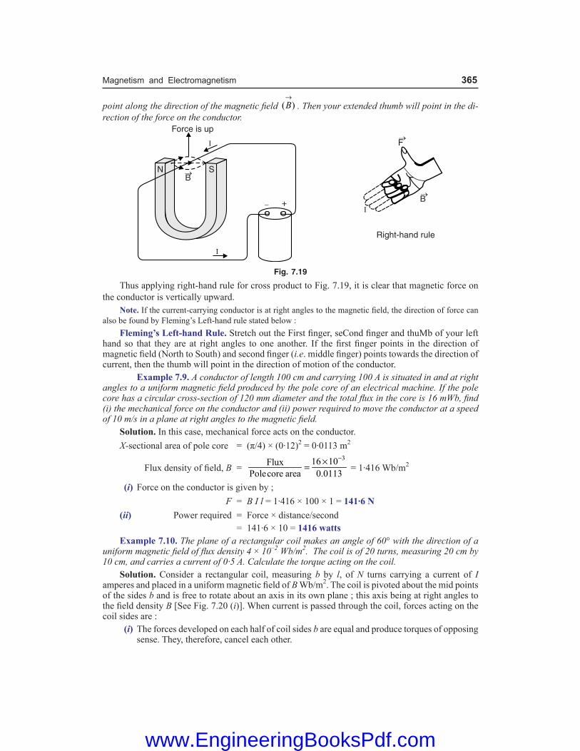
Magnetism and Electromagnetism 365
point along the direction of the magnetic field ( )B→
. Then your extended thumb will point in the di-rection of the force on the conductor.
Fig. 7.19
Thus applying right-hand rule for cross product to Fig. 7.19, it is clear that magnetic force on the conductor is vertically upward. Note. If the current-carrying conductor is at right angles to the magnetic field, the direction of force can also be found by Fleming’s Left-hand rule stated below : Fleming’s Left-hand Rule. Stretch out the First finger, seCond finger and thuMb of your left hand so that they are at right angles to one another. If the first finger points in the direction of magnetic field (North to South) and second finger (i.e. middle finger) points towards the direction of current, then the thumb will point in the direction of motion of the conductor. Example 7.9. A conductor of length 100 cm and carrying 100 A is situated in and at right angles to a uniform magnetic field produced by the pole core of an electrical machine. If the pole core has a circular cross-section of 120 mm diameter and the total flux in the core is 16 mWb, find (i) the mechanical force on the conductor and (ii) power required to move the conductor at a speed of 10 m/s in a plane at right angles to the magnetic field. Solution. In this case, mechanical force acts on the conductor. X-sectional area of pole core = (π/4) × (0·12)2 = 0·0113 m2
Flux density of field, B = 316 10Flux
Polecore area 0.0113
−×= = 1·416 Wb/m2
(i) Force on the conductor is given by ; F = B I l = 1·416 × 100 × 1 = 141·6 N (ii) Power required = Force × distance/second = 141·6 × 10 = 1416 watts Example 7.10. The plane of a rectangular coil makes an angle of 60° with the direction of a uniform magnetic field of flux density 4 × 10⁻² Wb/m2. The coil is of 20 turns, measuring 20 cm by 10 cm, and carries a current of 0·5 A. Calculate the torque acting on the coil. Solution. Consider a rectangular coil, measuring b by l, of N turns carrying a current of I amperes and placed in a uniform magnetic field of B Wb/m2. The coil is pivoted about the mid points of the sides b and is free to rotate about an axis in its own plane ; this axis being at right angles to the field density B [See Fig. 7.20 (i)]. When current is passed through the coil, forces acting on the coil sides are : (i) The forces developed on each half of coil sides b are equal and produce torques of opposing
sense. They, therefore, cancel each other.
www.EngineeringBooksPdf.com

366 Basic Electrical Engineering
(ii) The coil sides l always remain at right angles to the field as the coil rotates. The force F acting on each of the coil sides l gives rise to a torque as shown in Fig. 7.20 (ii).
Force on each coil side l, F = B I l N newtons
Fig. 7.20
The perpendicular distance between the lines of action of the two forces is b cos θ. \ Torque, T = F × b cos θ = (B I l N) b cos θ or T = BINA cos θ newton-metrewhere A (= l × b) is the area of the coil. By an extension of this reasoning, the expression may be proved quite generally for a coil of area A and of any shape. In the given problem, the data is
B = 4 × 10⁻² Wb/m2 ; A = 20 × 10 = 200 cm2 = 2 × 10⁻² m2 ; I = 0·5 A ; θ = 60° ; N = 20
\ Torque, T = (4 × 10–2) × (0·5) × (20) × (2 × 10–2) × cos 60° = 4 × 10⁻³ Nm
Tutorial Problems 1. A straight conductor 0·4m long carries a current of 12 A and lies at right angles to a uniform field of
2·5 Wb/m2. Find the mechanical force on the conductor when (i) it lies in the given position (ii) it lies in a position such that it is inclined at an angle of 30º to the direction of field. [(i) 12 N (ii) 6 N]
2. A conductor of length 100 cm and carrying 100 A is situated in and at right angles to a uniform magnetic field of strength 1 Wb/m2. Calculate the force and power required to move the conductor at a speed of 100 m/s in a plane at right angles to the magnetic field. [100 N ; 1000 watts]
3. A d.c. motor consists of an armature winding of 400 turns (equivalent to 800 conductors). The effective lengths of conductor in the field is 160 mm and the conductors are situated at a radius of 100 mm from the centre of the motor shaft. The magnetic flux density is 0·6 Wb/m2 and a current of 25 A flows through the winding. Calculate the torque available at the motor shaft. [192 Nm]
4. A d.c. motor is to provide a torque of 540 Nm. The armature winding consists of 600 turns (equivalent to 1200 conductors). The effective length of a conductor in the field is 250 mm and the conductors are situated at a radius of 150 mm from the centre of the motor shaft. Each conductor carries a current of 10 A. Calculate the flux density which must be provided by the radial field in which the conductors lie.
[1·2 Wb/m2]
7.21. Ampere’s Work Law or Ampere’s Circuital Law The magnetising force (H) at any point in an electromagnetic field is the force experienced by a unit N-pole placed at that point. If the unit N-pole is made to move in a complete path around N current-carrying conductors, then work is done provided the unit N-pole is moved in opposition to
www.EngineeringBooksPdf.com

Magnetism and Electromagnetism 367
the lines of force. Conversely, if the unit N-pole moves in the direction of magnetic field, then work will be done by the magnetic force on whatever force is restraining the movement of the pole. In either case, unit N-pole makes one complete loop around the N conductors. The work done is given by Ampere’s work law stated below : The work done on or by a unit N-pole in moving once around any complete path is equal to the product of current and number of turns enclosed by that path i.e.
*rH dr
→ →⋅∫ = N I
Fig. 7.21where rH
→ is the magnetising force at a distance r. The circle around the integral sign indicates that
the integral is around a complete path. The work law is applicable regardless of the shape of complete path. Thus in Fig. 7.21, paths ‘a’ and ‘b’ completely enclose N conductors. If a unit N-pole is moved once around any of these complete paths, the work done in each case will be equal to N I. Although path ‘c’ is a complete path, it fails to enclose any current carrying conductor. Hence, no work is done in moving a unit N-pole around such a path. Note. The work law is applicable for all magnetic fields, irrespective of the shape of the field or of the materials which may be present.
7.22. Applications of Ampere’s Work Law Ampere’s work law can be used to find magnetising force (H) in simple conductor arrangements. We shall discuss two cases by way of illustration. 1. Magnetising force around a long straight conductor. Consider the case of a long straight conductor carrying a current of I amperes as shown in Fig. 7.22. The conductor will set up magnetic lines of force which encircle it. Consider a circular path of radius r metres. By symmetry, the field intensity H on all the points of this circular path will be the same. If a unit N-pole is moved once around this circular path, then work done is = 2πrH. By work law, this must be equal to the product of current and number of turns enclosed by this circular path. \ 2π r H = I ( N = 1)
or H = 2
Irπ
Fig. 7.22
* This law can also be stated as the closed line integral of magnetic field intensity (H) is equal to the encloed ampere-turns that produce the magnetic field.
www.EngineeringBooksPdf.com

368 Basic Electrical Engineering
Note that magnetic lines of force encircle the conductor like concentric circles. The direction of magnetic lines of force can be determined by right-hand rule. If there had been N turns enclosed by the path, then,
H = 2N I
rπ
Flux density, B = µ0 H = 0
2N I
rµ
π ... in air
= 0
2r N I
rµ µ
π ... in a medium
The following points may be noted carefully : (i) If we choose a complete path for which r is smaller, H on that circle will be large. However,
2π r H will be still equal to N I. (ii) Inspection of above expression reveals that H can
also be expressed in ampere-turns per metre (AT/m). (iii) It is reminded that the quantity N I (i.e. product of
the number of turns in a winding and the current flowing through it) is called magnetomotive force (m.m.f.).
m.m.f. = N I ampere-turns 2. Magnetising force due to long solenoid. Consider a long solenoid of length l and wound uniformly with N turns (See Fig. 7.23). The length of the solenoid is much greater than the breadth, say 10 times greater. The following assumptions are permissible : (i) The field strength external to the solenoid is effectively zero. (ii) The field strength inside the solenoid is uniform. Suppose the current I flowing through the solenoid produces uniform magnetic field strength H within the solenoid. Applying work law to any closed path say dotted one shown in Fig. 7.23, Total work done around closed path = Ampere turns linked Since there is negligible field strength (H) outside the solenoid, the only work done will be in travelling length l within the solenoid. \ H × l = NI
or H = NIl AT/m or A/m
Incidentally, B = µ0 H = 0 NIl
µ Wb/m2 ...in air
= µ0 µr H = 0 r NIl
µ µ Wb/m2 ...in a medium
It is reminded that the magnetic field strength (H) is a vector quantity since it has magni-tude and direction. Example 7.11. An air-cored toroidal coil shown in Fig. 7.24 has 3000 turns and carries a cur-rent of 0.1A. The cross-sectional area of the coil is 4 cm2 and the length of the magnetic circuit is 15 cm. Determine the magnetic field strength, the flux density and the total flux within the coil.
Solution. N = 3000 turns ; I = 0.1 A ; A = 4 × 10⁻⁴ m2 ; l = 15 × 10–2 m
Magnetic field strength, H = 2
3000 0.1
15 10
NIl −
×=×
= 2000 AT/m
Fig. 7.23
www.EngineeringBooksPdf.com

Magnetism and Electromagnetism 369
Flux density, B = µ0H = 4p × 10–7 × 2000 = 2.5 × 10⁻³ Wb/m2
Total flux, f = B × A = 2.5 × 10–3 × 4 × 10–4
= 1 × 10⁻⁶ Wb = 1 µWb Example 7.12. An air-cored solenoid has length of 15 cm and inside diameter of 1.5 cm. If the coil has 900 turns, determine the total flux within the solenoid when the coil current is 100 mA. Solution. For a solenoid, the length of the magnetic circuit, l = coil length = 15 × 10–2 m. D = 1.5 × 10⁻² m ; N = 900 turns ; I = 100 × 10–3 A \ m.m.f. = NI = 900 × 100 × 10–3 = 90 AT
Magnetising force, H = m.m.f.l
= 290
15 10−× = 600 AT/m
Magnetic flux density, B = µ0H = 4p × 10–7 × 600 = 24p × 10–5 Wb/m2
\ Total flux, f = BA = 24p × 10–5 × 2
4Dπ
= 24p × 10–5 × p × 2 2(1.5 10 )
4
−× = 1.33 × 10⁻⁷ Wb
If the solenoid were iron-cored, the magnitude of the magnetic flux within the solenoid would have been much greater than the calculated value because of very high relative permeability of iron.
7.23. Biot-Savart Law A conductor carrying current I produces a magnetic field around it. We can consider the current carrying conductor to be consisting of infinitesimally small *current elements I dl
→; each
current element contributing to magnetic field. Biot-Savart law gives us expression for the magnetic field at a point due to a current element. Consider a current element I dl
→ of a conductor XY carrying
current I [See Fig. 7.25]. Let P be the point where the magnetic
field dB→
due to the current element is to be found. Suppose r→
is the position vector of point P from the current element I dl→
and q is the angle between dl
→ and .r
→
According to Biot-Savart law, the magnitude dB of magnetic field at point P due to the current element depends upon the following factors :
(i) dB ∝ I (ii) dB ∝ dl (iii) dB ∝ 1/r2 (iv) dB ∝ sinq
Combining all these four factors, we get,
dB ∝ 2
sinI dlr
θ
or dB = 2
sinI dlKr
θ
Fig. 7.24
Fig. 7.25
* The current element I dl→
is a vector. Its direction is tangent to the element and acts in the direction of flow of current in the conductor.
www.EngineeringBooksPdf.com

370 Basic Electrical Engineering
where K is a constant of proportionality. Its value depends on the medium in which the conductor is situated and the system of units adopted.
For free space and SI units, K = 0
4µ
π = 10–7 Tm A–1
where µ0 = Absolute permeability of free space = 4p × 10–7 Tm A–1
\ dB = 02
sin4
Idlr
µ θ⋅π ...(i)
Eq. (i) is known as Biot-Savart law and gives the magnitude of the magnetic field at a point due
to small current element I dl→
. Note that Biot-Savart law holds strictly for steady currents.
In vector form. dB→
= 03
( )4
I dl rr
→ →µ ×
π ...(ii)
The Biot-Savart law is analogous to Coulomb’s law. Just as the charge q is the source of
electrostatic field, similarly, the source of magnetic field is the current element I dl→
.
Direction of B→
. dB→
= 03
( )4
I dl rr
→ →µ ×
π
The direction of dB→
is perpendicular to the plane containing dl→
and r→
. By right-hand rule for the cross product, the field is directed inward. Magnetic field due to whole conductor. Eq. (ii) gives the magnetic field at point P due to a
small current element I dl→
. The total magnetic field at point P is found by summing (integrating) over all current elements.
B→
= dB→
∫ = 03
( )4
I dl rr
→ →µ ×
π∫where the integration is taken over the entire conductor in which current I flows.
Special cases. dB = 02
sin4
I dlr
µ θ⋅π
(i) When q = 0° i.e., point P lies on the axis of the conductor, then,
dB = 02
sin 04
I dlr
µ °⋅π = 0
Hence, there is no magnetic field at any point on the thin linear current carrying conductor.
(ii) When q = 90° i.e., point P lies at a perpendicular position w.r.t. current element, then,
dB = 0 02 2
sin904 4
I dl I dlr r
µ µ°⋅ = ⋅π π ... Maximum value
Hence magnetic field due to a current element is maximum in a plane passing through the element and perpendicular to its axis. (iii) When q = 0° or 180°, dB = 0 ...Minimum value
Important points about Biot-Savart law. This law has the following salient features : (i) Biot-Savart law is valid for symmetrical current distributions. (ii) Biot-Savart law cannot be proved experimentally because it is not possible to have a current
carrying conductor of length dl. (iii) Like Coulomb’s law in electrostatics, Biot-Savart law also obeys inverse square law.
(iv) The direction of dB→
is perpendicular to the plane containing I dl→
and r→
.
www.EngineeringBooksPdf.com

Magnetism and Electromagnetism 371
7.24. Applications of Biot-Savart Law Biot-Savart law is very useful in determining magnetic flux density B and hence magnetising force H (= B/µ0) due to current-carrying conductor arrangements. We shall discuss the following cases by way of illustration. (i) Magnetic flux density at the centre of current-carrying circular coil. (ii) Magnetic flux density due to straight conductor carrying current.
(iii) Magnetic flux density on the axis of circular coil carrying current.
7.25. Magnetic Field at the Centre of Current-Carrying Circular Coil This is a practical case because the operation of many devices depends upon the magnetic field produced by the current-carrying circular coil. Consider a circular coil of radius r and carrying current I in the direction shown in Fig. 7.26. Suppose the loop lies in the plane of paper. It is desired to find the magnetic field at the centre O of the coil. Suppose the entire circular coil is divided into a large number of current elements, each of length dl. According
to Biot-Savart law, the magnetic field dB→
at the centre O of the
coil due to current element I dl→
is given by ;
dB→
= 03
µ ( )4
I dl rr
→ →×
π
where r→
is the position vector of point O from the current element.
The magnitude of dB→
at the centre O is
dB = 0 03 2
µ µsin sin4 4
I dl r I dlr r
θ θ=π π ...(i)
The direction of dB→
is perpendicular to the plane of the coil and is directed inwards. Since each current element contributes to the magnetic field in the same direction, the total magnetic field B at the centre O can be found by integrating eq. (i) around the loop i.e.
B = 02
µ sin4
I dldBr
θ=π∫ ∫
For each current element, angle between dl→
and r→
is 90°. Also distance of each current element from the centre O is r.
\ B = 02
µ sin 904
I dlr
°π ∫
Now, dl∫ = Total length of the coil = 2π r
\ B = 02
µ(2 )
4I r
rπ
π
or B = 0µ2
Ir
Also, H = 0
0 0
12 2
IB Ir r
µ= × =µ µ
If the coil has N turns, each carrying current in the same direction, then contributions of all the turns are added up. Therefore, the magnetic field at the centre of the coil is greatly increased and is given by ;
Fig. 7.26
www.EngineeringBooksPdf.com

372 Basic Electrical Engineering
B = 0µ2N Ir
Also, H = 0µ 2
B NIr
=
Direction of B→
. The direction of magnetic field B→
is perpendicular to the plane of the coil and for Fig. 7.27, magnetic field inside the coil is directed inwards. The magnetic lines of force are circular near the wire but practically straight near the centre of the coil. In the middle M of the coil, the magnetic field is uniform for a short distance on either side. The direction of magnetic field at the centre of a current-carrying circular coil can be determined by right-hand palm rule.
Fig. 7.27
Right-hand palm rule. Orient the thumb of your right hand perpendicular to the grip of the fingers such that curvature of the fingers points in the direction of current in the circular coil. Then thumb will point in the direction of the magnetic field near the centre of the circular coil.
7.26. Magnetic Field Due to Straight Conductor Carrying Current Consider a straight conductor XY carrying current I in the direction shown in Fig. 7.28. It is desired to find the magnetic field at point P located at a perpendicular distance a from the conductor
(i.e. PQ = a). Consider a small current element of length dl. Let r→
be the position vector of point P
from the current element and θ be the angle between dl→
and r→
(i.e., ∠POQ = θ). Let us further assume that QO = l. According to Biot-Savart law, the magnitude of
magnetic field dB→
at point P due to the considered current element is given by ;
dB = 02
µ sin4
I dlr
θπ ...(i)
To get the total magnetic field B, we must integrate eq. (i) over the whole conductor. As we move along the conductor, the quantities dl, θ and r change. The integration becomes much easier if we express everything in terms of angle f shown in Fig. 7.28. In the right angled triangle PQO, θ = 90° – f. \ sin θ = sin (90° – f) = cos f
Fig. 7.28
www.EngineeringBooksPdf.com

Magnetism and Electromagnetism 373
Also, cos f = ar or r =
cosa
φ
Further, tan f = la or l = a tan f
or dl = a sec2f df Putting the values of sin θ, dl and r in eq. (i), we have,
dB = 2
02
µ ( sec ) cos4 ( / cos )
I a da
φ φ φπ φ
or dB = 0µ cos4
I daφ φ
π ...(ii)
The direction of dB→
is perpendicular to the plane of the conductor and is directed inwards (Right-hand grip rule, See section 7.17). Since each current element contributes to the magnetic field in the same direction, the total magnetic field B at point P can be found by integrating eq. (ii) over the length XY i.e.
B = 2 2
1 1
0µcos
4
IdB da
φ φ
−φ −φ= φ φ
π∫ ∫ = 2
1
0 02 1
µ µ[sin ] (sin sin )
4 4
I Ia a
φ−φφ = φ + φ
π π
\ B = 02 1
µ(sin sin )
4Ia
φ + φπ ...(iii)
Also, H = 2 10
(sin sin )µ 4B I
a= φ + φ
π Eq. (iii) gives the value of B at point P due to a conductor of finite length.Special cases. We shall discuss a few important cases. (i) When the conductor XY is of infinite length and point P lies at the centre of the conductor. In this case, f1 = f2 = 90° = π/2.
\ B = 0µ(sin /2 sin /2)
4Ia
π + ππ
or B = 0µ 24
Iaπ
Also, H = 0
1 24 2
B I Ia a
= ⋅ =µ π π
(ii) When conductor XY is of infinite length but point P lies near one end Y (or X). In this case, f1 = 90° and f2 = 0°.
\ B = 0µ(sin 90 sin 0 )
4Ia
° + °π
or B = 0µ4
Iaπ
Note that it is half of that for case (i).
Also, H = 0 4
B Ia
=µ π
(iii) If the length of the conductor is finite (say l) and point P lies on the right bisector of the conductor. In this case, f1 = f2 = f.
www.EngineeringBooksPdf.com

374 Basic Electrical Engineering
Now, sin f = 2 2 2 2
/2
( / 2) 4
l la l a l
=+ +
\ B = 0 0µ µ 2(sin sin ) sin4 4
I Ia a
φ + φ = φπ π
or B = 0
2 2
µ 24 4
I la a lπ +
Also H = 2 20
1 24 4
B I la a l
= ⋅µ π +
Direction of B→
. For a long straight conductor carrying current, the magnetic lines of force are concentric circles with conductor as the centre ; the direction of magnetic lines of force can be found
by right-hand grip rule. The direction of B→
at any point is along the tangent to field line at that point as shown in Fig. 7.29.
Fig. 7.29
Note. For a given current, B ∝ 1/a so that graph between B and a is a hyperbola.
7.27. Magnetic Field on the Axis of Circular Coil Carrying Current Consider a circular coil of radius a, centre O and carrying a current I in the direction shown in Fig. 7.30. Let the plane of the coil be perpendicular to the plane of the paper. It is desired to find the magnetic field at a point P on the axis of the coil such that OP = x.
Fig. 7.30
Consider two small current elements, each of length dl, located diametrically opposite to each other at Q and R. Suppose the distance of Q or R from P is r i.e. PQ = PR = r.
www.EngineeringBooksPdf.com

Magnetism and Electromagnetism 375
\ r = 2 2a x+ According to Biot-Savart law, the magnitude of magnetic field at P due to current element at Q is given by ; dB = 0
2
µ sin 904
I dlr
°π ( θ* = 90°)
or dB = 02 2
µ4 ( )
I dla xπ +
...(i)
The magnetic field at P due to current element at Q is in the plane of paper and at right angles to r
→and in the direction shown.
Similarly, magnitude of magnetic field at point P due to current element at R is given by ;
dB′ = 02 2
µ4 ( )
I dla xπ +
...(ii)
It also acts in the plane of paper and at right angles to r→
but in opposite direction to dB. From eqs. (i) and (ii), dB = dB′. It is clear that vertical components (dB cos α and dB′ cos α) will be equal and opposite and thus cancel each other. However, components along the axis of the coil (dB sin α and dB′ sin α) are added and act in the direction PX. This is true for all the diametrically opposite elements of the circular coil. Therefore, when we sum up the contributions of all the current elements of the coil, the perpendicular components will cancel. Hence the resultant magnetic field at point P is the vector sum of all the components dB sin α over the entire coil.
\ B = 0 02 2 2 2
µ sin µ sinsin
4 ( ) 4 ( )
I dl IdB dla x a x
α αα = =π + π +∫ ∫ ∫
Now sin α = 2 2
aa x+
and 2dl a= π∫
\ B = 2
02 2 3/2
µ
2( )
I aa x+
along PX ...(iii)
Also, H = 2
2 2 3 20 2( )
B Iaa x
=µ +
If the circular coil has N turns, then,
B = 2
02 2 3/2
µ
2( )
NI aa x+
along PX ...(iv)
Also, H = 2
2 2 3 20 2( )
B NIaa x
=µ +
Different Cases. Let us discuss some special cases. (i) When point P is at the centre of the coil. In this case, x = 0 and eq. (iv) becomes :
B = 2
0 03
µ
22
NIa NIaa
µ=
This is the expression for the magnetic field at the centre of a current-carrying circular coil already derived in section 7.25. Note that the value of magnetic field is maximum at the centre of the coil.
* The radius vector QP of each current element is perpendicular to it so that q = 90° in each case.
www.EngineeringBooksPdf.com

376 Basic Electrical Engineering
Also, H = 0 2
B NIa
=µ
(ii) When point P is far away from the centre of coil. In this case, x >> a so that a2 + x2 x2.
\ B = 2
03
µ
2
NI ax
Also, H = 2
30 2
B NIax
=µ
The magnetic field is directed along the axis of the coil and falls off as the cube of the distance from the coil. Direction of B
→. The magnetic field at the centre of a coil carrying current is along the axis of
the coil as shown in Fig. 7.31. The direction of magnetic field can be determined by using right-hand fist rule. Hold the axis of the coil in the right-hand fist in such a way that fingers point in the direction of current in the coil. Then outstretched thumb gives the direction of the magnetic field. Applying this rule to Fig. 7.31, it is clear that direction of magnetic lines of force is along the axis of the coil as shown.
Fig. 7.31 Example 7.13. How far from a compass should a wire carrying 1 A current be located if its magnetic field at the compass is not to exceed 1 percent of the *earth’s magnetic field (3 × 10⁻⁵ Wb/m2) ? Solution. Let r metre be the desired distance. Required flux density at the compass is B = 1% of Earth’s flux density = 0·01 × 3 × 10–5 = 3 × 10⁻⁷ Wb/m2
Required magnetising force at the compass is
H = 7
70
3 10
4 10
B −
−×=
µ π× = 0·239 AT/m
Now, H = 2
Irπ \ r = 1
2 2 0 239IH
=π π × ⋅ = 0·67 m
Example 7.14. A horizontal overhead power line carries a current of 50 A in west to east direction. What is the magnitude and direction of the magnetic field 1·5 m below the line ?* Earth’s magnetic field. The earth itself has a weak magnetic field. This is believed to be caused by electric
currents circulating within its core. The currents are probably generated by convection in the liquid core maintained by radioactive heating of the earth’s interior.
www.EngineeringBooksPdf.com
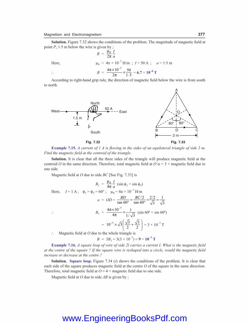
Magnetism and Electromagnetism 377
Solution. Figure 7.32 shows the conditions of the problem. The magnitude of magnetic field at point P, 1·5 m below the wire is given by ;
B = 0
2Ia
µπ
Here, µ0 = 4p × 10–7 H/m ; I = 50 A ; a = 1·5 m
\ B = 74 10 50
2 1 5
−π× ×π ⋅ = 6.7 × 10⁻⁶ T
According to right-hand grip rule, the direction of magnetic field below the wire is from south to north.
Fig. 7.32 Fig. 7.33
Example 7.15. A current of 1 A is flowing in the sides of an equilateral triangle of side 2 m. Find the magnetic field at the centroid of the triangle. Solution. It is clear that all the three sides of the triangle will produce magnetic field at the centroid O in the same direction. Therefore, total magnetic field at O is = 3 × magnetic field due to one side. Magnetic field at O due to side BC [See Fig. 7.33] is
B1 = 0
4Ia
µπ (sin f1 + sin f2)
Here, I = 1 A ; f1 = f2 = 60° ; µ0 = 4π × 10–7 H/m
a = OD = /2 2/2 1tan 60 tan 60 3 3
BD BC= = =° °
\ B1 = 74 10 1
4 1/ 3
−π× ×π (sin 60º + sin 60º)
= 7 3 310 32 2
− × +
= 3 × 10⁻⁷ T
\ Magnetic field at O due to the whole triangle is B = 3B1 = 3(3 × 10⁻⁷) = 9 × 10⁻⁷ T Example 7.16. A square loop of wire of side 2l carries a current I. What is the magnetic field at the centre of the square ? If the square wire is reshaped into a circle, would the magnetic field increase or decrease at the centre ? Solution. Square loop. Figure 7.34 (i) shows the conditions of the problem. It is clear that each side of the square produces magnetic field at the centre O of the square in the same direction. Therefore, total magnetic field at O = 4 × magnetic field due to one side. Magnetic field at O due to side AB is given by ;
www.EngineeringBooksPdf.com

378 Basic Electrical Engineering
B1 = 0
4Ia
µπ (sin f1 + sin f2)
Here µ0 = 4π × 10–7 H/m ; f1 = f2 = 45º ; a = OM = AB/2 = l
\ B1 = 74 10
4Il
−π× ×π (sin 45° + sin 45°)
= 7 7210 2 10 T2
I Il l
− − × = × Magnetic field at O due to the whole square is
B = 4B1 = –74 2 × 10I Tl ...(i)
Circular loop. The total length of the square loop = 4 × 2l = 8l. When this square loop is shaped into a circular loop of radius r, then [See Fig. 7.34 (ii)],
2π r = 8l or r = 8 42
l l=π π
Fig. 7.34
Magnetic field at the centre of the circular loop is
B = 7 2
70 4 1010
2 2(4 / ) 2I I I
r l l
−−µ π× × π= = × ×
π
\ B = –74.93 × × 10I Tl
...(ii)
Comments. Inspection of eqs. (i) and (ii) reveals that magnetic field in case of square loop will be more. Example 7.17. A current of 15A is passing along a straight wire. Calculate the force on a unit N-pole placed 0.15 metre from the wire. If the wire is bent to form into a loop, calculate the diameter of the loop so as to produce the same force at the centre of the coil upon a unit N-pole when carrying a current of 15A. Solution. By definition, the force on the unit N-pole is the magnetising force H. Therefore, force on a unit N-pole placed at a point 0.15 m (i.e. a = 0.15m) from a long straight wire carrying current I(= 15A) is given by ; H = 15
2 2 0.15Ia
=π π × =
50 AT m or N Wbπ
Force on a unit N-pole placed at the centre of a loop of radius r when the loop carries a current I(= 15 A) is
www.EngineeringBooksPdf.com

Magnetism and Electromagnetism 379
H ′ = 152 2Ir r
= AT/m
As per the statement of the problem, H′ = H.
\ 152r = 50
π or r = 152 50
π× = 0.4713 m
\ Diameter of loop, D = 2r = 2 × 0.4713 = 0.9426 m = 94.26 cm
Tutorial Problems 1. A horizontal overhead power line carries a current of 90 A in east to west direction. What is the magnitude
and direction of magnetic field due to the current 1·5 m below the wire ? [1·2 × 10–5 T towards south] 2. A long straight wire is turned into a loop of radius 10 cm as shown in Fig. 7.35. If a current of 8 A is
passed, then find the value of magnetic field at the centre O of the loop. [3·4 × 10–5 T perpendicular to plane of paper pointing upward]
[Hint : The magnetic field at O due to straight wire is perpendicular to the plane of paper and is directed downward. However, field due to circular loop is directed in opposite direction.]
Fig. 7.35 Fig. 7.36
3. A circular segment of radius 10 cm subtends an angle of 60° at its centre. A current of 9 A is flowing through it. Find the magnitude and direction of magnetic field produced at the centre [See Fig. 7.36].
[9·42 × 10–6 T perpendicular to the plane of paper pointing downward] [Hint : The magnetic field at the centre of a single turn circular coil is
B = 0
2I
aµ ... a is the radius of coil.
For the given arc, B = 060360 2
Ia
µ ° °
4. A long wire having a semicircular loop of radius a carries a current I amperes as shown in Fig. 7.37. Find
the magnetic field at the centre of the semicircular arc.
0µ4
Ia
[Hint : The straight portions AB and DE do not contribute to any magnetic field at O. Therefore, magnetic field at O is only due to semicircular loop.]
Fig. 7.37 Fig. 7.38
www.EngineeringBooksPdf.com

380 Basic Electrical Engineering
5. The wire shown in Fig. 7.38 carries a current I. What will be the magnitude and direction of magnetic field at the centre O ? Assume that various portions of wire do not touch each other at P.
( )
0µ 11 +2
Iperpendicular to the plane of paper directed upward
a π [Hint : The magnetic field due to straight conductor and that due to circular part aid each other at O.]
7.28. Force Between Current-Carrying Parallel Conductors When two current-carrying conductors are parallel to each other, a mechanical force acts on each of the conductors. This force is the result of each conductor being acted upon by the magnetic field produced by the other. If the currents are in the same direction, the forces are attractive ; if currents are in opposite direction, the forces are repulsive. This can be beautifully illustrated by drawing the magnetic field produced by each conductor. (i) Currents in the same direction. Consider two parallel conductors A and B carrying cur-rents in the same direction (i.e. into the plane of paper) as shown in Fig. 7.39 (i). Each conductor will set up its own magnetic field as shown. It is clear that in the space between A and B, the two fields are in opposition and hence they tend to cancel each other. However, in the space outside A and B, the two fields assist each other. Hence the resultant field distribution will be as shown in Fig. 7.39 (ii).
Fig. 7.39
Since magnetic lines of force behave as stretched elastic cords, the two conductors are attracted towards each other. Alternatively, the conductors can be viewed as moving away from the relatively strong field (in the space outside A and B) into the weaker field between the conductors. (ii) Currents in opposite direction. Consider two parallel conductors A and B carrying currents in the opposite direction as shown in Fig. 7.40. Each conductor will set up its own field as shown. It is clear that in the space outside A and B, the two fields are in opposition and hence they tend to cancel each other. However, in the space between A and B, the two fields assist each other. The lateral pressure between lines of force exerts a force on the conductors tending to push them apart. In other words, the conductors experience a repulsive force. If currents are in the same directions, the conductors attract each other ; if currents are in op-posite directions, the conductors repel each other.
7.29. Magnitude of Mutual Force Fig. 7.41 (i) shows two parallel conductors placed in air and carrying currents in the same direction. Here I1 and I2 are the currents in conductors 1 and 2 respectively, l is the length of each conductor in metres and d is the distance between conductors in metres. It is clear that each of the two parallel conductors lies in the magnetic field of the other conductor.
Fig. 7.40
www.EngineeringBooksPdf.com

Magnetism and Electromagnetism 381
Fig. 7.41
In order to determine the magnitude of force, we can consider conductor 2 placed in the magnetic field produced by conductor 1 as shown in Fig. 7.41 (ii). Now field intensity H due to current I1 in conductor 1 at the centre of conductor 2 is given by ;
H = 1
2I
dπ
But B = µ0 µr H = µ0 H = 0 1
2Id
µπ [For air, µr = 1]
Force acting on conductor 2 is given by ;
F = B I2 l = 0 122
I I ld
µ π
= 7
1 24 102
I I ld
−π ×π = 71 22
10I I l
d−× newtons
\ F = 71 2210 N
I I ld
−×
It can be easily shown that conductor 1 will experience an equal force in the opposite direction [See Fig. 7.41 (ii)]. Force per metre run of the conductor is given by ;
F ′ = 71 2210 N m
I Id
−×
According to Fleming’s left-hand rule, the two conductors will attract each other.
7.30. Definition of Ampere The force acting between two parallel conductors has led to the modern definition of an ampere. We have seen above that force between two parallel current-carrying conductors is
F = 71 2210
I I ld
−× newtons
If I1 = I2 = 1A ; l = 1 m ; d = 1 m, then,
F = 7 72 1 1 110 2 10 N
1− −× × × × = ×
Hence one ampere is that current which, if maintained in two long parallel conductors, and placed 1 m apart in vacuum, would produce between these conductors a force equal to 2 × 10⁻⁷ newton per metre of length (See Fig. 7.42). Historically, the ampere was fixed originally in a very different way. The constant 2 × 10⁻⁷ that appears in the modern definition was chosen so as to keep the magnitude of ampere the same as formerly.
Fig. 7.42
www.EngineeringBooksPdf.com
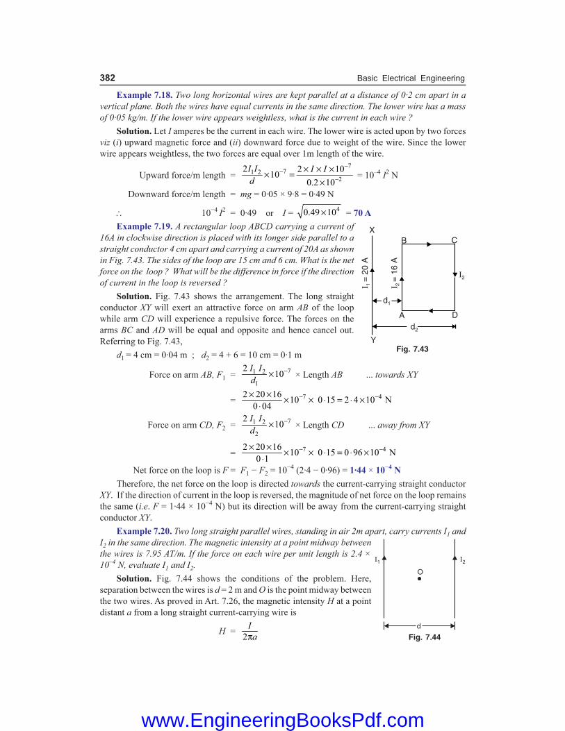
382 Basic Electrical Engineering
Example 7.18. Two long horizontal wires are kept parallel at a distance of 0·2 cm apart in a vertical plane. Both the wires have equal currents in the same direction. The lower wire has a mass of 0·05 kg/m. If the lower wire appears weightless, what is the current in each wire ? Solution. Let I amperes be the current in each wire. The lower wire is acted upon by two forces viz (i) upward magnetic force and (ii) downward force due to weight of the wire. Since the lower wire appears weightless, the two forces are equal over 1m length of the wire.
Upward force/m length = 7
71 22
2 2 1010
0.2 10
I I I Id
−−
−× × ×× =
× = 10–4 I2 N
Downward force/m length = mg = 0·05 × 9·8 = 0·49 N
\ 10−4 I2 = 0·49 or I = 40.49 10× = 70 A Example 7.19. A rectangular loop ABCD carrying a current of 16A in clockwise direction is placed with its longer side parallel to a straight conductor 4 cm apart and carrying a current of 20A as shown in Fig. 7.43. The sides of the loop are 15 cm and 6 cm. What is the net force on the loop ? What will be the difference in force if the direction of current in the loop is reversed ? Solution. Fig. 7.43 shows the arrangement. The long straight conductor XY will exert an attractive force on arm AB of the loop while arm CD will experience a repulsive force. The forces on the arms BC and AD will be equal and opposite and hence cancel out. Referring to Fig. 7.43, d1 = 4 cm = 0·04 m ; d2 = 4 + 6 = 10 cm = 0·1 m
Force on arm AB, F1 = 71 2
1
210
I Id
−× × Length AB ... towards XY
= 7 42 20 1610 0 15 2 4 10 N
0 04− −× × × × ⋅ = ⋅ ×
⋅
Force on arm CD, F2 = 71 2
2
210
I Id
−× × Length CD ... away from XY
= 7 42 20 1610 0 15 0 96 10 N
0 1− −× × × × ⋅ = ⋅ ×
⋅ Net force on the loop is F = F1 − F2 = 10−4 (2·4 − 0·96) = 1·44 × 10−4 N Therefore, the net force on the loop is directed towards the current-carrying straight conductor XY. If the direction of current in the loop is reversed, the magnitude of net force on the loop remains the same (i.e. F = 1·44 × 10−4 N) but its direction will be away from the current-carrying straight conductor XY. Example 7.20. Two long straight parallel wires, standing in air 2m apart, carry currents I1 and I2 in the same direction. The magnetic intensity at a point midway between the wires is 7.95 AT/m. If the force on each wire per unit length is 2.4 × 10⁻⁴ N, evaluate I1 and I2. Solution. Fig. 7.44 shows the conditions of the problem. Here, separation between the wires is d = 2 m and O is the point midway between the two wires. As proved in Art. 7.26, the magnetic intensity H at a point distant a from a long straight current-carrying wire is
H = 2
Iaπ
Fig. 7.43
Fig. 7.44
www.EngineeringBooksPdf.com

Magnetism and Electromagnetism 383
Since the two wires are carrying currents in the same direction, the net magnetic intensity H at O is the difference of the magnetic intensities at O due to two currents i.e. H = H1 – H2
or 7.95 = 1 2
2 1 2 1I I−
π × π × ( point O is 1m from each wire)
\ I1 – I2 = 50 ...(i) As proved in Art. 7.29, force per unit length of the conductors is
F = 71 2210
I Id
−×
or 2.4 × 10–4 = 71 2210
2I I −×
\ I1I2 = 2400
Now, (I1 + I2)2 = (I1 – I2)
2 + 4I1I2 = (50)2 + 4 × 2400 = 12100 \ I1 + I2 = 110 ...(ii) From eqs. (i) and (ii), I1 = 80A ; I2 = 30A Example 7.21. A horizontal straight wire 5 cm long of mass 1·2 g/m is placed perpendicular to a uniform magnetic field of 0·6 T. If resistance of the wire is 3·8 Ω m–1, calculate the p.d. that has to be applied between the ends of the wire to make it just self-supporting. Solution. The current (I) in the wire is to be in such a direction that magnetic force acts on it vertically upward. To make the wire self-supporting, its weight should be equal to the upward magnetic force i.e. B I l = m g ( θ = 90°)
or I = mgBl
Here, m = 1·2 × 10–3 l ; B = 0·6 T ; g = 9·8 ms–2
\ I = 3(1 2 10 ) 9 8
0 6ll
−⋅ × × ⋅⋅ × = 19·6 × 10–3 A
Resistance of the wire, R = 0·05 × 3·8 = 0·19 Ω
\ Required P.D., V = I R = (19·6 × 10–3) 0·19 = 3·7 × 10–3 V
Tutorial Problems 1. A pair of rising mains has a spacing of 200 mm between centres. If each conductor carries 500 A, determine
the force between the conductors for each 10m length of run. [2·5 N repulsive] 2. Two busbars, each 20 m long, feed a circuit and are spaced at a distance of 80 mm inbetween centres. If
a short-circuit current of 20,000 A flows through the conductors, calculate the force per metre between the bars. [1000 N]
3. Two long straight parallel conductors carry the same current I in the same direction. The conductors are placed 20 cm apart in air. The magnetic flux density between the conductors 5 cm from one of them is 1·33 × 10−5 Wb/m2. If the force on each conductor per metre length is 25 × 10−6 N, find the current in each conductor. [5 A]
4. The wires that supply current to a 120 V, 2kW electric heater are 2 mm apart. What is the force per metre between the wires ? [0·028 N/m]
5. The busbars 10 cm apart are supported by insulators every metre along their length. The busbars each carry a current of 15 kA. What is the force acting on each insulator ? [450 N]
www.EngineeringBooksPdf.com

384 Basic Electrical Engineering
Objective Questions
1. When a magnet is heated, (i) it gains magnetism (ii) it loses magnetism (iii) it neither loses nor gains magnetism (iv) none of the above 2. The magnetic material used in permanent
magnets is (i) iron (ii) soft steel (iii) nickel (iv) hardened steel 3. The magnetic material used in temporary
magnets is (i) hardened steel (ii) cobalt steel (iii) soft iron (iv) tungsten steel 4. Magnetic flux density is a (i) vector quantity (ii) scalar quantity (iii) phasor (iv) none of the above 5. The relative permeability of a ferromagnetic
material is 1000. Its absolute permeability will be
(i) 106 H/m (ii) 4π × 10−3 H/m (iii) 4π × 10−11 H/m (iv) none of the above 6. The main advantage of temporary magnets is
that we can (i) change the magnetic flux (ii) use any magnetic material (iii) decrease the hysteresis loss (iv) none of the above 7. One weber is equal to (i) 106 lines (ii) 4π × 10−7 lines (iii) 1012 lines (iv) 108 lines 8. Magnetic field intensity is a (i) scalar quantity (ii) vector quantity (iii) phasor (iv) none of the above 9. The absolute permeability of a material having
a flux density of 1 Wb/m2 is 10−3 H/m. The value of magnetising force is
(i) 10−3 AT/m (ii) 4π × 10−3 AT/m (iii) 1000 AT/m (iv) 4π × 103 AT/m 10. When the relative permeability of a material is
slightly less than 1, it is called a (i) diamagnetic material (ii) paramagnetic material (iii) ferromagnetic material (iv) none of the above 11. The greater percentage of substances are
(i) diamagnetic (ii) paramagnetic (iii) ferromagnetic (iv) none of the above 12. When the relative permeability of material is
much greater than 1, it is called (i) diamagnetic material (ii) paramagnetic material (iii) ferromagnetic material (iv) none of the above 13. The magnetic flux density in an air-cored coil
is 10−2 Wb/m2. With a cast iron core of relative permeability 100 inserted, the flux density will become
(i) 10−4 Wb/m2 (ii) 104 Wb/m2
(iii) 10−2 Wb/m2 (iv) 1 Wb/m2
14. Which of the following is more suitable for the core of an electromagnet ?
(i) soft iron (ii) air (iii) steel (iv) tungsten steel 15. The source of a magnetic field is (i) an isolated magnetic pole (ii) static electric charge (iii) magnetic substances (iv) current loop 16. A magnetic needle is kept in a uniform magnetic
field. It experiences (i) a force and a torque (ii) a force but not a torque (iii) a torque but not a force (iv) neither a torque nor a force 17. The unit of pole strength is (i) A/m2 (ii) Am (iii) Am2 (iv) Wb/m2
18. When the relative permeability of a material is slightly more than 1, it is called a
(i) diamagnetic material (ii) paramagnetic material (iii) ferromagnetic material (iv) none of the above
19. AT/m is the unit of (i) m.m.f. (ii) reluctance (iii) magnetising force (iv) magnetic flux density 20. A magnetic needle is kept in a non-uniform
magnetic field. It experiences
www.EngineeringBooksPdf.com

Magnetism and Electromagnetism 385
(i) a force and a torque (ii) a force but not a torque (iii) a torque but not a force (iv) neither a force nor a torque 21. Magnetic flux passes more readily through (i) air (ii) wood (iii) vacuum (iv) iron 22. Iron is ferromagnetic (i) above 770oC (ii) below 770oC (iii) at all temperatures (iv) none of the above
23. The relative permeability of a material is 0·9998. It is
(i) diamagnetic (ii) paramagnetic (iii) ferromagnetic (iv) none of the above 24. Magnetic lines of force (i) intersect at infinity (ii) intersect within the magnet (iii) cannot intersect at all (iv) none of the above 25. Demagnetising of magnets can be done by (i) rough handling (ii) heating (iii) magnetising in opposite direction (iv) all of the above
Answers 1. (ii) 2. (iv) 3. (iii) 4. (i) 5. (ii) 6. (i) 7. (iv) 8. (ii) 9. (iii) 10. (i) 11. (ii) 12. (iii) 13. (iv) 14. (i) 15. (iv) 16. (iii) 17. (ii) 18. (ii) 19. (iii) 20. (i) 21. (iv) 22. (ii) 23. (i) 24. (iii) 25. (iv)
www.EngineeringBooksPdf.com

Introduction We have seen that magnetic lines of force form closed loops around and through the magnetic material. The closed path followed by magnetic flux is called a magnetic circuit just as the closed path followed by current is called an electric circuit. Many electrical devices (e.g. generator, motor, transformer etc.) depend upon magnetism for their operation. Therefore, such devices have magnetic circuits i.e. closed flux paths. In order that these devices function efficiently, their magnetic circuits must be properly designed to obtain the required magnetic conditions. In this chapter, we shall focus our attention on the basic principles of magnetic circuits and methods to obtain their solution.
8.1. Magnetic Circuit The closed path followed by magnetic flux is called a magnetic circuit. In a magnetic circuit, the magnetic flux leaves the N-pole, passes through the entire circuit, and returns to the starting point. A magnetic circuit usually consists of materials having high permeability e.g. iron, soft steel etc. It is because these materials offer very small opposition to the ‘flow’ of magnetic flux. The most usual way of producing magnetic flux is by passing electric current through a wire of number of turns wound over a magnetic material. This helps in exercising excellent control over the magnitude, density and direction of magnetic flux. Consider a coil of N turns wound on an iron core as shown in Fig. 8.1. When current I is passed through the coil, magnetic flux φ is set up in the core. The flux follows the closed path ABCDA and hence ABCDA is the magnetic circuit. The following points may be noted carefully : (i) The amount of magnetic flux set up in the core depends upon current (I) and number of
turns (N). If we increase the current or number of turns, the amount of magnetic flux also increases and vice-versa. The product *N I is called the magnetomotive force (m.m.f.) and determines the amount of flux set up in the magnetic circuit.
m.m.f. = N I ampere-turns It can just be compared to electromotive force
(e.m.f.) which sends current in an electric circuit. (ii) The opposition that the magnetic circuit offers
to the magnetic flux is called reluctance. It depends upon length of magnetic circuit (i.e. length ABCDA in this case), area of X-section of the circuit and the nature of material that makes up the magnetic circuit.
8.2. Analysis of Magnetic Circuit Consider the magnetic circuit shown in Fig. 8.1. Suppose the mean length of the magnetic circuit (i.e. length ABCDA) is l metres, cross-sectional area of the **core is ‘a’ m2 and relative * Coiling a conductor into two or more turns has the effect of using the same current for more than once. For
example, 5-turn coil carrying a current of 10A produces the same magnetic flux in a given magnetic circuit as a 1-turn coil carrying a current of 50A. Hence m.m.f. is equal to the product of N and I.
** The arrangement of magnetic materials to form a magnetic circuit is generally called a core.
Fig. 8.1
8Magnetic Circuits
www.EngineeringBooksPdf.com

Magnetic Circuits 387
permeability of core material is µr. When current I is passed through the coil, it will set up flux φ in the material.
Flux density in the material, B = 2Wb maφ
Magnetising force in the material, H = 0 0
AT mr r
Ba
φ=µ µ µ µ
According to work law, the work done in moving a unit magnetic pole once around the magnetic circuit (i.e. path ABCDA in this case) is equal to the ampere-turns enclosed by the magnetic circuit.
\ *H × l = N I
or 0 r
la
φ ×µ µ = N I
or φ = 0( )r
NIl aµ µ
The quantity NI which produces the magnetic flux is called the magnetomotive force (m.m.f.) and is measured in ampere-turns. The quantity l/a µ0 µr is called the reluctance of the magnetic circuit. Reluctance is the opposition that the magnetic circuit offers to magnetic flux.
\ Flux, φ = m.m.f.reluctance
...(i)
Note that the relationship expressed in eq. (i) has a strong resemblance to Ohm’s law of electric circuit (I = E/R). The m.m.f. is analogous to e.m.f. in the electric circuit, reluctance is analogous to resistance and flux is analogous to current. Because of this similarity, eq. (i) is sometimes referred to as Ohm’s law of magnetic circuit.
8.3. Important Terms In the study of magnetic circuits, we generally come across the following terms : (i) Magnetomotive force (m.m.f.). It is a magnetic pressure which sets up or tends to set up flux in a magnetic circuit and may be defined as under : The work done in moving a unit magnetic pole once around the magnetic circuit is called the magnetomotive force (m.m.f.). It is equal to the product of current and number of turns of the coil i.e. m.m.f. = N I ampere-turns (or AT)Magnetomotive force in a magnetic circuit corresponds to e.m.f. in an electric circuit. The only change in the definition is the substitution of unit magnetic pole in place of unit charge. (ii) Reluctance. The opposition that the magnetic circuit offers to magnetic flux is called reluctance. The reluctance of a magnetic circuit depends upon its length, area of X-section and permeability of the material that makes up the magnetic circuit. Its unit is †AT/Wb.
Reluctance, S = 0 r
la µ µ
Reluctance in a magnetic circuit corresponds to resistance (R = ρ l/a) in an electric circuit. Both of them vary as length ÷ area and are dependent upon the nature of material of the circuit. Magnetic materials (e.g. iron, steel etc.) have a low reluctance because the value of µr is very large in their case. On the other hand, non-magnetic materials (e.g. air, wood, copper, brass etc.) have a high reluctance because they possess least value of µr ; being 1 in case of all non-magnetic materials.
* You may recall that H means force acting on a unit magnetic pole. If the unit pole is moved once around the magnetic circuit (i.e. distance covered is l), then work done = H × l.
† Reluctance = m.m.f. AT AT/Wbflux Wb
= =
www.EngineeringBooksPdf.com

388 Basic Electrical Engineering
The reciprocal of permeability µ(= µ0µr) corresponds to resistivity r of the electrical circuit and is called reluctivity. It may be noted that magnetic permeability (µ) is the analog of electrical conductivity. (iii) Permeance. It is the reciprocal of reluctance and is a measure of the ease with which flux can pass through the material. Its unit is Wb/AT.
Permeance = 01Reluctance
ral
µ µ=
Permeance of a magnetic circuit corresponds to conductance (reciprocal of resistance) in an electric circuit.8.4. Comparison Between Magnetic and Electric Circuits There are many points of similarity between magnetic and electric circuits. However, the two circuits are not anologous in all respects. A comparison of the two circuits is given below in the tabular form. Magnetic Circuit Electric Circuit
Fig. 8.2 Fig. 8.3Similarities
1. The closed path for magnetic flux is called a magnetic circuit.
1. The closed path for electric current is called an electric circuit.
2. Flux, φ = m.m.f.
reluctance2. Current, I =
e.m.f.resistance
3. m.m.f. (ampere-turns) 3. e.m.f. (volts)
4. Reluctance, S = 0 r
laµ µ 4. Resistance,
lRa
= ρ
5. Flux density, B = 2Wb maφ
5. Current density, J = 2A mIa
6. m.m.f. drop = φ S 6. Voltage drop = I R
7. Magnetic intensity, H = N I/l 7. Electric intensity, E = V/d
8. Permeance 8. Conductance.
9. Permeability 9. Conductivity
Dissimilarities1. Truly speaking, magnetic flux does not
flow.1. The electric current acutally flows in an
electric circuit.2. There is no magnetic insulator. For
example, flux can be set up even in air (the best known magnetic insulator) with reasonable m.m.f.
2. There are a number of electric insulators. For instance, air is a very good insulator and current cannot pass through it.
www.EngineeringBooksPdf.com

Magnetic Circuits 389
3. The value of µr is not constant for a given magnetic material. It varies considerably with flux density (B) in the material. This implies that reluctance of a magnetic circuit is not constant rather it depends upon B.
3. The value of resistivity (r) varies very slightly with temperature. Therefore, the resistance of an electric circuit is practically constant. This salient feature calls for different approach to the solution of magnetic and electric circuits.
4. No energy is expended in a magnetic circuit. In other words, energy is required in creating the flux, and not in maintaining it.
4. When current flows through an electric circuit, energy is expended so long as the current flows. The expended energy is dissipated in the form of heat.
8.5. Calculation of Ampere-Turns In any magnetic circuit, flux produced is given by ;
Flux, φ = 0
m.m.f.reluctance ( )r
ATl a
=µ µ
\ AT required = 0 0r r
l la a
φφ × = ×µ µ µ µ
= 0 r
B l×µ µ B
aφ =
∵
= H × l ( H = B/µ0 µr)i.e. AT required for any part = Field strength H in that part × length of that part of magnetic circuit
8.6. Series Magnetic Circuits In a series magnetic circuit, the same flux φ flows through each part of the circuit. It can just be compared to a series electric circuit which carries the same current throughout. Consider a *composite series magnetic circuit consisting of three different magnetic materi-als of different relative permeabilities along with an air gap as shown in Fig. 8.4. Each part of this series magnetic circuit will offer reluctance to the magnetic flux φ. The reluctance offered by each part will depend upon dimensions and µr of that part. Since the different parts of the circuit are in series, the total reluctance is equal to the sum of reluctances of individual parts, i.e.
Total reluctance = 31 2
1 0 1 2 0 2 3 0 3 0
**g
r r r g
lll la a a a
+ + +µ µ µ µ µ µ µ
Total m.m.f. = Flux × Total reluctance
= 31 2
1 0 1 2 0 2 3 0 3 0
g
r r r g
lll la a a a
φ + + + µ µ µ µ µ µ µ
= 1 2 31 0 1 2 0 2 3 0 3 0
gr r r g
l l l la a a a
φ φ φ φ× + × + × + ×µ µ µ µ µ µ µ
= 31 21 2 3
0 1 0 2 0 3 0
gg
r r r
BBB Bl l l l× + × + × + ×µ µ µ µ µ µ µ
= H1 l1 + H2 l2 + H3 l3 + Hg lg ( H = B/µ0 µr)
* A series magnetic circuit that has parts of different dimensions and materials is called a composite series circuit.
** For air, µr = 1.
www.EngineeringBooksPdf.com

390 Basic Electrical Engineering
Hence the total ampere-turns required for a series magnetic circuit can be found as under : (i) Find H for each part of the series magnetic
circuit. For air, H = B/µ0 whereas for magnetic material, H = B/µ0µr.
(ii) Find the mean length (l) of magnetic path for each part of the circuit.
(iii) Find AT required for each part of the magnetic circuit using the relation, AT = H × l.
(iv) The total AT required for the entire series circuit is equal to the sum of AT for various parts.
8.7. Air Gaps in Magnetic Circuits In many practical magnetic circuits, air gap is indispensable. For example, in electromechanical conversion devices like electric motors and generators, the magnetic flux must pass through stator as well as rotor. This necessitates to have a small air gap between the stator and rotor to permit mechanical clearance. The magnitude of AT required for air gap is much greater than that required for iron part of the magnetic circuit. It is because reluctance of air is very large compared to that offered by iron. Consider a magnetic circuit of uniform cross-sectional area a with an air gap as shown in Fig. 8.5. The length of the air gap is lg and the mean length of iron part is li. The flux density B(= φ/a) is constant in the magnetic circuit. \ Reluctance of air gap =
0
glaµ
Reluctance of iron part = 0
i
r
laµ µ
Now relative permeability µr of iron is very high (> 6000) so that reluctance of iron part is very small as compared to that of air gap inspite of the fact that li > lg. In fact, most of ampere-turns (AT) are required in a magnetic circuit to force the flux through the air gap than through the iron part. In some magnetic circuits, we neglect reluctance of iron part compared to the air gap/gaps. This assumption leads to reasonable accuracy.
8.8. Parallel Magnetic Circuits A magnetic circuit which has more than one path for flux is called a parallel magnetic circuit. It can just be compared to a parallel electric circuit which has more than one path for electric current. The concept of parallel magnetic circuit is illustrated in Fig. 8.6. Here a coil of N turns wounded on limb AF carries a current of I amperes. The flux φ1 set up by the coil divides at B into two paths, namely ;
Fig. 8.4
Fig. 8.5
Fig. 8.6
www.EngineeringBooksPdf.com

Magnetic Circuits 391
(i) flux φ2 passes along the path BE (ii) flux φ3 follows the path BCDE Clearly, φ1 = φ2 + φ3 The magnetic paths BE and BCDE are in parallel and form a parallel magnetic circuit. The AT required for this parallel circuit is equal to AT required for any *one of the paths. Let S1 = reluctance of path EFAB S2 = reluctance of path BE S3 = reluctance of path BCDE \ Total m.m.f. required = m.m.f. for path EFAB + m.m.f. for path BE or path BCDEor NI = φ1 S1 + φ2 S2 = φ1 S1 + φ3 S3 The reluctances S1, S2 and S3 must be determined from a calculation of l/aµ0µr for those paths of the magnetic circuit in which φ1, φ2 and φ3 exist respectively.
8.9. Magnetic Leakage and Fringing The flux that does not follow the desired path in a magnetic circuit is called a leakage flux. In most of practical magnetic circuits, a large part of flux path is through a magnetic material and the remainder part of flux path is through air. The flux in the air gap is known as useful flux because it can be utilised for various useful purposes. Fig. 8.7 shows an iron ring wound with a coil and having a narrow air gap. The total flux produced by the coil does not pass through the air gap as some of it **leaks through the air (path at ‘a’) surrounding the iron. These flux lines as at ‘a’ are called leakage flux. Let φi = total flux produced i.e., flux in the ***iron ring φg = useful flux across the air gap \ Leakage flux, φleak = φi – φg
Leakage coefficient, l = Total fluxUseful flux
i
g
φ=φ
The value of leakage coefficients for electrical machines is usually about 1.15 to 1.25. Magnetic leakage is undesirable in electrical machines because it increases the weight as well as cost of the machine. Magnetic leakage can be greatly reduced by placing source of m.m.f. close to the air gap. Fringing. When crossing an air gap, magnetic lines of force tend to bulge out such as lines of force at bb in Fig. 8.7. It is because lines of force repel each other when passing through non-
* This means that we may consider either path, say path BE, and calculate AT required for it. The same AT will also send the flux (φ3 in this case) through the other parallel path BCDE. The situation is similar to that of two resistors R1 and R2 in parallel in an electric circuit. The voltage V required to send currents (say I1 and I2) in the resistors is equal to that appearing across either resistor i.e. V = I1 R1 = I2 R2.
** Air is not a good magnetic insulator. Therefore, leakage of flux from iron to air takes place easily.*** The flux φi is not constant all around the ring. However, for reasonable accuracy, it is assumed that the iron
carries the whole of the flux produced by the coil.
Fig. 8.7
www.EngineeringBooksPdf.com

392 Basic Electrical Engineering
magnetic material such as air. This effect is known as fringing. The result of bulging or fringing is to increase the effective area of air gap and thus decrease the flux density in the gap. The longer the air gap, the greater is the fringing and vice-versa. Note. In a short air gap with large cross-sectional area, the fringing may be insignificant. In other situations, 10% is added to the air gap’s cross-sectional area to allow for fringing.
8.10. Solenoid A long coil of wire consisting of closely packed loops is called a solenoid. The word solenoid comes from Greek word meaning ‘tube-like’. By a long solenoid we mean that length of the solenoid is very large as compared to its diameter. When current is passed through the coil of air-cored solenoid, magnetic field is set up as shown in Fig. 8.8. The path of the magnetic flux is made up of two components : (i) length l1 of the path within the coil (ii) length l2 of the path outside the coil. The total m.m.f. required for the solenoid is the sum of m.m.f.s required for these two paths i.e. Total m.m.f. = m.m.f. for path l1 + m.m.f. for path l2 But m.m.f. for path l1 *>> m.m.f. for path l2 \ Total m.m.f. = m.m.f. for path l1 Hence, for a solenoid (air-cored or iron-cored), the length of the magnetic circuit is the coil length l1. We can use right-hand rule to determine the direction of magnetic field in the core of the solenoid. Example 8.1. A cast steel electromagnet has an air gap length of 3 mm and an iron path of length 40 cm. Find the number of ampere-turns necessary to produce a flux density of 0.7 Wb/m2 in the gap. Neglect leakage and fringing. Assume ampere-turns required for air gap to be 70% of the total ampere-turns. Solution. Air-gap length, lg = 3 mm = 3 × 10⁻³ m Flux density in air gap, Bg = 0.7 Wb/m2
\ Magnetising force, Hg = 0
g
r
Bµ µ = 7
0.7
4 10 1−π × × = 5.57 × 10⁵ AT/m
AT required for air gap, ATg = Hg × lg = 5.57 × 105 × 3 × 10–3 = 1671 AT
It is given that : ATg = 70% of total AT
\ Total AT = 16710.7 0.7
gAT= = 2387 AT
Example 8.2. An iron ring has a cross-sectional area of 400 mm2 and a mean diameter of 25 cm. It is wound with 500 turns. If the value of relative permeability is 250, find the total flux set up in the ring. The coil resistance is 474 Ω and the supply voltage is 240 V.* The lengths l2 and l1 do not differ very much. However, the cross-sectional area of path l2 is very large as
compared to that of path l1. Therefore, reluctance of path l2 is very small as compared to that of path l1. Now, m.m.f. = flux × reluctance Since reluctance of path l2 is very small, the m.m.f. required for this path is negligible compared to that for
path l1.
Fig. 8.8
www.EngineeringBooksPdf.com

Magnetic Circuits 393
Solution. The conditions of the problem are represented in Fig. 8.9.
Fig. 8.9
Current through the coil, I = V/R = 240/474 = 0·506 A Mean length of magnetic circuit is given by ; l = π × (25 × 10−2) = 0·7854 m
Magnetising force, H = 500 0.506
0.7854Nll
×= = 322.13 AT/m
Flux density, B = µ0 µr H = (4π × 10−7) × 250 × 322·13 = 0·1012 Wb/m2
\ Flux in the ring, φ = B × a = 0·1012 × (400 × 10−6) = 40·48 × 10−6 Wb Example 8.3. An iron ring of cross-sectional area 6 cm2 is wound with a wire of 100 turns and has a saw cut of 2 mm. Calculate the magnetising current required to produce a flux of 0·1 mWb if mean length of magnetic path is 30 cm and relative permeability of iron is 470. Solution. The conditions of the problem are represented in Fig. 8.10. It will be as-sumed that flux density in the air gap is equal to the flux density in the core i.e. fringing is neglected. This assumption is quite reasonable in this case.
Flux density, B = 3
4
0.1 10
6 10a
−
−×φ =
× = 0.167 Wb/m2
Ampere-turns required for iron will be : ATi = Hi × li
= 70
0.1670.3
4 10 470i
r
B l −× = ×µ µ π × ×
= 84.83 AT
Ampere-turns required for air will be :
ATg = 37
0
0 167 (2 10 ) 265 84 10
gB l −
−⋅× = × × = ⋅
µ π × AT
\ Total AT = 265·8 + 84·83 = 350·63 AT \ Magnetising current, I = 350·63/N = 350·63/100 = 3·51 A It may be seen that many more ampere-turns are required to produce the magnetic flux through 2 mm of air gap than through the iron part. This is expected because reluctance of air is much more than that of iron.
Fig. 8.10
www.EngineeringBooksPdf.com

394 Basic Electrical Engineering
Example 8.4. A circular iron ring has a mean circumference of 1·5 m and a cross-sectional area of 0·01 m2. A saw-cut of 4 mm wide is made in the ring. Calculate the magnetising current required to produce a flux of 0·8 mWb in the air gap if the ring is wound with a coil of 175 turns. Assume relative permeability of iron as 400 and leakage factor 1·25. Solution. φg = 0·8 × 10−3 Wb ; a = 0·01 m2 ; li = 1·5m ; lg = 4 × 10⁻³ m
AT for air gap Bg = 30.8 10
0.01g
a
−φ ×= = 0.08 Wb/m2
Hg = 70
0 0863662 AT/m
4 10
gB−
⋅= =µ π ×
\ ATg = Hg × lg = 63662 × (4 × 10−3) = 254·6 AT AT for iron path φi = φg × λ = 0·8 × 10−3 × 1·25 = 10−3 Wb Bi = φi/a = 10−3/0·01 = 0·1 Wb/m2
Hi = 7
0
0 1199 AT/m
4 10 400r
iB−
⋅= =
µ µ π × ×
\ ATi = Hi × li = 199 × 1·5 = 298·5 AT
\ Total AT = 254·6 + 298·5 = 553·1 AT
\ Magnetising current, I = 553·1/N = 553·1/175 = 3·16 A Example 8.5. A shunt field coil is required to develop 1500 AT with an applied voltage of 60 V. The rectangular coil is having a mean length of 50 cm. Calculate the wire size. Resistivity of copper may be assumed to be 2 × 10⁻⁶ Ω-cm at the operating temperature of the coil. Estimate also the number of turns if the coil is to be worked at a current density of 3 A/mm2. Solution. Suppose the number of turns of coil is N. Then the total length of the coil, l = 50 × N cm Current in coil, I = V/R = 60/R
Resistance of coil, R = 4
6 50 102 10
N NlA A A
−− × ×ρ = × × = ...(i)
Also NI = 1500 or N × (60/R) = 1500 \ R = N/25 ...(ii)
From eqs. (i) and (ii), 25N =
410NA
−× or A = 25 × 10–4 cm2 = 0·25 mm2
If D is the diameter of the wire, then,
2
4Dπ = 0·25 or D = 0·568 mm
In order to operate the coil at a current density of 3 A/mm2, the current in the coil is I ′ = A × current density = 0·25 × 3 = 0·75 A \ N ′I ′ = 1500 or N ′ = 1500/I ′ = 1500/0·75 = 2000 Example 8.6. An iron ring has a mean diameter of 15 cm, a cross-section of 20 cm2 and a radial gap of 0·5 mm cut in it. It is uniformly wound with 1500 turns of insulated wire and a magnetising current of 1 A produces a flux of 1 mWb. Neglecting the effect of magnetic leakage and fringing, calculate (i) reluctance of the magnetic circuit, (ii) relative permeability of iron and (iii) inductance of the winding. Solution. (ii) a = 20 × 10–4 m2 ; li = π × 0·15 = 0·471 m ; lg = 0·5 × 10–3 m
Flux density in air gap, B = 3
4
1 10
20 10a
−
−×φ =×
= 0·5 Wb/m2
www.EngineeringBooksPdf.com

Magnetic Circuits 395
Magnetising force in air gap, Hg = B/µ0 = 0·5/4π × 10–7 = 398 × 103 AT/m Ampere-turns for air gap, ATg = Hg × lg = (398 × 103) × 0·5 × 10–3 = 199 AT Total AT provided = NI = 1500 × 1 = 1500 AT \ AT available for iron part, ATi = 1500 – 199 = 1301 AT
Magnetising force in iron, Hi = 13010.471
i
i
ATl
= = 2762 AT/m
Now, B = µ0µr Hi
\ µr = 70
0.5µ 4 10 2762i
BH −=
π × × = 144
(i) Reluctance of air gap = 3
4 70
0 5 10µ (20 10 ) 4 10
gla
−
− −⋅ ×=
× × π × = 1·99 × 105 AT/Wb
Reluctance of iron part = 4 70
0.471µ (20 10 ) 4 10 144
i
r
la − −=
µ × × π × × = 13·01 × 105 AT/Wb
\ Total circuit reluctance = 105 (1.99 + 13.01) = 15 × 105 AT/Wb
(iii) Inductance of winding = 3(1500) (1 10 )
1NI
−× ×φ = = 1.5 H
Example 8.7. A magnetic circuit is constructed as shown in Fig. 8.11. Both sections A and B are of 20 mm by 20 mm square cross-section and the mean dimensions are 100 mm by 80 mm. The relative permeability of section A is 250 and of section B is 500. Find the reluctance of each section and the total circuit reluctance. If the joints between sections A and B have an air gap of 0·5 mm at each joint, find the total reluctance of the circuit. Solution. The conditions of the problem are represented in Fig. 8.11. The area of X-section of the core, a = 20 × 20 = 400 mm2 = 4 × 10⁻⁴ m2. Section A Length of magnetic path, lA = 80 + 10 + 10 = 100 mm = 0·1 m
\ Reluctance of section A = 4 70
0 1µ µ (4 10 ) 4 10 250
A
r
la − −
⋅=× × π × ×
= 0·796 × 106 AT/Wb
Fig. 8.11
www.EngineeringBooksPdf.com

396 Basic Electrical Engineering
Section B Length of magnetic path, lB = 80 + 90 + 90 = 260 mm = 0·26 m
\ Reluctance of section B = 4 70
0 26µ µ (4 10 ) 4 10 500
B
r
la − −
⋅=× × π × ×
= 1·035 × 106 AT/Wb
\ Total circuit reluctance = 106 (0·796 + 1·035) = 1·831 × 106 AT/Wb Regarding the second part of the problem, the total length of air gaps is lg = 2 × 0·5 = 1 mm = 0·001 m.
\ Reluctance of air gaps = 4 70
0 1µ (4 10 ) 4 10
gla − −
⋅=× × π ×
= 1·99 × 106 AT/Wb
\ Total circuit reluctance = 106 (1·831 + 1·99) = 3·821 × 106 AT/Wb The reader may note that the reluctance of even small air gaps is very large. It is very important, therefore, that the joints of magnetic circuits — for example, the core of a transformer — should be tightly bolted together.
Note. The air gap is very small. Therefore, the magnetic length of iron part is the same in the two cases.
Example 8.8. A rectangular iron core is shown in Fig. 8.12. It has a mean length of magnetic path of 100 cm, cross-section of 2 cm × 2 cm, relative permeability of 1400 and an air gap of 5 mm cut in the core. The three coils carried by the core have number of turns Na = 335, Nb = 600 and Nc = 600 and the respective currents are 1·6 A, 4 A and 3 A. The directions of the currents are as shown in Fig. 8.12. Find the flux in the air gap. Solution. By applying right-hand rule for the coil, it is easy to see that fluxes produced by currents Ia and Ib are in the clockwise direction through the iron core while the flux produced by current Ic is in the anticlockwise direction through the core. \ Net m.m.f. = NaIa + NbIb – NcIc = 335 × 1·6 + 600 × 4 – 600 × 3 = 1136 AT
Reluctance of air gap = 3
7 40
5 10µ 4 10 4 10
gla
−
− −×=
π × × × = 9·946 × 106 AT/Wb
Reluctance of iron path = 2
7 40
(100 0 5) 10µ µ 4 10 1400 4 10
i
r
la
−
− −− ⋅ ×=
π × × × × = 1·414 × 106 AT/Wb
\ Total reluctance = (9·946 + 1·414) × 106 = 11·36 × 106 AT/Wb The statement of the example suggests that there is no leakage flux. Therefore, flux in the air gap is the same as in the iron core.
\ Flux in air gap = 6Net m.m.f. 1136
Total reluctance 11 36 10=
⋅ × = 100 × 10–6 Wb = 100 µWb
Example 8.9. An angular ring of wood has a cross-sectional area of 4 cm2 and a mean diameter of 30 cm. It is uniformly wound with 1200 turns of wire having a resistance of 6 Ω. The core of the second ring, with same dimensions and similarly wound, is made of a magnetic material of relative permeability 50. When the two windings are connected in parallel to a battery, the sum of the two fluxes in the two cores is 0·2 mWb [See Fig. 8.13]. Find the terminal voltage of the battery.
Fig. 8.12
www.EngineeringBooksPdf.com

Magnetic Circuits 397
Fig. 8.13 Solution. The windings will carry the same current I as their resistances are equal. Moreover, each ring has the same mean magnetic length l = π × 0·3 = 0·942 m.
Wooden ring. Reluctance = 4 70
0 942µ µ (4 10 ) 4 10 1r
la − −
⋅=× × π × ×
= 18·74 × 108 AT/Wb
Now, m.m.f. = flux × reluctance
\ Flux in wooden ring, φ1 = 8m.m.f. 1200
reluctance 18 74 10
I=⋅ ×
= 6·4 × 10–7 I Wb
Iron ring. Reluctance = 4 70
0 942µ µ (4 10 ) 4 10 50r
la − −
⋅=× × π × ×
= 0·375 × 108 AT/Wb
\ Flux in the iron ring, φ2 = 81200
0 375 10
I⋅ ×
= 320 × 10–7 I Wb
\ Total flux in the two rings = (6·4 + 320) 10–7 I = 326·4 × 10–7 I Wb But the sum of two fluxes in the rings is given to be 0·2 × 10–3 Wb.
\ 326·4 × 10–7 I = 0·2 × 10–3 or I = 3
7
0 2 10
326 4 10
−
−⋅ ×⋅ ×
= 6·13 A
\ Battery terminal voltage = IR = 6·13 × 6 = 36·78 V Example 8.10. In the magnetic circuit shown in Fig. 8.14, find (i) the total reluctance of the magnetic circuit and (ii) value of flux linking the coil. Assume that the relative permeability of the magnetic material is 800. The exciting coil has 1000 turns and carries a current of 1·25 A.
Fig. 8.14
www.EngineeringBooksPdf.com

398 Basic Electrical Engineering
Solution. The total flux φ set up by the exciting coil is divided into two parallel paths viz. path AGFE and path ABCDE. Since the two parallel paths are identical, each path will carry a flux = φ/2 and that each parallel path has the same reluctance.
lAE = 10 cm ; lAG = lFE = 12 cm ; lGF = 2 mm ; a = 2 × 2 = 4 cm2
(i) Reluctance of magnetic path AGFE = 2* (Reluct. of path AG) + Reluct. of air gap GF
= 0 0
2µ µ µAG GF
r
l la a
+
= 3
4 7 4 7
2 100 122(4 10 ) 4 10 800 4 10 4 10
−
− − − −
×⋅ + × × π × × × × π ×
= 5·968 × 105 + 39·788 × 105 = 45·756 × 105 AT/Wb Reluctance of magnetic path AE will be
= 4 70
0 1µ µ (4 10 ) 4 10 800
AE
r
la − −
⋅=× × π × ×
= 2·486 × 105 AT/Wb
Total reluctance of magnetic circuit will be = 45·75 × 105 + 2·486 × 105 = 48·242 × 105 AT/Wb (ii) m.m.f. = flux × reluctance or 1000 × 1·25 = φ × (48.242 × 10⁵)
\ φ = 5
1000 1 25
48 242 10
× ⋅⋅ ×
= 25·9 × 10–5 Wb
Example 8.11. A magnetic circuit consists of three parts in series, each of uniform cross-sec-tional area. They are : (a) a length of 80 mm and cross-sectional area 50 mm2
(b) a length of 60 mm and cross-sectional area 90 mm2
(c) an air gap of length 0·5 mm and cross-sectional area 150 mm2. A coil of 4000 turns is wound on part (b) and the flux density in the air gap is 0·3 Wb/m2. Assuming that all the flux passes through the given circuit, and that relative permeability µr is 1300, estimate the coil current to produce such a flux density. Solution. Flux in the circuit, φ = Bg × ag = 0·3 × 1·5 × 10–4 = 0·45 × 10–4 Wb/m2
m.m.f. required for part (a) = φ Sa = 0µ µ
a
r a
la
φ ×
= 3
47 6
80 100 45 10
4 10 1300 50 10
−−
− −×⋅ × ×
π × × × × = 44·07 AT
m.m.f. required for part (b) = φ Sb = 0µ µ
b
r b
la
φ ×
= 3
47 6
60 100 45 10
4 10 1300 90 10
−−
− −×⋅ × ×
π × × × × = 18·4 AT
m.m.f. required for part (c) = φ Sc = 0µc
c
la
φ ×
= 3
47 6
0 5 100 45 10
4 10 150 10
−−
− −⋅ ×⋅ × ×
π × × × = 119·3 AT
Total m.m.f. required = 44·07 + 18·4 + 119·3 = 181·77 AT
* Reluctance of path AG = Reluctance of path FE
www.EngineeringBooksPdf.com

Magnetic Circuits 399
\ NI = 181·77 or I = 181·77/N = 181·77/4000 = 45·4 × 10–3 A = 45·4 mA Since the absolute permeability of air (m0) is much smaller than that of a ferromagnetic material, the value of reluctance of air gap (= lg/agm0) is much greater than the reluctance of adjacent magnetic material (= li/aim0mr). Therefore, the m.m.f. required to force flux through the air gap can be quite large. Example 8.12. A laminated soft-iron ring has a mean circumference of 600 mm, cross-sectional area 500 mm2 and has a radial air gap of 1 mm cut through it. It is wound with a coil of 1000 turns. Estimate the current in the coil to produce a flux of 0·5 mWb in the air gap assuming : (i) the relative permeability of the soft iron is 1000, (ii) the leakage factor is 1·2, (iii) fringing
is negligible, (iv) the space factor is 0·9. Solution. AT for air-gap φg = 0·5 mWb = 5 × 10⁻⁴ Wb ; lg = 1 × 10⁻³ m ; ag = 500 × 10–6 m2
m.m.f. for air gap = φg Sg = 0µg
gg
la
φ ×
= 3
47 6
1 105 10
4 10 500 10
−−
− −×× ×
π × × × = 795·7 AT
AT for iron part φi = φg × 1·2* = 5 × 10–4 × 1·2 Wb ; li = 600 × 10–3 m ; ai = 500 × 10–6 × 0·9**m2
\ m.m.f. for iron part = φi Si = 0µ µ
ii
r i
la
φ ×
= 3
47 6
600 105 10 1 2
4 10 1000 500 10 0 9
−−
− −×× × ⋅ ×
π × × × × × ⋅ = 636·6 AT \ Total m.m.f. required = 795·7 + 636·6 = 1432·3 AT Now NI = 1432·3 \ I = 1432·3/N = 1432.3/1000 = 1·432 A Note that AT for air-gap are comparable to that for iron part. It is because length of air gap is very small. Example 8.13. The ring-shaped core shown in Fig. 8.15 is made of material having relative permeability 1000. The flux density in the thicker section is 1·5 T. If the current through the coil is not to exceed 0·5 A, find the number of turns of the coil. Solution. The statement of the problem suggests that flux in the thicker as well as in thin section is the same i.e. it is a series magnetic circuit. Flux in the magnetic circuit is φ = 1·5 × 6 × 10–4
= 9 × 10⁻⁴ Wb AT for thick section
H1 = 17
0
1 5µ µ 4 10 1000r
B−⋅=
π × × = 1194 AT/m
m.m.f. for thick section = H1 l1 = (1194) × (10 × 10–2) * The leakage factor refers to the flux leakage in the iron part of the magnetic circuit.
Leakage factor = Total fluxUseful flux
** Space factor = Useful areaTotal area
Fig. 8.15
www.EngineeringBooksPdf.com

400 Basic Electrical Engineering
= 119·4 AT
AT for thin section B2 = 4
4
9 10
4 10a
−
−×φ =×
= 2·25 T
H2 = 27
0
2 25µ µ 4 10 1000r
B−⋅=
π × × = 1790 AT/m
m.m.f. for thin section = H2 l2 = (1790) × (25 × 10–2) = 448 AT
\ Total m.m.f. required = 119·4 + 448 = 567·4 AT Now NI = 567·4 or N = 567·4/I = 567·4/0·5 = 1135 Example 8.14. A steel ring 30 cm mean diameter and of circular section 2 cm in diameter has an air gap 1 mm long. It is wound uniformly with 600 turns of wire carrying current of 2·5 A. Find (i) total m.m.f., (ii) total reluctance and (iii) flux. Neglect magnetic leakage. The iron path takes 40% of the total m.m.f. Solution. (i) Total m.m.f. = NI = 600 × 2·5 = 1500 AT (ii) Let M1 and M2 be the m.m.f. for iron part and air gap respectively and S1 and S2 their corresponding reluctances. M1 = 40% of 1500 = (40/100) × 1500 = 600 AT M2 = 1500 – 600 = 900 AT Now, M1 = φS1 and M2 = φS2
\ 1
2
SS = 1
2
600900
MM
= = 0·67
S2 = 3
2 2 70
1 10
(1 10 ) 4 10
gla
−
− −×=
µ π × × π × = 2·5 × 106 AT/Wb
\ S1 = 0·67S2 = 0·67 × (2·5 × 106) = 1·675 × 106 AT/Wb Total reluctance = S1 + S2 = (1·675 + 2·5) × 106 = 4·175 × 106 AT/Wb
(iii) Flux = 6Total m.m.f. 1500
Total reluctance 4 175 10=
⋅ × = 0·36 × 10–3 Wb = 0·36 mWb Example 8.15. A cast steel magnetic structure made of a bar of section 2 cm × 2 cm is shown in Fig. 8.16. Determine the current that the 500 turn magnetising coil on the left limb should carry so that a flux of 2mWb is produced in the right limb. Take µr = 600 and neglect leakage. Solution. The magnetising coil on the left limb produces flux φ which divides into two parallel paths; φ1 in path B and φ2 in path C. Since paths B and C are in parallel, AT required for path B (= φ1 SB) are equal to that required for path C ( = φ2 Sc) i.e.
φ1SB = φ2Sc
or 10
B
r
la
φ ×µ µ = 2
0
C
r
la
φ ×µ µ
\ φ1 = 2C
B
ll
φ × = 25 102 mWb15 3
× = (∵ φ2 = 2mWb)
Total flux in path A, φ = φ1 + φ2 = 10 162 mWb3 3
+ =
Fig. 8.16
www.EngineeringBooksPdf.com

Magnetic Circuits 401
Total AT required for the whole magnetic circuit are equal to the sum of (i) AT required for path A and (ii) AT required for one of the parallel paths B or C.
Flux density in path A, BA = 3
24
(16 3) 10 40 Wb m34 10a
−
−×φ = =
×
AT required for path A = 70
(40 3)0.25
4 10 600A
Ar
B l −× × ×µ µ π × ×
= 4420 AT
Flux density in path B, BB = 3
14
(10 3) 10
4 10a
−
−φ ×=
× = 8.33 Wb/m2
AT required for path B = 0
BB
r
B l×µ µ = 7
8.33 0.154 10 600− ×
π × × = 1658 AT
\ Total AT required = 4420 + 1658 = 6078 AT
Now, NI = 6078 \ I = 6078N = 6078
500 = 12.16 A
Example 8.16. A magnetic core made of annealed sheet steel has the dimensions as shown in Fig. 8.17. The X-section is 25 cm2 everywhere. The flux in branches A and B is 3500 µWb but that in the branch C is zero. Find the required ampere-turns for coil A and for coil C. Relative permeability of sheet steel is 1000.
Fig. 8.17 Solution. AT for coil A. Flux paths B and C are in parallel. Therefore, AT required for coil A is equal to AT for path A plus AT for path B or path C.
AT for path A = flux × reluctance = 64 7
0 8(3500 10 )(25 10 ) 4 10 1000
−− −
⋅× ×× × π × ×
= 891·3 AT
AT for path B = flux × reluctance = 64 7
0 3(3500 10 )
(25 10 ) 4 10 1000−
− −
⋅× ×× × π × ×
= 334·2 AT
Total AT for coil A = 891·3 + 334·2 = 1225·5 AT AT for coil C. The coil C produces flux φC µWb in the opposite direction to that produced by coil A. m.m.f. of path B = m.m.f. of path C φB SB = φC SC
or 6
0
(3500 10 )µ µ
B
r
la
−× × = 0µ µC
Cr
la
φ ×
\ φC = (3500 × 10–6) × lB/lC = (3500 × 10–6) × 0·3/0·8 = 1312·5 µWb Total AT for coil C = φC × reluctance
= 64 7
0 8(1312 5 10 )(25 10 ) 4 10 1000
−− −
⋅⋅ × ×× × π × ×
= 334.22 AT
www.EngineeringBooksPdf.com

402 Basic Electrical Engineering
Example 8.17. A magnetic circuit is shown in Fig. 8.18. It is made of cast steel 0.05 m thick. The length of air gap is 0.003 m. Find the m.m.f. to es-tablish a flux of 5 × 10⁻⁴ Wb in the air gap. The relative permeability for the material is 800. Solution. The flux φ set up by the current-carrying coil in the path bhga divides into two parallel paths viz path ab and path aedb. Therefore, total m.m.f. required is equal to AT required for path bhga plus AT required for one of the parallel paths (i.e. path aedb or path ab) i.e. Total m.m.f = AT for path aedb + AT for path bhga 1. AT for path aedb. The m.m.f. required for this path is equal to AT required for air gap ed plus AT required for steel path (ae + db) (i) AT for air gap. φg = 5 × 10⁻⁴ Wb ; ag = 0.05 × 0.05 = 0.0025 m2 ; lg = 0.003 m
\ Bg = g
gaφ
= 45 10
0.0025
−× = 0.2 Wb/m2
Now, Hg = 0
gBµ = 7
0.2
4 10−π × = 15.92 × 10⁴ AT/m
\ ATg = Hg × lg = 15.92 × 104 × 0.003 = 477.6 AT (ii) AT for steel path (ae + db). The flux density in this path is also 0.2 Wb/m2. lae + lbd = 0.5 – 0.003 = 0.497 m
Magnetising force, Hs = 0
0.2
rµ µ = 70.2
4 10 800−π × × = 198.94 AT/m
\ ATs = 198.94 × 0.497 = 98.87 AT \ AT required for path aedb = 477.6 + 98.87 = 576.47 AT = ATab
2. AT for path bhga. We first find flux φ in this path. Now, lab = 0.2 m. Also, ATab = 576.47 AT ... Calculated above
Flux density, Bab = 0ab r
ab
ATl× µ µ
= 7576.47 4 10 800
0.2
−× π × × = 2.898 Wb/m2
Flux, φab = Bab × a = 2.898 × 0.0025 = 0.007245 Wb \ φ = φg + φab = 5 × 10⁻⁴ + 0.007245 = 0.007745 Wb
Flux density in path bhga = aφ = 0.007745
0.0025 = 3.098 Wb/m2
Magnetising force, H = 70
3.098 3.098
4 10 800r−=
µ µ π × × = 3081.63 AT/m
Length of path bhga, l = 0.5 m
AT for path bhga = H × l = 3081 .63 × 0.5 = 1540.815 AT
\ Total m.m.f. required = 576.47 + 1540.815 = 2117.285 AT Example 8.18. The magnetic core shown in Fig. 8.19 has the following dimensions : l1 = 10 cm ; l2 = l3 = 18 cm ; cross-sectional area of l1 path = 6.25 × 10⁻⁴ m2 ; cross-sectional areas of l2 and l3 paths = 3 × 10⁻⁴ m2 ; length of air gap, l4 = 2mm.
Fig. 8.18
www.EngineeringBooksPdf.com

Magnetic Circuits 403
Determine the current that must be passed through the 600-turn coil to produce a total flux of 100 µWb in the air gap. Assume that the metal has relative permeability of 800.
Fig. 8.19 Solution. φg = 100 µWb = 100 × 10–6 Wb ; ag = 6.25 × 10⁻⁴ m2
AT for air gap. Bg = g
gaφ
= 6
4
100 10
6.25 10
−
−××
= 0.16 Wb/m2
Now, Hg = 0µgB
= 70.16
4 10−π × = 1.27 × 10⁵ AT/m
\ ATg = Hg × lg = 1.27 × 105 × 2 × 10–3 = 254 AT AT for path l1. B1 = 0.16 Wb/m2 ; l1 = 10 × 10–2 m
Now, H1 = 1
0 r
Bµ µ = 7
0.16
4 10 800−π × × = 159 AT/m
\ AT1 = H1 × l1 = 159 × 10 × 10–2 = 15.9 AT Here, we neglect lg, being very small, compared to iron path. Paths l2 and l3 are similar so that total flux (= 100 × 10–6 Wb) divides equally between these two paths. Since paths l2 and l3 are in parallel, it is necessary to consider m.m.f. for only one of them. Let us find AT for path l2. AT for path l2. φ2 = 50 × 10–6 Wb ; µr = 800 ; l2 = 18 × 10–2 m
\ B2 = 2
aφ
= 6
4
50 10
3 10
−
−×
× = 0.167 Wb/m2
Now, H2 = 2
0 r
Bµ µ = 7
0.167
4 10 800−π × × = 166 AT/m
\ AT2 = H2 × l2 = 166 × 18 × 10–2 = 29.9 AT
\ Total AT = 254 + 15.9 + 29.9 = 300 AT
Now, NI = 300 or I = 300 300600N
= = 0.5 A = 500 mA
Tutorial Problems
1. It is required to produce a flux density of 0·6 Wb/m2 in an air gap having a length of 8 mm. Calculate the m.m.f. required. [480 × 103 AT/m]
2. A coil of 200 turns is wound uniformly over a wooden ring having a mean circumference of 60 cm and a uniform cross-sectional area of 5 cm2. If the current through the coil is 4A, calculate (i) the magnetising force (ii) the flux density and (iii) the total flux. [(i) 1333 AT/m (ii) 1675 µWb/m2 (iii) 0·8375 µWb]
3. A core forms a closed magnetic loop of path length 32 cm. Half of this path has a cross-sectional area of 2 cm2 and relative permeability 800. The other half has a cross-sectional area of 4 cm2 and relative
www.EngineeringBooksPdf.com

404 Basic Electrical Engineering
permeability 400. Find the current needed to produce a flux of 0·4 Wb in the core if it is wound with 1000 turns of insulated wire. Ignore leakage and fringing effects. [636·8 A]
4. An iron ring has a cross-sectional area of 400 mm2 and a mean diameter of 250 mm. An air gap of 1 mm has been made by a saw-cut across the section of the ring. If a magnetic flux of 0·3 mWb is required in the air gap, find the current necessary to produce this flux when a coil of 400 turns is wound on the ring. The iron has a relative permeability of 500. [3·84 A]
5. An iron ring has a mean circumferential length of 60 cm and a uniform winding of 300 turns. An air gap has been made by a saw-cut across the section of the ring. When a current of 1 A flows through the coil, the flux density in the air gap is found to be 0·126 Wb/m2. How long is the air gap ? Assume iron has a relative permeability of 300. [1 mm]
6. An iron magnetic circuit has a uniform cross-sectional area of 5 cm2 and a length of 25 cm. A coil of 120 turns is wound uniformly over the magnetic circuit. When the current in the coil is 1·5 A, the total flux is 0·3 Wb. Find the relative permeability of iron. [663]
7. The uneven ring-shaped core shown in Fig. 8.20 has µr = 1000 and the flux density in the thicker section is to be 0.75 T. If the current through a coil wound on the core is to be 500 mA, determine number of coil turns required. [567]
Fig. 8.20 Fig. 8.21 8. A rectangular magnetic core shown in Fig. 8.21 has square cross section of area 16 cm2. An air gap of
2 mm is cut across one of its limbs. Find the exciting current needed in the coil having 1,000 turns wound on the core to create an air-gap flux of 4 mWb. The relative permeability of the core is 2000. [4.713 A]
9. The magnetic circuit of Fig. 8.22 is energised by a current of 3A. If the coil has 1500 turns, find the flux produced in the air gap. The relative permeability of the core material is 3000. [65.25 × 10⁻⁴ Wb]
0.5 m0.2 cm
25 SQ. CM.
Area0.2 mm 0.2 mm21 cms
Cast steel
Cast iron
Fig. 8.22 Fig. 8.23
10. A ring [See Fig. 8.23] has a diameter of 21 cm and a cross-sectional area of 10 cm2. The ring is made up of semicircular sections of cast iron and cast steel with each joint having a reluctance equal to an air gap of 0.2 mm. Find the ampere turns required to produce a flux of 8 × 10⁻⁴ Wb. The relative permeabilities of cast steel and cast iron are 800 and 166 respectively. Neglect leakage and fringing effects. [1783 AT]
8.11. B-H Curve The B-H curve (or magnetisation curve) indicates the manner in which the flux density (B) varies with the magnetising force (H).
www.EngineeringBooksPdf.com

Magnetic Circuits 405
(i) For non-magnetic materials. For non-magnetic materials (e.g. air, copper, rubber, wood etc.), the relation between B and H is given by ; B = µ0 H
Since µ0 (= 4π × 10−7H/m) is constant, \ B ∝ H Hence, the B-H curve of a non-magnetic material is a straight line passing through the origin as shown in Fig. 8.24. Two things are worth noting. First, the curve never saturates no matter how great the flux density may be. Secondly, a large m.m.f. is required to produce a given flux in the non-magnetic material e.g. air. (ii) For magnetic materials. For magnetic materials (e.g. iron, steel etc.), the relation between B and H is given by ; B = µ0 µr H
Unfortunately, µr is not constant but varies with the flux density. Consequently, the B-H curve of a magnetic material is not linear. Fig. 8.25 (i) shows the general *shape of B-H curve of a magnetic material. The non-linearity of the curve indicates that relative permeability µr (= B/µ0H) of a material is not constant but depends upon the flux density. Fig. 8.25 (ii) shows how relative permeability µr of a magnetic material (cast steel) varies with flux density.
Fig. 8.25 While carrying out magnetic calculations, it should be ensured that the values of µr and H are taken at the working flux density. For this purpose, the B-H curve of the material in question may be very helpful. In fact, the use of B-H curves permits the calculations of magnetic circuits with a fair degree of ease.
8.12. Magnetic Calculations From B-H Curves The solution of magnetic circuits can be easily obtained by the use of B-H curves. The procedure is as under : (i) Corresponding to the flux density B in the material, find the magnetising force H from the
B-H curve of the material.
Fig. 8.24
* Note the shape of the curve. It is slightly concave up for ‘low’ flux densities (portion OA) and exhibits a straight line character (portion AB) for ‘medium’ flux densities. In the portion AB of the curve, the µr of the material is almost constant. For higher flux ‘densities’, the curve concaves down (called the knee of the curve). After knee of the curve, any further increase in H does not increase B. From now onwards, the curve is almost flat and the material is said to be saturated. In terms of molecular theory, saturation can be explained as the point at which all the molecular magnets are oriented in the direction of applied H.
www.EngineeringBooksPdf.com

406 Basic Electrical Engineering
(ii) Compute the magnetic length l. (iii) m.m.f. required = H × l
Fig. 8.26 The reader may note that the use of B-H curves for magnetic calculations saves a lot of time. Fig. 8.26 shows the B-H curves for sheet steel, cast steel and cast iron. Note. We do not use B-H curve to find m.m.f. for air gap. We can find Hg directly from Bg/µ0 and hence the m.m.f. = Hg × lg. However, in a magnetic material, *Hi = Bi/µ0 µr. Since the value of µr depends upon the working flux density, this realtion will not yield correct result. Instead, we find Hi corresponding to Bi in the material from the B-H curve. Then m.m.f. required for iron path = Hi × li. Example 8.19. A cast steel ring of mean diameter 30 cm having a circular cross-section of 5 cm2 is uniformly wound with 500 turns. Determine the magnetising current required to establish a flux of 5 × 10⁻⁴ Wb (i) with no air gap (ii) with a radial air gap of 1 mm. The magnetisation curve for cast steel is given by the following : B(Wb/m2) 0·2 0·4 0·6 0·8 1 1·2 H(AT/m) 175 300 400 600 850 1250 Solution. Plot the B-H curve from the given data as shown in Fig. 8.27. (i) With no air gap
Bi = 4
4
5 10
5 10a
−
−×φ =×
= 1 Wb/m2
From the B-H curve, we find that for a flux density of 1 Wb/m2, the value of Hi = 850 AT/m Now, li = π D = π × 30 × 10−2
= 0·942 m \ Total AT required = Hi × li = 850 × 0·942 = 800·7 AT \ Magnetising current, I = 800·7/500 = 1·6 A (ii) With air gap of 1 mm Flux density in air gap, Bg = 1 Wb/m2 (same as in steel)
* The suffix i denotes iron part while suffix g denotes air gap.
Fig. 8.27
www.EngineeringBooksPdf.com

Magnetic Circuits 407
Magnetising force required, *Hg = 70
1
4 10
B−=
µ π × = 7·96 × 105 AT/m
AT required for air gap = Hg × lg = (7·96 × 105) × (1 × 10−3) = 796 AT Total AT required = 800·7 + 796 = 1596·7 AT \ Magnetising current, I = 1596·7/500 = 3·19 A Example 8.20. A magnetic circuit made of wrought iron is arranged as shown in Fig. 8.28. The central limb has a cross-sectional area of 8 cm2 and each of the side limbs has a cross-sectional area of 5 cm2. Calculate the ampere-turns required to produce a flux of 1 mWb in the central limb, assuming the magnetic leakage is negligible. Given that for wrought iron (from B-H curve), H = 500 AT/m at B = 1·25 Wb/m2 and H = 200 AT/m at B = 1 Wb/m2. Solution. The flux φ set up in the central limb divides equally into two identical parallel paths viz. path ABC and path AEC. The toal m.m.f. required for the entire circuit is the sum of the following three m.m.fs’ : (i) that required for path CD (ii) that required for air gap DA (iii) that required for either of parallel paths (i.e. path ABC or path AEC). (i) AT for path CD B =
3
4
1 10
8 10a
−
−×φ =×
= 1.25 Wb/m2
Now H at 1·25 Wb/m2 = 500 AT/m (given)
\ AT required for path CD = 500 × 0·15 = 75 AT (ii) AT for air gap DA H in air gap = 7
0
1 25
4 10
B−
⋅=µ π ×
= 994·7 × 103 AT/m
\ AT required for air gap = (994·7 × 103) × (0·1 × 10−2) = 994·7 AT (iii) AT for path ABC Flux in path ABC = φ/2 = 1/2 = 0·5 mWb
Flux density in path ABC = 3
4
0.5 10
5 10
−
−×
× = 1 Wb/m2
Now H at 1 Wb/m2 = 200 AT/m (given) \ AT required for path ABC = 200 × 0·34 = 68 AT \ Total AT required = 75 + 994·7 + 68 = 1137·7 AT The reader may note that air gap “grabs” 87 per cent of the applied ampere-turns.
Fig. 8.28
* We do not use B-H curve to find AT for air gap. It is because µr for air (in fact for all non-magnetic materials) is constant, being equal to 1, and AT can be calculated directly.
www.EngineeringBooksPdf.com

408 Basic Electrical Engineering
Example 8.21. A series magnetic circuit comprises three sections (i) length of 80 mm with cross-sectional area 60 mm2, (ii) length of 70 mm with cross-sectional area 80 mm2 and (iii) air gap of length 0.5 mm with cross-sectional area 60 mm2. Sections (i) and (ii) are of a material having magnetic characteristics given by the following table. H(AT/m) 100 210 340 500 800 1500 B(Tesla) 0.2 0.4 0.6 0.8 1.0 1.2 Determine the current necessary in a coil of 4000 turns wound on section (ii) to produce a flux density of 0.7 T in the air gap. Neglect magnetic leakage. Solution. Air-gap flux density, Bg = 0.7 T ; Air-gap area, ag = 60 × 10–6 m2
Air-gap, flux, φg = Bg × ag = 0.7 × 60 × 10–6 = 42 × 10–6 Wb Since it is a series magnetic circuit, the flux in each of the three sections will be the same (=φg = 42 × 10–6 Wb) but flux density will depend on the area of X-section of the section. AT for section (i). B = 0.7 T because it has the same cross-sectional area as the air gap. If we plot the B – H curve, it will be found that corresponding to B = 0.7 T, H = 415 AT/m. \ AT required for section (i) = H × l = 415 × 80 × 10–3 = 33.2 AT
AT for section (ii). B = 6
6
42 10
80 10
g
a
−
−
φ ×=×
= 0.525 T
From B–H curve, corresponding to B = 0.525 T, H = 285 AT/m. \ AT required for section (ii) = H × l = 285 × 70 × 10–3 = 19.95 AT AT for section (iii). This section is air gap.
Bg = 0.7 T and Hg = 0
gBµ = 7
0.7
4 10−π × = 0.557 × 10⁶ AT/m
\ AT required for air gap = Hg × lg = 0.557 × 106 × 0.5 × 10–3 = 278.5 AT Total AT required = 33.2 + 19.95 + 278.5 = 331.6 AT
Now, NI = 331.6 or I = 331.6N = 331.6
4000 = 0.083 A
Example 8.22. A magnetic circuit is made of mild steel arranged as shown in Fig. 8.29. The central limb is wound with 500 turns and has a cross-sectional area of 8cm2. Each of the outer limbs has a cross-sectional area of 5 cm2. The air gap has a length of 1 mm. Calculate the current required to set up a flux of 1·3 mWb in the central limb, assuming no magnetic leakage and fringing. The mean lengths of the various magnetic paths are shown in the diagram. Given that for mild steel (from B-H curve) H = 3800 AT/m at B = 1·625 T and H = 850 AT/m at B = 1·3 T. Solution. Flux density in the central limb
= 3
4
1.3 10Fluxcross-sectional area 8 10
−
−×=
× = 1.625 T
Given that H = 3800 AT/m at B = 1·625 T \ m.m.f. for central limb = H1 l1 = 3800 × 0·12 = 4·56 AT Since half the flux returns through one outer limb and half through the other, the two outer limbs are magnetically equivalent to a single limb having a cross-sectional area of 10 cm2 and a length of 30 cm. \ Flux density in outer limbs =
3
4
1.3 10
10 10
−
−××
= 1.3 T
Fig. 8.29
www.EngineeringBooksPdf.com

Magnetic Circuits 409
Given that H = 850 AT/m at B = 1·3 T
\ m.m.f. for outer limbs = H2l2 = 850 × 0·3 = 255 AT
Flux density in airgap, B = 1·625 T
Magnetising force for air gap is given by ;
H3 = 67
0
1 625 1 294 10 AT/m4 10
B−
⋅= = ⋅ ×µ π ×
m.m.f. for air gap = H3 l3 = (1·294 × 106) × (1 × 10−3) = 1294 AT Total m.m.f. = 456 + 255 + 1294 = 2005 AT
\ Magnetising current, I = Total m.m.f. 2005
Turns 500= 4A
Example 8.23. Fig. 8.30 shows the cross-section of a simple relay. Calculate the ampere-turns required on the coil for a flux density of 0·1 Wb/m2 in the air gaps from the following data : Cross-sectional area of yoke = 2 cm2
Magnetic length of yoke = 25 cm Cross-sectional area of armature = 3 cm2
Magnetic length of armature = 12 cm Air gap area = 6 cm2
Each air gap length = 5 mm Leakage coefficient = 1·33 The yoke and armature material have the following magnetic characteristics : H (AT/m) 100 210 340 500 800 1500 B (Wb/m2) 0·2 0·4 0·6 0·8 1·0 1·2 Solution. Plot the B-H curve from the given data as shown in Fig. 8.31. Flux in air gap, φg = 6 × 10–4 × 0·1 = 6 × 10⁻⁵ Wb = Flux in armature Flux in yoke, φy = λ φg = 1·33 × 6 × 10–6 = 7·98 × 10–5 Wb AT for armature Flux density in armature =
5
4
6 10
3 10
−
−××
= 0·2 Wb/m2
Corresponding to B = 0·2 Wb/m2 (See B-H curve), H = 100 AT/m. \ AT required for armature = 100 × 0·12 = 12 AT
Fig. 8.30 Fig. 8.31
www.EngineeringBooksPdf.com

410 Basic Electrical Engineering
AT for yoke Flux density in the yoke =
5
4
7 98 10
2 10
−
−⋅ ×
× = 0·4 Wb/m2
Corresponding to B = 0·4 Wb/m2, H = 210 AT/m. \ AT required for yoke = 210 × 0·25 = 52·5 AT AT for air gaps Magnetising force in air gaps = 7
0
0 1 0 1µ 4 10−
⋅ ⋅=π ×
= 7·96 × 104 AT/m
AT for two air gaps = (7·96 × 104) × (10 × 10–3) = 796 AT
Total AT required = 12 + 52·5 + 796 = 860·5 AT Example 8.24. An iron ring of mean diameter 19.1 cm and having cross-sectional area of 4 cm2 is required to produce a flux of 0.44 mWb. Find the coil m.m.f. required. If a saw-cut 1 mm wide is made in the ring, how many extra ampere-turns are required to maintain the same flux ? B – µr curve is as follows : B(Wb/m2) 0.8 1.0 1.2 1.4 µr 2300 2000 1600 1100 Solution. Dm = 0.191 m ; a = 4 × 10⁻⁴ m2; φ = 0.44 × 10⁻³ Wb
Length of mean path, lm = p Dm = p × 0.191 = 0.6 m
Flux density in ring, Bi = 3
4
0.44 10
4 10a
−
−×φ =
× = 1.1 Wb/m2
By *interpolation, for flux density of 1.1 Wb/m2, µr = 1800.
\ Magnetising force, Hi = 0
i
r
Bµ µ = 7
1.1
4 10 1800−π × × = 486.5 AT/m
\ m.m.f. required = Hi × lm = 486.5 × 0.6 = 292 AT If a saw-cut of 1 mm wide is made in the ring, we require extra AT to maintain the same flux (= 0.44 × 10⁻³Wb).
Now Hg = 0
gBµ = 7
1.1
4 10−π × = 875352 AT/m ; lg = 1 × 10⁻³ m
\ Extra m.m.f. required = Hg × lg = 875352 × 1 × 10–3 = 875 AT Example 8.25. A transformer core made of annealed steel sheet has the form and dimensions shown in Fig. 8.32. A coil of N turns is wound on the central limb. The average length of magnetic circuit (i.e. path ABCDA or path EFGHE) is 30 cm. Determine the ampere-turns of the coil required to produce a flux density of 1 Wb/m2 in the central leg. What will be the total amount of flux in the central leg and in each outside leg ? Given that for annealed sheet steel (from B-H curve), H = 200 AT/m at 1 Wb/m2.
* For B = 1.0 Wb/m2, µr = 2000 and for B = 1.2 Wb/m2, µr = 1600. By interpolation, we are to find µr for B = 1.1Wb/m2.
If increase in B is 0.2 Wb/m2 (= 1.2 – 1.0 = 0.2), then decrease in µr is 400 (2000 – 1600 = 400). If increase in B is 0.1/Wb/m2 (1.1 – 1.0 = 0.1), then decrease in µr
= 400 0.10.2
× = 200
\ µr at 1.1 Wb/m2 = 2000 – 200 = 1800
www.EngineeringBooksPdf.com

Magnetic Circuits 411
Fig. 8.32
Solution. It is a case of parallel magnetic circuit. It is clear from Fig. 8.32 that central leg has twice the area of an outside leg. The flux φ set up in the central limb divides equally into two parallel identical paths viz. path ABCD and path EFGH. It may be noted very carefully that flux density is the *same in the central leg, each outside leg and other parts.
Mean length of magnetic path (i.e. path ABCDA and EFGHE)
= 30 cm = 0·3 m
\ AT required = 200 × 0·3 = 60 AT Area of central leg = 0·06 × 0·06 = 0·0036 m2
Flux in central leg = Flux density × Area = 1 × 0·0036 = 0·0036 Wb Area of each outside leg = 0·03 × 0·06 = 0·0018 m2
Flux in each outside leg = 1 × 0·0018 = 0·0018 Wb Alternatively, flux in each outside leg will be half that in the central leg i.e. 0·0036/2 = 0·0018 Wb. Example 8.26. A ring of cast steel has an external diameter of 24 cm and a square cross-section of 3 cm side. Inside and cross the ring, an ordinary steel bar 18 cm × 3 cm × 0·4 cm is fitted with negligible gap. Calculate the number of ampere-turns required to be applied to one half of the ring to produce a flux density of 1·0 weber per metre2 in the other half. Neglect leakage. The B-H characteristics are as below :
For Cast Steel For Ordinary PlateB in Wb/m2 1·0 1·1 1·2 B in Wb/m2 1·2 1·4 1·45
Amp-turn/m 900 1020 1220 Amp-turn/m 590 1200 1650
Solution. The conditions of the problem lead to the magnetic circuit shown in Fig. 8.33. The equivalent electrical circuit is shown in Fig. 8.34. Note that m.m.f. is shown as a battery and reluctances as resistances. Referring to Fig. 8.33, the flux paths D and C are in parallel. Therefore, total AT required is equal to AT for path A plus AT for path C or path D.
* The area of central leg is ‘a’ and flux is φ so that B = φ/a. The area of each outside and other part of flux path is a/2 and flux is φ/2 so that B is again = φ/a.
www.EngineeringBooksPdf.com

412 Basic Electrical Engineering
Fig. 8.33 Fig. 8.34
Mean diameter of ring = 24 18
2+
= 21 cm
Mean circumference = π × 21 = 66 cm Length of path A or C = 66/2 = 33 cm = 0·33 m
AT for path C. We shall first determine AT required for path C because flux density in this path is known (1 Wb/m2). From the B-H characteristic, H corresponding to 1 Wb/m2 is 900 AT/m.
\ AT required for path C = H × Length of path C = 900 × 0·33 = 297 AT
AT for path D. Since paths C and D are in parallel, AT required for path D = 297 AT and H = 297/0·18 = 1650 AT/m. From the B-H characteristic, B corresponding to 1650 AT/m is 1·45 Wb/m2. Flux through C, φC = B × A = 1 × 9 × 10–4 = 9 × 10⁻⁴ Wb
Flux through D, φD = (1·45) × (3 × 0·4 × 10–4) = 1·74 × 10–4 Wb
\ Flux through A, φA = φC + φD = (9 + 1·74) × 10–4 = 10·74 × 10–4 Wb
Flux density in A = 4
4
10 74 10
9 10
−
−⋅ ×
× = 1·193 Wb/m2
From the B-H characteristics, H corresponding to 1·193 Wb/m2 is 1200 AT/m (approx.). \ AT for path A = 1200 × 0·33 = 396 AT \ Total AT required = AT for path C + AT for path A = 297 + 396 = 693 AT
Tutorial Problems 1. A cast iron-cored toroidal coil has 3000 turns and carries a current of 0.1A . The length of the magnetic
circuit is 15 cm and cross-sectional area of the coil is 4 cm2. Find H, B and total flux. Use the following B–H curve for cast iron :
H(AT/m) : 200 400 1000 2000 3000 B(T) : 0.1 0.19 0.375 0.57 0.625 [2000 AT/m ; 0.57 T; 2.28 × 10⁻⁴ Wb] 2. A series magnetic circuit has an iron path of length 50 cm and an air gap of length 1 mm. The cross-
sectional area of the iron is 6 cm2 and the exciting coil has 400 turns. Determine the current required to produce a flux of 0.9 mWb in the circuit. The following points are taken from the magnetisation characteristic :
B(Wb/m2) : 1.2 1.35 1.45 1.55 H(AT/m) : 500 1000 2000 4500 [6.35 A]
www.EngineeringBooksPdf.com

Magnetic Circuits 413
3. A cast-steel ring of mean circumference 50 cm has a cross-section of 0.52 cm2. It has a saw-cut of 1 mm at one place. Given the following data :
B(Wb/m2) : 1.0 1.25 1.46 1.60 µr : 714 520 360 247 Calculate how many ampere-turns are required to produce a flux of 0.052 mWb if leakage factor is 1.2. [1647 AT] 4. A magnetic circuit with a uniform cross-sectional area of 6 cm2 consists of a cast steel ring with a mean
magnetic length of 80 cm and an air gap of 2 mm. The magnetising winding has 540 ampere-turns. Estimate the magnetic flux produced in the gap. The relevant points on the magnetisation curve of cast steel are :
B(Wb/m2) : 0.12 0.14 0.16 0.18 0.20 H(AT/m) : 200 230 260 290 320 [0.1128 mWb]
8.13. Determination of B/H or Magnetisation Curve The variation of permeability µ (= µ0µr) with flux density creates a design problem. Permeability must be known in order to find the flux density (B = µH) but permeability changes with flux density. This necessitates a graphical approach to magnetic circuit design. We plot B-H curves or magnetisation curves for various magnetic materials. The value of permeability is determined from the B-H curve of the material. The B-H curve can be determined by the following two methods provided the material is in the form of a ring : (i) By means of ballistic galvanometer, (ii) By means of fluxmeter.
8.14. B-H Curve by Ballistic Galvanometer A ballistic galvanometer is similar in principle to the permanent moving coil instrument. It has a moving coil suspended between the poles of a permanent magnet. The coil is wound on a non-metallic former so that there is very little damping. The first deflection or ‘throw’ is proportional to the charge passed through the galvanometer if the duration of the charge passed is short compared with the time of one oscillation.
Fig. 8.35
Fig. 8.35 shows the circuit arrangement for the determination of B-H curve of a magnetic material by ballistic galvanometer. The specimen ring of uniform cross-section is wound uniformly with a coil P, thereby eliminating magnetic leakage. The primary coil P is connected to a battery through a reversing switch RS, an ammeter A and a variable resistor R1. Another secondary coil S (called search coil) is wound over a small portion of the ring and is connected through a resistance R to the ballistic galvanometer BG. Theory. We shall use subscript P for primary and subscript S for secondary. Let θ = first deflection or ‘throw’ of the galvanometer when primary current IP is reversed k = ballistic constant of the galvanometer i.e. charge per unit deflection \ Charge passing through BG = k θ coulombs ...(i) If φ is the flux produced in the ring by IP amperes through primary P and t the time in seconds of *reversal of flux, then,* The flux changes from φ to − φ by changing reversing switch RS. Therefore, change in flux is 2φ Wb.
www.EngineeringBooksPdf.com

414 Basic Electrical Engineering
Rate of change of flux = 2tφ
Wb/s If NS is the number of turns in the secondary or search coil, then,
Average e.m.f. induced in S = 2
SNtφ× volts
If RS is the total resistance in the secondary circuit, then,
Current through secondary or BG, IS = 2 S
S
NR t
φ amperes
\ Charge through BG = IS × t = 2 2S S
S S
N NtR t R
φ φ× = coulombs ...(ii)
From eqs. (i) and (ii), we get, kθ = 2 S
S
NR
φ \ φ =
2S
S
k RNθ
Wb
If A is the area of cross-section of the ring in m2, then,
Flux density in the ring, B = 2
S
S
k RA N A
θφ = Wb/m2
If NP is the number of turns on coil P, l the mean circumference of the ring and IP is the current through coil P, then,
Magnetising force, H = P PN Il
The above experiment is repeated with different values of primary current and from the data obtained, the B-H curve can be plotted.
8.15. B-H Curve by Fluxmeter In this method, the BG is replaced by the fluxmeter which is a special type of ballistic galva-nometer. Its operation is based on the change in flux linkages. Theory. Let θ = fluxmeter deflection when current through P is reversed c = fluxmeter constant i.e. Wb-turns per unit deflection \ Change of flux linkages with coil S = c θ ...(i) If the flux in the ring changes from φ to – φ when the current through the coil P is reversed and NS is the number of turns on coil S, then, Change of flux linkages with coil S = 2φ NS ...(ii) From eqs. (i) and (ii), we get, 2φ NS = c θ \ φ =
2 S
cNθ
Wb If A is the cross-sectional area of the ring in m2, then,
Flux density, B = 2 S
cA N A
θφ = Wb/m2
Also, H = P PN Il
where l = mean circumference of the ring in metres Thus we can plot the B-H curve. Example 8.27. A fluxmeter is connected to a search coil having 600 turns and mean area of 4 cm2. The search coil is placed at the centre of an air-cored solenoid 1 m long and wound with 1000 turns. When a current of 4A is reversed, there is a deflection of 20 scale divisions on the fluxmeter. Calculate the calibration in Wb-turns per scale division. Solution. Here, NP = 1000 turns ; IP = 4A ; l = 1m ; NS = 600 turns ; A = 4 × 10⁻⁴ m2. Since the length of the solenoid is large compared to its diameter, the magnetising force inside the solenoid is uniform. Therefore, magnetising force H at the centre of the solenoid is
www.EngineeringBooksPdf.com

Magnetic Circuits 415
H = P PN Il =
1000 41
× = 4000 AT/m
\ Flux density, B = µ0H = 4p × 10–7 × 4000 = 16p × 10–4 Wb/m2
Flux linked with search coil, φ = BA = 16p × 10–4 × 4 × 10–4 = 64p × 10–8 Wb When current in the solenoid is reversed, the change in flux linkages with search coil = 2NSφ = 2 × 600 × 64p × 10–8 = 7.68p × 10–4 Wb-turns It c is the fluxmeter constant, then, value of c is given by ;
c = Change in flux linkages
Deflection produced
= 47.68 10
20
−π × = 1.206 × 10⁻⁴ Wb-turns/division
Example 8.28. A solenoid 1·2 m long is uniformly wound with a coil of 800 turns. A short coil of 50 turns, having a mean diameter of 30 mm, is placed at the centre of the solenoid and is connected to a ballistic galvanometer. The total resistance of the galvanometer circuit is 2000 Ω. When a cur-rent of 5 A through the solenoid primary winding is reversed, the initial deflection of the ballistic galvanometer is 85 divisions. Determine the ballistic constant. Solution. Within the solenoid, we have,
H = P PN Il ; B = µ0H = 0µ P PN I
l \ Flux passing through the secondary or search coil of area A is
φ = B × A = 0µ P PN I Al
Here, NP = 800 ; IP = 5 A ; A = π × (15)2 × 10⁻⁶ m2 ; l = 1·2 m
\ φ = 7 2 64 10 800 5 ( 15 10 )
1 2
− −π × × × × π × ×⋅ = 2·96 × 10–6 Wb
Ballistic constant, k = 62 2 50 2 96 10
2000 85S
S
NR
−φ × × ⋅ ×=θ ×
= 1·74 × 10–9 C/div = 1740 pC/div. Example 8.29. A steel ring, 400 mm2 cross-sectional area with a mean length 800 mm, is wound with a magnetising winding of 1000 turns. A secondary coil with 200 turns of wire is connected to a ballistic galvanometer having a constant of 1 µC/div. The total resistance of the secondary circuit is 2 kΩ. On reversing a current of 1 A in the magnetising coil, the galvanometer gives a throw of 100 scale divisions. Calculate : (i) The flux density in the specimen. (ii) The relative permeability at this flux density. Solution. (i) As proved in Art. 8·14, the flux density B within the ring is given by ;
B = 2
S
S
k RN Aθ
Here, k = 1 µC/div = 1 × 10⁻⁶ C/div ; θ = 100 divisions ; RS = 2 kΩ = 2000 Ω ; NS = 200 ; A = 400 mm2 = 400 × 10–6 m2
\ B = 6
6
(1 10 ) (100) (2000)
2 200 400 10
−
−× × ×
× × × = 1·25 T
www.EngineeringBooksPdf.com

416 Basic Electrical Engineering
(ii) H = 3
1000 1
800 10P PN Il −
×=×
= 1·25 × 103 AT/m
Now B = µ0 µr H
\ Relative permeability, µr = 7 30
1.25µ 4 10 1.25 10
BH −=
π × × × = 796
Example 8.30. An iron ring has a mean diameter of 0·1 m and a cross-section of 33·5 × 10–6 m2. It is wound with a magnetising winding of 320 turns and the secondary winding of 220 turns. On reversing a current of 10 A in the magnetising winding, a ballistic galvanometer gives a throw of 272 scale divisions, while a Hilbert magnetic standard with 10 turns and a flux of 2·5 × 10–4 Wb gives a reading of 102 scale divisions, other conditions remaining the same. Find the relative permeability of the specimen. Solution. Within the iron ring, we have, Length of magnetic path, l = πD = 0·1π m
H = 320 10
0.1P PN Il
×=π = 10186 AT/m
B = µ0 µr H = 4π × 10–7 × µr × 10186 = 0.0128 µr ...(i) From Hilbert’s magnetic standard, we have, 2.5 × 10–4 × 10 = k × 102 \ k = 2.45 × 10⁻⁵ Wb-turn/div. On reversing a current of 10 A in the primary coil, change in terms of Wb-turn is 2φ NS = kθ or 2 × φ × 220 = 2.45 × 10–5 × 272
\ φ = 52.45 10 272
2 220
−× ×× = 1.51 × 10⁻⁵ Wb
B = 5
6
1.51 10
33.5 10A
−
−×φ =×
= 0.45 Wb/m2
But B = 0·0128 µr as is evident from eq. (i). \ 0.45 = 0.0128 µr or µr = 0.45/0.0128 = 35.1 Example 8.31. A coil of 120 turns is wound uniformly over a steel ring having a mean circumference of 1 m and a cross-sectional area of 500 mm2. A search coil of 15 turns, wound on the ring, is connected to a fluxmeter having a constant of 300 µWbt/div. When a current of 6 A through the 120-turn coil is reversed, the fluxmeter deflection is 64 divisions. Calculate : (i) The flux density in the ring. (ii) The corresponding value of relative permeability.
Solution. (i) Fluxmeter constant, c = 2 SN φ
θ Here c = 300 × 10–6 Wbt/div. ; NS = 15 ; θ = 64 div.
\ φ = 6300 10 64
2 2 15S
cN
−× ×θ =×
= 0·64 × 10–3 Wb
Note that φ is the flux passing through the search coil.
\ Flux density, B = 3
6
0.64 10
500 10A
−
−×φ =×
= 1·28 Wb/m2
(ii) Within the ring, H = 120 6
1P PN Il
×= = 720 AT/m
Now, B = µ0 µr H
www.EngineeringBooksPdf.com

Magnetic Circuits 417
\ µr = 70
1 28µ 4 10 720
BH −
⋅=π × ×
= 1400
Tutorial Problems 1. A moving coil ballistic galvanometer of 150W resistance gives a throw of 75 divisions when the flux
through a search coil to which it is connected is reversed. Find the flux density given that the galvanometer constant is 110 µC per scale division and the search coil has 1400 turns, a mean area of 50 cm2 and a resistance of 20W. [0.1T]
2. A fluxmeter is connected to a search coil having 500 turns and mean area of 5 cm2. The search coil is placed at the centre of a solenoid one metre long wound with 800 turns. When a current of 5A is reversed, there is a deflection of 25 scale divisions on the fluxmeter. Calculate the fluxmeter constant.
[10–4 Wb-turn/division] 3. A ballistic galvanometer connected to a search coil for measuring flux density in a core gives a throw of
100 scale divisions on reversal of flux. The galvanometer coil has a resistance of 180W. The galvanometer constant is 100µC per scale division. The search coil has an area of 50 cm2 wound with 1000 turns having a resistance of 20W . Calculate the flux density in the core. [0.2 T]
8.16. Magnetic Hysteresis When a magnetic material is subjected to a cycle of magnetisation (i.e. it is magnetised first in one direction and then in the other), it is found that flux density B in the material lags behind the applied magnetising force H. This phenomenon is known as hysteresis. The phenomenon of lagging of flux density (B) behind the magnetising force (H) in a magnetic material subjected to cycles of magnetisation is known as magnetic hysteresis. The term ‘hysteresis’ is derived from the Greek word hysterein meaning to lag behind. If a piece of magnetic material is subjected to *one cycle of magnetisation, the resultant B-H curve is a closed loop abcdefa called hysteresis loop [See Fig. 8.36 (ii)]. Note that B always lags behind H. Thus at point ‘b’, H is zero but flux density B has a positive finite value ob. Similarly at point ‘e’, H is zero, but flux density has a finite negative value oe. This tendency of flux density B to lag behind magnetising force H is known as magnetic hysteresis.
Fig. 8.36
* If we start with unmagnetised iron piece, then magnetise it in one direction and then in the other direction and finally demagnetise it (i.e. obtain the original condition we started with), the piece is said to go through one cycle of magnetisation. Compare it with one cycle of alternating current or voltage.
www.EngineeringBooksPdf.com

418 Basic Electrical Engineering
Hysteresis Loop. Consider an unmagnetised iron bar AB wound with N turns as shown in Fig. 8.36 (i). The magnetising force H (= NI/l) produced by this solenoid can be changed by varying the current through the coil. The double-pole, double-throw switch (DPDT) is used to reverse the direction of current through the coil. We shall see that when the iron piece is subjected to a cycle of magnetisation, the resultant B-H curve traces a loop abcdefa called hysteresis loop. (i) We start with unmagnetised solenoid AB. When the current in the solenoid is zero,
H = 0 and hence B in the iron piece is 0. As H is increased (by increasing solenoid current), the flux density (+ B) also increases until the point of maximum flux density (+ Bmax) is reached. The material is saturated and beyond this point, the flux density will not increase regardless of any increase in current or magnetising force. Note that B-H curve of the iron follows the path oa.
(ii) If now H is gradually reduced (by reducing solenoid current), it is found that the flux density B does not decrease along the same line by which it had increased but follows the path ab. At point b, the magnetising force H is zero but flux density in the material has a finite value + Br (= ob) called residual flux density. It means that after the removal of H, the iron piece still retains some magnetism (i.e. + Br). In other words, B lags behind H. The greater the lag, the greater is the residual magnetism (i.e. ordinate ob) retained by the iron piece. The power of retaining residual magnetism is called retentivity of the material.
The hysteresis effect (i.e. lagging of B behind H) in a magnetic material is due to the opposition offered by the magnetic domains (or molecular magnets) to the turning effect of magnetising force. Once arranged in an orderly position by the magnetising force, the magnetic domains do not return exactly to the original positions. In other words, the material retains some magnetism even after the removal of magnetising force. This results in the lagging of B behind H.
(iii) To demagnetise the iron piece (i.e. to remove the residual magnetism ob), the magnetising force H is reversed by reversing the current through the coil. When H is graudally increased in the reverse direction, the B-H curve follows the path bc so that when H = oc, the residual magnetism is zero. The value of H (= oc) required to wipe out residual magnetism is known as coercive force (Hc).
(iv) If H is further increased in the reverse direction, the flux density increases in the reverse direction (− B). This process continues (curve cd) till the material is saturated in the reverse direction (−Bmax point) and can hold no more flux.
(v) If H is now gradually decreased to zero, the flux density also decreases and the curve follows the path de. At point e, the magnetising force is zero but flux density has a finite value −Br (= oe) — the residual magnetism.
(vi) In order to neutralise the residual magnetism oe, magnetising force is applied in the positive direction (i.e. original direction) so that when H = of (coercive force Hc), the flux density in the iron piece is zero. Note that the curve follows the path ef. If H is further increased in the positive direction, the curve follows the path fa to complete the loop abcdefa.
Thus when a magnetic material is subjected to one cycle of magnetisation, B always lags behind H so that the resultant B-H curve forms a closed loop, called hysteresis loop. For the second cycle of magnetisation, a *similar loop abcdefa is formed. If a magnetic material is located within a coil through which alternating current (50 Hz frequency) flows, 50 loops will be formed every second. This hysteresis effect is present in all those electrical machines where the iron parts are subjected to cycles of magnetisation e.g. armature of a d.c. machine rotating in a stationary magnetic field, transformer core subjected to alternating flux etc.
* Owing to the nature of magnetic material, a second or even third cycle of H would not exactly lie on the tops of the first one. After a relatively few cycles, the successive loops would follow a fixed path.
www.EngineeringBooksPdf.com

Magnetic Circuits 419
8.17. Hysteresis Loss When a magnetic material is subjected to a cycle of magnetisation (i.e. it is magnetised first in one direction and then in the other), an energy loss takes place due to the *molecular friction in the material. That is, the domains (or molecular magnets) of the material resist being turned first in one direction and then in the other. Energy is thus expended in the material in overcoming this opposi-tion. This loss is in the form of heat and is called hysteresis loss. Hysteresis loss is present in all those electrical machines whose iron parts are subjected to cycles of magnetisation. The obvious effect of hysteresis loss is the rise of temperature of the machine. (i) Transformers and most electric motors operate on alternating current. In such devices, the
flux in the iron changes continuously, both in value and direction. Hence hysteresis loss occurs in such machines.
(ii) Hysteresis loss also occurs when an iron part rotates in a constant magnetic field e.g. d.c. machines.
8.18. Calculation of Hysteresis Loss We will now show that area of hysteresis loop represents the †energy loss/m3/cycle. Let l = length of the iron bar A = area of X-section of bar N = No. of turns of wire of solenoid Suppose at any instant the current in the solenoid is i. Then,
H = Nil or i = Hl
N Suppose the current increases by di in a small time dt. This will cause the flux density to increase by dB [See Fig. 8.37] and hence an increase in flux dφ (= AdB). This causes an e.m.f. e to be induced in the solenoid. \ e = d dBN NA
dt dtφ =
Fig. 8.37
By Lenz’s law, this e.m.f. opposes the current i so that energy dW is spent in overcoming this opposing e.m.f.* The opposition offered by the magnetic domains (or molecular magnets) to the turning effect of magnetising
force is sometimes referred to as the molecular friction.† In order to set up magnetic field, certain amount of energy has to be supplied which is stored in the field.
If the field is in free space, the stored energy is returned to the circuit when the field collapses. If the field is in a magnetic material, not all the energy supplied can be returned ; part of it having been converted into heat due to hysteresis effect.
www.EngineeringBooksPdf.com

420 Basic Electrical Engineering
\ dW = ei dt joules
= dB HlNAdt N
× × dt joules
= Al × H × dB joules = V × (H × dB) joules where Al = V = volume of iron bar Now H × dB is the area of the shaded strip (See Fig. 8.37). For one cycle of magnetisation, the area H × dB will be equal to the area of hysteresis loop. \ Hysteresis energy loss/cycle, Wh = V × (area of loop) joules If f is the frequency of reversal of magnetisation, then, Hysteresis power loss, Ph = Wh × f = V × (area of loop) × f Note. While calculating the area of hysteresis loop, proper scale factors of B and H must be considered. For example, if the scales are : 1 cm = x AT/m ...for H 1 cm = y Wb/m2 ...for B Then, Wh = xy × (area of loop in cm2) × V joules where x and y are the scale factors.
8.19. Factors Affecting the Shape and Size of Hysteresis Loop There are three factors that affect the shape and size of hysteresis loop. (i) The material. The shape and size of the hysteresis loop largely depends upon the nature
of the material. If the material is easily magnetised, the loop will be narrow. On the other hand, if the material does not get magnetised easily, the loop will be wide. Further, different materials will saturate at different values of magnetic flux density thus affecting the height of the loop.
(ii) The maximum flux density. The loop area also depends upon the maximum flux density that is established in the material. This is illustrated in Fig. 8.38. It is clear that the loop area increases as the alternating magnetic field has progressively greater peak values.
Variation of peak flux density Fig. 8.38 Fig. 8.39
(iii) The initial state of the specimen. The shape and size of the hysteresis loop also depends upon the initial state of the specimen. To illustrate this point, refer to Fig. 8.39. It is clear that the specimen is already saturated to start with. The magnetic flux density is then reduced to zero and finally the specimen is returned to the saturated condition.
www.EngineeringBooksPdf.com

Magnetic Circuits 421
8.20. Importance of Hysteresis Loop The shape and size of the hysteresis loop *largely depends upon the nature of the material. The choice of a magnetic material for a particular application often depends upon the shape and size of the hysteresis loop. A few cases are discussed below by way of illustration. (i) The smaller the hysteresis loop area of a magnetic material, the less is the hysteresis loss.
The hysteresis loop for silicon steel has a very small area [See Fig. 8.40 (i)]. For this reason, silicon steel is widely used for making transformer cores and rotating machines which are subjected to rapid reversals of magnetisation.
Fig. 8.40
(ii) The hysteresis loop for hard steel [See Fig. 8.40 (ii)] indicates that this material has high retentivity and coercivity. Therefore, hard steel is quite suitable for making permanent magnets. But due to the large area of the loop, there is greater hysteresis loss. For this reason, hard steel is not suitable for the construction of electrical machines.
(iii) The hysteresis loop for wrought iron [See Fig. 8.40 (iii)] shows that this material has fairly good residual magnetism and coercivity. Hence, it is suitable for making cores of electromagnets.
8.21. Applications of Ferromagnetic Materials Ferromagnetic materials (e.g. iron, steel, nickel, cobalt etc.) are widely used in a number of applications. The choice of a ferromagnetic material for a particular application depends upon its magnetic properties such as retentivity, coercivity and area of the hysteresis loop. Ferromagnetic materials are classified as being either soft (soft iron) and hard (steel). Fig. 8.41 shows the hysteresis loop for soft and hard ferromagnetic materials. The table below gives the magnetic properties of hard and soft ferromagnetic materials.
* It also depends upon (i) the maximum value of flux density established and (ii) the initial magnetic state of the material.
Fig. 8.41
www.EngineeringBooksPdf.com

422 Basic Electrical Engineering
Magnetic property Soft Iron Hard SteelHysteresis loop narrow large areaRetentivity high highCoercivity low highSaturation flux density high good
(i) The permanent magnets are made from hard ferromagnetic materials (steel, cobalt steel, carbon steel etc). Since these materials have high retentivity, the magnet is quite strong. Due to their high coercivity, they are unlikely to be demagnetised by stray magnetic fields.
(ii) The electromagnets or temporary magnets are made from soft ferromagnetic materials (e.g. soft iron). Since these materials have low coercivity, they can be easily demagnetised. Due to high saturation flux density, they make strong magnets.
(iii) The transformer cores are made from soft ferromagnetic materials. When a transformer is in use, its core is taken through many cycles of magnetisation. Energy is dissipated in the core in the form of heat during each cycle. The energy dissipated is known as hysteresis loss and is proportional to the area of hysteresis loop. Since the soft ferromagnetic materials have narrow hysteresis loop (i.e. smaller hysteresis loop area), they are used for making transformer cores.
Example 8.32. A magnetic circuit is made of silicon steel and has a volume of 2 × 10⁻³ m3. The area of hysteresis loop of silicon steel is found to be 7·25 cm2 ; the scales being 1 cm = 10 AT/m and 1 cm = 4 Wb/m2. Calculate the hysteresis power loss when the flux is alternating at 50 Hz. Solution. 1 cm = 10 AT/m on x-axis and 1 cm = 4 Wb/m2 on y-axis. Area of hysteresis loop in J/m3/cycle = (Area in cm2) × (Scale factors) = (7·25) × (xy) = (7·25) × (10 × 4) = 290 J/m3/cycle \ Hysteresis power loss, Ph = Volume × area of loop × frequency = (2 × 10–3) × (290) × (50) W = 29 W Example 8.33. The area of hysteresis loop obtained with a certain magnetic material was 9·3 cm2. The co-ordinates were such that 1 cm = 1000 AT/m and 1 cm = 0·2 Wb/m2. If the density of the given material is 7·8 g/cm3, calculate the hysteresis loss in watts/kg at 50 Hz. Solution. 1 cm = 1000 AT/m on x-axis and 1 cm = 0.2 Wb/m2 on y-axis.
Volume of 1 kg of material, V = 310
7 8⋅ 10–6 = 1·282 × 10–4 m3
Area of hysteresis loop in J/m3/cycle = Area in cm2 × scales factors = (9·3) × (1000 × 0·2) = 1860 J/m3/cycle Hysteresis energy loss, Wh = V × (area of loop in J/m3/cycle) = (1·282 × 10–4) × 1860 = 0·238 J/cycle
Hysteresis power loss, Ph = Wh × f = 0·238 × 50 = 11·9 W
Since we have considered 1 kg of material, \ Hysteresis power loss, Ph = 11·9 W/kg Example 8.34. Calculate the loss of energy caused by hysteresis in 1 hour in 50 kg of iron when subjected to cyclic magnetic changes. The frequency is 25 Hz, the area of hysteresis loop is equiva-lent in area to 240 J/m3/cycle and the density of iron is 7·8 g/cm3. Solution. Hysteresis energy loss = 240 J/m3/cycle
Volume of iron = 350 10mass
density 7 8×=⋅ 10–6 = 6·41 × 10–3 m3
www.EngineeringBooksPdf.com

Magnetic Circuits 423
No. of cycles/hour = 25 × 60 × 60 = 9 × 10⁴
\ Energy loss/hour = volume × (area of loop in J/m3/cycle) × cycles/hour = (6·41 × 10–3) × (240) × (9 × 104) = 138456 J Example 8.35. The armature of a 4-pole d.c. generator has a volume of 12 × 10–3 m3. During rotation, the armature is taken through a hysteresis loop whose area is 20 cm2 when plotted to a scale of 1 cm = 100 AT/m, 1 cm = 0·1 Wb/m2. Determine the hysteresis loss in watts when the armature rotates at a speed of 900 r.p.m. Solution. 1 cm = 100 AT/m on x–axis and 1 cm = 0.1 Wb/m2 on y-axis. Since it is a 4-pole machine, two hysteresis loops will be formed in one revolution of the armature. \ No. of loops generated/second, f = 2 × 900/60 = 30 Hysteresis energy loss/cycle = Area of loop in cm2 × scale factors = 20 × (100 × 0·1) = 200 J/m3/cycle Total hysteresis energy loss/second = volume × (area of loop in J/m3/cycle) × f = (12 × 10–3) × 200 × 30 = 72 W i.e. Hysteresis power loss = 72 W Example 8.36. A magnetic circuit core is made of silicon steel and has a volume of 1000000 mm3. Using the hysteresis loop shown in Fig. 8.42, calculate the hysteresis power loss when the flux is alternating at 50 Hz. Solution. Hysteresis power loss, Ph = V × f × (area of loop in J/m3/cycle) Volume of material, V = 1000000 mm3 = 1000000 × 10–9 m3
Fig. 8.42 Area of loop in J/m3/cycle = Area in square units × scale factors = 7·25 × 4 × 10 = 290 J/m3/cycle \ Ph = (1000000 × 10–9) × 50 × 290 = 14·5 W Example 8.37. A hysteresis loop is plotted with horizontal axis scale of 1 cm = 1000 AT/m and vertical axis scale of 5 cm = 1T. The area of the loop is 9 cm2 and overall height is 14 cm. Find (i) hysteresis loss in J/m3/cycle (ii) Bm and (iii) hysteresis loss in W/kg if density is 7800 kg/m3. The frequency is 50 Hz. Solution. (i) 1 cm = 1000 AT/m on x-axis and 1 cm = 0.2T on y-axis. Area of hysteresis loop in J/m3/cycle = (Area of loop in cm2) × scale factors
www.EngineeringBooksPdf.com

424 Basic Electrical Engineering
= (9) × (1000 × 0.2) = 1800 J/m3/cycle i.e. Hysteresis energy loss = 1800 J/m3/cycle (ii) In a hysteresis loop, flux density varies from + Bm to – Bm. The scale for B is 5 cm = 1T and the overall height of the loop is 14 cm. \ 2 Bm = 14
5 = 2.8 T or Bm = 2.8
2 = 1.4 T
(iii) Volume of 1 kg of material, V = MassDensity
= 31 m7800
\ Hysteresis power loss, Ph = Energy loss/m3/cycle × V × f
= 11800 507800
× × = 11.538 W
Since we have considered 1 kg of material, \ Ph = 11.538 W/kg
Tutorial Problems
1. The hysteresis loop for a specimen of mass 12 kg is equivalent to 30 W/mm3. Find the loss of energy in kWh in one hour at 50 Hz. The density of the specimen is 7·8 g/cm3. [0·024 kWh]
2. A transformer is made of 200 kg of steel plate with a specific gravity of 7·5. It may be assumed that the maximum operating flux density is 1·1 Wb/m2 for all parts of the steel. When a specimen of the steel was tested, it was found to have a hysteresis loop of area 100 cm2 for a maximum flux density of 1·1 Wb/m2. If the scales of the hysteresis loop graph were 1 cm = 50 AT/m and 1 cm = 0·1 Wb/m2, calculate the hysteresis power loss when the transformer is operated on 50 Hz mains. [667 W]
3. A magnetic core is made from sheet steel, the hysteresis loop of which has an area of 2·1 cm2; the scales being 1 cm = 400 AT/m and 1 cm = 0·4 Wb/m2. The core measures 100 cm long and has an average cross-sectional area of 10 cm2. The hysteresis loss is 16·8 W. Calculate the frequency of alternating flux.
[50 Hz]8.22. Steinmetz Hysteresis Law To eliminate the need of finding the area of hysteresis loop for computing the hysteresis loss, Steinmetz devised an empirical law for finding the hysteresis loss. He found that the area of hysteresis loop of a magnetic material is directly proportional to 1·6 the power of the maximum flux density established i.e. Area of hysteresis loop ∝ *B1·6
max
or Hysteresis energy loss ∝ B1·6max joules/m3/cycle
or Hysteresis energy loss = η B1·6max joules/m3/cycle
where η is a constant called hysteresis coefficient. Its value depends upon the nature of material. The smaller the value of η of a magnetic material, the lesser is the hysteresis loss. The armatures of electrical machines and transformer cores are made of magnetic materials having low hysteresis coefficient in order to reduce the hysteresis loss. The best transformer steels have η values around 130, for cast steel they are around 2500 and for cast iron about 3750. If V is the volume of the material in m3 and f is the frequency of reversal of magnetisation, then, Hysteresis power loss, Ph = η f B1·6
max V J/s or watts Example 8.38. The volume of a transformer core built up of sheet steel laminations is 5000 cm3 and the gross cross-sectional area is 240 cm2. Because of the insulation between the plates, the net cross-sectional area is 90% of the gross. The maximum value of flux is 22 mWb and the fre-quency is 50 Hz. Find (i) the hysteresis loss/m3/cycle and (ii) power loss in watts. Take hysteresis coefficient as 250.
* The index 1·6 is called Steinmetz index. In fact, the value of this index depends upon the nature of material and may vary from 1·6 to 2·5. However, reasonable accuracy is obtained if it is taken as 1·6.
www.EngineeringBooksPdf.com

Magnetic Circuits 425
Solution. a = 0·9 × 240 = 216 cm2 ; Bmax = 3
4
22 10
216 10
−
−××
= 1·019 Wb/m2
(i) Hysteresis energy loss = η B1·6max = 250 × (1·019)1·6 = 257·6 J/m3/cycle
(ii) Hysteresis power loss, Ph = η f B1·6max × V = (257·6) × (50) × (5000 × 10–6) = 64·4 W
Example 8.39. The area of hysteresis loop obtained with a certain specimen of iron was 9·3 cm2. The co-ordinates were such that 1 cm = 1000 AT/m and 1 cm = 0·2 Wb/m2. Calculate (i) the hysteresis loss in J/m3/cycle (ii) hysteresis loss in W/m3 at a frequency of 50 Hz. (iii) If the maximum flux density was 1·5 Wb/m2, calculate the hysteresis loss/m3 for a maximum flux density of 1·2 Wb/m2, and a frequency of 30 Hz, assuming the loss to be proportional to B1·8
max. Solution. 1 cm = 1000 AT/m on x-axis and 1 cm = 0.2 Wb/m2 on y-axis. (i) Hysteresis energy loss = (xy) × (area of loop) J/m3/cycle = (1000 × 0·2) × 9·3 = 1860 J/m3/cycle (ii) Hysteresis power loss = 1860 × 50 = 93,000 W/m3
(iii) Hysteresis power loss/m3 = η f (Bmax)1·8
or 93000 = η × 50 × (1·5)1·8
\ η = 1893000
50 (1 5) ⋅× ⋅ = 896·5
For Bmax = 1·2 Wb/m2 and f = 30 Hz, Hysteresis loss/m3 = η f (Bmax)
1·8 W = 896·5 × 30 × (1·2)1·8 = 37342 W Example 8.40. A cylinder of iron of volume 8 × 10⁻³ m3 revolves for 20 min at a speed of 3000 r.p.m. in a two-pole field of flux density 0.8 Wb/m2. If the hysteresis coefficient of iron is 753.6 J/m3, specific heat of iron is 0.11, the loss due to eddy current is equal to that due to hysteresis and 25% of heat produced is lost by radiation, find the temperature rise of iron. Take density of iron as 7.8 × 10³ kg/m3. Solution. When an armature revolves in a multipolar field, one magnetic reversal occurs after it passes a pair of poles. If P is the number of poles, the number of magnetic reversals in one revolution is P/2. If the speed of the armature is N r.p.m., then number of revolutions/second = N/60. \ No. of magnetic reversals/second = Reversal in one sec. × No. of revolutions/sec.
or Frequency of magnetic reversals = 2 60P N× = 2 3000
2 60× = 50 cycles/sec
According to Steinmetz hysteresis law, Hysteresis power loss, Ph = hfB1.6
max V joules/sec. = 753.6 × 50 × (0.8)1.6 × 8 × 10–3 = 211 J/s \ Energy loss in 20 min. = 211 × (20 × 60) = 253.2 × 10³ J Eddy current loss = 253.2 × 10³ J ... given \ Total energy loss = 2 × 253.2 × 103 = 506.4 × 10³ J
Heat produced = 3 3506.4 10 506.4 10
4200J× ×= = 120.57 kcal
It is given that 25% of heat produced is lost due to radiation. \ Heat used to heat iron cylinder = 0.75 × 120.57 = 90.43 kcal Now, mass of iron cylinder, m = volume × density = 8 × 10–3 × 7.8 × 103 = 62.4 kg; specific heat, S = 0.11. If θ°C is the rise of temperature of iron cylinder, then,
mSθ = 90.43 or θ = 90.4362.4 0.11× = 13.17°C
www.EngineeringBooksPdf.com

426 Basic Electrical Engineering
Example 8.41. In a certain transformer, the hysteresis loss was found to be 160 watts when the maximum flux density was 1·1 Wb/m2 and the frequency 60 Hz. What will be the loss when the maximum flux density is reduced to 0·9 Wb/m2 and frequency to 50 Hz ? Solution. According to Steinmetz hysteresis law,
Hysteresis loss, Ph ∝ f (Bmax)1·6
For the first case, P1 ∝ 60 × (1·1)1·6
For the second case, P2 ∝ 50 × (0·9)1·6
\ 2
1
PP =
16
16
50 (0 9)
60 (1 1)
⋅
⋅× ⋅× ⋅
= 0·604
\ P2 = 0·604 P1 = 0·604 × 160 = 96·64 W Example 8.42. Calculate the loss of energy caused by hysteresis in one hour in 11·25 kg of iron if maximum flux density reached is 1·3 Wb/m2 and frequency is 50 Hz. Assume Steinmetz coefficient as 500 J/m3/cycle and density of iron as 7·5 g/cm3. What will be the area of B/H curve (i.e. hysteresis loop) of this specimen if 1 cm = 50 AT/m and 1 cm = 0·1 Wb/m2 ? Solution. Volume of iron, V = 3
11 25
7 5 10
⋅⋅ ×
= 1·5 × 10–3 m3
Hysteresis power loss, Ph = η f (Bmax)1·6 V watts
= 500 × 50 × (1·3)1·6 × (1·5 × 10–3) = 57·06 W \ Hysteresis energy loss in 1 hour = 57·06 × 3600 = 205416 J According to Steinmetz hysteresis law, Hysteresis energy loss = η (Bmax)
1·6 J/m3/cycle 1 cm = 50 AT/m on x-axis and 1 cm = 0.1 Wb/m2 on y-axis. Hysteresis energy loss = xy × (area of loop) J/m3/cycle Equating the two, we get, 500 × (1·3)1·6 = (50 × 0·1) × Area of loop
\ Area of loop = 16500 (1 3)
50 0 1
⋅× ⋅× ⋅ = 152·16 cm2
Tutorial Problems
1. The hysteresis loss in an iron specimen is given by the expression; Hysteresis loss is J/m3/cycle = hB1.7max
where Bmax is the maximum flux density. If loss is 5.215 W/kg at a frequency of 50 Hz and a maximum flux density is 1.1 Wb/m2, find the constant h if density of iron is 7600 kg/m3. Also find the hysteresis loss at 60 Hz if Bmax = 1.7 Wb/m2. [674.11; 13.117 W/kg]
2. A sample of silicon steel has a hysteresis coefficient of 100 and a corresponding Steinmetz index of 1.6. Calculate the hysteresis power loss in 106 mm3 when the flux is alternating at 50 Hz, such that the maximum flux density is 2T. [15.2 W]
3. The hysteresis loss in an iron specimen is proportional to (Bmax)1.7. At Bmax = 1.1T, the hyteresis loss is
320W at 50 Hz. Find hysteresis loss at 60 Hz if Bmax = 1.6 T. [726.05 W]
8.23. Comparison of Electrostatics and Electromagnetic Terms It may be worthwhile to compare the terms and symbols used in electrostatics with the corresponding terms and symbols used in electromagnetism. (See table on page 427).
www.EngineeringBooksPdf.com

Magnetic Circuits 427
Electrostatics ElectromagnetismTerm Symbol Term SymbolElectric flux ψ Magnetic flux φElectric flux density D Magnetic flux density BElectric field strength E Magnetic field strength HElectromotive force E Magnetomotive force —Electric potential difference V Magnetic potential difference —
Permittivity of free space ε0 Permeability of free space µ0Relative permittivity εr Relative permeability µrAbsolute permittivity Absolute permeability
= electric flux densityelectric field strength
= magnetic flux densitymagnetic field strength
i.e. ε0εr = ε = D/E i.e. µ0µr = µ = B/H
Objective Questions
1. In Fig. 8.43, the magnetic circuit is the path
Fig. 8.43
(i) DAB (ii) ABCDA (iii) ABC (iv) ABCD 2. If l is the magnetic path in Fig. 8.43, then
magnetising force is (i) NI (ii) NI × l (iii) l/NI (iv) NI/l 3. The reluctance of the magnetic circuit shown in
Fig. 8.43 is (i) NI/l (ii) φ/NI (iii) NI/φ (iv) φ/l 4. The SI unit of reluctance is (i) AT/Wb (ii) AT/m (iii) AT (iv) N/Wb 5. A magnetic circuit has m.m.f. of 400 AT and
reluctance of 2 × 10⁵ AT/Wb. The magnetic flux in the magnetic circuit is
(i) 3 × 10⁻⁵ Wb (ii) 2 × 10⁻³ Wb (iii) 1·5 × 10−2 Wb (iv) 2·5 × 10−4 Wb
6. A 2 cm long coil has 10 turns and carries a current of 750 mA. The magnetising force of the coil is
(i) 225 AT/m (ii) 675 AT/m (iii) 450 AT/m (iv) 375 AT/m 7. A magnetic device has a core with cross-section
of 1 inch2. If the flux in the core is 1 mWb, then flux density (1 inch = 2.54 cm) is
(i) 2.5 T (ii) 1.3 T (iii) 1.55 T (iv) 0.25 T 8. The reluctance of a magnetic circuit varies as
........ (i) length × area (ii) length ÷ area (iii) area ÷ length (iv) (length)2 + area
9. The reluctance of a magnetic circuit is ..... relative permeability of the material comprising the circuit.
(i) directly proportional to (ii) inversely proportional to (iii) independent of (iv) none of the above 10. M.M.F. in a magnetic circuit corresponds to ......
in an electric circuit. (i) voltage drop (ii) potential difference (iii) electric intensity (iv) e.m.f. 11. Permeance of a magnetic circuit is ........... area
of x-section of the circuit. (i) inversely proportional to (ii) directly proportional to
www.EngineeringBooksPdf.com
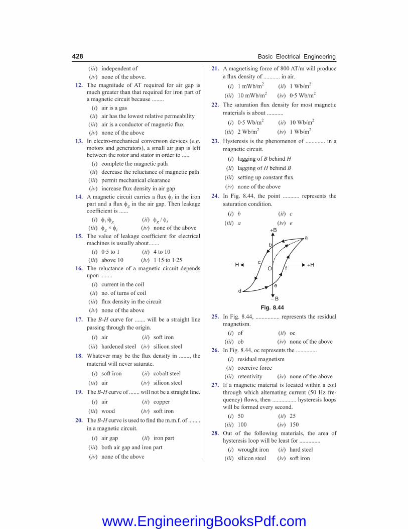
428 Basic Electrical Engineering
(iii) independent of (iv) none of the above. 12. The magnitude of AT required for air gap is
much greater than that required for iron part of a magnetic circuit because ........
(i) air is a gas (ii) air has the lowest relative permeability (iii) air is a conductor of magnetic flux (iv) none of the above 13. In electro-mechanical conversion devices (e.g.
motors and generators), a small air gap is left between the rotor and stator in order to .....
(i) complete the magnetic path (ii) decrease the reluctance of magnetic path (iii) permit mechanical clearance (iv) increase flux density in air gap 14. A magnetic circuit carries a flux φi in the iron
part and a flux φg in the air gap. Then leakage coefficient is ......
(i) φi /φg (ii) φg / φi (iii) φg × φi (iv) none of the above 15. The value of leakage coefficient for electrical
machines is usually about....... (i) 0·5 to 1 (ii) 4 to 10 (iii) above 10 (iv) 1·15 to 1·25 16. The reluctance of a magnetic circuit depends
upon ........ (i) current in the coil (ii) no. of turns of coil (iii) flux density in the circuit (iv) none of the above 17. The B-H curve for ....... will be a straight line
passing through the origin. (i) air (ii) soft iron (iii) hardened steel (iv) silicon steel 18. Whatever may be the flux density in ......., the
material will never saturate. (i) soft iron (ii) cobalt steel (iii) air (iv) silicon steel 19. The B-H curve of ....... will not be a straight line. (i) air (ii) copper (iii) wood (iv) soft iron 20. The B-H curve is used to find the m.m.f. of ........
in a magnetic circuit. (i) air gap (ii) iron part (iii) both air gap and iron part (iv) none of the above
21. A magnetising force of 800 AT/m will produce a flux density of ........... in air.
(i) 1 mWb/m2 (ii) 1 Wb/m2
(iii) 10 mWb/m2 (iv) 0·5 Wb/m2
22. The saturation flux density for most magnetic materials is about ...........
(i) 0·5 Wb/m2 (ii) 10 Wb/m2
(iii) 2 Wb/m2 (iv) 1 Wb/m2
23. Hysteresis is the phenomenon of ............. in a magnetic circuit.
(i) lagging of B behind H (ii) lagging of H behind B (iii) setting up constant flux (iv) none of the above 24. In Fig. 8.44, the point ........... represents the
saturation condition. (i) b (ii) c (iii) a (iv) e
Fig. 8.44
25. In Fig. 8.44, ................ represents the residual magnetism.
(i) of (ii) oc (iii) ob (iv) none of the above 26. In Fig. 8.44, oc represents the .............. (i) residual magnetism (ii) coercive force (iii) retentivity (iv) none of the above 27. If a magnetic material is located within a coil
through which alternating current (50 Hz fre-quency) flows, then ................ hysteresis loops will be formed every second.
(i) 50 (ii) 25 (iii) 100 (iv) 150 28. Out of the following materials, the area of
hysteresis loop will be least for .............. (i) wrought iron (ii) hard steel (iii) silicon steel (iv) soft iron
www.EngineeringBooksPdf.com

Magnetic Circuits 429
29. The materials used for the core of a good relay should have ............... hysteresis loop.
(i) large (ii) very large (iii) narrow (iv) none of the above
30. The magnetic material used for ............. should have a large hysteresis loop.
(i) transformers (ii) d.c. generators (iii) a.c. motors (iv) permanent magnets
Answers 1. (ii) 2. (iv) 3. (iii) 4. (i) 5. (ii) 6. (iv) 7. (iii) 8. (ii) 9. (ii) 10. (iv) 11. (ii) 12. (ii) 13. (iii) 14. (i) 15. (iv) 16. (iii) 17. (i) 18. (iii) 19. (iv) 20. (ii) 21. (i) 22. (iii) 23. (i) 24. (iii) 25. (iii) 26. (ii) 27. (i) 28. (iii) 29. (iii) 30. (iv)
www.EngineeringBooksPdf.com

Introduction Inthebeginningofnineteenthcentury,Oersteddiscoveredthatamagneticfieldexistsaroundacurrent-carryingconductor. Inotherwords,magnetismcanbecreatedbymeansofanelectriccurrent.Canamagneticfieldcreateanelectriccurrentinaconductor?In1831,MichaelFaraday,thefamousEnglishscientist,discoveredthat thiscouldbedone.Hedemonstratedthatwhenthemagneticfluxlinkingaconductorchanges,ane.m.f.isinducedintheconductor.Thisphenomenonisknownaselectromagnetic induction.ThegreatdiscoveryofelectromagneticinductionbyFaradaythroughaseriesofbrilliantexperimentshasbroughtarevolutionintheengineeringworld.Mostoftheelectricaldevices(e.g.electricgenerator,transformer,telephonesetc.)arebasedonthisprinciple.Inthischapter,weshallconfineourattentiontothevariousaspectsofeletromagneticinduction.
9.1. Electromagnetic Induction Whenthemagneticflux*linkingaconductorchanges,ane.m.f.isinducedintheconductor.Iftheconductorformsacompletelooporcircuit,acurrentwillflowinit.Thisphenomenonisknownas**electromagneticinduction. The phenomenon of production of e.m.f. and hence current in a conductor or coil when the magnetic flux linking the conductor or coil changes is called electromagnetic induction.
Fig. 9.1
Todemonstratethephenomenonofelectromagneticinduction,consideracoilCofseveralturnsconnectedtoacentrezerogalvanometerG asshowninFig.9.1.Ifapermanentmagnetismovedtowardsthecoil,itwillbeobservedthatthegalvanometershowsdeflectioninonedirection.Ifthemagnetismovedawayfromthecoil,thegalvanometeragainshowsdeflectionbutintheoppositedirection. In either case, the deflection will persist so long as the magnet is in motion.Theproductionofe.m.f.andhencecurrentinthecoilCisduetothefactthatwhenthemagnetisinmotion(towardsor away from the coil), the amount of flux linking the coil changes—the basic requirement forinducinge.m.f.inthecoil.Ifthemovementofthemagnetisstopped,thoughthefluxislinkingthe
* Magnetic lines of force form closed loops. Flux linking the conductormeans that the flux embraces it i.e. it encircles the conductor.
** Socalledbecauseelectricityisproducedfrommagnetism(i.e. electromagnetic)andthatthereisnophysicalconnection (induction) between themagneticfield and the conductor.
9Electromagnetic Induction
www.EngineeringBooksPdf.com

Electromagnetic Induction 431
coil,thereisno change in flux andhencenoe.m.f.isinducedinthecoil.Consequently,thedeflectionofthegalvanometerreducestozero. Thefollowingpointsmaybenotedcarefully: (i) The basic requirement for inducing e.m.f. in a coil is not the magnetic flux linking the coil
but the change in flux linking the coil. No change in flux, no e.m.f. induced in the coil. (ii) Thechangeinfluxlinkingthecoilcanbebroughtaboutintwoways.First,theconductors
(orcoils)aremovedthroughastationarymagneticfieldasisthecasewithd.c.generators.Secondly,theconductorsarestationaryandthemagneticfieldismovingasisthecasewitha.c.generators.Ineithercase,thebasicprincipleisthesamei.e.theamountoffluxlinkingtheconductors(orcoils)ischanged.
(iii) The e.m.f. and hence current in the conductors (or coils) will persist so long as the magnetic flux linking them is changing.
Note. Wehaveseenthatwhenmagneticfluxlinkingaconductorchanges,ane.m.f.isinducedinit.Anequivalentstatementislikethis:When a conductor cuts magnetic field lines , an e.m.f. is induced in it. If the conductormovesparalleltothemagneticfieldlines,noe.m.f.isinduced.Thisterminologyisveryhelpfulinvisualisingtheconceptofproductionofe.m.f.
9.2. Flux Linkages
The product of number of turns (N) of the coil and the magnetic flux (φ) linking the coil is called flux linkages i.e. Fluxlinkages = N φ Experimentsshowthatthemagnitudeofe.m.f.inducedinacoilisdirectlyproportionaltotherateofchangeoffluxlinkages.IfNisthenumberofturnsofthecoilandthemagneticfluxlinkingthecoilchanges(sayincreases)fromφ1 to φ2 in t seconds, then,
Induced e.m.f., e ∝ Rateofchangeoffluxlinkages
or e ∝ 2 1N Nt
φ − φ
9.3. Faraday’s Laws of Electromagnetic Induction Faradayperformedaseriesofexperimentstodemonstratethephenomenonofelectromagneticinduction.Hesummeduphisconclusionsintotwolaws,knownasFaraday’slawsofelectromagneticinduction. First Law.Ittellsusabouttheconditionunderwhichane.m.f.isinducedinaconductororcoilandmaybestatedasunder: When the magnetic flux linking a conductor or coil changes, an e.m.f. is induced in it. Itdoesnotmatterhowthechangeinmagneticfluxisbroughtabout.Theessenceofthefirstlawisthattheinducede.m.f.appearsinacircuitsubjectedtoachangingmagneticfield. Second Law. Itgivesthemagnitudeoftheinducede.m.f.inaconductororcoilandmaybestatedasunder: The magnitude of the e.m.f. induced in a conductor or coil is directly proportional to the rate of change of flux linkages i.e. Induced e.m.f., e ∝ 2 1N N
tφ − φ
or e = 2 1N Nkt
φ − φ
www.EngineeringBooksPdf.com

432 Basic Electrical Engineering
wherethevalueofkis*unityinSIunits.
\ e = 2 1N Nt
φ − φ
Indifferentialform,wehave,e = dNdtφ
Thedirectionofinducede.m.f.(andhenceofinducedcurrentifthecircuitisclosed)isgivenby Lenz’s law.Themagnitudeanddirectionofinducede.m.f.shouldbewrittenas:
e = dNdtφ− ...(i)
The minus sign on the R.H.S. represents Lenz’s law mathematically.InSIunits,e is measured involts,φ in webers and t in seconds.
9.4. Direction of Induced E.M.F. and Current Thedirectionofinducede.m.f.andhencecurrent(ifthecircuitisclosed)canbedeterminedbyoneofthefollowingtwomethods: (i) Lenz’sLaw (ii) Fleming’sright-handrule (i) Lenz’s law. EmilLenz, aGerman scientist, gave the following simple rule (known asLenz’slaw)tofindthedirectionoftheinducedcurrent:The induced current will flow in such a direction so as to oppose the cause that produces it i.e. the induced current will set up magnetic flux to oppose the change in flux. Note that Lenz’s law is reflected mathematically in the minus sign on the R.H.S. of Faraday’s second law viz. e = − N dφldt. Thenegativesignsimplyremindsusthattheinducedcurrentopposes the changing magnetic fieldthatcausedtheinducedcurrent.The negative sign has no other meaning. LetusapplyLenz’s lawtoFig.9.2.HeretheN-poleof themagnet isapproachingacoilofseveralturns.AstheN-poleofthemagnetmovestowardsthecoil,themagneticfluxlinkingthecoilincreases.Thereforeane.m.f.andhencecurrentisinducedinthecoilaccordingtoFaraday’slawsofelectromagneticinduction.AccordingtoLenz’slaw,thedirectionoftheinducedcurrentwillbesuchsoastoopposethecausethatproducesit.Inthepresentcase,thecauseoftheinducedcurrentistheincreasingmagneticfluxlinkingthecoil.Therefore,theinducedcurrentwillsetupmagneticfluxthatopposestheincreaseinfluxthroughthecoil.ThisispossibleonlyifthelefthandfaceofthecoilbecomesN-pole.Onceweknowthemagneticpolarityofthecoilface,thedirectionoftheinducedcurrentcanbeeasilydeterminedbyapplyingright-handruleforthecoil.Ifthemagnetismovedawayfromthecoil,thenbyLenz’slaw,thelefthandfaceofthecoilwillbecomeS-pole.Therefore,byright-handruleforthecoil,thedirectionofinducedcurrentinthecoilwillbeoppositetothatinthefirstcase.
Fig. 9.2
* One volt (SI unit of e.m.f.) has been so defined that the value of k becomes unity.Thus 1V is said to beinduced in a coil if theflux linkages changeby1Wb-turn in 1 second.
Here, N φ2 − N φ1=1Wb-turn, t = 1 s ande = 1 volt \ 1= 11
k × or k = 1.
www.EngineeringBooksPdf.com

Electromagnetic Induction 433
ItmaybenotedherethatLenz’slawdirectlyfollowsfromthelawofconservationofenergyi.e. inordertosetupinducedcurrent,someenergymustbeexpended.Intheabovecase,forexample,when the N-poleofthemagnetisapproachingthecoil,theinducedcurrentwillflowinthecoilinsuchadirectionthattheleft-handfaceofthecoilbecomesN-pole.Theresultisthatthemotionofthemagnetisopposed.Themechanicalenergyspentinovercomingthisoppositionisconvertedintoelectricalenergywhichappearsinthecoil.ThusLenz’slawisconsistentwiththelawofconserva-tion of energy. (ii) Fleming’s Right-Hand Rule. Thislawisparticularlysuitabletofindthedirectionoftheinducede.m.f.andhencecurrentwhentheconductormovesatrightanglestoastationarymagneticfield.Itmaybestatedasunder: Stretch out the forefinger, middle finger and thumb of your right hand so that they are at right angles to one another. If the forefinger points in the direction of magnetic field, thumb in the direction of motion of the conductor, then the middle finger will point in the direction of induced current.
Fig. 9.3 Consider a conductor AB movingupwardsatrightanglestoauniformmagneticfieldasshowninFig.9.3.ApplyingFleming’sright-handrule,itisclearthatthedirectionofinducedcurrentisfrom B to A.Ifthemotionoftheconductorisdownward,keepingthedirectionofmagneticfieldunchanged,thenthedirectionofinducedcurrentwillbefromA to B.
Example 9.1. A coil of 200 turns of wire is wound on a magnetic circuit of reluctance 2000 AT/Wb. If a current of 1A flowing in the coil is reversed in 10 ms, find the average e.m.f. induced in the coil. Solution. Fluxinthecoil = m.m.f. 200 1 0 1 Wb
reluctance 2000×= = ⋅
Whenthecurrent(i.e.1A)inthecoilisreversed,fluxthroughthecoilisalsoreversed.
e = dNdtφ
Here, N =200; dφ = 0·1−(−0·1)=0·2mWb;dt=10×10−3s
\ e = 3
30 2 1020010 10
−
−⋅ ××
×=4 V
Example 9.2. The field winding of a 4-pole d.c. generator consists of 4 coils connected in series, each coil being wound with 1200 turns. When the field is excited, there is a magnetic flux of 0·04 Wb/pole. If the field switch is opened at such a speed that the flux falls to the residual value of 0·004 Wb/pole in 0·1 second, calculate the average value of e.m.f. induced across the field winding ter-minals. Solution.Totalno.ofturns, N= 1200×4=4800 Totalinitialflux =4×0·04=0·16Wb
www.EngineeringBooksPdf.com

434 Basic Electrical Engineering
Totalresidualflux = 4×0·004=0·016Wb Changeinflux, dφ = 0·16−0·016=0·144Wb Timetaken,dt = 0·1second
\ Induced e.m.f., e = 0.14448000.1
dNdtφ = × =6912 V
Example 9.3. A fan blade of length 0·5m rotates perpendicular to a magnetic field of 5×10⁻⁵T. If the e.m.f. induced between the centre and end of the blade is 10−2V, find the rate of rotation of the blade. Solution. Let nbetherequirednumberofrotationsinonesecond.Themagnitudeofinducede.m.f.isgivenby; e = ( )
d d dAN N BA Bdt dt dtφ = = ( N=1)
HeredAistheareasweptbythebladeinonerevolutionanddtisthetimetakentocompleteonerevolution. Now e=10−2V;B=5×10⁻⁵T; dA=πr2=π×(0·5)2 m2; dt= 1 s
n
\ 10−2 = ( )2
5 0 55 10
1/ n− π × ⋅
× ×
or n = ( ) ( )2
25
10
5 10 0 5
−
−× × π × ⋅=254.7 rev / second
DoublingthespeedofrotationofthebladewoulddoublethevalueofdA/dt.Hence,thee.m.f.inducedwouldbedoubled. Example 9.4. A coil of mean area 500 cm2 and having 1000 turns is held perpendicular to a uniform field of 0.4 gauss. The coil is turned through 180° in 1/10 second. Calculate the average induced e.m.f. Solution. φ = NBAcosθ Whentheplaneofthecoilisperpendiculartothefield,θ=0°.Whenthecoilisturnedthrough180°,θ=180°.Therefore,initialfluxlinkedwiththecoilis φ1 = NBAcos0°=NBA Fluxlinkedwithcoilwhenturnedthrough180°is φ2 = NBAcos180°=−NBA Changeinfluxlinkingthecoilis ∆φ = φ2−φ1=(–NBA)–(NBA)=–2NBA
\ Averageinducede.m.f.,e= 2NBAt t
∆φ− =∆ ∆
HereN=1000;B=0.4gauss=0.4×10⁻⁴T;A=500×10–4 m2 ;∆t=0.1s
\ e = 4 42 1000 (0.4 10 ) 500 10
0.1
− −× × × × ×=0.04 V
Example 9.5. The magnetic flux passing perpendicular to the plane of the coil and directed into the paper (See Fig. 9.4) is varying according to the relation : φB = 6t2 + 7t + 1 where φB is in mWb and t in seconds. (i) What is the magnitude of induced e.m.f. in the loop when t = 2 seconds ? (ii) What is the direction of current through the resistor R ? Solution. φB = (6t2 + 7t+1)mWb=(6t2 + 7t+1)×10−3 Wb (i)Magnitudeofinducede.m.f.is Fig. 9.4
www.EngineeringBooksPdf.com

Electromagnetic Induction 435
e = Bd ddt dtφ = (6t2 + 7t+1)×10–3=(12t+7)×10–3V
Att=2sec,e = (12×2+7)×10–3=31×10–3V=31 mV (ii) AccordingtoLenz’slaw,thedirectionofinducedcurrentwillbesuchsoastoopposethe
changeinflux.Thismeansthatdirectionofcurrentintheloopwillbesuchastoproducemagneticfieldoppositetothegivenfield.Forthis(i.e.,upwardfield),thecurrentinducedintheloopwillbeanticlockwise.Therefore,current in resistor R will be from left to right.
Tutorial Problems 1. Asquarecoilofside5cmcontains100loopsandispositionedperpendiculartoauniformmagnetic
fieldof0.6T.Itisquicklyremovedfromthefield(movingperpendiculartothefield)toaregionwheremagneticfieldiszero.Ittakes0.1sforthewholecoiltoreachfield-freeregion.Ifresistanceofthecoilis100Ω,howmuchenergyisdissipatedinthecoil? [2·3×10–3J]
2. Aflatsearchcoilcontaining50turnseachofarea2×10–4 m2isconnectedtoagalvanometer;thetotalresistanceofthecircuitis100Ω.Thecoilisplacedsothatitsplaneisnormaltoamagneticfieldoffluxdensity0·25T.
(i) What is the change inmagneticflux linking the circuitwhen the coil ismoved to a regionofnegligiblemagneticfield?
(ii) Whatchargepassesthroughthegalvanometer? [(i) 2·5×10–3 Wb (ii) 25 µC] 3. Themagneticfluxpassingperpendiculartotheplaneofacoilanddirectedintotheplaneofthepaperis
varyingaccordingtothefollowingequation: φ = 5t2+6t +2 where φ is in mWb and tinseconds.Findthee.m.f.inducedinthecoilatt = 1s. [16mV] 4. Acoilhasanareaof0.04m2andhas1000turns.Itissuspendedinamagneticfieldof5×10–5 Wb/m2
perpendiculartothefield.Thecoilisrotatedthrough90ºin0·2s.Calculatetheaveragee.m.f.inducedinthecoilduetorotation. [0·01V]
5. Agramophonediscofbrassofdiameter30cmrotateshorizontallyattherateof100/3revolutionsperminute. If theverticalcomponentofearth’sfield is0·01T,calculate thee.m.f. inducedbetween thecentre and the rim of the disc. [3·9 × 10–4 V]
9.5. Induced E.M.F. Whenthemagneticfluxlinkingaconductor(orcoil)changes,ane.m.f.isinducedinit.Thischangeinfluxlinkagescanbebroughtaboutinthefollowingtwoways: (i) Theconductorismovedinastationarymagneticfieldinsuchawaythatthefluxlinkingit
changesinmagnitude.Thee.m.f.inducedinthiswayiscalleddynamically induced e.m.f. (asinad.c.generator).Itissocalledbecausee.m.f.isinducedintheconductorwhichisinmotion.
(ii) The conductor is stationary and themagnetic field is moving or changing. The e.m.f.inducedinthiswayiscalledstatically induced e.m.f. (asinatransformer).Itissocalledbecause the e.m.f. is induced in a conductor which is stationary.
It may be noted that in either case, the magnitude of induced e.m.f. is given by Ndφ/dt or derivable from this relation.
9.6. Dynamically Induced E.M.F. Considerasingleconductoroflengthlmetresmovingat*rightanglestoauniformmagneticfieldofB Wb/m2withavelocityofv m/s [SeeFig.9.5(i)].Supposetheconductormovesthroughasmalldistancedx in dt seconds.Thenareasweptbytheconductoris=l × dx.* If the conductor ismoved parallel to themagnetic field, therewould be no change in flux and hence no
e.m.f.wouldbe induced.
www.EngineeringBooksPdf.com

436 Basic Electrical Engineering
Fig. 9.5
\ Fluxcut,dφ = Fluxdensity×Areaswept=B l dx Wb AccordingtoFaraday’slawsofelectromagneticinduction,themagnitudeofe.m.f.e induced in theconductorisgivenby; e = dN
dtφ =
B l dxdt ( N=1)
\ e = B l vvolts ( dx / dt=v) Special case. Iftheconductormovesatangleθtothemagneticfield[SeeFig.9.5(ii)], then the velocityatwhichtheconductormovesacrossthefieldis*vsinθ. \ e = B l v sinθ Thedirectionoftheinducede.m.f.canbedeterminedbyFleming’sright-handrule. Example 9.6. An aircraft has a wing span of 56 m. It is flying horizontally at a speed of 810 km/hr and the vertical component of earth’s magnetic field is 4×10⁻⁴ Wb/m2. Calculate the potential difference between the wing tips of the aircraft. Solution. Inducede.m.f.=B lv
Here B=4×10⁻⁴ Wb/m2;l=56m; v= 810 1000 225 m/s3600× =
\ Inducede.m.f. = (4×10−4)×56×(225)=5·04Vor Potentialdifference = 5·04 V Example 9.7. A d.c. generator consists of conductors lying in a radius of 10 cm and the effective length of a conductor in a constant radial field of strength 0·9 Wb/m2 is 12 cm. The armature rotates at 1400 r.p.m. Given that the generator has 152 conductors in series, calculate the voltage being generated. Solution. Sincethemagneticfieldisradial,theconductorscutthemagneticlinesofforceatrightangles. Velocity,v = ω×r=
260
N rπ × = 20 1 14 66 m s
60π ×1400 × ⋅ = ⋅
Voltagegeneratedineachconductor=B lv=0·9×0·12×14·66=1·583V Voltagegeneratedin152conductorsinseries = 1·583×152=240·6 V Note that effective length (l) is thatportionof the conductorwhich takespart in the actualcuttingofmagneticfluxlines.* The componentv cos θ is parallel tomagneticfield and hence no e.m.f. is induced in the conductor
due to this component.
www.EngineeringBooksPdf.com

Electromagnetic Induction 437
Example 9.8. A square metal wire loop of side 10 cm and resistance 1 Ω is moved with a constant velocity v0 in a uniform magnetic field of induction B = 2 Wb/m2 as shown in Fig. 9.6. The magnetic field lines are perpendicular to the plane of the loop directed into the paper. The loop is connected to a network of resistors each of value 3 Ω. The resistances of lead wires OS and PQ are negligible. What should be the speed v0 of the loop so as to have a steady current of 1 mA in the loop ? Also indicate the direction of current in the loop. Solution. Weshallfirstfindtheequivalentresistanceofthenetwork.ItisclearthatnetworkisabalancedWheatstonebridge.Therefore,theresistanceinthebranchACisineffective.Theequiva-lentresistanceR′ofthenetworkisgivenby;
1R′ =
1 1 16 6 3
+ = or R′=3Ω
Theresistanceoftheloopis1Ω. \ Effective resistance of the circuit, R=R′+1=3+1=4Ω E.M.F.inducedintheloop, e = Bl v0
Currentintheloop,i = 0BlveR R
= \ Speedoftheloop, v0=iRBl
Here i=1mA=10–3A ; R=4Ω ; B=2Wb/m2 ; l=0.1m
\ v0 = 310 4
2 0.1
− ×× =2×10⁻² ms–1=2 cm/second
AccordingtoFleming’sright-handrule,directionofinducedcurrentisclockwise from O to P. Example 9.9. A wheel with 10 metal spokes each 0.5 m long is rotated with a speed of 120 r.p.m. in a plane normal to earth’s magnetic field at a place. If the magnitude of the field is 0.4 G, what is the magnitude of induced e.m.f. between the axle and rim of the wheel ? Solution. Lengthofspoke,l = radiusr=0.5m Frequencyofrotation,n = 120r.p.m.=2r.p.s. Magneticfluxdensity,B = 0.4G=0.4×10⁻⁴T Angularfrequency,ω = 2πn=2π×2=4πrads–1
Asthewheelrotates,thelinearvelocityofspokeendattherim=ωrandlinearvelocityofspokeendattheaxle=0.
\ Averagelinearvelocity,v=0 1
2 2r r+ ω = ω
Inducede.m.f.acrosstheendsofeachspokeis
e = Bl v=(B)(r) 21 12 2
r B r ω = ω
or e = 21 12 2
B r ω = (0.4×10–4)×(0.5)2×4π=6.28 × 10⁻⁵ V
Oneendofall10spokesisconnectedtotherimandtheotherendtotheaxle.Therefore,thespokesareconnectedinparallel.Asaresult,e.m.f.betweenrimandaxleisequaltothee.m.f.acrosstheendsofeachspoke. Example 9.10. A conductor 10 cm long and carrying a current of 50 A lies perpendicular to a field of strength 1000 A/m. Calculate : (i) the force acting on the conductor.
Fig. 9.6
www.EngineeringBooksPdf.com

438 Basic Electrical Engineering
(ii) the mechanical power to move this conductor against the force with a speed of 1 m/s. (iii) e.m.f. induced in the conductor. Solution. (i) F=BIl. Now H=1000A/m \ B = µ0H=4π×10
–7×1000=4π×10–4 Wb/m2
\ F = (4π×10–4)×50×0.1=6.28 × 10⁻³ N (ii)Mechanicalpowerrequiredisgivenby; P = F×v=6.28×10–3×1=6.28 × 10⁻³ W (iii) E.M.F.inducedintheconductorisgivenby; e = Blv=(4π×10–4)×0.1×1=4π× 10–5 V Notethatelectricpowerdeveloped=eI=(4π×10–5)×50=6.28×10⁻³W.Thisisequaltothemechanicalinputpower.Therefore,lawofconservationofenergyisobeyed.
Tutorial Problems 1. Acopperdisc40cm indiameter is rotatedat3000 r.p.m.onahorizontalaxisperpendicular toand
throughthecentreofthedisc,theaxislyinginthemagneticmeridian.Twobrushesmakecontactwiththedisc,oneat theedgeand theotherat thecentre. If thehorizontal componentof earth’sfieldbe 0.02mWb/m2,calculatethee.m.f.inducedbetweenthebrushes. [0.12 mV]
2. Ameterdrivingmotorconsistsofahorizontaldiscofaluminium20cmindiameter,pivotedonaverticalspindleandlyinginapermanentmagneticfieldofdensity0.3Wb/m2.Thecurrentflowisradialfromthespindletothecircumferenceofthedisc.Thecircuitresistanceis0.225Wandap.d.of2.3Visrequiredtopassacurrentof10Athroughthemotor.Calculatetherotationalspeedofthediscandthepowerlostin friction. [319 r.p.m. ; 0.5 W]
3. Iftheverticalcomponentofearth’smagneticfieldbe4×10–5 Wb/m2,thenwhatwillbetheinducedpotentialdifferenceproducedbetweentherailsofametre-gaugewhenatrainisrunningonthemwithaspeedof36km/hr? [4 × 10⁻⁴ V]
9.7. Statically Induced E.M.F. Whentheconductorisstationaryandthefieldismovingorchanging,thee.m.f.inducedintheconductoriscalledstaticallyinducede.m.f.Astaticallyinducede.m.f.canbefurthersub-dividedinto: 1.Self-inducede.m.f. 2.Mutuallyinducede.m.f. 1. Self-induced e.m.f. The e.m.f. induced in a coil due to the change of its own flux linked with it is called self-induced e.m.f. Whenacoiliscarryingcurrent(SeeFig.9.7),amagneticfieldisestablishedthroughthecoil.Ifcurrentinthecoilchanges,thenthefluxlinkingthecoilalsochanges.Henceane.m.f.(=N dφ/dt) is inducedinthecoil.This is known as self-induced e.m.f. Thedirection of this e.m.f. (by Lenz’s law) issuch so as to oppose the cause producingit,namelythechangeofcurrent(andhencefield)inthecoil.Theself-inducede.m.f.willpersist so long as the current in the coil ischanging.Thefollowingpointsareworthnoting: (i) Whencurrentinacoilchanges,theself-inducede.m.f.opposesthechangeofcurrentinthecoil.Thispropertyofthecoilisknownasitsself-inductance or inductance.
Fig. 9.7
www.EngineeringBooksPdf.com

Electromagnetic Induction 439
(ii) The self-induced e.m.f. (and hence inductance) does not prevent the current from changing ; it serves only to delay the change. Thusaftertheswitchisclosed(SeeFig.9.7),thecurrentwillrisefromzeroamperetoitsfinalsteadyvalueinsometime(afractionofasecond).Thisdelayisduetotheself-inducede.m.f.ofthecoil. 2. Mutually induced e.m.f. The e.m.f. induced in a coil due to the changing current in the neighbouring coil is called mutually induced e.m.f. ConsidertwocoilsA and BplacedadjacenttoeachotherasshowninFig.9.8.ApartofthemagneticfluxproducedbycoilApassesthroughorlinkswithcoilB.ThisfluxwhichiscommontoboththecoilsA and Biscalledmutual flux (φm).IfcurrentincoilAisvaried,themutualfluxalsovariesandhencee.m.f.isinducedinboththecoils.Thee.m.f.inducedincoilAiscalledself-inducede.m.f.asalreadydiscussed.Thee.m.f.inducedincoilBisknownasmutually induced e.m.f.
Fig. 9.8
Themagnitudeofmutuallyinducede.m.f.isgivenbyFaraday’slawsi.e. eM = NB dφm/dt where NBisthenumberofturnsofcoilB and dφm/dt istherateofchangeofmutualfluxi.e.fluxcommontoboththecoils.Thedirectionofmutuallyinducede.m.f.(byLenz’slaw)isalwayssuchsoastoopposetheverycauseproducingit.Thecauseproducingthemutuallyinducede.m.f.incoilB is the changingmutualfluxproducedbycoilA.Hencethedirectionofinducedcurrent(whenthecircuitiscompleted)incoilBwillbesuchthatthefluxsetupbyitwillopposethechangingmutualfluxproducedbycoilA. Thefollowingpointsmaybenotedcarefully: (i) Themutuallyinducede.m.f.incoilBpersistssolongasthecurrentincoilA is changing. If
currentincoilAbecomessteady,themutualfluxalsobecomessteadyandmutuallyinducede.m.f.dropstozero.
(ii) Thepropertyoftwoneighbouringcoilstoinducevoltatgeinonecoilduetothechangeofcurrentintheotheriscalledmutual inductance.
9.8. Self-inductance (L) The property of a coil that opposes any change in the amount of current flowing through it is called its self-inductance or inductance. Thisproperty(i.e. inductance)isduetotheself-inducede.m.f.inthecoilitselfbythechangingcurrent.Ifthecurrentinthecoilisincreasing,theself-inducede.m.f.issetupinsuchadirectionsoastoopposetheriseofcurrenti.e.directionofself-inducede.m.f.isoppositetothatoftheappliedvoltage.Similarly,ifthecurrentinthecoilisdecreasing,self-inducedvoltagewillbesuchsoastoopposethedecreaseincurrenti.e.self-inducede.m.f.willbeinthesamedirectionastheappliedvoltage.Itmaybenotedthatself-inductancedoesnotpreventthecurrentfromchanging;itservesonlytodelaythechange.
www.EngineeringBooksPdf.com

440 Basic Electrical Engineering
Factors affecting inductance. The greater the self-induced voltage, the greater the self-inductance of the coil and hence larger is the opposition to the changing current.According toFaraday’slawsofelectromagneticinduction,inducedvoltageinacoildependsuponthenumberofturns(N)andtherateofchangeofflux(dφ/dt)linkingthecoil.Hence,theinductanceofacoildependsuponthesefactors,viz : (i) Shapeandnumberofturns. (ii) Relativepermeabilityofthematerialsurroundingthecoil. (iii) Thespeedwithwhichthemagneticfieldchanges. In fact, anything that affects magnetic field also affects the inductance of the coil. Thus,increasingthenumberofturnsofacoilincreasesitsinductance.Similarly,substitutinganironcorefor air core increases its inductance. It may be noted carefully that inductance makes itself felt in a circuit (or coil) only when there is a changing current. Thus,althoughacircuitelementmayhaveinductancebyvirtueofitsgeometricalandmagneticproperties, itspresence in thecircuit isnotexhibitedunless there isachangeofcurrentinthecircuit.Forexample,ifasteadydirectcurrent(d.c.)isflowinginacircuit,therewillbenoinductance.However,whenalternatingcurrentisflowinginthesamecircuit,thecurrentisconstantlychangingandhencethecircuitexhibitsinductance. Note.Theself-inductanceofacoilopposesthechangeofcurrent(increaseordecrease)throughthecoil.Thisoppositionoccursbecauseachangingcurrentproducesself-inducede.m.f.(e)whichopposesthechangeofcurrent.Forthisreason,self-inductance of a coil is called electrical inertia of the coil.
9.9. Magnitude of Self-induced E.M.F. ConsideracoilofN turns carrying a current of Iamperes.Ifcurrentinthecoilchanges,thefluxlinkagesofthecoilwillalsochange.Thiswillsetupaself-inducede.m.f.einthecoilgivenby;
e = ( )d dN Ndt dtφ = φ
Sincefluxisduetocurrentinthecoil,itfollowsthatfluxlinkages(= Nφ)willbeproportionaltoI. \ e = d
dt (Nφ) ∝ dIdt
\ e = Constant× dIdt
or e = dILdt
(in magnitude) ...(i)
where Lisaconstantcalledself-inductance or inductanceofthecoil.Theunitofinductanceishenry(H).Ifineq.(i) above, e =1volt,dI/dt=1A/second,thenL=1H. Hence a coil ( or circuit ) has an inductance of 1 henry if an e.m.f. of 1 volt is induced in it when current through it changes at the rate of 1 ampere per second. Note.Themagnitudeofself-inducede.m.f.ise=LdI/dt.However,themagnitudeanddirectionofself-inducede.m.f.shouldbewrittenas: e = – dIL
dt Theminussignisbecausetheself-inducede.m.f.tendstosendcurrentinthecoilinsuchadirectionsoas to producemagneticfluxwhichopposesthechangeinfluxproducedbythechangeincurrentinthecoil.Infact,minussignrepresentsLenz’slawmathematically.
9.10. Expressions for Self-inductance Theself-inductance(L)ofacircuitorcoilcanbedeterminedbyoneof thefollowingthreeways:
www.EngineeringBooksPdf.com

Electromagnetic Induction 441
(i) First Method.Ifthemagnitudeofself-inducede.m.f.(e) and the rate of change of current (dI/dt)areknown,theninductancecanbedeterminedfromthefollowingrelation:
e = dILdt
\ L = ( )
edI dt ...(i)
(ii) Second Method. Ifthefluxlinkagesofthecoilandcurrentareknown,theninductancecanbedeterminedasunder: e = dI dL
dt dt= (LI )
Also e = d dNdt dtφ = (N φ)
Fromthetwoexpressions,wehave,
L I = N φ
\ L = NIφ ...(ii)
Thus,inductanceisthefluxlinkagesofthecoilperampere.IfN φ = 1 Wb-turn and I = 1A,then L =1H. Hence a coil has an inductance of 1 henry if a current of 1 A in the coil sets up flux linkages of 1 Wb-turn. Note. Relation (ii) above reveals that inductancedependsupon the ratioφ/I. Therefore, inductance isconstantonlywhenthefluxchangesuniformlywithcurrent.Thisconditionismetonlywhenthefluxpathisentirelycomposedofnon-magneticmateriale.g.air.Butwhenthefluxpathisthroughamagneticmaterial(e.g.coilwoundover ironbar), inductanceof thecoilwillbeconstantonlyover the linearportionof themagnetisation curve. (iii) Third Method. Theinductanceofamagneticcircuitcanbefoundintermsofitsphysicaldimensions.Consideraniron-cored*solenoidofdimensionsasshowninFig.9.9.Inductanceofthesolenoidisgivenby[fromexp.(ii)above];
L = dNdI
φ
Now φ = 0
m.m.f.reluctance / r
N Il a
=µ µ
Differentiating φ w.r.t. I, we get,
ddI
φ = 0 rN alµ µ
\ L = ( )0 rN a
Nlµ µ
or L = 2
0 rN alµ µ
...(iii)
= 2
0/ r
Nl a µ µ = ( )
2
ReluctanceN
S ...(iv)
Thus,inductancecanbedeterminedbyusingtherelation(iii)or(iv). It is important to note [See relation (iv)] that inductance is directly proportional to turns squared and inversely proportional
* Solenoidisanimportantwindingarrangement,beingsimpletomanufacture,it isfoundinrelays,inductors,small transformers in the formconsidered.
Fig. 9.9
www.EngineeringBooksPdf.com

442 Basic Electrical Engineering
to the reluctance of the magnetic path.Thesmallerthereluctanceofthemagneticpath,thelargerthe inductance and vice-versa. For this reason, an iron-cored coil hasmore inductance than theequivalentair-coredcoil. Example 9.11. A coil wound on an iron core of permeability 400 has 150 turns and a cross-sectional area of 5 cm2. Calculate the inductance of the coil. Given that a steady current of 3 mA produces a magnetic field of 10 lines/cm2 when air is present as the medium.
Solution. µi = Flux density in ironFlux density in air 10
iB=
\ Bi = 10×µi=10×400=4000lines/cm2
Fluxproducedby3mAcurrentintheironcoreis φ = Bi × a=4000×5=20,000lines=2×10⁻⁴Wb
\ L = 4
3
150 2 10
3 10
NI
−
−φ × ×=
×= 10 H
Example 9.12. A solenoid with 900 turns has a total flux of 1.33 × 10⁻⁷ Wb through its air core when the coil current is 100 mA. If the flux takes 75 ms to grow from zero to its maximum level, cal-culate the inductance of the coil. Also, calculate the induced e.m.f. in the coil during the flux growth. Solution.Themagnitudeofinducede.m.f.isgivenbythefollowingtwoexpressions:
e = dILdt ;e=
dNdtφ
\ dILdt =
dNdtφ or L= dN
dIφ
Here N=900;dφ = 1.33×10⁻⁷Wb;dt=75ms=75×10–3s; dI=100mA = 100×10–3A
\ L = 7
3
1.33 10900
100 10
−
−×××
=1.2×10⁻³H=1.2 mH
Induced e.m.f., e = dNdtφ =
7
3
1.33 10900
75 10
−
−××
×=1.6×10⁻³V=1.6 mV
Example 9.13. An air-cored choke is designed to have an inductance of 20H when operating at a flux density of 1 Wb/m2 ; the corresponding relative permeability of iron core is 4000. Determine the number of turns in the winding ; given that the flux path has a mean length of 22 cm in the iron core and 1 mm in air gap and that its cross-section is 10 cm2. Solution. L = N2/STwhere STisthetotalreluctanceofthemagneticpath.
ST = Siron + Sair=0 0
iron air
r r
l la a
+µ µ µ µ
= ( ) ( )4 7 4 7
0 22 0 001
10 10 4 10 4000 10 10 4 10 1− − − −⋅ ⋅+
× × π× × × × π× ×
= 43767+795774=839541AT/Wb Now L = N2/ST
\ N = 20 839541TL S = × =4097 turns Example 9.14. An iron rod, 1 cm diameter and 50 cm long is formed into a closed ring and uniformly wound with 400 turns of wire. A direct current of 0·5 A is passed through the winding and produces a flux density of 0·75 Wb/m2. If all the flux links with every turn of the winding, calculate
www.EngineeringBooksPdf.com

Electromagnetic Induction 443
(i) the relative permeability of iron (ii) the inductance of the coil (iii) the average value of e.m.f. induced when the interruption of current causes the flux in the iron to decay to 20% of its original value in 0·01 second. Solution. (i) H = 400 0 5 400 AT/m
0 5N I
l× ⋅= =⋅
µr = 70
0.75
4 10 400
BH −=
µ π × ×=1492
(ii) φ = ( )220 75 1 104
B a −π× = ⋅ × × =0·589×10−4 Wb
\ L = ( ) 4400 0 589 10
0 5N
I
−× ⋅ ×φ =⋅ =0.0471 H
(iii) Changeinflux, dφ = 80%oforiginalflux=0·8×0·589×10−4=0·47×10−4 Wb
\ e = 40.47 10
4000.01
dNdt
−×φ = × =1.88 V
Example 9.15. A circuit has 1000 turns enclosing a magnetic circuit 20 cm2 in section. With 4A, the flux density is 1 Wb/m2 and with 9A, it is 1.4 Wb/m2. Find the mean value of the inductance between these current limits and the induced e.m.f. if the current falls from 9A to 4A in 0·05 seconds.
Solution. L = ( )d d dBN N BA NAdI dI dI
φ = =
Here N=1000 ; dB=1·4–1=0·4Wb/m2 ; dI=9–4=5A
\ L = (1000)×(20×10–4)× 0.45
=0.16 H
Also e = 50·160·05
dILdt
= × =16 V
Example 9.16. A single element has the current and voltage functions graphed in Fig. 9.10 (i) and (ii). Determine the element.
Fig. 9.10
Solution.Fromi –t and V –tgraphoftheelement,weobservethat: Between 0 – 2 ms ;di=10A;dt=2ms;V=15volts
\ didt = 3
10A
2 10 s−×=5000A/s.Now,L= V
di dt =15
5000=3×10⁻³H=3mH
Between 4 – 6 ms ;di=–20A;dt=2ms;V=–30volts
\ didt = 3
20A
2 10 s−−×
=–10,000A/s.Now,L= Vdi dt =
3010,000−
− =3×10⁻³H=3mH
Note that when current is constant, di/dt=0sothatvoltageacrossL is zero. Hence, the element is 3 mH inductor.
www.EngineeringBooksPdf.com

444 Basic Electrical Engineering
Example 9.17. A 300-turn coil has a resistance of 6 Ω and an inductance of 0·5 H. Determine the new resistance and new inductance if one-third of the turns are removed. Assume all the turns have the same circumference. Solution. Astheresistanceofacoilisdirectlyproportionaltoitslength, \ R1/R2 = N1/N2 or 6/R2=300/200
\ R2 = 2006300
× =4 W
Also 1
2
LL =
2122
/
/
N SN S
or 2
22
(300)0.5
(200)L=
\ L2 = 2
2
(200)0.5
(300)× =0·22 H
Example 9.18. A battery of 24 V is connected to the primary (coil 1) of a two-winding trans-former as shown in Fig. 9.11 and the secondary (coil 2) is open-circuited. The coil parameters are : R1 = 10 Ω R2 = 30 Ω N1 = 100 turns N2 = 160 turns φ1 = 0·01 Wb φ2 = 0·008 Wb Calculate (i) the self-inductance of coil 1 (ii) the mutual inductance (iii) the coefficient of coupling and (iv) the self-inductance of coil 2.
Fig. 9.11
Solution. (i) I1 = V/R1=24/10=2·4A
\ L1 = 1 1
1
100 0.012·4
NI
φ ×= =0.417 H
(ii) M = 2 2
1
160 0.0082·4
NI
φ ×= =0.533 H
(iii) k = 0·008/0·01=0·8
(iv) M = 1 2k L L or 0·533= 20·8 0·417 L× \ L2=1·064 H Example 9.19. A coil of 1000 turns is wound on a laminated core of steel having a cross-section of 5 cm2. The core has an air gap of 2 mm cut at right angle. What value of current is required to have an air gap flux density of 0.5 T? Permeability of steel may be taken as infinity. Determine the coil inductance. Solution. Bg=0.5T;a=5×10
–4 m2;N=1000turns;lg=2×10⁻³m;µr=∞
TotalATrequired = Hili + Hglg=0 0
g gi g
r
B Bl l+
µ µ µ
= 0
0 gg
Bl+
µ = 37
0.50 2 104 10
−−+ × ×
π ×=796AT (µr=∞)
www.EngineeringBooksPdf.com

Electromagnetic Induction 445
Now NI = 796 \ I= 796N = 796
1000=0.796 A
Inductanceofcoil,L = NIφ =
( )gN B aI
× ×=
41000 (0.5 5 10 )0.796
−× × ×=0.314 H
Tutorial Problems 1. Acurrentof2·5Aflowsthrougha1000-turncoilthatisair-cored.Thecoilinductanceis0·6H.What
magneticfluxissetup? [1·5 m Wb] 2. A2000-turncoilisuniformlywoundonaneboniteringofmeandiameter320mmandcross-sectional
area400mm2.Calculatetheinductanceofthetoroidsoformed. [2 mH] 3. Acoilhasself-inductanceof10H.Ifacurrentof200mAisreducedtozeroinatimeof1ms,findthe
averagevalueofinducede.m.f.acrosstheterminalsofthecoil. [2000 V] 4. Acoilconsistsof750turnsandacurrentof10Ainthecoilgivesrisetoamagneticfluxof1200µWb.
Calculate the inductanceof the coil anddetermine the average e.m.f. induced in the coilwhen thiscurrentisreversedin0·01second. [0·09 H ; 180 V]
5. Calculatetheinductanceofasolenoidof2000turnswounduniformlyoveralengthof50cmonacy-lindricalpapertube4cmindiameter.Themediumisair. [12·62 mH]
6. Acircularironringofmeandiameter100mmandcross-sectionalarea500mm2has200turnsofwireuniformlywoundaroundthecircumference.Iftherelativepermeabilityofironisassumedtobe1200,findtheself-inductanceofthecoil. [96 mH]
7. Acertain40-turncoilhasaninductanceof6H.Determinethenewinductanceif10turnsareaddedtothecoil. [9·38 H]
8. Thee.m.f.inducedinacoilis100Vwhencurrentthroughitchangesfrom1Ato10Ain0·1s.Calculatetheinductanceofthecoil. [1·11 H]
9. A6-pole,500Vd.c.generatorhasaflux/poleof50mWbproducedbyafieldcurrentof10A.Eachpoleiswoundwith600turns.Theresistanceofentirefieldcircuitis50Ω.Ifthefieldcircuitisbrokenin0·02s,calculate(i)theinductanceofthefieldcoils(ii)theinducede.m.f.and(iii)thevalueofdischargeresistancesothattheinducede.m.f.shouldnotexceed1000V. [(i) 18 H (ii) 1500 V (iii) 50 Ω]
10. What is the inductance of a singlelayer10-turnair-coredcoilthatis1cmlongand0·5cmindiameter?[ 0·214 µH ]
9.11. Magnitude of Mutually Induced E.M.F. ConsidertwocoilsA and BplacedadjacenttoeachotherasshowninFig.9.12.IfacurrentI1 flowsinthecoilA,afluxissetupandapartφ12(mutual flux)ofthisfluxlinksthecoilB. If current incoilAisvaried,themutualfluxalsovariesandhenceane.m.f.isinducedinthecoilB.Thee.m.f.inducedincoilBistermedasmutuallyinducede.m.f.NotethatcoilBisnotelectricallyconnectedtocoilA;thetwocoilsbeingmagneticallylinked.
Fig. 9.12
www.EngineeringBooksPdf.com

446 Basic Electrical Engineering
ThelargertherateofchangeofcurrentincoilA,thegreateristhee.m.f.inducedincoilB. In otherwords,mutuallyinducede.m.f.incoilBisdirectlyproportionaltotherateofchangeofcurrentincoilA i.e., Mutuallyinducede.m.f.incoilB ∝ RateofchangeofcurrentincoilA
or eM ∝ 1dIdt
or eM = 1dIMdt (in magnitude) ...(i)
where M is a constant calledmutual inductance between the two coils. The unit ofmutualinductance ishenry(H).Ifinexp.(i), eM=1volt,dI1/dt=1A/sec,then,M =1H. Hence mutual inductance between two coils is 1 henry if current changing at the rate of 1 A/sec in one coil induces an e.m.f. of 1 V in the other coil. Mutualinductancecomesintopicturewhentwocoilsareplacedclosetogetherinsuchawaythatfluxproducedbyonelinkstheother.Wesaythenthatthetwocoilsarecoupled.Eachcoilhasitsowninductancebutinaddition,thereisfurtherinductanceduetotheinducedvoltageproducedbycouplingbetweenthecoils.Wecallthisfurtherinductanceasmutualinductance.Wesaythetwocoilsarecoupledtogetherbymutualinductance.Thetermsmagnetic or inductive coupling are sometimes used. Note. Themagnitudeofmutuallyinducede.m.f.incoilB(secondary)iseM=M dI1/dt where dI1 is the changeofcurrentincoilA(primary).However,themagnitudeanddirectionofmutuallyinducede.m.f.incoilBshouldbewrittenas: eM = 1dIM
dt−
Theminussignisbecausethemutuallyinducede.m.f.sendscurrentincoilB in such a direction so as to producemagneticfluxwhichopposesthechangeinfluxproducedbychangeincurrentincoilA. In fact, minus signrepresentsLenz’slawmathematically.
9.12. Expressions for Mutual Inductance Themutual inductancebetween twocoils canbedeterminedbyoneof the following threemethods: (i) First Method. Ifthemagnitudeofmutuallyinducede.m.f.(eM)inonecoilforthegivenrateofchangeofcurrentintheotherisknown,thenMbetweenthetwocoilscanbedetermined fromthefollowingrelation: eM =
1dIMdt
or M = 1 /
MedI dt ...(i)
(ii) Second Method.LettherebetwomagneticallycoupledcoilsA and B having N1 and N2 turnsrespectively(SeeFig.9.13).SupposeacurrentI1flowingincoilAproducesamutualfluxφ12. Notethatmutualfluxφ12isthatpartofthefluxcreatedbycoilAwhichlinksthecoilB.
eM = 1
1( )dI dM M Idt dt
=
Also eM = 12
2 2 12( )d dN Ndt dtφ = φ
Fromthesetwoexpressions,wehave, MI1 = N2 φ12
or M = 2 12
1
NIφ
...(ii)
www.EngineeringBooksPdf.com

Electromagnetic Induction 447
Thus,mutualinductancebetweentwocoilsisequaltothefluxlinkagesofonecoil(N2φ12) due tooneampereintheothercoil.IfN2 φ12=1Wb-turnandI1=1A,then,M=1H. Hence mutual inductance between two coils is 1 henry if a current of 1 A flowing in one coil produces flux linkages of 1 Wb-turn in the other. (iii) Third Method.Themutualinductancebetweenthetwocoilscanbedeterminedintermsofphysicaldimensionsofthemagneticcircuit.Fig.9.13showstwomagneticallycoupledcoilsA and B having N1 and N2turnsrespectively.Supposel and ‘a’arethelengthandareaofcross-sectionofthemagneticcircuitrespectively.Letµrbetherelativepermeabilityofthematerialofwhichthemagneticcircuitiscomposed.
Mutualflux,φ12 = m.m.f.reluctance
= 1 1
0/ r
N Il a µ µ
or 12
1Iφ
= 1 0 rN alµ µ
Now M = 2 12
1
NIφ
\ M = 1 2 0 rN N al
µ µ ...(iii)
= 1 2
0/ r
N Nl a µ µ
= ( )1 2
ReluctanceN N
S ...(iv)
Themutualinductancecanbefoundbyusingrelation(iii)or(iv).Notethatmutualinductanceisinverselyproportionaltothereluctanceofthemagneticcircuit.Thesmallerthereluctanceofthemagneticcircuit,thegreateristhemutualinductanceandvice-versa.
9.13. Coefficient of Coupling The coefficient of coupling (k) between two coils is defined as the fraction of magnetic flux produced by the current in one coil that links the other. Whentheentirefluxofonecoillinkstheother,coefficientofcouplingis1(i.e.,100%).Ifonlyhalfthefluxsetupinonecoillinkstheother,thencoefficientofcouplingis0·5(or50%).Iftwocoilshaveself-inductancesL1 and L2,thenmutualinductanceMbetweenthemisgivenby;
M = 1 2k L Lwhere k = coefficient of coupling. Clearly, themutual inductanceM between the coils will bemaximum when k =1.Iffluxofonecoildoesnotatalllinkwiththeothercoil,thenk=0.Undersuchcondition,mutualinductance(M)betweenthecoilswillbezero. Proof.Considertwomagneticallycoupledcoils1and2havingN1 and N2turnsrespectively(SeeFig.9.14).ThecurrentI1flowingincoil1producesamagneticfluxφ1.Supposethecoefficientofcouplingbetweenthetwocoilsisk.Itmeansthatfluxkφ1linkswithcoil2.Then,bydefinition,
L1 = 1 1
1
NIφ
and M12 = 1 2
1
k NI
φ ...(i)
where M12representsmutualinductanceofcoil1tocoil2.
Fig. 9.13
www.EngineeringBooksPdf.com

448 Basic Electrical Engineering
ThecurrentI2flowingincoil2willproducefluxφ2.Sincethecoefficientofcouplingbetweenthecoilsisk, it means that fluxkφ2willlinkwithcoil1.Then,
L2 = 2 2
2
NI
φ
and M21 = 2 1
2
k NI
φ ...(ii)
where M21representsmutualinductanceofcoil2tocoil1. Mutual inductancebetween the twocoils is exactly thesame i.e., M12=M21=M.
\ M12×M21 = 1 2 2 1
1 2
( ) ( )k N k NI I
φ φ×
or M2 = 2 1 1 2 2
1 2
N NkI I
φ φ× =k2 L1L2
\ M = 1 2k L L ...(iii) Expression(iii)givestherelationbetweenthemutualinductanceofthetwocoilsandtheirself-inductances.Thereadermaynotethatmutualinductancebetweenthetwocoilswillbemaximumwhen k=1.Obviously,themaximumvalueofmutualinductancebetweenthetwocoilsis= 1 2 .L L
\ k = 1 2
Actual mutual inductanceMax. possible mutual inductance
ML L
=
Hence,coefficientofcouplingcanalsobedefinedas the ratio of the actual mutual inductance (M) between the two coils to the maximum possible value 1 2( )L L . WhentwocoilsarewoundonasingleferromagneticcoreasshowninFig.9.15(i),effectivelyallof themagneticfluxproducedbyonecoil linkswith theother.Thecoilsare thensaid tobetightly coupled.AnotherwaytoensuretightcouplingisshowninFig.9.15(ii) where each turn of thesecondarywindingissidebysidewithoneturnofprimarywinding.Coilswoundinthisfashionaresaidtobebifilaranditiscalled bifilar winding.
Fig. 9.15
Whenthetwocoilsareair-coredasshowninFig.9.15(iii),thenonlyafractionofmagneticfluxproducedbyonecoilmaylinkwiththeothercoil.Thecoilsarethensaidtobeloosely coupled.
Fig. 9.14
www.EngineeringBooksPdf.com

Electromagnetic Induction 449
Example 9.20. Two identical coils A and B of 1000 turns each lie in parallel planes such that 80% of flux produced by one coil links with the other. A current of 5 A flowing in coil A produces a flux of 0·05 mWb in it. If the current in coil A changes from + 12A to −12A in 0·02 second, calculate (i) the mutual inductance and (ii) the e.m.f. induced in coil B.
Solution. (i) M = 2 12
1
NIφ
HereN2=1000;I1=5A;*φ12=0·8×0·05×10−3=0·4×10−4 Wb
\ M =41000 0 4 10
5
−× ⋅ × =0.008 H
(ii) E.M.F.incoilB, eB = 1dIM
dt Here M=0·008H; dI1 = 12−(−12)=24A; dt=0·02s
\ eB = 240 008
0 02⋅ ×
⋅ =9.6 V
Example 9.21. Coils A and B in a magnetic circuit have 600 and 500 turns respectively. A current of 8 A in coil A produces a flux of 0·04 Wb. If the coefficient of coupling is 0·2, calculate : (i) Self-inductance of coil A, with B open-circuited. (ii) Flux linking with coil B. (iii) The average e.m.f. induced in coil B when the flux with it changes from zero to full value in
0·02 second. (iv) Mutual inductance. (v) Average e.m.f. in B when current in A changes from 0 to 8 A in 0·05 second.
Solution. (i) InductanceofcoilA, LA=A A
A
NI
φ= 600 0 04
8× ⋅ =3 H
(ii) FluxlinkingcoilB, φB = k×φA=0·2×0·04=0·008 Wb
(iii) e.m.f.incoilB, eB = 0 0 008500
0 02B
BNt
φ − ⋅=⋅ =200 V
(iv) Mutualinductance,M = A B
A
k NI
φ= 0 2 0 04 500
8⋅ × ⋅ × =0.5 H
(v) e.m.f.incoilB = 8 00.50.05
AdIMdt
−= × =80 V
Example 9.22. Two identical coils are wound on a ring-shaped iron core that has a relative permeability of 500. Each coil has 100 turns and the core dimensions are : area, a = 3 cm2 and magnetic path length, l = 20 cm. Calculate the inductance of each coil and the mutual inductance between the coils. Solution. N=100turns;mr=500;a=3×10
–4 m2;l=20×10–2 m Thestatementoftheproblemsuggeststhateachcoilhasthesameinductance.
\ L1 = L2=µ0µr N2 a
l = 4p×10–7×500×(100)2×
4
2
3 10
20 10
−
−××
=9.42×10⁻³H=9.42mH
Sincethecoilsarewoundonthesameironcore,coefficientofcouplingk=1.
\ M = 1 2k L L =1 9.42 9.42× =9.42 mH
* Note that 80% of flux produced in coil A links with coil B. Therefore, mutual flux (φ12) is 80% of 0·05mWb.
www.EngineeringBooksPdf.com

450 Basic Electrical Engineering
Example 9.23. Two identical 750-turn coils A and B lie in parallel planes. A current changing at the rate of 1500 A/s in coil A induces an e.m.f. of 11·25 V in coil B. Calculate the mutual induc-tance of the arrangement. If the self-inductance of each coil is 15 mH, calculate the flux produced in coil A per ampere and the percentage of this flux which links the turns of coil B.
Solution.Inducede.m.f.incoilB, eB=AdIM
dt or 11·25 = M×1500 \ M=7·5×10–3H=7·5 mH
Now L1 = 1 1
1
NIφ
\ 3
1 1
1 1
15 10750
LI N
−φ ×= = =2 × 10⁻⁵ Wb/A
Coefficientofcoupling,k=3
321 2
7·5 10
15 10
M ML L L
−
−×= =×
=0·5 or 50%
Example 9.24. Two coils A and B of 500 and 750 turns respectively are connected in series on the same magnetic circuit of reluctance 1·55 × 106 AT/Wb. Assuming that there is no flux leakage, calculate (i) self-inductance of each coil and (ii) mutual inductance between coils.
Solution. (i) LA = ( )22
6
500
Reluctance 1 55 10AN =
⋅ × = 0.16 H
LB = ( )22
6
750
Reluctance 1 55 10BN =
⋅ ×=0.36 H
(ii) M = 6
500 750Reluctance 1 55 10
A BN N ×=⋅ ×
=0.24 H
Alternatively. M = 1 2 1 0 16 0 36k L L = ⋅ × ⋅ =0.24 H
Example 9.25. Two coils A and B are wound side by side on a paper tube former. An e.m.f. of 0·25 V is induced in coil A when the flux linking it changes at the rate of 10−3 Wb/s. A current of 2 A in coil B causes a flux of 10−5Wb to link coil A. What is the mutual inductance between the coils?
Solution. Inducede.m.f.incoilA= 1dNdtφ or 0·25=N1×10
−3
\ N1=0·25/10−3=250turns
FluxlinkagesincoilAdueto2AincoilB=250×10−5Wb-turns.
\ M = Flux linkages in coil
Current in coilA
B
= 250×10−5/2=1·25 × 10−3 H Example 9.26. The coefficient of coupling between two coils is 0·6 or 60%. The excited coil produces 0·1 Wb of magnetic flux. How much flux is coupled to the other coil ? What is the value of the leakage flux ? Solution. Thecoefficientofcouplingisgivenby;
k = m
t
φφ
where φt=fluxofthecoilreceivingcurrent ; φm=fluxthatlinkswiththeothercoil \ 0·6 = φm/φt
or φm = 0·6×φt=0·6×0·1=0·06 Wb
www.EngineeringBooksPdf.com

Electromagnetic Induction 451
Thedifferencebetweenφt and φmistheleakageflux.
\ Leakageflux,φl = φt−φm=0·1−0·06=0·04 Wb Example 9.27. Two coils, A of 12,500 turns and B of 16,000 turns, lie in parallel planes so that 60% of flux produced in A links coil B. It is found that a current of 5A in A produces a flux of 0·6 mWb while the same current in B produces 0·8 mWb. Determine (i) mutual inductance and (ii) coupling coefficient. Solution. (i)Mutualinductance,M= A B
A
k NI
φ
Here k=0·6 ; φA=0·6mWb=0·6×10–3Wb ; NB=16000 ; IA=5A
\ M = 30.6 0.6 10 16000
5
−× × ×=1·15 H
(ii) Now LA = 312500 0.6 10
5A A
A
NI
−φ × ×= =1500×10–3H=1500mH
and LB = 316000 0·8 10
5B B
B
NI
−φ × ×= =2560×10–3H=2560mH
\ Coefficientofcoupling,k=31·15 10
1500 2560A B
ML L
×=×
=0·586
Thecoefficientofcouplingisameasureofhowtightlythetwocoilsarecoupled.Itisapurenumber(nounits)thatvariesfrom0to1.Theonlywaytocloselyapproachk=1istowindbothcoilsonthesamehigh-permeabilitycore.Thiscouplesthemtightly. Example 9.28. The coefficient of coupling between two coils is 0.85. Coil 1 has 250 turns. When the current in coil 1 is 2A, the total flux of this coil is 3 × 10⁻⁴ Wb. When I1 is changed from 2A to zer linearly in 2 ms, the voltage induced in the coil 2 is 63.75 V. Find L1, L2, M and N2.
Solution.Inductanceofcoil1,L1=1 1
1
NIφ=
4250 3 102
−× ×=37.5 × 10⁻³ H
e.m.f.inducedincoil2,e2=1dIM
dt Here,e2=63.75V;dI1=2–0=2A;dt=2ms=2×10⁻³ s
\ 63.75 = 32
2 10M −×
× or M=63.75 × 10⁻³ H
Now, M = 1 2k L L
Here, M = 63.75×10⁻³H;k=0.85;L1=37.5×10⁻³H
\ 63.75×10–3 = 320.85 37.5 10 L−× × × or L2=150 × 10–3 H
Now 1
2
LL =
2122
NN
or 3 2
3 22
37.5 10 (250)
150 10 N
−
−× =×
\ 0.25 =2
22
(250)
N or N2=500
Example 9.29. The dimensions of the magnetic core shown in Fig. 9.16 are : Cross-sectional area, a = 3 cm2 ; magnetic path length, l = 10 cm and the relative permeability is 250. The primary coil has NP = 100 turns and the secondary coil has NS = 75 turns. If the current is increased from 0 to 5A in 0.1s, determine the e.m.f. induced in the secondary.
www.EngineeringBooksPdf.com

452 Basic Electrical Engineering
Fig. 9.16 Solution. m.m.f. = NPI=100×5=500AT
Magnetisingforce,H = m.m.f.l
= 2500
10 10−×=5000AT/m
Fluxdensityincore,B = µ0µrH=4p×10–7×250×5000=1.57Wb/m2
Totalfluxincore,φ = B×a=1.57×3×10–4=471×10–6 Wb \ Inducede.m.f.inthesecondaryisgivenby;
eS = SdNdtφ =
6471 1075
0.1
−×× =0.35 V
Example 9.30. A long single layer solenoid has an effective diameter of 10 cm and is wound with 2500 T/m. There is a small concenterated coil having its plane lying in the centre cross-section-al plane of the solenoid. Calculate the mutual inductance between the two coils if the concentrated coil has 120 turns on an effective diameter of (i) 8 cm and (ii) 12 cm. Solution. Let I1bethecurrentflowingthroughthesolenoid. (i)Fig.9.17(i)showstheconditionsoftheproblemwhentheeffectivediameterofconcentratedsearchcoilis8cm(lessthanthatofthesolenoid). MagnetisingforceH inside the solenoidis
H = 1NIl = 1
N Il =2500I1 ( N
l =2500)
\ Fluxdensityatthecentreofthesolenoidis B = µ0H=2500µ0I1 Wb/m2
Areaofsearchcoil,aS = 2
4dπ = 2(0.08)
4π =0.005m2
Fluxlinkingwithsearchcoilisgivenby; φ2 = B aS=2500µ0 I1×0.005=15.79×10
–6 I1 Wb
\ M = 2 2
1
NIφ
=6
1
1
120 15.79 10 II
−× ×=1.895 × 10⁻³ H
Fig. 9.17 (ii)Fig.9.17(ii)showstheconditionsoftheproblemwhentheeffectivediameterofconcen-tratedsearchcoilis12cm(i.e.morethanthatofthesolenoid).Sincethefieldstrengthoutsidethesolenoidisnegligible,theeffectiveareaofsearchcoilwillbeequaltotheareaofsolenoidi.e.
www.EngineeringBooksPdf.com

Electromagnetic Induction 453
a′S = 2(0.1)
4π
\Fluxlinkingwiththesearchcoilisgivenby;
φ′2 = B a′S=2500µ0 I1×2(0.1)
4π ×
\ M = 2 2
1
NI
′φ=
20 1
1
2500 ( 4) (0.1)120
II
µ × π ×× =2.962 × 10⁻³ H
Tutorial Problems
1. Asolenoid70cminlengthandof2100turnshasaradiusof4·5cm.Asecondcoilof750turnsiswounduponthemiddlepartofthesolenoid.Findthemutualinductancebetweenthetwocoils. [18·2 mH]
2. Twocoilshaving150and200turnsrespectivelyarewoundsidebysideonaclosedironcircuitofsec-tion150cm2andmeanlengthof300cm.Determinethemutualinductancebetweenthecoilsande.m.f.inducedinthesecondcoilifcurrentchangesfromzeroto10Ainthefirstcoilin0·02second.Relativepermeabilityofiron=2000. [0·377 H; 188·5 V]
3. Theself-inductanceofacoilof500turnsis0·25H.If60%ofthefluxislinkedwithasecondcoilof10,000turns,calculatethemutualinductancebetweenthetwocoils. [3 H]
4. ThewindingsofatransformerhasaninductanceofL1=6H;L2=0.06Handacoefficientofcouplingk=0·9.Findthee.m.f.inboththewindingswhencurrentinprimaryincreasesattherateof1000A/s.
[6000 V; 540 V] 5. Anair-coredsolenoidwithlength30cm,areaofX-section25cm2andnumberofturns500carriesa
currentof2·5A.Thecurrentissuddenlyswitchedoffinabrieftimeof10−4second.Howmuchaveragee.m.f.isinducedacrosstheendsoftheopenswitchinthecircuit?Ignorethevariationofmagneticfieldneartheendsofthesolenoid. [ 6·5 V ]
9.14. Inductors in Series ConsidertwocoilsconnectedinseriesasshowninFig.9.18.
Let L1 = inductanceoffirstcoil
L2 = inductanceofsecondcoil
M = mutualinductancebetweenthetwocoils
(i) Series-aiding.Thisisthecasewhenthecoilsaresoarrangedthattheirfluxes*aideachother i.e.inthesamedirectionasshowninFig.9.18(i).Supposethecurrentischangingattherate di/dt.Thetotalinducede.m.f.inthecircuitwillbeequaltothesumofe.m.f.sinducedinL1 and L2 plusthemutuallyinducede.m.f.s,i.e. e = 1 2
di di di diL L M Mdt dt dt dt
+ + + ... in magnitude
= (L1 + L2 + 2M) di/dt If LTisthetotalinductanceofthecircuit,then,
e = TdiLdt
\ LT = L1 + L2 + 2M ... fluxes additive
* Dot notation. It isgenerallynotpossibletostatefromthefigurewhetherthefluxesofthetwocoilsaread-ditiveor inopposition.Dotnotationremovesthisconfusion. Theendof thecoil throughwhichthecurrententers is indicated by placing a dot behind it. If the current after leaving the dotted end of coilL1 enters the dotted endof coilL2, itmeans thefluxesof the two coils are additiveotherwise in opposition.
www.EngineeringBooksPdf.com

454 Basic Electrical Engineering
Fig. 9.18
(ii) Series-opposing.Fig.9.18(ii)showstheseries-opposingconnectioni.e.thefluxesofthetwocoilsopposeeachother.Supposethecurrentischangingattheratedi/dt.Thetotalinducede.m.f.inthecircuitwillbeequaltosumofe.m.f.sinducedinL1 and L2 minusthemutuallyinducede.m.f.s.
e = 1 2 1 2( 2 )di di di di diL L M M L L Mdt dt dt dt dt
+ − − = + −
If LTisthetotalinductanceofthecircuit,then,
e = TdiLdt
\ LT = L1 + L2–2M ...fluxes subtractive Ingeneral, LT = L1 + L2 ± 2M Use+signiffluxesareadditiveand–vesigniffluxesaresubtractive. Ifthetwocoilsaresopositionedthat*M=0,then,LT=L1 + L2.
9.15. Inductors in Parallel with no Mutual Inductance Consider three inductances L1, L2 and L3inparallelasshowninFig.9.19.Assumethatmutualinductancebetweenthecoilsiszero.ReferringtoFig.9.19,wehave, iT = i1 + i2 + i3
or Tdidt = 31 2 didi di
dt dt dt+ +
But e = di di eL ordt dt L
=
\ T
eL =
1 2 3
e e eL L L
+ +
or 1
TL = 1 2 3
1 1 1L L L
+ + ...(i)
IfonlytwoinductorsL1 and L2areinparallel,then,
1
TL =
1 2
1 1L L
+ = 1 2
1 2
L LL L
+
or LT = 1 2
1 2
L LL L+ i.e. Product
Sum
* If the coils are so placed thatfluxes producedby themare at right angles to eachother, thenmutualfluxwill be zero andhenceM = 0.
Fig. 9.19
www.EngineeringBooksPdf.com

Electromagnetic Induction 455
9.16. Inductors in Parallel with Mutual Inductance Consider two coilsA and B of inductances L1 and L2 connected in parallel as shown in Fig.9.20.LetthemutualinductancebetweenthetwocoilsbeM.Thesupplycurrenti divides into two branch currents i1 and i2. By KCL, i = i1 + i2
\ didt =
1 2di didt dt
+ ...(i)
Fig. 9.20
Self-inducede.m.f.incoilA = 11
diLdt
−
Mutuallyinducede.m.f.incoilA = 2diMdt
−
Totale.m.f.inducedincoilA = 1 21
di diL Mdt dt
− +
Similarly,totale.m.f.inducedincoilB = 2 12
di diL Mdt dt
− + Sincethetwocoilsareinparallel,thesee.m.f.sareequali.e.
1 21
di diL Mdt dt
+ = 2 12
di diL Mdt dt
+
or 11( )
di L Mdt
− = 22( )
di L Mdt
−
\ 1didt =
2 2
1
L M diL M dt
− −
...(ii)
Puttingthisvalueofdi1/dtineq.(i), we have,
didt =
2 2
11
L M diL M dt
− + − ...(iii)
If LTistheequivalentinductanceoftheparallelcombination,then,
Inducede.m.f. = TdiLdt
−
Sinceinducede.m.f.intheparallelcombinationisequaltothee.m.f.inducedinanyonecoil(saycoilA), \ T
diLdt =
1 21
di diL Mdt dt
+
or didt =
1 21
1
T
di diL ML dt dt
+ Puttingthevalueofdi1/dtfromeq.(ii), we have,
www.EngineeringBooksPdf.com

456 Basic Electrical Engineering
didt =
2 21
1
1
T
L M diL ML L M dt
− + − ...(iv)
Fromeqs.(iii)and(iv), we have,
2
11
L ML M
− +− = 2
11
1
T
L ML M
L L M − + −
or 1 2
1
2L L ML M+ −
− =
21 2
1
1
T
L L ML L M
− −
\ LT = 2
1 2
1 2 2L L M
L L M−
+ − ... when mutual flux aids the individual fluxes
= 2
1 2
1 2 2L L M
L L M−
+ + ... when mutual flux opposes the individual fluxes
Ifthereisnomutualinductancebetweenthetwocoils(i.e. M=0),then,
LT = 2
1 2 1 2
1 2 1 2
(0)2(0)
L L L LL L L L
− =+ ± +
Example 9.31. When two coils are connected in series, their effective inductance is found to be 10 H. When the connections of one coil are reversed, the effective inductance is 6 H. If the co-efficient of coupling is 0·6, calculate the self-inductance of each coil and the mutual inductance. Solution. 10 = L1 + L2 + 2M ...(i) 6 = L1 + L2–2M ...(ii) Subtracting(ii)from(i),weget,4=4M or M=1 H Putting M=1Hineq.(i), we have, L1 + L2=8 ...(iii)
Also L1L2 = 22
2 2
(1)
(0.6)
Mk
= =2·78 ...(iv)
Now (L1–L2)2 = (L1 + L2)
2–4L1L2=(8)2–4×2·78=52·88
\ L1–L2 = 52.88 =7·27 ...(v) Solvingeqs.(iii)and(v), L1 = 7·635 H and L2=0·365 H Example 9.32. The total inductance of two coils, A and B, when connected in series, is 0.5 H or 0.2H, depending upon the relative direction of the currents in the coils. Coil A, when isolated from coil B, has a self-inductance of 0.2 H. Calculate (i) the mutual inductance between the two coils, (ii) the self-inductance of coil B, (iii) the coupling factor between the coils, and (iv) the two possible values of the induced e.m.f. in coil A when the current is decreasing at 1000 A/s in the series circuit. Solution. (i)Combinedinductanceoftwocoils,L=L1 + L2 + 2M For series-aiding: L1 + L2 + 2M =0.5 ...(i) For series-opposing :L1 + L2–2M =0.2 ...(ii) Subtractingeq.(ii)fromeq.(i), we have, 4M = 0.3 \ M=0.075 H (ii)Addingeq.(i)andeq.(ii), we have, 2(L1 + L2) = 0.7or2(0.2+L2)=0.7 \ L2=0.15 H (iii)Coefficientofcouplingisgivenby;
k = 1 2
ML L
= 0.075
0.2 0.15×=0.433 or 43.3%
(iv) e1 = 1di diL Mdt dt
±
www.EngineeringBooksPdf.com

Electromagnetic Induction 457
\ e1 = 1di diL Mdt dt
+ =0.2×1000+0.075×1000=275 V
or e1 = 1di diL Mdt dt
− =0.2×1000–0.075×1000=125 V
Example 9.33. Two mutually coupled coils, A and B, are connected in series to a 360 V d.c. supply. Coil A has a resistance of 6 Ω and inductance 4 H. Coil B has resistance of 11 Ωand inductance 9 H. At a certain instant after the circuit is energised, the current is 10 A and is increasing at the rate of 10 A/s. Calculate (i) the mutual inductance between the coils and (ii) the coefficient of coupling.
Solution. Fig. 9.21 shows the condi-tionsoftheproblem. (i)Totalcircuitresistance,RT =RA + RB =6+11=17ΩTotalcircuitinductance,LT=LA + LB + 2M
=4+9+2M=13+2M
Now V = iRT + TdiLdt
or 360 = 10×17+(13+2M)10 \ M=3 H
(ii)Coefficientofcoupling,k = 3
4 9A B
ML L
=×
=0·5
Example 9.34. Two identical coils with terminals, T1T2 and T3T4 respectively are placed side by side. The inductances measured under different sets of connections are as follows : When T2 is connected to T3 and inductance measured between T1 and T4, it is 4H. When T2 is connected to T4 and inductance measured between T1 and T3, it is 0.8 H. Determine the self inductance of each coil, the mutual inductance between the coils and the coefficient of coupling.
Fig. 9.22
Solution.Sincethetwocoilsareidentical,eachhasinductanceL(say). When T2 is connected to T3asshowninFig.9.22(i),itisaseries-aidingconnectionsothat: L + L + 2M=4orL + M=2 ...(i) When T2 is connected to T4asshowninFig.9.22(ii),itisaseries-opposingconnectionsothat:
L + L–2M =0.8orL–M=0.4 ...(ii)
Fromeqs.(i)and(ii), L=1.2 H;M=0.8 H
Coefficientofcoupling,k=1 2
0.8
1.2 1.2
ML L
=×
=0.667 or 66.7 %
Fig. 9.21
www.EngineeringBooksPdf.com

458 Basic Electrical Engineering
Example 9.35. Find the total inductance of the circuit shown in Fig. 9.23. L1 = 10 H M12 = 5 H L2 = 15 H M23 = 3 H L3 = 12 H M13 = 1 H Solution. The fluxes ofL1 and L2 add to each other and hence M12ispositive.Thefluxesof L1 and L3areinoppositionsoM13 is negative. Similarly,itcanbeseenthatM23 is negative. \ LT = (L1 + M12–M13)+(L2–M23 + M12)+(L3–M23–M13) = (10+5–1)+(15–3+5)+(12–3–1) = 14+17+8=39 H Example 9.36. Fig. 9.24 shows three inductances in series. Find the total inductance of the circuit from the following data : L1 = 12 H k1 = 0·33 L2 = 14 H k2 = 0·37 L3 = 14 H k3 = 0·65 Solution.
M12= 1 1 2 0.33 12 14k L L = × =4·28H
M23= 2 2 3 0·37 14 14k L L = × =5·18H
M13= 3 1 3 0·65 12 14k L L = × =8·42H\ LT =(L1–M12 + M13)+(L2–M12–M23)+(L3 + M13–M23)
=(12–4.28+8.42)+(14–4.28–5.18)+(14+8.42–5.18) =16·14+4·54+17·24=37·92 H Example 9.37. Two coils of self-inductances 150 mH and 250 mH and of mutual inductance 120 mH are connected in parallel. Determine the equivalent inductance of the combination if (i) mutual flux helps the individual flux and (ii) mutual flux opposes the individual flux. Solution.Here,L1=0.15H;L2=0.25H;M=0.12H (i)EquivalentinductanceLToftheparallelcombinationwhenmutualfluxhelpstheindividualfluxis
LT = 2
1 2
1 2 2L L M
L L M−
+ − =20.15 0.25 (0.12)
0.15 0.25 2 0.12× −+ − × =0.144 H
(ii)Equivalent inductanceLT of theparallel combinationwhen themutualfluxopposes theindividualfluxis
LT = 2
1 2
1 2 2L L M
L L M−
+ + =20.15 0.25 (0.12)
0.15 0.25 2 0.12× −+ + × =0.036 H
Example 9.38. Two coils of inductances 0.3 H and 0.8 H are connected in parallel. If the coefficient of coupling is 0.7, calculate the equivalent inductance of the combination if mutual inductance assists the self-inductance.
Fig. 9.23
Fig. 9.24
www.EngineeringBooksPdf.com

Electromagnetic Induction 459
Solution.Here,L1=0.3H;L2=0.8H;k=0.7 MutualinductanceMbetweenthetwocoilsis
M = 1 2k L L = 0.7 0.3 0.8× =0.343H \ Equivalent inductance LT of the combination when mutual inductance assists the self-inductance is LT =
2 21 2
1 2
0.3 0.8 (0.343)2 0.3 0.8 2 0.343
L L ML L M
− × −=+ − + − × =0.2955 H
Example 9.39. Find the equivalent inductance LAB in Fig. 9.25.
Fig. 9.25
Solution.Itisunderstoodthatthereisnomutualcouplingbetweenthecoilsbecauseitisnotgivenintheproblem. Here, L1 = 0.5H;L2=0.6H;L3=0.3H
\ LAB = 2 3
12 3
L LLL L
++ =
0.6 0.30.5
0.6 0.3×++ =0.7 H
Tutorial Problems
1. Themutualinductancebetweentwocoilsinaradioreceiveris100mH.Onecoilhas100mHofself-inductance.Whatistheself-inductanceoftheotherifcoefficientofcouplingbetweenthecoilsis0·5?
[400 mH] 2. Theself-inductancesoftwocoilsareL1=150mH,L2=250mH.Whentheyareconnectedinserieswith
theirfluxesaiding,theirtotalinductanceis620mH.Whentheconnectiontooneofthecoilsisreversed(theyarestillinseries),theirtotalinductanceis180mH.Howmuchmutualinductanceexistsbetweenthem? [110 mH]
3. Twocoilsofself-inductances5Hand8Hareconnectedinserieswiththeirfluxesaiding.Iftheco-efficientofcouplingbetweenthecoilsis0·45,findthetotalinductanceofthecircuit. [18·06 H]
4. Theself-inductancesofthreecoilsareLA=20H,LB=30HandLC=40H.ThecoilsareconnectedinseriesinsuchawaythatfluxesofLA and LBadd,fluxesofLA and LCareinoppositionandfluxesofLB and LCareinopposition.IfMAB=8H,MBC=12HandMAC=10H,findthetotalinductanceofthecircuit. [62 H]
9.17. Energy Stored in a Magnetic Field Inordertoestablishamagneticfieldaroundacoil,energyis*required,thoughnoenergyisneededto**maintainit.Thisenergyisstoredinthemagneticfieldandisnotusedup.Whenthecurrent is decreased, theflux surrounding the coil is decreased, causing the stored energy tobereturnedtothecircuit.Consideraninductorconnectedtoad.c.sourceasshowninFig.9.26(i).TheinductorisequivalenttoinductanceLinserieswithasmallresistanceRasshowninFig.9.26(ii). Theenergysuppliedtothecircuitisspentintwoways:* When the coil is connected to supply, current increases from zero gradually and reaches the final value
I (=V/R) after some time. During this change of current, an e.m.f. is induced in L due to the change in flux linkages.This induced e.m.f. opposes the rise of current. Electrical energymust be supplied tomeetthis opposition.This supplied energy is stored in themagneticfield.
** To impart akinetic energyof 21
2mv to abody, energy is requiredbutnoenergy is required tomaintain it
at that energy level.
www.EngineeringBooksPdf.com

460 Basic Electrical Engineering
(i) ApartofsuppliedenergyisspenttomeetI2Rlossesandcannotberecovered. (ii) Theremainingpartisspenttocreatefluxaroundthecoil(orinductor)andisstoredinthe
magneticfield.Whenthefieldcollapses,thestoredenergyisreturnedtothecircuit.
Fig. 9.26
Mathematical Expression.Supposeatanyinstantthecurrentinthecoilisi and is increasing at the rate of di/dt.Thee.m.f.e across Lisgivenby;
e = diLdt
\ Instantaneouspower,p = ei=diLidt
Duringashortintervaloftimedt, the energy dwputintothemagneticfieldisequaltopowermultipliedbytimei.e. dw = p.dt=
diLidt
dt=Li di
ThetotalenergyputintothemagneticfieldfromthetimecurrentiszerountilithasattainedthefinalsteadyvalueIisgivenby; W = 2
0
1
2
ILidi LI=∫
\ Energystoredinmagneticfield,E= 21
2LI joules
Itisclearthatenergystoredinaninductordependsuponinductanceandcurrentthroughtheinductor.Foragiveninductor,theamountofenergystoredisdeterminedbythemaximumcurrentthroughtheinductor.Notethatenergystoredwillbeinjoulesifinductance(L)andcurrent(I) are in henryandamperesrespectively. Note. If current inan inductorvaries, the storedenergy risesand falls in stepwith thecurrent.Thus,whenevercurrentincreases,thecoilabsorbsenergyandwhenevercurrentfalls,energyisreturnedtothecircuit. Alternate method. In order to determine the amount of energy an inductor stores, we need to determine inductor’scurrentandvoltageduringthetimeitisstoringenergy.Sincetheinductorstoresenergyonlyduringthetime the current is increasing, we must determine the averagecurrentduringthetimethecurrentisrising.Thiscan be done by referring to Fig. 9.27which shows thecurrent inan inductor increasingataconstant rateuntilitreachesthemaximumvalueIm.Sincethecurrentriseslinearlyfrom0toIm,theaveragevalueofcurrentis
Iav= 0
2mI+
= 0.5Im
Fig. 9.27
www.EngineeringBooksPdf.com

Electromagnetic Induction 461
ThevoltageVL across the inductor during the time it is storing energy is
VL = dILdt
Sincecurrentrisesfrom0toImlinearly,dI/dtremainsconstant.Therefore,VL remains constant duringthetimethecurrentininductorisincreasing.Asaresult,expressionforVLreducesto:
VL = mLI
t (dI=Im and dt=t)
\ Energy stored in the inductor during time t is
E = VLIav t= 0.5mm
LI I tt
× × =0.5I2m L
or E = 21
2 mLI
Thesubscriptmisusuallydroppedsothat:
E = 21
2LI
Note that Iisthefinalsteadycurrentthroughtheinductor.Itmaybekeptinmindthataninduc-torstoresenergyinitsmagneticfieldwhenthecurrentisrisingandreturnsenergytothecircuitwhenthecurrentisfalling. Note.Incaseofinductorsconnectedinseries,theenergystoredisgivenby;
E = 21 2
1( 2 )
2L L M I+ + ... series-aiding
E = 21 2
1( 2 )
2L L M I+ − ... series - opposing
Example 9.40. A current of 20 mA is passed through a coil of self-inductance 500 mH. Find the magnetic energy stored. If the current is halved, find the new value of energy stored and the energy released back to the electrical circuit. Solution. Magneticenergystoredwhencurrentis20mAis
E1 = 2 3 3 21 1
(500 10 ) (20 10 )2 2
L I − −= × × × =100 × 10–6 J
Magneticenergystoredwhencurrentbecomes10mAis
E2 = 2 3 3 21 1
(500 10 ) (10 10 )2 2
L I − −= × × =25 × 10–6 J
Magneticenergyreleasedbacktothecircuit = E1–E2=(100–25)×10
–6=75 × 10–6 J Example 9.41. The field winding of a machine consists of 8 coils in series, each containing 1200 turns. When the current is 3A, flux linked with each coil is 20 mWb. Calculate (i) the inductance of the circuit, (ii) the energy stored in the circuit and (iii) the average value of induced e.m.f. if the circuit is broken in 0·1 s. Solution. (i) Inductanceofeachcoil,L =
31200 20 10
3
NI
−φ × ×= =8H
\ Totalinductance,LT = 8L =8×8=64 H
(ii) Magneticenergystored = 2 21 164 3
2 2TL I = × × =288 J
(iii) Averagee.m.f.induced,e = 3 0
640 1T
diLdt
−= ×⋅
=1920 V
www.EngineeringBooksPdf.com

462 Basic Electrical Engineering
Example 9.42. A coil of inductance 5 H and resistance 100 Ω carries a steady current of 2 A. Calculate the initial rate of fall of current in the coil after a short-circuiting switch connected across its terminals has been suddenly closed. What was the energy stored in the coil and in what form is it dissipated ? Solution.TheconditionsoftheproblemarerepresentedinFig.9.28.
V = diiR Ldt
+
or 0 = 2 100 5didt
× +
\ didt
= 200
5
−=– 40 A/s
Magneticenergystoredincoil= 2 21 15 (2)
2 2LI = × × =10 J
Thestoredmagneticenergyisdissipatedintheformofheat. Example 9.43. (a) A coil of 100 turns is wound on a toroidal magnetic core having a reluctance of 104 AT/Wb. When the coil current is 5A and is increasing at the rate of 200 A/s, determine (i) energy stored in the magnetic circuit and (ii) voltage applied across the coil. Assume coil resistance as zero. (b) How are your answers affected if the coil resistance is 2W ? Solution. N=100turns;Reluctanceofcore,S=104AT/Wb
(a) Inductanceofcoil,L=2 2
4
(100)
10
NS
= =1H
(i) Energystored= 21
2LI = 21
1 (5)2
× × =12.5 J
(ii) Voltageappliedacrosscoil= Self-inducede.m.f.inthecoil
=dILdt
=1×200=200 V
(b) Ifthecoilresistanceis2W,theenergystoredwillremainthesamei.e., 12.5 J.
Voltageacrosscoil=dIIR Ldt
+ =5×2+1×200=210 V
However,therewillbealossofenergy=I2R=(5)2×2=50W Example 9.44. An iron ring 15 cm in diameter and 10 cm2 in cross-section is wound with 200 turns of wire. For a flux density of 1 Wb/m2 and a relative permeability of 500, find the exciting current, the inductance and the stored energy. Find the corresponding quantities when there is a 2 mm air gap. Solution. Magneticflux,φ = B×a=1×(10×10–4)=10–3 Wb Magneticlength,l = 0·15×πm Now Fluxdensity, B = µ0 µr H
\ Magnetisingforce,H = 70
1
(4 10 ) 500r
B−=
µ µ π × ×=1590AT/m
Totalampere-turns = H×l=1590×(0·15×π)AT
\ Excitingcurrent,I = Total AT 1590 (0·15 )
200N× × π= =3·75 A
Inductance, L = 3200 10
3·75
NI
−φ ×= =53·4×10–3H=53·4 mH
Fig. 9.28
www.EngineeringBooksPdf.com
Electromagnetic Induction 463
Magneticenergystored = 2 3 21 153·4 10 (3·75)
2 2LI −= × × × =0·375 J
With 2 mm air gap. Thelengthofairgap,lg=2mm=2×10⁻³ m
AirgapAT = H×lg=3
70
12 10
4 10g
B l −−× = × ×
µ π ×=1590AT
Additionalcurrentrequired = 1590/200=7·95A \ Totalexcitingcurrent,IT=3·75+7·95=11·7 A
Inductance, L = 3200 10
11·7T
NI
−φ ×= =17·1×10–3H=17·1 mH
Magneticenergystored = 2 3 21 1(17·1 10 ) (11·7)
2 2TLI −= × × × =1·17 J
Example 9.45. An inductor with 10 W resistance and 200 mH inductance is connected across 24 V d.c. source. Calculate (i) energy stored in the inductance, (ii) power dissipated by the resistance and (iii) power dissipated by the inductance. Solution. V=24volts;R=10W;L=200mH=0.2H
(i) Finalcurrentininductor,I=VR=
24
10=2.4A
Energystoredininductance= 21
2LI = 21
0.2 (2.4)2
× × =0.576 J
(ii) Powerdissipatedbyresistor=I2R=(2.4)2×10=57.6 W (iii) Powerdissipatedbyinductance=0 W Example 9.46. A coil of inductance 0.25 H and negligible resistance is connected to a source of supply represented by v = 4 t volts. If the voltage is applied at t = 0 and switched off at t = 5 sec., find (i) the maximum value of current, (ii) r.m.s. value of current and (iii) the energy stored during this period. Solution. (i) v = 4t or
diLdt=4t or 0.25
didt=4t
\ 0
0.25I
di∫ = 5
0
4t dt∫
or 0.25I = 52
0
4
2
t=50
\ Max.valueofcurrent, I = 50/0·25= 200 A (ii) Supposei is the current at any time t.Then,
0·25i = 0
4t
t dt∫ =2t2
\ i = 8t2
Thesumofsquaresofcurrentfrom0to5sec.
= 5 5
4
0
64 564
5t dt ×=∫ =64×54
\ Meansquarevalue =464 5
5
×=64×53
www.EngineeringBooksPdf.com

464 Basic Electrical Engineering
\ R.M.S.value = 364 5× =89·5 A
(iii) Energystored =5 5
2
0 0
(4 8 )vi dt t t dt= ×∫ ∫
= 54 4
0
32 32 5
4 4
t ×= =5000 J
Example 9.47. A direct current of 1 A is passed through a coil of 5000 turns and produces a flux of 0·1 mWb. Assuming that whole of this flux threads all the turns, what is the inductance of the coil ? What would be the voltage developed across the coil if the current were interrupted in 10–3
second ? What would be the maximum voltage developed across the coil if a capacitor of 10 µF were connected across the switch breaking the d.c. supply ?
Solution.Inductanceofcoil,L = 35000 0·1 10
1
NI
−φ × ×= =0·5 H
E.M.F.inducedincoil,e = 3
1 00·5
10
dILdt −
−= × =500 V
Whencapacitorisconnected,thevoltagedevelopedwillbeequaltothep.d.developedacrossthecapacitorplatesduetotheenergystoredinthecoil.IfVisthevalueofvoltagedeveloped,then,
21
2CV = 21
2LI
or 6 21(10 10 )
2V−× × = 21
0·5 (1)2
× ×
\ V = 2·24 volts
Tutorial Problems
1. Thefieldwindingofad.c. electromagnet iswoundwith960 turnsandhas resistanceof50W.Theexcitingvoltageis230Vandthemagneticfluxlinkingthecoilis5mWb.Find(i)self-inductanceofthecoiland(ii)theenergystoredinthemagneticfield. [(i) 1.043H (ii) 11.04 J]
2. Anironringof20cmmeandiameterhavingacross-sectionof100cm2iswoundwith400turnsofwire.Calculatetheexcitingcurrentrequiredtoestablishafluxdensityof1Wb/m2iftherelativepermeabilityofironis1000.Whatisthevalueofenergystored? [1.25 A ; 2.5 J]
3. Theinductanceofacoilis0.15H.Thecoilhas100turns.Find(i)totalmagneticfluxthroughthecoilwhenthecurrent is4A(ii)energystoredinthemagneticfield(iii)voltageinducedinthecoilwhencurrentisreducedtozeroin0.01second. [(i) 6 mWb (ii) 1.2 J (iii) 60 V]
4. Anair-coredsolenoidhasalengthof50cmandadiameterof2cm.Calculateitsinductanceifithas1000turnsandalsofindtheenergystoredinitifthecurrentrisesfromzeroto5A. [0.7 mH ; 8.7 mJ]
9.18. Magnetic Energy Stored Per Unit Volume ConsideracoilofNturnswoundoveramagneticcircuitoflengthl metres and uniform cross-sectionalareaof‘a’m2. Magneticenergystored = 21
2LI =
2201
2rN a I
l µ µ
= ( )2
01
2 rN Ia l
l µ µ
= ( ) ( ) 20
1
2 r a l Hµ µ ( H =NI/l)
Now, al = volumeofmagneticfieldinm3
www.EngineeringBooksPdf.com

Electromagnetic Induction 465
\ Magneticenergystored/m3 = 20
1
2 r Hµ µ
= 2
00
1
2 rr
B µ µ µ µ
0 r
BH = µ µ ∵
= 2
02 r
Bµ µ
joules ...in a medium
= 2
02
Bµ
joules ...in air
NotethatmagneticenergystoredwillbeinjoulesifthefluxdensityB is in Wb/m2.
9.19. Lifting Power of a Magnet Whentwooppositepolaritymagneticpolesareseparatedbyashortdistance inair, there isa force of attraction tending to pull the twopoles together.Themagnitude of this force canbecalculatedintermsoffluxdensityintheairgapandcross-sectionalareaofthepole. Considertwopoles,northandsouth,eachofarea‘a’squaremetresseparatedbyashortdistanceinairasshowninFig.9.29.LetPnewtonsbetheforceofattractionbetweenthetwopoles.Ifoneofthepoles,sayS-pole,ispulledapartthroughasmalldistancedx,thenworkwillhavetobedoneagainst the force of attraction.
Fig. 9.29 Fig. 9.30
Workdone = P×dxjoules Thisworkdoneisstoredintheadditionalvolumeofthemagneticfieldcreated. Additionalvolumeofmagneticfieldcreated = a×dx m3
\ Increaseinstoredenergy =2
02
B a dx×µ
Butincreaseinstoredenergy = Workdone
or 2
02
B a dx×µ
= P×dx
\ P = 2
02
B aµ
newtons
It may be noted that PwillbeinnewtonsifB is in Wb/m2 and ‘a’inm2.
www.EngineeringBooksPdf.com

466 Basic Electrical Engineering
Note that Pistheforceofattractionateachpole.Inapracticalmagnet,therearetwopoles(SeeFig.9.30)sothattotalforceofattractionis2P.Electromagnetsarewidelyusedforcommercialliftingjobssuchasloadingscrapironintoatruckorraisinganarmaturetoahigherposition. Example 9.48. A lifting magnet of inverted U-shape is formed out of an iron bar 60 cm long and 10 cm2 in cross-sectional area [See Fig. 9.31]. Exciting coils of 750 turns each are wound on the two side limbs and are connected in series. Calculate the exciting current necessary for the magnet to lift a load of 60 kg, assuming that the load has negligible reluctance and makes close contact with the magnet. Relative permeability of the material of magnet is 600.
Solution. Attractiveforceateactpoleis
P = 60 9.81
2
×=294.3N
Now, P = 2
02
B aµ
or B2 = 02 Pa
µ
= 7
4
2 (4 10 ) 294.3
10 10
−
−× π × ×
×=0.74
\ B = 0.74 =0.86Wb/m2
Magnetisingforce,H = 0 r
Bµ µ
=0.86
600−74π×10 ×=1141AT/m
Lengthofmagneticpath,l = 60cm=0·6m TotalATrequired=0·6×1141=684·6AT Totalnumberofturns=2×750=1500 \ Excitingcurrentrequired = 684·6/1500=0.456 A Example 9.49. A smooth core armature working in a 4-pole field magnet has a gap (iron to iron) of 0·5 cm. The area of the surface of each pole is 0·1 m2. The ampere-turns absorbed by each pole are 3000. Calculate (i) the mechanical force exerted by each pole on the armature and (ii) energy stored in the four air gaps. Solution. (i) ATpergap = Flux×Reluctanceofairgap=
0
( ) glB aa
× × µ
=0
gB lµ
or 0
Bµ
= per gap
g
ATl
= 52
30006 10
0 5 10− = ×⋅ ×
or B = µ0×6×105=(4π×10−7)×6×105=0·75Wb/m2
Mechanicalforceexertedbyeachpoleis
P = 2
02
B aµ
=( )2
7
0.75 0.1
2 4 10−×
× π×=22381 N
(ii) Volumeof4airgaps = 4a lg=4×0·1×0·5×10−2=0·002m3
Energystoredinairgaps =2
02
Bµ
×Volumeof4airgaps
= ( )2
7
0.750.002
2 4 10− ×× π×
=448 J
Fig. 9.31
www.EngineeringBooksPdf.com

Electromagnetic Induction 467
Example 9.50. An iron ring having a mean circumference of 30 cm and a cross-sectional area of 1 cm2 has two radial saw cuts at diameterically opposite points. A brass plate is inserted in each gap (thickness of each gap being 0·1 mm). If the ring is wound with 200 turns, calculate the magnetising current to exert a pull of 5 kg between the two halves. Assume the magnetic data for the iron to be : B (Wb/m2) 0·79 1·0 1·3 H (AT/m) 250 350 520 Solution.Thetotalforceofattractionatthetwoseparationsis=5×9·80=49N.Therefore,forceofattractionateachseparation, P=49/2=24·5N.
Now, P = 2
02
B aµ
\ B=7
4
2 4 10 24·5
1 10
−
−× π × ×
×=0·79Wb/m2
CorrespondingtoB = 0·79Wb/m2, we have, H=250AT/m. Lengthofironpath = 30cm=0·3m ATforironpath = 250×0·3=75AT Hforbrass = B/µ0=0·79/4π×10
–7=628662AT/m Thicknessofbrassplates = 0·1+0·1=0·2mm=0·2×10–3 m ATforbrasspaths = 628662×0·2×10–3=125·73AT TotalAT required = 75+125·73=200·73AT \ Magnetisingcurrentrequired=200·73/200=1 A Example 9.51. The arm of a starter is held in the “ON” position by means of an electromagnet. The torque exerted by the spring is 5 Nm and the effective radius at which the force is exerted is 10 cm. Area of each pole face is 2·5 cm2 and each air gap is 0·4 mm. Find the minimum number of AT required to keep the arm in the “ON” position. Solution.Fig.9.32showsthewholearrangement.LetFnewtonsbetheforceexertedbytheelectromagnet. Torque = Force×radius or 5 = F×0.1 \ F=5/0.1=50N Theforceexertedateachpoleofthemagnet,P=50/2=25N
Now P = 2
02
B aµ
\ B = 7
4
25 2 4 10
2·5 10
−
−× × π ×
×=0.5Wb/m2
TheATforironpathmaybeneglected;beingverysmall. Hinairgap = B/µ0=0.5/4π×10
–7=397887AT/m Totalairgaplength = 2×0.4×10–3=0.8×10⁻³ m ATrequired = 397887×0.8×10–3=318.3 AT Example 9.52. The electromagnet shown in Fig. 9.33 has pole pieces each having a cross-sectional area of 25 cm2. The total flux crossing each pole is 250 µWb. Determine the maximum weight of iron plate that can be lifted by the magnet. Neglect magnetic leakage and fringing. Solution.Fluxdensityintheairgapis
B = aφ=
6
4
250 10
25 10
−
−×
×=0.1Wb/m2
Fig. 9.32
Fig. 9.33
www.EngineeringBooksPdf.com

468 Basic Electrical Engineering
Attractiveforceateachpoleis
P = 2
02
B aµ
=2 4
7
(0.1) 25 10
2 4 10
−
−× ×
× π ×=9.95N
Totalforceduetotwopoles = 2P=2×9.95=19.9N Let mbethemaximummassoftheplatethatcanbelifted. \ m×g = 19.9
or m = 19.9
g=
19.9
9.8=2.03kg
Therefore,maximumweightoftheplatethatcanbeliftedis2.03 kg.
Tutorial Problems 1. Findthepullexertedontheplungerofanelectromagnetwhenthetotalfluxuniformlydistributedis
500µWb.Diameteroftheplungeris2·54cm. [196·3 N] 2. Ahorseshoemagnethastwopoles,eachofarea5cm2.Findthepullbetweenthepolesandthekeeper
whenthefluxdensityatthecontactsurfaceis1Wb/m2. [398 N] 3. Thecorematerialforuseinanelectromagnetshouldnothaveafluxdensitymorethan1·5Wb/m2.How
muchareaeachofthetwopolesshouldhaveifthemagnetistolift200kg? [10·95 cm2] 4. Acircular cranemagnethas an iron cross-sectionof200cm2 and ameanmagneticpathof80 cm.
Assumingthetotallengthofeachairgaptobe1·5mm,calculate(i) the ATtoproduceagapfluxof0·025Wb(ii)theforcetoseparatethecontactsurface,assumingnoleakageorfringing.
B(Wb/m2) 1·0 1·2 1·4 H(AT/m) 900 1230 2100 [(i) 4080 AT (ii) 2500 kg (force)] 5. Inatelephonereceiver,thesizeofeachpoleoftheelectromagnetis1.2cm×0.2cmandfluxbetween
each pole and diaphragm is 4 × 10⁻⁶Wb.Withwhat force is the diaphragm attracted towards thepoles? [0.532 N]
6. Magneticmaterials having a surface area of 100 cm2 are in contactwith each other.They are in amagneticcircuitofflux0.01Wbuniformlydistributedacrossthesurface.Calculatetheforcerequiredto detach the two surfaces. [3978 N]
7. Eachofthetwopolefacesofaliftingmagnethasanareaof150cm2andthismayalsobetakenasthecross-sectionalareaofthe40cmlongfluxpathinthemagnet.DeterminetheAT needed on the magnet ifitistolifta900kgironblockseparatedby0·5mmfromthepolefaces.Assumethemagneticleakagefactortobe1·2.Neglectfringingofthegapfluxandreluctanceofthefluxpathintheironblock.
H(AT/m) 400 600 800 1200 1600 B(Wb/m2) 0·81 0·98 1·1 1·24 1·35 [955 AT]
9.20. Closing and Breaking an Inductive Circuit ConsideraninductivecircuitshowninFig.9.34.Whenswitch Sisclosed,thecurrentincreasesgraduallyandtakessometimetoreachthefinalvalue.Thereasonthecurrentdoesnotbuildup*instantlytoitsfinalvalueisthatasthecurrentincreases,theself-inducede.m.f.inLopposesthechangeincurrent(Lenz’sLaw).Supposeatanyinstant,thecurrentisi and is increasing at the rate of di/dt. Then, V = vR + vL
Fig. 9.34* The current is zero at the instant the switch is closedbecause itmust start from zero.
Now, self-induced e.m.f.,vL = diLdt
If current change (i.e.di) is instant, it means di/dt = 0. Thismeans thatL is infinitewhich is impossible.So it is not possible for current in inductance to change fromonevalue to theother in zero time.
www.EngineeringBooksPdf.com

Electromagnetic Induction 469
= diiR Ldt
+
Asthecurrentincreases,vR(=iR) increases and vL decreases since Visconstant.Thedecreasein vL(=L di/dt) means that di/dt decreases because Lisconstant.Theresultisthataftersometime,di/dtbecomeszeroandsodoestheself-inducede.m.f.vL(=L di/dt).Atthisstage,thecurrentattainsthefinalfixedvalueIgivenby; V = I R+0 or I=
VR
Thus,whenad.c.circuitcontaining inductance isswitchedon, thecurrent takessome timeto reach thefinalvalueI(=V/R).Notethattheroleofinductanceistodelaythechange;itcannotpreventthecurrentfromattainingthefinalvalue.Similarly,whenaninductivecircuitisopened,thecurrentdoesnotjumptozero,butfallsgradually.Ineithercase,thedelayinchangedependsuponthevaluesofL and Rasexplainedinthenextarticle.
9.21. Rise of Current in an Inductive Circuit Consider an inductivecircuitshowninFig.9.34.WhenswitchS isclosed, thecurrentrisesfromzerotothefinalvalueI (=V/R)inasmalltimet.Supposeatanyinstant,thecurrentisi and is increasing at the rate of di/dt.Then, V =
diiR Ldt
+ or V–iR=diLdt
or di
V iR− =
dtL
*Multiplyingbothsidesby–R, we get,
R di
V iR−
− =
R dtL
−
Integrating both sides, we get,
R di
V iR−
−∫ = R dtL
− ∫ or loge(V–iR) =
R t KL
− + ...(i)
where Kisaconstantwhosevaluecanbedeterminedfromtheinitialconditions.Att=0,i=0.Puttingthesevaluesinexp.(i),wehave,loge V=K. \ Equation(i)becomes:
loge(V–iR) = logeR t VL
− +
or logeV iR
V−
= R tL
−
or V iR
V−
= e–Rt/L
or V–iR = V e–Rt/L
or i = VR(1–e–Rt/L)
But V/R=I,thefinalvalueofcurrentattainedbythecircuit.
\ i = I(1–e–Rt/L) ...(ii)* This stepmakes thenumerator on theL.H.S. a differential of thedenominator.
www.EngineeringBooksPdf.com

470 Basic Electrical Engineering
Fig. 9.35
Eq.(ii)showsthatriseofcurrentfollowsanexponentiallaw(SeeFig.9.35).Ast increases, the term e–Rt/Lgetssmallerandcurrentiinthecircuitgetslarger.Theoretically,thecurrentwillreachitsfinalvalueI(=V/R)inaninfinitetime.However,practicallyitreachesthisvalueinashorttime. Note. V=iR + L di/dt Attheinstanttheswitchisclosed,i=0. \ V=L di/dt
Initialrateofriseofcurrent,di Vdt L
= A/sec.
Theinitialrateofriseofcurrentinaninductivecircuithelpsusindefiningthetimeconstantofthe circuit.
9.22. Time Constant Considertheeq.(ii) above showing the rise of current w.r.t. time t. i = I(1–e–Rt/L) Theexponentofe is Rt/L.ThequantityL/Rhasthedimensionsoftimesothatexponentofe (i.e. Rt/L)isanumber.ThequantityL/Riscalledthetime constant of the circuit and affects the rise ofcurrentinthecircuit.Itisrepresentedbyλ. \ Timeconstant,λ = L/R seconds \ i = I(1–e–t/l) Timeconstantofaninductivecircuitcanbedefinedinthefollowingways: (i) Considerthegraphshowingtheriseofcurrentw.r.t.timet[SeeFig.9.35(ii)].Theinitialrateofriseofcurrent(i.e. at t=0)inthecircuitis
didt
= VL
Ifthisrateofriseofcurrentweremaintained,thegraphwouldbelinear[i.e. OAinFig.9.35(ii)]insteadofexponential.Ifthisrateofrisecouldcontinue,thecircuitcurrentwillreachthefinalvalueI(=V/R) in time =
V V LR L R
÷ = =Timeconstantλ
Hence time constant may be defined as the time required for the current to rise to its final steady value if it continued rising at its initial rate (i.e. V/L). (ii) Iftimeinterval,t = λ(orL/R), then,
i = I(1–e–Rt/L)=I(1–e–1)=0·632I Hence time constant can also be defined as the time required for the current to reach 0·632 of its final steady value while rising.
www.EngineeringBooksPdf.com

Electromagnetic Induction 471
Fig9.36aswellasadjoining tableshows thepercentageoffinalcurrent (I) after each time constantintervalduringcurrentbuildup(i)intheinductor.Thecurrentwillincreasetoabout63%ofitsfullvalue(I)infirsttimeconstant.A5time-constanttimeintervalisacceptedasthetimeforthecurrenttoattainitsfinalvalueI.
Fig. 9.36
9.23. Decay of Current in an Inductive Circuit ConsideraninductivecircuitshowninFig.9.37.WhenswitchSisthrowntoposition2,thecurrentinthecircuitstartsrisingandattainsthefinalvalueI(=V/R)aftersometimeasexplainedabove.Ifnowswitchisthrowntoposition1,itisfoundthatcurrentintheR–L circuit does not cease immediatelybutgraduallyreducestozero.Supposeatanyinstant,thecurrentisi and is decreasing at the rate of di/dt.Then, 0 =
diiR Ldt
+
or dii =
R dtL
−
Integratingbothsides,weget,loge i=R t KL
− + ...(i)
where Kisaconstantwhosevaluecanbedeterminedfromtheinitialconditions.Whent=0,then i=I (=V/R). Puttingthesevaluesineq.(i),wehave, loge I=0+K or K=loge I
\ Equation(i)becomes:loge i= logeR t IL
− +
Fig. 9.37 Fig. 9.38
or logeiI =
R tL
− or iI=e–Rt/L
\ i = I e–Rt/L or i =I e–t/l ...(ii)
Number of time constants
% of final value
1 632 863 954 985 99(considered
100%)
www.EngineeringBooksPdf.com

472 Basic Electrical Engineering
Eq. (ii) gives the decay of current in an R –L series circuit with time t and is representedgraphicallyinFig.9.38.Notethatdecayofcurrentfollowstheexponentiallaw. Time constant.ThequantityL/R ineq. (ii) isknownas timeconstantof thecircuit.When t=λ(=L/R), i = I e–1=0·37 I Hence, time constant may also be defined as the time taken by the current to fall to 0·37 of its final steady value I (= V/R) while decaying. Fig.9.39aswellasadjoiningtableshowsthepercentageofinitialcurrent(I) after each time constantintervalwhilethecurrentisdecreasing.Duringthefirsttimeconstantinterval,thecurrentdecreases37%ofitsinitialvalue.A5time-constantintervalisacceptedasthetimeforthecurrenttoreducetozerovalue.
Fig. 9.39
Example 9.53. The resistance and inductance of a series circuit are 5 Ω and 20 H respectively. At the instant of closing the supply, the current increases at the rate of 4 A/s. Calculate (i) the applied voltage and (ii) the rate of growth of current when the current is 5 A. Solution. (i)Thevoltageequation of R-L series circuit is
V = dii R Ldt
+
Attheinstanttheswitchisclosed,i=0.
\ V = diLdt
=20×4= 80 V
(ii) V = dii R Ldt
+
Here V = 80volts; i=5A;L=20H; R=5Ω
\ 80 = 5 5 20didt
× + or didt
= 80 25
20
− = 2.75 A/s
AnimportantdifferencebetweenRC and RL circuits is the effect of resistance on the duration of the transient. In an RCcircuit,alargeresistanceprolongsthetransientbecauseitmakesthetimeconstant l (=RC)large.InanRLcircuit,alargeresistanceshortensthetransientbecauseitmakestime constant l(=L/R)small. Example 9.54. A constant voltage is applied to a series R – L circuit at t = 0 by closing a switch. The voltage across L is 25 V at t = 0 and drops to 5 V at t = 0.025s. If L = 2H, what must be the value of R ? Solution.Appliedvoltage,V =
diiR Ldt
+
Att=0,i=0anddiLdt=25volts(given)
\ V=0+25=25volts
Att=0.025second,diLdt=5VsothatiR=25–5=20V.
Number of time constants
% of final value
1 372 143 54 25 1(considered0)
www.EngineeringBooksPdf.com

Electromagnetic Induction 473
Now, i = I(1–e–t/l)= (1 )tV eR
− λ−
or iR = (1 )tV R eR
− λ× −
\ iR = V(1–e–t/l) Att=0.025second,iR=20VandV=25volts.
\ 20 = 25(1–e–0.025/l)
or 1–e–0.025/l = 0.8 or e+0.025/l=5
\ 0.025
loge eλ
= loge5 or l =0.025
log 5e=0.0155
Now, l = LR
or R=Lλ=
2
0.0155=129.03W
Example 9.55. The steady current flowing in an inductor is 250 mA ; the current flowing 0.1 sec. after connecting the supply voltage is 120 mA. Calculate (i) time constant of the circuit and (ii) the time from closing the circuit at which circuit current has reached 200 mA. Solution. (i) i = I(1−e−t/λ) Here i = 120 mA ; I=250mA; t=0.1sec.
\ 120 = 250(1− e−0.1/λ) or e−0.1/λ=1−(120/250)=0·52
\ e0.1/λ = 1/0.52=1.923 or (0.1/λ)loge e = loge1.923
\ Timeconstant,λ =0.1
log 1.923e=0.153 s
(ii) i = I(1−e−t/λ ) Here i = 200 mA ;I=250mA;λ=0.153sec. \ 200 = 250(1− e−t/0.153) or e−t/0.153=1−(200/250)=0.2 \ et/0.153 = 1/0·2=5 or (t/0·153)loge e = loge5 \ t = 0·153loge5=0·25 s Example 9.56. A coil having L = 2·4 H and R = 4 Ω is connected to a constant 100 V supply source. How long does it take the voltage across the resistance to reach 50 V ?
Solution. i = I(1−e−t/λ)= /(1 )tV eR
− λ−
or i R = V(1− e−t/λ) Here i R = 50volts;V=100volts; λ=L/R=2·4/4=0·6s \ 50 = 100(1− e−t/0.6) or e−t/0.6=1−(50/100)=0·5 \ et/0.6 = 1/0·5=2 or (t/0·6)loge e = loge 2 \ t = 0·6loge2=0·416 s Example 9.57. The time constant of a certain inductive coil was found to be 2·5 ms. With a resistance of 80 Ω added in series, a new time constant of 0·5ms was obtained. Find the inductance and resistance of the coil. Solution. Timeconstant,λ = L/R Forthefirstcase, L/R = 2·5 ; Forthe second case, L/(R +80)=0·5
www.EngineeringBooksPdf.com

474 Basic Electrical Engineering
\ 80R
R+
= 2 5
50 5
⋅ =⋅
or R=20 Ω
Now L/R = 2·5 \ L=2·5R=2·5×20=50 H Example 9.58. A coil having an effective resistance of 25 Ω and an inductance of 5 H is suddenly connected across a 50 V d.c. supply. What is the rate at which energy is stored in the field of the coil when current is (i) 0·5 A, (ii) 1A and (iii) steady ? Also find the induced EMF in the coil under the above conditions. Solution. (i) When current is 0·5 A Powerinput=50×0·5=25W ; Powerwastedasheat=i2R=(0·5)2×25=6·25W \ Rateofenergystorageinthefieldofthecoil=25–6·25=18·75 W (ii) When current is 1 A Powerinput=50×1=50W ; Powerwastedasheat=(1)2×25=25W \ Rateofenergystored = 50–25=25 W (iii) When current is steady = V/R = 50/25=2A Powerinput=50×2=100W ; Powerwastedasheat=(2)2×25=100W \ Rateofenergystored = 100–100=0 W Induced e.m.f. Voltageacrosscoil,eL = V–iR (i) When i = 0·5A ;eL=50–0·5×25=37·5 V (ii) When i = 1A ;eL=50–1×25=25 V (iii) When i = 2A ;eL=50–2×25=0 V Example 9.59. A circuit of resistance R ohms and inductance L henries has a direct voltage of 230 V applied to it. 0.3 second after switching on, the current in the circuit was found to be 5A. After the current had reached its final steady value, the circuit was suddenly short-circuited. The current was again found to be 5A at 0.3 second after short-circuiting the coil. Find the values of R and L. Solution.ThisisacaseofgrowthanddecayofcurrentinR –L series circuit. In both cases, i=5Aandt=0.3s. For growth : i = I(1–e–t/l) or 5 = I(1–e–0.3/l) ...(i) For decay : i = I e–t/l
or 5 = I e–0.3/l ...(ii) Fromeqs.(i)and(ii), I e–0.3/l = I(1–e–0.3/l) or 2 e–0.3/l = 1 \ e–0.3/l = 0.5 or l =0.4328 Putting l =0.4328ineq.(ii), we get, 5 = I e–0.3/0.4328 or I=5e+0.3/0.4328=5×2=10A
Now, I = VR
\ R=VI=
230
10=23W
Also, l = LR
or L=Rl=23×0.4328=9.95 H
Example 9.60. Two mutually coupled coils, A and B, are connected in series to a 400 V d.c. supply. Coil A has a resistance of 14 Ω and inductance of 4 H. Coil B has a resistance of 20 Ω and inductance of 9 H. At a certain instant after the circuit is energised, the current is 5 A and is increasing at the rate of 10 A/s. Calculate (i) the mutual inductance between the coils, and (ii) the coefficient of coupling.
www.EngineeringBooksPdf.com

Electromagnetic Induction 475
Solution. Fig.9.40showstheconditionsoftheproblem.Whennotmentionedintheproblem,itisunderstoodthatthemutualfluxesofthetwocoilsaideachother.
(i) V = i(RA + RB) + TdiLdt
where LTisthetotalinductanceofthecircuit. or 400 = 5(14+20)+10LT \ LT=23H
Fig. 9.40
Now, LT = LA + LB + 2M or 23=4+9+2M \ M=5 H
(ii) Coefficientofcoupling,k = 5
4 9A B
ML L
=×
=0·83
Example 9.61. The two circuits of Fig. 9.41 have the same time constant of 0·005 second. With the same d.c. voltage applied to the two circuits, it is found that steady state current of circuit (i) is 2000 times the initial current of circuit (ii). Find R1, L and C.
Fig. 9.41 Solution. Thetimeconstantforboththecircuitsis0·005s.
\ R2C = 0·005 or C=2
0.005
R
\ C = 6
0.005
2 10×=0·0025×10–6F=0·0025 µF
SteadystatecurrentinFig.9.41(i)=V/R1=10/R1
InitialcurrentinFig.9.41(ii)=V/R2=10/2×106=5×10–6A
Asperstatementoftheproblem,wehave, 10/R1 = 2000×(5×10
–6) \ R1=1000 Ω
Now L/R1 = 0·005 \ L=1000×0·005=5 H
Tutorial Problems 1. A12Vbatteryisconnectedinserieswith30Ωresistoranda220mHinductor.Howlongwillittakethe
current toreachhalfitsmaximumpossiblevalue?Atthisinstant,atwhatrateisenergybeingdeliveredbythebattery? [ 5ms ; 2·4 W ]
www.EngineeringBooksPdf.com

476 Basic Electrical Engineering
2. Ap.d.of100V isapplied toacircuitconsistingofa resistanceof50Ωandan inductanceof5H.Determinethecurrentinthecircuit0·1secondaftertheapplicationofthevoltage. [1·264 A]
3. HowmanytimeconstantsoneshouldwaitforthecurrentinanRL circuittogrowwithin0·1%ofitssteadyvalue? [ 6·9 time constants ]
4. Calculatethebacke.m.f.ofa1H,10Ωcoil0·1safter100Vd.c.supplyisconnectedtoit. [ 36·8 V ] 5. Theresistanceandinductanceofaseriescircuitare50Ωand20Hrespectively.Attheinstantofclosing
thesupply,thecurrentincreasesattherateof4A/s.Calculate(i)supplyvoltage(ii) the rate of growth of current when currentis5A. [(i) 80 V (ii) 2·75 A/s ]
9.24. Eddy Current Loss Whenamagneticmaterialissubjectedtoachangingmagneticfield,inadditiontothehysteresisloss,another loss thatoccurs in thematerial is theeddy current loss.ThechangingfluxinducesvoltagesinthematerialaccordingtoFaraday’slawsofelectromagneticinduction.Sincethematerialis conducting, these induced voltages circulate currents within the body of thematerial. Theseinducedcurrentsdonousefulworkandareknownaseddycurrents.Theseeddycurrentsdevelopi2R lossinthematerial.Likehysteresisloss,theeddycurrentlossalsoresultsintheriseoftemperatureofthematerial.The hysteresis and eddy current losses in a magnetic material are sometimes called core losses or iron losses.
Fig. 9.42
Fig.9.42(i)showsasolidblockofironsubjectedtoachangingmagneticfield.Theeddycurrentpowerlossintheblockwillbei2R where i is the eddy current and R is the resistance to the eddy currentpath.SincetheblockisacontinuousironpieceoflargeX-section, the magnitude of iwillbevery*largeandhencegreatereddycurrentlosswillresult.Theobviousmethodofreducingthislossistoreducethemagnitudeofeddycurrent.Thiscanbeachievedbysplittingthesolidblockintothinsheets(calledlaminations)inplanesparalleltothemagneticfluxasshowninFig.9·42(ii). Eachlaminationisinsulatedfromtheotherbyalayerofvarnish.Thisarrangementreducestheareaofeachsectionandhencetheinducede.m.f.Italsoincreasestheresistanceofeddycurrentpathssincetheareathroughwhichthecurrentscanpassissmaller.Botheffectscombinetoreducetheeddycurrentandhenceeddycurrentloss.Further,reductioninthislosscanbeobtainedbyusingamagnetic materialofhighresistivity(e.g.siliconsteel). The only drawback of laminated core is that the total cross-sectional area of themagneticmaterialisreducedbythetotalthicknessoftheinsulation.Thisisgenerallytakenintoaccountbyallowingabout10%reductioninthethicknessofcorewhenmakingthemagneticcalculations.
* The large area of the block will have greater e.m.f. induced in it. Larger X-section also means smallerresistance toeddycurrentpath.Both theseeffects increase themagnitudeofeddycurrent toagreatextent.
www.EngineeringBooksPdf.com

Electromagnetic Induction 477
9.25. Formula for Eddy Current Power Loss Itisdifficulttodeterminetheeddycurrentpowerlossbecausethecurrentandresistancevaluescannotbedetermineddirectly.ExperimentshaveshownthateddycurrentpowerlossPe in a magnetic materialcanbeexpressedas: Pe = ke Bm
2 t2 f2 V wattswhere ke = eddycurrentcoefficientanditsvaluedependsuponthenatureofthematerial. Bm =maximumfluxdensityinWb/m2
t = thicknessoflaminationinm f = frequencyoffluxinHz V = volumeofmaterialinm3
Example 9.62. The flux in a magnetic core is alternating sinusoidally at 50 Hz. The maximum flux density is 1·5 Wb/m2. The eddy current loss then amounts to 140 watts. Find the eddy current loss in the core when the frequency is 75 Hz and the flux density is 1·2 Wb/m2. Solution.Eddycurrentpowerloss,Pe ∝ Bm
2 f2
Forthefirstcase,Pe1 ∝ (1·5)2×(50)2 ; Forthesecondcase,Pe2 ∝(1·2)
2×(75)2
\ 2
1
e
e
PP
= 2 2
1 2 75
1 5 50
⋅ × ⋅ =1.44
\ Pe2 = 1·44Pe1=1·44×140=201·6 W Example 9.63. Find the eddy current power loss in a 50 Hz transformer with a maximum flux density of 1 Wb/m2. The core is of section 8 cm × 6 cm and total effective length is 50 cm constructed of laminations of thickness 0·4 mm. The eddy current coefficient is 6·58 ×106. Assume a space factor of 0·9. Solution. Totalcorearea = 8×6=48cm2=48×10−4 m2
*Usefulcorearea = 0·9×48×10−4=43·2×10−4 m2
Volumeofironincore,V= 43·2×10−4×0·5=21·6×10−4 m3
Thicknessoflamination,t = 0·4mm=0·4×10−3 m \ Pe = ke Bm
2 t2 f2 V watts
= (6·58×106)×(1)2×(0·4×10−3)2 ×(50)2 ×21·6×10−4 = 5·68 W Example 9.64. A transformer connected to 25 Hz supply has a core loss of 1500 watts of which 1000 watts are due to hysteresis and 500 watts due to eddy currents. If the flux density is kept constant and frequency is increased to 50 Hz, find the new value of the core loss. Solution. Hysteresispowerloss,Ph ∝ Bm
1·6 f Eddycurrentpowerloss,Pe ∝ Bm
2 f 2
Hysteresis loss 2
1
h
h
PP
= 1·6
2 2
1 1
m
m
B fB f
×
=(1)1·6×50/25=2 ( Bm2=Bm1)
\ Ph2 = 2×1000=2000W
* The core of the transformer is laminated to reduce the eddy current loss. The cross-sectional area of ironis now less than the apparent areadue to the area takenupby the insulation.
Space factor=Useful area
Total area
www.EngineeringBooksPdf.com

478 Basic Electrical Engineering
Eddy current loss 2
1
e
e
PP
= 2 2 2
22 2
1 1
50(1) 4
25m
m
B fB f
× = × = \ Pe2 = 4Pe1=4×500=2000W \ Newcoreloss = Ph2 + Pe2=2000+2000=4000 W Example 9.65. The core loss in a given specimen is found to be 65 W at a frequency of 30 Hz and a flux density of 1 Wb/m2 and 190 W at 60 Hz and the same flux density. What are the hysteresis loss and the eddy current loss at each frequency ? Solution. Since the flux density, the volume of specimen and the thickness of laminationsremainconstant,theironorcoreloss(=hysteresisloss+eddycurrentloss)canbewrittenas: Coreloss,Pc = k′h f + k′e f
2 ...(i)where k′h=kh Bm
1·6 V and k′e=ke Bm2 t2 V
Puttingthegivenvaluesineq.(i), we have, 65 = k′h×30+k′e×(30)
2 ...(ii) 190 = k′h×60+k′e×(60)
2 ...(iii) Solvingeqs.(ii)and(iii), k′h = 1·167; k′e=0·0333 At 30 Hz.At30Hz,theselossesare: Ph = k′h×30=1·167×30=35 W
Pe = k′e×(30)2=0·0333×(30)2=30 W
At 60 Hz.At60Hz,theselossesare: Ph = k′h×60=1·167×60=70 W Pe = k′e×(60)
2=0·0333×(60)2=120 W
Objective Questions
1. Thebasicrequirementforinducinge.m.f.inacoilisthat............
(i) fluxshouldlinkthecoil (ii) thereshouldbechangeinfluxlinkingthe
coil (iii) coilshouldformaclosedloop (iv) none of the above 2. Thee.m.f.inducedinacoilis............therate
ofchangeinfluxlinkages. (i) directlyproportionalto (ii) inverselyproportionalto (iii) independentof (iv) none of the above 3. Thee.m.f.inducedinacoilofN turns is given
by .............. (i) dφ/dt (ii) N dφ/dt (iii) −N dφ/dt (iv) N dt/dφ 4. Thedirectionofinducede.m.f. in a conductor
(orcoil)canbedeterminedby............... (i) worklaw (ii) Ampere’slaw
(iii) Fleming’sright-handrule (iv) Fleming’sleft-handrule 5. InFig.9.43,theconductorismovingupward.
Thedirectionofinducede.m.f.is............
Fig. 9.43
(i) from A to B (ii) from B to A (iii) none of the above 6. InFig.9.44,thedirectionofinducede.m.f.in
the conductor A is ..............
Fig. 9.44
www.EngineeringBooksPdf.com

Electromagnetic Induction 479
(i) intotheplaneofpaper (ii) outofplaneofpaper (iii) none of the above 7. InFig.9.44,therateofchangeoffluxlinkages
of conductors A and B is .............. (i) minimum (ii) maximum (iii) mid-waybetween(a)and(b) (iv) none of the above 8. Thee.m.f.inducedina.............isthestatically
induced e.m.f. (i) d.c.generator (ii) transformer (iii) d.c.motor (iv) none of the above 9. The e.m.f. induced in a ............... is dynami-
callyinducede.m.f. (i) alternator (ii) transformer (iii) d.c.generator (iv) none of the above 10. In Fig. 9.45, 1 single conductor of length l
metresmovesatrightanglestoauniformfieldof B Wb/m2withavelocityofvm/s.Thee.m.f.induced is ...............
(i) B l/v (ii) Bv/l (iii) Blv (iv) lv/B
Fig. 9.45 Fig. 9.46
11. In Fig. 9.46, the component of velocity thatdoes not induce any e.m.f. in the conductor is .......
(i) vsinθ (ii) vcosθ (iii) vtanθ (iv) none of the above 12. Inductance opposes ............... in current in a
circuit. (i) onlyincrease (ii) onlydecrease (iii) change (iv) none of the above 13. Ifthenumberofturnsofacoilisincreased,its
inductance ............. (i) remainsthesame (ii) is increased (iii) isdecreased (iv) none of the above
14. If the relative permeability of the materialsurroundingthecoilisincreased,theinductanceof the coil.............
(i) isincreased (ii) is decreased (iii) remains unchanged (iv) none of the above 15. Inductance in a circuit ............... (i) preventsthecurrentfromchanging (ii) delaysthechangeincurrent (iii) causespowerloss (iv) causes the currenttoleadthevoltage 16. The inductance of a coil is ........... the reluc-
tanceofmagneticpath.
(i) independentof (ii) directlyproportionalto (iii) inverselyproportionalto (iv) none of the above 17. Ifthenumberofturnsofacoilisincreasedtwo
times, its inductance is ................ (i) increased two times (ii) decreased two times (iii) decreased four times (iv) increased four times 18. A circuit has inductance of 2H. If the circuit
currentchangesattherateof10A/second,thenself-inducede.m.f.is.............
(i) 5V (ii) 0·2V (iii) 20V (iv) 10V 19. A current of 2A through a coil sets up flux
linkages of 4Wb-turn.The inductance of thecoilis.................
(i) 8H (ii) 0·5H (iii) 2H (iv) 1H 20. An air-cored choke is used for .................
applications. (i) radiofrequency (ii) audiofrequency (iii) powerfrequency (iv) none of the above 21. Ifa10-turncoilhasasecondlayerof10turns
woundoverthefirst,thentotalinductancewillbeabout............theoriginalinductance.
(i) twotimes (ii) four times (iii) sixtimes (iv) three times 22. Aniron-coredcoilof10turnshasreluctanceof
100AT/Wb.Theinductanceofthecoilis......... (i) 1H (ii) 10H (iii) 0·1H (iv) 5H
www.EngineeringBooksPdf.com

480 Basic Electrical Engineering
23. An iron-cored coil has an inductance of 2H.If the reluctance of themagnetic path is 200 AT/Wb, the number of turns on the coil is..............
(i) 100 (ii) 400 (iii) 50 (iv) 20 24. The mutual inductance between two coils is
...............reluctanceofmagneticpath. (i) directlyproportionalto (ii) inverselyproportionalto (iii) independentof (iv) none of the above 25. Mutual inductance between two coils can be
decreased by ............... (i) increasing the number of turns of either
coil (ii) bymovingthecoilscloser (iii) bymovingthecoilsapart (iv) none of the above 26. Mutual inductance between two coils is 4H.
If current inonecoil changesat the rateof2 A/second,thene.m.f.inducedintheothercoilis ...........
(i) 8V (ii) 2V (iii) 0·5V (iv) none of the above 27. If inFig.9.47,φ12=2Wb,N2=20and I2=
20A,thenmutualinductancebetweenthecoilsis .........
(i) 200H (ii) 20H (iii) 4H (iv) 2H
Fig. 9.47
28. If in Fig. 9.47, N1 = 100, N2 = 1000 andmutualinductancebetweenthecoilsis2H,thereluctanceofmagneticcircuitis..............
(i) 5×10⁴AT/Wb (ii) 105AT/Wb (iii) 20AT/Wb (iv) 5AT/Wb 29. Ifthecoefficientofcouplingbetweentwocoils
is increased, mutual inductance between thecoils.............
(i) isincreased (ii) is decreased (iii) remains unchanged (iv) none of the above 30. Themaximummutualinductancebetweenthe
coilsshowninFig.9.47isgivenby............ (i) LA LB (ii) LA / LB
(iii) A BL L (iv) (LA LB)2
Answers 1. (ii) 2. (i) 3. (iii) 4. (iv) 5. (ii) 6. (ii) 7. (ii) 8. (ii) 9. (iii) 10. (iii) 11. (ii) 12. (iii) 13. (ii) 14. (i) 15. (ii) 16. (iii) 17. (iv) 18. (iii) 19. (iii) 20. (i) 21. (ii) 22. (i) 23. (iv) 24. (ii) 25. (iii) 26. (i) 27. (iv) 28. (i) 29. (i) 30. (iii)
www.EngineeringBooksPdf.com

Introduction The reader is well acquainted with the passage of electric current through metallic conductors, e.g., copper, aluminium etc. In such conductors, current conduction is due to the movement of free electrons and there is no chemical or physical change except the rise in temperature. However, conduction of current through *certain salt solutions is quite different. Such liquids provide a large number of oppositely charged atoms (called ions) and are known as electrolytes e.g., acids (H2SO4, HCl etc.), solutions of inorganic compounds (NaCl, CuSO4, AgNO3 etc.), hydroxides of metals (KOH, NaOH etc). In an electrolyte, conduction is due to the movement of ions (an electrolyte has no free electrons) and chemical changes occur so long as the conduction takes place. Thus passage of electric current through an electrolyte causes chemical changes i.e. electrical energy is converted into chemical energy. The converse of this is also true i.e., we can produce electrical energy from chemical energy. In this chapter, we shall study about the close relationship between electrical energy and chemical energy.
10.1. Electric Behaviour of Liquids Some liquids conduct current while others do not permit the passage of current through them. On the basis of electrical conductivity, the liquids may be divided into three classes viz. (i) Those liquids which do not conduct current are called insulators e.g., mineral oils, distilled water etc. (ii) Those liquids which conduct current due to drifting of free electrons are called conductors e.g., mercury. (iii) Those liquids which conduct current due to drifting of †ions are known as electolytes e.g., solutions of CuSO4, AgNO3 etc. This is the most important class of liquid conductors.
10.2. ElectrolytesA liquid which conducts electric current due to the drifting of ions is called an electrolyte. Salts like silver nitrate (AgNO3), sodium chloride (NaCl), copper sulphate (CuSO4), etc. when dissolved in water dissociate into ions. Their ionic dissociation can be represented as under : AgNO3 → Ag+ + NO3
–
NaCl → Na+ + Cl–
CuSO4 → Cu++ + SO–4
–
The atom or group of atoms having positive charge is called a positive ion. On the other hand, the atom or group of atoms having negative charge is called a negative ion. For example, when NaCl
* Conduction of current is possible only in those liquids which break up into oppositely charged atoms called ions. Such liquids are called electrolytes. There are, however, many substances (e.g., sugar) which dissolve without splitting into ions. Solutions of these substances do not conduct current and are called non-electrolytes.
† An electrolyte has no free electrons.
10Chemical Effects of
Electric Current
www.EngineeringBooksPdf.com

482 Basic Electrical Engineering
is dissolved in water, it splits into positve ions (Na+) and negative ions (Cl–). The conduction of current through an electrolyte is due to the drifting of negative and positive ions within the liquid.
10.3. Mechanism of Ionisation The splitting up of an ionic compound in solution into ions is known as ionisation or ionic dissociation. Let us take the example of sodium chloride (NaCl). The structure of this solid crystalline salt is made up of Na+ and Cl– ions. When in solid state, there is a very strong force of attraction between Na+ and Cl– ions which holds them together as a molecule of NaCl. However, when sodium chloride is dissolved in water, the force of attraction between the ions (Na+ and Cl–) of sodium chloride molecule is tremendously *reduced due to high permittivity of water (K = 81). In fact, the force of attraction between ions reduces 81 times. The result is that sodium ion (Na+) and Cl– ion get separated. This process is called ionisation. It may be noted that as soon as sodium chloride is dissolved in water, ions are formed. In other words, ions are present in an electrolytic solution even before it conducts electric current.
10.4. Electrolysis The condution of electric current through the solution of an electrolyte together with the resulting chemical changes is called electrolysis. Fig. 10.1 shows the process of electrolysis in a copper voltameter. When copper sulphate (CuSO4) is dissolved in water, it splits up into its components viz. the positive copper ions (Cu++) and negative sulphate ions (SO–
4–). This process
is called **ionisation. When d.c. voltage is applied across the electrodes, the negative sulphate ions (SO–
4–) move towards the
anode (+ve electrode) and positive copper ions move towards the cathode (–ve electrode) causing the following chemical changes : At anode. A sulphate ion (SO4
– –) on reaching the anode gives its two extra electrons to it and becomes sulphate radical. These given up electrons continue their journey towards the cathode via the external circuit. Now the sulphate radical cannot exist and, therefore, it acts chemically on the anode material to form copper sulphate according to the following reaction :
Cu + SO4 → CuSO4
Thus copper from anode continuously dissolves into the solution so long as this action takes place. At cathode. At the same time, a copper ion (Cu++) on reaching the cathode takes two electrons from it (these are the same electrons given by the sulphate ion at the anode and have come to cathode
SO4
Cu++
Cathode(Copper)
Electron flowElectron flow
Anode(Copper)
– –
Fig. 10.1
* F = 1 22
0
1
4
q qK rπε
. For air, K = 1 and for water at room temperature, K = 81.
** The reader may recall that copper sulphate is an ionic compound i.e,, each molecule of CuSO4 is formed due to the attraction between oppositely charged atoms viz Cu++ and SO4
– –. When dissolved in water, the force of attraction between them is tremendously reduced due to high relative permittivity of water. The result is that Cu++ and SO4
– – get separated. These charged atoms (Cu++ and SO4– –) are called ions.
www.EngineeringBooksPdf.com

Chemical Effects of Electric Current 483
via the external circuit). The copper ion (Cu++) combines with these two electrons to become copper atom and gets deposited on the cathode.
Cu++ + 2e → Cu atom Thus copper from the solution (CuSO4) gets deposited on the cathode. The following points may be carefully noted : (i) Electrolysis is possible only if d.c. potential is applied to the electrodes. It is because we are to attract ions of only one kind to each electrode. (ii) During electrolysis, either anode material gets deposited over the cathode or gases are liberated at the two electrodes. (iii) Theresultingchemicalchangesduringelectrolysistakeplacesolongasthecurrentflowsthrough the electrolyte. When the current through the electrolyte ceases, chemical action also ceases.
10.5. Back e.m.f. or Polarisation Potential The process of electrolysis is carried out in an apparatus called voltameter or electrolytic cell. When external d.c. voltage is applied across the electrodes, an e.m.f. is set up between each electrode and the electrolyte which opposes the external d.c. voltage. This opposing e.m.f. is called back e.m.f. (Eb) of the electrolyte and is produced due to the coating of electrodes by the products of electrolysis. This effect is called polarisation and for this reason, back e.m.f. is also called polarisation potential. The e.m.f. set up in the voltameter which opposes the external d.c. voltage is called back e.m.f. of the electrolyte. The value of back e.m.f. is different for different electrolytes. For acids and alkalies which evolve hydrogen and oxygen, its value is about 1.7 V. For other electrolytes, the value of back e.m.f. depends on the particular salt and generally lies between 0.5 V and 2 V for normal solutions. Voltage equation for electrolysis. For electrolysis, the applied external d.c. voltage V must overcome the back e.m.f. (Eb) and voltage drop (IRe) in the electrolyte i.e. V = Eb + IRe ... (i) where V = External d.c. voltage Eb = Back e.m.f. of electrolyte I = Circuit current Re = Resistance of electrolyte Therefore, in order to carry out electrolysis at an appreciable rate, the external d.c. voltage V must be atleast equal to Eb + IRe. If the external d.c. voltage is less than this value, electrolysis will not take place.10.6. Faraday’s Laws of Electrolysis Faraday performed a series of experiments to determine the factors which govern the mass of an element deposited or liberated during electrolysis. He summed up his conclusions into two laws, known as Faraday’s laws of electrolysis. First law. The mass of an element deposited or liberated at an electrode is directly proportional to the quantity of electricity that passes through the electrolyte. If m is the mass of an element deposited or liberated due to the passage of I amperes for t seconds,thenaccordingtofirstlaw, m ∝ Q or m ∝ It ( Q = It) or m = ZIt or m = ZQ
www.EngineeringBooksPdf.com

484 Basic Electrical Engineering
where Z is a constant known as electro-chemical equivalent (E.C. E.) of the element. It has the same value for one element but different for other elements. If Q = 1 coulomb, then, m = Z. Hence electro-chemical equivalent (E.C.E.) of an element is equal to the mass of element deposited or liberated by the passage of 1 coulomb of electricity through the electrolyte. Its unit is gm/C or kg/C. For example, E.C.E. of copper is 0·000304 gm/C. It means that if 1 coulomb of electricity is passed through a solution of CuSO4, then mass of copper deposited on the cathode will be 0·000304 gm. Thevalidityoffirstlawisexplainedbythefactthatcurrentinsidetheelectrolyteiscarriedbythe ions themselves. Hence the masses of the chemical substances reaching the anode and cathode are proportional to the quantity of electricity carried by the ions i.e., mass of an ion liberated at any electrode is proportional to the quantity of electricity passed through the electrolyte. Second law. The mass of an element deposited or liberated during electrolysis is directly proportional to the chemical equivalent weight of that element i.e. m ∝ Chemical equivalent weight of the element (E) Faraday’s second law is illustrated in Fig. 10.2 where silver and copper voltameters are connected in series. When the same current is passed for the same time through the two voltameters, it will be seen that the masses of silver (Ag) and copper (Cu) deposited on the respective cathodes are in the ratio of 108 : 32. These values of 108 and 32 are respectively the equivalent weights of silver and copper.
Mass of silver deposited
Mass of copper deposited =
Eq. wt. of Ag 108
Eq. wt. of Cu 32=
Fig. 10.2
Faraday’s second law can be explained as follows. The negative ions (i.e. NO3– and SO4
– –) from the solutions give up their respective extra electrons to the anodes. These electrons come to cathodes via the external circuit and are taken up by the positive ions (Ag+ and Cu++) to become metallic atomsandgetdepositedon the respective cathodes.Suppose10 electrons areflowingin the external circuit. Since silver is monovalent (i.e., its valency is 1), 10 silver ions must be liberated at the cathode of silver voltameter. Again copper is bivalent (i.e., its valency is 2) and hence 5 copper ions must be liberated at the cathode of copper voltameter. This means that mass of an element (silver or copper) liberated is directly proportional to the atomic weight and inversely proportional to the valency of that element i.e.
Mass liberated, m ∝ Atomic weight
Valency ∝ Chemical equivalent wt. of the element i.e. m ∝ E
www.EngineeringBooksPdf.com

Chemical Effects of Electric Current 485
10.7. Relation Between E and Z Suppose the same amount of charge (Q) is passed through the solutions of two electrolytes. If m1 and m2 are the masses of the substances liberated/deposited and Z1 and Z2 are their electro-chemical equivalents, then, m1 = Z1Q ; m2 = Z2Q
\ 1
2
mm
= 1
2
ZZ
But 1
2
mm
= 1
2
EE
...Faraday’s second law
\ 1
2
EE
= 1
2
ZZ
or EZ
= Constant
Thus the ratio E/Z is the same for all substances. This constant is called Faraday constant F(=E/Z). Faraday constant (F). The value of Faraday constant is found to be 96500 C i.e. F = 96500 C. Hence Faraday constant is the quantity of charge (i.e., 96500 C) required to liberate/deposit one gram equivalent (chemical equivalent in gram) of the substance during electrolysis. For example, chemical equivalent of silver is 108. When a charge of 96500 C is passed through a silver voltameter, then mass of silver deposited on the cathode will be 108g. Again chemical equivalent of copper is 31·75. If a charge of 96500 C is passed through a copper voltameter, then mass of copper deposited on the cathode will be 31.75 g. Finding the value of F. AccordingtoFaraday’sfirstlawofelectrolysis, m = ZQ Suppose M is the mass of one mole of the substance. If, during electrolysis, the mass of the substance to be deposited is M and p is the valency of the depositing atom, then NA (= 6.023 × 10²³) atoms will deposit on the electrode. Now m = M and Q = NA pe where e = Charge on electron \ M = Z NA pe ...Faraday’sfirstLaw
or Z = 1
A
MN e p
⋅
But Mp
= Mass of one mole
Valency = Chemical Equivalent of the substance
\ Z = 1
AE
N e
Now, NA e is a constant, called Faraday constant F.
\ Z = EF
Now, 1F = NA e = (6.023 × 1023) × 1.602 × 10–19 = 96485 C 96500 C
10.8. Deduction of Faraday’s Laws of Electrolysis Suppose a charge Q is passed through an electrolyte during electrolysis and the mass liberated/deposited on the cathode is m. \ m = ZQ
or m = E QF
( Z = EF
) ...(i)
www.EngineeringBooksPdf.com

486 Basic Electrical Engineering
Equation (i) is the fundamental equation of electrolysis and contains Faraday’s two laws of electrolysis. (i) It is clear from equation (i) that : m ∝ Q ...Faraday’sfirstlaw (ii) If the same charge is passed (i.e. Q is constant) through different electrolytes during electrolysis, then, m ∝ E ...Faraday’s second law Example 10.1. A current passes through two voltameters in series, one having silver plates and a solution of AgNO3, and the other copper plates and a solution of CuSO4. After the current has ceased to flow, 3·6 gm of silver have been deposited. How much copper will have deposited in the other voltameter ? Take E.C.E. of silver as 0·001118 gm/C and that of copper as 328·86 × 10–6 gm/C. Solution. For silver voltameter, we have, m1 = Z1It
or It = 1
1
3.6
0.001118
mZ
=
For copper voltameter, m2 = Z2It = (328.86 × 10–6) × 3.6
0.001118 = 1.06 gm
Example 10.2. If 16 amperes deposit 12 gm of silver in 9 minutes, how much copper would 10 amperes deposit in 15 minutes? At. wt. of silver = 108 and At. wt. of copper = 63.5. Solution. 16A in 9 minutes deposit silver = 12 gm
10A in 15 minutes deposit silver = 10 15
1216 9
× × = 12.5 gm
Eq. wt. of silver = At. wt./Valency = 108/1 = 108 ; Eq. wt. of copper = 63.5/2 = 31.75 Let m gm be the mass of copper deposited by 10 A in 15 minutes. Then by Faraday’s second law of electrolysis,
mass of Cu deposited
mass of Ag deposited =
Eq. wt. of Cu
Eq. wt. of Ag
or 12.5
m =
31.75
108 \ m =
31.7512.5
108× = 3.67 gm
Example 10.3. A coating of nickel 1 mm thick is to be deposited on a cylinder 2 cm in diameter and 30 cm in length. Calculate the time taken if the current used is 100 A. The following data may be taken. Specific gravity of nickel = 8·9, At. wt. of nickel = 58·7 (divalent), E.C.E. of silver = 1·12 mg/C, At.wt. of silver = 108. Solution. Area of curved surface of cylinder = pD × l = p × 2 × 30 = 188.5 cm2
Volume of Ni to be deposited = Area of curved surface × thickness of Ni = 188.5 × 0.1 = 18.85 cm3
Mass of Ni to be deposited, m = 18.85 × 8.9 = 167.7 gm Eq. wt. of Ni = 58.7/2 = 29.35 ; Eq. wt. of Ag = 108/1 = 108
E.C.E. of Ni
E.C.E of Ag =
Eq. wt. of Ni
Eq. wt. of Ag or
E.C.E of Ni
1.12=
29.35
108
\ E.C.E. of Ni = 29.35
1.12108
× = 0.304 mg/C
Now, m = ZIt
\ t = mZI
= 3
167.7
0.304 10 100−× × = 5516 seconds = 91.93 minutes
www.EngineeringBooksPdf.com

Chemical Effects of Electric Current 487
Example 10.4. Find the thickness of copper deposited on a plate area of 0.00025 m2 during electrolysis if a current of 1 A is passed for 100 minutes. Density of copper = 8900 kg/m3 and E.C.E. of copper = 32.95 × 10⁻⁸ kg/C. Solution. According to Faraday’s law of electrolysis, mass (m) of copper deposited is m = ZIt Here, Z = 32.95 × 10⁻⁸ kg/C ; I = 1 A ; t = 100 min = 100 × 60 sec. \ m = 32.95 × 10–8 × 1 × 100 × 60 = 0.001977 kg
Volume of Cu deposited, v = Mass 0.001977
=Density 8900
= 0.222 × 10⁻⁶ m3
\ Thickness of Cu deposited = 60.222 10
Plate area 0.00025
v −×= = 0.888 × 10⁻³ m = 0.888 mm
Example 10.5. An ammeter is being calibrated with the aid of copper voltameter. The ammeter continually reads 2 A when a current is passed through the voltameter for 1 hour. During this time, 2·34 gm of copper was liberated. Taking the electro-chemical equivalent of copper to be 330 × 10–9 kg/C, determine the magnitude of error of the ammeter. Solution. Let I amperes be the actual current. Now, m = ZIt Here, m = 2.34 × 10⁻³ kg ; Z = 330 × 10–9 kg/C ; t = 1 hr = 3600 s
\ I = 3
9
2.34 10
330 10 3600
mZt
−
−×=
× × = 1.97A
\ Error = 2 – 1.97 = 0.03 A ; ammeter reads more This example shows that the phenomenon of electrolysis can also be used to measure the magnitude of current. Example 10.6. Find the mass of zinc which has been dissolved in a simple zinc-copper voltaic cell when 2200 J of energy has been supplied. Assume that electromotive force (e.m.f.) is constant at 1.1 V and that electro-chemical equivalent of zinc is 0·34 × 10–6 kg/C. Solution. A cell is a device which converts chemical energy into electrical energy. Faraday’s law m = ZQ is applicable to cells also but in this case, the mass m refers to the mass dissolved instead of mass liberated. Energy = Volts × Coulombs or 2200 = 1.1 Q \ Q = 2200/1.1 = 2000 C Now, m = ZQ = (0·34 × 10–6) × (2000) = 0·68 × 10–3 kg = 0·68 g \ Mass of zinc dissolved = 0.68 g Example 10.7. A steady direct current of 100A flows for 5 minutes through fused sodium chloride. How much sodium will be drawn off and how much chlorine will be evolved ? The atomic masses of sodium and chlorine are 23 and 35·5 respectively.
Solution. m = QEF
Sodium ENa = 23
1 = 23 ;
QF
= 100 5 60
0.31196500
× × =
\ m = 23 × 0.311 = 7.15 g Chlorine ECl = 35.5/1 = 35.5 ; Q/F = 0.311 (same as before) \ m = 35.5 × 0.311 = 11.04 g
www.EngineeringBooksPdf.com

488 Basic Electrical Engineering
Example 10.8. A steady current of 10.0 A is passed through a water voltameter for 300 s. Estimate the volume of hydrogen evolved at standard temperature and pressure. Use the known value of Faraday constant. Relative molecular mass of H2 is 2.016 and molar volume = 22.4 litres (volume of 1 mole of an ideal gas at S.T.P.). Solution. m = Z I t
Now, Z = E MF pF
= or m = MItpF
Here, M = 2.016 ; p = 2 ; F = 96500 C ; I = 10.0 A ; t = 300 s
\ m = 2.016 10 300
2 96500
× ××
= 0.0313 g
\ Volume of 0·0313 g of H2 at STP = 22.4 0.0313
2.016
× = 0.35 litres
Example 10.9. The potential difference across the terminals of a battery of e.m.f. 12 V and internal resistance 2 W drops to 10 V when it is connected to a silver voltameter. Calculate the silver deposited at the cathode in half an hour. Atomic weight of silver is 107.9 g mol–1. Solution. E.M.F. of battery, E = 12 volts ; Terminal p.d. of battery, V = 10 volts ; Internal resistance of battery, r = 2 W ; Resistance of voltameter = R.
\ r = E V R
V− × or 2 =
12 10
10R− × \ R = 10 W
\ Circuit current, I = 12
1A10 2
ER r
= =+ +
Now, EAg = Atomic weight 107.9
Valency 1= = 107.9 g mole–1
Electrochemical equivalent, Z = 1107.9g C
96500AgEF
−=
\ Mass of silver deposited in half hour (t = 30 × 60 s) is
m = ZIt = 107.9
1 30 6096500
× × × = 2.01 g
Example 10.10. A silver and copper voltameters are connected across a 6 V battery of negligible resistance. In half hour, 1 g of copper and 2 g of silver are deposited. Calculate the rate at which energy is supplied by the battery. Given that E.C.E. of Cu is 3294 × 10–7 g/C and that of silver is 1118 × 10–6 g/C.
Solution. We know that : I = mZt
For copper voltameter, I1 = 17
1
1
3294 10 1800
mZ t −=
× × = 1·687 A
For silver voltameter, I2 = 26
2
2
1118 10 1800
mZ t −=
× × = 0·994 A
Total current I drawn from the battery is I = I1 + I2 = 1·687 + 0·994 = 2·681 A
Rate at which energy is supplied by the battery is
P = VI = 6 × 2.681 = 16.1 W
www.EngineeringBooksPdf.com

Chemical Effects of Electric Current 489
Example 10.11. A refining plant employs 1000 electrolytic cells for copper refining. A current of 5000 A is used and the voltage per cell is 0.25 V. If the plant works for 100 hours/week, determine the annual output of refined copper and the energy consumed in kWh/tonne. The E.C.E. of copper = 1.1844 kg/1000 Ah. Solution. Since the voltage drop across each electrolytic cell is less than 1V, a number of cells are connected in series so that the generator can supply current at reasonable voltage. Supply voltage, V = 0.25 × 1000 = 250 volts Circuit current, I = 5000 A Plant working time/year, t = 100 × 52 = 5200 hours/year E.C.E. of copper, Z = 1.1844 kg/1000 Ah
= 1.1844
1000 3600As× = 0.329 × 10⁻⁶ kg/C ( As = C)
The amount (m)ofrefinedcopperperyearis m = ZIt = 0.329 × 10–6 × 5000 × 5200 × 3600 = 30794 kg
= 30794
tonne1000
= 30.794 tonne
Energy consumption/year = VIt = 250 × 5000 × 5200 Wh = 6500 × 106 Wh
= 66500 10
kWh1000
× = 6500 × 103 kWh
Sincethisenergyconsumptionisforrefining30.794tonneofcopper,
\ Energy consumption/tonne = 36500 10
30.794
× = 211.08 × 10³ kWh/tonne
Tutorial Problems 1. Acurrentof5Aflowsfor40minutesthroughanelectrolytewhichisasolutionofasaltofchromium
in water. Calculate the mass of chromium liberated. The electro-chemical equivalent of chromium is 90 × 10–9 kg/C. [1.08 gm]
2. How long will it take to deposit, from a copper sulphate solution, a coating of copper 0.05 mm thick on an area of 118 cm2 if the supply p.d. is 4.5 volts and the total resistance of the circuit is 2.3 W.Specificgravity of copper is 8·93 and E.C.E. of copper = 0.329 mg/C. [2.269 hr]
3. A metal plate having a surface area of 115 cm2 is to be silver plated. If a current of 1.5 A is passed for 1hourand30minutes,whatthicknessofcopperwillbedeposited?Specificgravityofsilver=10.5andE.C.E. of silver = 1.118 mg/C. [0.075 mm]
4. A worn shaft is to be reconditioned by depositing chromium on its curved surface to a thickness of 0·1 mm. The shaft has a diameter of 3.5 cm and a length of 80 cm. If a current of 4.4 A is passed, calculate how long the plate will take. Density of chromium = 6600 kg/m3 and E.C.E. of chromium = 90 × 10–9 kg/C. [41 hours, 44 minutes]
5. Due to an error, a car battery is overcharged with a current of 5 A for 10 hours. Given that the electro-chemical equivalents of hydrogen and oxygen are 10.4 × 10⁻⁹ kg/C and 83.2 × 10⁻⁹ kg/C respectively, calculate the volume of distilled water which must be added to compensate for the loss. [168 c.c.]
10.9. Practical Applications of Electrolysis The phenomenon of electrolysis has many industrial and commercial applications. A few of them are discussed below by way of illustration. (i) Electroplating. The process of depositing a thin layer of superior metal (e.g., gold, silver, nickel, etc.) over an inferior metal (e.g., iron) is known as electroplating. The aim of electroplating
www.EngineeringBooksPdf.com