-august, vol. 9 -no. vtvm - americanradiohistory.comamericanradiohistory.com/archive-company... ·...
TRANSCRIPT

G -E HAM Niws TUBES
JULY -AUGUST, 1954 VOL. 9 -NO. 4
VTVM Adapter makes a Vacuum Tube Voltmeter out of any standard
Multi -meter
-
CONTENTS

VTVM Adapter A vacuum tube voltmeter is one of those instru-
ments a ham doesn't like to pay for but sure wants badly on certain occasions. As a result, a good many hams settle for a relatively inexpensive multi -meter for all-around work and then hope for the best when it comes to measuring critical circuits.
But here's an adapter that will make a VTVM out of any multi -meter. The cost should not be high as most hams probably can find many of the necessary parts around the shack. The model shown is built in a utility box-but could just as well have been put on a bread board or an old chassis.
When used with a multi -meter, this adapter measures DC potential fairly accurately in three ranges: 0 to 4 volts, 0 to 40 volts, and 0 to 400 volts. It also measures RF voltages in the first two ranges; and gives indica- tions of RF up to 250 megacycles.
Eel / tr , - Li Í l á,
CIRCUIT DETAILS
The VTVM adapter employs a 6SN7-GTA twin triode in the manner shown in the circuit diagram. A multi -meter set on its 50 -volt DC range is plugged into J6 and 1. Then with adapter test leads shorted the wire -wound potentiometer R;, is adjusted to elimi- nate any difference of potential between the plates of the triodes. This condition is indicated when the multi -meter needle reads zero. At this condition, each plate of the 6SN7-GTA in the model illustrated is precisely 120 volts above ground.
When the adapter test leads are applied to a voltage point and ground, the bias on one half the 6SN7-GTA is upset and this half starts drawing current. This causes a difference of potential between the plates of the twin triode, and of course the multi -meter reads this difference. The high range of this adapter reads 0 to 400 volts; the middle range 0 to 40 volts, and the low range 0 to 4 volts-all reading on the 0-50 scale of the multi -meter.
2
In the circuit shown, little difference was apparent when using multi -meters varying in resistance from 1000 ohms per volt to 20,000 ohms per volt. Thus although the multi -meters drew some current from the plate circuit of the VTVM tube, it was not enough to seriously affect the meter reading. And of course, with the high input resistance of the VTVM, very little current is drawn from the circuit under test. It is quite conceivable that slight variations in the Adapter circuit would cause a wider variance in the operation of multi -meters of different resistance.
Three different multi -meters were tried with this VTVM Adapter and all gave the truest readings when set on their 50 -volt ranges. In one case, the nearest thing to a 50 -volt range was a 75 -volt range. In check- ing against a laboratory standard power supply, it was found that this particular multi -meter used alone read a little high. This same error was reflected in the readings when the VTVM Adapter was used and the multi -meter set on its 75 -volt range.
This multi -meter also has a 150 -volt range, a 15 -volt range and a 7.5 -volt range. However, when set on the 15- and 7.5 -volt ranges and connected to the VTVM Adapter the errors at low voltages rendered readings almost useless due to the low value of resistance shunted across the 6SN7-GTA plates. This multi -meter has a resistance of 1000 ohms per volt. With the multi -meter set on its 150 -volt range, readings were usable, but more in error than when the 75 -volt range was used because of the difficulty in reading the low end of the scale.
When balanced, 120 volts is on each plate of the 6SN7-GTA in the model illustrated. Tests showed that when 1 volt is applied to the Adapter input (with the Adapter range cord plugged into the 0 to 4 -volt range tip -jack), the potential on one plate of the 6SN7-GTA drops to 110 volts while the other plate remains sub- stantially at 120. This indicates a 10 -volt gain in the Adapter. When 300 volts is applied to the Adapter input (with the Adapter tip -plug in the 0 to 400 -volt tip -jack), the one plate of the 6SN7-GTA drops to 90 volts while the other plate remains at substantially 120 volts. This, also, indicates a 10 -volt gain in the Adapter.
In this manner, voltages up to 4, 40, and 400 were measured fairly accurately, but above this point the 6SN7-GTA became saturated and further increases in voltage made little difference on the scale of the multi -meter. (This actually is a safety feature. For because of this limiting action, overloads of many times the full-scale value will not harm the meter. This of course does not mean ordinary care should not be used, as other parts may be damaged even though the meter movement itself is not harmed.)
Thus it was found that the useable difference of potential between the plates of the 6SN7-GTA ranged between 0 and 40 volts. The simplest calibration pro- cedure is to check the performance of an Adapter - multi -meter combination against a good standard VTVM and select the multi -meter range which gives the truest readings. Then stick to using that particular range. As mentioned above, this was found to be the 50 -volt range or thereabouts in the multi -meters tested.
RF PROBE OPERATION
The RF probe measures voltages fairly accurately in alternating -current circuits operating at radio fre- quencies up to 10 megacycles. In a test with a standard
.J

i
,+s4 ,401.: ir Y--- - .
<
I
G
,
o- w
4-
signal generator, an RF voltage of 4 volts read 3.8 volts with the Adapter -multi -meter combination. Above 10 megacycles the sensitivity fell off and the Adapter no longer gave an accurate reading. However, the presence of RF on the coil of a grid dip oscillator was still indicated by the Adapter up to 250 megacycles.
Thus outside of its useful range in measuring volt- age, the RF probe serves well in the role of signal tracer.
Of course, care must be taken not to exceed the voltage rating of the germanium diode. The type 1N48 used in this probe is rated at 85 volts peak inverse and 400 milliamperes maximum surge current for one second. Average shunt capacity is 0.8 micro- microfarad. Although ether types of crystal diodes can be used, it is best to choose one with as high a peak inverse voltage rating as possible.
_, lllil .I iHl
.
. rd .. 4
o
,
CONSTRUCTION DETAILS
A 4x5x6-inch utility box provides more than enough room for the essential "works"-and, in addi- tion, leaves space for incorporating a meter into the unit if desired. The tube was mounted outside the box to eliminate the necessity for a special tube socket bracket, to keep the heat outside the box, and to act as a pilot light. A builder anticipating rough usage could, of course, place the tube inside.
Red and black tip -jacks are used for the positive and negative multi -meter leads. The 0 to 4, 0 to 40 and 0 to 400 range tip -jacks are labeled accordingly. The flexible cord with the tip -plug which changes the range could be replaced by a switch.
The chassis connector for the RF probe is merely connected in parallel with the low -range input tip -
3
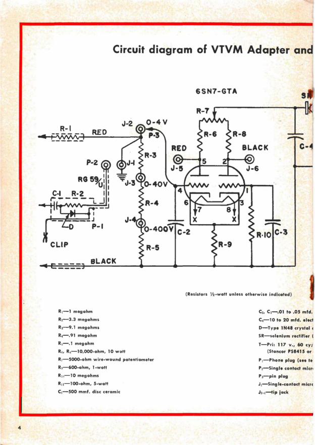
Circuit diagram of VTVM Adapter and
P-2
RO 59/ VI
C -I R-2 I ( r---- J
P -I
CLIP
e==BLACK R-5
R1-1 megahm
R2-3.3 megahms
R3-9.1 megohms
R4-.91 megohm
Rh-.1 megohm
126, RN -10,000 -ohm, 10 watt
R7 -5000 -ohm wire -wound potentiometer
Rai -600 -ohm, 1-wott
Rti, 10 megohms
R11 -100 -ohm, 5 -watt
C1-500 mmf. disc ceramic
4
6SN7-GTA
C-4
(Resistors 1/2 -watt unless otherwise indicated)
C2, C3-.01 to .05 mfd.
C4-10 to 20 mfd. elect
D-Type 1N48 crystal 4
5R-selenium rectifier
T-Pri: 117 v., 60 cy; (Stancor PS8415 or
Pi-Phone plug (see to
Pa-Single contact micr
P3-pin plug
J1-Single-contact mica
Js -,-tip jack

RF probe.
rolytic
liode (see text)
see text)
sec: 125 v. (a} 15 ma. and 6.3 v. G .6 A equivalent)
tt)
'phone cable connector
phone chassis receptacle
jack-this separate connector being provided to accom- modate the coaxial cable and to permit the RF probe to be detached when not in use. If the DC test leads are wired into the circuit, as in the model illustrated, care should be taken not to allow the positive lead to touch a high -voltage spot when the RF probe is in use.
The RF probe is easily constructed with a 4 -foot length of RG-59/U and a phone plug. A plug with solder lugs instead of the machine screw type designed for phone tips was chosen because it provides more room for the resistor, diode and capacitor as well as convenient solder tie points for these components. The construction is clearly shown in the illustration. In this model, the plug tip was removed and the center con- ductor shaft drilled and tapped to receive a machine screw. The screw then was "beheaded" and filed to a point. With some types of plugs it may be possible to merely reshape the tip to serve as the test lead point. The ground clip lead is soldered on the base of the plug as shown in the illustrations.
Practically any selenium rectifier designed to operate in a 120 -volt half -wave rectifier circuit can be used as current drain is very small. A separate power supply can be used, of course, by those who may have a utility supply at hand and wish to avoid the expense of building one to incorporate in this instrument. How- ever, if an external supply is used, care must be taken to make sure the supply voltage is precisely the same every time the meter is used. For variations in the supply voltage may upset the calibration.
USING THE VTVM
A sample of voltage tests made on a grid dip oscilla- tor illustrate the usefulness of a VTVM. The GDO was adjusted so its meter read 1 milliampere. Then the plate voltage was read with first the multi -meter alone, then with an Adapter -multi -meter combination, and finally with a fairly expensive commercially -built VTVM which had been checked against laboratory standards. In each case the effect of the measurement on the GDO current meter was observed.
The multi -meter alone read 46 volts and the GDO current dropped during the test from 1.0 milliampere to .5 milliampere. The Adapter reading was 56 volts and the GDO meter needle dropped only a hair's breadth during the test. The commercially -built VTVM read 55 volts, and again caused only the tiniest flicker on the GDO meter.
The average commercially -built VTVM is granted an error of 5%-which means in the instance cited above that the 55 volts read with the standard VTVM actually could have been anywhere between 52.2 and 57.8 volts (had the meter not been first checked against a laboratory standard). The Adapter reading Came within this range; but the multi -meter reading dropped far below this minimum tolerance. In fact, the 46 -volt reading obtained with the multi -meter alone is an error of more than 16%.
The operating manual for the GDO under test* specifies a plate voltage of 40 to 60 volts. So in this case the use of a multi -meter would not have led an experimenter too far astray. However, it is quite -con- ceivable that a minimum of 50 volts might have been specified. Had this been the case, the multi -meter alone would have indicated insufficient voltage, whereas in fact the voltage was well over the 50 -volt limit.
The uses to which a VTVM can be put are well illustrated in the ARRL "Course in Radio Fundamen- tals" and in many standard electrotlics texts. In addi- tion, the instruction manuals on instruments such as grid dip oscillators often describe how the usefulness of such instruments can be extended when used in con- junction with a VTVM.
Heathkit 5

-"'I7
For instance, the Q of a tuned circuit may be meas- ured by using a GDO and VTVM. Using the RF probe, the VTVM is connected across the tuned circuit. The GDO is loosely coupled to the circuit and output fre- quency adjusted until a maximum reading is obtained on the VTVM. This frequency (f1) can be noted by checking against a calibrated receiver. The GDO fre- quency then should be increased until the VTVM read- ing drops to 70.7% of its original value. Once again the frequency (f:) should be noted by checking against the receiver. Then the GDO frequency should be set below ft at a point where once again the VTVM reads 70.7% of the peak value and this third frequency (fa) noted on the receiver. Then:
f, Q=fs -fa.
The balanced DC amplifier type circuit used in this Adapter is the type most often employed in commer- cially -built VTVM's. The 1-megohm resistor in the positive DC test lead is incorporated in the probe to minimize the capacity effect of the long test lead and thus allows the instrument to be used to make dynamic voltage measurements in circuits carrying oscillator or signal voltages.
Similarly, the crystal diode and associated rectifying components are built into the plug which forms the separate RF probe to provide low capacity to ground.
It is possible with a VTVM to measure AVC voltages in receivers quite accurately-a measurement not possible with conventional voltmeters because their comparatively low internal resistance will shunt out a high resistance AVC circuit. This AVC check, in- cidentally, makes a convenient point for obtaining an output reading when lining up the RF and IF stages of a receiver.
The operation of an oscillator can be checked over its intended frequency range by measuring the value
6
of grid voltage at the oscillator tube socket while tun- ing the circuit over its range.
Since the high impedance of the VTVM allows it to be placed directly on the grid of a tube without seri- ously disturbing the circuit, it is possible to tell whether or not a tube is gassy. A gassy tube will cause a positive voltage to appear across the grid resistor instead of the usual negative voltage. This same condition can exist, however, due to a leaky coupling capacitor-so it is wise not to discard a tube without first also checking the capacitor for leakage.
Because the loading effect of the VTVM is negligible, it is possible to measure current without opening a circuit to insert a milliammeter. The only requirement is the presence of a resistor of known value in the cir- cuit. In this case it is merely necessary to measure the voltage at each end of the resistor, subtract to find the voltage drop, and then apply Ohm's law to determine the current. In designing equipment, it is often quite feasible to insert 100 -ohm resistors at certain points especially for this purpose.
HOW TO GET G -E HAM NEWS
G -E HAM NEWS may be obtained free from G -E tube distributors-or for $1 per year G.E. will mail HAM NEWS to your home. Write to: G -E HAM NEWS, Tube Department, General Electric Co., Schenectady 5, N. Y. This subscription plan is available to amateurs only in the United States, Alaska, Hawaii and the Panama Canal Zone. Amateurs in Canada should address requests to Canadian General Electric Co. Ltd., Electronic Tube Market- ing Section, 830 Lansdowne Ave., Toronto, Ontario, Canada. In all other countries G -E HAM NEWS may be obtained through International General Electric distributors.

ü01J !- SWEEPING 1k SPECTRUM
Another important insulation-which we neglected to mention in our article on the subject last time-is silicone rubber. This material has excellent properties, as well as outstanding resistance to ozone, corona, sun- light and heat.
For those who might wish to add this insulation to the table of statistics given in the May -June, 1954, issue of G -E HAM NEWS (Vol. 9, No. 3), here are the
. ratings: Resistivity (ohm -inches), 10" to 101e; dielectric constant, 3.0 to 3.5; power factor, 0.3 at 60 cy, 0.2 at 1 mc; puncture strength of a 0.080 -inch sample, 400 to 500 volts per mil. Silicone rubber is partly organic and partly inorganic so fits neither of the two general classi- fications in the table accompanying our previous article.
While the electrical properties of silicone rubber are of the same order of magnitude as organic materials at room temperature, they are greatly superior at high temperatures where "pure" organic materials can no longer be used. Silicone rubber is, of course, but one of a large family of materials.
The silicones, incidentally, are something like the schmoo of comic strip fame. We mean nothing deroga- tory in saying that. As you will recall, the schmoos could do anything. And it's much the same with the silicones. In fact, every article we've ever read on the silicones has left us groggy and bewildered. For as the story unfolds, we begin to forget the silicone uses that were recited in the beginning.
Let's put it this way. Silicones are a new class of man- made chemicals, combining the best qualities of sand; coal and oil. Their key material is silicon, which is de- rived from sand-the second most abundant element on earth. As a wartime development, the silicones were under wraps for quite a while after the initial research at the General Electric Research Laboratory in the 1930's;
In its commonest form-a water -white oil-the amazing chemical can be poured in subzero cold and yet survive heat up to 600 degrees F. As a "defoamer," only a drop or two will burst millions of bubbles. As a release agent, silicones keep rubber and plastic objects from sticking in molds. In paint, silicones can shrug off intermittent blasts of heat up to 1200 degrees F for 72 consecutive hours.
The various silicones are combinations of oxygen and one or more hydrocarbon with silicon. By varying the proportions and types of hydrocarbons, the chemist can produce silicones ranging in stability and flexibility from volatile liquids to stable solids. They are used as spreading agents in waxes and polishes, as water -re- pellents on insulation and textiles, as grease insulation on spark -plug terminals, and in many places where a non -corrosive seal is needed.
Scientists see in the future silicones replacing damaged vital parts of human tissue, silicone tires that will last the life of the car, silicone bunion pads and hygienic baby pants, stain- and spot -resistant clothes and-well, it does get bewildering. Think we'll try spraying a drop or two into the atmosphere to see if it will dispel the QRM.
11 11
A dozen 10 -meter mobiles from these parts went out .to a nearby reservoir one recent week end and provided communications for a "carp -shooting contest." The shooting was done by bow and arrow and scoring kept up-to-the-minute by five mobile stations repórting in to a HQ station. Ham radio came in for quite a bit of praise and a trophy was awarded the hams for their work. The boys' big question now is what are they going to do with the trophy? Who's going to keep it? They don't all belong to one club. They can pass it around for a while. Then what? Any suggestions?
11 11 11
To succeed in amateur operating a fellow has to de- velop a fairly high degree of patience, as old timers know very well. A recent example of this was brought to our attention when a ham we know attempted to contact a friend of a visitor in his shack. No sked had been ar- ranged but the ham knew the other fellow often was on the air near a certain frequency around 8 o'clock at night. While the visitor sat and waited without much hope of making the contact, our friend alternately combed the specified frequencies, called a few times and alerted several other hams working nearby. Pretty soon they heard someone testing-and there was the contact. The visitor was much impressed-but our friend thought nothing of it.
Another example of ham patience is reported in a recent issue of the Rochester (N. Y.) Amateur Radio Association Rag. W2SAW followed the Clipperton Island expedition for days and then started to call them at 6:30 one morning. He called constantly until the following morning at 2:45 when he made the contact.
1-1 11 11
Our editor thinks he may have received one of the last QSL cards from Nicaragua-at least for a time. He got a card from a YN1-who he worked on 75 -meter SSB with a l0A and 6146-together with a letter which said the YN1's were off the air due to "some internal difficulty." A week or so later the news broke about arms shipments from Czechoslovakia to neighboring Guatemala-which our editor thinks probably had something to do with the "internal difficulty." - .2Q/tltff

Technical Information
SLICING UP ELECTRONIC TUBES
What spacing exists between the components of a tube after it is put together? Breaking sample tubes open and and looking at them is unsatisfactory because the' disassembly process could disturb the placement of the elements.
G.E. solves this inspection problem by filling samples from the production line with plastic-and then slicing the tubes cross -wise and/or length -wise to check the spacing of elements.
In some cases, the tube is immersed in a clear liquid plastic, and the glass tip broken off. Because of the vacuum inside the tube, normal atmospheric pressure forces the liquid plastic into the tube. In other instances, a hole is drilled in the tube (see hole in cap of the 2C39 -A illustrated) and tube evacuated again in a special vessel which also contains the plastic liquid.
Chemical action and baking harden the plastic in a few hours with the elements undisturbed. Then the glass envelope can be cracked away, and the plastic - encased elements sliced into sections and polished for study under a microscope.
Careful inspection of the illustration will reveal the filament, grid and even the solder in one pin-just as they actually ended up in a finished tube.
f
t
TUBES
1i -E HAM NEWS
G -E Electronic Tube Distributors
VOL. 9 - NO. 4 JULY - AUGUST, 1954
published bi-monthly by TUBE DEPARTMENT
GENERAL C/ ELECTRIC Schenectady 5, N. Y.
In Canada Canadian General Electric Ca.,"Ltd.
Toronto, Ontario
S. E. McCALLUM, W2ZBY-EDITOR
i