flowconflowconme.com/wp-content/uploads/2017/12/fittings.pdf · astm a815, uns31803, uns32750,...
TRANSCRIPT

flowconME
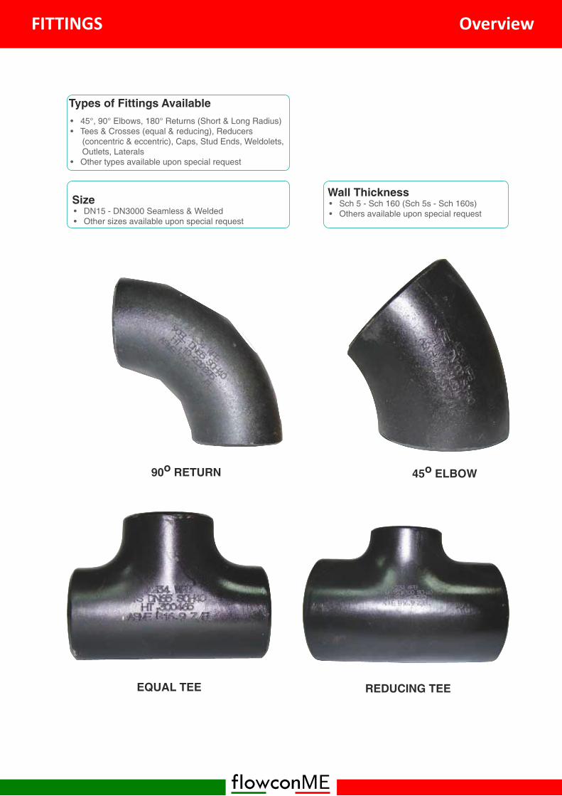
Types of Fittings Available• 45°, 90° Elbows, 180° Returns (Short & Long Radius)• Tees & Crosses (equal & reducing), Reducers
(concentric & eccentric), Caps, Stud Ends, Weldolets,Outlets, Laterals
• Other types available upon special request
90o RETURN
EQUAL TEE
45o ELBOW
REDUCING TEE
Size• DN15 - DN3000 Seamless & Welded• Other sizes available upon special request
Wall Thickness• Sch 5 - Sch 160 (Sch 5s - Sch 160s)• Others available upon special request
FITTINGS Overview

flowconME
ASME B16.9MSS SP-43MSS SP-75DIN 2605, 2615, 2616, 2617More Standards available upon special request
Manufacturing Standards
Available Material & Specifications
Description Material
Stainless SteelAmerican: 304 / 304L, 316 / 316L, 321 / 321H, 317L, 904L
DIN: 1.4541, 1.4571, 1.4301, 1.4406
Duplex &
Super SSASTM A815, UNS31803, UNS32750, UNS32760
Carbon SteelA234, WPB, WPC
ASTM A420, WPL3/L6/L9, ASTM 860 WPHY 42/46/52/56/60/65/70
Alloy Steel A234 WP1, WP5, WP9, WP11, WP22, WP91
Others Copper - Nickle Alloy, Titanium, Aluminium, Monel, Incone, Hastelloy & other special
material
More available upon special request
CONCENTRIC REDUCER ECCENTRIC REDUCER
FITTINGS Overview
flowconME
NominalPipe Size
45°Elbow 90° Elbow 180° Return
H F P K
DN NPS LongRadius
LongRadius
ShortRadius
LongRadius
ShortRadius
LongRadius
ShortRadius
15 16 38 - 76 - 48 -
20 16 38 - 76 - 51 -
25 1 16 38 25 76 51 56 41
32 1¼ 20 48 32 95 64 70 52
40 1½ 24 57 38 114 76 83 62
50 2 32 76 57 152 102 106 81
65 2½ 40 95 64 191 127 132 100
80 3 47 114 76 229 152 159 121
90 3½ 55 133 89 267 178 184 140
100 4 63 152 102 305 203 210 159
125 5 79 190 127 381 254 262 197
150 6 95 229 152 457 305 313 237
200 8 126 305 203 610 406 414 313
250 10 158 381 254 762 508 518 391
300 12 189 457 305 914 610 619 467
350 14 221 533 356 1067 711 711 533
400 16 253 610 406 1219 813 813 610
450 18 284 686 457 1372 914 914 686
500 20 316 762 508 1524 1016 1016 762
550 22 347 838 559 1676 1118 1118 838
600 24 379 914 610 1829 1219 1219 914
650 26 410 991 660
700 28 442 1067 771
750 30 473 1143 462
800 32 505 1219 813
850 34 537 1295 864
900 36 568 1372 914
950 38 600 1448 965
1000 40 631 1524 1016
1050 42 663 1600 1067
1100 44 694 1676 1118
1150 46 729 1753 1168
1200 48 758 1829 1219
1300 52 821 1981 1321
1400 56 883 2134 1420
1500 60 947 2286 1524
1600 64 1010 2438 1620
1700 68 1073 2591 1727
1800 72 1137 2743 1829
1900 76 1199 2896 1930
2000 80 1263 3048 2032All dimensions are nominal (indicative).Actual dimensions may vary.
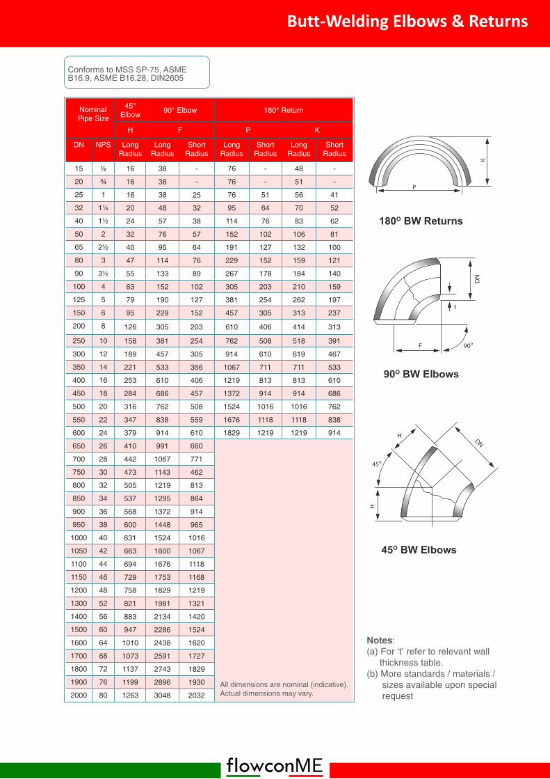
Notes:(a) For ‘t’ refer to relevant wall
thickness table.(b) More standards / materials /
sizes available upon specialrequest
Conforms to MSS SP-75, ASMEB16.9, ASME B16.28, DIN2605
Butt-Welding Elbows & Returns

flowconME
NominalPipe Size
OutsideDiameter
Wall Thickness for 90° LR Elbows Wall Thickness for 90° SR Elbows
sch20 STD sch40 XS sch80 sch20 STD sch40 XS sch80
mm mm mm mm mm mm mm mm mm mm
21.3 2.77 2.77 3.73 3.73
26.7 2.87 2.87 3.91 3.91
1 33.4 3.38 3.38 4.55 4.55 3.38 3.38 4.55 4.55
1¼ 42.2 3.56 3.56 4.85 4.85 3.56 3.56 4.85 4.85
1½ 48.3 3.68 3.68 5.08 5.08 3.68 3.68 5.08 5.08
2 60.3 3.91 3.91 5.54 5.54 3.91 3.91 5.54 5.54
2½ 73 5.16 5.16 7.01 7.01 5.16 5.16 7.01 7.01
3 88.9 5.49 5.49 7.62 7.62 5.49 5.49 7.62 7.62
3½ 101.6 5.74 5.74 8.08 8.08 5.74 5.74 8.08 8.08
4 114.3 6.02 6.02 8.56 8.56 6.02 6.02 8.56 8.56
5 141.3 6.55 6.55 9.53 9.53 6.55 6.55 9.53 9.53
6 168.3 7.11 7.11 10.97 10.97 7.11 7.11 10.97 10.97
8 219.1 6.35 8.18 8.18 12.7 12.7 6.35 8.18 8.18 12.7 12.7
10 273.1 6.35 9.27 9.27 12.7 15.09 6.35 9.27 9.27 12.7 15.09
12 323.9 6.35 9.53 10.31 12.7 17.48 6.35 9.53 10.31 12.7 17.48
14 355.6 7.92 9.53 11.31 12.7 19.05 7.92 9.53 11.31 12.7 19.05
16 406.4 7.92 9.53 12.7 12.7 21.44 7.92 9.53 12.7 12.7 21.44
18 457.2 7.92 9.53 14.27 12.7 23.83 7.92 9.53 14.27 12.7 23.83
20 508 9.53 9.53 15.09 12.7 26.19 9.53 9.53 15.09 12.7 26.19
22 558.8 9.53 9.53 12.7 28.58 9.53 9.53 12.7 28.58
24 609.6 9.53 9.53 17.48 12.7 30.96 9.53 9.53 17.48 12.7 30.96
26 660.4 12.7 9.53 12.7 9.53 12.7
28 711.2 12.7 9.53 12.7 9.53 12.7
30 762 12.7 9.53 12.7 9.53 12.7
32 812.8 12.7 9.53 17.48 12.7 9.53 17.48 12.7
34 863.6 12.7 9.53 17.48 12.7 9.53 17.48 12.7
36 914.4 12.7 9.53 19.05 12.7 9.53 19.05 12.7
38 965.2 9.53 12.7 9.53 12.7
40 1016 9.53 12.7 9.53 12.7
42 1066.8 9.53 12.7 9.53 12.7
44 1117.6 9.53 12.7 9.53 12.7
46 1168.4 9.53 12.7 9.53 12.7
48 1219.2 9.53 12.7 9.53 12.7
All dimensions are nominal (indicative).Actual dimensions may vary.
Note:More standards / materials / sizesavailable upon special request
Wall Thickness for Carbon Steel90° Elbows (SR & LR)

flowconME
Nominal Pipe Size Center to End
DN,DN1 x DN2 NPS
C M
mm mm
15 25 25
2029
29
20x15 ¾x½ 29
25 1
38
38
25x20 1x¾ 38
25x15 1x½ 38
32 1¼
48
48
32x25 1¼x1 48
32x20 1¼x¾ 48
32x15 1¼x½ 48
40 1½
57
57
40x32 1½x1¼ 57
40x25 1½x1 57
40x20 1½x¾ 57
40x15 1½x½ 57
50 2
64
64
50x40 2x1½ 60
50x32 2x1¼ 57
50x25 2x1 51
50x20 2x¾ 44
65 2½
76
76
65x50 2½x2 70
65x40 2½x1½ 67
65x32 2½x1¼ 64
65x25 2½x1 57
80 3
86
86
80x65 3x2½ 83
80x50 3x2 76
80x40 3x1½ 73
80x32 3x1¼ 70
90 3½
95
95
90x80 3½x3 92
90x65 3½x2½ 89
90x50 3½x2 83
90x40 3½x1½ 79
100 4
105
105
100x80 4x3 98
100x65 4x2½ 95
100x50 4x2 89
100x40 4x1½ 86
All dimensions are nominal (indicative).Actual dimensions may vary.
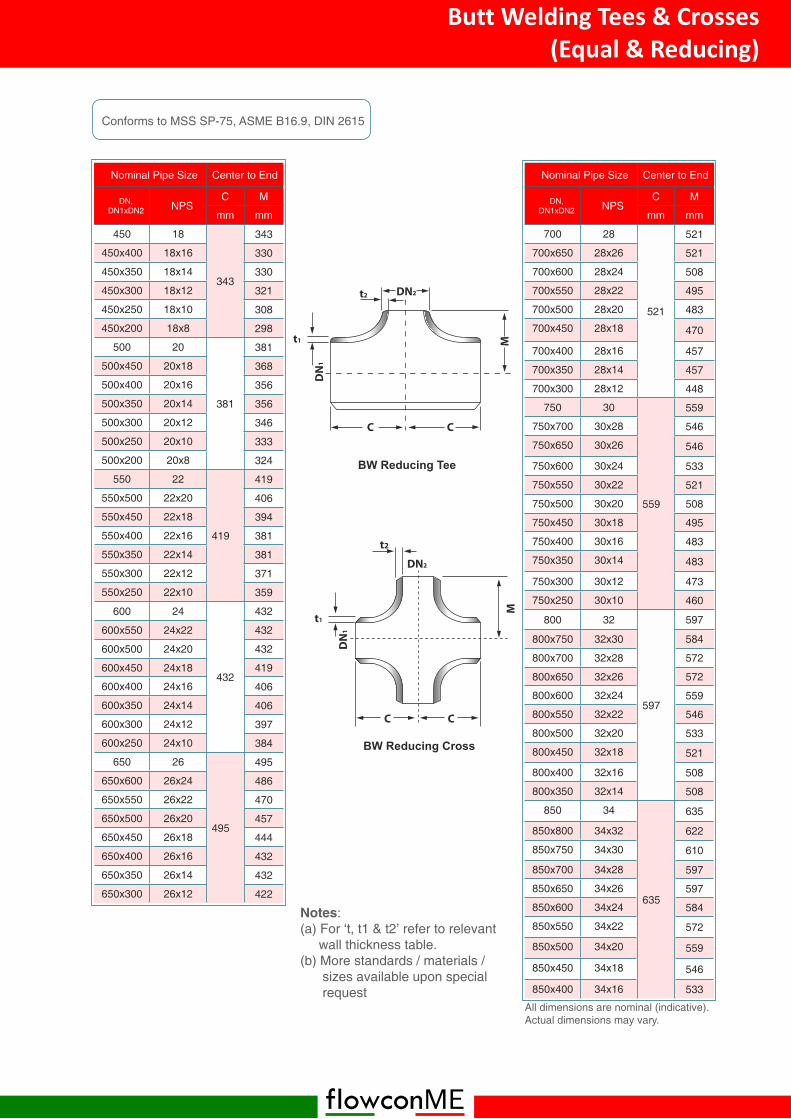
Conforms to MSS SP-75, ASME B16.9, DIN 2615
Nominal Pipe Size Center to End
DN,DN1 x DN2 NPS
C M
mm mm
125 5
124
124
125x100 5x4 117
125x90 5x3½ 114
125x80 5x3 111
125x65 5x2½ 108
125x50 5x2 105
150 6
143
143
150x125 6x5 137
150x100 6x4 130
150x90 6x3½ 127
150x80 6x3 124
150x65 6x2½ 121
200 8
178
178
200x150 8x6 168
200x125 8x5 162
200x100 8x4 156
200x90 8x3½ 152
200x80 8x3 152
250 10
216
216
250x200 10x8 203
250x150 10x6 194
250x125 10x5 191
250x100 10x4 184
300 12
254
254
300x250 12x10 241
300x200 12x8 229
300x150 12x6 219
300x125 12x5 216
350 14
279
279
350x300 14x12 270
350x250 14x10 257
350x200 14x8 248
350x150 14x6 238
400 16
305
305
400x350 16x14 305
400x300 16x12 295
400x250 16x10 283
400x200 16x8 273
400x150 16x6 264
Notes:(a) For ‘t, t1 & t2’ refer to relevant
wall thickness table.(b) More standards / materials /
sizes available upon specialrequest
Butt Welding Tees & Crosses(Equal & Reducing)
flowconME
Nominal Pipe Size Center to End
DN,DN1xDN2 NPS
C M
mm mm
450 18
343
343
450x400 18x16 330
450x350 18x14 330
450x300 18x12 321
450x250 18x10 308
450x200 18x8 298
500 20
381
381
500x450 20x18 368
500x400 20x16 356
500x350 20x14 356
500x300 20x12 346
500x250 20x10 333
500x200 20x8 324
550 22
419
419
550x500 22x20 406
550x450 22x18 394
550x400 22x16 381
550x350 22x14 381
550x300 22x12 371
550x250 22x10 359
600 24
432
432
600x550 24x22 432
600x500 24x20 432
600x450 24x18 419
600x400 24x16 406
600x350 24x14 406
600x300 24x12 397
600x250 24x10 384
650 26
495
495
650x600 26x24 486
650x550 26x22 470
650x500 26x20 457
650x450 26x18 444
650x400 26x16 432
650x350 26x14 432
650x300 26x12 422
All dimensions are nominal (indicative).Actual dimensions may vary.
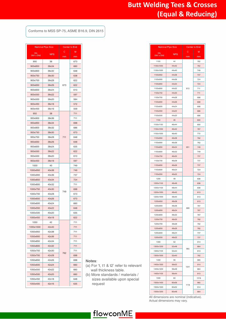
Conforms to MSS SP-75, ASME B16.9, DIN 2615
Nominal Pipe Size Center to End
DN,DN1xDN2 NPS
C M
mm mm
700 28
521
521
700x650 28x26 521
700x600 28x24 508
700x550 28x22 495
700x500 28x20 483
700x450 28x18 470
700x400 28x16 457
700x350 28x14 457
700x300 28x12 448
750 30
559
559
750x700 30x28 546
750x650 30x26 546
750x600 30x24 533
750x550 30x22 521
750x500 30x20 508
750x450 30x18 495
750x400 30x16 483
750x350 30x14 483
750x300 30x12 473
750x250 30x10 460
800 32
597
597
800x750 32x30 584
800x700 32x28 572
800x650 32x26 572
800x600 32x24 559
800x550 32x22 546
800x500 32x20 533
800x450 32x18 521
800x400 32x16 508
800x350 32x14 508
850 34
635
635
850x800 34x32 622
850x750 34x30 610
850x700 34x28 597
850x650 34x26 597
850x600 34x24 584
850x550 34x22 572
850x500 34x20 559
850x450 34x18 546
850x400 34x16 533
Notes:(a) For ‘t, t1 & t2’ refer to relevant
wall thickness table.(b) More standards / materials /
sizes available upon specialrequest
Butt Welding Tees & Crosses(Equal & Reducing)
flowconME
Nominal Pipe Size Center to End
DN,DN1 x DN2 NPS
C M
mm mm
900 36
673
673
900x850 36x34 660
900x800 36x32 648
900x750 36x30 638
900x700 36x28 622
900x650 36x26 622
900x600 36x24 610
900x550 36x22 597
900x500 36x20 584
900x450 36x18 572
900x400 36x16 559
950 38
711
711
950x900 38x36 711
950x850 38x34 698
950x800 38x32 686
950x750 38x30 673
950x700 38x28 648
950x650 38x26 648
950x600 38x24 635
950x550 38x22 622
950x500 38x20 610
950x450 38x18 597
1000 40
749
749
1000x950 40x38 749
1000x900 40x36 737
1000x850 40x34 724
1000x800 40x32 711
1000x750 40x30 698
1000x700 40x28 673
1000x650 40x26 673
1000x600 40x24 660
1000x550 40x22 648
1000x500 40x20 635
1000x450 40x18 622
1050 42
762
711
1050x1000 42x40 711
1050x950 42x38 711
1050x900 42x36 711
1050x850 42x34 711
1050x800 42x32 711
1050x750 42x30 711
1050x700 42x28 698
1050x650 42x26 698
1050x600 42x24 660
1050x550 42x22 660
1050x500 42x20 660
1050x450 42x18 648
1050x400 42x16 635
All dimensions are nominal (indicative).Actual dimensions may vary.
Conforms to MSS SP-75, ASME B16.9, DIN 2615
Nominal Pipe Size Center to End
DN,DN1 x DN2 NPS
C M
mm mm
1100 44
813
762
1100x1050 44x42 762
1100x1000 44x40 749
1100x950 44x38 737
1100x900 44x36 724
1100x850 44x34 724
1100x800 44x32 711
1100x750 44x30 711
1100x700 44x28 698
1100x650 44x26 698
1100x600 44x24 698
1100x550 44x22 686
1100x500 44x20 686
1150 46
851
800
1150x1100 46x44 800
1150x1050 46x42 787
1150x1000 46x40 772
1150x950 46x38 762
1150x900 46x36 762
1150x850 46x34 749
1150x800 46x32 749
1150x750 46x30 737
1150x700 46x28 737
1150x650 46x26 737
1150x600 46x24 724
1150x550 46x22 724
1200 48
889
838
1200x1150 48x46 838
1200x1100 48x44 838
1200x1050 48x42 813
1200x1000 48x40 813
1200x950 48x38 813
1200x900 48x36 787
1200x850 48x34 787
1200x800 48x32 787
1200x750 48x30 762
1200x700 48x28 762
1200x650 48x26 762
1200x600 48x24 737
1200x550 48x22 737
1300 52
965
914
1300x1200 52x48 864
1300x1100 52x44 813
1300x1000 52x40 762
1400 56
1041
965
1400x1300 56x52 914
1400x1200 56x48 864
1400x1100 56x44 813
1500 60
1118
1016
1500x1400 60x56 965
1500x1300 60x52 914
1500x1200 60x48 864
Notes:(a) For ‘t, t1 & t2’ refer to relevant
wall thickness table.(b) More standards / materials /
sizes available upon specialrequest
Butt Welding Tees & Crosses(Equal & Reducing)
flowconME
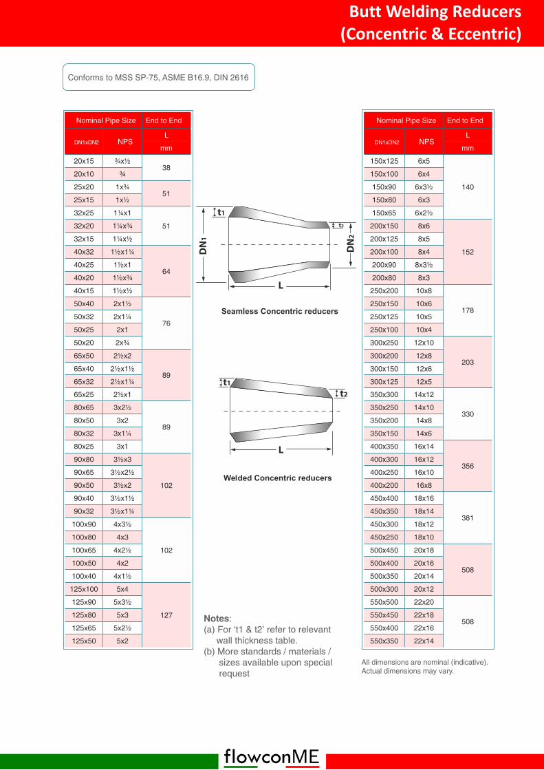
Nominal Pipe Size End to End
DN1xDN2 NPSL
mm
20x15 ¾x½38
20x10
25x20 1x¾51
25x15 1x½
32x25 1¼x1
5132x20 1¼x¾
32x15 1¼x½
40x32 1½x1¼
6440x25 1½x1
40x20 1½x¾
40x15 1½x½
50x40 2x1½
7650x32 2x1¼
50x25 2x1
50x20 2x¾
65x50 2½x2
8965x40 2½x1½
65x32 2½x1¼
65x25 2½x1
80x65 3x2½
8980x50 3x2
80x32 3x1¼
80x25 3x1
90x80 3½x3
102
90x65 3½x2½
90x50 3½x2
90x40 3½x1½
90x32 3½x1¼
100x90 4x3½
102
100x80 4x3
100x65 4x2½
100x50 4x2
100x40 4x1½
125x100 5x4
127
125x90 5x3½
125x80 5x3
125x65 5x2½
125x50 5x2
All dimensions are nominal (indicative).Actual dimensions may vary.
Conforms to MSS SP-75, ASME B16.9, DIN 2616
Nominal Pipe Size End to End
DN1xDN2 NPSL
mm
150x125 6x5
140
150x100 6x4
150x90 6x3½
150x80 6x3
150x65 6x2½
200x150 8x6
152
200x125 8x5
200x100 8x4
200x90 8x3½
200x80 8x3
250x200 10x8
178250x150 10x6
250x125 10x5
250x100 10x4
300x250 12x10
203300x200 12x8
300x150 12x6
300x125 12x5
350x300 14x12
330350x250 14x10
350x200 14x8
350x150 14x6
400x350 16x14
356400x300 16x12
400x250 16x10
400x200 16x8
450x400 18x16
381450x350 18x14
450x300 18x12
450x250 18x10
500x450 20x18
508500x400 20x16
500x350 20x14
500x300 20x12
550x500 22x20
508550x450 22x18
550x400 22x16
550x350 22x14
Notes:(a) For ‘t1 & t2’ refer to relevant
wall thickness table.(b) More standards / materials /
sizes available upon specialrequest
Butt Welding Reducers(Concentric & Eccentric)

flowconME
Nominal Pipe Size End to End
DN1xDN2 NPSL
mm
600x550 24x22
508600x500 24x20
600x450 24x18
600x400 24x16
650x600 26x24
610650x550 26x22
650x500 26x20
650x450 26x18
700x650 28x26
610
700x600 28x24
700x550 28x22
700x500 28x20
700x450 28x18
750x700 30x28
610
750x650 30x26
750x600 30x24
750x550 30x22
750x500 30x20
800x750 32x30
610800x700 32x28
800x650 32x26
800x600 32x24
850x800 34x32
610
850x750 34x30
850x700 34x28
850x650 34x26
850x600 34x24
900x850 36x34
610
900x800 36x32
900x750 36x30
900x700 36x28
900x650 36x26
900x600 36x24
950x900 38x36
610
950x850 38x34
950x800 38x32
950x750 38x30
950x700 38x28
950x650 38x26All dimensions are nominal (indicative).Actual dimensions may vary.
Conforms to MSS SP-75, ASME B16.9, DIN 2616
Nominal Pipe Size End to End
DN1xDN2 NPSL
mm
1000x950 40x38
610
1000x900 40x36
1000x850 40x34
1000x800 40x32
1000x750 40x30
1000x700 40x28
1050x1000 42x40
610
1050x950 42x38
1050x900 42x36
1050x850 42x34
1050x800 42x32
1050x750 42x30
1100x1050 44x42
610
1100x1000 44x40
1100x950 44x38
1100x900 44x36
1100x850 44x34
1100x800 44x32
1150x1100 46x44
7111150x1050 46x42
1150x1000 46x40
1150x950 46x38
1200x1150 48x46
711
1200x1100 48x44
1200x1050 48x42
1200x1000 48x40
1200x950 48x38
1200x900 48x36
1300x1200 52x48
7111300x1100 52x44
1300x1000 52x40
1400x1300 56x52
7111400x1200 56x48
1400x1100 56x44
1500x1400 60x56
7111500x1300 60x52
1500x1200 60x48
Notes:(a) For ‘t1 & t2’ refer to relevant
wall thickness table.(b) More standards / materials /
sizes available upon specialrequest
Butt Welding Reducers(Concentric & Eccentric)
flowconME
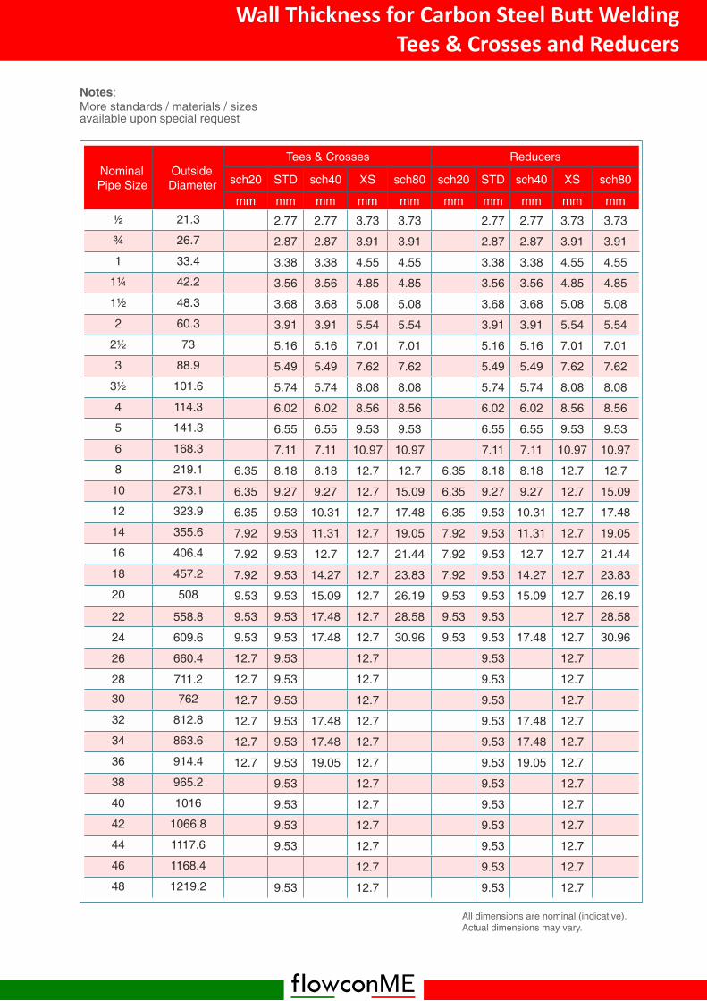
NominalPipe Size
OutsideDiameter
Tees & Crosses Reducers
sch20 STD sch40 XS sch80 sch20 STD sch40 XS sch80
mm mm mm mm mm mm mm mm mm mm
21.3 2.77 2.77 3.73 3.73 2.77 2.77 3.73 3.73
26.7 2.87 2.87 3.91 3.91 2.87 2.87 3.91 3.91
1 33.4 3.38 3.38 4.55 4.55 3.38 3.38 4.55 4.55
1¼ 42.2 3.56 3.56 4.85 4.85 3.56 3.56 4.85 4.85
1½ 48.3 3.68 3.68 5.08 5.08 3.68 3.68 5.08 5.08
2 60.3 3.91 3.91 5.54 5.54 3.91 3.91 5.54 5.54
2½ 73 5.16 5.16 7.01 7.01 5.16 5.16 7.01 7.01
3 88.9 5.49 5.49 7.62 7.62 5.49 5.49 7.62 7.62
3½ 101.6 5.74 5.74 8.08 8.08 5.74 5.74 8.08 8.08
4 114.3 6.02 6.02 8.56 8.56 6.02 6.02 8.56 8.56
5 141.3 6.55 6.55 9.53 9.53 6.55 6.55 9.53 9.53
6 168.3 7.11 7.11 10.97 10.97 7.11 7.11 10.97 10.97
8 219.1 6.35 8.18 8.18 12.7 12.7 6.35 8.18 8.18 12.7 12.7
10 273.1 6.35 9.27 9.27 12.7 15.09 6.35 9.27 9.27 12.7 15.09
12 323.9 6.35 9.53 10.31 12.7 17.48 6.35 9.53 10.31 12.7 17.48
14 355.6 7.92 9.53 11.31 12.7 19.05 7.92 9.53 11.31 12.7 19.05
16 406.4 7.92 9.53 12.7 12.7 21.44 7.92 9.53 12.7 12.7 21.44
18 457.2 7.92 9.53 14.27 12.7 23.83 7.92 9.53 14.27 12.7 23.83
20 508 9.53 9.53 15.09 12.7 26.19 9.53 9.53 15.09 12.7 26.19
22 558.8 9.53 9.53 17.48 12.7 28.58 9.53 9.53 12.7 28.58
24 609.6 9.53 9.53 17.48 12.7 30.96 9.53 9.53 17.48 12.7 30.96
26 660.4 12.7 9.53 12.7 9.53 12.7
28 711.2 12.7 9.53 12.7 9.53 12.7
30 762 12.7 9.53 12.7 9.53 12.7
32 812.8 12.7 9.53 17.48 12.7 9.53 17.48 12.7
34 863.6 12.7 9.53 17.48 12.7 9.53 17.48 12.7
36 914.4 12.7 9.53 19.05 12.7 9.53 19.05 12.7
38 965.2 9.53 12.7 9.53 12.7
40 1016 9.53 12.7 9.53 12.7
42 1066.8 9.53 12.7 9.53 12.7
44 1117.6 9.53 12.7 9.53 12.7
46 1168.4 12.7 9.53 12.7
48 1219.2 9.53 12.7 9.53 12.7
All dimensions are nominal (indicative).Actual dimensions may vary.
Notes:More standards / materials / sizesavailable upon special request
Wall Thickness for Carbon Steel Butt WeldingTees & Crosses and Reducers
flowconME
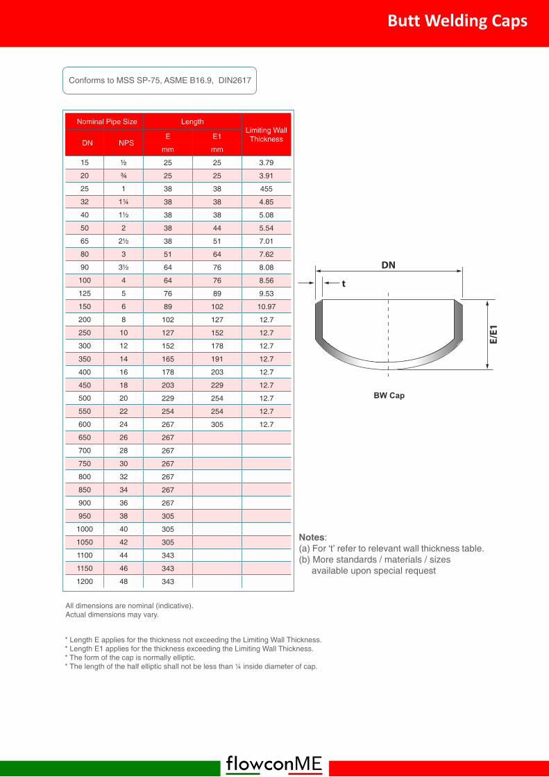
Nominal Pipe Size LengthLimiting Wall
ThicknessDN NPSE E1
mm mm
15 25 25 3.79
20 25 25 3.91
25 1 38 38 455
32 1¼ 38 38 4.85
40 1½ 38 38 5.08
50 2 38 44 5.54
65 2½ 38 51 7.01
80 3 51 64 7.62
90 3½ 64 76 8.08
100 4 64 76 8.56
125 5 76 89 9.53
150 6 89 102 10.97
200 8 102 127 12.7
250 10 127 152 12.7
300 12 152 178 12.7
350 14 165 191 12.7
400 16 178 203 12.7
450 18 203 229 12.7
500 20 229 254 12.7
550 22 254 254 12.7
600 24 267 305 12.7
650 26 267
700 28 267
750 30 267
800 32 267
850 34 267
900 36 267
950 38 305
1000 40 305
1050 42 305
1100 44 343
1150 46 343
1200 48 343
All dimensions are nominal (indicative).Actual dimensions may vary.
Conforms to MSS SP-75, ASME B16.9, DIN2617
* Length E applies for the thickness not exceeding the Limiting Wall Thickness.* Length E1 applies for the thickness exceeding the Limiting Wall Thickness.* The form of the cap is normally elliptic.* The length of the half elliptic shall not be less than ¼ inside diameter of cap.
Notes:(a) For ‘t’ refer to relevant wall thickness table.(b) More standards / materials / sizes
available upon special request
Butt Welding Caps
flowconME
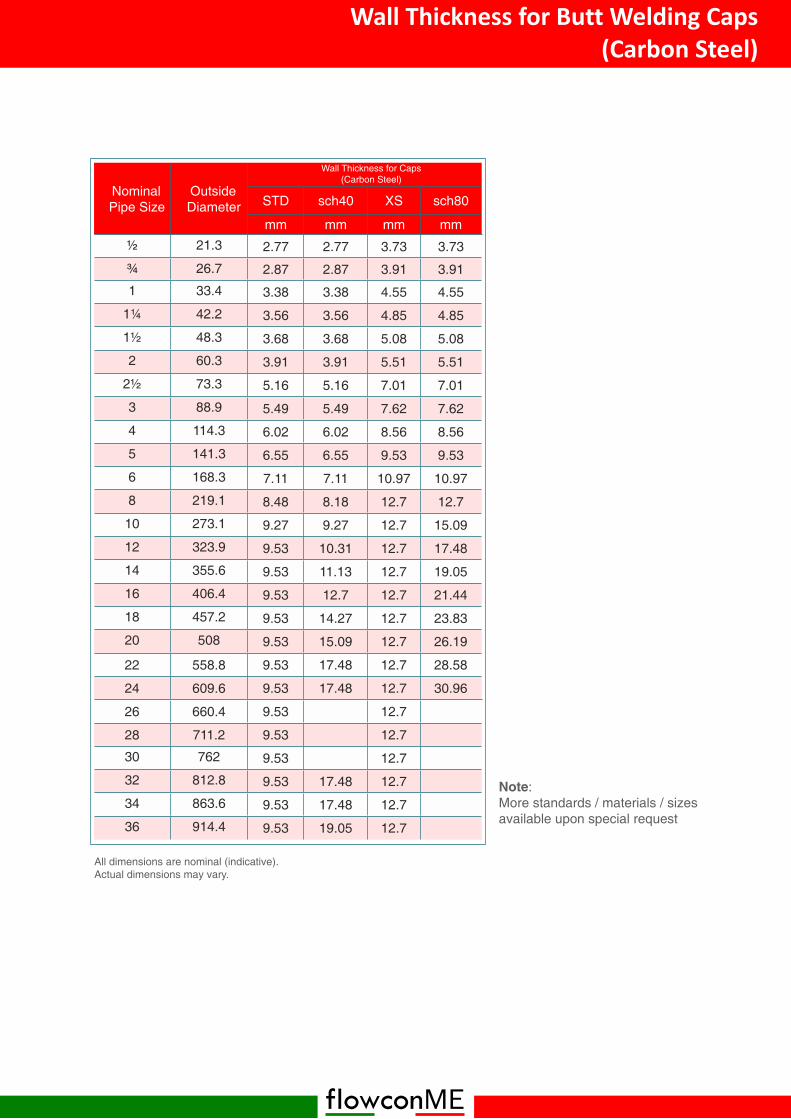
NominalPipe Size
OutsideDiameter STD sch40 XS sch80
mm mm mm mm
21.3 2.77 2.77 3.73 3.73
26.7 2.87 2.87 3.91 3.91
1 33.4 3.38 3.38 4.55 4.55
1¼ 42.2 3.56 3.56 4.85 4.85
1½ 48.3 3.68 3.68 5.08 5.08
2 60.3 3.91 3.91 5.51 5.51
2½ 73.3 5.16 5.16 7.01 7.01
3 88.9 5.49 5.49 7.62 7.62
4 114.3 6.02 6.02 8.56 8.56
5 141.3 6.55 6.55 9.53 9.53
6 168.3 7.11 7.11 10.97 10.97
8 219.1 8.48 8.18 12.7 12.7
10 273.1 9.27 9.27 12.7 15.09
12 323.9 9.53 10.31 12.7 17.48
14 355.6 9.53 11.13 12.7 19.05
16 406.4 9.53 12.7 12.7 21.44
18 457.2 9.53 14.27 12.7 23.83
20 508 9.53 15.09 12.7 26.19
22 558.8 9.53 17.48 12.7 28.58
24 609.6 9.53 17.48 12.7 30.96
26 660.4 9.53 12.7
28 711.2 9.53 12.7
30 762 9.53 12.7
32 812.8 9.53 17.48 12.7
34 863.6 9.53 17.48 12.7
36 914.4 9.53 19.05 12.7
All dimensions are nominal (indicative).Actual dimensions may vary.
Note:More standards / materials / sizesavailable upon special request
Wall Thickness for Caps(Carbon Steel)
Wall Thickness for Butt Welding Caps(Carbon Steel)
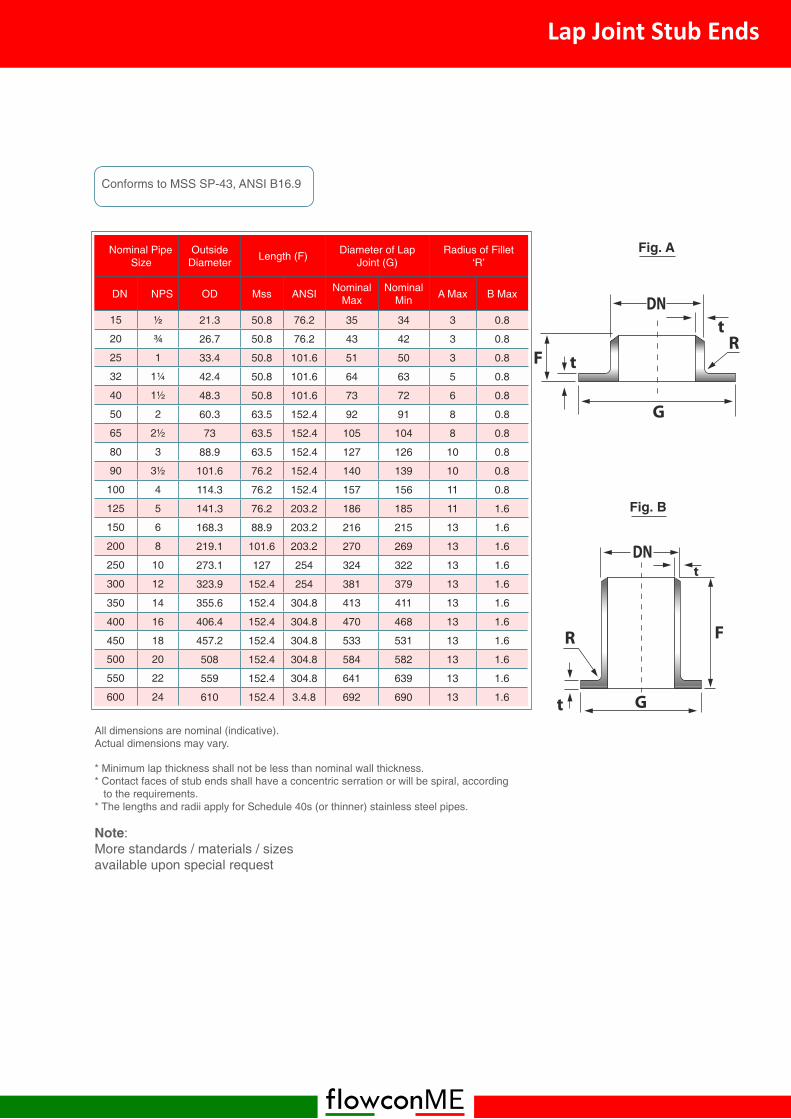
flowconME
Nominal PipeSize
OutsideDiameter Length (F) Diameter of Lap
Joint (G)Radius of Fillet
‘R’
DN NPS OD Mss ANSI NominalMax
NominalMin A Max B Max
15 21.3 50.8 76.2 35 34 3 0.8
20 26.7 50.8 76.2 43 42 3 0.8
25 1 33.4 50.8 101.6 51 50 3 0.8
32 1¼ 42.4 50.8 101.6 64 63 5 0.8
40 1½ 48.3 50.8 101.6 73 72 6 0.8
50 2 60.3 63.5 152.4 92 91 8 0.8
65 2½ 73 63.5 152.4 105 104 8 0.8
80 3 88.9 63.5 152.4 127 126 10 0.8
90 3½ 101.6 76.2 152.4 140 139 10 0.8
100 4 114.3 76.2 152.4 157 156 11 0.8
125 5 141.3 76.2 203.2 186 185 11 1.6
150 6 168.3 88.9 203.2 216 215 13 1.6
200 8 219.1 101.6 203.2 270 269 13 1.6
250 10 273.1 127 254 324 322 13 1.6
300 12 323.9 152.4 254 381 379 13 1.6
350 14 355.6 152.4 304.8 413 411 13 1.6
400 16 406.4 152.4 304.8 470 468 13 1.6
450 18 457.2 152.4 304.8 533 531 13 1.6
500 20 508 152.4 304.8 584 582 13 1.6
550 22 559 152.4 304.8 641 639 13 1.6
600 24 610 152.4 3.4.8 692 690 13 1.6
All dimensions are nominal (indicative).Actual dimensions may vary.
Conforms to MSS SP-43, ANSI B16.9
* Minimum lap thickness shall not be less than nominal wall thickness.* Contact faces of stub ends shall have a concentric serration or will be spiral, according
to the requirements.* The lengths and radii apply for Schedule 40s (or thinner) stainless steel pipes.
Note:More standards / materials / sizesavailable upon special request
Fig. A
Fig. B
Lap Joint Stub Ends

flowconME
NominalDiameter
Nominal Diameterof Suited Main
PipeL E
DN NPS mm in STD XS XXS STD XS XXS
6 1/8 20 15.9 15.9
8 20 15.9 15.9
10 3/8 25 1 19.1 19.1
15 32 1¼ 19.1 19.1 28.6 23.8 23.8 14.3
20 40 1½ 22.2 22.2 31.8 30.2 30.2 19.1
25 1 40 1½ 27 27 38.1 36.5 36.5 25.4
32 1¼ 65 2½ 31.8 31.8 44.5 44.5 44.5 33.3
40 1½ 65 2½ 33.3 33.3 50.8 50.8 50.8 38.1
50 2 80 3 38.1 38.1 58.6 65.1 65.1 42.9
65 2½ 100 4 41.3 41.3 61.9 76.2 76.2 54
80 3 125 5 44.3 44.3 73 93.7 93.7 73
90 3½ 150 6 47 47 101.6 101.6
100 4 150 6 50.8 50.8 84.1 120.7 120.7 98.4
125 5 200 8 57.2 57.2 93.7 141.3 141.3 122.2
150 6 200 8 60.3 77.8 104.8 169.9 169.9 146.1
200 8 250 10 69.9 98.4 220.7 220.7
250 10 300 12 77.8 93.7 274.6 265.1
300 12 350 14 85.7 103.2 325.4 317.5
350 14 400 16 88.9 100 357.2 350.9
400 16 450 18 93.7 106.4 408 403.2
450 18 500 20 96.8 111.1 458.8 455.6
500 20 600 24 101.6 119.1 508.8 509.6
600 24 650 26 115.9 139.7 614.4 614.4
All dimensions are nominal (indicative).Actual dimensions may vary.
Conforms to MSS SP-97
Notes:1. E is for international pipes. If used on metric pipe, E will be changed, but L is constant.2. There are three grades for weldolets - STD, XS, XXS. In order to choose which is
needed, please specify DN, OD and thickness of the pipe.4. Also please specify the dimensions of the main pipe and branch pipe and the pipes
grade and their material.
Note:More standards / materials / sizesavailable upon special request
Weldolets

flowconME
All dimensions are nominal (indicative).Actual dimensions may vary.
Socket Welding Outlets (SW)
Threaded Outlets (THD)
Notes:More standards / materials / sizesavailable upon special request
Range ofNominal
Pipe Size ofRun Pipe
NominalSize ofBranch
Face of Fitting toCrotch
OutsideDiameter of Fitting
OutsideDiameter at end of
BranchCut Hole Diameter
NPS(range) NPS
A D1 min D2 min d1
3000 lbs 6000 lbs 3000 lbs 6000 lbs 3000 lbs 6000 lbs 3000 lbs 6000 lbs
lbs (unit) maximum pressure of small (branch) pipe
¼-36 1/8 20 - 27 - 22 - 16 -
3/8-36 20 - 27 - 22 - 16 -
½-36 3/8 23 - 30 - 26 - 19 -
¾-36 26 34 38 47 33 42 24 19
1-36 29 38 47 53 39 48 30 25
1¼-36 1 35 42 56 63 48 58 36 33
1½-36 1¼ 35 43 66 74 58 67 45 38
2-36 1½ 37 45 75 83 64 77 51 49
2½-36 2 40 53 90 104 77 93 65 59
3-36 2½ 41 - 105 - 94 - 76 -
4-36 3 46 - 124 - 114 - 94 -
5-36 4 49 - 154 - 140 - 121 -
Socket Diameter (d2), bore diameter (d3) and the length of socket (J) are in accordancewith ASME B16.11
Conforms to MSS SP-97
Range ofNominal
Pipe Size ofRun Pipe
NominalSize ofBranch
Face of Fitting toCrotch
OutsideDiameter of Fitting
OutsideDiameter at end of
BranchCut Hole Diameter
NPS(range) NPS
A D1 min D2 min d1
3000 lbs 6000 lbs 3000 lbs 6000 lbs 3000 lbs 6000 lbs 3000 lbs 6000 lbs
lbs (unit) maximum pressure of small (branch) pipe
¼-36 1/8 19 - 27 - 22 - 16 -
3/8-36 19 - 27 - 22 - 16 -
¼-36 3/8 21 - 30 - 26 - 19 -
¾-36 25 32 38 47 33 42 24 19
1-36 27 37 47 53 39 48 30 25
1¼-36 1 30 40 56 63 48 58 36 33
1½-36 1¼ 33 41 66 74 58 67 45 38
2-36 1½ 35 43 75 83 64 77 51 49
2½-36 2 38 52 90 104 77 93 65 59
3-36 2½ 46 - 105 - 94 - 76 -
4-36 3 51 - 124 - 114 - 94 -
5-36 4 57 - 154 - 140 - 121 -
Outlets

flowconME
Nominal Pipe Size Dimension
DN NPS X and Y Z
25 1 146 45
32 1¼ 159 45
40 1½ 178 51
50 2 203 64
65 2½ 241 64
80 3 254 76
90 3½ 292 76
100 4 305 76
125 5 343 89
150 6 368 89
200 8 445 114
250 10 521 127
300 12 622 140
350 14 686 152
400 16 762 165
450 18 813 178
500 20 889 203
600 24 1029 229
650 26 1308 267
700 28 1442 286
750 30 1524 299
800 32 1626 311
850 34 1727 330
900 36 1829 350
All dimensions are nominal (indicative).Actual dimensions may vary.
- For Straight lateral, X is equal to Y.- For reducing lateral, please select X and Yaccording to the Nominal Pipe Size
Notes:(a) For ‘t’ refer to relevant wall thickness table.(b) More standards / materials / sizes
available upon special request
Butt Welded 45° Laterals
flowconME
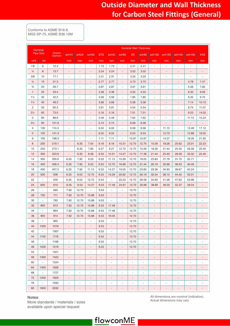
NominalPipe Size Outside
Diameter
Nominal Wall Thickness
sch10 sch20 sch30 STD sch40 sch60 XS sch80 sch100 sch120 sch140 sch160 XXS
NPS DN mm mm mm mm mm mm mm mm mm mm mm mm mm
1/8 6 10.3 - - - 1.73 1.73 - 2.41 2.41 - - - - -
8 13.7 - - - 2.24 2.24 - 3.02 3.02 - - - - -
3/8 10 17.1 - - - 2.31 2.31 - 3.20 3.20 - - - - -
15 21.3 - - - 2.77 2.77 - 3.73 3.73 - - - 4.78 7.47
20 26.7 - - - 2.87 2.87 - 3.91 3.91 - - - 5.56 7.82
1 25 33.4 - - - 3.38 3.38 - 4.55 4.55 - - - 6.35 9.09
1¼ 32 42.2 - - - 3.56 3.56 - 1.85 1.85 - - - 6.35 9.70
1½ 40 48.3 - - - 3.68 3.68 - 5.08 5.08 - - - 7.14 10.15
2 50 60.3 - - - 3.91 3.91 - 5.54 5.54 - - - 8.74 11.07
2½ 65 73.0 - - - 5.16 5.16 - 7.01 7.01 - - - 9.53 14.02
3 80 88.9 - - - 5.49 5.49 - 7.62 7.62 - - - 11.13 15.24
3½ 90 101.6 - - - 5.74 5.74 - 8.08 8.08 - - - - -
4 100 114.3 - - - 6.02 6.02 - 8.58 8.58 - 11.13 - 13.49 17.12
5 125 141.3 - - - 6.55 6.55 - 9.53 9.53 - 12.70 - 15.88 19.05
6 150 168.3 - - - 7.11 7.11 - 10.97 10.97 - 14.27 - 18.26 21.95
8 200 219.1 - 6.35 7.04 8.18 8.18 10.31 12.70 12.70 15.09 18.26 20.62 23.01 22.23
10 250 273.1 - 6.35 7.80 9.27 9.27 12.70 12.70 15.09 18.26 21.44 25.40 28.58 25.40
12 300 323.9 - 6.35 8.38 9.53 10.31 14.27 12.70 17.48 21.44 25.40 28.58 33.32 25.40
14 350 355.6 6.35 7.92 9.53 9.53 11.13 15.09 12.70 19.05 23.83 27.79 31.75 35.71 -
16 400 406.4 6.35 7.92 9.53 9.53 12.70 16.66 12.70 21.44 26.19 30.96 36.53 40.49 -
18 450 457.2 6.35 7.92 11.13 9.53 14.27 19.05 12.70 23.83 29.36 34.93 39.67 45.24 -
20 500 508 6.35 9.53 12.70 9.53 15.09 20.62 12.70 26.19 32.54 38.10 44.45 50.01 -
22 - 559 6.35 9.53 12.70 9.53 - 22.23 12.70 28.58 34.93 41.28 47.63 53.98 -
24 600 610 6.35 9.53 14.27 9.53 17.48 24.61 12.70 30.96 38.89 46.02 52.37 59.54 -
26 - 660 7.92 12.70 - 9.53 - - 12.70 - - - - - -
28 700 711 7.92 12.70 15.88 9.53 - - 12.70 - - - - - -
30 - 762 7.92 12.70 15.88 9.53 - - 12.70 - - - - - -
32 800 813 7.92 12.70 15.88 9.53 17.48 - 12.70 - - - - - -
34 - 864 7.92 12.70 15.88 9.53 17.48 - 12.70 - - - - - -
36 900 914 7.92 12.70 15.88 9.53 19.05 - 12.70 - - - - - -
38 - 965 - - - 9.53 - - 12.70 - - - - - -
40 1000 1016 - - - 9.53 - - 12.70 - - - - - -
42 - 1067 - - - 9.53 - - 12.70 - - - - - -
44 1100 1118 - - - 9.53 - - 12.70 - - - - - -
46 - 1168 - - - 9.53 - - 12.70 - - - - - -
48 1200 1219 - - - 9.53 - - 12.70 - - - - - -
52 - 1321 - - - - - - - - - - - - -
56 1300 1422 - - - - - - - - - - - - -
60 - 1524 - - - - - - - - - - - - -
64 1400 1626 - - - - - - - - - - - - -
68 - 1727 - - - - - - - - - - - - -
72 1500 1829 - - - - - - - - - - - - -
76 - 1930 - - - - - - - - - - - - -
80 1600 2032 - - - - - - - - - - - - -
All dimensions are nominal (indicative).Actual dimensions may vary.
Conforms to ASME B16.9,MSS SP-75, ASME B36.10M
Notes:More standards / materials / sizesavailable upon special request
Outside Diameter and Wall Thicknessfor Carbon Steel Fittings (General)

flowconME
Nominal Pipe-Size
All Fittings 45° / 90°Elbows, Tees &
Crosses
180°Returns Caps
Reduc-ers & LapJoint Stub
Ends
Lap Joint StubEnds
DN NPS DN, DN1,DN2 t, t1, t2 H,F,C,M P K E /
E1 F G R
15-65 ½-2½ +1.6-0.8
Not Lessthan
87.5% ofNominal
Thickness
±1.6 ±6.4 ±6.4 ±3.0 ±1.6 0-0.8
0-0.8
80-90 3-3½ +1.6 ±1.6 ±6.4 ±6.4 ±3.0 ±1.6 0-0.8
0-0.8
100 4 ±1.6 ±1.6 ±6.4 ±6.4 ±3.0 ±1.6 0-1.6
0-1.6
125-200 5-8 +2.3-1.6 ±1.6 ±6.4 ±6.4 ±6.4 ±1.6 0
-0.80
-1.6
250-450 10-18 +4.0-3.0 ±2.3 ±9.6 ±6.4 ±6.4 ±2.3 0
-0.80
-1.6
500-600 20-24 +6.4-4.8 ±2.3 ±9.6 ±6.4 ±6.4 ±2.3 0
-1.6
650-750 26-30 +6.4-4.8 ±3.0 ±9.6 ±4.8 0
-1.6
800-1200 32-48 +6.4
-4.8 ±4.8 ±9.6 ±4.8
1300-1500 52-60 +9.5
-6.4 ±9.5
1600-1700 64-68 +12
-9.5 ±12
1800-2000 72-80 +16
-12 ±16
All dimensions are nominal (indicative).Actual dimensions may vary.
Conforms to ASME / ANSI B16.9
• Limiting tolerances can be different between the different standards and codes.
Tolerance for Butt-Welding Fittings
Viale Abruzzi 94 CAP 20131Milano - Italy
Tel: +39.034.36881209