· abstract nowadays, the existing formalisms to represent software architectures (such as box and...
TRANSCRIPT
ARCHITECTURAL DESCRIPTION OFOBJECT ORIENTED FRAMEWORKS
Gabriela B. Arevalo
Thesis Advisor: Isabelle Borne(Ecole des Mines de Nantes)
August 2000

AA bb ss tt rr aa cc tt
Nowadays, the existing formalisms to represent software architectures (such as box andline drawings) fail in providing a clear semantics and only give an intuitive picture of the system asa whole, which is not enough as a valuable description. More specifically, the frameworkarchitectures should show the overall design and the specification of the points of variability of theframework, making easier the reuse of the architecture, integration with other frameworks and areference to measure the changes in subsequent versions of the frameworks. Starting from severalframeworks, we propose, as a first step, to study and compare the various levels and expressivepower of two formal approaches, such as architectural patterns and Wright –an architecturaldescription language. Next we study the possible complementarity of these approaches, and alsoevaluate the flexibility of the descriptions in order to be able to take evolution aspects into account.The final objective is to propose a complete description of a framework based on the previousresults.


AA cc kk nn oo ww ll ee dd gg ee mm ee nn tt ss
After all this year, I've got quite a list of people who contributed in some way to this thesis,for which I would like to express thanks.
To Isabelle Borne, my thesis advisor, who gave me guidance and support throughout theentire thesis process. Thank you !
To Gustavo Rossi, who involved me in this international program. He also helped methrough many problems, and his opinions helped shape this work. Thank you !
To Annya and Janick, who worked very hard to provide me a good environment to studyand to live in Nantes. Thank you !
To Remi Douence, who shared with me all his knowledge about softwares architectures.Thank you !
To Xavier Alvarez, who helped me with his fruitful discussions to focus the goals of thisthesis. Thank you !
A mis compañeros del LIFIA : Mauricio, Fernando y Ramiro por ayudarme al principio deesta tesis cuando mis conocimientos sobre frameworks era basico y ellos respondieron con muchapaciencia a todas mis preguntas. Thank you !
A mis amigos en Nantes : Sinagi, Andres, Gabriel y Xavier por convertirse en mi familiadurante mi estadia en Nantes. Thank you !
A mis « hermanos postizos » : Guillermo, Anabella, Alejandra y Cristian (en Argentina) yAlejandro y Analia (en Alemania) por bancarme en los buenos y en los malos momentos. Susmails, cartas, postales y la bandera argentina que recibi de regalo hicieron que no sintiera ladistancia fisica con ellos y que el cariño que les tengo crezca dia a dia. Thank you !
A mis mejores amigas Karina y Nora por su cariño y quienes estuvieron siempre presentescon su corazon al lado mio. Thank you !
A mis hermanos Dario, Patricia, Cynthia, Virna y Victor por sus chistes, sus anecdotas ysu alegria que transmitieron por e-mail haciendome sentir como si yo estuviera entre ellos en micasa. Thank you !
Especialmente a Papá y Mamá por apoyarme en este nuevo proyecto de mi vida yalentarme diariamente para que no bajara los brazos ante las adversidades tan sencillas como lade estar lejos fisicamente de mi casa y de Argentina. Sin esa fuerza y ese amor inconmensurableque transmiten en el dia a dia, esta experiencia hubiera sido imposible. A ellos les dedico mitrabajo.
Gabriela Arévalo
August 2000


Table of Contents
Chapter 1: Introduction................................................................................... 131.1 Motivation.........................................................................................................131.2 Current Research .............................................................................................14
1.2.1 Documenting Frameworks using Patterns [Joh92].....................................141.2.2 Design Patterns, Contracts, and Motifs in Concert [LK94]..........................151.2.3 More than design patterns [Ric98].............................................................16
1.3 Architectural Description Language as an alternative formal approach ..............171.4 Related Work ...................................................................................................171.5 Approaches and Contribution ...........................................................................181.6 Organization of the Thesis ................................................................................19
Chapter 2: Software Architectures and Approaches of Description .......... 212.1 Definitions of Software Architecture ..................................................................212.2 Architectural Patterns .......................................................................................222.3 Architectural Styles...........................................................................................24
2.3.1 Practical Benefits of Architectural Styles ...................................................262.4 Architectural Styles and Patterns ......................................................................262.5 Significance of Software Architecture to Software Engineering..........................272.6 Architecture Description Languages (ADLs): General features ..........................27
2.6.1 Architectural Elements and Its Properties..................................................282.6.2 Wright: An Architectural Description Language..........................................30
2.6.2.1 Structure...............................................................................................302.6.2.2 Style .....................................................................................................322.6.2.3 Behaviour: Definition of interaction protocols .........................................332.6.2.4 Validation of Descriptions......................................................................352.6.2.5 Properties .............................................................................................36
2.7 Summary .........................................................................................................36Chapter 3: Object Oriented Frameworks....................................................... 37
3.1 Definition..........................................................................................................373.2 Differences with other concepts ........................................................................373.3 Characterization of Frameworks by different dimensions...................................383.4 Application Frameworks: Specific Features.......................................................393.5 Components and Frameworks ..........................................................................403.6 Keys of Frameworks.........................................................................................41
3.6.1 : Analysis, Design and Code Reuse ..........................................................413.6.2 Hotspots and Frozen Spots.......................................................................41
3.7 Analysis: Goals, Benefits and Weaknesses.......................................................423.7.1 Goals........................................................................................................423.7.2 Benefits ....................................................................................................423.7.3 Weaknesses.............................................................................................43
3.8 Summary .........................................................................................................43Chapter 4: Architectural Description of Frameworks : First Problems ..... 45
4.1 Software Architecture: Level of Abstraction.......................................................454.2 Architectural Description: Conceptual Model .....................................................464.3 Architectural Components = Software Components ? .......................................484.4 Connectors.......................................................................................................494.5 Internal State of the Components......................................................................50
4.5.1 Wright and Abstract Machines B ...............................................................504.5.2 Interaction of the Abstract Machine B with the environment .......................51

4.5.3 Connection between a Wright Component and an Abstract Machine B ......524.5.4 Description of the interaction between a Wright component and an AbstractMachine B ................................................................................................................53
4.5.4.1 Resolution of non-determinism in the connector B .................................554.6 Summary..........................................................................................................56
Chapter 5: Architectural Description OF Object Oriented Frameworks: AnApproach 57
5.1 Introduction.......................................................................................................575.2 MAPPINGS: Definition and Assumptions...........................................................59
5.2.1 Mapping for Classes .................................................................................595.2.2 Mapping for Relationships between Classes..............................................605.2.3 Format for Components and Connectors ...................................................615.2.4 Mapping for the Messages ........................................................................615.2.5 Mapping for Classes' Creation...................................................................625.2.6 Mapping for Conditional Statements ..........................................................63
5.3 Object oriented Architectural Description - First Case: Design and Code ..........645.3.1 Example: Measurements System Framework [Bos00] ...............................64
5.3.1.1 Architecture of the System.....................................................................655.3.1.2 Minimal details about the design............................................................65
5.3.2 First Approach: Use of Predefined Styles ..................................................665.3.3 Second Approach: Use of Steps................................................................67
5.4 Architectural Description – Second Case: Architectural Patterns + WrightDescription ...................................................................................................................73
5.4.1 Example: A Generic Coordination Abstraction for Managing SharedResources [CTN97] ..................................................................................................735.4.2 Requirements ...........................................................................................745.4.3 Solution ....................................................................................................745.4.4 Approach: Use of Steps ............................................................................75
5.5 Summary..........................................................................................................82Chapter 6: Architectural Description Aspects: Discussion ......................... 84
6.1 Analogy between Architectural Style and Framework Architecture.....................846.2 Levels of Description.........................................................................................876.3 Level of Components ........................................................................................886.4 The Potential of the Connectors ........................................................................886.5 Increment of Connectors and Components .......................................................896.6 Management of Errors ......................................................................................896.7 Lack of Expressiveness in Structural Features ..................................................896.8 Lack of Expressiveness of Timing .....................................................................896.9 Dynamic Binding and Creation/Destruction of Components ...............................896.10 Detection of Errors with the Wright Checking Tool .............................................906.11 Use and Discovering of Patterns in the Architectural Description ......................906.12 Properties of Cohesion and Coupling in the Architectural Description ................916.13 Architectural Views ...........................................................................................926.14 Complementaries with other Techniques...........................................................936.15 Summary..........................................................................................................94
Chapter 7: Evolution of Frameworks ............................................................. 957.1 General Overview of the Levels of Abstraction ..................................................957.2 Aspects of Evolution .........................................................................................96
7.2.1 Internal reorganization...............................................................................967.2.2 Changing functionality ...............................................................................98
7.2.3 Extending functionality ..............................................................................997.2.4 Reducing functionality...............................................................................99
7.3 Analysis ......................................................................................................... 1007.4 Summary ....................................................................................................... 100
Chapter 8: Conclusions and Future Research.............................................1018.1 Context .......................................................................................................... 1018.2 Conclusions ................................................................................................... 1028.3 Future Research............................................................................................. 103


List of Figures
Figure 2.1: Architectural Styles in graphic notation ...........................................................24Figure 2.2: Multi-Phase Architectural Style [PW92]...........................................................25Figure 2.3: Hierarchical Structure.....................................................................................31Figure 4.1: Conceptual Modelling of Software Architectures [Now99]................................47Figure 4.2: Component or Connector ? [SG99].................................................................49Figure 4.3: Specification in B of Text_Filter ......................................................................51Figure 4.4: Ports Component and B .................................................................................51Figure 4.5: An Abstract Machine B with its interface .........................................................52Figure 4.6: Two possible connections between a Wright component and an Abstract
Machine B................................................................................................................52Figure 5.1: Composite Pattern..........................................................................................58Figure 5.2: Graphical Relationships between classes .......................................................58Figure 5.3: Class Model for a Book and the Mapping with Connectors and Components...60Figure 5.4: Class Model for a Truck and Representation with Components and
Connectors ..............................................................................................................61Figure 5.5: Architecture of the Measurement System Frameworks ...................................65Figure 5.6: Master / Slave Pattern ....................................................................................67Figure 5.7: Class Model for the Shared Resource Access Policy ......................................75Figure 5.8: Example of Application of Layers Architectural Pattern ...................................76Figure 5.9: The developed algorithms seen graphically ....................................................81Figure 6.1: Growth of the Architectural Description in X-Y axis .........................................87Figure 7.1: Software Evolution at Three Levels of Abstraction ..........................................96


1.1 Motivation
An object oriented framework is a kind of reusable software architecture comprising bothdesign and code. More specifically, [Mat96] defines an object oriented framework as a generativearchitecture for maximum reuse represented as a collective set of abstract and concrete classes,encapsulating potential behaviour for subclassed specializations.
One critical issue for users and implementors of a framework is the documentation thatexplains what the framework provides and what is required to instantiate it correctly for someapplication. Typically, a framework is specified using a combination of informal and semi-formaldocumentation. On the informal side are guidelines and high-level descriptions of usage scenarios,tips and examples [SG99]. If an object oriented methodology such as UML [UML] was used todocument the framework, there are class and collaboration diagrams as a description artefacts.These approaches tend to be informal and idiosyncratic, consisting of box-and-line diagrams thatconvey the essential system structure, together wil the prose that explains the meaning of thesymbols [MKMG96]. On the semi-formal side one usually finds a description of an applicationprogrammer's interface (API) that explains what kinds of services are provided by the framework.APIs are formal to the extent that they provide precise descriptions of those services -usually as aset of signatures, possibly annotated with informal pre and post-conditions [SG99].
Such documentation is clearly necessary. However, by itself it leaves many importantquestions unanswered -for component developers, system integrators, framework implementors,and proposers of new frameworks. For example, the framework API may specify the names andparameters of services provided by the infrastructure. However, it may not be clear what are therestrictions (if any) on the ordering of invocations of those services. Usage scenarios may help, butthey only provide examples of selected interactions, requiring the reader to infer the general rule.Moreover, it may not be clear what facilities must be provided by the parts added to the framework,and which are optional. [SG99].
As with most forms of informal system documentation and specification, the situation couldbe greatly improved if one had a precise description as a formal specification of the framework.However, a number of critical issues arise immediately. What aspects of the framework should bemodeled ? How should that model be structured to best expose the architectural design ? Howshould one model the parts of the framework to maintain traceability to the original documentation,and yet still improve clarity ? How should one distinguish optional from required behaviour ?[SG99] For object oriented frameworks what aspects of the object-oriented design should beexposed in the formal model ? . The model show answer questions as the following ones: Whichnew classes must be provided for the framework ? What classes should be used from theframework ? Which operations must be called and which operations are often called in theframework ? What classes must be subclassed ? Which operations must be overriden and whichoperations are often overriden? [Mat96].
CChhaapptteerr 11:: II nn tt rr oo dd uu cc tt ii oo nn
14 Object Oriented Architectural Description of Frameworks
About describing framework architectures, [Joh92] denotes that "nobody understands aframework until they have used it". There are several reasons to have an architecturaldescription of a framework based on high-level interfaces and interactions, andcharacterizing their semantics in terms of protocols:
⇒ 'Selling' the framework: Prospective users of the framework want a generalunderstanding of the framework in order to decide if it is appropriate for their needs. Thiskind of description should show the overall design and the points of variability of theframework. [Ric98].
⇒ Reuse of architecture: Transmitting a language-independent view of the architectureallows the high-level design of the framework to be reused in implementing it in otherlanguages, or in modifying it for use in other domains. [Ric98]
⇒ Integration of frameworks: In order to facilitate the construction of systems fromseveral existing frameworks, the architectural assumptions of each framework should bemade explicit. [GAO95] [MB00]
⇒ Evolution and re-engineering: Having an architectural description of a framework givesus a reference against which one can measure the changes in subsequent versions ofthe framework. In the same way, the ability to describe the architecture of an applicationallows us to form hypothesis about the architecture which can be tested in the process ofreverse engineering. [MN97]
This thesis aims to propose a complete description of a framework using the followingformal approaches: architectural patterns and Wright [All97] -an architectural descriptionlanguage. The steps to fulfill this objective consist of studying and comparing the various levelsand expressive power of approaches, also studying the possible complementarity and flexibility ofthese approaches in order to be able to take evolution aspects into account.
1.2 Current Research
There are no well-established rules for describing framework. Thus, different approacheshave been proposed focusing mostly on informal techniques. We will enumerate some of them,where the ideas are similar to our approach: the use of several artifacts of domain analysis andobject oriented design to give different views of a framework's architecture.
1.2.1 Documenting Frameworks using Patterns [Joh92]
This approach deals with the frameworks description using pattern language. A patternlanguage is a set of patterns, where each of them describes how to solve a particular kind ofproblem. The main idea is to start from a very large scale and going into further details from patternto pattern. The approach is based on the fact that the framework users want to know as little aspossible about the framework. Thus, patterns have to go through all functionality of the frameworkfrom a general presentation to more precise features and then progressively to describe which thehotspots and the collaboration contracts are. This approach fulfills its three purposes of thedescription of:
• the purpose of the framework: It must be the first thing that the documentationdescribes. If the framework turns out to be inappropriate then the reader does not haveto continue reading. The first pattern describes its application domain. It acts as a entrycatalog for the framework and a road map regarding the rest of patterns
• how to use the framework: The patterns give a kind of cookbook, giving detailedinstructions for using the frameworks.
• the detailed design of the framework: This information not only includes the differentclasses in the framework but also the way that the instances of these classes

Chapter 1: Introduction 15
collaborate. The ideas is to treat the set of patterns as a directed graph, using thereferences from one pattern to another as the edges, and to place design information asfar from the first pattern as was feasible.
The use of examples in this approach makes frameworks more concrete, makes it easierto understand the flow of control, and helps the reader to determine whether he or sheunderstands the rest of documentation.
Summarizing up, patterns are an informal technique aimed primarily at describing how touse a framework, not describing its algorithms, patterns of collaboration or shared invariant. Theyjust describe specific points of the framework supported by examples.
1.2.2 Design Patterns, Contracts, and Motifs in Concert [LK94]
This approach develops a multi-layered model for framework reuse which comprises reuseobjects at different levels of abstraction and varying degrees of encapsulation, most notably,microarchitectures. It integrates design patterns, contracts, and motifs as techniques for therepresentation and documentation of microarchitectures and frameworks. It also suggests a designguided by the design of the underlying framework and possibly of its subframeworks and that amixed top-down/bottom-up approach be taken.
[GHJV95] detected that there were redundant design structures into the framework andintroduced the concept of microarchitectures as a set of classes and its interactions. Asframeworks codify design knowledge of a particular domain, microarchitectures codify knowledgein terms of the behavior of object collaborations. Microarchitectures comprise both the design andcode of the classes involved and the interactions and control flow among them. These structuresare of course known by the framework designers, but unfortunately by very few others. Designpatterns are a mechanism to express how component interrelate as well as high-levelrepresentation technique for properly capturing and expressing design experience and intent toultimately facilitate design reuse. They can be described in an informal, template-based manner.But the design patterns describe the framework design at a very high level. To ease the derivationof concrete designs from them, a contract - a construct for specifying interactions among groups ofobjects - is used as an intermediate representation between a microarchitecture and itscorresponding design patterns. Contracts used to describe frameworks provide the applicationdesigner with:
• A vocabulary with which to describe the application;• Through conformance declarations, the identification of the application-specific classes,
variables, methods, and hooks for customization, all necessary for identifying,maintaining and implementing a behavioral composition;
• Knowledge of, and a better understanding of, individual microarchitectures present in theunderlying framework, thus improving the understanding of the overall framework;
• Guidance when refactoring affects participants in a contract. Contracts should not betaken as a means to understand the functionality of classes and methods.
More oriented to novice users, the motifs show how to use the framework. Each of themdescribes a situation which must be replicated in order to use the framework. A set of motifsdescribe the underlying class framework and an example application.
To put all the techniques together, this approach covers a documentation with:• The purpose of and how to use the underlying framework;• The purpose of and how to reuse the application examples;• The design of the framework
Motifs are responsible for describing the first two items, whereas design patterns andcontracts address the last item. Thus motifs complement design documentation doing it soinformally without detailing algorithms or object collaborations. Instead they often refer to designpatterns and/or contracts. To support documentation from lower level of a framework, each class(and even if it is possible, also the individual methods) should have references to motifs, designpatterns, and/or contracts it is involved in.
16 Object Oriented Architectural Description of Frameworks
With this proposal, they discover that design patterns, contracts, and motifs, along with thecorresponding code components, classes and methods, must cross reference each otherwhenever appropriate.
1.2.3 More than design patterns [Ric98]
This approach analyzes the insufficiency of design patterns to get an architecturaldescription of a framework. Considering the selling issue, design patterns do not describe what wecan do with the framework, how we can tailor the framework to create a variety of applications.Taking into account reuse issue, reusing a framework implies understanding the domain-specificarchitecture that the framework offers, knowing how it models the problem domain, and what themodel components of the system and their relationships . Indeed the granularity of design patternsis generally very fine and is not always suited to the granularity of the main components of aframework. For example, behavioral patterns ([GHJV95]) are more architectural in the sense thatthey describe a relationship between entities which could be seen as an infrastructure for acomplete application, rather than a relationship which is based solely on inheritance. About theintegration of frameworks, design patterns do not give us the context in which the framework isexpected to be used . Finally about the evolution issue, it is possible to observe a change of designpatterns without having a real evolution of the architecture. Thus design patterns are not a goodgauge for following the evolution of a framework.
The main problems are incompleteness, because design patterns can not document all thedesign decisions emanating from the requirements, and its fine granularity, because designpatterns overly describe the system, without revealing a more global view of the system.
[Ric98] believes that unlikely one notation or method can be used to express all aspects ofan application's architecture. To cope with this, she proposes a variety of complementary forms ofdocumentation to understand the what - the context: what is the application domain, what are itsmain elements and their interrelationships, what problems must be tackled in building theframework architecture - and the how - the solution: how the framework designers have chosen totackle these problems.
• Application domain model: as a result of a domain analysis, it is necessary to identifydomain concepts and making the relationships between them explicit.
• Design space for the domain: each problem in the domain can be solved using a varietyof approaches. In a design space each problem represents an axis along which arepossible or recommended solutions [DMNS97]. Understanding the design space allowsus to situate the particular framework as a point in this space
• Examples: they illustrate what kinds of applications can be created using the framework.They show the variability in the framework.
• Architectural patterns: they present us with a metaphor - client/server, pipe/filter, etc -for architectural view, or a large part of one. Such metaphors can succinctly describecomponents, the relationships between them, and at the same time provide us withfamiliar scenarios for their behavior.
• Scenarios: They are instances of use-cases. They show how several components (i.e.granularity greater than classes) interact to assure one variation of the system'sfunctionality.
These forms of description aim to give an understanding of the system at a coarsegranularity and can complement more detailed forms of documentation such as design pattern andclass hierarchies.

Chapter 1: Introduction 17
1.3 Architectural Description Language as an alternative formalapproach
All the proposed approaches are focused on informal techniques. In spite that they can beefficient enough to communicate design decisions, they have limitations to represent the realsemantics of different parts of a framework. [AAG93] explains that the imprecision produced bybox-line drawings makes it difficult to attach unambiguous meanings to the descriptions. It may bedifficult to know when an implementation agress with the more abstract description. It is virtuallyimpossible to reason formally about the descriptions. It is difficult to compare two differentdescriptions even for the same interpretation.
Thinking in terms of giving meaning to the descriptions of software systems, ArchitecturalDescription Languages (ADLs) have been proposed to support architecture-based development,formal modelling notations and analysis and development tools that operate on architecturalspecifications [MT97]. ADL must be able to communicate the architectural structures involvedwithin a system to all stakeholders. The level of granularity, or abstraction, must be flexible enoughto allow descriptions in sufficient detail or abstraction dependent on the users of the architecturaldescription [All97].
The benefits of an architectural analysis are enhanced by precise semantics. Elimination ofambiguity is paramount in any architectural description to accurately describe a system. Thisrequirementmust be balanced with the competing goals of allowing informal descriptions [Bro00].
This dissertation works with Wright ADL [All97] to infer a possible architectural descriptionof some object oriented frameworks, whose design and use documentation is composed of a set ofinformal artifacts or the code itself. We do not claim that the described techniques in the previoussection are incomplete. In fact our approach searches to be an union of complementarymethodologies (Wright ADL [All97] and architectural patterns) and also represent a complementwith the rest of techniques to give a semantic description, and avoiding as much as possible theambiguity of box-line drawings in the documentation.
1.4 Related Work
The particular combination in the use of formal languages to describe an object orientedframework is only shown in [SG99]. In this work, they develop a specification of Sun's EnterpriseJava-Beans. Firstly, they show formal architectural models based on protocols clarifying the intentof an integration framework, as well as exposing critical properties of it. Secondly, they describetechniques to create the model, and structure it to support traceability, tractability, and automatedanalysis. This work is a good approximation on ways to provide formal architectural models ofobject oriented frameworks.
Another related area is research on the analysis of architectural standards. In [AGI98] theylooked at the high level architecture (HLA) for distributed simulation. HLA defines an integrationstandard for multi-vendor distributed simulations. They demonstrated that Wright could be used tomodel this framework and eliminate potential flaws in the HLA design.
Another area is work on protocol specification and analysis. There has been considerableresearch on ways to specify protocols using a variety of formalisms, including I/O Automata [LT89],SMV [CES85], SDL [Hol90] and Petri Nets [Pet77]. Most protocol analysis assumes one isstarting with a complete description of the protocol. The problem is then to analyze that protocol forvarious properties. In contrast, in architectural modelling of systems , protocols are typically implicitin the APIs described in the framework documentation. Discovering what that the protocols are,and how they determine the behaviour of the system is itself a key challenge.
18 Object Oriented Architectural Description of Frameworks
Considering that the comparison between different architectural description languages canbe made using benchmark problems, [AG96] proposes AEGIS Weapons System as a candidateproblem. In this work, they show that while (architecturally speaking) the constructed system wasrelatively simple –less than a dozen architectural components- during the course of construction, itraised a surprisingly number of thorny architectural problems for the system implementors andintegrators. Using Wright ADL [All97], they show that an architectural formalism helps to exposeand solve some of the architectural problems.
With a different viewpoint and closer to the approach of this dissertation, [Men00] proposesa logic-meta programming to develop an expressive architectural model, algorithm and prototypetool for automatically checking conformance of the implementation of a software system to one ofmore architectural views. This approach is confined to static conformance checking only becausethe reasoning is about the static structure of a software implementation, and does not take run-timeinformation into account.
1.5 Approaches and Contribution
This dissertation is concerned to get an architectural description about object orientedframeworks, whose documentation is based on informal techniques or the documentation is thecode itself, using the Wright ADL [All97] as the main tool and architectural patterns as acomplementary one. To fulfill this requirement, the following steps are made:
⇒ Firstly, all the features related to the concepts of software architectures, ADLs andformal approaches of description are studied. Thus, we get a complete context of theelements that we apply and use in the frameworks.
⇒ Secondly, main features of building/using an object oriented framework are also studied.We need to know how the frameworks are thought and how they evolve, in this way, weobtain the elements and the relationships that are represented (if possible) with theformal approaches of description. We also study documentation made with designand/or code itself of real frameworks.
⇒ The third step is the mapping from the information about the frameworks to anarchitectural description. If possible, we map also to an architectural pattern to see if thismapping can give us more information about the studied frameworks. Thus, we define aset of rules that an architect can follow to infer a possible architectural description. To dothis last step the developed approach will consider some ideas presented in [LK94] . Inthis approach, they identify different levels of reuse and abstraction in a framework. Ourapproach considers different levels of abstraction to get an architectural description ofthe different parts of a framework and successively refinements from general to specificaspects to be very close to the implementation
⇒ The fourth step consists of analyzing the results from the third step to know whatproperties we could get using formal approaches of description applied on frameworks.We also consider if the formal approaches can be a complement to more known informaltechniques of description
⇒ The fifth step is the study of evolution impacts on an architectural description of anobject oriented framework considering the developed approach.
The contributions of this dissertation are:⇒ The definition of rules to define a mapping from informal documentation of frameworks
to an architectural description. Thus, firstly, the path from documentation and/or code toan architectural description of a framework is reduced to a recipe. Secondly the mappingallows us identify microarchitectures and architectural components and connectorsrelated to the framework. Finally, we obtain a generic software architecture that capturesthe family of applications resulting from the framework instantiation.

Chapter 1: Introduction 19
⇒ The analysis of how efficient an ADL is to 'capture' the ambiguities caused by informaltechniques.
⇒ The focus on a formal approach only can be a 'wrong' step in the idea of avoidingambiguous descriptions
⇒ The proof that an ADL can be a complement to other informal and formal techniques.Thus, we get a uniform model of frameworks description that allows the users of theframework understand the abstract design of the underlying framework as well as theinternal structure of its classes, in order to adapt and extend them.
⇒ The analysis of the evolution impacts of frameworks in the architectural descriptions.
1.6 Organization of the Thesis
This dissertation is organized in the following way: Chapter 2 describes the main featuresand formal approaches of description of software architectures. Chapter 3 describes generalfeatures about frameworks. Chapter 4 presents a previous analysis of problems found during theprocess of searching common points between software architectures and object orientedframeworks. Based on this analysis, Chapter 5 presents the developed mapping with thealgorithms and two cases studies with their results. Chapter 6 shows a discussion of someimportant aspects of the developed approach and a discussion related to the results obtained inthe previous chapter. Chapter 7 shows the evolution impacts of frameworks in resulting formaldescription. Finally, Chapter 8 presents the conclusions and future work.

20 Object Oriented Architectural Description of Frameworks
During last ten years software architecture has begun to emerge as an important field ofstudy for software engineering practitioners and researchers. This emergence is evidenced by alarge body of work in areas such as domain specific architectures, architectural descriptionlanguages, formal underpinnings for architectural design, and architectural design environments.To understand what aspects and what tools are being addressed, this chapter intends to give thereader a complete overview of this discipline.
We start clarifying the definition of software architectures to keep one of them that it isconsidered in the rest of this dissertation. Afterwards, we define and present the most knownclassical architectural patterns and styles, and we show their features and the context where theyare applied. These conditions are important for this dissertation because we intend to identify themin the studied object oriented frameworks. Finally we show the main characteristics and propertiesof ADLs to describe software architectures and we also present Wright ADL (our work tool)analyzing which features of an ‘ideal’ ADL the language fullfils and which not.
2.1 Definitions of Software Architecture
The main problem in the field of software architecture is the lack of a clear definition ofwhat an architecture is. Let's see the different approaches found in the literature. [GS92] considersthat sofware architecture is emerging as a significant and different design level. According to[LC98] software architecture may then be basically defined as a description of the structural anddynamic properties of a system at a high level of abstraction.
But the software architecture is also concerned with issues such as the global controlstructure of a system, its main design elements and the way they share functionalities, the waydesign elements communicate (protocols for communication, synchronization, data access), thephysical distribution of design elements, scaling and performance. Following this approach, one ofthe earliest definitions can be found in [PW92], where the software architecture is modeled withelements, form and rationale. Elements are either processing elements (e.g. procedures, filters),data elements (e.g. set of global variables), or connecting elements (e.g. procedure calls,messages). A form is defined by the constraints on the elements and the rationale captures themotivation for the choice of elements, form and architectural style. There is a more restrictivedefinition of software architecture given in [GS92], which only involves computational componentsand a description of interaction between these components which respectively correspond toprocessing elements and connecting elements and some part of form as defined in [GS92]. Amore practical definition is the following : an abstract system specification consisting primarily offunctional components described in terms of their behaviours and interfaces and interactionsbetween components [HR94]. A fourth definition is extracted from [GP95] and synthesizes theprevious ones : a software architecture is the structure of the components of a program/system,their interrelationships (often called connectors [SG96]), and principles and guidelines governingtheir design and evolution over time.
Clearly, from all the definitions given previously, a fact is software architecture focuses onraising the level of abstraction at which developers can reason about their systems. A system'sarchitecture provides a model of the system that suppresses implementation detail and increases
CChhaapptteerr 22:: SSooff ttwwaarree AArrcchhii tteeccttuurreess aannddAApppprrooaacchheess ooff DDeessccrr iipptt iioonn
22 Object Oriented Architectural Description of Frameworks
the independence of system components, allowing many issues to be localized. Then thearchitecture can concentrate on the analyses and decisions that are most crucial to the systemstructure [All97].
An important remark is that a feature that distinguishes of software architecture from otherviews of the system is the explicit modelling of connectors. While components are thecomputational entities, connectors mediate and govern interactions among components. In thisway connectors separate computation from communication, minimise componentinterdependencies and facilitate system understanding, analysis and evolution [MT97].
This dissertation considers the concepts of components and connectors explicilty torepresent a framework architecture. The proposed approach works on different levels ofabstraction refining the components and connectors, allowing refinement views of a possiblesoftware architecture and identifying architectural patterns or styles and proposing new ones (ifnecessary) which represent the family of applications that can be obtained instantiating theframework.
2.2 Architectural Patterns
In this section we introduce some architectural patterns and some general features. As wesaid previously, we propose to identify their existence in the frameworks. To do this, it is necessaryto know the context where they can be applied. We will not discuss in detail about each of them.Detailed information can be found in [BMR+96].
Architectural patterns express fundamental structural organization schemas for softwaresystems. They provide a set of predefined subsystems, specify their responsibilities, and includerules and guidelines for organizing the relationships between them.
Architectural patterns represent the highest-level patterns in the pattern system presentedin [BMR+96]. They help you to specify the fundamental structure of an application. Everydevelopment activity that follows is governed by this structure -for example, the detailed design ofsubsystems, the communication and collaboration between different parts of the system, and itslater extension. Each Architectural Pattern helps you to achieve a specific global system property,such as the adaptability of the user interface. Patterns that help to support similar properties canbe grouped into categories. [BMR+96] proposes four categories:
• From mud to structure: patterns in this category help you to avoid a 'sea' ofcomponents or objects. In particular, they support a controlled decomposition of anoverall system task into cooperating subtasks.
o Layers pattern helps to structure applications that can be decomposed intogroups of subtasks in which each group of subtasks is at a particular level ofabstraction.
o Pipes and Filters pattern provides a structure for systems that process astream of data. Each processing step is encapsulated in a filter component.Data is passed through pipes between adjacent filters. Recombining filtersallows you to build families of related systems.
o Blackboard pattern is useful for problems for which no deterministic solutionstrategies are known. In Blackboard several specialized subsystems assembletheir knowledge to build a possibly partial or approximate solution.
• Distributed Systems: The Broker pattern provides a complete infrastructure fordistributed applications. The Microkernel and Pipes and Filters patterns only considerdistribution as a secondary concern.
o Pipes and Filters pattern: This pattern is more often used for structuring thefunctional core of an application than for distribution.
o Microkernel pattern applies to software systems that must be able to adapt tochanging system requirements. It separates a minimal functional core from
Chapter 2: Software Architecture and Approaches of Description 23
extended functionality and customer-specific parts. The microkernel alsoserves as a socket for plugging in these extensions and coordinating theircollaboration. Microkernel systems employ a Client-Server architecture inwhich clients and servers run on top of the microkernel component. The mainbenefit of such systems, however, is in design for adaptation and change.
o Broker pattern can be used to structure distributed software systems withdecoupled components that interact by remote service invocations. A brokercomponent is responsible for coordinating communication, such as forwardingrequests, as well as for transmitting results and exceptions.
• Interactive Systems: Model-View-Controller and Presentation-Abstraction-Controlpatterns. Both patterns support the structuring of software systems that feature human-computer interaction.
o Model-View-Controller pattern divides an interactive application into threecomponents. The model contains the core functionality and data. Viewsdisplay information to the user. Controllers handle user input. Views andcontrollers together comprise the user interface. A change-propagationmechanism ensures consistency between the user interface and the model.
o Presentation-Abstraction-Control pattern defines a structure for interactivesoftware systems in the form of a hierarchy of cooperating agents. Every agentis responsible for a specific aspect of the applications's functionality andconsists of three components: presentation, abstraction, and control. Thissubdivision separates the human-computer interaction aspects of the agentfrom its functional core and its communication with other agents.
• Adaptable Systems: Reflection and Microkernel patterns strongly support extension ofapplications and their adaptation to evolving technology and changing functionalrequirements.
o Microkernel pattern applies to software systems that must be able to adapt tochanging system requirements. It separates a minimal functional core fromextended functionality and customer-specific parts. The microkernel alsoserves as a socket for plugging in such extensions and coordinating theircollaboration.
o Reflection pattern provides a mechanism for changing structure and behaviorof software systems dynamically. It supports the modification of fundamentalaspects, such as type structures and function call mechanisms. In this pattern,an application is split into two parts. A meta level provides information aboutselected system properties and makes the software self-aware. A base levelincludes the application logic. Its implementation builds on the meta level.Changes to information kept in the meta level affect subsequent base-levelbehavior.
In the approach presented in this dissertation, the architectural patterns will be consideredin the top level of the description. As we said previously, we will work in different levels ofabstraction and description, refining each level. The architectural patterns are useful in the topmostlevel because they give an global overview of an architecture that has to be specified and refined.[BMR+96] says that the selection of an architectural pattern should be driven by the generalproperties of an application at hand. But most software systems, however, cannot be structuredaccording to a single architectural pattern. They must support several system requirements thatcan only be addressed by different architectural patterns. For example, you have to design both forflexibility of component distribution in a heterogeneous computer network and for adaptability oftheir user interfaces. You can combine Broker and Model-View-Controller patterns. The Brokerpattern provides the infrastructure for the distribution of components, while the model of the MVCpattern plays the role of a server in the Broker infrastructure. Similarly, controllers take the roles ofclients, and views combine the roles of clients and servers, as clients of the model and servers ofthe controllers. In the approach developed in this dissertation, we are inferring a frameworkarchitecture based on design and code, and in fact we map possible architectural patterns which
24 Object Oriented Architectural Description of Frameworks
fits better to our proposed architecture. But not all the cases will allow us to map to them becausethe selection of an architectural pattern, or a combination of several, is only the first step whendesigning the architecture of a system. And our approach is more oriented to use design decisionsthat already have been taken, and if they did not assume any architectural pattern, it will be adifficult task to detect and infer them.
2.3 Architectural Styles
While a software architecture is defined by a layout of architectural elements, anarchitectural style consists of a set of shared assumptions and constraints across a family ofsoftware architectures [GCBA95]. The interest of a particular style is related to its ability toencapsulate important classes of design decisions and to emphasize important constraints onarchitectural elements.
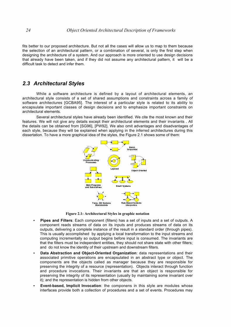
Several architectural styles have already been identified. We cite the most known and theirfeatures. We will not give any details except their architectural elements and their invariants . Allthe details can be obtained from [SG96], [PW92]. We also omit advantages and disadvantages ofeach style, because they will be explained when applying in the inferred architectures during thisdissertation. To have a more graphical idea of the styles, the Figure 2.1 shows some of them:
Figure 2.1: Architectural Styles in graphic notation
• Pipes and Filters: Each component (filters) has a set of inputs and a set of outputs. Acomponent reads streams of data on its inputs and produces streams of data on itsoutputs, delivering a complete instance of the result in a standard order (through pipes).This is usually accomplished by applying a local transformation to the input streams andcomputing incrementally so output begins before input is consumed. The invariants arethat the filters must be independent entities, they should not share state with other filters;and do not know the identity of their upstream and downstream filters.
• Data Abstraction and Object-Oriented Organization: data representations and theirassociated primitive operations are encapsulated in an abstract type or object. Thecomponents are the objects called as manager because they are responsible forpreserving the integrity of a resource (representation). Objects interact through functionand procedure invocations. Their invariants are that an object is responsible forpreserving the integrity of its representation (usually by maintaining some invariant overit); and the representation is hidden from other objects.
• Event-based, Implicit Invocation: the componens in this style are modules whoseinterfaces provide both a collection of procedures and a set of events. Procedures may
Chapter 2: Software Architecture and Approaches of Description 25
be called in the usual way. But in addition, a component can register some of itsprocedures with events of the system. This will cause these procedures to be invokedwhen those events are announced at run time. Thus the connectors in an implicitinvocation system include traditional procedure call as well as bindings between eventannouncements and procedure calls. The invariant: The announcers of events do notknow which components will be affected by those events. Thus components can notmake assumptions about order of processing, or even about what processing, will occuras a result of their events.
• Layered Systems: A layered system is organized hierarchically, each layer providingservice to the layer above it and serving as a client to the layer below. In some layeredsystems inner layers are hidden from all except the adjacent outer layer, except forcertain functions carefully selected for export. The connectors are defined by theprotocols that determine how the layers will interact. Topological constraints includelimiting interactions to adjacent layers.
• Repositories: In this style there are two quite distinct kinds of components: a centraldata structure represents the current state, and a collection of independent componentsoperate on the central data store. Interactions between the repository and its externalcomponents can vary significantly between systems. The choice of control disciplineleads to major subcategories. If the types of transactions in an input stream oftransactions trigger selection of processes to execute, the repository can be a traditionaldatabase. If the current state of the central data structure is the main trigger of selectingprocesses to execute, the repository can be a blackboard.
• Table Driven Interpreters: In an interpreter organization a virtual machine is producedin software. An interpreter includes the pseudo-program being interpreted and theinterpretation engine itself. The pseudo-program includes the program itself and theinterpreter's analog of its execution state (activation record). The interpretation engineincludes both the definition of the interpreter and the current state of its execution. Thusan interpreter generally has four components: an interpretation engine to do the work, amemory that contains the pseudo-code to be interpreted, a representation of the controlstate of the interpretation engine, and a representation of the current state of theprogram being simulated.
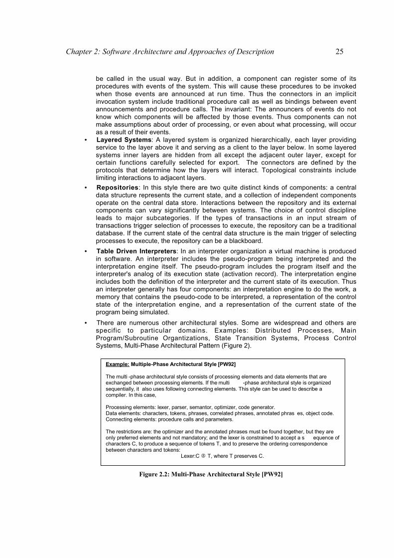
• There are numerous other architectural styles. Some are widespread and others arespecific to particular domains. Examples: Distributed Processes, MainProgram/Subroutine Organtizations, State Transition Systems, Process ControlSystems, Multi-Phase Architectural Pattern (Figure 2).
Example: Multiple-Phase Architectural Style [PW92] The multi -phase architectural style consists of processing elements and data elements that are exchanged between processing elements. If the multi -phase architectural style is organized sequentially, it also uses following connecting elements. This style can be used to describe a compiler. In this case, Processing elements: lexer, parser, semantor, optimizer, code generator. Data elements: characters, tokens, phrases, correlated phrases, annotated phras es, object code. Connecting elements: procedure calls and parameters.
The restrictions are: the optimizer and the annotated phrases must be found together, but they are only preferred elements and not mandatory; and the lexer is constrained to accept a s equence of characters C, to produce a sequence of tokens T, and to preserve the ordering correspondence between characters and tokens:
Lexer:C ! T, where T preserves C.
Figure 2.2: Multi-Phase Architectural Style [PW92]
26 Object Oriented Architectural Description of Frameworks
Observing the features of the different architectural styles, we can enumerate the basicproperties they have:
⇒ They provide a vocabulary of design elements -component and connector types such aspipes, filters, clients, servers, parsers, databases, etc. [Gar95].
⇒ They define a set of configuration rules -or topological constraints -that determine thepermitted compositions of those elements. For example, the rules might specify that aclient-server organization must be an n-to-n relationship, or define a specificcompositional pattern such as a pipelined decomposition of a compiler [Gar95].
⇒ They define a semantic interpretation, whereby compositions of design elements,suitably constrained by the configuration rules, have well-defined meanings [Gar95].
⇒ They define analyses that can be performed on systems built in that style. For example,a deadlock for client-server message passing [RJFC94].
Generally speaking, an architectural style expresses a particular kind of fundamentalstructure for a software system together with an associated method that specifies how to constructit. An architectural style also comprises information about when to use the architecture it describes,its invariants and specializations, as well as the consequences of its application.
We have cited 'pure' architectural styles. It is important to understand the individual natureof each of these styles, most systems typically involve some combination of several styles. Thereare different ways in which architectural styles can be combined [Gar95]:
⇒ Through hierarchy: A component of a system organized in one architectural style mayhave an internal structure that is developed a completely different style. For example, inan UNIX pipeline the individual components may be represented internally using anotherpipe and filter system.
⇒ To allow a single component to use a mixture of architectural connectors. For example,a component might access a repository through part of its interface, but interact throughpipes with other components in a system, and accept control information throughanother part of its interface. In fact, UNIX pipe and filter systems do this, the file systemplaying the role of the repository and initialization switches playing the role of control.
⇒ To completely elaborate one level of architectural description in a completely differentarchitectural style.
2.3.1 Practical Benefits of Architectural Styles
The principled use of architectural styles has a number of practical benefits [Gar95].⇒ it promotes design reuse: routine solutions with well-understood properties can be
reapplied to new problems with confidence.⇒ It can lead to significant code reuse: often the invariant aspects of an architectural style
lend themselves to shared implementations.⇒ It is easier for others to understand a system's organization if conventionalized
structures are used. For example, characterization of a system as a layered organizationimmediately conveys a strong image of the kinds of pieces which collaborates throughservices in different levels of the system.
⇒ Constraining the design space, an architectural style often allows specialized, style-specific analyses. For example, it is possible to analyze pipe-filter systems forschedulability, throughput, latency, and deadlock-freedom
2.4 Architectural Styles and Patterns
Architectural styles are very similar to the architectural patterns presented in [BMR+96]. Infact, every architectural style can be described as an architectural pattern. For example, the Multi-

Chapter 2: Software Architecture and Approaches of Description 27
phase architectural style [PW92] corresponds to the Pipes and Filters pattern [BMR+96]. On theother hand, architectural styles differ from patterns in several important respects:
Architectural styles only describe the overall structural framework for applications. Patternsfor software architecture, however, exist in various ranges of scale, beginning with patterns fordefining the basic structures of an application (architectural patterns) and ending with patterns thatdescribe how to implement a particular design issue in a given programming language (idioms)[BMR+96].
Architectural styles are independent of each other, but a pattern depends on the smallerpatterns it contains, on the patterns with which it interacts, and on the larger patterns in which it iscontained [Ale76]
Patterns are more problem-oriented than architectural styles. Architectural stylesexpresses design techniques from a viewpoint that is independent of an actual design situation. Apattern expresses a very specific recurring design problem and presents a solution to it, all fromthe viewpoint of the context in which the problem arises [BMR+96].
2 . 5 Significance of Software Architecture to SoftwareEngineering
A principled use of software architecture can have a positive impact on at least fouraspects of software development:
• Understanding: Software Architecture simplifies our ability to comprehend large systemsby presenting them at a level of abstraction in which all the system can be understood[GS92] [PW92]. Moreover, architectural description exposes the high level constraints onsystem design as well as the rationale for making specific architectural choices [GP94].
• Reuse: Architectural description support reuse at multiple levels. While most currentwork on reuse focuses on component libraries, architectural design supports, in addition,both reuse of large components (such as subsystems), and also the complementaryneed for reusable frameworks into which components can be integrated [GP94].
• Evolution: Software architecture can expose the dimensions along which a system isexpected to evolve. By making explicit what are the "load-bearing walls" of a system,system maintainers can better understand the ramifications of changes, and therebymore accurately estimate costs of modifications [PW92].
• Analysis: Architectural description provides new opportunities for analysis [PW92],including high-level forms of system consistency checking [AG94], conformance to anarchitectural style [AAG93], and domain-specific analysis for architectures that conformto specific styles [GP94].
2.6 Architecture Description Languages (ADLs): Generalfeatures
In this dissertation, we use Wright ADL [All97] to propose an architectural description of aframework. Firstly, we discuss general features about ADL, and after we describe briefly theelements and ways of working with Wright ADL [All97].
This field seems to be another item in the list of unclear definitions. Nobody agrees in theresearch community on what is an ADL, what aspects of an architecture should be modeled in anADL, and which ADL fits for a particular problem.

28 Object Oriented Architectural Description of Frameworks
ADLs have been proposed as the answer to support architecture-based development,formal modelling notations and analysis and development tools that operate on architecturalspecifications.
An ADL is a language that provides features for modeling a software system's conceptualarchitecture. A number of ADLs have been proposed for modeling architectures both within aparticular domain and as general-purpose architecture modeling languages, for example, Aesop[GAO94], MetaH [Ves96], LILEANNA [Tra93], ArTek [TLPD95], C2 [ MORT96, MTW96], Rapide[LKA+96,LV95], Wright [All97], UniCon [SDK+95], Darwin [MDEK95, MK96], and SADL [MQR95].
ADLs provide a concrete syntax and a conceptual framework for characterizingarchitectures [GMW97]. The building blocks of an architectural description are : components,connectors, and architectural configurations (or topologies). An ADL must provide the means fortheir explicit specification. An ADL typically subsume a formal semantic theory. That theory is partof an ADL's underlying framework for characterizing architectures ; it influences the ADL'ssuitability for modeling particular kinds of systems (e.g. highly concurrent systems) or particularaspects of a given system (e.g., static properties).
2.6.1 Architectural Elements and Its Properties
ADLs must provide components, connectors and architectural configurations. [MT97] havedeveloped a framework for classifying and comparing ADLs. In this work, they enumerate severalaspects of both components and connectors that are desirable, but not essential : interfaces (forthe connectors) and types, semantics, constraints, and evolution (both). Desirable features ofconfigurations are understandibility, heterogeneity, compositionality, constraints, refinement andtraceability, scalability, evolution and dynamism.
Let's see all the elements and properties in general terms and after we determine whichproperties are fulfilled by Wright ADL [All97].
1. Components : unit of computation or data store. Therefore, components are loci ofcomputation and state [SDK+95]. A component in an architecture may be as small as a singleprocedure(e.g. MetaH procedures) or as large as an entire application (e.g. hierarchicalcomponents in C2 and Rapide or macros in MetaH). It may require its own data and/orexecution space, or it may share them with other components.
• Interface : a component's interface is a set of interaction points between it and theexternal world. An interface specifies the services (messages, operations, and variables)a component provides.
• Types: ADLs can support reuse by modeling abstract components as types andinstantiating them multiple times in an architectural specification.
• Semantics: Modelling of component semantics enables analysis, constraintenforcement, and mapping of architectures across levels of abstracion.
• Constraints: Properties or assertions must be specified to ensure adherence to intendedcomponent uses, enforce usage boundaries, and establish intra-componentdependencies.
• Evolution: As components evolve, ADLs should support component evolution throughsubtyping and refinement.
2. Connectors are architectural building blocks used to model interactions among componentsand rules that govern those interactions. Unlike components might not correspond tocompilation units in implemented systems.
• Interfaces : In order to enable proper connectivity of components and theircommunication in an architecture, a connector should export as its interface thoseservices it expects. Therefore, a connector's interface is a set of interaction pointsbetween it and the components attached to it. It enables reasoning about the well-formedness of a configuration.
Chapter 2: Software Architecture and Approaches of Description 29
• Types: As architecture-level communication is often expressed with complex protocols,ADLs should model connectors as types to abstract away these protocols and makethem reusable.
• Semantics: Architectural descriptions should provide connector protocol and transactionsemantics to perform analyses of component interactions, consistent refinements acrosslevels of abstraction, and enforcement of interconnection and communicationconstraints.
• Constraints: Connector constraints must be specified to ensure adherence to interactionprotocols, establish intra-connector dependencies, and enforce usage boundaries.
• Evolution: Component interactions are governed by complex and changing protocol.Maximizing connector reuse is achieved by modifying or refining existing connectors,ADLs can support connector evolution with subtyping and refinement.
3. Configurations : Architectural configurations, or topologies, are connected graphs ofcomponents and connectors that describe architectural structure. This information is needed todetermine whether : appropriate components are connected, their interfaces match,connectors enable proper communication, and their combined semantics result in desiredbehavior. In concert with models of components and connectors, descriptions of configurationsenable assessment of concurrent and distributed aspects of an architecture, e.g. potential fordeadlocks and starvation, performance, etc. Configurations also enable analyses foradherence to design heuristics and style constraints.
• Understandable Specifications: ADLs must model structural information with simple andunderstandable syntax, where system structure is clear from a configuration specificationalone.
• (Hierarchically) Compositionality: Architectures may be required to describe softwaresystems at different levels of detail, where complex behaviours are either explicitlyrepresented or abstracted away into single components and connectors. An ADL mayalso need to support situations in which an entire architecture becomes a singlecomponent in another, larger architecture.
• Hetereogeneity: A goal of architectures is to facilitate development of large systems,with components and connectors of varying granularity, implemented by differentdevelopers, and in different programming languages. ADLs should provide facilities forarchitectural specification and development with heterogeneous components andconnectors.
• Constraints: Constraints that depict dependencies among components and connectorsin a configuration are as important as those specific to individual components andconnectors. Many global constraints are derived from or directly dependent upon localconstraints.
• Refinement and Traceability: ADL must enable correct and consistent refinement ofarchitectures to executable systems and traceability of changes across levels ofrefinement.
• Scalability: Architectures are intended to support large-scale systems. ADLs mustsupport specification and development of systems that may grow in size.
• Evolution: Architectures evolve to reflect evolution of a single software system; they alsoevolve into families of related systems. ADLs need to augment evolution support at thelevel of components and connectors with features for incremental development andsupport for system families. Incrementality of an architectural configuration can beviewed from two different perspectives. One is its ability to accommodate addition of newcomponents, and the another one is the ADL's support for incomplete architecturaldescriptions. Another aspect of evolution is support for application families.
• Dynamism: Configurations exhibit dynamism by allowing replication, insertion, removal,and reconnection of architectural elements or subarchitectures during execution.

30 Object Oriented Architectural Description of Frameworks
2.6.2 Wright: An Architectural Description Language
2.6.2.1 Structure
Wright is a formal language for describing software architecture. As with most ADLs,Wright describes the architecture of a system as a graph of components and connectors.Components represent the main centers of computation, while connectors represent theinteractions between components. While all architecture description languages allow thespecification of new component types, unlike many languages, Wright also supports the explicitspecification of new architectural connector types [All97].
To illustrate,let’s have a look at a configuration to describe a client-server system:
Configuration Simple ExampleComponent Server =
Port provide = [provide protocol]Computation = [Server computation]
Component Client =Port request = [request protocol]Computation = [Client protocol]
Connector C-S-Connector =Role Client = [Client protocol]Role Server = [Server Protocol]Glue = [Glue Protocol]
Instancess : Serverc : Clientcs : C-S-Connector
Attachmentss.provide as cs.serverc.request as cs.client
end SimpleExample
. This example shows three basic elements of a Wright system description : component(Server and client) and connector (C-S-Connector) type declaration , instance declarations, andattachments. The instance declarations and attachments together define a particular systemconfiguration. Let’s see briefly some details about each element in the structure of a configuration1. In Wright the description of a component has two important parts, the interface and the
computation. A component interface consists of a number of ports. Each port defines a point ofinteraction through which the component may interact with its environment.
2. A connector represents an interaction among a collection of components. For example, a piperepresents a sequential flow of data between two filters. A Wright description of a connectorconsists of a set of roles and the glue. Each role defines the allowable behavior of oneparticipant in the interaction. A pipe has two roles, the source of data and the recipient. Theglue defines how the roles will interact with each other.
3. The description of the components and connectors are considered as types that represent theproperties of these artefacts. Thus “Client” is a type of component, while there may be manyinstances of a client in a given system. Wright requires that each instance be explicitly anduniquely named and provides the instances declarations to distinguish the different instancesof each component and connector type that appear in the configuration.
4. Once the instances have been declared, a configuration is completed by describing theattachments . The attachments define the topology of the configuration, by showing whichcomponents participate in which interactions. This is done by associating a component’s portwith a connector’s role. For example, the attachment declaration s.provide as cs.server
Chapter 2: Software Architecture and Approaches of Description 31
indicates that the component s will play the role of server in the interaction cs. It will find thisrole through the port provide.
5. The attachments declarations bring together each of the elements of an architecturaldescription. The component carries out a Computation, part of which is a particular interaction,specified by a Port. That port is attached to a Role, which indicates what rules the port mustfollow in order to be a legal participant in the interaction specified by the connector. If each ofthe components, as represented by their respective ports, obeys the rules imposed by theroles, then the connector Glue defines how the Computations are combined to form a single,larger computation.
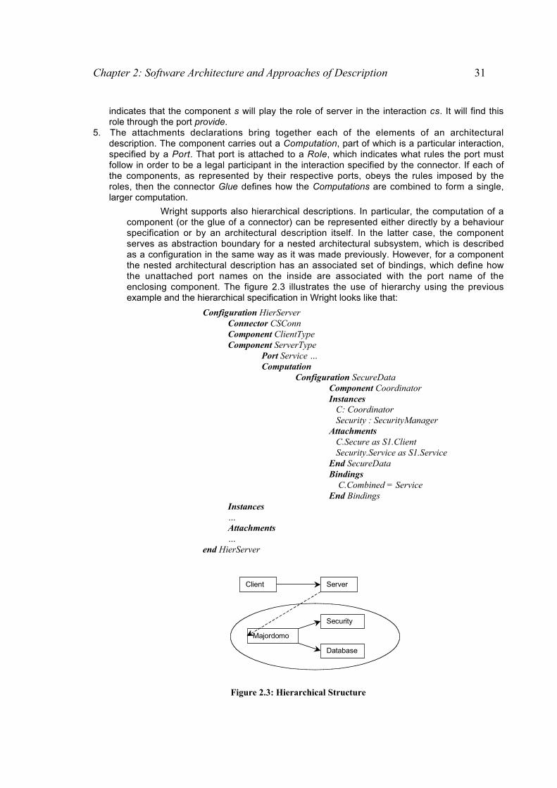
Wright supports also hierarchical descriptions. In particular, the computation of acomponent (or the glue of a connector) can be represented either directly by a behaviourspecification or by an architectural description itself. In the latter case, the componentserves as abstraction boundary for a nested architectural subsystem, which is describedas a configuration in the same way as it was made previously. However, for a componentthe nested architectural description has an associated set of bindings, which define howthe unattached port names on the inside are associated with the port name of theenclosing component. The figure 2.3 illustrates the use of hierarchy using the previousexample and the hierarchical specification in Wright looks like that:
Configuration HierServerConnector CSConnComponent ClientTypeComponent ServerType
Port Service …Computation
Configuration SecureDataComponent CoordinatorInstances C: Coordinator Security : SecurityManagerAttachments C.Secure as S1.Client Security.Service as S1.ServiceEnd SecureDataBindings C.Combined = ServiceEnd Bindings
Instances…Attachments…
end HierServer
Client Server
Majordomo
Security
Database
Figure 2.3: Hierarchical Structure

32 Object Oriented Architectural Description of Frameworks
2.6.2.2 Style
Wright can be used to define architectural styles. A style defines a set properties that areshared by the configurations that are members of the style. These properties can include acommon vocabulary and restrictions on the ways this vocabulary can be used in configurations.
In Wright, common vocabulary is introduced by declaring a set of component andconnector types, using the declaration constructs introduced previously for instance descriptions.
For example, a client-server style would include a declaration of connector type Client.Then when a configuration is declared in the client-server style, Clients are automatically availablefor use.
Interfaces Types: in addition to declaring complete component and connector types, a style’sproperties may constrain only part of a component or a connector. For example, in the pipe-filterstyle all components are filters, which use only dataflow for input and output. This commonality offilters needs to be stated, while the computation itself will differ between different filters. Aninterface type declarations looks like the following one:
Interface Type DataInput = [read data repeatedly, closing the port at or before end-of-data]Interface Type DataOutput = [write data repeteadly, closing the port to signal end-of-data].
Interfaces types can then be used either as the port of a component or as the role of aconnector. In the latter case, the interface represents a constraint on the port interfaces that maybe used in the role.
Parameterization: This ADL allows any part of the description of a type to be replaced with aplaceholder, which is then filled with a parameter when the type is instantiated. So the type of aport or role, a computation, the name of an interface are all parameterizable. For example, in theUnix pipe-filter style, all components have one input, named Stdin, and two outputs, named Stdoutand Stderr. The interface to all Unix filters is the same. But the computation performed by eachUnix filter is different. We can describe the Unix filter as a parameterized component type, asfollows:
Component Unix-filter (C: Computation)Port Stdin = DataInputPort Stdout = DataOutputPort Stderr = DataOutputComputation = C
We can then use this description to describe any number of Unix filters :
Upper : Unix-filter ([pass output, translating to uppercase])Lower: Unix-filter ([pass output, translating to lowercase])LaTex: Unix-filter ([translate input in .tex form to .dvi form; error messages are sent to Stderr])
Another way of parameterizing a type description is by number. Suppose, for example, thata particular class of filter system uses many filters that split their input among a number of outputs.For example,
Component SplitFilter (nout: 1..) Port Input = DataInput Port Output1..nout = DataOutput Computation = [read from Input repeatedly, writing to Output1, Output2 , etc. in succession]
The number parameter can be used to control the number of particular kinds of ports orroles that can appear. A port or role description that can have multiple copies is indicated by

Chapter 2: Software Architecture and Approaches of Description 33
specifying a range of integers as a subscript to its name. In this example, there can be more thanone Output port, depending on the value of the nout parameter.
Constraints: A Wright style description may declare properties that must be obeyed by anyconfiguration in the style. For example, the Wright definition of the pipe-filter style would indicatethat all the connectors must be pipes as follows: ∀ c: Connectors • Type(c) = Pipe.
In addition, the style would require that all components in the system use only DataInputand DataOutput ports:
∀ c: Components; p: Port | p _ Ports(c) • Type(c) = DataInput v Type(c) = DataOutput
Each of the constraints declared by a style represents a predicate that must be satisfied byany configuration declared to be a member of the style. The notation for constraints is based onfirst order predicate logic. The constraints refer to the following sets and operators:
• Components: the set of components in the configuration.• Connectors: the set of connectors in the configuration.• Attachments: the set of attachments in the configuration. Each attachment is
represented as a pair of pairs ((comp, port), (conn,role)).• Name(e) : the name of event e, where e is a component, connector, port, or role.• Type(e): the type of element e.• Ports(e): the set of ports on component e.• Computation(c): the computation of component c.• Roles(c): the set of roles of connector c.• Glue(c): the glue of connector c
In addition, any type has been declared as part of the style’s vocabulary may be referred toby name. As we saw in the example above, the pipe-filter style introduces Pipe, Data Input, andDataOutput, and the constraints of the style refer to these types by name. Let’s see then thecomplete example.
Style Pipe-FilterConnector PipeRole Source [deliver data repeatedly, signalling termination by close]Role Sink [read data repeatedly, closing at or before end of data]Glue [Sink will receive data in same order delivered by Source]
Interface Type DataInput = [read data repeatedly, closing the port at or before end-of-data]Interface Type DataOutput = [write data repeteadly, closing the port to signal end-of-data].Constraints
∀ c: Connectors • Type(c) = Pipe ^∀ c: Components; p: Port | p _ Ports(c) • Type(c) = DataInput v Type(c) = DataOutput
2.6.2.3 Behaviour: Definition of interaction protocols
Each part of a Wright description –port, role, computation and glue- is defined using avariant of CSP [Hoa85]. Each such specification defines a pattern of events (called a process)using operators for sequencing (“_” and “;”), choice (“_” and “_”), and parallel composition (”||”).
Let’s see briefly the main details about CSP• Processes and Events : A process describes an entity that can engage in
communication events. Events may be primitive or they can have associated data as e?xand e!x, representing input and output of data, respectively.
• Prefixing : A process that engages in event e and then becames process P is denotede _ P
• Sequencing : (« sequential composition ») A process that behaves like P until Pterminates (§) and then behaves like Q, is denoted P;Q

34 Object Oriented Architectural Description of Frameworks
• Interrupting : A process that behaves like P until the occurrence of the first event in Q, isdenoted P_ Q.
• Alternative : (« external choice ») A process that can behave like P and Q, where thechoice is made by the environment, is denoted P Q. (« Environment» refers to theother processes that interact with the process.)
• Decision : (« internal choice ») A process that can behave like P or Q, where the choiceis made (non-deterministically) by the process itself, is denoted P _ Q.
• Named Processes : Process names can be associated with a (possibly recursive)process expression. Processes may also be subscripted to represent internal state.
• Parallel Composition : Processes can be composed using the || operator. Parallelprocesses may interact by jointly (synchronously) engaging in events that lie within theintersection of their alphabets. Conversely, if an event e is in the alphabet of processesP1 and P2, then P1 can only engage in the event if P1 can also do so. That is, theprocess P1 || P2 is one whose behavior is permitted by both P1 and P2.
Wright extends CSP in three minor synthatic ways:• it distinguishes between initiating an event and observing an event.• it uses the symbol § to denote the successfully-terminating procces. (In CSP this is
usually written « SKIP »).• It uses a quantification operator: <op> x:S • P(x). This operator constructs a new
process based on the process expresion P(s), and the set S, combining its parts by theoperator <op>. For example, _ i : {1,2,3} • Pi = P1 _ P2 _ P3: i.e., a choice among one ofthree processes, P1, P2, P3. Similarly, .x:S • P(x) is a process that consists of someunspecified sequencing of the processes:
;x:S • P(x) = _ x:S • (P(x); (;x:S\{x} • P(y)).
Thus, we can define the protocols for our example. A simple client role might be definedby the CSP process:
Role Client = (request _ result?x _ Client) _ §
This specification defines a participant in an interaction that repeatedly makes a requestand receives a result, or chooses to terminate successfully.
It is also possible to define interfaces types and to use them in the interaction protocol ofthe role, glue, port and computation. For example,
Interface Type ClientPullT = open _ Operate _ §
where Operate = request _ result?x _ Operate _ close _ §
This spefication defines the behaviour of a participant in an interaction that repeatedlyopens a connection and makes a request and wait for the answer or chooses to terminatesuccessfully.
Interface Type ServerPushT = open _ Operate _ §
where Operate = request _ xresult! _ Operate _ close _ §
This spefication defines the behaviour of a participant in an interaction that waits for theopening of a connection and a request and sends a result or wait for a closing event to terminatesuccessfully
Thus, the specification of the connector is given by the following structure:
Connector C-S-Connector

Chapter 2: Software Architecture and Approaches of Description 35
Role Client = ClientPullTRole Server = ServerPushT
Glue = Client.open _ openServer. _ Glue
_ Client.close _ closeServer. _ Glue
_ Client.request _ requestServer. _ Glue
_ Server.result ?x _ xresultClient !. _ Glue
The connector waits for the occurrence of the events in the client-side (in the first threecases) and notifies the server-side of this ocurrence. In the last case, when the server sends avalue, the client is notified of this event.
This small example intends to be illustrative to understand the notation which will be usedin the rest of this dissertation. A more detailed of the use of CSP notation to define interactionprotocols can be consulted in [All97].
2.6.2.4 Validation of Descriptions
As a formal specification language, Wright has value beyond enabling architects to writedown an architectural description. Another important aspect of the language is its support foranalysis and reasoning about the described system.
Two criteria for an architectural description are consistency and completeness. Informally,consistency means that the description makes sense; that different parts of the description do notcontradict each other. Completeness is the property that a description contains enough informationto perform an analysis; that the description does not omit details necessary to show a certain factor to make a guarantee. Thus, completeness is with respect to a particular analysis or property.
Because the architectural level of design is fundamentally concerned with questions ofstructuring and composition, consistency among parts is especially critical at this level of design.The principles that ensure that a system will function as a coherent entity must be built in as part ofthe overall structure; if the abstract description is inconsistent, any refinement or implementation ofit must necessarily retain that inconsistency.
The problem of completeness is especially critical for the architect because of theimportance of abstraction at this level of design. There is always a tension between the need toinclude critical information that is necessary to guarantee important system properties and the riskof cluttering the architecture with constraints and details that can make the architecture unwieldyand difficult to work with.
To guarantee that an architectural description is both consistent and complete, Wrightprovides a set of tests. We just mention them. More detailed information can be obtained in [All97].In our approach we use this set of tests to verify that the description that we get in our algorithm isvalid exploiting the formal side of Wright ADL
1. Port/Computation Consistency (component)2. Connector Deadlock-Free (connector)3. Roles Deadlock-Free (role)4. Single Initiator (connector)5. Initiator Commits (any process)6. Parameter Substitution (instance)7. Range Check (instance)8. Port-Role Compatibility (attachment)9. Style Constraints (configuration)10. Style Consistency (style)11. Attachment Completeness (configuration)

36 Object Oriented Architectural Description of Frameworks
2.6.2.5 Properties
Having a general overview of how to use Wrigth ADL, let’s see which are the propertiesthat this language according to [MT97]. Thus, this language:
" Formalizes the semantics of architectural connections." Models components components and connectors at a high level of abstraction and do
not assume or prescribe a particular relationship between an architectural descriptionand an implementation. It is referred as implementation independent.
" Provides the specification of component interfaces through the concept of port" Models component semantics allowing the specification of component functionality in
CSP." Express the constraints of the components specifying the protocols of interaction for
each port." Refers to connector interface points as roles." Models connectors as first-class entities." Models connector semantics allowing the specification of connector glue with CSP." Constrains connectors by specifying protocols for each role." Does not facilitate connector subtyping, but supports type conformance, where a role
and its attached port may have behaviorally related, but not necessarily identical,protocols.
" Has the best potential to facilitate understanbility of architectural structure." Does not provide a ‘semantically-sound’ graphical notations." Allows hierarchical composition in principle, but provide no specific constructs to support
it." Has been highlighted as an example of ADL lacking scalability features, yet they have
both been used to specify architectures of large, real world systems.
2.7 Summary
This chapter explains all the features related to software architectures and ADLs focusingon Wright ADL. Thus, we have the vocabulary of the context and tools that we will be used to inferan architectural description of an object oriented frameworks.

Designing software is hard and design of reusable software is even harder. The objectoriented software technology is not the exception in the problem. However the development ofobject oriented framework seems to cope with this trouble in some aspects. In this chapter, weintroduced the concept of object oriented frameworks and their main characteristics. We focus ourwork on two kinds: application and component frameworks.
3.1 Definition
The literature about this field shows a set of possible definitions to characterize an objectoriented framework. However we consider one given in [FSJ00] that defines a framework as areusable design of a system that describes how the system is decomposed into a set of interactingobjects. Sometimes the system is an entire application; sometimes it is just a subsystem. Theframework describes both the component objects and how these objects interact. It describes theinterface of each object and the flow control between them. It describes how the system'sresponsibilities are mapped onto its objects [Joh88, WBJ90]. The most important part of aframework is the way that a system is divided into its components [Deu89]. Frameworks also reuseimplementation, but that is less important than reuse of the internal interfaces of a system and theway that its functions are divided among its components. This high-level design is the mainintellectual content of software, and the frameworks are a way to reuse it.
3.2 Differences with other concepts
The possibility of the frameworks of being used as the base for the development of anumber of applications in the application domain constrasts to the normal way of developing anobject-oriented application. Considering this issue, let’s enumerate briefly which are the differencesof a framework compared to other concepts such as an object oriented design pattern, a patternlanguage and an ordinary object-oriented application. We only keep the concepts that appearduring the development of this dissertation
An object oriented design pattern differs from a framework in three ways [GHJV95]. Firstly,the design patterns are more abstract than a framework since frameworks are embodied in codemeanwhile only the examples of design patterns are coded. The design patterns also describe theintent, trade-offs, and consequences of a design, which is not the case for frameworks. Secondly,design patterns are smaller architectures than frameworks. Thus, a framework can contain anumber of design patterns, but the opposite is never possible. Then the design patterns have nomajor impact of the application’s architecture. Finally, frameworks are more specialized thandesign patterns. Frameworks are always related to a specific application domain, whereas designpatterns are general and can be applied in any application domain.
Pattern languages differ from frameworks in the way that a pattern language describeshow to make a design where an object oriented framework is a design. Pattern languagescomplement a framework since they can teach software engineers how to use a framework, anddescribe why it was designed the way it was. [Mat96]
An object oriented application differs from a framework in that the application describes acomplete executable program that satisfies a requirement specification. The framework captures
CChhaapptteerr 33:: OObbjjeecctt OOrr iieenntteedd FFrraammeewwoorrkkss

38 Object Oriented Architectural Description of Frameworks
the functionality of the application but it is not executable because it does not cover the behaviourin the specific application case.[Mat96]
3.3 Characterization of Frameworks by different dimensions
The most important dimensions to characterize are: the problem domain the frameworkaddresses, the internal structure of the framework and how the framework is intended to be used[Tal94].
Considering the framework domains, they are classified as:• Application frameworks are frameworks that cover functionality that can be applied to
different domains. Examples of application frameworks are frameworks for graphicaluser interfaces [WG94].
• Domain frameworks capture knowledge and expertise in a particular problem domain.Frameworks for manufacturing control [Sch95] and multimedia are examples of domainframeworks.
• Support frameworks are frameworks that offer low-level system services such asdevice drivers [And94] and file access.
Support frameworks are typical cases of fine-grained frameworks, whereas application anddomain frameworks often are monolithic frameworks.
Taking into account the framework structures, if the framework’s internal structure isdescribed it can make it easier to understand the behaviour of the framework. The internalstructure of a framework is related to the concepts of software architectures. In [GS92] a number ofcommon software architectures have been identified. [BMR+96] calls these ‘architecturalframeworks’ since they have been designed in a way that captures the main structure of an object-oriented software architecture: The Layered architectural framework, the Pipes Filters architecturalframework, the Model View Controller architectural framework, the Presentation-Abstraction-Controller architectural framework, the Reflective architectural framework, the Microkernelarchitectural framework, the Blackboard architectural framework and the Broker architecturalframework. We just mentioned them, but in fact we consider them as ‘architectural patterns’ in fine-grained level compared to framework, that can be used integrated in an software architecture.
About the way of use issue, there are two possibilities [Ada95] [FSJ00]:⇒ Architecture driven or inheritance focused frameworks (whitebox frameworks)⇒ Data driven or composition focused frameworks (black box frameworks)
In the case of architecture driven or inheritance focused frameworks, the main approach isto develop applications relying on inheritance and dynamic binding. Framework users make theiradaptation of the framework through:
1. inheriting from framework base classes and2. overriding pre-defined hook methods using patterns like Template Method [GHJV95].
A problem with frameworks that are architecture-driven is that it can be difficult to adaptthem because:
1. it requires application users to have an intimate knowledge of the frameworks’ internalstructure,
2. the framework users have to provide the implementation of the behaviour themselves,which implies a large amount of code to be written.
Thus, they tend to produce systems that are tightly coupled to the specific details of theframework’s inheritance hierarchies.
However in data driven or composition focused frameworks, adapting the frameworks tothe specific needs of the application means relying on object composition and delegation. Existingfunctionality is reused by
1. defining components that conform to a particular interface, and

Chapter 3: Object Oriented Frameworks 39
2. integrating these components into the framework using patterns like Strategy[GHVJ95] and Functor.
How objects can be combined are described by the framework, but what the frameworkdoes depends on what objects the framework user passes into the framework. A framework that isdata-driven is normally easy to use but limiting. They are more difficult to develop since theyrequire frameworks developers to define interfaces and hooks that anticipate a wider range ofpotential use-cases [HJE95]
To handle the problems associated with using inheritance-focused and composition-focused frameworks, a suitable approach can be to provide the framework with an architecture-driven base and a data-driven layer so it is both extendable and easy to use [Tal94]. How theobjects can be combined are described by the framework, but what the framework does depend onwhat objects the framework user posses into the framework. To handle the problems associatedwith using inheritance focused and composition focused frameworks, a suitable approach can beto provide the framework with an architecture-driven base and a data driven layer so it is bothextendable and easy to use.
3.4 Application Frameworks: Specific Features
As our approach is devoted to be applied in application frameworks because we exploreinternal structures, let’s then the main features presented in [FSJ00] that we intend to represent inan architectural description.
Each object in the framework is described by an abstract class. An abstract class is a classwith no instances, so it is used only as a superclass [WBJ90]. An abstract class usually has atleast one unimplemented operation deferred to its subclasses. Since an abstract class has noinstances, it is used as a template for creating subclasses rather than as a template for creatingobjects. Frameworks use them as design of their components because they both define theinterface of the components and provide a skeleton that can be extended to implement thecomponents.
In addition to providing an interface, an abstract class provides part of the implementationof its subclasses. For example, a template method defines the skeleton of an algorithm in anabstract class, deferring some of the steps to subclasses [GHJV95]. Each step is defined as aseparate method that can be redefined by a subclass, so a subclass can redefine individual stepsof the algorithm without changing its structure. The abstract class can either leave the individualsteps unimplemented (in other words, they are abstract methods) or provide a defaultimplementation (in other words, they are hook methods) [Pre95]. A concrete class must implementall the abstract methods of its abstract superclass and may implement any of the hook methods. Itwill then be able to use all the methods it inherits from its abstract superclass.
Frameworks take advantage of all three of the distinguishing characteristics of objectoriented programming languages: data abstraction, polymorphism, and inheritance. Like anabstract data type, an abstract class represents an interface behind which implementation canchange. Polymorphism is the ability for a single variable or procedure parameter to take on valuesof several types. Object-oriented polymorphism lets a developer mix and match components, letsan object change its collaborators at runtime, and makes it possible to build generic objects thatcan work with a range of components. Inheritance makes it easy to make a new component. aframework describes the architecture of an object-oriented system; the kinds of objects in it, andhow they interact. It describes how a particular kind of program, such as a user interface ornetwork communication software is decomposed into objects. It is represented by a set of classes(usually abstract), one for each kind of object, but the interaction patterns between objects are justas much a part of framework as the classes.
The first widely used framework, developed in the late 1970s, was the Smalltalk-80 userinterface framework called Model/View/Control (MVC) [Gol84, KP88, LP91]. MVC showed thatobject-oriented programming was well suited for implementing graphical user interfaces (GUIs). Itdivides a user interface into three kinds of components: models, views, and controllers. These
40 Object Oriented Architectural Description of Frameworks
objects work in trios consisting of a view and a controller interacting with a model. A model is anapplication object and is supposed to be independent of the user interface. A view manages aregion of the display and keeps it consistent with the state of the model. A controller converts userevents (mouse movements and key presses) into operations on its model and view. For example,controllers implement scrolling and menus. Views can be nested to form complex user interfaces.Nested views are called subviews.
The important classes in the framework, such as Model, View, and Controller of MVC, areusually abstract. Like MVC, a framework usually comes with a component library that containsconcrete subclasses of the classes in the framework. Although a good component library is crucialcompanion to a framework, the essence of a framework is not the component library, but the modelof interaction and control flow among its objects.
3.5 Components and Frameworks
Considering white-box frameworks, we said that adapting them can be very difficultbecause one has to understand what each element in the structure means and how the elementswork together in order to reuse the structure. The complexity of adaptation of course depends onthe complexity of structure to be adapted. Moreover, putting several complex structures togetherto form a bigger system (e.g. merging together groups of statements or different class hierarchies)is also difficult. Thus, [MN95] proposes the use of the software component to solve this problem.
A component is an abstraction of a software structure that may be used to build biggersystems, while hiding the implementation details of the smaller structures. Putting togethercomponents is simple, since each component has a limited set of ‘plugs’ with fixed rules specifyinghow it may be linked with other componens. Instead of having to adapt the structures of a piece ofsoftware to modify its functionality, a user plugs the desired behaviour into the parameters of thecomponent.
There are two important aspects to components:• Encapsulation of software structure as abstract components.• Composition of components by binding their parameters to specific values, or other
components.Encapsulation is the means to achieve variability, since the possible variation is expressed
in the parameters (or ‘plugs’) of the component. Adaptability is achieved during composition, sincea software structure composed from components can be more easily reconfigured than anunencapsulated structure.
The open variability of white-box structures can be changed for the fixed variability ofpossible connections to the plugs of the component. This restriction of variability is possible due tothe fixed intented purpose of the component; it also includes the possibility to check thecorrectness of combinations of parameters. This is called ‘closed’ or ‘black-box’ software reuse.
What are the differences between objects and components? First of all, objectsencapsulate services, whereas components are abstractions that can be used to construct object-oriented systems. Objects have identity, state and behaviour, and are always run-time entities.Components, on the other hand, are generally static entities that are needed at system build-time.They do not necessarily exist at run-time. Components may be of finer or coarser granularity thanobjects: e.g. classes, templates, mix-ins, modules. Components should have an explicitcomposition interface, which is type-checkeable. An object can be seen as a special kind ofstateful component that is available at run-time.
A piece of software can be called a component if it has been designed to be composedwith other components. In general this is done to address a particular class of applications. If thatis the case, we say a component framework has been developed for that application area.
A component framework does not just consist of a library of components, but must alsodefine a generic architecture for a class of applications. A component framework is a collection ofsoftware artefacts that encapsulated domain knowledge, requirements models, a generic softwarearchitecture and a collection of software components addressing a particular application domain.Thus, we have
Chapter 3: Object Oriented Frameworks 41
• Flexibility in a framework that is achieved through variability in the components andadaptability in the architecture.
• Flexibility in an application that is promoted by making the specific architecture explicitand manipulable.
Development of specific applications is framework-driven, in the sense that all phases ofthe software lifecycle, including requirements collection and specification are determined accordingto set patterns formalized within the framework. To a large extent, system design is already done,since the domain and system concepts are specified in the generic architecture. The remaining artis to map the specific requirements to the concepts and components provided by the framework.
[MN95] proposes a scenario where they assume that all parts of the component frameworkare formally specified, and managed by an application development environment. The environmentguides the requirements collection and specification activities, and helps to guide the specializationand configuration of the application from available components.
Given this scenario of component-oriented development, software composition is definedas the systematic construction of software applications from components that implementabstractions pertaining to a particular problem domain. Composition is systematic in that it issupported by a framework, and in the sense that components are designed to be composed.
3.6 Keys of Frameworks
3.6.1 : Analysis, Design and Code Reuse
As it is inferred from the definition and the features described so far, the analysis, designand code reuse is one of the keys of the frameworks. Let’s enumerate the reasons given in[FSJ00].
A framework reuses code because it makes it easy to build an application from a library ofexisting components. These components can be easily used with each other because they all usethe interfaces of the framework. A framework also reuses code because a new component caninherit most of its implementation from an abstract superclass. But reuse is best when you don'thave to understand the component you are reusing, and inheritance requires a deeperunderstanding of a class that is using it as a component, so it is better to reuse existingcomponents than to make a new one. Of course, the main reason a framework enables code reuseis that it is a reusable design. It provides reusable abstract design abstract algorithms and a high-level design that decomposes a large system into smaller components and describes the internalinterfaces between components. These standard interfaces make it possible to mix and matchcomponents and to build a wide variety of systems from a small number of existing components.New components that meet these interfaces will fit into the framework, so component designersalso reuse the design of a framework. Finally a framework reuses analysis. It describes the kindsof objects that are important and provides a vocabulary for talking about a problem. An expert in aparticular framework sees the world in terms of a framework and will naturally divide it into thesame components. Two expert users of the same framework will find it easier to understand eachother's designs, since they will come up with similar components and will describe the systemsthey want to build in similar ways.
Analysis, design and code reuse are all important, though in the long run it is probably theanalysis and design reuse that provide the biggest payoff [BR96].
3.6.2 Hotspots and Frozen Spots
The functions in the framework design that need to be customised to change thebehaviour of the framework are called “hotspots”. Providing a new implementation for such afunction makes it possible to add variation to the applications that are based upon the framework.The other functions in the framework are called frozen spots. They represent the static parts of the
42 Object Oriented Architectural Description of Frameworks
framework. These functions define the flow control in the application. They will call the hotspots atthe right time.
The template and concrete methods are frozen spots, while the abstract methods arehotspots. The behaviour of template method is inherited by the subclasses of the frameworkclasses. These methods will call at least one template or abstract method that is implemented inthe same class or in another class of the framework. The framework developer encodes some ofhis domain knowledge in the template methods. He knows which steps must be taken to performone of the framework responsibilities and he transmits this knowledge by calling other methods(abstract as well as concrete) in the template method.
3.7 Analysis: Goals, Benefits and Weaknesses
According to the definition given previously, a framework can be seen as a set ofcooperating classes that comprises a reusable foundation for a specific application domain. In thissection we enumerate the general features about frameworks considering goals, benefits andweakenesses [FSJ00, Mat96]
3.7.1 Goals
Within the main goals of a framework, we consider the frameworks firstly must minimizethe amount of code needed to implement similar applications, since the common abstractions forthe applications are captured in the framework, which reduces the fraction of new code to bedeveloped.
Finally, they must optimize generality and leverage. The framework users have to tailor theframework to the applications’s specific needs, for example, through subclassing. For leverage, it isnecessary that the frameworks include a set of predefined subclasses that the framework user canuse at once. Thus if the framework is too general, it will not support the framework user and, if it isnot general, it will be useable in very few situations.
3.7.2 Benefits
Talking about benefits, we can mention that the frameworks provide a real decrease inlines of code that have to be developed if the application’s required functionality and thefunctionality captured by the framework are similar to a high degree.
Secondly, an important aspect is that the framework's code is already written anddebugged.
Another aspect is that the frameworks offer reuse of design not only code. Frameworkreusability leverages the domain knowledge and prior effort of experienced developers in order toavoid re-creating and re-validating common solutions to recurring application requirements andsoftware design challenges.
The frameworks also enhance modularity by encapsulating volatile implementation detailsbehind stable interfaces. Framework modularity helps improve software quality by localizing theimpact of design and implementation changes
Another benefit is that the extensibility of the frameworks is provided by explicit hookmethods [Pre95] that allow applications to extend its stable interfaces. Hook methodssystematically decouple the stable interfaces and behaviors of an application domain from thevariations required by instantiations of an application in a particular context. Frameworkextensibility is essential to ensure timely customization of new application services and features.
One of the critical benefits is the run-time architecture of a framework is characterized byan “inversion of control.'' This architecture enables canonical application processing steps to becustomized by event handler objects that are invoked via the framework's reactive dispatching
Chapter 3: Object Oriented Frameworks 43
mechanism. When events occur, the framework's dispatcher reacts by invoking hook methods onpre-registered handler objects, which perform application-specific processing on the events.Inversion of control allows the framework (rather than each application) to determine which set ofapplication-specific methods to invoke in response to external events (such as window messagesarriving from end-users or packets arriving on communication ports).
The improved maintenance is another benefit because when an error is corrected in theframework, the same error in software derived from the framework is corrected.
3.7.3 Weaknesses
Taking into account weaknesses, we can say that it is difficult to develop a goodframework. Experience in the application domain is necessary when building the framework.
One critical aspect is the documentation of the frameworks because if the frameworks arenot supported by the necessary user documentation, they are not likely to be used.
The backward compatibility can be difficult to maintain, since the frameworks evolve andbecome more mature over time and the applications built on the frameworks must evolve with it.
The debugging process can be complicated because it is difficult to distinguish bugs in theframework from bugs in the application code. If the bugs are in the framework, it can be impossiblefor the framework user to fix the bug.
Thus it is possible to conclude that the generality and the flexibility of the framework maywork against its efficiency in a particular application.
3.8 Summary
This chapter summarizes the main features about object oriented frameworks, and thus,we give the context where we apply the Wright ADL and architectural patterns as complementarytechniques to infer an architectural description.

44 Object Oriented Architectural Description of Frameworks
The terms software architecture and object oriented framework have in common the lack ofconsensus in their definition. Thus, we presented the most known definitions in the two previouschapters, and we took those that summarizes the main features of both concepts. In case ofsoftware architecture, we use the classical definition given in [SG96] that defines the softwarearchitecture as the structure of the components of a program/system, their interrelationships, andprinciples and guidelines governing their design and evolution over time. About the definition ofobject oriented framework, we consider the definition given in [FSJ00] that defines a framework asa reusable design of a system that describes how the system is decomposed into a set ofinteracting objects. The framework describes both the component objects and how these objectsinteract. It describes the interface of each object and the flow control between them. It describeshow the system's responsibilities are mapped onto its objects.
The most remarkable thing is that both terms seems to be applied in non-intersectingcontexts. Only the work proposed by [SG99] shows an approximation of getting an architecturaldescription of frameworks using Wright ADL to represent Sun JavaBeans components. Thus, asour focus is to define a mapping from object oriented frameworks to a software architecture, wemust analyze previously which the problems are possible to find and answer them to give a contextto our work. This chapter presents some important issues and decisions made during the study ofthe software architectures and their applicability in object oriented frameworks.
4.1 Software Architecture: Level of Abstraction
As we described in chapter 2, a software architecture is a bridge between domainknowledge, functional and non-functional application requirements, and the design of anapplication. A stable software architecture need to retain the concepts and structures from theapplication domain [Ber98]. On the other hand, successful software architectures often require the‘invention’ or discovering of a main mechanism or structure that captures the essence of anapplication and its solution domains. As such the process of defining a software architectureinvolves understanding and structuring of domain knowledge, in combination with the creativeprocess of inventing a conceptual model of the application’s essence.
An architecture is based on a choice of components and connectors. Componentsrepresent a system’s main computational elements and data stores: clients, servers, filters,databases, etc. Connections between thses elements range from the simple and generic (e.g.procedure call, pipes, shared data access) to the complex and domain-specific (e.g. implicitinvocation mechanisms, client-server protocols, database protocols). [AG96] This choicefundamentally determines what the structure will be and what this structure tells us about thesystem. [Neb98]
There are many valid notions of software architecture that exist at different levels ofabstraction. [AG96] says that an architectural description makes a complex system intellectuallytractable by characterizing it at a high-level of abstraction. In particular, the architectural designexposes the top-level design decisions and permits a designer to reason about satisfaction ofsystem requirements in terms of assignment of functionality to design elements. The high-level ofabstraction is the trend in all the actual literature about software architecture. But in fact thebuilding of an architectural description is a conceptual modeling [Neb98]. A concept is
CChhaapptteerr 44:: AArrcchhii tteeccttuurraa ll DDeessccrr iipptt iioonn ooffFFrraammeewwoorrkkss :: FF ii rrss tt PPrroobblleemmss

46 Object Oriented Architectural Description of Frameworks
characterized by its denomination/designation (the names under which the concept is known), itsextension (the phenomena described by the concept), and its intention (the set of propertiesdefining the concept). By relating the extension and the intension of an architectural concept weproduce new information about the considered software. This is what is commonly known as“moving to another abstraction level”.
Based on this idea, we restrict the use of the term architecture to the semantic structure ofan application, a static notion of software architecture, and we consider that what is important is tounderstand how the classes in a framework are related structurally and what the consequences ofthis structure are on the software system. We focus our work on a lowest or base-level notion ofsoftware architecture that reflects the semantic structure of a software system: the code-levelcombined with information about design-level in object oriented frameworks. We also adopt a morerestrictive definition of architecture as the static instance structure, i.e. the instance structure thatis always present during execution and thus characterizes all run-time configuration of instances.Furthermore, the architecture determines which configurations are reachable during execution.
This dissertation has as a main goal the definition of a bridge between the informal natureof the design and implementation process and the formalism required from an architecturaldescription. The proposal works with Wright ADL as the formal language and also the architecturalpatterns as a complement.
4.2 Architectural Description: Conceptual Model
The previous section gaves us the definition and the level of abstraction that we adopt.Based on these concepts, the objective of this dissertation is searching a conceptual model of theclasses of the object oriented frameworks, composed of architectural components and connectors,and that represents the semantic structure of an application. We call this model the architecturaldescription of an object oriented framework. Let’s see then the main features of the approach andwhich the level of abstraction is located in.
Some ideas of this dissertation are based in the proposal made by [Now99]. In this work,he proposes the conceptual modelling perspective on software architecture presented in the figure4.1. The software domain is the reference system (left side of the illustration). The model system(right side of the illustration) is the architectural model which explicitly describes the phenomenaand concepts in the software domain from an architectural perspective. During softwareconstruction and evolution we form concepts by classification (top left) over the software domain.Examples include design patterns [GHVJ95], architectural patterns [BMR+96], components[Szy98], connectors [SG96] and architectural styles [SG96].

Chapter 4: O. O. Architectural Description of Framework: First Problems 47
Modeling
Interpreting
Model System
Architecture Representation
Architectural Descriptions
Referent System
Architectural Concepts
Software Domain
Abstraction Specification
Figure 4.1: Conceptual Modelling of Software Architectures [Now99]
Architectural models seeks to describe such concepts in a rigorous way (top right). Thedescriptions specify representations of architectural phenomena (bottom right), that facilitate theinterpretation and understanding of the software domain (bottom-left). But the main problem is thatthe architectural model is “lost” in the process of modelling an object oriented application(architectural concepts-architectural description in dotted line in figure 4.1) because it is expressedusing informal, diagrammatic notations (such as box-line diagrams) and idiomatic characterizations(such as client-server organization, layered system, or blackboard architecture). The meanings ofsuch diagrams and phrases by informal convention are understood only by a small set ofdevelopers. This relative informality leads to architectural designs that are inherently ambiguous,difficult to analyze, hard to mechanize.
The objective of “building the bridge” between informal and formal approaches is thedefinition of a mapping that allows to get an architectural description as an interaction architecture.The concept of interaction architecture is proposed in [Now99]. We want to have the followingelements (these are a restricted definition compared to the presented ones in [Now99]):
⇒ A component instance models a set of collaborating objects providing an interface and abehaviour at execution time. The interface is considered as the service interface and itconsists of a set of ports: input ports through signals/information are sent into thecomponent instance and hence affect its behavior; output ports wheresignals/information are sent out from the component instance as well as affecting othercomponent instances.
⇒ A component class is a description of a number of similar component instances, and itmodels a set of object classes describing objects existing before runtime. The objectsimplement the component instance as described above.
⇒ An interaction instance models either the creation of an object, the deletion of an object,or the communication of a signal or information between two component instances atruntime. An interaction instance has a role interface consisting of a set of componentroles. When connecting interaction instances with component instances we mapcomponents to roles. The roles are qualified by a set of required ports.
⇒ An interaction class is a description of a number of interaction instances with the samecomponent interfaces.
The developed algorithms and the mapping are focused on the definition of componentclasses and interaction classes mapping from classes in an object oriented framework. Thecomponent instances and interaction instances are obtained when the topological configuration isdefined using in Wright ADL.

48 Object Oriented Architectural Description of Frameworks
4.3 Architectural Components = Software Components ?
Having decided the level of abstraction of the software architectures where we work andhow the architectural elements (components and connectors) will be, two questions should beanswered: can we define a direct mapping from software components to architecturalcomponents? can the classes in an object oriented framework be considered as softwarecomponents?. In spite that the relationship between class-object and architectural componentappeared in the previous section, and it seems to let us define the direct mapping that we aresearching, this section intends to answer these questions and give more elements to work in thecontext.
Firstly, let’s see the concept of software component. [Szy98] summarizes all the definitionin the literature considering that a software component:
⇒ is a unit of composition and an encapsulated part of a software system⇒ has contractually specified interface⇒ has context dependencies only⇒ serves as the building block for a structure of a system.
To clarify the concepts, [MN95] explains that the interface of a component defines thecomponent’s access points and the access to the services provided by the component. As thecomponent and its clients are developed in mutual ignorance, it is the contract that forms acommon ground for successful interaction. The definition requires specification of what thedeployment environment will need to provide, such that the components can function. These needsare called context dependencies, referring to the context of composition and deployment. Acomponent’s specification of context dependencies must include its required interface and thecomponent world (or worlds) that it has been prepared for. Based on the features given previously,[PW92] proposes two possible categorizations of components:
• Processing elements: supply transformations of the data elements that contain theinformation that is transformed.
• Data elements• Connecting elements: which at any time may be either processing elements, data
elements or both- constitute the 'glue' that holds the different pieces together.Another categorization of components developed for the object-oriented programming
paradigm is as follows [BMR+96]:• Controller components• Coordinator components• Interface components• Service provider components• Information holder components• Structuring components.
So far, we have obtained the main features of a software components and a two possiblecategorization of them. Let’s see now the definition of object. [Mat00b] defines that an object canbe viewed as a unit that holds a cohesive piece of information and that defines a collection ofoperations (implemented by methods) to manipulate it. Meanwhile, [MKMG96] says that an objectoriented design allows system designers to encapsulate data and behaviour in discrete objects thatprovide explicit interfaces to other objects. They can therefore hide the fact that they mightencapsulate existing programs, act as proxies for remote resources, or even coordinate multiple,concurrent requests [MN95].
Specifically, at a programming language level, components may be represented as classesobjects or a set of them, because the requirements to be a software component (encapsulatedinformation, specified interface, context dependencies and serve as a building block) are fulfilled byan object according to the definition given previously. Thus, we can provide a direct mappingbetween a software component (in our case classes) and an architectural component (component
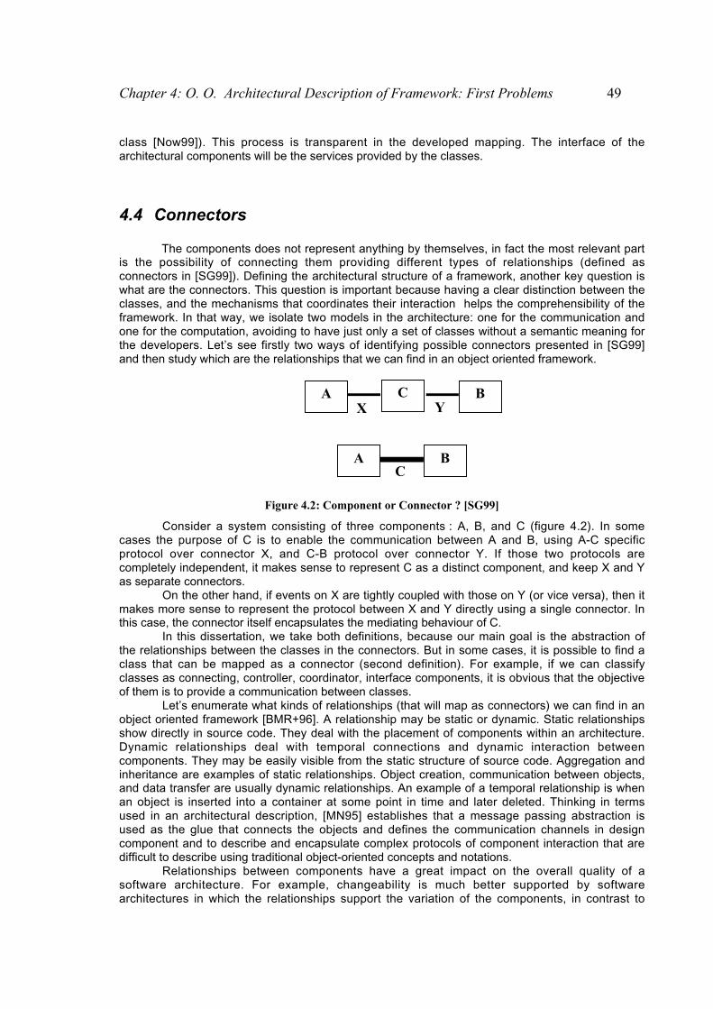
Chapter 4: O. O. Architectural Description of Framework: First Problems 49
class [Now99]). This process is transparent in the developed mapping. The interface of thearchitectural components will be the services provided by the classes.
4.4 Connectors
The components does not represent anything by themselves, in fact the most relevant partis the possibility of connecting them providing different types of relationships (defined asconnectors in [SG99]). Defining the architectural structure of a framework, another key question iswhat are the connectors. This question is important because having a clear distinction between theclasses, and the mechanisms that coordinates their interaction helps the comprehensibility of theframework. In that way, we isolate two models in the architecture: one for the communication andone for the computation, avoiding to have just only a set of classes without a semantic meaning forthe developers. Let’s see firstly two ways of identifying possible connectors presented in [SG99]and then study which are the relationships that we can find in an object oriented framework.
Y X
C
A B C
A B
Figure 4.2: Component or Connector ? [SG99]
Consider a system consisting of three components : A, B, and C (figure 4.2). In somecases the purpose of C is to enable the communication between A and B, using A-C specificprotocol over connector X, and C-B protocol over connector Y. If those two protocols arecompletely independent, it makes sense to represent C as a distinct component, and keep X and Yas separate connectors.
On the other hand, if events on X are tightly coupled with those on Y (or vice versa), then itmakes more sense to represent the protocol between X and Y directly using a single connector. Inthis case, the connector itself encapsulates the mediating behaviour of C.
In this dissertation, we take both definitions, because our main goal is the abstraction ofthe relationships between the classes in the connectors. But in some cases, it is possible to find aclass that can be mapped as a connector (second definition). For example, if we can classifyclasses as connecting, controller, coordinator, interface components, it is obvious that the objectiveof them is to provide a communication between classes.
Let’s enumerate what kinds of relationships (that will map as connectors) we can find in anobject oriented framework [BMR+96]. A relationship may be static or dynamic. Static relationshipsshow directly in source code. They deal with the placement of components within an architecture.Dynamic relationships deal with temporal connections and dynamic interaction betweencomponents. They may be easily visible from the static structure of source code. Aggregation andinheritance are examples of static relationships. Object creation, communication between objects,and data transfer are usually dynamic relationships. An example of a temporal relationship is whenan object is inserted into a container at some point in time and later deleted. Thinking in termsused in an architectural description, [MN95] establishes that a message passing abstraction isused as the glue that connects the objects and defines the communication channels in designcomponent and to describe and encapsulate complex protocols of component interaction that aredifficult to describe using traditional object-oriented concepts and notations.
Relationships between components have a great impact on the overall quality of asoftware architecture. For example, changeability is much better supported by softwarearchitectures in which the relationships support the variation of the components, in contrast to
50 Object Oriented Architectural Description of Frameworks
architectures in which any change to a component affects the implementation of its clients andcollaborators.
4.5 Internal State of the Components
The most remarkable problem using the Wright ADL is the lack of having internal state of acomponent. In fact, this ADL is focused on the interaction behaviour and there is no possibility touse the operations given by the components. Most of the executions are hidden behind the non-deterministic choices in the specification. Thus, it is not possible to have any specification aboutthe functional aspects of the components. [San97] proposes the use of Abstract Machines B tosolve this problem. Let’s see how this mechanism works and how it can be applied in a descriptionmade with Wright ADL.
4.5.1 Wright and Abstract Machines B
Wright ADL is focused on the behavior of the interaction and the components themselvesare not considered. It is not possible to use the operations which are offered by the components.All the executions specific to the components are hidden in the non-deterministic choices and nospecification of the functional aspects of the component is given. It is seems interesting to have anspecification of the module itself combining Wright with this vision of the module.
To describe a module, the method B [Abr96] is an adequate solution because it allows achecking of the description of the abstract machines and it is able automatically to generate C orAda code. Details about how the method B works can be found in [Abr96]. But to have an idea of aspecification of B, we present the specification of Text_Filter.
An abstract machine B (figure 4.3) has an internal state represented by declarations ofvariables (line andword for Text_Filter). These variables can be initialized during the first use of theabstract machine. We can declare invariants which must be checked by all the operations.
An abstract machine B provides operations and can import another abstract machine B .Text_Filter has and imports operations to do some tests (IsLetter, IsDigit) or to modify its internalstate (BuildWord, IncrementLine). These are the operations that the abstract machine B has andthey will be used in this specification.
Knowing how to describe the behavior and the interaction of the components using Wrightand the components using the formal specification B, let’s see how to join these two conceptsrespecting their philosophy and their constraints. The idea is to use the method B to describe thecomponents in order to emphasize the internal executions of the components masked in non-deterministic choices.

Chapter 4: O. O. Architectural Description of Framework: First Problems 51
MACHINE Text INCLUDES BASIC_STRING PROMOTES IsLetter, IsDigit, IsSeparator, StrComp, Concat, Small VARIABLES line word INVARIANTS line å NAT1
word å Word INITIALISATION line:=1; word:=empty OPERATIONS bb <-- IsEmptyWord = bb:= (StrComp(word, empty)) ; BuildWord(cc) = PRE cc å Letter THEN word:= Concat(word, cc) END ; IncrementLine = PRE line +1 å NAT1 THEN line:= line+1 END ; ww, ii <-- Data = ww, ii, word:= Small(word), line, empty END
Figure 4.3: Specification in B of Text_Filter
4.5.2 Interaction of the Abstract Machine B with the environment
The first problem relates to how we express the interaction of the abstract machine B withits environment and then, the connection with the Wright component. Taking into account that aWright component interacts with his environment by ports, we decide to make the same thing forthe abstract machine B by defining a special port called Port B. On the level of the Wrightcomponent , we define also a special port called Port Component, which will be used for theinteraction with this abstract machine B (Figure 4.4).
Port B
Port Component
Component Wright
Abstract Machine
B
Figure 4.4: Ports Component and B
As the concept of port is not specific to the method B, it is necessary to create an interfacewhich makes the bridge feasible between these two concepts. We can see an abstract machine Bas a black box with buttons (operations) which carry out the desired operation pressing them.From this vision of an abstract machine two observations can be considered:
• the interface must contain all the operations offered by the abstract machine B.• It is necessary to use the deterministic choice of CSP to specify these different
operations since the choice of the operation does not depend on the machine but on theenvironment.
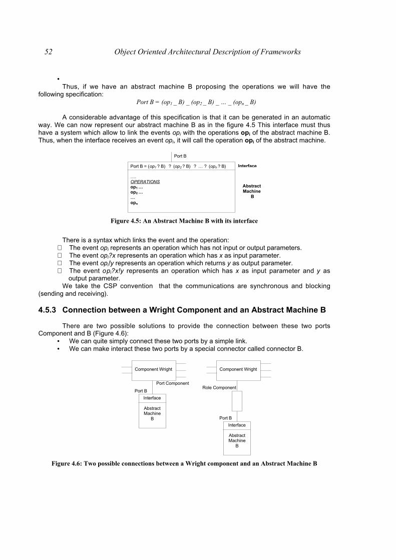
52 Object Oriented Architectural Description of Frameworks
• Thus, if we have an abstract machine B proposing the operations we will have the
following specification:Port B = (op1 _ B) _ (op2 _ B) _ … _ (opn _ B)
A considerable advantage of this specification is that it can be generated in an automaticway. We can now represent our abstract machine B as in the figure 4.5 This interface must thushave a system which allow to link the events opi with the operations opi of the abstract machine B.Thus, when the interface receives an event opi, it will call the operation opi of the abstract machine.
Port B
Port B = (op1 ? B) ? (op2 ? B) ? … ? (opn ? B) …. OPERATIONS op1 … op2 … … opn
Interface
Abstract Machine
B
Figure 4.5: An Abstract Machine B with its interface
There is a syntax which links the event and the operation:⇒ The event opi represents an operation which has not input or output parameters.⇒ The event opi?x represents an operation which has x as input parameter.⇒ The event opi!y represents an operation which returns y as output parameter.⇒ The event opi?x!y represents an operation which has x as input parameter and y as
output parameter.We take the CSP convention that the communications are synchronous and blocking
(sending and receiving).
4.5.3 Connection between a Wright Component and an Abstract Machine B
There are two possible solutions to provide the connection between these two portsComponent and B (Figure 4.6):
• We can quite simply connect these two ports by a simple link.• We can make interact these two ports by a special connector called connector B.
Role Component Port B
Port Component
Component Wright
Interface
Abstract Machine
B Port B
Component Wright
Interface
Abstract Machine
B
Figure 4.6: Two possible connections between a Wright component and an Abstract Machine B

Chapter 4: O. O. Architectural Description of Framework: First Problems 53
The second solution is better in this context because:• The interaction between the Wright component and the abstract machine B requires
specifications more complex than those described in the port B.• By using a connector, we can describe this interaction rigorously while remaining
coherent with the Wright component because the specification of Calculation will onlydescribe the interaction of the different ports.
• The use of a connector has the advantage of playing the role of glue between these twoconcepts of Wright component and abstract machine B. Moreover, this connector makespossible to keep a rather strong independence between these two different concepts.
4.5.4 Description of the interaction between a Wright component and anAbstract Machine B
The goal is to emphasize the internal executions of the component which are masked innon-deterministic choices in the Wright specification . Being specified these executions in theabstract machine B, it is enough to use the port B to reveal them in the Wright specification. Let’ssee how this is done in the example of the Text_Filter component.
Example: The component Text_Filter receives a set of characters. If the character that read is:• One letter or one number, it adds the character to the word that is building, and it reads the nextcharacter• The special character B, It increments the line counter and it reads the next character• One separator , if the previous character was not one separator or this separator is not the firstcharacter, it writes the word in small letters and it sends the pair (word, line number) and it reads thenext character.
When the component has finished analyzing the set of characters, it sends the last pair and it stops.
Component Text_FilterPort Input = DataInputPort Output = DataOutputComputation =
readInput. _ (( Input.data ?c _ (Computation
_ ),(!. iwwriteOutput _ Computation )))
_ (Input.end_of_data _ closeInput. _ (( closeOutput. _ §)
_ ( ),(!. iwwriteOutput _ closeOutput. _ § ))))
Based on this informal specification, it is possible to describe the internal behavior which ismasked in the non-deterministic choices. To do that, we use the ports Component and B as well asthe connector B. In the connector B we reveal the description of the internal behavior of thecomponent.
On the level of the Wright component, we must describe the interaction between thiscomponent Wright and the connector B. This interaction is at the level of the non-deterministicchoices:
• In the first non-deterministic choice, where a character is read (Input.data?c), the internalbehavior depends on the read character. Thus we have the new specification:
Input.data ?c _ cwriteComponent !. _
((Component.continue _ Computation)
_(Component.Data ?(w,i) _ ),(!. iwwriteOutput _ Computation ))
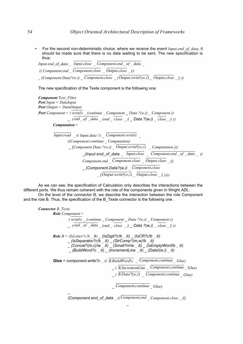
54 Object Oriented Architectural Description of Frameworks
• For the second non-deterministic choice, where we receive the event Input.end_of_data, itshould be made sure that there is no data waiting to be sent. The new specification isthus:
Input.end_of_data _ closeInput. _ dataofendComponent __. _
(( Component.end _ closeComponent. _ closeOutput. _ §)
_ (Component.Data?(w,i) _ closeComponent. _ ( ),(!. iwwriteOutput _ closeOutput. _ § ))
The new specification of the Texte component is the following one:
Component Text_FilterPort Input = DataInputPort Output = DataOutput
Port Component = ( cwrite! _ (continue _ Component _ Data ?(w,i) _ Component ))
_ ( dataofend __ _ (end _ close _ § _ Data ?(w,i) _ close _ § ))
Computation =
readInput. _ (( Input.data ?c _ cwriteComponent !. _
((Component.continue _ Computation)
_ (Component.Data ?(w,i) _ ),(!. iwwriteOutput _ Computation )))
_(Input.end_of_data _ closeInput. _ dataofendComponent __. _ ((
Component.end _ closeComponent. _ closeOutput. _ §)
_ (Component.Data?(w,i) _ closeComponent.
_ ( ),(!. iwwriteOutput _ closeOutput. _ § ))))
As we can see, the specification of Calculation only describes the interactions between thedifferent ports. We thus remain coherent with the role of the components given in Wright ADL.
On the level of the connector B, we describe the interaction between the role Componentand the role B. Thus, the specification of the B_Texte connector is the following one .
Connector B_TexteRole Component =
( cwrite! _ (continue _ Component _ Data ?(w,i) _ Component ))
_ ( dataofend __ _ (end _ close _ § _ Data ?(w,i) _ close _ § ))
Role B = (IsLetter?c!b _ B) _ (IsDigit?c!b _ B) _ (IsCR?c!b _ B)_ (IsSeparator?c!b _ B) _ (StrComp?(m,w)!b _ B)_ (Concat?(m,c)!w _ B) _ (Small?m!w _ B) _ (IsEmptyWord!b _ B) _ (BuildWord?c _ B) _ (IncrementLine _ B) _ (Data!(w,i) _ B)
Glue = component.write?c _ (( cBuildWordB !. _ continueComponent. _ Glue)
_ ( ineIncrementLB. _ continueComponent. _ Glue)
_ ( ),?(. iwDataB _ continueComponent. _ Glue)
_ continueComponent. _ Glue)
_
(Component.end_of_data _ (( endComponent. _ Component.close _ §)
_

Chapter 4: O. O. Architectural Description of Framework: First Problems 55
( ),?(. iwDataB _ ),(!. iwDataComponent
_ Component.close _ §)))
In this specification of the connector B, we see the description of the internal behavior ofthe component using the events of the role B. However, it is important to note that our specialconnector B is not completely a Wright connector . The connector B_Texte makes internal choiceswhich are represented by non-deterministic meanwhile a Wright component can not make internalchoices and only describes the interaction between different components. However, this is notincoherent with the idea of connector in our case. Starting we know that the special connector Bdid not have same specificity comparing Wright connectors. There are two reasons:
• A Wright connector can have different styles of interactions: connector pipe-filter, client-server, whereas the purpose of our special connector B is precisely to describe only oneinteraction: internal behavior of the component.
• The purpose of a Wright connector is only to describe the interaction between variouscomponents. The connector B does not aim to connect various components but rather todescribe the interaction between the Wright component and its abstract machine Bwhich represents in fact one component.
4.5.4.1 Resolution of non-determinism in the connector B
The non-determinism of the Wright component which is in the connector B_Text can besolved. Thanks to the abstract specification of the component Text_Filter, we know to clarify thesenon-deterministic choices. In our case, the non-deterministic choices correspond to tests of the if-then-else type. In the figure , a little abstract specification of this resolution of the non-deterministicchoices is given. There is a notation in CSP to express the test of the if-then-else [Hoa85 ]: theprocess P < |b| > Q behaves as the process P if the Boolean expression B is true and like theprocess Q if not.
Thus we can describe in a formal way the connector B_Texte specified in an abstract way.Connector B_Texte
Role Component = ( cwrite! _ (continue _ Component _ Data ?(w,i) _ Component ))
_ ( dataofend __ _ (end _ close _ § _ Data ?(w,i) _ close _ § ))
Role B = (IsLetter?c!b _ B) _ (IsDigit?c!b _ B) _ (IsCR?c!b _ B) _ (IsSeparator?c!b _ B) _ (StrComp?(m,w)!b _ B) _ (Concat?(m,c)!w _ B) _ (Small?m!w _ B) _ (IsEmptyWord!b _ B) _ (BuildWord?c _ B) _ (IncrementLine _ B) _ (Data!(w,i) _ B)
Glue =component.write?c _
if (B.IsLetter!c?b) or (B.IsDigit!c?b) then ( cBuildWordB !. _ continueComponent. _ Glue)
else if (B.IsCR!c?b) then ( ineIncrementLB. _ continueComponent. _ Glue)
else if (B.IsSeparator!c?b) and not (B.IsEmptyWord?b)
then ( ),?(. iwDataB _ continueComponent. _ Glue)
else continueComponent. _ Glue)
_
(Component.end_of_data _ if (B.IsEmptyWord?b) (( endComponent. _ Component.close _ §)
else( ),?(. iwDataB _ ),(!. iwDataComponent _ Component.close _ §)))
We could also choose to carry out these tests by the abstract machine B which is moresuitable to describe tests than CSP. The problem is that it is not very easy to specify the behavior

56 Object Oriented Architectural Description of Frameworks
which must follow the Wright component. We could, indeed, describe an operation in B whichmakes all the tests and calls the corresponding operations but then it is necessary to be able to
specify when the B_Texte connector must initialize the event continueComponent. or the event
),(!. iwDataComponent or the event endComponent. .
4.6 Summary
This chapter summarizes the main specific difficulties that we found when we started tostudy the applicability of the concepts of software architecture and ADLs to describe an objectoriented framework. We consider important to enumerate them because they represent the basisfor the developed approaches of this dissertation.

The overall design and the specification of an object oriented framework using box-linedrawings artefacts usually makes us lose the semantics of the main architectural concepts thatwere thought when the framework was developed. Besides this, we can not have any informationsuch as the points of variability, reuse, if it can be integrated to other ones or a reference tomeasure the changes in subsequent versions. The ADLs can be the answer to these issues. Thus,in this chapter, we present the approach to cope with the problem of a lack of a semantic structureof an object oriented framework: Two algorithms to get an architectural description of frameworksusing as tools Wright ADL and architectural patterns. As the formal basis of Wrigth ADL is CSP[Hoa85], we also define a mapping from Smalltalk/Java code to CSP notation. We use all theanalyzed points presented in the previous chapter.
Our approach is an alternative one to the classical proposal of working with softwarearchitectures. In fact, the common applicability of the concept of software architectures is theinference of an architecture of pre-built systems in a ‘high level’ of abstraction. Mostly, thesesystems were not designed using the object oriented paradigm, and thus, we do not have anyinformation about rules or mechanisms of how to discover components and interrelationships. Themain idea of this proposal is to provide a way to do it in object oriented frameworks.
5.1 Introduction
There is very few work made in software architectures applied in object orientedapplications. It is possible to see all the work made in terms of (design) patterns to make the objectoriented applications easier to understand talking about 'similar' models. For example, if you find inthe design that the classes A, B and C were modelled using the Composite pattern [GHVJ95], theuser associates a picture such as shown in figure 5.1 and clearly knows the way of workingbetween the different classes.
CChhaapptteerr 55:: AArrcchhii tteeccttuurraa ll DDeessccrr iipptt iioonn OO FFOObbjjeecctt OOrr iieenntteedd FFrraammeewwoorrkkss:: AAnn
AA pp pp rr oo aa cc hh

58 Object Oriented Architectural Description of Frameworks
Composite
Operation()Add()Remove()GetChild()
Leaf
Operation()
Component
Operation()Add()Remove()GetChild()
+children
forall g in children g.Operation()
Figure 5.1: Composite Pattern
But not all the applications can be seen with known structures such as design patterns[GHVJ95]. In fact, all the details about an application in general should be provided in thedocumentation of it. However, one of the main problems in frameworks is the lack of cleardocumentation or a better complement between the different methodologies/techniques tounderstand functionality and structure and also fullfil needs depending on the kind of users offrameworks. Usually, all the documentation of the process of building a framework or of theframework itself is poor and when the developer has finished the framework the possibility ofunderstanding how the different classes of the framework are connected or what theircollaborations are to perform a task is a 'titanic' work. The classes diagrams show design patternsor known structures of classes considering different relationships between two (set of) classes witha line. For example, in the figure 5.2 different generic relationships are shown: composition(diamond), hierarchy (triangle), creation (dotted line) and generic relationship (full line). But if youwant to know exactly what the line means or how the composition between two classes is used(share a data, synchronic communication), you have to search for collaboration diagrams, forexample, or in the worst case, have a look at the code.
Class A Class B Class A
Class BClass A Class B
Class BClass A
Figure 5.2: Graphical Relationships between classes
The ADL seems to be one possible answer to this lack of semantics in terms of interactionprotocol between the classes. In this chapter, we consider two approaches to get an architecturaldescription of object oriented frameworks. Both approaches were thought as algorithms (a set ofsteps). In both cases, we work with frameworks in which all the design decisions were alreadymade. The first approach defines a set of steps to get an architectural description of a framework,based on that the documentation of the framework is the design expressed with class hierarchiesusing UML notation [UML] , notes about the design and the code itself. Using these threeartefacts, the algorithm infers an architecture of the framework in terms of components andconnectors explicitly. The second approach is a derived algorithm from the first one. The algorithmdefines a set of steps to get also an architectural description of an object oriented framework
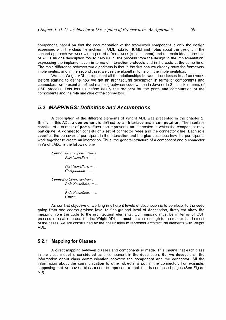
Chapter 5: O. O. Architectural Description of Frameworks: An Approach 59
component, based on that the documentation of the framework component is only the designexpressed with the class hierarchies in UML notation [UML] and notes about the design. In thesecond approach we work with a part of a framework (a component) and the main idea is the useof ADLs as one description tool to help us in the process from the design to the implementation,expressing the implementation in terms of interaction protocols and in the code at the same time.The main difference between two algorithms is that in the first one we already have the frameworkimplemented, and in the second case, we use the algorithm to help in the implementation.
We use Wright ADL to represent all the relationships between the classes in a framework.Before starting to define how we get an architectural description in terms of components andconnectors, we present a defined mapping between code written in Java or in Smalltalk in terms ofCSP process. This lets us define easily the protocol for the ports and computation of thecomponents and the role and glue of the connectors
5.2 MAPPINGS: Definition and Assumptions
A description of the different elements of Wright ADL was presented in the chapter 2.Briefly, in this ADL, a component is defined by an interface and a computation. The interfaceconsists of a number of ports. Each port represents an interaction in which the component mayparticipate. A connector consists of a set of connector roles and the connector glue. Each rolespecifies the behavior of participant in the interaction and the glue describes how the participantswork together to create an interaction. Thus, the general structure of a component and a connectorin Wright ADL is the following one:
Component ComponentNamePort NamePort1 = ...
...Port NamePortn = ...Computation = ...
Connector ConnectorNameRole NameRole1 = ......Role NameRolen = ...Glue = ...
As our first objective of working in different levels of description is to be closer to the codegoing from one coarse-grained level to fine-grained level of description, firstly we show themapping from the code to the architectural elements. Our mapping must be in terms of CSPprocess to be able to use it in the Wright ADL . It must be clear enough to the reader that in mostof the cases, we are constrained by the possibilities to represent architectural elements with WrightADL.
5.2.1 Mapping for Classes
A direct mapping between classes and components is made. This means that each classin the class model is considered as a component in the description. But we decouple all theinformation about class communication between the component and the connector. All theinformation about the communication to other objects is put in the connector. For example,supposing that we have a class model to represent a book that is composed pages (See Figure5.3).

60 Object Oriented Architectural Description of Frameworks
Book
author : Stringtitle : Stringpublisher : String
check()
Pages
number : Integerwords : set of String
check()
1..*1..*
Component Book Connector Has
Component Page 1
Component Page 2
Component Page n
check
check
check
check
Figure 5.3: Class Model for a Book and the Mapping with Connectors and Components
These classes are mapped as two components: Book and Page, and we get a connectorHas which represents the relationship between the two components. The behaviour of thecomponent regarding to the other objects is left to the connector. In this case, for example, whenthe Book wants to do a spelling checking, it just only sends the event to the connector whichforwards the events to the pages. This fact is also illustrated graphically in Figure 5.3.
5.2.2 Mapping for Relationships between Classes
Besides of the relationships that can be mapped by the message sendings (explained inthe next subsection), we also consider three kinds of relationships between two classes A and B.
• instances of B can be instances/class variables of A• instances of B used as parameters in one method of A• instances of B are connected to an instance of A by a dependency mechanism.
In all the cases, we represent A, the instances/class variables of A and the parameters ascomponents in the Wright description whenever the objects are not instances of primitive classes(in Smalltalk) or primitive types (in Java) such as Char, Integer, Boolean. We only want to keepobjects with a composite structure. For example, in the figure 5.4 we can see the class model of aTruck and its representation in terms of components and connectors. It must be clear for the userthat this is a complete representation for this model., this means that we can simply represent theTruck and avoid any information of the Manufacturer. In this case we represent them because weuse the information of the latter. But it is clear that we do not have, for example, a component forthe name of the Manufacturer. All the information (called as simple) can be used as parameters.This assumption is taken because the management of parameters in Wright ADL is limited tosimple parameters such as letters and integers.

Chapter 5: O. O. Architectural Description of Frameworks: An Approach 61
Manufacturer
name : Stringaddress : Stringcity : Stringoffices : Integer
Wheel
material : Stringtrademark : String
1..*1..*
Component Truck Component Manufacturer
Wheel 1
Wheel n
Connector Has
Connector Composed
Truck
driver : Stringmanufacturer : Manufactureryear : String
checkState()
Figure 5.4: Class Model for a Truck and Representation with Components and Connectors
5.2.3 Format for Components and Connectors
As our approach focuses on having components only as units of computation andconnectors as units of communication, we model the classes as components without anyknowledge of what objects are connected with and we leave all this information to the connectors.In this way, the names of the ports in the component are left to the user, but we adopt the namesof the roles in the connector with the names of classes that must be connected. If an instance ofclass A must connect with instances of class B, the connector have the following format:
Connector ABRole A =....Role B1..n = ...Glue = ...
5.2.4 Mapping for the Messages
The method calls in a method mk in a class A have the following formats:• in Smalltalk:
o objecti messagej
o objecti messagej: p1 with: p2 ... with: pn
• in Java:o objecti . messagej
o objecti . messagej (p1, p2, … pn )
where objecti ,p1, p2, … pn can be instances/class variables of A, parameters in the method or theclass itself and messagej can be seen as a service that the class initializes or simply thenotification of a change (dependency mechanism). We are assuming that objects pi have only onelevel of objects' composition in their structure. Following with the example of the Truck (Figure 5.4),p1 can be an instance of the Wheel class, but it can not be an instance of the Truck Class, becausethis latter has two levels of composition. We are making this assumption because we are

62 Object Oriented Architectural Description of Frameworks
interested in being able to decompose the parameter pi in terms of its components px(ox1,..,oxm). Inthe case of Manufacturer, we will get manufacturer(name, address, city, offices). Thus, we get agood level of expressiveness in the description. Based on the structure of methods, let's see thedifferent focus that we have about the methods themselves and their bodies. Firstly, all themethods (mk) are mapped as events in CSP. Thus, we must know if the methods are called by theanother object or if the method is a 'shooter' of actions. In the first case, the method will be mappedas an observing event mk, and in the second case, the method will be mapped as an initiating
event km . So the component A (class A mapped as component in the description) has the
following structure:
Component A
Port Out = ( mk | km ) |
( mk | km _ objectNamejmessage ! _ ),..,1(!;..1 xmoxoxprasParametenx ∀
Computation = ( Out.mk | kmOut. ) |
( Out.mk | kmOut. _ objectNamejmessageOut !.
_ ),..,1(!.;..1 xmoxoxprasParameteOutnx ∀
Connector AB
Role A = ( mk | km ) |
( mk | km _ objectNamejmessage ! _ ),..,1(!;..1 xmoxoxprasParametenx ∀
Role objectName = messagej _ ),..,1(?;..1 xmoxoxprasParametenx ∀
Glue = ( kmA. | A.mk ) _ A.messagej?objectName
_ ),..,1(?.;..1 xmoxoxprasParameteAnx ∀ _ jmessageobjectName.
_ ),..,1(!.;..1 xmoxoxprasParameteAnx ∀
The connector uses a name matching with the parameter objectName and thus identify towhich component (identified with the portname) it sends the events.
5.2.5 Mapping for Classes' Creation
Class A must create instances of classes B in one of its methods, so we find the followingcodeline:
• in Smalltalk:o B newo B new: p1 with: p2 ... with: pn
• in Java:o B ()o B (p1, p2,.., pn)
In the first case, it maps as a special event name Bcreate! in the protocol of thecomponent. The class A is creating an element B so it is an initiating event. In the second case, it
maps as a sequence of events Bcreate! _ ),..,1(!;..1 xmoxoxprasParametenx ∀

Chapter 5: O. O. Architectural Description of Frameworks: An Approach 63
5.2.6 Mapping for Conditional Statements
In the methods calls we can also have a conditional statements.• in Smalltalk:
o (condition) ifTrue: [actionTrue]o (condition) ifFalse: [actionFalse]o (condition) ifTrue: [actionTrue] ifFalse: [actionFalse]o (condition) ifFalse: [actionFalse] ifTrue: [actionTrue]o (condition) whileTrue: [action]o (condition) whileFalse: [action]o 1 to: n do: [action]
• in Java:o if (condition) actionTrueo if (condition) actionTrue else actionFalseo while (condition) actiono for (i:=0; i++; i<=n) action
where the condition can only be one boolean expression (e1) or a set of boolean expressions(e1,..,en) joined by logic operators (and, or, xor), and the action, actionTrue and actionFalse can bea method call (m1) or a sequence of method calls (m1,..mk) (as we explained previously). In thecase of expressions, they are method calls which reply True or False. Thus in both cases, weconsider them as events inside the description.
Firstly, we study the condition. The expressions e1,..,en are a sequence of method calls(except in the case they evaluate an internal state of the object, e.g. comparing two values ofinstances variables), so we map the condition such as:
Process Condition = xenx ;..1∀ _ (answer?True _ ... _ answer?False _ … )
Thus we leave the responsability of evaluating the logic expression to the connector. Let'ssee how the process in the connector would be modeled.
Connector Logic (nb: 1..n)Port A = Condition
Port B1..nb = ej _ ( Trueanswer! _ B _ Falseanswer! _ B )
Computation = xeAnx .(;..1∀ _ exB . )
if the logic operator is 'and' : TrueanswerxBnx ?.;..1∀ _ TrueanswerA !.
_ FalseanswerxBnx ?.;..1∃ _ FalseanswerA !.
if the logic operator is 'or' : TrueanswerxBnx ?.;..1∃ _ TrueanswerA !.
_ FalseanswerxBnx ?.;..1∀ _ FalseanswerA !.
We consider the possibility of expressing explicitly the condition. But if the user decides toavoid it, the events to execute when the condition is true or false are expressed as nondeterministic choice because we do not have any information about the condition, so we can thinkthat the component takes the decision of the actions to follow. In the other case, we must use thedeterministic choice, because it has an observing event (answer) which communicates the result ofthe condition. Let's see how it works.The if-statement maps as a non deterministic choice with the following format:
Process if = actionTrue (or xactionTruenx ;..1∀ )
_ eactionFals (or xeactionFalsnx ;..1∀

64 Object Oriented Architectural Description of Frameworks
But in the case of using the condition explicitly:
Process if = all the conditions are sent _
(answer?True _ actionTrue (or xactionTruenx ;..1∀ )
_ answer?False _ eactionFals (or xeactionFalsnx ;..1∀ )
In the case of WHILE-statement, using non-deterministic choice:
Process While = action (or xactionnx ;..1∀ ) _ While _ §
But using a deterministic choice:
Process While = all the conditions are sent _
(answer?True _ action (or xactionnx ;..1∀ ) _ While
_ answer?False _ § )
The For-statement maps as a non deterministic choice with the following format:
Process For = action (or xactionnx ;..1∀ ) _ For _ §
But using a deterministic choice:
Process For = execute0
where executei = action (or xactionnx ;..1∀ ) _ executei+1) when i in 1..n
§ otherwise.
5.3 Object oriented Architectural Description - First Case:Design and Code
Based on different object oriented application frameworks we have developed an algorithm(set of steps) to infer a possible architecture which represents the set of classes and differentrelationships between them. The main idea is just to infer a set of components and connectorswhich shows the complete behaviour of an application framework. We show two approaches:
1. Use of Predefined Style: components and connectors defined in other configurations2. Use of Steps: Start from the « scratch » following closer to the design and
implementation decisions made in the frameworkFirstly, we explain why we decided not to take the first approach as our main approach.
We use an example for both cases, because it will turn the process more illustrative andunderstandable.
5.3.1 Example: Measurements System Framework [Bos00]
Measurement systems are a class of systems to measure the relevant values of a processor product. It is used for quality control of parts entering production or of produced products thatcan then be used to separate acceptable from unacceptable items to categorize the products inquality categories.
A measurement system consists of more than sensors and actuators. A typicalmeasurement cycle starts with a trigger, indicating that a product, or a measurement item, is
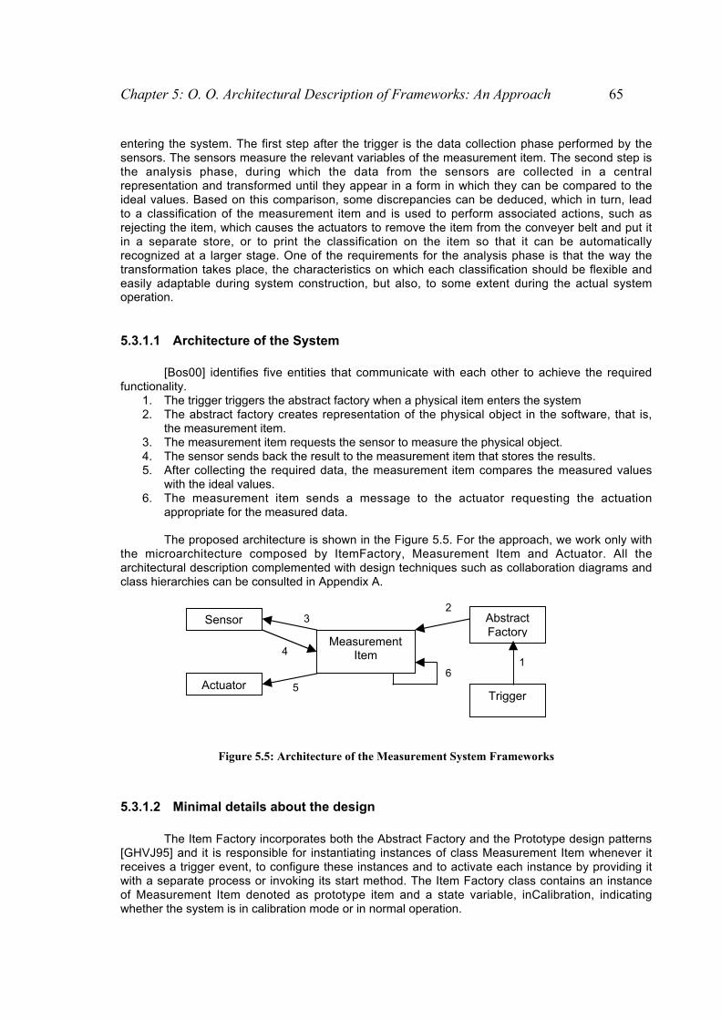
Chapter 5: O. O. Architectural Description of Frameworks: An Approach 65
entering the system. The first step after the trigger is the data collection phase performed by thesensors. The sensors measure the relevant variables of the measurement item. The second step isthe analysis phase, during which the data from the sensors are collected in a centralrepresentation and transformed until they appear in a form in which they can be compared to theideal values. Based on this comparison, some discrepancies can be deduced, which in turn, leadto a classification of the measurement item and is used to perform associated actions, such asrejecting the item, which causes the actuators to remove the item from the conveyer belt and put itin a separate store, or to print the classification on the item so that it can be automaticallyrecognized at a larger stage. One of the requirements for the analysis phase is that the way thetransformation takes place, the characteristics on which each classification should be flexible andeasily adaptable during system construction, but also, to some extent during the actual systemoperation.
5.3.1.1 Architecture of the System
[Bos00] identifies five entities that communicate with each other to achieve the requiredfunctionality.
1. The trigger triggers the abstract factory when a physical item enters the system2. The abstract factory creates representation of the physical object in the software, that is,
the measurement item.3. The measurement item requests the sensor to measure the physical object.4. The sensor sends back the result to the measurement item that stores the results.5. After collecting the required data, the measurement item compares the measured values
with the ideal values.6. The measurement item sends a message to the actuator requesting the actuation
appropriate for the measured data.
The proposed architecture is shown in the Figure 5.5. For the approach, we work only withthe microarchitecture composed by ItemFactory, Measurement Item and Actuator. All thearchitectural description complemented with design techniques such as collaboration diagrams andclass hierarchies can be consulted in Appendix A.
Figure 5.5: Architecture of the Measurement System Frameworks
5.3.1.2 Minimal details about the design
The Item Factory incorporates both the Abstract Factory and the Prototype design patterns[GHVJ95] and it is responsible for instantiating instances of class Measurement Item whenever itreceives a trigger event, to configure these instances and to activate each instance by providing itwith a separate process or invoking its start method. The Item Factory class contains an instanceof Measurement Item denoted as prototype item and a state variable, inCalibration, indicatingwhether the system is in calibration mode or in normal operation.
Sensor
Actuator
MeasurementItem
AbstractFactory
Trigger
16
5
4
32

66 Object Oriented Architectural Description of Frameworks
This system can be in two possible states: Normal or Calibration state. In the Normal state,the system works exactly as it was described in the steps previously. But if it is in Calibration state,the Item Factory and the Measurement Item both play a role. The Item Factory contains aninstance of Class Measurement Item that it is used as a prototype for generating measurementitems during normal system operation. When the user of the system decides to calibrate, the firststep is to notify the item Factory that the next measurement item is to be used for calibration.When the trigger notifies the item factory, the item factoy instantiates a measurement item, butreplaces the normal actuation strategy with a calibration strategy. This causes the item factory toreplace its current prototype item with the last measurement item. Now, all following trigger eventswill result, in that the item factory instantiates a copy of the measurement item now stored as theprototype item; in other words, the prototype measurement item contains the new set values.
The measurement item is the object that contains the data collected from the sensorsconcerning the physical measurement item. It is invoked via its start method by the item factoryafter it has instantiated the item. The start method contains the top-level behavior for themeasurement item with respect to its primary task – to collect data on the physical item itrepresents and to actuate the actuators appropriately, based on the measured data and thecomparison to the set data.
The calculation phase of the measurement item is concerned with collecting the data andconverting it to a value form that matches the requirements within the system. The only actionperformed by the measurement item is to invoke each measurement value that it contains with arequest to collect the data from the sensor to which the measurement value is connected and toprocess this data. The actuation phase is concerned with generating the necessary effects on theactuators, based on the values collected during the calculation phase. In the case of Calibrationstate, the actuators are not considered and the actuation strategy provokes that the item factorymakes a new prototype using the last measurement item as a basis.
5.3.2 First Approach: Use of Predefined Styles
The first approach is based on the use of predefined styles given in other systems’description using Wright ADL].
Supposing that we identify the classes Item Factory and Measurement Item ascomponents, and we analyze the behaviour between these two classes. We can consider that thebehaviour can be mapped as a seudo Master/Slave style, where the master is the Item Factoryand the slave is the Measurement Item. The item factory creates objects to measure specificvalues on a physical item, and when the task is done, and if the item factory has not to copy thelast measurements as the new prototype, it destroys the object. Behind these conditions, weestablish the relationship between them in terms of master/slave style and we used a predefinedstyle (shown in the figure 5.6).
Interface Type SlavePullT = open _ Operate _ §
where Operate = request _ result?x _ Operate _ close _ §
Interface Type MasterPushT = open _ Operate _ §
where Operate = request _ xresult! _ Operate _ close _ §
Connector MasterSlaveRole Slave = SlavePullTRole Master = MasterPushT
Glue = Slave.open _ openMaster. _ Glue
_ Slave.close _ closeMaster. _ Glue
_ Slave.request _ requestMaster. _ Glue
Factory
Item
Master
Slave
MasterSlave
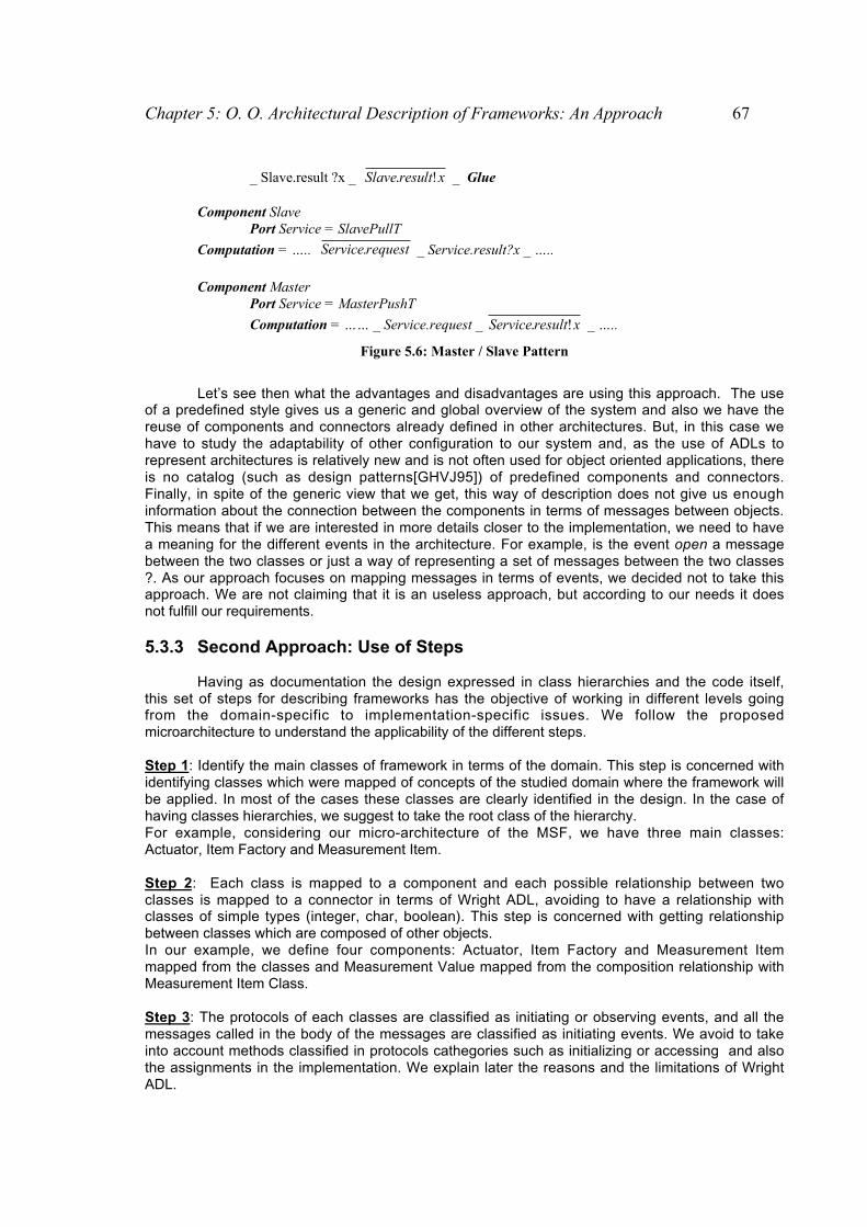
Chapter 5: O. O. Architectural Description of Frameworks: An Approach 67
_ Slave.result ?x _ xresultSlave !. _ Glue
Component Slave Port Service = SlavePullT
Computation = ….. requestService. _ Service.result?x _ …..
Component MasterPort Service = MasterPushT
Computation = …… _ Service.request _ xresultService !. _ …..
Figure 5.6: Master / Slave Pattern
Let’s see then what the advantages and disadvantages are using this approach. The useof a predefined style gives us a generic and global overview of the system and also we have thereuse of components and connectors already defined in other architectures. But, in this case wehave to study the adaptability of other configuration to our system and, as the use of ADLs torepresent architectures is relatively new and is not often used for object oriented applications, thereis no catalog (such as design patterns[GHVJ95]) of predefined components and connectors.Finally, in spite of the generic view that we get, this way of description does not give us enoughinformation about the connection between the components in terms of messages between objects.This means that if we are interested in more details closer to the implementation, we need to havea meaning for the different events in the architecture. For example, is the event open a messagebetween the two classes or just a way of representing a set of messages between the two classes?. As our approach focuses on mapping messages in terms of events, we decided not to take thisapproach. We are not claiming that it is an useless approach, but according to our needs it doesnot fulfill our requirements.
5.3.3 Second Approach: Use of Steps
Having as documentation the design expressed in class hierarchies and the code itself,this set of steps for describing frameworks has the objective of working in different levels goingfrom the domain-specific to implementation-specific issues. We follow the proposedmicroarchitecture to understand the applicability of the different steps.
Step 1: Identify the main classes of framework in terms of the domain. This step is concerned withidentifying classes which were mapped of concepts of the studied domain where the framework willbe applied. In most of the cases these classes are clearly identified in the design. In the case ofhaving classes hierarchies, we suggest to take the root class of the hierarchy.For example, considering our micro-architecture of the MSF, we have three main classes:Actuator, Item Factory and Measurement Item.
Step 2: Each class is mapped to a component and each possible relationship between twoclasses is mapped to a connector in terms of Wright ADL, avoiding to have a relationship withclasses of simple types (integer, char, boolean). This step is concerned with getting relationshipbetween classes which are composed of other objects.In our example, we define four components: Actuator, Item Factory and Measurement Itemmapped from the classes and Measurement Value mapped from the composition relationship withMeasurement Item Class.
Step 3: The protocols of each classes are classified as initiating or observing events, and all themessages called in the body of the messages are classified as initiating events. We avoid to takeinto account methods classified in protocols cathegories such as initializing or accessing and alsothe assignments in the implementation. We explain later the reasons and the limitations of WrightADL.
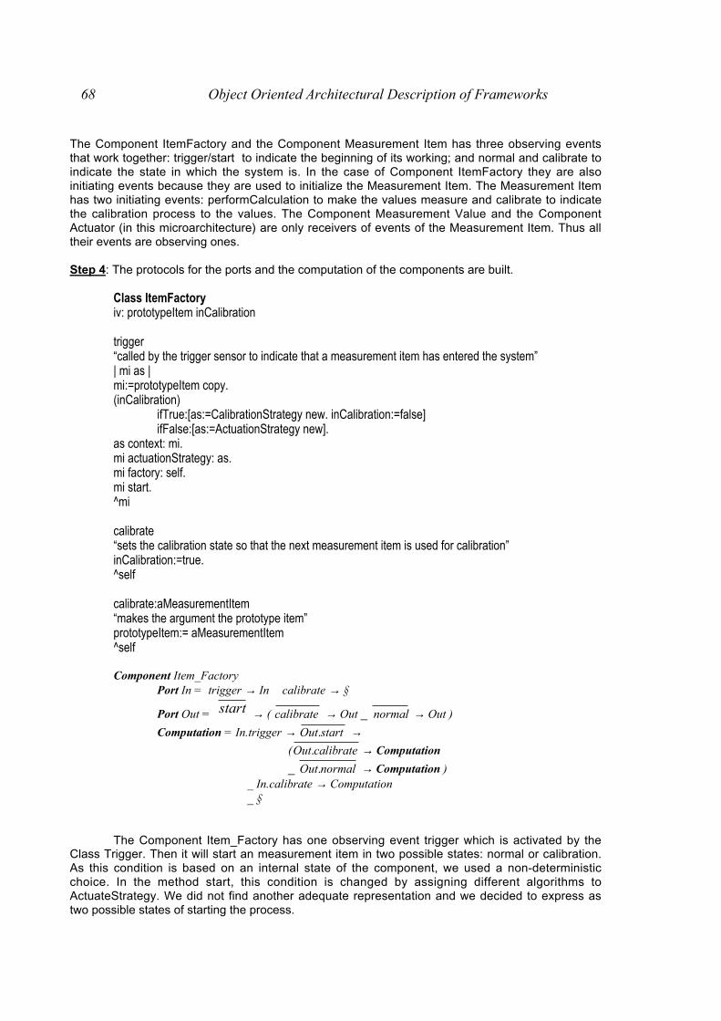
68 Object Oriented Architectural Description of Frameworks
The Component ItemFactory and the Component Measurement Item has three observing eventsthat work together: trigger/start to indicate the beginning of its working; and normal and calibrate toindicate the state in which the system is. In the case of Component ItemFactory they are alsoinitiating events because they are used to initialize the Measurement Item. The Measurement Itemhas two initiating events: performCalculation to make the values measure and calibrate to indicatethe calibration process to the values. The Component Measurement Value and the ComponentActuator (in this microarchitecture) are only receivers of events of the Measurement Item. Thus alltheir events are observing ones.
Step 4: The protocols for the ports and the computation of the components are built.
Class ItemFactoryiv: prototypeItem inCalibration
trigger“called by the trigger sensor to indicate that a measurement item has entered the system”| mi as |mi:=prototypeItem copy.(inCalibration)
ifTrue:[as:=CalibrationStrategy new. inCalibration:=false]ifFalse:[as:=ActuationStrategy new].
as context: mi.mi actuationStrategy: as.mi factory: self.mi start.^mi
calibrate“sets the calibration state so that the next measurement item is used for calibration”inCalibration:=true.^self
calibrate:aMeasurementItem“makes the argument the prototype item”prototypeItem:= aMeasurementItem^self
Component Item_FactoryPort In = trigger → In calibrate → §
Port Out = start → ( calibrate → Out _ normal → Out )
Computation = In.trigger → startOut. → ( calibrateOut. → Computation
_ normalOut. → Computation ) _ In.calibrate → Computation
_ §
The Component Item_Factory has one observing event trigger which is activated by theClass Trigger. Then it will start an measurement item in two possible states: normal or calibration.As this condition is based on an internal state of the component, we used a non-deterministicchoice. In the method start, this condition is changed by assigning different algorithms toActuateStrategy. We did not find another adequate representation and we decided to express astwo possible states of starting the process.

Chapter 5: O. O. Architectural Description of Frameworks: An Approach 69
Class MeasurementItemiv: sensor, measurementValues, actuators, myItemFactory actuationStrategy
performCalculationmeasurementValues do:[ :n | n performCalculation]^self
calibrate“perform calibration”measurementValues do: [:mv | mv calibrate]
start(self calculationStrategy) performCalculation.(self actuationStrategy) actuate^self
Component Measurement_ItemPort In = start → (normal → In _ calibrate → In)
Port Out = culationperformCal → Out _ calibrate → Out
_ actuate→ OutComputation = In.start →
( In.calibrate→ culationperformCalOut. → calibrateOut.
In.normal→ culationperformCalOut. → actuateOut. )
→ Computation _ §
The component protocol is very simple. Once the measurement item is created in bothstates, just ask for the measurements to the measurements values.
Class MeasurementValue
performCalculation
calibrate
Component C_MeasurementValuePort In = performCalculation → In _ calibrate → InPort Out = …Computation = In.perform_calculation
→ “call the sensors” → Computation _ In.calibrate
→ “calibrate their values” → Computation _ §
The Measurement Value and Actuator are also simple because just only receives therequests from the Measurement Item and executes their requests.
Class Actuator
actuate“Perform the actuation associated with this actuator”

70 Object Oriented Architectural Description of Frameworks
inActuation value:true.(hardwareActuator isNil) ifFalse: [hardwareActuator actuate].InActuation value:false.^self
Component ActuatorPort In = actuate → InComputation = In.actuate → “call the actuators” → …→ Computation
Step 5: The connectors are built using the messages sent from one class to another one. In thiscase, we have three connectors Item_MI, MI_Act and MI_MV.
Connector IF_MI
Role IFactory = start → ( calibrate → IFactory _ normal → IFactory)
Role Mitem = calibrate → Mitem_ start → (normal → MItem _ calibrate → Mitem)
Glue = IFactory.start → startMItem. →(IFactory.normal → normalMItem. → Glue
_ IFactory.calibrate → calibrateMItem. → Glue)
Connector MI_MV (numMvs: 1..)
Role MI = culationperformCal → MI _ calibrate → MI
Role MValues 1..numMVs = perform_calculation → MValues _ calibrate → MValues
Glue = MI.perform_calculation →numMVsi ..1:∀ ; culationperformCaliMValues . → Glue
_ MI.calibrate → numMVsi ..1:∀ ; calibrateiMValues . → Glue
_ §
Connector MI_Act (numAct: 1..)
Role MI = actuate → MIRole Actuators1..numAct = actuate → Actuators
Glue = MI.actuate → numActi ..1:∀ ; actuateiActuators . → Glue _ §
Step 6: Identify the variations of the one component (each subclass of a root class) and what othercomponents related to the component must be changed. In the first step we identify abstractclasses in the case of having class hierarchies to have the components in the first description. Butthis component is just one prototype of other components that can be mapped from thesubclasses. Thus, if we have a class hierarchy, the idea is just to take each subclass, to see whatother classes are related and then map them as components. Then, repeat the process from thestep 3 until getting different versions of the description. In our example, the studied framework issmall and all the classes were mapped in the first run of this algorithm. But in frameworks in large-scale, this step can be applied.
Step 7: Identify the components that represent hotspots and frozen spots. This step is focused toidentify which components and connectors are fixed (this situation can be detected in the differentdescriptions obtained from the Step 6) and which ones are candidates to be changed in terms of aframework instantiation. In the microarchitecture that we are studying, all the components arefrozen spots except the actuator which can customize its behaviour in the process actuate.

Chapter 5: O. O. Architectural Description of Frameworks: An Approach 71
Step 8: At this step, we have a first level of description. We can identify predefined architecturalstyles in terms of set of classes or just components and connectors with an specific behaviour. Forexample it is possible to prove that the relationship between Measurement Item and MeasurementValues is managed by the connector, when the measurement item needs information from theirvalues, just only send the event to the connector and the connector makes the task of forwardingthe same request to all the measurement values and also process the final results for theMeasurement Item obtained from all the partial results of the Measurement Values
Step 9: We run the tool to verify the different properties in Wright.1. Port Computation Consistency (component)2. Connector Deadlock-Free (connector)3. Roles Deadlock-Free (role)4. Single Initiator (connector)5. Initiator Commits (any process)6. Parameter Substitution (instance)7. Range Check (instance)8. Port-Role Compatibility (attachment)9. Style Constraints (configuration)10. Style Consistency (style)11. Attachment Completeness (configuration)
This step just only ensures us that our description is valid using Wright ADL. If there is an errorreported by the tool, we should check it following the format defined in the Steps describedpreviously.
Step 10: Refine each component considering• if we have a hierarchical composition of objects that work together (definition of
microarchitectectures). This step is concerned to discover if there is a component that iscomposed of other objects and the different services that it offers are made using theseobjects. All the objects must be inside the ‘boundaries’ of the main object to consider it as ahierarchical composition. This means that for example, we can consider in this Step thecomposition relationship between Measurement Values and Measurement Item because theitem calls the services of the values and the values call the sensors to do it, and all theinformation is returned to the measurement item. The possibility of using hierarchicalcomposition will let us this kind of description.
• If there is a set of events joined by a non-deterministic choice which indicates a decision ofthe component regarding an internal state (internal state of the component). This step isconcerned with expressing all the information related to the component avoiding to have non-deterministic choices. For example, in the case of Measurement Item there is a decision ofstarting in normal or calibration state. In fact, this choice depends on a boolean variable of theMeasurement Item. The possibility of using Abstract Machines B let us this modification in thecomponent.
Step 11: New components (not necessarily mapped from domain concepts) can be discovered.This step is concerned with having a new level of description. If this situation happens, it issuggested to start to study the component as a microarchitecture and follow again the steps onlywith the new components.If we are interested in refining the behaviour of the component, this step is also concerned withhaving detailed information about the defined behaviour protocol in the components. For example,in the method start of the Measurement Item there are calls to Calculation Strategy and ActuationStrategy because the Calculation strategy is used to coordinate what actions must be made forcollecting and converting data from one representation into another and Actuation Strategy is usedto coordinate what actions must be made for generating the necessary effects on the actuators.

72 Object Oriented Architectural Description of Frameworks
Step 12: Definition of the interaction protocols in interface types and association of frozen spotsand hotspots in styles. This step is concerned with identifying the set of events that belong to aninteraction protocol and defining styles for the fixed part and variable points of the framework. Thiswill let us to have a clear view of how the framework is composed and measures the impacts ofpossible changes in its structure and object behaviour.
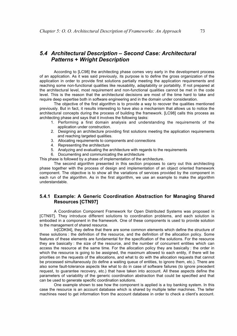
Chapter 5: O. O. Architectural Description of Frameworks: An Approach 73
5.4 Architectural Description – Second Case: ArchitecturalPatterns + Wright Description
According to [LC98] the architecting phase comes very early in the development processof an application. As it was said previously, its purpose is to define the gross organization of theapplication in order to provide first solutions partially meeting the application requirements andreaching some non-functional qualities like reusability, adaptability or portability. If not prepared atthe architectural level, most requirement and non-functional qualities cannot be met in the codelevel. This is the reason that the architectural decisions are most of the time hard to take andrequire deep expertise both in software engineering and in the domain under consideration.
The objective of the first algorithm is to provide a way to recover the qualities mentionedpreviously. But in fact, it results interesting to have also a mechanism that allows us to notice thearchitectural concepts during the process of building the framework. [LC98] calls this process asarchitecting phase and says that it involves the following tasks:
1. Performing a first domain analysis and understanding the requirements of theapplication under construction.
2. Designing an architecture providing first solutions meeting the application requirementsand reaching targeted qualities.
3. Allocating requirements to components and connections4. Representing the architecture5. Analyzing and evaluating the architecture with regards to the requirements6. Documenting and communicating the architecture
This phase is followed by a phase of implementation of the architecture.The second algorithm presented in this section proposes to carry out this architecting
phase together with the process of design and implementation of an object oriented frameworkcomponent. The objective is to show all the variations of services provided by the component ineach run of the algorithm. As in the first algorithm, we use an example to make the algorithmunderstandable.
5.4.1 Example: A Generic Coordination Abstraction for Managing SharedResources [CTN97]
A Coordination Component Framework for Open Distributed Systems was proposed in[CTN97]. They introduce different solutions to coordination problems, and each solution isembodied in a component in the framework. One of these components is used to provide solutionto the management of shared resource.
In[CDK94], they define that there are some common elements which define the structure ofthese solutions : the definition of the resource, and the definition of the allocation policy. Somefeatures of these elements are fundamental for the specification of the solutions. For the resourcethey are basically : the size of the resource, and the number of concurrent entities which canaccess the resource at the same time. For the allocation policy they are basically : the order inwhich the resource is going to be assigned, the maximum allowed to each entity, if there will bepriorities on the requests of the allocations, and what to do with the allocation requests that cannotbe processed simultaneously (to define a waiting queue of entities, to ignore them, etc.). There arealso some fault-tolerance aspects like what to do in case of software failures (to ignore precedentrequest, to guarantee recovery, etc.) that have taken into account. All these aspects define theparameters of variability of the generic coordination abstraction that could be specified and thatcan be used to generate specific coordination solutions.
One example shown to see how the component is applied is a toy banking system. In thiscase the resource is an account database which is shared by multiple teller machines. The tellermachines need to get information from the account database in order to check a client’s account.

74 Object Oriented Architectural Description of Frameworks
They also need to update account information if they have given money to a client. To keep thedatabase consistent we need an access policy to regulate the multiple requests.
As a solution for this regulation they introduce an access policy component. This solutionnot only provides access regulation, but also explicitness of architecture and flexibility.
5.4.2 Requirements
The main goal of the design is to implement the access policy to the database in areusable and configurable way. In terms of the component oriented approach, this means that wewant to have a structure where we can plug in different policies, without having to change otherparts of the solution. Three kinds of policies are distinguished:
• Policies that need no other information about the requests: This is the easiest kind ofpolicy. They can do their job without any knowledge about the commands they have todispatch. A typical example is a FIFO policy: no matter what commands come in, thepolicy just dispatches them in order they come in.
• Policies that need type information about the requests: This kind of policy depends onthe “nature” of the command: every commandtype has one or more properties which areneeded by the policy. A typical example for this case is the readers/writers policy. Thepolicy has to know if a command is a reader or a writer command. So this informationmust be made available in our solution.
• Policies that need external information about the requests: This kind of policy dependson information which can be different for each instance of a command. It can be thoughtas a priority policy, where, depending on the sender of the request, a command has acertain priority. Again, somehow this information must be available to the policy.
5.4.3 Solution
There is an Interface of the solution to the rest of the application. Clients have to call thisInterface to access the access solution. The resource itself is also modelled and there is a partwhich represents the control policy. To give the policy the ability to buffer the commands, changetheir order or execute them in parallel, it is necessary an explicit representation of the commands.This is done using the Command Pattern [GHVJ95].
Then let’s see the relationship between Command and Policy. For the first kind of policy,the basic Command pattern suffices. For the second kind of policy, we need to make typeinformation available at run-time in order to be able to use this information at run-time, for instanceto link this information to certain policy-dependent properties. We make this information availableby providing a CommandType class to every subclass of the abstract Command class.
For the third kind of policy we need to make information available which can differ for everyinstance of a command. We do this by connecting a Property class to every Command class andthe addition of a SetProperty and a GetProperty method to the Command class. What the exactinformation is, that subclasses of this class represent, is totally dependent on the application inwhich it is used. It could be that the name of the sender of the request is made available. Theinformation, that is made available, should not be information especially linked to a policy. As anexample, we take again the priority policy. In the Property object, we should make the sender of arequest available. The linking of this sender with a priority is done later at the policy. We do this tokeep the Command as independent of the policy as possible: the information is really a property ofthe Command and this information can be used by different policies.
The Policy part is set up using the Strategy pattern [GHVJ95]. The hard part is again thefact that we have to deal with the application dependent information. The solution is to representthis information explicitly in so-called “configuration” objects. These configuration objects contain atrun-time the information that is needed by the policies. So we may have, for example, aconfiguration object that contains of a link between command types and a property isReader.Another example is an object that links the names of possible request senders to a certain priority.We see here the difference between information that is made available in a Property object and

Chapter 5: O. O. Architectural Description of Frameworks: An Approach 75
that in a Configuration object. The former is general information, the latter contains the policydependent information.
In figure 5.7, we see the total design for the shared resource access policy solution. Theclass Interface is the interface to the resource for the rest of the system. For every command whichis invoked by an incoming events, a Command object is created. These commands are then givento the policy which is connected (through parameterization) to the interface. This policy handles thecommands, i.e. determines when and in which order the request can access the resource. If thecommand is allowed, it is executed.
Concrete Command
execute()
ConcreteProperty
Property
Resource
request()
Command Type
FIFOPolicy ReadersWriters Policy
RW Configuration
Priority Policy
PrConfiguration
Interface
request()
Command
execute()setProperty()getProperty()
Policy
Concrete Command Type
Figure 5.7: Class Model for the Shared Resource Access Policy
5.4.4 Approach: Use of Steps
Step 1: Can we apply any known architectural pattern in our model ?It is possible to use the guidelines proposed in [BMR+96] and [SG96] to identify some
architectural patterns that can be applied:" Control decomposition of an overall system task into cooperating subtasks: Layers, Pipers and
Filters, Blackboard" Infrastructure for distributed applications: Pipes and Filters, Microkernel, Broker" Support the structure of software systems that feature human-computer interaction: Model-
View-Controller, Presentation-Abstraction-Controller" Support the extension of applications and their adaptation to evolving technology and changing
functional requirements: Microkernel, Reflection.
Clearly, as we explained in the chapter 2, the domains and the models allow us to applynone, one or a combination of several architectural patterns. Unfortunately, we can not give anexample of the use of an architectural pattern with the framework that we use as example in thisalgorithm. But we studied other components’ frameworks in a larger scale, and we discovered alarge applicability of the Layers Architectural Pattern. For example, in [BGK+97] they document thedevelopment of a framework for application covering almost the entire area of banking: tellers,loans, stocks and investments departments as well as self-services facilities. In the class model,they use layered framework (shown in the figure 5.8), where the Application Layers provide the

76 Object Oriented Architectural Description of Frameworks
software support for the different workplace contexts, Business Section Layers consists offrameworks with specific classes for each business section and Business Domain Layer containsthe core concepts for the business as a whole.
Investor
Client
Borrower Guarantor
CustomerCore CustomerRole
1..*
+roles
1..*
Customer
core
Figure 5.8: Example of Application of Layers Architectural Pattern
Next steps of the algorithm are focused on the description of each layer or eachcomponent in the framework.
Step 2: Classify and categorize your abstract classes in the model of connectors and components.In this step, the objective is to define the semantic function of the different classes inside
the model. We define semantic function as the kind of task that the class fulfils inside the model,avoiding to have just only a set of classes without any meaning for the developer or the designers.The main idea is to divide the classes in two sets: units of computation (components) and units ofcommunication (connectors). To do this process, we propose:1. To make a preliminar mapping of each class in a component according to their activity in the
model: processing, data, connecting, controller, coordinator, interface, service provider,information holder or structuring components. In our example, we classify Command andResource classes as data components, Policy as coordinator component and Interface asconnecting component (although it can be classified as coordinator or interface component).
2. To “reclassify” some components to convert them in connectors following the table 1. Thisconversion is a variant using a mixture of the categorization of components presented in thechapter 4. In our case, the result is Command and Resource are components and Interface andPolicy are connectors.
Preliminar Mapping Final Mapping: Architectural Element
Processing Components ComponentData Components ComponentConnecting Components ConnectorController Components ConnectorCoordinator Components ConnectorInterface Components ConnectorService Provider Components Component/ConnectorInformation Holder Components Component
ApplicationLayer
BusinessDomain Layer
BusinessSection Layer
Chapter 5: O. O. Architectural Description of Frameworks: An Approach 77
Structuring Components Component
Table 5-1: Mapping for Architectural Element
Step 3: Study the relationships between the different classes represented as components to mapthem as connectors. The last step allows to identify classes as components or connectors, but infact, there are classes mapped as components and they do not have any evident connectors, orany class which fulfills this function. The idea of this step is to capture these relationships in aconnector. The reason is that we must express the interrelationships between components asexplicit connectors with Wright ADL. As it was defined in the section about Mappings forConnectors, there are three ways in which classes A and B: instances of B can be instances/classvariables of A, instances of B are used as parameters in one method of A and instances of B areconnected to an instance of A by a dependency mechanism . In these cases the connectors canbe as simple as sender-receivers of events without any other events, in the best case theconnector will have a function such as distribution of events. In our example, the Commandcomponent has the former relationship with Resource, so we express this relationship as aconnector.
Step 4: Using Wright ADL, define the protocol of the components or connectors based on theinformation of the classes and their possible interactions.
This step help us to identify the set of messages and different states of the object that weneed in the model. From our example, we take two connectors (Interface and Policy) and twocomponents (Command and Resource) to analyze.
Connector Interface: This element represents the entry point to the framework component, so weneed two events: one to indicate that we received a request to be executed (request) and one toindicate that this request has to be processed according to the policy (create). The event request isan observing event and the event create is an initiating event. This connector represents therelationship between the external users of the component and the Command component.
Component Command: This element represents the request that will be executed in the resource.It has three events: create (indicates that it was created), put (indicated that it is enqueued in thepolicy to wait for the moment to be executed) and execute (indicates that it can be executed). Theevents create and execute are observing events and the event put is an initiating event.
Component Resource: This element in any context can answer to three states associated toevents : free (it can accept any request), request (it receives the request), busy (it is processing arequest).
Connector Policy: This element represents the algorithm that administrates the order of executionof the commands. This connector receives the Commands components and gives the order ofexecution to work on the resource. It has associated three events: put (indicates that it received aCommand), execute (indicates that a Command can start to work on the resource), and ready(indicates that the resource is free).
Step 5: Model the set of events in the Ports of the components and the Roles of the conectors andthe chain of events in the Computation and Glue of the components and connectors respectively.Following from the last step we show the definition of the protocols of the two components and thetwo connectors.
Connector Interface: We assume that we have only one type of request to be executed.
Connector Interface

78 Object Oriented Architectural Description of Frameworks
Role User = request _ _ §
Role Command = create _ Command
Computation = User.request _ createCommand . _ Computation
Component Command: The restriction is that once it is created, it must be enqueued in the policyqueue and has to wait for its turn to execute. This restriction is shown in the Computation
Component CommandPort In = create _ In
Port Out_Policy = put _ Out_Policy _ execute _ ready _ §
Computation = In.create _ putPolicyOut ._ _ Out_Policy.execute
_ “execute the work on the resource” _ readyPolicyOut ._ _ §
Connector Policy:
Connector Policy
Role Command = put _ Command _ execute _ ready _ §
Computation = Command.put _ executeCommand._ Command.ready _ Computation _ §
Component Resource: The only condition to be fullfilled is that while the resource is availablesends the event free. But when it receives the request, it has to notify that the state is busy andthat can not execute the request event. Both conditions are shown in the computation of thecomponent.
Component Resource
Port In = execute _ In _ free _ In _ busy _ In _ §
Computation = freeIn. _ In.execute _ Continue _ Computation
where Continue = In.execute _ busyIn. _ Continue _ §
Step 6: Use the Wright tool to check all the properties in a description and solve the possibleproblems.
1. Port Computation Consistency (component)2. Connector Deadlock-Free (connector)3. Roles Deadlock-Free (role)4. Single Initiator (connector)5. Initiator Commits (any process)6. Parameter Substitution (instance)7. Range Check (instance)8. Port-Role Compatibility (attachment)9. Style Constraints (configuration)10. Style Consistency (style)11. Attachment Completeness (configuration)This step just only ensures that our description is valid using Wright ADL. If there is an
error reported by the tool, we should check it following the format defined in the steps definedpreviously.
Step 7: Analyze the interface where there is a non-deterministic choice to see if the componentmust have an internal state to take some decisions.
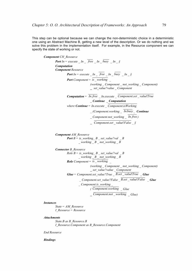
Chapter 5: O. O. Architectural Description of Frameworks: An Approach 79
This step can be optional because we can change the non-deterministic choice in a deterministicone using an Abstract Machine B, getting a new level of the description. Or we do nothing and wesolve this problem in the implementation itself. For example, in the Resource component we canspecify the state of working or not.
Component CH_Resource
Port In = execute _ In _ free _ In _ busy _ In _ §
ComputationComponent Resource
Port In = execute _ In _ free _ In _ busy _ In _ §
Port Component = workingis _ _
(working _ Component _ not_working _ Component)_ set_value?value _ Component
Computation = freeIn. _ In.execute _ TruevaluesetComponent !_.
_ Continue _ Computation
where Continue = In.execute _ isWorkingComponent.
_ (Component.working _ busyIn. _ Continue
_ Component.not_working _ freeIn. )
_ FalsevaluesetComponent !_. _ §
Component AM_ResourcePort B = is_working_ B _ set_value?val _ B
_ working _ B _ not_working _ B
Connector B_ResourceRole B = is_working_ B _ set_value?val _ B
_ working _ B _ not_working _ B
Role Component = workingis _ _
(working _ Component _ not_working _ Component)_ set_value?value _ Component
Glue = Component.set_value?True _ TruevaluesetB !_. _ Glue
_ Component.set_value?False _ FalsevaluesetB !_. _ Glue
_ Component.is_working _
( workingComponent. _ Glue
_ workingnotComponent _. _ Glue)
InstancesState = AM_ResourceI_Resource = Resource
AttachmentsState.B as B_Resource.BI_Resource.Component as B_Resource.Component
End Resource
Bindings
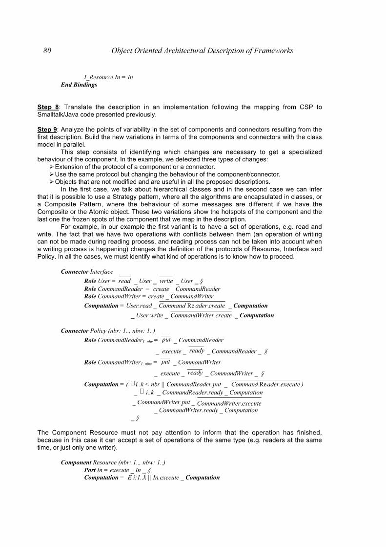
80 Object Oriented Architectural Description of Frameworks
I_Resource.In = InEnd Bindings
Step 8: Translate the description in an implementation following the mapping from CSP toSmalltalk/Java code presented previously.
Step 9: Analyze the points of variability in the set of components and connectors resulting from thefirst description. Build the new variations in terms of the components and connectors with the classmodel in parallel.
This step consists of identifying which changes are necessary to get a specializedbehaviour of the component. In the example, we detected three types of changes:
" Extension of the protocol of a component or a connector." Use the same protocol but changing the behaviour of the component/connector." Objects that are not modified and are useful in all the proposed descriptions.
In the first case, we talk about hierarchical classes and in the second case we can inferthat it is possible to use a Strategy pattern, where all the algorithms are encapsulated in classes, ora Composite Pattern, where the behaviour of some messages are different if we have theComposite or the Atomic object. These two variations show the hotspots of the component and thelast one the frozen spots of the component that we map in the description.
For example, in our example the first variant is to have a set of operations, e.g. read andwrite. The fact that we have two operations with conflicts between them (an operation of writingcan not be made during reading process, and reading process can not be taken into account whena writing process is happening) changes the definition of the protocols of Resource, Interface andPolicy. In all the cases, we must identify what kind of operations is to know how to proceed.
Connector Interface
Role User = read _ User _ write _ User _ § Role CommandReader = create _ CommandReader
Role CommandWriter = create _ CommandWriter
Computation = User.read _ createaderCommand .Re _ Computation
_ User.write _ createterCommandWri . _ Computation
Connector Policy (nbr: 1.., nbw: 1..)
Role CommandReader1..nbr = put _ CommandReader
_ execute _ ready _ CommandReader _ §
Role CommandWriter1..nbw = put _ CommandWriter
_ execute _ ready _ CommandWriter _ §
Computation = ( ∃ i..k < nbr || CommandReader.put _ executeaderCommand .Re ) _ ∀ i..k _ CommandReader.ready _ Computation
_ CommandWriter.put _ executeterCommandWri . _ CommandWriter.ready _ Computation
_ §
The Component Resource must not pay attention to inform that the operation has finished,because in this case it can accept a set of operations of the same type (e.g. readers at the sametime, or just only one writer).
Component Resource (nbr: 1.., nbw: 1..)Port In = execute _ In _ §Computation = E i:1..k || In.execute _ Computation

Chapter 5: O. O. Architectural Description of Frameworks: An Approach 81
Step 10: Repeat the steps 8-9-10 to get different variations of the component and theirimplementations.
Algorithm for the applicationframework
Algorithm for a framework component
Identify the main classes of framework interms of the domain
Can we apply any known architecturalpattern in our model ?
Map each class as a component andeach possible relationship between twoclasses as a connector
Classify and categorize your abstractclasses in the model of connectors andcomponents.
Classify the protocols of each class asinitiating or observing events, and all themessages called in the body of themessages as initiating events
Study the relationships between thedifferent classes represented ascomponents to map them as connectors.
Build the protocols for the ports and thecomputation of the components
Define the protocol of the components orconnectors based on the information ofthe classes and their possibleinteractions
Identify the variations of the onecomponent (each subclass of a rootclass) and what other componentsrelated to the component must bechanged.
Model the set of events in the Ports ofthe components and the Roles of theconectors and the chain of events in theComputation and Glue of thecomponents and connectors
Identify the components that representhotspots and frozen spots
Use the Wright tool to check all theproperties in a description and solve thepossible problems.
Identify predefined architectural styles interms of set of classes or justcomponents and connectors with anspecific behaviour
Analyze the interface where there is anon-deterministic choice to see if thecomponent must have an internal state.
Run the tool to verify the differentproperties in Wright.
Translate the description in animplementation following the mappingpresented previously.
Refine each component consideringhierarchical composition of objects thatwork together (de f in i t ion o fmicroarchitectectures).If there is a set of events joined by a non-deterministic choice regarding an internalstate (internal state of the component).
Analyze the points of variability in the setof components and connectors resultingfrom the first description. Build the newvariations in terms of the componentsand connectors with the class model inparallel.
Discover new components (notnecessarily mapped from domainconcepts) can be discovered
Define the interaction protocols ininterface types and associate of frozenspots and hotspots in styles.
Figure 5.9: The developed algorithms seen graphically

82 Object Oriented Architectural Description of Frameworks
5.5 Summary
In this chapter, we presented the definition of the mapping from Java/Smalltalk code toCSP-notation and two algorithms to get an architectural description for an object orientedapplication framework and a framework component. We also describe the applicability of thesealgorithms with two specific examples to make them more understandable. This work lets us to seespecifically where we found problems to use architectural patterns and Wright ADL to inference asemantic structure of an object oriented framework (component).

Chapter 5: O. O. Architectural Description of Frameworks: An Approach 83
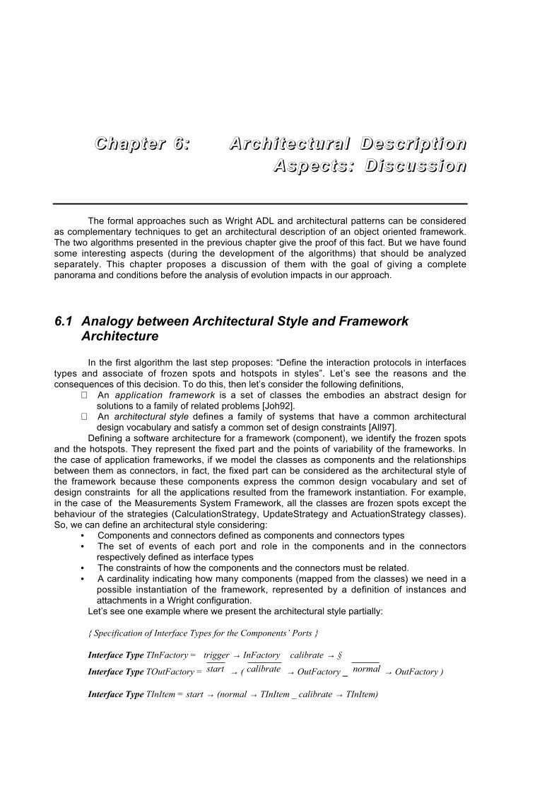
The formal approaches such as Wright ADL and architectural patterns can be consideredas complementary techniques to get an architectural description of an object oriented framework.The two algorithms presented in the previous chapter give the proof of this fact. But we have foundsome interesting aspects (during the development of the algorithms) that should be analyzedseparately. This chapter proposes a discussion of them with the goal of giving a completepanorama and conditions before the analysis of evolution impacts in our approach.
6.1 Analogy between Architectural Style and FrameworkArchitecture
In the first algorithm the last step proposes: “Define the interaction protocols in interfacestypes and associate of frozen spots and hotspots in styles”. Let’s see the reasons and theconsequences of this decision. To do this, then let’s consider the following definitions,
⇒ An application framework is a set of classes the embodies an abstract design forsolutions to a family of related problems [Joh92].
⇒ An architectural style defines a family of systems that have a common architecturaldesign vocabulary and satisfy a common set of design constraints [All97].
Defining a software architecture for a framework (component), we identify the frozen spotsand the hotspots. They represent the fixed part and the points of variability of the frameworks. Inthe case of application frameworks, if we model the classes as components and the relationshipsbetween them as connectors, in fact, the fixed part can be considered as the architectural style ofthe framework because these components express the common design vocabulary and set ofdesign constraints for all the applications resulted from the framework instantiation. For example,in the case of the Measurements System Framework, all the classes are frozen spots except thebehaviour of the strategies (CalculationStrategy, UpdateStrategy and ActuationStrategy classes).So, we can define an architectural style considering:
• Components and connectors defined as components and connectors types• The set of events of each port and role in the components and in the connectors
respectively defined as interface types• The constraints of how the components and the connectors must be related.• A cardinality indicating how many components (mapped from the classes) we need in a
possible instantiation of the framework, represented by a definition of instances andattachments in a Wright configuration.
Let’s see one example where we present the architectural style partially:
{ Specification of Interface Types for the Components’ Ports }
Interface Type TInFactory = trigger → InFactory calibrate → §
Interface Type TOutFactory = start → ( calibrate → OutFactory _ normal → OutFactory )
Interface Type TInItem = start → (normal → TInItem _ calibrate → TInItem)
CChhaapptteerr 66:: AArrcchh ii tt eecc ttuurraa ll DDeessccrr iipp tt iioonnAAssppeeccttss :: DDiissccuussss iioonn

Chapter 6: O. O. Architectural Description Aspects: Discussion 85
Interface Type TOutItem = culationperformCal → TOutItem _ calibrate → TOutItem
_ actuate→ TOutItem
Interface Type TIFactory = start → (calibrate → IFactory _ normal → IFactory)Interface Type TMitem = calibrate → Mitem _ start → (normal → MItem _ calibrate → Mitem)
{ Specification of Components }
Component Item_FactoryPort In = TInFactoryPort Out = TOutFactory
Computation = In.trigger → startOut. → ( calibrateOut. → Computation
_ normalOut. → Computation ) _ In.calibrate → Computation _ §
Component Measurement_ItemPort In = TInItemPort Out = TOutItem
Computation = In.start → ( In.calibrate→ culationperformCalOut. → calibrateOut.
In.normal→ culationperformCalOut. → actuateOut. )
→ Computation_ §
{ Specification of Connectors }
Connector IF_MIRole IFactory = TIFactoryRole Mitem = TMItem
Glue = IFactory.start → startMItem. → (IFactory.normal → normalMItem. → Glue
_ IFactory.calibrate → calibrateMItem. → Glue)
{ Specification of the Constraints }
Constraints
∃ factory : Components _ Type(factory) = IFactory ^ # factory = 1^ p: Ports | p _ Ports(factory)
_ Type(p) = TInFactory v Type(p) = TOutFactory
∃ item : Components _ Type(item) = Measurement_Item ^ # item = 1^ p: Ports | p _ Ports(item)
_ Type(p) = TInItem v Type(p) = TOutItem
∃ factory_item : Connectors _ Type(factory_item) = IF_MI ^ #factory_item =1^ r: Roles | r _ Roles(factory_item)
_ Type(r) = TIFactory v Type(r) = TItem
∀ r : Roles | r _ Roles(factory_item)

86 Object Oriented Architectural Description of Frameworks
∃ p1 : Ports | p1 _ Ports (Item_Factory) ( ( Item_Factory, p1 ), ( factory_item, r ) ) Attachments
^ ∃ p2 : Ports | p2 _ Ports (Item_Factory) ( ( Item_Factory, p2 ), ( factory_item, r ) ) Attachments
In the case of a framework component, as it is thought as a black-box entity, thearchitectural style will be used in the configuration of the system where the component will beused.
This approach of separating fixed from variable parts in an architecture is similar to aproposal made in [Mac00] and in [Neb98].
[Mac00] works with product families and they propose the existence of a referencearchitecture and a configuration architecture in product families architecture . The referencearchitecture describes the style upon which every product is built. It lists the rules for interaction ofthe various components, and the abstract framework that holds them together. A referencearchitecture may contain information, constraints and guidelines on the infraestructure that needsto be present in order to hold together the various components. This could mean the architecturalstructure, or the glue that holds the components together into the same system. Meanwhile, theconfiguration architecture is described for every product by the product configuration architecturedocument. In the case of several products that belong to the same family, a family configurationarchitecture document naturally springs from the combination of all member product configurationarchitecture documents.
An approach closer to the developed one in this dissertation is [Neb97] which proposestwo complementary notions of software architecture. They represent a separation of concernsrelating to the distinct nature of the information encompassed by each kind of architecture. Theinitial distinction is between classes and instances. A domain architecture consists of a set ofclasses (components) that are connected by potential relationships (connectors) between classesas expressed by its set of dependencies. The term domain reflects the fact that this notion ofarchitecture tells you how the model of your problem domain is structured. But a situationArchitecture consists of a set of instances (components) that are connected by the actualrelationships (connectors) between these instances. The term situation architecture reflects thefact that a situation architecture represents the structure of a particular concrete situation from theproblem domain as defined by a configuration of instance and their actual relationships. This is incontrast to a domain architecture, which represents potential relationships.The relationshipbetween a domain and situation architecture is one of instantiation. A situation architecture is aninstance of a domain architecture. The situation architecture’s components and connectors areinstances of the domain architecture’s components and connectors. Two kinds of architecture arecomplementary but they are fundamentally different. One way of thinking of the relationship is thatthe domain model defines what can and can not happen while a situation model defines, inconjunction with any input, what does and does not happen.
In our approach, the reference architecture [Mac00] and domain architecture [Neb98] couldbe compared to the definition of our architectural style of the framework, where we express whichthe classes (frozen spots: different aspects already implemented) are in all the applicationsresulting from the framework instantiation. In fact, in [Neb98], the mapping for relationshipsbetween classes are closer to our working level (code-level) and also a lower level of description
In our approach, we do not have a configuration architecture [Mac00] and situationarchitecture [Neb98]. In fact, we can think that this is similar to the configuration description madewith Wright ADL to represent an instantiation of a framework. In this case, we use the definedarchitectural style and we define the components and connectors that are specific to theinstantiation.

Chapter 6: O. O. Architectural Description Aspects: Discussion 87
6.2 Levels of Description
In both algorithms we propose an incremental process of the growth of the architecturaldescription starting from the first architecture obtained. There are two possible issues of growth:
• refinement (or grouping) of components getting microarchitectures and• replacement of a component (mapped from a class) by another one that represents a
refinement in the protocol of the component (a subclass).We consider that in fact, we have two dimensions of growth and each dimension generates
levels of description. If we consider both dimensions in X-Y axis, we can have a parameter tomeasure qualities of our design and/or implementation mapped to an architectural description.Supposing that we build a X-Y cartesian axis where (Figure 6.1):
• Y-axis gives information about how many architectural descriptions we have obtainedrefining (or grouping) components and connectors (r1, r2, … rn)
• X-axis gives information about how many changes in components and connectors(mapped from classes) we have made in our base architectural description (s1, s2, … sm)
(rn, s1)
r1
r2
r4
r5
rn
s1 s2 s3 s4 s5 sm
refinement
subclasses
(r1, sm)
Studied Area
Figure 6.1: Growth of the Architectural Description in X-Y axis
Let’s see then what kinds of evaluation we can make about our architectural description.An architectural description located in (sm, r1 ) indicates that we have a deep tree
representing hierarchy of classes and the absence of microarchitectures (grouping of classesrelated to fulfill a task). This can be a signal of ‘bad design’ caused by too many classes (related bya hierarchy) and few responsabilities in each subclass.
An architectural description located in (s1, rn ) indicates that we have a set of classes(without siblings in a hierarchy), each of them is an entry point for a microarchitecture. Here wehave different possibilities. If we are modelling a components’ framework, each refinementrepresented in the Y-axis will indicate a refinement in one different component each time. Thismeans that the framework is well-built because in those cases, the components are built as black-box entities and they are like microarchitectures that are adapted by the interface offered by thecomponent. But if we are modeling an application framework, the point (s1, rn ) in the diagramshows that we have a set of classes (very few because we are in the first step of growing in the X-axis) , and the classes have too many services each of them and several classes are dependent ofthe main classes (big microarchitectures). This can be a signal that the classes should be dividedwith different responsabilities in the classes which are the result.
We can also use the diagram to locate regions of what we consider a large or a smallframework in terms of amount of classes and microarchitectures. We can also decide which ofthese regions are better to determine a good balance of classes as lonely units and entrypoints tomicroarchitectures. In our case, we have studied a region limited by (s0, r0 ), (s0, r4,), (s5, r0 ) and
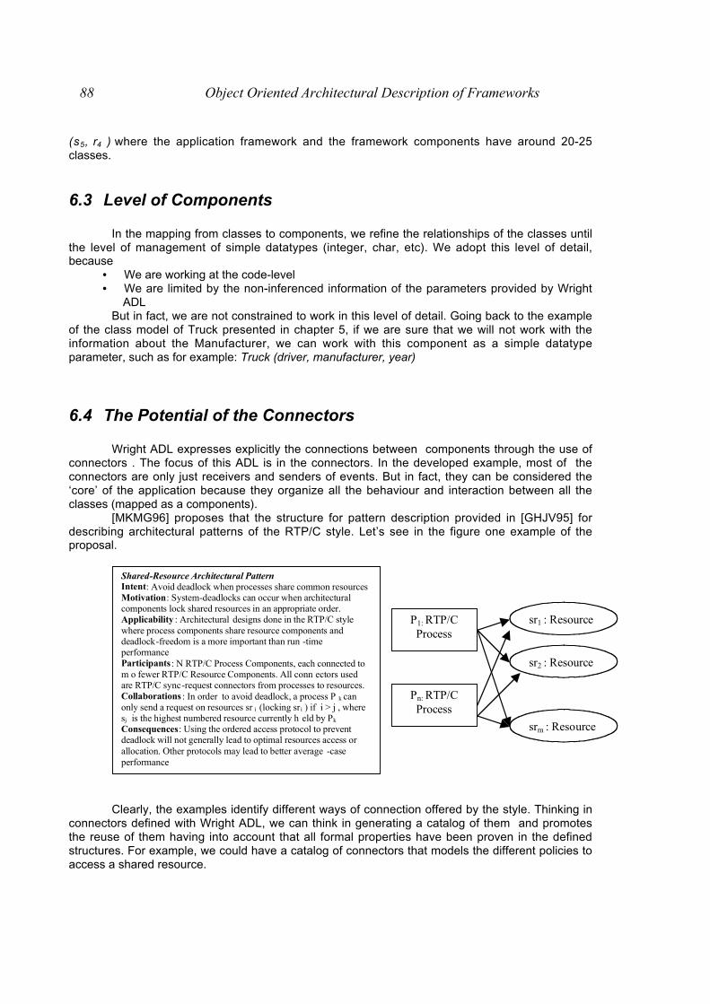
88 Object Oriented Architectural Description of Frameworks
(s5, r4 ) where the application framework and the framework components have around 20-25classes.
6.3 Level of Components
In the mapping from classes to components, we refine the relationships of the classes untilthe level of management of simple datatypes (integer, char, etc). We adopt this level of detail,because
• We are working at the code-level• We are limited by the non-inferenced information of the parameters provided by Wright
ADLBut in fact, we are not constrained to work in this level of detail. Going back to the example
of the class model of Truck presented in chapter 5, if we are sure that we will not work with theinformation about the Manufacturer, we can work with this component as a simple datatypeparameter, such as for example: Truck (driver, manufacturer, year)
6.4 The Potential of the Connectors
Wright ADL expresses explicitly the connections between components through the use ofconnectors . The focus of this ADL is in the connectors. In the developed example, most of theconnectors are only just receivers and senders of events. But in fact, they can be considered the‘core’ of the application because they organize all the behaviour and interaction between all theclasses (mapped as a components).
[MKMG96] proposes that the structure for pattern description provided in [GHJV95] fordescribing architectural patterns of the RTP/C style. Let’s see in the figure one example of theproposal.
Shared-Resource Architectural Pattern Intent: Avoid deadlock when processes share common resourcesMotivation: System-deadlocks can occur when architectural components lock shared resources in an appropriate order. Applicability : Architectural designs done in the RTP/C style where process components share resource components and deadlock-freedom is a more important than run -time performance Participants : N RTP/C Process Components, each connected to m o fewer RTP/C Resource Components. All conn ectors used are RTP/C sync-request connectors from processes to resources. Collaborations : In order to avoid deadlock, a process P k can only send a request on resources sr i (locking sri ) if i > j , where sj is the highest numbered resource currently h eld by Pk
Consequences: Using the ordered access protocol to prevent deadlock will not generally lead to optimal resources access or allocation. Other protocols may lead to better average -case performance
P1: RTP/C Process
Pn: RTP/C Process
srm : Resource
sr2 : Resource
sr1 : Resource
Clearly, the examples identify different ways of connection offered by the style. Thinking inconnectors defined with Wright ADL, we can think in generating a catalog of them and promotesthe reuse of them having into account that all formal properties have been proven in the definedstructures. For example, we could have a catalog of connectors that models the different policies toaccess a shared resource.

Chapter 6: O. O. Architectural Description Aspects: Discussion 89
6.5 Increment of Connectors and Components
In the first algorithm, we present two approaches: use of predefined styles and start fromthe “scratch” with the description. Comparing both approaches developed, we see clearly anincrement of the amount of components and connectors. But, in fact, the main idea points out torepresent close all the framework classes and their interaction. After the analysis of themicroarchitectures and styles inside the description, we can reduce this amount getting adescription according to our needs of description
6.6 Management of Errors
The static nature of the Wright ADL and the typed protocol makes us difficult addingmanagement of errors. The problem is focused that we must modify the protocol of the ports andcomputation, and this can provoke a great impact in all the description. In the case of modification,we can do it trying to focus the changes in the microarchitectures and also running the tool forchecking that our description is valid.
6.7 Lack of Expressiveness in Structural Features
The structural features can not be expressed. In both algorithms, we established that thedescription was composed of our classes mapped to the domain concepts. The hierarchyrelationship between two components can not be expressed explicitly, this means that we canchange a component by another one which adds behaviour to the first one (subclass relationship)but losing the idea of that one is subclass of the another one.
6.8 Lack of Expressiveness of Timing
The Wright ADL does not allow us express timing relationships. This means expressing aservice that is regulated by a timer, and that it is offered in regular time intervals. For example, thisrestriction can be seen when we work with the Measurement Systems Framework and werepresent PeriodicUpdate class (subclass of UpdateStrategy class) used by the Sensor class. Aninstance of this class has a cycle that indicates that after a set time interval, it must indicate to thesensor that it must update its information about the measurement item. We express thisrelationship is related as non-deterministic choice between the different behaviours of an instanceof UpdateStrategy class.
6.9 Dynamic Binding and Creation/Destruction of Components
The static nature of Wright ADL does not allow us to represent a dynamic binding of anobject in a body method and the creation and destruction of components in the description. Thefirst case can be illustrated with the example of ActuationStrategy in the method trigger in the ItemFactory class. In this method, an instance of a Measurement item is initialized and one of theinstance variables is an instance of Actuation Strategy class. This variable indicates if theinstantiated measurement item is in normal state (after having taken the measurements of thephysical item, the actuators are called) or in calibration state (after having taken the measurements

90 Object Oriented Architectural Description of Frameworks
of the physical item, the item is taken as the new prototype for the rest of the items). But thisbehaviour at run-time is seen when the actuation phase arrives, but in our description we had toexpress this difference when we modelled the initialization of the item.
Following with the same example, the factory initializes one item each time that a physicalitem enters in the physical system. Here, we should have a creation/destruction of instances, but inthe description we fix the relationship between these two classes and we simulate this process with
the event createcomponent. . But the notation should provide a way to express that this is a dynamic
relationship between the two components.
6.10 Detection of Errors with the Wright Checking Tool
The focus of our approach was the use of Wright checking tool as a secondary tool to ouralgorithms. The tool can assure us that the obtained description is valid. In case of an errordetection, while arguably one might attribute the detected problem to our specification, and not toframework, it does point out a place where the complexity of the specification can lead to errorsthat might be hard to detect otherwise. Without a precise model and effective automated analysistools to identify problem areas, errors could easily be introduced, undetected, into animplementation
6.11 Use and Discovering of Patterns in the ArchitecturalDescription
In both algorithms we propose the discovering of architectural and design patterns duringthe inference of the architectural description. We must note that we have different levels ofabstraction with patterns (from higher to smaller scale):
⇒ Architectural Patterns associated (or not) to architectural styles: Patterns andarchitectural styles are complementary mechanisms for encapsulating design expertise.As we said previously an architectural style provides a collection of building block designelements, rules and constraints for composing the building blocks, and tools foranalyzing and manipulating designs created in the style. Styles generally provideguidance and analysis for building a broad class of architectures in a specific domainwhereas patterns focus on solving smaller, more specific problems within a given style(or perhaps multiple styles) [Neb98]
⇒ Design Patterns: They are conceptual on a smaller scale than an individual architectureand numerous architectural patterns may be found in a single architecture. A designpattern is similar to a domain model in the sense that they both provide general solutionsto a class of a related problems; however, the major difference is that a pattern isgeneric and will occur across many otherwise unrelated domain architectures[MKMG96].
The studied frameworks and the inferenced description allowed us discover only a fewpatterns. The detection of an architectural pattern in a framework is a difficult task because all thedesign/implementation decisions were already made and the idea of applying one was notconsidered in the first design stages. The most applied is the Layered Architectural Pattern . Theparts are separated into layers by responsibility or service, the increased complexity associatedwith large applications become spread across those layers. By applying a divide-conquer approachto complexity, the total number of connections per part can be kept reasonable. Components, inturn, become more reusable and certainly more understandable.
Luckily we can detect an architectural pattern associated to an architectural style anddifferent design patterns to be joined to the generated architectural style at framework-level. Theinteresting issue about the detection of design patterns is to see how they can be represented with
Chapter 6: O. O. Architectural Description Aspects: Discussion 91
formal languages and thus, having another way of considering them, not just only informalsolutions to particular problems.
6.12 Properties of Cohesion and Coupling in the ArchitecturalDescription
[San97] proposes to evaluate the quality of the structure of an architecture introducing theconcept of cohesion and coupling. The cohesion of a component makes it possible to measure thequality of its structuring. A component should aim to fulfill only one logical function or logical entity.Thus, all the parts of a component must allow this goal. We thus calculate the degree of cohesionof a component compared to the parts of this component which contribute to its logical function (ifevery part do it, then the component will have a high degree of cohesion). In our approach, thecomponent are small (mapped from classes) and are not composed of other ones, but we makethe analysis of microarchitectures which comprises a set of classes that are gathered to fulfill atask of the framework.
[San97] thus defined seven levels of cohesion. We define them and mention if they can beanalyzed in our context
" Cohesion by coincidence: there are no relationships between the various parts of thecomponent, they are simply gathered in this component.
" Logical association: the components which carry out similar operations are gathered inonly one component.
" Temporal cohesion: all the components which are activated at the same time aregathered. Procedural cohesion: the elements of a component constitute only onesequence of control.
None of these kinds of cohesion appear in our description because the idea ofmicroarchitecture is to discover and join a set of classes related by a service that they must provideworking together. The microarchitecture is modelled with hierarchical composition [All97] of classeswhere the idea is to see the microarchitecture as a black box. We have an entrypoint for the inputand an entrypoint for the output usually represented by ports of components that are used as theinterfaces of the microarchitecture.
" Cohesion of communication: all the elements of a component operate on the same inputdata and produce the same output data.
This kind of cohesion does not appear in the microarchitecture because all thecomponents process the data producing different results, not necessarily related or of the sametype.
" Sequential cohesion: the output of an element of the component is used in input ofanother element.
This kind of cohesion is shown in the microarchitecture because the components in themicroarchitecture are connected and coordinated by the communication provided by theconnectors mostly in a sequenced way. Thus, they are data transformers in a sequential way.
" Functional cohesion: each part of the component is needed to do only one function.This kind of cohesion is expressed in the second developed algorithm. When we classify
the classes we do it analyzing what kind of services it provides. Thus we distinguish betweenprocessing, data, connecting, controller, coordinator, interface, service provider, information holderor structuring components.
" Cohesion of object: each operation offers a functionality based on the modification, theinspection or the use of the attributes of the object.
This kind of cohesion can be seen in each component and it appears when we replace thenon-deterministic choices by the use of an abstract machine B to show that the behaviour of acomponent is dependent of an internal state of the component.
Coupling, on the other hand, measures the interconnection between the various modulesof a system. It is recommended to have lowest coupling allowing a greater independence of the

92 Object Oriented Architectural Description of Frameworks
modules. In this case, we can evaluate the coupling at component-level, because we will take intoaccount the communication between them provided by the connectors.
[San97] again identified seven levels of coupling:" No direct coupling: two modules are without direct coupling if they correspond to two
modules without any link.This kind of coupling appears clearly in the description, because we only relate classes if
they have one of the three proposed relationships in the mapping. Given two classes A and B,instances of B can be instances/class variables of A; instances of B used as parameters in onemethod of A; or instances of B are connected to an instance of A by a dependency mechanism.
" Coupling by data: the system whose information is represented internally in thecomponents only communicate themselves by sending elementary data.
This kind of coupling appears in the description because Wright ADL does not allow usmake inferences over structures of data. Thus, we must work with elementary data.
" Coupling by structured data: This coupling is an alternative of the coupling by data. Thistime they are structures of data which are sent by a module interfaces.
As we explained previously, this kind of coupling does not appear in the description." Coupling of control: it is a well-known coupling in the design of architectures. This
coupling is observed when the internal execution of a module depends on the value of avariable called " flag " which is provided by another module.
This kind of coupling can be considered if we think that observing events in a componentare ‘flags’. Supposing this, when that event is executed in another component (in this secondcomponent it is an initiating event), this action shoots the starting process indicated by theobserving event.
" External coupling: the coupling happens when modules are bound by an externalenvironment with the software, for example, a communication protocol.
This kind of coupling is essential but must be limited to a restricted number of modules. Wecan say nothing about this kind of coupling because we focus our study to the internal parts of aframework and we do not find a framework with any external environment.
" Common coupling: the modules are rather independent from/to each other but havestrong interconnections by global variables.
This kind of coupling is not fullfilled by the architectural elements, because the protocolsdefined in the ports of the components are related to the protocols of the roles of the connectors.There is no independency among the components and the connectors that represents arelationship between classes. Besides this, there is no global data.
" Coupling by contents: this mode of coupling takes place when a module usesinformation of data or control kept internally in another module.
This kind of coupling exists in our architectural description but considering that thecommunication between the components is made through events and they can have parametersas data.
The considerable advantage to have strongly coherent components and slightly coupled isthat these components are well defined and independent. That thus enables us to more easilycarry out the maintenance and the reusability of a component.
6.13 Architectural Views
The goal of a software architecture is to address each concern in order to satisfy all theexpectations of the various stakeholders involved. With respect to this goal, a software architectureincorporates many different views of the system. These views are complementary and allow toimprove the understanding of the system showing various aspects of it [LC98]
A non-exhaustive list of the views which are more commonly developed can be found in[GCBA95]. Among them, we just keep the views which are possible to get with our approach:
Chapter 6: O. O. Architectural Description Aspects: Discussion 93
⇒ Structural/topological view : this view describes the components and the connections ofthe system and the topology of the connected set of components. Since this topologymay evolve dynamically, this view must show all the potential components andconnectors. This view is obvious, because a configuration of an architectural descriptionis a topological configuration in Wright ADL. The result is a topology of the classes andits interrelationships mapped as components and connectors respectively.
⇒ Behavioural view : this view describes the scheduling of system actions or system statetransitions. This view is reflected by coordination of events made by the connectors toorder the communication among the classes.
⇒ Growth view : this view describes maintainability, extensibility, adaptability, portability,scalability, and product line applicability of a system. This view can be seen when thearchitectural description grows through the modification/addition/grouping of componentsand connectors.
6.14 Complementariness with other Techniques
In the previous sections, we enumerate different problems and insufficiencies appearedusing the Wright ADL to get an architectural description of a framework (component): lack ofexpressiveness in structural features, lack of expressiveness of timing and no possibility to expressdynamic binding or creation/destruction of components. In fact, our approach is focused in usingthe formal approach given by an ADL to have a complementary technique to the existing ones. Themain idea is combine structural and behavioural software descriptions. The structure describeshow the different parts in a software system are arranged, and the behaviour of a system describesthe way in which it functions or operates. According to [SPL98], objects are dynamic entities,changing their state and behaviour throughout their existence. Object-oriented design models suchas UML (Unified Modelling Language) [UML], provide several diagrams for capturing the static anddynamic aspects of a particular domain. While object structure is often simple to model , objectbehaviour is extremely complex and requires numerous models to decompose the complexity.UML includes several diagrams for capturing the dynamic aspects of behavior, includingstatechart, activity, and interaction (sequence and collaboration) diagrams. The interactiondiagrams tend to be flow-oriented, depicting primarily interobject message flow (sequencediagrams) and data flow (collaboration diagrams). The statechart and activity diagrams focus onmodeling intra-object behavior, depicting the variations of behaviour an object exhibits during itslife (statechart diagrams) and the internal operations of a particular class method or operation(activity diagrams).
If we intend to make a parallel work between these techniques and our approach to inferarchitectural description, we show different aspects that can be complemented from both sides:informal and informal approaches. Let’s enumerate some possibilities.
The static aspects of the model can be described using the Wright ADL expressing theclasses and their relationships, but also building class hierarchies in parallel when we need tochange a class (mapped as a component) by a subclass (mapped as another component). Thus,we avoid to lose the idea of hierarchical relationship between the classes.
The object behaviour is localized in the port of a component. In fact, it is the same set ofmethods that appears in a class definition, but as they are classified in initiating/observing eventsin the architectural description, we know which services are initialized by the object and which onesthe object must wait to be notified by another object to start them. Thus, we also have a way ofcomplementing a class definition having extra information about the methods.
The computation part of a component also gives us local information about the sequenceof messages that are executed in the methods bodies of the object. This aspect is more oriented tointra-object information, but if we are interested to know the communication between two classesthat are not related directly, we should use collaboration diagrams. This notation offers us a way tosee a set of classes related by methods calls in a global overview. For example, the differentbehaviours of the subclasses of the UpdateStrategy class to notify the sensor when it should
94 Object Oriented Architectural Description of Frameworks
update its data were expressed in three different collaboration diagrams in the example shown inthe Appendix A. This is a limitation because a collaboration diagram is started by only onemessage and each possible variant in one communication between two classes changes thediagram. Anyway, this kind of diagram offers a good panorama of communication between a set ofclasses.
The statechart and activity diagrams focus also on intra-object information. The differentstates of an object and how they behave based on a set state are expressed in non-deterministicchoices using Wright ADL. Both techniques are complementary, one offers a visual idea and theother one offers the formal representation of the situation.
Another description technique that can be complemented by components described withWright ADL is CRC Cards. In the CRC cards a class is described informally detailing itsresponsibilities and its collaborators. As our approach defines a direct mapping from classes tocomponents/connectors, the CRC cards could add a section to represent the formal model of theclass specifying how the different responsibilities are carried out in the computation of thearchitectural element.
Examples can also find a formal perspective with architectural topologies described withWright ADL. Examples show particular functionalities of a framework through the use of a partialinstantiation. Restricting the set of events of the involved components to the example, we canprovide the topology corresponding to the particular instantiation
Summarizing, if we are interested in a complete description of a framework withcomplementary methodologies, we can consider the following viewpoints:
⇒ Global overview of the system structure: Components and Connectors⇒ Objects with structural features : UML diagrams (e.g. Composite Pattern)⇒ Interfaces of the objects : Port of the Components⇒ Localized behaviour: Component Description⇒ Relationship between two Objects (not necessarily connected in the Wright description):
Collaboration diagrams
6.15 Summary
This chapter presents some general aspects that show the flexibility and thecomplementariness of the studied approaches. We also enumerate some advantages anddisadvantages of using an ADL such as Wright: potential of the connectors, increment ofcomponents and connectors, management of errors, lack of expressiveness in timing andstructural features, the non-possibility of expressing creation-destruction of objects and processes,etc. Thus, we get first analysis before considering the evolution aspect. This is an important pointin which we are interested that can produce changes in the frameworks and we would like to seethe impacts in the inference architecture.
An object oriented framework is defined as a reusable design of all or part of a system thatis represented by a set of abstract classes and the way their instances interact or the skeleton ofan application that can be customized by an application developer. The second definitioncomprises the first one, because we consider that the skeleton of the application is the abstractclasses and the customization is the process of instantiation. Thus, the second definition gives themain feature of the framework: the customization of a design and code to get different applicationsin a specific domain. To get this level of a stable design and code, there was a developmentprocess that can be summarized with the following steps [Mat96]:
• Analysis of the problem domain• The first version of the framework is developed using the key abstractions found• One or possibly a few applications are developed based on the framework• Problems when using the framework in the development of the applications are captured
and solved in the next version of the framework• After repeating this cycle a number of times the framework has reached an acceptable
maturity level, and can be released for multiuser reuse in the organizationFollowing the approach of an iterative process, in chapter 5 we presented two algorithms
to get an architectural description of an object oriented framework or a framework component indifferent levels of abstraction (going from a general behaviour to specific behaviour). Thus, weobtained an “architectural vision” or an interaction architecture [Now99] that shows us how theframework or the component can be seen in a ‘high-level’ of abstraction, with:
• classes and interrelationships mapped as components and connectors• (in the second algorithm) assigning a semantic function to the classes in the framework.
Thus, we can have a classification of classes according to the kind of service that theyprovide, and not only a set of classes without any semantic relevance. For example, Policy class isa class which is in charged of policy access to a shared resource. In the studied model, this classis clearly mapped as a connector. However, not all the classes offer one single function. Thissituation happens mostly in object oriented frameworks already implemented (the case study of thefirst algorithm). In these cases, we adopt the idea of separating the internal state and the behaviourof the class in component and a connector. Thus, we focus the information on the component andall the management of communication in the connector.
But the requirements in the different domain applications can vary and it is necessary toupdate the framework to be able to instantiate it and cover all the new functions required. At thislevel, we talk about this phase as framework evolution. In this chapter we explain what are thepossible changes that a framework can have and how they affect to the architectural descriptionthat we proposed previously
7.1 General Overview of the Levels of Abstraction
During all the development of this dissertation, we have found that most of the literatureconsiders the view shown in the figure 7.1 to speak about different levels of abstractions. This viewis the original conception of a system, where a top-down methodology was applied to build asystem. Considering this viewpoint, from one perspective software evolution can take place atthree fundamentally different abstraction levels: the implementation level, the design level, and thearchitectural level. Depending on the characteristics and extent of an implementation change, itmay result in no major design changes, and thus no major architectural changes. However, it mayalso result in radical design and architectural changes. Changing the software design, may result in
CChhaapptteerr 77:: EEvvoolluutt iioonn ooff FFrraammeewwoorrkkss

96 Object Oriented Architectural Description of Frameworks
no major changes. For example, if the change can be realized simply by reorganizing parts of theold version in new version. Most likely however, a change to the design could also imply majorchanges on both the architectural and implementation level. Finally, a change of architecturetypically result in major changes of the design and implementation. In very special cases, we canimagine a change of architecture not resulting in major design and implementation changes.However, these must be considered exceptional cases.
Pattern and Styles I Pattern and Styles II
UML OO Model I UML OO Model II
Application I Application II
Architectural Design
Design
Implementation
Figure 7.1: Software Evolution at Three Levels of Abstraction
But the problem proposed in this dissertation is that once the system was built, thedocumentation of all the design decisions which can reflect the design and architectural level(proposed by [Now99]) is expressed informally and using the line-box diagrams. Thus the changesin the framework are very difficult to trace in the documentation. The final result is that the changesare only made in the code, new documentation is generated and we have versioning of theapplication and the documentation. Thus, detecting a change in the code implies to run tools overdifferent versions of the application and compare them to show the changing parts of theapplication. However, our proposal is based on a recovering an ‘architectural description’ of a builtobject oriented framework based on the design and code and use it as a documentation source forfuture changes . Our architectural description is very tied to the source code and so any changewill have an impact on it. Next subsection shows briefly a discussion of possible changes in aframework. Based on them, we search to see how to track the evolution issue, the use of rules toreflect the changes and evaluate the quality of the proposed architectural description.
7.2 Aspects of Evolution
Using object oriented frameworks as components and working in the software product-linearchitecture and the effect of new or changed products requirements, [Mat00a] identifies aclassification scheme of framework evolution. In fact, this proposal works in a coarser grained levelof components than one considered in this dissertation but the different features of evolution areapplied at framework level. Thus, we show the proposed categorization and analyze how thesechanges are (not) propagated in the architectural description proposed in the previous chapter.
7.2.1 Internal reorganization
In response to new requirements, the framework may be reorganized internally withoutaffecting the externally visible functionality of the framework. The reason for reorganization is toimprove one or more of the quality requirements (sometimes referred to an non-functionalrequirements) of the framework, e.g. flexibility, reusability or performance.
Hot spot introduction: The client of the framework has a possibility to use this new flexibility optionor rely on the original default behaviour. Introduction of a new hotspot generally improves theflexibility quality attribute of the product.

Chapter 7: Evolution of Frameworks 97
In application frameworks, we take only into account three possibilities [FPR00]:introduction of an abstract method in an existing class, introduction of a new class and introductionof a set of classes (microarchitectures).
Let’s see step by step how we must change our description in each case.Introduction of an abstract method in an existing class:
1. Transform the new method in a process2. Detect the component which represents the class.3. Add as parameter the method mapped as a process.4. Adapt the protocol of the component in the ports and in the computation with the new
process. This can mean add the process in the right position in the chain of execution.5. Change the roles of the connector that is affected by the previous change.6. If the change is located in the first levels of description, propagate the changes in the
successive descriptions
Introduction of a new abstract class1. Model the class as a component considering the behaviour as initiating/observing events
and transform the abstract method(s) in process(es).2. Detect the classes (and the respective components) affected by the relationship with
the new class.3. Modify the connectors with the new relationships and the new protocols.4. If necessary, modify the affected components. In some cases, the components can have
a new task based on the event of the new component.5. If the change is located in the first levels of description, propagate the changes in the
successive descriptions6. If we have subclasses of the affected component, we should try to test the change in the
different level of description considering this new subclass
Introduction of a new microarchitectureIn this case, we must run the first algorithm to build the new microarchitecture (including
following the suggested steps for modelling abstract methods or classes).Following the same steps for the introduction of a new abstract class (considering all the
microarchitectures as the new class) considering which are the entry points for themicroarchitecture.
Restructuring: It may be necessary to perform some framework restructuring using refactoringtechniques [Opd92] to comply to new requirements. An example of a possible refactoring istransforming a class hierarchy relationship into an aggregate relationship. These kinds oftransformations are behaviour preserving but result in a changed reuse interface of the framework.Restructuring is often used for achieving better maintainability of the framework and only affectsthe internal structure of the framework since the restructuring is behavior preserving.
Let’s see two of some examples of refactoring proposed in [DDN99] and how thesechanges can be shown in the architectural description. Most of them look for creation/modification/removal of a superclass/subclasses together with a number of pull-ups or push-downsof methods and attributes: Split into Superclass/Merge with Superclass, Split into Subclass/Mergewith Subclass, Move to other Class (Superclass, Subclass or Sibling Class), Split Method/FactorOut Functionality
Split into Superclass1. Detect the components which must be splitted.2. Classify the (set of) events that must be distributed in the new three components.3. Build the new three components with their respective protocols in the ports and the
computation.4. Detect the original connectors of the components.5. If necessary, build new connectors with the subset of events of the protocols.
98 Object Oriented Architectural Description of Frameworks
6. If the change is located in the first levels of description, propagate the changes in thesuccessive descriptions
Merge with Superclass1. Detect the components which must be merged.2. Classify the (set of) events that must be distributed in the two components, which will
have the final result.3. Build the two components adapting their respective protocols in the ports and the
computation.4. Detect the original connectors of the component to be removed.5. Adapt the connectors of the new two components with the new events.6. If the change is located in the first levels of description, propagate the changes in the
successive descriptions
Changing control flow: in cases where the order of actions in response to an event needs to bechanged, the flow of control between the objects in a framework needs to be changed. One mayargue whether this is a change in functionality, since the same behavior is executed, although in adifferent order.
This change in the architectural description is focused on the connectors, because theycoordinate the communication between the different classes mapped as components. So thechange of control flow is the change in the sequence of events in the glue of the connectors thatcommunicate the classes affected by this evolution issue. This aspect is not so critical, becausethe propagation in the different levels of description is just only the change of a protocol in aconnector
Refining framework concepts: The new requirements may point out flaws in the framework designsuch as classes that has two roles that now have to be refined further. This action will make theframework more understandable and it may provide new hot-spots to be added to the reuseinterface. Concept refining does not affect the internal behaviour but it does change the internalstructure of the framework.
This issue can be considered as a mixture of refactoring and introduction of hotspots.
7.2.2 Changing functionality
The functionality of the framework may need to be changed. For instance, due to newunderlying hardware the way the framework interacts with the hardware needs to be adapted. Thecalling interface and structure of the framework tend to remain constant, but the behavior inresponse to events is changed.
Changing the internal class behaviour : This behavioural change is localized to only one class inthe framework and the class affected has no complex behavioral relationships to other classes.
This aspect just only affects the definition of a class, thus, we must change the respectivecomponent in the architectural description, and also propagate the changes if the change is madein the first levels of description. In spite that the definition says ‘no complex behavioralrelationships’ , the relationships of the classes are mapped on the connectors and the ports andthe roles protocols are tied in a configuration definition through the attachments. Then we mustpropagate the change if some events are added or removed from the protocols definition in thecomponent.
Restructuring the subsystem: When extending the product family with new products, a typicalsituation is where a framework needs to provide different versions of a part of its behaviour.Assuming that no preparations were taken in the original framework design, the version-dependentfunctionality will often be spread out over the framework. This requires a restructuring and
Chapter 7: Evolution of Frameworks 99
partitioning of the framework’s behavior , generally leading to a division into two subsystems,containing version-independent and version-dependent behavior, respectively. The subsystemsare often organized in a layered or master-slave like structure.
In this case, we have a large impact in the framework because we need to restructure andpartition the complete framework to adapt them. This impact obviously affects the architecturaldescription too. We recommend to identify changes in microarchitectures and propagate them inthe architectural description to see gradually how the changes affect it. Another possibility is justgenerate all the changes and run the algorithms again, keeping as documentation the old and thenew versions of the architectural descriptions.
7.2.3 Extending functionality
A very common type of framework evolution is the extension of the framework functionality.Especially when adding new products to a product family, additional functionality may be requiredfrom one or more of the reusable frameworks.
Functionality introduction: new requirements may demand the extension of the frameworkfunctionality. If the architectural requirement only affects one framework, the situation is similar tothe traditional monolithic framework development process, which implies iterating the frameworkdesign for achieving a new framework version [Joh91] [Mat00b]. Our approach is focused on thearchitectural description of only one framework. Thus, the introduction of functionality can be seenas the introduction of a new microarchitecture and connect it to the existing classes. If so, we mustbuild the architectural description of the microarchitecture and we must detect the entrypoint of themicroarchitecture and which are the components and the connectors will be connected to the newpart of the framework. Thus we must modify the protocols of the components and the connectorsto adapt the new communication with the added michroarchitecture.
Concept introduction: The introduction of new concepts in the framework causes the introduction ofnew functionality. New concepts require the reorganization of the framework since new conceptshave relations to the existing concepts. Concept introduction often requires the use of earliermentioned techniques, e. g. concept requirement, hot-spot introduction, etc.
7.2.4 Reducing functionality
In certain cases, functionality that was developed as an integral part of the frameworkfunctionality has to be removed from the framework. For example, one possible cause includes theintroduction of a new specialized framework that requires the functionality it provides to beremoved from the other frameworks.
Enable/disable introduction: there may be product family requirements that require the introductionof an enable/disable mechanism in the framework. This type is evolution is not so commoncompared to the rest of the types of evolution taking into account that we work with smallframeworks. But the an enable/disable mechanism can be thought as the introduction of a newcomponent that has the responsibility of manage this, or just the modification of protocols of thecomponents and the connectors involved in the operation or simpler, the use of boolean variables.
In all the cases we must change (or create a new component and ) adapt roles and portsprotocols to reflect the new changes.
Cutting functionality: If new requirements for a product family require the use of an additionalframework that has to collaborate with the existing framework, conflicts due to of domain overlap orimplicit assumptions about ownership of the thread of control may occur (e.g. [MB00][SBC96]).This will make it necessary to cut functionality out of the existing framework component since it
100 Object Oriented Architectural Description of Frameworks
may be not possible to make necessary changes in the new framework, for instance, due to lack ofaccess of source code or the complexity.
Thus, to cut the functionality means the deletion of components and connectors. Thus, thisaction implies that firstly, we must detect which of the components are connected to the potential-non-existing components and check which are the events to be deleted in the affectedcomponents, and adapt the respective protocols with the reduced set of events.
7.3 Analysis
Except in the case of ‘change of control flow’, which is a change focalized in theconnectors, the rest of the evolution aspects causes many changes in our set of architecturaldescriptions (obtained with several runnings of our algorithms). If the changes are located in thefirst levels of description (general aspects) , it will also provoke a propagation in the rest of levels(specific aspects). But it is clear that this situation happens because, at the level where are working(close to code-level) and the size of object oriented frameworks are very small and our mappingrelates tightly a class to a combination of a component-connector. Thus, the format of a componentgives information about the class structure, the ports protocols says the functionality of the classand the connector shows how the different classes are related and how they collaborate to fulfil theservices provided by the framework. So if we reflect a change in the structure of classes, we haveclearly a change in a set of components and connectors (resulted from the mapping). In the bestcase, we localize a change in only one class and thus, a modification in component; but in theworst case, for example refactorings, the changes at structural level are deep in the architectureand must be propagated in all the levels of description. If we reflect a change in the functionality ofclasses, the changes are localized in the computation and glue protocols, where all the classesbehaviour is expressed.
Considering that" We are working at a low level of abstraction (code-level)" An evolution in the framework changes the structure/functionality of the architectural
description proposed by the dissertation" We propagate the changes from the more generic to specific behaviour in the
architectural description, because we are interested in keeping all the ‘process of growth’as a documentation of the framework, complemented by other methodologies.
an evolution analysis helps to:⇒ Gain an overview of the system evolution⇒ Qualify the parts of the system in terms of their stability over the versions⇒ Identify system components which could be reused in other systems⇒ Identify the migration of components between systems parts, and⇒ Identify components that have appeared or disappeared over the life-cycle of the system⇒ Isolate the different ‘regions’ of the frameworks that change very often and thus
recognise the level of criticality of the different parts of the framework.
7.4 Summary
Based on scheme about framework evolution, this chapter summarizes the different typesof changes that a framework can have. We also provide a brief analysis in each case that showsus what kinds of changes are made in the architectural description.
8.1 Context
In the research described in this thesis we have investigated the applicability of formalapproaches of software architectures (such as Wright ADL and architectural patterns) to get anarchitectural description of object oriented frameworks, and also analyze the impacts of evolutionissues in the inferred framework architecture.
To fullfil with these requirements, firstly we start to study all the features of softwarearchitectures, architectural styles and patterns, and ADLs. Thus, we discovered that the mostsystems where these concepts are applied were not concerned with the object oriented paradigm.This means that the systems were not designed using an object oriented methodology norlanguage. In this context the use of ADLs was concentrated in recovering the properties of thesesystems and mapped them in an architecture. If the resulting architecture could comprise classicalarchitectural styles (such as pipes and filters, layers, etc), this would include the ‘added values’ ofproperties of these styles.
Secondly, we investigated the characteristics of object oriented frameworks in general andwe concentrated our analysis in application and components frameworks and how the informaldocumentation techniques describe what are the services provided by the frameworks and what isrequired to instantiate it for some application, for example. In this field, we found differentapproaches. Most of them were guided by a similar idea presented in this thesis: the combinationand complement of several artifacts of domain analysis and object oriented design to give differentviews of a framework’s architecture. Among these techniques we can mention usage scenarios,examples, patterns and contracts. But, one critical issue of these artifacts is that they do not allowus to make any inference about the formal properties about the framework that they describebecause the semantics of the parts are lost in box-line drawings, and thus, we do not haveinformation about design decisions taken during the building process and use of the framework. Toget them, in the worst case, we must understand the framework at code-level.
Finally, we developed the approach presented in this dissertation. It comprises of amapping from Java/Smalltalk code to CSP-notation and two algorithms that allows to get anarchitectural description expressed in components and connectors with Wright ADL andarchitectural patterns as a complement. This work was made in three stages. The first one was ananalysis of the common points between software architectures and object oriented frameworks tofind the gaps that we had to fill to fulfill the objective. Based on the first stage, the second oneconsisted in the definition of the artifacts (proposed in this thesis) and the applicability of them intwo of all the studied cases. In that, the approach was more understandable and easy to follow.The third step was comprised of a posterior analysis of the strengths and weaknesses of ourapproach and also a discussion of impacts of change when the framework evolves.
Following we present the conclusions of our approach and some open research issues thatwere generated during the development of this work.
CChhaapptteerr 88:: CCoonncc lluuss iioonnss aanndd FFuuttuurreeRR ee ss ee aa rr cc hh
102 Object Oriented Architectural Description of Frameworks
8.2 Conclusions
The lack of established rules to define how we can inference an architecture from anapplication in general and the treatment of software architectures in a ‘high level of abstraction’made us to define the constraints of our work context. Therefore, we restrict the use of the termarchitecture to the semantic structure of an application, a static notion of software architecture, andwe consider that what was important was to understand how the classes in a framework wererelated structurally and what the consequences of this structure are on the software system.Classes seldom perform useful behaviour by themselves; they often contribute to a given functionby interacting with other objects. We focus our work on a lowest or base-level notion of softwarearchitecture that reflects the semantic structure of a software system: the code-level combined withinformation about design-level in object oriented frameworks.
Starting from the code and design of an object oriented framework where the informationabout semantic structure was almost hidden, we get an architectural description with the followingcharacteristics:
" The classes mapped as a combination of a component and a connector allows us toobtain two models: units of computation (components) and units of communication(connectors). Thus, we separate and localize the internal state of the class from theinformation about which classes are connected with.
" The model of communication (set of connectors) provides us all the behaviour thatappeared in the framework and makes us explicit the ordering method calls and theprotocol of interaction between the different classes.
" A classification of the messages inside a class: Using the concept of initiating andobserving events of Wright ADL, we were able to know which messages weredependent only of the class and which ones were called by other classes.
" We provide levels of abstraction that gives us the architecture from a generic to specificview of the different parts of the framework.
" The detection of microarchitectures encapsulating them in a hierarchical descriptionprovided by Wright ADL.
Through the use of architectural styles we expressed the fixed parts of a framework(hotspots). Therefore we got a formal model that characterizes all the applications resulting fromthe framework instantiation.
About the mapping, we obtained a language-independent definition to transform statementsto CSP-notation. The considered statements are also present in procedure oriented languages, notonly in object-oriented ones, thus it can be useful to infer information about application generatedin those languages.
The run of the algorithm getting a sequence of architectural description gave us a parameterto measure different qualities of the framework.
One of the most important points is that the developed description technique can be used asa complement with existing ones, because this is a way of providing the ‘bridge’ between informaland formal approaches.
However, during the use of Wright ADL as our main tool we found different problems:" The static nature of this language made us difficult to add a management of errors. To
do this we must change the interaction protocol of the components and connectors andwe lose the expressiveness of the protocols because the behaviour and the errorsmessages are mixed
" The hierarchical relationship between two classes is not explicit in the description. If wechange a component from one level of description to another one, and the lattercomponent represented a subclass of the class mapped as the first component, thisrelationship is lost.
" The dynamic binding is expressed as two possibilities using non-deterministic choice.This fact is related as the absence of this ability in the ADL.
Chapter 8: Conclusions and Future Work103
8.3 Future Research
An automatic tool to make the mapping and to run the algorithms would help us to validatethis approach and to evaluate object oriented framework larger than we presented here.
An analysis of the information that can provides us the test of formal properties given byWright ADL. In fact, the verification of the formal properties using the Wright tool was only used asa way of verification if the built model was a valid description. But, we think that it is useful to studywhat other information we can obtain from this verification.
The possibility of working in a higher level using all the architecture obtained through theuse of algorithms, focusing on the actual tendency of software.
We do not handle important issues such as performance, reliability, and security. For manyframeworks finding notations that expose such properties can be useful.
The formal model is essentially flat. To come up with this problem, our model we proposeto work in different dimensions and levels of description (from general to specific behaviour). Itwould have been much nicer to be able to mirror the inheritance structure in the architecturalspecification.
A formal representation of design patterns: in the case of component framework proposedby [CTN97], they apply a good principle of composition. They got adaptable components as black-box entities that provide a solution to coordination problems. One of the components encapsulatesthe Acceptor-Connector Pattern which provides a communication service. Based on this idea, it isinteresting to explore which design patterns can be encapsulated as a component with plugs andwe could generate a formal representation of it. Thus we would have not only the solution offeredby the design pattern but also a formal representation with classical properties checked by theWright tool.
Finally, it would be interesting to extend this work with ADL which allows dynamicarchitectures (where components appear and disappear, or where the topology of a configurationchanges during an execution): such as PICCOLA, - π -Space, dynamic Wright. Some languagesmay include all potential elements in the system description, and then ignore those that do notcurrently exist. Others , however, describe each possible configuration as a different architecture
References
[AAG93] G. D. Abowd, R. Allen, and D. Garlan. Using style to understand descriptions of softwarearchitectures. ACM SIGSOFT Software Engineering Notes, 18(5):9-20, December 1993
[Abr96] J-R. Abrial. The B Book. Cambridge University Press, 1996[Ada95] D. Adair. Building Object-Oriented Frameworks, AIXpert, February-May 1995[AG94] R. Allen and D. Garlan. Formalizing architectural connection. In Proceedings 16th
International Conference on Software Engineering, pp. 71-80. IEEE Computer SocietyPress / ACM Press, 1994
[AG96] R. Allen and D. Garlan. A Case Study in Architectural Modelling: The AEGIS System. InProceedings of 8th International Conference on Software Specification and Design(IWSSD-8), March 1996
[AGI98] R. Allen, D. Garlan, and J. Ivers. Formal modeling and analysis of the HLA componentintegration standard. ACM SIGSOFT Software Engineering Notes, 23(6): 70-79,November 1998. Proceedings of the ACM SIGSOFT Sixth International Symposium onthe Foundations of Software Engineering
[Ale76] C. Alexander. The Timeless Way of Building. New York: Oxford University Press. 1976.[All97] R. Allen. A Formal Approach to Software Architecture. Ph. D. Thesis, School of
Computer Science, Carnegie Mellon University, Pittsburgh, May 1997[And94] G. Andert. Object Frameworks in the Taligent OS. Proceedings of Compcon 94, IEEE
CS Press. Los Alamitos. California. 1994[Ber98] L. Bergmans. A Notation For Describing Conceptual Software Architectures. In
Proceedings of the First Nordic Software Architecture Workshop (NOSA'98). University of Karlskrona/Ronneby. August, 1998
[BGK+97] D. Baumer , G. Gryczan, R. Knol, C. Lilienthal, D. Riehle and H. ZullinghovenCommunications of the ACM, 40(10): 52-59, October 1997
[BJ94] K. Beck, R. Johnson. Patterns generate Architectures. In Proceedings of the 8th
European Conference on Object Oriented Programming. Bologna. Italy. 1994[BMR+96] F. Buschmann, R. Meunier, H. Rohnert, P. Sommerland, and M. Stal. A System of
Patterns – Pattern Oriented Software Architecture. Wiley, 1996[Bos00] J. Bosch. Measurements Systems Frameworks. In Domain Specific Application
Frameworks: Frameworks Experience by Industry. M. Fayad, R. Johnson editors, WileyPress, 2000
[BR96] T. Biggerstaff and C. Richter. Reusability framework, assessment , and directions. IEEESoftware 4(2): 41-49, March 1996
[Bro00] L. Bross. Box Structures as an ADL. Master Thesis to appear. University of SouthFlorida, 2000. http://home.tampabay.rr.com/adls/archben.html
[CDK94] G. Coulouris, J. Dollimore and Tim Kindberg. Distributed Systems Concepts and Design.Addison Wesley, 1994
[CES85] E. M. Clarke, E. A. Emerson, and A. P. Sistla. Automatic verification of finite stateconcurrent systems using temporal logic specifications. Technical report, Austin, 1985
[CTN97] J. C. Cruz, S. Tichelaar and O. Nierstrasz. A Coordination Component Framework forOpen Systems. In Proceedings of COORDINATION ’97, 1997
[Deu89] L . P. Deutsch. Design Reuse and Frameworks in the Smalltalk-80 system. In SoftwareResusability, Vol II, T. J. Biggerstaff and A. J. Perlis, editors . ACM Press, 1989
[DDN99] S. Demeyer, S. Ducasse and O. Niertrasz. Finding Refactoring via Change Metrics.Proceedings of OOPSLA 99. 1999
[DMNS97] S. Demeyer, T. D. Meijler, O. Nierstrasz, and P. Steyaert. Design guidelines fortailorable frameworks. Communications of the ACM, 40(10): 60-64, October 1997
[FPR00] M. Fontoura, W. Pree and B. Lumpe. UML-F: A Modeling Language for Object-OrientedFrameworks. In Lecture Notes in Computer Science Nr. 1850 Proceedings of ECOOP2000 Elisa Bertino (ed.) Springer-Verlag. June 2000.
[FSJ00] M. Fayad, D. Schmidt, and R. Johnson. Application Frameworks. In Building Application

References 105
Frameworks: Object Oriented Foundations of Framework Design. M. Fayad, D. Schmidt,and R. Johnson (editors). Wiley Press. 2000
[GA094] D. Garlan, R. Allen, and J. Ockerbloom. Exploiting style in architectural designenvironments. In Proceedings of SIGSOFT ’94: The Second ACM SIGSOFTSymposium 1994 on the Foundations of Software Engineering, December 1994
[GAO95] D. Garlan, R. Allen, and J. Ockerbloom. Architectural mismatch: Why reuse is so hard.IEEE Software, 12(6): 17-26, November 1995
[Gar95] D. Garlan. What is Style ? In Proc. First International Workshop Software Architecture,April 1995
[GCBA95] C. Gacek, B. Clark, B. Boehm, and A. Abd-AllAh. On the definition of software systemarchitecture. In Proceedings of the 1st International Workshop on Architecture forSoftware Systems, pp. 85-94, Seattle, WA, April 1995
[GHJV95] E. Gamma, R. Helm, R. Johnson, and J. Vlissides. Design Patterns: Elements ofReusable Object-Oriented Design. Addison Wesley, 1995
[GMW97] D. Garlan, R. Monroe, D. Wile: ACME, An Architecture Description InterchangeLanguage, White-paper, 1997
[Gol84] A. Goldberg. Smalltalk-80: The Interactive Programming Environment. Reading MA:Addison-Wesley. 1984
[GP94] D. Garlan and D. Perry. Software architecture: Practice, potential and pitfalls. InProceedings: 16th International Conference on Software Engineering, pp. 363-364. IEEEComputer Society Press / ACM Press, 1994
[GP95] D. Garlan and Dewayne Perry. Introduction to the Special Issue on SoftwareArchitecture. IEEE Transactions on Software Engineering, 21(4): 269-274, April 1995
[GS92] D. Garlan and M. Shaw. An introduction to software architecture. In Advances inSoftware Engineering and Knowledge Engineering, pp. 1-40, V. Ambriola and G. TortoraEditors. World Scientific Publishing Co. , 1992
[HJE95] H. Hueni , R. Johnson and R. Engel. A Framework for Network Protocol Software.Proceedings of OOPSLA 95, Austin, Texas. October 1995
[Hoa85] C. A. R. Hoare. Communicating Sequential Programming. Prentice Hall, 1991[Hol90] G. J. Holzmann. Design and Validation of Computer Protocols. Prentice Hall, 1990[HR94] F. Hayes-Roth. Architecture-based acquisition and development of software: Guidelines
and recommendations from the ARPA domain-specific software architecture (DSSA)program. Technical Report, Teknowledge Federal Systems, Palo Alto, CA, October1994
[Joh88] R. Johnson, B. Foote. Designing Reusable Classes, Journal of Object-OrientedProgramming, Vol .1, No. 2, June 1992
[Joh91] R. Johnson. Reusing Object Oriented Design, University of Illinois, Technical ReportUIUCDCS 91-1696, 1991
[Joh92] R. Johnson. Documenting frameworks using patterns. ACM SIGSOFT Notices, 27(10):63-76, October 1992. OOPSLA ’92 Proceedings, Andreas Paepcke (editor)
[Joh93] R. Johnson. How to Design Frameworks, Tutorial Notes, 8th Conference on Object-Oriented Programming Systems, Languages and Applications, Washington, USA, 1993
[KP88] G. Krasner and S. Pope. A cookbook for using the MVC user interface paradigm inSmalltalk-80. Journal of Objecrt Oriented Programming 1(3):26-49. September 1988
[LC98] P. Lalanda and S. Cherki. Object oriented methods and software architectures. PositionPaper in ECOOP 98, Workshop on Object Oriented Software Architecture. 1998
[LK94] R. Lajoie and R. Keller. Design and reuse in object-oriented frameworks: Patterns,contracts, and motifs in concert. In Proceedings of the 62nd Congress of the AssociationCanadienne Française pour l’Avancement des Sciences (ACFAS), Montreal, Canada,May 1994.
[LKA+95] D. Luckham, J. Kenney, L. Augustin, J. Vera, D. Bryan, and W. Mann. Specification andanalysis of system architecture using Rapide. IEEE Transactions on SoftwareEngineering, 21(4): 336-355, April 1995
[LT89] N. A. Lynch and M. R. Tuttle. An introduction to input/output automata. CWI Quarterly,2(3): 219-246, 1989
106 Object Oriented Architectural Description of Frameworks
[LV95] D. Luckham and J. Vera. An event-based architecture definition language. IEEETransactions on Software Engineering, 21(9): 717-734, September 1995
[Mat96] M. Mattson. Object Oriented Frameworks: a survey of methodological issues. LicentiateThesis, Department of Computer Science, Lund University,1996
[Mac00] A. Maccari. Architectural Evolution of product families. Position Paper in ECOOP 2000Workshop on Architectural Evolution. Cannes . 2000
[Matt00a] M. Mattsson. Object oriented Frameworks as Components – Experiences of FrameworkEvolution. Position Paper in ECOOP 2000 Workshop on Architectural Evolution. Cannes. 2000
[Matt00b] M. Mattson. Evolution and Composition of Object-Oriented Frameworks. PhD Thesis.Department of Software Engineering and Computer Science. University ofKarlskrona/Ronneby. 2000
[MB00] M. Mattsson and J. Bosch. Object oriented frameworks: Composition problems, causesand, solutions. In Building Application Frameworks: Object-Oriented Foundations ofFramework Design, pp. 467-487, M. Fayad, D. Schmidt, R. Johnson editors, WileyPress, 2000
[MDEK95] J. Magee, N. Dulay, S. Eisenbach, and J. Kramer. Specifying distributed softwarearchitectures, Lecture Notes in Computer Science, 989, 1995
[Men00] K. Mens. Automating architectural conformance checking by means of logic metaprogramming. PhD Thesis. Vrije Universiteit Brussel. June 2000
[MK96] J. Magee and J. Kramer. Dynamic structure in software architecture. In Proceedings of4th ACM SIGSOFT Symposium on the Foundations of Software Engineering (FSE 4),SEN, Vol.21, No.6, pp. 3-14, New York, October 1996. ACM Press
[MKMG96] R. T. Monroe, D. Kompanek, R. Melton, and D. Garlan. Stylized Architecture, DesignPatterns, and Objects. IEEE Software, Jan 1997, pp. 43-52
[MN95] T. D. Meijler and O. Nierstrasz, Beyond Objects: Components, Cooperative InformationSystems: Current Trends and Directions, M.P. Papazoglou and G. Schlageter (Eds.), pp.49-78, Academic Press, November 1995
[MORT96] N. Medvidovic, P. Oreizy, J. Robbins, and R. Taylor. Using object-oriented typing tosupport architectural design in the C2 style. ACM SIGSOFT Software EngineeringNotes, 21(6): 24-32, November 1996
[MQR95] M. Moriconi, X. Qian, and R. A. Riemenschneider. Correct architecture refinement. IEEETransactions on Software Engineering, 21(4): 356-372, April 1995
[MT97] N. Medvidovic and R. Taylor. A framework for classifying and comparing architecturedescription languages. In Proceedings of the Sixth European Software EngineeringConference (ESEC/FSE 97), pp. 60-76, Lecture Notes in Computer Science Nr. 1013,Springer-Verlag, September 1997
[MTW96] N. Medvidovic, R. N.Taylor, and E. J. Whitehead, Jr. Formal modeling of softwarearchitectures at multiple levels of abstraction. In Proceedings of the California SoftwareSymposium, pp. 28-40, 1996
[Neb98] R. Nebbe. Semantic Structure: A Basis for Software Architecture. In Proceedings of theECOOP ’98 Workshop on Object-Oriented Software Architectures, Lecture Notes inComputer Science Nr. 1543, J. Bosch and S. Demeyer editors. Springer-Verlag, 1998
[Now99] P. Nowack. Interacting Components – A Conceptual Architecture Model. Position Paperin ECOOP 99 Workshop on Architectural Evolution. Lisbon . 1999
[Opd92] W. F. Opdyke. Refactoring Object-Oriented Frameworks. PhD Thesis. University ofIllinois at Urbana-Champaign. 1992
[Pet77] J. L. Peterson. Petri nets. ACM Computing Surveys, 9(3): 223-252, September 1977.[Pre95] W. Pree. Design Patterns for Object-Oriented Software Development. Reading, MA:
Addision-Wesley, 1995[PW92] D. E. Perry and A. L. Wolf. Foundations for the study of software architecture. ACM
SIGSOFT Software Engineering Notes, 17(4): 40-52, October 1992[Ric98] T. Richner. Describing framework architectures: more than Design Patterns. In
Proceedings of the ECOOP ’98 Workshop on Object-Oriented Software Architectures,Lecture Notes in Computer Science Nr. 1543, J. Bosch and S. Demeyer editors.
References 107
Springer-Verlag, 1998[RJFC94] F. C. Ribeiro Justo and P. R. Freire Cunha. Deadlock-free configuration programming. In
Proceedings of the 2nd International Workshop on Configurable Distributed Systems,March 1994
[San97] R. Sanlaville. Description d’architecture logicielles: Utilisation du formalisme Wright pourl’interconnexion de machines abstraites B. Report for DEA d’Informatique: Systems etCommunications. Laboratoire LSR (Logiciels, Systèmes, Réseaux). Université JosephFourier. Grenoble. France. 1997
[Sch95] H. Scmid. Creating the Architecture of a Manufacturing Framework by Design Patterns.In Proceedings of the 10th Conference on Object-Oriented Programming Systems,Languages and Applications Conference, Austin, USA, 1995
[SBC96] S. Sparks, K. Benner, C. Faris. Managing Object-Oriented Framework Reuse. IEEEComputer. pp. 53-61. September, 1996
[SDK+95] M. Shaw, R. DeLine, D. V. Klein, T. L. Ross, D. M. Young, and G. Zelesnik. Abstractionsfor software and architecture and tools to support them. IEEE Transactions on SoftwareEngineering, April 1995
[SG96] M. Shaw and D. Garlan. Software Architecture: Perspectives on an Emerging Discipline.Prentice-Hall, 1996
[SG99] J. P. Sousa and D. Garlan. Formal modeling of the enterprise JavaBeans componentintegration framework. In Proceedings of FM ’99, Lecture Notes in Computer Science1079, Toulose, France, September 1999. Springer-Verlag
[SPL98] L. Seiter, J. Palsberg, K. Lieberherr: Evolution of Object Behavior Using ContextRelations. IEEE Transactions on Software Engineering, 24(1): pp. 79-92 (1998)
[Szy98] C. Szyperski. Component Software: Beyond Ojbect-Oriented Programming. Addison-Wesley and ACM Press. New York, NY, 1998
[Tal94] Taligent Inc. Building Object-Oriented Frameworks. A Taligent White Paper, 1994[TLPD95] A. Terry, R. London, G. Papanogopoulos, and M. Devito. The ARDEC/Teknowledge
architecture description language. Technical report, Teknowledge Federal Systems,1995
[Tra93] W. Tracz. Parameterized programming in LILEANNA. Proceedings of the ACM/SIGAPPSymposium on Applied Computing, pp. 77-86, E. Keaton, K. M. George, H. Berghel, andG. Hedrick editors, Indianapolis, February 1993, ACM Press.
[UML] Rational Rose. UML Notation Guide Version 1.1. September 1997.http://www.rational.com/UML
[Ves96] S. Vestal. MetaH Programmer’s manual, 1996[WBJ90] R. Wirfs-Brock , and R. Johnson. Surveying current research in object-oriented design.
Communications of the ACM 33(9): 104-124, 1990

Appendix A
This appendix shows a complete analysis of the Application of Wright ArchitecturalDescription Language to describe a Framework. The objective is to see an step-by-step process ofhow to get an architectural description using this ADL
BRIEF DESCRIPTION OF THE MEASUREMENT SYSTEMS
Measurement systems are a class of systems to measure the relevant values of a processor product. It is used for quality control of parts entering production or of produced products thatcan then be used to separate acceptable from unacceptable items to categorize the products inquality categories.
A measurement system consists of more than sensors and actuators. A typicalmeasurement cycle starts with a trigger, indicating that a product, or a measurement item, isentering the system. The first step after the trigger is the data collection phase performed by thesensors. The sensors measure the relevant variables of the measurment item. The second step isthe analysis phase, during which the data from the sensors is collected in a central representationand transformed until it appears in a form in which it can be compared to the ideal values. Basedon this comparison, certain discrepancies can be deduced, which in turn, lead to a classification ofthe measurement item and is used to perform associated actions, such as rejecting the item, whichcauses the actuators to remove the item from the conveyer belt and put it in a separate store, or toprint the classification on the item so that it can be automatically recognized at a larger stage.
One of the requirements for the analysis phase is that the way the transformation takesplace, the characteristics on which each classification should be flexible and easily adaptableduring system construction, but also, to some extent during the actual system operation.
ARCHITECTURE OF THE SYSTEM
[Bos00] identifies five entities that communicate with each other to achieve the requiredfunctionality• The trigger triggers the abstract factory when a physical item enters the system• The abstract factory creates representation of the physical object in the software, that is, the
measurement item.• The measurement item requests the sensor to measure the physical object• The sensor sends back the result to the measurement item that stores the results• After collecting the required data, the measurement item compares the measured values with
the ideal values.• The measurment item sends a message to the actuator requesting the actuation appropriate
for the measured data.
The necessary details about the design and the implementation of the framework will bedescribed later in order to understand the different decisions made in the architecture description.
After a first analysis made starting from the design documents [Bos00], it is possible toidentify the following components: Trigger, Item Factory, Measurement Item, Measurement Values,Sensor and Actuator. We identified the same entities as the author, but we added also theMeasurement Value because this component has an active interaction with Measurement Item.
So far, the described components are the main part of the Measurement Systemssoftware, because in the most of the systems, a substantial part is hardware, since the system isconnected to the real world through a number of sensors and actuators.Then we added thefollowing components Physical Trigger, Physical Sensor, Physical Actuator
The figure 1 shows the studied architecture

References 109
FIRST LEVEL
In this proposal, if the component A communicates with the component B through theevent m, one of the ports of the A will be called as B. Thus, in some way, we keep close to theimplementation, because if an event in the computation has the following format
B.m is similar to a structure object messageB.m!x is similar to a structure object message (parameters)B.m?x is similar to a structure x _ object messageB.m!x?y is similar to a structure y _ object message (parameters)
About the connectors roles, we will use the classnames that are connected by theconnector
ANALYSIS
Based on the previous ideas, we will start an analysis of all the architecture following theprocess and identifying the participants and their interactions.
1. The trigger triggers the abstract factory when a physical item enters the system
Components : Physical Trigger, Trigger and the Abstract Factory.Action: When a physical item enters the system, the physical trigger detects the entry and sends asignal to the trigger in the system. Then, the trigger triggers the abstract factory.
Component C_Physical_TriggerPort Out = T_Trigger_Out
Computation = triggerOut. → Computation _ closeOut. → §
Component C_TriggerPort In = T_Trigger_InPort Item_Factory = T_Trigger_Out_
Computation = In.trigger → triggerFactoryItem ._ → Computation
_ In.close → closeFactoryItem ._ → §
Component C_Item_Factory
CCoommppoonneennttss SSppeecc ii ff ii ccaa tt iioonn
Sensor
Actuator
MeasurementItem
AbstractFactory
Trigger
16
5
4
32
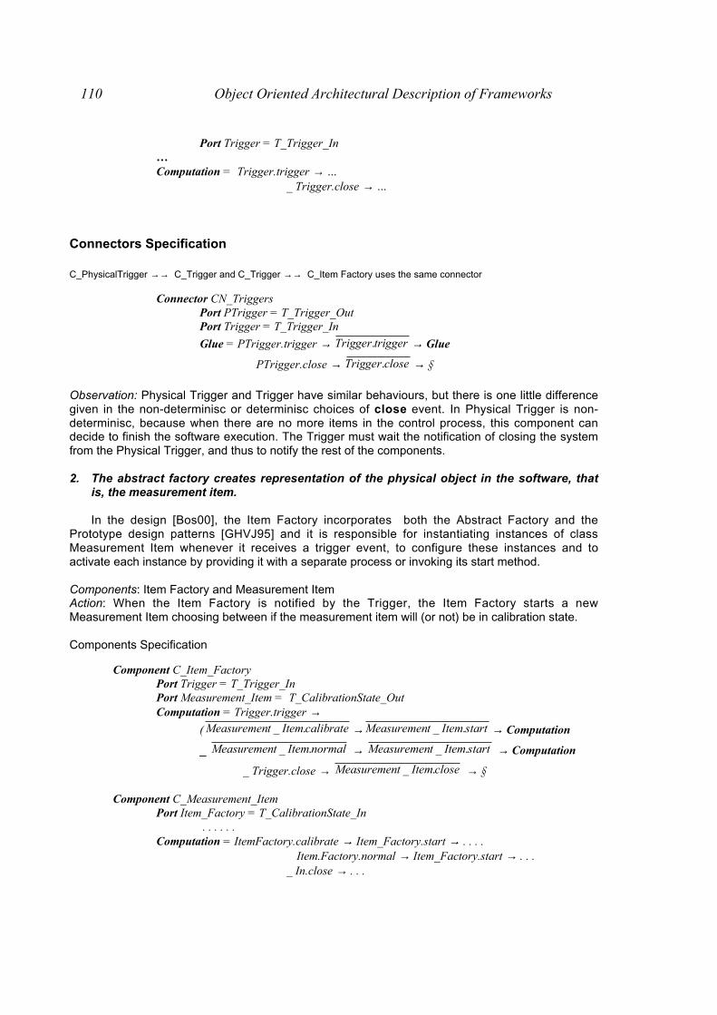
110 Object Oriented Architectural Description of Frameworks
Port Trigger = T_Trigger_In…Computation = Trigger.trigger → …
_ Trigger.close → …
Connectors Specification
C_PhysicalTrigger →→ C_Trigger and C_Trigger →→ C_Item Factory uses the same connector
Connector CN_TriggersPort PTrigger = T_Trigger_OutPort Trigger = T_Trigger_In
Glue = PTrigger.trigger → triggerTrigger. → Glue
PTrigger.close → closeTrigger. → §
Observation: Physical Trigger and Trigger have similar behaviours, but there is one little differencegiven in the non-determinisc or determinisc choices of close event. In Physical Trigger is non-determinisc, because when there are no more items in the control process, this component candecide to finish the software execution. The Trigger must wait the notification of closing the systemfrom the Physical Trigger, and thus to notify the rest of the components.
2. The abstract factory creates representation of the physical object in the software, thatis, the measurement item.
In the design [Bos00], the Item Factory incorporates both the Abstract Factory and thePrototype design patterns [GHVJ95] and it is responsible for instantiating instances of classMeasurement Item whenever it receives a trigger event, to configure these instances and toactivate each instance by providing it with a separate process or invoking its start method.
Components: Item Factory and Measurement ItemAction: When the Item Factory is notified by the Trigger, the Item Factory starts a newMeasurement Item choosing between if the measurement item will (or not) be in calibration state.
Components Specification
Component C_Item_FactoryPort Trigger = T_Trigger_InPort Measurement_Item = T_CalibrationState_Out Computation = Trigger.trigger →
( calibrateItemtMeasuremen ._ → startItemtMeasuremen ._ → Computation
_ normalItemtMeasuremen ._ → startItemtMeasuremen ._ → Computation
_ Trigger.close → closeItemtMeasuremen ._ → §
Component C_Measurement_ItemPort Item_Factory = T_CalibrationState_In
. . . . . .Computation = ItemFactory.calibrate → Item_Factory.start → . . . .
Item.Factory.normal → Item_Factory.start → . . . _ In.close → . . .

References 111
Item Factory →→ Measurement Item
Connector CN_ToMIRole IF = T_Calibration_OutRole MI = T_Calibration_In
Glue = (IF.calibrate → calibrateMI. IF.normal → normalMI. )
→ IF.start → startMI. → Glue
_ IF.close → closeMI. → §
Obervation : In the Computation of C_Item_Factory, there is a non-deterministic choice betweentwo events CALIBRATE and NORMAL and this is because of the class structure of Item Factorycontains an instance of MeasurementItem and a state variable indicating whether the system is incalibration mode or in normal operation [Bos00]. The state is initialized in the Item Factory, thus,we can think that the choice between the two different modes of operation has to be made by itself.
3. The measurement item requests the sensor to measure the physical object
The measurement item is the object that contains the data collected from the sensors concerningthe physical measurement item and the Measurement Value represents one aspect of the physicalmeasurement item that is used by the system [Bos00]. Thus, the measurement item has acollection of measurements values, and these last ones represent the data of the measurementitem.
Components: Measurement Item, Measurement Values and SensorAction: When the measurement item requests the sensor(s) to measure the physical object, in fact,this action is forwarded to the measurement values of the measurement item, and thesecomponents will get the value from the connected sensors. In this stage, the calibration/normalstate is not important, so in both states the calculation phase is made.
Components Specification
Component C_Measurement_ItemPort Item_Factory = T_CalibrationState_InPort MValues = T_Calculation_Out. . . . . .Computation = ItemFactory.calibrate → Item_Factory.start → Calculate → . . .
Item.Factory.normal → Item_Factory.start → Calculate → . . .
_ In.close → closeMValues. → . . .
where Calculate = ncalculatioperformMValues _.
Component C_MeasurementValuePort Measurement_Item = T_Calculation_InPort Sensors = T_Measure_Out
Computation = Measurement_Item.perform_calculation → valuegetSensors _. → . . . . .
_ Measurement_Item.close → closeSensors. → §
Component C_SensorPort Measurement _Item = T_Measure_In
CCoonnnneecc ttoorrss SSppeecc ii ff ii ccaa tt iioonn

112 Object Oriented Architectural Description of Frameworks
. . . . .Computation = Measurement_Item.get_value → . . . . . _ Measurement_Item.close → . . . . .
Connectors Specification
Measurement Item →→ Measurement Values
Connector CN_ ToMV (numMvs: 1..)Role MI = T_Calculation_OutRole MV1..numMvs = T_Calculation_InGlue = MI.perform_calculation
→ numMvsi ..1:∀ _ ncalculatioperformMVi _. → Glue
. . .
_ MI.close → numMvsi ..1:∀ _ closeMVi . → §
Measurement Values →→ Sensors
Connector CN_ToSensor (numSs:1..)Role MV = T_Measure_OutRole Sensors1.. numSs = T_Measure_In
Glue = MV.get_value → numSsi ..1:∀ _ valuegetSensorsi _. → . . .
_ MV.close → numSsi ..1:∀ _ closeSensorsi . → §
4. The sensor sends back the result to the measurement item that stores the results
The Sensor is the software representation of a hardware device that meaures one particularvariable of the item in question. The sensor is responsible for maintaining an accurate model of theahardware sensor. To achieve this, the sensor communicates with the hardware sensor. The waythe sensor updates itself with the data in the physical sensor can vary, depending on the sensortype and the application.
Components: Measurement Values, Sensor and Physical SensorAction: Following from the previous step, the sensor must send the measured value to themeasurement item.
Components Specification
Component C_MeasurementValuePort Measurement_Item = T_Calculation_InPort Sensors = T_Measure_OutComputation = Measurement_Item.perform_calculation
→ valuegetSensors _. → Sensors.receive?val → Computation
. . . . .
_ Measurement_Item.close → closeSensors. → §
Component C_SensorPort Measurement _Item = T_Measure_InPort Physical_Sensor = T_Output_InputComputation = Measurement_Item.get_value →
( valsendItemtMeasuremen !._ → Computation
_ askSensorPhysical ._ → Physical_Sensor.receive?result →

References 113
resultsendItemtMeasuremen !._ → Computation )
_ askSensorPhysical ._ →Physical_Sensor.receive?result → Computation
_ Measurement_Item.close → closeSensorPhysical ._ → §
Component C_Physical_SensorPort Sensor = T_InputOutput
Computation = Sensor.receive → )(!. valmeasuresendSensor → Computation
_ Sensor.close → §
Connectors Specification
Measurement Value →→ Sensor
Connector CN_ToSensor (numSs: 1..n)Role MV = T_Measure_OutRole Sensors1..numSs = T_Measure_In
Glue = MV.get_value → numSsi ..1:∀ _ valuegetSensorsi _. →
numSsi ..1:∀ _ Sensorsi.send?val → process_values → valreceiveMV !. → Glue
MV.close → numSsi ..1:∀ _ closeSensorsi . → §
Physical Sensor →→ Sensor
Connector CN_SensorsRole Sensor = T_Output_InputRole PSensor = T_Input_Output
Glue = Sensor.ask → receivePSensor. → PSensor.send?result
→ resultreceiveSensor !. → Glue
_ Sensor.close → closePSensor. → §
Observation : Firstly, it is supposed that the sensor stores the values sent by the physical sensor.We know that there is no way to store internal state of the components with a Wright description.In the Component C_Sensor, the behaviour is given by different non-determinisc choices. The firstone is given by the event ASK and the second one is when it has to return the measured value ofan item aspect. As we explained before, the sensor updates itself, and this can be made forexample, after a time interval the sensor updates its value asking the physical sensor, or whenthere was a change in the physical item, the physical sensor notifies the changed value to thesensor. Another way of updating is when it is required by the client of the sensor, in this case themeasurement item. Thus, let’s make a small analysis of the given non-determinisc choices. Thefirst one is given by the need of updating the value asking the physical sensor (because of timeinterval). The second one is given when the measurement value ask the measured value. In thiscase, the sensor can send the store value, or ask the physical sensor to update the value and sendit.
5. After collecting the required data, the measurement item compares the measured valueswith the ideal values.

114 Object Oriented Architectural Description of Frameworks
Each measurement value contains a set value representing the correct value, a measured valuerepresenting the value measured at the current physical item, and a compare method describinghow to interpret differences between the measured and set values
Components: Measurement Item, Measurement ValuesAction: Based on the obtained data, in normal state of the system, the measurement item mustdecide if the physical item is acceptable or not in the production process. This is done comparingthe measured values with the ideal ones and is performed by each measurement values becausethey keep the ideal and the measured values. Thus the process of comparison is forwarded toeach measurement value, and if all answer positively, the item is acceptable, if not, the item is notacceptable.
Components Specification
Component C_Measurement_ItemPort Item_Factory = T_CalibrationState_InPort MValues = T_Calculation_Out
. . . . . .Computation = ItemFactory.calibrate → Item_Factory.start → Calculate → . . . .
Item.Factory.normal → Item_Factory.start → Calculate→ Compare → Computation
_ In.close → closeMValues. → . . . . .
where Calculate = ncalculatioperformMValues _.
Compare = compareMValues. →MValues.acceptable _ MValues.non_acceptable → . . . . .
Component C_MeasurementValuePort Measurement_Item = T_Calculation_InPort Sensors = T_Measure_Out
Computation = Measurement_Item.perform_calculation → valuegetSensors _.
→ Sensors.receive?val → Computation. . . ._ Measurement_Item.compare → ( acceptableItemtMeasuremen ._ → Computation
_ acceptablenonItemtMeasuremen _._ → Computation )
_ Measurement_Item.close → closeSensors. → §
Connectors Specification
Measurement Item →→ Measurement Values
Connector CN_ ToMV (numMvs: 1..n)Role MI = T_Calculation_OutRole MV1..numMvs = T_Calculation_InGlue = MI.perform_calculation
→ numMvsi ..1:∀ _ ncalculatioperformMVi _. → Glue
. . . . .

References 115
_ MI.compare → numMvsi ..1:∀ _ compareMVi . →( numMvsi ..1:∀ _ MVi.acceptable → Glue
numMvsi ..1:∃ _ MVi.non_acceptable → Glue )
MI.close → numMvsi ..1:∀ _ closeMVi . → §
Observation: As we said in the previous step, it is also supposed that the measurement valuekeeps the last measured value and we explained that this was not possible. Thus, when themeasurement value receives the event of comparing, the decision of acceptability is described asnon-deterministic because in the actual description we do not have elements to evaluate thiscondition.
6. The measurement item sends a message to the actuator requesting the actuationappropriate for the measured data.
Components: Measurement Item, Measurement Values, Actuators and Physical ActuatorsAction: In the normal state of the system, if the item is qualified as non-acceptablee, the actuatorsmust work. So the measurement item asks the actuators to work. But in calibration state, themeasurement Item asks the calibration to the measurement values themselves. This processconsistsin storing the real measured values as ideal values
Components Specification
Component C_Measurement_ItemPort Item_Factory = T_CalibrationState_InPort MValues = T_Calculation_OutPort Actuators = T_Actuate_OutComputation = ItemFactory.calibrate → Item_Factory.start
→ Calculate → calibrateMValues. → Computation Item.Factory.normal → Item_Factory.start
→ Calculate → Compare → Computation
_ In.close → closeMValues. → closeActuators. → §
where Calculate = ncalculatioperformMValues _.
Compare = compareMValues.
→ MValues.acceptable _ MValues.non_acceptable)
→ actuateActuators.
Component C_MeasurementValuePort Measurement_Item = T_Calculation_InPort Sensors = T_Measure_Out
Computation = Measurement_Item.perform_calculation → valuegetSensors _.
→ Sensorsi.receive?val → Computation Measurement_Item.calibrate → Computation
_ Measurement_Item.compare → ( acceptableItemtMeasuremen ._ → Computation
_ acceptablenonItemtMeasuremen _._ → Computation )
_ Measurement_Item.close → closeSensors. → §
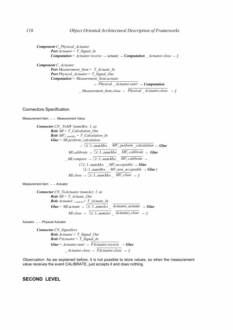
116 Object Oriented Architectural Description of Frameworks
Component C_Physical_ActuatorPort Actuator = T_Signal_InComputation = Actuator.receive → actuate → Computation _ Actuator.close → §
Component C_ActuatorPort Measurement_Item = T_Actuate_InPort Physical_Actuator = T_Signal_OutComputation = Measurement_Item.actuate
→ startActuatorPhysical ._ → Computation
_ Measurement_Item.close → closeActuatorPhysical ._ → §
Connectors Specification
Measurement Item →→ Measurement Value
Connector CN_ ToMV (numMvs: 1..n)Role MI = T_Calculation_OutRole MV1..numMvs = T_Calculation_InGlue = MI.perform_calculation
→ numMvsi ..1:∀ _ ncalculatioperformMVi _. → Glue
MI.calibrate → numMvsi ..1:∀ _ calibrateMVi . → Glue
_ MI.compare → numMvsi ..1:∀ _ calibrateMVi . →( numMvsi ..1:∀ _ MVi.acceptable → Glue
numMvsi ..1:∃ _ MVi.non_acceptable → Glue )
MI.close → numMvsi ..1:∀ _ closeMVi . → §
Measurement Item →→ Actuator
Connector CN_ToActuator (numAct: 1..n)Role MI = T_Actuate_OutRole Actuator 1..numAct= T_Actuate_In
Glue = MI.actuate → numActi ..1:∀ _ actuateActuatori . → Glue
MI.close → numActi ..1:∀ _ closeActuatori . → §
Actuator →→ Physical Actuator
Connector CN_SignallersRole Actuator = T_Signal_OutRole PActuator = T_Signal_In
Glue = Actuator.start → receivePActuator. → Glue
_ Actuator.close → closePActuator. → §
Observation: As we explained before, it is not possible to store values, so when the measurementvalue receives the event CALIBRATE, just accepts it and does nothing.
SECOND LEVEL

References 117
MOTIVATION
As we saw so far, we found different problems in the description. The most remarkablewas the lacking of representation of internal state of the component (observations made in steps 2,4, 5 and 6). In fact, Wright ADL [All97] is focused on the interaction behaviour and there is nopossibility to use the operations given by the components. All their executions are hidden behindthe non-deterministic choices in the specification. Thus, it is no possible to have any specificationabout the functional aspects of the components [San97]
In this level, we decided to solve the previous problem through the use of B AbstractMachines [San97] and refine the architecture using the concept of hierarchy in Wright ADL [All97]in the following details:• The sensor updates itself with the data in the physical sensor and the update can vary ,
depending on the sensor type and the application. Thus, in this framework the updatingbehaviour was abstracted using the Strategy design pattern [GHJV95]• Client Update: The sensor never updates itself , until it is called by a client• Periodic Update: The sensor will update itself with fresh data from the physical
sensor after a given time interval• On-change Update: When the value is changed, the sensor is notified
• The data read from the hardware sensor has to be converted into a value that has somemeaning in the context of the software system. This conversion process can be different,depending on the application an the way the sensor is used. Therefore the conversion hasalso been abstracted as a Calculation Strategy. But the Calculation Strategy is used also byother objects in the framework.
• After the Measurement Item is started, it contains two execution phases: to collect data on thephysical item it represents and to make the actuators actuate appropriately, based on themeasured data and the comparison to the set data. In fact, these two processes areencapsulated in two strategies: Calculation Strategy (described previously) and ActuationStrategy (uses the set of actuator references stored by the measurement item to activate thevarious actuators)
• When the Item Factory is in calibration state, this fact influences the Actuation Strategy of themeasurement item rather than the calculation strategy. Therefore, the normal actuationstrategy is replaced with a calibration strategy that performs the actions required duringcalibration.
ANALYSIS
After an analysis, we detect that the components to be refined are: C_Item Factory,C_Measurement_Item, C_Measurement_Value and C_Sensor. All of them have in common theproblem of not being able to store some special state in their description and, except the first one,have in common that they have associated different strategies.
Here, we present the changes made analyzing each component separately. In this sectionwe will not show the evolution of each change as in the previous section, we will just present thefinal component and the changes made.
Component: ITEM FACTORY
In the step 2 in the previous section, we explained that the item factory decides if thesystem is in calibration or not and we expressed this fact through a non deterministic choicebetween the events CALIBRATE and NORMAL. In fact, the component has a boolean variable toexpress the actual state of the system. Using the concept presented in [San97], we build a newcomponent AM_Item_Factor (which is the representation of the B-Abstract Machine of Factory andexports the operation Is_InCalibration), then we build the connector and we avoid the non-deterministic choice in Item_Factory. As this process only is taken into account in the factoryenvironment, we encapsulated everything using hierarchical description.
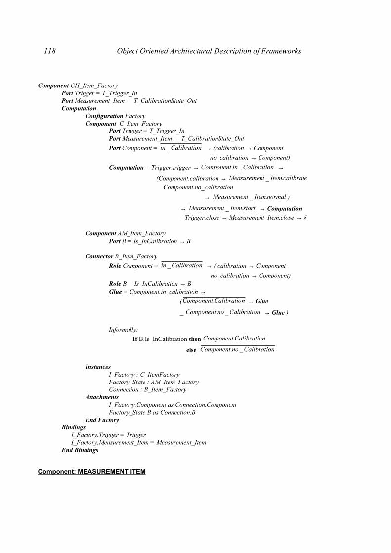
118 Object Oriented Architectural Description of Frameworks
Component CH_Item_FactoryPort Trigger = T_Trigger_InPort Measurement_Item = T_CalibrationState_OutComputation
Configuration FactoryComponent C_Item_Factory
Port Trigger = T_Trigger_InPort Measurement_Item = T_CalibrationState_Out
Port Component = nCalibratioin _ → (calibration → Component
_ no_calibration → Component)
Computation = Trigger.trigger → nCalibratioinComponent _. →
(Component.calibration → calibrateItemtMeasuremen ._ Component.no_calibration
→ normalItemtMeasuremen ._ )
→ startItemtMeasuremen ._ → Computation
_ Trigger.close → Measurement_Item.close → §
Component AM_Item_FactoryPort B = Is_InCalibration → B
Connector B_Item_Factory
Role Component = nCalibratioin _ → ( calibration → Component
no_calibration → Component)Role B = Is_InCalibration → BGlue = Component.in_calibration →
( nCalibratioComponent. → Glue
_ nCalibrationoComponent _. → Glue )
Informally:
If B.Is_InCalibration then nCalibratioComponent.
else nCalibrationoComponent _.
Instances I_Factory : C_ItemFactory Factory_State : AM_Item_Factory Connection : B_Item_FactoryAttachments I_Factory.Component as Connection.Component Factory_State.B as Connection.BEnd Factory
Bindings I_Factory.Trigger = Trigger I_Factory.Measurement_Item = Measurement_ItemEnd Bindings
Component: MEASUREMENT ITEM

References 119
As we said previously, the starting process of the Measurement Item is described in twophases: calculation and actuation phases. If we refer to the start method in the implementation, wewill see:
start
(self calculationStrategy) performCalculation(self actuationStrategy) actuate^self
In fact, the calculation strategy just forwards the calculation process to the measurementitem itself, and this last one forwards the performCalculation operation to its measurement values.In case of actuation strategy, if the system is in normal state, the actuators must work; but if it is incalibration state, just forwards the calibration process to the measurement item itself, and this lastone forwards the calibrate operation to its measurement values.
Thus, we have to add two new new components to represent the Actuation and Calibrationstrategies and their respective connectors. As these concepts are used by other components, wedecide to build mini-styles with the strategies. More details will be given later, we just only add theexpression Style CalculationStrategy, ActuationStrategy As this process only is taken into account in the item environment, we encapsulatedeverything using hierarchical description
Component CH_Measurement_ItemPort Item_Factory = T_CalibrationState_InPort MValues = T_Calculation_OutPort Actuators = T_Actuate_OutComputation
Configuration Item_To_MeasureStyle CalculationStrategy, ActuationStrategyComponent C_Measurement_Item
Port Item_Factory = T_CalibrationState_InPort MValues = T_Calculation_OutPort Actuators = T_Actuate_OutPort ActuationStrategy = T_ActStrategy_OutPort CalculationStrategy = T_CalcStrategy_OutComputation = ItemFactory.calibrate → Item_Factory.start
→ Calculate → Calibrate
→ calibrateMValues. → Computation_ Item.Factory.normal → Item_Factory.start
→ Calculate → Compare → Computation_ In.close → MValues.close → Actuators.close → §
where Calculate = ncalculatioperformnStrategyCalculatio _. →CalculationStrategy.context →
ncalculatioperformMValues _.
Compare = compareMValues. →MValues.acceptable _ MValues.non_acceptable
→ Actuate → actuateActuators.
Actuate = actuatetrategyActuationS .
→ ActuationStrategy.actuators

120 Object Oriented Architectural Description of Frameworks
Calibrate = calibratetrategyActuationS .
→ Actuation.Strategy.calibrate
Instances M_Item : C_Measurement_Item CalcStrategy : C_CalculationStrategy ActStrategy : C_ActuationStrategy CnToCalc : Cn_MIToCalcStrategy CnToAct : Cn_ToActStrategy
Attachments M_Item.CalculationStrategy as CnToCalc.In CalcStrategy.InOut as CnToCalc.Out M_Item.ActuationStrategy as CnToAct.In ActStrategy.InOut as CnToAct.OutEnd Item_To_Measure
BindingsM_Item.Item_Factory = Item_FactoryM_Item.MValues = MValuesM_Item.Actuators = Actuators
End Bindings
Component: MEASUREMENT VALUE
In this component, we have a combination of the problems presented in the two previouslycomponents. Firstly, the component has to decide if the physical item is acceptable or not. In thefirst level, this fact was expressed through a non-deterministic choice, but in fact this situation issimilar to one presented in Item Factory. The measurement values keep information about the lastmeasured value and the ideal value for an aspect of the item, and can determine the condition ofthe acceptability of the item comparing this value. Thus, we apply the technique of [San97], anddevelop a component AM_MeasurementValue which represents the B Abstract Machine, and thiscomponent can export three operations: set_value (which stores the measured value), ideal_value(which calibrates the value) and is-acceptable (which returns True (or False) if the item is (not)acceptable).
Besides this, the measurement value has a calculation strategy. When the measurementitem asks the measured value for a specific aspect, the measurement value just calls thecalculation strategy, and this last one will say who will take the measure, in this case, theassociated sensor.
As this process only is taken into account in the item environment, we encapsulatedeverything using hierarchical description
Component CH_MeasurementValuePort Measurement_Item = T_Calculation_InPort Sensors = T_Measure_OutComputation
Configuration ValueComponent C_MeasurementValue
Style CalculationStrategyPort Measurement_Item = T_Calculation_InPort Sensors = T_Measure_OutPort CalculationStrategy = T_CalcStrategy_In
Port Component = valvalueset !_ → Component
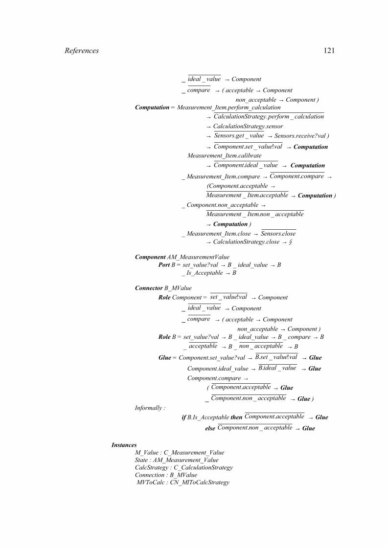
References 121
_ valueideal _ → Component
_ compare → ( acceptable → Component
non_acceptable → Component )Computation = Measurement_Item.perform_calculation
→ ncalculatioperformnStrategyCalculatio _.
→ CalculationStrategy.sensor
→ valuegetSensors _. → Sensors.receive?val )
→ valvaluesetComponent !_. → Computation Measurement_Item.calibrate
→ valueidealComponent _. → Computation
_ Measurement_Item.compare → compareComponent. → (Component.acceptable →
acceptableItemtMeasuremen ._ → Computation )
_ Component.non_acceptable →acceptablenonItemtMeasuremen _._
→ Computation )
_ Measurement_Item.close → closeSensors.→ CalculationStrategy.close → §
Component AM_MeasurementValuePort B = set_value?val → B _ ideal_value → B
_ Is_Acceptable → B
Connector B_MValue
Role Component = valvalueset !_ → Component
_ valueideal _ → Component
_ compare → ( acceptable → Component
non_acceptable → Component )Role B = set_value?val → B _ ideal_value → B _ compare → B
_ acceptable → B _ acceptablenon _ → B
Glue = Component.set_value?val → valvaluesetB !_. → Glue
Component.ideal_value → valueidealB _. → Glue
Component.compare → ( acceptableComponent. → Glue
_ acceptablenonComponent _. → Glue )
Informally :
if B.Is_Acceptable then acceptableComponent. → Glue
else acceptablenonComponent _. → Glue
InstancesM_Value : C_Measurement_ValueState : AM_Measurement_ValueCalcStrategy : C_CalculationStrategyConnection : B_MValue MVToCalc : CN_MIToCalcStrategy

122 Object Oriented Architectural Description of Frameworks
AttachmentsM_Value.CalculationStrategy as MVToCalc.InCalcStrategy.InOut as MVToCalc.OutM_Value.Component as Connection.ComponentState.B as Connection.B
End ValueBindings
M_Value.Measurement_Item = Measurement_ItemM_Value. Sensors = Sensors
End Bindings
Component: SENSOR
This component present the same situation as Measurement Value. It has associated aCalculation Strategy, an Update Strategy and must keep information about internal state. TheCalculation Strategy just forwards the request to the sensor itself and the sensor ask the physicalsensor to measure the item. The Update Strategy decides when the sensor must update its value .The internal state is represented using [San97] and the component AM_Sensor exports twooperations: set_value (which stores the measured value) and measured_value (which returns thevalue).
As this process only is taken into account in the item environment, we encapsulatedeverything using hierarchical description
Component CH_SensorPort Measurement _Item = T_Measure_InPort Physical_Sensor = T_Output_InputComputation
Configuration SensorDeviceStyle CalculationStrategy, UpdateStrategyComponent C_Sensor
Port Measurement _Item = T_Measure_InPort Physical_Sensor = T_Output_InputPort CalculationStrategy = T_CalcStrategy_OutPort UpdateStrategy = T_Update_Out
Port Component = valuemeasured _ → measured_value?val → Component
_ valvalueset !_ → Component
Computation = Measurement_Item.get_value
→ updateclienttegyUpdateStra _.
→ ( UpdateStrategy.context
→ valuemeasuredComponent _. → Component.measured_value?val →
valsendItemtMeasuremen !._ → Computation
UpdateStrategy.calculate_value →ncalculatioperformnStrategyCalculatio _.
→ CalculationStrategy.context
→ askSensorPhysical ._
→ Physical_Sensor.receive?result
→ resultvaluesetComponent !_. →
resultsendItemtMeasuremen !._
→ Computation )
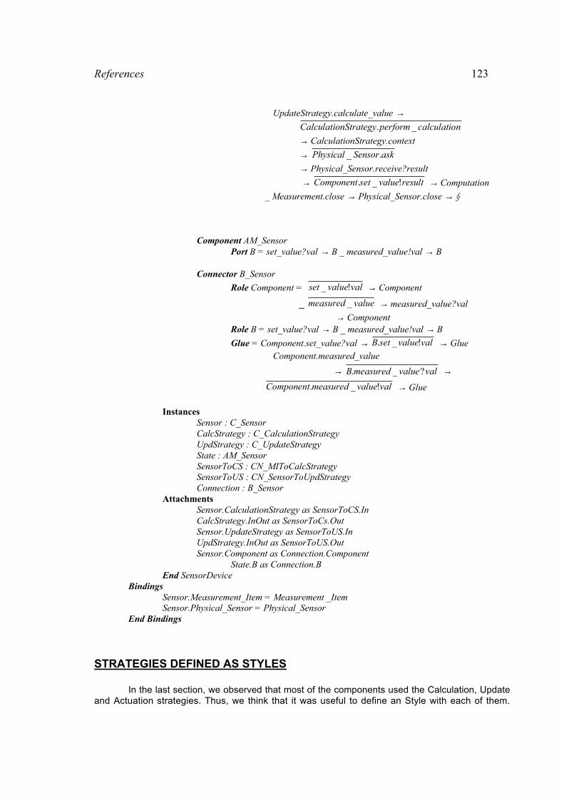
References 123
UpdateStrategy.calculate_value →ncalculatioperformnStrategyCalculatio _.
→ CalculationStrategy.context
→ askSensorPhysical ._
→ Physical_Sensor.receive?result
→ resultvaluesetComponent !_. → Computation
_ Measurement.close → Physical_Sensor.close → §
Component AM_SensorPort B = set_value?val → B _ measured_value!val → B
Connector B_Sensor
Role Component = valvalueset !_ → Component
_ valuemeasured _ → measured_value?val
→ ComponentRole B = set_value?val → B _ measured_value!val → B
Glue = Component.set_value?val → valvaluesetB !_. → Glue Component.measured_value
→ valvaluemeasuredB ?_. →valvaluemeasuredComponent !_. → Glue
InstancesSensor : C_SensorCalcStrategy : C_CalculationStrategyUpdStrategy : C_UpdateStrategyState : AM_SensorSensorToCS : CN_MIToCalcStrategySensorToUS : CN_SensorToUpdStrategyConnection : B_Sensor
AttachmentsSensor.CalculationStrategy as SensorToCS.InCalcStrategy.InOut as SensorToCs.OutSensor.UpdateStrategy as SensorToUS.InUpdStrategy.InOut as SensorToUS.OutSensor.Component as Connection.Component
State.B as Connection.BEnd SensorDevice
BindingsSensor.Measurement_Item = Measurement _Item Sensor.Physical_Sensor = Physical_Sensor
End Bindings
STRATEGIES DEFINED AS STYLES
In the last section, we observed that most of the components used the Calculation, Updateand Actuation strategies. Thus, we think that it was useful to define an Style with each of them.
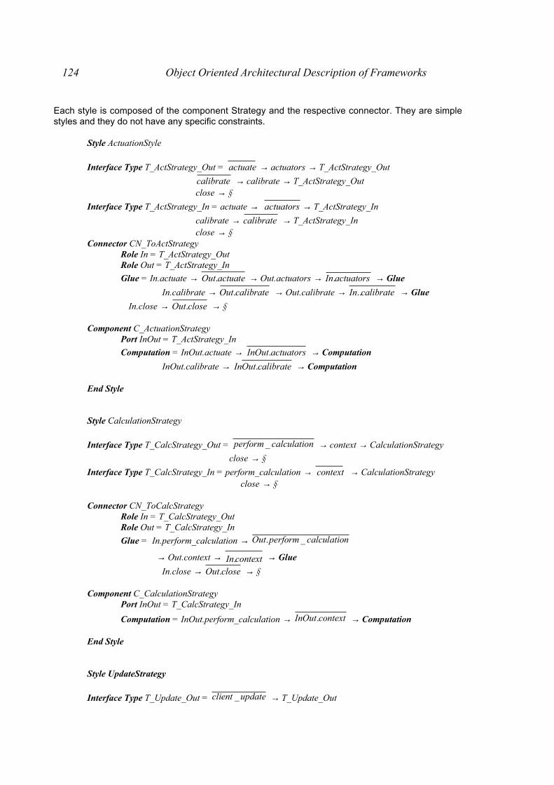
124 Object Oriented Architectural Description of Frameworks
Each style is composed of the component Strategy and the respective connector. They are simplestyles and they do not have any specific constraints.
Style ActuationStyle
Interface Type T_ActStrategy_Out = actuate → actuators → T_ActStrategy_Out
calibrate → calibrate → T_ActStrategy_Out close → §
Interface Type T_ActStrategy_In = actuate → actuators → T_ActStrategy_In
calibrate → calibrate → T_ActStrategy_In close → §
Connector CN_ToActStrategyRole In = T_ActStrategy_OutRole Out = T_ActStrategy_In
Glue = In.actuate → actuateOut. → Out.actuators → actuatorsIn. → Glue
In.calibrate → calibrateOut. → Out.calibrate → calibrateIn.. → Glue
In.close → closeOut. → §
Component C_ActuationStrategyPort InOut = T_ActStrategy_In
Computation = InOut.actuate → actuatorsInOut. → Computation
InOut.calibrate → calibrateOutIn . → Computation
End Style
Style CalculationStrategy
Interface Type T_CalcStrategy_Out = ncalculatioperform _ → context → CalculationStrategy
close → §
Interface Type T_CalcStrategy_In = perform_calculation → context → CalculationStrategy close → §
Connector CN_ToCalcStrategyRole In = T_CalcStrategy_OutRole Out = T_CalcStrategy_In
Glue = In.perform_calculation → ncalculatioperformOut _.
→ Out.context → contextIn. → Glue
In.close → closeOut. → §
Component C_CalculationStrategyPort InOut = T_CalcStrategy_In
Computation = InOut.perform_calculation → contextInOut. → Computation
End Style
Style UpdateStrategy
Interface Type T_Update_Out = updateclient _ → T_Update_Out

References 125
_ calculate_value → T_Update_Out_ context → T_Update_Out
Interface Type T_Update_In = client_update → T_Update_In
_ Valuecalculate _ → T_Update_In
_ context → T_Update_In
Connector CN_ToUpdateStrategyRole In = T_Update_OutRole Out = T_Update_In
Glue = In.client_update → updateclientOut _. → Glue
_ Out.calculate_value → valuecalculateIn _. → Glue
_ Out.context → contextIn. → Glue
Component C_UpdateStrategyPort InOut = client_update → InOut
_ valuecalculate _ → InOut
_ context → InOut
Computation = InOut.client_update → ( valuecalculateInOut _. → Computation
_ contextInOut. → Computation )
_ valuecalculateInOut _. → Computation
End Style
Interface Types
Interface Type T_Signal_Out = start → T_Signal_Sender _ close → §Interface Type T_Signal_In = receive → T_Signal_Receiver _ close → §
Interface Type T_Trigger_Out = trigger → T_Trigger_Out _ close → §
Interface Type T_Trigger_ In = trigger → T_Trigger_In close → §
Interface Type T_Output_Input = ask → receive?item → T_Output_Input _ close → §
Interface Type T_Input_Output = receive → resultsend! → T_Input_Output _ close → §
Interface Type T_Calibration_Out = calibrate → start → T_Calibration_Out
_ normal → start → T_Calibration_Out _ close → §Interface Type T_Calibration_In = calibrate → start → T_T_Calibration_In
normal → start → T_Calibration close → §
Interface Type T_Calculation_Out = ncalculatioperform _ → T_Calculation_ Out
_ calibrate → T_Calculation _Out
_ compare → (acceptable → T_Calculation _Out
_ non_acceptable → T_Calculation _Out )
_ close → §Interface Type T_Calculation_In = perform_calculation → T_Calculation_In
calibrate → T_Calculation_In
compare → ( acceptable → T_Calculation_Out
_ acceptablenon _ → T_Calculation_Out)
_ close → §

126 Object Oriented Architectural Description of Frameworks
Interface Type T_Actuate_Out = actuate → T_Actuate_Out _ close → §Interface Type T_Actuate_In = actuate → T_Actuate_In close → §
Interface Type T_Measure_Out = valueget _ → receive?val → T_Measure_Out _ close → §
Interface Type T_Measure_In = get_value → valsend! → T_Measure_In close → §
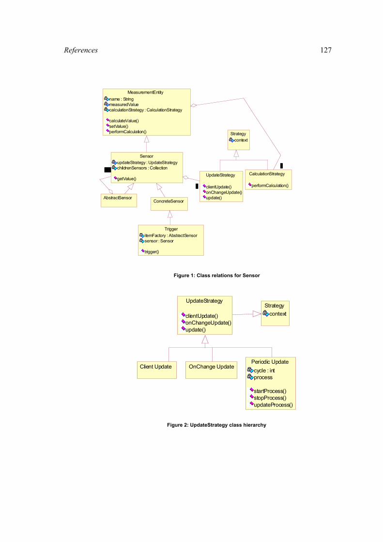
References 127
ConcreteSensor
Strategy
context
AbstractSensor
Sensor
updateStrategy : UpdateStrategychildrenSensors : Collection
getValue()
1..*1..*UpdateStrategy
clientUpdate()onChangeUpdate()update()
11
Trigger
itemFactory : AbstractSensorsensor : Sensor
trigger()
MeasurementEntity
name : StringmeasuredValuecalculationStrategy : CalculationStrategy
calculateValue()setValue()performCalculation()
CalculationStrategy
performCalculation()
11
Figure 1: Class relations for Sensor
Strategy
context
UpdateStrategy
clientUpdate()onChangeUpdate()update()
Client Update OnChange UpdatePeriodic Update
cycle : intprocess
startProcess()stopProcess()updateProcess()
Figure 2: UpdateStrategy class hierarchy
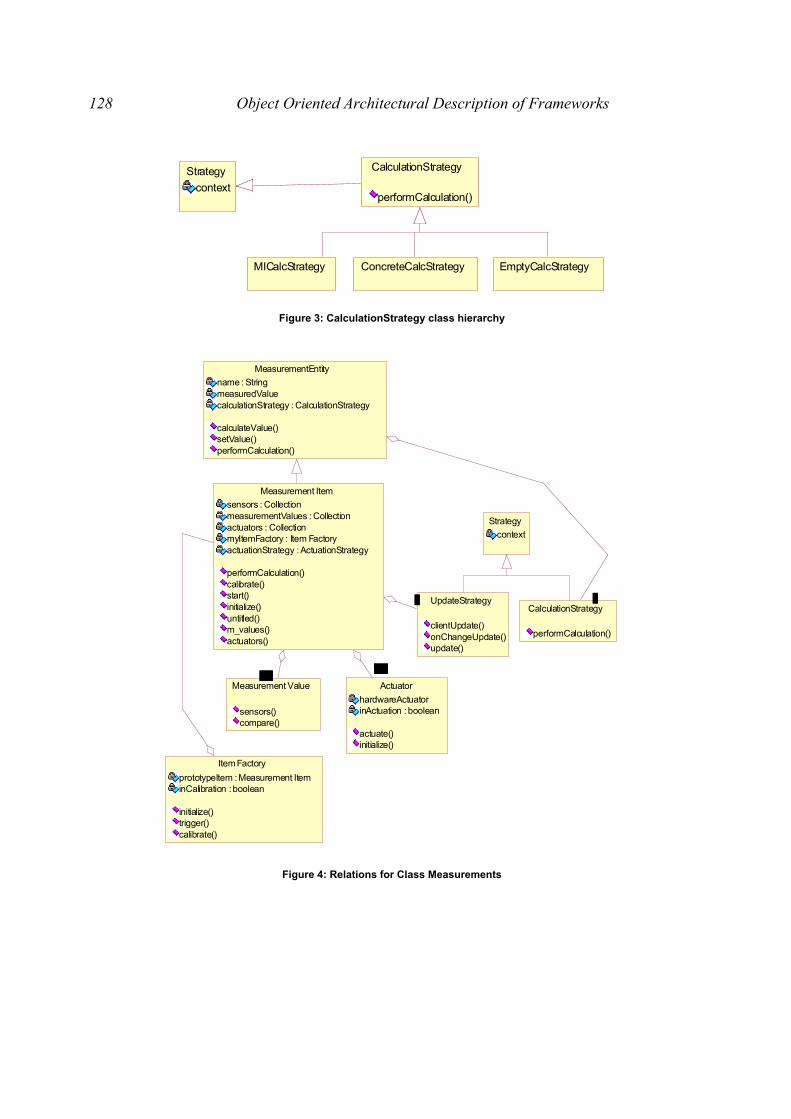
128 Object Oriented Architectural Description of Frameworks
Strategy
context
CalculationStrategy
performCalculation()
MICalcStrategy ConcreteCalcStrategy EmptyCalcStrategy
Figure 3: CalculationStrategy class hierarchy
Strategy
context
Measurement Value
sensors()compare()
Actuator
hardwareActuatorinActuation : boolean
actuate()initialize()
Item Factory
prototypeItem : Measurement IteminCalibration : boolean
initialize()trigger()calibrate()
Measurement Item
sensors : CollectionmeasurementValues : Collectionactuators : CollectionmyItemFactory : Item FactoryactuationStrategy : ActuationStrategy
performCalculation()calibrate()start()initialize()untitled()m_values()actuators()
1..*1..*1..*1..*
UpdateStrategy
clientUpdate()onChangeUpdate()update()
11
MeasurementEntity
name : StringmeasuredValuecalculationStrategy : CalculationStrategy
calculateValue()setValue()performCalculation()
CalculationStrategy
performCalculation()
11
Figure 4: Relations for Class Measurements

References 129
Sensor
updateStrategy : UpdateStrategychildrenSensors : Collection
getValue()
Atomic MVComposed MV
Measurement Value
sensors()compare()
Strategy
context
MeasurementEntity
name : StringmeasuredValuecalculationStrategy : CalculationStrategy
calculateValue()setValue()performCalculation()
CalculationStrategy
performCalculation()11
Figure 5: MeasurementValue class relations
Strategy
context
UpdateStrategy
clientUpdate()onChangeUpdate()update()
Measurement Item
sensors : CollectionmeasurementValues : Collectionactuators : CollectionmyItemFactory : Item FactoryactuationStrategy : ActuationStrategy
performCalculation()calibrate()start()initialize()untitled()m_values()actuators()
CalibrationStrategy
ActuationStrategy
actuate()
Item Factory
prototypeItem : Measurement IteminCalibration : boolean
initialize()trigger()calibrate()
Figure 6: ItemFactory Class

130 Object Oriented Architectural Description of Frameworks
Strategy
context
Measurement Item
sensors : CollectionmeasurementValues : Collectionactuators : CollectionmyItemFactory : Item FactoryactuationStrategy : ActuationStrategy
performCalculation()calibrate()start()initialize()untitled()m_values()actuators()
Actuator
hardwareActuatorinActuation : boolean
actuate()initialize()
ActuationStrategy
actuate()
11
Figure 7: Context of class Actuator
INTERACTION DIAGRAMS
: Trigger : Item Factory : Measurement Item
: EmptyCalcStrategy
: Measurement Value
: EmptyCalcStrategy
: Sensor : Client Update : Physical
Sensor : Physical
Triggertrigger( )
trigger( )start( )
performCalculation( )
m_values( )
performCalculation( )performCalculation( )
sensors( )
performCalculation( )
setValue( )
update( )
getValue( )
measure( )
setValue( )
Figure 8: Normal Process with the Sensor data updated through the request of the System
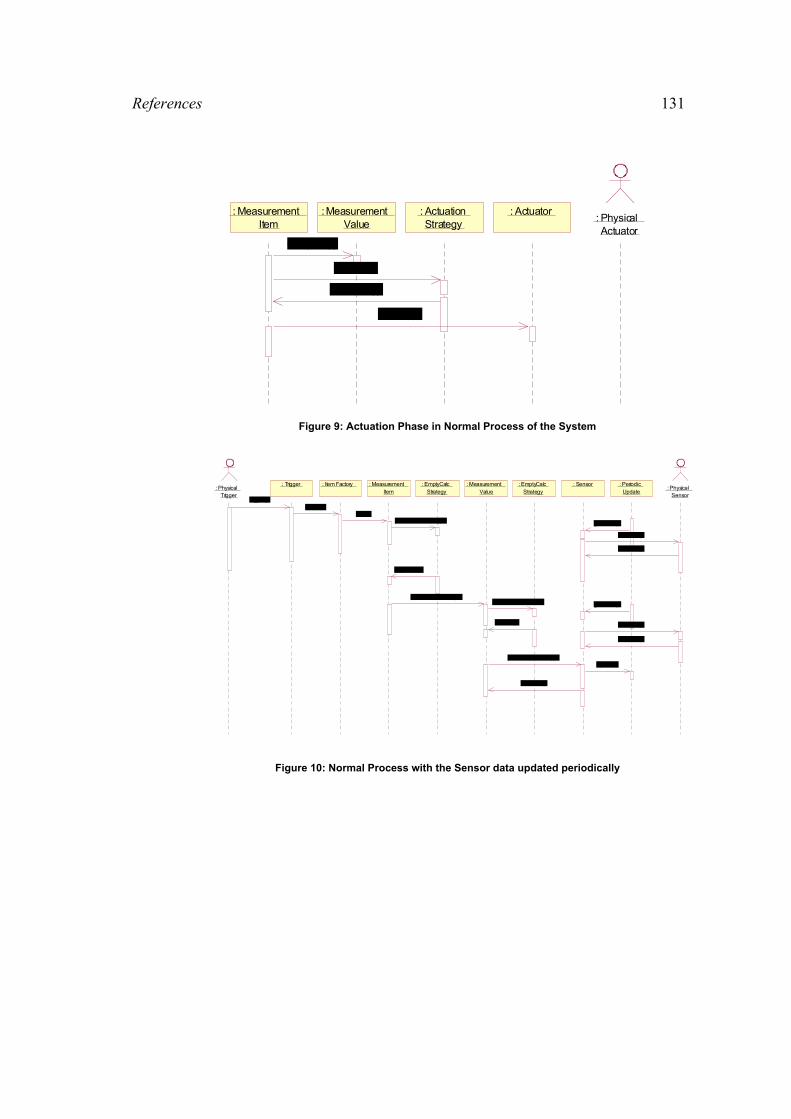
References 131
: Measurement Item
: Measurement Value
: ActuationStrategy
: Actuator : Physical
Actuatorcompare( )
actuate( )
actuators( )
actuate( )
Figure 9: Actuation Phase in Normal Process of the System
: Trigger : Item Factory : Measurement Item
: EmptyCalcStrategy
: Measurement Value
: EmptyCalcStrategy
: Sensor : Periodic Update
: Physical Sensor
: Physical Trigger
trigger( )trigger( )
start( )performCalculation( )
m_values( )
performCalculation( )performCalculation( )
sensors( )
performCalculation( )
getValue( )
getValue( )
measure( )
measure( )
setValue( )
setValue( )
setValue( )
update( )
Figure 10: Normal Process with the Sensor data updated periodically
Appendix B
This appendix shows a complete analysis of the application of Wright ADL to describe a component of aframework. The objective is to see an step-by-step process of how to get an architectural description using
this ADL.
A GENERIC COORDINATION ABSTRACTION FOR MANAGING SHARED RESOURCES
In [CTN97], a Coordination Component Framework for Open Distributed Systems wasdeveloped. They introduce different solutions to coordination problems, and each solution isembodied in a component in the framework. One of these components is used to provide solutionto the management of shared resource.
In[CDK94], they define that there are some common elements which define the structure ofthese solutions : the definition of the resource, and the definition of the allocation policy. Somefeatures of these elements are fundamental for the specification of the solutions. For the resourcethey are basically : the size of the resource, and the number of concurrent entities which canaccess the resource at the same time. For the allocation policy they are basically : the order inwhich the resource is going to be assigned, the maximum allowed to each entity, if there will bepriorities on the requests of the allocations, and what to do with the allocation requests that cannotbe processed simultaneously (to define a waiting queue of entities, to ignore them, etc.). There arealso some fault-tolerance aspects like what to do in case of software failures (to ignore precedentrequest, to guarantee recovery, etc.) that have taken into account. All these aspects define theparameters of variability of the generic coordination abstraction that could be specified and thatcan be used to generate specific coordination solutions]
One example shown to see how the component is applied is a toy banking system. In thiscase the resource is an account database which is shared by multiple teller machines. The tellermachines need to get information from the account database in order to check a client’s account.They also need to update account information if they have given money to a client. To keep thedatabase consistent we need an access policy to regulate the multiple requests.
As a solution for this regulation they introduce an access policy component. This solutionnot only provides access regulation, but also explicitness of architecture and flexibility.
8.4 REQUIREMENTS
The main goal of the design is to implement the access policy to the database in areusable and configurable way. In terms of the component oriented approach, this means that wewant to have a structure where we can plug in different policies, without having to change otherparts of the solution. Three kinds of policies are distinguished:
Policies that need no other information about the requests: This is the easiest kind ofpolicy. They can do their job without any knowledge about the commands they have to dispatch. Atypical example is a FIFO policy: no matter what commands come in, the policy just dispatchesthem in order they come in.
Policies that need type information about the requests: This kind of policy depends on the“nature” of the command: every commandtype has one or more properties which are needed bythe policy. A typical example for this case is the readers/writers policy. The policy has to know if acommand is a reader or a writer command. So this information must be made available in oursolution.
Policies that need external information about the requests: This kind of policy depends oninformation which can be different for each instance of a command. It can be thought as a prioritypolicy, where, depending on the sender of the request, a command has a certain priority. Again,somehow this information must be available to the policy.
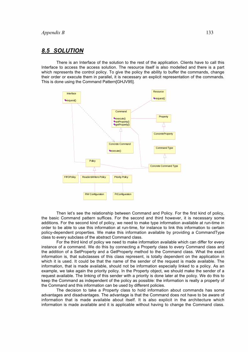
Appendix B 133
8.5 SOLUTION
There is an Interface of the solution to the rest of the application. Clients have to call thisInterface to access the access solution. The resource itself is also modelled and there is a partwhich represents the control policy. To give the policy the ability to buffer the commands, changetheir order or execute them in parallel, it is necessary an explicit representation of the commands.This is done using the Command Pattern[GHJV95].
Concrete Command
execute()
ConcreteProperty
Property
Resource
request()
Command Type
FIFOPolicy ReadersWriters Policy
RW Configuration
Priority Policy
PrConfiguration
Interface
request()
Command
execute()setProperty()getProperty()
Policy
Concrete Command Type
Then let’s see the relationship between Command and Policy. For the first kind of policy,the basic Command pattern suffices. For the second and third however, it is necessary someadditions. For the second kind of policy, we need to make type information available at run-time inorder to be able to use this information at run-time, for instance to link this information to certainpolicy-dependent properties. We make this information available by providing a CommandTypeclass to every subclass of the abstract Command class.
For the third kind of policy we need to make information available which can differ for everyinstance of a command. We do this by connecting a Property class to every Command class andthe addition of a SetProperty and a GetProperty method to the Command class. What the exactinformation is, that subclasses of this class represent, is totally dependent on the application inwhich it is used. It could be that the name of the sender of the request is made available. Theinformation, that is made available, should not be information especially linked to a policy. As anexample, we take again the priority policy. In the Property object, we should make the sender of arequest available. The linking of this sender with a priority is done later at the policy. We do this tokeep the Command as independent of the policy as possible: the information is really a property ofthe Command and this information can be used by different policies.
The decision to take a Property class to hold information about commands has someadvantages and disadvantages. The advantage is that the Command does not have to be aware ofinformation that is made available about itself. It is also explicit in the architecture whichinformation is made available and it is applicable without having to change the Command class.
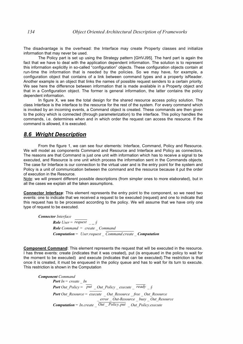
134 Object Oriented Architectural Description of Frameworks
The disadvantage is the overhead: the Interface may create Property classes and initializeinformation that may never be used.
The Policy part is set up using the Strategy pattern [GHVJ95]. The hard part is again thefact that we have to deal with the application dependent information. The solution is to representthis information explicitly in so-called “configuration” objects. These configuration objects contain atrun-time the information that is needed by the policies. So we may have, for example, aconfiguration object that contains of a link between command types and a property isReader.Another example is an object that links the names of possible request senders to a certain priority.We see here the difference between information that is made available in a Property object andthat in a Configuration object. The former is general information, the latter contains the policydependent information.
In figure X, we see the total design for the shared resource access policy solution. Theclass Interface is the interface to the resource for the rest of the system. For every command whichis invoked by an incoming events, a Command object is created. These commands are then givento the policy which is connected (through parameterization) to the interface. This policy handles thecommands, i.e. determines when and in which order the request can access the resource. If thecommand is allowed, it is executed.
8.6 Wright Description
From the figure 1, we can see four elements: Interface, Command, Policy and Resource.We will model as components Command and Resource and Interface and Policy as connectors.The reasons are that Command is just one unit with information which has to receive a signal to beexecuted, and Resource is one unit which process the information sent in the Commands objects.The case for Interface is our connection to the virtual user and is the entry point for the system andPolicy is a unit of communication between the command and the resource because it put the orderof execution in the Resource.Note: we will present different possible descriptions (from simpler ones to more elaborated), but inall the cases we explain all the taken assumptions.
Connector Interface: This element represents the entry point to the component, so we need twoevents: one to indicate that we received a request to be executed (request) and one to indicate thatthis request has to be processed according to the policy. We will assume that we have only onetype of request to be executed.
Connector Interface
Role User = request _ _ §
Role Command = create _ Command
Computation = User.request _ createCommand . _ Computation
Component Command: This element represents the request that will be executed in the resource.I has three events: create (indicates that it was created), put (is enqueued in the policy to wait forthe moment to be executed) and execute (indicates that can be executed).The restriction is thatonce it is created, it must be enqueued in the policy queue and has to wait for its turn to execute.This restriction is shown in the Computation
Component CommandPort In = create _ In
Port Out_Policy = put _ Out_Policy _ execute _ ready _ §
Port Out_Resource = execute _ Out_Resource _ free _ Out_Resource_ error _ Out-Resource _ busy _ Out_Resource
Computation = In.create _ putPolicyOut ._ _ Out_Policy.execute

Appendix B 135
_ Continue _ readyPolicyOut ._ _ §
where Continue = Out_Resource.free _ executesourceOut .Re_ _ §
_ executesourceOut .Re_ _ Out_Resource.error _ Continue
_ executesourceOut .Re_ _ Out_Resource.busy _ Continue
Component Resource: This element is any context can answer to three states associated toevents : free(can accept any request), request(receives the request), busy(processing state of therequest). The only condition to be fullfilled is that:
" while the resource is available sends the event free" but when it receives the request, has to notify that the state is busy and that can
not execute the request event.Both cases are shown in the computation of the component.
Component Resource
Port In = execute _ In _ free _ In _ busy _ In _ §
Computation = freeIn. _ In.execute _ Continue _ Computation
where Continue = In.execute _ busyIn. _ Continue _ §
Connector Policy: This element represents the algoritm that will administrate the order ofexecution of the commands. Now, we will consider that the policy is FIFO and that there are noconstraints in the amount of commands that the policy queue can manage.
Connector Policy
Role Command = put _ Command _ execute _ ready _ §
Computation = Command.put _ executeCommand._ Command.ready _ Computation _ §
Trick: We need a superfluous connector between Command and Resource components.
Connector Superfluous
Role Command = execute _ Command _ free _ Command _ error _ Command _ busy _ Command
Role Resource = execute _ Resource _ free _ Resource _ busy _ Resource _ §
Glue = Command.execute _ executesource.Re _ Glue
_ freesource.Re _ Command.free _ Glue
_ busysource.Re _ Command.busy _ Glue
_ §
With these four architectural elements, we get a michroarchitecture to represent themanagement of a shared resource with a FIFO policy and only one type of operation that can beexecuted atomically in the resource. In fact, the architectural description to define thesecomponents is very simple. It is interesting to add/change functionalities to extend theexpressiveness of the different elements.
Some possible variants are:• To have a set of operations to be executed over the resource, e.g. read and write

136 Object Oriented Architectural Description of Frameworks
• To change the policy: Some policies need type information about the requests orneed external information about the requests. We can consider also the possibility ofhaving a waiting queue of requests.
• To check the number of concurrent entities which can access the resource at thesame time.
There are other possible variants that can be taken into account, but our objective is justonly to show how all of them can be applied in our description to get different functionalities.
8.6.1 First Variant: To have a set of operations, e.g. read and write
The fact that we have two operations with conflicts between them (an operation of writingcan not be made during reading process, and reading process can not be taken into account whena writing process is happening) changes the definition of some protocols of Resource, Interfaceand Policy. In all the cases, we must identify what kind of operations is to know how to proceed.
Connector Interface
Role User = read _ User _ write _ User _ § Role CommandReader = create _ CommandReader
Role CommandWriter = create _ CommandWriter
Computation = User.read _ createaderCommand .Re _ Computation
User.write _ createterCommandWri . _ Computation
Connector Policy (nbr: 1.., nbw: 1..)
Role CommandReader1..nbr = put _ CommandReader _ execute _ CommandReader
_ ready _ CommandReader _ §
Role CommandWriter1..nbw = put _ CommandWriter _ execute _ CommandWriter
_ ready _ CommandWriter _ §
Computation = ( ∃ i..k < nbr || CommandReader.put _ executeaderCommand .Re ) _ ∀ i..k CommandReader.ready _ Computation
_ CommandWriter.put _ executeterCommandWri . _ CommandWriter.ready _ Computation
§
The Component Resource must not pay attention to inform that the operation has finished,because in this case it can accept a set of operations of the same type (e.g. readers at the sametime, or just only one writer).
Component Resource (nbr: 1.., nbw: 1..)Port In = execute _ In _ §Computation = E i:1..k || In.execute _ Computation
8.6.2 Second Variant: Generalize the set of commands.
Some requests in a real domain can be categorized as readers or writers of the resource,without be called explicitly read or write. The solution made in [CTN97] is to have an object calledConfiguration which associates the information about the command with its properties (in this case,the property is indicated as isReader or isWriter).
Component Configuration
Port In = property?i _ ( aderisRe _ In _ isWriter _ In)

Appendix B 137
Computation = In.property?i _
( aderisIn Re. _ Computation _ isWriterIn. _ Computation)
The connector Policy is responsible for managing how the commands will be controlled toaccess the shared resource.
Connector Policy (nbc: 1..)
Role Command1..nbc = put _ Command _ execute _ Command
_ ready _ CommandReader _ §
Role Configuration = property?i _
( aderisRe _ Computation _ isWriter _ Computation)
Computation = Commandi.put _ ipropertyionConfigurat !.
_ ( Configuration.isWriter _ executeCommandi.
_ Commandi.ready _ Computation_ Configuration.isReader _ Read _ Computation )
Where Read = (( executeCommandi. || ( ∃ 2..k < nbc || Commandi. put
_ executeCommandi. ) _ ∀ i..k Commandi.ready
8.6.3 Third Variant: Use of commands with properties
This variant is very similar one to second variant. Some commands can occur concurrentlyin the resource and others ones should be executed alone. It is obvious that the architecturalelements to be modified are Configuration and Policy.
Component Configuration
Port In = property?i _ ( _ xopertyhas !Pr _ In)
Computation = In.property?i _ xopertyhasIn !Pr.
Connector Policy (nbc: 1..)
Role Commandi:1..nbc = put _ Command _ execute _ Command
_ ready _ CommandReader _ §
Role Configuration = property?i _ ( _ xopertyhas !Pr _ Configuration )
Computation = Commandi.put _ xpropertyionConfigurat !. _
∃ j :1..k jpropertyionConfigurat !. _ executeCommand j.
_ Commandj.ready _ Computation
∃ j :1..n jpropertyionConfigurat !. _ Read _ Computation
where Read = (( executeCommand j. || (∃ n:2..k < nbc || Commandn. put
_ executeCommandn. ) _ V i..k Commandn.ready
The index i indicate all the commands that have to be executed alone and index j indicateall the commands that can be executed concurrently.
Let’s see in a progressive way what kinds of change we have made thinking in terms ofclasses diagrams:
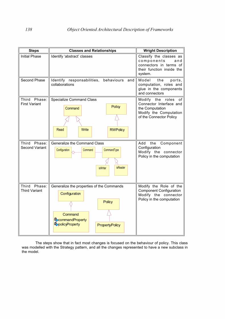
138 Object Oriented Architectural Description of Frameworks
Steps Classes and Relationships Wright Description
Initial Phase Identify ‘abstract’ classes Classify the classes asc o m p o n e n t s a n dconnectors in terms oftheir function inside thesystem.
Second Phase Identify responsabilities, behaviours andcollaborations
Mode l t he po r t s ,computation, roles andglue in the componentsand connectors
Third Phase:First Variant
Specialize Command Class
Command
Read Write
Policy
RWPolicy
Modify the roles ofConnector Interface andthe ComputationModify the Computationof the Connector Policy
Third Phase:Second Variant
Generalize the Command Class
CommandTypeCommandConfiguration
isWriter isReader
Add the ComponentConfigurationModify the connectorPolicy in the computation
Third Phase:Third Variant
Generalize the properties of the Commands
Command
commandPropertypolicyProperty
Configuration
Policy
PropertyPolicy
Modify the Role of theComponent ConfigurationModify the connectorPolicy in the computation
The steps show that in fact most changes is focused on the behaviour of policy. This classwas modelled with the Strategy pattern, and all the changes represented to have a new subclass inthe model.