-7% .. b’ - ntrs.nasa.gov · and mars regardless of whether the capsule conforms to case a or b,...
TRANSCRIPT

-7% - ..
b’
Voyager 0pe.at ions Space Vehicles Division
One Space Park, Redondo Beach. Cal i fornia
https://ntrs.nasa.gov/search.jsp?R=19680009682 2019-08-19T14:37:30+00:00Z

. . .
In- f l ight Configuration
I Opposite View In-f l ight Configuration
h
1
a#
L I \
MODEL OF
TRW RECOMMENDED
S PAC E C RAFT
Stowed Configuration wi th Section of Shroud and Planetarv Vehicle AdaDter
Propulsion Module, Top View Propulsion Module, Bottom View Equipment Module, Bottom View

C O P Y Y
SPACECRAFT Phase B, Task D FINAL REPORT
Volume 1. Summary
OCTOBER 1967
Prepared for
GEORGE C. MARSHALL SPACE FLIGHT CENTER Huntsville, Alabama
SYSTEMS GROUP
Voyager Operations Space Vehicles Division
One Space Park. Redondo Beach, California

P R E F AC E
The resu l t s of TRW's studies of the Voyager spacecraft system as related
to the MSFC Task D requirements a r e presented in this report , in s u m -
m a r y and in detail. Here in Volume 1, the m a j o r conclusions a r e s u m -
mar ized with no attempt to establish the framework of assumptions and
definitions within which they fit. In the remaining 10 volumes, however,
these conclusions a r e reached in the context of all of the significant data
on which they a r e based. To aid in relating the objectives and provisions
of the report requirements as established by MSFC, the following table
locates the response by TRW to the requirements of the contract:
Contract Reference TRW Report Volume
Article I. Scope
Item A 1-7
Item B, Paragraph 1 Paragraph 2 Paragraph 3 Paragraph 4 Paragraph 5
Exhibit A, Contract Guidelines
Section 11, Item A Item B Item C Item D Item E Item F Item G
Section IV, Item A Item B Item C Item D Item E Item F Item G
9 10 10 10 11
296 2 -4
6 6 7
9 - 1 1 5
2 2 2
2 - 4 7 8
7 9 8
Appendix A, Report and Visual Aids Requirements
Section A, Paragraph 1 Paragraph 2
1 2 - 1 1
ii

CONTENTS
Page
I. INTRODUCTION . . . . . . . . . . . . . . . . . . . . . . I
2. SPACECRAFT SYSTEM . . . . . . . . . . . . . . . . . . 3
2.1 General Configuration and Performance . . . . . . 3 2.2 Spacecraft Design. . . . . . . . . . . . . . . . . . 11
2.4 Ground Equipment . . . . . . . . . . . . . . . . . 26 2.5 Design and Operational Alternatives . . . . . . . . 31 2.6 Adaptability and Growth Potential . . . . . . . . . 33
2.3 Science . . . . . . . . . . . . . . . . . . . . . . . 24
3. IMPLEMENTATION. . . . . . . . . . . . . . . . . . . . 36
4. ENGINEERING STUDIES . . . . . . . . . . . . . . . . . 42
4.1 E T 0 Decontamination . . . . . . . . . . . . . . . . 42 4.2 Shroud Separation . . . . . . . . . . . . . . . . . . 43 4.3 Temperature Control 45 4.4 Plume Heating . . . . . . . . . . . . . . . . . . . 46 4.5 Photo-Imaging System . . . . . . . . . . . . . . . 47
. . . . . . . . . . . . . . . .
CONCLUSIONS AND RECOMMENDATIONS . . . . . . . . . . 49
iii

iV

1. INTRODUCTION
In this report , TRW defines in depth a spacecraft configuration
that can be used efficiently for the Martian launch opportunities f rom
1973 through 1979, without hardware modification, carrying either a
5000- o r a 7000-pound capsule.
for different launch opportunities and different capsule weights is the
amount of propellant car r ied .
The only difference in the spacecraft
In reaching i ts recommended configuration and evaluating the pe r -
formance of that configuration, T R W has applied both Case A and Case B
as defined by MSFC; Case A calls f o r a 5000-pound capsule for a l l four
mission years , 1973-79, while Case B calls for a 6000-pound capsule in
1973 and a 7000-pound capsule in 1975, 1977, and 1979. F o r each oppor-
tunity, severa l combinations of requirements a r e identified including
such mission factors as the length of the allotted launch periods, ellip-
ticity of the Martian orbit, and rotation of the orbit af ter injection.
recommended spacecraft can accommodate all of these missions with a
substantial performance margin, except that in 1975 and 1977 the l a rge r
capsule weights will require the more elliptical orbits unless the longer
interplanetary t ra jector ies are flown (Type I1 instead of Type I).
Type I1 t ra jector ies in 1975 and 1977, a very large performance margin
The
With
is available.
include :
0
0
0
0
0
0
The possibilities fo r using excess performance capability
Obtaining orbits smaller in s ize than nominal
Achieving substantial rotations of the orbit apsidal line
Carrying a heavier capsule than nominal
Increasing spac ecraft subsystem weights for improving sys tem performance
Increasing the length of the launch period
Decreasing transit t ime between the ear th and Mars
Regardless of whether the capsule conforms to Case A o r B, the prefer -
able spacecraft design appears to be that which satisfies nominal mission

requirements while affording the greatest flexibility and selectivity in
the exploitation of the capability of the Saturn V for Voyager.
ommended spacecraft design has been optimized to that end.
The r ec -
The technology of the Voyager spacecraft configuration recom-
mended in this report is entirely within the 1967 s ta te of the a r t .
design features modularity in the assembly of subsystems and of the
spacecraft , permitting an essential flexibility during project implemen-
tation and confidence in the project schedule.
adaptable to changes and to growth.
payload by some 200 pounds over the hypothetical payload of the r ec -
ommended configuration and s tep up the te lemet ry ra te by a factor of 6, without altering the s t ruc ture o r propulsion o r other subsystem configu-
rations.
is achieved by a l a r g e r antenna and t ransmi t te r .
The
The design is highly
Thus, we can increase the scientific
The increase in effective radiated power entailed by this growth
FOR A TYPICAL CASEA MISSION ;n 1973, of the 41,586 pounds of payload (excluding shroud) launched by the Saturn V, each of the two planetary vehicles has expended nearly hal f of its weight by the time i t is in orbit at Mars, These values take into account the 5000-pound project contingency i n Saturn V performance.
Condition
Weight (I b)
Case A Case B
Gross injected weight
Less planetary vehicle adapter
N e t injected weight
Less midcourse correction propellant
Less 50 percent usable nitrogen (assumed)
Planetary vehicle a t Mars orbit insertion
~~
20,793
-686
20,107
-1,393
-28
18,686
Less orbit insertion propellant -7,706
Planetary vehicle in Mars orbit 10,980
Less capsule -5,000
Spacecraft in Mars orbit 5,980
-5 64
-28
Less available orbit correction prope I I ant
Less remainder of usable nitrogen
Spacecraft a t end of l ife 5,388 -
22,852 24,783
-686 -686
22,166 24,097
-1,536 -1,670
-44 -44
20,586 22,383
-8,490 -9,231
12,096 13,152
-6,000 -7,000
6,096 6,152 - -627 -680
-44 -44
5,425 5,428

2. SPACECRAFT SYSTEM
2.1 GENERAL CONFIGURATION AND PERFORMANCE
The configuration of the recommended spacecraf t is summar ized
Weight analyses for both Case A and B a r e on the following two pages.
presented below, and typical weight his tor ies a r e given to the left.
this configuration the modular approach is incorporated at the level both
of the three major spacecraft modules and a t the level of subsystems;
in general all components of a given subsystem a r e mounted together on
a single panel, permitting separate assembly and testing on the panel.
Propulsion tanks, identical for all mission yea r s , a r e s ized to hold
16, 000 pounds of propellant in keeping with the grea tes t propellant load-
ing anticipated, as determined by the optimization study discussed in
Volume 6.
In
WEIGHT ANALYSES OF THE RECOMMENDED CONFIGURATION shows increases only in propellants and attitude control in going from Case A to Case 8
Weight (Ib)
Case A Case B
Structure
Propu I sion
Equipment and Instrumentation
Mechanisms
Guidance, Control and Navigation
Instrumentation
Electric Power
Electric Networks
Temperature Control System
Attitude Control System
Science Equipment
Balance Weights
Contingency
Total Dry Spacecraft
Residuals
Propellant
Pressuran t
Total Inert Spacecraft
Usable Propellant
Total Swcecmft at Liftoff
Capsule
Total Planetary Vehicle a t Liftoff
913.0
1,568.7
2,276.0 180.0 168.2 397.7 443.5 298.0 238.5 150.1 400.0
15.0 216.1
4,988.8
455.1 412.9 42.2
5,443.9
9,663.1
15 , 107.0
5,000.0
20,107.0
913.0 1,568.7
2,340.6 180.0 168.2 397.7 443.5 298.0 238.5 214.7 400.0
15.0 - 217.7
5,055.0
458.2 416.0 42.2
5,513.2
10,652.5
16,165.7
6,000.0
22,165.7
913.0
1,568.7
2,340.6 180.0 168.2 397.7 443.5 298.0 238.5 214.7 400.0
15.0 217.7
5,055.0
461.2 419.0 42.2
5,516.2
11,580.5
17,096.7
7,000.0
24.096.7
-
3

m i m I. I m i m i m
Physical Characteristics Ston&r&z Ition: Spacectaft hardware (1-s science) identical for 011
1973-1979 missions
515 Ib Recommended 500 Ib JPL Mission Specification 400 Ib
Science Poylmd Accommodotion: Hypothetical
Capsule Accommodation: Both Core A (5,wO Ib for 0 1 1 mirrionr) ond Case B (6,000 Ib for 1973; 7,000 Ib for 1975-1979)
Syrtem Reliobility: 0.69 for D single I ocecmft 0.905 for (rt least one of two rpocecraft b44 dayr'interplanetary, 60 doyr Mors orbit)
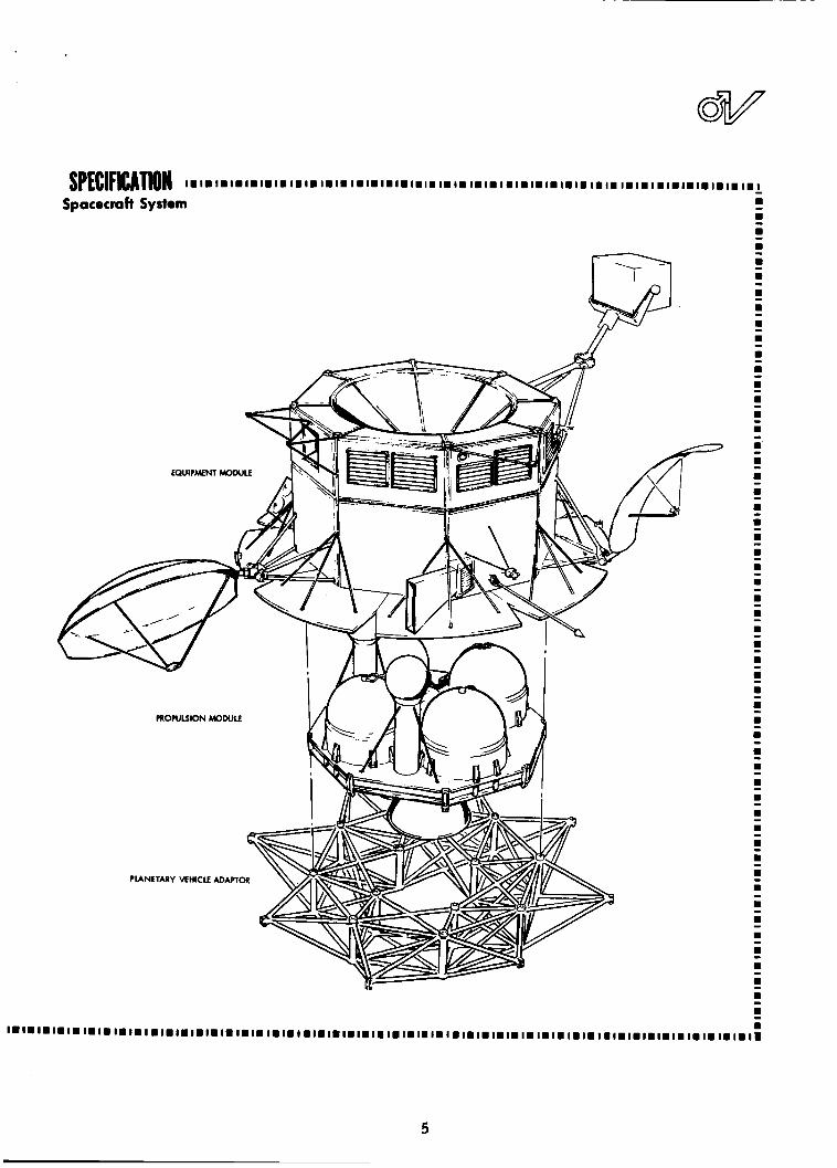
Structure: 3 modules: equipment module, propulsion module, ond planetory vehicle adapter; olumiwm franing and honeycomb deck; semi- monoccqve; meteoroid panels
Size of baric spacecraft: 14 ft, I i n long; 19 ft, I O in diometel
Appendage Mechanization: Plmetory Scan Platform - double gimballed and limited range continuo~s deployment drive
High goin antenna -double gimbolled Medium goin ontenno -single gimballed Low goin ontennos (2) -deployed to fixed position
Weight
Coprule 5,000 5,wO 7,OW Spacecroft (inert) 5,444 5,513 5,516 Uwble p rwe l l nn t f 9,653 10,653 11,581
Totol Plonetory Vehicle 20,107 22,166 24,097
For minimum A V I .95 Km/rec
Recommended
Performance Characteristics TELEMETRY A N D DATA STORAGE
4 tape recorden store 9 x 10' bits each Central telemetry data handling unit plur IWWI rem9te multiplexer m i t i on Planetory Scan Plot:orm. Six tqpe 2 tope recorders store 7.5 x IO6 bits each
Tranmirrion in 32 6-bit biorthogonal code recorders. Flexible formot generotor
Video transmitted dpa t i ve l y between 51.2 ~ ~ ~ ~ r ~ ~ ~ ~ m e d Or progr"mr ond 3.2 kb/rec
Engineering data continuous at 512 bitr/sec Emergency Mode doto o t 8 bits 'iec
5-BAND COMMUNICATIONS
3.2degreer beom width Medium gain antenna: 28 db
dherical coverose.
COMMAND
Rote: 8 bitr/rec. Accepts up to 256 Redundant bi t rynchronizen ond decoder, cmmandr, processes serial data for 1 I on-bood dertinotionr
demodulotc and synchronize commands from S-bond radio.
4cguirition Time: 2 minuter maximum
GUIDANCE AND CONTROL
L i m i t Cycle: 10.5 degree per o x i i Fully-rtobilized, 3-0xir control; (coast phorer) 10.25 degree per axis (photo-imaging and caprule reparation
Thrust Vector Control Accumcy: t0.43 degree per axis
nitrogen heated gar; wn and Cmop l r references; redundont inertial reference
COMPUTER AND SEQUENCER
l h e i discrete command and ~ e r i o l merrager for automatic on-bood cont rc l Computer pointing ongler for high gain ontenno ond Plinetary Scnn Plotform. Stover 51 2 %bit words.
Primory sequencer plur accelero- meter counten m d function generoton, with decoder i n
Backup sequencer. lntegroter accelerometer ovtputi during engine burn, giver cut-off.
Planetory Scan Plotform.
~
ELECTRIC POWER
Army Voltoge:
Array Power: 836 wotts at 1.62 AU botterier (48 amp-hrr)
Bur Voltage 50 VDC tl%
lndividuol DC DC c m v e r l e i r , (00 H r 12 oppendage driver, 819.2 K H z sync signal
37 to 50 VDC 226 rq ft fixed wlor ormy, three N iCd
- 10 subsystems
ELECTRICAL DISTRIBUTION AND PRYOTECHNIC CONTROL ~~
Distribution control uni t feedr DC power to 0 1 1 rubiyrtemr
Mort harnerrer removoble Pyrotechnic control
""81 operoter .I1 electro-explor,"er
PROPULSION
M a x . propel l in t load. 16,000 Ibr
PmpelImrr. N204 ond A . 5 0 or M M H
*SP Thrust - -
Main Engine 9850 lbr 298 iec 1700 ib i 289 iec
Backup Elginei 400 Ib, 292 rec
Toto1
M d i f i e d LMD main engine with tankoge identical far 0 1 1 mii i ion i , four C - l engine5 05
Outornotic backup for Mars orbit insertion to
ochieve reduced mirrion, moin engine glmbalied ond bock-up engine duty-cycle-modulated :ON th ivr t YeCto l C 3 " 1 1 3 1
TEMPERATURE CONTROL
Solo, Army iemperm,rer !4"eroge) - IJUY~II, ~ p e c i o l I Y ~ ~ O C ~ :inishe$
E h i l t i l o y e i ~ n d o l ~ u n , mdi\ iduol ly acfuoled
4nnular array
Bare army
Equipment pone1
Planelory Scan Platform 84 Intellor tempelolyie
4
I.I.I. .I. 1.1.1.1.1.1.l.1.1.1.1.1.
I I I I !
I I I I ! I ! ! I
! I ! ! I ! I ! I
I ! ! ! I ! I ! !
I I ! 5 I ! I ! I
! I I I I ! !
I -
8 -
8 -
I -
8 -
5

=SYSTEMS
22 APR
2 APR
? 13 MAF Q: n
. 2 2 Q
21 FEE
1 F E t
12 JAF
m h 0. - 23 DE(
ADDITIONAL WEIGHT IN MARS ORBIT, LB
I I (CASEA) I /
/ I
REQUIRED USABLE PROPELLANT, LB
10 000
20 -90 -60 -3 0
1 (CASE B) I 30 60 90
A+, APSIDAL ROTATION, DEG
THE PERFORMANCE CAPABILITY OF THE RECOMMENDED SPACECRAFT for a Type I trajectory to Mars in 1973 is displayed in terms of six variables that can be adjusted according to the goals of a given mission. On these charts two of the variables are held constant: in both charts the orb i t at Mars is assumed to be 1100 by 1 0 , m km: the chart at the left assumes a launch period of 20 days, that at the r ight 30 days. The curves then bound the capabilities of the spacecraft in the other fou r variables: mean arr iva l date, orbital change capability, required propellant, and payload weight, with payload defined as additional weight on the planetary vehicle beyond the Case A configuration. For example, on the left w i th in the sol id-l ine contour labeled 2ooo pounds are the options possible wi th a 7m-pound CaPSUle lM00 + 2ooo). In this case the position of periapsis of the orb i t can be altered 82degrees through a posigrade rotation ( + A+) from that provided by the min imum velocity increment at inser t ion or 112 degrees through a retrograde rotation (-A+). At the same t ime the mean ar r i va l date can be selected at any time from January 10 to
6

2 APR
13 MAR
W I- Q n 2 21 FEE - ’ x
4
5 : Z
z 1 FEB
12 J A N
m I\ 0’
23 DEC - 0 -120 -90 -60 -3 0 0 30 60 90
A+, APSIDAL ROTATION, DEG
Apri l 8, 1974. Since the 16,000-pound dashed-linecurve defines the upper l imi t of propellant capacity on the recommended configuration, the range of choices below that contour al l assume that amount of propellant.
On the other hand, i f the mission goal is in i t ia l ly established in terms of a selected arr iva l date and a desired amount of apsidal rotation, a point on the char t is fixed which defines the payload capabilityand the consequent amount of propellant required, For example, i f one wishes to be able to change the orbit orientation by -60 degrees (or equivalently +SO degrees) and arr ive at Mars on March 13, 2800 pounds of additional weight (e,g.. a 7800-pound capsulel and 12,825 pounds of propellant are therebyestablished,
As shown on the right, to plan the mission fo r the same orbit at Mars but with the greater flexibility of a #)-day lm n c h period reduces the range of the options. With a 7000-pound capsule, the arr ival date can be chosen between February 6 and March 12 and the orbit rotated in the range from 68 to -88 degrees.
7

TRWSYSTEMS
12 MAY
22 APR
2 APR
w ’ 13MAR 2 2 - t = I \ w 0 . 4 - Z 4 21 FEE 2
1 FEB
12 JAN
(? I\
0. 7
23 DEC -150 -120 -90 -60 -30 0 30 60 90
A+, APSIDAL ROTATION, DEG
THE PERFORMANCE CAPABILITY OF THE RECOMMENDED SPACECRAFT is f u r t h e r displayed by showing that if the size of the orbit at Mars is increased, the energy required for orbit injection is reduced and as a consequence more latitude is possible in selecting among other mission variables. As in the previous charts, contours a r e
a

2 APF
13 MAF
w I- Q n
Q * 2 2 21 FEE
A
2 4 Z
2 1 FEE
12 J A N
m
- 23 DEC
r. 0.
-
plotted for the two launch periods, 20 and 30 days, and the relationships among the options available in the other four variables are shown. Given an orbit of 1ooo by 20,oOO km. a 20-day launch period, and a planetary vehicle carry ing a 7000-pound capsule, the apsides of the orbit can be rotated 80 to -122 degrees, keeping the date of arr ival a t Mars constant around February 27, 1974. Alternately, the capability for altering the orientation of the orbit can be traded for early arr ival on January 10 (with 16,000 pounds of propellant).
9

-SYSTEMS
On the basis of this configuration, the char t s on pages 6 through 9 Contours of addi- i l lustrate the type of performance margins available.
tional weight o n these figures i l lustrate the range within which the marg in
can be devoted to increasing payload weight by reducing the a r r i v a l date
span and possible rotation of per iapsis in the orbit a t Mars . F o r an
orbit 1100 x 10, 000 km, the maximum additional weight capability of
5480 pounds is achieved with an a r r i v a l date of February 11, 1974.
These figures show that selecting an orbit with a higher ellipticity
resul ts i n a g rea t e r spacecraft capability since the velocity increment
for the orbit insertion maneuver is reduced.
ing for a longer launch period reduces spacecraf t capability since both
Cg and Vm a r e necessar i ly increased (for a fixed mean a r r i v a l date).
Analyses f o r 1975, 1977, and 1979, presented in Volume 2, show similar
performance margins available in these yea r s .
On the other hand, design-
The analyses include all energy requirements for miss ion success ,
including trajectory bias to mee t the Mart ian quarantine objectives.
means of such mission factors , control of the potential sources of By
MISSION TIME, DAYS
PROBABILITY OF SUCCESS of the recommended configuration i s plotted for the 1973 mission. Although the nominal transit time Of 205 days i s indicated, the reliability calculations are based on the upper-l imit t rans i t time of 224days i n 1973, introducing d Conserva- tive bias in to the results.
10

contaminated effluents, and well-planned safeguards during spacecraft
fabrication and assembly, the probability of contaminating Mars with
live t e r r e s t r i a l organisms is kept below the miss ion allotments, a s dis-
cussed in Volume 2 .
With the recommended configuration, the probability that one of
the two tandem-launched planetary vehicles en ters the des i red orbit at
M a r s and completes all of i t s objectives in that orbit is calculated to be
90 percent.
of success of 70 percent calculated fo r one spacecraf t .
As shown to the left this reliability is based on a probability
2.2 SPACECRAFT DESIGN
The recommended configuration provides modularity, good load
paths, fixed so lar -cell panels, and convenient, s t ructural ly sound
mounting and control of appendages.
modates the propellant tanks efficiently while retaining s t ruc tura l sim-
plicity and direct load paths.
fo r meteoroid protection f o r m the s t ruc tura l s ides of the spacecraft and
se rve as mounting surfaces fo r the astr ionics equipment.
The octagonal cross-sect ion accom-
On the equipment module s t ructure , panels
Structural Subsystem
Purpose Provider I ~ N U C ~ Y ~ O ~ intcgmtion, support ond environmental protection for the spocccmft subsystems and mounting provirions for the flight capulc.
SUBSYSTEM CHARACTERISTICS
The wbrystm is capored of on equipment module stwcture and propulrion module structure plus support and release rncchonirmr for oppcrdwr.
Characteristics Performance Characteristics LOAD FACTORS (LIMIT) LONGITUDINAL LATERAL
Primary ~tmctures Stotic Dynmic Static Dynamic ---- COMPONENl 1st stow burnout r5.0 a1.0
Pmpulrion module
1st stage cutoff 2.0
~
ItNCtWe Retrofire +2.0 t 0 . 3 FACTORS OF SAFETY
General SlNCturc 1 .@I 1.25 Equipment
METEOROID PROTECTION
Yield Ultimate
module ItNCtVlC
Spacecraft wrrfDce o m 6-50 quare feet
Mission time 284 days
Probability of ~ c m p n e t m t i o n Mission reli&ility Oqbs77 1 Subsystem
CONFIGURATION
3VERALL DIMENSION
158 in , OCIOII flats
quorc x 22 in. hi+ octognn toper to 57 in.
158 in. octqon x 100 in. high
Interfaces FLIGHT CAPSULE: 8 equdly y c e d bolts a n D 160 in. diameter bolt circle
PLANETARY VEHICLE ADAPTER: 12 points , 8 equally spaced on IM) in. diameter bolt C ~ ~ C I E 4 equally spaced on 80 in. dimetcr bolt circle
- “T 484 Ib
IW8 Ib
- 14921b -
MATERIALS A N D CONSTRUCTION
7075 AI built up beams plus honeycmb deck
?075 Al-remimmocoque plus rnctemid panels

12

Attached to the upper face of the gr id beams of the propulsion
module a r e honeycomb sandwich panels forming a platform on which the
tank sk i r t s a r e supported.
face of the grid assembly are mounted solar-cell a r r a y s , with four
tr iangular a r e a s available for growth in the power supply.
On the rectangular a r e a s of the lower s u r -
Activated by pyrotechnic release devices a t the attachments to the
adapter, a spring system impar t s a velocity differential to the planetary
vehicle for separation f rom the adapter.
off axis is statist ically small, even including c . g. offset effects, such
that simple ra i l s and followers a r e adequate to guide the spacecraft
f rom the shroud.
the four antennas and the planetary scan platform.
The net perturbation velocity
Pyrotechnic re leases are a l so employed for deploying
The spacecraft is designed so that there can be no unstable slosh
mode in the propellant tanks at any t ime in the mission, even if the cap-
sule must be separated before a r r iva l at Mars .
The Lunar Module Descent Engine, modified for two discrete thrust
levels, 1700 and 9850 pounds, is incorporated in the main propulsion sub-
system.
and for orbit adjustment at Mars ; the higher thrust is for orbit insertion
a t M a r s . A c lus te r of four C-i engines is a l so included, which, as dis-
cussed in Volume 3, can place the planetary vehicle in a highly elliptical
orbit of typically 1000 x 80, 000 km, permitting thereby a means of
saving the Voyager mission i f the main engine fails.
The lower thrust is for interplanetary t ra jec tory corrections
The guidance and control subsystem provides three-axis attitude
control of the planetary vehicle and spacecraft at all t imes af ter sepa-
ra t ion f rom the launch vehicle.
engine firing and senses the crossing of the Mars l imb and terminator .
In the guidance and control subsystem a proven design is used with full
redundancy of all cr i t ical components. In addition, the system can
operate in various alternate modes i f a component fa i ls .
It a l so measu res acceleration during
Immediately following separation of the planetary vehicle f rom the
S-IVB, the guidance and control subsystem reduces tumbling ra tes to a
low level (approximately 0. 01 deg/sec) to facilitate and prepare f o r com-
munication and prepare f o r operations following emergence f rom eclipse.
13

~~
Purpose To provide thrust 01 levels ond timer a required to occamplish the planetary orrival date reporation monewer, interplanetory tmjectov corrections, orbi t insertion, ond trimming of the ottoined orbit.
Perf orma nce Characteristics Total impulse:
Thmst levels
High: Low :
PERFORMANCE
4.82 x IO6 Ib/sec
9850 Ib 1700 Ib
M O W " " = , Nominal Thrust
Planetary orrival date
Orbi t insertion, start 9,850
seprot ion 1,700
Orbi t ~nsertian. end 10,ooo Orbit trim 1.m
SP Nominal I
298
305
303
289
Propulsion
Physical Characteristics
WEIGHTS, LB
Dry bmout without helium)
Prerruront (he1 ium)
Fuel (50-50 UDMH/N2H4)
Oxidizer ( N 2 0 4 )
PRESSURE, PSlA Helium storage
Regulator outlet
Propellant tank operating
Engine in let
Engine chomber
High thrust
Low thru,t
MISCELLANEOUS
Moximum engine gimbal ongle
Nozz le area ratio
Response, signal to 90% thwst
Engine mixture rot io (oxidizer/ fuel)
1565.2
1998.4
42.2
6153.8
9846.2
4ooo 249
235
220
100 18
* bo, 2 axis
47.5:l 0.25 rec
1.6:l
THERMAL REQUIREMENTS
Propcllont temperature Bulk temperature 70 f M°F
AT between unl ike pmpllonts, 5OF
AT between l i ke propellants, 2OF
70 f M°F Feed system temperature
Engine head end valve
Engine lnternol wrfacer expoled
temperature l i Q ° F mox, M°F min
to solor heat during c y c l e MOOF mox
ENGINE FLOW RATES, LB/SEC
M0"sW.Z' Nominal Thrust Flow - Rote
Planetory arrival dote seprotion 1700
Orb i t insertion, start
Orbit insertion, end
Obi: v i m
5.7
9850 32.3
1 o . m 33.0
I700 5.9
14

SPECIFICATION Subsystem
ITEM WEIGHT ILB) SYMM)L ITEM Q U A N T I PI PRESSURIZATION SYSTEM
Prerwrant t a k 2
Explosive valve, n o n o l l y closed Explosive valve, normally open 13 Fi l ter 3 Quad pressure regulator 1 Quad check valvc orwmbly 2 Bunt disc a d relief valve assembly 2 Pressure tronsducer 3 Miscellaneous hodwore and lines 2 Temperature transducers
ENGINE ASSEMBLY
Combustion chomber s i n b l y C h a b e r heot shield Seal Nozz le insulation Nozz le eitension H d W a r c Injector Pmpellont lines ond duch Control valve - h i g h thrust Contml valve - low thrust Hodware Trim orif ices Electrical homers Junction box H o d r a r e - J . B. I nStNmentOtiOn Gimbal assembly Pintle DClUatOr
202.5 8.0 2.0
26.5 36.0 5 .0
29.3 13.0 17.0- 13.8
0 . 5 6 .0 4.0 3.0 26. I 5.5 4.0
405.0
1156.8
0 . 8 \
- - -
PROPELLANT FEED SYSTEM
Propellant t m k Start tank assembly F i l l a d drain coupling Prevalva Stort tank control valva Pressure tronsdvcer Temperature transducer Mircelloneour hardwore Fuel l ines Ox id i ze r lines F i l t s o Electrical hamcrr Junction box
TOTAL DRY WEIGHT
I, 4 TOTAL
! 1 8 1 m IC I.
15

Entering sunlight, the pitch and
yaw axes stabilize with so la r
a r r a y normal to the sun.
is a l so a celest ia l reference f o r
maneuvers . The rol l axis stabi-
l izes with respect to Canopus.
This orientation is maintained
throughout interplanetary cruise ,
The sun
.
Guidance and Control Subsystem ~
Purpose The guidance and cmtrol ruaryrtem provider contitwous three oxis ottitude control of the planetary vehicle
Copability ,, prov,ded for reorientation ~n 0 1 1 thiee oxis ond far the measurement of incremento1 velocity ~n the thrurt o x , %
eithel a sun-canopus celei t iol reference ryrtem or on on-board inertial reference ryrtem.
~ _ _ _ _ An , n d ~ c a t ~ o n o f the crarring of the Mor, down ond evening terminator> i l provided.
Performance ATTITUDE CONTROL
Malnio,nr p o ~ ~ m n g occurocy of f 0 .6 deg, h e o c h a x i l w t h respect to celestial reference frame.
Orientl IO derired direction, provlder thrurt vector point ing occuracy of f 0.43 deg, 30 each oxis wi th respect to the celer l iol reference frome.
Photo-Imaging
Mointoini spacecraft point ing occurocy of f 0.35 deg, 2 each a x i l ond ongular rotex lesi than I O deg'hr.
Intertiol Hold
Provides for otlltude control using on-board inert iol reference wi th attitude dri f t leis than 0 .5 deg'hr.
VELOCITY MEASUREMENT PERFORMANCE
Measurer "elocity incrementi o f up to 3000 mrtety'sec with an accuracy of 0. I percent and wi th o resolution of 0.005 meted rec .
TERMINATOR CROSSING INDICATION PERFORMANCE
Provide$ on indication of the parroge of the sunlit portion of the Mon disc through o cone ongle of 90 degrees in the rpacecroft coordinote ryitem.
~~~ ~ ~ ~ ~
Physical Characteristics Weight: 279 Ib
Power: 205 wattr loverage during moneuve~i)
+ b
- ROLL
b CONTROL PITCH
COARSE SUN SENSORS REACTION
SYSTEM b YAW FINE
SUN SENSORS
ACQUISITION , SUN SENSORS
- 4
L MD ENGINE GIMBAL
ACTUATORS
-D GUIDANCE A N D CONTROL .
ELECTRONICS CANOPUS SENSOR b -
STAR ACQUISITION GATE .* PROPELLANT
VALVES 71 -COMMANDS --
PITCH, YAW . * -FROM COMPUTER A N D SEQUENCER
C - l ENGINES
I I INERTIAL IREFERENCE
To COMPUTER A N D SEQUENCER OMETER --- "EVEN I NG " TO COMPUTER A N D SEQUENCER El= "DAWN" TO COMPUTER A N D SEQUENCER
LIMB A N D TERMINATOR
CROSSING DETECTORS

excep during t ra jectory correction maneuvers . Before the main engine
is f i red, the spacecraft is oriented cor rec t ly in accordance with ground
commands previously s tored in the computer and sequencer and the atti-
tude i s verified by achieving communications on the high-gain antenna,
the antenna having been positioned before the maneuver.
reference fo r these operations is an iner t ia l reference unit, the elements
of which a r e initially aligned with the celestial reference f r a m e . After
each maneuver the c ru ise mode of operation is re-established. In Mars
orbit the guidance and control subsystem maintains three-axis stabil iza-
tion of the vehicle using again the sun-Canopus reference. Two Canopus
senso r s a r e car r ied , on opposite sides of the spacecraft , to allow rapid
roll orientation at Mars i r respect ive of whether the direction of the
spacecraf t in orbit is northward or southward.
be occulted, control i s switched to the iner t ia l unit until the celest ia l
references a r e again visible.
The attitude
Should the sun o r Canopus
The commands and control data for a complete miss ion a r e s tored
in the sequencer before launch. The subsystem can then program the
miss ion independently, using sensor outputs for control o r generation
Purpose Performance Characteristics Decoding: 256 discrete commands
13 oddrerrer for serial
12-bit serial words to ontenno 32-bit serial words to computer and sequencer
The command subsystem receives commodr from the S-band radio rub- system ond routes h e m to Spacecraft subsystems ond the capsule as directed by oddrerrer in the command doto.
messages
Physical Characteristics Total volume: 380 cu in.
Total weight: 10.5 Ib
Tatol power: 12.4v.attt
I I
SERIAL DATA TO COMPUTER A N D SEQUENCER A N D DIRECT TO ANTENNA CONTROL
!
t
t I
t t I t
t
I t
-- - - - - - - - ---a_-- - - -- t
t t t t
t t t
- DE C 0 DER S
+ DISCRETE
-* TO COMMANDS
SUBSYSTEMS
OUTPUT DECODER
- -
I 1------ ------ I CHANNEL A
CHANNEL B
FROM RECEIVER _ _ - ------- -- ---- ----
8 - 8 OUTPUT
DECODER -
17


modulated onto a 512-Hz subcar-
rier, while the ranging data is
transferred to a modulation com-
biner where it i s filtered and
combined with the downlink data.
- m - I I
I I I I I I
I I I z I !! I I I
I I I I !!
I !! !! I I I I I I
I I I I I I I I I
I I I
-
-
- -
8 -
-
8 -
S-Band Radio Subsystem
Purpose I Physical Characteristics The S-band radio wbryrtem provider reception and demodulotion of commond ond ranging doto from the DSN ground riotions ond tronmisiion of telemetry dola and ranging from the spacecroft to the ground station. The rubryrtem olio provider f o r o doppler frequency shift meowrement by tronrmitting o corrier frequency coherently related to the received uplink irequcncy.
Performance Characteristics
Weight:
5-bond electronics 68.6 povndi
Antennor and driver 135.6 pounds
Power:
S-band electronics 180 watts max
Antennor and drives 60 watts peok
RECEPTION:
Number of channels: Four (2 low w i n , 1 medium gain ond 1 high gain)
Frequency: 2110 - 2120 MHr
Receiver sensitivity: -149 dbm
Noise figure: 5 db moximum
Phose lock bandwidth: 32 Hr IF Bandwidth
r ideband channel: 2.5 MHz narrowband chonnel: 1 KHr
Receiver dynamic mngc: -149 to -50 dbm
TRANSMISSION :
Number of t ronmi i r ion channels: three ( I lm gain, 1 medium gain and I high goin)
Frequency: 2290 to 2300 MHr (coherent with uplink or optional intern01 cryrtol control)
High p w c r transmitter output: 50 watts minimum
Low power tmnrmitter output: 1 watt minimum
Transmission bodwidth: 3 M H r
ANTENNAS:
High Gain
Type: double gimballed circular probo lo id
Goin: 34db
3 d b beamwidth: 3.2degreer
Medium Goin
Type: single gimballed el l ipt ical paraboloid
Gain: 28 db
3 db beomwidth: 4 degrees by IO degrees
Low Goin
Type: four arm conical spiral
Gain: + I db
3 db beamwidth: 180°rninimum
FROM TELEMETRY SUBSYSTEM
B b/sc CHANNEL 2048 Hr SUBCARRIER
512 b/iec ENGINEERING DATA ( I ,024 MHr SUBCARRIER)
SCIENCE DATA (51 2 kb/iec MAX) I
HIGH G A I N ANTENNA
MEDIUM G A I N ANTENNA
LOW G A I N ANTENNA
ANTENNA RECEIVER DIPLEXER
- I I
I I I I r I I I I
I I
I I I I I I I I r ! I I
I I I I I I r I I
I I z !! I I I I !!
8 -
-
-
-
m -
- m

+
The link supports 8 bitsfsec com-
mand data through the omnidirec-
tional antennas with adequate mar - gin during the entire mission.
The command link is an adaptation
of the proven Pioneer system offering simpler hardware, shorter
acquisition times, and higher bit
- 8 - I I ! 8
8 - - I I I I
I I I
8 -
8
8
8
- - - I I !
I !
I I I
I I
I ! I I I I
! I
I
8 -
I -
8 -
8 -
8 -
8 - 8
8 - - I ? ?
I I
-
Purpose Fomm ond codes doto I m m the iclence payload and mcoruring p m l s in the spocccroft lor digital tronmiition by fhc 5-bond cmmunicofioni r y i r r m ~ ~ i f ~ c o l opcmtioni or when dofo m e is higher than communication link con hondk
Store this dolo during
Performance Characteristics BIT RATE SIZE, WEIGHT AND POWER (EXCLUDING TAPE RECORDERS)
Cmtrol dcmetn/ doto hodling unit
Sire 480 ~n (IO x 8 x 6 m.1 ( k i n C.rricr) Spl,t phose 51.2 kb/mc
25.6 kb/sac 12 8 kb/icc Weigh, II Ib 6 4 kb/rsc 3.2 kb/wc Power 6 wol t i
(Subcarrier)
fm.rg.ncy 8 b/rcc
S<,."C. 8 bits fngin"rin9 6 bifs Video 6 bill Sire 4 0 i i n . 3 ( 4 x 5 x 2 i n . )
Progrommobl. for engineering and science Powc. 2 wo111
Rcmole science multiplexer (locoted on PSP) Normal 512 b / h Sme 20 i n . 3 ( 4 " 5 x I i..l
Weight 2 Ib Pax., YM mw
ENCODING ACCURACY
Remofc photo-:magtng multip1ax.r (locoted on PIP)
DATA FORMATS Weight 2 Ib
Fired I r m e size for rid-
TYPES OF DATA INPUT OuTwT Analog LO 10 5 mlli) Biorfhogond block c d d c DiX,.,* Mod"l0,iO" Dig,t.l, Bidlare (Sut€.rric,)
STORAGE Split phase (hi" C.nicr)
Video dolo recorden 3 . 6 x IO9 bits (4 recoden)
fngine-ring o d ~cisnce recorders I .5 x 108blti 12 r.cord.nl
ENGINfERING DATA 512 AND 8 B/SEC I
TAPf RECORDEll_NO. I r , Y A k C R z smYsr tMs 1 I 1 DATA ENG1;f-l fNCODER
L---d - 1 7 5 x 10'8lTS 1 ENGINEERING
DATA fNCODER
1 r--- I
TAPE RECORDER NO. 4 I MfDlUM I RESOLUTION
TV I
? TO TRANSMITTER
VIDEO DATAfNCODERNO. -
TV IWKB/SfC VIDEO I RESOLUTION
* REMOTf TV
WLTlPLEXfRS MOUNTED IN
I
RECf IVER PSP ENGlNfERlNG
511 VSEC r--
RfCEIVER
- I !
I I I
8 -
8
8 - - ! I I I
I I
8 - 8
8
8
- - - I I ! I
I
I I I I
I
8 -
8 - - 8 - !
I I I
! I 5 I 2 I I I I
8
8 - -
8 -
8 -

ARRIVAL EARLY
DATA RATE VERSUS TIME shows variation in data rate capabilily as a function of time for the 1973 mission. The three curves indicate the achievable tiata rates for: ( 1) nominal l ink erformance ( 2 1 the RMS of the negative l ink tolerances and (37 the sum of the n e ative link tolerances. The horizonti! l ines indicate the.ava.il- abl! transmission rate as a function of time. The communication distances for an early a nominal and a late arrival at Mars are shown on the abscissi.
N O M I N A L l 9 0 X l&mJ 1974 DATES
LATE 2 4 0 X l&m
r a t e s than the older Mariner system. Any t ransmi t te r can be connected
to any antenna through circulator switches, providing a versa t i le means
f o r adapting to any component failure.
adopted for communications i s selected, over n o r m a l modulation, since it
m o r e than doubles the link capacity while st i l l relying on proven compon-
ents . As shown above, the communication link can support an average
data ra te in excess of 60, 50, 30 kbits /sec depending on range at e n -
counter. The 8 b i t s / s ec downlink is normally required only during r e -
orientation maneuvers when the high- and medium-gain antennas do not
point at ear th .
e t r y to ranges that encompass late encounter distances.
The (32,6) biorthogonal code
The link can a l so be used for low-rate engineering t e l e m -
The te lemetry and data storage subsystem takes data f rom the
science subsystem, the capsule, and the diagnostic measuring circui ts
(engineering data) and converts it into digital form, to be t ransmit ted in
rea l - t ime o r s tored on tape recorders for l a t e r playback. Tape s torage
is used as a buffer whenever data is generated fas te r than the communi-
cations rate. During descent of the capsule, its formatted TV and engi-
neer ing data is received via the U H F link and ei ther s tored o r direct ly
r e t r ansmi t t ed to earth.
mi s s ion r a t e s a r e furnished.
handling unit is supplemented by two multiplexers on the planetary scan
Programmable data format and seven data t r a n s -
The versat i le centralized te lemet ry data
21

Mo H I CONVf"7Fl
platform. The central unit i s
readily programmed for changing
data requirements.
The maximum power demand
for the recommended configuration
is calculated to be 808 watts, in
Mart ian orbi t a t 1.62 AU. At that
t ime the so la r a r r a y can deliver
836 watts, a s shown on page 23. A power control unit, specifically
adapted to the Voyager missions, regulates so la r a r r a y and bat tery power.
The control unit boosts line voltage ea r ly in the miss ion and reduces it slightly l a t e r on so that the a r r a y operates near maximum efficiency during
the cri t ical phases of the mission, a t the grea tes t ranges f rom the sun.
Conversion losses a r e accepted when grea te r power is available near ear th ,
in trade for t h e g rea tes t efficiency at Mars .
a r e a lso suited to the Voyager miss ion because of their g rea te r ability to
recover f rom the discharge-charge cycles encountered during Mar t ian
eclipse seasons.
Nickel-cadmium bat ter ies
Electrical Power Subsystem
Performance Characteristics Main 8"s Voltage
Solor Array Power
37 IO M v o l l i D C
I 67 ou 707 w I 62 ou 036 w I 00 ou I426 v
Battery E n r g y 1960 watt-hours
4W HZ Two-Phase for Anfenno and Planetary Scan Plotform Driver
Synchronization signal (Clock)
50 v RMS f 2%
819 2 LHz
Physical Characteristics
Subsystem weight 443 pounds
Solor Array Area 226 square feet
Components 44,640 N - O N - P Solor Cells
Three 16 Ampre-Hour Nickel-Cadmium mtterie,
Power Control Unit
400 t ir inverter
DC-DC Converten
POWER C O N T R O L UNIT
TRANSIENT L O A D BUS
22

AVAILABLE POWER 0 SUN OPERATION
SOLAR ARRAY -=I BATTERY OPERATION
BATTERY .......... I[IIIIIID BATTERY CHARGING
984 ....................................................... 984 POWER ..... 984 ........ -5. .................... (WATTS) i -sz;
PRELAUNCH, CRUISE TRAJECTORY CRUISE ORBIT ORBITAL ORBIT TRIM CAPSULE ORBIT TRIM SUN ECLIPSE LAUNCH, ETC CORRECTION INSERTION OPERATION (I) 150 MINUTES (MAXIMUM) ( I 2 0 MINUTES) ( Izo MINUTES) (120 MINUTES) (120 MINUTES) (120 MINUTES) (MAXIMUM)
ORIENTED 138 MINUTES SEPARATION (2)
POWER REQUIREMENTS for operation of equipment and battery charging are matched by power available, with substantial margin, throughout the mission.
Solar I Array I \
Purpose The solar a m y fits we l l w i th in the launch vehicle h r w d and provides growth potential of &bout 300 watts at 1.62 AU by f i l l i n g empty panel areas.
Performance Characteristics Power output at 1 AU 1426 watts
pwer d I .67 AU 787 watts
Total area 226 sq ft
Total weight 217 Ib
Voltage at 1.67 AU 52.0 volts N- on-P.2~2 cm 7 to 14 ohm-cm
Cel l type
- !
I
I I I I
I I I I
-
-
- - I !! I I I I z z
5
I 5 z I
5 m
- -
8 - -

IO0
0
L
. -100 m
c 3 Q g -200 w r
-300
-400 o 0.4 0 . 8 1 . 2 1.6 2 . 0 2 . 4 2.8 TIME, HR
THE COLDEST TEMPERATURES DURING THE VOYAGER MISSION occur at the endo l the 2 .6 hr Mart ian eclipse.
The coldest t empera tures in the
mission occur during solar eclipse
at Mars , the longest of which is
anticipated to l a s t 2.6 hours. In
eclipse for that long, the tempera-
ture of the most cold-sensitive
elements remains within safe
l imits. Engine firing produces
the highest temperatures; the first
midcourse correct ion is the upper
bound. Here again, all heat-
sensitive components a r e kept well within their respective l imits except for the base-mounted solar a r r ay ,
which briefly overheats 50°F above its nominal upper limit of 250°F.
considerable experience with solar a r r a y s has shown that such brief thermal
excursions a r e harmless .
TRW's
2.3 SCIENCE
For the recommended spacecraft a l l of the senso r s in the science
This platform i s payload a r e contained in the planetary scan platform.
designed for flexibility, adapting to a theoret ical 400-pound payload, the
500-pound hypothetical payload defined by MSFC guidelines, or even a
l a rge r payload carrying additional instruments .
craf t can accommodate senso r s mounted on the equipment module o r on
booms deployed from that module to provide additional flexibility in
orientation and reduce the possibility of effects of the spacecraft on
senso r s .
Moreover, the space-
The planetary scan platform can be controlled in two basic modes:
a closed loop mode controlled by e r r o r signals f r o m the M a r s t r acke r ,
and an open loop mode commanded by the spacecraf t sequencer .
e r r o r analysis (discussed in Volume 5 ) indicates that the platform can
be pointed with an accuracy of t 0 . 4 5 - degree during open-loop.
The
Electrical cabling between the instruments and their supporting
equipment in the spacecraft is reduced by two mult iplexers in the plane- t a ry scan platform. One multiplexer, under the control of the flexible
24

Hypothetical Science Payload
STRUCTURE EXPERIMENTS
Weight: 1831b
Strength: Designed to withstand Mors orbit insertion G loodt wi th PSP deployed
Front foce or-: 45 i n . x 37 in.
Volume: 34 cu f t
Deployment: electric hinge axis drive, explosive release from stowed position
High resolution IR Spec tmc te r
IR Spectmeter
IR Rodiometer
UV Spectrometer
Photo-imaging h/ltnn INTERFACES
Spacecroft StNCtVre: 3 Support StNtS T H E R M 1 CONTROL
Doto handling: Through remote mul t ip lexen in PSP
Computer ond sequencer: Through remote decode- in PSP
power: ~h,,,,$ rcmOte
Insulation: Fom within meteroid protection honeycomb p a r d s
Thermostats ond heatcn: For cxp r imcn t r and drive mechanisms
Cootings: Block Cot-a-lac paint except white I l l R I 2-93 on cml ing rodioton
Radiation: 3/16 oluminum plates for IR Spectnmetcrs
Cyrogenic refrigemtor: For broodbond IR Spectrometer
orrembly in Plomtary PIDtfon
34.6 watts for noneclipre orbit
55.43 wotts for c c l i p e orbit
P O I N T I N G A N D CONTROL
Pointing accurocy: 0.3O(Mon lemon -closed loopmode)
Control rates: 110 mr rec t o . 17 mr rec
Rcl iobi li ty : 0 .955
25

format generator, samples science data. The other samples and
formats photo-imaging data.
The sensor fo r tracking Mars is a modified version of the horizon
sensor used on the Orbiting Geophysical Observatories , with a spec t ra l
passband a t 18 to 3 5 microns . Three dr ives on the shaft of the platform
provide three degrees of freedom, although in one plane gimballing i s
l imited by the body of the spacecraft to an a r c somewhat l e s s than 180 de-
g rees .
to allow positioning the main shaft perpendicular to the plane of the orbit .
The other two orthogonal gimbal dr ives point the sensors a t the planet,
one dr ive rotating the shaft axis and the other the yoke axis . The same
wabble gear drive i s used on the shaft axes of the planetary platform a s
on the antennas to provide the developmental and testing benefits pos-
sible with commonality of equipment.
One drive is used for initial deployment and insofar a s possible
The platform and all supporting equipment within the spacecraft
have been designed in the expectation that the experiments c a r r i e d will
not necessarily be identical to the payload considered h e r e . To a s s u r e
flexibility a variety of other experiments has been evaluated, conceived
as mixed with the hypothetical set o r a s substitute experiments ,
adaptability of the spacecraf t to nine other instruments is discussed in
Volume 5.
2.4 GROUND EQUIPMENT
The
Three types of ground equipment have been designed as an integral
par t of the spacecraft sys tem design process : the mission-dependent
equipment, the electrical , and the mechanical operational support equip-
ment.
requirements of the ground network supporting Voyager and the e lec t r ica l
checkout gear, six major i t ems have been identified as common to the
two uses : the command generator , the power supplies, demodulator -
synchronizer, biorthogonal decoder, data fo rma t genera tor , and the video
reconstruction equipment. As the design of the spacecraf t sys tem is r e -
fined, it is possible that additional items of mission -dependent equipment
can be defined a s identical to those in the sys t em test complex. appears desirable to have commonality o r at least p rogram compatibility
By defining in prec ise t e r m s the substantial overlap between the
It also
26

I
r 1.
t

: I I I I L19119 9 1 9 1 . 1 1 9 1 1 9 1 9 9 9 9 1 1 1 9 1 1 1 1 1 1 1 1 1 99911. t t t
t t
t t
I 9 9 9 9 1 1 11.9.11119.1111199191111119999999911. I I l e-
I I I I
I I I
a
L: 2' 3.
0. E '
m . A I
z:
4
28

I I
u Y 'A
2 t m
t I i . I
29

-SYSTEMS
I t
I t
I t
c
VI VI al u 0) L:
0 2.
CT e % 5 al
I .- VI al
U A U
c 0
c
-
.- w m
E 2 .-
c 0 U al U
U c m
VI
c 0 .- c E x 0
VI al
U c m
A
w
c
- n E, VI VI
L c
m 0
F 3
.- E 5
c VI
w .- c a2
r
3 VI - 3 .- c: m c U
E E m I V z 3 4: --I w I I-
+ 4

between the computer in the system t e s t complex and the computers in
the Deep Space Network.
The design assumes that the mission-independent equipment at the
ground stations and the equipment f o r the Voyager capsule and surface
laboratory a r e shared, constituting an integrated program capability.
The spacecraft mission-dependent equipment is sized for simultaneous
operation of two planetary vehicles, providing a ground operational sys -
tem capable of supporting al l of the tracking, telemetry, data processing,
and display and command generation and verification requirements .
plan for incorporating Voyager-peculiar equipment into the ground sys - t ems is shown on page 27 .
The
The mission-dependent computer programs a r e designed to permit
efficient monitoring of the performance of the spacecraft; processing and
correlating of information for engineering evaluations and operational
decisions; evaluating the implications of a l ternate courses of action; and
implementing the selected course of action. The programs, defined in
Volume 7, a r e a l so designed to be utilized for preflight mission planning
and feasibility studies, for training, and for operational readiness t e s t s
and sys tem checks.
The support equipment f o r system level testing of the spacecraft
is embodied in the system test complex, a simplified block diagram of
which is presented on page 28.
cation and design of the mechanical support equipment has occurred in
conjunction with the analysis of logistics for the Voyager spacecraft sys - t em.
application is exemplified on pages 2 9 and 30.
As discussed in Volume 7, the identifi-
A l l ma jo r i t ems for mechanical support have been defined; their
2.5 DESIGN AND OPERATIONAL ALTERNATIVES
In reaching decisions concerning both the general approach to the
recommended configuration and the specific components and assemblies
incorporated in the subsystems , tradeoff evaluations of competitive a l te r - natives have been completed.
recommended design is presented throughout the report where the specific
choice is defined, and Volume 6 evaluates the alternate approaches that
have been studied for the overall configuration.
t o an a l te red miss ion profile a r e also shown.
The rationale behind the choices in the
The means fo r adapting
31

-SYSTEMS
Beyond these , however, the study h a s brought into focus four
m a j o r design al ternat ives which c lear ly warran t fur ther study.
concluded that a photo-imaging sys tem modeled af ter that of the Lunar
Orbiter has advantages over the all- television system, advantages both
in planetary coverage and in data s torage requirements . This a l te rna-
tive is discussed broadly in Volume 5 and in detail in Volume 11.
appears fur ther that the operating al ternat ives of the C - 1 engine c lus te r
e i ther as a redundant propulsion subsystem o r as a means of enhancing
the versati l i ty of that subsystem need additional study,
is needed to evaluate the level of pressurizat ion maintained in the pro-
pellant tanks as a factor in the possible violation of the Mart ian quaran-
tine through meteoroid-induced explosion of the tanks. Finally, it is
concluded that a central ized, general-purpose computer i n the space-
c raf t has potentially far-reaching implications on miss ion success .
operational capabilities of the spacecraft and the potential f o r enhancing
the inherent flexibility of the miss ion by means of such a computer
warrant thorough study. In Volume 4 is presented the f i r s t s t e p toward
evaluating the implementation of a computer, the investigation of digital
control systems.
It is
It
Additional study
The
The Agena and Transtage engines have been evaluated for the
To that end the Voyager spacecraft with respect to mechanical f i t .
Agena engine (Bell Model 8 5 3 3 ) and Transtage engine (Aerojet Model
AJ 10- 1 3 8 ) were reviewed with respect t o the following:
0
0
0
0
Mechanical interface
Clearance of engine gimbal and head end assembly
Propellant line interface and l ine routing
Structure to dis t r ibute loads f r o m engine to spacecraft
F i t within the s ter i l izat ion can i s t e r
Electr ical interface
Thermal control of engine
It is shown that the Agena will f i t within the spacecraf t . The only modi-
fication is to the spacecraft t r u s s m e m b e r s that dis t r ibute the load f r o m
3 2
,

the engine interface to the main module s t ruc tura l members .
the gimbal location the same a s that of the LMDE, minor repackaging of
the Agena accessor ies is required around the chamber . The Transtage
layout study indicates that it can also fit within the Voyager spacecraf t .
As with the Agena, the only modification is to the t r u s s m e m b e r s that
distribute the loads f rom the engine to the spacecraft s t ruc tura l m e m b e r s
The gimbal is located 10 inches aft of that of the LMDE, to permit the
most efficient engine supporting s t ructure , but remains within the enve - lope of the spacecraft and sterilization canis te r .
To keep
2.6 ADAPTABILITY AND GROWTH POTENTIAL
One of the principal c r i t e r i a applied in designing the spacecraft
for the 1973 mission has been its adaptability for other missions and its
potential for growth to l a rge r payloads and m o r e demanding performance
AS discussed in Volume 6, the recommended configuration i s adaptable
without change to capsule weights of 5000, 6000, and 7000 pounds and to
the energy requirements of the launch opportunities through 1979.
can equally well c a r r y a complement of experiments calling fo r sensors
mounted on booms o r the surface of the spacecraft a s well a s in the
planetary scan platform and can mount a subsatellite for par t ic les and
fields measurements .
It
The potential for growth in the configuration has been evaluated by
posing an upgraded spacecraf t capable of carrying up to an 8000-pound
capsule and 600 o r more pounds of science payload, as outlined on the
following two pages.
while retaining the adaptability for different mission years , proved to be
relatively minor.
panel in the equipment module which is empty in the recommended config-
uration. Solar-cel l panels a r e added to the four tr iangular surf aces adja-
cent to the a r e a s on which panels are mounted on the recommended
configuration.
The amendments to meet these added requirements,
The additional electronic equipment is mounted on a
To obtain higher data r a t e s , the 9. 5-foot antenna is replaced by
a parabolic reflector with a 238-inch d iameter , with a hole cut f rom its
center to pe rmi t stowage without interference with the engine nozzle,
and 100-watt traveling wave tube amplifiers are substituted for the
50-watt amplif iers . Since the narrower beam of the enlarged antenna
33

-SYSTEMS
m
m ! 1-e .
PRELIM IN ARY Upgraded
Physical Characteristics Structure: 3 modules: equ:pment m & l e , ~ m p l r i o n module, and p lamto ry
75 aluminum f ran ing ond honey- vehicle adapter (nat shown). c m b deck; Kmimomcoqus; meteroid panels.
Appendage Deployment: PSP high ond medium gain antennas deployed by wobble gear mechanisms
System Re l iab i l i t y : 0.66 for 6800+lr mission (224 days interplanetary, 60 days Man orbit) Size: (Foldad) 14 feet, I inch long x 19 feet , IO inches wide
(Deployd) 21 feet, long x 43 feet, 4 inches wide
Science Payload: 600 Ib ( in PSP, on hi, and bodymounted)
Capsule Capacity: Accommodates 8,ooO I b lor a l l missions, 1973 through 1979
Hordrore a d Tonkoge: Ident ical lor a l l 1973-1979 missions
Weight: Weight : (8ooo Ib capu le ) Equipment module 3 , 0 9 5 . 6 Ib
~ r o p u l s i o n module 18,330.4
Planetary vehic le 6 8 5 . 5 adapter -
Total 30 ,761 .5 Ib

Spacecraft
Performanco Characteristics
I TELEMETRY AND DATA STORAGE
2 tope r e c o d e n store 7.5 n ID6 each Central tclcmctrv doto handlina unit
Tmnsmitted in 16/5-bit biorthogonol code
Video transmitted adoptively 307.2and 19.2 kb/sec
between
Engineering doto at 512 bity'sec cont iwous
plus two remote diplerers on PSP and one on Equtpnent Module. Flexible format generator selects programmed formats or progroms new f o n o t s .
1 S-BAND C O M M U N I C A T I O N S I
High goin antenna: 39.9 db A l l d ig i to l communications. Redundont Mcdivm goin ontenna: 28 db 100 wott TWT's. Four receiven, four
ontennos: high goin (M f t d io) , medium gain. two low goin giv ing complete sphericol coveroge
C O M M A N D
Redundant b i t synchroniren ond decoden demodulotc and synchronize commondi from S-band rodio.
Rate: 8 bits/*<. Accepts up to 256 commonds, processes seriol doto for 1 1 on-bood destinations
Acquisit ion time: 2 min
GUIDANCE A N D CONTROL
Limit Cycle: t0.2 axis (ctwise and orbit)
iO.43 degree per a i s (monevvering thrust vector)
t0.20 degree per axis (photo-imoging)
Ful ly-s lobi l izcd, 3 - 0 x i i control; nitrogen heoted g a ; sun ond Conopus references, redundant inert io1 reference
COMPUTER AND SEQUENCER
Primory sequencer plus veloci ty meter counten ond function generoton, w i th decoder in PSP Bockup sequencer
Issues discrete commondi ond seriol messages for w tomot i c on-bod control. Computes point ing ongles for h igh goin antenno ond PSP. lntegrotes veloci ty m e t e t outputs during engine burn.
ELECTRIC POWER
XM sq ft orroy generates lOW wot t i ot 1.62 AU. 37 to 50 VDC (unregulated) batteries to indiv iduol DC/DC conver ten. 400 Hz to oppcndoge drives; 4 .1952 M H r sync signol to rubsystems
300 5q f t (#xed solor arroy, three NsCd
ELECTRICAL DISTRIBUTION A N D PYROTECHNIC CONTROL
Dir t r ibut ion control unit feeds DC power to a l l subsystems. Pyrotechnic control unit opemtes 0 1 1 electro- e x p l o r i v s
PRO1
LMDE: Total impulse: 4 .82 x 106 Ib-iec
Thrust level : 9850 Ib (high)
Fuel: N204 ond UDMH
1700 Ib (low)
C - I : Specific t m p l r e : 292 sec
Thrust level : 1M) Ib eo
Fuel: N204 ond UDMH
TEMPERATl
Neor Neon Eorth Mors
Solar Array OF OF Temperatures (Avcroge) - -
Annulor orroy 125 -7
Bore ortoy 246 86 Equipment Panel 9 0 5 0
PSP Interior Temp 84 35
Al l harnesses removoble Flexible harness to experiment bmms
jlON
LMD m o i n engine with four C-1 engine bockupr Tonkage Gdcnticol for 0 1 1 m is ions.
CONTROL
M u l l ~ l o y e r ~ n w l o l ~ o n , ~ n d i v ~ d u o l l y octuoted louven, speciol finishes
D I D 1 D1 81.1 DIMID1 8181
3 5
D I D 1 8 1 8 1 8181.1 81.1

-SYSTEMS
cal ls for tighter l imit cycles on attitude control, to keep the ear th always
within the beam, increased consumption of reaction control gas is r e -
quired.
thermal radiation areas and the s ize of the thermal louvers; the total
insulated a rea decreases f rom 494 to 4 7 1 square feet, the total a r e a for
louver-controlled radiation increases f rom 35 to 46 square feet , and the
average power for hea te rs increases f rom 2 1 to 33 watts.
The only changes to the thermal subsystem are increases in the
The effects on sys tem reliability of these changes a r e negligible
except f o r the fact that the greatly increased information ra te , approxi-
mately 300 kbi ts /sec, makes it no longer pract ical to conceive of the
medium-gain antenna as backup fo r the high-gain.
3. IMPLEMENTATION
In general, the approach to the implementing activities for the
spacecraf t is to a r range them s o that the adequacy of the design is con-
f i rmed as early as possible and reasonable t ime is allowed for unpre-
dicted development problems.
is summarized on the next page, and their schedule is shown on the
following pages. Design reviews, sys tem type approval, and miss ion
acceptance review a r e anchor points in this schedule, as well as the
The relationship of the ma jo r activit ies
launch date.
0
0
0
Key features in the scheduling a r e :
Early design data f r o m development tes t is obtained by completing environmental t e s t s and integrating the engineering model units before final drawing re lease .
Early reliability data is obtained f rom engineering model and type approval t e s t s before proof tes t model testing. In addition, spacecraf t life testing is conducted f i r s t on the engineering model space- c raf t and subsequently on the proof tes t model .
Final design is verified by proof tes t model t e s t s s ix months before fl ight-art icle spacecraf t a r e committed to environmental t e s t s .
The success of the project implementation descr ibed in Volume 8
r e s t s strongly on the carefully planned and intelligent use of engineering
36

I
37

- F
hl F I
/s PI F. E
Cl
I
/I
I
- 1
IC
I( S C
(E
V
PI
I
:
- P 41 3 IC
IC
I C T
~
I I I
I
ONFIGUW MODE: NI
5 S f DELIVERIfS 1 1 1 ,, I 2 3
38

YSSION .EPTANCE lNlEW
FLIGHT UNITS FABRICATION
I I
'TM UNIT
CRUISE PHASE
ORBIT1
E TlONS
OPERAtlONS
39

models. In addition, the modularity of the configuration permi ts the
flexibility for incorporating additional developmental t ime, through
paral le l activities, if i t is needed. Treating the engineering models
(s t ructural , thermal, and full spacecraft engineering models) as a major
s tep toward the flight model entails the application of configuration con-
t ro l disciplines as soon as laboratory fabrication of these models begins.
The full approval cycles that a r e applied l a t e r are not applied at this
stage of development, but drawings, tes t data, and other design informa-
tion as it is revised i s fed immediately into the configuration-control
cycle s o that all changes can be evaluated at the hardware level.
At this t ime, as well, the controlled engineering models a r e used
with the initial developmental models of the ground support equipment so
that the two proceed toward final hardware as a sys tem and so that when
flight models a r e checked the support equipment is a l ready known to be
sat is f ac t o ry . Mor e ove r, in this enginee ring -model pe riod, de c ont ami - nation processes and requirements a r e instituted at appropriate points
so that by the t ime flight units a r e produced the E T 0 processes a r e
smoothly coordinated.
Confidence in the schedule r e s t s substantially on the fact that the
project proceeds through paral le l s teps to i ts goals, up to assembly and
tes t of flight hardware.
problems a r e uncovered and solved is thereby built into the project .
Even when sequential steps a r e unavoidable, as in assembly and tes t of
a flight spacecraft, work on the individual flight models is s taggered
and located in different a r e a s of the assembly building s o that isolated
difficulties on one model can have no effect on the o thers .
The ability to continue to move forward while
Establishing and checking of mission-operations equipment, p e r -
sonnel, and procedures is scheduled to begin ear ly in the project s o that
problems that m a y be uncovered in this a r e a cannot jeopardize the f i r s t
launch.
These elements of the implementation plan have been instituted
and evaluated now to a s s u r e that the schedule is real is t ic . Specific
decisions in many a r e a s of the project need fu r the r study, however,
although none of these a r e likely to affect schedules. Integration and
40
checkout of the planetary vehicle is shown to occur at Kennedy Space
Center, but it is possible that program benefits may accrue f rom sched-
uling this activity at the Huntsville facilities. The plan as now prepared
i s sufficiently versat i le to be modified in many such ways without a l t e r -
ing i ts validity o r significantly changing the flow of events.
Assuming the configuration of this report , ear ly development and
tes t programs need to be undertaken with respect to the cooling equip-
ment fo r a cryogenically-cooled IR spectrometer and the tes t procedures
bearing on E T 0 decontamination.
g ram proceeds subsystem design provides data for manufacturing plan-
ning, tes t planning, and the planning of spacecraft assembly and integra-
tion operations. Engineering model units, fabricated within the
engineering laboratories, confirm the subsystem design. A second
se t of engineering models is assembled into a spacecraft by the manu-
facturing organization to confirm tooling and manufacturing processes ,
The final s tep in subsystem development is the manufacture of tes t
a r t ic les to flight configuration f o r type approval tes t of the electr ical
units and the corresponding design verification testing and qualification
of propulsion, mechanical, and s t ructural hardware. This final s tep of
type approval takes place before flight unit fabrication begins.
As the spacecraft development pro-
Flight configuration ar t ic les a re manufactured and acceptance
tes ted for integration into the proof tes t model spacecraft , before a s s e m -
bly of the three spacecraft . After flight acceptance tes t , the three space-
craf t a r e delivered sequentially to the launch site for integration into
the planetary vehicle.
mission-dependent equipment a r e manufactured at a ra te of approxi-
mate ly one se t per month. Activation fo r Voyager of a station in the
Deep Space Network begins nearly a year before the first launch.
To support the mission operations eight s e t s of
41

4. ENGINEERING STUDIES
4.1 E T 0 DECONTAMINATION
If conservative assumptions a r e made, the cur ren t Martian quaran-
tine requirement for the Voyager program appears to cal l for a limit of
100 viable microorganisms per square foot of spacecraft surface.
achieve that goal appears in turn to ca l l for decontamination procedures
based on the use of ethylene oxide-Freon 12 ( E T 0 ) a s abiocidal agent.
procedures would significantly affect the program, calling for relatively
large increases in manpower, for longer schedules during fabrication and
assembly to allow for training and the E T 0 cycles, and for cer ta in faci l i -
t ies in the program that otherwise would not be needed.
To
Such
Although relatively little t e s t data i s available on the compatibility of
ET0 with the specific mater ia l s and components planned for Voyager under
the conditions applicable to Voyager, extrapolating the available data indi-
ca tes that there should be no ser ious problem in ma te r i a l and component
selection. In most cases , the use of sensitive mater ia l s and components
can be avoided and where this is not possible units can be sealed to prevent
contact of the sensitive component with ET0 during te rmina l decontamination.
Materials and components for Voyager that have been found to be
degraded by E T 0 have been identified and evaluated as follows:
Materials and Components of Potential Concern
Propellants
Lub r ic ants
W i r e insulation
Conductive adhesive
C apac it0 r s
Magnetic tape
Photographic film
C onclu s ions
Sealed f rom contact with E T 0
Alternates available for lubri- cants that are degraded
Alternates available for insula- tion that is degraded
Alternates available
Certain types of capaci tors must be avoided
Sealed f r o m contact
Sealed f r o m contact
The fact that the majority of the materials and components expected to be
used on Voyager have not yet been tes ted for compatibility with ET0
42

in Voyager-defined environments need not burden the project excessively
since qualification tes t s must be conducted fo r Voyager in any event.
Clean assembly is required to keep biological contamination of
the spacecraft acceptably low.
facility requirement.
and tes t and terminal decontamination. Class 10,000 clean rooms
appear to be desirable for all operations f rom unit assembly through
terminal decontamination.
extent what would normally be required fo r particulate contamination
control.
a r e a mobile E T 0 ca r t and an aseptic purge-gas cooling c a r t .
Such assembly represents a ma jo r
Also required a r e E T 0 facil i t ies for evaluation
The requirements do not exceed to any ma jo r
The principal equipment needed for terminal decontamination
Design requirements for the planetary vehicle compartment so
that it is suitable f o r terminal decontamination a r e the following:
0 Maintenance of positive p re s su re in the corn'- partment with steri l ized g a s until launch, calling for one-way aseptic pressure-rel ief valves
0 A smooth surface to minimize pockets of con- tamination and to a id in final surface cleaning
0 Sealed one-way ports for E T 0 sampling and contamination monitoring
Most of the existing facilities for E T 0 exposure have inherent deficien-
c ies , p r imar i ly in the a r e a s of instrumentation and control functions.
It is therefore essent ia l that suitable procurement specifications be
developed to satisfy the requirements of the Voyager program i f the
stringent decontamination goals a r e to be me t .
4.2 SHROUD SEPARATION
Venting of the shroud during launch can be handled readily for
Voyager, and the probabilities of shroud elements colliding with the
planetary vehicles when they separate can be kept below 10
placing any of these elements on a collision course with Mars .
recommended se t of vents for the different elements of the configuration
is sketched at the top of page 44, based on allowable pressure differentials
determined by strength and contamination considerations.
vehicles need to be guided during their forward separation following a
scheme such as sketched here.
-4 , without
The
The planetary
43

~RWSVSTEMS NOSE FAIRING SHROUD
VENT AREA = 3.0 F T ~
CIRCULAR OPEN I N GS ,
CENTER SECTION
(EIGHT EQUALLY SPACED (EIGHT EQUALLY SPACED VENT AREA = 1.5 FT s-IVB
FORWARD SKIRT EACH 8.3 IN. DIA) OPENINGS, EACH IN. DIA) VENT AREA = 2.4 F T ~
WPICAL BIOLOGICAL BARRIER CONTROLLED VENT AREA = 1.5 F T ~ (FOUR CHECK VALVES OF 8.3 IN.2 FLOW AREA EACH SYMMETRICALLY FLOW AREA EACH SYMMETRICALLY
PLACED NEAR POLE OF SPHERICAL BARRIER) PLACED NEAR APEX OF UPPER CANISTER HALF)
SHROUD VENTS are selected to maintain the min imum overpressure required to prevent contamination dur ing ascent without exceeding the allowable pressure differential.
I , I \ /
RAILS ON THE SHROUD ARE MATCHED BY FOLLOWERS ON THE SPACECRAFl to guide the planetary vehicle dur ing over- th~-nose separation.
44

4.3 TEMPERATURE CONTROL
The review of combinations of insulated and uninsulated enclosures
and passive and active techniques for radiation control has led to the
selection of a temperature control subsystem for the Voyager application
that combines passive and active approaches using the totally insulated
enclosure concept, thermal louvers, thermostatically controlled hea ters ,
thermal finishes, and varying degrees of s t ruc tura l thermal coupling.
Bimetallic-actuated louvers were selected as the p re fe r r ed louver sys -
tem because of reliability, lower weight, simplicity, and proven flight
performance. Various types of insulation (i. e . , crinkled aluminized
Mylar, Dimplar, Kapton) were considered, including attachment, over-
lapping, interleaving, and blanket s ize and contours. Multilayer c r in -
kled aluminized Mylar was selected because i t provides the best thermal
performance with minimum weight.
is Velcro tape.
The selected method of attachment
159 BTU/HR-FT~ ORBIT INSERTION 9850-LB THRUST FOR 380 SEC
HIGH SOLAR FLUX
MARS ECLIPSE 5 2.6 HR
6 BTU/HR-FT2 FROM M A R S AT 6000-KM$LTITUDE, 3 BTU/HR-FT AT 10,000 K M
INTERPLANETARY CORRECTION 1700-LB THRUST FOR 380 SEC
SUN
THERMAL CONDITIONS dur ing the Voyager mission vary substantially as solar energy decreases with range, the engine i s f ired under varying circumstances, and the spacecraft enters eclipse.
45

4.4 PLUME HEATING
Analysis of the temperature and p res su re dynamics fo r the LM
descent engine aboard Voyager shows that there a r e no a r e a s of plume
impingement on the spacecraft and that the f i r s t interplanetary t r a -
jectory correction is the upper bound hot condition.
ear th , steady-state temperature of the base-mounted so lar a r r a y is only
a few degrees under i ts 248 F limit, during the 380-second engine fir ing
the heat flux from the engine plume causes a short-duration excursion to
300°F, as shown below. Tempera tures to 300°F have been tes ted in the
course of the V e l a satellite program, demonstrating that the integrity
and functional charac te r i s t ics of the a r r a y can be maintained. During
M a r s orbi t insertion, t emporary temperature excursions are a l so exper -
ienced during the 380-second engine firing, as shown below. But since
nea r M a r s the steady-state tempera tures are relatively low, the rises
during engine firing are well within the allowable tempera ture ranges.
Since the nea r -
0
400 I
BASE-MOUNTED SOLAR ARRAY
Y 300 t -
ANNULAR I I
I 1 H I G H G A I N A N T E N N A p=ADv
IO0 I
PLATFORM , I --
I I I 1 1 I I ‘0 100 200 300 400 500 600 700
TIME, SEC
FIRST TRAJECTORY CORRECTION
300
BASE-MOUNTED SOLAR ARRAY I I
BASE INSULATION
w, HIGH GAIN ANTE,NNA 7\ I 0 --
100 I 0 100 200 300 400 500 600 700
TIME, SEC
M A R S O R B I T INSERTION TEMPERATURES
M A X I M U M TEMPERATURES RESULTING FROM ENGINE FIRINGS are ex- perienced at the first interplanetary firing since init ial temperatures are higher; although the thrust level is greater at Mars orbit insertion, the reduced solar heat leads to cooler temperatures during the firing.
46

4.5 PHOTO-IMAGING SYSTEM
Because of limitations of currently acceptable tape r eco rde r s , it
appears that fo r Voyager a mapping and reconnaissance sys tem using
film is preferable to a sys tem relying exclusively on television.
t ime t ransmission of TV-sensed imagery is generally impossible and
once the requirement fo r data storage is introduced, the advantage of
TV sys tems in providing video signals disappears. Rather those s y s -
tems having an inherently large storage capacity a r e advantageous,
leading to a preference for storing the information on film.
Real-
In the study, th ree general types of systems were considered. The
f i r s t is an all-TV system, conforming closely to that incorporated by
NASA in the hypothetical science payload. The second is that recom-
mended by TRW, a dual-framing film camera based on Lunar Orbi ter
concepts for medium and high resolution coverage, along with a TV
c a m e r a for broad low resolution mapping in color o r black and white.
The third consists of a dielectric tape c a m e r a fo r medium resolution
Photo-lml
Purpose Tu provide complete photogrophic coverage of the plonct Mars 01 low resolution ( I kilometer) in color, mapping of l o g e ore01 of Man 01 medium resolution (100 meten), .and imaging of selected orear ot h i $ resolution (IO meten)
LOW RESOLUTION CAMERA
Sensor - RCA 1-I/2 inch vidicon with slow $con target Field of View - 29 x 29 degrees Ground coverage - 500 x 500 kilometers (per frome) Nominal ground resolution - I kilometer Number of f rmer per o h i t (maximum) - 33 frmer ( I 1 color pictures) Photogrophy time/orbit - 48 min (maximum)
MEDIUM A N D HIGH RESOLUTION CAMERA
Sensor - Eatmon KDdok 70 mm f i lm comero
Medium High
Lenser- f . 1 . IC0 mm (4 inches) loo0 mm (40 inches) Formot 6 0 x M ) m m M ) x M ) m m
Ground resolution IC0 meten IO meters
Ground track length per orbit (maximum) 7553 kilometen Photography lime,’ orbit 48 min(maximym) 48 min (moximum)
Frames p r orbit IO IO
CAMERA EQUIPMENT MOUNTED O N PSP
Weight 220 Ib
Power 50.6 woth (averogc) S l Z e 1 4 . 7 f t 3
TOTAL SYSTEM LNCLUDING ONE TAPE RECORDER
Weight 238 Ib Power 58.6 w d h (overogc)
W
il.l.l.l.l. 1.1.1.1.1.1.1.1.1.1.I.I. 1.1.1.
ing System . - !
m - - ! 8
LOW RESOLUTION - TELEVISION CAMERA W EASTMAN KODAK
m - ! z
I ~ I ~ I ~ I ~ I H I ~ I ~ I ~ I ~ I ~ I ~ I ~ I ~ I D I.I. i m i m i r n ~ m ~ m ; W
47

-SYSTEMS
coverage along with the low resolution TV color c a m e r a which is common
to all three configurations. No high resolution camera is included in the
third system. The dielectric tape camera can in principle be fi t ted with
an imaging system of sufficiently long focal length to provide high reso-
lution ground coverage, but this is not an attractive approach because of
a resulting long exposure t ime and consequent severe image motion com-
pensation requirements. A high resolution TV camera as in the baseline
system could of course be added.
Purpose To provide medium ond high rerolution photogrophic coverage of the Mart ial rurfoce. Containr integral f i lm procerror ond dato readout ryrtem
Performance Characteristics SENSOR
Eartman Kodok f i lm c o m e r ~ modified to incorporate 40 inch and 4 inch focal length leniei , lncreared radiotion shielding, Improve, "Birnot" f i lm ond proce~roi
FILM FORMAT
70 mm (60 x 60 mml Type 50-243, length 100 feet (usable)
OPTICAL SYSTEM
Medmum Rerolutioir High Resolution
Lens - - Rrfractive Cotad ioptic E F - - 100mrnf2.8 1000 mm f 4 .0 Exporule - 10-140mrec 10-40 miec Frome Rate I frame 2 sec mox- 1 frome'2 sec maximum
,mum IMC None 5 percent
PROCESSING
Eartman (new) "Bimat", web opplicotion transfer type appraximately 2 5 ,ncher,/min speed
I20 feet,
READOUT
F l y i n g $pot sconner with opticol and mechanical scan chonoeable os bNt rote i s chanqed
Rote GRE compatible
I Physical Characteristics size 14 I t t 3 Weight 200 Ib (including iadmtion shielding)' Power 49.2 Wltt5 (average)
- PROCESSOR READOUT -
--< \ - CAMERA
MMUNICATIONS
LOOPER
'NOTE: The weight eitimote inckder 30 gm/cm2 of rodiotion shielding for the f i lm coiette, D t o l d o f 65 pounds reducer the effect of 1olor c o m i c rays to a low l e v e l , ~n the order of 2 or 3 rad per year. The predominont radiotion w i l l be goloctic comic radiat ion of high energy leve l . against which shielding 8 1 not effect ive The level o f this radiatNon i s ertimoted to be from 6 to 20 rods per yeor. 50 percent fog level on SO-243 f i lm
Thlr rhielding
100 rod c a v ~ e l
I m
Although TRW recommends the dual-frame photo-imaging sys tem
described in the accompanying prel iminary specifications, the spacecraf t
described in Section 2 has been designed to accommodate the hypothetical,
al l-TV system. Since that sys tem places a heavier demand on the space-
craf t , a more flexible spacecraf t results which can c a r r y whatever type
of photo-imaging equipment is selected.

CONCLUSIONS AND RECOMMENDATIONS
The Voyager spacecraf t configuration descr ibed in this report is
both technically feasible and readily implemented.
by a Saturn V, it can c a r r y capsules weighing up to 8000 pounds into
orbi t about M a r s and rapidly survey the sur face . It can a l t e r the period,
the line of apsides , o r the plane of i t s orbit as needed t o a s s i s t in recon-
naissance of the planet.
the launch opportunities in the 1970's.
Launched in tandem
No changes in hardware a r e needed for any of
Its communication link can t ransmit 50, 000 b i t s / sec during i t s
initial weeks in orbit , and this information can be devoted to mapping,
high-resolution pictures, the relay of measurements by the capsule,
rapid surveys of experimental results, o r any combinations of these,
as commanded f rom the ground.
The configuration adapts easily to growth either of the capsule o r
With a 20-foot antenna substituted for the equipment in the spacecraft .
the 9 . ti-foot high-gain antenna, a n information ra te of 300 kbi t s / sec can
be achieved.
These conclusions a r e made possible by the approach that the
spacecraf t be designed initially i n view of the requirements of adapta-
bility to the launch opportunities beyond the f i r s t and of growth in p e r -
formance capability as the program m a t u r e s .
on the design have resulted f rom this approach:
tanks of sufficient volume for the most demanding of the mission c i r -
cumstances that may occur in the 1970's and structuring the spacecraf t
to support the weight of the heaviest capsule that m a y be flown in that
decade.
in any way jeopardizing one se t of miss ion circumstances in favor of
another leads TRW to recommend the approach strongly, as a means of
providing the mos t versat i le and cost effective Voyager program.
Two significant effects
inclusion of propellant
The success during the study of applying this approach without
Tradeoff studies documented in the l a t e r volumes have led us to
favor the following specific approaches :
49

rRwsYsrEMs
0
0
0
Modular construction with distinct equipment, propulsion, and adapter modules for paral le l development, assembly, and t e s t
A photo-imaging sys tem modeled after the dual- frame film camera of the Lunar Orbi ter , to ease the data-storage problem
Integrated approach to ground support that places a grea t deal of identical equipment in the system test complex and the stations of the Deep Space Network
Biorthogonal coding of the te lemetry, to permit m o r e rapid data ra tes at given signal-to-noise ratios
Multiplexers in the planetary scan platform to avoid complicating the cabling that c r o s s e s the gimballed interface of the PSP with the spacecraf t
Power regulation that provides the grea tes t con- version efficiency at M a r s
Before the details of the spacecraft configuration a r e selected,
i t a l so appears desirable to conduct fur ther studies in three a r e a s :
The feasibility and application of a centralized, general-purpose computer in the spacecraf t
Evaluation of the operational applications of a c luster of four C - 1 engines in the propulsion subsystem
The quantitative effects on possible violation of the Mars quarantine requirement of the level of pressurizat ion maintained in the propellant tanks
50