1594a/1595a super-thermometer - flukeassets.fluke.com/manuals/159x____tgeng0000.pdf1594a/1595a...
TRANSCRIPT

1594A/1595A Super-Thermometer
Technical Guide
159X____tgeng0000
Fluke Corporation799 E. Utah Valley Drive • American Fork, UT 84003-9775 • USAPhone: +1.801.763.1600 • Telefax: +1.801.763.1010E-mail: [email protected]
www.hartscientific.comSpecifications subject to change without notice. • Copyright © 2008 • Printed in USA
Limited Warranty & Limitation of LiabilityEach product from Fluke Corporation (“Fluke”) is warranted to be free from defects in material and work-manship under normal use and service. The warranty period is one year(s) for the thermometer. The warranty period begins on the date of the shipment. Parts, product repairs, and services are warranted for 90 days. The warranty extends only to the original buyer or end-user customer of a Fluke authorized reseller, and does not apply to fuses, disposable batteries or to any other product, which in Fluke’s opinion, has been misused, altered, neglected, or damaged by accident or abnormal conditions of operation or handling. Fluke warrants that software will operate substantially in accordance with its functional specifications for 90 days and that it has been properly recorded on non-defective media. Fluke does not warrant that software will be error free or operate without interruption. Fluke does not warrant calibrations on the Super-Thermometer.
Fluke authorized resellers shall extend this warranty on new and unused products to end-user customers only but have no authority to extend a greater or different warranty on behalf of Fluke. Warranty support is avail-able if product is purchased through a Fluke authorized sales outlet or Buyer has paid the applicable interna-tional price. Fluke reserves the right to invoice Buyer for importation costs of repairs/replacement parts when product purchased in one country is submitted for repair in another country.
Fluke’s warranty obligation is limited, at Fluke’s option, to refund of the purchase price, free of charge repair, or replacement of a defective product which is returned to a Fluke authorized service center within the war-ranty period.
To obtain warranty service, contact your nearest Fluke authorized service center or send the product, with a description of the difficulty, postage, and insurance prepaid (FOB Destination), to the nearest Fluke authorized service center. Fluke assumes no risk for damage in transit. Following warranty repair, the product will be returned to Buyer, transportation prepaid (FOB Destination). If Fluke determines that the failure was caused by misuse, alteration, accident or abnormal condition or operation or handling, Fluke will provide an estimate or repair costs and obtain authorization before commencing the work. Following repair, the product will be returned to the Buyer transportation prepaid and the Buyer will be billed for the repair and return transporta-tion charges (FOB Shipping Point).
THIS WARRANTY IS BUYER’S SOLE AND EXCLUSIVE REMEDY AND IS IN LIEU OF ALL OTHER WARRAN-TIES, EXPRESS OR IMPLIED, INCLUDING BUT NOT LIMITED TO ANY IMPLIED WARRANTY OF MER-CHANTABILITY OR FITNESS FOR A PARTICULAR PURPOSE. FLUKE SHALL NOT BE LIABLE FOR ANY SPECIAL, INDIRECT, INCIDENTAL. OR CONSEQUENTIAL DAMAGES OR LOSSES, INCLUDING LOSS OF

iii
Table of Contents
1 Before You Start .................................................................................... 11.1 Symbols Used ............................................................................................................11.2 Safety Information ......................................................................................................1
1.2.1 WARNINGS .......................................................................................................................11.2.2 CAUTIONS ........................................................................................................................2
1.3 Authorized Service Centers .......................................................................................2
2 Introduction and Specifications .......................................................... 52.1 Introduction ................................................................................................................52.2 Specifications ............................................................................................................5
2.2.1 General ..............................................................................................................................52.2.2 Primary Specifications.......................................................................................................6
2.2.2.1 Resistance Ratio Accuracy.......................................................................................................62.2.2.2 Resistor Stability .......................................................................................................................62.2.2.3 Absolute Resistance Accuracy.................................................................................................72.2.2.4 Measurement Current Accuracy ...............................................................................................7
2.2.3 Ancillary Specifications .....................................................................................................82.2.3.1 Temperature Measurement Noise .............................................................................................82.2.3.2 Relative Measurement Current Accuracy .................................................................................8
2.2.4 General Specifications ......................................................................................................92.2.5 Applying the Specifications ..............................................................................................9
2.2.5.1 Introduction ...............................................................................................................................92.2.5.2 How the Super-Thermometer Measures ...................................................................................92.2.5.3 Example 1: Measuring an SPRT .............................................................................................102.2.5.4 Example 2: Calibrating an SPRT .............................................................................................122.2.5.5 Example 4: Measuring a 100 Ω PRT .......................................................................................132.2.5.6 Example 5: Measuring a 10 kΩ Thermistor ............................................................................14
3 Preparation for Operation ................................................................... 153.1 Unpacking and Inspection ......................................................................................153.2 Instruction Manuals ..................................................................................................153.3 Line Voltage and Fuses ...........................................................................................153.4 Connecting to Line Power ........................................................................................163.5 Placement and Rack Mounting ................................................................................16
4 Front and Rear Panel Features .......................................................... 174.1 Introduction ..............................................................................................................174.2 Front Panel Features ................................................................................................17
4.2.1 Measurement Inputs .......................................................................................................174.2.2 USB Connection ..............................................................................................................174.2.3 Front Panel Keys .............................................................................................................18
4.2.3.1 Front Panel Display .................................................................................................................19
4.3 Rear Panel Features ................................................................................................204.3.3.1 External Resistor Inputs ..........................................................................................................20
4.3.1 Scanner Connection ........................................................................................................204.3.2 Future Peripheral Connection .........................................................................................214.3.3 Remote Operation Connections ......................................................................................214.3.4 Line Voltage Connection .................................................................................................22
1594A/1595A Super-Thermometer
iv
4.3.5 Earth Ground Connection ...............................................................................................22
5 Menus and Screens ............................................................................ 235.1 Introduction ..............................................................................................................235.2 Changing Settings ...................................................................................................235.3 Password Protection ................................................................................................245.4 Menu Navigation ......................................................................................................245.5 Menu System ...........................................................................................................245.6 Measurement Screen ...............................................................................................25
5.6.1 Channel Measurement Display .......................................................................................265.6.2 Channel Summary Section ..............................................................................................265.6.3 Statistics Fields ...............................................................................................................275.6.4 Data/Graph Section .........................................................................................................275.6.5 Status and Alert Section ..................................................................................................275.6.6 START/STOP MEASUREMENT (F1) ................................................................................285.6.7 SHOW TABLE/GRAPH (F2) .............................................................................................285.6.8 RESET STATISTICS (F3) ..................................................................................................285.6.9 CLEAR GRAPH/CLEAR MESSAGE (F4) .........................................................................285.6.10 START/STOP RECORD (F5) ...........................................................................................28
5.7 Main Menu ...............................................................................................................285.7.1 CHANNEL SETUP (F1) ....................................................................................................29
5.7.1.1 ASSIGN PROBE (F1) ..............................................................................................................295.7.1.2 CHANNEL SETTINGS (F2)......................................................................................................30
5.7.2 PROBE MENU (F2) ..........................................................................................................345.7.2.1 ADD PROBE (F1) ...................................................................................................................345.7.2.2 COPY PROBE (F2) ..................................................................................................................365.7.2.3 EDIT PROBE (F3) ....................................................................................................................365.7.2.4 READ PROBE (F4) ..................................................................................................................375.7.2.5 MANAGE PROBES (F5) .........................................................................................................37
5.7.3 MEASURE MENU (F3) .....................................................................................................385.7.3.1 SCAN SETTINGS (F1) .............................................................................................................395.7.3.2 TIMING SETTINGS (F2) ..........................................................................................................395.7.3.3 DIGITAL FILTER (F3) ...............................................................................................................415.7.3.4 RECORDING MENU (F4) ........................................................................................................415.7.3.5 ZERO-POWER MEASUREMENT (F5) .....................................................................................43
5.7.4 DISPLAY MENU (F4) .......................................................................................................465.7.4.1 USER SETTINGS (F1) .............................................................................................................475.7.4.2 FIELD SETTINGS (F2) ............................................................................................................485.7.4.3 STATISTICS SETTINGS (F3) ....................................................................................................495.7.4.4 GRAPH SETTINGS (F4) ..........................................................................................................495.7.4.5 TEMPERATURE UNIT (F5) ......................................................................................................50
5.7.5 SYSTEM MENU (F5) ........................................................................................................505.7.5.1 TIME DATE (F1) ......................................................................................................................505.7.5.2 REMOTE INTERFACE (F2) ......................................................................................................515.7.5.3 CONFIG (F3) ...........................................................................................................................52
5.7.6 RECALL CONFIG (F2) .....................................................................................................535.7.7 DELETE CONFIG (F3) .....................................................................................................54
5.7.7.1 PASSWORD (F4) .....................................................................................................................545.7.7.2 CALIBRATION (F5) .................................................................................................................55
6 Getting Started .................................................................................... 576.1 Powering on the Super-Thermometer ......................................................................57
v
6.2 User Settings Screen ...............................................................................................576.3 Connecting a Probe or Resistor ...............................................................................58
7 Making Measurements ....................................................................... 617.1 Introduction ..............................................................................................................617.2 Measuring a Temperature Probe .............................................................................617.3 Scanning Multiple Temperature Probes ...................................................................627.4 Measuring Resistance Ratio ....................................................................................627.5 Configuring an External Reference Resistor ............................................................627.6 Making A Zero-Power Measurement .......................................................................63
8 Remote Operation ............................................................................... 658.1 Introduction ..............................................................................................................658.2 Configuring the Network (LAN) Port ........................................................................65
8.2.1 Hardware Mac Address ..................................................................................................668.2.2 Selecting Dynamic Host Configuration Protocol (DHCP) ................................................668.2.3 Setting a Static Internet Protocol (IP) Address ................................................................668.2.4 Setting the LAN Gateway Address .................................................................................678.2.5 Setting the LAN Subnet Mask .........................................................................................678.2.6 Setting the Host Name ....................................................................................................67
8.3 Using the Web Interface ..........................................................................................688.4 Configuring the USB Port.........................................................................................688.5 Configuring the RS-232 Serial Port ..........................................................................698.6 Configuring the IEEE-488 Port .................................................................................698.7 Interface Commands ...............................................................................................70
8.7.1 Command Syntax ............................................................................................................708.7.2 List of Commands ...........................................................................................................708.7.3 Descriptions of Commands .............................................................................................74
8.7.3.1 *CLS ........................................................................................................................................748.7.3.2 *ESE <value> ..........................................................................................................................748.7.3.3 *ESR? ......................................................................................................................................748.7.3.4 *IDN? ......................................................................................................................................758.7.3.5 *RST ........................................................................................................................................758.7.3.6 *SRE <value> .........................................................................................................................758.7.3.7 *STB? ......................................................................................................................................768.7.3.8 CAL:DATE <year>,<month>,<day> .......................................................................................768.7.3.9 CAL:PAR:LIN<n> <value> .....................................................................................................768.7.3.10 CAL:PAR:RES<n> <value> ....................................................................................................768.7.3.11 CAL:PAR:ZERO <value> ........................................................................................................768.7.3.12 CALC<n>:AVER:ALL? ............................................................................................................778.7.3.13 CALC<n>:AVER:AVER? ..........................................................................................................778.7.3.14 CALC[<n>]:AVER:CLEA .........................................................................................................778.7.3.15 CALC:AVER:COUN <value> ..................................................................................................778.7.3.16 CALC<n>:AVER:MAX? ...........................................................................................................788.7.3.17 CALC<n>:AVER:MIN? ............................................................................................................788.7.3.18 CALC<n>:AVER:SDEV? ..........................................................................................................788.7.3.19 CALC<n>:AVER:SEM? ...........................................................................................................798.7.3.20 CALC<n>:AVER:SPR? ............................................................................................................798.7.3.21 CALC<n>:AVER:SSIZ? ...........................................................................................................798.7.3.22 CALC:AVER:TCON NORM|MOV .............................................................................................798.7.3.23 CALC:DELT:CHAN <channel> ...............................................................................................79
1594A/1595A Super-Thermometer
vi
8.7.3.24 CALC<n>:DELT:DATA? ...........................................................................................................808.7.3.25 CALC:DELT:MODE OFFS|CHAN .............................................................................................808.7.3.26 CALC:DELT:OFFS <value> .....................................................................................................808.7.3.27 CALC<n>:TYPE TEMP|RES|RAT .............................................................................................808.7.3.28 DATA:REC:ALL <boolean> .....................................................................................................808.7.3.29 DATA:REC:FILE <name> ........................................................................................................818.7.3.30 DATA:REC:MEM INT|USB|BOTH .............................................................................................818.7.3.31 DATA:REC[:STAT] <boolean> .................................................................................................818.7.3.32 DISP:ALER:CLEA ....................................................................................................................818.7.3.33 DISP:ALER[:READ]? ...............................................................................................................818.7.3.34 DISP:DATE:FORM YMD|DMY|MDY .........................................................................................818.7.3.35 DISP:DEC:FORM PER|COMM ................................................................................................818.7.3.36 DISP:FIEL:FEED<n>? ............................................................................................................818.7.3.37 DISP:FIEL:MEM <n> ..............................................................................................................828.7.3.38 DISP:FIEL:MEM<n1>:FEED<n2> <feed> .............................................................................828.7.3.39 DISP:HELP <boolean> ...........................................................................................................828.7.3.40 DISP:LANG ENGLISH|CHINESE|JAPANESE|SPANISH|GERMAN|FRENCH|RUSSIAN ...........828.7.3.41 DISP:TEMP:DIG <digits> ........................................................................................................828.7.3.42 DISP:WARN:DUE <boolean> .................................................................................................828.7.3.43 DISP:WARN:ITS <boolean> ...................................................................................................838.7.3.44 FETC? <channel> ...................................................................................................................838.7.3.45 INIT:CONT <boolean> ............................................................................................................838.7.3.46 INIT:STOP:BEEP <boolean> ...................................................................................................838.7.3.47 INIT:STOP:DUR <value> .........................................................................................................838.7.3.48 INIT:STOP[:STAT] <boolean> .................................................................................................848.7.3.49 INIT:STOP:TIME?.....................................................................................................................848.7.3.50 INP<n>:CURR <current> .......................................................................................................848.7.3.51 INP<n>:CURR:DATA? .............................................................................................................848.7.3.52 INP<n>:CURR:STAN <boolean> ............................................................................................848.7.3.53 INP:PROB:ADD <id> ..............................................................................................................848.7.3.54 INP:PROB:COUN? ..................................................................................................................858.7.3.55 INP:PROB:DEL <id> ...............................................................................................................858.7.3.56 INP:PROB:FIRS? .....................................................................................................................858.7.3.57 INP<n>:PROB:IDEN <id> ......................................................................................................858.7.3.58 INP:PROB:NEXT?....................................................................................................................858.7.3.59 INP:PROB:PAR <id>,<name>,<value> ..................................................................................868.7.3.60 INP:PROB:TEST? <id>,<resistance> .....................................................................................878.7.3.61 INP:REAR<n>:RS:IDEN <id>|VAR|NONE ...............................................................................878.7.3.62 INP:RS:ADD <id> ...................................................................................................................888.7.3.63 INP:RS:COUN? .......................................................................................................................888.7.3.64 INP:RS:DEL <id> ....................................................................................................................888.7.3.65 INP:RS:FIRS? ..........................................................................................................................888.7.3.66 INP<n>:RS:IDEN <id>|VAR|NONE .........................................................................................888.7.3.67 INP:RS:NEXT? .........................................................................................................................898.7.3.68 INP:RS:OVEN:STAB? ..............................................................................................................898.7.3.69 INP:RS:PAR <id>,<name>,<value> .......................................................................................898.7.3.70 INP<n>:RS:ROUT <source> ..................................................................................................898.7.3.71 ROUT:CLOS <channel> .........................................................................................................908.7.3.72 ROUT:CLOS:STAT? .................................................................................................................908.7.3.73 ROUT:SCAN <channel list> ....................................................................................................908.7.3.74 ROUT:SCAN:ADD <channel list> ...........................................................................................918.7.3.75 ROUT:SCAN:ALT <boolean> ..................................................................................................918.7.3.76 ROUT:SCAN:DEL <channel list> ............................................................................................918.7.3.77 ROUT:SCAN:REF <channel> ..................................................................................................918.7.3.78 ROUT:SCAN:REP <value> ......................................................................................................918.7.3.79 ROUT:SCAN:STAT <boolean> ................................................................................................92

vii
8.7.3.80 SENS:APER[:DISP] <time> .....................................................................................................928.7.3.81 SENS:APER:PRES NORM|PREC|FAST|LONG ........................................................................928.7.3.82 SENS:APER:SAMP <time> .....................................................................................................928.7.3.83 SENS:AVER1[:STAT] <boolean> .............................................................................................928.7.3.84 SENS:AVER2[:STAT] <boolean> .............................................................................................938.7.3.85 SENS:AVER2:COUN <count> ................................................................................................938.7.3.86 SENS:AVER2:CLEA .................................................................................................................938.7.3.87 SENS[<n>][:FRES]:DATA? ......................................................................................................938.7.3.88 SENS[<n>]:RRAT:DATA? .........................................................................................................938.7.3.89 STAT:OPER? ............................................................................................................................948.7.3.90 STAT:OPER:COND? ................................................................................................................948.7.3.91 STAT:OPER:ENAB <value> .....................................................................................................948.7.3.92 STAT:QUES? ............................................................................................................................948.7.3.93 STAT:QUES:COND? ................................................................................................................948.7.3.94 STAT:QUES:ENAB <value> .....................................................................................................948.7.3.95 SYST:BEEP[:IMM] ...................................................................................................................958.7.3.96 SYST:BEEP:KEY <boolean> ...................................................................................................958.7.3.97 SYST:BEEP:ALER <boolean> .................................................................................................958.7.3.98 SYST:CODE:VERS? .................................................................................................................958.7.3.99 SYST:COMM:GPIB:ADDR <value> .........................................................................................958.7.3.100 SYST:COMM:GPIB[:STAT] <boolean> ....................................................................................958.7.3.101 SYST:COMM:GPIB:TERM LIN|RET .........................................................................................958.7.3.102 SYST:COMM:SER:BAUD <value> ..........................................................................................958.7.3.103 SYST:COMM:SER:LIN <boolean> ..........................................................................................958.7.3.104 SYST:COMM:SOCK:ADDR <IP address> ..............................................................................958.7.3.105 SYST:COMM:SOCK:CONT OFF|ON|QUER.............................................................................968.7.3.106 SYST:COMM:SOCK:DHCP <boolean> ...................................................................................968.7.3.107 SYST:COMM:SOCK:GAT <IP address> .................................................................................968.7.3.108 SYST:COMM:SOCK:KEEP <seconds> ...................................................................................968.7.3.109 SYST:COMM:SOCK:MAC?......................................................................................................978.7.3.110 SYST:COMM:SOCK:MASK <IP address> ..............................................................................978.7.3.111 SYST:COMM:SOCK:NAME <name> ......................................................................................978.7.3.112 SYST:COMM:USB[:STAT] <boolean> .....................................................................................978.7.3.113 SYST:CONF:CHAN? ................................................................................................................978.7.3.114 SYST:CONF:SCAN? ................................................................................................................978.7.3.115 SYST:DATE <year>,<month>,<day> ......................................................................................978.7.3.116 SYST:ERR? ..............................................................................................................................988.7.3.117 SYST:KLOC <boolean> ..........................................................................................................988.7.3.118 SYST:PASS:CDIS .....................................................................................................................988.7.3.119 SYST:PASS:CEN <password> ................................................................................................988.7.3.120 SYST:PASS:CEN:STAT? ...........................................................................................................998.7.3.121 SYST:PASS:GROU:MEAS <boolean> .....................................................................................998.7.3.122 SYST:PASS:GROU:PROB <boolean> .....................................................................................998.7.3.123 SYST:PASS:GROU:RES <boolean> ........................................................................................998.7.3.124 SYST:PASS:GROU:TIME <boolean> ......................................................................................998.7.3.125 SYST:PASS:NEW <current password>,<new password> ......................................................998.7.3.126 SYST:PON:MIN? ......................................................................................................................998.7.3.127 SYST:TIME <hour>,<minute>,<second> ...............................................................................998.7.3.128 SYST:TIME:DAYL OFF|NAM|EUR ............................................................................................998.7.3.129 TEST:CURR:CONF <channel>,<current>,<polarity> ...........................................................1008.7.3.130 TEST:CURR[:STAT] <boolean> .............................................................................................1008.7.3.131 TEST:LIN:ABOR ....................................................................................................................1008.7.3.132 TEST:LIN:PAR? ......................................................................................................................1008.7.3.133 TEST:LIN:INIT ........................................................................................................................1008.7.3.134 TEST:LIN:REP<n>? ...............................................................................................................1018.7.3.135 TEST:LIN:REP:TIME?.............................................................................................................101
1594A/1595A Super-Thermometer
viii
8.7.3.136 TEST:LIN[:STAT]? ..................................................................................................................1018.7.3.137 TEST:LIN:TIME? ....................................................................................................................1018.7.3.138 TEST:LIN:TOL<n>? ...............................................................................................................1028.7.3.139 TEST:SYST:ABOR ..................................................................................................................1028.7.3.140 TEST:SYST:INIT .....................................................................................................................1028.7.3.141 TEST:SYST:REP[<n>]? ..........................................................................................................1028.7.3.142 TEST:SYST:STAT? ..................................................................................................................1028.7.3.143 UNIT:TEMP C|K|F ..................................................................................................................102
9 Calibration ......................................................................................... 1039.1 Introduction ............................................................................................................1039.2 SYSTEM TEST (F1) ................................................................................................1039.3 CURRENT TEST (F2) .............................................................................................1039.4 RATIO CALIBRATION (F3) .....................................................................................104
9.4.1 WRITE FILE (F1) ............................................................................................................1069.4.2 ADJUST PARAMETERS (F2) .........................................................................................106
9.5 RESISTANCE CALIBRATION (F4) ..........................................................................1069.5.1 WRITE FILE (F1) ............................................................................................................1079.5.2 ADJUST RESISTOR (F2) ...............................................................................................108
9.6 CALIBRATION PARAMETERS (F5) ........................................................................1089.6.1 Calibration Interval ........................................................................................................1089.6.2 Standby Current Check .................................................................................................109
10 Maintenance .......................................................................................111
11 Troubleshooting .................................................................................113
Index ...........................................................................................................115
ix
FiguresFigure 1 PEM (Power Entry Module) .................................................................................16Figure 2 Front view ...........................................................................................................17Figure 3 Front Panel Display .............................................................................................19Figure 4 Rear view ............................................................................................................20Figure 5 External Resistor Inputs ......................................................................................20Figure 6 Power Entry Module ...........................................................................................22Figure 7 Location Descriptor Example .............................................................................23Figure 8 Alpha-Numeric Interface ....................................................................................23Figure 9 Measurement Screen ..........................................................................................26Figure 10 Channel Setup Screen ......................................................................................29Figure 11 Probe Menu Screen ..........................................................................................34Figure 12 Measure Menu Screen ......................................................................................38Figure 13 Measurement Process Block Diagram .............................................................39Figure 14 Display Menu Screen........................................................................................46Figure 15 System Menu Screen ........................................................................................50Figure 16 Input Wiring ......................................................................................................58Figure 17 Super-Thermometer Web Interface ..................................................................68Figure 18 Current meter connection diagram.................................................................103
1594A/1595A Super-Thermometer
x
TablesTable 1 Symbols ..................................................................................................................1Table 2 Resistance Ratio Accuracy Specifications ............................................................6Table 3 Resistor Stability Specifications .............................................................................7Table 4 Absolute Resistance Accuracy Specifications ......................................................7Table 5 Measurement Current Accuracy Specifications.....................................................8Table 6 Temperature Measurement Noise Specifications...................................................8Table 7 Relative Measurement Current Specifications .......................................................8Table 8 General Specifications ...........................................................................................9Table 9 Optional Accessories ...........................................................................................15Table 10 Front panel key descriptions ..............................................................................18Table 11 Remote Operation Connections .........................................................................21Table 12 Alert Messages ..................................................................................................27Table 13 Recommended Reference Resistor for Various Probe Types ............................30Table 14 Probe Conversion Information ............................................................................35Table 15 Default Statistical Fields .....................................................................................48Table 16 Statistical Field Descriptions ..............................................................................48Table 17 Recommended Reference Resistors and Sensing Current ...............................62Table 18 Remote Operation Ports .....................................................................................65Table 19 Report Operation Commands ............................................................................70Table 20 Recommended Resistors For Testing The Current ..........................................104
1
Before You StartSafety Information
1 Before You Start
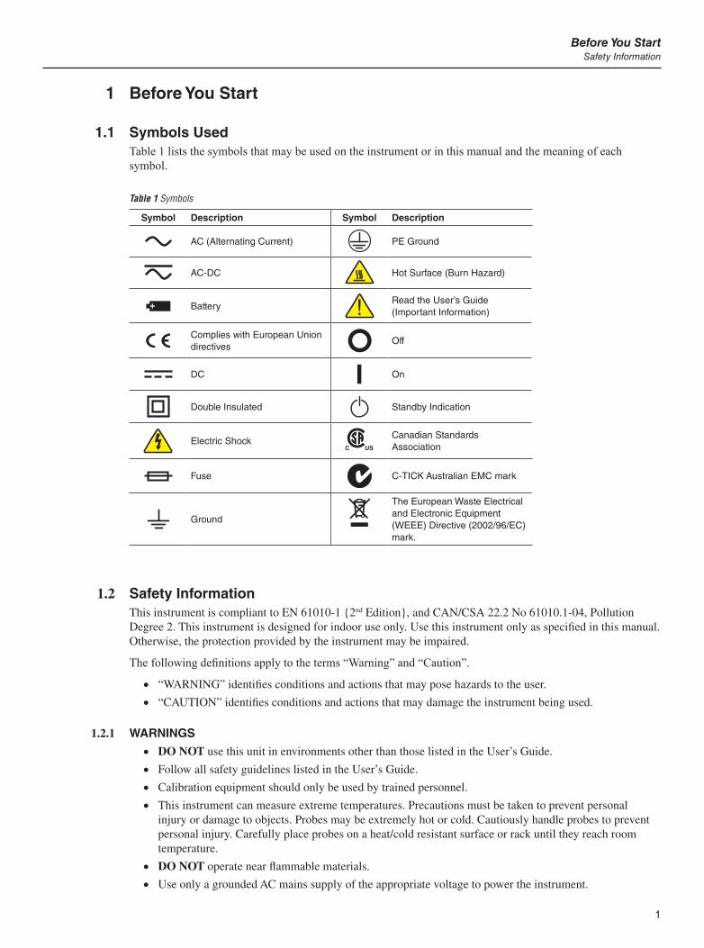
1.1 Symbols UsedTable 1 lists the symbols that may be used on the instrument or in this manual and the meaning of each symbol.
Table 1 Symbols
Symbol Description Symbol Description
AC (Alternating Current) PE Ground
AC-DC Hot Surface (Burn Hazard)
BatteryRead the User’s Guide (Important Information)
Complies with European Union directives
Off
DC On
Double Insulated Standby Indication
Electric ShockCanadian Standards Association
Fuse C-TICK Australian EMC mark
Ground
The European Waste Electrical and Electronic Equipment (WEEE) Directive (2002/96/EC) mark.
1.2 Safety InformationThis instrument is compliant to EN 61010-1 2nd Edition, and CAN/CSA 22.2 No 61010.1-04, Pollution Degree 2. This instrument is designed for indoor use only. Use this instrument only as specified in this manual. Otherwise, the protection provided by the instrument may be impaired.
The following definitions apply to the terms “Warning” and “Caution”.
“WARNING” identifies conditions and actions that may pose hazards to the user.
“CAUTION” identifies conditions and actions that may damage the instrument being used.
1.2.1 WARNINGS DO NOT use this unit in environments other than those listed in the User’s Guide.
Follow all safety guidelines listed in the User’s Guide.
Calibration equipment should only be used by trained personnel.
This instrument can measure extreme temperatures. Precautions must be taken to prevent personal injury or damage to objects. Probes may be extremely hot or cold. Cautiously handle probes to prevent personal injury. Carefully place probes on a heat/cold resistant surface or rack until they reach room temperature.
DO NOT operate near flammable materials.
Use only a grounded AC mains supply of the appropriate voltage to power the instrument.
1594A/1595A Super-ThermometerAuthorized Service Centers
2
DO NOT connect an AC mains supply that does not match the voltage setting on the back of the unit.
DO NOT use this instrument in combination with any probe ( PRT or thermistor) to measure the temperature or resistance of any device where the probe might come in contact with a conductor that is electrically energized. Severe electric shock, personal injury, or death may occur.
DO NOT position this instrument in a manner where it is difficult to reach the power cord or power entry module mains switch. When rack mounting the instrument, ensure the rack power cord and mains supply switch are accessible.
1.2.2 CAUTIONS If the instrument is dropped, struck, or handled in a way that causes internal or external physical
damage, immediately unplug the instrument, discontinue use, and contact a Fluke Authorized Service Center for repair. Do not attempt to disassemble or repair the instrument. Refer repairs or replacement of components to a Fluke Authorized Service Center.
DO NOT connect AC voltage to any input terminal on the instrument. Permanent damage to the instrument will result.
1.3 Authorized Service CentersPlease contact one of the following authorized Service Centers to coordinate service on your Fluke product:
Fluke Corporation
799 E. Utah Valley Drive
American Fork, UT 84003-9775
USA
Phone: +1.801.763.1600
Telefax: +1.801.763.1010
E-mail: [email protected]
Fluke Nederland B.V.
Customer Support Services
Science Park Eindhoven 5108
5692 EC Son
NETHERLANDS
Phone: +31-402-675300
Telefax: +31-402-675321
E-mail: [email protected]
Fluke Int’l Corporation
Service Center - Instrimpex
Room 2301 Sciteck Tower
22 Jianguomenwai Dajie
Chao Yang District
Beijing 100004, PRC
CHINA
Phone: +86-10-6-512-3436
Telefax: +86-10-6-512-3437
E-mail: [email protected]
3
Before You StartAuthorized Service Centers
Fluke South East Asia Pte Ltd.
Fluke ASEAN Regional Office
Service Center
60 Alexandra Terrace #03-16
The Comtech (Lobby D)
118502
SINGAPORE
Phone: +65 6799-5588
Telefax: +65 6799-5588
E-mail: [email protected]
When contacting these Service Centers for support, please have the following information available:
Model Number
Serial Number
Voltage
Complete description of the problem

5
Introduction and SpecificationsSpecifications
2 Introduction and Specifications
2.1 IntroductionThe Fluke family of Hart Super-Thermometers long ago established the standard for easy-to-use, precision temperature measurement instrumentation. Laboratories worldwide have selected the Super-Thermometer not only for the assurance of achieving high-quality results, but also for the innovative features that increase productivity in the lab. The Fluke 1594A and 1595A Hart Super-Thermometers continue this legacy adding new patent pending measurement technology and features that truly are best in class. Below is a summary of key capabilities and features.
Typical 1595A accuracy 0.2 ppm (0.05 mK), 1594A accuracy 0.8 ppm (0.2 mK) Sample rates as fast as 1 second Measures SPRTs, HTPRTs, PRTs, and thermistors Four input channels on the front panel accept most probe terminations with the patented DWF, gold-
plated, tellurium-copper, quick-connect terminals Configurable standby current for each input channel minimizes self-heating transients when scanning
between channels Two input channels on the back panel, dedicated for external standard resistors, keep the front panel
inputs free for Reference Thermometers or Standard Resistors and UUTs Channel Select Keys above each input channel change color to indicate whether a channel is actively
measuring, in standby, or inactive—pressing a channel key activates the selected channel Temperature-controlled internal reference resistors allow for traceable temperature and absolute
resistance measurements in ambient conditions from 15 °C to 30 °C Patent pending, Ratio Self-Calibration performs a linearity check or calibration of the Super-
Thermometer ratio accuracy without the need of any external equipment Automated Zero-Power Measurement allows for determination and/or cancellation of a thermometer’s
self-heating error Updated computer interface with USB control, RS-232, and IEEE-488 included as standard Ethernet connection allows for remote view of the Super-Thermometer’s display from a web browser USB memory device on the front panel to accommodate data logging, transfer of probe parameters, and
storage and retrieval of Super-Thermometer user configurations VGA output allows the Super-Thermometer’s screen to be displayed on a VGA monitor Selectable operating language: English, Chinese, Japanese, Spanish, French, German, or Russian Intuitive User Interface makes the Super-Thermometer easy to configure and use right out of the box
2.2 Specifications
2.2.1 General
Current best practices in metrology require uncertainty analyses to be in compliance with the ISO Guide to the Expression of Uncertainty in Measurement (often referred to as the “GUM”). For convenience, the specifica-tions in this section are listed in k = 2 (95%) coverage and in k = 3 (99%) coverage to allow the user to easily apply the specifications in an uncertainty analysis.
The following specifications apply after the standard warm-up period of 30 minutes. The Super-Thermometer is designed to measure with accuracy and stability without the need for internal auto-cal or zeroing routines. To realize the full potential of measurement ability, accepted metrology practices such as the use of proper wiring should be adhered to. In addition, it is important to ensure that the instrument is correctly set up.
The specifications are divided into three categories: primary specifications, ancillary specifications, and gen-eral specifications.
1594A/1595A Super-ThermometerSpecifications
6
Primary Specifications: the core set of measurement accuracy specifications of the Super-Thermometer. They are guaranteed for performance verification at the 99% confidence level.
Ancillary Specifications: additional specifications that help the user understand more of the uncertainties involved in measurement. Since they may be subject to the application and setting in which the Super-Ther-mometer is used, they are not guaranteed for performance verification but should be considered typical.
General specifications: general specifications such as measurement range, environmental operating range, dimensions, etc.
2.2.2 Primary Specifications
2.2.2.1 Resistance Ratio Accuracy
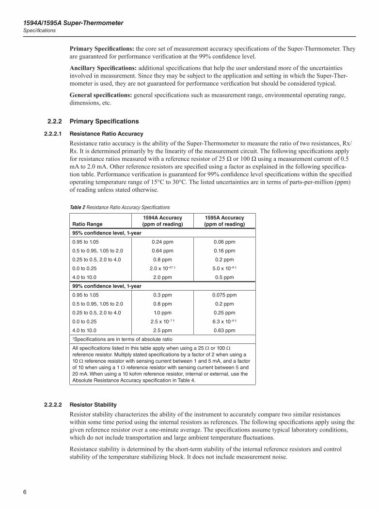
Resistance ratio accuracy is the ability of the Super-Thermometer to measure the ratio of two resistances, Rx/Rs. It is determined primarily by the linearity of the measurement circuit. The following specifications apply for resistance ratios measured with a reference resistor of 25 Ω or 100 Ω using a measurement current of 0.5 mA to 2.0 mA. Other reference resistors are specified using a factor as explained in the following specifica-tion table. Performance verification is guaranteed for 99% confidence level specifications within the specified operating temperature range of 15°C to 30°C. The listed uncertainties are in terms of parts-per-million (ppm) of reading unless stated otherwise.
Table 2 Resistance Ratio Accuracy Specifications
Ratio Range1594A Accuracy (ppm of reading)
1595A Accuracy (ppm of reading)
95% confidence level, 1-year
0.95 to 1.05 0.24 ppm 0.06 ppm
0.5 to 0.95, 1.05 to 2.0 0.64 ppm 0.16 ppm
0.25 to 0.5, 2.0 to 4.0 0.8 ppm 0.2 ppm
0.0 to 0.25 2.0 x 10–07 † 5.0 x 10⁻⁸ †
4.0 to 10.0 2.0 ppm 0.5 ppm
99% confidence level, 1-year
0.95 to 1.05 0.3 ppm 0.075 ppm
0.5 to 0.95, 1.05 to 2.0 0.8 ppm 0.2 ppm
0.25 to 0.5, 2.0 to 4.0 1.0 ppm 0.25 ppm
0.0 to 0.25 2.5 x 10⁻⁷ † 6.3 x 10⁻⁸ †
4.0 to 10.0 2.5 ppm 0.63 ppm†Specifications are in terms of absolute ratio
All specifications listed in this table apply when using a 25 W or 100 W reference resistor. Multiply stated specifications by a factor of 2 when using a 10 W reference resistor with sensing current between 1 and 5 mA, and a factor of 10 when using a 1 W reference resistor with sensing current between 5 and 20 mA. When using a 10 kohm reference resistor, internal or external, use the Absolute Resistance Accuracy specification in Table 4.
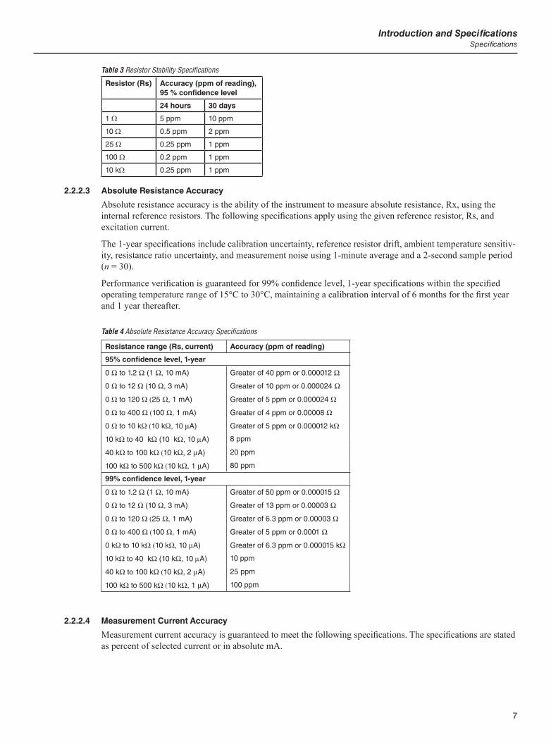
2.2.2.2 Resistor Stability
Resistor stability characterizes the ability of the instrument to accurately compare two similar resistances within some time period using the internal resistors as references. The following specifications apply using the given reference resistor over a one-minute average. The specifications assume typical laboratory conditions, which do not include transportation and large ambient temperature fluctuations.
Resistance stability is determined by the short-term stability of the internal reference resistors and control stability of the temperature stabilizing block. It does not include measurement noise.
7
Introduction and SpecificationsSpecifications
Table 3 Resistor Stability Specifications
Resistor (Rs) Accuracy (ppm of reading), 95 % confidence level
24 hours 30 days
1 W 5 ppm 10 ppm
10 W 0.5 ppm 2 ppm
25 W 0.25 ppm 1 ppm
100 W 0.2 ppm 1 ppm
10 kW 0.25 ppm 1 ppm
2.2.2.3 Absolute Resistance Accuracy
Absolute resistance accuracy is the ability of the instrument to measure absolute resistance, Rx, using the internal reference resistors. The following specifications apply using the given reference resistor, Rs, and excitation current.
The 1-year specifications include calibration uncertainty, reference resistor drift, ambient temperature sensitiv-ity, resistance ratio uncertainty, and measurement noise using 1-minute average and a 2-second sample period (n = 30).
Performance verification is guaranteed for 99% confidence level, 1-year specifications within the specified operating temperature range of 15°C to 30°C, maintaining a calibration interval of 6 months for the first year and 1 year thereafter.
Table 4 Absolute Resistance Accuracy Specifications
Resistance range (Rs, current) Accuracy (ppm of reading)
95% confidence level, 1-year
0 W to 1.2 W (1 W, 10 mA) Greater of 40 ppm or 0.000012 W
0 W to 12 W (10 W, 3 mA) Greater of 10 ppm or 0.000024 W
0 W to 120 W (25 W, 1 mA) Greater of 5 ppm or 0.000024 W
0 W to 400 W (100 W, 1 mA) Greater of 4 ppm or 0.00008 W
0 W to 10 kW (10 kW, 10 mA) Greater of 5 ppm or 0.000012 kW
10 kW to 40 kW (10 kW, 10 mA) 8 ppm
40 kW to 100 kW (10 kW, 2 mA) 20 ppm
100 kW to 500 kW (10 kW, 1 mA) 80 ppm
99% confidence level, 1-year
0 W to 1.2 W (1 W, 10 mA) Greater of 50 ppm or 0.000015 W
0 W to 12 W (10 W, 3 mA) Greater of 13 ppm or 0.00003 W
0 W to 120 W (25 W, 1 mA) Greater of 6.3 ppm or 0.00003 W
0 W to 400 W (100 W, 1 mA) Greater of 5 ppm or 0.0001 W
0 kW to 10 kW (10 kW, 10 mA) Greater of 6.3 ppm or 0.000015 kW
10 kW to 40 kW (10 kW, 10 mA) 10 ppm
40 kW to 100 kW (10 kW, 2 mA) 25 ppm
100 kW to 500 kW (10 kW, 1 mA) 100 ppm
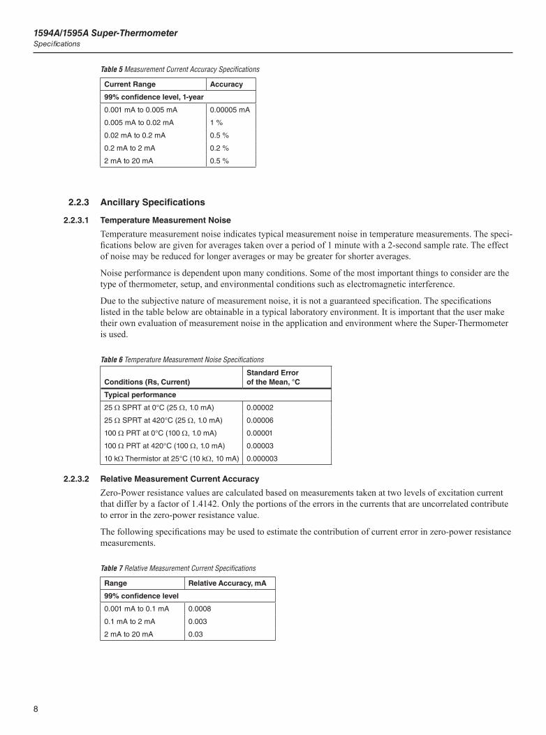
2.2.2.4 Measurement Current Accuracy
Measurement current accuracy is guaranteed to meet the following specifications. The specifications are stated as percent of selected current or in absolute mA.
1594A/1595A Super-ThermometerSpecifications
8
Table 5 Measurement Current Accuracy Specifications
Current Range Accuracy
99% confidence level, 1-year
0.001 mA to 0.005 mA 0.00005 mA
0.005 mA to 0.02 mA 1 %
0.02 mA to 0.2 mA 0.5 %
0.2 mA to 2 mA 0.2 %
2 mA to 20 mA 0.5 %
2.2.3 Ancillary Specifications
2.2.3.1 Temperature Measurement Noise
Temperature measurement noise indicates typical measurement noise in temperature measurements. The speci-fications below are given for averages taken over a period of 1 minute with a 2-second sample rate. The effect of noise may be reduced for longer averages or may be greater for shorter averages.
Noise performance is dependent upon many conditions. Some of the most important things to consider are the type of thermometer, setup, and environmental conditions such as electromagnetic interference.
Due to the subjective nature of measurement noise, it is not a guaranteed specification. The specifications listed in the table below are obtainable in a typical laboratory environment. It is important that the user make their own evaluation of measurement noise in the application and environment where the Super-Thermometer is used.
Table 6 Temperature Measurement Noise Specifications
Conditions (Rs, Current)Standard Error of the Mean, °C
Typical performance
25 W SPRT at 0°C (25 W, 1.0 mA) 0.00002
25 W SPRT at 420°C (25 W, 1.0 mA) 0.00006
100 W PRT at 0°C (100 W, 1.0 mA) 0.00001
100 W PRT at 420°C (100 W, 1.0 mA) 0.00003
10 kW Thermistor at 25°C (10 kW, 10 mA) 0.000003
2.2.3.2 Relative Measurement Current Accuracy
Zero-Power resistance values are calculated based on measurements taken at two levels of excitation current that differ by a factor of 1.4142. Only the portions of the errors in the currents that are uncorrelated contribute to error in the zero-power resistance value.
The following specifications may be used to estimate the contribution of current error in zero-power resistance measurements.
Table 7 Relative Measurement Current Specifications
Range Relative Accuracy, mA
99% confidence level
0.001 mA to 0.1 mA 0.0008
0.1 mA to 2 mA 0.003
2 mA to 20 mA 0.03
9
Introduction and SpecificationsSpecifications
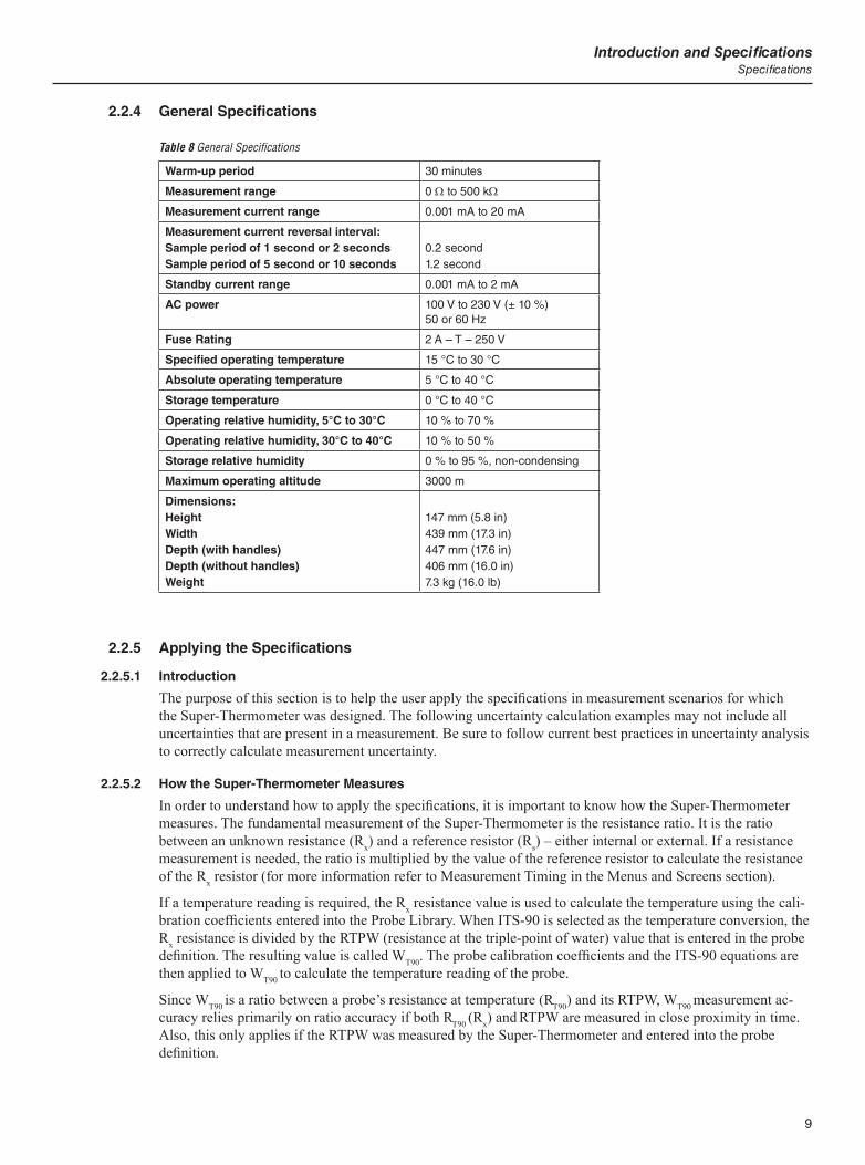
2.2.4 General Specifications
Table 8 General Specifications
Warm-up period 30 minutes
Measurement range 0 W to 500 kW
Measurement current range 0.001 mA to 20 mA
Measurement current reversal interval:Sample period of 1 second or 2 secondsSample period of 5 second or 10 seconds
0.2 second1.2 second
Standby current range 0.001 mA to 2 mA
AC power 100 V to 230 V (± 10 %) 50 or 60 Hz
Fuse Rating 2 A – T – 250 V
Specified operating temperature 15 °C to 30 °C
Absolute operating temperature 5 °C to 40 °C
Storage temperature 0 °C to 40 °C
Operating relative humidity, 5°C to 30°C 10 % to 70 %
Operating relative humidity, 30°C to 40°C 10 % to 50 %
Storage relative humidity 0 % to 95 %, non-condensing
Maximum operating altitude 3000 m
Dimensions:HeightWidthDepth (with handles)Depth (without handles)Weight
147 mm (5.8 in)439 mm (17.3 in)447 mm (17.6 in)406 mm (16.0 in)7.3 kg (16.0 lb)
2.2.5 Applying the Specifications
2.2.5.1 Introduction
The purpose of this section is to help the user apply the specifications in measurement scenarios for which the Super-Thermometer was designed. The following uncertainty calculation examples may not include all uncertainties that are present in a measurement. Be sure to follow current best practices in uncertainty analysis to correctly calculate measurement uncertainty.
2.2.5.2 How the Super-Thermometer Measures
In order to understand how to apply the specifications, it is important to know how the Super-Thermometer measures. The fundamental measurement of the Super-Thermometer is the resistance ratio. It is the ratio between an unknown resistance (Rx) and a reference resistor (Rs) – either internal or external. If a resistance measurement is needed, the ratio is multiplied by the value of the reference resistor to calculate the resistance of the Rx resistor (for more information refer to Measurement Timing in the Menus and Screens section).
If a temperature reading is required, the Rx resistance value is used to calculate the temperature using the cali-bration coefficients entered into the Probe Library. When ITS-90 is selected as the temperature conversion, the Rx resistance is divided by the RTPW (resistance at the triple-point of water) value that is entered in the probe definition. The resulting value is called WT90. The probe calibration coefficients and the ITS-90 equations are then applied to WT90 to calculate the temperature reading of the probe.
Since WT90 is a ratio between a probe’s resistance at temperature (RT90) and its RTPW, WT90 measurement ac-curacy relies primarily on ratio accuracy if both RT90 (Rx) and RTPW are measured in close proximity in time. Also, this only applies if the RTPW was measured by the Super-Thermometer and entered into the probe definition.

1594A/1595A Super-ThermometerSpecifications
10
When calibrating an SPRT on the ITS-90, the WT90 value is measured at required fixed-point temperatures. This is done by measuring the resistance of the SPRT at a fixed-point temperature followed immediately by measurement of the RTPW. This is repeated for each temperature point. Once again the ratio accuracy of the Super-Thermometer, applied to each measured resistance, determines the accuracy of the resulting WT90value.
2.2.5.3 Example 1: Measuring an SPRT
This section explains how to calculate the uncertainty of a temperature measurement when measuring a calibrated 25.5 W SPRT at 157 °C, using the internal 25 W reference resistor in a 1595A. Since the Super-Thermometer measurement accuracy is directly related to other sources of uncertainty, additional uncertainties will be included in the calculation for completeness.
Since an SPRT can be measured with different techniques, two different calculations will be presented to rep-resent the most common and recommended techniques.
2.2.5.3.1 Measuring With Updated RTPW
In this example, the RTPW of the SPRT is measured by a 1595A and entered into the SPRT’s probe definition in the 1595A. Then the SPRT is measured at 157 °C, in temperature mode, using the coefficients entered in the SPRT probe definition.
As explained above, this measurement technique primarily uses the ratio accuracy of the Super-Thermometer. It is equivalent to measuring the ITS-90 WT90 value and using it to calculate temperature.
The total uncertainty of this measurement is based on six uncorrelated uncertainties. These uncertainties are:
Resistance ratio accuracy of the 1595A at 157 °C Measurement noise at 157 °C Resistance ratio accuracy of the 1595A at 0.01 °C (triple-point of water) Measurement noise at 0.01 °C Reference resistor drift Uncertainty of the triple-point of water cell
The following demonstrate how to calculate and combine the listed uncertainties.
2.2.5.3.2 Resistance Ratio Accuracy at 157 °C
The resistance of the SPRT, when measuring at 157 °C, is 41.1 Ω. The ratio of this resistance against the 25 W reference resistor is 1.644. From the resistance ratio accuracy specifications of the 1595A, the standard uncertainty (k = 1) when measuring a resistance ratio of 1.644 is 0.08 ppm. This is converted to temperature by dividing 0.08 ppm by 1.0 × 106 and then multiplying by 1.644. The result is then divided by WT90 sensitiv-ity (dW/dT) at 157 °C which is 0.0038 (found on the SPRT calibration report, see tip below). The final result is 0.000035 °C.
2.2.5.3.3 Measurement Noise at 157 °C
Random error due to measurement noise must be included as an uncertainty. During measurement at 157 °C, it is observed that the standard error of the mean is 0.000040 °C.
Note: The user must monitor measurement noise and use the actual measured measurement noise in the uncertainty calculations.
2.2.5.3.4 Resistance Ratio Accuracy at 0.01 °C
Uncertainties related to measuring the RTPW of the SPRT must be included in the analysis. However, RTPW uncertainties are magnified when applied to uncertainties of temperatures that are above 0 °C. At 157 °C this magnification is estimated by multiplying RTPW uncertainties by the WT90 value at 157 °C (1.612 in this example).
The resistance of the SPRT at the triple-point of water is approximately 25.5 Ω. The resistance ratio against the 25 W reference resistor is then about 1.02. From the resistance ratio accuracy specifications of the 1595A, the standard uncertainty due to linearity while measuring a resistance ratio of 1.02 is 0.03 ppm. This specification
11
Introduction and SpecificationsSpecifications
is converted to temperature by dividing 0.03 ppm by 1.0 × 106 and then multiplying by 1.02. The result is then divided by WT90 sensitivity, dW/dT, at 0.01 °C, which is 0.004. The final result is 0.000008 °C. After multiply-ing by WT90 (1.612), the uncertainty of the RTPW resistance ratio, when applied to 157 °C, is 0.000013 °C.
2.2.5.3.5 Measurement Noise at 0.01 °C
During measurement of the RTPW, it is observed that the standard error of the mean is 0.0000018 Ω. To convert this value into temperature, divide by the resistance sensitivity (dR/dT) of the SPRT at 0.01 °C. dR/dT at 0.01 °C is 0.1 W/°C (see tip below). The result is 0.000018 °C. Multiplying by WT90 (1.612) yields 0.000029 °C.
Tip: Most SPRT calibration reports list the Temperature versus W values of the SPRT in a table. Typically, the dT/dW value at each temperature will be included in the same table. dR/dT can be calculated by inverting dT/dW and multiplying by the RTPW of the SPRT. Also, dW/dT can be calculated by simply inverting dT/dW.
2.2.5.3.6 Uncertainty of the TPW Cell
Uncertainty of the temperature of the triple-point of water cell must also be included. For this example, the standard uncertainty of the triple-point of water cell is 0.000050 °C. Multiplying by WT90 (1.612) results in 0.000081 °C.
2.2.5.3.7 Reference Resistor Drift
Possible drift of the 25 W reference resistor between the TPW measurement and the 157 °C measurement must be accounted for. To reduce the possible error, both measurements should be taken in close proximity in time. For this example, the 24-hour stability specification will be used. This requires that both measurements are taken within the same 24-hour period. The standard uncertainty due to drift of the reference resistor is 0.125 ppm. This is converted to temperature by dividing 0.125 ppm by 1.0 × 106 and then multiplying by 1.612. The result is then divided by WT90 sensitivity (dW/dT) at 157 °C which is 0.0038. The result is 0.000053 °C.
2.2.5.3.8 Combining the Uncertainties
At this point, all of the uncertainties can be combined by root-sum-square (RSS) since they are uncorrelated. Even though the 1595A resistance ratio accuracy is used twice in the calculation, both measurements are con-sidered uncorrelated.
This RSS sum produces a combined standard uncertainty of 0.000115 °C. Multiplying by the coverage factor (k = 2) results in a total expanded uncertainty of 0.000230 °C.
In this example, it is assumed the SPRT did not drift between the measurements at the TPW and 157 °C. It may be necessary to add an additional uncertainty that accounts for SPRT drift.
2.2.5.3.9 Measuring With Calibration Report RTPW
In this example, the SPRT is monitored by periodically measuring its RTPW in a TPW cell but the original RTPW from the SPRT calibration report is entered in the 1595A, not the measured RTPW. This requires a dif-ferent set of specifications to be used in the measurement uncertainty.
The uncertainty of this measurement is based on four uncorrelated uncertainties. These uncertainties are:
Resistance accuracy of the 1595A when measuring the SPRT at 157 °C Measurement noise at 157 °C Uncertainty of the SPRT resistance at the triple-point of water Drift of the RTPW of the SPRT
2.2.5.3.10 Resistance Accuracy at 157 °C
The resistance of the SPRT at 157 °C is 41.1 Ω. Using the 25 Ω internal reference resistor, the 1595A one-year resistance standard uncertainty is 2.5 ppm. This uncertainty, in terms of temperature, is calculated by first dividing 2.5 ppm by 1.0 × 106 then multiplying by 41.1 Ω. The result is then divided by the sensitivity (dR/dT)
1594A/1595A Super-ThermometerSpecifications
12
of the SPRT at 157 °C which is 0.1 Ω/°C (see tip above). This results in a standard temperature uncertainty of 0.001028 °C.
2.2.5.3.11 Measurement Noise at 157 °C
During measurement at 157 °C, the standard error of the mean (as reported by the 1595A) is observed to be 0.00004 °C.
Note: The user must monitor measurement noise and use the actual measured measurement noise in the uncer-tainty calculations.
2.2.5.3.12 Uncertainty of the Calibration Report RTPW
In this example, the RTPW is not measured and entered into the 1595A. The RTPW from the SPRT calibration report is entered into the 1595A. The standard (k = 1) uncertainty of the RTPW value listed on the calibration report must be included. In this example, it is 0.0001 °C. As explained in the previous example, all uncertain-ties related to RTPW must be multiplied by WT90 of the measured temperature. Multiplying by 1.612 yields 0.000161 °C.
2.2.5.3.13 Drift of the RTPW of the SPRT
Since an SPRT tends to drift, the long-term drift should be included as a source of uncertainty. In this example the SPRT is allowed to drift 0.002 °C. The assumed distribution of this uncertainty is rectangular. To convert to a standard uncertainty divide by 1.732 (square root of 3). The result, 0.001155 °C, multiplied by 1.612 yields a standard uncertainty of 0.001861 °C.
2.2.5.3.14 Combining the Uncertainties
At this point, all of the uncertainties can be combined by root-sum-square (RSS) since they are uncorrelated. The RSS sum produces a combined standard uncertainty of 0.002133 °C. Multiplying by the coverage factor (k = 2), and rounding, results in a total expanded uncertainty of 0.0043 °C.
2.2.5.4 Example 2: Calibrating an SPRT
As explained in “How the Super-Thermometer Measures” at the beginning of this section, the calibration of an SPRT is performed by measuring the resistance at some required fixed-point temperature and then at the triple-point of water. The two measurements are combined by division to get a WT90 value. The uncertainty of WT90 is based primarily on the ratio accuracy of the Super-Thermometer.
In this example, an SPRT is calibrated at 419.527 °C (FP of Zinc). The RTPW is measured directly afterward. The uncertainties resulting from the 1595A in this example are:
Resistance ratio accuracy of the 1595A at 419.527 °C Measurement noise at 419.527 °C Resistance ratio accuracy of the 1595A at 0.01°C (triple-point of water) Measurement noise at 0.01°C Reference resistor drift
The uncertainties in this example are calculated and combined as described in Example 1. However, there is a slight difference in the reference resistor drift component.
2.2.5.4.1 Reference Resistor Drift
In Example 1, the 24-hour stability specification of the internal 25 Ω is used. This may not be necessary when calibrating an SPRT. When calibrating an SPRT typically both measurements of WT90 are taken in close prox-imity of time (< 8 hours elapsed time). It is possible for the reference resistor drift to be negligible, especially if the Super-Thermometer is in a stable temperature environment.
To be sure reference resistor drift is correctly estimated, the user should perform a test to determine actual reference resistor drift over the elapsed time. One way to perform this test is to measure a very stable exter-nal reference resistor over the actual time period using the internal reference resistor. If it is not possible to measure the reference resistor drift, it may be necessary to use the 24-hour stability specification resulting in a slightly larger total uncertainty. Another alternative is to use an external reference resistor of very low drift.

13
Introduction and SpecificationsSpecifications
2.2.5.4.2 Example 3: Measuring Zero-Power Resistance
The purpose of this example is to demonstrate how the Relative Current specification applies when performing a zero-power measurement. The zero-power uncertainty calculated in this example would be added to the rest of the uncertainties involved in the measurement as explained in previous examples. The intention of the zero-power measurement is to remove measurement errors due to self-heating of the SPRT.
In this example a 1595A is used to measure a 25 Ω SPRT at the triple-point of water using the Zero-Power function. The SPRT is measured at nominal current, 1.0 mA and 1.4142 mA (double-power current). In this example, the self-heating sensitivity of the SPRT in a triple-point of water cell is 0.0024 °C/mA. This was found by using the Zero-Power function and reading the SELF-HEATING field in the Zero-Power results screen. This value will vary significantly depending on temperature, measurement medium, and probe construction.
The uncertainties used to calculate zero-power uncertainty are:
Ratio accuracy of the 1595A Measurement noise Relative current accuracy of the 1595A Reference resistor stability
2.2.5.4.3 Resistance Ratio Accuracy at 0.01 °C
The ratio accuracy at 0.01 °C is based on using the internal 25 Ω resistor to measure a resistance of 25.5 Ω. The 1595A standard uncertainty of resistance ratio is 0.03 ppm. To convert this value to temperature divide by 1.0 × 10⁶ and multiply by 1.02 (Rx/Rs). The result is then divided by 0.004 (WT90 sensitivity, dW/dT, at 0.01 °C, see above). The final result is 0.000008 °C.
2.2.5.4.4 Measurement Noise
The Zero-Power function reports the standard error of the mean of the zero-power value in the STANDARD ERROR field. In this example, the standard error of the mean is 0.0000018 Ω. To convert this value into tem-perature, divide by the resistance sensitivity (dR/dT) of the SPRT at 0.01 °C. dR/dT at 0.01 °C is 0.1 W/°C (see tip above). The result is 0.000018 °C.
2.2.5.4.5 Relative Current Accuracy
The relative measurement current specifications are listed in Table 7 of the Specifications section. The stan-dard uncertainty of the measurement current over the range 1.0 mA to 1.4142 mA is 0.0015 mA. This is converted to temperature by multiplying by the SPRT self-heating sensitivity at 0.01 °C which is 0.0024 °C/mA. The result is 0.0000036 °C.
2.2.5.4.6 Reference Resistor Stability
Since the individual measurements of the zero-power measurement are taken in close proximity in time, the drift of the reference resistor is considered negligible.
2.2.5.4.7 Combining the Uncertainties
The uncertainties of the zero-power measurement are combined by RSS with the rest of the uncertainties involved in the measurement. See the previous examples for the other uncertainties.
2.2.5.5 Example 4: Measuring a 100 Ω PRT
In this example the temperature of a typical 100 Ω PRT is measured at 420 °C with a 1595A. The uncertainties in the measurement associated with the 1595A are as follows:
Resistance accuracy of the 1595A Measurement noise at 420 °C
2.2.5.5.1 Resistance Accuracy at 420 °C
First, calculate the 1595A absolute resistance accuracy at 257 Ω (the resistance of the 100 Ω PRT at 420 °C). The one-year absolute resistance standard uncertainty (k = 1) of the 1594A, using the internal 100 Ω resistor, is 2.0 ppm. To convert this to an uncertainty in temperature, multiply 2.0 ppm by 1.0 × 106 then multiply by
1594A/1595A Super-ThermometerSpecifications
14
257 Ω. Divide the result by the sensitivity of the PRT (dR/dT) at 420 °C. This can be found in the PRT calibra-tion report. For this example, 0.4 Ω/°C is used. The resulting uncertainty is 0.0013°C.
2.2.5.5.2 Measurement Noise at 420 °C
The noise of the measurement at 420 °C is observed using the Standard Error of the Mean statistic field of the 1595A. In this example it is 0.00003 °C.
2.2.5.5.3 Combining the Uncertainties
To calculate the entire uncertainty of the measurement, the standard uncertainties from the 1595A should be combined with the (k = 1) PRT calibration uncertainty at 420 °C. The standard uncertainties are combined by RSS and then multiplied by the required coverage factor.
2.2.5.6 Example 5: Measuring a 10 kΩ Thermistor
In this example, a 1595A is used to measure a 10 kΩ thermistor probe at 0 °C. The 1595A accuracy, when measuring the thermistor probe is based on the following:
Resistance accuracy of the 1595A Measurement noise
2.2.5.6.1 Resistance Accuracy
First, calculate the 1595A absolute resistance accuracy at 26839.94 (the resistance of the 10-k Ω thermistor probe at 0 °C) when using the 10 k Ω internal reference resistor. The one-year absolute resistance accuracy is 4 ppm of reading (k = 1). This is converted to temperature by dividing 4 ppm by 1.0 × 106 and multiplying by 26839.94 Ω. The result is then divided by dR/dt of the thermistor probe at 0 °C which, in this example, is 1244.9 Ω/°C. The final result is 0.000085 °C.
2.2.5.6.2 Measurement Noise
Measurement noise is best observed by using the Standard Error of the Mean statistics field of the Super-Ther-mometer. In this example, the standard error of the mean is 0.000004 °C.
2.2.5.6.3 Combining the Uncertainties
If the thermistor probe is being measured in temperature mode with calibration coefficients, the standard uncertainty of the calibration (listed on the calibration report) would be combined by RSS with the resistance accuracy and measurement noise uncertainties.
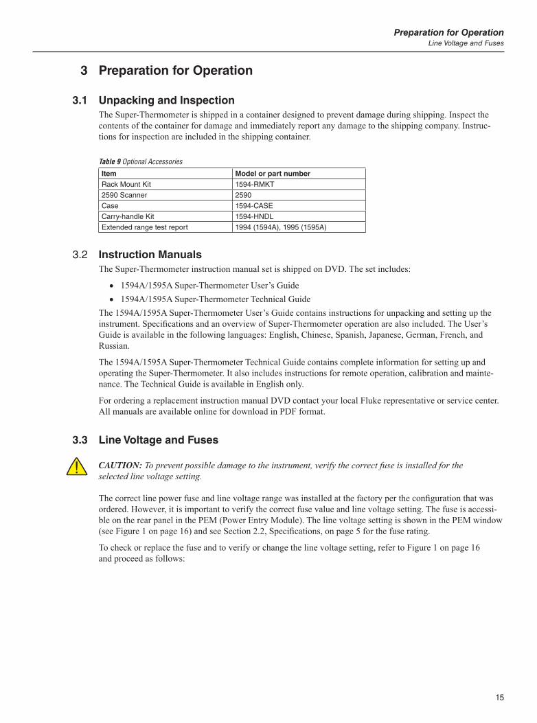
15
Preparation for OperationLine Voltage and Fuses
3 Preparation for Operation
3.1 Unpacking and InspectionThe Super-Thermometer is shipped in a container designed to prevent damage during shipping. Inspect the contents of the container for damage and immediately report any damage to the shipping company. Instruc-tions for inspection are included in the shipping container.
Table 9 Optional Accessories
Item Model or part numberRack Mount Kit 1594-RMKT
2590 Scanner 2590
Case 1594-CASE
Carry-handle Kit 1594-HNDL
Extended range test report 1994 (1594A), 1995 (1595A)
3.2 Instruction ManualsThe Super-Thermometer instruction manual set is shipped on DVD. The set includes:
1594A/1595A Super-Thermometer User’s Guide 1594A/1595A Super-Thermometer Technical Guide
The 1594A/1595A Super-Thermometer User’s Guide contains instructions for unpacking and setting up the instrument. Specifications and an overview of Super-Thermometer operation are also included. The User’s Guide is available in the following languages: English, Chinese, Spanish, Japanese, German, French, and Russian.
The 1594A/1595A Super-Thermometer Technical Guide contains complete information for setting up and operating the Super-Thermometer. It also includes instructions for remote operation, calibration and mainte-nance. The Technical Guide is available in English only.
For ordering a replacement instruction manual DVD contact your local Fluke representative or service center. All manuals are available online for download in PDF format.
3.3 Line Voltage and Fuses
CAUTION: To prevent possible damage to the instrument, verify the correct fuse is installed for the selected line voltage setting.
The correct line power fuse and line voltage range was installed at the factory per the configuration that was ordered. However, it is important to verify the correct fuse value and line voltage setting. The fuse is accessi-ble on the rear panel in the PEM (Power Entry Module). The line voltage setting is shown in the PEM window (see Figure 1 on page 16) and see Section 2.2, Specifications, on page 5 for the fuse rating.
To check or replace the fuse and to verify or change the line voltage setting, refer to Figure 1 on page 16 and proceed as follows:

1594A/1595A Super-ThermometerConnecting to Line Power
16
1. Disconnect line power.
2. Observe what line voltage setting is displayed in the PEM window. If it is correct, the fuse assembly will be re-inserted in the same orientation it is removed. Otherwise, it will need to be rotated 180° before re-insertion.
3. Open the fuse compartment by inserting a screwdriver blade in the slot located at the top of the fuse compartment and open the PEM door.
4. Use the screwdriver blade to pry out the fuse block by inserting the blade in the slot located at the top of the fuse block.
5. Remove the fuses from the assembly for replacement or verification. Be sure the correct fuses are installed.
6. Reinstall the fuse assembly by pushing it back into the PEM while ensuring that the correct line voltage label is shown in the PEM window. Close the PEM door so it locks in place.
Figure 1 PEM (Power Entry Module)
3.4 Connecting to Line Power
WARNING: To avoid electrical shock, connect the factory supplied three-prong line power cord to a properly grounded power outlet. Do not use a two-prong adapter or extension cord that will break the ground connection.
After the line voltage setting and correct fuse are verified, connect the instrument to a properly grounded three-prong outlet using the provided line voltage cord.
3.5 Placement and Rack MountingIn general, place the Super-Thermometer in an area free of drafts and excessive electrical noise. Refer to the specifications for environmental requirements.
The Super-Thermometer is designed to be used on a bench-top or installed in a standard width rack with the optional rack mount kit. For bench-top use it is equipped with hinged, non-slip feet. For rack mount instruc-tions, refer to the rack mount kit instruction manual.
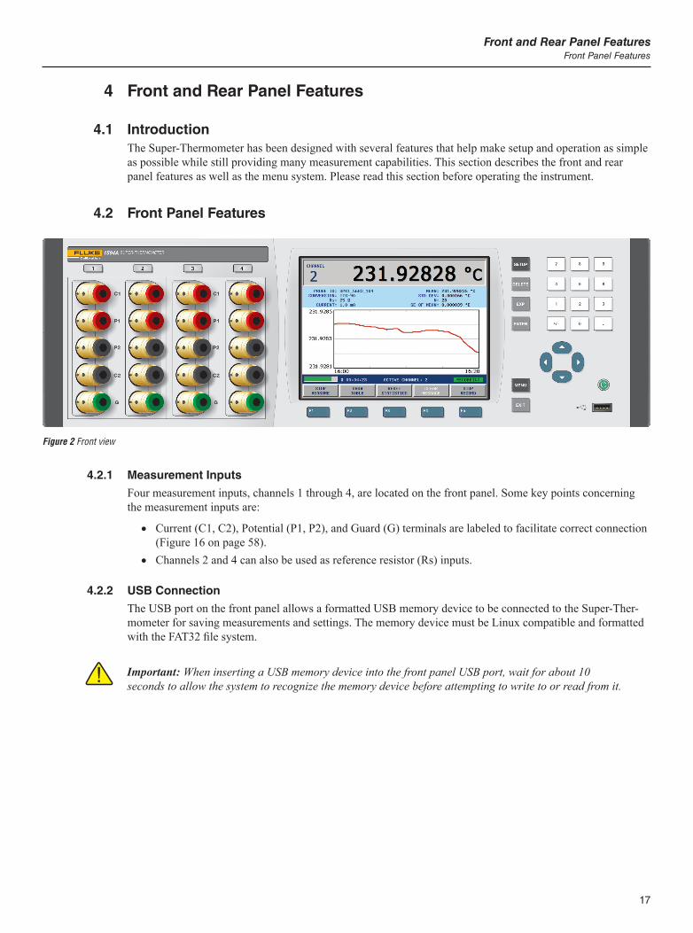
17
Front and Rear Panel FeaturesFront Panel Features
4 Front and Rear Panel Features
4.1 IntroductionThe Super-Thermometer has been designed with several features that help make setup and operation as simple as possible while still providing many measurement capabilities. This section describes the front and rear panel features as well as the menu system. Please read this section before operating the instrument.
4.2 Front Panel Features
Figure 2 Front view
4.2.1 Measurement Inputs
Four measurement inputs, channels 1 through 4, are located on the front panel. Some key points concerning the measurement inputs are:
Current (C1, C2), Potential (P1, P2), and Guard (G) terminals are labeled to facilitate correct connection (Figure 16 on page 58).
Channels 2 and 4 can also be used as reference resistor (Rs) inputs.
4.2.2 USB Connection
The USB port on the front panel allows a formatted USB memory device to be connected to the Super-Ther-mometer for saving measurements and settings. The memory device must be Linux compatible and formatted with the FAT32 file system.
Important: When inserting a USB memory device into the front panel USB port, wait for about 10 seconds to allow the system to recognize the memory device before attempting to write to or read from it.
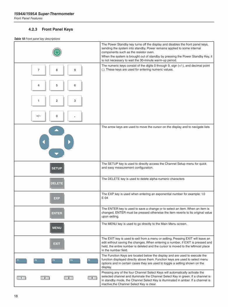
1594A/1595A Super-ThermometerFront Panel Features
18
4.2.3 Front Panel Keys
Table 10 Front panel key descriptions
The Power Standby key turns off the display and disables the front panel keys, sending the system into standby. Power remains applied to some internal components such as the resistor oven.When the system is brought out of standby by pressing the Power Standby Key, it is not necessary to wait the 30-minute warm-up period.
The numeric keys consist of the digits 0 through 9, sign (+/-), and decimal point (.). These keys are used for entering numeric values.
The arrow keys are used to move the cursor on the display and to navigate lists
The SETUP key is used to directly access the Channel Setup menu for quick and easy measurement configuration.
The DELETE key is used to delete alpha-numeric characters
The EXP key is used when entering an exponential number for example: 1.0 E-04
The ENTER key is used to save a change or to select an item. When an item is changed, ENTER must be pressed otherwise the item reverts to its original value upon exiting.
The MENU key is used to go directly to the Main Menu screen.
The EXIT key is used to exit from a menu or setting. Pressing EXIT will leave an edit without saving the changes. When entering a number, if EXIT is pressed and held, the entire number is deleted and the cursor is moved to the leftmost place in the number field.
The Function Keys are located below the display and are used to execute the function displayed directly above them. Function keys are used to select menu options and in certain cases they are used to toggle a setting shown on the display.
Pressing any of the four Channel Select Keys will automatically activate the selected channel and illuminate the Channel Select Key in green. If a channel is in standby mode, the Channel Select Key is illuminated in amber. If a channel is inactive,the Channel Select Key is clear.
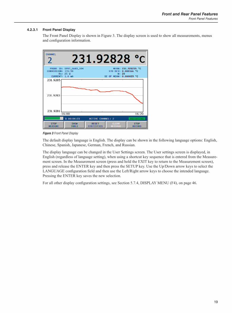
19
Front and Rear Panel FeaturesFront Panel Features
4.2.3.1 Front Panel Display
The Front Panel Display is shown in Figure 3. The display screen is used to show all measurements, menus and configuration information.
Figure 3 Front Panel Display
The default display language is English. The display can be shown in the following language options: English, Chinese, Spanish, Japanese, German, French, and Russian.
The display language can be changed in the User Settings screen. The User settings screen is displayed, in English (regardless of language setting), when using a shortcut key sequence that is entered from the Measure-ment screen. In the Measurement screen (press and hold the EXIT key to return to the Measurement screen), press and release the ENTER key and then press the SETUP key. Use the Up/Down arrow keys to select the LANGUAGE configuration field and then use the Left/Right arrow keys to choose the intended language. Pressing the ENTER key saves the new selection.
For all other display configuration settings, see Section 5.7.4, DISPLAY MENU (F4), on page 46.
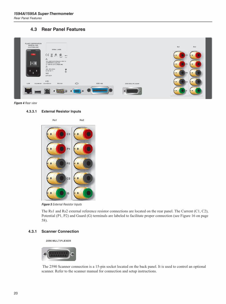
1594A/1595A Super-ThermometerRear Panel Features
20
4.3 Rear Panel Features
Figure 4 Rear view
4.3.3.1 External Resistor Inputs
Figure 5 External Resistor Inputs
The Rs1 and Rs2 external reference resistor connections are located on the rear panel. The Current (C1, C2), Potential (P1, P2) and Guard (G) terminals are labeled to facilitate proper connection (see Figure 16 on page 58).
4.3.1 Scanner Connection
The 2590 Scanner connection is a 15-pin socket located on the back panel. It is used to control an optional scanner. Refer to the scanner manual for connection and setup instructions.
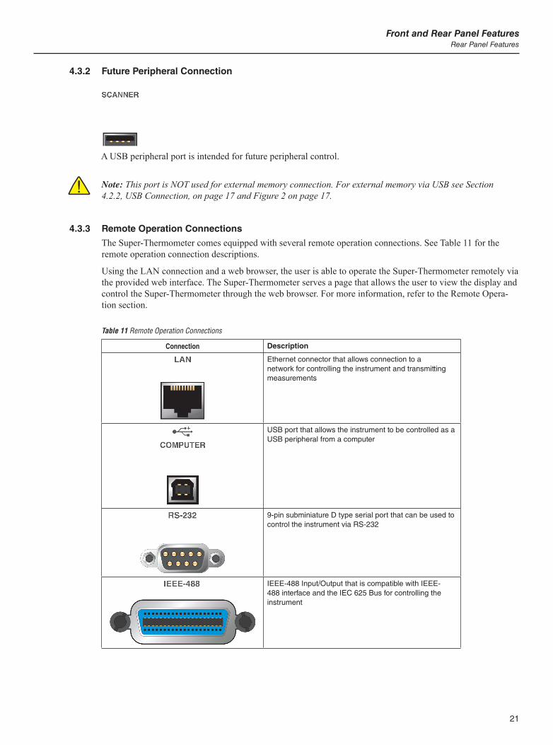
21
Front and Rear Panel FeaturesRear Panel Features
4.3.2 Future Peripheral Connection
A USB peripheral port is intended for future peripheral control.
Note: This port is NOT used for external memory connection. For external memory via USB see Section 4.2.2, USB Connection, on page 17 and Figure 2 on page 17.
4.3.3 Remote Operation Connections
The Super-Thermometer comes equipped with several remote operation connections. See Table 11 for the remote operation connection descriptions.
Using the LAN connection and a web browser, the user is able to operate the Super-Thermometer remotely via the provided web interface. The Super-Thermometer serves a page that allows the user to view the display and control the Super-Thermometer through the web browser. For more information, refer to the Remote Opera-tion section.
Table 11 Remote Operation Connections
Connection Description
Ethernet connector that allows connection to a network for controlling the instrument and transmitting measurements
USB port that allows the instrument to be controlled as a USB peripheral from a computer
9-pin subminiature D type serial port that can be used to control the instrument via RS-232
IEEE-488 Input/Output that is compatible with IEEE-488 interface and the IEC 625 Bus for controlling the instrument
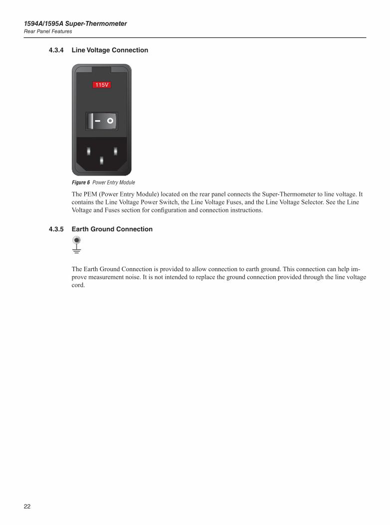
1594A/1595A Super-ThermometerRear Panel Features
22
4.3.4 Line Voltage Connection
Figure 6 Power Entry Module
The PEM (Power Entry Module) located on the rear panel connects the Super-Thermometer to line voltage. It contains the Line Voltage Power Switch, the Line Voltage Fuses, and the Line Voltage Selector. See the Line Voltage and Fuses section for configuration and connection instructions.
4.3.5 Earth Ground Connection
The Earth Ground Connection is provided to allow connection to earth ground. This connection can help im-prove measurement noise. It is not intended to replace the ground connection provided through the line voltage cord.
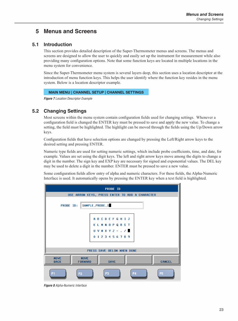
23
Menus and ScreensChanging Settings
5 Menus and Screens
5.1 IntroductionThis section provides detailed description of the Super-Thermometer menus and screens. The menus and screens are designed to allow the user to quickly and easily set up the instrument for measurement while also providing many configuration options. Note that some function keys are located in multiple locations in the menu system for convenience.
Since the Super-Thermometer menu system is several layers deep, this section uses a location descriptor at the introduction of menu function keys. This helps the user identify where the function key resides in the menu system. Below is a location descriptor example.
MAIN MENU | CHANNEL SETUP | CHANNEL SETTINGS
Figure 7 Location Descriptor Example
5.2 Changing SettingsMost screens within the menu system contain configuration fields used for changing settings. Whenever a configuration field is changed the ENTER key must be pressed to save and apply the new value. To change a setting, the field must be highlighted. The highlight can be moved through the fields using the Up/Down arrow keys.
Configuration fields that have selection options are changed by pressing the Left/Right arrow keys to the desired setting and pressing ENTER.
Numeric type fields are used for setting numeric settings, which include probe coefficients, time, and date, for example. Values are set using the digit keys. The left and right arrow keys move among the digits to change a digit in the number. The sign key and EXP key are necessary for signed and exponential values. The DEL key may be used to delete a digit in the number. ENTER must be pressed to save a new value.
Some configuration fields allow entry of alpha and numeric characters. For these fields, the Alpha-Numeric Interface is used. It automatically opens by pressing the ENTER key when a text field is highlighted.
Figure 8 Alpha-Numeric Interface

1594A/1595A Super-ThermometerPassword Protection
24
In the Alpha-Numeric Interface, use the front panel arrow keys to move the cursor to the desired character. Press the ENTER key to enter the selected character in the text edit box. Numeric characters can be entered using the Alpha-Numeric Interface or the front panel digit keys.
If a mistake is made, pressing the DELETE key will backspace over the character to the left of the cursor. When the cursor is placed over a character in the text edit box, the DELETE key will delete the character where it is located.
Use function keys MOVE BACK (F1) and MOVE FORWARD (F2) to move the cursor left or right in the text edit box. Use function keys SAVE (F3) and CANCEL (F5) to save or cancel the changes that have been made to the text field. The EXIT key will also exit the Alpha-Numeric Interface with no changes saved.
5.3 Password ProtectionSome screens by default are password protected while others may be password protected depending on con-figuration settings. A screen that is password protected will open with edit ability only if a four-digit password is entered. Otherwise, the screen will open with view only. (see Section 5.7.7.1, PASSWORD (F4), on page 54).
5.4 Menu NavigationThe following are important items to help the user understand how to navigate the menu system:
The Main Menu of the menu system may be accessed from the Measurement Screen (and most other screens) by pressing the MENU key.
Function Keys (F1, F2, F3, F4, F5) are used to select menus, functions, and in some cases, to toggle settings.
The EXIT key is used to exit a screen or menu and return to the parent screen. In most screens, pressing and holding the EXIT key for a moment returns directly to the Measurement Screen.
Menus and screens contain help text that clarify the purpose of the menu or screen. When any setting is changed in a screen, the ENTER key must be pressed to save the change. When a field requires alpha-numeric character input, the Alpha-Numeric Interface opens automatically
upon pressing ENTER when the field is highlighted. Some screens may be password protected. If the password is required, a special password screen will
appear. More information concerning password protection is found in the System Menu section. The SETUP key provides a shortcut to the Channel Setup screen, Section 5.7.1, CHANNEL SETUP
(F1), on page 29. Pressing ENTER, then SETUP provides a shortcut to the User Settings screen, Section 5.7.4.1, USER
SETTINGS (F1), on page 47, where the language setting and other user settings are located. The User Settings screen will appear as the initial screen if the Start-Up Help setting is enabled
(see Section 5.7.4.1, USER SETTINGS (F1), on page 47). This assists a first-time user in setting preferences and the system clock.
5.5 Menu SystemThe following is an outline of the menu system:Measurement Screen|MAIN MENU (MENU key) CHANNEL SETUP (SETUP key) | ASSIGN PROBE (see PROBE MENU below) | CHANNEL SETTINGS | | SET UP Rs | | ASSIGN RESISTOR | | DEFINE RESISTOR | | | ADD RESISTOR | | | EDIT RESISTOR

25
Menus and ScreensMeasurement Screen
| | | READ RESISTOR | | MANAGE RESISTORS | | READ FILE | | WRITE FILE | | MOVE UP | | MOVE DOWN | | DELETE RESISTOR | ON/OFF | MEASURE MENU (see MEASURE MENU below) PROBE MENU | ADD PROBE | COPY PROBE | EDIT PROBE | | TEST CALCULATION | READ PROBE | MANAGE PROBES | READ FILE | WRITE FILE | MOVE UP | MOVE DOWN | DELETE PROBE MEASURE MENU | SCAN SETTINGS | TIMING SETTINGS | DIGITAL FILTER | | CLEAR FILTER | RECORDING MENU | | RECORDING SETTINGS | | VIEW DATA | | READ FILE | | WRITE FILE | | ERASE DATA | ZERO-POWER MEASUREMENT DISPLAY MENU | USER SETTINGS | FIELD SETTINGS | STATISTICS SETTINGS | GRAPH SETTINGS | TEMPERATURE UNIT SYSTEM MENU TIME DATE REMOTE INTERFACE | SERIAL | USB | NETWORK | IEEE-488 | ERRORS CONFIG | STORE CONFIG | RECALL CONFIG | DELETE CONFIG | RESTORE DEFAULT | UPDATE FIRMWARE PASSWORD CALIBRATION SYSTEM TEST CURRENT TEST RATIO CALIBRATION RESISTANCE CALIBRATION CALIBRATION PARAMETERS
5.6 Measurement ScreenThe Measurement Screen contains the function keys and display fields needed for typical measurement opera-tion. It is the screen displayed after power-up unless the Start-Up Help setting is enabled (see Section 5.7.4.1, USER SETTINGS (F1), on page 47). It may be recalled other screens by pressing and holding the EXIT key
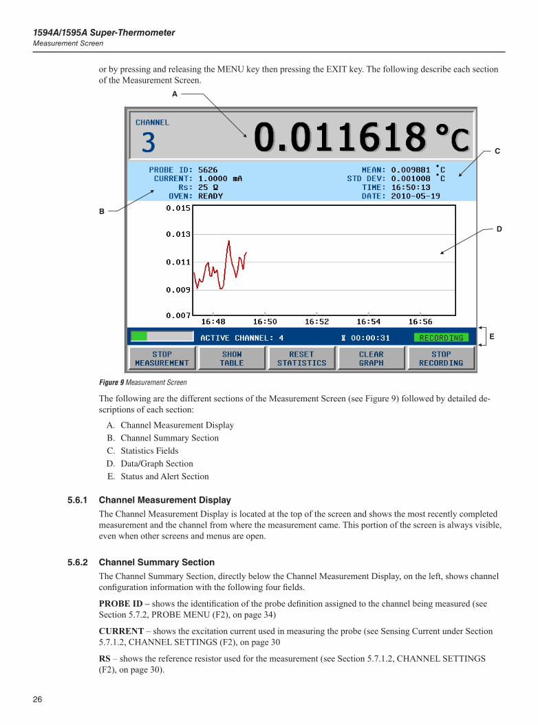
1594A/1595A Super-ThermometerMeasurement Screen
26
or by pressing and releasing the MENU key then pressing the EXIT key. The following describe each section of the Measurement Screen.
Figure 9
A
B
C
D
E
Measurement Screen
The following are the different sections of the Measurement Screen (see Figure 9) followed by detailed de-scriptions of each section:
A. Channel Measurement Display
B. Channel Summary Section
C. Statistics Fields
D. Data/Graph Section
E. Status and Alert Section
5.6.1 Channel Measurement Display
The Channel Measurement Display is located at the top of the screen and shows the most recently completed measurement and the channel from where the measurement came. This portion of the screen is always visible, even when other screens and menus are open.
5.6.2 Channel Summary Section
The Channel Summary Section, directly below the Channel Measurement Display, on the left, shows channel configuration information with the following four fields.
PROBE ID – shows the identification of the probe definition assigned to the channel being measured (see Section 5.7.2, PROBE MENU (F2), on page 34)
CURRENT – shows the excitation current used in measuring the probe (see Sensing Current under Section 5.7.1.2, CHANNEL SETTINGS (F2), on page 30
RS – shows the reference resistor used for the measurement (see Section 5.7.1.2, CHANNEL SETTINGS (F2), on page 30).
27
Menus and ScreensMeasurement Screen
OVEN - indicates whether the resistor oven is stable and ready for measurement. After power up, the OVEN field will first indicate “SETTLING” while the oven warms up and settles to the proper temperature. When the oven temperature is stable, the field will display “READY” to indicate that the Super-Thermometer is ready for measurement. It typically takes about 30 minutes for the temperature to settle and the indication to change to “READY.” If only external reference resistors are used, it is not necessary to wait for the oven to settle.
5.6.3 Statistics Fields
The Statistics Fields section of the display contains user-selectable statistics fields associated with the cur-rently displayed measurement (see Section 5.7.4.2, FIELD SETTINGS (F2), on page 48)
The Statistics Fields are displayed during measurement regardless whether Graph or Data display mode is selected. The fields are reset when the RESET STATISTICS (F3) function key is selected.
5.6.4 Data/Graph Section
The Data/Graph section displays either a data table for each active channel as it is measured or a graph of each channel’s measurement trend. The display is toggled from Data to Graph mode by pressing the SHOW DATA/GRAPH (F2) function.
When the data table is selected, the Up/Down arrow keys are used to scroll through the data table to view channels off the screen. The data fields are reset when the RESET STATISTICS (F3) function key is selected.
The graph settings are configured in the Graph Settings Screen, see Section 5.7.4.4, GRAPH SETTINGS (F4), on page 49. The graph window can be configured to display a separate graph for each channel or all chan-nels on one graph.
5.6.5 Status and Alert Section
The Status and Alert section resides at the bottom of the display above the function keys. Depending on the situation, the following are displayed in the Status and Alert section:
Measurement Progress Bar- indicates the progress of the current measurement
Countdown Timer- shows the time remaining before measurement stops. The timer is set in the Timing Set-tings screen of the Measure menu see Section 5.7.3.2, TIMING SETTINGS (F2), on page 39. If measure-ment is stopped and restarted, the timer starts over again.
Active Channel- indicates the channel currently being measured. When the measurement is completed, the measurement value and channel number will appear in the channel measurement display.
Recording Status- indicates whether recording is in progress.
Alert Messages- displays alert messages. Alert messages only appear when the Measurement Screen is dis-played. See the following table for a list of alert messages. When an alert message is displayed, the CLEAR MESSAGE (F4) function key may be pressed to clear the message.
Table 12 Alert Messages
Priority Message Description
1 RECORDING ERROR A recording error occurred, such as memory full or USB device was removed, that prevents further recording.
2 MAXIMUM TEMPERATURE EXCEEDED
The measured temperature exceeds the Maximum Temperature setting specified in the probe definition.
3 ITS-90 SUBRANGE EXCEEDED The measured temperature is outside either of the selected ITS-90 subranges in the probe definition.
4 RESISTOR DUE FOR CALIBRATION The Rs resistor used for the measurement is due for calibration; as specified by the Due Date setting in the resistor definition.
The following function keys are located in the Measurement screen:
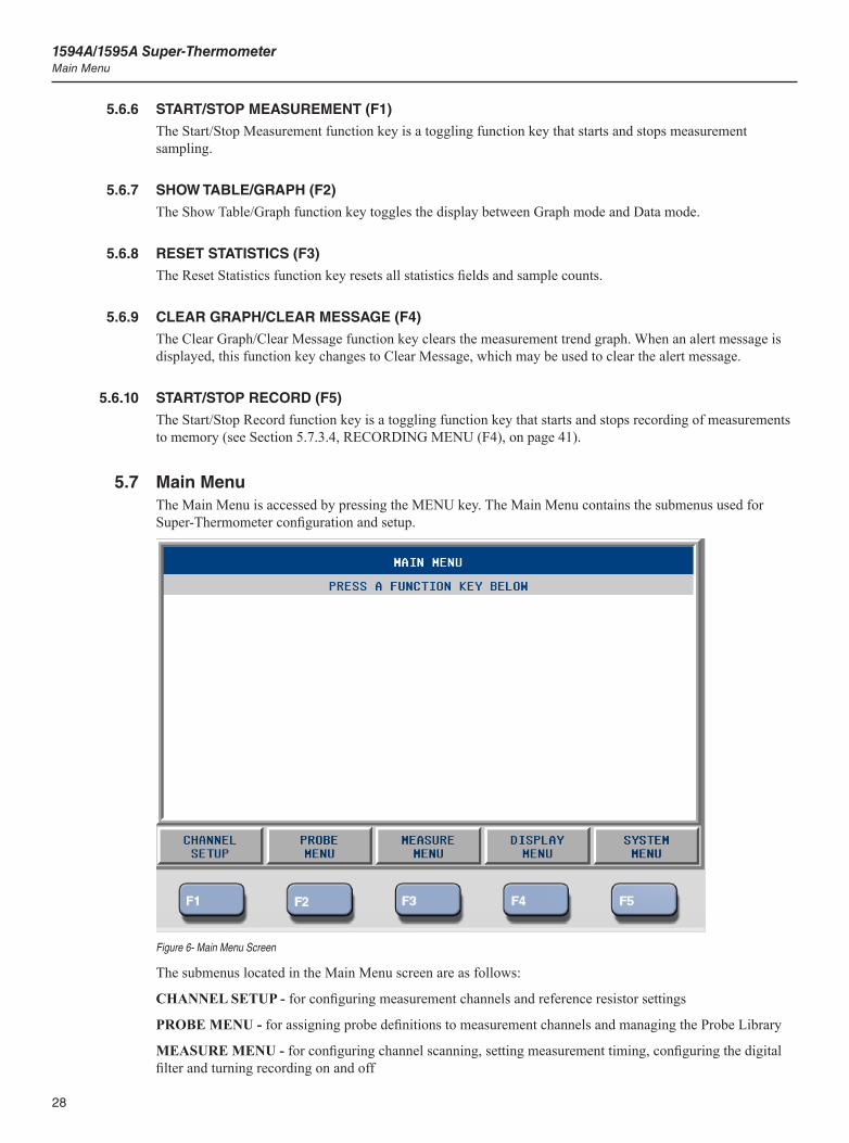
1594A/1595A Super-ThermometerMain Menu
28
5.6.6 START/STOP MEASUREMENT (F1)
The Start/Stop Measurement function key is a toggling function key that starts and stops measurement sampling.
5.6.7 SHOW TABLE/GRAPH (F2)
The Show Table/Graph function key toggles the display between Graph mode and Data mode.
5.6.8 RESET STATISTICS (F3)
The Reset Statistics function key resets all statistics fields and sample counts.
5.6.9 CLEAR GRAPH/CLEAR MESSAGE (F4)
The Clear Graph/Clear Message function key clears the measurement trend graph. When an alert message is displayed, this function key changes to Clear Message, which may be used to clear the alert message.
5.6.10 START/STOP RECORD (F5)
The Start/Stop Record function key is a toggling function key that starts and stops recording of measurements to memory (see Section 5.7.3.4, RECORDING MENU (F4), on page 41).
5.7 Main MenuThe Main Menu is accessed by pressing the MENU key. The Main Menu contains the submenus used for Super-Thermometer configuration and setup.
Figure 6- Main Menu Screen
The submenus located in the Main Menu screen are as follows:
CHANNEL SETUP - for configuring measurement channels and reference resistor settings
PROBE MENU - for assigning probe definitions to measurement channels and managing the Probe Library
MEASURE MENU - for configuring channel scanning, setting measurement timing, configuring the digital filter and turning recording on and off

29
Menus and ScreensMain Menu
DISPLAY MENU - used to configure display settings, and statistics settings as well as selecting temperature measurement units
SYSTEM MENU - used to configure the remote interface ports, set the system date and time, configure pass-word settings and calibrate the Super-Thermometer
The following are detailed descriptions of each submenu and its contents.
5.7.1 CHANNEL SETUP (F1)
MAIN MENU |
The Channel Setup menu is used for configuring measurement channels and reference resistor settings. The Channel Setups screen shows each channel and its settings. Pressing the SETUP key on the front panel will access the Channel Setup screen directly from any other screen or menu.
For convenience, the MEASURE MENU (F4) function key is included in this menu as well as the Main Menu. The Measure Menu is described in full detail after the Probe Menu section.
Figure 10 Channel Setup Screen
Using the Up/Down arrow keys, the user selects the channel to be configured. Pressing the ON/OFF (F3) func-tion key enables (ON) or disables (OFF) the selected channel. Only one channel can be enabled unless SCAN ENABLE is set to ON (see Section 5.7.3.1, SCAN SETTINGS (F1), on page 39). A channel that is disabled will be skipped when SCAN ENABLE is set to ON. A channel can also be enabled by pressing the corre-sponding Channel Select Key on the front panel.
The following function keys are used to configure the channels.
5.7.1.1 ASSIGN PROBE (F1)
MAIN MENU | CHANNEL SETUP |
The Assign Probe function key allows the user to assign a predefined probe definition to the selected channel.
Upon pressing the Assign Probe function key, the Probe Library is displayed. Using the Up/Down arrow keys, the desired probe definition is highlighted. Pressing ENTER assigns the probe definition to the previously selected channel. For convenience, the function keys needed for editing the Probe Library are included in the Assign Probe screen. These function keys are described in detail in the Probe Menu section.
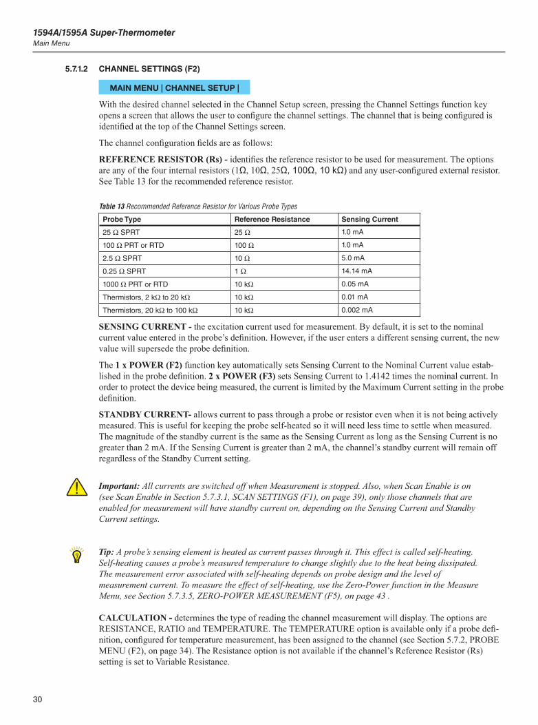
1594A/1595A Super-ThermometerMain Menu
30
5.7.1.2 CHANNEL SETTINGS (F2)
MAIN MENU | CHANNEL SETUP |
With the desired channel selected in the Channel Setup screen, pressing the Channel Settings function key opens a screen that allows the user to configure the channel settings. The channel that is being configured is identified at the top of the Channel Settings screen.
The channel configuration fields are as follows:
REFERENCE RESISTOR (Rs) - identifies the reference resistor to be used for measurement. The options are any of the four internal resistors (1Ω, 10Ω, 25Ω, 100Ω, 10 kΩ) and any user-configured external resistor. See Table 13 for the recommended reference resistor.
Table 13 Recommended Reference Resistor for Various Probe Types
Probe Type Reference Resistance Sensing Current
25 W SPRT 25 W 1.0 mA
100 W PRT or RTD 100 W 1.0 mA
2.5 W SPRT 10 W 5.0 mA
0.25 W SPRT 1 W 14.14 mA
1000 W PRT or RTD 10 kW 0.05 mA
Thermistors, 2 kW to 20 kW 10 kW 0.01 mA
Thermistors, 20 kW to 100 kW 10 kW 0.002 mA
SENSING CURRENT - the excitation current used for measurement. By default, it is set to the nominal current value entered in the probe’s definition. However, if the user enters a different sensing current, the new value will supersede the probe definition.
The 1 x POWER (F2) function key automatically sets Sensing Current to the Nominal Current value estab-lished in the probe definition. 2 x POWER (F3) sets Sensing Current to 1.4142 times the nominal current. In order to protect the device being measured, the current is limited by the Maximum Current setting in the probe definition.
STANDBY CURRENT- allows current to pass through a probe or resistor even when it is not being actively measured. This is useful for keeping the probe self-heated so it will need less time to settle when measured. The magnitude of the standby current is the same as the Sensing Current as long as the Sensing Current is no greater than 2 mA. If the Sensing Current is greater than 2 mA, the channel’s standby current will remain off regardless of the Standby Current setting.
Important: All currents are switched off when Measurement is stopped. Also, when Scan Enable is on (see Scan Enable in Section 5.7.3.1, SCAN SETTINGS (F1), on page 39), only those channels that are enabled for measurement will have standby current on, depending on the Sensing Current and Standby Current settings.
Tip: A probe’s sensing element is heated as current passes through it. This effect is called self-heating. Self-heating causes a probe’s measured temperature to change slightly due to the heat being dissipated. The measurement error associated with self-heating depends on probe design and the level of measurement current. To measure the effect of self-heating, use the Zero-Power function in the Measure Menu, see Section 5.7.3.5, ZERO-POWER MEASUREMENT (F5), on page 43 .
CALCULATION - determines the type of reading the channel measurement will display. The options are RESISTANCE, RATIO and TEMPERATURE. The TEMPERATURE option is available only if a probe defi-nition, configured for temperature measurement, has been assigned to the channel (see Section 5.7.2, PROBE MENU (F2), on page 34). The Resistance option is not available if the channel’s Reference Resistor (Rs) setting is set to Variable Resistance.

31
Menus and ScreensMain Menu
5.7.1.2.1 SET UP Rs (F1)
MAIN MENU | CHANNEL SETUP | CHANNEL SETTINGS |
Pressing the Set Up Rs function key displays the Rs definition assigned to each Rs input. The Up/Down arrow keys are used to scroll through the list to select an Rs input for configuration. The following function keys al-low the user to configure the Rs input.
5.7.1.2.1.1 ASSIGN RESISTOR (F1)
MAIN MENU | CHANNEL SETUP | CHANNEL SETTINGS | SET UP Rs |
The Assign Resistor function key opens the resistor definition library. This is a list of Rs configurations that have been created by the user. The resistor definition library may contain up to 50 resistor definitions. Every definition in the library must have a unique ID.
Also displayed in the resistor definition library, at the end of the list, are factory default options VARIABLE RESISTANCE and NO RESISTOR.
The VARIABLE RESISTANCE option is used when the Rs resistance will vary such as when a SPRT is being used as a reference resistor. When in this mode, measurement output will be in ratio only.
If the NO RESISTOR option is chosen, the Rs Input cannot be used as a reference resistor connection.
5.7.1.2.1.1.1 DEFINE RESISTOR (F2)
MAIN MENU | CHANNEL SETUP | CHANNEL SETTINGS | SET UP Rs |
The Define Resistor function key displays the resistor definition library. The displayed function keys are used to create new Rs resistor definitions or edit definitions stored in the resistor definition library. The following describe each function key.
5.7.1.2.1.1.2 ADD RESISTOR (F1)
MAIN MENU | CHANNEL SETUP | CHANNEL SETTINGS | SET UP Rs | DEFINE RESISTOR |
The Add Resistor screen is used to create a new Rs definition using the following configuration fields and function key.
RESISTOR ID - used to identify the reference resistor. Pressing the ENTER key while the RESISTOR ID field is highlighted will open the Alpha-Numeric Interface to allow entry of a unique ID.
RESISTANCE VALUE - the resistance value of the Rs reference resistor. This resistance value is used to calculate UUT resistance so it is important that it is entered correctly.
MAXIMUM CURRENT - establishes the maximum current allowed to be applied during measurement. This prevents excessive current from being applied to the reference resistor.
CALIBRATION DATE - used to define when the reference resistor was calibrated. If not used, the digits can all be set to zeros.
DUE DATE - used to alert the user when the reference resistor is due for calibration. This is only applicable if Rs DUE ALERT is enabled in the User Settings screen, see Section 5.7.4.1, USER SETTINGS (F1), on page 47.
SAVE (F1)
The Save function key saves the settings.
CANCEL (F5)
The Cancel function key exits Add Resistor without saving changes.
1594A/1595A Super-ThermometerMain Menu
32
5.7.1.2.1.1.3 EDIT RESISTOR (F2)
MAIN MENU | CHANNEL SETUP | CHANNEL SETTINGS | SET UP Rs | DEFINE RESISTOR |
The Edit Resistor function key opens the highlighted Rs definition for editing. The configuration fields are explained in the Add Resistor section above.
5.7.1.2.1.2 READ RESISTOR (F3)
MAIN MENU | CHANNEL SETUP | CHANNEL SETTINGS | SET UP Rs | DEFINE RESISTOR |
Read Resistor allows the user to load a pre-configured reference resistor definition from a USB memory device.
To load a resistor definition, insert a USB memory device that contains a resistor configuration into the front panel. Allow about 10 seconds for the system to recognize the USB device and then press OK (F5). A list of resistor definition files stored on the memory device appears on the screen. Scroll through the list using the Up/Down arrow keys and select the file to be loaded. Press OK (F5) to begin the file transfer. A message will prompt the user to continue.
Tip: Resistor definition files must be located in a folder named “\159x\resistor” on the USB memory device. The files must have the extension “.res” and contain resistor definition data in the proper format. This type of file can be created by using the Write File function, see Section 5.7.1.2.1.3.2, WRITE FILE (F2), on page 32 in the Manage Resistors menu.
5.7.1.2.1.3 MANAGE RESISTORS (F3)
MAIN MENU | CHANNEL SETUP | CHANNEL SETTINGS | SET UP Rs |
Rs resistor definitions in the resistor definition library may be added, deleted, or prioritized in the Manage Resistors menu using the following function keys.
5.7.1.2.1.3.1 READ FILE (F1)
MAIN MENU | CHANNEL SETUP | CHANNEL SETTINGS | SET UP Rs | MANAGE RESISTORS
The Read File function key allows the user to import an entire set of resistor definitions from a file on a USB memory device.
Every resistor definition in the resistor definition library must have a unique ID. If a resistor definition in the library has the same ID as one read from the USB memory device, it will be replaced.
Tip: Resistor definition files must be located in a folder named “\159x\resistor” on the USB memory device. The files must have the extension “.res” and contain resistor definition data in the proper format. This type of file can be created by using the Write File function, see Section 5.7.1.2.1.3.2, WRITE FILE (F2), on page 32 in the Manage Resistors menu.
5.7.1.2.1.3.2 WRITE FILE (F2)
MAIN MENU | CHANNEL SETUP | CHANNEL SETTINGS | SET UP Rs | MANAGE RESISTORS
The Write File function key in the Manage Resistors menu allows the user to export one resistor definition or the entire library to a file on a USB memory device.
If a resistor was selected in the Manage Resistors screen, that resistor definition will be written to a file. If ALL RESISTORS was selected, the entire Resistor Library will be written to a file.
The screen shows the name of the file to be written. The user may change the name of the file by pressing ENTER to open the alpha-numeric editing screen. Finally, the user presses the CONTINUE function key to
33
Menus and ScreensMain Menu
write the file. If a USB memory device has not yet been inserted, the user is instructed to do so. Allow about 10 seconds for the system to recognize the USB device before continuning.
Resistor definition files are written to a folder named “\159x\resistor” on the USB memory device and have the extension “.res”. If the file does not exist, it will be created. If the file already exists and one resistor was selected, its resistor definition will be appended to the data in the file. If ALL RESISTORS was selected, the contents of the existing file will be replaced with the resistor definitions in the resistor definition library.
5.7.1.2.1.3.3 MOVE UP (F3)
MAIN MENU | CHANNEL SETUP | CHANNEL SETTINGS | SET UP Rs | MANAGE RESISTORS
The Move Up function key changes the arrangement of the reference resistors in the resistor definition library by moving the selected resistor up one position. If the first resistor is selected or if ALL RESISTORS is se-lected, there is no action.
5.7.1.2.1.3.4 MOVE DOWN (F4)
MAIN MENU | CHANNEL SETUP | CHANNEL SETTINGS | SET UP Rs | MANAGE RESISTORS
The Move Down function changes the arrangement of the reference resistors in the resistor definition library by moving the selected resistor down one position. If the last resistor is selected or if ALL RESISTORS is selected, there is no action.
5.7.1.2.1.3.5 DELETE RESISTOR (F5)
MAIN MENU | CHANNEL SETUP | CHANNEL SETTINGS | SET UP Rs | MANAGE RESISTORS
The Delete Resistor function key may be used to delete a resistor definition from the resistor definition library.
If a resistor was selected in the Manage Resistors screen, that resistor will be deleted. If ALL RESISTORS was selected, the entire library will be erased.
A message appears prompting the user to confirm the delete operation. The user may press the YES func-tion key to confirm and proceed with deleting the resistor definition or library. Pressing the NO function key cancels the operation and returns to the Manage Resistors menu. Pressing the EXIT key will also cancel the operation with no change.

1594A/1595A Super-ThermometerMain Menu
34
5.7.2 PROBE MENU (F2)
MAIN MENU |
Figure 11 Probe Menu Screen
The Probe Menu contains the function keys needed for editing and managing probe definitions stored in the Probe Library.
The Probe Library is non-volatile memory inside the Super-Thermometer which contains probe configura-tion information that is configured and stored by the user. A user can easily program probe parameters into the Probe Library and quickly assign the parameters to any of the measurement channels.
Tip: Once the probe definitions are programmed into the Probe Library, they can be conveniently copied to a USB memory device (see Section 5.7.2.5, MANAGE PROBES (F5), on page 37) so they can be backed up and easily reloaded if needed.
The following are descriptions of each function key in the Probe Menu.
5.7.2.1 ADD PROBE (F1)
MAIN MENU | PROBE MENU |
The Add Probe screen is used to add a new probe definition to the Probe Library. Up to 100 definitions can be stored in the Probe Library. If the limit has been reached, the user will not be allowed to add more probe definitions.
The following fields are used to define a probe configuration:
ID - is the probe ID field. The user may enter alpha or numeric characters to enter a unique probe ID up to 24 characters in length. Duplicate probe IDs cannot be saved. With the ID field selected, pressing ENTER will open the Alpha-Numeric Interface allowing the user to enter the probe ID.
TYPE - defines the type of probe. The options are PRT, THERMISTOR, and RESISTOR. The type selected will determine what other probe configuration fields appear.
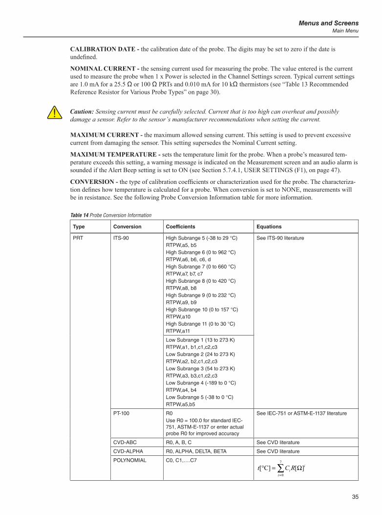
35
Menus and ScreensMain Menu
CALIBRATION DATE - the calibration date of the probe. The digits may be set to zero if the date is undefined.
NOMINAL CURRENT - the sensing current used for measuring the probe. The value entered is the current used to measure the probe when 1 x Power is selected in the Channel Settings screen. Typical current settings are 1.0 mA for a 25.5 Ω or 100 Ω PRTs and 0.010 mA for 10 kΩ thermistors (see “Table 13 Recommended Reference Resistor for Various Probe Types” on page 30).
Caution: Sensing current must be carefully selected. Current that is too high can overheat and possibly damage a sensor. Refer to the sensor’s manufacturer recommendations when setting the current.
MAXIMUM CURRENT - the maximum allowed sensing current. This setting is used to prevent excessive current from damaging the sensor. This setting supersedes the Nominal Current setting.
MAXIMUM TEMPERATURE - sets the temperature limit for the probe. When a probe’s measured tem-perature exceeds this setting, a warning message is indicated on the Measurement screen and an audio alarm is sounded if the Alert Beep setting is set to ON (see Section 5.7.4.1, USER SETTINGS (F1), on page 47).
CONVERSION - the type of calibration coefficients or characterization used for the probe. The characteriza-tion defines how temperature is calculated for a probe. When conversion is set to NONE, measurements will be in resistance. See the following Probe Conversion Information table for more information.
Table 14 Probe Conversion Information
Type Conversion Coefficients Equations
PRT ITS-90 High Subrange 5 (-38 to 29 °C)RTPW,a5, b5High Subrange 6 (0 to 962 °C)RTPW,a6, b6, c6, dHigh Subrange 7 (0 to 660 °C)RTPW,a7, b7, c7High Subrange 8 (0 to 420 °C)RTPW,a8, b8High Subrange 9 (0 to 232 °C)RTPW,a9, b9 High Subrange 10 (0 to 157 °C)RTPW,a10High Subrange 11 (0 to 30 °C)RTPW,a11
See ITS-90 literature
Low Subrange 1 (13 to 273 K)RTPW,a1, b1,c1,c2,c3Low Subrange 2 (24 to 273 K)RTPW,a2, b2,c1,c2,c3Low Subrange 3 (54 to 273 K)RTPW,a3, b3,c1,c2,c3Low Subrange 4 (-189 to 0 °C)RTPW,a4, b4Low Subrange 5 (-38 to 0 °C)RTPW,a5,b5
PT-100 R0Use R0 = 100.0 for standard IEC-751, ASTM-E-1137 or enter actual probe R0 for improved accuracy
See IEC-751 or ASTM-E-1137 literature
CVD-ABC R0, A, B, C See CVD literature
CVD-ALPHA R0, ALPHA, DELTA, BETA See CVD literature
POLYNOMIAL C0, C1,….C7
t C Rii
i[ ] [ ]°C ==∑
0
7
Ω
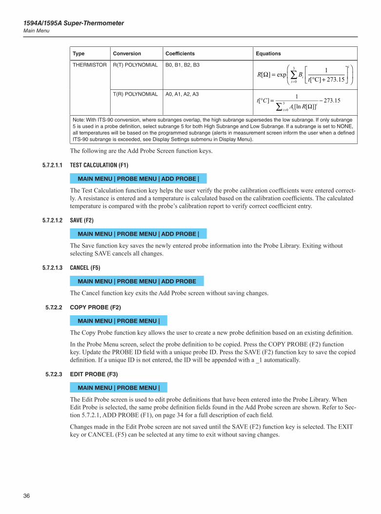
1594A/1595A Super-ThermometerMain Menu
36
Type Conversion Coefficients Equations
THERMISTOR R(T) POLYNOMIAL B0, B1, B2, B3
R Bti
i
i
[ ] exp[ ] .
Ω =+
=∑
0
3 1273 15°C
T(R) POLYNOMIAL A0, A1, A2, A3t C
A R ii
[ ][ln [ ]]
.° = −=∑
1 273 1510
3Ω
Note: With ITS-90 conversion, where subranges overlap, the high subrange supersedes the low subrange. If only subrange 5 is used in a probe definition, select subrange 5 for both High Subrange and Low Subrange. If a subrange is set to NONE, all temperatures will be based on the programmed subrange (alerts in measurement screen inform the user when a defined ITS-90 subrange is exceeded, see Display Settings submenu in Display Menu).
The following are the Add Probe Screen function keys.
5.7.2.1.1 TEST CALCULATION (F1)
MAIN MENU | PROBE MENU | ADD PROBE |
The Test Calculation function key helps the user verify the probe calibration coefficients were entered correct-ly. A resistance is entered and a temperature is calculated based on the calibration coefficients. The calculated temperature is compared with the probe’s calibration report to verify correct coefficient entry.
5.7.2.1.2 SAVE (F2)
MAIN MENU | PROBE MENU | ADD PROBE |
The Save function key saves the newly entered probe information into the Probe Library. Exiting without selecting SAVE cancels all changes.
5.7.2.1.3 CANCEL (F5)
MAIN MENU | PROBE MENU | ADD PROBE
The Cancel function key exits the Add Probe screen without saving changes.
5.7.2.2 COPY PROBE (F2)
MAIN MENU | PROBE MENU |
The Copy Probe function key allows the user to create a new probe definition based on an existing definition.
In the Probe Menu screen, select the probe definition to be copied. Press the COPY PROBE (F2) function key. Update the PROBE ID field with a unique probe ID. Press the SAVE (F2) function key to save the copied definition. If a unique ID is not entered, the ID will be appended with a _1 automatically.
5.7.2.3 EDIT PROBE (F3)
MAIN MENU | PROBE MENU |
The Edit Probe screen is used to edit probe definitions that have been entered into the Probe Library. When Edit Probe is selected, the same probe definition fields found in the Add Probe screen are shown. Refer to Sec-tion 5.7.2.1, ADD PROBE (F1), on page 34 for a full description of each field.
Changes made in the Edit Probe screen are not saved until the SAVE (F2) function key is selected. The EXIT key or CANCEL (F5) can be selected at any time to exit without saving changes.
37
Menus and ScreensMain Menu
5.7.2.4 READ PROBE (F4)
MAIN MENU | PROBE MENU |
The Read Probe function key allows the user to read a probe definition from the USB memory device into the Probe Library.
When a USB memory device, that contains a probe definition file, is inserted in the front panel, the Read Probe screen displays a list of probe definition files (*.prb) found on the memory device. By scrolling up and down the list using the arrow keys, the user can select the desired probe definition file. Pressing the ENTER key (with the file selected) will open the file and display the probe definitions it contains. At this point a probe definition can be selected and read into the Probe Library by pressing the ENTER key again.
If the selected probe definition in the USB memory device has the same ID as a probe definition that already exists in the Probe Library, a warning message appears warning that the probe definition in the library will be replaced. The user may press the YES function key to update the probe definition and exit, or press NO (or the EXIT key) to return to the Assign Probe screen.
Tip: Probe definition files must be located in a folder named “\159x\probe\” on the USB memory device. The files must have the extension “.prb” and contain probe definition data in the proper format. This type of file can be created by using the Write File function in the Manage Probes menu.
5.7.2.5 MANAGE PROBES (F5)
MAIN MENU | PROBE MENU |
The Manage Probes screen is used for reading probe definition files from memory, writing definition files to memory, moving probe definition locations in the Probe Library and deleting probe definitions.
In the Manage Probe screen, the Probe Library is displayed as well as the following function keys.
5.7.2.5.1 READ FILE (F1)
MAIN MENU | PROBE MENU | MANAGE PROBES |
The Read File function key allows the user to read a probe definition file (.prb) from the USB memory device. A probe definition file may contain multiple probe definition files. The files have to be located in the folder \159x\probe\ in the memory device and have the extension .prb.
A file is read by inserting a memory device containing a valid probe definition file into the front panel. When READ FILE (F1) is pressed, a list of all probe files that reside on the memory device is shown. The file is se-lected by using the using the arrow keys. The file is transferred to the Probe Library upon pressing the ENTER key and confirming the action.
Important: Any probe definition in the Probe Library that has the same ID as any probe definition in the memory device will be overwritten.
5.7.2.5.2 WRITE FILE (F2)
MAIN MENU | PROBE MENU | MANAGE PROBES |
The Write File function key exports one probe definition file or the entire Probe Library from the Super-Ther-mometer to the USB memory device.
When in the Manage Probes screen, select either a single probe definition or ALL PROBES (at the end of the list). When WRITE FILE (F2) is selected, the name of the file to which the definitions will be written is displayed. Pressing the ENTER key will open the Alpha-Numeric Interface so the file name can be entered. Pressing CONTINUE (F1) writes the file to memory.
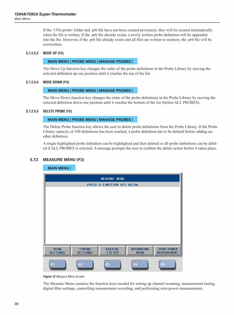
1594A/1595A Super-ThermometerMain Menu
38
If the \159x\probe\ folder and .prb file have not been created previously, they will be created automatically when the file is written. If the .prb file already exists, a newly written probe definition will be appended into the file. However, if the .prb file already exists and all files are written to memory, the .prb file will be overwritten.
5.7.2.5.3 MOVE UP (F3)
MAIN MENU | PROBE MENU | MANAGE PROBES |
The Move Up function key changes the order of the probe definitions in the Probe Library by moving the selected definition up one position until it reaches the top of the list.
5.7.2.5.4 MOVE DOWN (F4)
MAIN MENU | PROBE MENU | MANAGE PROBES |
The Move Down function key changes the order of the probe definitions in the Probe Library by moving the selected definition down one position until it reaches the bottom of the list (before ALL PROBES).
5.7.2.5.5 DELETE PROBE (F5)
MAIN MENU | PROBE MENU | MANAGE PROBES |
The Delete Probe function key allows the user to delete probe definitions from the Probe Library. If the Probe Library capacity of 100 definitions has been reached, a probe definition has to be deleted before adding an-other definition.
A single highlighted probe definition can be highlighted and then deleted or all probe definitions can be delet-ed if ALL PROBES is selected. A message prompts the user to confirm the delete action before it takes place.
5.7.3 MEASURE MENU (F3)
MAIN MENU |
Figure 12 Measure Menu Screen
The Measure Menu contains the function keys needed for setting up channel scanning, measurement timing, digital filter settings, controlling measurement recording, and performing zero-power measurements.
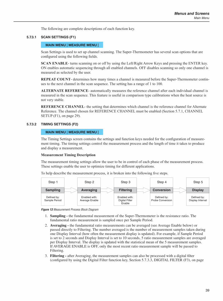
39
Menus and ScreensMain Menu
The following are complete descriptions of each function key.
5.7.3.1 SCAN SETTINGS (F1)
MAIN MENU | MEASURE MENU |
Scan Settings is used to set up channel scanning. The Super-Thermometer has several scan options that are configured using the following fields.
SCAN ENABLE- turns scanning on or off by using the Left/Right Arrow Keys and pressing the ENTER key. ON enables automatic sequencing through all enabled channels. OFF disables scanning so only one channel is measured as selected by the user.
REPEAT COUNT- determines how many times a channel is measured before the Super-Thermometer contin-ues to the next channel in the scan sequence. The setting has a range of 1 to 100.
ALTERNATE REFERENCE- automatically measures the reference channel after each individual channel is measured in the scan sequence. This feature is useful in comparison type calibrations when the heat source is not very stable.
REFERENCE CHANNEL- the setting that determines which channel is the reference channel for Alternate Reference. The channel chosen for REFERENCE CHANNEL must be enabled (Section 5.7.1, CHANNEL SETUP (F1), on page 29).
5.7.3.2 TIMING SETTINGS (F2)
MAIN MENU | MEASURE MENU |
The Timing Settings screen contains the settings and function keys needed for the configuration of measure-ment timing. The timing settings control the measurement process and the length of time it takes to produce and display a measurement.
Measurement Timing Description
The measurement timing settings allow the user to be in control of each phase of the measurement process. These settings enable the user to optimize timing for different applications.
To help describe the measurement process, it is broken into the following five steps.
Figure 13
Step 1
Sampling
Defined by:Sample Period
Step 2
Averaging
Enabled with:Average Enable
Step 3
Filtering
Enabled with:Digital Filter
Enable
Step 4
Conversion
Defined by:Probe Conversion
Step 5
Display
Defined by:Display Interval
Measurement Process Block Diagram
1. Sampling - the fundamental measurement of the Super-Thermometer is the resistance ratio. The fundamental ratio measurement is sampled once per Sample Period.
2. Averaging - the fundamental ratio measurements can be averaged (see Average Enable below) or passed directly to Filtering. The number averaged is the number of measurement samples taken during one Display Interval (how often the measurement display is updated). For example, if Sample Period is set to 2 seconds and Display Interval is set to 10 seconds, 5 ratio measurement samples are averaged per Display Interval. The display is updated with the statistical mean of the 5 measurement samples. If AVERAGE ENABLE is OFF, only the most recent ratio measurement sample will be passed to Filtering.
3. Filtering - after Averaging, the measurement samples can also be processed with a digital filter (configured by using the Digital Filter function key, Section 5.7.3.3, DIGITAL FILTER (F3), on page
1594A/1595A Super-ThermometerMain Menu
40
41) if the digital filter is ON. If the digital filter is OFF, measurement samples are passed directly to Conversion.
4. Conversion - after filtering, the fundamental ratio measurement can be converted to the selected unit of measure such as Temperature (Section 5.7.2.3, EDIT PROBE (F3), on page 36). If RATIO is the selected unit of conversion, the measurement is passed directly to Display.
5. Display - after conversion, the measurement is sent to the display, remote interface, statistics calculations, and memory at a rate of once per Display Interval. The statistical mean that is displayed in the Measurement screen is based on n number of displayed measurements, not number of samples.
The Timing Settings screen contains the following measurement timing fields.
SAMPLE PERIOD - sets the length of time required to obtain a fundamental ratio measurement sample. The options are 1, 2, 5, and 10 seconds. The default option is 2 seconds.
Note: When the sample period is changed, measurement will stop. It must be restarted by the user.
The 1 second option is useful for applications that require measurements at the highest possible speed, such as thermal response tests. However, it can be expected to observe greater measurement noise will be greater when using a 1 second sample period. The 2 seconds option provides good stable measurements for most types of thermometer probes. The 10 seconds option may yield better results for very high resistances or with probes that have unusually large settling effects which may be caused by electrical leakage or dielectric absorption. A probe may be tested for electrical settling by comparing measurements made with the 2 seconds and 10 seconds sample periods.
With the 1 second and 2 seconds options the sensing current is reversed at a basic interval of 0.2 second. With the 5 seconds and 10 seconds options the current is reversed at a basic interval of 1.2 seconds.
Sample Period cannot be larger than the Display Interval setting.
DISPLAY INTERVAL - determines how often measurements are passed to the display, statistics fields, memory, and remote interface ports. Possible options are 1, 2, 10, 30, and 60 seconds. The default option is 2 seconds. Changing the Display Interval setting may affect the Sample Period setting, as Sample Period cannot be greater than Display Interval.
AVERAGE ENABLE - determines whether fundamental measurement samples are averaged before being passed to the digital filter step. If Average Enable is ON, all fundamental measurements acquired during the Display Interval are combined by averaging. If Average Enable is OFF, or if Sample Period is the same as Display Interval, only a single sample, the most recent, is passed to the next step in the measurement process. The default option is ON.
STOP TIMER ENABLE - enables or disables the stop timer, which stops measurement after a specified length of time. If Stop Timer Enable is ON, the stop timer begins counting down when measurement is started using the START MEASUREMENT (F1) function key in the Measurement screen, and stops measurement au-tomatically when the timer elapses. If STOP TIMER ENABLE is OFF (default setting is OFF), measurement continues indefinitely until the user stops measurement.
When the stop timer is enabled and measurement is enabled, an hourglass symbol and the time remaining, in hours, minutes, and seconds appears at the bottom of the Measurement screen.
TIMER DURATION - sets the stop timer duration. The value is a number of hours, minutes, and seconds, ranging from 00:00:01 to 23:59:59. The default value is 01:00:00. This setting is only relevant when Stop Timer Enable is ON.
AUDIO INDICATION - enables or disables the audio alert that tells the user when the stop timer elapses and measurement stops. The default option is ON.
The Sample Period, Display Interval and Average Enable settings in the Timing Settings menu can be auto-matically configured by selecting one of the following preset function keys (a full description of each field can be found later in this section):
PRESET NORMAL (F1) - is used for most applications. This setting provides a balance between speed and precision. Sample Period and Display Interval are both set to 2 seconds and Average Enable is set to ON.
41
Menus and ScreensMain Menu
PRESET PRECISION (F2) - sets the timing settings for minimal measurement noise and settling error with most thermometer probes. Sample Period is set to 2 seconds, Display Interval is set to 10 seconds, and Aver-age Enable is set to ON.
PRESET FAST (F3) - is used to configure the Super-Thermometer for the fastest possible measurements. Sample Period and Display Interval are both set to 1 second. Measurement noise and electrical settling errors may be greater in Fast mode. Fast mode is useful for certain applications such as probe response time testing.
PRESET LONG (F4) - sets the timings settings for better results with probes that exhibit long electrical set-tling times. Measurement noise might be slightly higher. Sample period is set to 10 seconds, Display Interval is set to 10 seconds and Average is set to ON.
5.7.3.3 DIGITAL FILTER (F3)
MAIN MENU | MEASURE MENU |
The Digital Filter screen is used to change the digital filter settings and clear the digital filter buffer.
Digital Filter Description
The digital filter is a moving average filter that computes the arithmetic mean of display measurements stored in a buffer. The size of the buffer is user-defined via the Average Count setting. If the buffer is full, the oldest measurement in the buffer is discarded when a new measurement enters the buffer. If the buffer is only partly filled, the mean is still computed using the limited number of stored measurements.
If the digital filter is enabled, the most recent measurement coming from Averaging (see Measurement Se-quence Diagram in the previous section) is averaged with the previous display measurements stored in the digital filter buffer. For example, if Display Interval is set to 10 seconds, and the digital filter average count is 20, a new display measurement is averaged with the previous 19 display measurements for a window size of 200 seconds (n = 20).
The buffer is cleared when measurement is started or if a measurement is out-of-range. This may occur, for example, if a probe is disconnected from a channel. It may also be cleared by the user at any time using the CLEAR FILTER (F1) function. This clears the filter for all channels at once.
The Digital Filter configuration settings and function key are as follows:
FILTER ENABLE - enables or disables the digital filter. The default option is ON.
AVERAGE COUNT - sets the number of Display Interval measurements that are averaged by the digital filter. The setting has a range of 2 through 100. The default value is 30. This setting is only meaningful when Filter Enable is ON.
5.7.3.3.1 CLEAR FILTER (F1) - clears the filter buffer.
Tip: It is useful to use Clear Filter to clear the digital filter buffer when an abrupt change to the data has occurred. This allows the filtered measurements to settle more quickly.
5.7.3.4 RECORDING MENU (F4)
MAIN MENU | MEASURE MENU |
In the Recording Menu, the user can control how measurements are recorded to a memory device (external or internal). This menu is also used for manipulating data files including exporting of data and erasing data.
Measurements may be stored in either of two possible memory devices; Internal Memory or a external USB Memory Device. Internal memory can store up to approximately 80,000 individual measurements. A USB flash memory device can typically store an even greater quantity of data, depending on the memory size. Both types of memory devices are non-volatile, meaning the data is preserved even when the power is switched off. However, some data may be lost if the power is switched off as data is being written.
1594A/1595A Super-ThermometerMain Menu
42
Important: Avoid switching power off to the Super-Thermometer while measurement and recording are in progress or recorded data may be lost.
Measurements are recorded when the START RECORD (F5) function key in the Measurement screen has been pressed. The Status Bar at the bottom of the Measurement screen indicates if recording is ON or OFF.
Each recorded measurement includes the date and time of the measurement, channel, measured value, and unit. Additional statistical data is also recorded when the Record Statistics setting is ON.
The data written into internal memory is organized into data sets and each data set is identified by the date and time of the first measurement in the set. A new data set is started each time the START RECORDING (F5) function key is selected if measurement is on. Likewise, a new data set is started each time the START MEA-SUREMENT (F1) function key is selected if recording is on.
Data is recorded to the USB file in ASCII text, comma separated values (CSV) format, one measurement per line. Each line is terminated with a carriage return and linefeed. The format of a line of data when the Record Statistics setting is OFF is as follows:
<measurement value>,<unit>,<channel number>,<date and time>
Example: 231.927562,C,4,2010-01-10 14:23:10
When RECORD STATISTICS is ON, the format is as follows:
<measurement value>,<unit>,<channel number>,<date and time>,<ratio>,<resistance>,<mean>,<std dev>
Example: 231.927562,C,4,2010-01-10 14:23:10,1.89280433,47.318163,231.927848,0.000231
USB files are written to a folder named “\159x\data” on the USB memory device and have the extension “.txt”. If the file does not exist, it will be created. If the file already exists, new data will be appended to the data already in the file. For data to be recorded to external memory, a Linux compatible USB memory device formatted with a FAT32 file system must be inserted into the USB Connection on the front panel.
The following are the Recording Menu function keys.
5.7.3.4.1 RECORDING SETTINGS (F1)
MAIN MENU | MEASURE MENU | RECORDING MENU |
The Recording Settings function key opens a screen that allows the user to view and change settings related to measurement recording. The configuration fields in the Recording Settings screen are as follows:
MEMORY DEVICE - allows the user to choose which memory device to be written to. The options are Internal, USB or Both.
USB FILE - is a user-selectable file name to which data is stored on the USB memory device. Upon pressing Enter, the Alpha-Numeric Interface opens allowing the user to input a file name. The file name extension “.txt” is automatically appended to the file name.
RECORD STATISTICS - determines whether statistics data is recorded to the memory device along with the measurement. Additional data recorded when Record Statistics is ON include Resistance Ratio, Resistance, Statistical Mean, and Standard Deviation. When Record Statistics is ON, the capacity of the memory device, in terms of number of measurements, is reduced by about a factor of two.
The function key used to Start and Stop Recording is located in the Measurement Menu, Section 5.6.10, START/STOP RECORD (F5), on page 28.
5.7.3.4.2 VIEW DATA (F2)
MAIN MENU | MEASURE MENU | RECORDING MENU |
The View Data function key is used to view measurements that have been recorded into internal memory. The View Data screen displays the list of datasets recorded in memory. The user pages through the datasets using the Left/Right Arrow Keys and views data in a dataset using the Up/Down Arrow Keys.
43
Menus and ScreensMain Menu
5.7.3.4.3 READ FILE (F3)
MAIN MENU | MEASURE MENU | RECORDING MENU |
The Read File function key allows the user to view measurements that have been recorded in a file on the USB memory device. If a USB device has not been inserted in the front panel, the user will be prompted to do so.
A list of files appears on the screen and the user selects the file to be opened using the arrow keys and then opens the file by pressing the ENTER key. When the file is opened, the contents are displayed and the arrow keys are used to move through the file to view the data.
5.7.3.4.4 WRITE FILE (F4)
MAIN MENU | MEASURE MENU | RECORDING MENU |
The Write File function key is used to copy data from internal memory onto the USB memory device.
The user may select a dataset using the Left and Right arrow keys. ALL DATA (in the DATA SET field) can be used to transfer all datasets to the USB device. The USB device filename can be entered by moving the cursor to the USB FILE field and pressing the ENTER key to display the Alpha-Numeric Interface.
If the data set and filename have been selected, the user presses CONTINUE (F1) to start the transfer. If the file already exists, the user will be prompted to continue and append the data to the existing file.
5.7.3.4.5 ERASE DATA (F5)
MAIN MENU | MEASURE MENU | RECORDING MENU |
The Erase Data function key is used to erase a selected data set or all data sets, using ALL DATA at the end of the list, from internal memory. The user may select a data set using the Up/Down arrow keys and pressing the ENTER key. Upon pressing CONTINUE (F1), a warning message will appear and the user must confirm the action to continue. Pressing the EXIT key or CANCEL (F2) function key at any point during this process exits the menu without deleting data.
Important: Do not turn power off while data is being erased because the internal memory files may be lost.
5.7.3.5 ZERO-POWER MEASUREMENT (F5)
MAIN MENU | MEASURE MENU |
The Zero-Power function key is used for configuring and performing zero-power measurements.
Zero-Power Measurement Description
When measurement current is passed through a temperature probe sensor, the sensor self-heats and creates a measurement error. Probe self-heating errors vary by probe construction, current levels, and ability of the mea-surement medium to dissipate heat from the probe. Measurements in air are especially prone to self-heating. The Zero-Power Measurement function can be used to remove measurement error caused by self-heating. It can also be used to measure the error due to self-heating.
The Zero-Power Measurement function automatically acquires the measurements necessary to determine a probe’s zero-power resistance, temperature or ratio. This is done by measuring the probe at two levels of cur-rent (nominal current and 1.4142 times nominal) and then using these measurements to calculate the value at zero-power.
While the Super-Thermometer is performing a zero-power measurement, the timing is set to produce a measurement every two seconds and the digital filter is disabled. The statistical average is calculated from all measurements acquired during the Measure Time.

1594A/1595A Super-ThermometerMain Menu
44
Tip: Zero-Power measurements must be performed in a very stable heat source so temperature drift does not interfere with the calculation.
Zero-power measurement is performed by first measuring the probe at nominal current. Then the excita-tion current is automatically changed to 1.4142 times the nominal current. 1.4142x of the nominal current is referred to as double power excitation current since the power dissipated is twice that of nominal current. The zero-power value is then calculated with the following equation:
where is the zero-power value, is the nominal current value, and is the double-power value.
Important: The probe definition must be configured so that the Maximum Current setting is at least 1.4142x the nominal current setting.
An alternative method of zero-power measurement, enabled by the Repeat Nominal setting, adds an additional nominal current measurement taken after the 1.414x reading. The zero-power value derived from this tech-nique is calculated with the following:
where is the zero-power value, is the first nominal current value, is the double-power value, and is the final nominal current value.
The difference between the first and final nominal current readings indicates whether the probe’s temperature has changed during zero-power measurement. This is important since a change in temperature could introduce error into the zero-power calculation. When Repeat Nominal is enabled, the Super-Thermometer reports the difference between the two nominal current values as Drift.
When a zero-power measurement is completed, the results are displayed on the screen and written to memory. The values displayed are Channel Number, Probe ID, Zero-Power Measurement, Sensing Current, Mean, and Standard Deviation for each step and the Nominal Current Self-Heating Offset.
The configuration fields and function keys in the Zero-Power Measurement screen are as follows:
CHANNEL - specifies the channel on which the measurement will be done. Only one channel at a time can be measured in zero-power mode.
SETTLE TIME - sets the time allowed for measurement settling after a change in current. The value (00:00) is in minutes and seconds. The settle time needed varies by probe construction and measurement medium. The default value is 01:00 (1 minute). Measurements taken during Settle Time are discarded.
Tip: Settle time is important since it takes some time for a probe’s temperature to stabilize when the current level changes. Therefore, it is important to choose a settle time appropriate for the probe and the measurement environment.
MEASURE TIME - sets the time period over which measurements are averaged for each portion of the zero-power sequence. For example, if a Measure Time of 1 minute is selected, measurements will be taken at each current level over a 1 minute span and the resulting average will be used in the zero-power calculation. The number of samples included in the average is based on the Measure Time and the Display Interval setting.
The Measure Time setting is in minutes and seconds. The setting has a range of 00:10 to 10:00. The default value is 01:00.
REPEAT NOMINAL - enables or disables the Repeat Nominal option mentioned above. When enabled, the nominal current measurement will be repeated after the 1.4142x measurement.
AUDIO INDICATION - enables or disables the Audio Alert feature that alerts the user when the zero-power measurement sequence is completed.
START (F1) - starts the zero-power measurement sequence
When the START (F1) function key is selected, the zero-power measurement sequence begins and the screen displays the following fields and function key:
45
Menus and ScreensMain Menu
CHANNEL - the measurement channel
PROBE - the ID of the probe
TIME REMAINING - the amount of time left to complete the zero-power sequence of measurements in minutes and seconds (00:00)
STEP - indicates the current measurement step of the sequence
SENSING CURRENT - the sensing current implemented in the measurement step
PHASE - indicates whether measurement is in SETTLING or MEASURING mode
MEAN - the arithmetic mean of the measurements taken in the current step
STD DEV - the standard deviation of the measurements used to calculate the mean
CANCEL (F1) - terminates the zero-power measurement sequence
Once the Zero-Power Measurement sequence is complete, the following results are reported on the screen.
DATE - the date of the measurement
TIME - the time when the measurement finished
CHANNEL - the channel measured
PROBE - the ID of the probe configuration
ZERO-POWER RESULT - the calculated zero-power value
SELF-HEATING - the amount the probe measurement changes due to self-heating
STANDARD ERROR - the resulting standard error of the mean of the zero-power result
DRIFT - indicates the difference between the nominal current measurements (applies only if Repeat Nominal is enabled)
SENSING CURRENT 1 - the measurement current used in the first step of the sequence
MEAN 1 - the mean of the measurements in the first step
STD DEV 1 - the standard deviation of the measurements in the first step
SENSING CURRENT 2 - the measurement current used in the second step of the sequence
MEAN 2 - the mean of the measurements in the second step
STD DEV 2 - the standard deviation of the measurements in the second step
(the following apply if Repeat Nominal is enabled)
SENSING CURRENT 3 - the measurement current used in the third step of the sequence
MEAN 3 - the mean of the measurements in the third step
STD DEV 3 - the standard deviation of the measurements in the third step
The measurement results can be written to memory by pressing the WRITE FILE (F1) function key. The user may change the file name by pressing the ENTER key and using the alpha-numeric interface. Once the file name is set, and after the USB memory device is inserted into the front USB port, the user presses the CON-TINUE (F1) function key to proceed to write the file. The file is stored in a folder named “\159x\zero”. If the file already exists, the new test results are added to the file.
The results of the zero-power measurement are written to the file as follows:
DATE,<date>
TIME,<time>
CHAN,<channel number>

1594A/1595A Super-ThermometerMain Menu
46
PROBE,<probe ID>
ZERO_MEAS,<corrected measurement>,<unit>
SELF_HEAT,<self heating>,<unit>
STAN_ERR,<standard error>,<unit>
DRIFT,<drift>,<unit>
CURR_1,<current 1>,mA
MEAN_1,<mean 1>,<unit>
SDEV_1,<standard deviation 1>,<unit>
CURR_2,<current 2>,mA
MEAN_2,<mean 2>,<unit>
SDEV_2,<standard deviation 2>,<unit>
CURR_3,<current 3>,mA
MEAN_3,<mean 3>,<unit>
SDEV_3,<standard deviation 3>,<unit>
Note: DRIFT is recorded only if Repeat Nominal is enabled.
VIEW PREVIOUS (F2) - displays the most recent set of zero-power measurement data results
5.7.4 DISPLAY MENU (F4)
MAIN MENU |
Figure 14 Display Menu Screen
The Display Menu is used for configuring the display settings, selecting statistics settings and choosing the displayed temperature measurement units.

47
Menus and ScreensMain Menu
5.7.4.1 USER SETTINGS (F1)
MAIN MENU | DISPLAY MENU |
The User Settings screen allows the user to set preferences such as language, temperature measurement resolu-tion, screen saver settings and alert messages.
The User Settings screen will automatically appear as the initial screen if the Start-up Help setting is enabled (see below). This assists a first-time user in setting preferences and setting the clock to the local time. The User Settings screen can also be conveniently reached directly from the Measurement Screen at any time by press-ing and releasing the ENTER key and then pressing the SETUP key. When reached this way, it will appear in English regardless of the language setting.
The following configuration fields are displayed in the User Settings screen.
LANGUAGE - sets the language in which the menus and screens are displayed. The options are ENGLISH, CHINESE, JAPANESE, SPANISH, GERMAN, FRENCH, and RUSSIAN. ENGLISH is the default option.
DATE FORMAT - sets the format used to display dates on the screen. Available options are YYYY-MM-DD, MM-DD-YYYY, and DD/MM/YYYY. The default format is YYYY-MM-DD. This setting has no effect on communications commands and responses, recorded data, or library files.
DECIMAL FORMAT - sets the decimal character used in decimal numbers on the display. Available options are period (.) and comma (,). The default option is (.). This setting has no effect on communications commands and responses, recorded data, or library files.
TEMPERATURE RESOLUTION - sets the desired number of decimal places that appear in displayed tem-perature measurements. Available options are 0.1 through 0.000001. The default option is 0.00001. The actual number of decimal places of displayed temperatures may be reduced for large numbers. This setting has no effect on communications commands and responses, recorded data, or library files. The resolution of displayed resistances and resistance ratios is fixed at the maximum practical resolution.
SCREEN SAVER ENABLE - enables or disables the screen saver. When the screen saver is enabled (ON), the display backlight is switched off after the screen saver wait time specified by the Screen Saver Wait set-ting if no keys are pressed. Pressing any key resets the screen saver wait time and, if the display was blanked, switches the display on. If Screen Saver Enable is OFF, the display will remain on indefinitely. Enabling the screen saver saves power and extends the lifetime of the display. The default option is OFF.
SCREEN SAVER DELAY - sets the screen saver delay time. Available options are 5 min, 10 min, 15 min, 30 min, 45 min, 1 hr, and 2 hr. The default option is 1 hr. This setting is only relevant when Screen Saver Enable is ON.
DISPLAY BRIGHTNESS - sets the brightness of the display backlight. Available options are 50 %, 60 %, 70 %, 80 %, 90 %, and 100 %. The default option is 100 %. Reducing the display brightness saves power and extends the lifetime of the display. In brightly lit environments, the screen may be easier to read when Display Brightness is set to a higher value.
ITS-90 SUBRANGE ALERT - enables (ON) or disables (OFF) the alert message that appears at the bottom of the Measurement screen when a temperature measurement from a probe using the ITS-90 Conversion is more than 10°C outside the range covered by the selected subranges. The default option is ON.
Rs DUE ALERT - enables (ON) or disables (OFF) the alert message that appears at the bottom of the Main Screen when the due date of a resistor in the Resistor Library is past. The default option is OFF.
ALERT BEEP - enables (ON) or disables (OFF) the audio indication that accompanies alert messages. The default option is ON.
KEYPAD BEEP - enables (ON) or disables (OFF) the audio indication that accompanies each key-press. The default option is ON.
START-UP HELP - determines whether the User Settings screen appears automatically after power-on. When set to ON, the User Settings screen will appear as the first screen. If the setting is OFF the Measurement Screen will appear instead. The default option is ON.
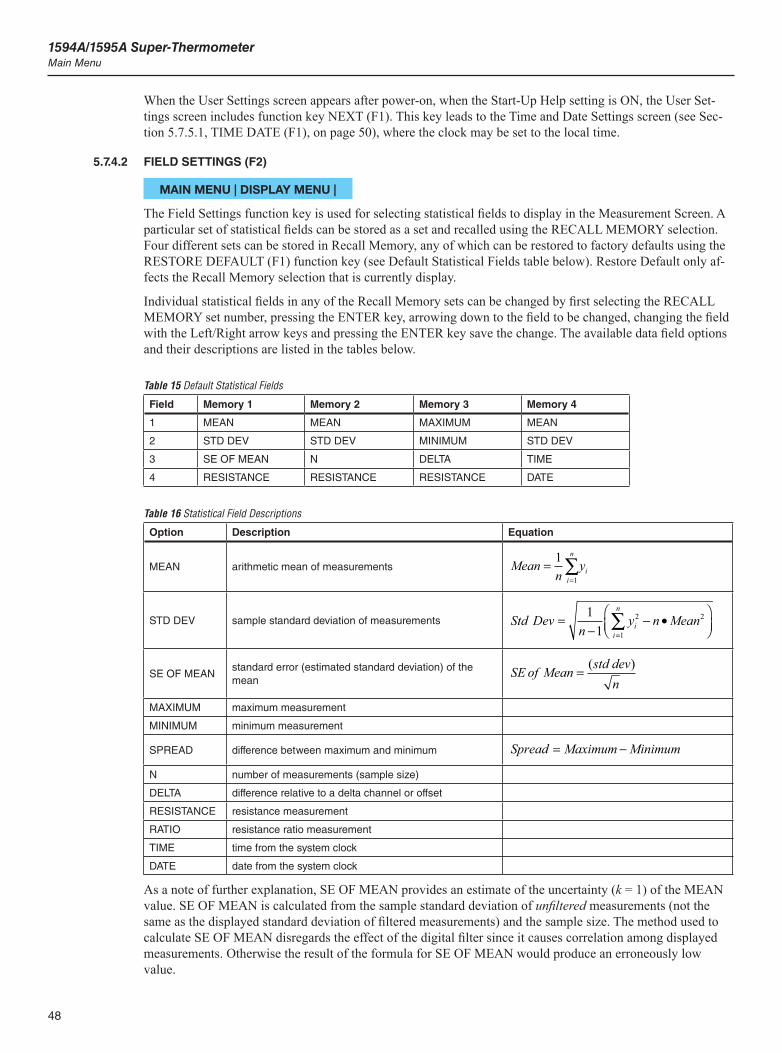
1594A/1595A Super-ThermometerMain Menu
48
When the User Settings screen appears after power-on, when the Start-Up Help setting is ON, the User Set-tings screen includes function key NEXT (F1). This key leads to the Time and Date Settings screen (see Sec-tion 5.7.5.1, TIME DATE (F1), on page 50), where the clock may be set to the local time.
5.7.4.2 FIELD SETTINGS (F2)
MAIN MENU | DISPLAY MENU |
The Field Settings function key is used for selecting statistical fields to display in the Measurement Screen. A particular set of statistical fields can be stored as a set and recalled using the RECALL MEMORY selection. Four different sets can be stored in Recall Memory, any of which can be restored to factory defaults using the RESTORE DEFAULT (F1) function key (see Default Statistical Fields table below). Restore Default only af-fects the Recall Memory selection that is currently display.
Individual statistical fields in any of the Recall Memory sets can be changed by first selecting the RECALL MEMORY set number, pressing the ENTER key, arrowing down to the field to be changed, changing the field with the Left/Right arrow keys and pressing the ENTER key save the change. The available data field options and their descriptions are listed in the tables below.
Table 15 Default Statistical Fields
Field Memory 1 Memory 2 Memory 3 Memory 4
1 MEAN MEAN MAXIMUM MEAN
2 STD DEV STD DEV MINIMUM STD DEV
3 SE OF MEAN N DELTA TIME
4 RESISTANCE RESISTANCE RESISTANCE DATE
Table 16 Statistical Field Descriptions
Option Description Equation
MEAN arithmetic mean of measurements Meann
yi
n
i==
∑11
STD DEV sample standard deviation of measurements Std Devn
y n Meanii
n
=−
− •
=
∑11
2
1
2
SE OF MEANstandard error (estimated standard deviation) of the mean
SE of Mean std devn
=( )
MAXIMUM maximum measurement
MINIMUM minimum measurement
SPREAD difference between maximum and minimum Spread Maximum Minimum= −
N number of measurements (sample size)
DELTA difference relative to a delta channel or offset
RESISTANCE resistance measurement
RATIO resistance ratio measurement
TIME time from the system clock
DATE date from the system clock
As a note of further explanation, SE OF MEAN provides an estimate of the uncertainty (k = 1) of the MEAN value. SE OF MEAN is calculated from the sample standard deviation of unfiltered measurements (not the same as the displayed standard deviation of filtered measurements) and the sample size. The method used to calculate SE OF MEAN disregards the effect of the digital filter since it causes correlation among displayed measurements. Otherwise the result of the formula for SE OF MEAN would produce an erroneously low value.

49
Menus and ScreensMain Menu
5.7.4.3 STATISTICS SETTINGS (F3)
MAIN MENU | DISPLAY MENU |
The Statistics Settings screen allows the user to set statistics related settings such as the statistics mode to be used.
STATISTICS MODE – determines the mode in which statistics are used. The options are LIMITED and UNLIMITED.
In Limited mode, statistics are calculated using a sliding window that is limited in width by the number of samples defined in the Sample Count setting. The oldest measurement leaves the sliding window buffer when a new measurement enters.
Unlimited mode allows the number of samples to grow indefinitely until the user resets the statistics or stops measurement.
SAMPLE COUNT - defines the number of samples on which the statistics are based. In LIMITED mode, this setting defines the width of the sliding window. A maximum of 100 can be selected.
DELTA MODE - determines whether the Delta statistics field is based on a measurement from a channel or an offset entered by the user. The options are CHANNEL or OFFSET.
DELTA OFFSET - sets the offset value used for calculating Delta. This setting applies when Delta Mode is set to OFFSET.
When the Delta Offset value is subtracted from a measurement, it assumes the same units as the measurement. The setting has a range of -1.0E06 to 1.0E06.
Tip: Delta Mode is useful for automatically subtracting an offset from a measurement such as the lead resistance offset used when making 3-wire measurements.
DELTA CHANNEL- specifies the channel to be used as the reference for the Delta calculation. This setting is applicable when Delta Mode is set to CHANNEL. Possible options are channels 1 through 4 when no scanner is attached. If a scanner is attached, channel 1 is not available but the scanner channels are.
5.7.4.4 GRAPH SETTINGS (F4)
MAIN MENU | DISPLAY MENU |
The Graph Settings function key opens a screen that contains settings for controlling how data graphs appear in the Measurement Screen in Show Graph mode. The configuration fields in the Graph Settings screen are as follows:
COMBINED GRAPH - determines if all enabled channels are plotted on the same graph or on separate graphs. ON plots all channels on the same graph.
TIME SPAN - configures the horizontal time scale or width of the graph window. The options are 5 min, 10 min, 15 min, 30 min, 1 hr, 2 hr, 4 hr, and 8 hr. The default is 10 min.
AUTOMATIC CENTERING - determines whether the center of the vertical axis is set automatically based on the data in the graph (ON) or if the center is fixed at the Vertical Center value (OFF). The default value is ON.
VERTICAL CENTER - sets the center of the vertical axis of the combined graph when Automatic Centering is ON. The setting has a range of -1.0E6 to 1.0E6. The default value is 0.0.
AUTOMATIC SCALING - determines whether the scale of the vertical axis is set automatically based on the data in the graph (ON) or if the scale is fixed at the Vertical Scale value (OFF). The default value is ON.
VERTICAL SPAN - sets the scale of the vertical axis of the combined graph when Automatic Scaling is OFF. The setting has a range of 1.0E-6 to 1.0E6. The default value is 0.1.

1594A/1595A Super-ThermometerMain Menu
50
TRACE - controls whether a measurement point is plotted with a line that connects to the previous point or as a separate dot. The options are LINE and DOT. The default value is DOT.
Important: When Time Span is large, multiple points may be combined and drawn as a vertical line to conserve memory.
5.7.4.5 TEMPERATURE UNIT (F5)
MAIN MENU | DISPLAY MENU |
The Temperature Unit screen allows the user to select the unit for displayed temperature measurements. The options are °C, K, and °F. °F will not be available if SI Unit Lock is set to ON in the Calibration Parameters screen of the Calibration menu (see Section 5.7.7.2, CALIBRATION (F5), on page 55). The default value is °C.
5.7.5 SYSTEM MENU (F5)
MAIN MENU |
Figure 15 System Menu Screen
The System Menu contains general system settings such as time and date, remote interface, password, and calibration.
The System Menu screen displays the following product information: Manufacturer, Model, Serial Number, Firmware Version, and Calibration Date.
The following are the System Menu function keys:
5.7.5.1 TIME DATE (F1)
MAIN MENU | SYSTEM MENU |
The Time and Date function key allows the user to enter the system Time and Date using the following fields:
TIME - time of the system clock. It is always in 24-hour format.
DATE - date of the system clock. It appears in the format determined by the Date Format setting (see Section 5.7.4.1, USER SETTINGS (F1), on page 47).
51
Menus and ScreensMain Menu
DAYLIGHT SAVING - determines whether the clock is automatically adjusted at the beginning and end of the Daylight Saving period. Options are OFF, NORTH AMERICA, and EUROPE. The default option is OFF.
5.7.5.2 REMOTE INTERFACE (F2)
MAIN MENU | SYSTEM MENU |
The Remote Interface screen contains the function keys used for configuring and monitoring the remote inter-face ports. For more information on the Remote Interface ports and a list of remote operation commands, see Section 8, Remote Operation, on page 65.
The following are the function keys located in the Remote Interface menu.
5.7.5.2.1 SERIAL (F1)
MAIN MENU | SYSTEM MENU | REMOTE INTERFACE |
The Serial function key is used to configure the RS-232 serial port with the following configuration fields:
BAUD RATE - baud rate setting of the serial port. It may be set to 1200, 2400, 4800, 9600, 19200, or 38400. The default setting is 9600.
LINEFEED - determines whether a linefeed character (ASCII code 10) is transmitted at the end of every message.
5.7.5.2.2 USB (F2)
MAIN MENU | SYSTEM MENU | REMOTE INTERFACE |
The USB function key displays the following configuration field:
PORT ENABLE – enables and disables the rear USB port for remote communications with a computer (The front USB port, used for an external USB memory device, is always enabled).
5.7.5.2.3 NETWORK (F3)
MAIN MENU | SYSTEM MENU | REMOTE INTERFACE |
The Network function key opens a screen allowing the user to configure the Network port settings.
The network port implements a 10/100 Base T Ethernet network interface. It supports the protocols TCP/IP, DHCP, and HTML. The port is disabled by default and must be enabled to be used. The user may select DHCP or specify a static network address.
The network port may be used for remote control of the Super-Thermometer by a PC and interface to network software such as Telnet or a COM port redirector driver. In this mode, the network port accepts a raw TCP connection on TCP port number 5025.
The network port also provides a simple HTML web page interface to the Super-Thermometer to allow remote monitoring via a web browser.
The following are the configuration fields:
HARDWARE MAC - shows the hardware MAC address of the network port. It cannot be changed.
DHCP ENABLE - determines whether the static IP address is used or is assigned dynamically by a server. The default option is ON (dynamic).
CAUTION: When DHCP is enabled, do not remove the Ethernet cable and turn the power off. The cable needs to remain plugged into the unit while cycling the power.
IP ADDRESS - specifies the network port’s IP address when DHCP is OFF, or shows the dynamically as-signed IP address when DHCP is set to ON.
GATEWAY - specifies the gateway server’s IP address to be used when DHCP is OFF.,
1594A/1595A Super-ThermometerMain Menu
52
SUBNET MASK - specifies the network’s subnet mask when DHCP is OFF. Gateway and Subnet Mask are not available when DHCP is set to ON.
HOST NAME - is a name that may be used to identify the Super-Thermometer on the network. It may consist of a combination of letters and digits, up to 16 characters in length. The first character must be a letter. Hyphen characters are allowed within the Host Name string. The default Host Name is “F159X-<serial number>”, where <serial number> is the unique serial number of the Super-Thermometer.
CONTROL ENABLE - determines whether remote interface commands are accepted via the network port. The options for this setting are OFF, ON, and QUERY ONLY. When the setting is OFF, the Super-Thermom-eter will not accept or respond to any commands received from the network port. When the option is ON all commands are allowed, though some may be password protected. The QUERY ONLY option allows data and settings to be read but not changed. The default is ON.
Important: When Control Enable is either OFF or QUERY ONLY, the web page will not be fully functional.
5.7.5.2.4 IEEE-488 (F4)
MAIN MENU | SYSTEM MENU | REMOTE INTERFACE |
The IEEE-488 function key opens the IEEE-488 configuration screen with the following configuration fields:
PORT ENABLE - determines whether the IEEE-488 port is enabled (ON). When the port is disabled, no communications can occur. The default option is OFF.
ADDRESS - is the IEEE-488 address assigned to the Super-Thermometer. It must be different than all other equipment on the IEEE-488 bus. The address may be set to any number between 1 and 30 inclusive. The default setting is 22.
TERMINATION - determines whether a carriage return character (ASCII code 13) or linefeed character (ASCII code 10) terminates a response. The default option is LINEFEED. An IEEE-488 EOI message also ac-companies the final character of every transmission.
The IEEE-488 port accepts either, or any combination of, a linefeed, carriage return, or EOI as a terminator.
The CLEAR INTERFACE (F1) function key is used to clear the input and output buffers and reset the IEEE-488 interface, just as if the IFC or SDC control message was received.
5.7.5.2.5 ERRORS (F5)
MAIN MENU | SYSTEM MENU | REMOTE INTERFACE |
The Errors screen allows the user to view errors stored in the remote interface error queue. They can also be read using the remot command “SYST:ERR?” (see Section 8, Remote Operation, on page 65)
The screen shows a list of all the errors, with the earliest error at the top. Errors are identified with their queue position number, error code, and message string. The error queue can hold up to ten errors. If the queue over-flows with errors, the last error is replaced with a “Queue overflow” error message.
The Errors screen contains the CLEAR ERRORS (F1) function key that, when pressed, clears all errors from the error queue.
5.7.5.3 CONFIG (F3)
MAIN MENU | SYSTEM MENU |
The Configuration screen provides the means for storing the instrument configuration and recalling it later. Several different configurations may be stored to allow quick and easy setup from user to user or from one ap-plication to another. The following function keys are located in this screen.

53
Menus and ScreensMain Menu
5.7.5.3.1 STORE CONFIG (F1)
MAIN MENU | SYSTEM MENU | CONFIG |
The Store Configuration function allows the user to store settings to a configuration file in either internal non-volatile memory or a USB flash memory device. The following settings are stored:
The probe definition assigned to each channel Enable state of each channel Channel settings, including the reference resistor selections Resistor definition assigned to each reference resistor input Scan settings Timing settings Digital filter settings User Settings Statistics fields settings Statistics settings Graph settings Temperature unit Recording settings
The Store Configuration function does not store probe definitions, resistor definitions, time and date, remote interface port settings, password settings, calibration parameters, or recorded data.
MEMORY DEVICE - specifies to which memory device the configuration is stored. The options are USB and INTERNAL. The default option is INTERNAL. Up to 50 configuration files may be stored internally. The number of files stored on a USB device is limited only by the storage space available.
FILE NAME - specifies the name of the configuration file. It is edited or entered by first pressing the ENTER key, which opens the Alpha-Numeric Interface. The file name may have up to 24 characters. The user must press the SAVE (F3) function key when finished. If the file does not exist, it is created. If it already exists, the contents of the file are replaced. The file name extension “.txt” is automatically added to the file name when the file is created. Once the memory device and file name are selected, the user presses the STORE (F1) func-tion key to proceed.
USB configuration files are written to a folder named “\159x\config” on the USB memory device and have the extension “.txt”. When writing the file to a USB memory device, a formatted USB memory device must be inserted into the USB socket on the front panel.
5.7.6 RECALL CONFIG (F2)
MAIN MENU | SYSTEM MENU | CONFIG |
The Recall Configuration screen displays the configuration files that have been saved to memory. The location of the file(s) must be selected using the MEMORY DEVICE field. The options are INTERNAL and USB.
Once the memory location is selected, pressing ENTER or the CONTINUE (F1) function key will open the list of configuration files. Using the Up/Down arrow keys, the configuration is selected. Pressing ENTER or the CONTINUE (F1) function key opens the file. The user is prompted to continue before the changes are implemented.
The Recall Configuration function does not affect probe definitions, resistor definitions, time and date, remote interface port settings, password settings, calibration parameters, or recorded data. If an assigned probe defini-tion no longer exists in the Probe Library when a configuration is recalled, the channel is set to UNDEFINED. Likewise, a reference resistor input will be set to VARIABLE if the resistor ID is not found in the Resistor Library.
1594A/1595A Super-ThermometerMain Menu
54
5.7.7 DELETE CONFIG (F3)
MAIN MENU | SYSTEM MENU | CONFIG |
The Delete Configuration function may be used to delete a configuration file in internal memory. The screen shows a list of configuration files found in the internal non-volatile memory. The user presses the Up/Down arrow keys to select one of the configuration files, then CONTINUE (F1) or ENTER to delete the file. The use must confirm the action before the configuration is deleted.
5.7.7.3.1 RESTORE DEFAULT (F4)
MAIN MENU | SYSTEM MENU | CONFIG |
The Restore Default function may be used to restore settings to factory default values. The user must press the YES (F4) function key to run the restore function. The NO (F5) function key or EXIT key will exit the screen without restoring default settings. The settings that are affected are listed in the Store Configuration section.
5.7.7.3.2 UPDATE FIRMWARE (F5)
MAIN MENU | SYSTEM MENU | CONFIG |
The Update Firmware function key may be used to update the internal software to a newer version when avail-able from the manufacturer.
The Update Firmware function is always password protected. The user will be prompted to enter the correct password to proceed.
A message appears instructing the user to plug in a USB memory device that contains the firmware update file.
A confirmation message screen appears prompting the user to press YES to proceed. While the firmware update file is being read from the USB and loaded into the system, the power must not be switched off. If the power is switched off during the firmware update process, the instrument may no longer operate and will need to be returned to the factory for servicing.
Caution: Do not switch off the power while the firmware is being updated.
Once the firmware update process is completed, a message indicates that the firmware has been successfully updated. The user must then switch the power off and then on to restart and operate with the new firmware.
5.7.7.1 PASSWORD (F4)
MAIN MENU | SYSTEM MENU |
In the Password screen the user may view and change password settings. The Password screen is always password protected (the default is 1234). The user will be prompted to enter the correct password to access the screen. Password protection can be enabled for probe configurations, resistor definitions, certain measure func-tions, and system time/date settings. See the following configuration field descriptions for more detail.
PASSWORD - a four-digit number that must be entered by the user in order to change settings in any pass-word protected screen. The user may change the password to any four-digit number. The default is 1234.
Important: The user must be sure to remember the password or record the password in a safe location. If the password is forgotten or lost, the instrument must be returned to the factory to have the password reset.
PROBE PROTECTION - enables or disables protection of probe definition related screens. This setting is useful for ensuring that probe definitions in the Probe Library do not get inadvertently changed. The default is OFF.
55
Menus and ScreensMain Menu
RESISTOR PROTECTION - enables or disables protection of resistor definition related screens. This setting is useful for ensuring that resistor definitions in the Resistor Library do not get inadvertently changed. The default is OFF.
MEASURE PROTECTION- enables or disables protection of measurement setting screens. This setting is used for ensuring that timing and digital filter settings do not get inadvertently changed, possibly resulting in noisy or less accurate measurements. The default is OFF.
TIME/DATE PROTECTION- enables or disables protection of the Time and Date setting screen. The de-fault is OFF.
Some screens are always protected and have no associated protection setting. An example is the Calibration Parameters screen, which always requires the correct password before any of the settings can be changed.
5.7.7.2 CALIBRATION (F5)
MAIN MENU | SYSTEM MENU |
The Calibration menu contains functions and settings for testing and maintaining proper performance of the Super-Thermometer. Refer to Section 9, Calibration, on page 103 for test and calibration instructions.
The following are the Calibration Menu function keys.
5.7.7.2.1 SYSTEM TEST (F1)
MAIN MENU | SYSTEM MENU | CALIBRATION |
The System Test function key is used to perform a system self-test. This tests various components of the Super-Thermometer and reports the results. If System Test indicates failures, contact the nearest Fluke Autho-rized Service Center. See Section 9.2, SYSTEM TEST (F1), on page 103 for more information.
5.7.7.2.2 CURRENT TEST (F2)
MAIN MENU | SYSTEM MENU | CALIBRATION |
The Current Test function allows the user to test the accuracy of the sensing current on the front panel input channels.
See Section 9.3, CURRENT TEST (F2), on page 103 for more information on how to perform a current test.
5.7.7.2.3 RATIO CALIBRATION (F3)
MAIN MENU | SYSTEM MENU | CALIBRATION |
The Ratio Self-Calibration function allows the user to perform a ratio linearity check or calibration. A check allows the user to verify ratio accuracy without making changes to ratio parameters. Calibration measures the Super-Thermometer ratios and makes adjustments to the ratio parameters. A check should always be per-formed after running the ratio self-calibration function to verify that alignment was successful. See Section 9.4, RATIO CALIBRATION (F3), on page 104 for more information.
5.7.7.2.4 RESISTANCE CALIBRATION (F4)
MAIN MENU | SYSTEM MENU | CALIBRATION |
The Resistance Calibration function allows the user to test and calibrate the internal reference resistors. See Section 9.5, RESISTANCE CALIBRATION (F4), on page 106 for more information.
5.7.7.2.5 CALIBRATION PARAMETERS (F5)
MAIN MENU | SYSTEM MENU | CALIBRATION |
Important: Calibration parameters should not be changed except as part of the Super-Thermometer calibration procedure performed by a qualified service technician.
1594A/1595A Super-ThermometerMain Menu
56
In the Calibration Parameters screen the user may view and change measurement calibration settings. The calibration parameters can be viewed with no password but a password is required to make changes.
Calibration parameters include calibrated values for each of the internal resistors and the linearity coefficients for the resistance ratio measurements. Since the accuracy of the Super-Thermometer depends on these values, they must be accurate. Refer to Section 9.4.2, ADJUST PARAMETERS (F2), on page 106 for instructions needed to adjust the calibration parameters.
Apart from the calibration parameters, the Calibration Parameters screen also includes the following configu-ration fields:
CALIBRATION DATE- used to record the date the Super-Thermometer is calibrated.
SI UNIT LOCK- enables or disables °F as an allowed temperature unit option. When this is set to ON, tem-peratures may be displayed in units of °C and K only, and °F will not be available as an option for the Unit setting (see Section 5.7.4.5, TEMPERATURE UNIT (F5), on page 50).
57
Getting StartedUser Settings Screen
6 Getting Started
6.1 Powering on the Super-Thermometer
CAUTION: Before powering the Super-Thermometer on, ensure that the line voltage selection is set properly. Refer to Section 3.3, Line Voltage and Fuses, on page 15 for instructions.
Power the Super-Thermometer on by setting the power switch located on the back panel to the On position. After power is on, pressing the Power Standby switch on the front panel puts the system into hibernation, leav-ing key components such as the resistor oven powered on.
The first time the unit is powered on, the User Settings screen will be displayed after startup. Later in the sec-tion it will be explained how this feature is turned off so the Measurement screen is displayed when the unit is powered on.
6.2 User Settings ScreenThe User Settings screen allows the user to configure system settings such as language, temperature measure-ment resolution, screen saver settings and alarms. As mentioned previously, the User Settings screen is the first displayed upon the first power-up if the Start-Up Help setting is enabled. This setting can be turned off by the user after the user settings have been configured.
The following fields are displayed in the User Settings screen:
LANGUAGE- sets the language in which the menus and screens are displayed. The options are ENGLISH, CHINESE, JAPANESE,SPANISH, GERMAN, FRENCH, and RUSSIAN. ENGLISH is the default option.
DATE FORMAT- sets the format used to display dates on the screen. Available options are YYYY-MM-DD, MM-DD-YYYY, and DD/MM/YYYY. The default option is YYYY-MM-DD. This setting has no effect on communications commands and responses, recorded data, or library files.
DECIMAL FORMAT- sets the decimal character used in decimal numbers on the display. Available options are period (.) and comma (,). The default option is (.). This setting has no effect on communications commands and responses, recorded data, or library files.
TEMPERATURE RESOLUTION- sets the desired number of decimal places that appear in displayed tem-perature measurements. Available options are 0.1 through 0.000001. The default option is 0.00001. The actual number of decimal places of displayed temperatures may be reduced for large numbers. This setting has no effect on communications commands and responses, recorded data, or library files. The resolution of displayed resistances and resistance ratios is fixed at the maximum practical resolution.
SCREEN SAVER ENABLE- enables or disables the screen saver. If Screen Saver Enable is OFF, the display will remain on indefinitely. Enabling the screen saver saves power and extends the lifetime of the display. The default option is OFF.
SCREEN SAVER DELAY- sets the screen saver delay time. Available options are 5 min, 10 min, 15 min, 30 min, 45 min, 1 hr, and 2 hr. The default option is 1 hr.
DISPLAY BRIGHTNESS- sets the brightness of the display backlight. Available options are 50 %, 60 %, 70 %, 80 %, 90 %, and 100 %. The default option is 100 %. Reducing the display brightness saves power and extends the lifetime of the display.
ITS-90 SUBRANGE ALERT- enables (ON) or disables (OFF) the warning message that appears at the bot-tom of the Measurement Screen when a probe’s measured temperature exceeds its ITS-90 subrange by more than 10°C. The default option is ON.
Rs DUE ALERT- enables (ON) or disables (OFF) the warning message that appears at the bottom of the Mea-surement screen when the due date of a resistor in the Resistor Library has expired. The default option is OFF.
ALERT BEEP- enables (ON) or disables (OFF) the audio indication that accompanies warning messages. The default option is ON.
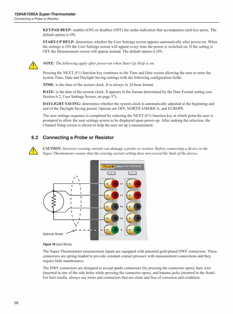
1594A/1595A Super-ThermometerConnecting a Probe or Resistor
58
KEYPAD BEEP- enables (ON) or disables (OFF) the audio indication that accompanies each key-press. The default option is ON.
START-UP HELP- determines whether the User Settings screen appears automatically after power-on. When the settings is ON the User Settings screen will appear every time the power is switched on. If the setting is OFF the Measurement screen will appear instead. The default option is ON.
NOTE: The following apply after power-on when Start-Up Help is on:
Pressing the NEXT (F1) function key continues to the Time and Date screen allowing the user to enter the system Time, Date and Daylight Saving settings with the following configuration fields:
TIME- is the time of the system clock. It is always in 24-hour format.
DATE- is the date of the system clock. It appears in the format determined by the Date Format setting (see Section 6.2, User Settings Screen, on page 57).
DAYLIGHT SAVING- determines whether the system clock is automatically adjusted at the beginning and end of the Daylight Saving period. Options are OFF, NORTH AMERICA, and EUROPE.
The user settings sequence is completed by selecting the NEXT (F1) function key at which point the user is prompted to allow the user settings screen to be displayed upon power-up. After making the selection, the Channel Setup screen is shown to help the user set up a measurement.
6.3 Connecting a Probe or Resistor
CAUTION: Incorrect sensing current can damage a probe or resistor. Before connecting a device to the Super-Thermometer ensure that the sensing current setting does not exceed the limit of the device.
Figure 16 Input Wiring
The Super-Thermometer measurement inputs are equipped with patented gold-plated DWF connectors. These connectors are spring-loaded to provide constant contact pressure with measurement connections and they require little maintenance.
The DWF connectors are designed to accept spade connectors (by pressing the connector open), bare wire (inserted in one of the side holes while pressing the connector open), and banana jacks (inserted in the front). For best results, always use wires and connectors that are clean and free of corrosion and oxidation.
59
Getting StartedConnecting a Probe or Resistor
The DWF connectors are labeled with C1, C2 (current connections) and P1, P2 (measurement potential con-nections). The guard connector is labeled with a “G” and is used for connecting to a probe or resistor guard or shield. The guard connection may help reduce measurement noise.
Connect a probe or resistor, as specified by the device’s manufacturer, to any one of the four measurement channels located on the front panel. To prevent the possibility of applying too much current, suspend measure-ment sampling and configure the channel before making the connection.

61
Making MeasurementsMeasuring a Temperature Probe
7 Making Measurements
7.1 IntroductionThe Super-Thermometer has been designed to allow quick and easy measurement setup while providing flex-ible measurement options. The purpose of this section is to guide the user through the configuration of the Super-Thermometer for typical measurements.
7.2 Measuring a Temperature ProbeThe following instructions apply to the setup of both PRTs and thermistors for temperature measurement.
1. Press and hold the EXIT key to go to the Measurement screen.
2. If necessary, suspend measurement by pressing the STOP MEASUREMENT (F1) function key.
3. Using the instructions in the Getting Started section, connect a temperature probe to one of the measurement input channels.
4. Press the SETUP key to open the Channel Setup screen. Use the Up/Down arrow keys to highlight the channel to which the probe is connected. Scanner channels, if available, are identified with a S1 (scanner 1) or S2 (scanner 2) prefix added to the channel number.
5. Once the channel is highlighted, use the following steps to assign a probe definition to the selected channel.
a. Select the ASSIGN PROBE (F1) function key to open the Probe Library.
b. Scroll through the list of probe definitions using the Up/Down arrow keys to locate the probe’s definition. If the probe definition has not been previously entered, select ADD PROBE (F1) to begin the process of creating a probe definition (see Section 5.7.2, PROBE MENU (F2), on page 34 for more information).
c. When the probe definition is selected, press the ENTER key to assign the selected probe definition to the channel and return to the Channel Setup menu.
6. Select the CHANNEL SETTINGS (F2) function key to configure the measurement channel using the following steps:
a. Select the desired reference resistor (Rs) to be used for the measurement by pressing the Left/Right arrow keys and pressing ENTER to confirm the selection. Use “Table 17 Recommended Reference Resistors and Sensing Current” on page 62 as a guide for the selection.
b. Enter the correct sensing current using Table 17 on page 62 or the probe manufacturer’s instructions as a guide.
c. Determine whether standby current (see Channel Setup section) is to be On or Off.
d. Select the desired measurement calculation. The options are RESISTANCE (to output the probe’s resistance only), RATIO (to output the ratio of the probe’s resistance versus the reference resistor), and TEMPERATURE (only if calibration coefficients were entered in the probe definition).
e. Press the EXIT key to move back to the Channel Setup screen.
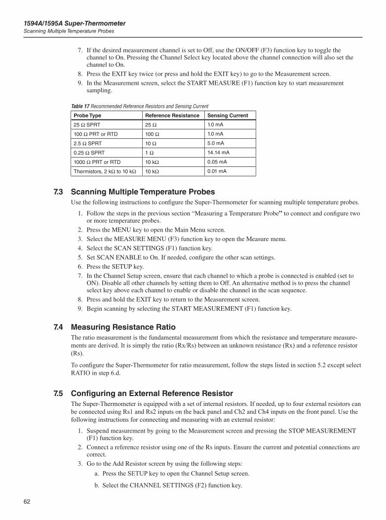
1594A/1595A Super-ThermometerScanning Multiple Temperature Probes
62
7. If the desired measurement channel is set to Off, use the ON/OFF (F3) function key to toggle the channel to On. Pressing the Channel Select key located above the channel connection will also set the channel to On.
8. Press the EXIT key twice (or press and hold the EXIT key) to go to the Measurement screen.
9. In the Measurement screen, select the START MEASURE (F1) function key to start measurement sampling.
Table 17 Recommended Reference Resistors and Sensing Current
Probe Type Reference Resistance Sensing Current
25 W SPRT 25 W 1.0 mA
100 W PRT or RTD 100 W 1.0 mA
2.5 W SPRT 10 W 5.0 mA
0.25 W SPRT 1 W 14.14 mA
1000 W PRT or RTD 10 kW 0.05 mA
Thermistors, 2 kW to 10 kW 10 kW 0.01 mA
7.3 Scanning Multiple Temperature ProbesUse the following instructions to configure the Super-Thermometer for scanning multiple temperature probes.
1. Follow the steps in the previous section “Measuring a Temperature Probe” to connect and configure two or more temperature probes.
2. Press the MENU key to open the Main Menu screen.
3. Select the MEASURE MENU (F3) function key to open the Measure menu.
4. Select the SCAN SETTINGS (F1) function key.
5. Set SCAN ENABLE to On. If needed, configure the other scan settings.
6. Press the SETUP key.
7. In the Channel Setup screen, ensure that each channel to which a probe is connected is enabled (set to ON). Disable all other channels by setting them to Off. An alternative method is to press the channel select key above each channel to enable or disable the channel in the scan sequence.
8. Press and hold the EXIT key to return to the Measurement screen.
9. Begin scanning by selecting the START MEASUREMENT (F1) function key.
7.4 Measuring Resistance RatioThe ratio measurement is the fundamental measurement from which the resistance and temperature measure-ments are derived. It is simply the ratio (Rx/Rs) between an unknown resistance (Rx) and a reference resistor (Rs).
To configure the Super-Thermometer for ratio measurement, follow the steps listed in section 5.2 except select RATIO in step 6.d.
7.5 Configuring an External Reference ResistorThe Super-Thermometer is equipped with a set of internal resistors. If needed, up to four external resistors can be connected using Rs1 and Rs2 inputs on the back panel and Ch2 and Ch4 inputs on the front panel. Use the following instructions for connecting and measuring with an external resistor:
1. Suspend measurement by going to the Measurement screen and pressing the STOP MEASUREMENT (F1) function key.
2. Connect a reference resistor using one of the Rs inputs. Ensure the current and potential connections are correct.
3. Go to the Add Resistor screen by using the following steps:
a. Press the SETUP key to open the Channel Setup screen.
b. Select the CHANNEL SETTINGS (F2) function key.
63
Making MeasurementsMaking A Zero-Power Measurement
c. Select the SETUP RS (F1) function key.
d. Select the DEFINE RESISTOR (F2) function key.
e. Select the ADD RESISTOR (F1) function key.
4. Enter a unique ID in the ID field. Pressing the ENTER key will open the Alpha-Numeric Interface for text entry.
5. Enter the resistance value of the resistor in the RESISTANCE VALUE field.
Caution: The Resistance Value field is used in measurement for the calculation of the Rx resistance. Entering this value incorrectly will cause measurement error.
6. Set the maximum measurement current allowed for the reference resistor.
7. If necessary, enter the calibration date and due date for the external reference resistor. The Super-Thermometer will use the due date to warn the user when the resistor is due for calibration.
8. Select the SAVE (F1) function key to save the definition.
9. Press the EXIT key to go up one menu to the Set Up Rs screen. Use the Up/Down arrow keys to highlight the Rs input to which the external resistor is connected.
10. Select the ASSIGN RESISTOR (F1) function key to open a list of defined reference resistors. Use the Up/Down arrow keys to highlight the resistor’s definition. Press the ENTER key to assign the resistor to the selected Rs input.
11. Now, when selecting the reference resistor in Section 7.2, Measuring a Temperature Probe, on page 61, step 6.a, the newly entered external resistor will appear as an option.
7.6 Making A Zero-Power MeasurementA temperature probe self-heats when measurement current is passed through its sensing element. Typically self-heating will cause measurement error. The Super-Thermometer Zero-Power function allows the user to measure how much a probe self-heats. It is also able to automatically measure a probe at zero-power. Use the following instructions for performing a zero-power measurement:
1. Press and hold the EXIT key to go to the Measurement screen.
2. If necessary, suspend measurement by pressing the STOP MEASUREMENT (F1) function key.
3. Using the instructions in the Getting Started section, connect a temperature probe to one of the measurement input channels.
4. Configure the probe definition ensuring that the MAXIMUM CURRENT field is set to a value equal to or greater than 1.4142 times the nominal current value.
5. Open the ZERO-POWER MEASUREMENT screen by pressing the MENU key, then the MEASURE MENU (F3) function key, followed by the ZERO-POWER MEASUREMENT (F5) function key.
6. In the Zero-Power Measurement screen, set CHANNEL to the channel where the probe is connected.
7. Set the SETTLE TIME field to a sufficient time period to allow the probe to self-heat and stabilize after current is applied. For most probes 1 minute is sufficient.
8. Set the MEASURE TIME field to a time span that allows a sufficient number of samples to be taken. For example, with a 2-second sample period and 2-second Display Interval, a 1-minute Measurement Time will yield 30 samples.
9. If necessary, use REPEAT NOMINAL to set the Super-Thermometer to repeat nominal current measurement after the 1.4142X step is complete. The difference between the beginning and ending nominal current values will indicate if the probe was sufficiently equilibrated during zero-power measurement.
10. When ready, press the START (F1) function key to start the zero-power sequence of measurements.
11. When the measurements are complete, the results are displayed on the screen.

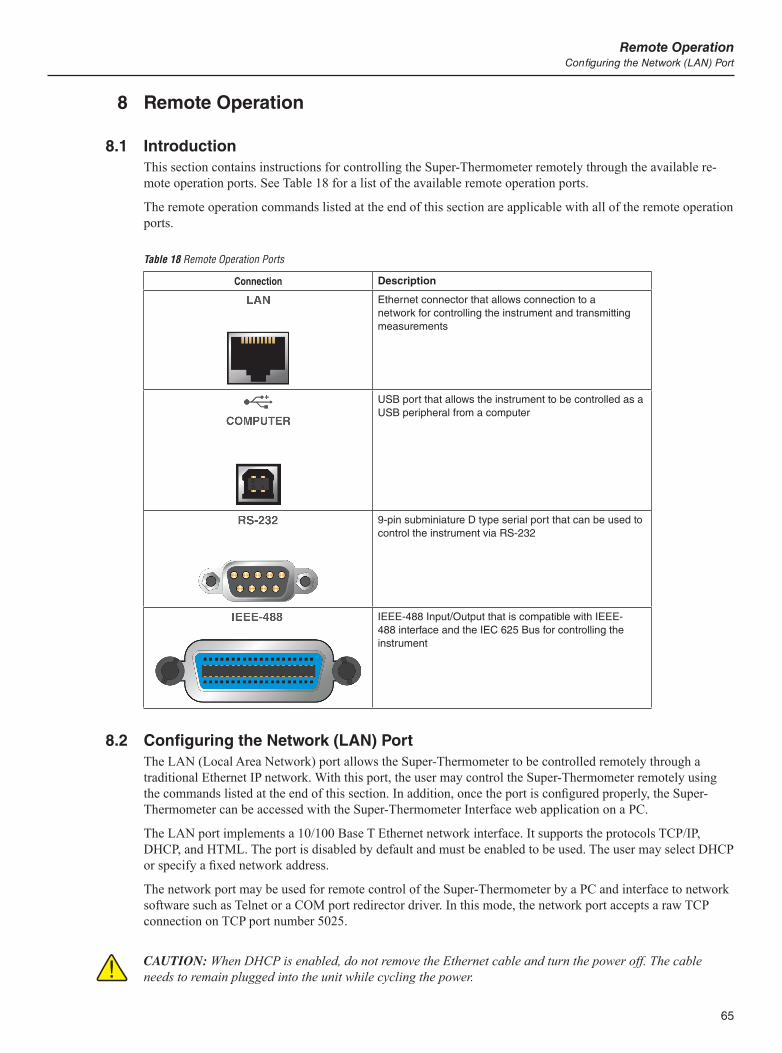
65
Remote OperationConfiguring the Network (LAN) Port
8 Remote Operation
8.1 IntroductionThis section contains instructions for controlling the Super-Thermometer remotely through the available re-mote operation ports. See Table 18 for a list of the available remote operation ports.
The remote operation commands listed at the end of this section are applicable with all of the remote operation ports.
Table 18 Remote Operation Ports
Connection Description
Ethernet connector that allows connection to a network for controlling the instrument and transmitting measurements
USB port that allows the instrument to be controlled as a USB peripheral from a computer
9-pin subminiature D type serial port that can be used to control the instrument via RS-232
IEEE-488 Input/Output that is compatible with IEEE-488 interface and the IEC 625 Bus for controlling the instrument
8.2 Configuring the Network (LAN) PortThe LAN (Local Area Network) port allows the Super-Thermometer to be controlled remotely through a traditional Ethernet IP network. With this port, the user may control the Super-Thermometer remotely using the commands listed at the end of this section. In addition, once the port is configured properly, the Super-Thermometer can be accessed with the Super-Thermometer Interface web application on a PC.
The LAN port implements a 10/100 Base T Ethernet network interface. It supports the protocols TCP/IP, DHCP, and HTML. The port is disabled by default and must be enabled to be used. The user may select DHCP or specify a fixed network address.
The network port may be used for remote control of the Super-Thermometer by a PC and interface to network software such as Telnet or a COM port redirector driver. In this mode, the network port accepts a raw TCP connection on TCP port number 5025.
CAUTION: When DHCP is enabled, do not remove the Ethernet cable and turn the power off. The cable needs to remain plugged into the unit while cycling the power.
1594A/1595A Super-ThermometerConfiguring the Network (LAN) Port
66
Configuring the LAN port is accomplished through the Remote Interface section of the System menu. The LAN configuration parameters are HARDWARE MAC, DHCP ENABLE, IP ADDRESS, GATEWAY, SUB-NET MASK, HOST NAME, and CONTROL ENABLE.
To configure the LAN port settings:
1. Press the MENU key.
2. Select the SYSTEM MENU (F5) function key
3. Select the REMOTE INTERFACE (F2) function key
4. Select the NETWORK (F3) function key
5. Use the following instructions to configure each setting.
Note: When addressing some LAN addresses, computers will often interpret 0’s in the IP address as OCTAL values. As an example, if an IP address is entered into the Super-Thermometer as 129.196.017.023 and then an attempt to establish communication to the instrument, the IP address of 129.196.17.23 should be used. Attempting to establish a connection to 120.196.017.023 may result in a connection request to 129.196.15.19.
Important: When changing LAN settings, leave the Super-Thermometer connected to the network and cycle the power to activate any changes made.
8.2.1 Hardware Mac Address
HARDWARE MAC is the address of the network port. It is set at the factory and cannot be changed.
8.2.2 Selecting Dynamic Host Configuration Protocol (DHCP)
Dynamic Host Configuration Protocol (DHCP) is a client-server protocol that eliminates having to manually set permanent/static IP addresses. The DHCP server provides configuration parameters (dynamic IP address, subnet mask, and default gateway IP addresses) which are required for a client to participate in an IP network,
Using DHCP is the easiest way to configure the Super-Thermometer for remote operation in a network. DHCP is enabled by default from the factory. When connected to a network, and the LAN port is enabled, the Super-Thermometer will try and retrieve the parameters from a DHCP server that are necessary for communication. If the parameters can’t be obtained, communication will not work.
Important: Before enabling or disabling DHCP, ensure the Super-Thermometer is connected to the network by plugging the network cable into the LAN port on the Super-Thermometer. Always cycle the power after making changes to DHCP.
To disable or enable DHCP, in the NETWORK screen, arrow down to DHCP ENABLE and use the Left/Right arrow keys to select ON (enable) or OFF (disable).
8.2.3 Setting a Static Internet Protocol (IP) Address
An internet (IP) address is required for all internet and TCP/IP communications. If DHCP is enabled, the Su-per-Thermometer will use the dynamic address supplied by the DHCP server. However, if DHCP is disabled, the configured static IP address will be used.
The Super-Thermometer comes from the factory with IP address set to 0.0.0.0.
Note: If the Super-Thermometer will be used on a corporate network and DHCP is not used, contact the network administrator for a static IP address to be used exclusively by the Super-Thermometer. DHCP must be disabled to use a static IP address.
To enter a static IP address, use the following steps:
67
Remote OperationConfiguring the Network (LAN) Port
1. In the NETWORK screen, use the Up/Down arrow keys to select DHCP ENABLE.
2. IF DHCP is set to ON, use the Left/Right arrow keys to select OFF. Press the ENTER key to save the change.
3. Arrow down to IP ADDRESS and enter the desired static IP address using the front panel keys. Press the ENTER key to save the IP address.
4. Cycle the unit’s power to allow the new address to take effect.
8.2.4 Setting the LAN Gateway Address
If communication to the Super-Thermometer passes through a router or gateway, and DHCP is disabled, the subnet mask and gateway address on both the host computer and the Super-Thermometer must be set. Get the correct subnet mask and gateway address from the network administrator.
The gateway address is the IP address of a gateway (router) attached to the same network as the Super-Ther-mometer. When the instrument detects that a host computer is not on the same network (using the network number), the data is sent through the gateway to reach the host computer.
The gateway address is a 32-bit number. This number is represented as four, 3-digit numbers. The default subnet mask address set from the factory is 0.0.0.0.
To change gateway address, use the following steps:
Note: Gateway address is not available if DHCP is enabled. Disable DHCP before entering the gateway address.
1. In the NETWORK screen, use the Up/Down arrow keys to select GATEWAY.
2. Use the front panel numeric keys to enter the gateway address. Press the ENTER key to save the address.
3. Cycle the unit’s power to allow the new address to take effect.
8.2.5 Setting the LAN Subnet Mask
If communication to the Super-Thermometer passes through a router or gateway, and DHCP is disabled, the subnet mask and default gateway address on both the host computer and the Super-Thermometer must be set. Get the correct subnet mask and gateway address from the network administrator.
The subnet mask is a 32-bit number. This number is represented as four, 3-digit numbers. The default subnet mask address set from the factory is 255.255.255.0.
To change subnet mask address, use the following steps:
Note: Subnet mask address is not available if DHCP is enabled. Disable DHCP before entering the subnet mask address.
1. In the NETWORK screen, use the Up/Down arrow keys to select SUBNET MASK.
2. Use the front panel numeric keys to enter the subnet mask address. Press the ENTER key to save the address.
3. Cycle the unit’s power to allow the new address to take effect.
8.2.6 Setting the Host Name
The Host Name is the host portion of the domain name, which is translated into an IP address. The de-fault host name is “F159X-<serial number>”, where <serial number> is the unique serial number of the Super-Thermometer.
To change the Host Name, use the following steps:
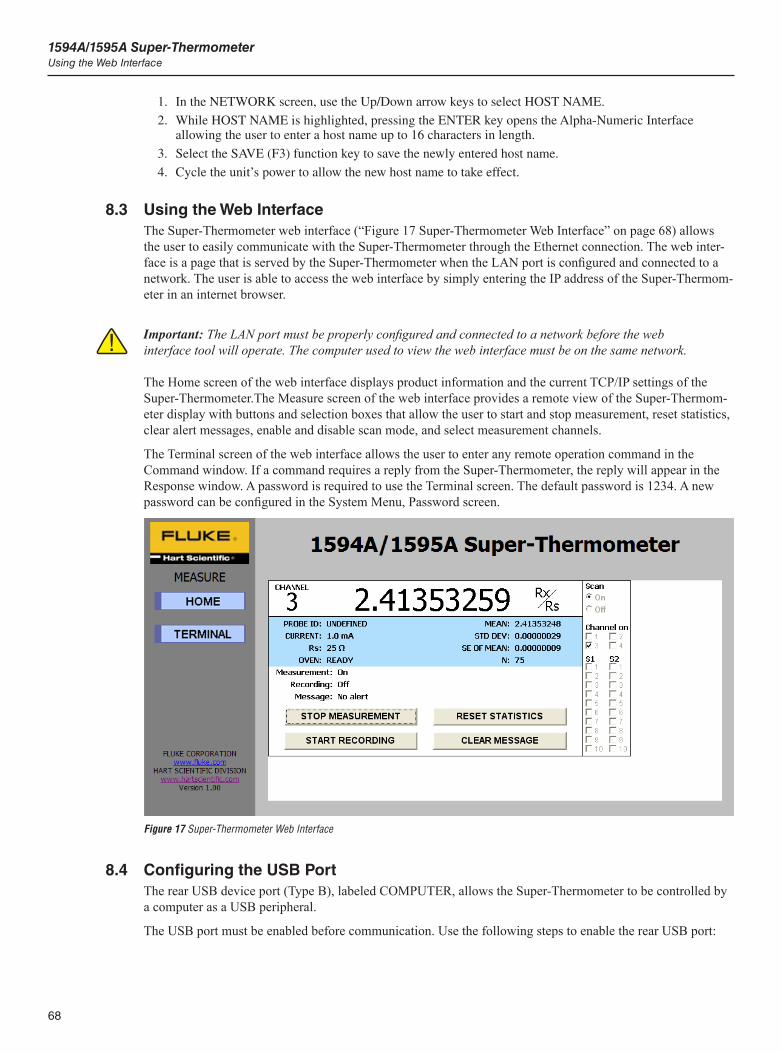
1594A/1595A Super-ThermometerUsing the Web Interface
68
1. In the NETWORK screen, use the Up/Down arrow keys to select HOST NAME.
2. While HOST NAME is highlighted, pressing the ENTER key opens the Alpha-Numeric Interface allowing the user to enter a host name up to 16 characters in length.
3. Select the SAVE (F3) function key to save the newly entered host name.
4. Cycle the unit’s power to allow the new host name to take effect.
8.3 Using the Web InterfaceThe Super-Thermometer web interface (“Figure 17 Super-Thermometer Web Interface” on page 68) allows the user to easily communicate with the Super-Thermometer through the Ethernet connection. The web inter-face is a page that is served by the Super-Thermometer when the LAN port is configured and connected to a network. The user is able to access the web interface by simply entering the IP address of the Super-Thermom-eter in an internet browser.
Important: The LAN port must be properly configured and connected to a network before the web interface tool will operate. The computer used to view the web interface must be on the same network.
The Home screen of the web interface displays product information and the current TCP/IP settings of the Super-Thermometer.The Measure screen of the web interface provides a remote view of the Super-Thermom-eter display with buttons and selection boxes that allow the user to start and stop measurement, reset statistics, clear alert messages, enable and disable scan mode, and select measurement channels.
The Terminal screen of the web interface allows the user to enter any remote operation command in the Command window. If a command requires a reply from the Super-Thermometer, the reply will appear in the Response window. A password is required to use the Terminal screen. The default password is 1234. A new password can be configured in the System Menu, Password screen.
Figure 17 Super-Thermometer Web Interface
8.4 Configuring the USB PortThe rear USB device port (Type B), labeled COMPUTER, allows the Super-Thermometer to be controlled by a computer as a USB peripheral.
The USB port must be enabled before communication. Use the following steps to enable the rear USB port:
69
Remote OperationConfiguring the IEEE-488 Port
1. Press the MENU key.
2. Select the SYSTEM MENU (F5) function key
3. Select the REMOTE INTERFACE (F2) function key
4. Select the USB (F2) function key
5. Use the Left/Right arrow keys to change PORT ENABLE to ON (enable).
Before plugging the USB communication cable from the Super-Thermometer into a computer, make sure the computer is connected to the internet to allow the USB driver to download and install in the computer automatically.
If an internet connection is not available, the computer will detect the Super-Thermometer as an unknown USB device and will prompt for a driver. Insert the DVD provided with the Super-Thermometer into the computer and browse into the USB driver folder. When the driver is selected, the PC will automatically load it. The user may be prompted a second time to browse to the USB driver folder and repeat the process.
When the Super-Thermometer is recognized by the computer, it is ready for communication. Search in the computer’s operating system to find the com port address assigned to the USB port connected to the Super-Thermometer. Once the com port address is identified, remote operation commands can be sent using the com port.
8.5 Configuring the RS-232 Serial PortThe RS-232 serial port implements the RS-232 communication standard. This port is always enabled. The RS-232 parameters are 8 data bits, one stop bit, and no parity. The baud rate is user-selected. The physical port is a 9-pin D connector.
To configure the port, use the following to open the RS-232 configuration screen:
1. Press the MENU key.
2. Select the SYSTEM MENU (F5) function key
3. Select the REMOTE INTERFACE (F2) function key
4. Select the SERIAL (F1) function key
The RS-233 configuration settings are BAUD RATE and LINEFEED. Configure these settings as needed.
8.6 Configuring the IEEE-488 PortThe IEEE-488 port implements a common standard parallel instrument interface bus. The port is disabled by default and must be enabled to be used. The user may specify the bus address. It provides the following IEEE-488 defined capabilities: SH1, AH1, T6, TE0, L4, LE0, SR1, RL0, PP0, DC1, DT0, C0, E2.
The IEEE-488 configuration settings are PORT ENABLE, ADDRESS, and TERMINATION. To make changes to these settings, use the following steps to go to the IEEE-488 configuration screen:
1. Press the MENU key.
2. Select the SYSTEM MENU (F5) function key
3. Select the REMOTE INTERFACE (F2) function key
4. Select the IEEE-488 (F4) function key
To use the port, ensure PORT ENABLE is set to ON (Enable) and set ADDRESS to an address that is not be-ing used by another device on the IEEE-488 bus. The address may be set to a number between 1 and 30. The default address is 22. Always press the ENTER key after changing the address.
TERMINATION determines if a carriage return character (ASCII code 13) or linefeed character (ASCII code 10) terminates a response. The default option is LINEFEED. An IEEE-488 EOI message also accompanies the final character of every transmission.
The IEEE-488 port accepts either or any combination of, a linefeed, carriage return, or EOI as a terminator.
The CLEAR INTERFACE (F1) function key is used to clear the input and output buffers and reset the IEEE-488 interface, just as if the IFC or SDC control message was received.

1594A/1595A Super-ThermometerInterface Commands
70
8.7 Interface CommandsAn alphabetical listing of the commands implemented by the Super-Thermometer is shown in Table 19 on page 70. These commands can be used with all of the remote operation ports. An example and description of each command is included following the Remote Operations Command table.
8.7.1 Command Syntax
The Super-Thermometer accepts commands that set parameters, execute functions or respond with requested data. Commands are in the form of strings of ASCII-encoded characters. Commands consist of a command header and, if necessary, parameter data. All commands must be terminated with either a carriage return (ASCII 0D hex or 13 decimal) or new line character (ASCII 0A hex or 10 decimal). Letter characters in com-mands are not case sensitive.
Command headers consist of one or more mnemonics separated by colons (:). Mnemonics use letter characters and possibly numeric digits as well. Commands as published use abbreviated words for mnemonics. Only the first three or four characters of each word in a received command are recognized, and subsequent letters are ignored. This allows a user to use the full word if desired, for instance “FETCH?” instead of “FETC?”. A mnemonic may end with a numeric suffix that specifies one of a set of independent function blocks such as input channel data paths. If a numeric suffix is omitted when a particular block must be specified, an error is generated in the error queue (“Header suffix out of range”).
Query commands are commands that request data in response. Query commands have a question mark (?) im-mediately following the command header. Some commands require parameter data to specify values for one or more parameters. The command header is separated from the parameter data by a space (ASCII 20 hex or 32 decimal). Multiple parameters, when required, are separated by a comma (,).
This product does not support compound commands (multiple commands per line separated with semicolons). All commands are sequential: the execution of each command and any associated response is completed be-fore any subsequent command is processed.
Some commands may be password-protected, so that the associated setting cannot be changed without first issuing the password access enable command (SYST:PASS:CEN). Some commands may conditionally be password-protected, depending on the associated group password protection setting. The level of password protection is so indicated in the description for each command, unless the command is never protected. Read-ing a setting is always allowed.
In the commands lists and descriptions that follow, brackets [] indicate optional usage. For a <boolean> parameter, “0” or “1” is accepted, or alternately “OFF” or “ON”; a corresponding response to a query is either “0” or “1” only. Many parameters may be given as “DEF”, “MIN”, or “MAX” to set the setting to its default, minimum, or maximum value respectively. A setting’s default, minimum, or maximum value may be deter-mined using the query form of the command and adding a parameter “DEF”, “MIN”, or “MAX” respectively.
8.7.2 List of Commands
The following table lists the commands in alphabetical order.
Table 19 Report Operation Commands
Command FunctionAssociated Setting or Function (screen)
*CLS Clears all status registers and the error queue
*ESE Sets the Standard Event Status Enable Register
*ESR? Reads and clears the Standard Event Status Register
*IDN? Reads the product information
*RST Resets operating settings to defined values
*SRE Sets the Service Request Enable Register
*STB? Reads the Status Byte Register
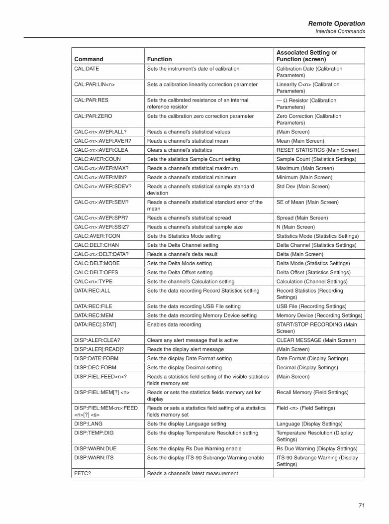
71
Remote OperationInterface Commands
Command FunctionAssociated Setting or Function (screen)
CAL:DATE Sets the instrument’s date of calibration Calibration Date (Calibration Parameters)
CAL:PAR:LIN<n> Sets a calibration linearity correction parameter Linearity C<n> (Calibration Parameters)
CAL:PAR:RES Sets the calibrated resistance of an internal reference resistor
— W Resistor (Calibration Parameters)
CAL:PAR:ZERO Sets the calibration zero correction parameter Zero Correction (Calibration Parameters)
CALC<n>:AVER:ALL? Reads a channel’s statistical values (Main Screen)
CALC<n>:AVER:AVER? Reads a channel’s statistical mean Mean (Main Screen)
CALC<n>:AVER:CLEA Clears a channel’s statistics RESET STATISTICS (Main Screen)
CALC:AVER:COUN Sets the statistics Sample Count setting Sample Count (Statistics Settings)
CALC<n>:AVER:MAX? Reads a channel’s statistical maximum Maximum (Main Screen)
CALC<n>:AVER:MIN? Reads a channel’s statistical minimum Minimum (Main Screen)
CALC<n>:AVER:SDEV? Reads a channel’s statistical sample standard deviation
Std Dev (Main Screen)
CALC<n>:AVER:SEM? Reads a channel’s statistical standard error of the mean
SE of Mean (Main Screen)
CALC<n>:AVER:SPR? Reads a channel’s statistical spread Spread (Main Screen)
CALC<n>:AVER:SSIZ? Reads a channel’s statistical sample size N (Main Screen)
CALC:AVER:TCON Sets the Statistics Mode setting Statistics Mode (Statistics Settings)
CALC:DELT:CHAN Sets the Delta Channel setting Delta Channel (Statistics Settings)
CALC<n>:DELT:DATA? Reads a channel’s delta result Delta (Main Screen)
CALC:DELT:MODE Sets the Delta Mode setting Delta Mode (Statistics Settings)
CALC:DELT:OFFS Sets the Delta Offset setting Delta Offset (Statistics Settings)
CALC<n>:TYPE Sets the channel’s Calculation setting Calculation (Channel Settings)
DATA:REC:ALL Sets the data recording Record Statistics setting Record Statistics (Recording Settings)
DATA:REC:FILE Sets the data recording USB File setting USB File (Recording Settings)
DATA:REC:MEM Sets the data recording Memory Device setting Memory Device (Recording Settings)
DATA:REC[:STAT] Enables data recording START/STOP RECORDING (Main Screen)
DISP:ALER:CLEA? Clears any alert message that is active CLEAR MESSAGE (Main Screen)
DISP:ALER[:READ]? Reads the display alert message (Main Screen)
DISP:DATE:FORM Sets the display Date Format setting Date Format (Display Settings)
DISP:DEC:FORM Sets the display Decimal setting Decimal (Display Settings)
DISP:FIEL:FEED<n>? Reads a statistics field setting of the visible statistics fields memory set
(Main Screen)
DISP:FIEL:MEM[?] <n> Reads or sets the statistics fields memory set for display
Recall Memory (Field Settings)
DISP:FIEL:MEM<n>:FEED <n>[?] <s>
Reads or sets a statistics field setting of a statistics fields memory set
Field <n> (Field Settings)
DISP:LANG Sets the display Language setting Language (Display Settings)
DISP:TEMP:DIG Sets the display Temperature Resolution setting Temperature Resolution (Display Settings)
DISP:WARN:DUE Sets the display Rs Due Warning enable Rs Due Warning (Display Settings)
DISP:WARN:ITS Sets the display ITS-90 Subrange Warning enable ITS-90 Subrange Warning (Display Settings)
FETC? Reads a channel’s latest measurement

1594A/1595A Super-ThermometerInterface Commands
72
Command FunctionAssociated Setting or Function (screen)
INIT:CONT Starts or stops measurement START/STOP MEASURING (Main Screen)
INIT:STOP:BEEP Sets the stop timer’s Timer Beep setting Stop Timer Enable (Timing Settings)
INIT:STOP:DUR Sets the stop timer’s Timer Duration setting Stop Timer Duration (Timing Settings)
INIT:STOP[:STAT] Sets the Stop Timer Enable Stop Timer Enable (Timing Settings)
INIT:STOP:TIME? Reads the stop timer’s time remaining Stop Timer time remaining (Main Screen)
INP<n>:CURR Sets a channel’s Sensing Current setting Sensing Current (Channel Settings)
INP<n>:CURR:DATA? Reads a channel’s actual sensing current
INP<n>:CURR:STAN Sets a channel’s Standby Current enable Standby Current (Channel Settings)
INP:PROB:ADD Adds a new probe definition to the Probe Library ADD PROBE (Probe Menu)
INP:PROB:COUN? Reads the number of probe definitions in the Probe Library
INP:PROB:DEL Deletes a probe definition from the Resistor Library DELETE PROBE (Manage Probes)
INP:PROB:FIRS? Reads the ID of the first probe in the Probe Library
INP<n>:PROB:IDEN Assigns a probe definition to the channel ASSIGN PROBE (Channel Menu)
INP:PROB:NEXT? Reads the ID of the next probe in the Probe Library
INP:PROB:PAR Sets the value of a setting in a resistor definition EDIT PROBE (Probe Menu)
INP:PROB:TEST? Reads the temperature calculated from resistance using the probe definition
TEST CALCULATION (Edit Probe)
INP:REAR<n>:RS:IDEN Sets the reference resistor assigned to a rear reference resistor input
ASSIGN RESISTOR (Set Up Rs)
INP:RS:ADD Adds a new resistor definition to the Resistor Library ADD RESISTOR (Define Resistor)
INP:RS:COUN? Reads the number of resistor definitions in the Resistor Library
INP:RS:DEL Delete the resistor ID from the Resistor Library DELETE RESISTOR (Manage Resistors)
INP:RS:FIRS? Reads the ID of the first resistor in the Resistor Library
INP<n>:RS:IDEN Sets the reference resistor assigned to a front reference resistor input
ASSIGN RESISTOR (Set Up Rs)
INP:RS:NEXT? Reads the ID of the next resistor in the Resistor Library
INP:RS:OVEN:STAB Reads the oven stable condition
INP:RS:PAR Sets the value of a setting in a resistor definition EDIT RESISTOR (Define Resistor)
INP<n>:RS:ROUT Sets a channel’s Reference Resistor (Rs) setting
ROUT:CLOS Selects one channel for measurement
ROUT:CLOS:STAT? Returns the channel number of whatever channel is actively being measured
Active Channel (Main Screen)
ROUT:SCAN Enables channels for scanning
ROUT:SCAN:ADD Adds channels to the scan list
ROUT:SCAN:ALT Sets the scan Alternate Reference setting Alternate Reference (Scan Settings)
ROUT:SCAN:DEL Removes channels from the scan list
ROUT:SCAN:REF Sets the scan Reference Channel setting Reference Channel (Scan Settings)
ROUT:SCAN:REP Sets the scan Repeat Count setting Repeat Count (Scan Settings)
ROUT:SCAN:STAT Sets the Scan Enable setting Scan Enable (Scan Settings)
SENS:APER Sets the measurement time and Display Interval Display Interval (Timing Settings)
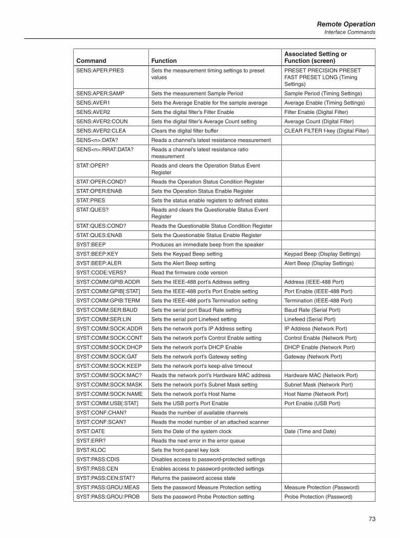
73
Remote OperationInterface Commands
Command FunctionAssociated Setting or Function (screen)
SENS:APER:PRES Sets the measurement timing settings to preset values
PRESET PRECISION PRESET FAST PRESET LONG (Timing Settings)
SENS:APER:SAMP Sets the measurement Sample Period Sample Period (Timing Settings)
SENS:AVER1 Sets the Average Enable for the sample average Average Enable (Timing Settings)
SENS:AVER2 Sets the digital filter’s Filter Enable Filter Enable (Digital Filter)
SENS:AVER2:COUN Sets the digital filter’s Average Count setting Average Count (Digital Filter)
SENS:AVER2:CLEA Clears the digital filter buffer CLEAR FILTER f-key (Digital Filter)
SENS<n>:DATA? Reads a channel’s latest resistance measurement
SENS<n>:RRAT:DATA? Reads a channel’s latest resistance ratio measurement
STAT:OPER? Reads and clears the Operation Status Event Register
STAT:OPER:COND? Reads the Operation Status Condition Register
STAT:OPER:ENAB Sets the Operation Status Enable Register
STAT:PRES Sets the status enable registers to defined states
STAT:QUES? Reads and clears the Questionable Status Event Register
STAT:QUES:COND? Reads the Questionable Status Condition Register
STAT:QUES:ENAB Sets the Questionable Status Enable Register
SYST:BEEP Produces an immediate beep from the speaker
SYST:BEEP:KEY Sets the Keypad Beep setting Keypad Beep (Display Settings)
SYST:BEEP:ALER Sets the Alert Beep setting Alert Beep (Display Settings)
SYST:CODE:VERS? Read the firmware code version
SYST:COMM:GPIB:ADDR Sets the IEEE-488 port’s Address setting Address (IEEE-488 Port)
SYST:COMM:GPIB[:STAT] Sets the IEEE-488 port’s Port Enable setting Port Enable (IEEE-488 Port)
SYST:COMM:GPIB:TERM Sets the IEEE-488 port’s Termination setting Termination (IEEE-488 Port)
SYST:COMM:SER:BAUD Sets the serial port Baud Rate setting Baud Rate (Serial Port)
SYST:COMM:SER:LIN Sets the serial port Linefeed setting Linefeed (Serial Port)
SYST:COMM:SOCK:ADDR Sets the network port’s IP Address setting IP Address (Network Port)
SYST:COMM:SOCK:CONT Sets the network port’s Control Enable setting Control Enable (Network Port)
SYST:COMM:SOCK:DHCP Sets the network port’s DHCP Enable DHCP Enable (Network Port)
SYST:COMM:SOCK:GAT Sets the network port’s Gateway setting Gateway (Network Port)
SYST:COMM:SOCK:KEEP Sets the network port’s keep-alive timeout
SYST:COMM:SOCK:MAC? Reads the network port’s Hardware MAC address Hardware MAC (Network Port)
SYST:COMM:SOCK:MASK Sets the network port’s Subnet Mask setting Subnet Mask (Network Port)
SYST:COMM:SOCK:NAME Sets the network port’s Host Name Host Name (Network Port)
SYST:COMM:USB[:STAT] Sets the USB port’s Port Enable Port Enable (USB Port)
SYST:CONF:CHAN? Reads the number of available channels
SYST:CONF:SCAN? Reads the model number of an attached scanner
SYST:DATE Sets the Date of the system clock Date (Time and Date)
SYST:ERR? Reads the next error in the error queue
SYST:KLOC Sets the front-panel key lock
SYST:PASS:CDIS Disables access to password-protected settings
SYST:PASS:CEN Enables access to password-protected settings
SYST:PASS:CEN:STAT? Returns the password access state
SYST:PASS:GROU:MEAS Sets the password Measure Protection setting Measure Protection (Password)
SYST:PASS:GROU:PROB Sets the password Probe Protection setting Probe Protection (Password)
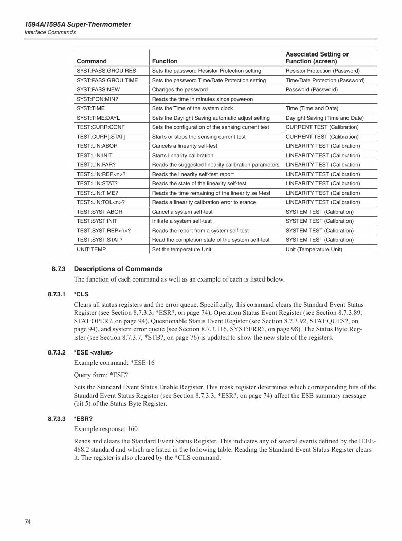
1594A/1595A Super-ThermometerInterface Commands
74
Command FunctionAssociated Setting or Function (screen)
SYST:PASS:GROU:RES Sets the password Resistor Protection setting Resistor Protection (Password)
SYST:PASS:GROU:TIME Sets the password Time/Date Protection setting Time/Date Protection (Password)
SYST:PASS:NEW Changes the password Password (Password)
SYST:PON:MIN? Reads the time in minutes since power-on
SYST:TIME Sets the Time of the system clock Time (Time and Date)
SYST:TIME:DAYL Sets the Daylight Saving automatic adjust setting Daylight Saving (Time and Date)
TEST:CURR:CONF Sets the configuration of the sensing current test CURRENT TEST (Calibration)
TEST:CURR[:STAT] Starts or stops the sensing current test CURRENT TEST (Calibration)
TEST:LIN:ABOR Cancels a linearity self-test LINEARITY TEST (Calibration)
TEST:LIN:INIT Starts linearity calibration LINEARITY TEST (Calibration)
TEST:LIN:PAR? Reads the suggested linearity calibration parameters LINEARITY TEST (Calibration)
TEST:LIN:REP<n>? Reads the linearity self-test report LINEARITY TEST (Calibration)
TEST:LIN:STAT? Reads the state of the linearity self-test LINEARITY TEST (Calibration)
TEST:LIN:TIME? Reads the time remaining of the linearity self-test LINEARITY TEST (Calibration)
TEST:LIN:TOL<n>? Reads a linearity calibration error tolerance LINEARITY TEST (Calibration)
TEST:SYST:ABOR Cancel a system self-test SYSTEM TEST (Calibration)
TEST:SYST:INIT Initiate a system self-test SYSTEM TEST (Calibration)
TEST:SYST:REP<n>? Reads the report from a system self-test SYSTEM TEST (Calibration)
TEST:SYST:STAT? Read the completion state of the system self-test SYSTEM TEST (Calibration)
UNIT:TEMP Set the temperature Unit Unit (Temperature Unit)
8.7.3 Descriptions of Commands
The function of each command as well as an example of each is listed below.
8.7.3.1 *CLS
Clears all status registers and the error queue. Specifically, this command clears the Standard Event Status Register (see Section 8.7.3.3, *ESR?, on page 74), Operation Status Event Register (see Section 8.7.3.89, STAT:OPER?, on page 94), Questionable Status Event Register (see Section 8.7.3.92, STAT:QUES?, on page 94), and system error queue (see Section 8.7.3.116, SYST:ERR?, on page 98). The Status Byte Reg-ister (see Section 8.7.3.7, *STB?, on page 76) is updated to show the new state of the registers.
8.7.3.2 *ESE <value>
Example command: *ESE 16
Query form: *ESE?
Sets the Standard Event Status Enable Register. This mask register determines which corresponding bits of the Standard Event Status Register (see Section 8.7.3.3, *ESR?, on page 74) affect the ESB summary message (bit 5) of the Status Byte Register.
8.7.3.3 *ESR?
Example response: 160
Reads and clears the Standard Event Status Register. This indicates any of several events defined by the IEEE-488.2 standard and which are listed in the following table. Reading the Standard Event Status Register clears it. The register is also cleared by the *CLS command.
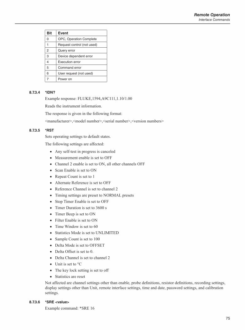
75
Remote OperationInterface Commands
Bit Event
0 OPC, Operation Complete
1 Request control (not used)
2 Query error
3 Device dependent error
4 Execution error
5 Command error
6 User request (not used)
7 Power on
8.7.3.4 *IDN?
Example response: FLUKE,1594,A9C111,1.10/1.00
Reads the instrument information.
The response is given in the following format:
<manufacturer>,<model number>,<serial number>,<version numbers>
8.7.3.5 *RST
Sets operating settings to default states.
The following settings are affected:
Any self-test in progress is canceled Measurement enable is set to OFF Channel 2 enable is set to ON, all other channels OFF Scan Enable is set to ON Repeat Count is set to 1 Alternate Reference is set to OFF Reference Channel is set to channel 2 Timing settings are preset to NORMAL presets Stop Timer Enable is set to OFF Timer Duration is set to 3600 s Timer Beep is set to ON Filter Enable is set to ON Time Window is set to 60 Statistics Mode is set to UNLIMITED Sample Count is set to 100 Delta Mode is set to OFFSET Delta Offset is set to 0. Delta Channel is set to channel 2 Unit is set to °C The key lock setting is set to off Statistics are reset
Not affected are channel settings other than enable, probe definitions, resistor definitions, recording settings, display settings other than Unit, remote interface settings, time and date, password settings, and calibration settings.
8.7.3.6 *SRE <value>
Example command: *SRE 16
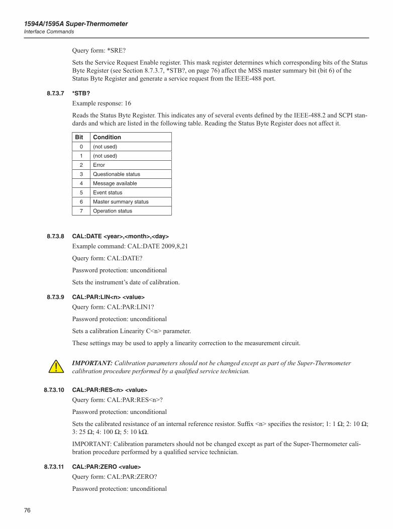
1594A/1595A Super-ThermometerInterface Commands
76
Query form: *SRE?
Sets the Service Request Enable register. This mask register determines which corresponding bits of the Status Byte Register (see Section 8.7.3.7, *STB?, on page 76) affect the MSS master summary bit (bit 6) of the Status Byte Register and generate a service request from the IEEE-488 port.
8.7.3.7 *STB?
Example response: 16
Reads the Status Byte Register. This indicates any of several events defined by the IEEE-488.2 and SCPI stan-dards and which are listed in the following table. Reading the Status Byte Register does not affect it.
Bit Condition
0 (not used)
1 (not used)
2 Error
3 Questionable status
4 Message available
5 Event status
6 Master summary status
7 Operation status
8.7.3.8 CAL:DATE <year>,<month>,<day>
Example command: CAL:DATE 2009,8,21
Query form: CAL:DATE?
Password protection: unconditional
Sets the instrument’s date of calibration.
8.7.3.9 CAL:PAR:LIN<n> <value>
Query form: CAL:PAR:LIN1?
Password protection: unconditional
Sets a calibration Linearity C<n> parameter.
These settings may be used to apply a linearity correction to the measurement circuit.
IMPORTANT: Calibration parameters should not be changed except as part of the Super-Thermometer calibration procedure performed by a qualified service technician.
8.7.3.10 CAL:PAR:RES<n> <value>
Query form: CAL:PAR:RES<n>?
Password protection: unconditional
Sets the calibrated resistance of an internal reference resistor. Suffix <n> specifies the resistor; 1: 1 Ω; 2: 10 Ω; 3: 25 Ω; 4: 100 Ω; 5: 10 kΩ.
IMPORTANT: Calibration parameters should not be changed except as part of the Super-Thermometer cali-bration procedure performed by a qualified service technician.
8.7.3.11 CAL:PAR:ZERO <value>
Query form: CAL:PAR:ZERO?
Password protection: unconditional
77
Remote OperationInterface Commands
Sets the calibration Zero Correction parameter.
This setting may be used to apply a zero correction to the measurement circuit.
IMPORTANT: Calibration parameters should not be changed except as part of the Super-Thermometer calibration procedure performed by a qualified service technician.
8.7.3.12 CALC<n>:AVER:ALL?
Example command: CALC3:AVER:ALL?
Example response: 231.928581,0.000488,0.000212,231.92862,231.928479,23
Example response: 231.928581,,,231.928581,231.928581,1
Example response: ,,,,,0
Reads a channel’s statistical mean, standard deviation, standard error of the mean, maximum, minimum, and sample size.
Suffix <n> is the channel number: 1 through 4 for the corresponding front channel input, 5 through 14 for channels of the first attached scanner, and 15 through 24 for channels of the second attached scanner.
The response is given in the following format:
<mean>,<std. dev.>,<std. error>,<max.>,<min.>,<N>
If a value is invalid or not available, the field is left empty in the response (the associated field separator comma remains).
The statistical values have the same unit as the measurement returned by the FETC? command. If the calcula-tion is temperature, the unit of measurement is determined by the Unit setting (see Section 5.7.4.5, TEMPER-ATURE UNIT (F5), on page 50).
8.7.3.13 CALC<n>:AVER:AVER?
Example command: CALC3:AVER:AVER?
Example response: 231.928581
Reads a channel’s statistical mean (see Section 5.7.4.2, FIELD SETTINGS (F2), on page 48).
Suffix <n> is the channel number: 1 through 4 for the corresponding front channel input, 5 through 14 for channels of the first attached scanner, and 15 through 24 for channels of the second attached scanner.
The returned value has the same units as the measurement returned by the FETC? command. If the calculation is temperature, the unit of measurement is determined by the Unit setting see Section 5.7.4.5, TEMPERA-TURE UNIT (F5), on page 50).
If no result is available, no response is returned and error -230,“Data corrupt or stale” is generated in the error queue.
8.7.3.14 CALC[<n>]:AVER:CLEA
Example command: CALC:AVER:CLEAR
Clears a channel’s statistics.
Suffix <n> is the channel number: 1 through 4 for the corresponding front channel input, 5 through 14 for channels of the first attached scanner, and 15 through 24 for channels of the second attached scanner. If the suffix number is omitted, statistics for all channels are cleared. This is equivalent to pressing the RESET STA-TISTICS function key in the Main Screen.
The *RST command also clears the statistics for all channels.
8.7.3.15 CALC:AVER:COUN <value>
Example command: CALC:AVER:COUNT 50

1594A/1595A Super-ThermometerInterface Commands
78
Query form: CALC:AVER:COUN?
Alternate parameter: DEF, MIN, MAX
Sets the statistics Sample Count setting.
Parameter <value> is the maximum number of samples in the moving window when the Statistics Mode set-ting is LIMITED (see Section 8.7.3.22, CALC:AVER:TCON NORM|MOV, on page 79). The range is 1 through 100 and the default is 100.
The *RST command sets Sample Count to 100.
8.7.3.16 CALC<n>:AVER:MAX?
Example command: CALC3:AVER:MAX?
Example response: 231.928833
Reads a channel’s statistical maximum (see Section 5.7.4.2, FIELD SETTINGS (F2), on page 48).
Suffix <n> is the channel number: 1 through 4 for the corresponding front channel input, 5 through 14 for channels of the first attached scanner, and 15 through 24 for channels of the second attached scanner.
The returned value has the same units as the measurement returned by the FETC? command. If the calculation is temperature, the unit of measurement is determined by the Unit setting (see Section 5.7.4.5, TEMPERA-TURE UNIT (F5), on page 50).
If no result is available, no response is returned and error -230,“Data corrupt or stale” is generated in the error queue.
8.7.3.17 CALC<n>:AVER:MIN?
Example command: CALC3:AVER:MIN?
Example response: 231.928207
Reads a channel’s statistical minimum (see Section 5.7.4.2, FIELD SETTINGS (F2), on page 48).
Suffix <n> is the channel number: 1 through 4 for the corresponding front channel input, 5 through 14 for channels of the first attached scanner, and 15 through 24 for channels of the second attached scanner.
The returned value has the same units as the measurement returned by the FETC? command. If the calculation is temperature, the unit of measurement is determined by the Unit setting (see Section 5.7.4.5, TEMPERA-TURE UNIT (F5), on page 50).
If no result is available, no response is returned and error -230,“Data corrupt or stale” is generated in the error queue.
8.7.3.18 CALC<n>:AVER:SDEV?
Example command: CALC3:AVER:SDEV?
Example response: 0.000144
Reads a channel’s statistical sample standard deviation (see Section 5.7.4.2, FIELD SETTINGS (F2), on page 48).
Suffix <n> is the channel number: 1 through 4 for the corresponding front channel input, 5 through 14 for channels of the first attached scanner, and 15 through 24 for channels of the second attached scanner.
The returned value has the same units as the measurement returned by the FETC? command. If the calculation is temperature, the unit of measurement is determined by the Unit setting (see Section 5.7.4.5, TEMPERA-TURE UNIT (F5), on page 50).
The standard deviation is available if at least four measurements have been acquired from the channel. If no result is available, no response is returned and error -230,“Data corrupt or stale” is generated in the error queue.
79
Remote OperationInterface Commands
8.7.3.19 CALC<n>:AVER:SEM?
Example command: CALC3:AVER:SEM?
Example response: 0.000039
Reads a channel’s statistical standard error of the mean (see Section 5.7.4.2, FIELD SETTINGS (F2), on page 48).
Suffix <n> is the channel number: 1 through 4 for the corresponding front channel input, 5 through 14 for channels of the first attached scanner, and 15 through 24 for channels of the second attached scanner.
The returned value has the same units as the measurement returned by the FETC? command. If the calculation is temperature, the unit of measurement is determined by the Unit setting (see Section 5.7.4.5, TEMPERA-TURE UNIT (F5), on page 50).
The standard error of the mean is available if at least four measurements have been acquired from the channel. If no result is available, no response is returned and error -230,“Data corrupt or stale” is generated in the error queue.
8.7.3.20 CALC<n>:AVER:SPR?
Example command: CALC3:AVER:SPREAD?
Example response: 0.000626
Reads a channel’s statistical spread (see Section 5.7.4.2, FIELD SETTINGS (F2), on page 48).
Suffix <n> is the channel number: 1 through 4 for the corresponding front channel input, 5 through 14 for channels of the first attached scanner, and 15 through 24 for channels of the second attached scanner.
The returned value has the same units as the measurement returned by the FETC? command. If the calculation is temperature, the unit of measurement is determined by the Unit setting (see Temperature Unit (F5) in the Display Menu).
If no result is available, no response is returned and error -230,“Data corrupt or stale” is generated in the error queue.
8.7.3.21 CALC<n>:AVER:SSIZ?
Example command: CALC3:AVER:SSIZE?
Example response: 40
Reads a channel’s statistical sample size (see Section 5.7.4.2, FIELD SETTINGS (F2), on page 48).
Suffix <n> is the channel number: 1 through 4 for the corresponding front channel input, 5 through 14 for channels of the first attached scanner, and 15 through 24 for channels of the second attached scanner.
8.7.3.22 CALC:AVER:TCON NORM|MOV
Query form: CALC:AVER:TCON?
Alternate parameter: DEF
Sets the Statistics Mode setting (see Section 5.7.4.3, STATISTICS SETTINGS (F3), on page 49).
If the parameter is NORM (normal), the sample size is unlimited; the sample set accumulates until the statis-tics are cleared. If the parameter is MOV (moving window), the sample size is limited, and once the sample size reaches the Sample Count value, earliest samples are removed from the sample set when new samples are added.
The *RST command sets Statistics Mode to the default setting which is NORM (UNLIMITED).
8.7.3.23 CALC:DELT:CHAN <channel>
Example command: CALC:DELT:CHAN 1
Query form: CALC:DELT:CHAN?
1594A/1595A Super-ThermometerInterface Commands
80
Sets the Delta Channel setting (see Section 5.7.4.3, STATISTICS SETTINGS (F3), on page 49).
Parameter <channel> is the channel number to use as the reference, which may be 1 through 4 for the cor-responding front channel input, 5 through 14 for channels of the first attached scanner, and 15 through 24 for channels of the second attached scanner.
This setting is only meaningful when Delta Mode is set to CHANNEL.
The *RST command sets Delta Channel to 2.
8.7.3.24 CALC<n>:DELT:DATA?
Example command: CALC3:DELT:DATA?
Example response: 0.104428
Reads a channel’s delta result (see Section 5.7.4.2, FIELD SETTINGS (F2), on page 48).
Suffix <n> is the channel number: 1 through 4 for the corresponding front channel input, 5 through 14 for channels of the first attached scanner, and 15 through 24 for channels of the second attached scanner.
No result will be available if no measurement has been acquired on a designated Delta Channel or if the two measurements have different units. If no result is available, no response is returned and error -230,“Data cor-rupt or stale” is generated in the error queue.
8.7.3.25 CALC:DELT:MODE OFFS|CHAN
Query form: CALC:DELT:MODE?
Alternate parameter: DEF
Sets the Delta Mode setting (see Section 5.7.4.3, STATISTICS SETTINGS (F3), on page 49).
If the parameter is OFFS (OFFSET), the delta result is calculated by subtracting the Delta Offset setting’s value from the channel’s measurement. If the parameter is CHAN (CHANNEL), the delta result is calculated by subtracting the measurement from the channel determined by the Delta Channel setting from the channel’s measurement.
The *RST command sets Delta Mode to the default setting which is OFFS.
8.7.3.26 CALC:DELT:OFFS <value>
Query form: CALC:DELT:OFFS?
Sets the Delta Offset setting (see Section 5.7.4.3, STATISTICS SETTINGS (F3), on page 49).
This setting is only meaningful when Delta Mode is set to OFFSET.
The *RST command sets Delta Offset to the default value which is 0.
8.7.3.27 CALC<n>:TYPE TEMP|RES|RAT
Query form: CALC<n>:TYPE?
Alternate parameter: DEF
Sets the channel’s Calculation setting.
Suffix <n> specifies the channel number: 1 through 4 for the corresponding front channel input, 5 through 14 for channels of the first attached scanner, and 15 through 24 for channels of the second attached scanner. The default setting may depend on the probe and reference resistor settings.
8.7.3.28 DATA:REC:ALL <boolean>
Query form: DATA:REC:ALL?
Alternate parameter: DEF
Sets the data recording Record Statistics setting (see Section 5.7.3.4.1, RECORDING SETTINGS (F1), on page 42). The default is ON.
81
Remote OperationInterface Commands
8.7.3.29 DATA:REC:FILE <name>
Query form: DATA:REC:FILE?
Sets the data recording USB File name (see Section 5.7.3.4.1, RECORDING SETTINGS (F1), on page 42).
8.7.3.30 DATA:REC:MEM INT|USB|BOTH
Query form: DATA:REC:MEM?
Sets the data recording Memory Device (see Section 5.7.3.4.1, RECORDING SETTINGS (F1), on page 42).
8.7.3.31 DATA:REC[:STAT] <boolean>
Query form: DATA:REC?
Starts or stops recording. This is equivalent to pressing the START RECORDING or STOP RECORDING function key in the Main Screen. A <boolean> parameter value 1 enables recording; 0 disables recording.
The *RST command has no effect on this setting.
8.7.3.32 DISP:ALER:CLEA
Clears any alert message that is active.
8.7.3.33 DISP:ALER[:READ]?
Example response: 1,“Maximum temperature exceeded”
Reads the active alert message. The response given is the alert message number and description, comma-sepa-rated and with the description enclosed in quotation marks. If no alert message is active, the response is 0,”No alert”. The following table lists the possible responses:
Alert Cause
0,“No alert” No alert message is active.
1,“Maximum temperature exceeded” A measured temperature exceeds the limit defined for a probe.
2,“ITS-90 subrange exceeded” A measured temperature is outside the ITS-90 subranges defined for a probe.
3,“Resistor due for calibration” A defined resistor in the Resistor Library is past due for calibration.
The active alert message may be cleared using the DISP:ALER:CLEA command.
8.7.3.34 DISP:DATE:FORM YMD|DMY|MDY
Query form: DISP:DATE:FORM?
Alternate parameter: DEF
Sets the display Date Format setting (see Section 5.7.4.1, USER SETTINGS (F1), on page 47). The default setting is YMD.
8.7.3.35 DISP:DEC:FORM PER|COMM
Query form: DISP:DATE:FORM?
Alternate parameter: DEF
Sets the display Decimal setting (see Section 5.7.4.1, USER SETTINGS (F1), on page 47). The default set-ting is PER.
8.7.3.36 DISP:FIEL:FEED<n>?
Example command: DISP:FIEL:FEED4?
Example response: DEF
1594A/1595A Super-ThermometerInterface Commands
82
Reads a statistics field setting of the visible statistics fields memory set (see Section 5.7.4.2, FIELD SET-TINGS (F2), on page 48).
Suffix <n> is the field number, which may be 1 through 4. The response will be one of the following: MEAN, SDEV, SEM, MAX, MIN, SPR, N, DELT, RES, RAT, TIME, or DATE.
8.7.3.37 DISP:FIEL:MEM <n>
Example command: DISP:FIEL:MEM 4
Query form: DISP:FIEL:MEM<n>?
Alternate parameter: MIN, MAX, DEF
Reads or sets a statistics fields memory set for display (see Section 5.7.4.2, FIELD SETTINGS (F2), on page 48).
The parameter <n> may be a number from 1 to 4.
8.7.3.38 DISP:FIEL:MEM<n1>:FEED<n2> <feed>
Example command: DISP:FIEL:MEM4:FEED4 TIME
Query form: DISP:FIEL:MEM<n1>:FEED<n2>?
Alternate parameter: DEF
Reads or sets a statistics field setting of a statistics fields memory set (see Section 5.7.4.2, FIELD SETTINGS (F2), on page 48).
Suffix <n1> is the memory set number, which may be 1 through 4. Suffix <n2> is the field number, which may be 1 through 4. The parameter <feed> may be one of the following: MEAN, SDEV, SEM, MAX, MIN, SPR, N, DELT, RES, RAT, TIME, or DATE.
8.7.3.39 DISP:HELP <boolean>
Query form: DISP:HELP?
Sets the display Start-up Help Screen enable.
This setting determines whether the Start-up Help Screen appears at power-on. By default it is 1 and the Start-up Help Screen appears each time the instrument is powered on. If the setting is changed to 0, the Start-up Help Screen will no longer appear.
8.7.3.40 DISP:LANG ENGLISH|CHINESE|JAPANESE|SPANISH|GERMAN|FRENCH|RUSSIAN
Query form: DISP:LANG?
Alternate parameter: DEF
Sets the display Language setting (see Section 5.7.4.1, USER SETTINGS (F1), on page 47). The default setting is ENGLISH.
8.7.3.41 DISP:TEMP:DIG <digits>
Query form: DISP:TEMP:DIG?
Alternate parameter: DEF, MIN, MAX
Sets the display Temperature Resolution setting (see Section 5.7.4.1, USER SETTINGS (F1), on page 47).
Parameter <digits> specifies the number of decimal places. The range is 1 to 6 and the default is 5.
8.7.3.42 DISP:WARN:DUE <boolean>
Query form: DISP:WARN:DUE?
Alternate parameter: DEF
83
Remote OperationInterface Commands
Sets the display Rs Due Alert enable (see Section 5.7.4.1, USER SETTINGS (F1), on page 47). The default setting is OFF.
8.7.3.43 DISP:WARN:ITS <boolean>
Query form: DISP:WARN:ITS?
Alternate parameter: DEF
Sets the display ITS-90 Subrange Alert enable (see Section 5.7.4.1, USER SETTINGS (F1), on page 47). The default setting is ON.
8.7.3.44 FETC? <channel>
Example command: FETCH? 4
Example response: 231.92811,C,4,2009-03-23 14:33:20
Reads a channel’s latest measurement.
The <channel> parameter may be 1 through 4 for corresponding front channel inputs, 5 through 14 for chan-nels of a first attached scanner, or 15 through 24 for channels of a second attached scanner. If the <channel> parameter is omitted, the latest measurement regardless of channel is returned.
If a measurement is available, the response is given in the following format:
<measurement value>,<unit>,<channel number>,<date and time>
<measurement value> is the value of the measurement. It may be a temperature, resistance, or resistance ratio. The number of decimal places depends on the measured parameter. Trailing zeros are omitted.
<unit> may be “C”, “F”, or “K” for a temperature measurement; “O” for a resistance measurement, or “R” for a resistance ratio measurement.
<channel number> is 1 through 4 for corresponding front channel inputs, 5 through 14 for channels of a first scanner, or 15 through 24 for channels of a second scanner.
<time and date> gives the time and date of the measurement, separated by one space. The time is in 24-hour format. The date is in the format YYYY-MM-DD.
If no measurement is available, no response is returned and error code -230, “Data corrupt or stale,” is gener-ated in the error queue. The command STAT:OPER? may be used first to determine whether a new measure-ment has completed, and command STAT:QUES:COND? may be used to determine whether the new measure-ment is valid before an attempt is made to read it.
8.7.3.45 INIT:CONT <boolean>
Query form: INIT:CONT?
Starts or stops measurement. This is equivalent to pressing the START MEASUREMENT or STOP MEA-SUREMENT function key in the Measurement Screen. A <boolean> parameter value 1 enables measurement; 0 disables measurement.
The *RST command disables measurement.
8.7.3.46 INIT:STOP:BEEP <boolean>
Query form: INIT:STOP:BEEP?
Alternate parameter: DEF
Sets the stop timer’s Audio Indication setting (see Section 5.7.3.2, TIMING SETTINGS (F2), on page 39).
The *RST command sets Timer Beep to the default option which is ON.
8.7.3.47 INIT:STOP:DUR <value>
Example command: INIT:STOP:DUR 1200
Query form: INIT:STOP:DUR?
1594A/1595A Super-ThermometerInterface Commands
84
Alternate parameter: DEF, MIN, MAX
Sets the stop timer’s Timer Duration setting (see Section 5.7.3.2, TIMING SETTINGS (F2), on page 39). The value is the number of seconds. The range is 1 to 86399 and the default is 3600 (one hour).
This setting is only meaningful when Stop Timer Enable is ON.
The *RST command sets Timer Duration to 3600.
8.7.3.48 INIT:STOP[:STAT] <boolean>
Query form: INIT:STOP?
Alternate parameter: DEF
Sets the Stop Timer Enable (see Section 5.7.3.2, TIMING SETTINGS (F2), on page 39).
The *RST command sets Stop Timer Enable to the default setting which is OFF.
8.7.3.49 INIT:STOP:TIME?
Example response: 874
Reads the stop timer’s time remaining.
The returned value is the time remaining in seconds. If the stop timer is disabled or measurement is not en-abled, the returned value is 0.
8.7.3.50 INP<n>:CURR <current>
Example command: INP1:CURR 1
Query form: INP<n>:CURR?
Alternate parameter: DEF, MIN, MAX
Sets a channel’s Sensing Current setting.
Suffix <n> specifies the channel number: 1 through 4 for the corresponding front channel input, 5 through 14 for channels of the first attached scanner, and 15 through 24 for channels of the second attached scanner.
The maximum and default values depend on the probe and reference resistor settings. The values may be read using the query form with alternate parameters MAX and DEF respectively.
The actual current may be reduced if the resistance is too high. The actual current may be read using the INP<n>:CURR:DATA? command.
8.7.3.51 INP<n>:CURR:DATA?
Reads a channel’s actual sensing current. It is the sensing current that was used when the latest measurement of the channel was acquired.
8.7.3.52 INP<n>:CURR:STAN <boolean>
Query form: INP<n>:CURR:STAN?
Alternate parameter: DEF
Sets a channel’s Standby Current enable.
A parameter value 1 enables the standby current. When enabled, sensing current is sourced from the channel’s terminals when measurement is enabled, even if the channel is not enabled or when another channel is being scanned. The default setting is 0 (OFF).
8.7.3.53 INP:PROB:ADD <id>
Example command: INP:PROB:ADD “PRT_A46002”
Password protection: Probe Protection
85
Remote OperationInterface Commands
Adds a new probe definition to the Probe Library. Before a probe can be assigned to a channel and tem-perature measured, the probe must have its definition added to the Probe Library (see Section 8.7.3.57, INP<n>:PROB:IDEN <id>, on page 85).
Parameter <id> is the ID of the new probe definition. It can contain letters, numerals, hyphens, periods, for-ward slashes, and underscores. It must be between one and 24 characters in length, inclusive.
If <id> is different from all other IDs in the Probe Library and space is available in the Probe Library, a new probe definition will be added and given the specified ID. The probe parameters will initially be set to default values. The command INP:PROB:PAR should be used to set the parameters.
If <id> matches the ID of a probe already in the Probe Library or the Probe Library is full, no new probe defi-nition is added, and error -224, “Illegal parameter value” will be generated in the error queue.
8.7.3.54 INP:PROB:COUN?
Alternate parameter: MAX
Reads the number of probe definitions in the Probe Library.
8.7.3.55 INP:PROB:DEL <id>
Example command: INP:PROB:DEL “PRT_A46002”
Password protection: Probe Protection
Deletes a probe definition from the Probe Library.
Parameter <id> is the ID of the probe definition to delete. If <id> does not match the ID of any probe in the Probe Library, nothing is deleted, and error -224, “Illegal parameter value” is generated in the error queue.
If the deleted probe was assigned to a channel the channel’s probe setting is changed to undefined (see Section 8.7.3.57, INP<n>:PROB:IDEN <id>, on page 85).
8.7.3.56 INP:PROB:FIRS?
Example response: “PRT_A46002”
Reads the ID of the first probe in the Probe Library. It also resets the library index used by the INP:PROB:NEXT? command.
If the Probe Library is empty the response is an empty string, “”.
8.7.3.57 INP<n>:PROB:IDEN <id>
Example command: INP1:PROB:IDEN “PRT_A46002”
Example command: INP2:PROB:IDEN NONE
Query form: INP<n>:PROB:IDEN?
Assigns a probe definition to the channel.
Suffix <n> specifies the channel number: 1 through 4 for the corresponding front channel input, 5 through 14 for channels of the first attached scanner, and 15 through 24 for channels of the second attached scanner.
Parameter <id> must either be the ID of a probe definition in the Probe Library, or “NONE” (undefined). En-closing quotations marks are optional. If <id> does not match the ID of a probe definition in the Probe Library, error -224,“Illegal parameter value” is generated in the error queue.
If a valid probe ID is assigned to the channel, the response to the query form is the ID of the probe enclosed in quotation marks. If the assigned probe is undefined, the response is “NONE” without quotation marks.
The channel’s Calculation setting will automatically be set to resistance if it was temperature when the chan-nel’s assigned probe is set to NONE.
8.7.3.58 INP:PROB:NEXT?
Example response: “A71040”
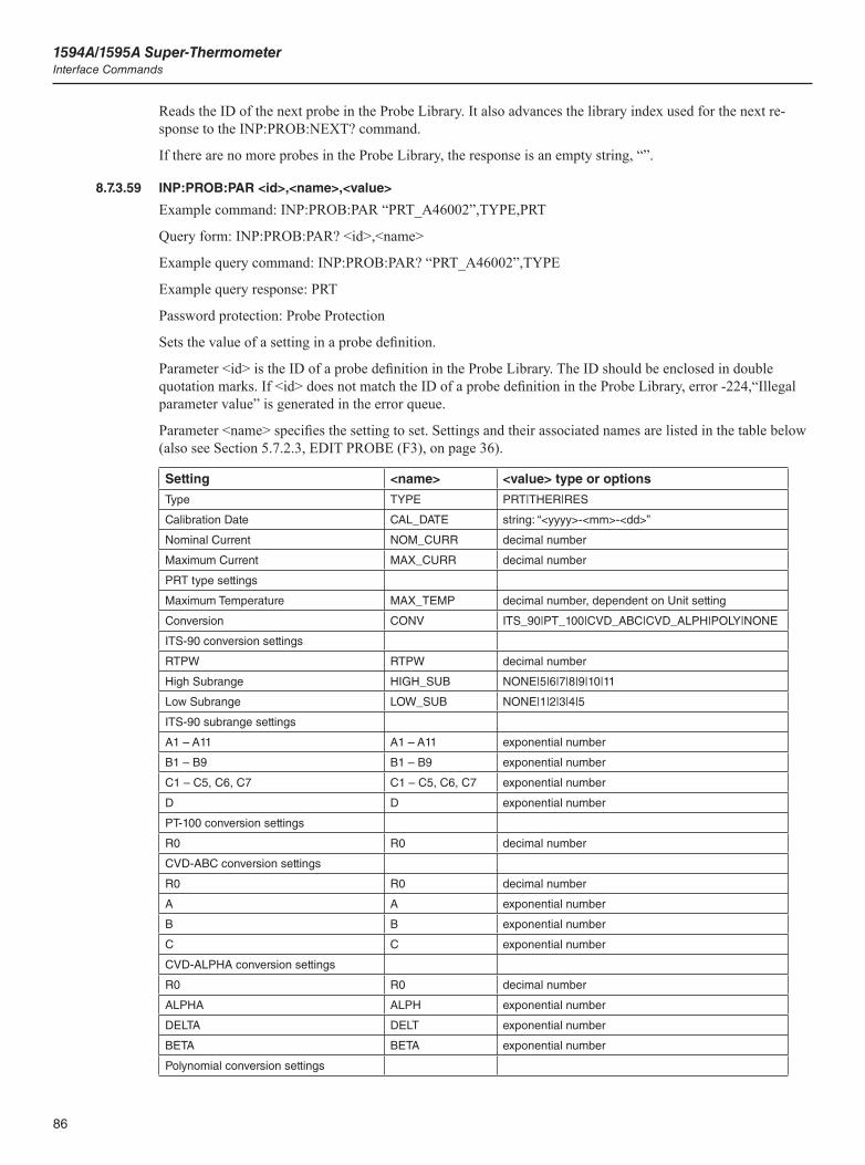
1594A/1595A Super-ThermometerInterface Commands
86
Reads the ID of the next probe in the Probe Library. It also advances the library index used for the next re-sponse to the INP:PROB:NEXT? command.
If there are no more probes in the Probe Library, the response is an empty string, “”.
8.7.3.59 INP:PROB:PAR <id>,<name>,<value>
Example command: INP:PROB:PAR “PRT_A46002”,TYPE,PRT
Query form: INP:PROB:PAR? <id>,<name>
Example query command: INP:PROB:PAR? “PRT_A46002”,TYPE
Example query response: PRT
Password protection: Probe Protection
Sets the value of a setting in a probe definition.
Parameter <id> is the ID of a probe definition in the Probe Library. The ID should be enclosed in double quotation marks. If <id> does not match the ID of a probe definition in the Probe Library, error -224,“Illegal parameter value” is generated in the error queue.
Parameter <name> specifies the setting to set. Settings and their associated names are listed in the table below (also see Section 5.7.2.3, EDIT PROBE (F3), on page 36).
Setting <name> <value> type or options
Type TYPE PRT|THER|RES
Calibration Date CAL_DATE string: “<yyyy>-<mm>-<dd>”
Nominal Current NOM_CURR decimal number
Maximum Current MAX_CURR decimal number
PRT type settings
Maximum Temperature MAX_TEMP decimal number, dependent on Unit setting
Conversion CONV ITS_90|PT_100|CVD_ABC|CVD_ALPH|POLY|NONE
ITS-90 conversion settings
RTPW RTPW decimal number
High Subrange HIGH_SUB NONE|5|6|7|8|9|10|11
Low Subrange LOW_SUB NONE|1|2|3|4|5
ITS-90 subrange settings
A1 – A11 A1 – A11 exponential number
B1 – B9 B1 – B9 exponential number
C1 – C5, C6, C7 C1 – C5, C6, C7 exponential number
D D exponential number
PT-100 conversion settings
R0 R0 decimal number
CVD-ABC conversion settings
R0 R0 decimal number
A A exponential number
B B exponential number
C C exponential number
CVD-ALPHA conversion settings
R0 R0 decimal number
ALPHA ALPH exponential number
DELTA DELT exponential number
BETA BETA exponential number
Polynomial conversion settings
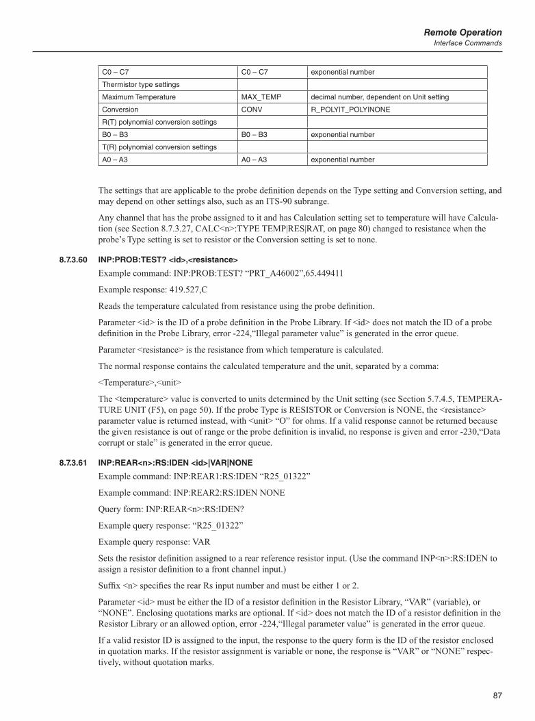
87
Remote OperationInterface Commands
C0 – C7 C0 – C7 exponential number
Thermistor type settings
Maximum Temperature MAX_TEMP decimal number, dependent on Unit setting
Conversion CONV R_POLY|T_POLY|NONE
R(T) polynomial conversion settings
B0 – B3 B0 – B3 exponential number
T(R) polynomial conversion settings
A0 – A3 A0 – A3 exponential number
The settings that are applicable to the probe definition depends on the Type setting and Conversion setting, and may depend on other settings also, such as an ITS-90 subrange.
Any channel that has the probe assigned to it and has Calculation setting set to temperature will have Calcula-tion (see Section 8.7.3.27, CALC<n>:TYPE TEMP|RES|RAT, on page 80) changed to resistance when the probe’s Type setting is set to resistor or the Conversion setting is set to none.
8.7.3.60 INP:PROB:TEST? <id>,<resistance>
Example command: INP:PROB:TEST? “PRT_A46002”,65.449411
Example response: 419.527,C
Reads the temperature calculated from resistance using the probe definition.
Parameter <id> is the ID of a probe definition in the Probe Library. If <id> does not match the ID of a probe definition in the Probe Library, error -224,“Illegal parameter value” is generated in the error queue.
Parameter <resistance> is the resistance from which temperature is calculated.
The normal response contains the calculated temperature and the unit, separated by a comma:
<Temperature>,<unit>
The <temperature> value is converted to units determined by the Unit setting (see Section 5.7.4.5, TEMPERA-TURE UNIT (F5), on page 50). If the probe Type is RESISTOR or Conversion is NONE, the <resistance> parameter value is returned instead, with <unit> “O” for ohms. If a valid response cannot be returned because the given resistance is out of range or the probe definition is invalid, no response is given and error -230,“Data corrupt or stale” is generated in the error queue.
8.7.3.61 INP:REAR<n>:RS:IDEN <id>|VAR|NONE
Example command: INP:REAR1:RS:IDEN “R25_01322”
Example command: INP:REAR2:RS:IDEN NONE
Query form: INP:REAR<n>:RS:IDEN?
Example query response: “R25_01322”
Example query response: VAR
Sets the resistor definition assigned to a rear reference resistor input. (Use the command INP<n>:RS:IDEN to assign a resistor definition to a front channel input.)
Suffix <n> specifies the rear Rs input number and must be either 1 or 2.
Parameter <id> must be either the ID of a resistor definition in the Resistor Library, “VAR” (variable), or “NONE”. Enclosing quotations marks are optional. If <id> does not match the ID of a resistor definition in the Resistor Library or an allowed option, error -224,“Illegal parameter value” is generated in the error queue.
If a valid resistor ID is assigned to the input, the response to the query form is the ID of the resistor enclosed in quotation marks. If the resistor assignment is variable or none, the response is “VAR” or “NONE” respec-tively, without quotation marks.
1594A/1595A Super-ThermometerInterface Commands
88
A channel’s Calculation setting will be changed from temperature to resistance (see Section 8.7.3.27, CALC<n>:TYPE TEMP|RES|RAT, on page 80) if its Reference Resistor (Rs) setting was set to the speci-fied input and the resistor assignment for the input is set to variable. A channel’s Reference Resistor (Rs) setting will be changed from the specified input to the internal 100 Ω resistor if the resistor assignment for the input is being set to none.
8.7.3.62 INP:RS:ADD <id>
Example command: INP:RS:ADD “R25_01322”
Password protection: Resistor Protection
Adds a new resistor definition to the Resistor Library. Before a resistor can be assigned to an input (see com-mands INP:RS:FRON:IDEN and INP:RS:REAR:IDEN) and used as a reference resistor, the resistor must have its definition added to the Resistor Library.
Parameter <id> is the ID of the new resistor definition. It can contain letters, numerals, hyphens, periods, for-ward slashes, and underscores. It must be between one and 22 characters in length, inclusive.
If <id> is different from all other IDs in the Resistor Library and space is available in the Resistor Library, a new resistor definition will be added and given the specified ID. The resistor parameters will initially be set to default values. The command INP:RS:PAR should be used to set the parameters.
If <id> matches the ID of a resistor already in the Resistor Library or the Resistor Library is full, no new resis-tor definition is added, and error -224, “Illegal parameter value” will be generated in the error queue.
8.7.3.63 INP:RS:COUN?
Reads the number of resistor definitions in the Resistor Library.
8.7.3.64 INP:RS:DEL <id>
Example command: CALC:PROB:DEL “R25_01322”
Password protection: Resistor Protection
Deletes a resistor definition from the Resistor Library.
Parameter <id> is the ID of the resistor definition to delete. If <id> does not match the ID of any resistor in the Resistor Library, nothing is deleted, and error -224, “Illegal parameter value” is generated in the error queue.
If the deleted resistor was assigned to an input (see commands INP:RS:FRON:IDEN and INP:RS:REAR:IDEN), the input’s reference resistor (Rs) setting will be changed to variable. The Calcula-tion setting for any channel that used the input for its Reference Resistor (Rs) setting will be changed from temperature or resistance to ratio.
8.7.3.65 INP:RS:FIRS?
Example response: “R25_01322”
Reads the ID of the first resistor in the Resistor Library. It also resets the catalog index used by the INP:RS:NEXT? command.
If the Probe Library is empty, no response is given and error -230,“Data corrupt or stale” is generated in the error queue.
8.7.3.66 INP<n>:RS:IDEN <id>|VAR|NONE
Example command: INP2:RS:IDEN “R25_01322”
Example command: INP4:RS:IDEN NONE
Query form: INP<n>:RS:IDEN?
Example query response: “R25_01322”
Example query response: VAR

89
Remote OperationInterface Commands
Sets the resistor definition assigned to a front reference resistor input. (Use the command INP:REAR<n>:RS:IDEN to assign a resistor definition to a rear Rs input.)
Suffix <n> specifies the front input (channel) number and must be either 2 or 4.
Parameter <id> must be either the ID of a resistor definition in the Resistor Library, “VAR” (variable), or “NONE”. Enclosing quotations marks are optional. If <id> does not match the ID of a resistor definition in the Resistor Library or an allowed option, error -224,“Illegal parameter value” is generated in the error queue.
The response to the query form is the ID of the resistor enclosed in quotation marks if a valid resistor ID is as-signed to the input. If the resistor assignment is variable or none, the response is “VAR” or “NONE” respec-tively, without quotation marks.
A channel’s Calculation setting will be changed from temperature to resistance (see Section 8.7.3.27, CALC<n>:TYPE TEMP|RES|RAT, on page 80) if its Reference Resistor (Rs) setting was set to the speci-fied input and the resistor assignment for the input is set to variable. A channel’s Reference Resistor (Rs) setting will be changed from the specified input to the internal 100 Ω resistor if the resistor assignment for the input is being set to none.
8.7.3.67 INP:RS:NEXT?
Example response: “R100_023”
Reads the ID of the next resistor in the Resistor Library. It also advances the library index used for the next response to the INP:RS:NEXT? command.
If there are no more resistors in the Resistor Library, no response is given and error -230,“Data corrupt or stale” is generated in the error queue.
8.7.3.68 INP:RS:OVEN:STAB?
Returns the stable condition of the oven. The response is 1 if the temperature is stable and 0 if not.
8.7.3.69 INP:RS:PAR <id>,<name>,<value>
Example command: INP:RS:PAR “R25_01322”,RES,25.001098
Query form: INP:RS:PAR? <id>,<name>
Password protection: Resistor Protection
Sets the value of a setting in a resistor definition.
Parameter <id> is the ID of a resistor definition in the Resistor Library. If <id> does not match the ID of a resistor definition in the Resistor Library, error -224,“Illegal parameter value” is generated in the error queue.
Parameter <name> specifies the setting to set. Settings and their associated names are listed in the table below (also see Section 5.7.1.2.1.1.1, DEFINE RESISTOR (F2), on page 31).
Setting <name> <value> type or options
Resistance RES decimal number
Maximum Current MAX_CURR decimal number
Calibration Date CAL_DATE string: “<yyyy>-<mm>-<dd>”
Due Date DUE_DATE string: “<yyyy>-<mm>-<dd>”
8.7.3.70 INP<n>:RS:ROUT <source>
Query form: INP<n>:RS:ROUT?
Sets a channel’s Reference Resistor (Rs) setting (see Section 5.7.1.2, CHANNEL SETTINGS (F2), on page 30).
Suffix <n> specifies the channel number: 1 through 4 for the corresponding front channel input, 5 through 14 for channels of the first attached scanner, and 15 through 24 for channels of the second attached scanner.
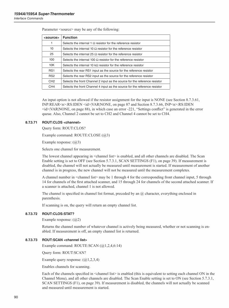
1594A/1595A Super-ThermometerInterface Commands
90
Parameter <source> may be any of the following:
<source> Function
1 Selects the internal 1 W resistor for the reference resistor
10 Selects the internal 10 W resistor for the reference resistor
25 Selects the internal 25 W resistor for the reference resistor
100 Selects the internal 100 W resistor for the reference resistor
10K Selects the internal 10 kW resistor for the reference resistor
RS1 Selects the rear RS1 input as the source for the reference resistor
RS2 Selects the rear RS2 input as the source for the reference resistor
CH2 Selects the front Channel 2 input as the source for the reference resistor
CH4 Selects the front Channel 4 input as the source for the reference resistor
An input option is not allowed if the resistor assignment for the input is NONE (see Section 8.7.3.61, INP:REAR<n>:RS:IDEN <id>|VAR|NONE, on page 87 and Section 8.7.3.66, INP<n>:RS:IDEN <id>|VAR|NONE, on page 88), in which case an error -221, “Settings conflict” is generated in the error queue. Also, Channel 2 cannot be set to CH2 and Channel 4 cannot be set to CH4.
8.7.3.71 ROUT:CLOS <channel>
Query form: ROUT:CLOS?
Example command: ROUTE:CLOSE (@3)
Example response: (@3)
Selects one channel for measurement.
The lowest channel appearing in <channel list> is enabled, and all other channels are disabled. The Scan Enable setting is set to OFF (see Section 5.7.3.1, SCAN SETTINGS (F1), on page 39). If measurement is disabled, the channel will not actually be measured until measurement is started. If measurement of another channel is in progress, the new channel will not be measured until the measurement completes.
A channel number in <channel list> may be 1 through 4 for the corresponding front channel input, 5 through 14 for channels of the first attached scanner, and 15 through 24 for channels of the second attached scanner. If a scanner is attached, channel 1 is not allowed.
The channel is specified in channel list format, preceded by an @ character, everything enclosed in parenthesis.
If scanning is on, the query will return an empty channel list.
8.7.3.72 ROUT:CLOS:STAT?
Example response: (@2)
Returns the channel number of whatever channel is actively being measured, whether or not scanning is en-abled. If measurement is off, an empty channel list is returned.
8.7.3.73 ROUT:SCAN <channel list>
Example command: ROUTE:SCAN (@1,2,4,6:14)
Query form: ROUT:SCAN?
Example query response: (@1,2,3,4)
Enables channels for scanning.
Each of the channels specified in <channel list> is enabled (this is equivalent to setting each channel ON in the Channel Menu), and all other channels are disabled. The Scan Enable setting is set to ON (see Section 5.7.3.1, SCAN SETTINGS (F1), on page 39). If measurement is disabled, the channels will not actually be scanned and measured until measurement is started.
91
Remote OperationInterface Commands
A channel number in <channel list> may be 1 through 4 for the corresponding front channel input, 5 through 14 for channels of the first attached scanner, and 15 through 24 for channels of the second attached scanner. If a scanner is attached, channel 1 will not be enabled.
A range of channels may be conveniently included in the channel list by using a colon between the channel range limits. The query response lists all enabled channels separately. If scanning is off, the query will return an empty channel list.
The *RST command enables channel 2 and disables all others.
8.7.3.74 ROUT:SCAN:ADD <channel list>
Example command: ROUTE:SCAN:ADD (@5,6,7)
Adds channels to the scan list.
Each of the channels specified in <channel list> is enabled (this is equivalent to setting each channel ON in the Channel Menu). The Scan Enable setting is set to ON (see Section 5.7.3.1, SCAN SETTINGS (F1), on page 39). If measurement is disabled, the channels will not actually be scanned and measured until measurement is started.
A channel number in <channel list> may be 1 through 4 for the corresponding front channel input, 5 through 14 for channels of the first attached scanner, and 15 through 24 for channels of the second attached scanner. If a scanner is attached, channel 1 will not be enabled.
8.7.3.75 ROUT:SCAN:ALT <boolean>
Query form: ROUT:SCAN:ALT?
Alternate parameter: DEF
Sets the scan Alternate Reference setting (see Section 5.7.3.1, SCAN SETTINGS (F1), on page 39).
The *RST command sets Alternate Reference to its default setting which is OFF.
8.7.3.76 ROUT:SCAN:DEL <channel list>
Example command: ROUTE:SCAN:DEL (@4)
Removes channels from the scan list.
Each of the channels specified in <channel list> is disabled (this is equivalent to setting each channel OFF in the Channel Menu).
8.7.3.77 ROUT:SCAN:REF <channel>
Query form: ROUT:SCAN:REF?
Example command: ROUTE:SCAN:REF 4
Sets the scan Reference Channel setting (see Section 5.7.3.1, SCAN SETTINGS (F1), on page 39).
Parameter <channel> is the front channel number to use as the reference, which may be 1 through 4 when no scanner is attached. If a scanner is attached, the channel 1 option is not available but the scanner channels are allowed, numbered 5 through 14 for the first scanner, 15 through 24 for the second. The default option is chan-nel 2. For the reference channel to be measured, it must be enabled (see command Channel Menu).
The *RST command sets Reference Channel to 2.
8.7.3.78 ROUT:SCAN:REP <value>
Example command: ROUT:SCAN:REP 10
Query form: ROUT:SCAN:REP?
Alternate parameter: DEF, MIN, MAX
Sets the scan Repeat Count setting (see Section 5.7.3.1, SCAN SETTINGS (F1), on page 39).
1594A/1595A Super-ThermometerInterface Commands
92
Parameter <value> is the number of measurements performed on a channel before advancing to the next chan-nel. The range is 1 through 100 and the default is 1.
The *RST command sets Repeat Count to 1.
8.7.3.79 ROUT:SCAN:STAT <boolean>
Query form: ROUT:SCAN:STAT?
Alternate parameter: DEF
Sets the Scan Enable setting (see Section 5.7.3.1, SCAN SETTINGS (F1), on page 39).
The *RST command sets Scan Enable to the default setting which is ON.
8.7.3.80 SENS:APER[:DISP] <time>
Query form: SENS:APER[:DISP]?
Alternate parameter: DEF, MIN, MAX
Password protection: Measure Protection
Sets the measurement or Display Interval (see Section 5.7.3.2, TIMING SETTINGS (F2), on page 39).
Parameter <time> is in seconds. Allowed values for <time> are 1, 2, 10, 30, and 60. Values other than these are rounded down to the nearest allowed value.
The Sample Period setting will be changed if necessary so that it is never greater than the Display Interval setting.
The *RST command sets Display Interval to the default setting which is 2.
8.7.3.81 SENS:APER:PRES NORM|PREC|FAST|LONG
Query form: SENS:APER:PRES?
Alternate parameter: DEF
Sets the measurement timing settings to preset values (see Section 5.7.3.2, TIMING SETTINGS (F2), on page 39). This is equivalent to pressing the PRESET NORMAL, PRESET PRECISION, PRESET FAST, or PRESET LONG function key in the Timing Settings screen. It affects the Sample Period, Display Interval, and Average Enable settings.
For the query form, if the timing settings match one of the presets, the name of the preset is returned. If the settings do not match any of the presets, “NONE” is returned.
The *RST command sets the timing settings to the default preset which is NORM.
8.7.3.82 SENS:APER:SAMP <time>
Query form: SENS:APER:SAMP?
Alternate parameter: DEF, MIN, MAX
Password protection: Measure Protection
Sets the measurement Sample Period (see Section 5.7.3.2, TIMING SETTINGS (F2), on page 39).
Parameter <time> is in seconds. Allowed values for <time> are 1, 2, 5, and 10. Values other than these are rounded down to the nearest allowed value.
The Display Interval setting will be changed if necessary so that it is never less than the Sample Period setting.
The *RST command sets Sample Period to the default setting which is 2 seconds.
8.7.3.83 SENS:AVER1[:STAT] <boolean>
Query form: SENS:AVER1?
93
Remote OperationInterface Commands
Password protection: Measure Protection
Sets the Average Enable for the sample average (see Section 5.7.3.2, TIMING SETTINGS (F2), on page 39).
The *RST command sets Average Enable to the default setting which is ON.
8.7.3.84 SENS:AVER2[:STAT] <boolean>
Query form: SENS:AVER2?
Password protection: Measure Protection
Sets the digital filter’s Filter Enable (see Section 5.7.3.3, DIGITAL FILTER (F3), on page 41).
The *RST command sets Filter Enable to the default setting which is ON.
8.7.3.85 SENS:AVER2:COUN <count>
Query form: SENS:AVER2:COUN?
Alternate parameter: DEF, MIN, MAX
Password protection: Measure Protection
Sets the digital filter’s Average Count setting (see Section 5.7.3.3, DIGITAL FILTER (F3), on page 41).
Parameter <count> is the average count. Allowed values range from 2 through 100.
This setting is only meaningful when Filter Enable is ON.
The *RST command sets Average Count to the default setting, which is 30.
8.7.3.86 SENS:AVER2:CLEA
Clears the digital filter buffer. This is equivalent to pressing the CLEAR FILTER function key in the Digital Filter screen (see Section 5.7.3.3, DIGITAL FILTER (F3), on page 41).
8.7.3.87 SENS[<n>][:FRES]:DATA?
Example command: SENS4:DATA?
Example response: 44.221571
Reads a channel’s latest resistance measurement.
Suffix <n> is the channel number: 1 through 4 for the corresponding front channel input, 5 through 14 for channels of the first attached scanner, and 15 through 24 for channels of the second attached scanner. If the suffix number is omitted, the latest measurement regardless of channel is returned.
If the Calculation setting for the channel is either RESISTANCE or TEMPERATURE (see Section 8.7.3.27, CALC<n>:TYPE TEMP|RES|RAT, on page 80), a resistance value in ohms is returned. If calculation is ratio, a resistance ratio value is returned. In either case, the returned value is obtained after processing by the digital filter.
If no measurement is available, no response is returned and error code -230, “Data corrupt or stale” is gener-ated in the error queue.
8.7.3.88 SENS[<n>]:RRAT:DATA?
Example command: SENS4:RRAT:DATA?
Example response: 1.30244715
Reads a channel’s latest resistance ratio measurement.
Suffix <n> is required, which specifies the channel number: 1 through 4 for the corresponding front channel input, 5 through 14 for channels of the first attached scanner, and 15 through 24 for channels of the second at-tached scanner. If the suffix number is omitted, the latest measurement regardless of channel is returned.

1594A/1595A Super-ThermometerInterface Commands
94
The returned value is a resistance ratio after processing by the digital filter. If no measurement is available, no response is returned and error code -230, “Data corrupt or stale” is generated in the error queue.
8.7.3.89 STAT:OPER?
Example response: 16
Reads and clears the Operation Status Event Register. This indicates whether a new measurement became available to read (using FETC?) since the previous STAT:OPER? query. The return value is 16 if a new mea-surement has been acquired and 0 otherwise. Reading the Operation Status Event Register using this command clears the register. The register is also cleared when a *CLS or FETC? command is received.
8.7.3.90 STAT:OPER:COND?
Example response: 16
Reads the Operation Status Condition Register. This indicates whether or not measurement is enabled. The return value is 16 if measurement is enabledand 0 otherwise. Reading the Operation Status Condition Register does not change it.
8.7.3.91 STAT:OPER:ENAB <value>
Example command: STAT:OPER:ENAB 16
Query form: STAT:OPER:ENAB?
Alternate parameter: DEF
Sets the Operation Status Enable Register. This mask register determines which corresponding bits of the Op-eration Status Event Register affect the Operation Status Bit (OSB, bit 7) of the Status Byte Register. A value of 16 enables reporting when a new measurement is acquired. The default setting is 0.
8.7.3.92 STAT:QUES?
Example response: 16
Reads and clears the Questionable Status Event Register. This indicates whether a new measurement that was erroneous or questionable was acquired since the previous STAT:QUES? query.
The bits in the Questionable Status Event Register correspond to the bits in the Questionable Status Condition Register and are caused by the same conditions (see Section 8.7.3.93, STAT:QUES:COND?, on page 94). The difference is the bits in the Questionable Status Event Register remain set after the condition no longer ex-ists. Reading the Questionable Status Event Register using the STAT:QUES? command clears the register. The register is also cleared when a *CLS command is received.
8.7.3.93 STAT:QUES:COND?
Example response: 16
Reads the Questionable Status Condition Register. This indicates whether the latest measurement was errone-ous or questionable.
The return value is 16 if the latest measurement is questionable and 0 otherwise. The Questionable Status Condition Register is cleared when a new valid measurement is acquired. Reading the Questionable Status Condition Register does not change it.
8.7.3.94 STAT:QUES:ENAB <value>
Example command: STAT:QUES:ENAB 16
Query form: STAT:QUES:ENAB?
Alternate parameter: DEF
Sets the Questionable Status Enable Register. This mask register determines which corresponding bits of the Questionable Status Event Register affect the Questionable Status Bit (QSB, bit 3) of the Status Byte Register. A value of 16 enables reporting of questionable measurements. The default setting is 0.
95
Remote OperationInterface Commands
8.7.3.95 SYST:BEEP[:IMM]
Example command: SYST:BEEP
Produces an immediate beep from the speaker.
8.7.3.96 SYST:BEEP:KEY <boolean>
Query form: SYST:KEY:BEEP?
Alternate parameter: DEF
Sets the Key Beep setting (see Section 5.7.4.1, USER SETTINGS (F1), on page 47). The default setting is ON.
8.7.3.97 SYST:BEEP:ALER <boolean>
Query form: SYST:KEY:ALER?
Alternate parameter: DEF
Sets the Alert Beep setting (see Section 5.7.4.1, USER SETTINGS (F1), on page 47). The default setting is ON.
8.7.3.98 SYST:CODE:VERS?
Example response: 1.23,1.00,1.10
Reads the firmware code version numbers. The response contains the following:
<UI version>,<kernel version>,<analog version>
8.7.3.99 SYST:COMM:GPIB:ADDR <value>
Query form: SYST:COMM:GPIB:ADDR?
Alternate parameter: DEF, MIN, MAX
Sets the IEEE-488 port’s Address setting (see Section 8.6, Configuring the IEEE-488 Port, on page 69).
8.7.3.100 SYST:COMM:GPIB[:STAT] <boolean>
Query form: SYST:COMM:GPIB?
Sets the IEEE-488 port’s Port Enable setting (see Section 8.6, Configuring the IEEE-488 Port, on page 69).
8.7.3.101 SYST:COMM:GPIB:TERM LIN|RET
Query form: SYST:COMM:GPIB:TERM?
Sets the IEEE-488 port’s Termination setting (see Section 8.6, Configuring the IEEE-488 Port, on page 69).
8.7.3.102 SYST:COMM:SER:BAUD <value>
Query form: SYST:COMM:SER:BAUD?
Sets the serial port Baud Rate setting (see Section 8.5, Configuring the RS-232 Serial Port, on page 69).
8.7.3.103 SYST:COMM:SER:LIN <boolean>
Query form: SYST:COMM:SER:LIN?
Alternate parameter: DEF
Sets the serial port’s Linefeed setting (see Section 8.5, Configuring the RS-232 Serial Port, on page 69).
8.7.3.104 SYST:COMM:SOCK:ADDR <IP address>
Example command: SYST:COMM:SOCK:ADDR “147.120.0.11”
Query form: SYST:COMM:SOCK:ADDR?
1594A/1595A Super-ThermometerInterface Commands
96
Sets the network port’s IP Address setting (see Section 8.2, Configuring the Network (LAN) Port, on page 65).
Parameter <IP address> is a string specifying the address using IP dot notation.
This setting is only allowed when DHCP is OFF.
The query form returns the static IP address when DHCP is OFF and returns the dynamically assigned IP ad-dress when DHCP is ON.
8.7.3.105 SYST:COMM:SOCK:CONT OFF|ON|QUER
Query form: SYST:COMM:SOCK:CONT?
Sets the network port’s Control Enable setting. This determines whether the instrument accepts control com-mands received via the network port.
Allowed parameter values are OFF, ON, and QUER. When the setting is OFF the network port cannot be used to control the instrument, and all commands are ignored. When the setting is ON commands may be used to control and operate the instrument. When the setting is QUER, commands that read settings and data are al-lowed, but commands that change settings are ignored. The default setting is QUER.
8.7.3.106 SYST:COMM:SOCK:DHCP <boolean>
Query form: SYST:COMM:SOCK:DHCP?
Sets the network port’s DHCP Enable setting (see Section 8.2, Configuring the Network (LAN) Port, on page 65).
8.7.3.107 SYST:COMM:SOCK:GAT <IP address>
Example command: SYST:COMM:SOCK:GAT “147.120.0.1”
Query form: SYST:COMM:SOCK:GAT?
Sets the network port’s Gateway setting (see Section 8.2, Configuring the Network (LAN) Port, on page 65).
Parameter <IP address> is a string specifying the address of the gateway server, using IP dot notation.
This setting is only meaningful when DHCP is OFF.
The query form returns the value of the Gateway setting when DHCP is OFF and returns the dynamically provided gateway address when DHCP is ON.
8.7.3.108 SYST:COMM:SOCK:KEEP <seconds>
Example command: SYST:COMM:SOCK:KEEP 3600
Query form: SYST:COMM:SOCK:KEEP?
Alternate parameter: DEF, MIN, MAX
Sets the network port’s keep-alive timeout setting.
Parameter <seconds> is the keep-alive timeout value, in seconds.
This setting determines the length of time, in seconds, after which the socket is automatically closed if there is no activity. At power-on the setting defaults to 60 seconds. If a different timeout is desired, the settings can be changed using this command. If the setting is set to 0, the keep-alive timeout will be disabled.
The keep-alive timeout may be useful if a connection is dropped unexpectedly, such as if the network or cli-ent fails. The network socket of the Super-Thermometer might otherwise remain open indefinately, and no subsequent socket connection request would be accepted. With the keep-alive timeout enabled, if no activity is detected during the timeout period, the socket will close automatically, and a new connection will then be accepted.
In applications where there might normally be a long period between messages, it might be necessary to in-crease or disable the keep-alive timeout to prevent the connection from being closed automatically.
97
Remote OperationInterface Commands
8.7.3.109 SYST:COMM:SOCK:MAC?
Example response: “00204A9AF1A2”
Reads the network port’s Hardware MAC address (see Section 8.2, Configuring the Network (LAN) Port, on page 65).
8.7.3.110 SYST:COMM:SOCK:MASK <IP address>
Example command: SYST:COMM:SOCK:MASK “255.255.255.0”
Query form: SYST:COMM:SOCK:MASK?
Sets the network port’s Subnet Mask setting (see Section 8.2, Configuring the Network (LAN) Port, on page 65).
Parameter <IP address> is a string specifying the subnet mask, using IP dot notation.
This setting is only meaningful when DHCP is OFF.
The query form returns the value of the Subnet Mask setting when DHCP is OFF and returns the dynamically provided subnet mask when DHCP is ON.
8.7.3.111 SYST:COMM:SOCK:NAME <name>
Example command: SYST:COMM:SOCK:NAME “MY-1595A”
Query form: SYST:COMM:SOCK:NAME?
Alternate parameter: DEF
Sets the network port’s Host Name setting (see Section 8.2, Configuring the Network (LAN) Port, on page 65).
Parameter <name> is a string specifying the Host Name. The string may contain upper-case letters, numerals, and underscores and may be up to 24 characters in length. Issuing the command with parameter “DEF” sets the Host Name to the default value, which is “FLUKE-159X-<serial number>”.
8.7.3.112 SYST:COMM:USB[:STAT] <boolean>
Query form: SYST:COMM:USB?
Sets the USB port’s Port Enable setting (see Section 8.4, Configuring the USB Port, on page 68).
8.7.3.113 SYST:CONF:CHAN?
Example response: 4
Reads the number of available channels. The Super-Thermometer by itself has 4 available channels. If one optional scanner is attached, the number of available channels with be 14. If two optional scanners are at-tached, the number of available channels will be 24. (Channel 1 is counted even though it is not enabled when a scanner is attached.)
8.7.3.114 SYST:CONF:SCAN?
Example response: “2590”
Reads the model number of an attached scanner. The model number is enclosed in quotation characters. If no scanner is attached, the response is an empty string enclosed in quotation characters.
8.7.3.115 SYST:DATE <year>,<month>,<day>
Query form: SYST:DATE?
Example query response: 2009,12,31
Password protection: Time/Date Protection
Sets the Date of the system clock.
1594A/1595A Super-ThermometerInterface Commands
98
8.7.3.116 SYST:ERR?
Example response: -100,“Command error”
Reads the next error in the error queue. When an error is read it is removed from the error queue, and the next error may be read by sending the command again. If there are no more errors, the response is 0,“No error”. The error queue holds ten errors. If the error queue is already full when a new error is generated, the last error in the error queue is replaced with the error, -350,“Queue overflow”. The error queue may be cleared using the command *CLS. Possible errors are listed in the following table.
Error Cause
0,“No error” The error queue is empty.
-100,“Command error” An unrecognized command was received.
-109,“Missing parameter” A required parameter was missing.
-114,“Header suffix out of range” A suffix number was out of range. (This may occur if a channel does not exist because the scanner is not attached.)
-130,“Suffix error” A required suffix number is missing.
-200,“Execution error” A command could not be executed.
-203,“Command protected” A command could not be executed because a setting is password protected.
-220,“Parameter error” A command could not be executed because one or more parameters are out of range or invalid.
-221,“Settings conflict” A command could not be executed in the current state of the instrument.
-222,“Data out of range” A command could not be executed because a parameter was out of range, of the wrong type, or not recognized.
-224,“Illegal parameter value” A command could not be executed because a parameter was not an allowed option.
-230,“Data corrupt or stale” A response could not be returned because valid data is not available.
-330,“Self-test failed” A self-test failed because of a hardware error.
-350,“Queue overflow” An error occurred when the error queue was full.
-360,“Communication error” A communication error occurred, such as a framing error or input buffer overrun.
-400,“Query error” A response to a query was not transmitted prior to another command being received.
8.7.3.117 SYST:KLOC <boolean>
Query form: SYST:KLOC?
Alternate parameter: DEF
Sets the front-panel key lock.
If the parameter is 1, front-panel keys are inoperable. The key lock remains on until the command is sent with the parameter 0.
The key lock setting is initially off at power-on. The *RST command sets key lock off.
8.7.3.118 SYST:PASS:CDIS
Disables access to password-protected settings. The SYST:PASS:CEN command may be used subsequently to enable access.
8.7.3.119 SYST:PASS:CEN <password>
Example command: SYST:PASS:CEN 1234
Enables access to password-protected settings. If <password> is incorrect, error -221,“Settings conflict” is generated in the error queue. Password access remains enabled until the SYST:PASS:CDIS command is re-ceived. Password access is disabled at power-on.
99
Remote OperationInterface Commands
8.7.3.120 SYST:PASS:CEN:STAT?
Returns the password-access state. The response is 0 if access is disabled and 1 if access is enabled.
8.7.3.121 SYST:PASS:GROU:MEAS <boolean>
Query form: SYST:PASS:GROU:MEAS?
Password protection: unconditional
Alternate parameter: DEF
Sets the password Measure Protection setting (see Section 5.7.7.1, PASSWORD (F4), on page 54). When Measure Protection is on, settings related to measurement, and their associated commands, are protected.
8.7.3.122 SYST:PASS:GROU:PROB <boolean>
Query form: SYST:PASS:GROU:PROB?
Password protection: unconditional
Alternate parameter: DEF
Sets the password Probe Protection setting (see Section 5.7.7.1, PASSWORD (F4), on page 54). When Probe Protection is on, settings related to probe definition, and their associated commands, are protected.
8.7.3.123 SYST:PASS:GROU:RES <boolean>
Query form: SYST:PASS:GROU:RES?
Password protection: unconditional
Alternate parameter: DEF
Sets the password Resistor Protection setting (see Section 5.7.7.1, PASSWORD (F4), on page 54). When Resistor Protection is on, settings related to resistor definition, and their associated commands, are protected.
8.7.3.124 SYST:PASS:GROU:TIME <boolean>
Query form: SYST:PASS:GROU:TIME?
Password protection: unconditional
Alternate parameter: DEF
Sets the password Time/Date Protection setting (see Section 5.7.7.1, PASSWORD (F4), on page 54). When Time/Date Protection is on, setting the time and date is protected.
8.7.3.125 SYST:PASS:NEW <current password>,<new password>
Example command: SYST:PASS:NEW 1234,9999
Changes the password. If <current password> is incorrect, error -221,“Settings conflict” is generated in the error queue.
8.7.3.126 SYST:PON:MIN?
Returns the time in minutes since power on.
8.7.3.127 SYST:TIME <hour>,<minute>,<second>
Query form: SYST:TIME?
Example query response: 23,59,59
Password protection: Time/Date Protection
Sets the Time of the system clock.
8.7.3.128 SYST:TIME:DAYL OFF|NAM|EUR
Example command: SYST:TIME:DAYL NAM
1594A/1595A Super-ThermometerInterface Commands
100
Query form: SYST:TIME:DAYL?
Password protection: Time/Date Protection
Alternate parameter: DEF
Sets the Daylight Saving automatic adjust setting (see Section 5.7.5.1, TIME DATE (F1), on page 50).
Allowed parameter values are OFF for no automatic daylight saving adjustment, NAM for adjustment accord-ing to the schedule used in North America (the United States, Canada, and Mexico), and EUR for adjustment according to the schedule used in Europe. The default setting is OFF.
8.7.3.129 TEST:CURR:CONF <channel>,<current>,<polarity>
Query form: TEST:CURR:CONF?
Example query response: 2,1.0,0
Sets the configuration of the sensing current test (see Section 9, Calibration, on page 103).
Parameter <channel> may be 1 through 4, referring to front channels 1 through 4.
Parameter <current> is the driving current.
Parameter <polarity> sets the direction of the current and may be either 0 for forward or 1 for reverse.
8.7.3.130 TEST:CURR[:STAT] <boolean>
Query form: TEST:CURR?
Sets the state of the sensing current test (see Section 9, Calibration, on page 103).
Parameter <boolean> given a value of 1 starts the sensing current test if it is off. A value of 0 stops the sensing current test if it is on.
During the sensing current test a constant current is sourced at the current terminals of a channel. The channel, current magnitude, and polarity may be specified using the TEST:CURR:CONF command. While a sensing current test is in progress, the display shows the Current Test status screen. Also, the 0 bit of the Operation Status Condition Register is set while the test is in progress, and is cleared when the test is stopped.
A sensing current test is stopped if the *RST command is received.
8.7.3.131 TEST:LIN:ABOR
Cancels Ratio Self-Calibration (see Section 9, Calibration, on page 103).
Ratio Self-Calibration is also canceled if the *RST command is received.
8.7.3.132 TEST:LIN:PAR?
Example response: 0.12,0.05,-0.03,-0.02
Reads the suggested calibration Linearity C<n> parameters (see Section 9, Calibration, on page 103) result-ing from the Ratio Self-Calibration.
The response contains the following:
<C1>,<C2>,<C3>,<Zero>
A response is returned only if the Ratio Self-Calibration runs to completion. If no linearity self-test report is available, error -230,“Data corrupt or stale” is generated in the error queue.
8.7.3.133 TEST:LIN:INIT
Query form: TEST:LIN:INIT?
Starts Ratio Self-Calibration (see Section 9, Calibration, on page 103).
If Ratio Self-Calibration is already in progress, error -213, “Init ignored” is generated in the error queue. While Ratio Self-Calibration is in progress, the display shows the Ratio Calibration status screen.
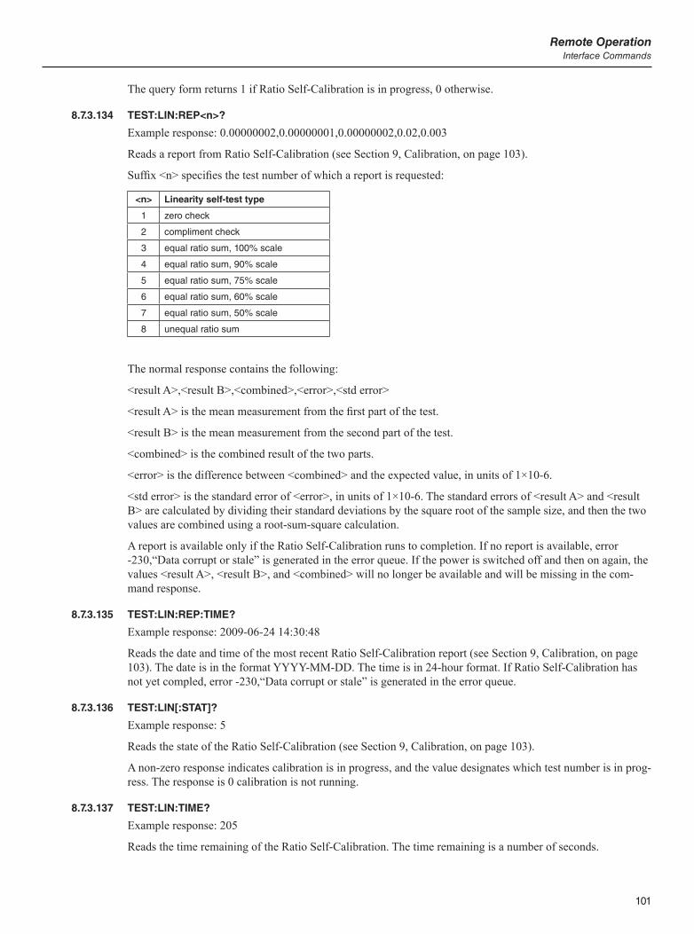
101
Remote OperationInterface Commands
The query form returns 1 if Ratio Self-Calibration is in progress, 0 otherwise.
8.7.3.134 TEST:LIN:REP<n>?
Example response: 0.00000002,0.00000001,0.00000002,0.02,0.003
Reads a report from Ratio Self-Calibration (see Section 9, Calibration, on page 103).
Suffix <n> specifies the test number of which a report is requested:
<n> Linearity self-test type
1 zero check
2 compliment check
3 equal ratio sum, 100% scale
4 equal ratio sum, 90% scale
5 equal ratio sum, 75% scale
6 equal ratio sum, 60% scale
7 equal ratio sum, 50% scale
8 unequal ratio sum
The normal response contains the following:
<result A>,<result B>,<combined>,<error>,<std error>
<result A> is the mean measurement from the first part of the test.
<result B> is the mean measurement from the second part of the test.
<combined> is the combined result of the two parts.
<error> is the difference between <combined> and the expected value, in units of 1×10⁻⁶.
<std error> is the standard error of <error>, in units of 1×10⁻⁶. The standard errors of <result A> and <result B> are calculated by dividing their standard deviations by the square root of the sample size, and then the two values are combined using a root-sum-square calculation.
A report is available only if the Ratio Self-Calibration runs to completion. If no report is available, error -230,“Data corrupt or stale” is generated in the error queue. If the power is switched off and then on again, the values <result A>, <result B>, and <combined> will no longer be available and will be missing in the com-mand response.
8.7.3.135 TEST:LIN:REP:TIME?
Example response: 2009-06-24 14:30:48
Reads the date and time of the most recent Ratio Self-Calibration report (see Section 9, Calibration, on page 103). The date is in the format YYYY-MM-DD. The time is in 24-hour format. If Ratio Self-Calibration has not yet compled, error -230,“Data corrupt or stale” is generated in the error queue.
8.7.3.136 TEST:LIN[:STAT]?
Example response: 5
Reads the state of the Ratio Self-Calibration (see Section 9, Calibration, on page 103).
A non-zero response indicates calibration is in progress, and the value designates which test number is in prog-ress. The response is 0 calibration is not running.
8.7.3.137 TEST:LIN:TIME?
Example response: 205
Reads the time remaining of the Ratio Self-Calibration. The time remaining is a number of seconds.
1594A/1595A Super-ThermometerInterface Commands
102
8.7.3.138 TEST:LIN:TOL<n>?
Example response: 0.8
Reads a Ratio Self-Calibration test tolerance (see Section 9, Calibration, on page 103).
Suffix <n> specifies the test number of which the error tolerance is requested (see Section 8.7.3.134, TEST:LIN:REP<n>?, on page 101).
The response has units of 1×10⁻⁶.
8.7.3.139 TEST:SYST:ABOR
Cancels a system self-test (see Section 9, Calibration, on page 103).
A system self-test is also canceled if the *RST command is received.
8.7.3.140 TEST:SYST:INIT
Starts a system self-test (see Section 9.2, SYSTEM TEST (F1), on page 103).
If a system self-test is already in progress, error -213, “Init ignored” is generated in the error queue. While a system self-test is in progress, the display shows the System Test status screen. Also, the 0 bit of the Operation Status Condition Register is set while the test is in progress, and is cleared when the test ends or is aborted.
8.7.3.141 TEST:SYST:REP[<n>]?
Example response: 0
Reads the report from a system self-test.
Parameter <n>, when given a value of 1 or omitted, specifies the report from the power-on system self-test. A value of 2 specifies the report from the latest system self-test if one was performed subsequent to the power-on system self-test and a system self-test is not in progress. A report only becomes available if the system self-test runs to completion. If no report is available, error -230,“Data corrupt or stale” is generated in the error queue.
The response is 0 if no errors occurred.
8.7.3.142 TEST:SYST:STAT?
Example response: 1
Reads the state of the system self-test (see Section 9.2, SYSTEM TEST (F1), on page 103).
A response of 1 indicates a test is in progress, 0 otherwise.
8.7.3.143 UNIT:TEMP C|K|F
Example command: UNIT:TEMP C
Query form: UNIT:TEMP?
Alternate parameter: DEF
Sets the temperature Unit (see section Unit). The option F (Fahrenheit) will not be available if The SI Unit Lock setting is ON (see Section 9.6, CALIBRATION PARAMETERS (F5), on page 108).
The *RST command sets Unit to the default setting which is C.
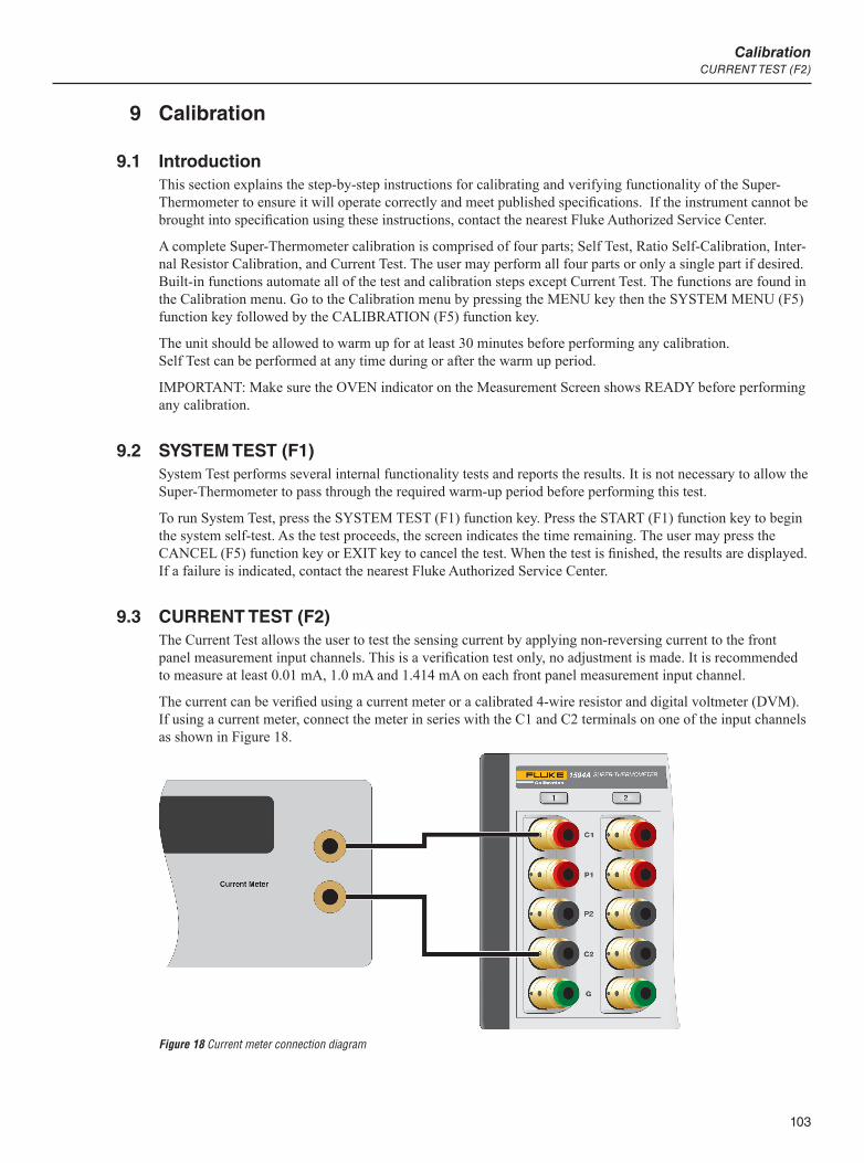
103
CalibrationCURRENT TEST (F2)
9 Calibration
9.1 IntroductionThis section explains the step-by-step instructions for calibrating and verifying functionality of the Super-Thermometer to ensure it will operate correctly and meet published specifications. If the instrument cannot be brought into specification using these instructions, contact the nearest Fluke Authorized Service Center.
A complete Super-Thermometer calibration is comprised of four parts; Self Test, Ratio Self-Calibration, Inter-nal Resistor Calibration, and Current Test. The user may perform all four parts or only a single part if desired. Built-in functions automate all of the test and calibration steps except Current Test. The functions are found in the Calibration menu. Go to the Calibration menu by pressing the MENU key then the SYSTEM MENU (F5) function key followed by the CALIBRATION (F5) function key.
The unit should be allowed to warm up for at least 30 minutes before performing any calibration. Self Test can be performed at any time during or after the warm up period.
IMPORTANT: Make sure the OVEN indicator on the Measurement Screen shows READY before performing any calibration.
9.2 SYSTEM TEST (F1)System Test performs several internal functionality tests and reports the results. It is not necessary to allow the Super-Thermometer to pass through the required warm-up period before performing this test.
To run System Test, press the SYSTEM TEST (F1) function key. Press the START (F1) function key to begin the system self-test. As the test proceeds, the screen indicates the time remaining. The user may press the CANCEL (F5) function key or EXIT key to cancel the test. When the test is finished, the results are displayed. If a failure is indicated, contact the nearest Fluke Authorized Service Center.
9.3 CURRENT TEST (F2)The Current Test allows the user to test the sensing current by applying non-reversing current to the front panel measurement input channels. This is a verification test only, no adjustment is made. It is recommended to measure at least 0.01 mA, 1.0 mA and 1.414 mA on each front panel measurement input channel.
The current can be verified using a current meter or a calibrated 4-wire resistor and digital voltmeter (DVM). If using a current meter, connect the meter in series with the C1 and C2 terminals on one of the input channels as shown in Figure 18.
Figure 18 Current meter connection diagram

1594A/1595A Super-ThermometerRATIO CALIBRATION (F3)
104
If using a calibrated resistor, connect the resistor to all four terminals on one of the front panel measurement inputs and connect the voltmeter to the P1 and P2 terminals. Refer to Table 20 for recommended resistance values. The accuracy of the DVM should be better than 0.05 % over the range of 0.02 V to 0.2 V.
Table 20 Recommended Resistors For Testing The Current
Current Resistor
0.001 mA to 0.02 mA 10 kW
0.02 mA to 0.2 mA 1 kW
0.2 mA to 2.0 mA 100W
2.0 mA to 20.0 mA 10 W
To start the test, press the CURRENT TEST (F2) function key located in the Calibration menu. The following fields are used to configure each step of the test.
CHANNEL - the input channel being tested
CURRENT - the sensing current value
POLARITY - specifies the direction of the sensing current, either forward or reverse
Select the START (F1) function key to begin the current test. Constant current is applied to the specified chan-nel allowing current measurements to be measured by the current meter or voltage readings to be taken across the resistor. During current test, the channel’s LED indicator is illuminated green. The channel, current, and polarity may be changed during the test.
Current Test is stopped by pressing the STOP (F1) function key or the EXIT key. This switches off the sensing current allowing the user to connect a different resistor or change any of the configuration fields. Press the EXIT key to leave the test screen.
If using the calibrated resistor and voltmeter method, calculate the actual current by dividing the measured voltage by the value of the resistor. The difference between the actual measured current and the current setting should be within the measurement current accuracy. If the current is not within specification, contact the near-est Fluke Authorized Service Center for more information.
9.4 RATIO CALIBRATION (F3)The Ratio Self-Calibration function allows the user to perform a ratio linearity check or calibration using an internal resistor network. No other test equipment is required. Due to the simplicity and short time the test takes to run, Ratio Self-Calibration can be performed as often as needed.
Caution: Ratio Self-Calibration does not test resistance accuracy or calibrate the internal reference resistors.
Running the Ratio Self-Calibration function does not require a password. This is because it reports the results of the linearity test only. If adjustment is needed, the Adjust Parameters function is used. This function re-quires a password because it will adjust internal calibration constants.
The START (F1) function key begins the Ratio Self-Calibration. As the test proceeds, the screen reports the results of each part of the test. The user may press the CANCEL (F5) function key or EXIT key to cancel the test.
The following is a description of each segment of Ratio Self-Calibration:
Test 1 (Zero) - This test evaluates offset errors at a resistance ratio of 0. A 0 W resistor is internally connected as Rx, and a 100 W resistor is connected as Rs. The test is performed twice, the measurements reported as re-sult A and result B. The combined result is an average of the two. Ideally the measured resistance ratio would be exactly 0.0. The reported error is the difference of the combined result from 0.0, in units of 1×10⁻⁶.
Test 2 (Complement) - This test evaluates scale errors at a resistance ratio near 1. The test has two parts. For the first part, a 100 W resistor is internally connected as Rx, and another 100 W resistor is connected as Rs. The first measured resistance ratio is reported as result A. For the second part, the two resistors are exchanged. The second measured resistance ratio is reported as result B. The combined result is the product of the two mea-

105
CalibrationRATIO CALIBRATION (F3)
sured resistance ratios. Ideally the product would be exactly 1.0. The reported error is half the difference of the combined result from 1.0, in units of 1×10⁻⁶.
Test 3 (Equal ratio sum--100% scale) - This test evaluates linearity errors at a resistance ratio near 0.5 with the measurement circuit operating at full scale. The test has two parts. For the first part, one resistor of a 100 W + 100 W resistor network is connected as Rx, and the series combination of the two resistors is connected as Rs internally. The first measured resistance ratio is reported as result A. For the second part, the opposite of the two resistors is connected as Rx and again, the series combination is connected as Rs. The second measured resistance ratio is reported as result B. Ideally the sum of the two measured resistance ratios would be exactly 1.0. The reported error is the difference of the sum from 1.0, in units of 1×10⁻⁶.
Test 4 (Equal ratio sum--90% scale) - This test evaluates linearity errors at a resistance ratio near 0.5 with the measurement circuit operating at 90% of full scale. The test is performed in the same way as Test 3, except the measurement circuit gain is reduced so that the circuit operates at the reduced scale. The reported error is the difference of the sum from 1.0, in units of 1×10⁻⁶.
Test 5 (Equal ratio sum--75% scale) - This test evaluates linearity errors at a resistance ratio near 0.5 with the measurement circuit operating at 75% of full scale. The test is performed in the same way as Test 3, except the measurement circuit gain is reduced so that the circuit operates at the reduced scale. The reported error is the difference of the sum from 1.0, in units of 1×10⁻⁶.
Test 6 (Equal ratio sum--60% scale) - This test evaluates linearity errors at a resistance ratio near 0.5 with the measurement circuit operating at 60% of full scale. The test is performed in the same way as Test 3, except the measurement circuit gain is reduced so that the circuit operates at the reduced scale. The reported error is the difference of the sum from 1.0, in units of 1×10⁻⁶.
Test 7 (Equal ratio sum--50% scale) - This test evaluates linearity errors at a resistance ratio near 0.5 with the measurement circuit operating at 50% of full scale. The test is performed in the same way as Test 3, except the measurement circuit gain is reduced so that the circuit operates at the reduced scale. The reported error is the difference of the sum from 1.0, in units of 1×10⁻⁶.
Test 8 (Unequal ratio sum) - This test evaluates linearity errors at resistance ratios near 0.25 and 0.75 (with the measurement circuit operating at full scale). The test is performed in the same way as Test 3, except the two resistors are 25 W and 75 W. The reported error is the difference of the combined result from 1.0, in units of 1×10⁻⁶.
All tests use a sensing current of 1.0 mA. The timing settings are temporarily set to provide measurements at two-second intervals and the digital filter is disabled. The reported measurement of each test is the mean of a set of measurements of the resistance ratio under certain conditions.
For each test a standard error of the mean is calculated and reported. This provides an estimate of the uncer-tainty of the mean of the reported error due to measurement noise. The standard error of the mean is calculated from the standard deviation (SA, SB) of parts A and B and the sample count (n) using the following equation:
SEaS Sn
A B=+
×1 10
2 26
The sample count is the number of samples comprising the result from each part of the test. The divisor a is 2 for Test 1 and Test 2, accounting for the fact that the reported error is calculated as an average from the two test parts. For the other tests a = 1.
When the Ratio Self-Calibration completes, the time and date (when the last test ended) are shown below the test results.
To view the test report screen, the user presses the VIEW REPORT (F1) function key. The report screen shows the specified tolerance, test result error, condition (the percent error relative to the tolerance), and the standard error of the test result error for each individual test. The tolerances shown are based on the 99% confidence level resistance ratio specifications found in the Specifications section.
The Ratio Self-Calibration report data are stored in internal non-volatile memory, overwriting the results of any previous Ratio Calibration. The report of the most recent Ratio Self-Calibration may be viewed at any time using the VIEW PREVIOUS (F2) function key in the Ratio Calibration screen.

1594A/1595A Super-ThermometerRESISTANCE CALIBRATION (F4)
106
The reported data of the Ratio Self-Calibration may be written to a file on a USB memory device using the WRITE FILE (F1) function key in the View Report screen (see Write File below).
The calibration parameters associated with measurement linearity may be adjusted to improve the accuracy if necessary using the ADJUST PARAMETERS (F2) function key (see Adjust Parameters below).
The following function keys are found in the View Report screen.
9.4.1 WRITE FILE (F1)
The Write File function allows the user to write the Ratio Self-Calibration report to a file on the USB memory device.
The user may change the file name by pressing the ENTER key to open the Alpha-Numeric interface and entering a file name. Once the file name is set, and after the USB memory device is inserted into the front USB port, the user presses the CONTINUE (F1) function key to proceed to write the file. The file is stored in a folder named “\159x\test”. If the file already exists, the new test results are added to the file.
The results of each individual test in a Ratio Self-Calibration are written to the file as follows:
LINEARITY,<test>,<tolerance>,<error>,<% of tol>,<SE>,<date and time>
<test> is the test number, 1 through 8
<tolerance> is the specified tolerance in units of 1×10⁻⁶
<error> is the error in units of 1×10⁻⁶
<% of tol> is the absolute value of the error divided by the tolerance, expressed in percent
<SE> is the standard error of the test result error in units of 1×10⁻⁶
<date and time> is the date and time of the test. The date is in the format YYYY-MM-DD. The time is in 24-hour format.
9.4.2 ADJUST PARAMETERS (F2)
The Adjust Parameters function allows the user to update the linearity parameters (LINEARITY C1, LINEAR-ITY C2, LINEARITY C3, and LINEARITY C4) to correct error observed during the Ratio Self-Calibration.
The Adjust Parameters function is always password protected. The user will be prompted to enter the correct password to continue.
The screen shows the previous values of the calibration parameters and proposed new values based on calcula-tions using the Ratio Calibration test results. The user presses YES (F4) to change the values of the linearity parameters in memory. The user may press the NO (F5) function key or the EXIT key to cancel the change.
When completed, the linearity calibration parameters will be automatically adjusted to correct for the er-rors observed during the Ratio Self-Calibration. The linearity parameters may be viewed in the Calibration Parameters screen (see Calibration Parameters section). Ratio Self-Calibration should be repeated to verify the calibration.
9.5 RESISTANCE CALIBRATION (F4)The Resistance Calibration function allows the user to test and calibrate each of the internal reference resis-tors. It requires a calibrated standard resistor of approximately the same resistance as the internal resistor that will be calibrated.
No password is required to run Resistance Calibration since it first measures an internal resistor without mak-ing any adjustment to its internal calibration parameter. After an internal resistor is measured, the results are displayed allowing the user to observe the results and decide if an adjustment is necessary.
Resistance Calibration works by measuring an internal resistor against a calibrated standard resistor. The inter-nal resistor’s calibration parameter is adjusted to correct for error.
107
CalibrationRESISTANCE CALIBRATION (F4)
To properly calibrate a Super-Thermometer internal resistor, the expanded uncertainty (k = 2) of the standard resistor should be no greater than 25% of the 95% confidence level, 1-Year Absolute Resistance Accuracy specifications. Its resistance should be approximately the same as that of the internal reference resistor being calibrated, which will result in the least measurement noise and best test uncertainty. The standard resistor may be connected to any one of the four front-panel measurement channels.
To set up the resistance calibration, the user must configure the following fields displayed in the Resistance Calibration screen:
RESISTOR - specifies the internal reference resistor to be measured
CHANNEL - is the front channel input to which the standard resistor is connected.
STANDARD RESISTANCE - is the calibrated resistance value of the standard resistor.
The START (F1) function key begins the resistance calibration. As the test proceeds, the screen indicates the status of the process. The user may press the CANCEL (F5) function key or EXIT key to cancel the test.
The resistance calibration uses the sensing current for which the resistor’s Absolute Resistance Uncertainty is specified. During the resistance calibration the digital filter is disabled and the timing is set to the Precision settings so that results will be consistent and accurate. Normal temperature measurement and data recording is suspended. Settings are automatically restored after the test. The reported measurement is the mean of a series of samples of the resistance acquired over a period of about 1 min.
When the measurement is completed, the screen shows the results, which includes the following:
MEASUREMENT - is the measured resistance of the standard resistor. This may be compared to the calibrat-ed resistance of the standard resistor to provide an indication of the accuracy of the internal reference resistor.
ABSOLUTE ERROR - is the difference between the measurement and the Standard Resistance value, pre-sented in ohms.
RELATIVE ERROR - is the difference between the measurement and the Standard Resistance value, divided by the Standard Resistance and multiplied by a factor of one million to produce a value in parts per million (ppm).
STANDARD ERROR - is the standard deviation of the samples comprising the measurement, divided by the square root of the number of samples. This provides an estimate of the standard uncertainty of the mea-surement mean due to measurement noise. It does not include uncertainty of the calibrated resistance of the standard resistor.
TIME - is the time at which the test ended, taken from the system clock. It is in 24 hour format.
DATE - is the date on which the test ended, taken from the system clock. It is in the format specified by the Date Format setting in the User Settings screen.
Tolerances for the reported error, which are required for assessing pass or fail conditions, may be found in the Absolute Resistance Uncertainty section of the Specifications section.
The results of the resistance calibration may be written to a file on a USB memory device using the WRITE FILE (F1) function key as explained below.
The calibration parameter associated with the calibrated internal reference resistor may be adjusted to improve the accuracy of the resistor using the ADJUST RESISTOR (F2) function key as explained below.
9.5.1 WRITE FILE (F1)
The Write File function allows the user to write the results of the resistance calibration to a file on the USB memory device.
The user may change the file name by pressing the ENTER key and using the Alpha-Numeric Interface. Once the file name is set, and after the USB memory device is inserted into the front USB port, the user presses the CONTINUE function key to proceed to write the file. The file is stored in a folder named “\159x\test”. If the file already exists, the new test results are added to the file.
1594A/1595A Super-ThermometerCALIBRATION PARAMETERS (F5)
108
The results of the resistance calibration are written to the file as follows:
RESISTANCE,<Rs>,<chan>,<standard>,<measurement>,<error>,<SE>,<date and time>
<Rs> is the nominal resistance of the internal reference resistor (in W).
<chan> is the channel number to which the standard resistor was connected.
<standard> is the calibrated resistance of the standard resistor.
<measurement> is the measured resistance of the standard resistor.
<error> is the error of the measurement compared to the calibrated resistance of the standard resistor, in units of ohms.
<SE> is the standard error of the reported error, in units of ohms.
<date and time> is the date and time of the test. The date is in the format YYYY-MM-DD. The time is in 24-hour format.
9.5.2 ADJUST RESISTOR (F2)
The Adjust Resistor function allows the user to apply an adjustment to an internal reference resistor’s calibra-tion parameter to improve its accuracy based on the results of the resistance calibration.
The Adjust Resistor function is always password protected. The user will be prompted to enter the correct password to continue.
The Adjust Resistor screen shows the resistor that will be adjusted, the prior value of its calibration parameter, and the new value of the calibration parameter. The user presses YES (F4) to change the calibration parameter. The user may press the NO (F5) function key or the EXIT key to cancel the change.
When the calibration parameter is updated, the Calibration Date setting is also updated to the present date (see Calibration Parameters in the Menus and Screens section). This can be overwritten by manually entering a date and pressing the EXIT key to save the value.
9.6 CALIBRATION PARAMETERS (F5)The calibration parameters may be viewed or adjusted by pressing the Calibration Parameters (F5) function key. If a password is not entered, the user will be allowed to only view the parameters. Adjustment cannot take place unless a password is entered. It is recommended to only adjust the calibration parameters as part of the previously described calibration functions. Failure to enter the calibration parameters correctly will cause the Super-Thermometer to measure with error.
If it is required to manually adjust the calibration parameters, press the ENTER key to save each change.
See the Ratio Calibration and Resistance Calibration sections for more information on the resistance calibra-tion parameters and linearity calibration parameters.
The SI UNIT LOCK setting is used to enable or disable °F as an allowed temperature unit option. When this is set to ON, temperatures may be displayed in units of °C and K only, and °F will not be available as an option for the Unit setting (see System Menu, Temperature Unit, in the Menus and Screens section)
9.6.1 Calibration Interval
Ratio Self-Calibration can be performed as often as needed to ensure proper ratio performance. Since no ad-ditional equipment is needed for Ratio Self-Calibration, it can be performed at the user’s convenience, as often as necessary. Minimally, it should be checked every 6 months during the first year of use and an alignment performed as needed.
Internal Resistor Calibration should be performed on a 6-month interval during the first year of use. After the first year, a 12-month interval is recommended.

109
CalibrationCALIBRATION PARAMETERS (F5)
9.6.2 Standby Current Check
It may be necessary to check standby current to ensure proper operation. The standby current must be manu-ally checked. Each channel’s standby current can be checked with the following steps.
NOTE: If a scanner is connected, channel 1 will not be available to test. Power off the Super-Thermometer and disconnect the scanner in order to test standby current on channel 1.
1. Connect a 100 W resistor to channel 1.
2. Press the SETUP key and disable all other channels except channel 4.
3. Highlight Channel 1 and press CHANNEL SETTINGS (F2). Set REFERENCE RESISTOR to 100 W. Set SENSING CURRENT to 1.0 mA. Set STANDBY CURRENT to ON.
4. Press and hold the EXIT key to return to the Measurement screen. Select the START MEASUREMENT (F1) function key. The Channel Select Key should be amber above channel 1 and green above channel 4. The amber color indicates the channel is in the standby current mode. The current can now be measured by inserting a current meter in series between the C1 or C2 terminal and the 100 W resistor lead. An alternative method is using a volt meter to measure the voltage drop across the 100-ohm resistor and then compute the current.
5. Calculate the difference (or error) between the actual 1.0 mA and the measured readings. Error should be less than +/- 0.05 mA.
6. Repeat steps 1 through 5 for the other channels.

111
Maintenance
10 MaintenanceAvoid operating the instrument in excessively wet, oily, dusty, or dirty environments. If the outside of the instrument becomes soiled it may be wiped clean with a damp cloth and mild detergent. DO NOT use harsh chemicals on the surface that may damage the paint or plastic.
The instrument should be handled with care. Avoid knocking, dropping, or vibrating the instrument.
This instrument is tested and calibrated at the factory. Continued regular testing and calibration is recommended.
Routinely check the ratio accuracy using the Ratio Self-Calibration function.

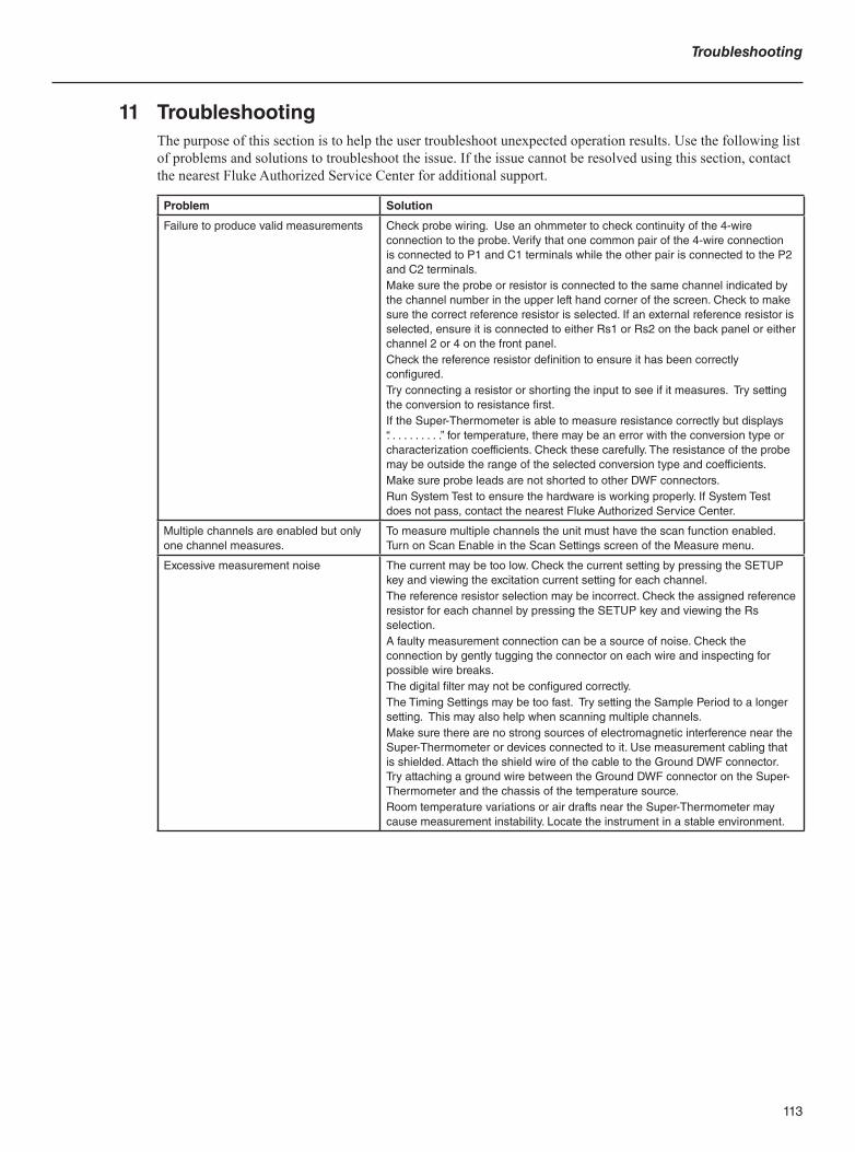
113
Troubleshooting
11 TroubleshootingThe purpose of this section is to help the user troubleshoot unexpected operation results. Use the following list of problems and solutions to troubleshoot the issue. If the issue cannot be resolved using this section, contact the nearest Fluke Authorized Service Center for additional support.
Problem Solution
Failure to produce valid measurements Check probe wiring. Use an ohmmeter to check continuity of the 4-wire connection to the probe. Verify that one common pair of the 4-wire connection is connected to P1 and C1 terminals while the other pair is connected to the P2 and C2 terminals.Make sure the probe or resistor is connected to the same channel indicated by the channel number in the upper left hand corner of the screen. Check to make sure the correct reference resistor is selected. If an external reference resistor is selected, ensure it is connected to either Rs1 or Rs2 on the back panel or either channel 2 or 4 on the front panel. Check the reference resistor definition to ensure it has been correctly configured. Try connecting a resistor or shorting the input to see if it measures. Try setting the conversion to resistance first. If the Super-Thermometer is able to measure resistance correctly but displays “. . . . . . . . . .” for temperature, there may be an error with the conversion type or characterization coefficients. Check these carefully. The resistance of the probe may be outside the range of the selected conversion type and coefficients.Make sure probe leads are not shorted to other DWF connectors.Run System Test to ensure the hardware is working properly. If System Test does not pass, contact the nearest Fluke Authorized Service Center.
Multiple channels are enabled but only one channel measures.
To measure multiple channels the unit must have the scan function enabled. Turn on Scan Enable in the Scan Settings screen of the Measure menu.
Excessive measurement noise The current may be too low. Check the current setting by pressing the SETUP key and viewing the excitation current setting for each channel. The reference resistor selection may be incorrect. Check the assigned reference resistor for each channel by pressing the SETUP key and viewing the Rs selection.A faulty measurement connection can be a source of noise. Check the connection by gently tugging the connector on each wire and inspecting for possible wire breaks. The digital filter may not be configured correctly.The Timing Settings may be too fast. Try setting the Sample Period to a longer setting. This may also help when scanning multiple channels.Make sure there are no strong sources of electromagnetic interference near the Super-Thermometer or devices connected to it. Use measurement cabling that is shielded. Attach the shield wire of the cable to the Ground DWF connector. Try attaching a ground wire between the Ground DWF connector on the Super-Thermometer and the chassis of the temperature source. Room temperature variations or air drafts near the Super-Thermometer may cause measurement instability. Locate the instrument in a stable environment.

1594A/1595A Super-Thermometer
114
Problem Solution
Poor accuracy The current may be too low causing poor signal to noise ratio or too high causing excessive self-heating. Check the current setting by pressing the SETUP key and viewing the excitation current setting for each channel. The reference resistor selection may be incorrect. Check the assigned reference resistor for each channel by pressing the SETUP key and viewing the Rs selection.The Timing Settings may be too fast. Try setting the Sample Period to a longer setting. This may also help when scanning multiple channels.The temperature conversion type or probe characterization coefficients may be in error. Check each of the probe parameters carefully. Use the Test Calculation function and compare the results with the probe’s calibration report table.Make sure probe leads are not shorted to other DWF connectors.Verify the reference resistor calibration value is entered correctly.Make sure the probe wires are properly and tightly connectedIf using extremely long measurement cables, the capacitance in the wires can affect the readings. Try setting the measurement timing parameter sample period to the longest setting to allow for the measurement to settle.Check the oven stability indicator on the Measurement screen. After 30 minutes from power up the indicator should change from SETTLING to READY. If the oven stability indicator never changes to READY, contact a Fluke Authorized Service Center. The unit could still be used with an external reference resistor since the internal oven has no affect when using external resistors.
Graph of measurements jumps or stair-steps
This is normal if the temperature being measured is increasing or decreasing faster than the digital filter is able to track. To eliminate this effect, temporarily disable the digital filter.
The display shows negative resistance. The measurement cable is not connected correctly.
The USB memory stick does not work Plug the memory stick into the front panel USB port and wait for about 10 seconds for the system to recognize the device. When recording data to the memory stick wait for the flashing read/write LED on the memory stick to stop flashing before removing it.Make sure the memory stick id formatted to Fat 32. This can be done by inserting the memory stick into a personal computer and right clicking on the drive letter of the memory stick and selecting properties. Make sure the memory stick is compatible with the Linux operating system 2.6 or greater.
Unit will not power up. Make sure the main power switch located on the back of the unit is turned onCheck the fuses in the back of the unit Check the power cord
The display is in the wrong language If the Super-Thermometer is inadvertently set to the wrong language the user can open the User Settings screen in English by pressing and releasing the ENTER key and then pressing and releasing the SETUP key. Select the correct language if necessary.
Screen is blank The screen saver may be on. Press any button to turn the screen back on.The system may be in standby. Press and release the Power Standby key on the front panel to bring the unit out of standby mode.
Keypad does not respond The keypad has been locked by a remote operation command. The keypad can be unlocked by sending the following command to unlock it. SYST:KLOC 0
Resistance statistics field is blank when measuring in ratio mode
When in ratio mode, the Super-Thermometer will not produce a resistance reading. If both measurements are required, set the Super-Thermometer to measure resistance and select ratio as one of the statistics fields.
115
Index
Symbols1.4142 30, 4310/100 Base T Ethernet 6524-hour format 502590 Scanner 20°C 50, 56, 108°F 50, 56, 108
AABSOLUTE ERROR 107Absolute Resistance Accuracy 7Accuracy
Measurement Current 7Resistance 7
AC power 9Active Channel 27ADD PROBE (F1) 34ADD RESISTOR (F1) 31ADDRESS 52, 69ADJUST PARAMETERS (F2) 106ADJUST RESISTOR (F2) 108Alert Beep 95ALERT BEEP 47, 57alert message 27, 81ALPHA 35, 86Alpha-Numeric Interface 23Alternate Reference 91ALTERNATE REFERENCE 39Applying the Specifications 9arrow keys 18, 23ASCII 70ASCII code 10 52ASSIGN PROBE (F1) 29, 61ASSIGN RESISTOR (F1) 31ASTM-E-1137 35Audio Indication 83AUDIO INDICATION 40, 44Authorized Service Centers 2AUTOMATIC CENTERING 49AUTOMATIC SCALING 49average 77Average Count 93AVERAGE COUNT 41AVERAGE ENABLE 40Averaging 39
Bbanana jacks 58bare wire 58baud rate 51, 69, 95BETA 35, 86brightness 47, 57
CC1 59C2 59CALCULATION 30Calibrating an SPRT 12calibration 103
internal resistors 106linearity 104
calibration date 76Calibration Date 50, 86, 89CALIBRATION DATE 31, 35, 56CALIBRATION (F5) 55Calibration Interval 108CALIBRATION PARAMETERS (F5) 55, 108CANCEL (F1) 45CANCEL (F5) 36CAN/CSA 22.2 No 61010.1-04, Pollution Degree 2 1carriage return 52Carry-handle Kit 15Case 15Ch2 90Ch4 90CHANNEL 44, 45, 104, 107Channel Select Key 18, 29CHANNEL SETTINGS (F2) 30, 61CHANNEL SETUP 28CHANNEL SETUP (F1) 29Chinese 15, 19, 47, 82CLEAR ERRORS (F1) 52CLEAR FILTER (F1) 41CLEAR GRAPH/CLEAR MESSAGE (F4) 28CLEAR INTERFACE (F1) 69COMBINED GRAPH 49Combining the Uncertainties 12Command Syntax 70COMPUTER 21, 65CONFIG (F3) 52Configuring an External Reference Resistor 62Connecting a Probe 58Control Enable 96CONTROL ENABLE 52Conversion 86CONVERSION 35, 40COPY PROBE (F2) 36Countdown Timer 27CURRENT 26, 104Current Test 103CURRENT TEST (F2) 55, 103CVD-ABC 35, 86CVD-ALPHA 35, 86
DData/Graph Section 27Date 50DATE 45, 48, 50, 58, 107Date Format 50, 81
1594A/1595A Super-Thermometer
116
DATE FORMAT 47, 57Daylight Saving 100DAYLIGHT SAVING 51, 58DECIMAL FORMAT 47, 57decimal point 18Decimal setting 81DEFINE RESISTOR (F2) 31DEL 23DELETE 24DELETE CONFIG (F3) 54DELETE key 18DELETE PROBE (F5) 38DELETE RESISTOR (F5) 33delta 80DELTA 35, 48, 86DELTA CHANNEL 49Delta Mode 80DELTA MODE 49Delta Offset 80DELTA OFFSET 49Depth 9DHCP 51, 65, 96DHCP ENABLE 51, 66dielectric absorption 40digital filter 93Digital Filter 41Digital Filter Description 41DIGITAL FILTER (F3) 41Dimensions 9display 47Display 19DISPLAY BRIGHTNESS 47, 57DISPLAY INTERVAL 40Display Menu 46DISPLAY MENU 29DISPLAY MENU (F4) 46dR/dT 11DRIFT 45dT/dW 11Due Date 89DUE DATE 31DVD 15dW/dT 11DWF connectors 58
EEarth Ground 22EDIT PROBE (F3) 36EDIT RESISTOR (F2) 32EN 61010-1 2nd Edition 1English 15, 19, 47, 82ENTER 18, 23EOI 52, 69ERASE DATA (F5) 43ERRORS (F5) 52Ethernet 21, 51, 65
excitation current 30EXIT 18EXP 18, 23exponential number 18Extended range test 15External Reference Resistor 62external resistor 20, 30
FFAT32 17FIELD SETTINGS (F2) 48FILE NAME 53Filter Enable 93FILTER ENABLE 41Filtering 39firmware 54, 95Firmware Version 50Fluke Corporation iiFrench 15, 19, 47, 82Front Panel 17, 19front-panel key lock 98Front Panel Keys 18Function Keys 18Fuse Rating 9Fuses 15Future Peripheral 21
GG 59GATEWAY 51Gateway Address 67, 96German 15, 19, 47, 82Getting Started 57GPIB 95Graph 49GRAPH SETTINGS (F4) 49Guard 59GUM 5
HHARDWARE MAC 51Hardware Mac Address 66Height 9Host Name 67, 97HOST NAME 52HTML 51, 65
IID 34IEC 625 21IEC-751 35IEEE-488 21, 52, 65, 69, 95IEEE-488 (F4) 52IFC 52Inspection 15Instruction Manuals 15

117
Interface Commands 70INTERNAL 53Internal Memory 41, 42Internal Resistor Calibration 108IP address 51, 66IP Address 96IP ADDRESS 51ISO Guide to the Expression of Uncertainty in Measurement 5ITS-90 9, 27, 35, 83, 86ITS-90 SUBRANGE ALERT 47, 57
JJapanese 15, 19, 47, 82
KK 50, 56, 108Key Beep 95KEYPAD BEEP 47, 58
LLAN 21, 65Language 19LANGUAGE 47, 57Language setting 82leakage 40limited 79LIMITED 49Limited mode 49linearity 6, 104LINEARITY C1 106LINEARITY C2 106LINEARITY C3 106LINEARITY C4 106LINEFEED 51, 52, 69Line Power 16line voltage 15, 22Linux 17Local Area Network 65Location Descriptor 23
MMAC address 51Main Menu 28Maintenance 111Making Measurements 61MANAGE PROBES (F5) 37MANAGE RESISTORS (F3 32Manufacturer 50maximum 78MAXIMUM 48Maximum Current 30, 86, 89MAXIMUM CURRENT 31, 35Maximum operating altitude 9MAXIMUM TEMPERATURE 35mean 77MEAN 45, 48
MEAN 1 45MEAN 2 45MEAN 3 45MEASUREMENT 107Measurement Current Accuracy 7Measurement Inputs 17measurement noise 8, 12, 40Measurement Progress Bar 27Measurement range 9Measurement Screen 25Measure Menu 38MEASURE MENU 28MEASURE PROTECTION 55MEASURE TIME 44, 63Measuring an SPRT 10Measuring a PRT 13Measuring a Temperature Probe 61Measuring a Thermistor 14Measuring Resistance Ratio 62MEMORY DEVICE 42, 53MENU 18Menu Navigation 24Menus 23Menu System 24minimum 78MINIMUM 48Model 50MOVE DOWN (F4) 33, 38MOVE UP (F3) 33, 38moving window 79Multiplexer 20
Nn 79N 48Network 51NETWORK (F3) 51Network port 51nominal current 30, 43, 86NOMINAL CURRENT 35non-volatile 41numeric keys 18
OOperating relative humidity 9operating temperature 9oven 89OVEN 27
PP1 59P2 59password 24, 99PASSWORD 54PASSWORD (F4) 54PEM 15, 22
1594A/1595A Super-Thermometer
118
PHASE 45POLARITY 104POLYNOMIAL 35, 36PORT ENABLE 51, 52, 69port number 65Power Entry Module 15Power Standby key 18PRESET FAST 92PRESET FAST (F3) 41PRESET LONG 92PRESET LONG (F4) 41PRESET NORMAL 92PRESET NORMAL (F1) 40PRESET PRECISION 92PRESET PRECISION (F2) 41PROBE 45probe definition 29, 61, 85, 86Probe Definitions 54PROBE ID 26Probe Library 29, 34, 37, 54, 61, 85, 86Probe Library Capacity 38Probe Menu 34PROBE MENU 28PROBE MENU (F2) 34PROBE PROTECTION 54PRT 34PT-100 35, 86
QQueue overflow 52
RR0 35, 86Rack Mounting 16Rack Mount Kit 15ratio 9, 39, 55, 104RATIO 30, 48Ratio Accuracy 6, 10RATIO CALIBRATION (F3) 55, 104Ratio Self-Calibration 55, 100, 101, 104, 108READ FILE (F1) 32, 37READ FILE (F3) 43READ PROBE (F4) 37READ RESISTOR (F3) 32READY 27Rear Panel 17, 20rear USB 68RECALL CONFIG (F2) 53recording 81Recording 27Recording Menu 41RECORDING MENU (F4) 41RECORDING SETTINGS (F1) 42Record Statistics 80RECORD STATISTICS 42REFERENCE CHANNEL 39
reference resistor 30, 62Reference Resistor Drift 12REFERENCE RESISTOR (Rs) 30RELATIVE ERROR 107Relative Measurement Current Accuracy 8Remote Interface 51REMOTE INTERFACE (F2) 51Remote Operation Connections 21Repeat Count 91REPEAT COUNT 39REPEAT NOMINAL 44, 63Report Operation Commands 70RESET STATISTICS (F3) 28Resistance 89RESISTANCE 30, 48Resistance Accuracy 7, 11, 13resistance calibration 106RESISTANCE CALIBRATION (F4) 55, 106Resistance Ratio Temperature 30RESISTANCE VALUE 31RESISTOR 34, 107resistor definition 31resistor definition library 31Resistor Definitions 55RESISTOR ID 31Resistor Library 55RESISTOR PROTECTION 55Resistor Stability 6RESTORE DEFAULT (F4) 54Rs 9, 27, 30RS 26Rs1 20, 62, 90Rs2 20, 62, 90RS-232 21, 65, 69Rs DUE ALERT 47, 57Rs inputs 17R(T) 87RT90 9R(T) POLYNOMIAL 36RTPW 9, 86Russian 15, 19, 47, 82Rx 9
SSafety Information 1Sample Count 49SAMPLE COUNT 49Sample Period 39, 40, 92SAMPLE PERIOD 40sample size 79Sampling 39SAVE (F2) 36Scan Enable 90SCAN ENABLE 39scan list 91Scanner 20

119
Scanner Connection 20scanning 90Scanning 62SCAN SETTINGS (F1) 39Screens 23Screen Saver 47SCREEN SAVER DELAY 47, 57SCREEN SAVER ENABLE 47, 57SDC 52self-heating 30, 43, 63SELF-HEATING 45sensing current 30, 40, 84, 103SENSING CURRENT 30, 45SENSING CURRENT 1 45SENSING CURRENT 2 45SENSING CURRENT 3 45Sensing Current Test 100SE OF MEAN 48SERIAL (F1) 51Serial Number 50serial port 21, 69SETTLE TIME 44, 63SETTLING 27SETUP key 18, 29SET UP Rs (F1 31SHOW TABLE/GRAPH (F2) 28sign key 18, 23SI Unit Lock 50SI UNIT LOCK 56, 108sliding window 49spade connectors 58Spanish 15, 19, 47, 82Specifications 5spread 79SPREAD 48standard deviation 48, 78STANDARD ERROR 45, 107standard error of the mean 48, 79STANDARD RESISTANCE 107standby 18Standby Current 30, 84STANDBY CURRENT 30Standby Current Check 109START (F1) 44START/STOP MEASUREMENT (F1) 28START/STOP RECORD (F5) 28Start-up Help 82START-UP HELP 47, 58static IP address 66Statistics 48, 49Statistics Fields 27STATISTICS MODE 49STATISTICS SETTINGS (F3) 49Status and Alert Section 27STD DEV 45, 48STD DEV 1 45
STD DEV 2 45STD DEV 3 45STEP 45stop timer 40, 84STOP TIMER ENABLE 40Storage relative humidity 9storage space 53Storage temperature 9STORE CONFIG (F1) 53Subnet Mask 67, 97SUBNET MASK 52Subrange 1 35Subrange 2 35Subrange 3 35Subrange 4 35Subrange 5 35Subrange 6 35Subrange 7 35Subrange 8 35Subrange 9 35Subrange 10 35Subrange 11 35Symbols Used 1system clock 50System Menu 50SYSTEM MENU 29SYSTEM MENU (F5) 50system self-test 102SYSTEM TEST (F1) 55, 103SYST:ERR? 52
TTCP/IP 51, 65TCP port number 5025 65TEMPERATURE 30Temperature Resolution 82TEMPERATURE RESOLUTION 47, 57temperature unit 56, 102TEMPERATURE UNIT (F5) 50Terminal Screen 68TERMINATION 52, 69TEST CALCULATION (F1) 36text field 23thermal response 40THERMISTOR 34, 36Time 50, 99TIME 45, 48, 50, 58, 107TIME DATE (F1) 50TIME/DATE PROTECTION 55Timer Beep 83TIMER DURATION 40TIME REMAINING 45TIME SPAN 49Timing 39TIMING SETTINGS (F2) 39T(R) 87
1594A/1595A Super-Thermometer
120
TRACE 50T(R) POLYNOMIAL 36TYPE 34
UUnit 56UNIT 50unlimited 79UNLIMITED 49Unlimited mode 49Unpacking 15UPDATE FIRMWARE (F5) 54USB 17, 21, 32, 41, 42, 53, 65, 81, 97
rear 68USB (F2) 51USB FILE 42User Settings 19USER SETTINGS (F1) 47User Settings Screen 57User’s Guide 15
VVARIABLE RESISTANCE 31VERTICAL CENTER 49VERTICAL SPAN 49VIEW DATA (F2) 42VIEW PREVIOUS (F2) 46
Wwarm-up period 9, 18Warnings 1Warranty iiWeb Interface 21, 68web page 52Weight 9Width 9WRITE FILE (F2) 32, 37WRITE FILE (F4) 43WT90 9
ZZero-Power 8, 13, 30, 43, 63ZERO-POWER MEASUREMENT (F5) 43ZERO-POWER RESULT 45