zynq ultrascale+ mpsoc qemu: user guide (ug1169) · zynq ultrascale+ mpsoc quick emulator user...
TRANSCRIPT
Zynq UltraScale+ MPSoC Quick Emulator User Guide
QEMU
UG1169 (v2015.4) June 23, 2016

QEMU User Guide www.xilinx.com 2UG1169 (v205.4) June 23, 2016
Revision HistoryThe following table shows the revision history for this document.
Date Version Revision
06/23/2016 2015.4 Changed the version to match PetaLinux release.
11/18/2015 1.0 Initial public release.
Send Feedback

QEMU User Guide www.xilinx.com 3UG1169 (v2015,4) June 23, 2016
UG1169 (v2015,4) June 23, 2016
Table of ContentsChapter 1: Using QEMU for Zynq UltraScale+ MPSoC
What is QEMU? . . . . . . . . . . . . . . . . . . . . . . . . . . . . . . . . . . . . . . . . . . . . . . . . . . . . . . . . . . . . . . . . . . . 4Documentation and Support Scope . . . . . . . . . . . . . . . . . . . . . . . . . . . . . . . . . . . . . . . . . . . . . . . . . . . 4
Chapter 2: Getting Started with QEMUQEMU for Zynq MPSoC Model Roadmap. . . . . . . . . . . . . . . . . . . . . . . . . . . . . . . . . . . . . . . . . . . . . . . 5Installing Petalinux. . . . . . . . . . . . . . . . . . . . . . . . . . . . . . . . . . . . . . . . . . . . . . . . . . . . . . . . . . . . . . . . . 8
Chapter 3: QEMU Quick Reference CardQuick Reference . . . . . . . . . . . . . . . . . . . . . . . . . . . . . . . . . . . . . . . . . . . . . . . . . . . . . . . . . . . . . . . . . . 10QEMU Command Line Reference Manual . . . . . . . . . . . . . . . . . . . . . . . . . . . . . . . . . . . . . . . . . . . . . 11
Chapter 4: Using XSDB with QEMUIntroduction . . . . . . . . . . . . . . . . . . . . . . . . . . . . . . . . . . . . . . . . . . . . . . . . . . . . . . . . . . . . . . . . . . . . . 33Connecting QEMU . . . . . . . . . . . . . . . . . . . . . . . . . . . . . . . . . . . . . . . . . . . . . . . . . . . . . . . . . . . . . . . . 33Limitations . . . . . . . . . . . . . . . . . . . . . . . . . . . . . . . . . . . . . . . . . . . . . . . . . . . . . . . . . . . . . . . . . . . . . . 35
Chapter 5: Creating Boot Images on QEMUIntroduction . . . . . . . . . . . . . . . . . . . . . . . . . . . . . . . . . . . . . . . . . . . . . . . . . . . . . . . . . . . . . . . . . . . . . 36Using an SD for Boot (SD Boot Tutorial) . . . . . . . . . . . . . . . . . . . . . . . . . . . . . . . . . . . . . . . . . . . . . . . 37Using QSPI for Boot . . . . . . . . . . . . . . . . . . . . . . . . . . . . . . . . . . . . . . . . . . . . . . . . . . . . . . . . . . . . . . . 38Using NAND for Boot . . . . . . . . . . . . . . . . . . . . . . . . . . . . . . . . . . . . . . . . . . . . . . . . . . . . . . . . . . . . . . 39Using TFTP for Boot . . . . . . . . . . . . . . . . . . . . . . . . . . . . . . . . . . . . . . . . . . . . . . . . . . . . . . . . . . . . . . . 40SD-Card Partitioning and Loading an Ubuntu-core File System . . . . . . . . . . . . . . . . . . . . . . . . . . . . 40
Appendix A: Additional Resources and Legal NoticesXilinx Resources . . . . . . . . . . . . . . . . . . . . . . . . . . . . . . . . . . . . . . . . . . . . . . . . . . . . . . . . . . . . . . . . . . 42Solution Centers. . . . . . . . . . . . . . . . . . . . . . . . . . . . . . . . . . . . . . . . . . . . . . . . . . . . . . . . . . . . . . . . . . 42References . . . . . . . . . . . . . . . . . . . . . . . . . . . . . . . . . . . . . . . . . . . . . . . . . . . . . . . . . . . . . . . . . . . . . . 42Please Read: Important Legal Notices . . . . . . . . . . . . . . . . . . . . . . . . . . . . . . . . . . . . . . . . . . . . . . . . 43
Send Feedback
QEMU User Guide www.xilinx.com 4UG1169 (v2015.4) June 23, 2016
Chapter 1
Using QEMU for Zynq UltraScale+ MPSoC
What is QEMU?Xilinx® provides a Quick EMUlator (QEMU) for software developers targeting the Zynq® UltraScale+™ MPSoC development platform. This system-emulation-model runs on an Intel-compatible Linux host system. To use this system emulation model you must be familiar with:
• Zynq UltraScale+ MPSoC device architecture
• GDB for remote debugging QEMU
• Generation of guest software application using Xilinx PetaLinux and SDK tools
• Device trees
This document provides the basic information to familiarize, use, and debug software with QEMU.
Documentation and Support ScopeWithin each package, Xilinx documents only those devices for which bare-metal drivers exist and have been tested.
Users might find additional device models by diving into the QEMU model itself (for example, using the info mtree command on the QEMU Console.)
Send Feedback
Chapter 2
Getting Started with QEMU
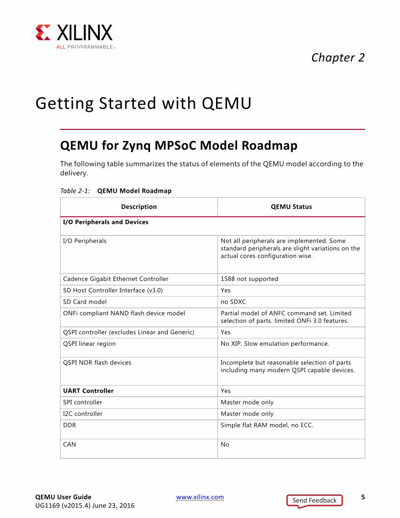
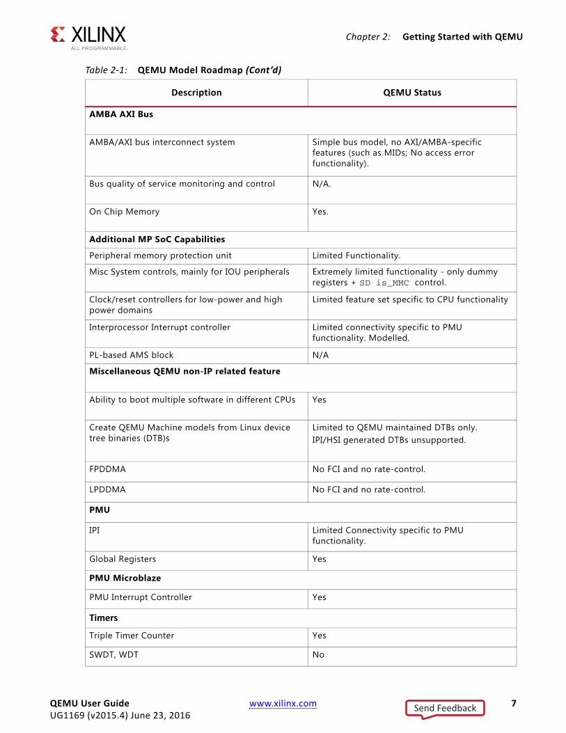
QEMU for Zynq MPSoC Model RoadmapThe following table summarizes the status of elements of the QEMU model according to the delivery.
Table 2-1: QEMU Model Roadmap
Description QEMU Status
I/O Peripherals and Devices
I/O Peripherals Not all peripherals are implemented. Some standard peripherals are slight variations on the actual cores configuration wise.
Cadence Gigabit Ethernet Controller 1588 not supported
SD Host Controller Interface (v3.0) Yes
SD Card model no SDXC
ONFi compliant NAND flash device model Partial model of ANFC command set. Limited selection of parts. limited ONFi 3.0 features.
QSPI controller (excludes Linear and Generic) Yes
QSPI linear region No XIP. Slow emulation performance.
QSPI NOR flash devices Incomplete but reasonable selection of parts including many modern QSPI capable devices.
UART Controller Yes
SPI controller Master mode only
I2C controller Master mode only
DDR Simple flat RAM model, no ECC.
CAN No
QEMU User Guide www.xilinx.com 5UG1169 (v2015.4) June 23, 2016
Send Feedback
Chapter 2: Getting Started with QEMU
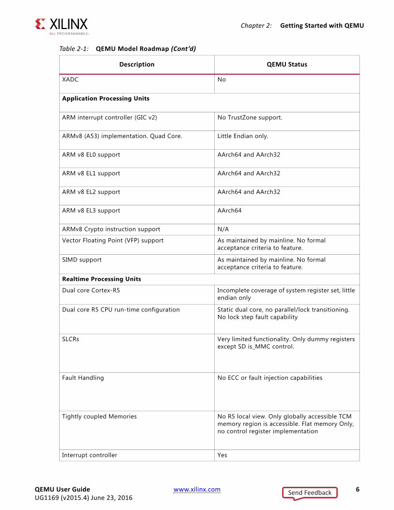
XADC No
Application Processing Units
ARM interrupt controller (GIC v2) No TrustZone support.
ARMv8 (A53) implementation. Quad Core. Little Endian only.
ARM v8 EL0 support AArch64 and AArch32
ARM v8 EL1 support AArch64 and AArch32
ARM v8 EL2 support AArch64 and AArch32
ARM v8 EL3 support AArch64
ARMv8 Crypto instruction support N/A
Vector Floating Point (VFP) support As maintained by mainline. No formal acceptance criteria to feature.
SIMD support As maintained by mainline. No formal acceptance criteria to feature.
Realtime Processing Units
Dual core Cortex-R5 Incomplete coverage of system register set, little endian only
Dual core R5 CPU run-time configuration Static dual core, no parallel/lock transitioning. No lock step fault capability
SLCRs Very limited functionality. Only dummy registers except SD is_MMC control.
Fault Handling No ECC or fault injection capabilities
Tightly coupled Memories No R5 local view. Only globally accessible TCM memory region is accessible. Flat memory Only, no control register implementation
Interrupt controller Yes
Table 2-1: QEMU Model Roadmap (Cont’d)
Description QEMU Status
QEMU User Guide www.xilinx.com 6UG1169 (v2015.4) June 23, 2016
Send Feedback
Chapter 2: Getting Started with QEMU
AMBA AXI Bus
AMBA/AXI bus interconnect system Simple bus model, no AXI/AMBA-specific features (such as MIDs; No access error functionality).
Bus quality of service monitoring and control N/A.
On Chip Memory Yes.
Additional MP SoC Capabilities
Peripheral memory protection unit Limited Functionality.
Misc System controls, mainly for IOU peripherals Extremely limited functionality - only dummy registers + SD is_MMC control.
Clock/reset controllers for low-power and high power domains
Limited feature set specific to CPU functionality
Interprocessor Interrupt controller Limited connectivity specific to PMU functionality. Modelled.
PL-based AMS block N/A
Miscellaneous QEMU non-IP related feature
Ability to boot multiple software in different CPUs Yes
Create QEMU Machine models from Linux device tree binaries (DTB)s
Limited to QEMU maintained DTBs only. IPI/HSI generated DTBs unsupported.
FPDDMA No FCI and no rate-control.
LPDDMA No FCI and no rate-control.
PMU
IPI Limited Connectivity specific to PMU functionality.
Global Registers Yes
PMU Microblaze
PMU Interrupt Controller Yes
Timers
Triple Timer Counter Yes
SWDT, WDT No
Table 2-1: QEMU Model Roadmap (Cont’d)
Description QEMU Status
QEMU User Guide www.xilinx.com 7UG1169 (v2015.4) June 23, 2016
Send Feedback
Chapter 2: Getting Started with QEMU
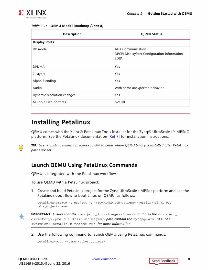
Installing Petalinux QEMU comes with the Xilinx® PetaLinux Tools Installer for the Zynq® UltraScale+™ MPSoC platform. See the PetaLinux documentation [Ref 7] for installation instructions.
TIP: Use which qemu-system-aarch64 to know where QEMU binary is installed after PetaLinux paths are set.
Launch QEMU Using PetaLinux CommandsQEMU is integrated with the PetaLinux workflow.
To use QEMU with a PetaLinux project:
1. Create and build PetaLinux project for the Zynq UltraScale+ MPSoc platform and use the PetaLinux boot flow to boot Linux on QEMU, as follows:
petalinux-create -t project -s <$DOWNLOAD_DIR>/zynqmp-<version>-final.bspcd <project-name>
IMPORTANT: Ensure that the <project_dir>/images/linux/ (and also the <project_ directory>/pre-build/linux/images/) path contain the zynqmp-arm.dtb. See <version>_petalinux_readme.txt for more information.
2. Use the following command to launch QEMU using PetaLinux commands:
petalinux-boot --qemu <other_options>
Display Ports
DP model AUX CommunicationDPCP: DisplayPort Configuration InformationEDID
DPDMA Yes
2 Layers Yes
Alpha Blending Yes
Audio With some unexpected behavior.
Dynamic resolution changes Yes
Multiple Pixel formats Not all
Table 2-1: QEMU Model Roadmap (Cont’d)
Description QEMU Status
QEMU User Guide www.xilinx.com 8UG1169 (v2015.4) June 23, 2016
Send Feedback
Chapter 2: Getting Started with QEMU
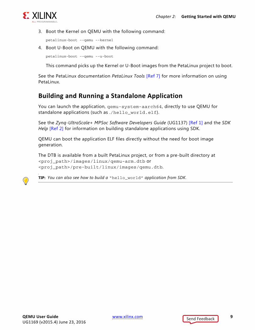
3. Boot the Kernel on QEMU with the following command:
petalinux-boot --qemu --kernel
4. Boot U-Boot on QEMU with the following command:
petalinux-boot --qemu --u-boot
This command picks up the Kernel or U-Boot images from the PetaLinux project to boot.
See the PetaLinux documentation PetaLinux Tools [Ref 7] for more information on using PetaLinux.
Building and Running a Standalone ApplicationYou can launch the application, qemu-system-aarch64, directly to use QEMU for standalone applications (such as ./hello_world.elf).
See the Zynq-UltraScale+ MPSoc Software Developers Guide (UG1137) [Ref 1] and the SDK Help [Ref 2] for information on building standalone applications using SDK.
QEMU can boot the application ELF files directly without the need for boot image generation.
The DTB is available from a built PetaLinux project, or from a pre-built directory at <proj_path>/images/linux/qemu-arm.dtb or <proj_path>/pre-built/linux/images/qemu.dtb.
TIP: You can also see how to build a “hello_world” application from SDK.
QEMU User Guide www.xilinx.com 9UG1169 (v2015.4) June 23, 2016
Send Feedback

Chapter 3
QEMU Quick Reference Card
Quick ReferenceThis is a basic template for Zynq® UltraScale+™ MPSoC device QEMU command lines:
qemu-system-aarch64 –M arm-generic-fdt –nographic -dtb <hw-dtb> \ -device loader,file=<progam.elf>,cpu=<cpu-id> \ -device loader,addr=<cpu-reset-register-addr>,data=<value>,data-len=4 \ [-boot mode=<boot-mode-id>] \ [-drive file=<image-path>, if=<( sd | mtd | pflash )>, format=raw,\ index=<index_num> ]
The following table lists the options and descriptions for QEMU commands.
Standalone Hello World ExampleThis example runs a “Hello-world” ELF file on an A53 processor. Substitute the hello_world.elf with the location your target software, as follows:
qemu-system-aarch64 -nographic -M arm-generic-fdt \ -dtb qemu-arm.dtb \ -device loader,file=./hello_world.elf,cpu=0 \ -device loader,addr=0xfd1a0104,data=0x8000000e,data-len=4
Table 3-1: QEMU Commands and Descriptions
Option Description
-device loader,file=<progam.elf>,cpu=<cpu-id>
Specify the software to run (in ELF format).
-device loader,addr=<cpu-reset-register-addr>,data=<value>,data-len=4
Release CPU from reset.
-boot mode=<boot-mode-id> Specify the boot mode pins.
-drive file=<image-path>, if=<[ sd | mtd | pflash ]>, format=raw, index=<index_num>
Specify files for persistent storage media (SD, QSPI or NAND respectively.).<index_num> specifies the respective controller for each media type.
-M arm-generic-fdt –nographic -dtb <hw-dtb>
Standard options. <hw-dtb> is the QEMU machine description.
QEMU User Guide www.xilinx.com 10UG1169 (v2015.4) June 23, 2016
Send Feedback

Chapter 3: QEMU Quick Reference Card
QEMU Command Line Reference ManualThis section provides details of QEMU command line options. The following sections detail boot, network, serial, storage, and miscellaneous command line options.
Using Extra QEMU Command Line Arguments with PetaLinux
The petalinux-boot --qemu command has an argument --qemu-args that lets you specify extra QEMU command line arguments.
Some of the optional arguments specified in the section can be passed to the PetaLinux QEMU using this switch.
IMPORTANT: Do not specify the standard, boot, or network options to petalinux-boot; those options are handled transparently by the application.
QEMU Boot Options[ -device loader,(file=<file_name>|data=<value>,data-len=4),\ [addr=<value>],[cpu=<value>],[force-raw=true] ] ...
This (repeatable) argument configures the QEMU machine for boot. The boot options perform the following tasks:
° Loads software or data into RAM sections
° Sets the CPU entry points
° Releases CPUs from reset
By default, the six ARM CPUs (four cores of Cortex-A53 and two cores of Cortex-R5) are in reset by their respective reset controllers when no software is loaded. You can use a combination of -device loader arguments to load software and setup the CPUs.
There are two basic modes for the loader argument: file mode and single transaction mode. Specify one mode only. The following subsections describe these modes.
File Mode
In file mode, the loader accepts a file as data to load. The file can be in any format and is passed using the file=<file_name> sub-option.
If the file is an ELF or a U-Boot image, the file is parsed and the sections loaded into memory as specified by the image; otherwise, the file is assumed as a raw image and loaded accordingly as an image into memory.
QEMU User Guide www.xilinx.com 11UG1169 (v2015.4) June 23, 2016
Send Feedback
Chapter 3: QEMU Quick Reference Card
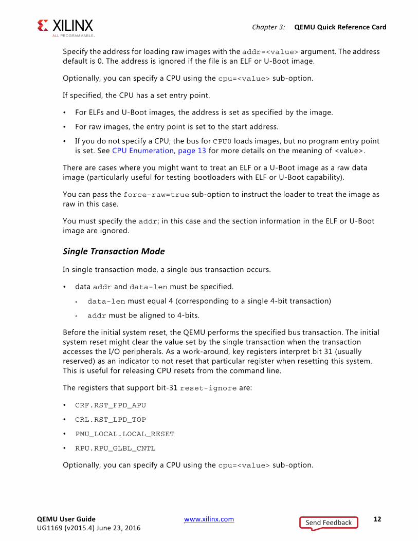
Specify the address for loading raw images with the addr=<value> argument. The address default is 0. The address is ignored if the file is an ELF or U-Boot image.
Optionally, you can specify a CPU using the cpu=<value> sub-option.
If specified, the CPU has a set entry point.
• For ELFs and U-Boot images, the address is set as specified by the image.
• For raw images, the entry point is set to the start address.
• If you do not specify a CPU, the bus for CPU0 loads images, but no program entry point is set. See CPU Enumeration, page 13 for more details on the meaning of <value>.
There are cases where you might want to treat an ELF or a U-Boot image as a raw data image (particularly useful for testing bootloaders with ELF or U-Boot capability).
You can pass the force-raw=true sub-option to instruct the loader to treat the image as raw in this case.
You must specify the addr; in this case and the section information in the ELF or U-Boot image are ignored.
Single Transaction Mode
In single transaction mode, a single bus transaction occurs.
• data addr and data-len must be specified.
° data-len must equal 4 (corresponding to a single 4-bit transaction)
° addr must be aligned to 4-bits.
Before the initial system reset, the QEMU performs the specified bus transaction. The initial system reset might clear the value set by the single transaction when the transaction accesses the I/O peripherals. As a work-around, key registers interpret bit 31 (usually reserved) as an indicator to not reset that particular register when resetting this system. This is useful for releasing CPU resets from the command line.
The registers that support bit-31 reset-ignore are:
• CRF.RST_FPD_APU
• CRL.RST_LPD_TOP
• PMU_LOCAL.LOCAL_RESET
• RPU.RPU_GLBL_CNTL
Optionally, you can specify a CPU using the cpu=<value> sub-option.
QEMU User Guide www.xilinx.com 12UG1169 (v2015.4) June 23, 2016
Send Feedback

Chapter 3: QEMU Quick Reference Card
The single transaction occurs from the perspective of the specified CPU. If you do not specify a CPU, then the system assumes CPU0.
See the Zynq UltraScale+ MPSoC Registers Users Guide (UG1087) [Ref 6] for more information about registers.
CPU Enumeration
The cpu=<value> argument interprets value are shown in the following table:
ADVANCED: If you edit the /cpus dtb node, these enumerations change. The enumerations of the CPUs matches the DTS /cpus node ordering.
Hot Loading
You can use the loader at runtime to load new software into an already running system. This is accessible from the QEMU monitor. See the Non-Graphical I/O Option, page 17 for information on accessing the monitor.
From the monitor, you can stop the emulation using the stop command:
(qemu) stop
You can then use the loader to add new software or release CPUs from reset. The syntax is:
(qemu) device_add loader,(file=<file>|data=<value>,data len=4),\ [addr=<value>],[cpu=<value>],[force-raw=true]
All sub-options are the same as described in the previous section. The emulation can then be resumed (with the new memory and CPU state from the loading operations) using the following c command:
(qemu) c
Table 3-2: CPU Enumeration Values
Value CPU
0 A53-0
1 A53-1
2 A53-2
3 A53-3
4 R5-0
5 R5-1
QEMU User Guide www.xilinx.com 13UG1169 (v2015.4) June 23, 2016
Send Feedback
Chapter 3: QEMU Quick Reference Card
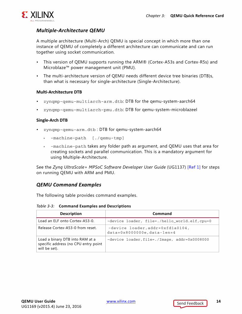
Multiple-Architecture QEMU
A multiple architecture (Multi-Arch) QEMU is special concept in which more than one instance of QEMU of completely a different architecture can communicate and can run together using socket communication.
• This version of QEMU supports running the ARM® (Cortex-A53s and Cortex-R5s) and Microblaze™ power management unit (PMU).
• The multi-architecture version of QEMU needs different device tree binaries (DTB)s, than what is necessary for single-architecture (Single-Architecture).
Multi-Architecture DTB
• zynqmp-qemu-multiarch-arm.dtb: DTB for the qemu-system-aarch64
• zynqmp-qemu-multiarch-pmu.dtb: DTB for qemu-system-microblazeel
Single-Arch DTB
• zynqmp-qemu-arm.dtb : DTB for qemu-system-aarch64
° -machine-path [./qemu-tmp]
° -machine-path takes any folder path as argument, and QEMU uses that area for creating sockets and parallel communication. This is a mandatory argument for using Multiple-Architecture.
See the Zynq UltraScale+ MPSoC Software Developer User Guide (UG1137) [Ref 1] for steps on running QEMU with ARM and PMU.
QEMU Command Examples
The following table provides command examples.
Table 3-3: Command Examples and Descriptions
Description Command
Load an ELF onto Cortex-A53-0. -device loader, file=./hello_world.elf,cpu=0
Release Cortex-A53-0 from reset. -device loader,addr=0xfd1a0104, data=0x8000000e,data-len=4
Load a binary DTB into RAM at a specific address (no CPU entry point will be set).
-device loader,file=./Image, addr=0x0008000
QEMU User Guide www.xilinx.com 14UG1169 (v2015.4) June 23, 2016
Send Feedback
Chapter 3: QEMU Quick Reference Card
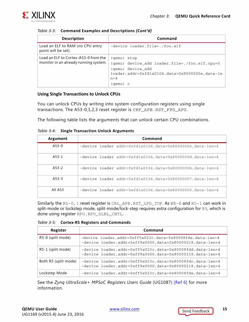
Using Single Transactions to Unlock CPUs
You can unlock CPUs by writing into system configuration registers using single transactions. The A53-0,1,2,3 reset register is CRF_APB.RST_FPD_APU.
The following table lists the arguments that can unlock certain CPU combinations.
Similarly the R5-0,1 reset register is CRL_APB.RST_LPD_TOP. As R5-0 and R5-1 can work in split-mode or lockstep mode, split-mode/lock-step requires extra configuration for R5, which is done using register RPU.RPU_GLBL_CNTL.
See the Zynq UltraScale+ MPSoC Registers Users Guide (UG1087) [Ref 6] for more information.
Load an ELF to RAM (no CPU entry point will be set).
-device loader,file=./foo.elf
Load an ELF to Cortex-A53-0 from the monitor in an already running system.
(qemu) stop
(qemu) device_add loader,file=./foo.elf,cpu=0
(qemu) device_add loader,addr=0xfd1a0104,data=0x8000000e,data-len=4
(qemu) c
Table 3-4: Single Transaction Unlock Arguments
Argument Command
A53-0 -device loader addr=0xfd1a0104,data=0x8000000e,data-len=4
A53-1 -device loader addr=0xfd1a0104,data=0x8000000d,data-len=4
A53-2 -device loader addr=0xfd1a0104,data=0x8000000b,data-len=4
A53-3 -device loader addr=0xfd1a0104,data=0x80000007,data-len=4
All A53 -device loader addr=0xfd1a0104,data=0x80000000,data-len=4
Table 3-5: Cortex-R5 Registers and Commands
Register Command
R5-0 (split mode) -device loader,addr=0xff5e023c,data=0x80008fde,data-len=4 -device loader,addr=0xff9a0000,data=0x80000218,data-len=4
R5-1 (split mode) -device loader,addr=0xff5e023c,data=0x80008fdd,data-len=4-device loader,addr=0xff9a0000,data=0x80000218,data-len=4
Both R5 (split mode) -device loader,addr=0xff5e023c,data=0x80008fdc,data-len=4-device loader,addr=0xff9a0000,data=0x80000218,data-len=4
Lockstep Mode -device loader,addr=0xff5e023c,data=0x80008fde,data-len=4
Table 3-3: Command Examples and Descriptions (Cont’d)
Description Command
QEMU User Guide www.xilinx.com 15UG1169 (v2015.4) June 23, 2016
Send Feedback
Chapter 3: QEMU Quick Reference Card
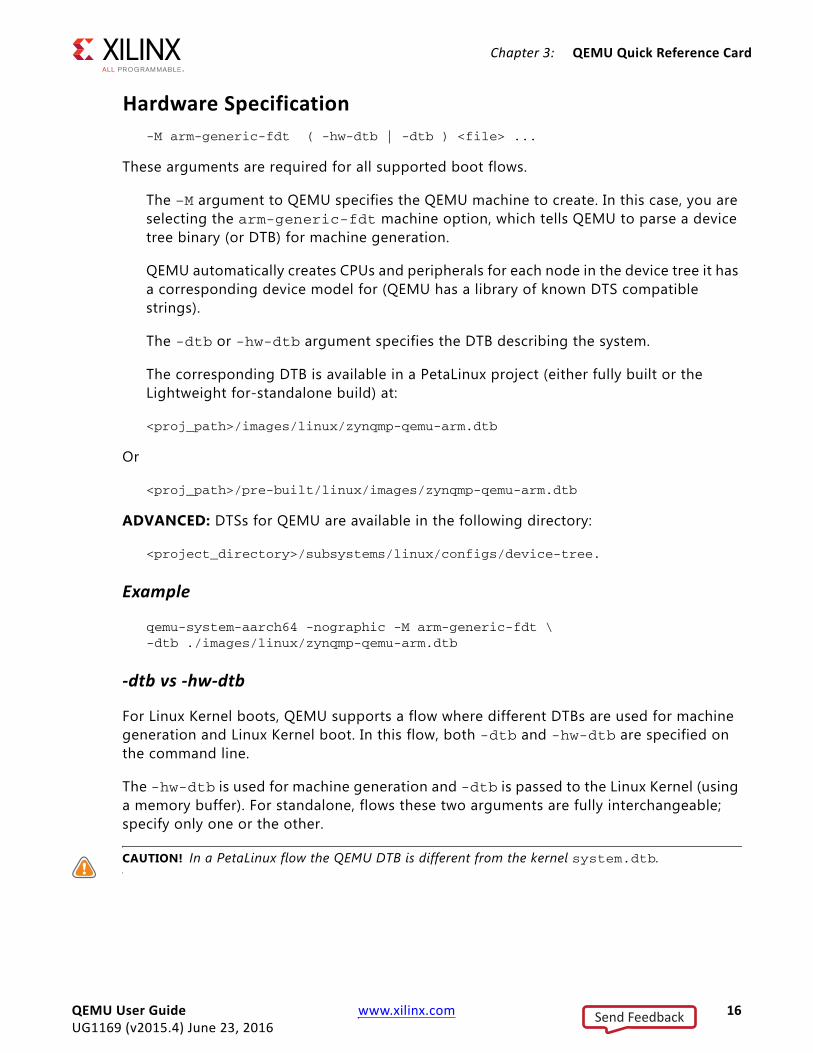
Hardware Specification-M arm-generic-fdt ( -hw-dtb | -dtb ) <file> ...
These arguments are required for all supported boot flows.
The –M argument to QEMU specifies the QEMU machine to create. In this case, you are selecting the arm-generic-fdt machine option, which tells QEMU to parse a device tree binary (or DTB) for machine generation.
QEMU automatically creates CPUs and peripherals for each node in the device tree it has a corresponding device model for (QEMU has a library of known DTS compatible strings).
The -dtb or -hw-dtb argument specifies the DTB describing the system.
The corresponding DTB is available in a PetaLinux project (either fully built or the Lightweight for-standalone build) at:
<proj_path>/images/linux/zynqmp-qemu-arm.dtb
Or
<proj_path>/pre-built/linux/images/zynqmp-qemu-arm.dtb
ADVANCED: DTSs for QEMU are available in the following directory:
<project_directory>/subsystems/linux/configs/device-tree.
Example
qemu-system-aarch64 -nographic -M arm-generic-fdt \-dtb ./images/linux/zynqmp-qemu-arm.dtb
-dtb vs -hw-dtb
For Linux Kernel boots, QEMU supports a flow where different DTBs are used for machine generation and Linux Kernel boot. In this flow, both -dtb and -hw-dtb are specified on the command line.
The -hw-dtb is used for machine generation and -dtb is passed to the Linux Kernel (using a memory buffer). For standalone, flows these two arguments are fully interchangeable; specify only one or the other.
CAUTION! In a PetaLinux flow the QEMU DTB is different from the kernel system.dtb.
QEMU User Guide www.xilinx.com 16UG1169 (v2015.4) June 23, 2016
Send Feedback
Chapter 3: QEMU Quick Reference Card
QEMU DTS are different for single and multi-architecture models.
• Single-arch : zynqmp-qemu-arm.dtb
• Multi-arch : zynqmp-qemu-multiarch-arm.dtb, zynqmp-qemu-multiarch-pmu.dtb
Non-Graphical I/O Option
-nographic
By default, QEMU attempts to create a display for user I/O. This option instructs the QEMU that there is no need for a display and I/O is serial.
QEMU attaches the invoking terminal to the serial port in this case (in the default use cases, this is UART0). See Serial Options, page 24 for more information and choices.
In this mode, the QEMU monitor (a command line interface for sending control commands to QEMU) is multiplexed on stdio. To switch between the serial port and the monitor, use the following command:
CTRL-a c
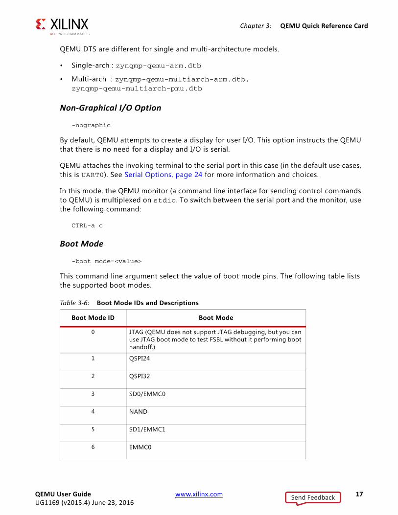
Boot Mode
-boot mode=<value>
This command line argument select the value of boot mode pins. The following table lists the supported boot modes.
Table 3-6: Boot Mode IDs and Descriptions
Boot Mode ID Boot Mode
0 JTAG (QEMU does not support JTAG debugging, but you can use JTAG boot mode to test FSBL without it performing boot handoff.)
1 QSPI24
2 QSPI32
3 SD0/EMMC0
4 NAND
5 SD1/EMMC1
6 EMMC0
QEMU User Guide www.xilinx.com 17UG1169 (v2015.4) June 23, 2016
Send Feedback

Chapter 3: QEMU Quick Reference Card
Storage MediaSeveral disk and storage media interfaces are modeled. You can pass each to a regular file(s) to use for stored data. QEMU updates the files so the data can be persistent across multiple sessions.
Argument Format
The format is:
-drive file=<image-path>, if=(mtd|sd|pflash),format=raw,index=<value>[,readonly]
The argument allows specification of extra options such as marking the file as read-only.
The argument can also be used to specify the index of the device, allowing specifying files for devices in an order-independent way. The following table lists the supported storage media.
Table 3-7: Supported Storage Media
Description Format Size
QSPI LCS Dual Parallel QSPI lower-chip-select or Single mode QSPI.
if=mtd,index=0 64MB
QSPI UCS Dual Parallel QSPI upper-chip-select or Single mode QSPI.
if=mtd,index=1 64MB
SPI0 CS0 4x SPI flashes attached to SPI controller 0
if=mtd,index=2 1MB
SPI0 CS1 if=mtd,index=3 1MB
SPI0 CS2 if=mtd,index=4 1MB
SPI0 CS3 if=mtd,index=5 1MB
SPI1 CS0 4x SPI flashes attached to SPI controller 1
if=mtd,index=6 1MB
SPI1 CS1 if=mtd,index=7 1MB
SPI1 CS2 if=mtd,index=8 1MB
SPI1 CS3 if=mtd,index=9 1MB
SD0 SD card attached to SD controller 0 if=sd,index=0 512MB
SD1 SD card attached to SD controller 1 if=sd,index=1 512MB
EMMC0 EMMC attached to SDHC0 if=sd,index=2 512MB
EMMC1 EMMC attached to SDHC1 If=sd,index=3 512MB
NAND NAND flash attached to NAND controller CS=0
if=pflash,index=0 4.7GB
NAND NAND flash attached to NAND controller CS=1
if=pflash,index=1 4.7 GB
QEMU User Guide www.xilinx.com 18UG1169 (v2015.4) June 23, 2016
Send Feedback
Chapter 3: QEMU Quick Reference Card
QSPIQSPI is modeled with 2x Micron n25q512a11 parts (64MB each) parts. The SPI flashes connect in a dual-parallel arrangement. The file size for each should match exactly 64MB.
If you are using only a single mode QSPI, then only one QSPI argument is needed.
For each, if an image is not provided QEMU still models the flash, but initializes with NULL data and discards the data after QEMU exists. Data can be written and read back within a single session in this case.
Flash Striper UtilityIn parallel mode, that the QSPI data passes in for each flash is unique to that flash chip. Because the QSPI controller implements bit-striping in dual parallel mode, a special utility is needed to take a single QSPI data image and format into the two images. The syntax is as follows:
flash_strip_bw <input> <out1> <out0>
where:
° <input> is a 128MB image.
° <out0> and <out1> are the two 64MB images passable to the –mtdblock arguments for QSPI.
IMPORTANT: flash-strip-bw is done the reverse order to QEMU.
The reverse is also possible, taking the two striped images and converting them back to a single 64MB image as shown in the following command:
flash_unstrip_bw <output> <in1> <in0>
Building the Flash Striper
Compile for your host with the following commands:
SOURCE=flash_stripe.cgcc $SOURCE -o flash_strip_bw -DFLASH_STRIP_BWgcc $SOURCE -o flash_unstrip_bw -DUNSTRIP -DFLASH_STRIP_BW
The Flash Strip utility is available as a part of the qemu_utilities.
QEMU User Guide www.xilinx.com 19UG1169 (v2015.4) June 23, 2016
Send Feedback

Chapter 3: QEMU Quick Reference Card
The following table lists the supported SPI Flash models.
SPIThe SPI controllers each have 4x SST25WF080 1MB SPI flashes connected. The image size should match exactly 1MB.
For each SPI Flash, if an image is not provided QEMU still models the flash, but initializes with NULL data and discards the data after QEMU exits. Data can be written and read back within a single session in this case.
Table 3-8: Supported QSPI Flash Models
Vendor Flash ModelsAtmel at25fs010, 25fs040, at25df041a, at25df321a, at25df641, at26f004, at26df081a,
at26df161a, at26df321, at45db081d
EON -- en25xxx en25f32, en25p32, en25q32b, en25p64, en25q64
GigaDevice gd25q32, gd25q64
Intel/Numonyx-- xxxs33b
160s33b, 320s33b, 640s33b n25q064
Macronix mx25l2005a, mx25l4005a,mx25l8005, mx25l1606e, mx25l3205d, mx25l6405d mx25l12805d, mx25l12855e, mx25l25635e, mx25l25655e
Micron n25q032a11. n25q032a13, n25q064a11, n25q064a13, n25q128a11, n25q128a13 n25q256a11, n25q256a13, n25q512a11, n25q512a1
Spansion -- single (large) sector size only, at least for the chips listed here (without boot sectors)
s25sl032p, s25sl064p, s25fl256s0, s25fl256s1, s25fl512s, s70fl01gs, s25sl12800, s25sl12801, s25fl129p0, s25fl129p1, s25sl004a, s25sl008a, s25sl016as, 25sl032a s25sl064a, s25fl016k, s25fl064k
Winbond -- w25x “blocks” are 64k, “sectors” are 4KiB
w25x10, w25x20, w25x40, w25x80, w25x16, w25x32, w25q32, w25q32dw, w25x64. w25q64, w25q80, w25q80b, w25q256
Numonyx 25q128
SST sst25vf040b, sst25vf080b, sst25vf016b, sst25vf032b, sst25wf512, sst25wf010, sst25wf020, sst25wf040, sst25wf080
ST Microelectronics m25p05, m25p10, m25p20, m25p40, m25p80, m25p16, m25p32, m25p64, m25p128, n25q032, m45pe10, m45pe80, m45pe16, m25pe20, m25pe80, m25pe16, m25px32, m25px32-s0, m25px32-s1, m25px64
QEMU User Guide www.xilinx.com 20UG1169 (v2015.4) June 23, 2016
Send Feedback
Chapter 3: QEMU Quick Reference Card
NANDQEMU emulates a single MT29F32G08ABCDBJ4 NAND flash part attached to the NAND controller.
If an image is not provided, QEMU models the flash, but initializes with NULL data and discards the data after QEMU exists. Data can be written and read back within a single session in this case.
QEMU requires that NAND storage images be in a special format (to account for out-of-band (OOB) data). A special utility is needed to take an image and format it for QEMU NAND. The input data is laid-out as the in-band data and OOB data is set to all-ones, interspersed with the in-band data as expected by QEMU.
qemu-nand-creator 16384 1216 256 1048 672 < <input>
The output file is approximately 4.7GB in this case. 16384 (16k) specifies the page size of the NAND part. This is a sparse file which occupies 1.5G on disk.
Building the Nand Creator
gcc qemu-nand-creator.c -o qemu-nand-creator
See QEMU utilities for qemu-nand-creator.c .
SDQEMU models an SD card for -drive file=<file_path>, if=sd with index 2,3.
The SD card model in QEMU is generic and does not attempt to model a specific physical part. The size of the input file initializes the size of the emulated SD card. Only 512MB SD images are officially supported, although powers of two around that order of magnitude will work.
IMPORTANT: SDXC (>32GB) sizes do not work.
If an SD argument is not specified, no SD card is modeled, the corresponding SD slot is ejected.
Note: This is different form the SPI and NAND, where if there is no argument those modes still model a physical device.
QEMU User Guide www.xilinx.com 21UG1169 (v2015.4) June 23, 2016
Send Feedback
Chapter 3: QEMU Quick Reference Card
EMMCQEMU will model an EMMC card for -drive file=<file_path>,if=sd with index 2,3. EMMC connects to respective host interface controllers, based on the slcr settings.
The size of the input file initializes the size of the emulated MMC card. Only 512MB images are supported, although powers of two, around that order of magnitude, will work.
Passing Bootable ImagesBoot images are passed to the QEMU using the command line with the storage media options. This is useful for testing, or testing with, FSBL or U-Boot bootloaders. See the Bootgen documentation in the Zynq UltraScale+ MP SoC Software Developers Guide [Ref 1] for how to create the bootable images.
See the Example, page 16 command for a comprehensive suite of examples for bootable image commands.
Chardev Options-chardev backend, id=id [,options]
The -chardev arguments lets you create a character device. This can be thought of as a file descriptor that routes text from inside QEMU to outside QEMU. The -chardev arguments consists of three main parts:
1. The output
2. If the chardev is muxable
3. The ID of this chardev
Character Device Option Examples
-chardev null,id=id[,mux=<on|off>]-chardev socket,id=id[,host=host],port=port,[to=to],[ipv4],[ipv6]\ ,[nodelay],[reconnect=seconds],[server],[nowait][,telnet]\ ,[reconnect=seconds] [mux=<on|off>] (tcp)
-chardev socket,id=id,path=path[,server][,nowait][,telnet]\ ,[reconnect=seconds],[mux=<on|off>] (unix)
-chardev udp,id=id[,host=host],port=port[,localaddr=localaddr]\ ,[localport=localport],[ipv4],[ipv6],[mux=on|off]
-chardev msmouse,id=id, [mux=on|off]
-chardev vc,id=id[[,width=width][,height=height]][[,cols=cols]\,[rows=rows]] ,mux=on|off]
QEMU User Guide www.xilinx.com 22UG1169 (v2015.4) June 23, 2016
Send Feedback

Chapter 3: QEMU Quick Reference Card
-chardev ringbuf,id=id,[size=size]
-chardev file,id=id,path=path,[mux=on|off]
-chardev pipe,id=id,path=path[,mux=on|off]
-chardev pty,id=id[,mux=on|off]
-chardev stdio,id=id[,mux=on|off][,signal=on|off]
-chardev serial,id=id,path=path[,mux=on|off]
-chardev tty,id=id,path=path[,mux=on|off]
-chardev parallel,id=id,path=path[,mux=on|off]
-chardev parport,id=id,path=path[,mux=on|off]
STDIOThe following is an example chardev:
-chardev stdio,mux=on,id=terminal
In this case anything sent to the chardev is redirected to the standard I/O. This chardev supports muxing and is called terminal.
Server (TCP Socket)The following is an example of using chardev to connect to a server:
-chardev socket,id=terminal,host=localhost,port=4444,mux=on
The server can be nc, in this case use:
nc -k -l localhost 4444
Socket (UNIX Socket)The following is an example of connecting to a standard UNIX socket:
-chardev socket,id=output,path=/tmp/socket,mux=on
The socket can be created by nc by using:
nc -k -lU /tmp/socket
QEMU User Guide www.xilinx.com 23UG1169 (v2015.4) June 23, 2016
Send Feedback
Chapter 3: QEMU Quick Reference Card
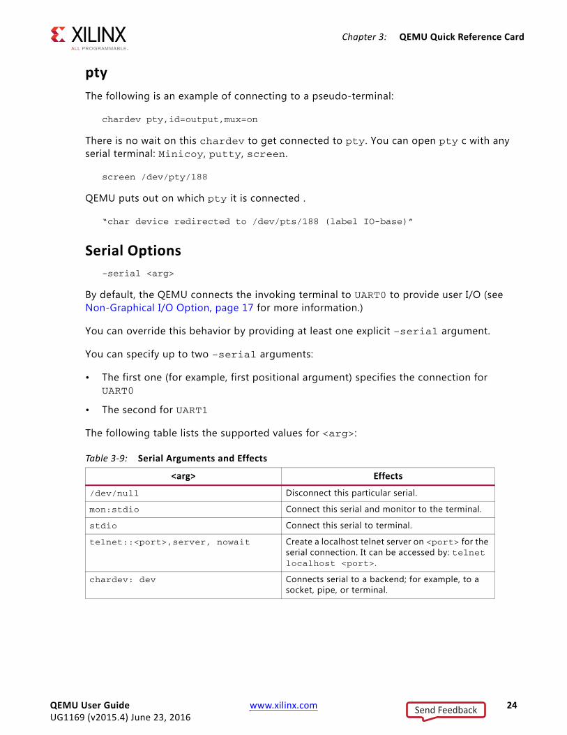
ptyThe following is an example of connecting to a pseudo-terminal:
chardev pty,id=output,mux=on
There is no wait on this chardev to get connected to pty. You can open pty c with any serial terminal: Minicoy, putty, screen.
screen /dev/pty/188
QEMU puts out on which pty it is connected .
“char device redirected to /dev/pts/188 (label IO-base)”
Serial Options-serial <arg>
By default, the QEMU connects the invoking terminal to UART0 to provide user I/O (see Non-Graphical I/O Option, page 17 for more information.)
You can override this behavior by providing at least one explicit –serial argument.
You can specify up to two –serial arguments:
• The first one (for example, first positional argument) specifies the connection for UART0
• The second for UART1
The following table lists the supported values for <arg>:
Table 3-9: Serial Arguments and Effects
<arg> Effects
/dev/null Disconnect this particular serial.
mon:stdio Connect this serial and monitor to the terminal.
stdio Connect this serial to terminal.
telnet::<port>,server, nowait Create a localhost telnet server on <port> for the serial connection. It can be accessed by: telnet localhost <port>.
chardev: dev Connects serial to a backend; for example, to a socket, pipe, or terminal.
QEMU User Guide www.xilinx.com 24UG1169 (v2015.4) June 23, 2016
Send Feedback

Chapter 3: QEMU Quick Reference Card
Serial Command Examples
The following are some of the common non-default serial setups.
• Disconnect all serials: -serial /dev/null -serial /dev/null
• Connect UART1 to the terminal and ignore UART0: -serial /dev/null -serial mon:stdio
• Connect UART0 to terminal and UART1 to telnet: -serial mon:stdio -serial telnet::1234,server,nowait
• Connect UART0 to chardev socket:-serial chardev:terminal
Note: terminal is the chardev device ID. See details the Chardev Options, page 22.
Monitor Options• -monitor: specifies where to send the QEMU monitor. Generally, this is sent to the
standard I/O which can be done with the following command:
-monitor chardev:terminal
Networking Options-net nic -net user -tftp <directory>
This connects GEM0 to a virtual network, with a TFTP server hosting the argument directory. The TFTP server IP is 10.0.2.2. The guest software can configure the machine to an IP on the same subnet (for example 10.0.2.4) and communicate.
The following command connects all four GEMs in the zynqmp to a virtual network:
-nt nic -net nic -net nic -net user
See the QEMU public documentation for more comprehensive listing of QEMU networking options.
Debug Options• QEMU Arguments: Enabling and using the GDB stub:
-gdb tcp::<host_name>:<port> -S
Where:
° –gdb: Creates a GDB stub on the local host at the specified port.
° –S: Causes the emulation to start in the pause state. This allows you to attach a debugger before software starts executing. You can attach your GDB to QEMU as follows: (gdb) target remote :<port>
QEMU User Guide www.xilinx.com 25UG1169 (v2015.4) June 23, 2016
Send Feedback
Chapter 3: QEMU Quick Reference Card
On the GDB host, use the GDB that corresponds to your build toolchain; for example:
° aarch64-none-elf-gdb or aarch64-linux-gnu-gdb for debugging A53 code.
or
° arm-none-eabi-gdb for R5 software.
QEMU emulation can be resumed using a continue in GDB, as shown in the following command:
(gdb) c
Breakpoints can be inserted as normal. Either symbolic function names, file lines, or text memory addresses can be used. See the ARM Information Center [Ref 12] for more information.
Debug-Related Monitor CommandsYou can use a range of QEMU monitor commands to access helpful debug information and perform some basic operations. The following are a few of the more commonly used options. See Non-Graphical I/O Option, page 17 for information on accessing the monitor.
• Stopping and resuming the VM:
(qemu) stop
(qemu) c
These commands stop and resume the emulation, respectively.
If QEMU is started with the –S argument, you can use the c command to commence emulation.
Display OptionsThe QEMU display option emulates a virtual monitor for the display applications.
IMPORTANT: To make use of the Display option, do not pass the -nographic argument in the command line; it restricts the ability to create a display console.
CAUTION! PetaLinux QEMU does Not include SDL support for Display Monitor Emulation, It is recommended that you build QEMU from source with SDL enabled. See Building QEMU from Source, page 31.
QEMU User Guide www.xilinx.com 26UG1169 (v2015.4) June 23, 2016
Send Feedback

Chapter 3: QEMU Quick Reference Card
The following command option, when passed on the QEMU command line, creates a VNC session through which you can view the display console:
-vnc <hostname>:<display>
For example, the command -vnc localhost:1 connects to a VNC session using VNC viewer on localhost:1, where 1 represents the display ID. In this way you can have n number of display monitors open.
Listening on a VNC SessionYou can connect to a display at any time using the -vnc <hostname>:<display> command; however, if you need the QEMU to wait until it is connected to a VNC session, configure the QEMU to work with a listening VNC session.
-vnc <hostname>:<tcp port number>,reverse
For example, -vnc localhost:5501,reverse, will be able to connect to a listening VNC session with display-id 1.
Note: The TCP port number for display ID 1 maps as 5500+d, where d is the display ID.
Running the VNC viewer with -listen 1 results in the host listening for connections on the VNC session with display 1.
Listing and Selecting CPUs in the SystemFrom the QEMU Monitor Console, use the following commands:
(qemu) info cpus(qemu) cpu <value>
Where:
° The info cpus lists out the CPUs in the system and indicated the currently selected CPU. In a normal setup there are six CPUs: 4 x A53 and 2 x R5. QEMU has the concept of a currently selected CPU with respect to some monitor commands. This is very similar to GDBs concept of a currently selected thread.
° Change the selected CPU using the cpu <value> command. The <value> is a number from 0 to 5 that corresponds to the QEMU CPU indexes.
° CPUs with an asterisk (*) are currently selected.
See CPU Enumeration, page 13 for information on how QEMU CPU indexes match the Zynq UltraScale+ MPSoC platform CPUs.
QEMU User Guide www.xilinx.com 27UG1169 (v2015.4) June 23, 2016
Send Feedback
Chapter 3: QEMU Quick Reference Card
Inspecting CPU State(qemu) info registers
The info registers command dumps out useful information about the current CPU (such as registers and current EL) For R5 CPUs. R15 is the program counter.
See the ARM Architecture reference manuals for the meaning of specific pieces of information.
Inspecting Physical Memory(qemu) ( xp | x ) <addr>(qemu) memsave <addr> <length> <file>
Use these commands to dump memory data. The x or xp command can be used to read a single address:
° xp: (qemu) xp 0x1234F00D
- x uses virtual addresses for the currently selected cpu
- xp uses physical addresses
° The memsave command saves a buffer of specified length (<length>) and address (<addr>) to a file specified by <file>, where <file> is the data buffer as raw binary data.
For example: (qemu) memsave 0xc0ae1a80 16384 dumpmem.logbuf
Linux Kernel Logbuf ExtractionThe following instructions are directly applicable to booting Linux Zynq® UltraScale+™ MPSoC QEMU. There is more information available at Linux Kernel Logbuf Extraction [Ref 16].
Examples for Single Arch
This section provides some example complete fully elaborated QEMU command lines. Substitute particular arguments to suite your application as needed. See the Command Line Argument Manual for further details of each options. For each command, it is assumed the current working directory is a PetaLinux project root.
You can run the commands without a PetaLinux project but file paths of boot components will need to be adjusted.
See Storage Media, page 18 as required for details on how to generate storage media files for QSPI, NAND, and SD.
QEMU User Guide www.xilinx.com 28UG1169 (v2015.4) June 23, 2016
Send Feedback

Chapter 3: QEMU Quick Reference Card
FSBL as an Application on A53-0
In each of the following examples, FSBL is run as the application; however, these command line formats are applicable to other standalone software. Substituting the FSBL ELF file for another standalone application is valid.
A53-0 FSBL in JTAG Mode
qemu-system-aarch64 -M arm-generic-fdt -nographic \-dtb ./images/linux/zynqmp-qemu-arm.dtb \-device loader,file=./images/linux/zynqmp_a53_fsbl.elf,cpu=0 \-device loader,addr=0xfd1a0104,data=0x8000000e,data-len=4
A53-0 FSBL in QSPI Boot Mode (Single)
qemu-system-aarch64 -M arm-generic-fdt -nographic \-dtb ./images/linux/zynqmp-qemu-arm.dtb \-device loader,file=./images/linux/zynqmp_a53_fsbl.elf,cpu=0 \-device loader,addr=0xfd1a0104,data=0x8000000e,data-len=4 \-drive file=qemu_qspi.bin,if=mtd,format=raw,index=0\-boot mode=1
A53-0 FSBL in QSPI Boot Mode (Dual Parallel)
qemu-system-aarch64 -M arm-generic-fdt -nographic \-dtb ./images/linux/zynqmp-qemu-arm.dtb \-device loader,file=./images/linux/zynqmp_a53_fsbl.elf,cpu=0 \-device loader,addr=0xfd1a0104,data=0x8000000e,data-len=4 \-drive file=qemu_qspi_high.bin,if=mtd,format=raw,index=0\-drive file=qemu_qspi_low.bin,if=mtd,format=raw,index=1\-boot mode=1
A53-0 FSBL in SD Boot Mode
qemu-system-aarch64 -M arm-generic-fdt -nographic \-dtb ./images/linux/zynqmp-qemu-arm.dtb \-device loader,file=./images/linux/zynqmp_a53_fsbl.elf,cpu=0 \-device loader,addr=0xfd1a0104,data=0x8000000e,data-len=4 \-drive file=qemu_sd.img,if=sd,format=raw,index=0\-boot mode=3
A53-0 FSBL in NAND Boot Mode
qemu-system-aarch64 -M arm-generic-fdt -nographic \-dtb ./images/linux/zynqmp-qemu-arm.dtb \-device loader,file=./images/linux/zynqmp_a53_fsbl.elf,cpu=0 \-device loader,addr=0xfd1a0104,data=0x8000000e,data-len=4 \-drive file=qemu_nand.bin,if=pflash,format=raw,index=0-boot mode=4
QEMU User Guide www.xilinx.com 29UG1169 (v2015.4) June 23, 2016
Send Feedback
Chapter 3: QEMU Quick Reference Card
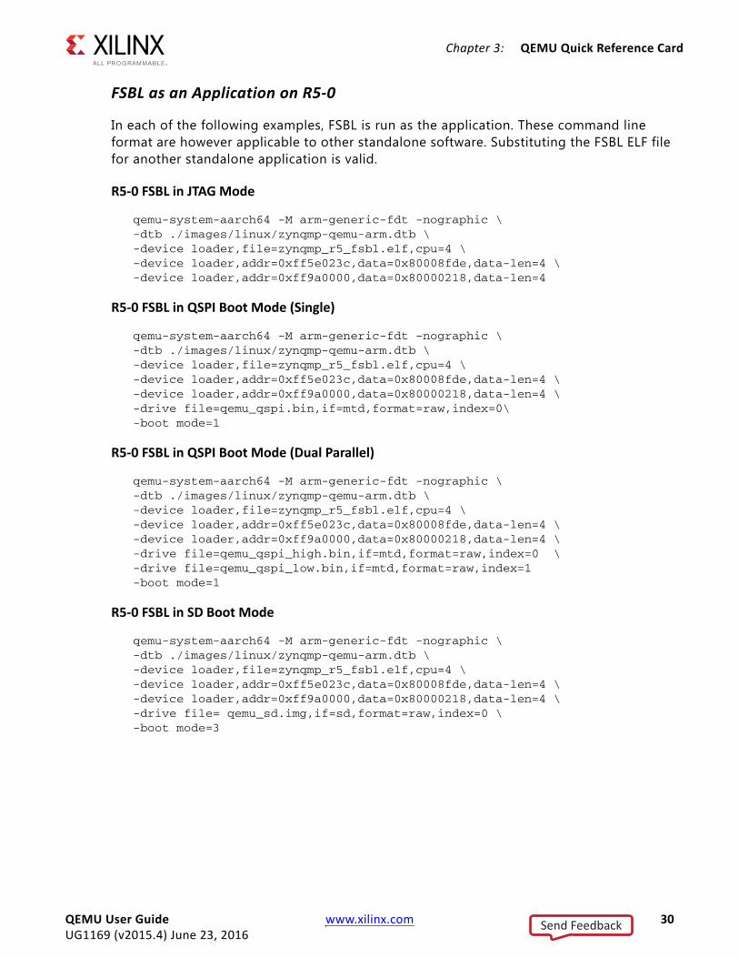
FSBL as an Application on R5-0
In each of the following examples, FSBL is run as the application. These command line format are however applicable to other standalone software. Substituting the FSBL ELF file for another standalone application is valid.
R5-0 FSBL in JTAG Mode
qemu-system-aarch64 -M arm-generic-fdt -nographic \-dtb ./images/linux/zynqmp-qemu-arm.dtb \-device loader,file=zynqmp_r5_fsbl.elf,cpu=4 \-device loader,addr=0xff5e023c,data=0x80008fde,data-len=4 \-device loader,addr=0xff9a0000,data=0x80000218,data-len=4
R5-0 FSBL in QSPI Boot Mode (Single)
qemu-system-aarch64 -M arm-generic-fdt –nographic \-dtb ./images/linux/zynqmp-qemu-arm.dtb \-device loader,file=zynqmp_r5_fsbl.elf,cpu=4 \-device loader,addr=0xff5e023c,data=0x80008fde,data-len=4 \-device loader,addr=0xff9a0000,data=0x80000218,data-len=4 \-drive file=qemu_qspi.bin,if=mtd,format=raw,index=0\ -boot mode=1
R5-0 FSBL in QSPI Boot Mode (Dual Parallel)
qemu-system-aarch64 -M arm-generic-fdt -nographic \-dtb ./images/linux/zynqmp-qemu-arm.dtb \-device loader,file=zynqmp_r5_fsbl.elf,cpu=4 \-device loader,addr=0xff5e023c,data=0x80008fde,data-len=4 \-device loader,addr=0xff9a0000,data=0x80000218,data-len=4 \-drive file=qemu_qspi_high.bin,if=mtd,format=raw,index=0 \-drive file=qemu_qspi_low.bin,if=mtd,format=raw,index=1-boot mode=1
R5-0 FSBL in SD Boot Mode
qemu-system-aarch64 -M arm-generic-fdt -nographic \-dtb ./images/linux/zynqmp-qemu-arm.dtb \-device loader,file=zynqmp_r5_fsbl.elf,cpu=4 \-device loader,addr=0xff5e023c,data=0x80008fde,data-len=4 \-device loader,addr=0xff9a0000,data=0x80000218,data-len=4 \-drive file= qemu_sd.img,if=sd,format=raw,index=0 \-boot mode=3
QEMU User Guide www.xilinx.com 30UG1169 (v2015.4) June 23, 2016
Send Feedback
Chapter 3: QEMU Quick Reference Card
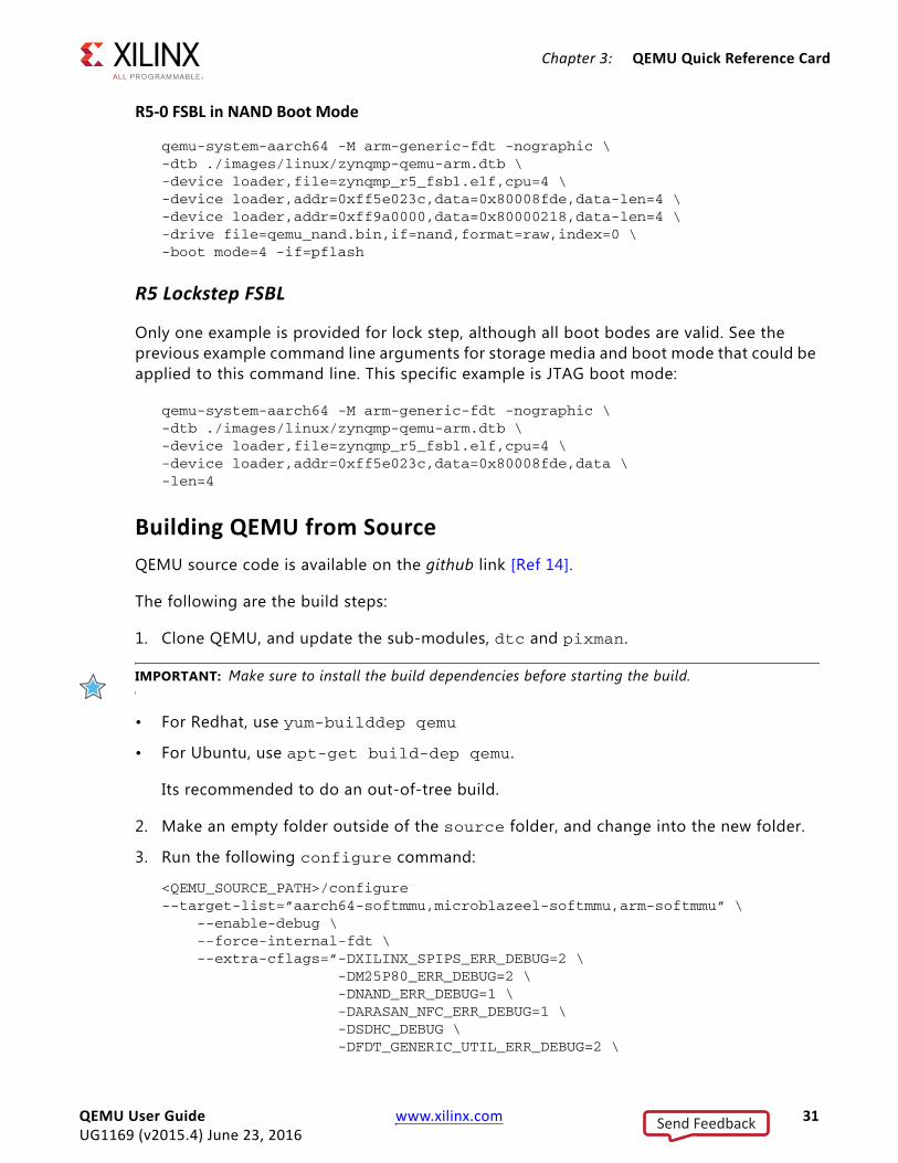
R5-0 FSBL in NAND Boot Mode
qemu-system-aarch64 -M arm-generic-fdt -nographic \-dtb ./images/linux/zynqmp-qemu-arm.dtb \-device loader,file=zynqmp_r5_fsbl.elf,cpu=4 \-device loader,addr=0xff5e023c,data=0x80008fde,data-len=4 \-device loader,addr=0xff9a0000,data=0x80000218,data-len=4 \-drive file=qemu_nand.bin,if=nand,format=raw,index=0 \-boot mode=4 -if=pflash
R5 Lockstep FSBL
Only one example is provided for lock step, although all boot bodes are valid. See the previous example command line arguments for storage media and boot mode that could be applied to this command line. This specific example is JTAG boot mode:
qemu-system-aarch64 -M arm-generic-fdt -nographic \-dtb ./images/linux/zynqmp-qemu-arm.dtb \-device loader,file=zynqmp_r5_fsbl.elf,cpu=4 \-device loader,addr=0xff5e023c,data=0x80008fde,data \-len=4
Building QEMU from SourceQEMU source code is available on the github link [Ref 14].
The following are the build steps:
1. Clone QEMU, and update the sub-modules, dtc and pixman.
IMPORTANT: Make sure to install the build dependencies before starting the build.
• For Redhat, use yum-builddep qemu
• For Ubuntu, use apt-get build-dep qemu.
Its recommended to do an out-of-tree build.
2. Make an empty folder outside of the source folder, and change into the new folder.
3. Run the following configure command:
<QEMU_SOURCE_PATH>/configure --target-list=”aarch64-softmmu,microblazeel-softmmu,arm-softmmu” \ --enable-debug \ --force-internal-fdt \ --extra-cflags=”-DXILINX_SPIPS_ERR_DEBUG=2 \ -DM25P80_ERR_DEBUG=2 \ -DNAND_ERR_DEBUG=1 \ -DARASAN_NFC_ERR_DEBUG=1 \ -DSDHC_DEBUG \ -DFDT_GENERIC_UTIL_ERR_DEBUG=2 \
QEMU User Guide www.xilinx.com 31UG1169 (v2015.4) June 23, 2016
Send Feedback
Chapter 3: QEMU Quick Reference Card
-DCADENCE_GEM_ERR_DEBUG \ -DCONFIG_FDT “ \
--disable-werror \ --enable-fdt \ --enable-sdl
4. Then run make –j16.
QEMU binaries are available at:
• <build_path>/aarch64-softmmu/qemu-system-aarch64
• <build_path>/microblazeel-softmmu/qemu-system-microblazeel
You might need to install additional libraries based on your configuration inputs.
QEMU User Guide www.xilinx.com 32UG1169 (v2015.4) June 23, 2016
Send Feedback
Chapter 4
Using XSDB with QEMU
IntroductionThe Xilinx® system debugger (XSDB) lets you download and debug application on the QEMU platform.
Using the XSDB, you can do the following:
° Download and run a bare-metal application ELF
° Suspend and resume a processor
° Debug using breakpoints
° Read and write registers
Connecting QEMUXSDB connects to QEMU GDB by using remote ports.
While passing arguments to load and run QEMU running, attach a GDB client by appending the option: -gdb tcp::<port-num> to QEMU command line.
The following is the total command:
qemu-system-aarch64 -M arm-generic-fdt -nographic \-dtb ./images/linux/zynqmp-qemu-arm.dtb –gdb tcp::1440
Note: Port number is not specific; it can be any free port.
With QEMU running, connect the QEMU using the XSDB gdbremote command shown in the following command line:
gdbremote connect <hostname>:<port-num>
Note: The hostname can be localhost or the name of the server or an IP address upon which QEMU is running.
QEMU User Guide www.xilinx.com 33UG1169 (v2015.4) June 23, 2016
Send Feedback
Chapter 4: Using XSDB with QEMU
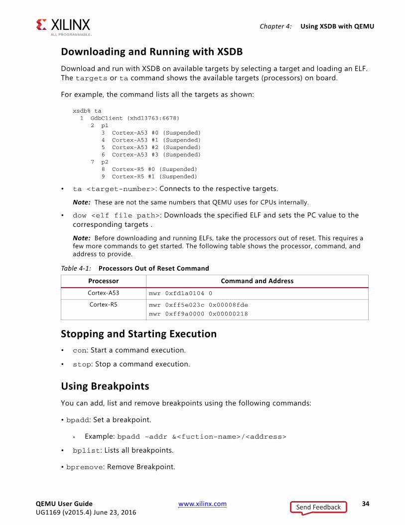
Downloading and Running with XSDBDownload and run with XSDB on available targets by selecting a target and loading an ELF. The targets or ta command shows the available targets (processors) on board.
For example, the command lists all the targets as shown:
xsdb% ta 1 GdbClient (xhdl3763:6678) 2 p1 3 Cortex-A53 #0 (Suspended) 4 Cortex-A53 #1 (Suspended) 5 Cortex-A53 #2 (Suspended) 6 Cortex-A53 #3 (Suspended) 7 p2 8 Cortex-R5 #0 (Suspended) 9 Cortex-R5 #1 (Suspended)
• ta <target-number>: Connects to the respective targets.
Note: These are not the same numbers that QEMU uses for CPUs internally.
• dow <elf file path>: Downloads the specified ELF and sets the PC value to the corresponding targets .
Note: Before downloading and running ELFs, take the processors out of reset. This requires a few more commands to get started. The following table shows the processor, command, and address to provide.
Stopping and Starting Execution• con: Start a command execution.
• stop: Stop a command execution.
Using BreakpointsYou can add, list and remove breakpoints using the following commands:
• bpadd: Set a breakpoint.
° Example: bpadd –addr &<fuction-name>/<address>
• bplist: Lists all breakpoints.
• bpremove: Remove Breakpoint.
Table 4-1: Processors Out of Reset Command
Processor Command and Address
Cortex-A53 mwr 0xfd1a0104 0
Cortex-R5 mwr 0xff5e023c 0x00008fde
mwr 0xff9a0000 0x00000218
QEMU User Guide www.xilinx.com 34UG1169 (v2015.4) June 23, 2016
Send Feedback
Chapter 4: Using XSDB with QEMU
° Example: bpremove <breakpoint number>
For more information on using breakpoints see the “XSDB” topic in the Xilinx Software Developers Kit help [Ref 2].
Reading and Writing to Memory RegistersYou can read and write to the memory of the peripherals and the DDR and OCM memory in the debugger using the mrd and mwr commands.
Note: Stop the processors when performing memory operations.
Commands
• mrd <addr>: Read memory
• mwr <addr> <value>: Write to memory
Limitations• Reset of processors command is not supported. Instead, QEMU can be restarted or use
system_reset in the QEMU monitor.
• PL bitstream loading is not supported as shown in XSDB help .
• Changing memory maps is not supported.
• JTAG is not supported.
QEMU User Guide www.xilinx.com 35UG1169 (v2015.4) June 23, 2016
Send Feedback
Chapter 5
Creating Boot Images on QEMU
IntroductionThis section details some end-to-end image generation and QEMU boot flows.
The standard FSBL, ATF, U-Boot, and Linux boot flow is the example in each case.
This specific use case is similar to PetaLinux, and you can access it more simply using the PetaLinux tool suite. This section details the lower-level tools available for complex boot flows should they be required for greater customization.
This section does not cover building the boot products. See the Zynq® UltraScale+™ MPSOC Software Developers Guide (UG1137) [Ref 1] for information on how to build the following:
° FSBL
° U-Boot
° ARM trusted firmware (ATF)
° Linux image (Kernel plus RAM disk)
° Device tree binary (DTB)
Note: (This is different from the hardware DTB that is passed to QEMU command lines.)
It is assumed all of these boot products are available. You can build all of the listed images in a standard PetaLinux project.
In the example, FSBL, ATF (bl31.elf), U-Boot runs on an A53 as shown in the BIF file. U-boot loads the Kernel onto A53.
The following run commands point to the <proj_dir>/images/linux/ folder for all the boot products. You can also use a pre-built area.
QEMU User Guide www.xilinx.com 36UG1169 (v2015.4) June 23, 2016
Send Feedback

Chapter 5: Creating Boot Images on QEMU
Using an SD for Boot (SD Boot Tutorial)
Creating a Binary File from Bootgen1. Create a binary file (.bin) for the FSBL, ATF, and U-Boot using Bootgen.
Bootgen accepts a BIF file, which contains the information about image paths and on which cores to run.
The following is the BIF file (myimg.bif):
the_ROM_image:{ [fsbl_config] a53_x64 [bootloader] ron_a53_fsbl.elf [destination_cpu=a53-0]bl31.elf [destination_cpu=a53-0]u-boot.elf}
2. Use the following command to generate the BIN file is:
bootgen -image myimg.bif -r -w -o i BOOT.BIN
TIP: Use bootgen –bif_help for more info of BIF parameters.
3. Create the SD image:
dd if=/dev/zero of=qemu_sd.img bs=128M count=1 mkfs.vfat -F 32 qemu_sd.imgmcopy -i qemu_sd.img BOOT.BIN ::/mcopy -i qemu_sd.img Image ::/mcopy -i qemu_sd.img system.dtb ::/
4. Boot the image on QEMU:
qemu-system-aarch64 -M arm-generic-fdt -nographic \-device loader,file=<proj_dir>/images/linux/ron_a53_fsbl.elf,cpu=0 \-dtb <proj_dir>/images/linux/zynqmp-qemu-arm.dtb \-device loader,addr=0xfd1a0104,data=0x8000000e,data-len=4 \-drive file=qemu_sd.img,if=sd,format=raw,index=0\-boot mode=3
Note: Even though the FSBL is packed in the SD image, it should be passed over the command line as a runnable ELF because QEMU does not contain the boot ROM.
QEMU User Guide www.xilinx.com 37UG1169 (v2015.4) June 23, 2016
Send Feedback
Chapter 5: Creating Boot Images on QEMU
Using QSPI for Boot
Creating the Binary File from Bootgen1. Create a binary file (.bin) to boot FSBL ATF, and U-Boot using Bootgen.
Bootgen accepts a BIF file, which contains the information about image paths and on which cores to run.
The following is the BIF file (myimg.bif):
the_ROM_image:{ [fsbl_config] a53_x64 [bootloader] zynqmp_a53_fsbl.elf [destination_cpu=a53-0]bl31.elf [destination_cpu=a53-0]u-boot.elf [destination_cpu=a53-0,offset=0x140000]Image [destination_cpu=a53-0,offset=0x100000]system.dtb}
2. Issue the following command to generate the BIN file:
bootgen -image myimg.bif -r -w -o i BOOT.BIN
3. Create the QSPI boot image(s) for either or both single flash mode and dual parallel mode.
Single Flash Mode
dd if=/dev/zero of=qemu_qspi.bin bs=64M count=1dd if=BOOT.BIN of=qemu_qspi.bin bs=1 seek=0 conv=notrunc
Dual Parallel Mode
dd if=/dev/zero bs=128M count=1 of=qemu_qspi_tmp.bindd if=BOOT.BIN of=qemu_qspi_tmp.bin bs=1 seek=0 conv=notruncflash_strip_bw qemu_qspi_tmp.bin qemu_qspi_low.bin qemu_qspi_high.bin
4. Boot either the single or dual image(s) on QEMU.
Single Flash Mode
qemu-system-aarch64 -M arm-generic-fdt -nographic \-dtb <proj_dir>/images/linux/zynqmp-qemu-arm.dtb \-device loader,file=<proj_dir>/ images/linux/zynqmp_a53_fsbl.elf,cpu=0 \-device loader,addr=0xfd1a0104,data=0x8000000e,data-len=4 \-drive file=qemu_qspi.bin,if=mtd,format=raw,index=0 \-boot mode=1
QEMU User Guide www.xilinx.com 38UG1169 (v2015.4) June 23, 2016
Send Feedback

Chapter 5: Creating Boot Images on QEMU
Dual Parallel Mode
qemu-system-aarch64 -M arm-generic-fdt -nographic \-dtb <proj_dir>/images/linux/zynqmp-qemu-arm.dtb \-device loader,file=<proj_dir>/images/linux/zynqmp_a53_fsbl.elf,cpu=0 \-device loader,addr=0xfd1a0104,data=0x8000000e,data-len=4 \-drive file=qemu_qspi_high.bin,if=mtd,format=raw,index=0\-drive file=qemu_qspi_low.bin,if=mtd,format=raw,index=1 -boot mode=1
TIP: See the Storage Media for more information on flash_strip_bw.
Using NAND for Boot
Creating a Binary File from Bootgen1. Create a binary file (.bin) to boot FSBL, ATF, and U-Boot using Bootgen.
Bootgen accepts a BIF file, which should contain the info about image paths and which cores on which they should run. The following is the BIF file (myimg.bif):
the_ROM_image:{ [fsbl_config] a53_x64 [bootloader] ron_a53_fsbl.elf [destination_cpu=a53-0]bl31.elf [destination_cpu=a53-0]u-boot.elf [destination_cpu=a53-0,offset=0x140000]Image [destination_cpu=a53-0,offset=0x100000]system.dtb}
2. Use the following command to generate the BIN file:
bootgen -image myimg.bif -r -w -o i BOOT.BIN
3. Create the NAND boot image(s):
qemu-nand-creator 16384 1216 256 1048 672 < BOOT.BIN
CAUTION! These steps create a 4GB image file. This is required as QEMU emulated 4GB NAND Flash.
TIP: See the Storage Media for more information on qemu-nand-creator.
QEMU User Guide www.xilinx.com 39UG1169 (v2015.4) June 23, 2016
Send Feedback
Chapter 5: Creating Boot Images on QEMU
4. Use the following command to run the NAND image on QEMU:
qemu-system-aarch64 -M arm-generic-fdt -nographic \-dtb images/linux/zynqmp-qemu-arm.dtb \-device loader,file=<proj_dir>/images/linux/zynqmp_a53_fsbl.elf,cpu=0 \-device loader,addr=0xfd1a0104,data=0x8000000e,data-len=4\-drive file=qemu_nand.bin,if=pflash,format=raw,index=0\-boot mode=4
Using TFTP for Boot In the normal JTAG boot mode, petalinux-build command has the required images in the images/linux/ directory (or) a prebuilt path (for example: pre-built/linux/images/).
1. Point QEMU to the ./images/linux directory for tftp boot.
2. Use the following command for TFTP boot.
qemu-system-aarch64 -M arm-generic-fdt -nographic \-dtb <proj_dir>/images/linux/zynqmp-qemu-arm.dtb \-device loader,file=<proj_dir>images/linux/bl31.elf,cpu=0 \-device loader,addr=0xfd1a0104,data=0x8000000e,data-len=4 \-device loader,file=<proj_dir>/images/linux/u-boot..elf \-tftp images/linux/
IMPORTANT: The /TFTP folder should contain the Image and the system.dtb.
TIP: Image Creation Steps for SD and EMMC are the same.
SD-Card Partitioning and Loading an Ubuntu-core File SystemThe following are the steps to create an SD card image.
1. Create a dummy container using qemu-img. The qemu-img is a utility used to create disk images for using with QEMU. It comes with Ubuntu packages and is also packaged with PetaLnux tools.
qemu-img create <Image name> <size>
For example: The command, qemu-img create sd.img 2G, creates a 2G raw disk, with no partitions present.
2. Create the network back end with qemu-nbd and nbd-client.
QEMU User Guide www.xilinx.com 40UG1169 (v2015.4) June 23, 2016
Send Feedback
Chapter 5: Creating Boot Images on QEMU
The qemu-nbd command creates a disk network block server making it an network block device, so that it can be connected with nbd-client.
For example:
° qemu-nbd -p 4444 sd.img & makes a network block device server, instructing the client to use port 4444 to connect.
° nbd-client localhost 4444 /dev/nbd0 connects to the created network block server. It can be accessed using the /dev/nbd0 node.
3. Create partitions using fdisk, a text-based tool used to create partitions on a disk.
Also, you could use gparted, a GUI-based partitioning tool.
fdisk /dev/nbd0 connects to the block device.
4. Create partitions, mostly two primary partitions are required.
° One is bootable partition for keeping BOOT.BIN, Image, and the system.dtb.
° Another is the partition for rootfs.
A bootable flag can be toggled using fdisk. Ensure that there is least 100Mb in the bootable partition to have enough space.
5. Write the partition table and exit.
6. Format the partitions. Always format the bootable partition using FAT file systems. The second partition can be ext2/ext4.
For example:
mkfs.vfat -F 32 /dev/nbd0p1l formats the first partitions using FAT.
mkfs.ext4 /dev/nb0p2 formats the second partition using ext4.
7. Mount the partitions and copy the necessary files. Load the Image file without initramfs, by de-selecting the []Initial RAM filesystem and RAM disk (initramfs/initrd) support option located in General Setup in menuconfig.
Note: This step in not required if performing switch-root.
8. Extract the ubutu-core available for arm64 in to the second partition.
TIP: The ubuntu-core is located on the Ubuntu-Core release page.
9. Un-mount the partition and disconnect the nbd connection using the following command: nbd-client-d /dev/nbd0.
10. Ensure that the bootargs points to appropriate device for root, which is the following: root=/dev/mmcblk0p2 rw rootfstype=ext4.
QEMU User Guide www.xilinx.com 41UG1169 (v2015.4) June 23, 2016
Send Feedback
Appendix A
Additional Resources and Legal Notices
Xilinx ResourcesFor support resources such as Answers, Documentation, Downloads, and Forums, seeXilinx Support.
Solution CentersSee the Xilinx Solution Centers for support on devices, software tools, and intellectual property at all stages of the design cycle. Topics include design assistance, advisories, and Vivado Design Suite Documentation
References
Zynq Documentation1. Zynq UltraScale+ MPSoc Software Developers Guide (UG1137)
2. Xilinx Software Developer Kit Help (UG782) (Includes XSDB)
3. OS and Libraries Document Collection (UG643)
4. Xilinx Third-Party Licensing Guide (UG763)
5. UltraScale Architecture and Product Overview (DS890)
6. Zynq UltraScale+ Registers User Guide (UG1087)
7. PetaLinux Tools
Vivado Design Suite Documentation
UltraScale Architecture Video Tutorials
QEMU User Guide www.xilinx.com 42UG1169 (v2015.4) June 23, 2016
Send Feedback

Appendix A: Additional Resources and Legal Notices
Wiki Sites8. QEMU WiKi
9. Zynq MPSoc Xen WiKi
10. GNU FTP
11. Zynq MPSoC Boot
12. ARM Information Center
13. Using GIT
14. GIT Hub
15. OpenAMP WiKi
16. QEMU Linux Kernel Logbuf Extraction
Please Read: Important Legal NoticesNOTICE: This pre-release document contains confidential and proprietary information of Xilinx, Inc. and is being disclosed to you as a participant in an early access program, under obligation of confidentiality. You may print one (1) copy of this document for evaluation purposes. You may not modify, distribute, or disclose this material to anyone, including your employees, coworkers, or contractors (these individuals must apply for separate access to the program). This document contains preliminary information and is subject to change without notice. Information provided herein relates to products and/or services not yet available for sale, and provided solely for information purposes and are not intended, or to be construed, as an offer for sale or an attempted commercialization of the products and/or services referred to herein.The information disclosed to you hereunder (the “Materials”) is provided solely for the selection and use of Xilinx products. To the maximum extent permitted by applicable law: (1) Materials are made available “AS IS” and with all faults, Xilinx hereby DISCLAIMS ALL WARRANTIES AND CONDITIONS, EXPRESS, IMPLIED, OR STATUTORY, INCLUDING BUT NOT LIMITED TO WARRANTIES OF MERCHANTABILITY, NON-INFRINGEMENT, OR FITNESS FOR ANY PARTICULAR PURPOSE; and (2) Xilinx shall not be liable (whether in contract or tort, including negligence, or under any other theory of liability) for any loss or damage of any kind or nature related to, arising under, or in connection with, the Materials (including your use of the Materials), including for any direct, indirect, special, incidental, or consequential loss or damage (including loss of data, profits, goodwill, or any type of loss or damage suffered as a result of any action brought by a third-party) even if such damage or loss was reasonably foreseeable or Xilinx had been advised of the possibility of the same. Xilinx assumes no obligation to correct any errors contained in the Materials or to notify you of updates to the Materials or to product specifications. You may not reproduce, modify, distribute, or publicly display the Materials without prior written consent. Certain products are subject to the terms and conditions of Xilinx’s limited warranty, please refer to Xilinx’s Terms of Sale which can be viewed at http://www.xilinx.com/legal.htm#tos; IP cores may be subject to warranty and support terms contained in a license issued to you by Xilinx. Xilinx products are not designed or intended to be fail-safe or for use in any application requiring fail-safe performance; you assume sole risk and liability for use of Xilinx products in such critical applications, please refer to Xilinx’s Terms of Sale which can be viewed at http://www.xilinx.com/legal.htm#tos. AMBA, AMBA Designer, ARM, ARM1176JZ-S, CoreSight, Cortex, and PrimeCell are trademarks of ARM in the EU and other countries. MATLAB and Simulink are registered trademarks of The MathWorks, Inc. PCI, PCI Express, PCIe, and PCI-X are trademarks of PCI-SIG. © Copyright 2015-2016 Xilinx, Inc. Xilinx, the Xilinx logo, Artix, ISE, Kintex, Spartan, Virtex, Vivado, Zynq, UltraScale +, and other designated brands included herein are trademarks of Xilinx in the United States and other countries. All other trademarks are the property of their respective owners
QEMU User Guide www.xilinx.com 43UG1169 (v2015.4) June 23, 2016
Send Feedback