zip locker installation instructions - yukon gear & axle · © copyright 2014 yukon gear &...
TRANSCRIPT

Zip Locker® Installation InstructionsPLEASE READ COMPLETELY BEFORE INSTALLATION
This installation guide was written to provide the novice and professional with easy guidelines for Zip Locker® setup. Over the years we have gathered information from Gleason gear design manuals,Dana Spicer® instruction manuals, technical bulletins and General Motors repair manuals. We have personally experienced good results using the techniques in these instructions while setting up over fortythousand differentials.We hope that these instructions are helpful and you will get years of use from your Zip Locker®.
From all of us at Yukon Gear & Axle
© Copyright 2014 Yukon Gear & Axle
© Copyright 2014 Yukon Gear & Axle • Zip Locker® Installation Manual
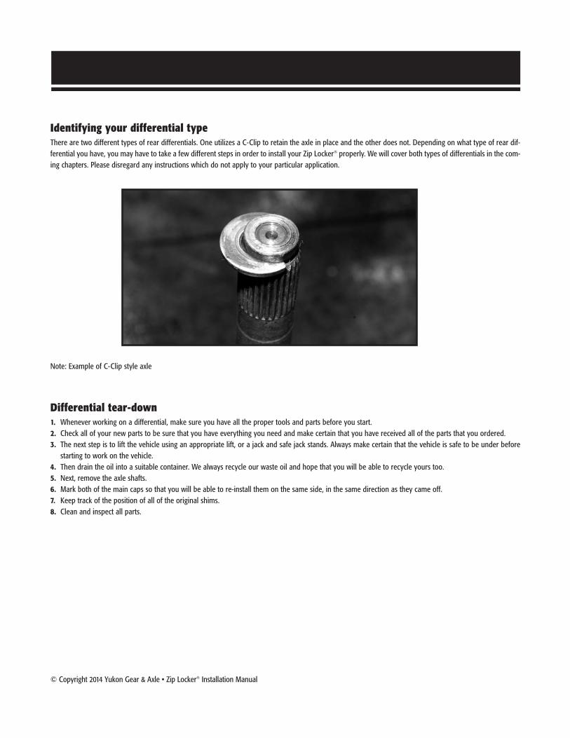
Identifying your differential typeThere are two different types of rear differentials. One utilizes a C-Clip to retain the axle in place and the other does not. Depending on what type of rear dif-ferential you have, you may have to take a few different steps in order to install your Zip Locker® properly. We will cover both types of differentials in the com-ing chapters. Please disregard any instructions which do not apply to your particular application.
Note: Example of C-Clip style axle
Differential tear-down1. Whenever working on a differential, make sure you have all the proper tools and parts before you start. 2. Check all of your new parts to be sure that you have everything you need and make certain that you have received all of the parts that you ordered.3. The next step is to lift the vehicle using an appropriate lift, or a jack and safe jack stands. Always make certain that the vehicle is safe to be under before
starting to work on the vehicle.4. Then drain the oil into a suitable container. We always recycle our waste oil and hope that you will be able to recycle yours too.5. Next, remove the axle shafts.6. Mark both of the main caps so that you will be able to re-install them on the same side, in the same direction as they came off.7. Keep track of the position of all of the original shims.8. Clean and inspect all parts.

2 Zip Locker® Installation Manual • © Copyright 2014 Yukon Gear & Axle
Removing carrier assemblyIMPORTANT: On some applications, a housing spreader will be necessary for carrier removal and installation.
• Remove both carrier bearing caps.• Use a housing spreader tool to spread the housing, if necessary.• Remove the carrier by pulling it forward.• If you used a housing spreader, be sure to release any pressure the tool is exerting once the carrier has been removed.• Do NOT use a housing spreader on aluminum housings as it will cause permanent damage to the housing.
• Inspect housing to ensure there is proper oil drainage in both axle tubes. Failure to do so could result in damage to your Zip Locker® in addition to oil leakage from axle seals.

© Copyright 2014 Yukon Gear & Axle • Zip Locker® Installation Manual 3
Removing carrier assembly (cont.)• If there is not a provision to ensure proper oil drainage, you will need to modify the housing. See photo below for proper oil drainage locations.
• If there is not a provision for a drainage slot on the upper right-hand side of the housing, then a hole may need to be drilled for clearance of the seal housing tube. This hole only needs to be created if there is not already proper clearance for the seal housing tube; this varies by application.
• Be sure to check your progress and clean up any debris, burrs, shavings, or rough edges created by modifying the housing.• Test the axle air vents to ensure they are working properly.
Installation of carrier bearings• Apply a thin layer of gear oil to the inside of the carrier bearings to help with the installation onto your Zip Locker® differential.• Press the carrier bearing onto the bearing journal of your Zip Locker® using a press. Make sure that you are aligning the bearing on squarely before
pressing it all the way down to the base of the bearing journal. Once it has been seated properly, flip the Zip Locker® over and repeat for the other side. NOTE: There should not be any shims under the bearing on the seal housing side. All Zip Lockers® will use outside carrier shims or side adjusters, if applicable.

4 Zip Locker® Installation Manual • © Copyright 2014 Yukon Gear & Axle
Setting backlashMeasurements will need to be taken off your old carrier in order to ensure proper installation of your Zip Locker®.
• Remove your ring & pinion from your old carrier after removing the ring gear bolts.• Place the old race over the bearing on the left hand side and use an accurate measurement tool to measure the distance from the ring gear deck to the
outside of the race. If your application used outside carrier shims to begin with, then take the measurement to the outside of the shims.
• Place your new race against your new bearing and take the same measurement. In order to set your backlash properly, you will need to add enough shimoutside the race to match the measurement off of your old carrier. In some instances, such as the Model 35, the original master shim may be requiredbetween the housing and the provided shims.
• Mount ring gear to Zip Locker® and torque ring gear bolts to proper specifications.
• Some OEM Dana Spicer® applications use 7/16” ring gear bolts. In this case, the flange holes on the Zip Locker® may need to be reamed from 3/8” to 7/16”.
MasterShimSmall
Shimsmeasure (xx.xxx inches)
Measuring Old Carrier Selecting Shims for Setting Backlash(after you have measured your old carrier)
© Copyright 2014 Yukon Gear & Axle • Zip Locker® Installation Manual 5
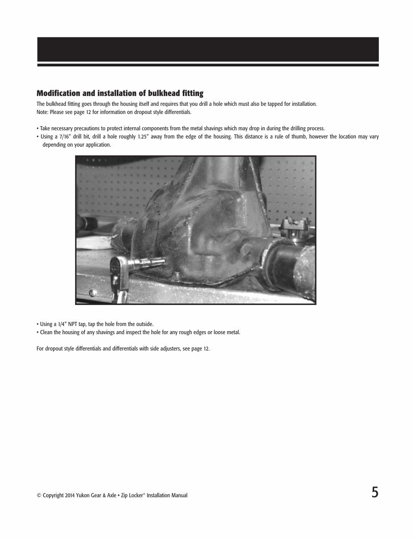
Modification and installation of bulkhead fittingThe bulkhead fitting goes through the housing itself and requires that you drill a hole which must also be tapped for installation.Note: Please see page 12 for information on dropout style differentials.
• Take necessary precautions to protect internal components from the metal shavings which may drop in during the drilling process.• Using a 7/16” drill bit, drill a hole roughly 1.25” away from the edge of the housing. This distance is a rule of thumb, however the location may vary
depending on your application.
• Using a 1/4” NPT tap, tap the hole from the outside.• Clean the housing of any shavings and inspect the hole for any rough edges or loose metal.
For dropout style differentials and differentials with side adjusters, see page 12.

6 Zip Locker® Installation Manual • © Copyright 2014 Yukon Gear & Axle
Seal housing installation
• Inspect all components, such as the seal housing and o-rings, for cleanliness. Make sure there is no debris to block the airway on the seal housing and check o-rings for any damage. Take a moment to cover the o-rings and seal housing surface with gear oil prior to assembly.
• Place the race over the bearing on the right-hand side of the Zip Locker®.• Place one of the provided master shims against the seal housing on the recessed face.• Slide the seal housing onto the Zip Locker®, taking care not to damage the o-rings.
A note on pinion head clearanceDue to variations in ring & pinion manufacturers, in some applications, the corner of the pinion gear may interfere with the Zip Locker® carrier. To fix this problem, you will need to grind some of the pinion head in order to gain the clearance you need.
This modification of the pinion head will not affect its performance or strength. The area you will be removing is usually well outside the contact pattern.

© Copyright 2014 Yukon Gear & Axle • Zip Locker® Installation Manual 7
Shimming carrier for proper preloadSeveral smaller shims will need to be placed next to the large master shim to ensure proper preload for your carrier bearings.
• To find this measurement, place the entire assembly into the housing and move it all the way to one side. • Using a set of calipers or a feeler gauge, measure the gap in-between the differential housing and the seal housing. A good amount of force will be needed
to get the assembly all the way over, thus giving you an accurate measurement. • Make sure you have the outside shims installed on the opposing side, which you took the measurements for earlier.
• Remove Zip Locker® carrier assembly and add the required shims next to the master shim. These shims should go between the seal housing and the mastershim. It is VERY important that the small shims go between the seal housing and the supplied master shim. If you place them against the bearing withoutthe supplied master shim it will cause the bearing to fail
NOTE: The required shims are determined by the measured gap plus additional shims for preload (see manufacturers recommendations for proper amountof preload shims).
• Install the entire assembly once again, with all the shims needed with the exception of the left hand side master shim, which will be installed last. Note: ifyou used a housing spreader before, you will want to spread the housing prior to this step.
• Rotate the seal housing to the proper position, with the tube in the center of the oil drainage provision.• Tap the left hand side master shim on the left hand side into place, being very careful not to damage it during installation. Release the tension on the
housing spreader, if you are using one.
Installing the bearing capsBefore you attempt to install the bearing caps, move the tube for the seal housing out of the way. Be gentle with it as it could break or kink if treated roughly.
• Install both carrier bearing caps by using the marking you made earlier to get each on its proper side.• Make sure that there is enough room between the seal housing tube and the cap before tightening down the caps. After this has been verified, torque the bolts down to their manufacturers recommended torque.
MasterShim
SmallShims
SealHousing
Shimming Carrier for Preload
8 Zip Locker® Installation Manual • © Copyright 2014 Yukon Gear & Axle
Adjusting BacklashAfter installing the pinion, adjust the backlash. A clear indication of pinion depth can only be obtained when the backlash is within, or very close to, specifi-cation. Backlash will typically change about 0.007” for each 0.010” that the carrier is moved. To decrease the backlash, move the carrier closer to the pinionby 0.010”. To increase the backlash by 0.007”, move the carrier away from the pinion gear by 0.010”. This is not exact for all ring & pinion sets, but it is agood general guideline.
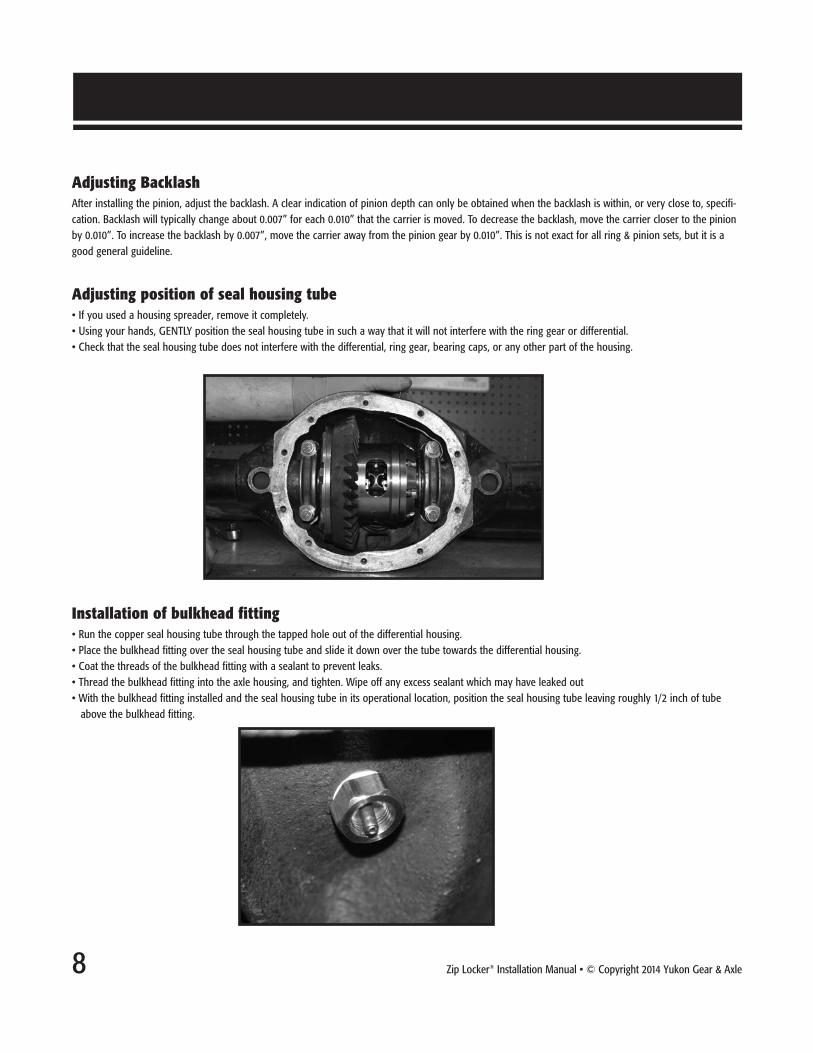
Adjusting position of seal housing tube• If you used a housing spreader, remove it completely.• Using your hands, GENTLY position the seal housing tube in such a way that it will not interfere with the ring gear or differential.• Check that the seal housing tube does not interfere with the differential, ring gear, bearing caps, or any other part of the housing.
Installation of bulkhead fitting• Run the copper seal housing tube through the tapped hole out of the differential housing.• Place the bulkhead fitting over the seal housing tube and slide it down over the tube towards the differential housing.• Coat the threads of the bulkhead fitting with a sealant to prevent leaks.• Thread the bulkhead fitting into the axle housing, and tighten. Wipe off any excess sealant which may have leaked out• With the bulkhead fitting installed and the seal housing tube in its operational location, position the seal housing tube leaving roughly 1/2 inch of tube above the bulkhead fitting.

© Copyright 2014 Yukon Gear & Axle • Zip Locker® Installation Manual 9
Installation of bulkhead fitting (cont.)• Slide the bulkhead o-ring over the seal housing tube and down into the bulkhead fitting.• Cut a small portion of nylon tube and insert it into one of the push-to-connect fittings.• With the portion of nylon tube installed, slide the push-to-connect fitting over the seal housing tube.• Thread the push-to-connect fitting into the bulkhead fitting, and lightly tighten torque between 25 and 35 inch pounds. • Remove the portion of nylon airline by depressing the top flange of the push-to-connect fitting and pulling out on the plastic air line.NOTE: The copper tube provided is longer than needed. You will need to cut it to the proper length once it has been determined.Warning: Only a small amount of torque is needed on the air fittings. Excessive torque will result in damage to the threads and o-ring.
Installation of the air systemNOTE: Verify all threads when using non-Yukon parts for replacement. • Remove one of the 1/8” BSP plugs from the compressor port. Apply Teflon tape or sealer to one of the 1/8” BSP nipples and thread into the port.• Tighten the fitting down and apply Teflon tape or sealer to the threads which face outward as well.• Attach the solenoid to the fitting and tighten down, making sure that the solenoid does not interfere with any other fittings on the compressor.• Apply Teflon tape or sealer to the 1/8” BSP push-to-connect fitting and tighten it into the solenoid outlet port.

10 Zip Locker® Installation Manual • © Copyright 2014 Yukon Gear & Axle
Notes on air supplyThe following air supply requirements must be met in order for the unit to work properly:
• Unit must maintain at least 85 PSI.• Unit must not exceed 110 PSI at any time.• Clean air must be provided as to not clog the air lines.• Solenoid must be mounted in relatively close proximity to the air supply.
Air linesDepending on the modifications to your vehicle, the path in which you run your air line will vary from application to application. However, there are somegeneral guidelines to take into account when running the air lines for your Zip Locker® differential.
• Try to keep the air line from dangling in such a way to where it may get caught on foreign objects such as rocks, branches, etc.• Keep the air line away from anything on the vehicle which could potentially damage it. Be sure to keep it away from hot objects such as exhaust and sharp objects which may puncture or cut it.
• Try to keep the line from kinking around objects which may result in blocking the air from getting to the locker.• Make sure to take suspension travel into account when running the air line to avoid the line getting pulled on .• Run the line all the way from the compressor to the housing before attaching or trimming it.
Connecting air line to bulkhead fitting• Start by connecting one end of the air line to the push-to-connect fitting on the solenoid. • After running the air line in a good route and securing it, trim it to the proper length with a sharp knife. • Insert the end of the airline into the push-to-connect fitting located on the differential.
NOTE: When cutting the plastic airline be sure to leave a flat square edge on the cut surface. A flat surface on the end of the air line will help ensure properengagement into the push-to-connect fittings. Firmly press the air line into the fitting until bottoming out. Test connection by pulling outward on the air lineensuring no movement takes place.

© Copyright 2014 Yukon Gear & Axle • Zip Locker® Installation Manual 11
Testing for leaksNOTE: Your vehicle should not be on during this testing period.
• Turn compressor on and allow the system to charge. Once charged, the compressor should not come back on while lockers are disengaged. If compressor does come back on, this would be an indication of a leak.
• Actuate the Zip Locker®(s) and wait to see if compressor recharges the tank. If the compressor comes back on within 10 minutes, you may have a leak in your system.
• If you believe you have a leak, spray all fittings with a solution of soap/water mixture and look for bubbles. If bubbles are present, try tightening the fitting and check to see if the leak persists. If bubbles are still present, disassemble the fitting in question and reapply Teflon tape or sealer.
Installing C-Clips To install the C-Clips into your axles, take the following steps:• Remove cross pin from the Zip Locker® by removing the cross pin bolt and pulling out retaining pin with the supplied retaining pin removal tool.
• Slide axle all the way into the differential, creating a gap between the C-Clip button and the side gear.• Insert C-Clip into the groove and pull the axle back out to seat the C-Clip into the recess in the side gear.• Follow this procedure on the second axle.• Install the Cross-Pin to retain the axle spacing.• Reinstall the retaining pin prior to the cross pin bolt.• Place thread-locker on the Cross-Pin retaining bolt prior to installing it and tightening it down to the manufacturer’s recommended torque.
NOTE: Some Zip Locker® applications fit both C-Clip and non-C-Clip axles. If you are using a C-Clip style Zip Locker® with non-C-Clip axles, simply insertthe retaining pin, apply thread locker to the retaining pin bolt, and tighten it down to the vehicle manufacturer’s recommended torque.
Testing your Zip Lockers®
During this testing phase, the vehicle should have its wheels off the ground, via jack stands or a lift, and the engine should remain off.
• Make sure that the vehicle is in neutral and the parking brake is not engaged.• Turn the ignition system on and activate the compressor to charge its tank.• Make sure the driveline is detained in some manner and rotate one wheel. The opposing wheel should rotate in the opposite direction.• Activate the Zip Locker® using activation switch. • Rotate the wheel again. At this point, both wheels should rotate together.• Turn the locker off and rotate the wheel again. The wheels should turn in opposite directions again.• Replace the differential cover, using a gasket or RTV silicone, and add the proper amount of gear oil to the differential.

12 Zip Locker® Installation Manual • © Copyright 2014 Yukon Gear & Axle
Drilling and tapping the bulkhead port
• Start off by removing all internal components from the housing and cleaning it thoroughly.• Start by marking a spot on the outside of the housing. The Toyota 8” dropouts have a spot on the side opposite the ring gear towards the top of the housing that is ideal. Other dropouts may vary, so make sure that the spot for the hole is clear of the ring gear, carrier, or any other obstructions that could interfere with the seal housing tube.
• Cover the pinion area to protect it from any shavings which could contaminate it as a result of the drilling and tapping.• Drill a 7/16” hole in the housing from the outside and tap it with a 1/4” NPT tap.• Clean the newly tapped hole and housing of any shavings or rough edges.
Setting backlash with side adjustors• Place the Zip Locker® into the housing and place the carrier caps in position, make sure that you use the markings you made earlier to get them on their correct sides.
• Tighten down the cap bolts by hand and thread the side adjustor on the ring gear side into place.• Tighten it down by hand until it will go no further. At this point there should be no backlash between the ring & pinion.• Back the adjustor out 1/4 turn.• Thread in the other adjustor with adjustor tool and tighten down.• Follow normal steps to adjust backlash.
Appendix for Dropout and Side Adjuster style differentials

© Copyright 2014 Yukon Gear & Axle • Zip Locker® Installation Manual 13
Seal housing installation
• Inspect all components, such as the seal housing and o-rings, for cleanliness. Make sure there are no debris to block the airway on the seal housing and check o-rings for any damage. Take a moment to cover the o-rings and seal housing surface with gear oil prior to assembly.
• Slide the seal housing onto the Zip Locker®, taking care not to damage the o-rings, and press it down until it is flat against the side adjuster.• Using a slight twisting motion while pressing the seal housing down onto the journal is advised to prevent damage to the o-rings.• Spin the seal housing until one of the two holes line up with side adjustor lock on the carrier bearing cap.• There are two different positions in which you can set the seal housing, depending on how you want to run the seal housing tube.
• Install the retaining clip as shown to keep the seal housing from rotating.• Verify the seal housing is locked in place by gently trying to rotate it.

14 Zip Locker® Installation Manual • © Copyright 2014 Yukon Gear & Axle
A Note on Aluminum IFS housings:Aluminum IFS housings must NOT be spread using a housing spreader tool. Usage of the tool could cause permanent and irreversible damage to the housing.
Preloading Aluminum housings• In order for the seal housing tube to clear in these applications, you must clear a groove in the factory shim on the right hand side. The groove should be close in size to the actual diameter of the tube itself.
• After grinding the notch, be sure that there are not any sharp edges which could damage the tube.• This shim will be installed in-between the housing and the seal housing. When installed, make sure the groove you cut lines up with the grooves in the seal housing and differential housing.
Shim Modification

© Copyright 2014 Yukon Gear & Axle • Zip Locker® Installation Manual 15
D60 Zip Locker Addendum - Revised Seal Housing Shim Stacking Configuration
Instructions:To properly shim the seal housing side of your D60 Zip Locker, please refer to the diagram below.
The 382S bearing race, thin shims, & seal housing must be stacked and oriented as shown. You will be using the thin shims included with your Zip Locker. • A minimum stack of 0.015” thin shims must be used to prevent the seal housing from bottoming out and contacting the bearing cone. A thick master shim isn’t required in the D60 design.
• To properly shim the opposite side of the D60 Zip Locker (ring gear side), use factory style “Under Bearing” shims. These shims fit between the bearing cone and the differential.
NOTE: Some later D60 axle assemblies are equipped with both “under bearing” shims and thick “outside” shims on the outside of the bearings. If youraxle is equipped with both, leave the outside shims in place when setting up your Zip Locker. A small notch may need to be cut in the factory outsideshim on the seal housing side to provide clearance for the copper tube.

16 Zip Locker® Installation Manual • © Copyright 2014 Yukon Gear & Axle
F10.25 Zip Locker Addendum - Shim Stacking Configuration
Instructions:To properly shim the seal housing side of your F10.25 Zip Locker, please refer to the diagram below.
The factory bearing, thin shims, thick master shim, & seal housing are stacked and oriented as shown. You will be using the thin shims and thick master shimincluded with your Zip Locker. • A minimum stack of 0.025” thin shims must be used to prevent the seal housing from bottoming out and contacting the bearing cone. A thick master shim is required in the F10.25 design and is included with your kit.
• To properly shim the opposite side of the F10.25 Zip Locker (ring gear side), use factory style “Outside Bearing” shims. These shims fit between the bearing race and vehicle housing.
NOTE: If your differential requires more than 0.050” of thin shims for set up, place additional shims on the outboardside of the seal housing. This will prevent the outside O-ring from coming off of the seal journal, causing an air leak.Remember to leave at least 0.025” of thin shims inboard, in addition to the thick master shim.

Warranty DetailsAll Zip Lockers® come with Yukon’s Best Warranty in the Business, a six (6) year warranty, including any collaterally damaged parts and
associated labor, up to $2,000, for the first two (2) years. Collaterally damaged parts must be submitted for inspection. Receipts for parts and
associated labor must be submitted as well. Only claims deemed reasonable by Yukon Gear & Axle will be accepted. Offer may be discontinued
without advance notice.
Yukon makes no other warranty of any kind, express or implied. All other warranties, including but not limited to an implied warranty of mer-
chantability or fitness for a particular purpose, are excluded. This warranty is offered provided that the Yukon product has been installed and main-
tained in accordance with Yukon instructions, and that it has not been subject to modification, accident, abnormal use or misuse. At Yukon’s discre-
tion, this warranty may be void if installation of Yukon product(s) occurs on vehicles with tires that exceed Yukon Maximum Recommended Tire
Size. Upon notification of a warranty claim, Yukon shall investigate the claim of defect, and, in the event of a verified defect, shall, at their sole choice,
either repair the defective product, replace it, or refund the purchase price.
Outside of the initial warranty program, this warranty does not cover, and Yukon shall not be liable for, incidental or consequential damages, includ-
ing loss of time, road service charges, labor charges, inconvenience, loss of vehicle use, loss of revenues, or loss or damage to personal property
(including loss or damage to vehicle parts due to the failure of the Yukon product). In addition, this warranty does not cover, and Yukon shall not
be liable for, any undertaking, representation, or agreements made by dealers or other third parties selling Yukon Gear & Axle products, except
where such agreements are within the provisions of this Warranty statement. Also, this warranty does not cover damage to the axle caused by or
facilitated by failure of a non-Yukon component. This agreement offers you specific legal rights. You may also have other rights which vary from
state to state.
For Your RecordsName:
Date:
Invoice # Yukon Part #
Yukon Maximum Recommended Tire Size Axle Style Max Tire Diameter Axle Style Max Tire Diameter
Dana 30 33 inches Toyota 16 35 inches
Dana M35 35 inches TLC - 30 35 inches
Dana 44 35 inches Ford 10.25 37 inches
Toyota 8 35 inches Dana 60 37 inches