zf as tronic technicians handbook
TRANSCRIPT
Technical manual
1328 765 101b

Technical manual
16 AS 260112 AS 2301 10 AS 2301
This technical manual serves as a technicalintroduction to the ZF-AS TRONIC system forvehicle and body manufacturers as well as ZFemployees.
The ZF standard application is described in thismanual. Customer-specific deviations must bedefined.
A ZF-AS TRONIC application contains thefollowing steps:
➢ Creation of a customer specification for the transmission by the vehicle manufacturer and ZF
➢ Documentation by ZF
➢ Initial installation
➢ Inspection of initial installation and commissioning by ZF staff
Please send your questions, comments andsuggestions for improvement directly to your contactin the technical sales department.
Subject to change
Copyright by ZF
This technical manual is protected by copyright.
Printed in Germany
Edition: 2000-09 Index b1999-12 Index a
Copyright by ZF
These repair instructions are protected by copyright. Any reproduction and dissemination in whatever form – also in adapted, paraphrased or extracted form – in particular as a reprint, photomechanical or electronic reproduction or as a storage in data-processing equipment or data networks without approval by the holder of the copyright is prohibited and will be prosecuted under civil and criminal law.
Printed in Germany

Table of contents
1 Brief description of the ZF-AS TRONIC
2 Transmission system and its components
3 Description of function
4 Installation
5 Annex
Table of contents
1 Brief description of the ZF-AS TRONIC
2 Transmission system and its components
2.1 System structure
2.2 Transmission and shift system2.2.1 Description of the transmission2.2.2 Description of the shift system2.2.3 Technical data 16 AS 2601 – direct drive2.2.4 Technical data 16 AS 2601 – overdrive2.2.5 Technical data 12 AS 2301 – direct drive2.2.6 Technical data 12 AS 2301 – overdrive2.2.7 Technical data 10 AS 2301 – direct drive2.2.8 Technical data 10 AS 2301 – overdrive
2.3 Transmission components2.3.1 Transmission actuator2.3.2 Clutch actuator
2.4 Peripheral components2.4.1 Range selector2.4.2 Electronic module (E module)2.4.3 Display
2.5 Auxiliary units2.5.1 Intarder2.5.1.1 General2.5.1.2 Mechanical interface2.5.1.3 Oil grades and oil fill quantities2.5.1.4 Coolant connection2.5.1.5 Pneumatic interface2.5.1.6 Electrical interface2.5.1.7 Communication interface2.5.2 PTO units2.5.2.1 Clutch-dependent PTO units2.5.2.2 Roadspeed-dependent PTO units2.5.2.3 Fitting at a later date
3 Function description
3.1 Operating modes
3.2 Automatic drive program3.2.1 Activating the automatic drive program3.2.2 Fully automatic gear changing3.2.3 Automatic selection of start gear3.2.4 Switching off the automatic drive program3.2.5 Re-activating the automatic drive program3.2.6 Manoeuvring3.2.6.1 Forward gears3.2.6.2 Reverse gears
Table of contents
3.3 System safety3.3.1 Principles3.3.2 Clutch concept3.3.3 Transmission control unit concept3.3.4 Interface concept3.3.5 Driving modes investigated
3.4 Responses to faults
3.5 Diagnosis
4 Installation
4.1 Transmission installation investigation4.1.1 Standard transmission installation drawings4.1.2 Installation drawings for PTO units + emergency steering pumps4.1.3 Input shafts4.1.4 Clutch bell housing4.1.5 Clutch4.1.6 Clutch release device4.1.7 Engine connection4.1.8 Mounting4.1.9 Transmission installation angle4.1.10 Propeller shaft connection4.1.11 Torsional vibrations4.1.12 Bending vibrations4.1.13 Cover / impact protection4.1.14 Additional brackets4.1.15 Fording ability4.1.16 Accessibility4.1.17 Additional guidelines for vehicle body manufacturer4.1.18 Vehicle wiring
4.2 Temperatures4.2.1 Permissible ambient temperatures on the transmission4.2.2 Permissible oil temperatures4.2.3 Causes of excess oil temperatures4.2.4 Additional transmission cooling4.2.5 Use at very low temperatures4.2.6 Storing the transmission at very low temperatures
4.3 Oil filling
4.4 The electrical system4.4.1 System layout and circuit diagrams4.4.2 Connector descriptions4.4.3 Operating voltages4.4.4 CAN bus installation4.4.5 Requirements placed on wiring quality4.4.6 Connector and counter connector designations4.4.7 Other electrical interfaces on the ZF-AS TRONIC4.4.8 CAN signals4.4.9 EMC compatibility
Table of contents
4.5 The pneumatic system
4.6 Additional units4.6.1 ZF-Intarder4.6.2 Externally produced retarders4.6.3 ZF PTO units4.6.4 Externally produced PTO units
4.7 Transmission installation on assembly line4.7.1 Transport4.7.2 Delivery of main transmission4.7.3 Anti-corrosion protection4.7.4 Painting at a later date4.7.5 Assembly of engine, clutch and transmission4.7.6 EOL programming4.7.7 Delivery monitoring
4.8 Additional information4.8.1 Operating and maintenance instructions4.8.2 Handing over vehicle to the end customer
4.9 Application and documentation4.9.1 Application4.9.2 ZF documentation4.9.3 Type plate4.9.4 Explanation of ZF documentation
5 Annex

1 Brief description of
ZF-AS TRONIC

1328 765 101 1-1 1999-12
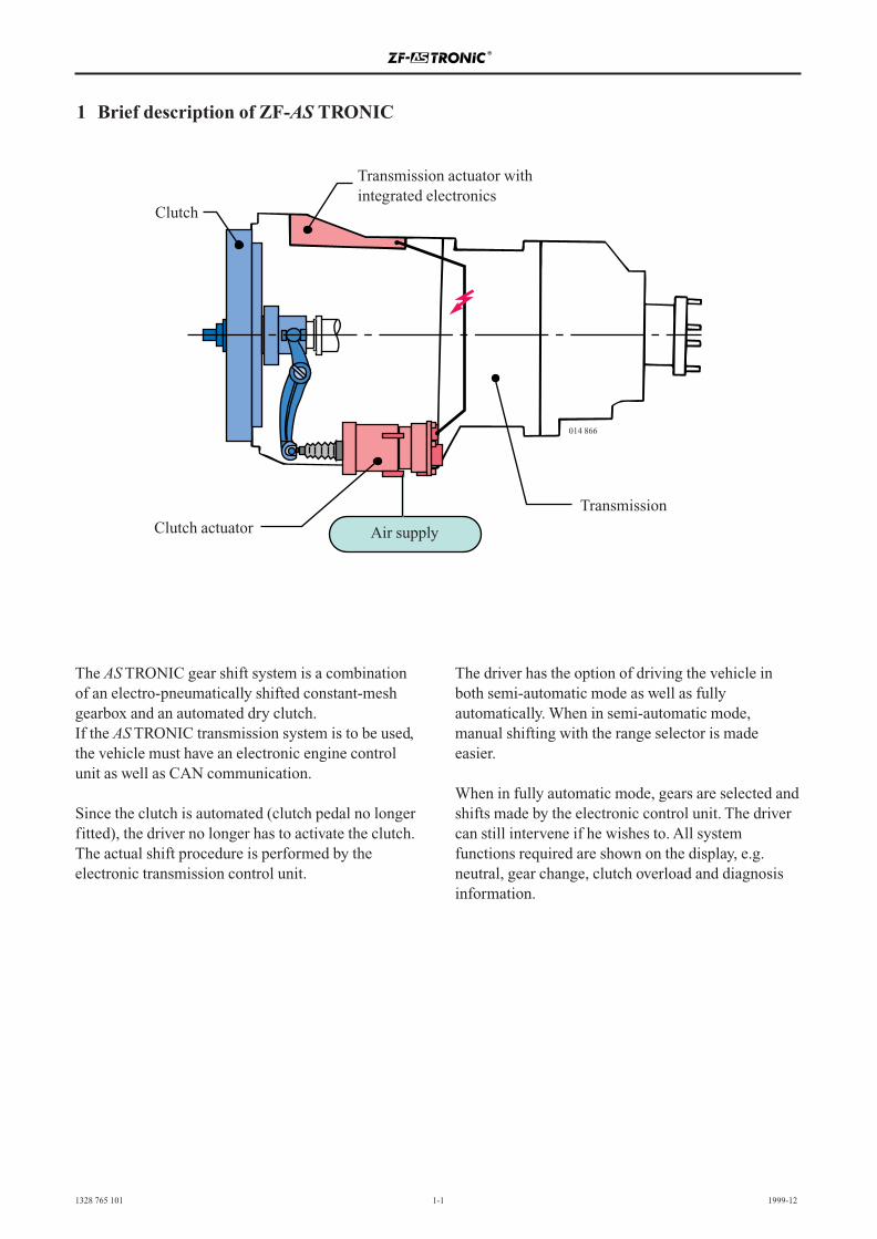
The AS TRONIC gear shift system is a combinationof an electro-pneumatically shifted constant-meshgearbox and an automated dry clutch.If the AS TRONIC transmission system is to be used,the vehicle must have an electronic engine controlunit as well as CAN communication.
Since the clutch is automated (clutch pedal no longerfitted), the driver no longer has to activate the clutch.The actual shift procedure is performed by theelectronic transmission control unit.
The driver has the option of driving the vehicle inboth semi-automatic mode as well as fullyautomatically. When in semi-automatic mode,manual shifting with the range selector is madeeasier.
When in fully automatic mode, gears are selected andshifts made by the electronic control unit. The drivercan still intervene if he wishes to. All systemfunctions required are shown on the display, e.g.neutral, gear change, clutch overload and diagnosisinformation.
014866
1 Brief description of ZF-AS TRONIC
Transmission actuator withintegrated electronics
Clutch
Clutch actuator
Transmission
Air supply
014 866

2 Transmission system
and its components
2.1 System structure
2.2 Transmission and shift system2.2.1 Description of the transmission2.2.2 Description of the shift system2.2.3 Technical data 16 AS 2601 – direct drive2.2.4 Technical data 16 AS 2601 – overdrive2.2.5 Technical data 12 AS 2301 – direct drive2.2.6 Technical data 12 AS 2301 – overdrive2.2.7 Technical data 10 AS 2301 – direct drive2.2.8 Technical data 10 AS 2301 – overdrive
2.3 Transmission components2.3.1 Transmission actuator2.3.2 Clutch actuator
2.4 Peripheral components2.4.1 Range selector2.4.2 Electronic module (E module)2.4.3 Display
2.5 Auxiliary units2.5.1 Intarder2.5.1.1 General2.5.1.2 Mechanical interface2.5.1.3 Oil grades and oil fill quantities2.5.1.4 Coolant connection2.5.1.5 Pneumatic interface2.5.1.6 Electrical interface2.5.1.7 Communication interface2.5.2 PTO units2.5.2.1 Clutch-dependent PTO units2.5.2.2 Roadspeed-dependent PTO units2.5.2.3 Fitting at a later date

2 Transmission system - components 2.1 System structure
1328 765 101 2-1 1999-12
2 Transmission system – components
2.1 System structure
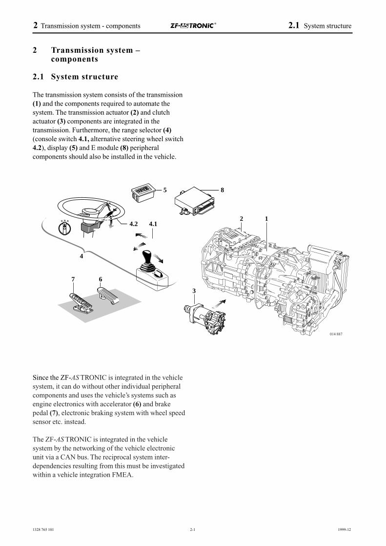
The transmission system consists of the transmission(1) and the components required to automate the system. The transmission actuator (2) and clutchactuator (3) components are integrated in thetransmission. Furthermore, the range selector (4)(console switch 4.1, alternative steering wheel switch4.2), display (5) and E module (8) peripheralcomponents should also be installed in the vehicle.
Since the ZF-AS TRONIC is integrated in the vehiclesystem, it can do without other individual peripheralcomponents and uses the vehicle’s systems such asengine electronics with accelerator (6) and brakepedal (7), electronic braking system with wheel speedsensor etc. instead.
The ZF-AS TRONIC is integrated in the vehicle system by the networking of the vehicle electronicunit via a CAN bus. The reciprocal system inter-dependencies resulting from this must be investigatedwithin a vehicle integration FMEA.
4
4.2 4.12
5
7 6
8
1
3
014 887
1328 765 101 2-2 1999-12
2.2 Transmission and shift system
2.2.1 Description of the transmission
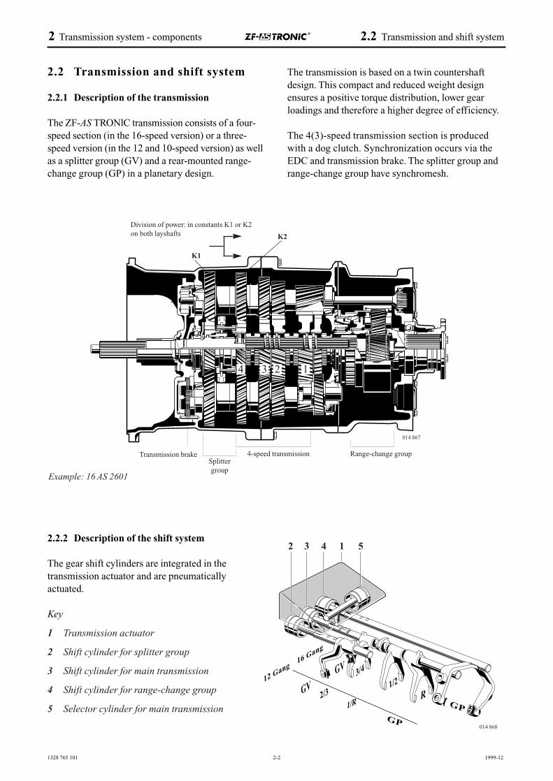
The ZF-AS TRONlC transmission consists of a four-speed section (in the 16-speed version) or a three-speed version (in the 12 and 10-speed version) as wellas a splitter group (GV) and a rear-mounted range-change group (GP) in a planetary design.
The transmission is based on a twin countershaftdesign. This compact and reduced weight designensures a positive torque distribution, lower gearloadings and therefore a higher degree of efficiency.
The 4(3)-speed transmission section is producedwith a dog clutch. Synchronization occurs via theEDC and transmission brake. The splitter group andrange-change group have synchromesh.
2 Transmission system - components 2.2 Transmission and shift system
2.2.2 Description of the shift system
The gear shift cylinders are integrated in thetransmission actuator and are pneumaticallyactuated.
Key
1 Transmission actuator
2 Shift cylinder for splitter group
3 Shift cylinder for main transmission
4 Shift cylinder for range-change group
5 Selector cylinder for main transmission
Example: 16 AS 2601
3/4
GP
1/2
2/3 R1/R
GP
GV
GV
16 Gang
12 Gang
1 2 3 4 52 3 4 1 5
Division of power: in constants K1 or K2on both layshafts
Transmission brake
1234
4-speed transmissionSplittergroup
Range-change group
K1
K2
014 867
014 868
1328 765 101 2-3 2000-09
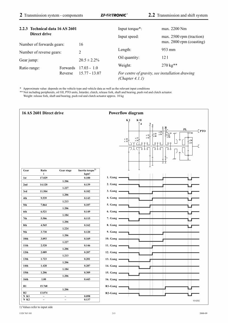
2.2.3 Technical data 16 AS 2601Direct drive
Number of forwards gears: 16
Number of reverse gears: 2
Gear jump: 20.5 ± 2.2%
Ratio range: Forwards 17.03 - 1.0Reverse 15.77 - 13.07
Input torque*: max. 2200 Nm
Input speed: max. 2500 rpm (traction)max. 2800 rpm (coasting)
Length: 953 mm
Oil quantity: 12 l
Weight: 270 kg**
For centre of gravity, see installation drawing (Chapter 4.1.1)
2 Transmission system - components 2.2 Transmission and shift system
* Approximate value: depends on the vehicle type and vehicle data as well as the relevant input conditions** Not including peripherals, oil fill, PTO units, Intarder, clutch, release fork, shaft and bearing, push rod and clutch actuator.
Weight: release fork, shaft and bearing, push rod and clutch actuator approx. 10 kg
16 AS 2601 Direct drive Powerflow diagram
Gear Ratio Gear stage Inertia torque1)
i kgm2
1st 17.029 0.1001.206
2nd 14.120 0.1391.227
3rd 11.504 0.1021.206
4th 9.539 0.1431.213
5th 7.864 0.1071.206
6th 6.521 0.1491.184
7th 5.506 0.1151.206
8th 4.565 0.1621.224
9th 3.730 0.1201.206
10th 3.093 0.1691.227
11th 2.520 0.1461.206
12th 2.089 0.2071.213
13th 1.723 0.2011.206
14th 1.428 0.2871.184
15th 1.206 0.3091.206
16th 1.00 0.443
R1 15.7681.206
R2 13.074N K1 – – 0.098N K2 – – 0.137
1) Values refer to input side
1328 765 101 2-4 2000-09
2 Transmission system - components 2.2 Transmission and shift system
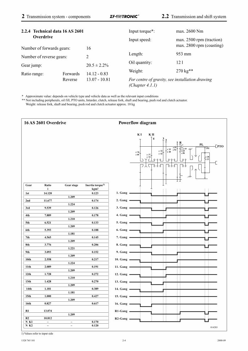
2.2.4 Technical data 16 AS 2601Overdrive
Number of forwards gears: 16
Number of reverse gears: 2
Gear jump: 20.5 ± 2.2%
Ratio range: Forwards 14.12 - 0.83Reverse 13.07 - 10.81
Input torque*: max. 2600 Nm
Input speed: max. 2500 rpm (traction)max. 2800 rpm (coasting)
Length: 953 mm
Oil quantity: 12 l
Weight: 270 kg**
For centre of gravity, see installation drawing(Chapter 4.1.1)
* Approximate value: depends on vehicle type and vehicle data as well as the relevant input conditions** Not including peripherals, oil fill, PTO units, Intarder, clutch, release fork, shaft and bearing, push rod and clutch actuator.
Weight: release fork, shaft and bearing, push rod and clutch actuator approx. 10 kg
16 AS 2601 Overdrive Powerflow diagram
Gear Ratio Gear stage Inertia torque1)
i kgm2
1st 14.120 0.1231.209
2nd 11.677 0.1741.224
3rd 9.539 0.1261.209
4th 7.889 0.1781.210
5th 6.521 0.1331.209
6th 5.393 0.1881.181
7th 4.565 0.1451.209
8th 3.776 0.2061.221
9th 3.093 0.1521.209
10th 2.558 0.2171.224
11th 2.089 0.1911.209
12th 1.728 0.2721.210
13th 1.428 0.2701.209
14th 1.181 0.3891.181
15th 1.000 0.4271.209
16th 0.827 0.617
R1 13.0741.209
R2 10.812N K1 – – 0.170N K2 – – 0.120
1) Values refer to input side
z 40
1328 765 101 2-5 2000-09
2 Transmission system - components 2.2 Transmission and shift system
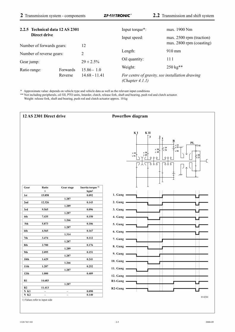
2.2.5 Technical data 12 AS 2301Direct drive
Number of forwards gears: 12
Number of reverse gears: 2
Gear jump: 29 ± 2.5%
Ratio range: Forwards 15.86 - 1.0Reverse 14.68 - 11.41
Input torque*: max. 1900 Nm
Input speed: max. 2500 rpm (traction)max. 2800 rpm (coasting)
Length: 910 mm
Oil quantity: 11 l
Weight: 250 kg**
For centre of gravity, see installation drawing (Chapter 4.1.1)
* Approximate value: depends on vehicle type and vehicle data as well as the relevant input conditions** Not including peripherals, oil fill, PTO units, Intarder, clutch, release fork, shaft and bearing, push rod and clutch actuator.
Weight: release fork, shaft and bearing, push rod and clutch actuator approx. 10 kg
12 AS 2301 Direct drive Powerflow diagram
Gear Ratio Gear stage Inertia torque 1)
i kgm2
1st 15.858 0.0921.287
2nd 12.326 0.1431.289
3rd 9.565 0.0961.287
4th 7.435 0.1501.266
5th 5.873 0.1061.287
6th 4.565 0.1671.314
7th 3.474 0.1121.287
8th 2.700 0.1761.289
9th 2.095 0.1511.287
10th 1.629 0.2411.266
11th 1.287 0.2521.287
12th 1.000 0.409
R1 14.6831.287
R2 11.413N K1 – – 0.090N K2 – – 0.140
z 36
1) Values refer to input side
1328 765 101 2-6 2000-09
2 Transmission system - components 2.2 Transmission and shift system
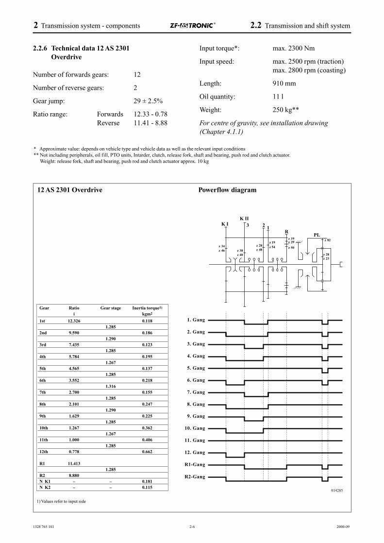
2.2.6 Technical data 12 AS 2301Overdrive
Number of forwards gears: 12
Number of reverse gears: 2
Gear jump: 29 ± 2.5%
Ratio range: Forwards 12.33 - 0.78Reverse 11.41 - 8.88
Input torque*: max. 2300 Nm
Input speed: max. 2500 rpm (traction)max. 2800 rpm (coasting)
Length: 910 mm
Oil quantity: 11 l
Weight: 250 kg**
For centre of gravity, see installation drawing(Chapter 4.1.1)
* Approximate value: depends on vehicle type and vehicle data as well as the relevant input conditions** Not including peripherals, oil fill, PTO units, Intarder, clutch, release fork, shaft and bearing, push rod and clutch actuator.
Weight: release fork, shaft and bearing, push rod and clutch actuator approx. 10 kg
12 AS 2301 Overdrive Powerflow diagram
Gear Ratio Gear stage Inertia torque1)
i kgm2
1st 12.326 0.1181.285
2nd 9.590 0.1861.290
3rd 7.435 0.1231.285
4th 5.784 0.1951.267
5th 4.565 0.1371.285
6th 3.552 0.2181.316
7th 2.700 0.1551.285
8th 2.101 0.2471.290
9th 1.629 0.2251.285
10th 1.267 0.3621.267
11th 1.000 0.4061.285
12th 0.778 0.662
R1 11.4131.285
R2 8.880N K1 – – 0.181N K2 – – 0.115
1) Values refer to input side
1328 765 101 2-7 2000-09
2 Transmission system - components 2.2 Transmission and shift system
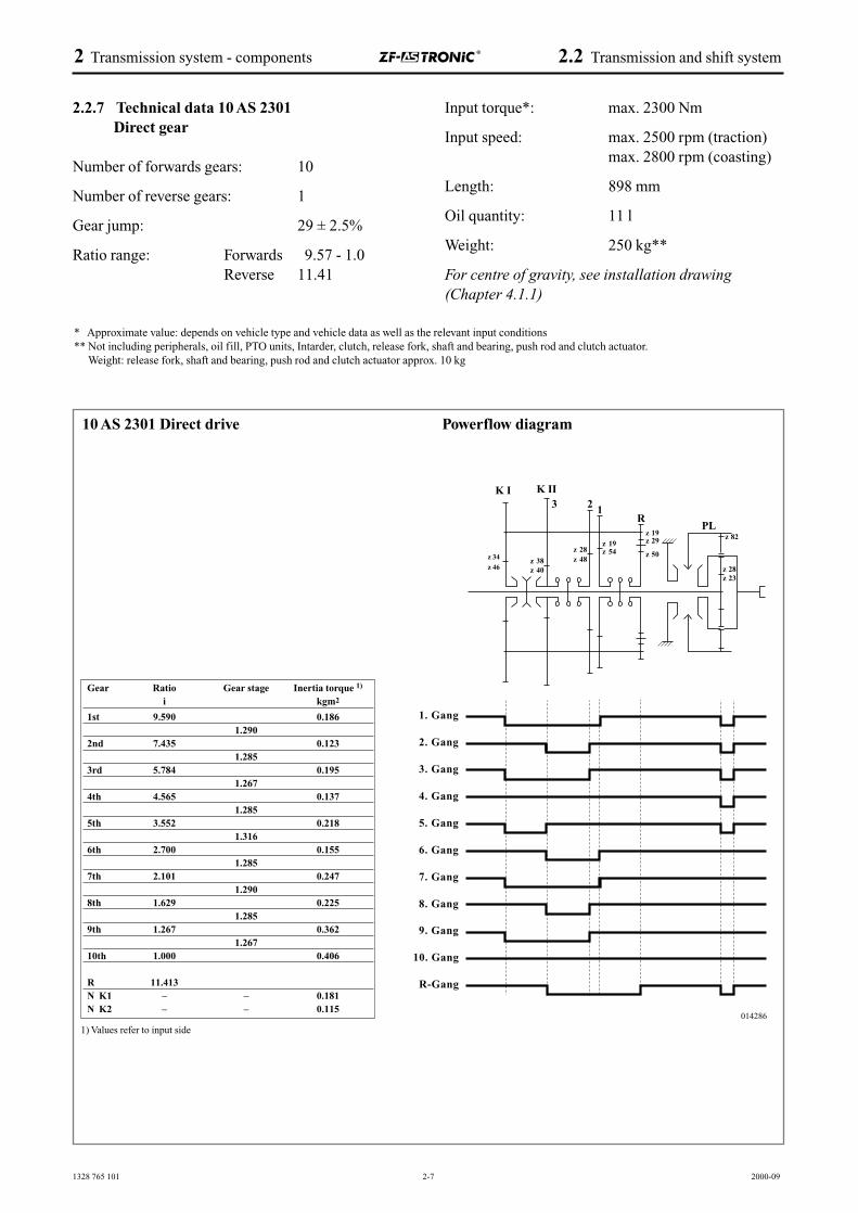
2.2.7 Technical data 10 AS 2301Direct gear
Number of forwards gears: 10
Number of reverse gears: 1
Gear jump: 29 ± 2.5%
Ratio range: Forwards 9.57 - 1.0Reverse 11.41
Input torque*: max. 2300 Nm
Input speed: max. 2500 rpm (traction)max. 2800 rpm (coasting)
Length: 898 mm
Oil quantity: 11 l
Weight: 250 kg**
For centre of gravity, see installation drawing (Chapter 4.1.1)
* Approximate value: depends on vehicle type and vehicle data as well as the relevant input conditions** Not including peripherals, oil fill, PTO units, Intarder, clutch, release fork, shaft and bearing, push rod and clutch actuator.
Weight: release fork, shaft and bearing, push rod and clutch actuator approx. 10 kg
10 AS 2301 Direct drive Powerflow diagram
Gear Ratio Gear stage Inertia torque 1)
i kgm2
1st 9.590 0.1861.290
2nd 7.435 0.1231.285
3rd 5.784 0.1951.267
4th 4.565 0.1371.285
5th 3.552 0.2181.316
6th 2.700 0.1551.285
7th 2.101 0.2471.290
8th 1.629 0.2251.285
9th 1.267 0.3621.267
10th 1.000 0.406
R 11.413N K1 – – 0.181N K2 – – 0.115
1) Values refer to input side
z 34
z 46

1328 765 201 2-8 2000-09
2 Transmission system - components 2.2 Transmission and shift system
2.2.8 Technical data 10 AS 2301Overdrive
Number of forwards gears: 10
Number of reverse gears: 1
Gear jump: 29 ± 2.5%
Ratio range: Forwards 7.44 - 0.78Reverse 11.41
Input torque*: max. 2300 Nm (OD)
Input speed: max. 2500 rpm (traction)max. 2800 rpm (coasting)
Length: 898 mm
Oil quantity: 11 l
Weight: 250 kg**
For centre of gravity, see installation drawing (Chapter 4.1.1)
* Approximate value: depends on vehicle type and vehicle data as well as the relevant input conditions** Not including peripherals, oil fill, PTO units, Intarder, clutch, release fork, shaft and bearing, push rod and clutch actuator.
Weight: release fork, shaft and bearing, push rod and clutch actuator approx. 10 kg
10 AS 2301 Overdrive Powerflow diagram
Gear Ratio Gear stage Inertia torque 1)
i kgm2
1st 7.435 0.1231.285
2nd 5.784 0.1951.267
3rd 4.565 0.1371.285
4th 3.552 0.2181.316
5th 2.700 0.1551.285
6th 2.101 0.2471.290
7th 1.629 0.2251.285
8th 1.267 0.3621.267
9th 1.000 0.4061.285
10th 0.778 0.662
R 11.413N K1 – – 0.181N K2 – – 0.115
1) Values refer to input side
1328 765 101 2-9 1999-12
2.3 Transmission components
2.3.1 Transmission actuator
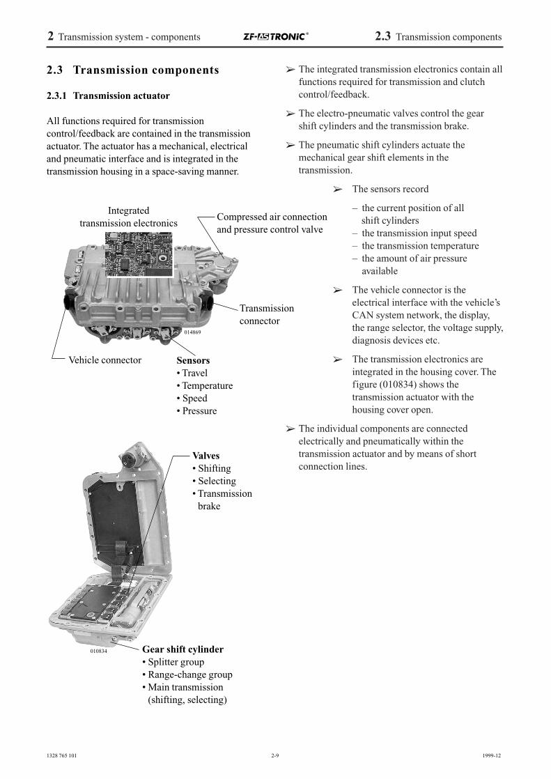
All functions required for transmissioncontrol/feedback are contained in the transmissionactuator. The actuator has a mechanical, electricaland pneumatic interface and is integrated in thetransmission housing in a space-saving manner.
➢ The integrated transmission electronics contain allfunctions required for transmission and clutchcontrol/feedback.
➢ The electro-pneumatic valves control the gearshift cylinders and the transmission brake.
➢ The pneumatic shift cylinders actuate the mechanical gear shift elements in thetransmission.
➢ The sensors record
– the current position of allshift cylinders
– the transmission input speed– the transmission temperature– the amount of air pressure
available
➢ The vehicle connector is the electrical interface with the vehicle’sCAN system network, the display,the range selector, the voltage supply,diagnosis devices etc.
➢ The transmission electronics areintegrated in the housing cover. Thefigure (010834) shows the transmission actuator with the housing cover open.
➢ The individual components are connected electrically and pneumatically within the transmission actuator and by means of short connection lines.
2 Transmission system - components 2.3 Transmission components
010834
014869
Integrated transmission electronics
Compressed air connectionand pressure control valve
Transmissionconnector
Vehicle connector Sensors• Travel• Temperature• Speed• Pressure
Valves• Shifting• Selecting• Transmission
brake
Gear shift cylinder• Splitter group• Range-change group• Main transmission
(shifting, selecting)
1328 765 101 2-10 2000-09
2 Transmission system - components 2.3 Transmission components
Actuationpiston
Electronicmodule
Travelsensor
Valves for clutch open
Valves for clutch closed
014871
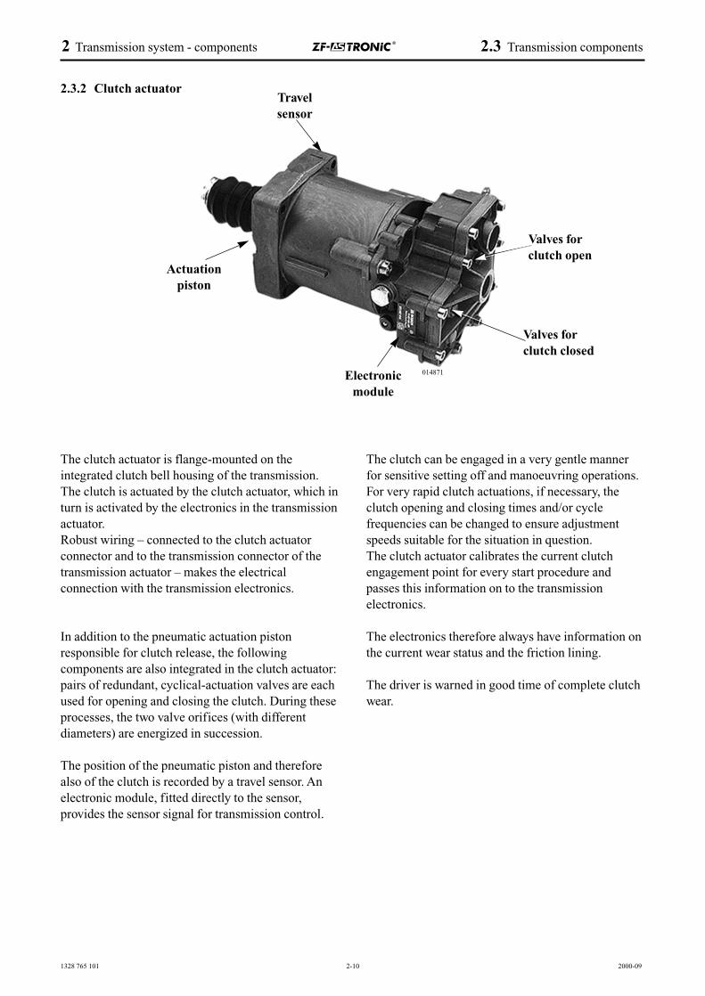
2.3.2 Clutch actuator
The clutch actuator is flange-mounted on the integrated clutch bell housing of the transmission.The clutch is actuated by the clutch actuator, which inturn is activated by the electronics in the transmissionactuator. Robust wiring – connected to the clutch actuator connector and to the transmission connector of thetransmission actuator – makes the electrical connection with the transmission electronics.
In addition to the pneumatic actuation piston responsible for clutch release, the following components are also integrated in the clutch actuator: pairs of redundant, cyclical-actuation valves are eachused for opening and closing the clutch. During theseprocesses, the two valve orifices (with different diameters) are energized in succession.
The position of the pneumatic piston and thereforealso of the clutch is recorded by a travel sensor. Anelectronic module, fitted directly to the sensor, provides the sensor signal for transmission control.
The clutch can be engaged in a very gentle mannerfor sensitive setting off and manoeuvring operations. For very rapid clutch actuations, if necessary, theclutch opening and closing times and/or cycle frequencies can be changed to ensure adjustmentspeeds suitable for the situation in question.The clutch actuator calibrates the current clutchengagement point for every start procedure and passes this information on to the transmission electronics.
The electronics therefore always have information onthe current wear status and the friction lining.
The driver is warned in good time of complete clutchwear.
1328 765 101 2-11 2000-09
2.4 Peripheral components
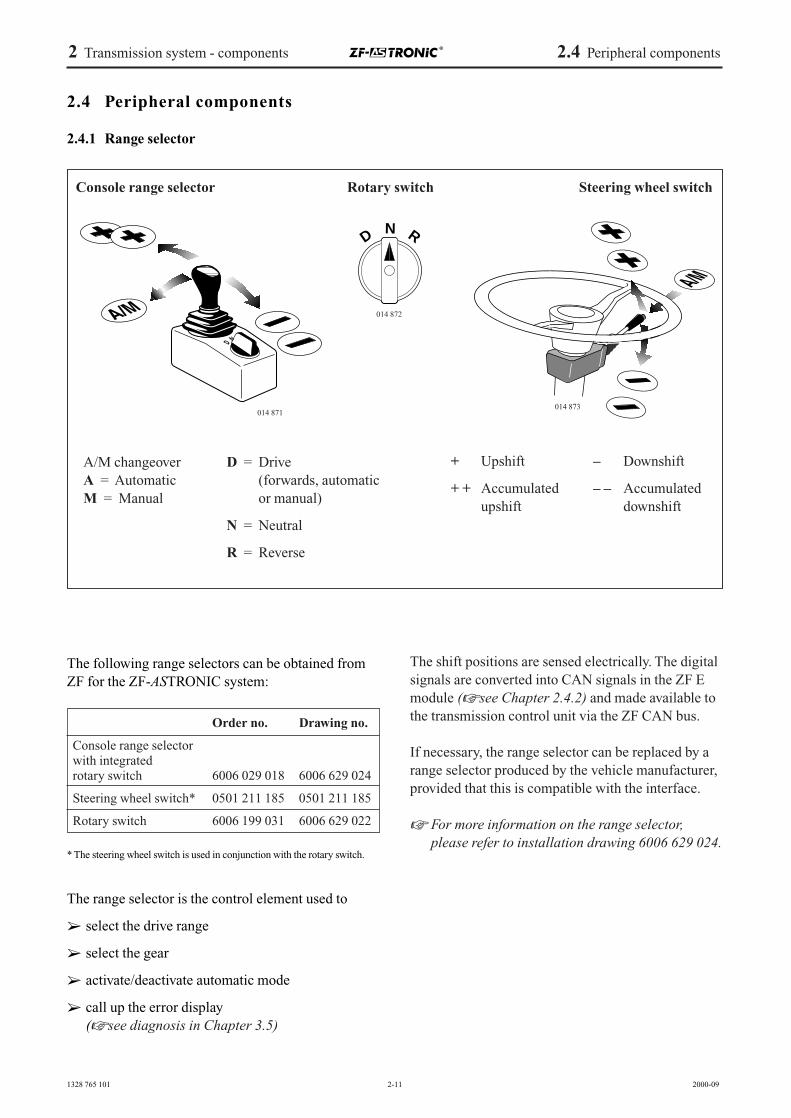
2.4.1 Range selector
The following range selectors can be obtained fromZF for the ZF-ASTRONIC system:
* The steering wheel switch is used in conjunction with the rotary switch.
The range selector is the control element used to
➢ select the drive range
➢ select the gear
➢ activate/deactivate automatic mode
➢ call up the error display (☞ see diagnosis in Chapter 3.5)
The shift positions are sensed electrically. The digitalsignals are converted into CAN signals in the ZF Emodule (☞ see Chapter 2.4.2) and made available tothe transmission control unit via the ZF CAN bus.
If necessary, the range selector can be replaced by arange selector produced by the vehicle manufacturer,provided that this is compatible with the interface.
☞ For more information on the range selector,please refer to installation drawing 6006 629 024.
2 Transmission system - components 2.4 Peripheral components
Console range selector Steering wheel switch
+ Upshift
+ + Accumulated upshift
– Downshift
– – Accumulateddownshift
D = Drive (forwards, automaticor manual)
N = Neutral
R = Reverse
A/M changeoverA = AutomaticM = Manual
014 871014 873
014 872
DN R
Rotary switch
Order no. Drawing no.
Console range selector with integrated rotary switch 6006 029 018 6006 629 024
Steering wheel switch* 0501 211 185 0501 211 185
Rotary switch 6006 199 031 6006 629 022
1328 765 101 2-12 1999-12
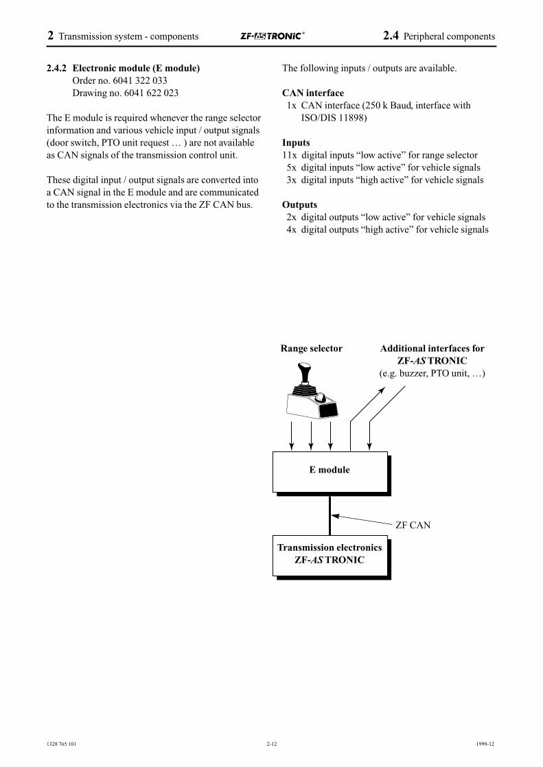
2.4.2 Electronic module (E module) Order no. 6041 322 033Drawing no. 6041 622 023
The E module is required whenever the range selectorinformation and various vehicle input / output signals(door switch, PTO unit request … ) are not availableas CAN signals of the transmission control unit.
These digital input / output signals are converted intoa CAN signal in the E module and are communicatedto the transmission electronics via the ZF CAN bus.
The following inputs / outputs are available.
CAN interface1x CAN interface (250 k Baud, interface with
ISO/DIS 11898)
Inputs11x digital inputs “low active” for range selector5x digital inputs “low active” for vehicle signals3x digital inputs “high active” for vehicle signals
Outputs2x digital outputs “low active” for vehicle signals4x digital outputs “high active” for vehicle signals
2 Transmission system - components 2.4 Peripheral components
Range selector Additional interfaces for ZF-AS TRONIC
(e.g. buzzer, PTO unit, …)
E module
Transmission electronics ZF-AS TRONIC
ZF CAN
1328 765 101 2-13 2000-09
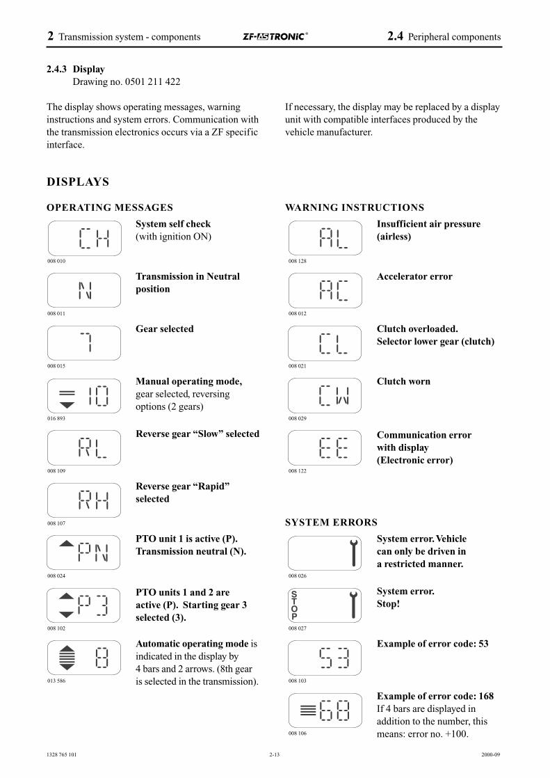
2.4.3 Display Drawing no. 0501 211 422
The display shows operating messages, warninginstructions and system errors. Communication withthe transmission electronics occurs via a ZF specificinterface.
DISPLAYS
OPERATING MESSAGES
If necessary, the display may be replaced by a displayunit with compatible interfaces produced by the vehicle manufacturer.
WARNING INSTRUCTIONS
SYSTEM ERRORS
2 Transmission system - components 2.4 Peripheral components
System self check(with ignition ON)
Transmission in Neutralposition
Gear selected
Manual operating mode,gear selected, reversingoptions (2 gears)
Reverse gear “Slow” selected
Reverse gear “Rapid”selected
PTO unit 1 is active (P).Transmission neutral (N).
PTO units 1 and 2 are active (P). Starting gear 3selected (3).
Automatic operating mode isindicated in the display by 4 bars and 2 arrows. (8th gear is selected in the transmission).
Insufficient air pressure (airless)
Accelerator error
Clutch overloaded.Selector lower gear (clutch)
Clutch worn
Communication error with display(Electronic error)
System error.Vehicle can only be driven in a restricted manner.
System error.Stop!
Example of error code: 53
Example of error code: 168If 4 bars are displayed inaddition to the number, thismeans: error no. +100.
008 010
008 011
008 015
008 109
008 107
008 024
008 102
013 586
008 128
008 012
008 021
008 029
008 122
008 026
008 027
008 106
008 103
016 893
1328 765 001 2-14 1999-12
2.5 Auxiliary units
2.5.1 Intarder
The Intarder is a hydrodynamic and therefore zero-wear transmission brake.
2.5.1.1 General
Please refer to the manual (order no. 6085 765 004)for an overview of system concept, layout, method of operation, operating elements, function variants,periphery and safety functions, as well as forinstallation and diagnosis instructions.
☞ A separate technical manual is available for theZF-Intarder (order no. 6085 765 004).
2.5.1.2 Mechanical interface
The Intarder is integrated in the ZF-AS TRONICtransmission. The Intarder can only be fitted at a laterdate if the transmission is converted. A decision onalso having the Intarder delivered must therefore bemade when ordering the ZF-AS TRONIC transmission.
The installation length between the SAE 1 flange and the output flange is the same as that in the ZF-AS TRONIC without the Intarder fitted.
☞ The installation length of the transmission shouldbe taken from the standard installation drawings(see Chapter 4.1).
An electronics unit supplied with the Intarder ishoused in the dry area of the vehicle (e.g. driver’scab).
☞ For more information, please refer to the ZF-Intarder technical manual, order no. 6085 765 004.
2.5.1.3 Oil grades and oil fill quantities
The Intarder and ZF-AS TRONIC transmission formthe common oil supply. The oil fill quantities areincreased as a result and can be taken from theIntarder technical manual (order no. 6085 765 004).
The ZF-AS TRONIC with integrated Intarder mayonly be filled with SAE 30 engine oil, semi-syntheticor fully synthetic oils.
☞ The list of lubricants TE-ML 02 (see Chapter 4.3)provides information on the exact oil specificationand the oil change intervals.
2.5.1.4 Coolant connection
An oil and water heat exchanger is fitted to theIntarder and this must be incorporated in the watercircuit of the engine cooling system.
☞ Please refer to the ZF-Intarder technical manual,order no. 6085 765 004 for more information.
2.5.1.5 Pneumatic interface
The air connection can either be made via the airboiler of the ZF-AS TRONIC transmission (☞ seeChapter 4.5) or via a separate connection on the airtank for auxiliary consumers.
☞ See information in ZF-Intarder technical manual,order no. 6085 765 004.
2.5.1.6 Electrical interface
The Intarder has an electrical interface with the vehicle wiring. There is no direct electrical connection with the ZF-AS TRONIC.
☞ Please refer to the ZF-Intarder technical manual6085 765 004 for the circuit diagrams and wiringplans of the various Intarder systems.
2 Transmission system - components 2.5 Auxiliary units
1328 765 101 2-15 1999-12
2.5.1.7 Communication interface
The Intarder electronics contain a CAN interface asspecified in SAE J 1939. Signals are exchanged viathis interface rather than via the vehicle’s other system-compatible electronic units.
☞ Please refer to the ZF-Intarder technical manual,order no. 6085 765 004 for the signal contentsand specifications.
2.5.1.8 Speedo signal
☞ When using the Intarder, the speedo signals shouldbe ensured in accordance with the informationprovided in the ZF-Intarder technical manual,order no. 6085 765 004.
2.5.2 PTO units
Engine-dependent PTO units are not available.
2.5.2.1 Clutch-dependent PTO units
The clutch-dependent PTO units can either be fittedin the workshop and supplied with the ZF-AS TRONICor can be fitted to the ZF-AS TRONIC at a later date.It should however be noted that the control unit of thecontrollable PTO units must be integrated in the ZF-AS TRONIC electrical system with its automated dryclutch.
☞ Please refer to the type sheet, order no. 1328 757 051, for an overview of the ZF PTOunits available with regard to permissible levels of torque and speeds attainable.
2.5.2.2 Roadspeed-dependent PTO units
The roadspeed-dependent PTO units (for additionalsteering pump or emergency steering pump) caneither be fitted in the workshop and supplied with theZF-AS TRONIC or can be fitted to the ZF-AS TRONICat a later date. The speed of these PTO units dependson the output speed of the ZF-AS TRONIC.
☞ For more information on this PTO unit, pleaserefer to the type sheet, order no. 1328 757 051.
2.5.2.3 Fitting at a later date
The PTO unit can be fitted at a later date. The transmission electronics unit must be adapted.
2 Transmission system - components 2.5 Auxiliary units

1328 765 101 1999-01
3 Function description
3.1 Operating modes
3.2 Automatic drive program3.2.1 Activating the automatic drive program3.2.2 Fully automatic gear changing3.2.3 Automatic selection of start gear3.2.4 Switching off the automatic drive program3.2.5 Re-activating the automatic drive program3.2.6 Manoeuvring3.2.6.1 Forwards gears3.2.6.2 Reverse gears
3.3 System safety3.3.1 Principles3.3.2 Clutch concept3.3.3 Transmission control unit concept3.3.4 Interface concept3.3.5 Driving modes investigated
3.4 Responses to faults
3.5 Diagnosis

3 Function description 3.1 Operating modes
1328 765 101 3-1 1999-12
3 Function description
3.1 Operating modes
The ZF-AS TRONIC transmission control unit issubdivided into operating modes (e.g.: setting off,manoeuvring, gear shifting while vehicle is inmotion, gear engagement while in motion, etc.) in ahierarchical manner. Defined functions of the ZF-AS TRONIC are assigned to each operating mode.
The operating modes are defined by clear sensor signals or by signals via the communication system.
☞ Please refer to the TKI “Shift functions and operating modes” (ZF no. 1328 761 019) for anoverview of the operating modes and their functions.
1328 765 101 3-2 1999-12
3 Function description 3.2 Automatic drive program
3.2 Automatic drive program
The automatic drive program of the ZF-AS TRONICallows the vehicle to be driven in a fully automaticmanner. To continue moving the vehicle, the driversimply has to actuate the accelerator and brake (service brake and 3rd brake). The automatic driveprogram is integrated in the electronics of the ASTRONIC transmission system.
3.2.1 Activating the automatic drive program
Once the electrical system has been switched on (byturning the ignition key) and the engine has beenstarted, the automatic drive program starts to operatewhen the driver activates the forwards travel range.
Once the parking brake has been released and theaccelerator has been depressed, the vehicle sets off.The fully automatic drive program determines whengears should be shifted and the gear into which shiftsshould be made.
3.2.2 Fully automatic gear changing
To adapt these fully automatic gear changes to thedrive situation in question and to do this in a fuel-efficient manner, numerous pieces of information fromthe transmission and other electronic systems are evaluated in the electronics of the transmission systemvia data communication.
☞ For detailed information on the signals used forthe drive programs, please refer to the interfacespecification 1328 761 005.
3.2.3 Automatic selection of start gear
When the automatic drive program is active, the startgear is calculated and selected fully automatically inaccordance with the setting off conditions (gradient,loads, etc.).
If the driver believes that the start gear, as shown inthe display, is too high, he can correct and lower thisusing the range selector (☞ for more information,refer to the functions of the range selector in Chapter2.4).
To extend the clutch service life, corrections cannotbe made into a higher gear.
A start gear will even be selected and engaged oncethe ignition has been switched off and the vehiclerestarted.
3.2.4 Switching off the automatic drive program
Should a critical drive situation arise and the driverwish to avoid automatic gear changing (retain a gear)or shift gear manually (manual drive mode), the automatic drive program can be switched off by actuating the range selector accordingly (☞ for moreinformation, refer to the functions of the range selector in Chapter 2.4).
This intervention can be made at any time when thevehicle is in motion. Appropriate failsafe mechanisms have been implemented to rule out therisk of the engine ever being overrevved.
If the automatic drive program is switched off and thevehicle moved through manual operation of the rangeselector, the fuel consumption levels may then risedepending on the manual gear selection made by thedriver.
Despite manual driving mode, the automatic startgear is retained as in the automatic drive program.
Should an error occur in the transmission system orin a data exchange with other systems, the automaticdrive program may switch itself off depending on theeffect of the error.
1328 765 101 3-3 1999-12
3 Function description 3.2 Automatic drive program
3.2.5 Re-activating the automatic drive program
The automatic drive program can be re-activated atany time when the vehicle is in motion. This is doneby operating the range selector accordingly.
☞ For more information, refer to the functions of therange selector in Chapter 2.4
3.2.6 Manoeuvring
3.2.6.1 Forwards gears
The manoeuvring gears are
➢ 1st, 2nd and 3rd gear in the 16 AS 2601,
➢ 1st and 2nd gear in the 12 AS 2301 and
➢ 1st gear in the 10 AS 2301 (bus)
In certain driving modes, the automatic start gearmay be in the same range as the manoeuvring gears.
If the system selects a start gear which is outside themanoeuvring range, the driver must change this to themanoeuvring gear desired by intervening manuallyon the range selector.
Automatic gear changes are not made when the vehicle is in the “Manoeuvring” operating mode. If achange into a lower gear is to be made duringmanoeuvres, this must be done manually via therange selector.
3.2.6.2 Reverse gears
In the ZF-AS TRONIC systems for truck applications16 AS 2601 and 12 AS 2301, the slower R gear isusually selected. As a rule, automatic gear changes donot occur in the reverse travel range – regardless ofthe accelerator position. The rapid R gear must beselected by manual intervention on the range selector.
When using the bus application (10 AS 2301), onlyone R gear is available.
☞ For more information on the issue of“Manoeuvring”, please refer to TKI 1328 761 019.
1328 765 101 3-4 1999-12
3.3 System safety
3.3.1 Principles
The principles behind the ZF-AS TRONIC systemsafety concept are the requirements made by theAutomobile Safety Act. The clutch and transmissionare not therefore considered as safety componentssuch as the brakes or steering systems. This meansthat the law does not believe that malfunctions causedby faults in the clutch or transmission can leaddirectly to safety-related malfunctions resulting inaccidents.
Since the ZF-AS TRONIC is however an automationsystem, which unlike conventional driveline components takes on some of the processes otherwisecontrolled by the driver, it is also assigned anincreased level of responsibility.
System analyses undertaken:
➢ risk analysis as specified in DIN 19250➢ system FMEA ➢ vehicle integration FMEA’s➢ K FMEA’s
The following situations have been defined as saferand those to be aimed for in instances of error:
➢ “driveline closed” when vehicle in motion➢ “driveline open” when vehicle at standstill
The following vehicle behaviour has been defined asrelevant to safety as a result of the system analyses:
➢ independent setting off➢ setting off in opposite direction of travel➢ blocked driveline when in motion
Special measures were undertaken during the development of the ZF-AS TRONIC (e.g redundancies, verification checks etc.) to avoid thesecircumstances wherever possible.Errors which do not lead to the drive behaviour listedabove will only influence agreed functions of the AS TRONIC and therefore the reliability and/or availability of the vehicle.
The system responses to simple faults are describedin a malfunction specification. Since the vehiclemanufacturer is responsible for vehicle responses,agreement is reached with the manufacturer onresponses to faults within the framework of a vehicleintegration FMEA. This includes vehicle faults whichmay have an effect on the ZF-AS TRONIC. The definition of the malfunction response is written inaccordance with the principles of the aforementioned system analyses.
High levels of reliability were even provided for inthe conception stage of the ZF-AS TRONIC (numberof components, integrated module, reduction in scopeof wiring).The function and service life of the mechanical andpneumatic components have been designed in accordance with state-of-the-art technology and triedand tested in various trials.
The defined nominal mode cannot be set if voltagefails or the air supply is suddenly interrupted during ashift. In such instances, the last mode is retained(extended duration is rare and probability of occurrence very low in accordance with riskographfrom DIN 19250).
3 Function description 3.3 System safety
1328 765 101 3-5 1999-12
3.3.2 Clutch concept
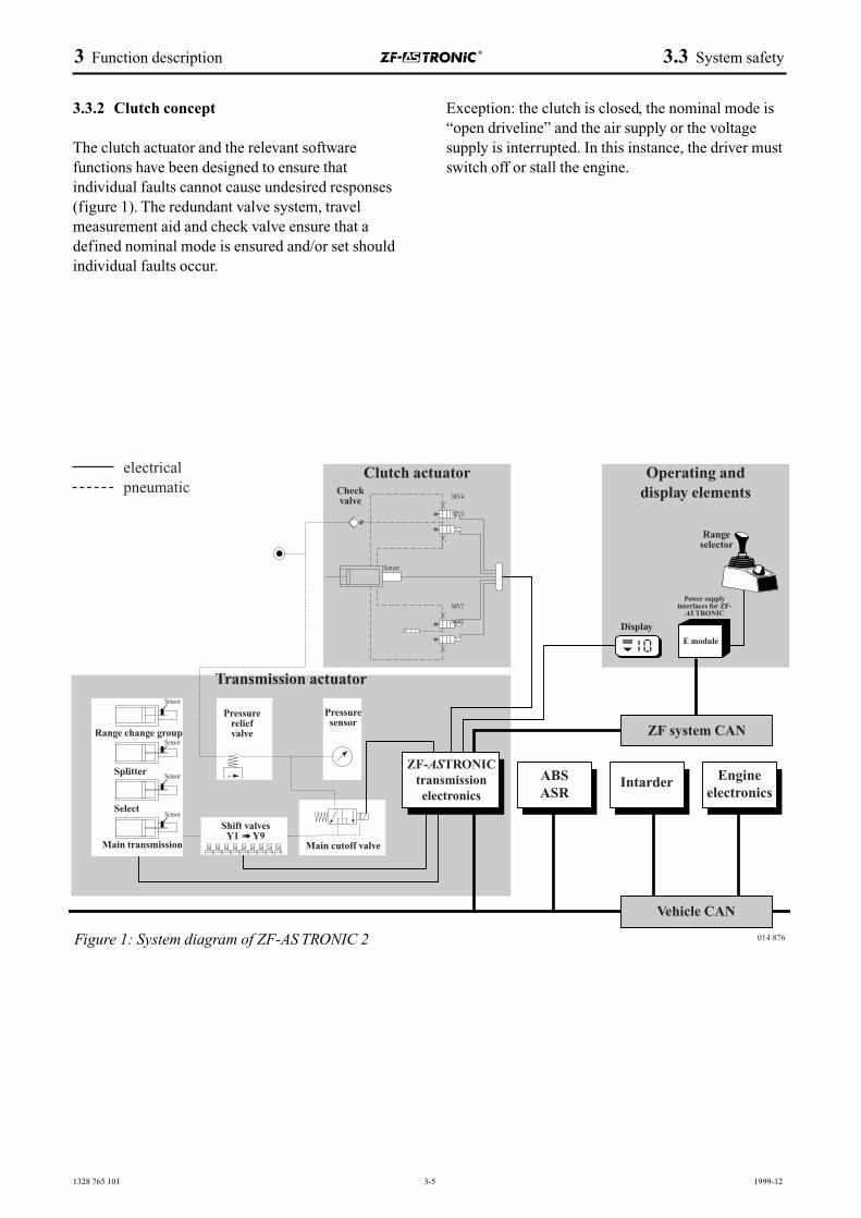
The clutch actuator and the relevant software functions have been designed to ensure that individual faults cannot cause undesired responses (figure 1). The redundant valve system, travelmeasurement aid and check valve ensure that adefined nominal mode is ensured and/or set shouldindividual faults occur.
Exception: the clutch is closed, the nominal mode is“open driveline” and the air supply or the voltagesupply is interrupted. In this instance, the driver mustswitch off or stall the engine.
3 Function description 3.3 System safety
Figure 1: System diagram of ZF-AS TRONIC 2
Clutch actuator Operating and display elements
ZF-ASTRONICtransmissionelectronics
ABSASR
Intarder Engineelectronics
ZF system CAN
Vehicle CAN
Transmission actuator
Checkvalve
Display
Power supply interfaces for ZF-
AS TRONIC
Range selector
E module
Pressurereliefvalve
Shift valvesY1 ➠ Y9
Main cutoff valve
Splitter
Range change group
Select
Main transmission
Pressuresensor
Sensor
Sensor
MV4
MV3
MV2
MV1
electricalpneumatic
Sensor
Sensor
Sensor
014 876
1328 765 101 3-6 1999-12
3.3.3 Transmission control concept
The transmission control unit is designed to ensurethat when a shift is triggered at least two valvesalways have to be shifted (central air and shift valve).The transmission position is permanently monitoredby a travel measuring system. The conventionaldesign of the transmission control unit (incl. functionsoftware) ensures that should individual faults arise,undesired shift processes cannot be triggered.
3.3.4 Interface concept
The interfaces between the ZF-AS TRONIC andvehicles are very important with regard to safety andavailability. Responses to faults and protective measures in the ZF-AS TRONIC should ensure thatthe nominal mode is retained or set should errors /faults arise. A “vehicle integration FMEA” is createdjointly with the vehicle manufacturer to test andensure this principle and, if necessary, any relevantmeasures are initiated.
3.3.5 Driving modes investigated
Error trees have been created for the following driving modes:
➢ independent setting off
➢ setting off in opposite direction of travel
➢ vehicle not setting off (gear already selected)
➢ driveline interruption during travel
➢ acceleration not OK
➢ blocked driveline during travel
The measures to be initiated ensure compliance withthe aforementioned criteria for behaviour in responseto errors and faults.
3 Function description 3.3 System safety
1328 765 101 3-7 1999-12
3.4 Responses to faults
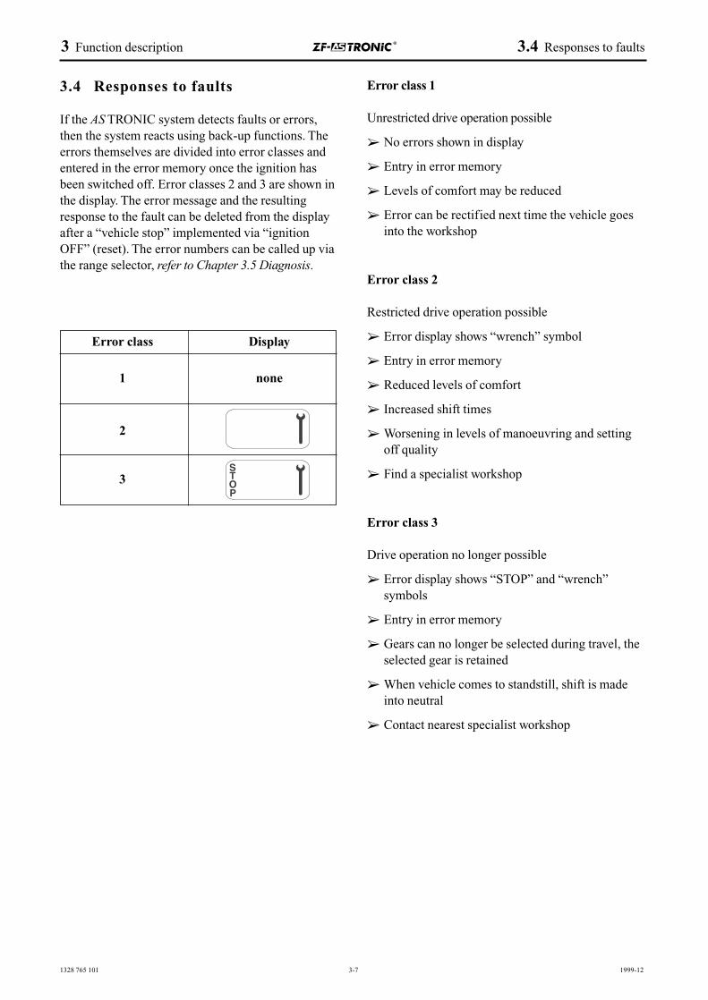
If the AS TRONIC system detects faults or errors,then the system reacts using back-up functions. Theerrors themselves are divided into error classes andentered in the error memory once the ignition hasbeen switched off. Error classes 2 and 3 are shown inthe display. The error message and the resultingresponse to the fault can be deleted from the displayafter a “vehicle stop” implemented via “ignitionOFF” (reset). The error numbers can be called up viathe range selector, refer to Chapter 3.5 Diagnosis.
Error class 1
Unrestricted drive operation possible
➢ No errors shown in display
➢ Entry in error memory
➢ Levels of comfort may be reduced
➢ Error can be rectified next time the vehicle goesinto the workshop
Error class 2
Restricted drive operation possible
➢ Error display shows “wrench” symbol
➢ Entry in error memory
➢ Reduced levels of comfort
➢ Increased shift times
➢ Worsening in levels of manoeuvring and settingoff quality
➢ Find a specialist workshop
Error class 3
Drive operation no longer possible
➢ Error display shows “STOP” and “wrench” symbols
➢ Entry in error memory
➢ Gears can no longer be selected during travel, theselected gear is retained
➢ When vehicle comes to standstill, shift is madeinto neutral
➢ Contact nearest specialist workshop
3 Function description 3.4 Responses to faults
Error class Display
1 none
2
3
1328 765 101 3-8 1999-12
3.5 Diagnosis
ZF diagnosis systems:
The following ZF diagnosis systems are available forthe ZF-AS TRONIC:
➢ TESTMAN, for description, refer to 6008 750 001 (ZF diagnosis system for PCapplications incl. ZF diagnosis adapter DPA 03and connection cable with ISO and/or SAEconnection)
➢ A terminal tester is available for electrical troubleshooting of input and output signals of thevehicle interface with the ZF-AS TRONIC. Thistester comes complete with an adapter for 20 or18-pin plug connections.
Communication:
The hardware interface is implemented as specifiedin
➢ ISO 14230-1
The following communication protocols are available
➢ ZF protocol
➢ keyword protocol 2000
– Data Link Layer Recommended Practice (Status: Version 1.1; Date: 31.1.1999)
– Implementation of Diagnostic Services Recommended Practice (Status: Version 1.5; Date: 1.10.1999)
The protocol is transmitted via the “K-line”.
ZF-AS TRONIC diagnosis specification:
☞ refer to TKI 6009 774 004
Error number displayon the ZF-AS TRONIC display:
If an error has occurred, the error number can becalled up on the display. If serious system errors(Stop +wrench) have occurred, the vehicle cannot bedriven any further.
To call up error messages, the rotary switch is positioned at neutral and the flick lever held in the +direction.
If the service brake is actuated at the same time, allthe errors stored in the error memory are displayed.
If the service brake is not actuated, only the errorscurrently in place are displayed.
3 Function description 3.5 Diagnosis

4 Installation
4.1 Transmission installation investigation4.1.1 Standard transmission installation drawings4.1.2 Installation drawings for PTO units + emergency steering pumps4.1.3 Input shafts4.1.4 Clutch bell housing4.1.5 Clutch4.1.6 Clutch release device4.1.7 Engine connection4.1.8 Mounting4.1.9 Transmission installation angle4.1.10 Propeller shaft connection4.1.11 Torsional vibrations4.1.12 Bending vibrations4.1.13 Cover / impact protection4.1.14 Additional brackets4.1.15 Fording ability4.1.16 Accessibility4.1.17 Additional guidelines for vehicle body manufacturer4.1.18 Vehicle wiring
4.2 Temperatures4.2.1 Permissible ambient temperatures on the transmission4.2.2 Permissible oil temperatures4.2.3 Causes of excess oil temperatures4.2.4 Additional transmission cooling4.2.5 Use at very low temperatures4.2.6 Storing the transmission at very low temperatures
4.3 Oil filling
4.4 The electrical system4.4.1 System layout and circuit diagrams4.4.2 Connector descriptions4.4.3 Operating voltages4.4.4 CAN bus installation4.4.5 Requirements placed on wiring quality4.4.6 Connector and mating connector designations
4.4.7 Other electrical interfaces on the ZF-AS TRONIC4.4.8 CAN signals4.4.9 EMC compatibility
4.5 The pneumatic system
4.6 Additional units4.6.1 ZF-Intarder4.6.2 Externally produced retarders4.6.3 ZF PTO units4.6.4 Externally produced PTO units
4.7 Transmission installation on assembly line4.7.1 Transport4.7.2 Delivery of main transmission4.7.3 Anti-corrosion protection4.7.4 Painting at a later date4.7.5 Assembly of engine, clutch and transmission4.7.6 EOL programming4.7.7 Delivery monitoring
4.8 Additional information4.8.1 Operating and maintenance instructions4.8.2 Handing over vehicle to end customer
4.9 Application and documentation4.9.1 Application4.9.2 ZF documentation4.9.3 Type plate4.9.4 Explanation of ZF documentation
4 Installation 4.1 Transmission installation investigation
1328 765 101 4-1 2000-09
4 Installation
4.1 Transmission installation investigation
4.1.1 Standard transmission installation drawings
Truck
12 AS 2301 1327 600 015
16 AS 2601 1328 600 015
12 AS 2301 IT(heat exchanger, rear left) 1327 600 016
16 AS 2601 IT(heat exchanger, rear left) 1328 600 016
Bus
10 AS 2301 IT(heat exchanger, rear right) 1327 600 007
4.1.2 Installation drawings for PTO units + emergency steering pumps
AS TRONIC with NAS/10 6091 607 003
AS TRONIC with NAS/PL 6091 615 0036091 615 005
AS TRONIC with NH/1 6090 601 018
AS TRONIC with NH/2 6090 602 015
AS TRONIC with NH/4 6090 604 010
4.1.3 Input shafts
The standard shaft is shown under 4.1.6.
An additional charge will be made for the supply ofother input shafts.
4.1.4 Clutch bell housing
The AS TRONIC has an integrated clutch bellhousing. The AS TRONIC can therefore only besupplied with an SAE1 engine connection. (☞ forconnection dimensions, see installation drawing).
Fastening to the flywheel housing
➢ Use very strong (8.8) screws
➢ Use shims as specified in DIN 125
➢ Observe the tightening torques specifiedM10 46 ± 5 NmM12 79 ± 8 Nm
CAUTIONDo not use toothed locking screws.
Fastening with stud boltsIf the AS TRONIC is fastened by threaded pinsattached to the flywheel housing on the engine side,the stud bolts must not protrude by more than 62 mm.Reason: if they protrude by a greater distance than thatspecified, it is very difficult to dismantle thetransmission actuator during servicing. In extremecases, the transmission has to be removed before theactuator can be dismantled.
4.1.5 Clutch
Drawn clutches may only be used if they are torsiondampened and if they have been deemed suitable forthe engine transmission combination in question. Payparticular attention to the increased clutch service lifeassociated with the AS TRONIC.
Standard:1 - disc clutch, max. diameter 430 mm
Optional:2 - disc clutch, max. diameter 400 mm
To ensure optimum shift processes, the followingclutch disc inertia torques must not be exceeded:
single disc clutch = 0.12 kgm2
twin disc clutch = 0.19 kgm2
If these values are exceeded, agreement must first bereached with ZF.
4 Installation 4.1 Transmission installation investigation
1328 765 101 4-2 2000-09
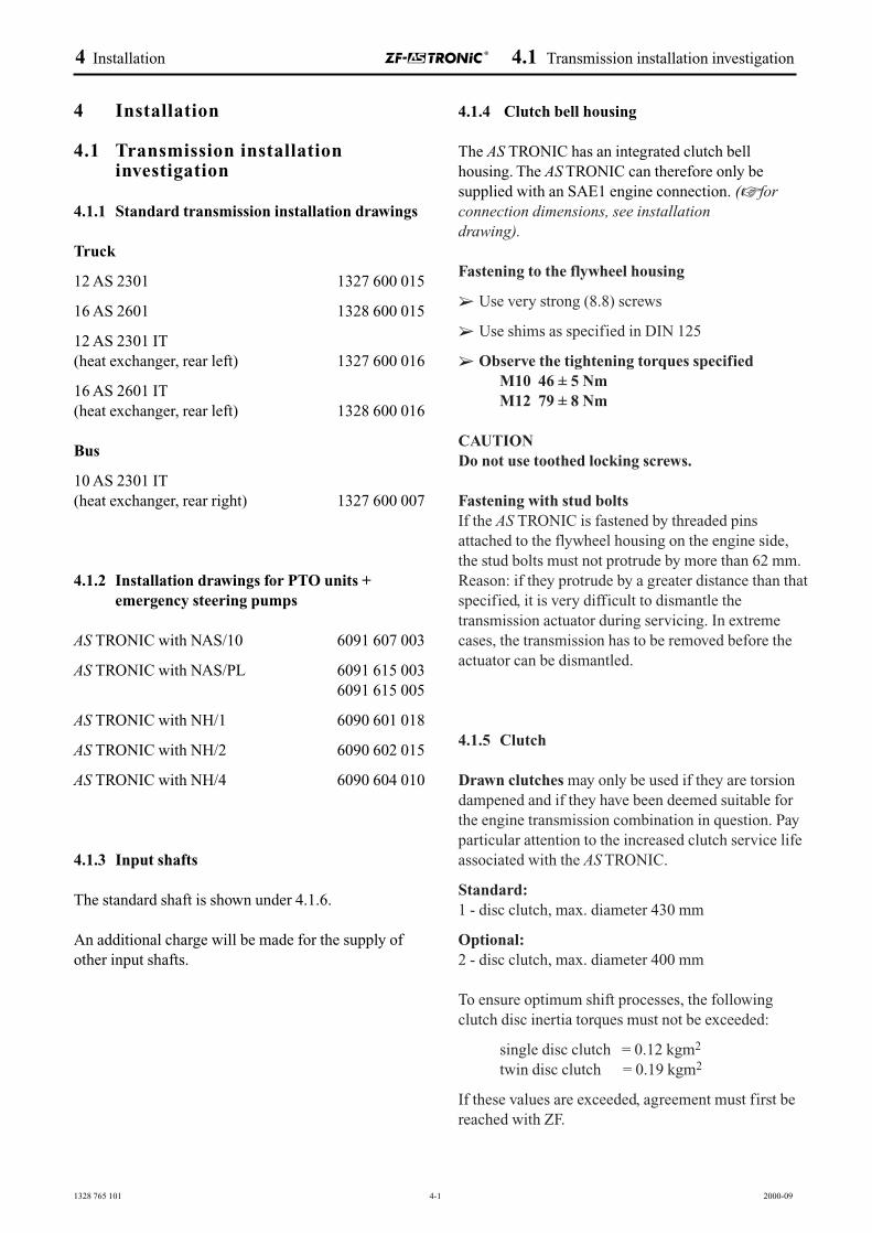
4.1.6 Clutch release device
ZF-AS TRONIC is supplied with a clutch releasebearing as standard. The clutch actuator therefore nolonger has to be fitted at the OEM on the assemblyline. The snap-on ring on the clutch release bearing isthe ZF-AS TRONIC interface with the clutch.
The OEM must provide ZF with the dimensions andtolerances shown in Fig. 1. These are queried in thecustomer specification.
014878
Ø 2
5 f7
102,3
109
70
Z
A
31,75
Ø 5
0,3
Fig. 1014 878
Engine connection length Disc flywheel housing
Set length for clutch
Length of push rodis designed by ZF
Max. travel ofclutch actuator
“Y” wear + tolerance
“X” release + tolerance
approx. 34 mm max. clutch releasebearing travel
4 Installation 4.1 Transmission installation investigation
1328 765 101 4-3 2000-09
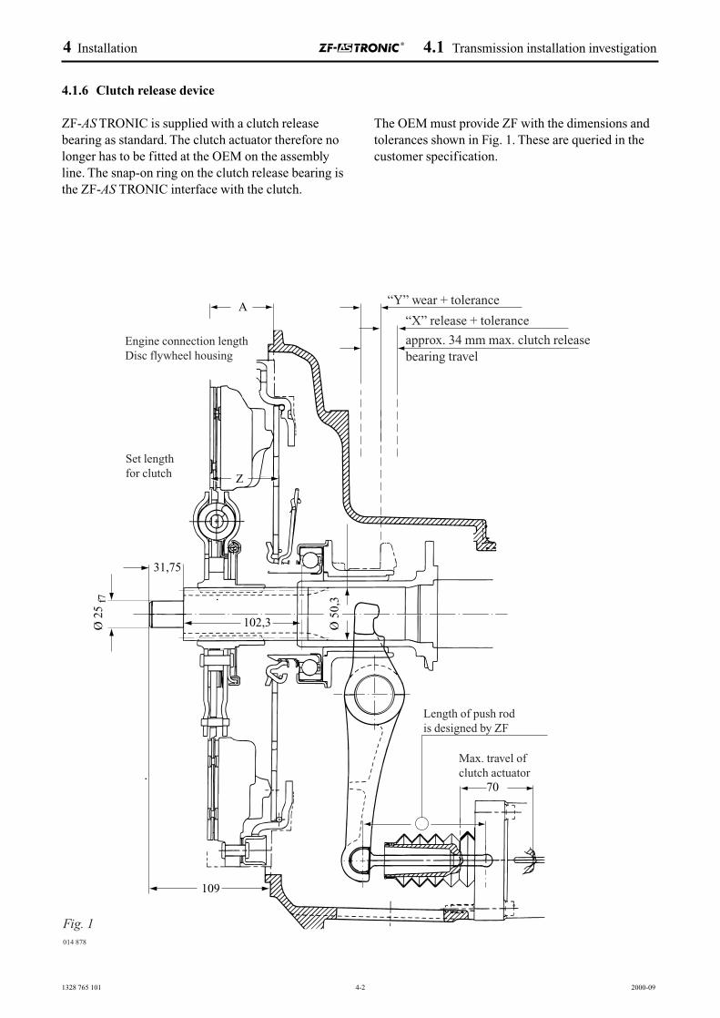
4.1.7 Engine connection
To ensure perfect function of the “engine/transmission” combination,
➢ the centre of the pilot bearing (usually the centreof the crankshaft) relative to the centre of thetransmission input
and
➢ the connection face on the engine
may only deviate from the geometrically idealposition if within certain limits.The following tolerances are permitted in relation tothe crankshaft axes:
➢ 0.1 mm roundness tolerance A for thecrankshaft bore (for the roller bearing whichguides the transmission input shaft)
➢ 0.2 mm roundness tolerance B for the centringbore (to support the transmission) in the flywheelhousing
➢ 0.1 mm planeness tolerance C for thetransmission connection surfaces on the flywheelhousing
For these tolerances, we also make reference to thedimensions and tolerances specified in ISO 7649.
Pilot bearing
A life-long lubricated ball bearing, sealed on bothsides is required for permanent input shaft guidance.The seal material must be resistant to temperatures ofbetween –40 and +150 °C. The roller bearing greasemust also be resistant to temperatures of between –40and +150 °C. The seal material must be resistant tocorrosion.
016 857
016 855
016 856
Magnetic stand
Flywheel
Dial gauge
Crank-shaft
Engine housing
A
Magnetic stand
Flywheel
Dial gauge
Crank-shaft
Engine housing B
Magnetic stand
Flywheel
Dial gauge
Crank-shaft
Engine housingC
4 Installation 4.1 Transmission installation investigation
1328 765 001 4-4 2000-09
E
A
C
BA
E
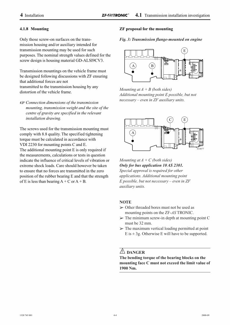
4.1.8 Mounting
Only those screw-on surfaces on the trans-mission housing and/or auxiliary intended fortransmission mounting may be used for suchpurposes. The nominal strength values defined for thescrew design is housing material GD-ALSI9CV3.
Transmission mountings on the vehicle frame mustbe designed following discussions with ZF ensuringthat additional forces are not transmitted to the transmission housing by anydistortion of the vehicle frame.
☞ Connection dimensions of the transmissionmounting, transmission weight and the site of thecentre of gravity are specified in the relevantinstallation drawing.
The screws used for the transmission mounting mustcomply with 8.8 quality. The specified tighteningtorque must be calculated in accordance with VDI 2230 for mounting points C and E.The additional mounting point E is only required ifthe measurements, calculations or tests in questionindicate the influence of critical levels of vibration orextreme shock loads. Care should however be takento ensure that no forces are transmitted in the zeroposition of the rubber bearing E and that the strengthof E is less than bearing A + C or A + B.
ZF proposal for the mounting
Fig. 3: Transmission flange-mounted on engine
Mounting at A + B (both sides)Additional mounting point E possible, but not necessary – even in ZF auxiliary units.
Mounting at A + C (both sides)Only for bus application 10 AS 2301.Special approval is required for other applications. Additional mounting point E possible, but not necessary – even in ZF auxiliary units.
NOTE➢ Other threaded bores must not be used as
mounting points on the ZF-AS TRONIC. ➢ The minimum screw-in depth at mounting point C
must be 32 mm.➢ The maximum vertical loading permitted at point
E is ± 3g. Otherwise E will have to be supported.
DANGERThe bending torque of the bearing blocks on themounting face C must not exceed the limit value of1900 Nm.
!
014877
4 Installation 4.1 Transmission installation investigation
1328 765 101 4-5 2000-09
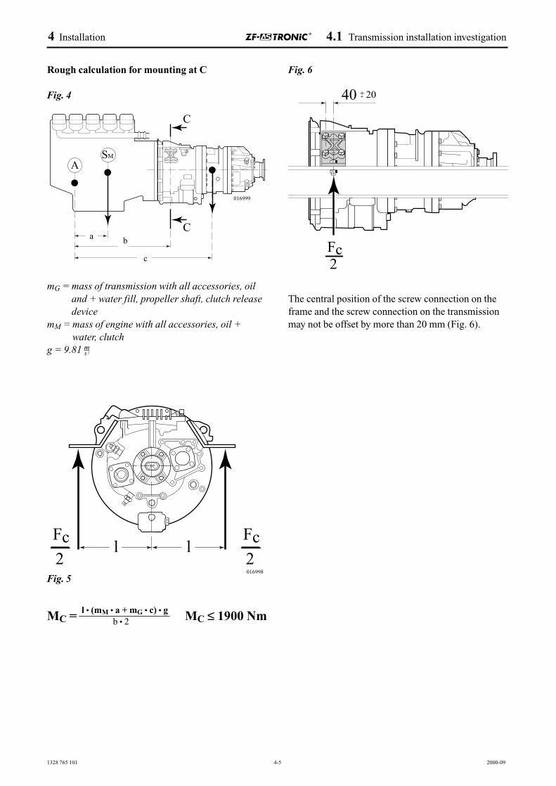
Rough calculation for mounting at C
Fig. 4
mG = mass of transmission with all accessories, oiland + water fill, propeller shaft, clutch releasedevice
mM = mass of engine with all accessories, oil +water, clutch
g = 9.81 m
Fig. 5
MC = MC ≤ 1900 Nm
Fig. 6
The central position of the screw connection on theframe and the screw connection on the transmissionmay not be offset by more than 20 mm (Fig. 6).
C
Ca b
c
ASM
s 2
Fc2
Fc2
l l016998
l • (mM • a + mG • c) • gb • 2
Fc2
40 20+-
016999
4 Installation 4.1 Transmission installation investigation
1328 765 101 4-6 2000-09
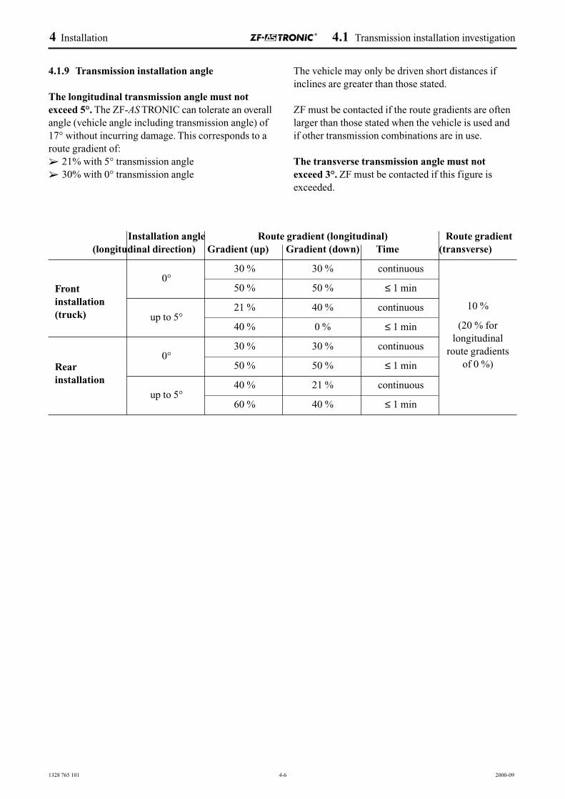
4.1.9 Transmission installation angle
The longitudinal transmission angle must notexceed 5°. The ZF-AS TRONIC can tolerate an overallangle (vehicle angle including transmission angle) of17° without incurring damage. This corresponds to aroute gradient of: ➢ 21% with 5° transmission angle➢ 30% with 0° transmission angle
The vehicle may only be driven short distances ifinclines are greater than those stated.
ZF must be contacted if the route gradients are oftenlarger than those stated when the vehicle is used andif other transmission combinations are in use.
The transverse transmission angle must notexceed 3°. ZF must be contacted if this figure isexceeded.
Installation angle Route gradient (longitudinal) Route gradient(longitudinal direction) Gradient (up) Gradient (down) Time (transverse)
0°30 % 30 % continuous
50 % 50 % ≤ 1 min
up to 5°21 % 40 % continuous
40 % 0 % ≤ 1 min
0°30 % 30 % continuous
50 % 50 % ≤ 1 min
up to 5°40 % 21 % continuous
60 % 40 % ≤ 1 min
Rearinstallation
10 %
(20 % for longitudinal
route gradientsof 0 %)
Frontinstallation(truck)
4 Installation 4.1 Transmission installation investigation
1328 765 101 4-7 1999-12
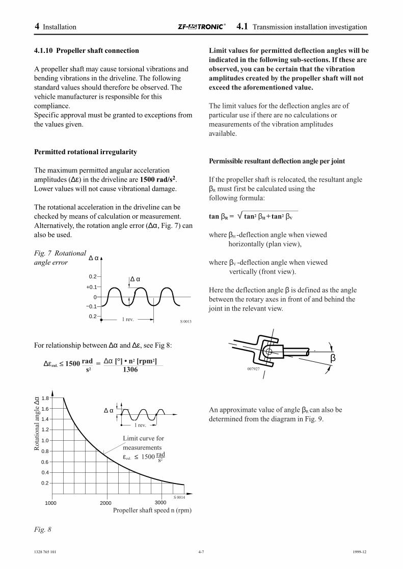
4.1.10 Propeller shaft connection
A propeller shaft may cause torsional vibrations andbending vibrations in the driveline. The followingstandard values should therefore be observed. Thevehicle manufacturer is responsible for thiscompliance.Specific approval must be granted to exceptions fromthe values given.
Permitted rotational irregularity
The maximum permitted angular acceleration amplitudes (∆ε) in the driveline are 1500 rad/s2.Lower values will not cause vibrational damage.
The rotational acceleration in the driveline can bechecked by means of calculation or measurement.Alternatively, the rotation angle error (∆α, Fig. 7) canalso be used.
Fig. 7 Rotational angle error
For relationship between ∆α and ∆ε, see Fig 8:
∆εzul. ≤ 1500 rad = ∆α [°] • n2 [rpm2]s2 1306
Fig. 8
0.2
+0.1
0
0.1
0.2
∆ α
∆ α
S 0013
Limit values for permitted deflection angles will beindicated in the following sub-sections. If these areobserved, you can be certain that the vibrationamplitudes created by the propeller shaft will notexceed the aforementioned value.
The limit values for the deflection angles are of particular use if there are no calculations or measurements of the vibration amplitudes available.
Permissible resultant deflection angle per joint
If the propeller shaft is relocated, the resultant angleβR must first be calculated using the following formula:
tan βR = √ tan2 βH +tan2 βV
where βH -deflection angle when viewed horizontally (plan view),
where βV -deflection angle when viewed vertically (front view).
Here the deflection angle β is defined as the anglebetween the rotary axes in front of and behind thejoint in the relevant view.
An approximate value of angle βR can also bedetermined from the diagram in Fig. 9.
1.2
1.8
1.6
1.4
1.0
0.8
0.6
0.4
0.2
1000 2000 3000
∆ α
Propeller shaft speed n (rpm)
Rot
atio
nal a
ngle
∆α
Limit curve formeasurements εzul. ≤ 1500 rad
s2
S 0014
β007927
1 rev.
1 rev.
4 Installation 4.1 Transmission installation investigation
1328 765 101 4-8 1999-12
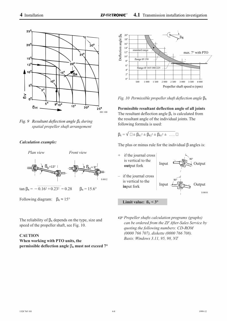
Fig. 9 Resultant deflection angle βR duringspatial propeller shaft arrangement
Calculation example:
Plan view Front view
tan βR = – 0.162 +0.232 = 0.28 βR = 15.6°
Following diagram: βR ≈ 15°
The reliability of βR depends on the type, size andspeed of the propeller shaft, see Fig. 10.
CAUTIONWhen working with PTO units, the permissible deflection angle βR must not exceed 7°
Fig. 10 Permissible propeller shaft deflection angle βR
Permissible resultant deflection angle of all jointsThe resultant deflection angle βE is calculated fromthe resultant angle of the individual joints. Thefollowing formula is used:
βE = √ ± βR12 ± βR2
2 ± βR32 ± . . .
The plus or minus rule for the individual β angles is:
+ if the journal crossis vertical to the
Input Outputoutput fork
– if the journal crossis vertical to the
Input Outputinput fork
Limit value: ßE < 3°
☞ Propeller shafts calculation programs (graphs)can be ordered from the ZF After-Sales Service byquoting the following numbers: CD-ROM (0000 766 707), diskette (0000 766 708). Basis: Windows 3.11, 95, 98, NT
500 1 000 1 500 2 000 2 500 3 000 3 500 4 000
18°
20°
16°
14°
12°
10°max. 7° bei Nebenabtrieb
8°
6°
4°
2°
0°
Beu
gew
inke
l βR
Standard-Baureihe
Gelenkwellendrehzahl n (1/min)
R
Flansch-Ø 165/180/225
Flansch-Ø 150
β
90°
90°
S 0010
001 100
=13°HV ß = 9°ß
S 0012
max. 7° with PTOstandard range
flange Ø 150
flange Ø 165/180/225
Propeller shaft speed n (rpm)
Def
lect
ion
angl
e β R
4 Installation 4.1 Transmission installation investigation
1328 765 101 4-9 1999-12
12°2ß =
12°1ß =
1ß 5°=
4°2ß =
15°1ß =
14°2ß =
12°1ß =
12°2ß =
1ß 5°=
4°2ß =
15°1ß =
14°2ß =
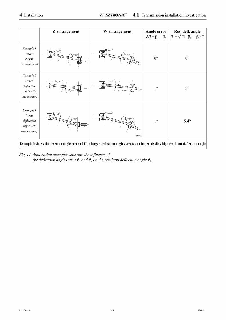
Z arrangement W arrangement Angle error Res. defl. angle∆β = β1 – β2 βE = √ – β1
2 + β22
0° 0°
1° 3°
1° 5,4°
Example 3 shows that even an angle error of 1° in larger deflection angles creates an impermissibly high resultant deflection angle
Example3
(large
deflection
angle with
angle error)S 0011
Fig. 11 Application examples showing the influence ofthe deflection angles sizes β1 and β2 on the resultant deflection angle βE
Example 1
(exact
Z or W
arrangement)
Example 2
(small
deflection
angle with
angle error)
4 Installation 4.1 Transmission installation investigation
1328 765 101 4-10 1999-12
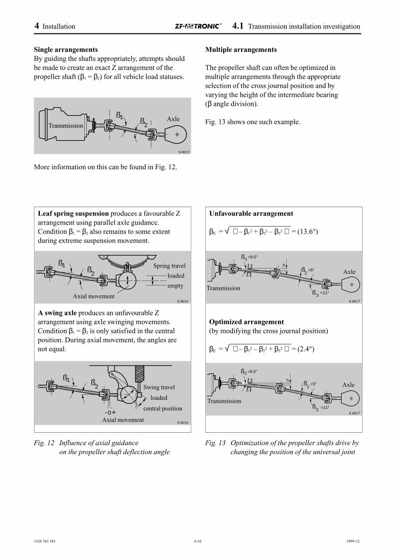
Single arrangementsBy guiding the shafts appropriately, attempts shouldbe made to create an exact Z arrangement of thepropeller shaft (β1 = β2) for all vehicle load statuses.
More information on this can be found in Fig. 12.
1ß2
ß
Leaf spring suspension produces a favourable Zarrangement using parallel axle guidance.Condition β1 = β2 also remains to some extent during extreme suspension movement.
A swing axle produces an unfavourable Zarrangement using axle swinging movements.Condition β1 = β2 is only satisfied in the centralposition. During axial movement, the angles arenot equal.
2ß
1ß
-0+
1ß2
ß
Unfavourable arrangement
βE = √ – β12 + β2
2 – β32 = (13.6°)
Optimized arrangement(by modifying the cross journal position)
βE = √ – β12 – β2
2 + β32 = (2.4°)
ß3
=5°
=9.5°
=11°
h
1ß
2ß
TransmissionAxle
S 0015
Spring travel
loaded
empty
Axial movement
Swing travel
loaded
central position
Axial movement
Transmission
Axle
S 0016
S 0016
S 0017
=11°ß3
=5°h
2ß
=9.5°1ß
Transmission
Axle
Multiple arrangements
The propeller shaft can often be optimized in multiple arrangements through the appropriateselection of the cross journal position and by varying the height of the intermediate bearing (β angle division).
Fig. 13 shows one such example.
Fig. 12 Influence of axial guidanceon the propeller shaft deflection angle
Fig. 13 Optimization of the propeller shafts drive bychanging the position of the universal joint
S 0017
4 Installation 4.1 Transmission installation investigation
1328 765 101 4-11 2000-09
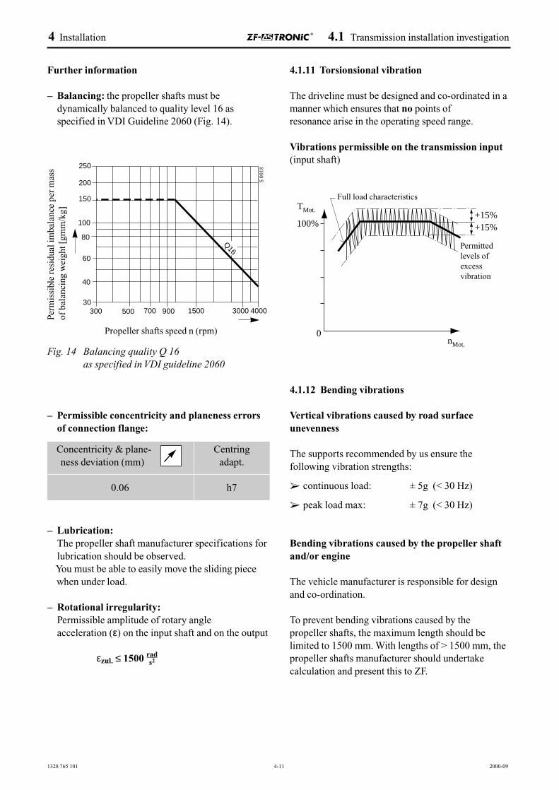
4.1.11 Torsionsional vibration
The driveline must be designed and co-ordinated in amanner which ensures that no points of resonance arise in the operating speed range.
Vibrations permissible on the transmission input(input shaft)
4.1.12 Bending vibrations
Vertical vibrations caused by road surfaceunevenness
The supports recommended by us ensure thefollowing vibration strengths:
➢ continuous load: ± 5g (< 30 Hz)
➢ peak load max: ± 7g (< 30 Hz)
Bending vibrations caused by the propeller shaftand/or engine
The vehicle manufacturer is responsible for designand co-ordination.
To prevent bending vibrations caused by the propeller shafts, the maximum length should belimited to 1500 mm. With lengths of > 1500 mm, thepropeller shafts manufacturer should undertakecalculation and present this to ZF.
Further information
– Balancing: the propeller shafts must bedynamically balanced to quality level 16 asspecified in VDI Guideline 2060 (Fig. 14).
Fig. 14 Balancing quality Q 16as specified in VDI guideline 2060
– Permissible concentricity and planeness errorsof connection flange:
– Lubrication:The propeller shaft manufacturer specifications forlubrication should be observed.You must be able to easily move the sliding piecewhen under load.
– Rotational irregularity:Permissible amplitude of rotary angle acceleration (ε) on the input shaft and on the output
εzul. ≤ 1500
Q16
300 500 700 900 1500 3000 400030
40
60
80
100
150
200
250
Perm
issi
ble
resi
dual
imba
lanc
e pe
r m
ass
of b
alan
cing
wei
ght [
gmm
/kg]
Propeller shafts speed n (rpm)
S 0
018
Concentricity & plane- ness deviation (mm)
0.06
Centringadapt.
h7
Vollastkurve
zulässigeSchwingungs-überhöhungen
TMot.
100%
0nMot.
+15%+15%
Permittedlevels ofexcessvibration
Full load characteristics
rads2
4 Installation 4.1 Transmission installation investigation
1328 765 101 4-12 2000-09
12
150
Bitte f�r Servicezwecke den Aus/Einbauraum des
Getriebestellers freihalten
Please in case of any serviceactivities, we need de/installationspace for the transmission actuator
50
*
*
*
150*
*
4.1.13 Cover / impact protection
When the vehicle is used in instances where there isthe risk of transmission damage caused e.g. by bulkcargo and increased levels of dirt as a result of snow,salt water, dust and water, the relevant cover platesshould be used.Furthermore, the vehicle and vehicle body manufacturers must ensure that all overhead plugconnections are protected from damage (e.g. impactprotection).
4.1.14 Additional brackets
Screw connections on the ZF-AS TRONIC must notbe released at a later date to attach additional brackets.
4.1.15 Fording ability
CAUTIONZF-AS TRONIC is not capable of fording in itsvolume production version.
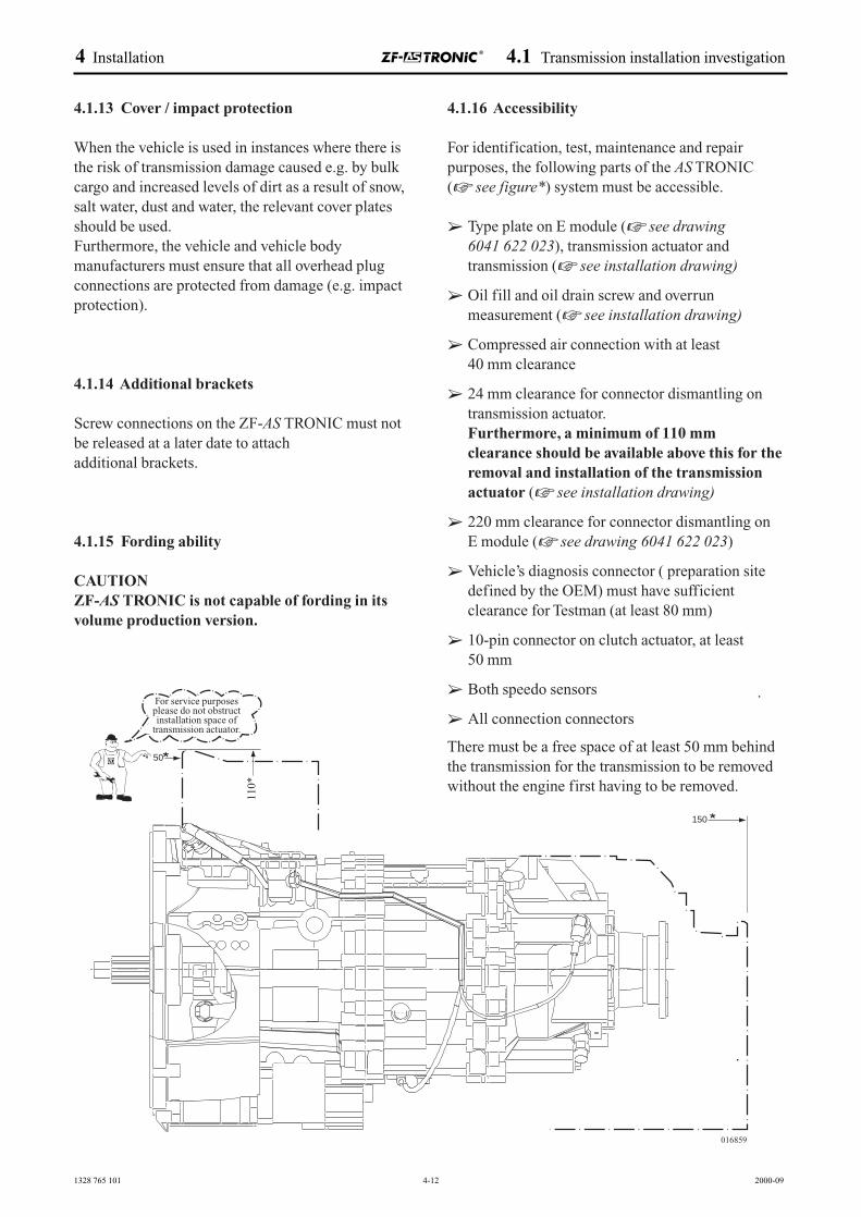
4.1.16 Accessibility
For identification, test, maintenance and repairpurposes, the following parts of the AS TRONIC (☞ see figure*) system must be accessible.
➢ Type plate on E module (☞ see drawing6041 622 023), transmission actuator andtransmission (☞ see installation drawing)
➢ Oil fill and oil drain screw and overrunmeasurement (☞ see installation drawing)
➢ Compressed air connection with at least 40 mm clearance
➢ 24 mm clearance for connector dismantling ontransmission actuator.Furthermore, a minimum of 110 mm clearance should be available above this for theremoval and installation of the transmissionactuator (☞ see installation drawing)
➢ 220 mm clearance for connector dismantling on E module (☞ see drawing 6041 622 023)
➢ Vehicle’s diagnosis connector ( preparation sitedefined by the OEM) must have sufficientclearance for Testman (at least 80 mm)
➢ 10-pin connector on clutch actuator, at least 50 mm
➢ Both speedo sensors
➢ All connection connectors
There must be a free space of at least 50 mm behindthe transmission for the transmission to be removedwithout the engine first having to be removed.
016859
110*
For service purposes please do not obstructinstallation space of
transmission actuator.
4 Installation 4.1 Transmission installation investigation
1328 765 101 4-13 2000-09
4.1.17 Additional guidelines for the vehicle body manufacturer
The reciprocal relationships of the vehicle’s electronic units must not be disturbed through theuse of a different wiring routing system (see systemstructure). In the event that fundamental changes are made to the installation and these effect the AS TRONIC system, the ZF installation approvalceases to apply.
4.1.18 Vehicle wiring(observe TKI 6029 705 003 vehicle wiring)
➢ Do not bend cables.
➢ Observe the temperature range (sees ambienttemperature Chapter).
➢ Do not fit to water, oil or pressure lines.
➢ Wiring must not be subjected to load.
➢ Avoid relative movements (chafing) between thewiring and its surroundings, e.g. vehicle frame.
➢ The cabling must be at a distance of at least 200 mm from the generator.
➢ Note any possible EMC interferences. Do notroute cables close to HF lines.
➢ Do not connect any earth/ground cables with thetransmission.
➢ When undertaking arc welding on the vehicleensure that currents do not flow through thetransmission and the associated electronic units.
➢ Limitations must not be placed on wiring whenundertaking any work on the vehicle.
Once work has been completed near the lines, theseshould be checked for damage. Also check that theconnectors are fitted correctly. The same applies tothe pneumatic lines, oil lines and water lines (e.g.with the Intarder).
The vehicle body manufacturers should payparticular attention to
☞ Chap. electrical system, TKI 6029 705 003 vehicle wiring, TKI 1328 761 005 transmissionactuator
☞ Chap. pneumatic system
CAUTIONNo consumers may be inserted downstream of thenon-return valve.
1328 765 101 4-14 2000-09
4.2 Temperatures
Temperature measuring journeys are required forapproval of all ZF-AS TRONIC applications.Emphasis should be placed on the followingmeasurements
➢ on uphill inclines
➢ on downhill inclines and
➢ once the vehicle has been parked
During these measuring journeys, the customer mustprove that
➢ the max. ambient temperature
➢ the temperature on the transmission actuator and
➢ the permissible permanent temperature
are below the limits specified here.
If this is not the case, measures will have to be takento reduce the temperature.
4.2.1 Permissible ambient temperatures on thetransmission
Max. ambient temperature: 95 °C (at 50 mm distance from transmission)
This temperature is measured in the area around thetransmission actuator cover.
4.2.2 Permissible oil temperatures
The permissible permanent temperature –measured in the transmission oil sump – in commercial vehicle applications is 110 °C. Briefpeaks in temperature (max. 30 min.) of up to 130 °C are permitted. The total of these peak valuesmay amount to a maximum of 10 % of the oil changeinterval.
• In bus applications, we recommend that temperature measuring journeys are undertakensince the installation conditions and the maximumspeed sometimes deviate considerably from thoseof other applications.
Here, e.g. with an outside temperature of 20 °C, ina journey lasting approx. 2 hours at maximumspeed, the transmission oil temperature should notexceed 90 °C.
• In special vehicles (cranes, fire engines etc.), wealso recommend that temperature measuringjourneys are undertaken. The same permissibletemperatures apply as for normal commercialvehicle applications.
• For transmissions with a ZF-Intarder and for the ZF-Transmatic (WSK), the permissibletemperatures specified in the relevant manualapply.
4.2.3 Causes of excess oil temperatures
The following could cause the the permissibletemperatures to be exceeded:
➢ encapsulated and noise-insulated transmissioninstallation
➢ insufficient distance between exhaust andtransmission
➢ exchange of air with transmission environmentnot possible (measures on vehicle)
➢ influence of heat from attached externallyproduced retarder
➢ very high or very low roadspeed
➢ oil level too high
➢ PTO unit operated with vehicle at standstill
The following measures are required:
➢ Distance between exhaust, water pipes, othersources and transmission: min. 100 mm
➢ Attach screen sheets to vehicle
4 Installation 4.2 Temperatures
1328 765 101 4-15 2000-09
4.2.4 Additional transmission cooling
If the permanent temperature in the oil sump is above110 °C, additional cooling is required. This applies inall instances in applications with
➢ heavy goods vehicles
➢ areas with outside temperatures of above 40 °C
Connecting a heat exchanger
The ZF-ASTRONIC has the connections required fora heat exchanger.
☞ See installation drawings in Chapter 4.1.1
Please note the following when connecting a heatexchanger:A by-pass line (by-pass valve 0.5 bar) must be fittedin front of the heat exchanger between the suctionand pressure side. The transmission must not beoperated if the heat exchanger is not connected.
☞ When undertaking oil filling and oil level monitoring in conjunction with a heat exchanger,the relevant operating manuals and installationdrawings should also be observed.
4.2.5 Use at very low temperatures
Outside temperature of down to – 30 °C
The ZF-AS TRONIC may only be used with oils inaccordance with relevant valid ZF list of lubricantsTE-ML 02. There are however certain restrictionswhich must be noted.
➢ ZF always recommends that a warming-up phaseof at least 10 minutes be observed at an increasedidling speed of approx. 1500 rpm whentemperatures are of below – 20 °C.
Outside temperatures down to – 40 °C
When using vehicles in outside temperaturespermanently between 0 °C and – 40 °C, there aresome restrictions which must be noted:
➢ ZF always recommends that a warming-up phaseof at least 10 minutes be observed at an increasedidling speed of approx. 1500 rpm when attemperatures of – 20 °C.
➢ At transmission temperatures of below – 35 °C,the transmission must be pre-heated before theengine is started. This can be done e.g. using hotair which must not however exceed + 150 °C onthe transmission.
CAUTIONDo not preheat on the transmission actuator.
– The engine may be started at transmissiontemperatures of between 0 and – 35 °C.
– The transmission can operate at trans-mission temperatures above – 30 °C and allfunctions are available. Longer shift timesshould be expected.
4.2.6 Storing the transmission at very low temperatures
The transmissions can be stored at outsidetemperatures of – 40 °C.
4 Installation 4.2 Temperatures
1328 765 101 4-16 2000-09
4.3 Oil f illing
The ZF-AS TRONIC transmission is supplied with oilas standard.
The oil change intervals are adapted to theappropriate oil grade of the oil filled into thetransmission (see TE-ML 02).
☞ For the approved oils and the oil change intervals attainable with them, please refer to thelatest relevant addition of the list of lubricantsTE-ML 02 (ZF no. 1205 754 022).
When attaching an Intarder and/or a PTO unit, the oilfilling quantity in the transmission rises.
☞ Reference is made to the oil quantities required inthe installation drawings, the Intarder technicalmanual (ZF no. 6085 765 004), standardoperating manuals and the PTO unit type sheet(ZF no. 1328 757 051).
The AS TRONIC transmission has one oil filler plugon each side and, depending on version (with/withoutIntarder), it has one or more oil drain plugs.
☞ For the position of these plugs and the tighteningtorques, please refer to the relevant installationdrawing (Chapter 4.1), the Intarder technicalmanual (ZF no. 6085 765 004) and the operatingmanuals (ZF no. 1327 758 001 and 1328 758 004).
Even if reference is made to oil quantities in theaforementioned documents, the oil level musthowever be correct on the transmission itself. Toensure that this is the case, with the vehicle standingon horizontal ground, fill oil into one of the oil fillingapertures until the filling height has reached thelower edge of the filling aperture and/or until oilstarts to escape from this oil filling aperture. ForIntarder applications, please note that completefilling is only reached once the vehicle is moved andafter the second filling process (☞ see Intardertechnical manual ZF no. 6085 754 004).
Information on transmission ventilation
The transmission is fitted with a vent on thetransmission actuator module as standard. The ventshould be protected from great amounts of water.Special applications such as off-road vehicles, refusecollection vehicles, milk-collecting vehicles whichare often cleaned with a water jet, dampness or dampair can be sucked through the vent through suddencooling of the transmission, resulting in theformation of condensate in the transmission. Evencoaches, in which the transmission is located in thewater ejector of the rear wheels, can be affected bythis. Since water in the transmission oil is harmful forthe transmission, ZF provides a hose ventilationsystem in the vehicle dry compartments. This isavailable as a retrofitting set rather than the standardvent and can be ordered from ZF After-Sales Serviceusing ZF number 1315 298 021.
4 Installation 4.3 Oil filling
1328 765 101 4-17 1999-12
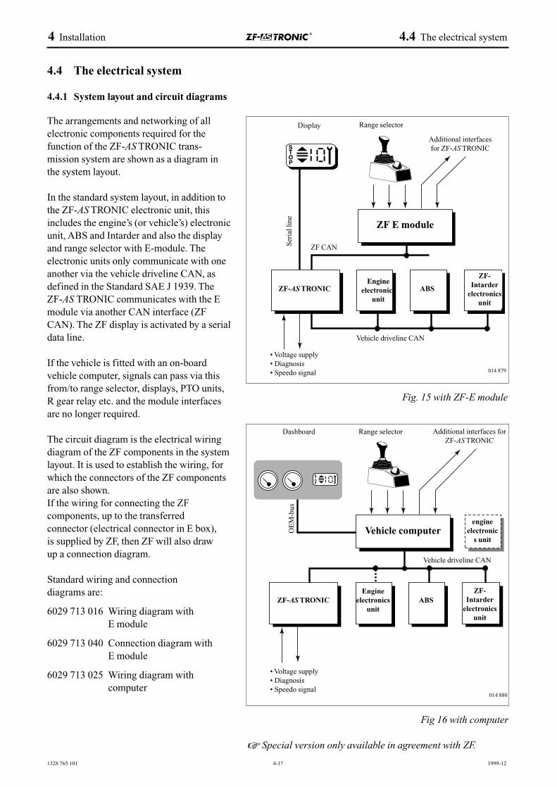
The arrangements and networking of allelectronic components required for thefunction of the ZF-AS TRONIC trans-mission system are shown as a diagram inthe system layout.
In the standard system layout, in addition tothe ZF-AS TRONIC electronic unit, thisincludes the engine’s (or vehicle’s) electronicunit, ABS and Intarder and also the displayand range selector with E-module. Theelectronic units only communicate with oneanother via the vehicle driveline CAN, asdefined in the Standard SAE J 1939. The ZF-AS TRONIC communicates with the Emodule via another CAN interface (ZFCAN). The ZF display is activated by a serialdata line.
If the vehicle is fitted with an on-boardvehicle computer, signals can pass via thisfrom/to range selector, displays, PTO units,R gear relay etc. and the module interfacesare no longer required.
The circuit diagram is the electrical wiringdiagram of the ZF components in the systemlayout. It is used to establish the wiring, forwhich the connectors of the ZF componentsare also shown.If the wiring for connecting the ZF components, up to the transferred connector (electrical connector in E box), is supplied by ZF, then ZF will also draw up a connection diagram.
Standard wiring and connection diagrams are:
6029 713 016 Wiring diagram with E module
6029 713 040 Connection diagram with E module
6029 713 025 Wiring diagram withcomputer
4 Installation 4.4 The electrical system
4.4 The electrical system
4.4.1 System layout and circuit diagrams
Display
ZF CAN
OE
M-b
usZF-AS TRONIC
ZF-AS TRONIC
• Voltage supply• Diagnosis• Speedo signal
• Voltage supply• Diagnosis• Speedo signal
Engineelectronics
unit
Engineelectronics
unit
engineelectronic
s unit
ABS
ABS
Vehicle computer
ZF-Intarder
electronicsunit
ZF-Intarder
electronicsunit
Ser
ial l
ine
ZF E module
Range selector
Vehicle driveline CAN
Vehicle driveline CAN
Dashboard
Additional interfacesfor ZF-AS TRONIC
Range selector Additional interfaces forZF-AS TRONIC
014 879
014 880
Fig. 15 with ZF-E module
Fig 16 with computer
☞ Special version only available in agreement with ZF.
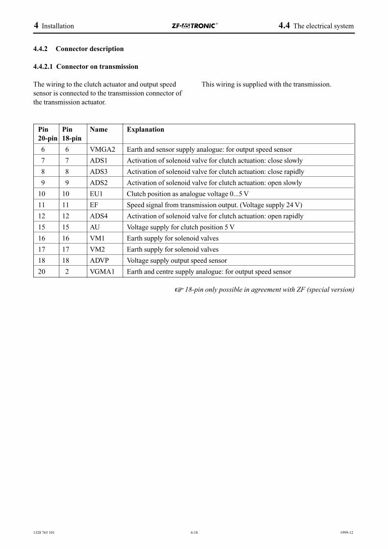
1328 765 101 4-18 1999-12
4 Installation 4.4 The electrical system
4.4.2 Connector description
4.4.2.1 Connector on transmission
The wiring to the clutch actuator and output speedsensor is connected to the transmission connector ofthe transmission actuator.
This wiring is supplied with the transmission.
Pin Pin Name Explanation20-pin 18-pin
6 6 VMGA2 Earth and sensor supply analogue: for output speed sensor
7 7 ADS1 Activation of solenoid valve for clutch actuation: close slowly
8 8 ADS3 Activation of solenoid valve for clutch actuation: close rapidly
9 9 ADS2 Activation of solenoid valve for clutch actuation: open slowly
10 10 EU1 Clutch position as analogue voltage 0...5 V
11 11 EF Speed signal from transmission output. (Voltage supply 24 V)
12 12 ADS4 Activation of solenoid valve for clutch actuation: open rapidly
15 15 AU Voltage supply for clutch position 5 V
16 16 VM1 Earth supply for solenoid valves
17 17 VM2 Earth supply for solenoid valves
18 18 ADVP Voltage supply output speed sensor
20 2 VGMA1 Earth and centre supply analogue: for output speed sensor
☞ 18-pin only possible in agreement with ZF (special version)
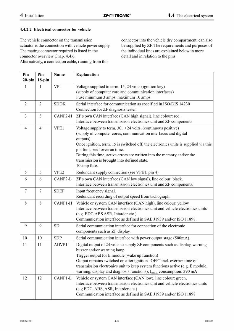
1328 765 101 4-19 2000-09
4.4.2.2 Electrical connector for vehicle
The vehicle connector on the transmission actuator is the connection with vehicle power supply.The mating connector required is listed in theconnector overview Chap. 4.4.6. Alternatively, a connection cable, running from this
connector into the vehicle dry compartment, can alsobe supplied by ZF. The requirements and purposes ofthe individual lines are explained below in moredetail and in relation to the pins.
4 Installation 4.4 The electrical system
Pin Pin Name Explanation20-pin 18-pin
1 1 VPI Voltage supplied to term. 15, 24 volts (ignition key)(supply of computer core and communication interfaces)Fuse minimum 3 amps, maximum 10 amps
2 2 SDDK Serial interface for communication as specified in ISO/DIS 14230 Connection for ZF diagnosis tester.
3 3 CANF2-H ZF’s own CAN interface (CAN high signal), line colour: red.Interface between transmission electronics unit and ZF components
4 4 VPE1 Voltage supply to term. 30, +24 volts, (continuous positive)(supply of computer cores, communication interfaces and digital outputs).Once ignition, term. 15 is switched off, the electronics units is supplied via thispin for a brief overrun time. During this time, active errors are written into the memory and/or thetransmission is brought into defined state. 10 amp fuse.
5 5 VPE2 Redundant supply connection (see VPE1, pin 4)
6 6 CANF2-L ZF’s own CAN interface (CAN low signal), line colour: black.Interface between transmission electronics unit and ZF components.
7 7 SDEF Input frequency signal.Redundant recording of output speed from tachograph.
8 8 CANF1-H Vehicle or system CAN interface (CAN high), line colour: yellow.Interface between transmission electronics unit and vehicle electronics units (e.g. EDC,ABS ASR, Intarder etc.).Communication interface as defined in SAE J1939 and/or ISO 11898.
9 9 SD Serial communication interface for connection of the electronic components such as ZF display.
10 10 SDP Serial communication interface with power output stage (500mA).
11 11 ADVP1 Digital output of 24 volts to supply ZF components such as display, warningbuzzer and/or warning lamp.Trigger output for E module (wake up function) Output remains switched on after ignition “OFF” incl. overrun time oftransmission electronics unit to keep system functions active (e.g. E module,warning, display and diagnosis functions); Imax. consumption: 390 mA
12 12 CANF1-L Vehicle or system CAN interface (CAN low), line colour: green, Interface between transmission electronics unit and vehicle electronics units(e.g EDC, ABS, ASR, Intarder etc.)Communication interface as defined in SAE J1939 and/or ISO 11898
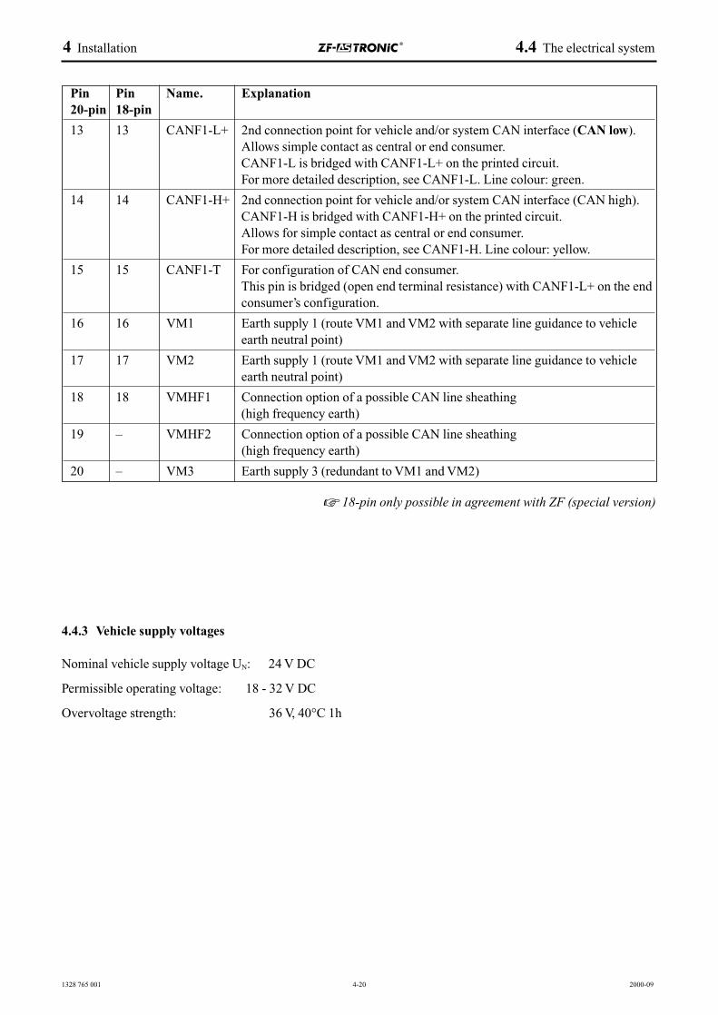
1328 765 001 4-20 2000-09
Pin Pin Name. Explanation20-pin 18-pin
13 13 CANF1-L+ 2nd connection point for vehicle and/or system CAN interface (CAN low).Allows simple contact as central or end consumer.CANF1-L is bridged with CANF1-L+ on the printed circuit.For more detailed description, see CANF1-L. Line colour: green.
14 14 CANF1-H+ 2nd connection point for vehicle and/or system CAN interface (CAN high).CANF1-H is bridged with CANF1-H+ on the printed circuit.Allows for simple contact as central or end consumer. For more detailed description, see CANF1-H. Line colour: yellow.
15 15 CANF1-T For configuration of CAN end consumer.This pin is bridged (open end terminal resistance) with CANF1-L+ on the endconsumer’s configuration.
16 16 VM1 Earth supply 1 (route VM1 and VM2 with separate line guidance to vehicleearth neutral point)
17 17 VM2 Earth supply 1 (route VM1 and VM2 with separate line guidance to vehicleearth neutral point)
18 18 VMHF1 Connection option of a possible CAN line sheathing(high frequency earth)
19 – VMHF2 Connection option of a possible CAN line sheathing(high frequency earth)
20 – VM3 Earth supply 3 (redundant to VM1 and VM2)
4 Installation 4.4 The electrical system
4.4.3 Vehicle supply voltages
Nominal vehicle supply voltage UN: 24 V DC
Permissible operating voltage: 18 - 32 V DC
Overvoltage strength: 36 V, 40°C 1h
☞ 18-pin only possible in agreement with ZF (special version)
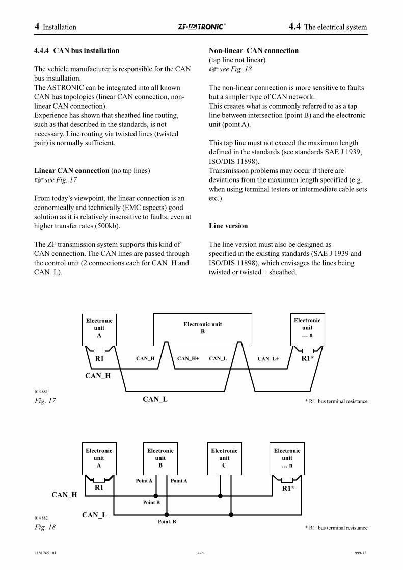
1328 765 101 4-21 1999-12
4.4.4 CAN bus installation
The vehicle manufacturer is responsible for the CANbus installation.The ASTRONIC can be integrated into all knownCAN bus topologies (linear CAN connection, non-linear CAN connection).Experience has shown that sheathed line routing,such as that described in the standards, is notnecessary. Line routing via twisted lines (twistedpair) is normally sufficient.
Linear CAN connection (no tap lines)☞ see Fig. 17
From today’s viewpoint, the linear connection is aneconomically and technically (EMC aspects) goodsolution as it is relatively insensitive to faults, even athigher transfer rates (500kb).
The ZF transmission system supports this kind ofCAN connection. The CAN lines are passed throughthe control unit (2 connections each for CAN_H andCAN_L).
Non-linear CAN connection(tap line not linear) ☞ see Fig. 18
The non-linear connection is more sensitive to faultsbut a simpler type of CAN network.This creates what is commonly referred to as a tapline between intersection (point B) and the electronicunit (point A).
This tap line must not exceed the maximum lengthdefined in the standards (see standards SAE J 1939,ISO/DIS 11898).Transmission problems may occur if there aredeviations from the maximum length specified (e.g.when using terminal testers or intermediate cable setsetc.).
Line version
The line version must also be designed as specified in the existing standards (SAE J 1939 andISO/DIS 11898), which envisages the lines beingtwisted or twisted + sheathed.
4 Installation 4.4 The electrical system
014882
* R1: bus terminal resistance
R1*
Fig. 17
* R1: bus terminal resistance
R1*
Fig. 18
Electronicunit
A
ElectronicunitA
Electronicunit
B
ElectronicunitC
Electronicunit… n
Electronic unitB
Electronicunit… n
014 881
014 882
R1
R1
CAN_H
CAN_H
CAN_L
CAN_L
CAN_H
Point A
Point B
Point. B
Point A
CAN_H+ CAN_L CAN_L+
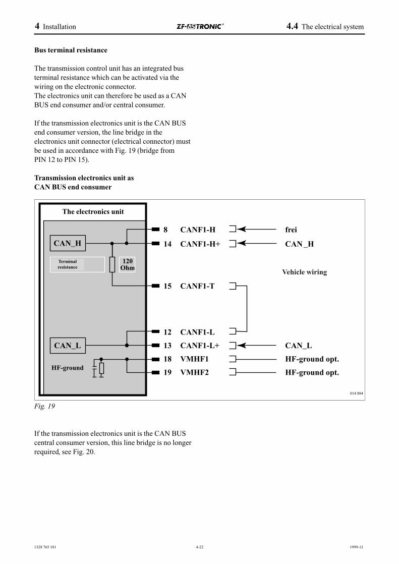
1328 765 101 4-22 1999-12
Bus terminal resistance
The transmission control unit has an integrated busterminal resistance which can be activated via thewiring on the electronic connector. The electronics unit can therefore be used as a CANBUS end consumer and/or central consumer.
If the transmission electronics unit is the CAN BUSend consumer version, the line bridge in theelectronics unit connector (electrical connector) mustbe used in accordance with Fig. 19 (bridge from PIN 12 to PIN 15).
Transmission electronics unit as CAN BUS end consumer
Fig. 19
If the transmission electronics unit is the CAN BUScentral consumer version, this line bridge is no longerrequired, see Fig. 20.
4 Installation 4.4 The electrical system
014 884
The electronics unit
Vehicle wiring
Terminalresistance
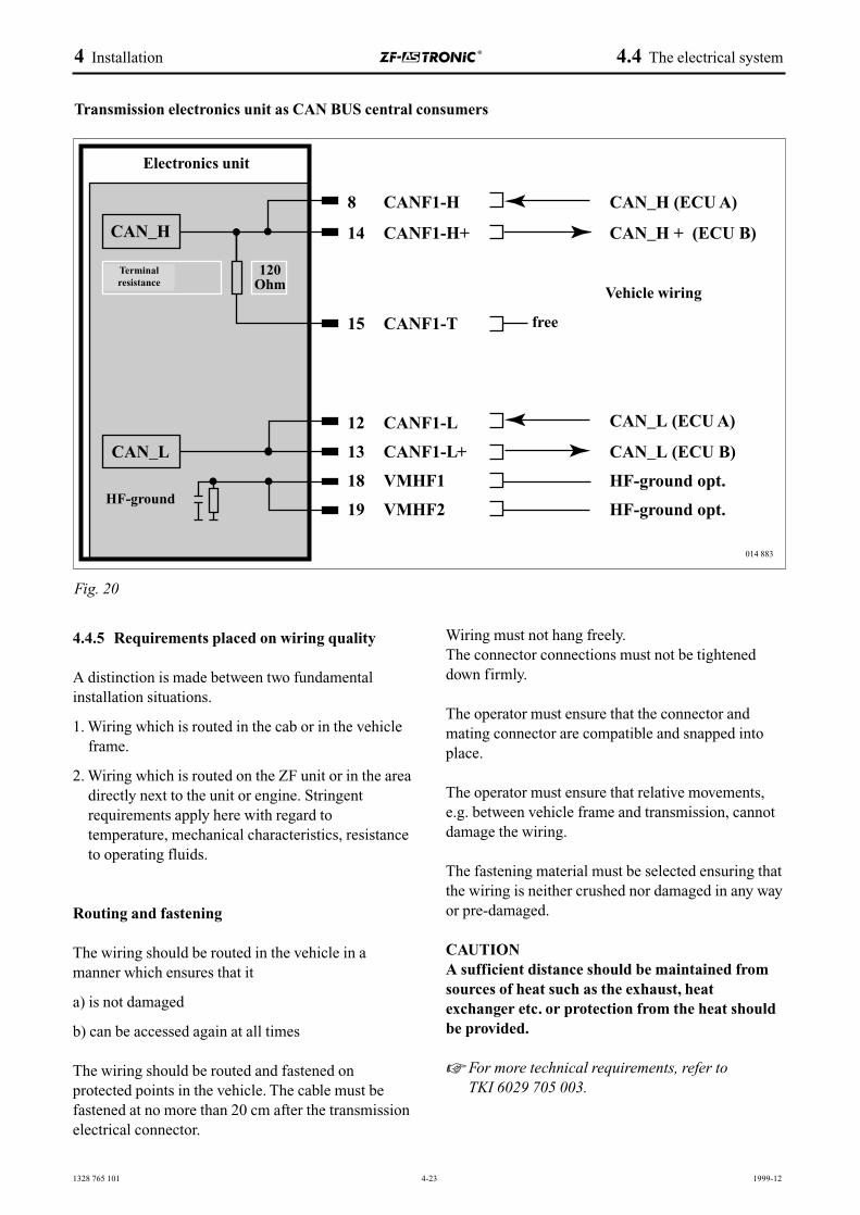
014 883
Fig. 20
Transmission electronics unit as CAN BUS central consumers
1328 765 101 4-23 1999-12
4.4.5 Requirements placed on wiring quality
A distinction is made between two fundamentalinstallation situations.
1. Wiring which is routed in the cab or in the vehicleframe.
2. Wiring which is routed on the ZF unit or in the areadirectly next to the unit or engine. Stringentrequirements apply here with regard totemperature, mechanical characteristics, resistanceto operating fluids.
Routing and fastening
The wiring should be routed in the vehicle in amanner which ensures that it
a) is not damaged
b) can be accessed again at all times
The wiring should be routed and fastened onprotected points in the vehicle. The cable must befastened at no more than 20 cm after the transmissionelectrical connector.
Wiring must not hang freely.The connector connections must not be tighteneddown firmly.
The operator must ensure that the connector andmating connector are compatible and snapped intoplace.
The operator must ensure that relative movements,e.g. between vehicle frame and transmission, cannotdamage the wiring.
The fastening material must be selected ensuring thatthe wiring is neither crushed nor damaged in any wayor pre-damaged.
CAUTIONA sufficient distance should be maintained fromsources of heat such as the exhaust, heatexchanger etc. or protection from the heat shouldbe provided.
☞ For more technical requirements, refer to TKI 6029 705 003.
4 Installation 4.4 The electrical system
Electronics unit
Vehicle wiring
free
Terminalresistance
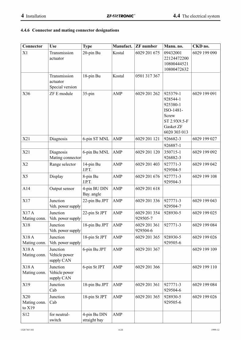
1328 765 101 4-24 1999-12
Connector Use Type Manufact. ZF number Manu. no. CKD no.
X1 Transmission 20-pin Bu Kostal 6029 201 675 09432001 6029 199 090actuator 22124472200
1080044452110800472632
Transmission 18-pin Bu Kostal 0501 317 367actuatorSpecial version
X36 ZF E module 35-pin AMP 6029 201 262 925379-1 6029 199 091928544-1925380-1ISO-1481-ScrewST 2.9X9.5-FGasket ZF6020 303 013
X21 Diagnosis 6-pin ST MNL AMP 6029 201 121 926682-3 6029 199 027
926887-1
X21 Diagnosis 6-pin Bu MNL AMP 6029 201 120 350715-1 6029 199 092Mating connector 926882-3
X2 Range selector 14-pin Bu AMP 6029 201 403 927771-3 6029 199 042J.P.T. 929504-5
X5 Display 8-pin Bu AMP 6029 201 676 927771-3 6029 199 108J.P.T. 929504-3
A14 Output sensor 4-pin BU DIN AMP 6029 201 618Bay. angle
X17 Junction 22-pin Bu JPT AMP 6029 201 336 927771-3 6029 199 043Veh. power supply 929504-7
X17 A Junction 22-pin St JPT AMP 6029 201 354 928930-5 6029 199 025Mating conn. Veh. power supply 929505-7
X18 Junction 18-pin Bu JPT AMP 6029 201 361 927771-3 6029 199 084Veh. power supply 929504-6
X18 A Junction 18-pin St JPT AMP 6029 201 365 928930-5 6029 199 026Mating conn. Veh. power supply 929505-6
X18 A Junction 6-pin Bu JPT AMP 6029 201 367 6029 199 109Mating conn. Vehicle power
supply CAN
X18 A Junction 6-pin St JPT AMP 6029 201 366 6029 199 110Mating conn. Vehicle power
supply CAN
X19 Junction 18-pin Bu JPT AMP 6029 201 361 927771-3 6029 199 084Cab 929504-6
X20 Junction 18-pin St JPT AMP 6029 201 365 928930-5 6029 199 026Mating conn. Cab 929505-6to X19
S12 for neutral- 4-pin Bu DIN AMPswitch straight bay
4 Installation 4.4 The electrical system
4.4.6 Connector and mating connector designations
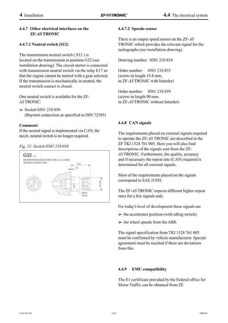
1328 765 101 4-25 2000-09
4.4.7 Other electrical interfaces on theZF-AS TRONIC
4.4.7.1 Neutral switch (S12)
The transmission neutral switch ( S12 ) is located on the transmission at position G32 (seeinstallation drawing). The circuit starter is connectedwith transmission neutral switch via the relay E17 sothat the engine cannot be started with a gear selected.If the transmission is mechanically in neutral, theneutral switch contact is closed.
One neutral switch is available for the ZF-AS TRONIC:
➢ Switch 0501 210 058(Bayonet connection as specified in DIN 72585)
Comment:If the neutral signal is implemented via CAN, themech. neutral switch is no longer required.
Fig. 21: Switch 0501 210 058
4.4.7.2 Speedo sensor
There is an output speed sensor on the ZF-ASTRONIC which provides the relevant signal for thetachographs (see installation drawing).
Drawing number: 0501 210 854
Order number: 0501 210 855 (screw-in length 19.8 mm, in ZF-AS TRONIC with Intarder)
Order number: 0501 210 859 (screw-in length 90 mm, in ZF-AS TRONIC without Intarder)
4.4.8 CAN signals
The requirements placed on external signals requiredto operate the ZF-AS TRONIC are described in theZF TKI 1328 761 005. Here you will also finddescriptions of the signals sent from the ZF-AS TRONIC. Furthermore, the quality, accuracy and if necessary the repeat rate (CAN) required isdetermined for all external signals.
Most of the requirements placed on the signalscorrespond to SAE J1939.
The ZF-AS TRONIC expects different higher repeatrates for a few signals only.
For today’s level of development these signals are
➢ the accelerator position (with idling switch)
➢ the wheel speeds from the ABS.
The signal specification from TKI 1328 761 005must be confirmed by vehicle manufacturer. Specialagreement must be reached if there are deviationsfrom this.
4.4.9 EMC compatibility
The E1 certificate provided by the Federal office forMotor Traffic can be obtained from ZF.
4 Installation 4.4 The electrical system
G32 1:1
2
1
BAJONETTANSCHLUSS DIN 72585-A1-2.1-A G/K1
BAJONET CONNECTION
SW27W.A.F.
Ø 2
3.6
35.1
1.5
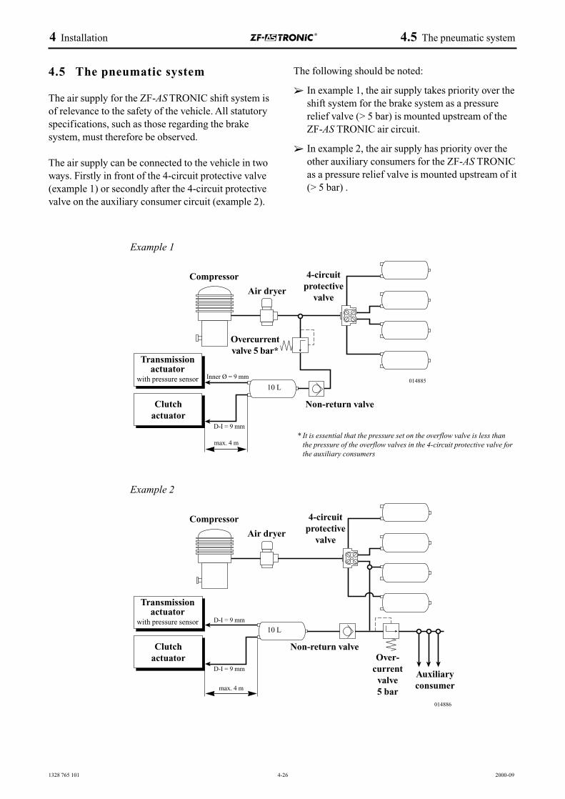
1328 765 101 4-26 2000-09
4 Installation 4.5 The pneumatic system
4.5 The pneumatic system
The air supply for the ZF-AS TRONIC shift system isof relevance to the safety of the vehicle. All statutoryspecifications, such as those regarding the brakesystem, must therefore be observed.
The air supply can be connected to the vehicle in twoways. Firstly in front of the 4-circuit protective valve(example 1) or secondly after the 4-circuit protectivevalve on the auxiliary consumer circuit (example 2).
The following should be noted:
➢ In example 1, the air supply takes priority over theshift system for the brake system as a pressurerelief valve (> 5 bar) is mounted upstream of theZF-AS TRONIC air circuit.
➢ In example 2, the air supply has priority over theother auxiliary consumers for the ZF-AS TRONICas a pressure relief valve is mounted upstream of it(> 5 bar) .
Example 1
Example 2
Transmissionactuator
with pressure sensor
Transmissionactuator
with pressure sensor
Clutchactuator
Compressor
Air dryer
Overcurrentvalve 5 bar*
4-circuitprotective
valve
Non-return valve
10 L
Inner Ø = 9 mm
D-I = 9 mm
max. 4 m
Clutchactuator
Compressor
Air dryer
Over-current
valve 5 bar
Auxiliaryconsumer
4-circuitprotective
valve
Non-return valve
10 LD-I = 9 mm
D-I = 9 mm
max. 4 m
014885
014886
* It is essential that the pressure set on the overflow valve is less thanthe pressure of the overflow valves in the 4-circuit protective valve forthe auxiliary consumers
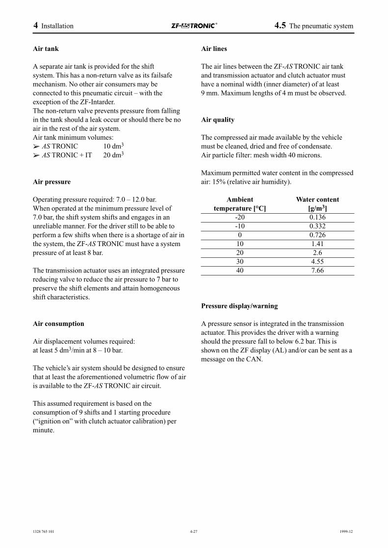
1328 765 101 4-27 1999-12
4 Installation 4.5 The pneumatic system
Air tank
A separate air tank is provided for the shift system. This has a non-return valve as its failsafemechanism. No other air consumers may beconnected to this pneumatic circuit – with theexception of the ZF-Intarder.The non-return valve prevents pressure from fallingin the tank should a leak occur or should there be noair in the rest of the air system. Air tank minimum volumes:➢ AS TRONIC 10 dm3
➢ AS TRONIC + IT 20 dm3
Air pressure
Operating pressure required: 7.0 – 12.0 bar.When operated at the minimum pressure level of 7.0 bar, the shift system shifts and engages in anunreliable manner. For the driver still to be able toperform a few shifts when there is a shortage of air inthe system, the ZF-AS TRONIC must have a systempressure of at least 8 bar.
The transmission actuator uses an integrated pressurereducing valve to reduce the air pressure to 7 bar topreserve the shift elements and attain homogeneousshift characteristics.
Air consumption
Air displacement volumes required:at least 5 dm3/min at 8 – 10 bar.
The vehicle’s air system should be designed to ensurethat at least the aforementioned volumetric flow of airis available to the ZF-AS TRONIC air circuit.
This assumed requirement is based on the consumption of 9 shifts and 1 starting procedure(“ignition on” with clutch actuator calibration) perminute.
Air lines
The air lines between the ZF-AS TRONIC air tankand transmission actuator and clutch actuator musthave a nominal width (inner diameter) of at least 9 mm. Maximum lengths of 4 m must be observed.
Air quality
The compressed air made available by the vehiclemust be cleaned, dried and free of condensate. Air particle filter: mesh width 40 microns.
Maximum permitted water content in the compressedair: 15% (relative air humidity).
Ambient Water contenttemperature [°C] [g/m3]
-20 0.136-10 0.3320 0.72610 1.4120 2.630 4.5540 7.66
Pressure display/warning
A pressure sensor is integrated in the transmissionactuator. This provides the driver with a warningshould the pressure fall to below 6.2 bar. This isshown on the ZF display (AL) and/or can be sent as amessage on the CAN.
1328 765 101 4-28 2000-09
4 Installation 4.6 Auxiliary units
4.6 Auxiliary units
4.6.1 ZF-Intarder
The ZF-Intarder cannot be attached at a later date.The ZF-Intarder must always be taken intoconsideration at the time when the transmission orderis placed.
During ZF-Intarder applications, particular attentionshould be paid to the peripheral components such asattachment of the electronic units, wiring and coolerconnection. The number of impulses issued by thespeedo sensor differs slightly to that issued whenused without the Intarder.
☞ For installation instructions and interfacedescriptions, please refer to the ZF-Intardertechnical manual (ZF no. 6085 765 004).
The ZF-Intarder electronics unit software takes intoconsideration the necessary signal exchange with theZF-AS TRONIC, performed by the CAN bus.
☞ For special features associated with oil filling ofthe ZF-AS TRONIC and Intarder combination,please refer to the ZF-Intarder technical manual(ZF no. 6085 765 004).
The initial installation of a ZF-AS TRONIC and ZF-Intarder system combination must be commissionedand approved by ZF.
4.6.2 Externally produced retarders
Whenever attaching externally produced retarders,always consult the technical sales team from ZF. The requirements governing mechanical, pneumatic,electrical interfaces and signal exchange with the ZF-AS TRONIC must be adapted accordingly. Here,it may be necessary to separately consider the systemsafety of the entire unit and to have the vehiclemanufacturer undertake an overall vehicle systemFMEA.
If ZF does not expressly issue approval for anexternally produced retarder, ZF takes no liability orresponsibility for these unit combinations or for thefunctional and operational safety of the entire system.
4.6.3 ZF PTO units
ZF PTO units can be attached in three ways. Firstly inthe plant when the transmission is supplied, secondlyat a later date by the vehicle manufacturer or lastly inthe end customer’s finished vehicle.
☞ The attachment manual for ZF PTO units, ZF no. 1328 757 051, provides information on the selection of ZF PTO units and on the attachment specifications.
This manual pays particular attention to the fact thatwhen a PTO unit is mechanically attached, theelectronics unit in the ZF-AS TRONIC will alsorequire additional programming to ensure theoperational safety of the system used in conjunctionwith the automated clutch. If the vehiclemanufacturer is to attach the PTO units, the data setrequired should be clarified with the technical salesteam. If supplied vehicles are to be retrofitted, thistask is undertaken by the ZF service centres. If thePTO unit is attached and the ZF attachmentspecifications (e.g. program changes to theelectronics unit) are not taken into consideration, thenZF takes no responsibility for this unit combinationor the functional and operational safety of the entiresystem.
The peripheral parts (wiring harness etc.) required forthe ZF PTO units must be provided by the vehiclemanufacturer. When retrofitting a vehicle which hasalready been supplied, the ZF service centres areavailable to offer their assistance.
4.6.4 PTO units produced by external companies
When attaching PTO units produced by externalcompanies, the assistance of the ZF technical salesteam should always be obtained. The requirementsgoverning mechanical, pneumatic and electricalinterfaces to the ZF-AS TRONIC must be adaptedaccordingly. Here, it may be necessary to separatelyconsider the system safety of the entire unit and tohave the vehicle manufacturer undertake an overallvehicle system FMEA to ensure operational safety ofthe system used in conjunction with the automatedclutch.
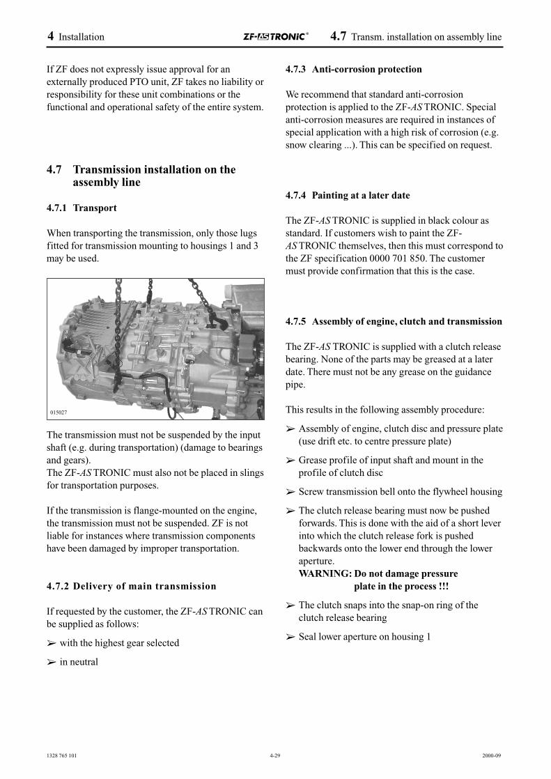
1328 765 101 4-29 2000-09
4 Installation 4.7 Transm. installation on assembly line
If ZF does not expressly issue approval for anexternally produced PTO unit, ZF takes no liability orresponsibility for these unit combinations or thefunctional and operational safety of the entire system.
4.7 Transmission installation on theassembly line
4.7.1 Transport
When transporting the transmission, only those lugsfitted for transmission mounting to housings 1 and 3may be used.
The transmission must not be suspended by the inputshaft (e.g. during transportation) (damage to bearingsand gears).The ZF-AS TRONIC must also not be placed in slingsfor transportation purposes.
If the transmission is flange-mounted on the engine,the transmission must not be suspended. ZF is notliable for instances where transmission componentshave been damaged by improper transportation.
4.7.2 Delivery of main transmission
If requested by the customer, the ZF-AS TRONIC canbe supplied as follows:
➢ with the highest gear selected
➢ in neutral
4.7.3 Anti-corrosion protection
We recommend that standard anti-corrosionprotection is applied to the ZF-AS TRONIC. Specialanti-corrosion measures are required in instances ofspecial application with a high risk of corrosion (e.g.snow clearing ...). This can be specified on request.
4.7.4 Painting at a later date
The ZF-AS TRONIC is supplied in black colour asstandard. If customers wish to paint the ZF-AS TRONIC themselves, then this must correspond tothe ZF specification 0000 701 850. The customermust provide confirmation that this is the case.
4.7.5 Assembly of engine, clutch and transmission
The ZF-AS TRONIC is supplied with a clutch releasebearing. None of the parts may be greased at a laterdate. There must not be any grease on the guidancepipe.
This results in the following assembly procedure:
➢ Assembly of engine, clutch disc and pressure plate(use drift etc. to centre pressure plate)
➢ Grease profile of input shaft and mount in theprofile of clutch disc
➢ Screw transmission bell onto the flywheel housing
➢ The clutch release bearing must now be pushedforwards. This is done with the aid of a short leverinto which the clutch release fork is pushedbackwards onto the lower end through the loweraperture.WARNING: Do not damage pressure
plate in the process !!!
➢ The clutch snaps into the snap-on ring of theclutch release bearing
➢ Seal lower aperture on housing 1
015027
1328 765 101 4-30 2000-09
4 Installation 4.7 Transm. installation on assembly line
4.7.6 EOL programming
To reduce delivery and service variants of the ZF-AS TRONIC, the ZF-AS TRONIC software can beprogrammed by the vehicle manufacturer.
For the EOL (end of line) programming of ZF-AS TRONIC-specific vehicle variants outside the ZForganization, agreement must be reached between thevehicle manufacturer and ZF on the program variantsneeded and the requirements placed on documentation,production and service processes.
The vehicle manufacturer adapts the EOLprogramming to the appropriate vehicleconfiguration using a vehicle parameter settingprocess (e.g. ratio of the rear axle, tyre radius, PTOconfigurations, ...).
The ZF-AS TRONIC is programmed using serial datatransfer.
The following description summarizes therequirements placed on ZF documentation and/or ZFservice.
☞ For the detailed requirements, please refer to ZF TKI 6009 774 005.
Documentation of the EOL programming
The delivery status of the ZF-AS TRONIC isdocumented at ZF by the order number of the vehiclemanufacturer.
Furthermore, ZF must also be able to fully understandall the EOL programming / parameter settingprocesses and modifications made outside the ZForganization, which extend over the service life of acontrol unit. A database is used for the ZFdocumentation. The data transfer between “vehiclemanufacturer - ZF” should be specified by suitableprocesses.
The OEM should be informed of the ZF-AS TRONIC-specific data for which ZF requires documentationand agreement should be reached on this.
ZF external programming equipment
ZF-AS TRONIC-specific data which is availableduring the EOL programming must be automatically forwarded to ZF. A standardizedprocess should be specified for this.
4.7.7 Delivery monitoring
A form is available for delivery monitoring and mustbe completed when the vehicle is commissioned andsent to ZF Friedrichshafen AG.
1328 765 101 4-31 2000-09
4 Installation 4.8 Additional information
4.8 Additional information
4.8.1 Operating and maintenance instructions
☞ The operating and maintenance instructionswhich can be found in the ZF-AS TRONICoperating manual should be observed (1328 758 004 trucks, 1327 758 001 for buses).This applies in particular to the oil filling and oillevel monitoring process. The ZF list of lubricantsshould also be observed (see Chapter. 4.4.3).
4.8.2 Handing over vehicle to the end customer
When the vehicle is handed over to the end customer, attention should be drawn to the function, operation and maintenance of the ZF-AS TRONIC units and the customer should also beprovided the copy of the ZF-AS TRONIC operatingmanual.
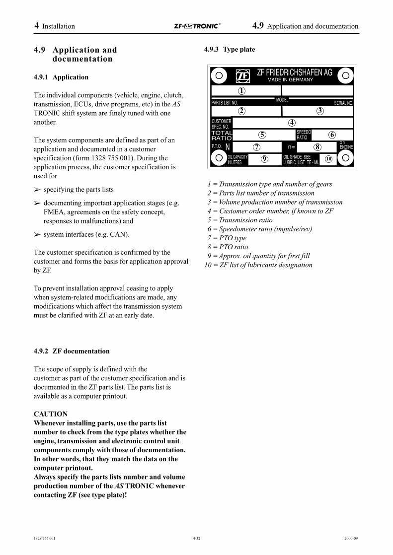
1328 765 001 4-32 2000-09
4 Installation 4.9 Application and documentation
4.9 Application and documentation
4.9.1 Application
The individual components (vehicle, engine, clutch,transmission, ECUs, drive programs, etc) in the ASTRONIC shift system are finely tuned with oneanother.
The system components are defined as part of anapplication and documented in a customerspecification (form 1328 755 001). During theapplication process, the customer specification isused for
➢ specifying the parts lists
➢ documenting important application stages (e.g.FMEA, agreements on the safety concept,responses to malfunctions) and
➢ system interfaces (e.g. CAN).
The customer specification is confirmed by thecustomer and forms the basis for application approvalby ZF.
To prevent installation approval ceasing to applywhen system-related modifications are made, anymodifications which affect the transmission systemmust be clarified with ZF at an early date.
4.9.2 ZF documentation
The scope of supply is defined with the customer as part of the customer specification and isdocumented in the ZF parts list. The parts list isavailable as a computer printout.
CAUTIONWhenever installing parts, use the parts listnumber to check from the type plates whether theengine, transmission and electronic control unitcomponents comply with those of documentation.In other words, that they match the data on thecomputer printout.Always specify the parts lists number and volumeproduction number of the AS TRONIC whenevercontacting ZF (see type plate)!
4.9.3 Type plate
1 = Transmission type and number of gears2 = Parts list number of transmission 3 = Volume production number of transmission4 = Customer order number, if known to ZF5 = Transmission ratio6 = Speedometer ratio (impulse/rev)7 = PTO type 8 = PTO ratio9 = Approx. oil quantity for first fill
10 = ZF list of lubricants designation
1
2
4
5
7
9 10
8
6
3
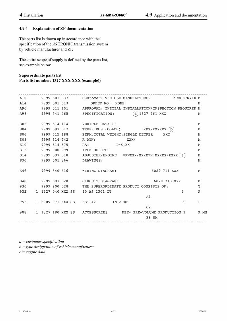
1328 765 101 4-33 2000-09
4 Installation 4.9 Application and documentation
4.9.4 Explanation of ZF documentation
The parts list is drawn up in accordance with thespecification of the AS TRONIC transmission systemby vehicle manufacturer and ZF.
The entire scope of supply is defined by the parts list,see example below.
Superordinate parts listParts list number: 1327 XXX XXX (example))
a = customer specificationb = type designation of vehicle manufacturerc = engine data
A10 9999 501 537 Customer: VEHICLE MANUFACTURER *COUNTRY:D MA14 9999 501 613 ORDER NO.: NONE MA90 9999 511 101 APPROVAL: INITIAL INSTALLATION*INSPECTION REQUIRED MA98 9999 541 465 SPECIFICATION: 1327 761 XXX M
S02 9999 514 114 VEHICLE DATA 1: MS04 9999 597 517 TYPE: BUS (COACH) XXXXXXXXXX MS06 9999 515 188 PERM.TOTAL WEIGHT:SINGLE DECKER XXT MS08 9999 514 742 R DYN: XXX* MS10 9999 514 575 RA: I=X,XX MS12 9999 000 999 ITEM DELETED MS14 9999 597 518 ADJUSTER/ENGINE *KWXXX/XXXX*N.MXXXX/XXXX MS30 9999 501 366 DRAWINGS: M
S46 9999 540 616 WIRING DIAGRAM: 6029 711 XXX M
S48 9999 597 520 CIRCUIT DIAGRAM: 6029 713 XXX M930 9999 200 028 THE SUPERORDINATE PRODUCT CONSISTS OF: T932 1 1327 040 XXX SS 10 AS 2301 IT 3 P
A1952 1 6009 071 XXX SS EST 42 INTARDER 3 P
C2988 1 1327 180 XXX SS ACCESSORIES NBE* PRE-VOLUME PRODUCTION 3 P MN
E8 MM
a
b
c

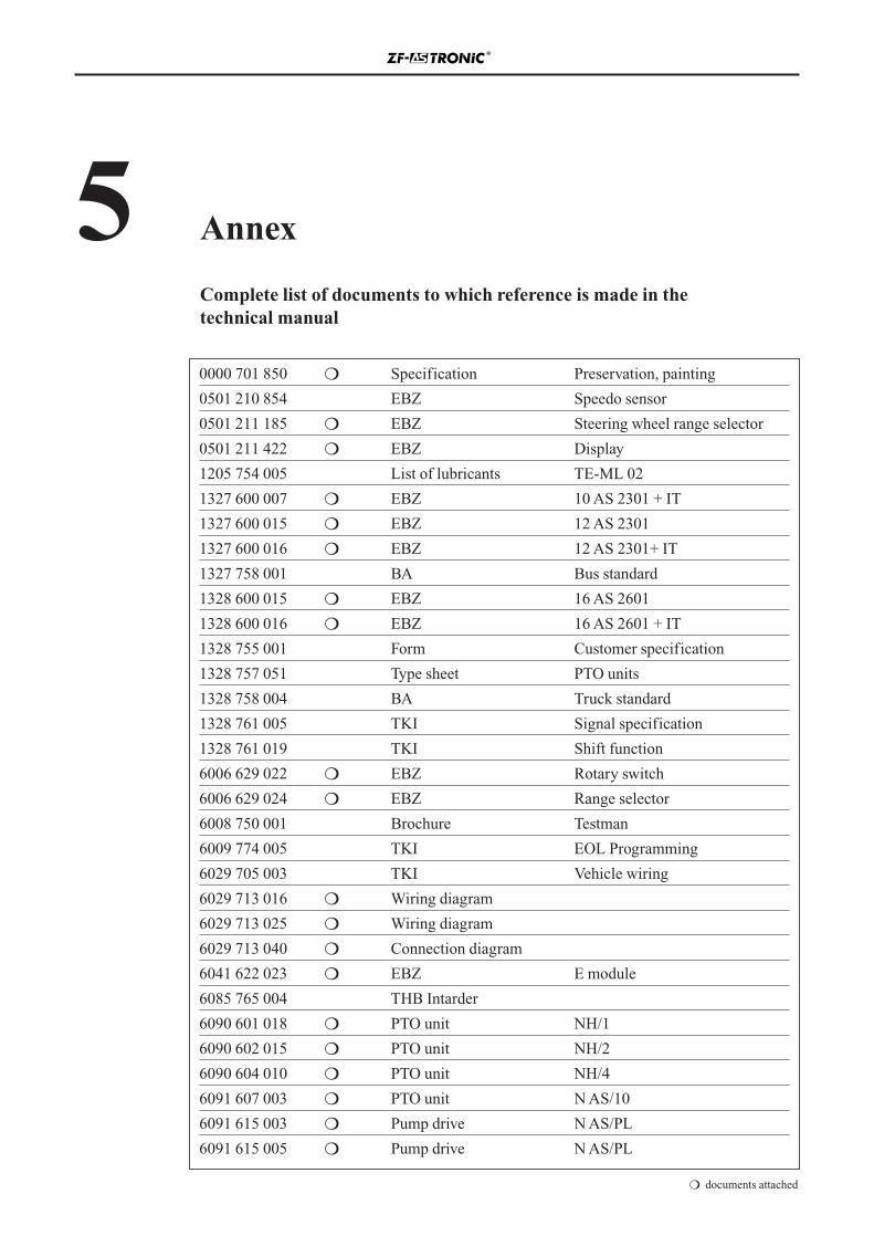
5 Annex
Complete list of documents to which reference is made in the technical manual
0000 701 850 ❍ Specification Preservation, painting
0501 210 854 EBZ Speedo sensor
0501 211 185 ❍ EBZ Steering wheel range selector
0501 211 422 ❍ EBZ Display
1205 754 005 List of lubricants TE-ML 02
1327 600 007 ❍ EBZ 10 AS 2301 + IT
1327 600 015 ❍ EBZ 12 AS 2301
1327 600 016 ❍ EBZ 12 AS 2301+ IT
1327 758 001 BA Bus standard
1328 600 015 ❍ EBZ 16 AS 2601
1328 600 016 ❍ EBZ 16 AS 2601 + IT
1328 755 001 Form Customer specification
1328 757 051 Type sheet PTO units
1328 758 004 BA Truck standard
1328 761 005 TKI Signal specification
1328 761 019 TKI Shift function
6006 629 022 ❍ EBZ Rotary switch
6006 629 024 ❍ EBZ Range selector
6008 750 001 Brochure Testman
6009 774 005 TKI EOL Programming
6029 705 003 TKI Vehicle wiring
6029 713 016 ❍ Wiring diagram
6029 713 025 ❍ Wiring diagram
6029 713 040 ❍ Connection diagram
6041 622 023 ❍ EBZ E module
6085 765 004 THB Intarder
6090 601 018 ❍ PTO unit NH/1
6090 602 015 ❍ PTO unit NH/2
6090 604 010 ❍ PTO unit NH/4
6091 607 003 ❍ PTO unit N AS/10
6091 615 003 ❍ Pump drive N AS/PL
6091 615 005 ❍ Pump drive N AS/PL
❍ documents attached
